toyota 1kd/2kd engine common rail system … 1kd 2kd...operation section 1±4 crankshaft position...
TRANSCRIPT
COMMON RAIL SYSTEM (CRS)TOYOTA 1KD/2KD ENGINE
Issued : September 2009
00400706E

© 2009 DENSO CORPORATION
All rights reserved. This material may not be reproduced or copied, in whole or in part, without the written permission of DENSO Corporation.
Table of Contents
Table of Contents
Operation Section
1. PRODUCT APPLICATION INFORMATION1.1 OUTLINE. . . . . . . . . . . . . . . . . . . . . . . . . . . . . . . . . . . . . . . . . . . . . . . . . . . . . . . . . . . . . . . . . . . . . . . . . . . . . . 1-1
1.2 Applicable Vehicles . . . . . . . . . . . . . . . . . . . . . . . . . . . . . . . . . . . . . . . . . . . . . . . . . . . . . . . . . . . . . . . . . . . . . . 1-1
1.3 Applicable Product List . . . . . . . . . . . . . . . . . . . . . . . . . . . . . . . . . . . . . . . . . . . . . . . . . . . . . . . . . . . . . . . . . . . 1-1
1.4 System Outline . . . . . . . . . . . . . . . . . . . . . . . . . . . . . . . . . . . . . . . . . . . . . . . . . . . . . . . . . . . . . . . . . . . . . . . . . 1-5
2. SUPPLY PUMP2.1 Change Item . . . . . . . . . . . . . . . . . . . . . . . . . . . . . . . . . . . . . . . . . . . . . . . . . . . . . . . . . . . . . . . . . . . . . . . . . . . 1-6
2.2 Suction Control Valve (SCV) . . . . . . . . . . . . . . . . . . . . . . . . . . . . . . . . . . . . . . . . . . . . . . . . . . . . . . . . . . . . . . . 1-6
3. RAIL3.1 Change Item . . . . . . . . . . . . . . . . . . . . . . . . . . . . . . . . . . . . . . . . . . . . . . . . . . . . . . . . . . . . . . . . . . . . . . . . . . . 1-8
4. INJECTOR4.1 Change Items . . . . . . . . . . . . . . . . . . . . . . . . . . . . . . . . . . . . . . . . . . . . . . . . . . . . . . . . . . . . . . . . . . . . . . . . . . 1-9
4.2 Quick Response (QR) Codes . . . . . . . . . . . . . . . . . . . . . . . . . . . . . . . . . . . . . . . . . . . . . . . . . . . . . . . . . . . . . 1-10
5. FUEL INJECTION CONTROL5.1 Change Item . . . . . . . . . . . . . . . . . . . . . . . . . . . . . . . . . . . . . . . . . . . . . . . . . . . . . . . . . . . . . . . . . . . . . . . . . . 1-11
5.2 Injection Pattern. . . . . . . . . . . . . . . . . . . . . . . . . . . . . . . . . . . . . . . . . . . . . . . . . . . . . . . . . . . . . . . . . . . . . . . . 1-11
5.3 Microinjection Quantity Learning Control. . . . . . . . . . . . . . . . . . . . . . . . . . . . . . . . . . . . . . . . . . . . . . . . . . . . . 1-11
5.4 Wide-Range Cylinder Correction Control . . . . . . . . . . . . . . . . . . . . . . . . . . . . . . . . . . . . . . . . . . . . . . . . . . . . 1-13
6. DIAGNOSTIC TROUBLE CODES (DTC)6.1 DTC Table . . . . . . . . . . . . . . . . . . . . . . . . . . . . . . . . . . . . . . . . . . . . . . . . . . . . . . . . . . . . . . . . . . . . . . . . . . . . 1-15
7. ENGINE ECU 7.1 LAND CRUISER PRADO . . . . . . . . . . . . . . . . . . . . . . . . . . . . . . . . . . . . . . . . . . . . . . . . . . . . . . . . . . . . . . . . 1-19
7.2 DYNA. . . . . . . . . . . . . . . . . . . . . . . . . . . . . . . . . . . . . . . . . . . . . . . . . . . . . . . . . . . . . . . . . . . . . . . . . . . . . . . . 1-22
7.3 IMV . . . . . . . . . . . . . . . . . . . . . . . . . . . . . . . . . . . . . . . . . . . . . . . . . . . . . . . . . . . . . . . . . . . . . . . . . . . . . . . . . 1-25
Operation Section1–1
1. PRODUCT APPLICATION INFORMATION
1.1 OUTLINE
Minor changes have been made to the TOYOTA LAND CRUISER, PRADO, DYNA, and IMV. As a result, a
portion of the Common Rail System (CRS) equipped with the 1KD-FTV and 2KD-FTV engines has
changed. The construction, operation, and control of main CRS components (supply pump, injectors, rail)
are identical to the components described in the previously issued "Common Rail System for TOYOTA
HILUX/KIJYANG INNOVA/INNOVA 1KD/2KD (Doc ID: 00400077)". Primary changes and additions are
listed below.
• The supply pump Suction Control Valve (SCV) has been changed from the SV2 type to the SV1 type.
(refer to P1-6)
• The rail pressure limiter has been replaced with a pressure discharge valve. (refer to P1-8
• The injectors have been changed from the G2 type to the G3 type. (refer to P1-9)
• Microinjection quantity learning control, and wide-range cylinder correction control have been added to
injector control. (refer to P1-11)
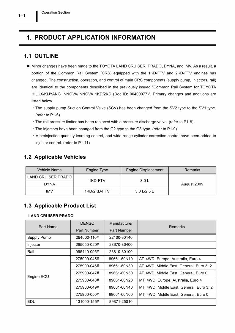
1.2 Applicable Vehicles
1.3 Applicable Product List
LAND CRUISER PRADO
Vehicle Name Engine Type Engine Displacement Remarks
LAND CRUISER PRADO1KD-FTV 3.0 L
August 2009DYNA
IMV 1KD/2KD-FTV 3.0 L/2.5 L
Part NameDENSO
Part Number
Manufacturer
Part NumberRemarks
Supply Pump 294000-110# 22100-30140
Injector 295050-020# 23670-30400
Rail 095440-095# 23810-30100
Engine ECU
275900-045# 89661-60N10 AT, 4WD, Europe, Australia, Euro 4
275900-046# 89661-60N30 AT, 4WD, Middle East, General, Euro 3, 2
275900-047# 89661-60N50 AT, 4WD, Middle East, General, Euro 0
275900-048# 89661-60N20 MT, 4WD, Europe, Australia, Euro 4
275900-049# 89661-60N40 MT, 4WD, Middle East, General, Euro 3, 2
275900-050# 89661-60N60 MT, 4WD, Middle East, General, Euro 0
EDU 131000-155# 89871-25010

Operation Section1–2
DYNA
Crankshaft PositionSensor
029600-143# 90919-05066
Camshaft PositionSensor
029600-116# 90919-05052
Accelerator PedalModule
198800-742# 78110-60030
Manifold AbsolutePressure (MAP) Sensor
079800-780# 89421-20200
Coolant TemperatureSensor
179700-045# 89422-33030
Intake Air TemperatureSensor
071500-237# 89727-60010
Exhaust GasRecirculation (EGR)Valve
101397-123# 25800-30190
Part NameDENSO
Part Number
Manufacturer
Part NumberRemarks
Supply Pump 294000-070# 22100-30090 SCV: 294200-004#
Injector
295050-007# 23670-30380 Different connector, for use with cylinders 1and 2
295050-008# 23670-30390
Rail 095440-095# 23810-30100
Engine ECU
275900-053# 89661-25290MT, 2WD, Europe, Euro 4 (C/D), withcharging regulation when starting
275900-054# 89661-25300MT, 2WD, Europe, Euro 4 (C/D), withoutcharging regulation when starting
EDU101310-570# 89870-25030
101310-581# 89870-25040
Crankshaft PositionSensor
029600-143# 90919-05066
Camshaft PositionSensor
029600-116# 90919-05052
Accelerator PedalModule
198300-302# 89281-35020
MAP Sensor 079800-780# 89421-20200
Coolant TemperatureSensor
179700-045# 89422-33030
Intake Air TemperatureSensor
071500-237# 89727-60010
Part NameDENSO
Part Number
Manufacturer
Part NumberRemarks
Operation Section1–3
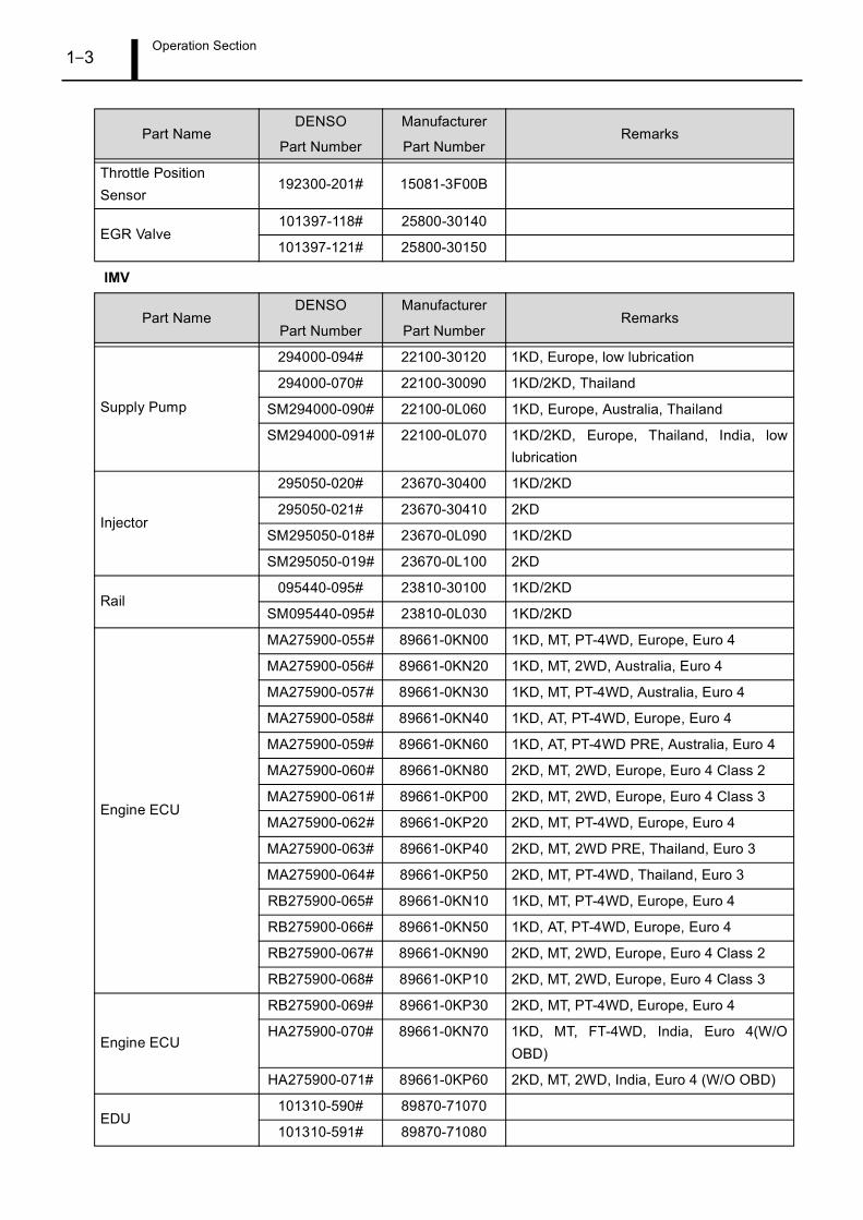
IMV
Throttle PositionSensor
192300-201# 15081-3F00B
EGR Valve101397-118# 25800-30140
101397-121# 25800-30150
Part NameDENSO
Part Number
Manufacturer
Part NumberRemarks
Supply Pump
294000-094# 22100-30120 1KD, Europe, low lubrication
294000-070# 22100-30090 1KD/2KD, Thailand
SM294000-090# 22100-0L060 1KD, Europe, Australia, Thailand
SM294000-091# 22100-0L070 1KD/2KD, Europe, Thailand, India, lowlubrication
Injector
295050-020# 23670-30400 1KD/2KD
295050-021# 23670-30410 2KD
SM295050-018# 23670-0L090 1KD/2KD
SM295050-019# 23670-0L100 2KD
Rail095440-095# 23810-30100 1KD/2KD
SM095440-095# 23810-0L030 1KD/2KD
Engine ECU
MA275900-055# 89661-0KN00 1KD, MT, PT-4WD, Europe, Euro 4
MA275900-056# 89661-0KN20 1KD, MT, 2WD, Australia, Euro 4
MA275900-057# 89661-0KN30 1KD, MT, PT-4WD, Australia, Euro 4
MA275900-058# 89661-0KN40 1KD, AT, PT-4WD, Europe, Euro 4
MA275900-059# 89661-0KN60 1KD, AT, PT-4WD PRE, Australia, Euro 4
MA275900-060# 89661-0KN80 2KD, MT, 2WD, Europe, Euro 4 Class 2
MA275900-061# 89661-0KP00 2KD, MT, 2WD, Europe, Euro 4 Class 3
MA275900-062# 89661-0KP20 2KD, MT, PT-4WD, Europe, Euro 4
MA275900-063# 89661-0KP40 2KD, MT, 2WD PRE, Thailand, Euro 3
MA275900-064# 89661-0KP50 2KD, MT, PT-4WD, Thailand, Euro 3
RB275900-065# 89661-0KN10 1KD, MT, PT-4WD, Europe, Euro 4
RB275900-066# 89661-0KN50 1KD, AT, PT-4WD, Europe, Euro 4
RB275900-067# 89661-0KN90 2KD, MT, 2WD, Europe, Euro 4 Class 2
RB275900-068# 89661-0KP10 2KD, MT, 2WD, Europe, Euro 4 Class 3
Engine ECU
RB275900-069# 89661-0KP30 2KD, MT, PT-4WD, Europe, Euro 4
HA275900-070# 89661-0KN70 1KD, MT, FT-4WD, India, Euro 4(W/OOBD)
HA275900-071# 89661-0KP60 2KD, MT, 2WD, India, Euro 4 (W/O OBD)
EDU101310-590# 89870-71070
101310-591# 89870-71080
Part NameDENSO
Part Number
Manufacturer
Part NumberRemarks
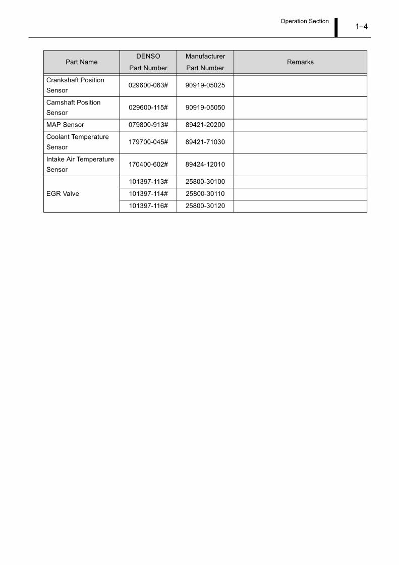
Operation Section1–4
Crankshaft PositionSensor
029600-063# 90919-05025
Camshaft PositionSensor
029600-115# 90919-05050
MAP Sensor 079800-913# 89421-20200
Coolant TemperatureSensor
179700-045# 89421-71030
Intake Air TemperatureSensor
170400-602# 89424-12010
EGR Valve
101397-113# 25800-30100
101397-114# 25800-30110
101397-116# 25800-30120
Part NameDENSO
Part Number
Manufacturer
Part NumberRemarks
Operation Section1–5
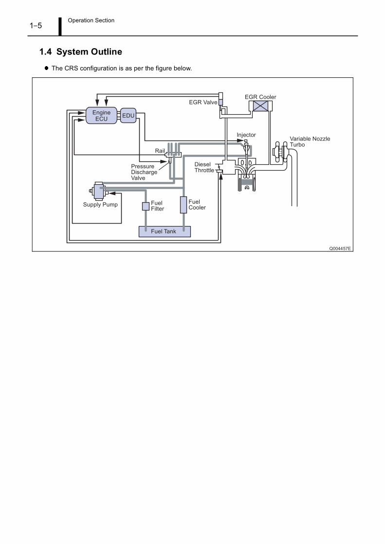
1.4 System Outline
The CRS configuration is as per the figure below.
Operation Section1–6
2. SUPPLY PUMP
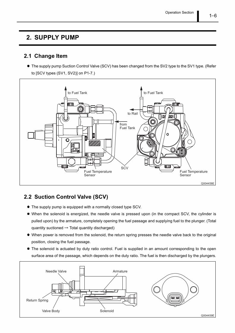
2.1 Change Item
The supply pump Suction Control Valve (SCV) has been changed from the SV2 type to the SV1 type. (Refer
to [SCV types (SV1, SV2)] on P1-7.)
2.2 Suction Control Valve (SCV)
The supply pump is equipped with a normally closed type SCV.
When the solenoid is energized, the needle valve is pressed upon (in the compact SCV, the cylinder is
pulled upon) by the armature, completely opening the fuel passage and supplying fuel to the plunger. (Total
quantity suctioned Total quantity discharged)
When power is removed from the solenoid, the return spring presses the needle valve back to the original
position, closing the fuel passage.
The solenoid is actuated by duty ratio control. Fuel is supplied in an amount corresponding to the open
surface area of the passage, which depends on the duty ratio. The fuel is then discharged by the plungers.
Operation Section1–7
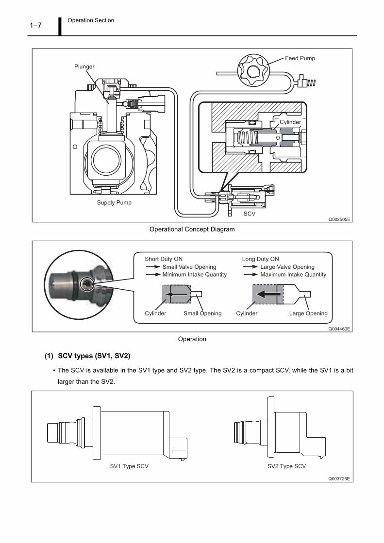
Operational Concept Diagram
Operation
(1) SCV types (SV1, SV2)
• The SCV is available in the SV1 type and SV2 type. The SV2 is a compact SCV, while the SV1 is a bit
larger than the SV2.

Operation Section1–8
3. RAIL
3.1 Change Item
Beginning from August 2006 model vehicles, a pressure discharge valve is used in place of the rail pressure
limiter. The engine ECU control and an actuation circuit (EDU) control the pressure discharge valve.
Operation Section1–9
4. INJECTOR
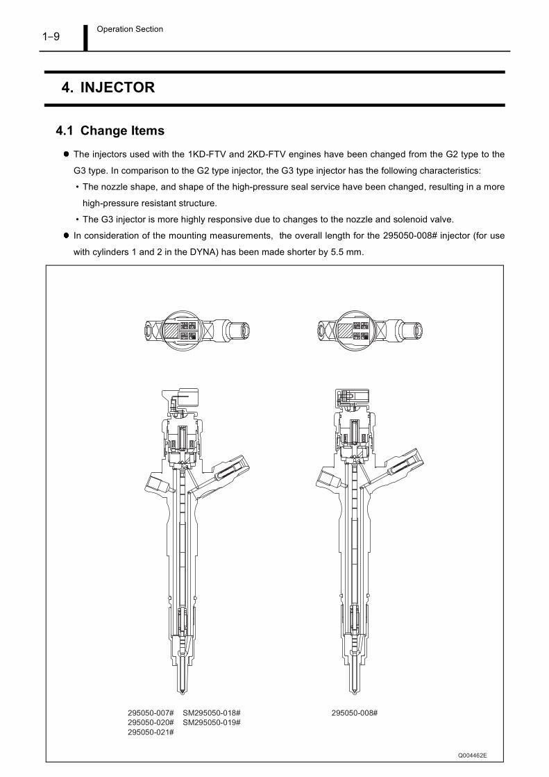
4.1 Change Items
The injectors used with the 1KD-FTV and 2KD-FTV engines have been changed from the G2 type to the
G3 type. In comparison to the G2 type injector, the G3 type injector has the following characteristics:
• The nozzle shape, and shape of the high-pressure seal service have been changed, resulting in a more
high-pressure resistant structure.
• The G3 injector is more highly responsive due to changes to the nozzle and solenoid valve.
In consideration of the mounting measurements, the overall length for the 295050-008# injector (for use
with cylinders 1 and 2 in the DYNA) has been made shorter by 5.5 mm.
Operation Section1–10
4.2 Quick Response (QR) Codes
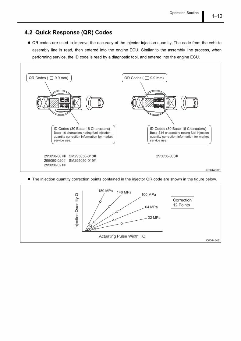
QR codes are used to improve the accuracy of the injector injection quantity. The code from the vehicle
assembly line is read, then entered into the engine ECU. Similar to the assembly line process, when
performing service, the ID code is read by a diagnostic tool, and entered into the engine ECU.
The injection quantity correction points contained in the injector QR code are shown in the figure below.
Operation Section1–11
5. FUEL INJECTION CONTROL
5.1 Change Item
Microinjection quantity learning control, and wide-range cylinder correction control have been added to the
CRS equipped with the 1KD-FTV and 2KD-FTV engines.
5.2 Injection Pattern
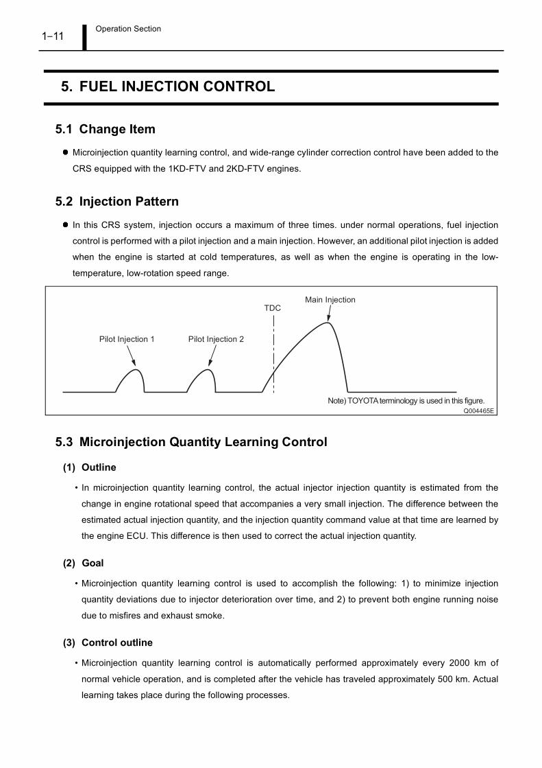
In this CRS system, injection occurs a maximum of three times. under normal operations, fuel injection
control is performed with a pilot injection and a main injection. However, an additional pilot injection is added
when the engine is started at cold temperatures, as well as when the engine is operating in the low-
temperature, low-rotation speed range.
5.3 Microinjection Quantity Learning Control
(1) Outline
• In microinjection quantity learning control, the actual injector injection quantity is estimated from the
change in engine rotational speed that accompanies a very small injection. The difference between the
estimated actual injection quantity, and the injection quantity command value at that time are learned by
the engine ECU. This difference is then used to correct the actual injection quantity.
(2) Goal
• Microinjection quantity learning control is used to accomplish the following: 1) to minimize injection
quantity deviations due to injector deterioration over time, and 2) to prevent both engine running noise
due to misfires and exhaust smoke.
(3) Control outline
• Microinjection quantity learning control is automatically performed approximately every 2000 km of
normal vehicle operation, and is completed after the vehicle has traveled approximately 500 km. Actual
learning takes place during the following processes.
Operation Section1–12
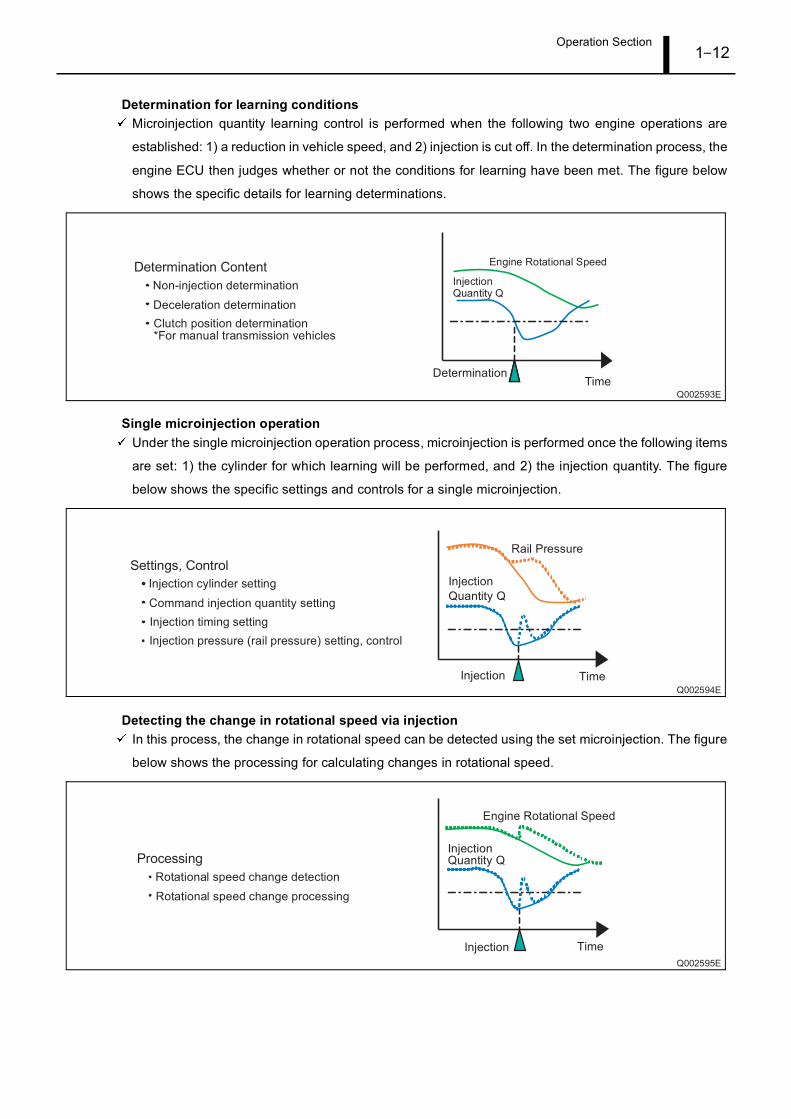
Determination for learning conditionsMicroinjection quantity learning control is performed when the following two engine operations are
established: 1) a reduction in vehicle speed, and 2) injection is cut off. In the determination process, the
engine ECU then judges whether or not the conditions for learning have been met. The figure below
shows the specific details for learning determinations.
Single microinjection operationUnder the single microinjection operation process, microinjection is performed once the following items
are set: 1) the cylinder for which learning will be performed, and 2) the injection quantity. The figure
below shows the specific settings and controls for a single microinjection.
Detecting the change in rotational speed via injectionIn this process, the change in rotational speed can be detected using the set microinjection. The figure
below shows the processing for calculating changes in rotational speed.
Operation Section1–13
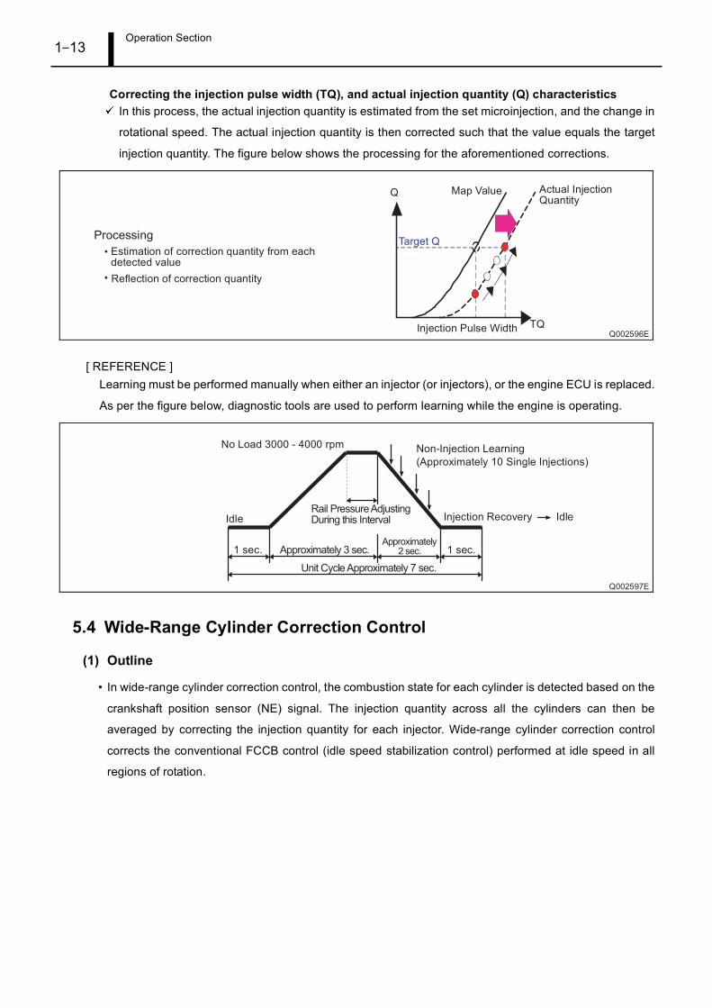
Correcting the injection pulse width (TQ), and actual injection quantity (Q) characteristicsIn this process, the actual injection quantity is estimated from the set microinjection, and the change in
rotational speed. The actual injection quantity is then corrected such that the value equals the target
injection quantity. The figure below shows the processing for the aforementioned corrections.
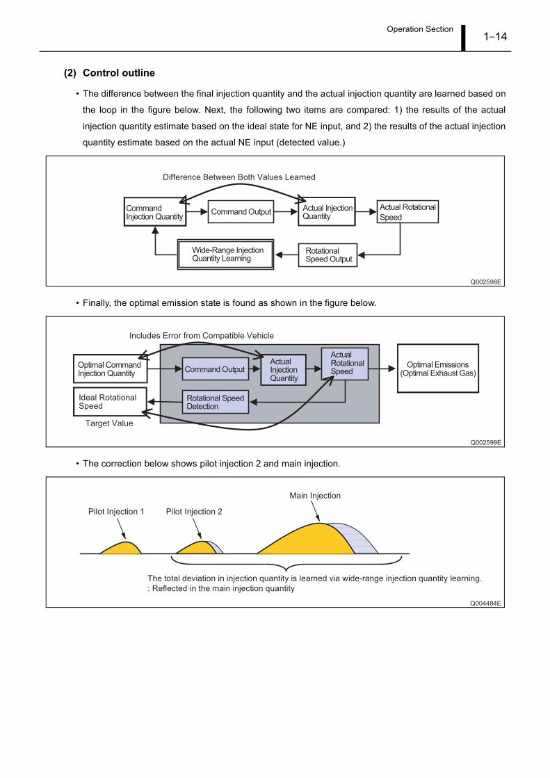
[ REFERENCE ]Learning must be performed manually when either an injector (or injectors), or the engine ECU is replaced.
As per the figure below, diagnostic tools are used to perform learning while the engine is operating.
5.4 Wide-Range Cylinder Correction Control
(1) Outline
• In wide-range cylinder correction control, the combustion state for each cylinder is detected based on the
crankshaft position sensor (NE) signal. The injection quantity across all the cylinders can then be
averaged by correcting the injection quantity for each injector. Wide-range cylinder correction control
corrects the conventional FCCB control (idle speed stabilization control) performed at idle speed in all
regions of rotation.
Operation Section1–14
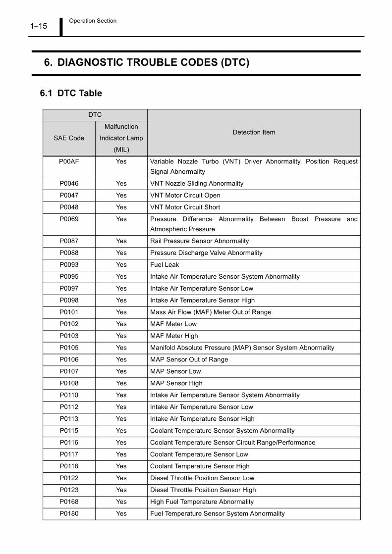
(2) Control outline
• The difference between the final injection quantity and the actual injection quantity are learned based on
the loop in the figure below. Next, the following two items are compared: 1) the results of the actual
injection quantity estimate based on the ideal state for NE input, and 2) the results of the actual injection
quantity estimate based on the actual NE input (detected value.)
• Finally, the optimal emission state is found as shown in the figure below.
• The correction below shows pilot injection 2 and main injection.
Operation Section1–15
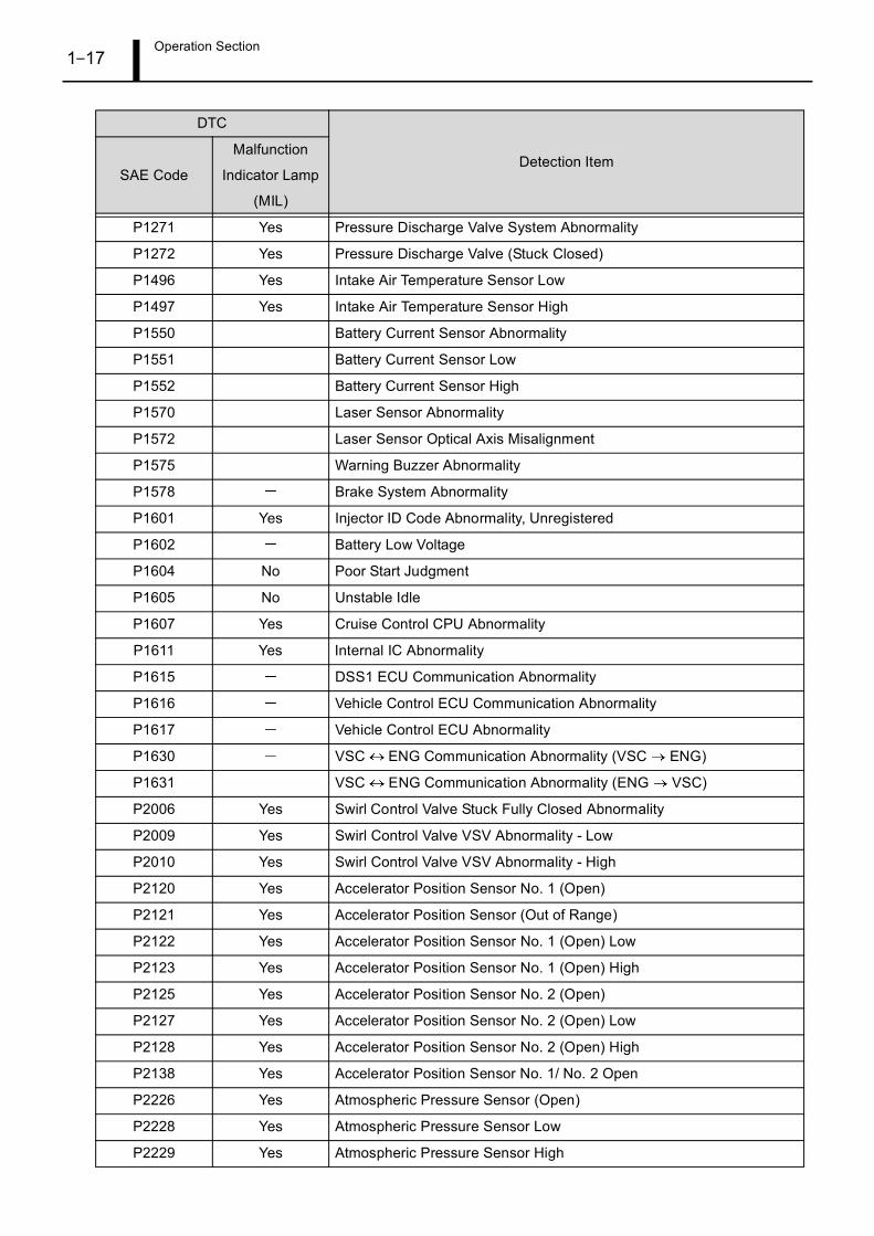
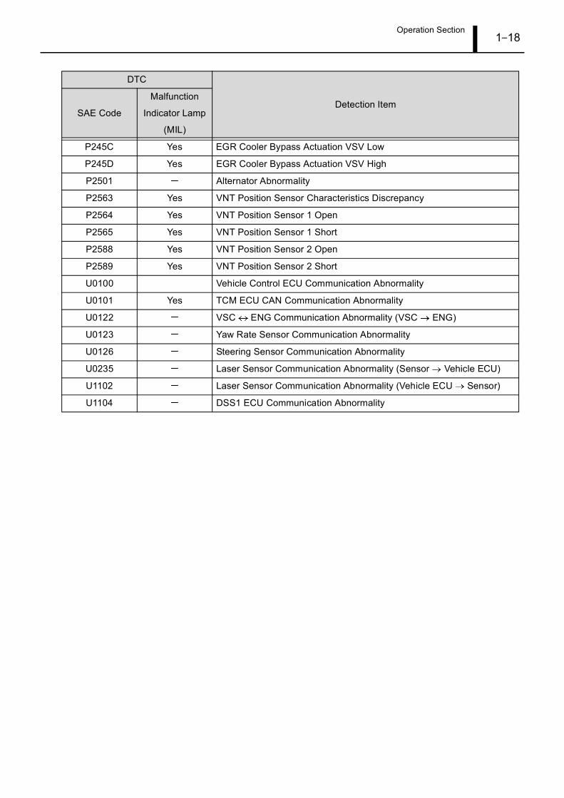
6. DIAGNOSTIC TROUBLE CODES (DTC)
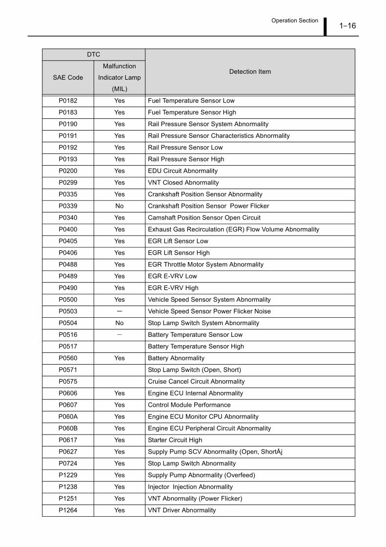
6.1 DTC Table
DTC
Detection ItemSAE Code
Malfunction
Indicator Lamp
(MIL)
P00AF Yes Variable Nozzle Turbo (VNT) Driver Abnormality, Position RequestSignal Abnormality
P0046 Yes VNT Nozzle Sliding Abnormality
P0047 Yes VNT Motor Circuit Open
P0048 Yes VNT Motor Circuit Short
P0069 Yes Pressure Difference Abnormality Between Boost Pressure andAtmospheric Pressure
P0087 Yes Rail Pressure Sensor Abnormality
P0088 Yes Pressure Discharge Valve Abnormality
P0093 Yes Fuel Leak
P0095 Yes Intake Air Temperature Sensor System Abnormality
P0097 Yes Intake Air Temperature Sensor Low
P0098 Yes Intake Air Temperature Sensor High
P0101 Yes Mass Air Flow (MAF) Meter Out of Range
P0102 Yes MAF Meter Low
P0103 Yes MAF Meter High
P0105 Yes Manifold Absolute Pressure (MAP) Sensor System Abnormality
P0106 Yes MAP Sensor Out of Range
P0107 Yes MAP Sensor Low
P0108 Yes MAP Sensor High
P0110 Yes Intake Air Temperature Sensor System Abnormality
P0112 Yes Intake Air Temperature Sensor Low
P0113 Yes Intake Air Temperature Sensor High
P0115 Yes Coolant Temperature Sensor System Abnormality
P0116 Yes Coolant Temperature Sensor Circuit Range/Performance
P0117 Yes Coolant Temperature Sensor Low
P0118 Yes Coolant Temperature Sensor High
P0122 Yes Diesel Throttle Position Sensor Low
P0123 Yes Diesel Throttle Position Sensor High
P0168 Yes High Fuel Temperature Abnormality
P0180 Yes Fuel Temperature Sensor System Abnormality
Operation Section1–16
P0182 Yes Fuel Temperature Sensor Low
P0183 Yes Fuel Temperature Sensor High
P0190 Yes Rail Pressure Sensor System Abnormality
P0191 Yes Rail Pressure Sensor Characteristics Abnormality
P0192 Yes Rail Pressure Sensor Low
P0193 Yes Rail Pressure Sensor High
P0200 Yes EDU Circuit Abnormality
P0299 Yes VNT Closed Abnormality
P0335 Yes Crankshaft Position Sensor Abnormality
P0339 No Crankshaft Position Sensor Power Flicker
P0340 Yes Camshaft Position Sensor Open Circuit
P0400 Yes Exhaust Gas Recirculation (EGR) Flow Volume Abnormality
P0405 Yes EGR Lift Sensor Low
P0406 Yes EGR Lift Sensor High
P0488 Yes EGR Throttle Motor System Abnormality
P0489 Yes EGR E-VRV Low
P0490 Yes EGR E-VRV High
P0500 Yes Vehicle Speed Sensor System Abnormality
P0503 Vehicle Speed Sensor Power Flicker Noise
P0504 No Stop Lamp Switch System Abnormality
P0516 Battery Temperature Sensor Low
P0517 Battery Temperature Sensor High
P0560 Yes Battery Abnormality
P0571 Stop Lamp Switch (Open, Short)
P0575 Cruise Cancel Circuit Abnormality
P0606 Yes Engine ECU Internal Abnormality
P0607 Yes Control Module Performance
P060A Yes Engine ECU Monitor CPU Abnormality
P060B Yes Engine ECU Peripheral Circuit Abnormality
P0617 Yes Starter Circuit High
P0627 Yes Supply Pump SCV Abnormality (Open, ShortÅj
P0724 Yes Stop Lamp Switch Abnormality
P1229 Yes Supply Pump Abnormality (Overfeed)
P1238 Yes Injector Injection Abnormality
P1251 Yes VNT Abnormality (Power Flicker)
P1264 Yes VNT Driver Abnormality
DTC
Detection ItemSAE Code
Malfunction
Indicator Lamp
(MIL)
Operation Section1–17
P1271 Yes Pressure Discharge Valve System Abnormality
P1272 Yes Pressure Discharge Valve (Stuck Closed)
P1496 Yes Intake Air Temperature Sensor Low
P1497 Yes Intake Air Temperature Sensor High
P1550 Battery Current Sensor Abnormality
P1551 Battery Current Sensor Low
P1552 Battery Current Sensor High
P1570 Laser Sensor Abnormality
P1572 Laser Sensor Optical Axis Misalignment
P1575 Warning Buzzer Abnormality
P1578 Brake System Abnormality
P1601 Yes Injector ID Code Abnormality, Unregistered
P1602 Battery Low Voltage
P1604 No Poor Start Judgment
P1605 No Unstable Idle
P1607 Yes Cruise Control CPU Abnormality
P1611 Yes Internal IC Abnormality
P1615 DSS1 ECU Communication Abnormality
P1616 Vehicle Control ECU Communication Abnormality
P1617 Vehicle Control ECU Abnormality
P1630 VSC ENG Communication Abnormality (VSC ENG)
P1631 VSC ENG Communication Abnormality (ENG VSC)
P2006 Yes Swirl Control Valve Stuck Fully Closed Abnormality
P2009 Yes Swirl Control Valve VSV Abnormality - Low
P2010 Yes Swirl Control Valve VSV Abnormality - High
P2120 Yes Accelerator Position Sensor No. 1 (Open)
P2121 Yes Accelerator Position Sensor (Out of Range)
P2122 Yes Accelerator Position Sensor No. 1 (Open) Low
P2123 Yes Accelerator Position Sensor No. 1 (Open) High
P2125 Yes Accelerator Position Sensor No. 2 (Open)
P2127 Yes Accelerator Position Sensor No. 2 (Open) Low
P2128 Yes Accelerator Position Sensor No. 2 (Open) High
P2138 Yes Accelerator Position Sensor No. 1/ No. 2 Open
P2226 Yes Atmospheric Pressure Sensor (Open)
P2228 Yes Atmospheric Pressure Sensor Low
P2229 Yes Atmospheric Pressure Sensor High
DTC
Detection ItemSAE Code
Malfunction
Indicator Lamp
(MIL)
Operation Section1–18
P245C Yes EGR Cooler Bypass Actuation VSV Low
P245D Yes EGR Cooler Bypass Actuation VSV High
P2501 Alternator Abnormality
P2563 Yes VNT Position Sensor Characteristics Discrepancy
P2564 Yes VNT Position Sensor 1 Open
P2565 Yes VNT Position Sensor 1 Short
P2588 Yes VNT Position Sensor 2 Open
P2589 Yes VNT Position Sensor 2 Short
U0100 Vehicle Control ECU Communication Abnormality
U0101 Yes TCM ECU CAN Communication Abnormality
U0122 VSC ENG Communication Abnormality (VSC ENG)
U0123 Yaw Rate Sensor Communication Abnormality
U0126 Steering Sensor Communication Abnormality
U0235 Laser Sensor Communication Abnormality (Sensor Vehicle ECU)
U1102 Laser Sensor Communication Abnormality (Vehicle ECU Sensor)
U1104 DSS1 ECU Communication Abnormality
DTC
Detection ItemSAE Code
Malfunction
Indicator Lamp
(MIL)
Operation Section1–19
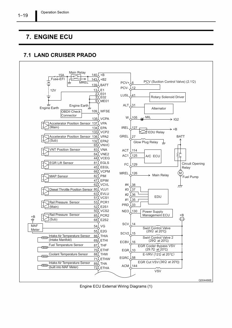
7. ENGINE ECU
7.1 LAND CRUISER PRADO
Engine ECU External Wiring Diagrams (1)
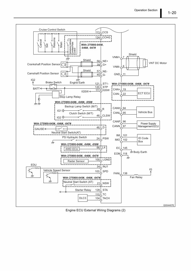
Operation Section1–20
Engine ECU External Wiring Diagrams (2)
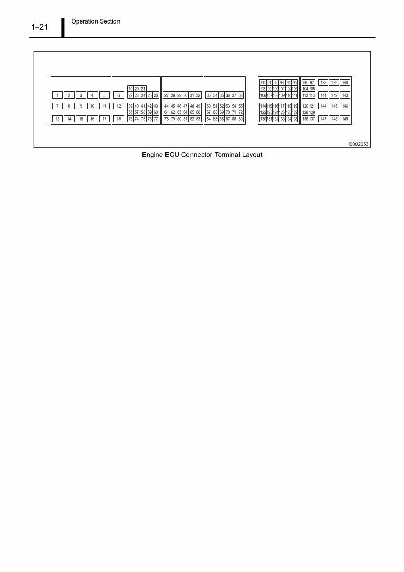
Operation Section1–21
Engine ECU Connector Terminal Layout
Operation Section1–22
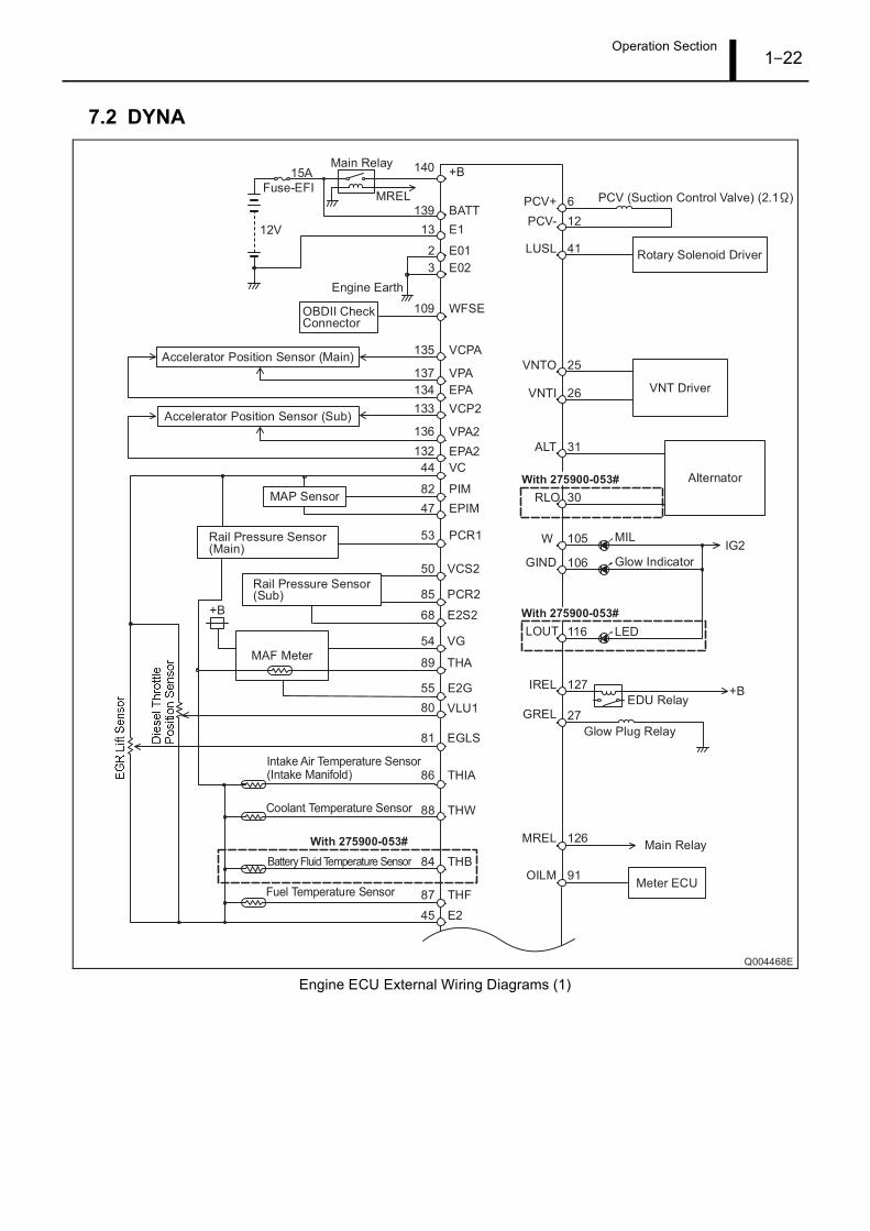
7.2 DYNA
Engine ECU External Wiring Diagrams (1)
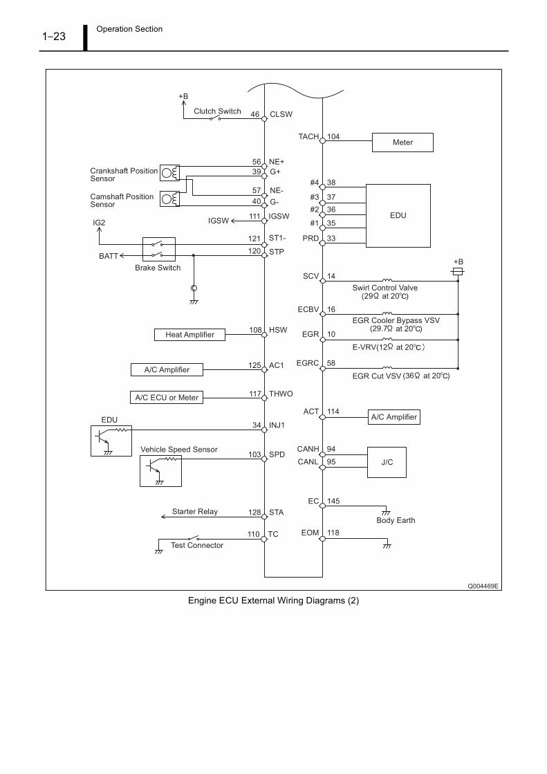
Operation Section1–23
Engine ECU External Wiring Diagrams (2)
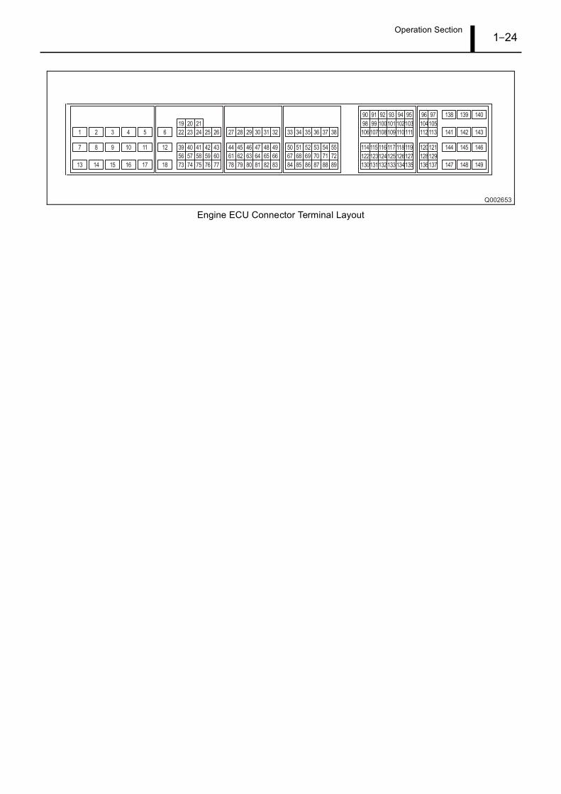
Operation Section1–24
Engine ECU Connector Terminal Layout

Operation Section1–25
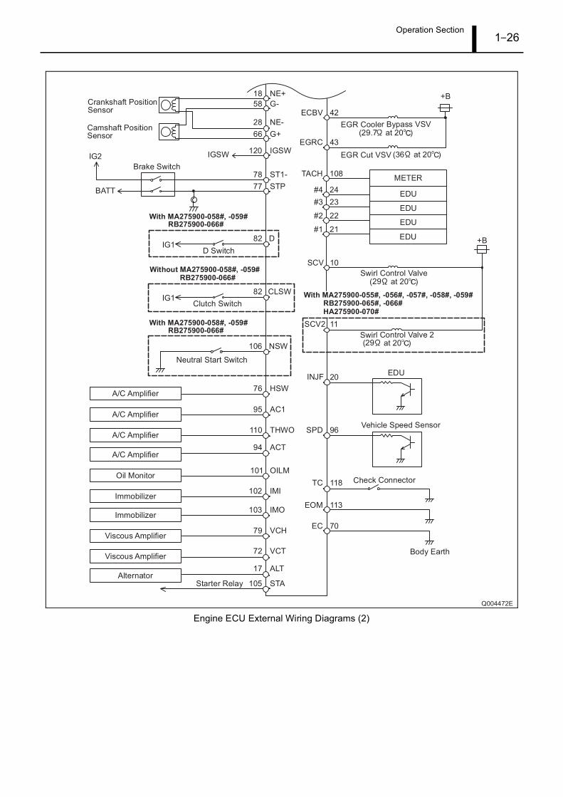
7.3 IMV
Engine ECU External Wiring Diagrams (1)
Operation Section1–26
Engine ECU External Wiring Diagrams (2)
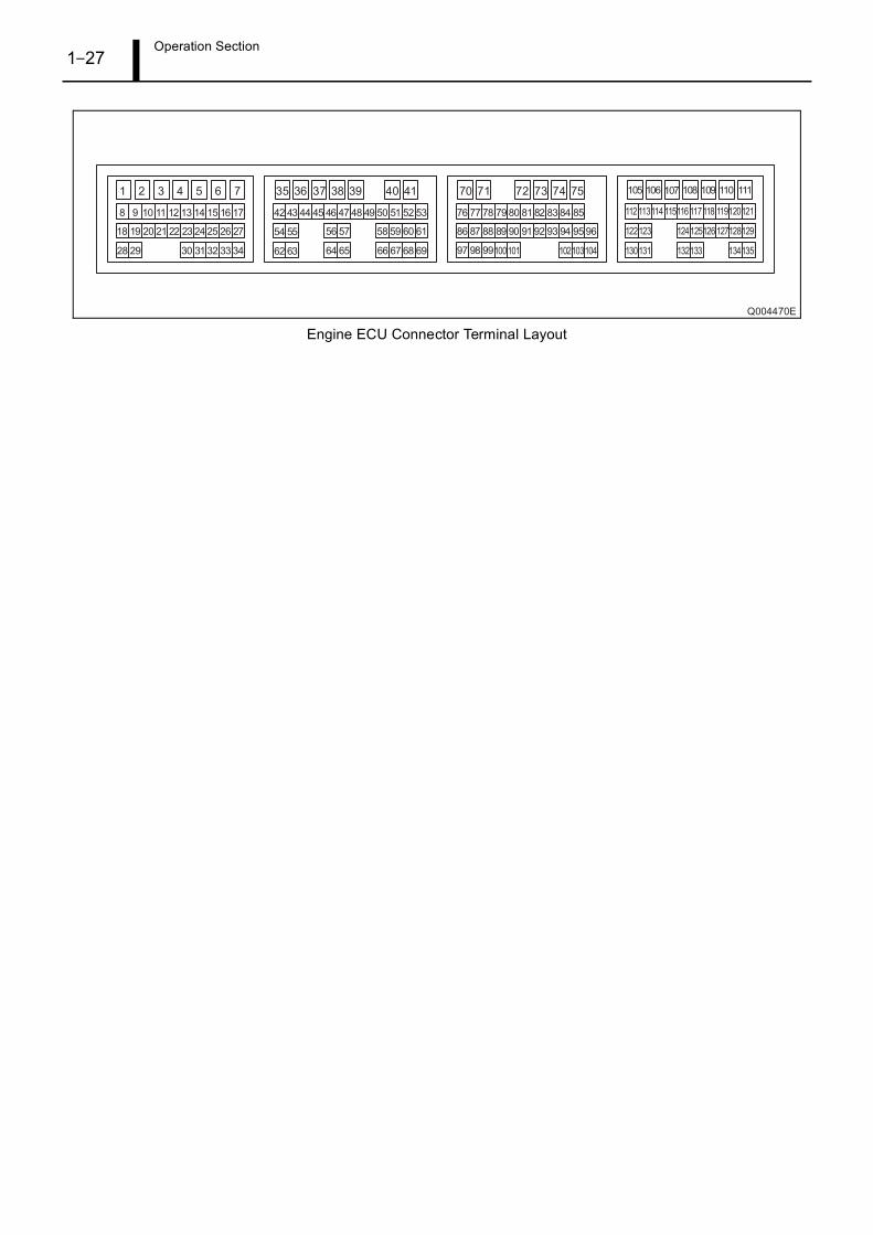
Operation Section1–27
Engine ECU Connector Terminal Layout

Service Department DENSO CORPORATION1-1, Showa-cho, Kariya-shi, Aichi-ken, 448-8661, Japan