multi-function intelligent electronic device ben6000 · · 2018-01-26multi-function intelligent...
TRANSCRIPT

Multi-function Intelligent Electronic Device BEN6000
Ultimate in the field of high voltage monitoring, the BEN6000 can easily spread its measurement points throughout your high voltage universe. Grouped into one structure, it shines by its accuracy, and the variety of measurements and sizes one can configure it for. • Multi-Function (DFR, DSM, Cont. Rec, PQM)
• 16-bit data acquisition at 10 or 12 kHz
• Triggered (2 speeds) + continuous recordings
• Centralised, decentralised1) architecture
• Standardised IEC 61850 communications
• Up to 192 Analog inputs and 384 Digital inputs
• Up to 200 Derived quantities (virtual channels)
General
Measuring System
Revolving around a powerful multi-tasks and real time operating system embedded in its core, the easily distributed architecture allows the complete overview of a high voltage environment from a single, extremely dependable and accurate, stand point.
A distributed Digital Fault Recorder with state-of-the-art resolution (16bits) and accuracy (0.1%) can be deployed with minimal intrusion and maximum communication into the protection panels (Remote Acquisition Units for 8 voltages and 16 Digitals are as small as 89mm (3.5”) high). The system channel capacity allows the monitoring of the widest applications.
A compact Dynamic Swing Monitor allows the combination of any inputs to create derived quantities2) to trigger long duration records for system stability or power flow analysis or generator monitoring.
A Continuous Recorder providing more than one month worth of recording independently from eventual triggering conditions.
A comprehensive Power Quality Monitor elaborating and compiling the Power Quality profile of the connected signals and offering them for restitution in a standardised fashion. The BEN cross triggering capability allows fast (DFR) and/or slow (DSM) signals recordings to happen upon a PQ event, significantly easing identification of its origin.
1) Up to maximum 3 km 2) Derived quantities may be recorded by the fast DFR and/or slow DSM and/or Continuous
Recording functions
Application examples
• Single feeder monitoring (BEN6000)
Speed Signals Triggers Comments Fast Analog 3U & 3I, V0 >I, <U, V0, Fast Dig. Brkr pos,
Prot. trip Dig Edge or level
Line fault
Slow Analog
P, Q, F, Urms
dP/dt, dQ/dt, dF/dt, Freq, <U
Slow Dig. Bkr pos. Prot. trip
Prot. trip
Continuous Recording
P, Q, Urms
System collapse, Swing, Power flow monitor. Proof of service
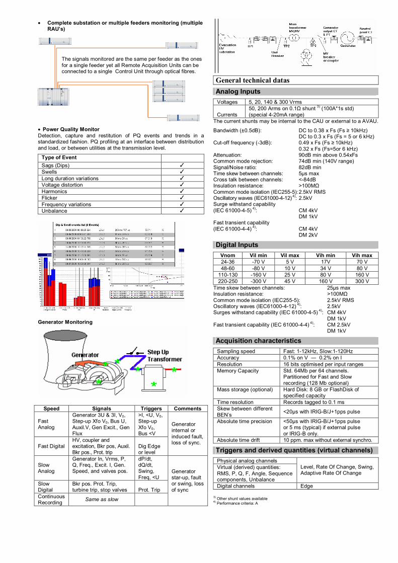
• Complete substation or multiple feeders monitoring (multiple RAU’s)
The signals monitored are the same per feeder as the ones for a single feeder yet all Remote Acquisition Units can be connected to a single Control Unit through optical fibres.
• Power Quality Monitor Detection, capture and restitution of PQ events and trends in a standardized fashion. PQ profiling at an interface between distribution and load, or between utilities at the transmission level.
Type of Event Sags (Dips) Swells Long duration variations Voltage distortion Harmonics Flicker Frequency variations Unbalance
Generator Monitoring
Speed Signals Triggers Comments
Fast Analog
Generator 3U & 3I, V0, Step-up Xfo V0, Bus U, Auxil.V, Gen Excit., Gen Flux
>I, <U, V0, Step-up Xfo V0, Bus <V
Fast Digital HV, coupler and excitation, Bkr pos, Auxil. Bkr pos., Prot. trip
Dig Edge or level
Generator internal or induced fault, loss of sync.
Slow Analog
Generator In, Vrms, P, Q, Freq., Excit. I, Gen. Speed, and valves pos.
dP/dt, dQ/dt, Swing, Freq, <U
Slow Digital
Bkr pos. Prot. Trip, turbine trip, stop valves
Prot. Trip
Continuous Recording Same as slow
Generator star-up, fault or swing, loss of sync
General technical datas
Analog Inputs
Voltages 5, 20, 140 & 300 Vrms Currents
50, 200 Arms on 0.1Ω shunt 3) (100A*1s std) (special 4-20mA range)
The current shunts may be internal to the CAU or external to a AVAU.
Bandwidth (±0.5dB): DC to 0.38 x Fs (Fs ≥ 10kHz) DC to 0.3 x Fs (Fs = 5 or 6 kHz) Cut-off frequency (-3dB): 0.49 x Fs (Fs ≥ 10kHz) 0.32 x Fs (Fs=5or 6 kHz) Attenuation: 90dB min above 0.54xFs Common mode rejection: 74dB min (140V range) Signal/Noise ratio: 82dB min Time skew between channels: 5µs max Cross talk between channels: <-84dB Insulation resistance: >100MΩ Common mode isolation (IEC255-5): 2.5kV RMS Oscillatory waves (IEC61000-4-12) 4): 2.5kV Surge withstand capability (IEC 61000-4-5) 4): CM 4kV DM 1kV Fast transient capability (IEC 61000-4-4) 4): CM 4kV DM 2kV
Digital Inputs
Vnom Vil min Vil max Vih min Vih max 24-36 -70 V 5 V 17V 70 V 48-60 -80 V 10 V 34 V 80 V
110-130 -160 V 25 V 80 V 160 V 220-250 -300 V 45 V 160 V 300 V
Time skew between channels: 25µs max Insulation resistance: >100MΩ Common mode isolation (IEC255-5): 2.5kV RMS Oscillatory waves (IEC61000-4-12) 4): 2.5kV Surges withstand capability (IEC 61000-4-5) 4): CM 4kV DM 1kV Fast transient capability (IEC 61000-4-4) 4): CM 2.5kV DM 1kV
Acquisition characteristics
Sampling speed Fast: 1-12kHz, Slow:1-120Hz Accuracy 0.1% on V ― 0.2% on I Resolution 16 bits optimised per input ranges Memory Capacity Std. 64Mb per 64 channels.
Partitioned for Fast and Slow recording (128 Mb optional)
Mass storage (optional) Hard Disk: 8 GB or FlashDisk of specified capacity
Time resolution Records tagged to 0.1 ms Skew between different BEN’s <20µs with IRIG-B/J+1pps pulse
Absolute time precision <50µs with IRIG-B/J+1pps pulse or 5 ms (typical) if external pulse or IRIG-B only.
Absolute time drift 10 ppm. max without external synchro.
Triggers and derived quantities (virtual channels)
Physical analog channels Virtual (derived) quantities: RMS, P, Q, F, Angle, Sequence components, Unbalance
Level, Rate Of Change, Swing, Adaptive Rate Of Change
Digital channels Edge
3) Other shunt values available 4) Performance criteria: A
• Threshold resolution: 0.1% • Tpost 0.02 to 1300s (resolution: 10ms) • Tmax 0.05 to 3000s (resolution: 10ms) • Tinhibit 0 to 24h (resolution: 10ms) • Rate of change Time window: 10 to 1000ms
RMS value: Accuracy: see analog input, Response time: 60ms typ Frequency: Range: ±8Hz around nominal value Accuracy: 2mHz (±2Hz around nominal value) Response time: 240ms min (adjustable) Power (dP/dt, dQ/dt): Accuracy: 0.4% Response time: 40ms typ Phase angle: (only in DSM mode) Accuracy: 0.1° Response time: 175ms typ Zero-sequence: Accuracy: 0.15% on voltage inputs, 0.25% on current
inputs Response time: 50ms typ Positive/Negative sequence: Accuracy: 0.2% on voltage inputs, 0.3% on current
inputs Response time: 60ms typ Unbalance: Accuracy: 0.25% on voltage inputs, 0.35% on current
inputs Response time: 60ms typ
Other triggers available with PQ Card (harmonics, …) Continuous recording
Capture of a selection of virtual channels in ultra slow recording (hard or flash disk is mandatory for this option) Input / outputs
Modulated IRIG-B/J, pulse Serial IRIG-J + 1pps in Real time clock synchro Synch pulse input
i/o PC direct EIA-232, USB i/o Modem V 24 i/o Ethernet 10Base-FL, 100Base-FX out Printer Centronics
Isolation resistance: >100MΩ Common mode isolation: 1kV RMS Fast transient capability (IEC61000-4-4): CM 2kV Ethernet: 10Base-FL or 100-BaseFX,
Effective throughput: 100KB/s Synch pulse input: Vih: 15 or 80V, Twidth: 5ms min Period: 1, 5 or 15 min, 1 or 24 h
i/o Calibration 1 x EIA-232 per Acquisition controller. out Relays 8 potential free contacts (optional 8
additional)
Contacts rated (NO/NC): 250VRMS - 5A (resistive load), 110V – 0.5A DC Delay from start bus: 15ms Minimum alarm duration: 100ms Isolation resistance: >100MΩ Common mode isolation (IEC 255-5): 2.5kV RMS Oscillatory waves (IEC61000-4-12): 2.5kV Surges withstand capability (IEC61000-4-5): CM 4kV Fast transient capability (IEC61000-4-4): CM 2kV Power supply
Model Vin SENS 941-04 48 – 60 VDC SENS 941-01 110 – 220 VDC or 125 - 220 VAC
Tolerance on input voltage: ±20% Isolation resistance: >100MΩ Common mode isolation (IEC255-5): 2.5kV RMS Oscillatory waves (IEC61000-4-12) 4): 2.5kV
Conducted disturbances (IEC61000-4-6) 4): 10V/m Surges withstand capability (IEC61000-4-5) 4): CM 4kV DM 2kV Fast transient capability (IEC61000-4-4) 4: CM 4kV DM 2kV Electromagnetic emissions: EN 55011 class A
Environment
Operating: 5 to 55 degrees °C without disk 5 to 45 degrees °C with disk 5 to 40 degrees °C with battery option Storage: -10 to 65 degrees °C Humidity: 10 to 90% non-condensing Vibration (IEC 68-2-6): 4.9m/s2 Electrostatic discharge (IEC 61000-4-2) 4): class 4 Radiated Electromagnetic field (IEC 61000-4-3) : class 3 Hardware
Control Unit
Built on an industrial Compact PCI bus and one 250 MIPS CPU card. It exists in two versions:
Type Max. Channels Extension slots BEN6000 Standard 192 A / 384 D 6 BEN6000 Compact 64 A / 128 D 1
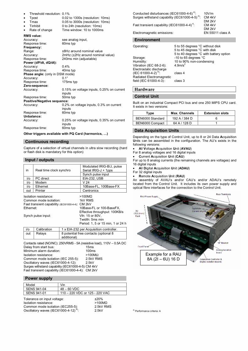
Data Acquisition Units
Depending on the type of Control Unit, up to 8 or 24 Data Acquisition Units can be assembled in the configuration. The AU’s exists in the following versions: • All Voltage Acquisition Unit (AVAU) For 8 analog voltages and 16 digital inputs • Current Acquisition Unit (CAU) For up to 8 analog currents (the remaining channels are voltages) and 16 digital inputs • All Digital Acquisition Unit (ADAU) For 32 digital inputs • Remote Acquisition Unit (RAU) An assembly of AVAU’s and/or CAU’s and/or ADAU’s remotely located from the Control Unit. It includes its own power supply and optical fibre interfaces for the connection to the Control Unit.
4) Performance criteria: A
Beispiel für eine RAUExample for a RAU 8A (2I – 6U) 16 D
Printed in EU Technical modifications reserved
Publication A24302E
Distributor:
www.qualitrolcorp.com
Qualitrol Company LLC Information Products Division Information Products Division1385 Fairport Road 15 Wildflower Way Avenue Newton 8 – Zoning Nord Fairport, NY 14450 Belfast 1300 Wavre USA Northern Ireland BT126TA BELGIUM Phone: +1 (585) 586-1515 Phone: +44 (0)2890-225200 Phone: +32 (0) 22 67 16 Fax orders: +1 (585) 377-0220 Fax: +32 (0) 22 69 98 Fax quotes : +1 (585) 377-9613 E-mail: [email protected]
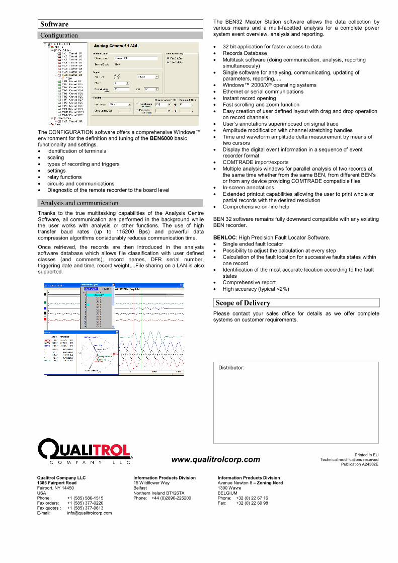
Software
Configuration
The CONFIGURATION software offers a comprehensive Windows™ environment for the definition and tuning of the BEN6000 basic functionality and settings. • identification of terminals • scaling • types of recording and triggers • settings • relay functions • circuits and communications • Diagnostic of the remote recorder to the board level
Analysis and communication
Thanks to the true multitasking capabilities of the Analysis Centre Software, all communication are performed in the background while the user works with analysis or other functions. The use of high transfer baud rates (up to 115200 Bps) and powerful data compression algorithms considerably reduces communication time.
Once retrieved, the records are then introduced in the analysis software database which allows file classification with user defined classes (and comments), record names, DFR serial number, triggering date and time, record weight,...File sharing on a LAN is also supported.
The BEN32 Master Station software allows the data collection by various means and a multi-facetted analysis for a complete power system event overview, analysis and reporting. • 32 bit application for faster access to data • Records Database • Multitask software (doing communication, analysis, reporting
simultaneously) • Single software for analysing, communicating, updating of
parameters, reporting, ... • Windows™ 2000/XP operating systems • Ethernet or serial communications • Instant record opening • Fast scrolling and zoom function • Easy creation of user defined layout with drag and drop operation
on record channels • User’s annotations superimposed on signal trace • Amplitude modification with channel stretching handles • Time and waveform amplitude delta measurement by means of
two cursors • Display the digital event information in a sequence of event
recorder format • COMTRADE import/exports • Multiple analysis windows for parallel analysis of two records at
the same time whether from the same BEN, from different BEN’s or from any device providing COMTRADE compatible files
• In-screen annotations • Extended printout capabilities allowing the user to print whole or
partial records with the desired resolution • Comprehensive on-line help BEN 32 software remains fully downward compatible with any existing BEN recorder. BENLOC: High Precision Fault Locator Software. • Single ended fault locator • Possibility to adjust the calculation at every step • Calculation of the fault location for successive faults states within
one record • Identification of the most accurate location according to the fault
states • Comprehensive report • High accuracy (typical <2%) Scope of Delivery
Please contact your sales office for details as we offer complete systems on customer requirements.