mtrb library - ship structure · 2006-04-25 · progress report on correlation of laboratory tests...
TRANSCRIPT

PROGRESS REPORT
ON
CORRELATION OF LABORATORY TESTS WITHFULL SCALE SHIP PLATE FRACTURE TESTS:
A STUDY OF STRAIN GRADIENTS
BY
E.P.KLIER F.C.WAGNER,J.L.FISHERandM. GENSAMER
Penn.wlvaniaStateCollegeUnderBureauofShipsContractNObs-31217
COMMITTEEON SHIPCONSTRUCTION
DIVISIONOF ENGINEERINGAND INDUSTRIALRESEARCH
NATIONALRESEARCHCOUNCIL
MTRB LIBRARY
ADVISORYTO
SHIP STRUCTURE COMMITTEE
UNDER
BureauofShips,NavyDepartmentContractNObs-34231
SERIAL NO. SSC-17
COPY NO. .! ‘.?.. .
DATE:JUNE 8,1949

CABLEADDRESSNARECO. W..hi.@o.. D. C.
NATIONAL RESEARCH COUNCIL2101CONSTITUTION AVENUE, WASHINGTON, D.C.
E.t.bli.h.d in 1916by th? h,.ti..al A.wlmm’of science,underits Conmsd.n.lCharterand Wzanizedwith the Cmmraticmof the Natimml?=i..tific
and TechnicalWcietksof the united Sites
DIVISIONOF ENGINEERINGAND INDUSTRIALRESEARCH
Jone 8.1S49
Chief,Bureauof ShipsWfy DepartmentWashington2.5,D. C.
De&r Sir:
Attaohedis ReportSerialifo.SS-17,entitlednCorrelationof LaboratoryTestswith Full %ale ShipPlateI’raoturel!eete:A Studyof StrainGradiente.” Thie reporthes beensubmittedby the oontraotorae a ProgreesReportofthe work done on ResearohProjeotSR-96underContre,otNObe-31217betweenthe Bureauof Ships,Navy Departmentand PennsylvaniaStateCollege.
?he reporthas been reviewedand aooeptancerecom-mendedby representativesOf the COmmitteeon ship CO~truotion~Divieionof Engineeringand IndustrialRessarch,FRC, Inamordance with the texmeof the contractbetweenthe Bureauof Shipe,Mavy Departmentat the NationalAoademyof fbi~oee.
CRS:mhEnoloeure
~/~::2
9C. RichardSoderberg,ChairmanDivisionof EngineeringandIndustrialResearoh

PREFACE——
The NavyDepartmentthroughthe Bureauof Ships is distributingthis reportto thoseagenciesand individualswho”were actively,associatedwith the researchwork, This reportrepresentsa part of the researchwork contractedfor underthe sectionof the Navy!sdirective‘Ito investigatethe designand constructionof weldedsteelmerchantvessels.11
The distrfoutionof thisreportis as ?O11OWS:
CopyNo. 1 - Chief,Bureauof Ships,Navy DepartmentcopyNo. 2 - Dr. D. W. Bronk,Chairman,NationalResearchCouncil
Committeeon Ship Construction
copy No. 3 ,-V. H. Schnee,ChairmanCopy ~!O. 4- J. i.’BatescopyNo. 5 - H. C. BoardmanCopy No. 6 - Paul FfieldcopyNo. 7 - M. A. GroesmanCopyNo. 8 - C. H. Herty,Jr.Copy No. 9 - A. B. KinzelCopyNo. 10,.-J. M. Lessens ~‘copyEo. U -”G. S. MikhalapovCopy No. 12.- J. Ormondroyd ‘“copy No. 13 - H. W. PierceCopy No. U - E. C. SmithCOPY IIOe 15 - T. T. I!atsonCOTJ No. 16 . Finn Jonaseen,ResearchCoordinator
Membe:-sof ProjectAdvisoryCommitteesSR-25,SFi-f?7,SR-92,SR-96,SR-98,SR-99,SR-1OOand S%101
COPY No. 16 - Finn Jonassen,Chairmencopy NO. 17 - R. H. AbornCopyNo. 18 - L. C. Blbbercopy No. 5 - H. C. Boardmencopy 1?0. 19 - T. J. DolanCopy No. 6- Paul.Ffieldcopy No. 7 - M.’”A.Grossman “.CopyNO. 8 - C. H. Herty,Jr.
,.,,,.’
copy }?0. 20 - C. E. ~aOkStlIl
copyNo. 10 - J. M. Lessens ,.
Cow No. 21 - M. W. Lightner. “
copy No. 11 - G. S. l!i~lialapovcopy No. 12 - J. OrmondroydcopyNo. 22 - R. E. PetersonCopyNo. 13 - H. W. Piercecol?y NO. 23 - R. L. RickettCOpyNO. 14 - E. C.’SmithcopyNo. 15 - T. T. EatsonCOPY !{0. 24 - A. G. Bissell,Bureauof Ships,LiaisonCOpy1“’0.25 - MathewLetich,America:Bureauof Shipping,Liaison
-+???d%.—=—’—+$~ z~ “&; -; $.j-.;~u

COPy ]!0.26 - JamesI!lcIntosh,Ut S. OohstCiua,rd,LiaisonCOpy 1~0.27 -~ . . 4. J& -.~ -“~/@-LcopyNo. 28 - Comdr.R. D. Schmidtrnan,U. S, CoastGuard,LiaisoncOpY NO. 29 - ‘I. L. SOO-HOO,,Btu~eauof.Ships,Lia.j’soncopyNo. 30 - Wm. Spraragen,’WeldingResearchCouncil,LikisoncopyNo. 31 - R. E. Wiley,Bureauof Ships,I,iaj.s,onCOpy}~o.32 - J. L. Wilson,,@ericanBureauof Shipping,Liaison
Ship StructureCommittee
copy No. 33 - Rear AdmiralEllisReed-Hill,USCG - Chairmancopy1!0.34 - Rear AdmiralChs.rleeD.J!heelock,USN,Bureauof ShipscopyNo. 35 - BrigadierGeneralPaul J?.Yonnt,War DepartmentCOn7 No. 36 - Ca~tainJ. L. McGui~an.!J.S. ?:!aritimeCommissionco;> NO. 37 -copyN’o. 3 -
copy NO. 38 -copyro. 39 -copyNo. 40 -copy No. 28 -copyNO. 41 -COpY }?0.42 -COpYNo. 25 -COpy No. 26 -copyNo. 43 -copyNo. 44 -copy No. 31 -COpy !:0. 32 -COpy fro.16 -copy Ho. 45 -COpyNo. 46 -Copyi~o.30 -
D.’P. Brown,‘Americ~nBureau”of ShippingV, H. Schnee,Committeeon Ship Construction- Liaiaon
Ship St,ructmeSubcossnittee
CaptainC. M. Tooke,USN,Bureauof Ships,ChairmancaptainR. A. Hinners,lJSN,DavidTaylorModelBasinComdr.R. H. Lambert,USN, Bureauof ShipsComdr.R. D. Schmidtman,USCG,LT.S.CoastGuardHeadquartersW, G. Frederick,U. S. MaritimeCommissionFubertKempel,Ofiiice,Chiefof Transportation?War DepartmentMa.thewLetich,AmericanBureauof ShippingJamesIicIntosh,U. S. CoastGuardR. M. Robertson,Office,l’avalResearch,U. S. NavyV, II.Russo,U.,S. MaritimeCommissionp, Z. WileY,Bureauof Ships,U. S. NavyJ. L. Wilson,AmericanRureauof ShippingFinn Jonassen,LiaisonRepresentative,NRCE. H. Davidson.LiaisonRepresentative,AISIPaul Gerhart,~iaisonRepr&sentative,AISIwm. Spraragen,LiaisonRepresentative,~JRC
Navy Department
copy1!0.f+7- Comdr.R. S. Mandelkorn,LEiT,ArmedForcesCopyNo. 24 - A. G. Bissell,Bureauof Shipacopy NO. 48 - A. Amirikian,BureauOf Yards and DOcksCODY!?0. L9 - J. T. Jenkino,Bureauof ShipsCo;yNo. 50-copyNo. 51 -COpy No. 52 -copy NO. 53 -copy NO. 54 -Copies55 andcopy NO. 57 -cOpy NO. 58 -Copyi!o.59 -copyNo. 60 -
NoahKahn,lte~York NavalShipyardE. ii.MacCutcheon,Jr., DavidTaylorModelIT.R. Osgood,DavidTaylorModelBasinN. E. Promisel,Bureauof AeronauticsJohn Vasta.Bureauof Ships
Special“PieaponsProject
Basin
56 - U. S.”FavalEngineeringExperimentStationNew York XavalShipyard,MaterialLaboratoryIndustrialTeeti.ngLaboratory,PhiladelphiaNavalShipyardPhiladelphiaNayalShipyardSan FranciscoNavalShipyard

copyNO. 61 -David ~aylorModelBasin,Attn:Libra~Copies62 and 63 .-PublicationsBoard,Navy llepartrientvia RuShips,Code 330cCopiee&+ and 65 - T’ecbnicalLibrary,Bureauof Ships,Code 337-L
U. S,,Cpait”G&-d
Copy No. 66 -copy No. 67 -copy1?0.6s -COPyNO. 69 -
copy No, 70 -
CopyNo. 71 -
CopyNo. 18 -
copy No. 8 -copy No. IA -
COpy No. 72 -copyNo, 73 -
Copy1!0.75 -co~y i!O. 8 -cOpy NO. 76 -copy No. 77 -copy No. 7$3-copy WO. 79 -COPy No. 80 -CopyNo. 21 -copy No. 81 -COpy NO. 16 -copy Ho. 82 -
CaptainR. B. Lank,,Jr..,USCGCapta+nG. A. Tyler,I$3CGTestingand D,evslopmeqtDivision,U. S. CoastGuardAca+emy,New London
,,U. S. MaritimeConimi3sion
E. E. Martinsky
Representativesof AmericanIronand Steel InstituteCommitteeon ManufacturingProblems
C. M.
L. C.C. H.3. c.
C> A.
Parker,Secreta~’,GeneralTe@nical Committse,AmericanTronand SteelInstituteBibber.Garnegie-IllinoisSteelCorD.Herty,“Jr.,B&,lilehemSteel~ompany”.%iith,,RepublicSt@l Company
WeldingReeearch.?~uncil
Adama CODYiio.7LIiierettChapman Co;f No: 36
Committeeon ShipSteel
P.,F. MehljChairmenC. H. Herty,Jr., Vice ChairmanWm. M. Baldwin,Jr.Chas.S. BarrettR.,11.BrickS. L, HoytI. R. KramerM, W. LightnerT. S. WashburnFinn Jonassen,TechnicalDirectorR, H. Rari.ngjTechnicalSecretary
- LaMotteGrover. Wn. Spraragen
Copy ITo.83 - C. R. Soderberg,Chairman,Div.Eng.& Ind.Research,NRCCopy No. 3 - V. R. Schnee,Chairman,Committeeon Ship Constructioncopy No. 16 - Finn .lonassen,ResearchCoordinator,Committeeon Ship ConstructionCOpy NO. 84 - E. P. Klier,Investigator,ResearchProjectSR-96COpy No. 85 - F. C. Wagner,Investigator,ResaarchProjectSR-96copy Noe 86 - J. L. Fisher,Investigator,ResearchProjectSR-96COPY No. 87 - 11.Gensamer,Inveetiga.tor,ResearchProjectSR-96Copy ~iO. 88 - S. T. Carpenter,Investigator,ResearchProjectSR-% .”copy NO. 89 - L. J. Ebert,Investigator,ReeearchProjectSR-99copy No. 10 - J. U. Lessens, Investigator,ResearchProjectS~-101
—. —

copy No. ‘Y1- C. W. MacGre&or,Investigator,ResearchF’rejectSI?-102CopyNo. 91 - C~ B. Voldrich,Investigator,ResearchProjectSR-1OO ‘.COPYNO. 92 - ClarenceAltenburger,GreatLikesSteelCompanycopy No. 93 - A. B. Eagsa,r,Suu Oil CompanycopyNo. 94 - E. L. Cochrane,MassachusettsIneti.tuteof Technol.oflJcopy No. 95- GeorgeEllinger,NationalBureauof StandardsCOpY ~~0.96- M. F, Hawkes.CarneRieInstitute”of Technolom
Low,”Jr.j GeneralElect>icCompanyNewmark,Un5.versityof IllinoisNorton,MassachusettsInstituteof TechnologyReich,GeneralElectricCompanyRohl,Carnegie-IllinoisSteelCorp.Roop,SwarthmoreCollegeStout,LehighUniversity
Copj NO. 9’7- W. F. Hess,fieneeel~erPo~ytechr,icInetitute--CopyNo. ‘3$3- 0. J. Horger,Timken RollerBearingCompanycopy No. 99 - Bruce JOhDS ton, Frit ?, Laboratory,’;Lei~ighUnj.versity ,copyNo. 100 - P. E. Kyle,CornellUniversityCopy No. 101 - J. R.copyNo. 102 - N, M,Copy No. 103 - J. T.Copy No. 10L - W. A.CopyNo, 105 - L. J.COpy NO. 106 - W. P.CopyNo. 107 - R. D.copy NO. 108 - SaylorSnyd&, Ca&e.gie-Illin~iaSteelCorp.CopyNo. 109 - J. F. Wal.laoe,WatertownArsenallaboratory (staff)copy No. 110 thru 134 - Sir Chas.Wright,British.Toint,.ServicesMiesion(NavjJcopy No. 135 - Carl A. Zapffe, CarlA, ,ZapffeLaboratoriesGOpyNO. 136 - InternationalNickelCo., Ino.,Attn: ‘f.F. ,ArmstrongCopyNo. 137 - TransportationCorpsBoard,Brooklyn,New YorlcCopies138 tbru 142 - Libraryof“Congresa”via Bureauof Ships,Code 330cCopyI!oJ L!+:- File Copy,Committeeon Ship Steelcopyno.“l&+- NACA,Attn: ,Ma~erialsResearchCoordination,U. S. ~avyCopiesU5 thru 149 - Bureaiif Sh;ps
‘::=v+;_:~y&’ %4copy No. 150 -
%%%: :% -4. ~ - C.&+-AQ-n L+A+LJJ%z.:f+copyNO. 153 -&v da% %6 %+Q&@zz d/J’h-q .copy No. 154 - ~.~.M\LLGQ-CA-V=V@@M r.c+aw ea. f,. ~ +( ’.>-=
Copy No. 155 ..-0...D .~ c1.u.jx$copy No. 155 -Copy No. 156 - -copy 1!0.157 -
~-.,&=&’-& - * -i. -.<-~3
copyNo, 15s -CopyNo. 159 -copy No. 160 -COPY 170. 161 - ,,COPYFO. 162 -COpy,No. 163 -COpy No, 16A -CopyNo. 165 -copyNO. 166,,-.COpyNo. 167 -COpyNO. 166 -COpy Poe 169 -copy No. 170 -COPY No. 171 -

PROGRESSREPORT
Navy Bureauof ShipsContractNObs-31217
ProjectSR-96
COBRELATIONOF LAEORATOIWTESTSWITHFULL SCALESHIP PLATEFIL4CTURETESTS:
A STUDYOF STILLINGRADIENTS.
By: E. P. KlierF. C. 7iagnerJ. L. FisherM. Gensemer
*
MineralIndustrialExperimentStationSchoolof MineralIndustriesThe PennsylvaniaStateCollegeStateCollege,Pennsylvania

@&e
ABSTRACT
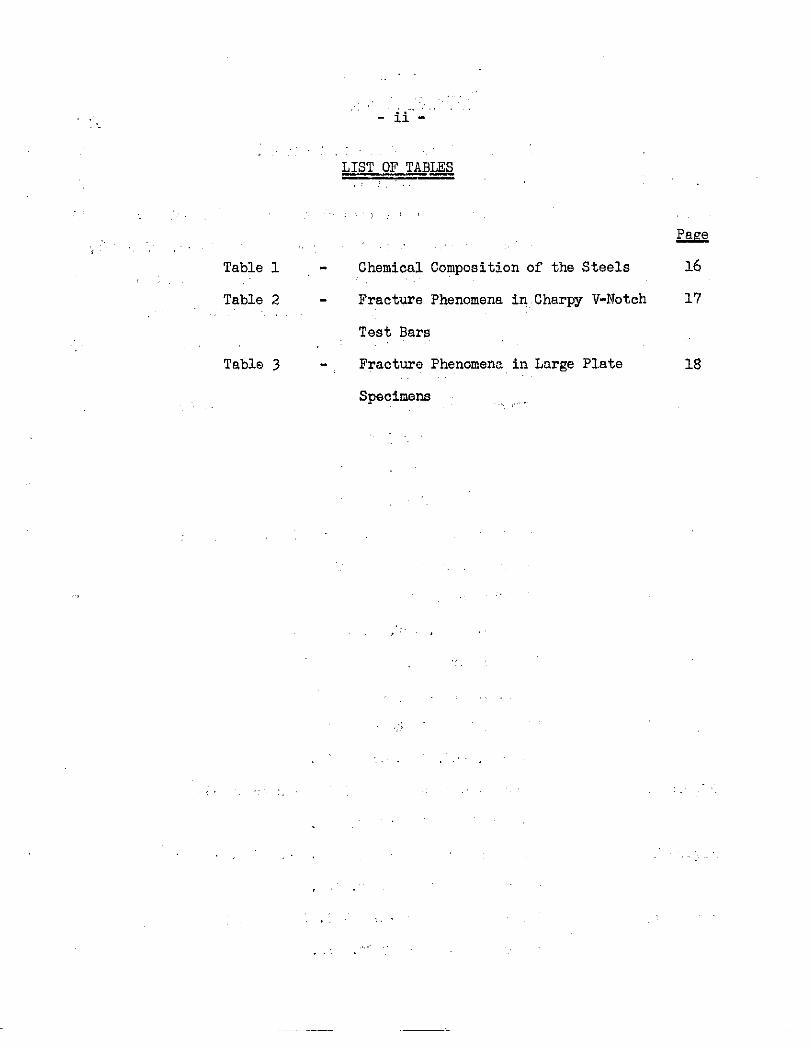
LIST OF TABLRS
LIST OF FIGURES
I - PUBIOSE
II - INTRODUCTION
A - ContinuityB - Theoryc - HistoricalD - FactsBearingon the ProblemE - Personnel
III - MATERIALS
IV - METHODSOF TEST
A - HardnessTestsB - MetallographicTestsC - X-Ray.halysis
v - RESULTSAlW3DISCUSSION
A- X-RayAnalysisB - HardnessGradientsof BrokenCharpyBarsc - HardnessGradf.entsof Bent CharpyBarsD- HardnessGradientsof LargeFracturedPlatesE - Metallography
W - CONCLUSIONS
i
ii
iii
1
1.
4
4
6
u
Vj

-i-
ARS1’RACT——
Straingradientsnormalto fracturesurfaceswere determined.Theee
fracturesurfaces were developedunderthe followingconditionsof test:
(1) V-notchCharpybarsbrokenby impactat variouslocationswithinthe
transitionzone,(2) V-notchCharpybrs bent,but not completelybroken,
by impactabcvethe transitiontemperature,(3) S1OW bendScbdt tYPebars
brokenbelowthe transitiontemperature,and (L) 72-inchwide,centernotdb
tensilespeoimensbrokenwith ductileand brittlebehavior.
The straingradientswere studiedby meansof hardnesstests,metallo-
graphicmethodsand X-rayanalysis.
It is concludedthat true cleavageseparationis not accompaniedby a
measurablestraingradientbut most ‘Ibrittle!!or Itcleavagettfractures,so
classifiedon the basisof grossappearance,containsomeareasseparatedby
a shearmechanism.
,’.’
Table1
Table2
Table3
,.!,
?:
..,.
;.-11-
LIST OF TABI@,. .,,.
.). ,
~
ChemicalCompositionof the Steels 16
FractqrePhenomenain.CharpyV-Notch 17
Test Bars
FracturePhenomenain LnrgePlate 18
Specimens
.,.+
,,, ,
,,.. .
,,
... ,

Figure 1
Figure:2
Figure 3
Figure ~
Figure 5
Figure 6
Figure 7
Figure 8
Figure 9
Figure10
Figure11
Figure 12
Figure13
Figure1/,
- iii -
LIST OF FIGUTUIS*
IdealizedFormsof StrainGradient. 19
X-rayPnttoins”‘SteelA. 20
The FractureMidwayThroughthe SpecimenSteelDr. 21
This is a ftil.yductilespecimen.(cf.Figures26 & 27).
The FractureMidwayThroughthe SpecimenSteelC.This
is a fullybrittlespecimen.
HardnessContours- Steelc.
energyabsorption3 ft. lbs.
HardnessGradient- SteelC.
energyabsorption3 ft. lbs.
HardnessContours- SteelE.
ene~gyab~orption7 ft. lbs.
HardnessGradient- SteelE.
energyabsorption7 ft. lbs.
(cf.Figures5 & 6),
Testedat -22°F;
Testedat -22°F;
Testedat 36°F;
Testedat 36%;
The Charecterof the Fractureat the Baeeof the
NOtchSteelE. (cf.Figures7 & 8).
The FractureNlidwayThroughthe Specimen
SteelIi. (cf.Figwes 7 & 8).
The Fractureat the Back of the Specimen
SteelE. (cf.Figuree7 & 8).
HardnessContours- SteelDr. Teetedat -39%;
energyabsorption10 ft. lbs.
HardnessGradient- SteelDr. Testedat -3903’;
energyabsorption10 ft. lbs.
HardnessContoure- SteelC. Teated at 50°F;
energyabsorption13 ft. lbs.
22
23
’24
25
26
27
28
29
30
31
32

Figure15
Figure16
Fignre17
Figure18
Figure19
Figure20
Figure21
Figure22
Figure23
Figure24
Figure25
,,, Figure26
Figure27
-iv-”
HardneesGradient- SteelC. Testedat 50%7;
energyabsorption13 ft. lbs.
HardnesaContours- SteelE. Teatedat 75°F;
energyabsorption16 ft. lb?.
Hardness‘Gr~&ient- SteelE. Testedat.75QF;
energyabsorption
HardnessContours
energyabsorption
HardnessGradient
energyabsorption
HardnessContouw
energyabico@ ‘.zn
HardnessGrddiont
energyabsimpti.on
HardnessContours
energyabsorption
HardnessGradient
energyabsorption
HardnessContours
energyabsorption
HardndssGradiQr,t
energyabsorption
Hardnese”Contours
energyabsorption
Hardn6ssGradient
energyabsorption
16 ft. Ibs .
- StselDr. Tested,at 16°F;
27.5ft. lbs.
- SteelDr. Testedat 16°F;
27.5ft. ibs.
- Steel I)?’.Testedat 64°F;
46.5ft. Ibe.
-“SteelDr. Teetedat 64%;
46’.5ft. lbs.
- SteelC. Te.atedat 113°F;
52ft.lbs.
- SteelCo Testedat 113°F;
52 ft. Ibs.
- SteelE. Testedat 17001’;
54 ft, lbs.
- SteelE. Testedat 170°F;
54 ft. lbs.
- SteelDr.,Testedat 1.26°F;
30.5ft. lbe.
-SteelDr. Testedat 126°F;
30.5ft. lbs,
Page
33
34
35
36
37
3$
39
40
41
42
43
44
45

.-v -
Figure28 “ H.ardness’CcnItours’- Steel.C. Testedat 212°F;.
energyab~orption+30ft. lbs.
~Figure29 HdrdfiessGradient.- Ste.elC. Testedat 212%;
energyabsorption80 ft. lbs.
“’Figure30 HardnessContours- SteelE, Teetedat 212°F;
energyabsorption7TIf%, lbs.
Figure31 HardnessGradient-SteelE. Teetedat 212°F; ‘
energyabsorption70 ft. lbs.
Figure32 HardneasContours- SteelC. Testedat 212°F;
angleof bend = 9°, no crackformed. Kinetic
Energyof Hammera 13 ft. lbs.
Figure33 HardnessContours- SteelC. Testedat 212°F,
angleof bend s 22°, emallcrackformed. “‘
KineticEnergy.of Hhmmers 34 ft. lbs.
‘Hartiess.Contours-’SteelC, Testedat 212°F,Figure3.!+
angleof bend : sgo, crackthrough1/3 of section.
KizleticEner~ of Hammer= 54 ft. lbs.,,
Figure35 Photographof PlateC-3.
Figure36 “‘
Figure37
:Figure38 ‘ ‘“’
Figure39
.~Figure40
Figure41
Figure42
Figure43
Line Drawing.ofFlatec-3,
HardnessContours- SpecimenNo. 1; PlateC-3.
HardneseContours- SpecimenJJo.2; PlateC-3.
HardnessContours- SpecimenNO. 3, PlateC-3.
HardneesContours- SpecimenNo. 4,”PlateC-3.
Photographof Plate22-IX. ,.
Line”Drawingof Plate22-IK.
Hardness..Contouis- SpecimenNo: 1; Plate22-I.K.
I-&&
46
47
@
49
50
51
52
53
‘5h
54
55
55
56
57
%
58
.—

-vi-
Figure.&l+ HardnessContours- SpecimenNo. 2, Plate22-M.
Figure.45 HardnessContours-SpecimenNo, 3, Plate22-IX.
Fi==e 46 HardnessContours-
Figure1+7 HardnessContours-
Figure48 Photographof Plate
Specimen
Specimen
N-l+A.
Figure49 Line Drawingof PlateN-l-A.
Figure50 HardneseContours- Specimen
Figure51 HardnessContours- Specimen
Figure52 HardnessContours- Specimen
Figure53 HsnxlneseContours- Spatimen
No. L, Plate22-lK.
No. 5, Plate22-lK,
II?O.1.,PlateN-1-A.
No. 2, PlateN-l-A.
No. 3, PlateIT-1-A.
NO. 4, PlateN-l-A.
Figure54 DeformetionTwinsin SteelC. NitalEtch x 6CXJ.
Figure55 StrainLinee in SteelDr. NitalEtchx 600
Fignre56 The Fracturefo~ SpecimenI!o.4 Plate22-IK
showingDeformationTwinsand Transitionfrom
Brittleto DuctileFailuro. NitalEtch x 500.
The Fracturefor SpecimenNo. 5 Plate.?2-IK
showingBritt3.e cracksof inter-endintra-granul.ar
Figure57
Figure58
Figure59
types. ]IitalEtch
AnotherRegionfor
Nitd Etch x 500.
x 500,
SpecimensNo. 5 Plate22-IK.
Characterof theFracturein SpecimenNo. 4
Plate22-lK. NitalEtch x 500.
&g
59
59
6C
60
61
62
62
63
63
64
65
66
67
68
69
7’0
—

I PWRPOSE
The purposeof this investigationwas to determinethe
the straingradient”at brittle“fracturesand at
II INTRODUCTION
J1-Continui@
characterietiesof
ductilefractures,
In the ProgressReport~of September15, 1946 “itwas indicatedthat a
reportwas beingpreparedrelatingto the etudyof etraingradientsas re-
vealedby hardneesmeasurementson impactbara fracturedat varicuslevaleof
energyabsorption.Th~e initialwork has been expandedto inolude(1) compar-
able testson lar’gefract~ed platee(2)X-Rayanalysesof strainat fractured
surfacesand (3) metallcgraphic
abovework is reportedhere.
B- ‘1’heory
examinationcf fracturedsectione. All of the
In attemptingto rationalizethe differe.nce,betweenbrittleand ductile
behftvicrin steel,,it has been s.uggeetedthat impcrtantinformationmightbe
gainedby an extensivestudycf straingradientsnormalto the fracturesur-
face. This suggestionis basedon twa facts:(1) a ductilefractme is
associatedwith a much higherenergyabsorptionthan a,brittlefractureand
, (2) the intensityand extentof plastic,strainare ind,icesof the energy
abeorpticn.Thus a studybasedon fact (2) couldconceivablyprovidedatato
explainfact (1),whichis the eseencecf the brittlechipplateprcblem.
Sinceit ie knownthat tbe energyabeorbedb>]pl~tic strainingincreaaes
witliboth the volumeof strainedmetaland tlieintensityof the strain,it
(1) - Numbersreferto itemsin Bibliography

-2-
,.,, .followsthat brittlebehavior,as contrastedwith ductilebehavior,must be
associatedwith”either(1)a smaller.voltie of strainedmetalor (2) lower
strainintensity.” F&ui% 1 schematicallyiQ@trates thesetwo possiblecliffer-
encesbetweenductileand brittlefractures.,.,.... ....,..,.,,
In Figure1(a),the strainintensityat the fracturesurf!aceis repre-
sentedas being constsiitfor all fractures,brittleand ductile. But the
ductile”fractureis representedby the gradualstraingradient,and will, there-
fore;be’associatedwith’a largevolumeof strainedmetaland..coneequentily
a largeefiergyabsorption;‘thebrittlefractureis representedby the steep
straingradientand will,therefore,be associatedwith’a smellvolumeof
strained‘metal“andconsequentlya smil~eoergyabsorption.:.ThusFigure1(a)
illustratesalternative(1)‘above.Alternative(2) is illustratedby Figurel(b).
Here,the strainintensityat the fracturesurfaoeis representedas beinghigh
for ductilefracturesand low for brittlefractures.Sinceenergyabsorption
increaseswith intensityof plasticetrain,it followsthat the fracture‘“”’
associatedwith high strainintensitywill absorba largesmovntof energyand
will be ductile,whilethe fractureassociatedwith the low strainintensity,:
will not absorbmuch energy,end will be brittle.,., ,,
(Fj.g,~e1 ~nd the,’subsequentdata of this reportassume;trainto be a,,,, .,linearfunctionof hardness. While this is not strictlytrue,it is a satis-
factoryapproximation,and ,straingradientsare representedin thisreportby,.
hardnessgradients),.,,.. ,.
c - Historical “ ., ,,...
‘Theextentof”plasticstrain“inthe iinpauttest hasbeen sttiie’dby
SauerwaldandWieland2,Moser3and others4)5> 6. Reviewsof the notch impact
,,,

-3-
test havebeen made by Fettweiss7$
and.MacGregorand Fisher . A studyof these
worksrevealsthe following:
(1) No extensiveanalysi.eof straining
of high sensitivity.Thus details
may have escapeddetection,
has been’undertaken
abo.~tthe vel~e of
(2) h’ocorrelatedanalysisof the volumeof strainedmetal
by method.s
st,rai.nedmetal
developedat
variauspointsin the transitionregionhas been publj.shed.This iS
an importantgap to be filled.
The presentwork is intendedto supplydata on both of thesepoints;
D - FactsBearinuon theProbl.6m—-. ——
Due“tothe characterof matter,any subs~ance;to a gre~teror Iess extent,,..
will functionas a “diffractiongratingfor X-rays. In ~~1 instancesof diffrac-,’
tion,the samefundamentalfactorsare operative,but optimumconditionsobtain
when the materialto be invcatig,clxxlhas a well developedspacelattice. Wlen
such is the case,and disregardingthe effectsof grainsize,well a:~i:edmaxima
in the diffractionspectraarisefor a giventype of spacelatticeat rtgor-
oualydefineddiffractionangles. Manyfactorscontributeto the finalappear-
anceof the individualspeetrallines,but thosefactorswhich alterthe appear-
ance of a givenlineas a functionof pinsticstrains.resomewhatlimited. This
wouldserveto decreasethe uncertaintyin the evaluationof a givenpattern
exceptthat$unfortunately,no one-to-onecorrespondencehoe everbeen ascer-
tainedas existingbetweenany of tho factorsmeasureda~d the degreeof plastic
strain. For instance,the obtainingof cliffused lineswhich is frequently
takenas indicatinga stateof plasticstrn.incan resultfrom chemicalcomposi-
tiongradients,elasticstraingradients,particleeizeand,certainlynot least
—.

important,externalgeometryof
of a fracturesurfacethislast
usuallycannotb,e
certainlypresent
be important.
E - Personnel
-4-
the cliffractj.ngsurface. In the exarnine.tion
factormay be a most importantfactor,which
modified. The effectsof
in a plasticallydeformed
elasticstraingradientsare most
metal,whileparticlesizemay well
The staffparticipatingin thiswork consistedof:
M, Gensemer,E. P. KlierJ. L. FisherF.C.WagnerJ.O.NlackM. A.BishopSelmaKrauseMina MoessenP.VonadaH. Colyer
TechnicalRepresentativeInvestigatorInvestigatorInvestigatorInvestigatorResearchAssistaz%DraftingTechnicalLaborTechnicalLaborTechnicalLabcr
TII MATERIALS
1$9Detailedinformationon the eteelsusedwill be foundi.nearlierreports .
Chemicalanalysesare containedin Table1,
Threesectioneof 72-inchwide plateewhich had beenbrokenby the center
9notchtensile testin the coureeof previousinvestigationsme shownby
Figures35, 41 and .+8. Specimensfrom theseplateswere usedfor hardness
contoursurveys.
IV METHODOF TEST—-—.
A-Hardness—-,——
StandardLH (longitudinalspecimenswith the notchperpendicularto tl?e
plate surface)V-notchCharpybarswere brokenat temperaturesselectedto
coverthe entiretransitionzone. Temperatures,energiesand fractwe

appearancesare listed
Afterfracturing
-5-
in TableII.
the barswere nickelplatedto preservethe fracture
surfaceand were sectionedon the centerplaneperpendicularto the notch.
The half specimenswere nextmountedin a plasticwhtihset,at room temperature,
and were polished. Finally,a regularpatternof indentationswas’made on the
polishedsurfaceusinga Vickersdiamondand a 1000 g. loadon a Tukonhard-
ness testingmachine. Preliminarytestshad shownthattheseconditionsof
testwouldeliminateany effectsof @e,inorientation,but wouldprecludean
appronch to the fracturecloserthan0.01 inohes. This degreeof sensitivity
is adequateto revealmacroetopicdetailof the straingradient. Preparation
qnd testingof specimensfrom the largefracturedplateswa~ done,in like
manner.
Thesehardnesedatawere plottedon a scaledlikeness
and linestonnectingpointsof equalhardnesswere drawn.
of the speciinens
Thie processgave
a hardnesscontourmap md, consequently,an approximatestraincOntO~ maP.
In“orderto permitrepieeentationof the n~rdness“gradientin a more easily
visualizedmanner,the linearhardnessgradientsat the base of the notchand
at a pointmidwaythroughthe fractufe,were determinedand plotted.
ThreeCharpyspecimensof steelC were testedin the conventionalmanner
exceptthat the hammer’was not raisedto its full height,ht rather“toa
heightinsufficientto causecompletefractureof the bars. The hammerre-
boundedafterstrikingthe bar, but was arrestedbeforeit couldstrikethe.,. . ,.
bar a eecond.time, Cond5.tionsof testwere ae follows:
,,.,;
,’
,.

-6-
Test,A
Temperature‘F 212
K, E. of Hammer 13
BendAnglo
Crack
These specimens
B-Metallom?aDhv
9°
None
were eectioned,mounted,
Test B’
212
34
22°
VeryShallow
polishedand teeted as
TestC
212
54
38°
113 throughBar
describedabove.
Ilicrosectionsweremade of all specimens,and photomicrographsof the impact
specimenewere takenat the
Microstructumlevidenceof
was observedand recorded.
notch,midwaythroughthe bar and at the back side.
Neunmnr,Bands~ strainlinesand graindeformation
C-X-RayAnaIvsis-——
Specimensof steelO
face and ductile’fraoture
representingthe virginmetal,a brittlefracturesur-
eurfaceswere used. In orderto insurea cleanand
completebreakat tke fracturestifrices,the Schrwdttypebar was ueed and wae
biokenby the elow’bend technique..4Sachs type camerawith both cassetteand,,, .
specimenstaticnuy was ‘used.Exposureswere madewith K 0< radiation.
V - RESULTSAND DISCUSSION
A-X -RqvTests
The X-raydata are presentedin F igure2. Pattern(a) is for the virgin
metal. Tbe pointof interestis the resolveddoubletleadingto two lineson
the pattern(<~ and< ~). Thoselineeare typicaland are used as reference
lines. Patterns(b),(c), (d),and (e)were tn.kenon duc”~ilefract~lres~f aces.
From the lack
existsat the
of resolutionof the doubletit may be etatedthatextensivestrain
fracturesurface. Fincllyin pmttern(f),takenOn a brittle

fracturesurface,
the strain}if it
the doubletis
existsfor the
-’7-
resolvsdas in pattsrn(a). This meansthat..
brittlefra.ctu.re,was insufficientto be picked
Up by.thisX-my diffrm.tiontechnique.Sinceit is estimatedtho.tthe X-ray
procedureused will reveala straingradientof .0001inchthicknees,it ie
indicatedthat a straingradient,if it existsadjscentto the brittlefrr.cture
surface,must be no thickertkn 0.0001inch. A gra.dient of this exteutcould,
underno circwsstanccw,leadto high energyabsorptionin its development.From
thisit followsthatfor practicalpurposes~ the straingradientconstruction
presentedin Figurelb conformswitlitileexperimentalresults.
Additionalinformationin termsof metnll.ographicdatapertainto th;.spoint.
Thus,in Figure 3) the frocturesurface is typicalof a duchilefailure. The
metallcgraphicstructureshowsa highlytornand deformedzonee.tthe fracture
edge. This zoneo.ppearsto be of the orderof .01 inch thick. This region
rapidlypassesintoa zoneof much lowerplaSticstrain~rIzom, howeverj in
whichplasticstrainis stillappreciable,cm indicatedby the distortedgrains.
-In Figure4 the fracturepresentedis to.brittlefracture. Thereis nO evi.donce”
of plasticstrainaccompanyingthis frc.cture.The metellographicdata~ there-
fore,me in full agreementwith the X-raydata,for the considerationof the
‘ideal)!brittleand ductiletypoeof failure. Add;.tionaldata concerningthe’
metallographyof mlmt mightbe consideredintermediatetypesof failureare
presentedin subsequentsections.
The X-rciyand metallogra.phicdata
aceeptanoe.ofthe straingradienttype
the straingradienttypepresentedin
tionsat the fracturesurface.
whichhc.ve“beenprese~itedargueagainst
prbsentedin Figurela. By elimination
Figurelb appearsto destribethe condi-

-8-
B4H~~ne~~ Gradients,0f B~OkenCharpY Barg
Hardnessgradientdataare presentedin Figures5 to 8 .snd12 to 34, in
the formsof contourmaps and lineargradientsat the notchand at the ceuter
of the Charpyspecimens.Theabdatawill be consideredin groupsbadedon sim-
ilarityof enerf$absorptionand posi“tionin’the iraneitionzone.
Group1 - Low EnergyAbsorption,(<7 ft. Ibs.) Figures5,6,7,and 8. The
,speoimenof steelC ( Figures5 and 6) with an energyabsorptionof 3 ft. 10S.
would be considered‘)100~granular!tby conventionalueage. The hardnessc~iltO~
indicatesvery slightetrainsat the notchand underthe tup, but the crack
itselfwas not accompaniedby strainwhichwas discernibleby the hardnessmeas-
uringtechniqueused. Thesesameremarkeapplyto the specimenof eteelE
(Figures7“and 8), with the exceptionsthatthie fracture.showd slightlymore
sheartinderthe tup and greaterstrainat this location. Photomicrographsof
this specimen( Figures9,‘10,..and I.1)are~in agreementwith the hardnesadata.
It is,evidehtthat the crackin.thisspecimenwas compl..etedbeforethe major
~part of the straining”occurred. Thisfollowsfrom the fact that it wouldnot be
@e&ible to’sti%ifi‘an.untrackedspecimenat the tup withoutcaueinga ccurespond-
ing &trainat the motch. Hence,most of “theetrain at the t~ must have reeulted
from bendingof the”epecimenaf$er completionof the brittleportionof the crack*
Group”2- MediumLow”EnergyAbsorption(10-16ft. lbs.) Figtime.512-17..The
hardnesscontoursof khisgroupare similarto thossof group1 with the excep-
tion the strainat the notchand the tup is greater,and consequentlythe length
of the brittlecrackthroughunstraitwdmetalis shorter, The same.analysisof
strainingpriorto; and after,formationof the brittlecrackapplies. Notice
thatthe brittleportionof the crackis stillnot accompanied..by a macroscopic
straingradient.

-9-
Group 3 - [email protected].(27.5- 54.0ft. lbs.) Figures
18-25. The hardnesscontiov.rsof this groupare similarto thoseof groups1
and 2 with the cxoeptio~lsthat the zofleeof strainat the notchand th6 tup
are stillgreaterand are extendedsuffici.ently,at 45° to the specimenaxis,
to contacteachotherbeneaththe crack.(e.g.Figurelb’). Theresti~~exist
regionsof brittlefracture,however,showingn,omacroscopicstraingradient,
with the poesibleexceptionsof curvesE in Figures16 and 23. Theseslight
etraingradientslikelyresultfrom the appreciablebondingwhichoccurredprior
to the formationof the crackratherthanfrom a mechanismaccompqningthe
brittlecrack. ‘Notethe markedrise of the B curves,whichobviouslyreflects
the extensionof the strainedzonesat the notchand tup.
Group4 - HighEnergyAbsorption(>’70ft. ibs.) Figures26-31. These
fractureswere fullyductiluonos. The hardnesscontoursshowthat the region
of no strainat the centerof the barshas vanished. However,tineintensityof
the strainat the centm of the bars ie stillmuch lowerthem it is near the,’
notchand tup.
Thesestraingradientstudiesof brokenChe.rpybarslead to threeobserva-
tions:
a- A ductilecrackin a Charpybar is not accompaniedby a distinctfva
and uniformmacrostopicstraingradient,for if it werejtheA and B curves of
the totallyductilefractureswouldbe alike.
b - A brittlecrackin a Charpybar can be propagated
free,or slightlystrainedmaterial~ withoutimpositionof
gradient.
througheitherstrain-”
0. macrostopicstrain
c - The macrosco~picstraingradientsof a brokenCharpybar largelyreflects
the strainresultingfrom bendingactionsratherthanany crackpropagation
phenomena.

.
-1o-
,C-Hardness”Contotisof BentCharm Bars
The hardnesscontoursof the threeCharpyb~rswhichwere struckby a
Che.rpyhcmunorpos.+essingenergyinsufficientto causecompletefractureare
shown in Figures32, 33, and sl~,
Figure32 illustrates‘the‘distributionof the etrainpriorto crackforma-
tionfor conditionsof testunderwhichductilefracturewouldoccurif energy
sufficicntti effect’fracturewere availnble. Noticethe steepstraingradient
renderthe “notchand, to a les’ecr degree,at the tup,and the strainfreemetcl
near‘tothe neutralaxis.
Figure33 cliff ers fromFigure3’2in degreeonlywith the exceptionthata
shallowductilecrackextendsfrom the notch.
In FigureZ; the betidingactionhas proceededsufficientlyto causestrain
at the centerof the bar,and the ductilecrackis extendedfurtherintothe
materialstrainedby”bending. The straindistributionand intensityresemble
thoseof Figure2S~ whichrepresentsthe snmosteeltestedat the same temperat-
ure but with energywhichwas sufficitmtto causetotalfracture.
,,
D - HardnessGrc.dicntsin LargeFracturedPlates.—.
It is evident,from resultspresmted ‘above,thattilestraingradientsin
brokenCharpybars are largdlyreflectionsof the amountof bendingpriorand
subsequentto the formationof thd crack. Consequently,it was realizedearly
in the couzseof this investigationthatfractureswhichhad occurredundsrthe
actionof tensileforcesonly should.be includedin the straingradientstudies.
For thisreason,specimensfrom T2-i.nchwide plates~ whichhad been fractured
in the centernotch
PlateC-3 will
tensiletest,
be considered
were examined.
first. From the chevronmarks (Figure35)

-11-
it is evidentth?.tthisplatefailedwith a !Ibrittlet!crackterminatingat the
notch. Figure36 indicatesorient[!.tionsend locstionsof the hardnesssurvey
specimens.Figuree37-40show the hardnesscentaurs,fromwhichtwo significe.nt
o’csorvationscan be made:
(1) Some portionsof this s~ittl,esCr:,Ckare not accompaniedby o dis-
cerniblemacroscopicstraingradient,i.e.~ the brisehardnessof the plateex-
tendsunchangedto the cracksurface.
(2)Some portionsof this ‘tbrittl.etlcrackire accompaniedby fairlysteep
and shallowstraingradient+,whichcan occurin the centerof the pi.fite(e.g.
Figure351)but lwhichare especiallymarkedat the plateemface (e.g.Figure40).
Theeoobservedfactscompelthe conclusionthat thoseLocationson the
crackwhich are urmccompaniedby a etraingradientwere cracksindeedpriorto
the separationof the materialat thoselocationson the cre.ckwhich are accom-
paniedby a straingradient. The most obviousof the possibleexplanationsfor
this markedvariationin the straingradientsat di.ffercntlocationson the
same IIbrittlellcrackis that the reducedconstraintresultir,gfrom the growth
of the crackallowedappreciableplasticstrs.inat the locationswhichwere
lastto separate. But in amy event?thesespecimensindicatethatc.crack,
whichwouldbe classifiedas !Jbrittlo!]by conventionalcriteria,may or may not
be accompaniedby a macrostopicstraingradient.
Plate22-lKie shownin lin~drawingby Figure42. From its photograph,
Figure41$ it is evidentthat the crackwae !~ductile!ifrom the notchto the
locationof specimenNo. 4$ thence‘}brittle!!to the plcteedge. With the addi-
tionalobservationthatthe ductileportionsof this crackshow the expected
straingradient,(FQurcs 43-47)the resmrkspertainingto platepreviously
discussedapply. ,. ,,
,.
~.

Plate N-1-A is shownin line
Figure48, it is evidentthatthe
-12-
drawingby Figure48. From its photograph,
crackoriginatedat the notchnnd extended
in the 1!ductiletlmode for approximately1/2 inchbeforethangingto the !lbrittlell
mode. It shouldbe noted9that thisplatewas unusualin that it absorbed
approximately1/3 of the maximumenergyobservedfor a totally‘1ductilet!speci-
men of the s?mematerial. The straingradientsof thosespecimensnear the
notch,Figures50, 51, and 52, closelyresemblefindingsfrOm the PrevioustwO
plates. Figure 53, however,which represents‘Ibrittle!!behavior,differs
markedlyfrom the otherSbrittlo!!contoursin its demonstrationof definiteand
uniformlydevelopodmacrostopicstraingradient. In thisrespect,Figure53 is
not unlikepreviouslydiscussedcontourmopswhich represent‘tductile!’behavior
(cf.Figure43), with the exceptionthat the gradientslopedoes not sharply
incrcceein steopnessnear to the fracture. It is suggeetedthat the “brittle
gradient’]of Figure53 mightbe relatedto the unusuo.llyhigh energy?.bscrption,
in th~t it couldbe reflectinggeneralstrainingin a zonebetweenthe notch,.
and the plateedge rather“thann strainincidentc.1to, or necessaryfor, propa-
gationof the crack,
E - liietdlograph~
Results.ofmital.lographicexaminationare“presentedin Tables2 and 3,
and in Figures3, 9 to llj and 54 to 59.
.Inthe tables,frccturetypesaro listedas ‘tbrittle,‘t‘tductile,” and
‘tbrittle-ductile,’)The lastmentioneddesignationindicatesuncertaintyas to
the typeof behavior. It shouldbe emphasizedthat theseclassificationare
based.onmetallo’grmphicdata only,
Figures9, 10, and 11, respectively,
sdctionswhich intersectthe crackat the
illustratethe microstructurosof
baseof thenotch,midwaythroughthe
1

-13-
bar and at the backof the bar,of a !Jbrittle!!specimen($teel.E, 36°E). The
straingradientsof thisspecimenare representedby Figureo7 and 8. It can
be seenthat the hardnessdata and m.icrostructui%sme in rwyeenent,with the
exceptionthatmicrostruct,lme(Figure9) showsevidenceof considerableplastic
strainin a very restrictedzoneat the base of the notch,whiohstrainis not
evidentin the hardneeaconto~ (Figure7). This ~!dis.c.greomentt!unqueetionc.bl.y
reflectsthe greatersensitivityof metallographicexamination,as comparedwith
the hardnesstests,and stronglysuggeststhat the strningradientsat ductile
fractmes are actunllymuch steeperand reachmuch higherstrqinvaluesvery,, ,,
necr (< 0.01”)to the cracksurfacethan is indicatedby the M.rdneescontours.
Figure10 clearlydemonstratesthe total.lack of any metnl.lographicme.nifesta-
tionsof strainat s.cleancleavageseparation.,.
Figures5/,and 55, respectivelyillustratedeformationtwinsand strain
lines,not necessrn’ilytypical,ocmrring in brokenCharpyb~rs.
Figure56 representsthe locationin plate,22-l-Kat whichthe cre,clr,,
chnngodfrom the ‘!ductil.elrto thG ‘Ibrittle!tmode. iiotetho typicalevidence,,, .,,-.. .,,..,’
of an appreciablestraingradientadjocentto the ductilepart and the clean,
etrain-freecleavageadjscentto the brittlepartof the crack.
Figure57 representsa !Ibrittlel)locationof the cremkin plate22-1-K.
The previouslymentionedcharacteristicsof Q cleavagefracturdare illustrated.
Note also the typicaltrans-crystallinepath,which is interruptedby a very
shortinter-crystallineseparationat the pecrlitegrainnear crackmidpoint.
Figure58 illustratesthe abovementionedcharacteristicof a cleavage
crackand in addition,rcve:llsinterestingbehaviorof the crackin the ferritd
grainnear its midpoint. Noticehow the crcckbranchwas rnuwatedwithinthe
ferrite.grain.
—

-14-
“Figure59 representsa cleavagecrack. Of interest.isthe deformation
of the ferritef~agmen@ whichevidentlysuf~eredConsiderablestrain,
althoughttiecraokcausedno discerniblestrainin the main body of the ferrite
or pearli$egraine. ,,
,,
VI CONCLUSIONS,, ,,..,,
1- ‘“”;The etraingradienta; some’~ocationson any Sbrittlell&ra”ck,if it
!,~,’;. ,..,. existsindeed,ie so restricted’aS to depth’that it is not detecthble”by
,,X-rayor metallographictests.
:<
,, ; ,; ,,.., ,.:
2 -“’ The straingradientsat somelocationson most’‘brittle’$crackbis,.;,,; .;
not characteristicallydifferentfrom the straingradients0$”a“1$diet’~lei!,. . ,, ,,,,,1,,’‘.+i! ., >. i,:..,.:
crack.
3- Fractureswhichwouldbe classifiedas “b~itt,le”by convehtf.onalusage,, ,’ ,. .’,
e.g.,by,CYOSSappearance,generallydisplay”’both Of”the abovetwo typesof*;:r ‘,,:.:~.!. .,.1 : .:.,:
straingradients.,: ,!.’.”
4- ““ Figure1(b) schematicallyrepresentsthe differencebetweensepara-,,:~~
tionby shearand separationby cleavagewithrespectto etraingradients,,,, . ., .,,,, ,,, .
exceptthatthe cross-hatchedareashouldbe isiieaetiably””amal~.,,.,,...,;.,..:.:
,..’..: !.”
,. (
,., .
,,, ...
,,.

-15-
REFERENCES ““’”“
1.
2.
3*
l+.
5.
6.
7.
8.
ProgressReport- ResearchProjectSR-96,SerialNo. SSC-9,Contract
NObs-31217datedMarch19, 1947.
F. Sauerwaldand H. Yieland: Z, Metallk.~ (1925)‘p.358/63and 392/9;
St. und Eisen46 (1926)p. 5.46.
M. Moser:KruppesheMonatsh.2 (1921)p. 225/40. St. und EisenQ (1922)
p. 90/7;Z. V. D. 1. ~ (1922)p, 43.
R. Hinzmann: Dissertation.Techn.Hochsch.Berlin,1925.
F. Sch~e: Materialpr~. Anst. a,d. Eidg.Techn.HochschuleZ}rich1913,
Vol.10a.p. 1/16;St. und Eisen~ (1911+)p. 1266,
F. Sch’~eand E. Brunner: Intern.Verb.KopenhagenerKongress1909 III,2,p
1/6;St. und Eisen~ (1909)p. 1453.
F. Fettweiss: Archivf[r Eisenh\ttenwesenApril 1929,Vol.10, p. 660.
C. W, MacGregorand J, C. Fishert Jrnl...AppliedMechanicsQ ~flarch(1944)
p. A28/A34.
9. FinalReport- ResearchProjectSR-92}SerialNo.
‘datedJanuary1947.
10. FinalReport- ResearchProjectSR-93,SerialNo.
datedJune 1947.
SSS-8,Contractl!Obs-31.222,
SSC-1.0,Contractl!Obs-31224,
11. C, S. Barrett: Structureof Metalep. 305. LlcGraw-HillBook Company,
New York (1943).

-16 - L
. .
TABLE I. . .
ChemicalCompositionsof the Steels
,.., .’ ””,
m THERMALTR.EATMEii’f~ % &“”’m.,... ,,,,:.,: .,.
A As-rolled 0.26 0.50. .,0.02:
c As-rolled o.2~; .! 0..4$, :.:Q,Q2.:“
Dr As-rolled 0.22 0.55 0.,16,,...,,.’
E As-rolled 0.20 0.33 0.15
c-3-A Same as C above,,.,,
22-’lK Same as Ilrabove
N-l-A As-rolled.,
0.17 0.53 3“39

TAB:EII
Spec.
KRI-5KRA-1KRG-4KFrF-6
I-28I-51-21-19
31W-3RRB-1RRC-3R31-1
Steel
DrDrJrDr
Gccc
~EEE
TestTerm,,‘F
-40-91852
-30254598
22477
100
FracturePhenomenain CharpyV-l~otchTest Ears ‘
FractureTypeand Lo6ation ‘ DeformationStiuctureand Location
E.A~l# “ ‘Notch Center ~~“ Back Iiotch Center Back. .
—- — —.-..
m ‘“ d, “. B B-D lT.13.3 17=3. s=I1.2’?.5 ~z B D S.L04 N.B. S.L.46.5 D B D S.L. y.2.
80.5 DS.L..
D D S.L. ~-.,.A. S.L.
B B B N.ti. ~,;:BO N.13.3; D B D S.L. “~~.B.(2) S.LC :
D 3 D S.L. ““’B.,,. S.L. tz D B-D D s.Lo S.L., S,L. F<
,B B B-D ~:..B. 1~.B. “i~.B. & ‘S.L.
1: B-D B B S&. ~:e~. N<.B,5L B B-J B-D s.I,. N.B. s.,L.70 D D
1 - B = Brittle2 - D :=Ductile
3- N.B.= NeumannBands4 - S.L. z StrainLines
.
I) S.L. S.L. S*L.
(deformationtwins) ::...
.. .. .

TABLE 111—.
FractureF%enornenain LargePlateSpecimens
~m(lfNIA(2)rIA(3)NIA(4)
I C:3(1)C-3(Z)c-3.(3)C-3(4)
22-lK(l)
!
22-M(2)22-lK(3)22-lK(4)22-IK(5)
101to
104
FractureTypa& Location6 DeformationStructure& Location.1. 2. 3 1. 2.- 3.
~1 D D.,D D D ~L.3 CL, ~L .. ..
D!2. B
D — — —o B — — —
B B B-D S.il.’—B B B }!.B.fi S.L.(r) N.B.—B B B-D ROB. N.BO & S.L.(r)~.B B B a.L. N.E. S.L.
D DD B-DB-D BB B
DDB-DBB
~. ~ S.L.~..”.,’=“.L. S.L.S.L. 4S.L.(r) Cars— —
1 -D= Ductile2 -B= Brittle3 - S.L. = StrainLines4.- SOL...= StrainL@es highlyrestricted5.- N.B. = Neumannbands (deformationtwins6 - Specimennumberand locationmay be takenfrom appropriate~
line drawing(figures35,42, ad 49). Locations 1, 2, and3 are left,centerand rightportionsof.“transversespecimenslookingin directionof crackpropagation;they denoteleft,centerand right portionsof longitudinalspecimenswith thenotchto the left.
S.L.S.L.—
1:-J0)
I

FIG. I IDEALIZED FORMS OF STRAIN GRADIENT
1_______——‘ii’\\\\ \!%\ ‘\\\ \ .\\\ \\ -.—.>. —————’-— ——————-
BASE H1
(b)
‘\ ---_____ __
\\
( “%\&\\\?.. ::_’ ______
~\
iD–N Essi
\ I
l-—————x—————L------DISTANCE FROM CRACK DISTANCE FROM CRACK

20
Fig. 2 - X-ray Patterns Steel A

21
Fig. 3 The Fracture Midwey Through the Specimen Steel Dr.Thi6 18 a fully ductile specimen. (Cf. Fig. 26 C?27)Nital Etch x 600.

.22
Fig. 4 - The Fracture Midway Through the Spec~men Steel C.This is a fully brittle specimen. (Cf. Fig. 5 & 6)Nital Etch x 600.

FIG. S
DPH CONTOURS STEEL C
v- NoTcH SpEaktEN
A B TESTED AT -22°F
ENERGY ABSORPTION 3 FT.-LBS.
,/15~
/20+
/20 *
0.0 0.3 0.4
WIDTH-INCHES

24
22a
20C
18Ca<~
: 16C
Tr&n
I4C
12C
I 0(
4FIG. 6
HARDNESS GRADl ENT STEEL C
V- NOTCH SPECIMEN
TESTED AT ’22 ‘F -
ENERGY ABSORPTION 3 FT -LB
CURVE A
●
0.1
—
0.2
DEPTH BELOW FRACTURE - INCHES

25
wJmw1-(J3
k
w
m .—-..>— .—.
<
o‘+
obT--

26
220
200
180
nuo-J~ 160*Tza~ 140
120
I 00
FIG. 8
+ARDNESS GRADIENT STEEL E
V- NOTCH SPECIMEN _
TESTED AT 36 *F
ENERGY ABSORPTION 7 FT. - LBS.
\CURVE B .
0. I 0.2
DEPTH BELOW FRACTURE - INCHES

27
Fig.
‘,
9- The Character of the Frecture at the Base of theNotch Steel E, (Cf. Fig. 7 & 8). Nital Etch X 600.

Fig, 10 - The Fracture Miduay Through the !3peclmen Steel E.(Cf. Fig. 7 & 8). Nital Etch x 600.

29 “
Fig. 11 - The Fracture at the back of the Specimen Steel E.(Of. Fig. 7&8). Nital Etch x600.

FIG. [ 2
DPH CONTOURS STEEL or
V-NOTCH SPECIMEN
TESTED AT -39 OF
‘)0
ENERGY ABSORPTION I’D FT.-LBS.
17 A-, *A I I - \
1, II0, I 0,2
\
I0.3
WIDTH-INCHES

31
E00
\\ #
120
100
DEPTF
FIG. [3
HARDNESS GRADIENT STEEL D r
V-NOTCH SPECI MEN _.
TESTED AT ’39 “F
ENERGY ABSORPTION 10 FT. -LBS.
CURVE A I I
2+5---F0.1 0-2
BELOW FRACTURE - INCHES

FIG. I 4
DPH cONTOURS STEEL C
V-NOTCH 9PECI MEN
TESTED AT 50 “F
A B ENERGY ABSORPTION 13 FT. -LBS.
,176 .132,S[60 1s0
./s5 )=130 “/.26.5
r
‘Y
/90 ,/44,5 .1/4 170;llo
I
)
(
1,/90 *117
~~
I I/30? .1 3
>
.115,5@
,133.5
k
/30 / o
\fn ‘7°
~ 30 >; <y
!/%3.5
!/25
I
/ / [’2”5I
o.I 0,2
WIDTH-INCHES
I
I0.3
uto

33
240FIG. t 5
HARDNESS GRADlENT STEEL C
220 ~V ‘NOTCH SPECIMEN
TESTED AT 500 F
ENERGY ABSORPTION 13 FT -LBS.
200
n
~ 180
0<iX 160&o CURVE A
I40
\‘Q
120 ~>L .g’
o\CURvE 8
I 000.1 0.2
DEPTH BELOW FRACTURE - INCH ES

u-i
wmJ
(nwsv
*5-.01
s1-0
3
<

35
220
200
180
160
140
120
100
1
FIG. 17
IARDNESS GRADIENT STEEL E
V-NOTCH SPECIMEN –
TESTED AT 75 “F
:NERGY ABSORPTION 16 FT-LB S.
CURVE A
0.1 0.2
DEPTH BELOW FRACTURE - INCHES

FIG. 18
DPH CONTOURS STEEL Dr
WIDTH -lNCHEs

37
FIG. 19
HARDNESS GRADlENT STEEL DI
V-NOTCH SPECI MEN
TESTED AT 16 ‘F
ENERGY ABSORPTION 275 FT.- LBS
9
0
/
./z
/00
/ 0“-c-~” CUR VE B
0-
0.1 0.2
DEPTH BELOW FRACTURE -1 NCH ES

38

39
k-lFIG. 21
@ HARDNESS GRADlENT STEEL Dr
220V-NOTCH SPECIMEN
TESTED AT 64*F
ENERGY ABSORPTION 46.5 FT-LBS
180 ,
160
140 -
00~%= >0
0
120
I 00
b
CURVE A
● *
/“ \“
0/ ‘“*/ CURVE B
//
&
I I
0.1 0.2
DEPTH BELOW FRACTURE - INCHES

FIG. 22
DPH CONTOURS STEEL C
V-NOTCH SPECI MEN
A BTESTED AT I I 3 ‘F
ENERGY ABSORPTION 52 FT.-LBS.
WI DTH-lNCHEs

240
220
200
n
~ 180J
ox
i160
:n
14C
I 2C
10(
●
k●
9
FIG. 23
HARDNESS GRADIENT STEEL C
V -NOTCH SPECIMEN
TESTED AT I13°F
ENERGY ABSORPTION 52 FT.-LBS.
CURVE A
\
●
0°
/ CURVE B/
?’ ~
o. I 0.2
DEPTH BELOW FRACTURE - INCHES

FIG. 24
D PH CONTOUR S STEEL E
V-NOTCH SPECIMEN
TESTED AT 170 “F
~ B ENERGY ABSORPTION 54 FT.-LBS.
K/+o-
,(0>~w?fwqy
I I I I0.I 0!2 0.3
WIDTH-INCHES

43
FIG. 25
HARDNESS GRADl ENT sTEEL E
v -NOTCH SPECIMEN -
TESTED AT 170 ‘F
ENERGY ABSORPTION 54 FT. -I-B:-.. —..
\
●
●
m 1
/ “ CURVE B ‘\0/A ●
M’ 0
0.1 0.2
DEPTH BELOW FRACTURE -INCHES

,.’ L+

45
220<
200 b
CURVE A●
./A\
4I 80 K
n
q l!” C:RVE\oh
~ 160 \“
ix0.n
140FIG. 27
HARDNESS GRADlENT STEEL Df
12 0V-NOTCH SPECIMEN
TESTED AT 126 ‘F
ENERGY ABSORPTION 80.5 FT-LB s.
I100
I
0.1 0.2
DEPTH BELOW FRACTURE - INCHES

Mi
Uim
aml
dG
L
zIll
‘T––=––
-:’
—
V)w
N-.c)
—
-6

240FIG. 29
HARDNESS GRADlENT STEEL C
V-NOTCH SPECI MEN -220
TESTED AT 212 “F
● ENE;GY ABSORPTION 80 FT. - LBS.
200●
CURVE A
n●
●
u o
q 180/
/ ‘o
0 0 oOgSt
o CURVE B--.+ _ .- /~
i 0
X 16 0mn
140
120
loo~ Io. I 0.2
DEPTH BELOW FRACTURE -INCHES


49
240FIG. 31
HARDNESS GRADIENT STEEL E●
220 V-NOTCH SPECIMEN –
TESTED AT 212 “F
ENERGY ABSORPTION 70 FT-LBS
200CURVE A
og 180
0~-.CURVE B
o 0x
i —~~ 160 .s
● O’\
a●
●
140
120
1000. I 0.2
DEPTH BELOW FRACTURE - INCHES

1130- 0
0 \,,
!30- ! 120-
/
120 +/’ 7
~)@ O1.l.oW<p:i.LL,
‘$2 jJ~~;-
a
120-.J
u!0
D
!20- 120-
! 20 120 ,*
10 IM 1s0
([
o ‘7” ‘e” ‘ ’40 ’30Iao
I 70
0!0SCALE IN INCJWS
& CA

51
-a
0-(N‘N
II
Ic-lco
0-0

52
/‘\ ,
/’” ..\-’ . ......_.._J\~‘) ~-–--””“-”----- “–” ““””\~_
\ ,’”(“-”””””5”””\ \

53
&.,4
!+

PLATE C-3
.0..,,0. OF SP, clklc.s
__ c: ~___—.– .—. ––.. .- ,.,., ”., ——- .— — -
L---. --—
.0., A ,.,’ ,,2.,
Fig.36 - Line Drawingof PlateC-3.
.,, . . CONTOURS
I KG. LOAD
,.,,, c ,*PEC .0
Fig.37 - HardnessContours- SpeciimnNo. 1, PlateG3.

55
D P H ,..,0”.s
KG LOAD
,,
T:,..
,6. , ,,...0-
!,0,,,. ‘m’
%%. %
,6, ,,,. , ,,,.
,6. $ !60 ,,0.E4.
o ‘“”,,0.
Fig.38- HardnessContoursSpecimenNo. 2, PlateC-3
o P. CONTOURS
, .’ mm
,,.,, .3
,,,.. .0.3
;. 0’6 o.i& 02
,CALL .1. l...~,
Fig.39 - HardnessContoureSpecimenNo. 3, PlateC-3

56
., P CONTOURS
. . LOA,
., AT, .3sm. .04
Fig./+0- HardnessContoursSpecimenNo. 4, PlateC-3


58
-— c , —WCTILC+ --- - a.’,,,, FRACTURE ‘—
r’y’-- ‘w X —.0 % —-
Fig. L@ -
o P,H. CJXTO”P5, w. mm
PM,, 22-,.
.,,, WI
Fig. Id - HardnessContoursSpecimenNo. 1, Plate22-lK.

59
Fig.l+k- HardnessContoursSpecimenNo. 2, Plate22-lK.
Fig. 45 - Hardness ContoursSpecimenNo.3, Plate22-lK.

60
0.,?. Cn.m”.,
( KG mmKATE ,2.,.
s,,. m.
Fig . k6 - Hardnesm GontOuraSpecimenHo. l+,Plate22-lK.
OP. .0.,0 ”.,
, .’. ,0..
,,.,. 22,.
wig. 1+7- Herdness ContoursspecimenNo. 5, Plate22-lK.

61

62
m,,, .! ALOCATION OF SPECIMENS
k. —..,. ...+.. --—- FR,’T..E —— .—.
p. ..,%... .L
I
‘~..—.%-~,~? IJ~i m u “f
NOT. : A ,,EC. ,,3,4,
, ,,s., ,
I
II
—3. 7[, ———..
{
c H ,RACT”61 IS OF WCTIU NATURE FOR APPROXIMATELY @,,,ROu cur. WANCE Calrm.c.
Fig. L9 - Line Drawingof PlateN-1-A.
0? H CONTOURSKG m.,
m.,, N,.
0’0 0:2 0:4 & ..i5CALE !N INCHES
Fig. 50 - HardnessContoursSpecimenNo. 1, PlateN-l-A

63
w“ CONTOURS
, . . LOAD
Fig. 51 - HardnessContoursSpecimenNo. 2, Plate N-1-A
, ,. ‘0.,0.,,
. . LOA,
,,.,, ., A
s-c .0 3
Fig. 52 - HardnessContoursSpecimenNo. 3, PlateN-l-A

,,..
Fig. 53 - HardnessCOntOUrSSpecimenNO. 4, Pkte N-1-A

65
Fig: 54 - Deformation TWiIIB in Steel C. IiitalEtch x 600.

66
Fi~, 55 - Strain Lines in Steel Dr. Nital Etch x 600.

67
Fig. 56 - The Fracture for Specimen No. 4 Plate 22-lK showing DeformationTwine and Transition from Brittle to Ductile Failure. IUtal Etchx 500

Fig. 57 - The Fracture for Specimen No. 5 Plate 2>1K ehowing Brittle Crack%of inter-and intra-granular types. Nital Etch x 500

69
Fig. 58 - Another Region for SPeoimens No. 5 plate 2~lK.Nital Etch x 500

70
Fig. 59 - Character of the Fracture in Specimen No. 4Plate 22-M. Nitel Etch x 500.