a ship-to-ship automatic docking system for ocean cargo ...cmss.kaist.ac.kr/cmss/papers/2014 a...
TRANSCRIPT
ORIGINAL ARTICLE
A ship-to-ship automatic docking system for ocean cargo transfer
Yong Yook Kim • Kook-Jin Choi • Hyun Chung •
Soonhung Han • Phill-Seung Lee
Received: 17 August 2013 / Accepted: 2 February 2014 / Published online: 20 February 2014
� JASNAOE 2014
Abstract The world’s first ship-to-ship automatic dock-
ing system has been developed to provide a safe and reli-
able solution for docking between two ships exchanging
containers in ocean. The system consists of vacuum pads,
robot arms, cables, automatic winches and fenders. Basi-
cally, the docking status is maintained by contact force of
fenders and cable tension controlled by automatic winches.
All the developmental procedures from the conceptual
design to the final prototype-system demonstration are
presented focusing on the details of the two most important
features: the passive- and emergency-mode controls. The
passive-mode control makes the docking system freely
follow the relative motion between the two ships without
resistance. In case of emergency, the emergency-mode
control is activated and the docking connection can be
instantly released. A prototype was built to demonstrate the
technical and operational feasibility in the actual ocean
environment.
Keywords Automatic docking � Ship-to-ship mooring �Side-by-side mooring � Container loading � Mobile Harbor
1 Introduction
In accordance with rapidly increasing cargo transfer vol-
umes worldwide, the trend is toward reliance on ultra-large
container ships. Since small-scale and shallow-water ports
cannot accommodate such ultra-large container ships
(ULCS), the potential of very large floating ports [1–3] and
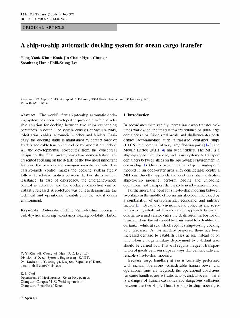
Mobile Harbor (MH) [4] has been studied. The MH is a
ship equipped with docking and crane systems to transport
containers between ships on the open-water environment in
ocean (Fig. 1). Once a large container ship is single-point
moored in an open-water area with considerable depth, a
MH can directly approach the container ship, establish
ship-to-ship mooring, perform loading and unloading
operations, and transport the cargo to nearby inner harbors.
Furthermore, the need for ship-to-ship mooring between
two ships in the middle of ocean has also been increased by
a combination of environmental, economic, and military
factors [5]. Because of environmental concerns and regu-
lations, single-hull oil tankers cannot approach to certain
coastal area and cannot enter the destination harbor for oil
transfer. Then, the oil should be transferred to a double-hull
oil tanker while at sea, which requires ship-to-ship docking
as a precursor. As for military purposes, there has been
increased demand to establish bases at sea instead of on
land when a large military deployment to a distant area
should be carried out. This will require frequent transpor-
tation of goods between ships in ways that demand safe and
reliable ship-to-ship mooring.
Because cargo handling at sea is currently performed
with manual operations, considerable human power and
operational time are required, the operational conditions
for cargo handling are not satisfactory, and, above all, there
is a danger of human casualties and dangerous collisions
between the two ships. Thus, the ship-to-ship mooring is
Y. Y. Kim � H. Chung � S. Han � P.-S. Lee (&)
Division of Ocean Systems Engineering, KAIST,
291 Daehak-ro, Yuseong-gu, Daejeon, Republic of Korea
e-mail: [email protected]
K.-J. Choi
Department of Mechatronics, Korea Polytechnics,
Changwon Campus 51-88 Woidongbanrim-ro,
Changwon, Republic of Korea
123
J Mar Sci Technol (2014) 19:360–375
DOI 10.1007/s00773-014-0256-3
only possible when a highly experienced special pilot is
present aboard the ship. Even so, the danger of ship-to-ship
mooring is always present. Consequently, it is necessary
and valuable to develop a ship-to-ship automatic ocean
docking system (S2S-ADS) to enable fast and safe ship-to-
ship docking, and to increase the efficiency of cargo han-
dling between ships in ocean.
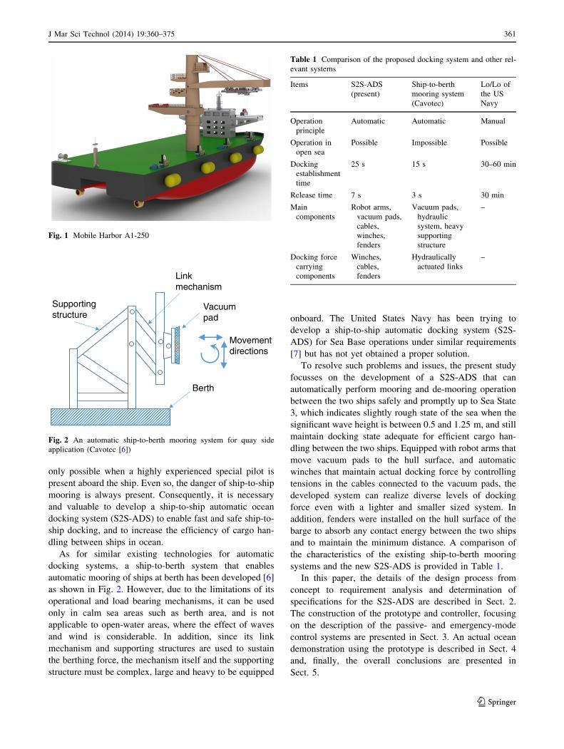
As for similar existing technologies for automatic
docking systems, a ship-to-berth system that enables
automatic mooring of ships at berth has been developed [6]
as shown in Fig. 2. However, due to the limitations of its
operational and load bearing mechanisms, it can be used
only in calm sea areas such as berth area, and is not
applicable to open-water areas, where the effect of waves
and wind is considerable. In addition, since its link
mechanism and supporting structures are used to sustain
the berthing force, the mechanism itself and the supporting
structure must be complex, large and heavy to be equipped
onboard. The United States Navy has been trying to
develop a ship-to-ship automatic docking system (S2S-
ADS) for Sea Base operations under similar requirements
[7] but has not yet obtained a proper solution.
To resolve such problems and issues, the present study
focusses on the development of a S2S-ADS that can
automatically perform mooring and de-mooring operation
between the two ships safely and promptly up to Sea State
3, which indicates slightly rough state of the sea when the
significant wave height is between 0.5 and 1.25 m, and still
maintain docking state adequate for efficient cargo han-
dling between the two ships. Equipped with robot arms that
move vacuum pads to the hull surface, and automatic
winches that maintain actual docking force by controlling
tensions in the cables connected to the vacuum pads, the
developed system can realize diverse levels of docking
force even with a lighter and smaller sized system. In
addition, fenders were installed on the hull surface of the
barge to absorb any contact energy between the two ships
and to maintain the minimum distance. A comparison of
the characteristics of the existing ship-to-berth mooring
systems and the new S2S-ADS is provided in Table 1.
In this paper, the details of the design process from
concept to requirement analysis and determination of
specifications for the S2S-ADS are described in Sect. 2.
The construction of the prototype and controller, focusing
on the description of the passive- and emergency-mode
control systems are presented in Sect. 3. An actual ocean
demonstration using the prototype is described in Sect. 4
and, finally, the overall conclusions are presented in
Sect. 5.
Fig. 1 Mobile Harbor A1-250
Vacuumpad
Linkmechanism
Supportingstructure
Berth
Movementdirections
Fig. 2 An automatic ship-to-berth mooring system for quay side
application (Cavotec [6])
Table 1 Comparison of the proposed docking system and other rel-
evant systems
Items S2S-ADS
(present)
Ship-to-berth
mooring system
(Cavotec)
Lo/Lo of
the US
Navy
Operation
principle
Automatic Automatic Manual
Operation in
open sea
Possible Impossible Possible
Docking
establishment
time
25 s 15 s 30–60 min
Release time 7 s 3 s 30 min
Main
components
Robot arms,
vacuum pads,
cables,
winches,
fenders
Vacuum pads,
hydraulic
system, heavy
supporting
structure
–
Docking force
carrying
components
Winches,
cables,
fenders
Hydraulically
actuated links
–
J Mar Sci Technol (2014) 19:360–375 361
123
2 System design of the automatic docking system
In this section, the overall system design of the S2S-ADS
for MHs as well as the prototype system for the ocean
demonstration is described.
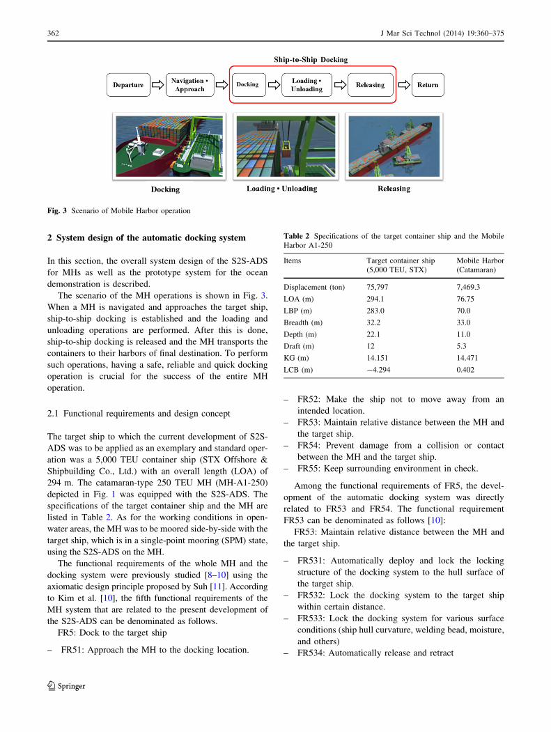
The scenario of the MH operations is shown in Fig. 3.
When a MH is navigated and approaches the target ship,
ship-to-ship docking is established and the loading and
unloading operations are performed. After this is done,
ship-to-ship docking is released and the MH transports the
containers to their harbors of final destination. To perform
such operations, having a safe, reliable and quick docking
operation is crucial for the success of the entire MH
operation.
2.1 Functional requirements and design concept
The target ship to which the current development of S2S-
ADS was to be applied as an exemplary and standard oper-
ation was a 5,000 TEU container ship (STX Offshore &
Shipbuilding Co., Ltd.) with an overall length (LOA) of
294 m. The catamaran-type 250 TEU MH (MH-A1-250)
depicted in Fig. 1 was equipped with the S2S-ADS. The
specifications of the target container ship and the MH are
listed in Table 2. As for the working conditions in open-
water areas, the MH was to be moored side-by-side with the
target ship, which is in a single-point mooring (SPM) state,
using the S2S-ADS on the MH.
The functional requirements of the whole MH and the
docking system were previously studied [8–10] using the
axiomatic design principle proposed by Suh [11]. According
to Kim et al. [10], the fifth functional requirements of the
MH system that are related to the present development of
the S2S-ADS can be denominated as follows.
FR5: Dock to the target ship
– FR51: Approach the MH to the docking location.
– FR52: Make the ship not to move away from an
intended location.
– FR53: Maintain relative distance between the MH and
the target ship.
– FR54: Prevent damage from a collision or contact
between the MH and the target ship.
– FR55: Keep surrounding environment in check.
Among the functional requirements of FR5, the devel-
opment of the automatic docking system was directly
related to FR53 and FR54. The functional requirement
FR53 can be denominated as follows [10]:
FR53: Maintain relative distance between the MH and
the target ship.
– FR531: Automatically deploy and lock the locking
structure of the docking system to the hull surface of
the target ship.
– FR532: Lock the docking system to the target ship
within certain distance.
– FR533: Lock the docking system for various surface
conditions (ship hull curvature, welding bead, moisture,
and others)
– FR534: Automatically release and retract
Fig. 3 Scenario of Mobile Harbor operation
Table 2 Specifications of the target container ship and the Mobile
Harbor A1-250
Items Target container ship
(5,000 TEU, STX)
Mobile Harbor
(Catamaran)
Displacement (ton) 75,797 7,469.3
LOA (m) 294.1 76.75
LBP (m) 283.0 70.0
Breadth (m) 32.2 33.0
Depth (m) 22.1 11.0
Draft (m) 12 5.3
KG (m) 14.151 14.471
LCB (m) -4.294 0.402
362 J Mar Sci Technol (2014) 19:360–375
123
– FR535: Limit relative movements and relative dis-
tances during docking.
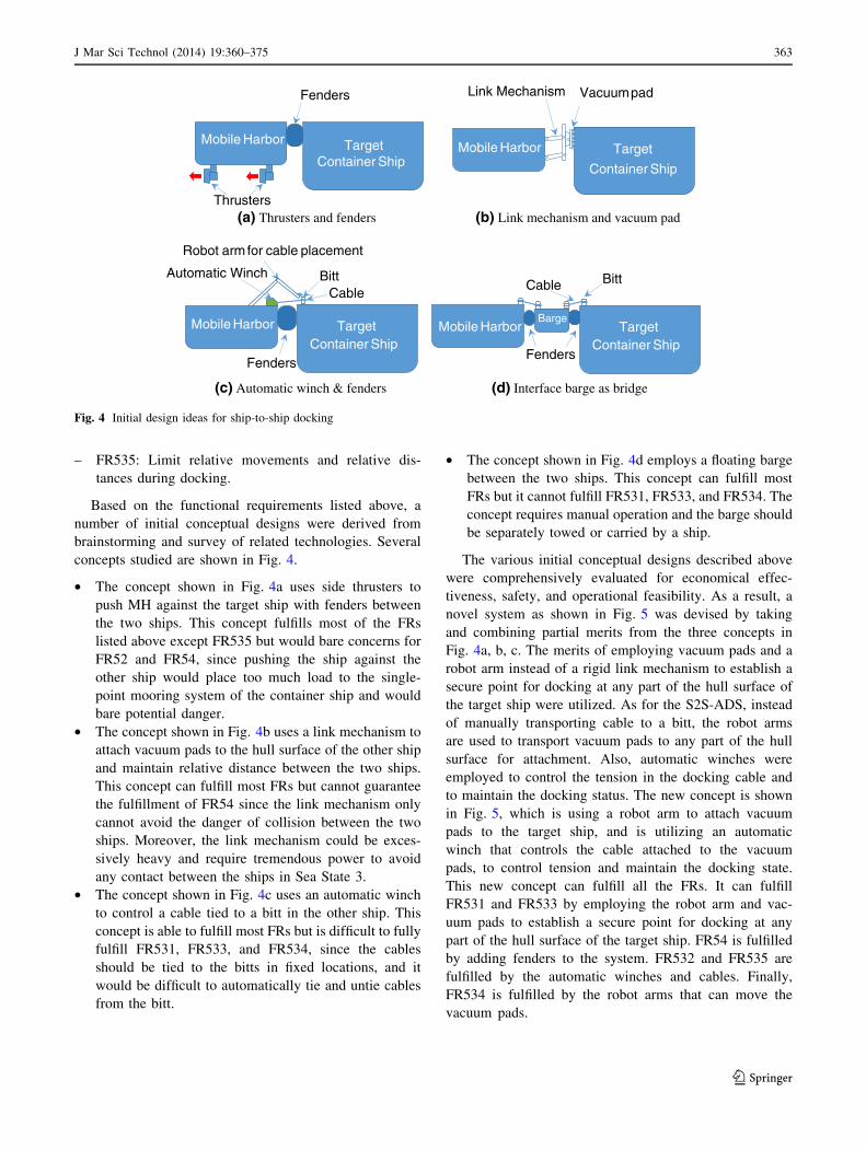
Based on the functional requirements listed above, a
number of initial conceptual designs were derived from
brainstorming and survey of related technologies. Several
concepts studied are shown in Fig. 4.
• The concept shown in Fig. 4a uses side thrusters to
push MH against the target ship with fenders between
the two ships. This concept fulfills most of the FRs
listed above except FR535 but would bare concerns for
FR52 and FR54, since pushing the ship against the
other ship would place too much load to the single-
point mooring system of the container ship and would
bare potential danger.
• The concept shown in Fig. 4b uses a link mechanism to
attach vacuum pads to the hull surface of the other ship
and maintain relative distance between the two ships.
This concept can fulfill most FRs but cannot guarantee
the fulfillment of FR54 since the link mechanism only
cannot avoid the danger of collision between the two
ships. Moreover, the link mechanism could be exces-
sively heavy and require tremendous power to avoid
any contact between the ships in Sea State 3.
• The concept shown in Fig. 4c uses an automatic winch
to control a cable tied to a bitt in the other ship. This
concept is able to fulfill most FRs but is difficult to fully
fulfill FR531, FR533, and FR534, since the cables
should be tied to the bitts in fixed locations, and it
would be difficult to automatically tie and untie cables
from the bitt.
• The concept shown in Fig. 4d employs a floating barge
between the two ships. This concept can fulfill most
FRs but it cannot fulfill FR531, FR533, and FR534. The
concept requires manual operation and the barge should
be separately towed or carried by a ship.
The various initial conceptual designs described above
were comprehensively evaluated for economical effec-
tiveness, safety, and operational feasibility. As a result, a
novel system as shown in Fig. 5 was devised by taking
and combining partial merits from the three concepts in
Fig. 4a, b, c. The merits of employing vacuum pads and a
robot arm instead of a rigid link mechanism to establish a
secure point for docking at any part of the hull surface of
the target ship were utilized. As for the S2S-ADS, instead
of manually transporting cable to a bitt, the robot arms
are used to transport vacuum pads to any part of the hull
surface for attachment. Also, automatic winches were
employed to control the tension in the docking cable and
to maintain the docking status. The new concept is shown
in Fig. 5, which is using a robot arm to attach vacuum
pads to the target ship, and is utilizing an automatic
winch that controls the cable attached to the vacuum
pads, to control tension and maintain the docking state.
This new concept can fulfill all the FRs. It can fulfill
FR531 and FR533 by employing the robot arm and vac-
uum pads to establish a secure point for docking at any
part of the hull surface of the target ship. FR54 is fulfilled
by adding fenders to the system. FR532 and FR535 are
fulfilled by the automatic winches and cables. Finally,
FR534 is fulfilled by the robot arms that can move the
vacuum pads.
Fenders
TargetContainer Ship
Mobile Harbor
Thrusters
Target
Container Ship
Mobile Harbor
Vacuumpad
Fenders
TargetContainer Ship
Mobile HarborBarge
Cable Bitt
TargetContainer Ship
Cable
Robot armfor cable placement
BittAutomatic Winch
Mobile Harbor
Fenders
(a) Thrusters and fenders (b) Link mechanism and vacuum pad
(c) Automatic winch & fenders (d) Interface barge as bridge
Link Mechanism
Fig. 4 Initial design ideas for ship-to-ship docking
J Mar Sci Technol (2014) 19:360–375 363
123
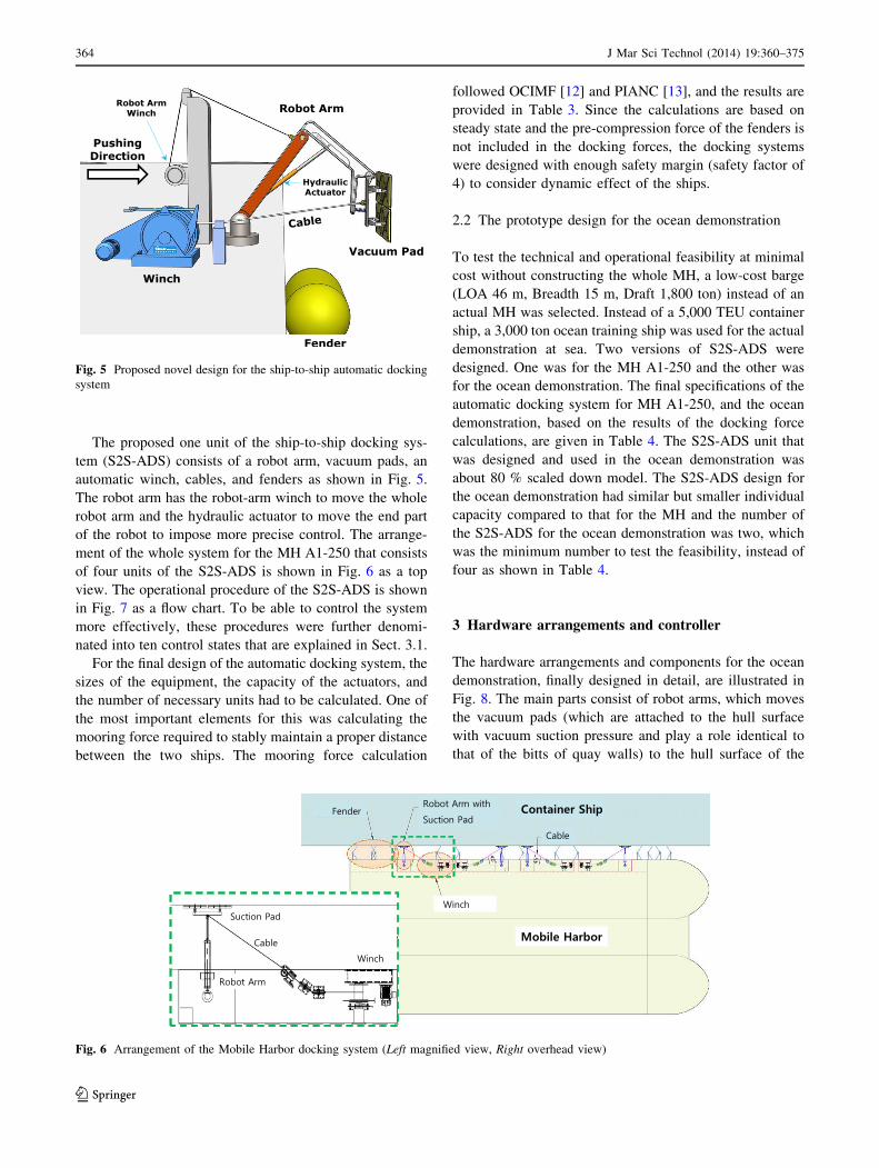
The proposed one unit of the ship-to-ship docking sys-
tem (S2S-ADS) consists of a robot arm, vacuum pads, an
automatic winch, cables, and fenders as shown in Fig. 5.
The robot arm has the robot-arm winch to move the whole
robot arm and the hydraulic actuator to move the end part
of the robot to impose more precise control. The arrange-
ment of the whole system for the MH A1-250 that consists
of four units of the S2S-ADS is shown in Fig. 6 as a top
view. The operational procedure of the S2S-ADS is shown
in Fig. 7 as a flow chart. To be able to control the system
more effectively, these procedures were further denomi-
nated into ten control states that are explained in Sect. 3.1.
For the final design of the automatic docking system, the
sizes of the equipment, the capacity of the actuators, and
the number of necessary units had to be calculated. One of
the most important elements for this was calculating the
mooring force required to stably maintain a proper distance
between the two ships. The mooring force calculation
followed OCIMF [12] and PIANC [13], and the results are
provided in Table 3. Since the calculations are based on
steady state and the pre-compression force of the fenders is
not included in the docking forces, the docking systems
were designed with enough safety margin (safety factor of
4) to consider dynamic effect of the ships.
2.2 The prototype design for the ocean demonstration
To test the technical and operational feasibility at minimal
cost without constructing the whole MH, a low-cost barge
(LOA 46 m, Breadth 15 m, Draft 1,800 ton) instead of an
actual MH was selected. Instead of a 5,000 TEU container
ship, a 3,000 ton ocean training ship was used for the actual
demonstration at sea. Two versions of S2S-ADS were
designed. One was for the MH A1-250 and the other was
for the ocean demonstration. The final specifications of the
automatic docking system for MH A1-250, and the ocean
demonstration, based on the results of the docking force
calculations, are given in Table 4. The S2S-ADS unit that
was designed and used in the ocean demonstration was
about 80 % scaled down model. The S2S-ADS design for
the ocean demonstration had similar but smaller individual
capacity compared to that for the MH and the number of
the S2S-ADS for the ocean demonstration was two, which
was the minimum number to test the feasibility, instead of
four as shown in Table 4.
3 Hardware arrangements and controller
The hardware arrangements and components for the ocean
demonstration, finally designed in detail, are illustrated in
Fig. 8. The main parts consist of robot arms, which moves
the vacuum pads (which are attached to the hull surface
with vacuum suction pressure and play a role identical to
that of the bitts of quay walls) to the hull surface of the
Fig. 5 Proposed novel design for the ship-to-ship automatic docking
system
Fig. 6 Arrangement of the Mobile Harbor docking system (Left magnified view, Right overhead view)
364 J Mar Sci Technol (2014) 19:360–375
123
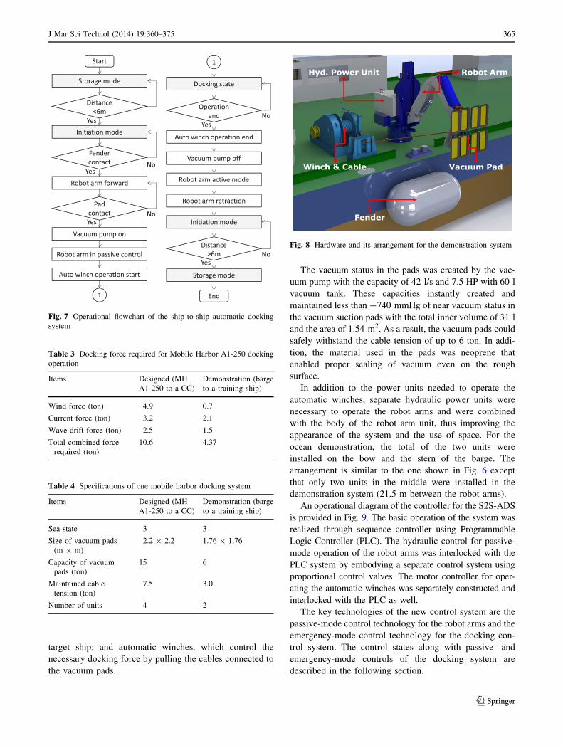
target ship; and automatic winches, which control the
necessary docking force by pulling the cables connected to
the vacuum pads.
The vacuum status in the pads was created by the vac-
uum pump with the capacity of 42 l/s and 7.5 HP with 60 l
vacuum tank. These capacities instantly created and
maintained less than -740 mmHg of near vacuum status in
the vacuum suction pads with the total inner volume of 31 l
and the area of 1.54 m2. As a result, the vacuum pads could
safely withstand the cable tension of up to 6 ton. In addi-
tion, the material used in the pads was neoprene that
enabled proper sealing of vacuum even on the rough
surface.
In addition to the power units needed to operate the
automatic winches, separate hydraulic power units were
necessary to operate the robot arms and were combined
with the body of the robot arm unit, thus improving the
appearance of the system and the use of space. For the
ocean demonstration, the total of the two units were
installed on the bow and the stern of the barge. The
arrangement is similar to the one shown in Fig. 6 except
that only two units in the middle were installed in the
demonstration system (21.5 m between the robot arms).
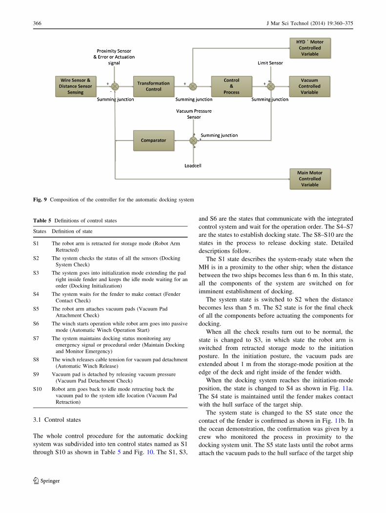
An operational diagram of the controller for the S2S-ADS
is provided in Fig. 9. The basic operation of the system was
realized through sequence controller using Programmable
Logic Controller (PLC). The hydraulic control for passive-
mode operation of the robot arms was interlocked with the
PLC system by embodying a separate control system using
proportional control valves. The motor controller for oper-
ating the automatic winches was separately constructed and
interlocked with the PLC as well.
The key technologies of the new control system are the
passive-mode control technology for the robot arms and the
emergency-mode control technology for the docking con-
trol system. The control states along with passive- and
emergency-mode controls of the docking system are
described in the following section.
Fig. 7 Operational flowchart of the ship-to-ship automatic docking
system
Fig. 8 Hardware and its arrangement for the demonstration system
Table 3 Docking force required for Mobile Harbor A1-250 docking
operation
Items Designed (MH
A1-250 to a CC)
Demonstration (barge
to a training ship)
Wind force (ton) 4.9 0.7
Current force (ton) 3.2 2.1
Wave drift force (ton) 2.5 1.5
Total combined force
required (ton)
10.6 4.37
Table 4 Specifications of one mobile harbor docking system
Items Designed (MH
A1-250 to a CC)
Demonstration (barge
to a training ship)
Sea state 3 3
Size of vacuum pads
(m 9 m)
2.2 9 2.2 1.76 9 1.76
Capacity of vacuum
pads (ton)
15 6
Maintained cable
tension (ton)
7.5 3.0
Number of units 4 2
J Mar Sci Technol (2014) 19:360–375 365
123
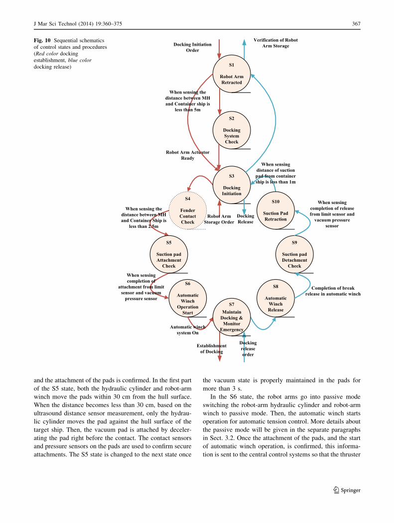
3.1 Control states
The whole control procedure for the automatic docking
system was subdivided into ten control states named as S1
through S10 as shown in Table 5 and Fig. 10. The S1, S3,
and S6 are the states that communicate with the integrated
control system and wait for the operation order. The S4–S7
are the states to establish docking state. The S8–S10 are the
states in the process to release docking state. Detailed
descriptions follow.
The S1 state describes the system-ready state when the
MH is in a proximity to the other ship; when the distance
between the two ships becomes less than 6 m. In this state,
all the components of the system are switched on for
imminent establishment of docking.
The system state is switched to S2 when the distance
becomes less than 5 m. The S2 state is for the final check
of all the components before actuating the components for
docking.
When all the check results turn out to be normal, the
state is changed to S3, in which state the robot arm is
switched from retracted storage mode to the initiation
posture. In the initiation posture, the vacuum pads are
extended about 1 m from the storage-mode position at the
edge of the deck and right inside of the fender width.
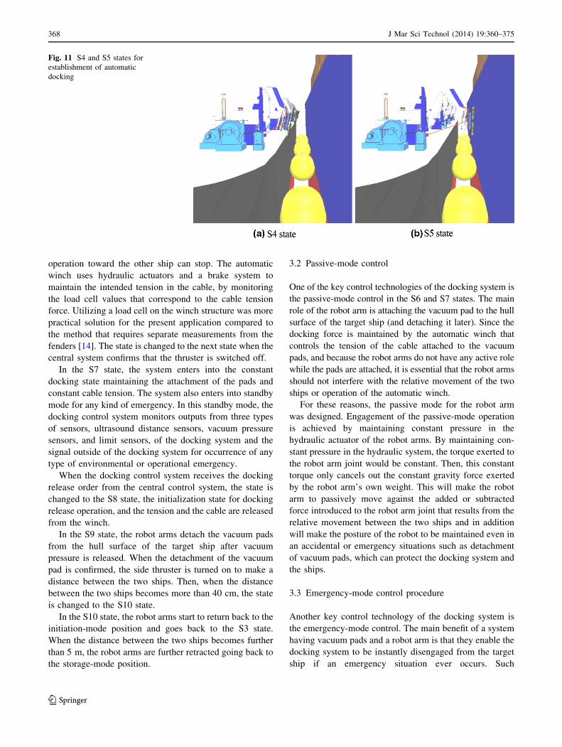
When the docking system reaches the initiation-mode
position, the state is changed to S4 as shown in Fig. 11a.
The S4 state is maintained until the fender makes contact
with the hull surface of the target ship.
The system state is changed to the S5 state once the
contact of the fender is confirmed as shown in Fig. 11b. In
the ocean demonstration, the confirmation was given by a
crew who monitored the process in proximity to the
docking system unit. The S5 state lasts until the robot arms
attach the vacuum pads to the hull surface of the target ship
Fig. 9 Composition of the controller for the automatic docking system
Table 5 Definitions of control states
States Definition of state
S1 The robot arm is retracted for storage mode (Robot Arm
Retracted)
S2 The system checks the status of all the sensors (Docking
System Check)
S3 The system goes into initialization mode extending the pad
right inside fender and keeps the idle mode waiting for an
order (Docking Initialization)
S4 The system waits for the fender to make contact (Fender
Contact Check)
S5 The robot arm attaches vacuum pads (Vacuum Pad
Attachment Check)
S6 The winch starts operation while robot arm goes into passive
mode (Automatic Winch Operation Start)
S7 The system maintains docking status monitoring any
emergency signal or procedural order (Maintain Docking
and Monitor Emergency)
S8 The winch releases cable tension for vacuum pad detachment
(Automatic Winch Release)
S9 Vacuum pad is detached by releasing vacuum pressure
(Vacuum Pad Detachment Check)
S10 Robot arm goes back to idle mode retracting back the
vacuum pad to the system idle location (Vacuum Pad
Retraction)
366 J Mar Sci Technol (2014) 19:360–375
123
and the attachment of the pads is confirmed. In the first part
of the S5 state, both the hydraulic cylinder and robot-arm
winch move the pads within 30 cm from the hull surface.
When the distance becomes less than 30 cm, based on the
ultrasound distance sensor measurement, only the hydrau-
lic cylinder moves the pad against the hull surface of the
target ship. Then, the vacuum pad is attached by deceler-
ating the pad right before the contact. The contact sensors
and pressure sensors on the pads are used to confirm secure
attachments. The S5 state is changed to the next state once
the vacuum state is properly maintained in the pads for
more than 3 s.
In the S6 state, the robot arms go into passive mode
switching the robot-arm hydraulic cylinder and robot-arm
winch to passive mode. Then, the automatic winch starts
operation for automatic tension control. More details about
the passive mode will be given in the separate paragraphs
in Sect. 3.2. Once the attachment of the pads, and the start
of automatic winch operation, is confirmed, this informa-
tion is sent to the central control systems so that the thruster
Fig. 10 Sequential schematics
of control states and procedures
(Red color docking
establishment, blue color
docking release)
J Mar Sci Technol (2014) 19:360–375 367
123
operation toward the other ship can stop. The automatic
winch uses hydraulic actuators and a brake system to
maintain the intended tension in the cable, by monitoring
the load cell values that correspond to the cable tension
force. Utilizing a load cell on the winch structure was more
practical solution for the present application compared to
the method that requires separate measurements from the
fenders [14]. The state is changed to the next state when the
central system confirms that the thruster is switched off.
In the S7 state, the system enters into the constant
docking state maintaining the attachment of the pads and
constant cable tension. The system also enters into standby
mode for any kind of emergency. In this standby mode, the
docking control system monitors outputs from three types
of sensors, ultrasound distance sensors, vacuum pressure
sensors, and limit sensors, of the docking system and the
signal outside of the docking system for occurrence of any
type of environmental or operational emergency.
When the docking control system receives the docking
release order from the central control system, the state is
changed to the S8 state, the initialization state for docking
release operation, and the tension and the cable are released
from the winch.
In the S9 state, the robot arms detach the vacuum pads
from the hull surface of the target ship after vacuum
pressure is released. When the detachment of the vacuum
pad is confirmed, the side thruster is turned on to make a
distance between the two ships. Then, when the distance
between the two ships becomes more than 40 cm, the state
is changed to the S10 state.
In the S10 state, the robot arms start to return back to the
initiation-mode position and goes back to the S3 state.
When the distance between the two ships becomes further
than 5 m, the robot arms are further retracted going back to
the storage-mode position.
3.2 Passive-mode control
One of the key control technologies of the docking system is
the passive-mode control in the S6 and S7 states. The main
role of the robot arm is attaching the vacuum pad to the hull
surface of the target ship (and detaching it later). Since the
docking force is maintained by the automatic winch that
controls the tension of the cable attached to the vacuum
pads, and because the robot arms do not have any active role
while the pads are attached, it is essential that the robot arms
should not interfere with the relative movement of the two
ships or operation of the automatic winch.
For these reasons, the passive mode for the robot arm
was designed. Engagement of the passive-mode operation
is achieved by maintaining constant pressure in the
hydraulic actuator of the robot arms. By maintaining con-
stant pressure in the hydraulic system, the torque exerted to
the robot arm joint would be constant. Then, this constant
torque only cancels out the constant gravity force exerted
by the robot arm’s own weight. This will make the robot
arm to passively move against the added or subtracted
force introduced to the robot arm joint that results from the
relative movement between the two ships and in addition
will make the posture of the robot to be maintained even in
an accidental or emergency situations such as detachment
of vacuum pads, which can protect the docking system and
the ships.
3.3 Emergency-mode control procedure
Another key control technology of the docking system is
the emergency-mode control. The main benefit of a system
having vacuum pads and a robot arm is that they enable the
docking system to be instantly disengaged from the target
ship if an emergency situation ever occurs. Such
Fig. 11 S4 and S5 states for
establishment of automatic
docking
368 J Mar Sci Technol (2014) 19:360–375
123
emergency actions can be activated from the emergency-
mode control system, which can take the required
sequential actions based on assessment of conditions being
monitored in the surrounding ocean environment, regard-
ing the movement of the two docked ships, and from the
docking system itself. Table 6 shows seven emergency
response procedures defined in the emergency-mode con-
trol system to identify and respond to various emergency
situations.
The E1 procedure is taken when an emergency situation
occurs during the docking system check procedure in the
control state S2. When any abnormal or false signal is
observed during the status check on the robot-arm
hydraulic cylinders or robot-arm winches, the system sends
an emergency signal to the central control system and
switches the state from S2 to S1.
The E2 procedure is taken when an emergency situation
occurs during the contact of the fenders to the hull surface
of the target ship while the docking system is in the S4
state. In the E2 procedure, the docking system sends an
emergency signal to the central control system and changes
the state from S4 to S7 to check all the signals from the
sensors and the outside. When the S7 state is reached, the
system is changed back to S3.
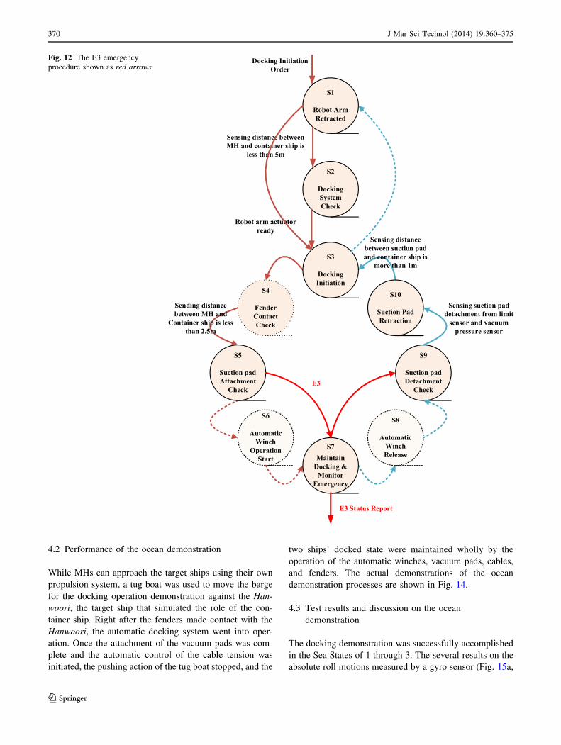
The E3 procedure (shown in Fig. 12) refers to the
emergency situation that can occur during the vacuum pad
attachment operation in the S5 control state. During this
operation, readings from the four contact sensors mounted
on the circumference of its pad array and a vacuum pres-
sure sensor inside are checked and an emergency signal is
sent when the attachment of the pad cannot be confirmed
from the sensor readings. In the E3 procedure, the control
state is first changed from S5 to S7 to gather all the signal
inputs. Then, the system is changed back to S3 after going
through the S9 and S10 states for proper retraction of pad.
The E4 procedure refers to the emergency situation that
can occur once the docking is established, and the docking
status is maintained in the S7 control state. When there is
an emergency signal from the crane system while main-
taining docking, the system sends an emergency signal to
the central control system, and the system is changed back
to S3 after going through S7, S8, S9, and S10.
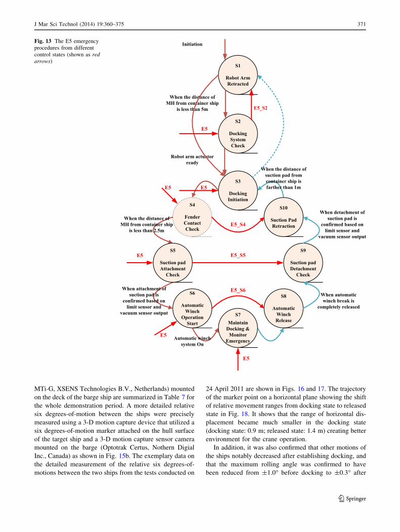
The E5 procedure (Fig. 13) refers to the emergency
situation that can occur from the outside of the MH due to
severe weather condition or other emergency. When this
emergency signal is received from the central control
system, the docking system goes back to either S1 or S3
from S7 state, depending on the severity of the emergency.
The environmental emergency signal can be generated by
occurrence of severe weather, abnormal impact from
unusually strong waves, and severe relative motions
between the two ships. Since the emergency signal from
the outside can occur at any control state, the E5 proce-
dures are defined from various states as shown in Fig. 13.
The E6 procedure refers to the emergency situation that
can occur from any malfunction of the sensors when the S7
state is maintained. The docking system detects any sensor
abnormalities by comparing the output value of each sensor
to the error limit range of each sensor. In the E7 state, the
system sends out its emergency state signal and maintains
the S7 state in the passive control mode so that the prob-
lematic sensor can be replaced.
The E7 procedure refers to any malfunction in the com-
munication between the central control system and other
docking systems. In the E7 procedure, the system sends out
emergency signals to the operator and maintains the S7 state.
4 Ocean demonstration
Two S2S-ADS are installed on a barge ship to demonstrate
and verify its full functional capability.
4.1 Venue of the ocean demonstration
The venue of the ocean demonstrations was in open-water
area at approximately 400 m from the quay walls of the
Korea Maritime University at the water depth of 30 m. The
Hanwoori, the target ship, was anchored using single-point
mooring. As for the sea weather, information provided by
the Korea Meteorological Administration (KMA) obtained
through Gwang-An light beacons, which are located
approximately 10 km from the venue of the demonstration,
was used as reference data for reading the sea state during
the ocean demonstration.
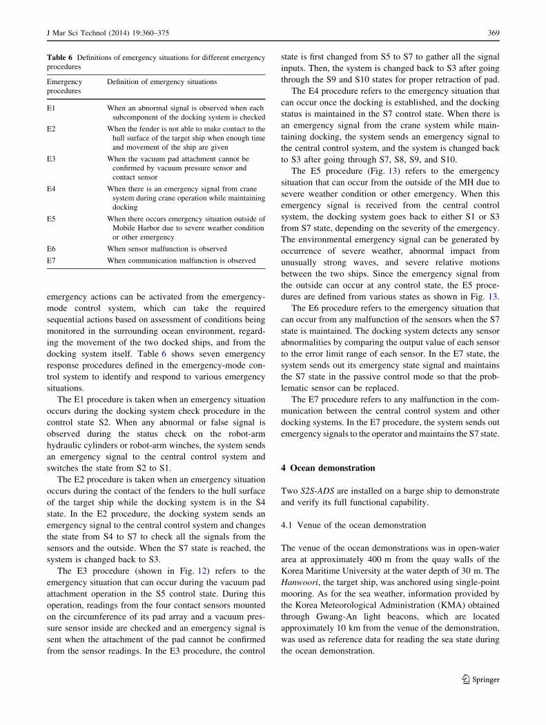
Table 6 Definitions of emergency situations for different emergency
procedures
Emergency
procedures
Definition of emergency situations
E1 When an abnormal signal is observed when each
subcomponent of the docking system is checked
E2 When the fender is not able to make contact to the
hull surface of the target ship when enough time
and movement of the ship are given
E3 When the vacuum pad attachment cannot be
confirmed by vacuum pressure sensor and
contact sensor
E4 When there is an emergency signal from crane
system during crane operation while maintaining
docking
E5 When there occurs emergency situation outside of
Mobile Harbor due to severe weather condition
or other emergency
E6 When sensor malfunction is observed
E7 When communication malfunction is observed
J Mar Sci Technol (2014) 19:360–375 369
123
4.2 Performance of the ocean demonstration
While MHs can approach the target ships using their own
propulsion system, a tug boat was used to move the barge
for the docking operation demonstration against the Han-
woori, the target ship that simulated the role of the con-
tainer ship. Right after the fenders made contact with the
Hanwoori, the automatic docking system went into oper-
ation. Once the attachment of the vacuum pads was com-
plete and the automatic control of the cable tension was
initiated, the pushing action of the tug boat stopped, and the
two ships’ docked state were maintained wholly by the
operation of the automatic winches, vacuum pads, cables,
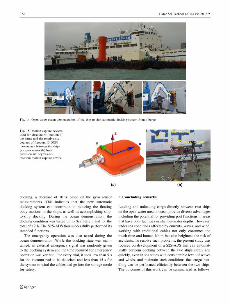
and fenders. The actual demonstrations of the ocean
demonstration processes are shown in Fig. 14.
4.3 Test results and discussion on the ocean
demonstration
The docking demonstration was successfully accomplished
in the Sea States of 1 through 3. The several results on the
absolute roll motions measured by a gyro sensor (Fig. 15a,
Fig. 12 The E3 emergency
procedure shown as red arrows
370 J Mar Sci Technol (2014) 19:360–375
123
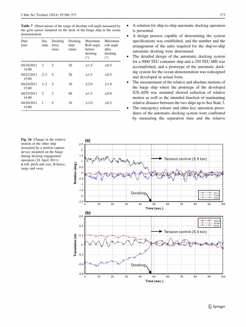
MTi-G, XSENS Technologies B.V., Netherlands) mounted
on the deck of the barge ship are summarized in Table 7 for
the whole demonstration period. A more detailed relative
six degrees-of-motion between the ships were precisely
measured using a 3-D motion capture device that utilized a
six degrees-of-motion marker attached on the hull surface
of the target ship and a 3-D motion capture sensor camera
mounted on the barge (Optotrak Certus, Nothern Digial
Inc., Canada) as shown in Fig. 15b. The exemplary data on
the detailed measurement of the relative six degrees-of-
motions between the two ships from the tests conducted on
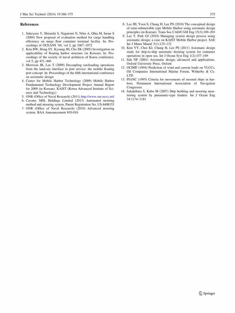
24 April 2011 are shown in Figs. 16 and 17. The trajectory
of the marker point on a horizontal plane showing the shift
of relative movement ranges from docking state to released
state in Fig. 18. It shows that the range of horizontal dis-
placement became much smaller in the docking state
(docking state: 0.9 m; released state: 1.4 m) creating better
environment for the crane operation.
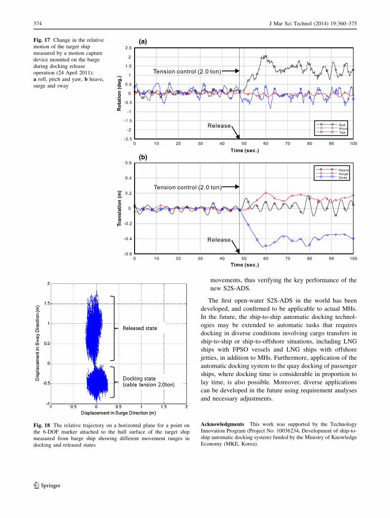
In addition, it was also confirmed that other motions of
the ships notably decreased after establishing docking, and
that the maximum rolling angle was confirmed to have
been reduced from ±1.0� before docking to ±0.3� after
Fig. 13 The E5 emergency
procedures from different
control states (shown as red
arrows)
J Mar Sci Technol (2014) 19:360–375 371
123
docking, a decrease of 70 % based on the gyro sensor
measurements. This indicates that the new automatic
docking system can contribute to reducing the floating
body motions in the ships, as well as accomplishing ship-
to-ship docking. During the ocean demonstration, the
docking condition was tested up to Sea State 3 and for the
total of 12 h. The S2S-ADS thus successfully performed its
intended functions.
The emergency operation was also tested during the
ocean demonstration. While the docking state was main-
tained, an external emergency signal was randomly given
to the docking system and the time required for emergency
operation was verified. For every trial, it took less than 5 s
for the vacuum pad to be detached and less than 15 s for
the system to wind the cables and go into the storage mode
for safety.
5 Concluding remarks
Loading and unloading cargo directly between two ships
on the open-water area in ocean provide diverse advantages
including the potential for providing port functions in areas
that have poor facilities or shallow-water depths. However,
under sea conditions affected by currents, waves, and wind;
working with traditional cables not only consumes too
much time and human labor, but also heightens the risk of
accidents. To resolve such problems, the present study was
focused on development of a S2S-ADS that can automat-
ically perform docking between the two ships safely and
quickly, even in sea states with considerable level of waves
and winds, and maintain such conditions that cargo han-
dling can be performed efficiently between the two ships.
The outcomes of this work can be summarized as follows:
Fig. 14 Open-water ocean demonstration of the ship-to-ship automatic docking system from a barge
Fig. 15 Motion capture devices
used for absolute roll motion of
the barge and the relative six
degrees-of-freedom (6-DOF)
movements between the ships
(a) gyro sensor (b) high
precision six degrees-of-
freedom motion capture device
372 J Mar Sci Technol (2014) 19:360–375
123
• A solution for ship-to-ship automatic docking operation
is presented.
• A design process capable of determining the system
specifications was established, and the number and the
arrangement of the units required for the ship-to-ship
automatic docking were determined.
• The detailed design of the automatic docking system
for a 5000 TEU container ship and a 250 TEU MH was
accomplished, and a prototype of the automatic dock-
ing system for the ocean demonstration was redesigned
and developed in actual form.
• The measurement of the relative and absolute motions of
the barge ship where the prototype of the developed
S2S-ADS was mounted showed reduction of relative
motion as well as the intended function of maintaining
relative distance between the two ships up to Sea State 3.
• The emergency release and other key operation proce-
dures of the automatic docking system were confirmed
by measuring the separation time and the relative
(a)
(b)
Fig. 16 Change in the relative
motion of the other ship
measured by a motion capture
device mounted on the barge
during docking engagement
operation (24 April 2011):
a roll, pitch and yaw; b heave,
surge and sway
Table 7 Observations of the range of absolute roll angle measured by
the gyro sensor mounted on the deck of the barge ship in the ocean
demonstration
Date
time
Sea
state
Docking
force
(ton)
Docking
time
(min)
Maximum
Roll angle
before
docking
(�)
Maximum
roll angle
after
docking
(�)
04/18/2011
14:00
3 2 20 ±1.5 ±0.5
04/21/2011
15:00
2–3 5 20 ±1.5 ±0.5
04/24/2011
15:00
1–2 2 10 ±2.0 ±1.0
04/25/2011
14:00
2 2 60 ±1.5 ±0.8
04/26/2011
14:00
1 5 10 ±1.0 ±0.3
J Mar Sci Technol (2014) 19:360–375 373
123
movements, thus verifying the key performance of the
new S2S-ADS.
The first open-water S2S-ADS in the world has been
developed, and confirmed to be applicable to actual MHs.
In the future, the ship-to-ship automatic docking technol-
ogies may be extended to automatic tasks that requires
docking in diverse conditions involving cargo transfers in
ship-to-ship or ship-to-offshore situations, including LNG
ships with FPSO vessels and LNG ships with offshore
jetties, in addition to MHs. Furthermore, application of the
automatic docking system to the quay docking of passenger
ships, where docking time is considerable in proportion to
lay time, is also possible. Moreover, diverse applications
can be developed in the future using requirement analyses
and necessary adjustments.
Acknowledgments This work was supported by the Technology
Innovation Program (Project No: 10036234, Development of ship-to-
ship automatic docking system) funded by the Ministry of Knowledge
Economy (MKE, Korea).
(a)
(b)
Fig. 17 Change in the relative
motion of the target ship
measured by a motion capture
device mounted on the barge
during docking release
operation (24 April 2011):
a roll, pitch and yaw, b heave,
surge and sway
Fig. 18 The relative trajectory on a horizontal plane for a point on
the 6-DOF marker attached to the hull surface of the target ship
measured from barge ship showing different movement ranges in
docking and released states
374 J Mar Sci Technol (2014) 19:360–375
123
References
1. Sukeyasu Y, Shiraishi S, Nagatomi N, Nitta A, Ohta M, Inoue S
(2004) New proposal of evaluation method for cargo handling
efficiency on mega float container terminal facility. In: Pro-
ceedings of OCEANS ’04, vol 2, pp 1067–1072
2. Kim BW, Hong SY, Kyoung JH, Cho SK (2005) Investigation on
applicability of floating harbor structure (in Korean). In: Pro-
ceedings of the society of naval architects of Korea conference,
vol 5, pp 451–460
3. Morrison JR, Lee T (2009) Decoupling (un)loading operations
from the land-sea interface in port service: the mobile floating
port concept. In: Proceedings of the fifth international conference
on axiomatic design
4. Center for Mobile Harbor Technology (2009) Mobile Harbor
Fundamental Technology Development Project Annual Report
for 2009 (in Korean). KAIST (Korea Advanced Institute of Sci-
ence and Technology)
5. ONR (Office of Naval Research) (2011) http://www.onr.navy.mil
6. Cavotec MSL Holdings Limited (2013) Automated mooring
method and mooring system, Patent Registration No. US-8408153
7. ONR (Office of Naval Research) (2010) Advanced mooring
system. BAA Announcement #10-016
8. Lee JH, Yoon S, Chung H, Lee PS (2010) The conceptual design
of semi-submersible type Mobile Harbor using axiomatic design
principles (in Korean). Trans Soc CAD/CAM Eng 15(3):189–203
9. Lee T, Park GJ (2010) Managing system design process using
axiomatic design; a case on KAIST Mobile Harbor project. SAE
Int J Mater Manuf 3(1):125–132
10. Kim YY, Choi KJ, Chung H, Lee PS (2011) Axiomatic design
study for ship-to-ship automatic docking system for container
operations in open sea. Int J Ocean Syst Eng 1(2):157–169
11. Suh NP (2001) Axiomatic design; advanced and applications.
Oxford University Press, Oxford
12. OCIMF (1994) Prediction of wind and current loads on VLCCs,
Oil Companies International Marine Forum, Witherby & Co.
LTD
13. PIANC (1995) Criteria for movements of moored ships in har-
bors, Permanent International Association of Navigation
Congresses
14. Sakakibara S, Kubo M (2007) Ship berthing and mooring mon-
itoring system by pneumatic-type fenders. Int J Ocean Eng
34:1174–1181
J Mar Sci Technol (2014) 19:360–375 375
123