msc. thesis İŞler analysis and comparison of radio access techniques...
TRANSCRIPT

UNIVERSITY OF CUKUROVA INSTITUTE OF NATURAL AND APPLIED SCIENCE
MSc. THESIS
Erkan İŞLER
ANALYSIS AND COMPARISON OF RADIO ACCESS TECHNIQUES FOR UMTS AND LTE
DEPARTMENT OF ELECTRICAL AND ELECTRONICS ENGINEERING
ADANA, 2010

UNIVERSITY OF ÇUKUROVA
INSTITUE OF NATURAL AND APPLIED SCIENCE
ANALYSIS AND COMPARISON OF RADIO ACCESS TECHNIQUES FOR UMTS AND LTE
Erkan İŞLER
MSc THESIS
DEPARTMENT OF ELECTRICAL AND ELECTRONICS ENGİNEERİNG
We certified that the thesis titled above was reviewed and approved
for the award of degree of the Master of Science by the board of jury on 02 /02 /2010.
Signature………. Signature………. Signature………. Assoc. Prof.Dr. Turgut İKİZ Prof. Dr. Hamit SERBEST Asst. Prof. Dr. Mustafa ORAL Supervisor Member Member This MSc Thesis is performed in Department of Institute of Basic And Applied Sciences of Cukurova University. Registration Number: Prof. Dr. İlhami YEĞİNGİL Director Institute of Basic and Applied Sciences
Not: The usage of the presented specific declerations, tables, figures, and photographs either in this thesis or in any other reference without citiation is subject to “The law of Arts and Intellectual Products” number of 5846 of Turkish Republic
I
ABSTRACT
MSc THESIS
Erkan İŞLER
Erkan İŞLER
UNIVERSITY OF ÇUKUROVA
INSTITUTE OF NATURAL AND APPLIED SCIENCES
DEPARTMENT OF ELECTRICAL AND ELECTRONICS ENGINEERING
Supervisor: Assoc. Prof. Dr. Turgut İKİZ
Year: 2010, Page: 92
Jury: Prof. Dr Hamit SERBEST
Assoc. Prof. Dr. Turgut İKİZ
Asst. Prof. Dr. Mustafa ORAL
Universal Mobile Telecommunications System (UMTS) is one of the third-generation (3G) mobile telecommunications technologies. Currently, UMTS uses WCDMA (Wideband Code Division Multiple Access) as the radio access technique.
LTE (Long Term Evolution) is one of the fourth generation (4G) technologies. It is introduced in 3rd Generation Partnership Project (3GPP) Release 8. In LTE the downlink radio access technique is based on the Orthogonal Frequency Division Multiple Access (OFDMA) and the uplink radio access technique is based on the Single Carrier Frequency Division Multiple Access (SC-FDMA).
Main goal of this study is to analysis UMTS and LTE systems and compare and analysis their radio access techniques.
Keywords: UMTS, LTE, SC-FDMA, OFDMA, TDMA
ANALYSIS AND COMPARISON OF RADIO ACCESS TECHNIQUES FOR UMTS AND LTE
II
ÖZ
YÜKSEK LİSANS TEZİ
Erkan İŞLER
ÇUKUROVA ÜNİVERSİTESİ
FEN BİLİMLERİ ENSTİTÜSÜ
ELEKTRİK ELEKTRONİK MÜHENDİSLİĞİ ANABİLİM DALI
Danışman: Doç. Dr. Turgut İKİZ
Yıl: 2010, Sayfa:92
Jüri: Prof. Dr Hamit SERBEST
Doç. Dr. Turgut İKİZ
Yrd. Doç. Dr. Mustafa ORAL
Evrensel Mobil Haberleşme Sistemi (UMTS), 3. Nesil haberleşme teknolojilerinden birisidir. UMTS radyo erişim tekniği olarak WCDMA kullanmaktadır.
Uzun Vadeli Evrim (LTE) 3. Nesil haberleşme teknolojilerinden birisidir. LTE, 3GPP (3. Nesil Ortaklık Projesi) 8. bildiri olarak tanıtılmıştır. LTE’ in radyo erişim tekniği UMTS’ e göre farklıdır. LTE aşağı yönlü iletimde Ortogonal Frekans Bölmeli Çoklu Erişim (OFDMA) ve yukarı yönlü iletimde Tek Taşıyıcılı Frekans Bölmeli Çoklu Erişim (SC-FDMA) tekniklerini kullanır.
Bu çalışmanın amacı UMTS ve LTE sistemlerinin analizini ve bu sistemlerde kullanılan radyo erişim tekniklerinin karşılaştırmasını ve analizini yapmaktır.
Anahtar Kelimeler: UMTS, LTE, SC-FDMA, OFDMA, TDMA
UMTS VE LTE ANALİZİ VE RADYO ERİŞİM TEKNİKLERİNİN KARŞILAŞTIRILMASI

III
ACKNOWLEDGEMENTS
I would like to express my gratitude to my advisor Assoc. Prof. Dr. Turgut
İKİZ for his guidance, support and encouragement. Without his guidance and
encouragement, I would not be able to this.
I am also very thankful to my wife Arzu İŞLER for her continuous and
everlasting love, attention and moral support.
IV
CONTENTS PAGE
ABSTRACT ............................................................................................................. I
ÖZ ........................................................................................................................... II
ACKNOWLEDGEMENTS .................................................................................... III
CONTENTS ...........................................................................................................IV
ABBREVIATONS ............................................................................................... VII
TABLE INDEX ......................................................................................................XI
FIGURE INDEX .................................................................................................. XII
1.INTRODUCTION ................................................................................................. 1
2.OVERVIEW OF THE CELLULAR TECHNOLOGY ........................................... 3
2.1.First Generation Systems................................................................................. 3
2.2.Second Generation Systems ............................................................................ 5
2.2.1.GSM ...................................................................................................... 5
2.2.2.CDMA ................................................................................................. 12
2.2.3.D-AMPS .............................................................................................. 12
2.3.Third Generation Systems ............................................................................. 13
2.3.1.CDMA2000.......................................................................................... 13
2.3.2.UMTS (Universal Mobile Telecommunications System) ...................... 14
2.4.Fourth Generation Systems ........................................................................... 16
2.4.1.UMB .................................................................................................... 16
2.4.2.WiMax ................................................................................................. 17
2.4.3.LTE ...................................................................................................... 18
3.UMTS ................................................................................................................. 21
3.1.Introduction .................................................................................................. 21
3.2.Architecture of UMTS Network .................................................................... 21
3.2.1.User Equipment Domain ...................................................................... 22
3.2.2.Infrastructure Domain .......................................................................... 23
3.3.Universal Terrestrial Radio Access Network (UTRAN) ................................ 24
3.3.1.Radio Network Sub-systems (RNS) ...................................................... 27
3.3.2.The Radio Network Controller (RNC) .................................................. 27
V
3.3.3.The Node B (Base Station) ................................................................... 28
3.4.UMTS Core Network Architecture and Evolution Core Network .................. 28
3.4.1.Release ’99 Core Network Elements..................................................... 28
3.4.2.Release 5 Core Network and IP Multimedia Sub-system ...................... 30
3.5.UMTS Radio Interface Protocols .................................................................. 32
3.5.1.Logical Channels .................................................................................. 34
3.5.2.Transport Channels............................................................................... 35
3.5.3.Physical Channels ................................................................................ 36
3.6.Physical Layer .............................................................................................. 37
3.6.1.Cell Structure ....................................................................................... 38
3.6.2.Power Control ...................................................................................... 39
3.6.3.Capacity and Capacity Management ..................................................... 42
3.6.4.Multipath Diversity and Rake Receiver ................................................ 44
3.6.5.Handovers in UMTS ............................................................................ 47
4.LTE ..................................................................................................................... 49
4.1.Introduction .................................................................................................. 49
4.2.Architecture of LTE Network ........................................................................ 50
4.2.1.Core Network ....................................................................................... 52
4.2.2.Access Network ................................................................................... 53
4.3.LTE Channels for Downlink ......................................................................... 55
4.3.1.LTE Logical Channels for Downlink .................................................... 55
4.3.2.LTE Transport Channels for Downlink ................................................. 56
4.3.3.LTE Physical Channels for Downlink ................................................... 57
4.4.LTE Channels for Uplink .............................................................................. 58
4.4.1.LTE Logical Channels Uplink .............................................................. 59
4.4.2.LTE Transport Channels for Uplink ..................................................... 60
4.4.3.LTE Physical Channels for Uplink ....................................................... 60
4.5.Multiple Antenna Techniques in LTE............................................................ 61
4.5.1.LTE MIMO .......................................................................................... 61
5.COMPARISON OF RADIO ACCESS TECNIQUES .......................................... 63
5.1.Radio Access Technique for UMTS .............................................................. 63

VI
5.1.1.Spread Spectrum .................................................................................. 65
5.1.2.Channelization Code ............................................................................ 66
5.1.3.Scrambling Code .................................................................................. 68
5.1.4.Duplexing Method................................................................................ 71
5.1.5.Data Modulation for WCDMA ............................................................. 72
5.2.Radio Access Technique for LTE .................................................................. 74
5.2.1.OFDMA ............................................................................................... 74
5.2.2.SCFDMA ............................................................................................. 81
5.2.3.Data Modulation for OFDMA and SC-FDMA ...................................... 85
5.2.4.Comparison of OFDMA and SC-FDMA .............................................. 86
5.3.Comparison of WCDMA and OFDMA – SC-FDMA .................................... 88
6.CONCLUSION ................................................................................................... 89
REFERENCES ....................................................................................................... 90
RESUME ............................................................................................................... 92

VII
ABBREVIATONS
1G : First Generation Cellular System 2G : Second Generation Cellular System 3G : Third Generation Cellular System 3GPP2 : Third Generation Partnership Project 2 4G : Fourth Generation Cellular System AAL2 : ATM Adaptation Layer type 2 AGW : Access Gateway AMC : Adaptive Modulation and Coding AMPS : Advanced Mobile Phone Service AN : Access Network AS : Access Stratum ATM: : Asynchronous Transfer Mode AUC : Authentication Center BCCH : Broadcast Control Channel BCH : Broadcast Channel BLER : Block Error Ratio BPSK : Binary Phase Shift Keying BS : Base Station BSC : Base Station Controller BSS : Base Station System BTS : Base Transceiver Station CAN : Converged Access Network CCCH : Common Control Channel CDMA : Code Division Multiple Access CN : Core Network CP : Cyclic Prefix CPCH : Common Packet Channel CS : Circuit Switched CTCH : Common Traffic Channel D-AMPS : Digital Advanced Mobile Phone System DCCH : Dedicated Control Channel DCH : Dedicated Channel DFT : Discrete Fourier Transform DL : Downlink DL-SCH : Downlink Shared Channel DPCCH : Dedicated Physical Control Channel DPDCH : Dedicated Physical Data Channel
VIII
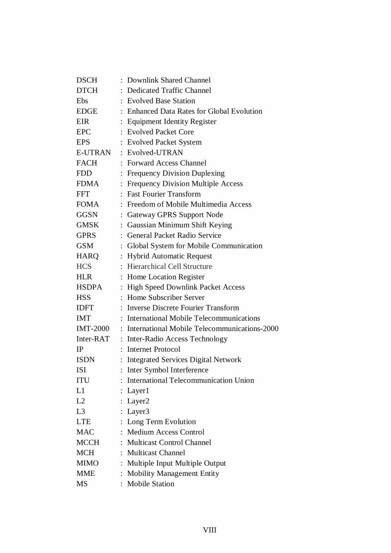
DSCH : Downlink Shared Channel DTCH : Dedicated Traffic Channel Ebs : Evolved Base Station EDGE : Enhanced Data Rates for Global Evolution EIR : Equipment Identity Register EPC : Evolved Packet Core EPS : Evolved Packet System E-UTRAN : Evolved-UTRAN FACH : Forward Access Channel FDD : Frequency Division Duplexing FDMA : Frequency Division Multiple Access FFT : Fast Fourier Transform FOMA : Freedom of Mobile Multimedia Access GGSN : Gateway GPRS Support Node GMSK : Gaussian Minimum Shift Keying GPRS : General Packet Radio Service GSM : Global System for Mobile Communication HARQ : Hybrid Automatic Request HCS : Hierarchical Cell Structure HLR : Home Location Register HSDPA : High Speed Downlink Packet Access HSS : Home Subscriber Server IDFT : Inverse Discrete Fourier Transform IMT : International Mobile Telecommunications IMT-2000 : International Mobile Telecommunications-2000 Inter-RAT : Inter-Radio Access Technology IP : Internet Protocol ISDN : Integrated Services Digital Network ISI : Inter Symbol Interference ITU : International Telecommunication Union L1 : Layer1 L2 : Layer2 L3 : Layer3 LTE : Long Term Evolution MAC : Medium Access Control MCCH : Multicast Control Channel MCH : Multicast Channel MIMO : Multiple Input Multiple Output MME : Mobility Management Entity MS : Mobile Station
IX
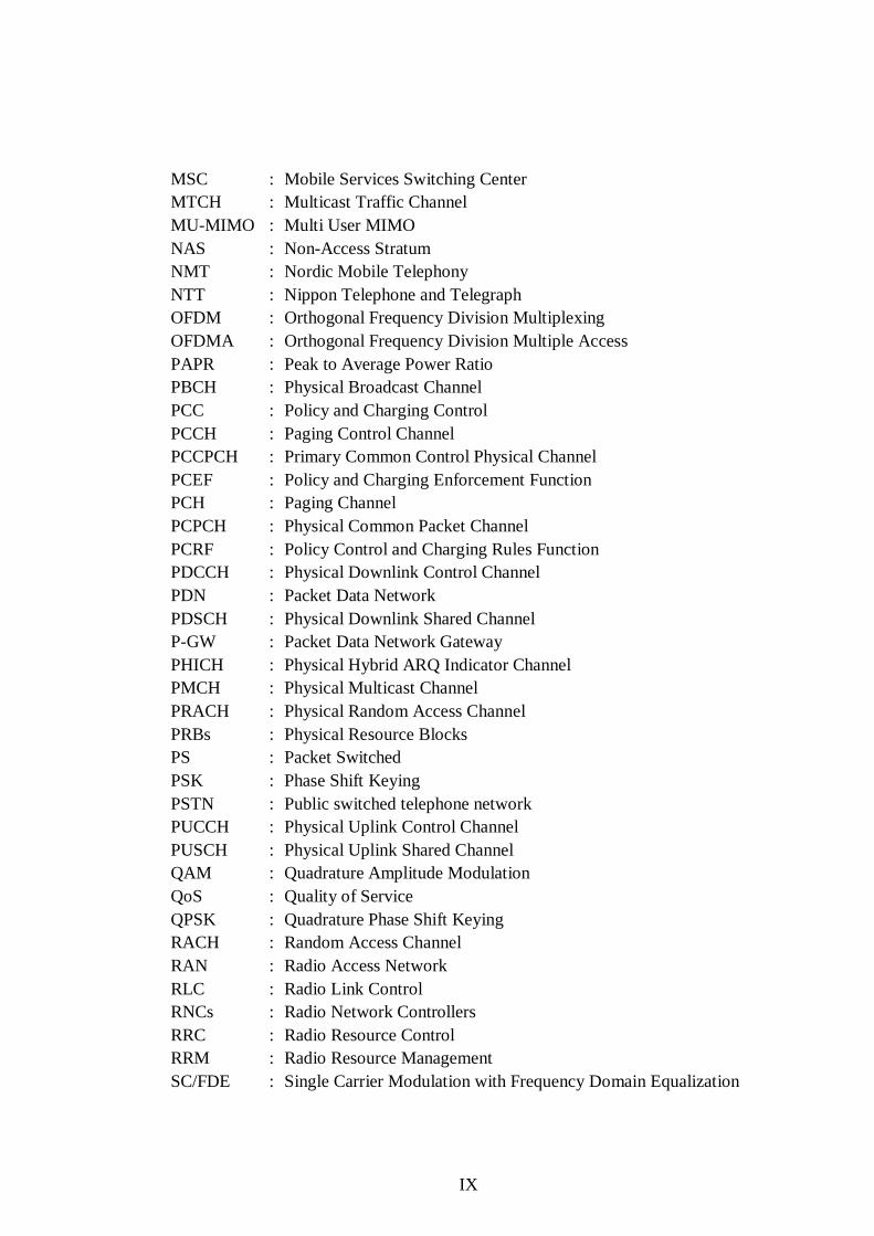
MSC : Mobile Services Switching Center MTCH : Multicast Traffic Channel MU-MIMO : Multi User MIMO NAS : Non-Access Stratum NMT : Nordic Mobile Telephony NTT : Nippon Telephone and Telegraph OFDM : Orthogonal Frequency Division Multiplexing OFDMA : Orthogonal Frequency Division Multiple Access PAPR : Peak to Average Power Ratio PBCH : Physical Broadcast Channel PCC : Policy and Charging Control PCCH : Paging Control Channel PCCPCH : Primary Common Control Physical Channel PCEF : Policy and Charging Enforcement Function PCH : Paging Channel PCPCH : Physical Common Packet Channel PCRF : Policy Control and Charging Rules Function PDCCH : Physical Downlink Control Channel PDN : Packet Data Network PDSCH : Physical Downlink Shared Channel P-GW : Packet Data Network Gateway PHICH : Physical Hybrid ARQ Indicator Channel PMCH : Physical Multicast Channel PRACH : Physical Random Access Channel PRBs : Physical Resource Blocks PS : Packet Switched PSK : Phase Shift Keying PSTN : Public switched telephone network PUCCH : Physical Uplink Control Channel PUSCH : Physical Uplink Shared Channel QAM : Quadrature Amplitude Modulation QoS : Quality of Service QPSK : Quadrature Phase Shift Keying RACH : Random Access Channel RAN : Radio Access Network RLC : Radio Link Control RNCs : Radio Network Controllers RRC : Radio Resource Control RRM : Radio Resource Management SC/FDE : Single Carrier Modulation with Frequency Domain Equalization

X
SCCPCH : Secondary Common Control Physical Channel SCFDMA : Single Carrier Frequency Division Multiple Access SGSN : Serving GPRS Support Node S-GW : Serving Gateway SIM : Subscriber Identity Module SIR : Signal to Interference Ratio SNR : Signal to Noise Ratio SS : Switching System SU-MIMO : Single User MIMO TACS : Total Access Communications System TDD : Time-Division Duplexing TDMA : Time Division Multiple Access UE : User Equipment UL : Uplink UL-SCH : Uplink Shared Channel UMTS : The Universal Mobile Telecommunications System USIM : Universal SIM UTRAN : UMTS Terrestrial Radio Access Network VLR : Visitor Location Register VoIP : Voice over IP WCDMA : Wideband Code Division Multiple Access
XI
TABLE INDEX PAGE
Table 2.1. Analog Cellular Standards ........................................................................ 4
Table 5.1. Available Downlink Bandwidth is Divided into Physical Resource Blocks
............................................................................................................................... 79

XII
FIGURE INDEX PAGE
Figure 2.1. GSM System model ................................................................................ 6
Figure 2.2. A Cell ..................................................................................................... 7
Figure 2.3. A BSC and BTS ...................................................................................... 8
Figure 2.4. LTE Multiple Access Schemes (HOLMA, H, TOSKALA, A, 2009) ..... 19
Figure 2.5. Evolution Time Frame for Planned 3GPP Systems ................................ 20
Figure 3.1. UMTS Architecture Domains and Reference Points .............................. 22
Figure 3.2. UMTS high-level system architecture ................................................... 25
Figure 3.3. UTRAN Architecture ............................................................................ 26
Figure 3.4. Release ’99 UMTS core network structure (HOLMA, H, TOSKALA, A,
2007) .................................................................................................... 29
Figure 3.5. Release 5 UMTS core network architecture (HOLMA, H, TOSKALA, A,
2007) .................................................................................................... 31
Figure 3.6. UMTS Radio Interface Protocol Architecture ........................................ 33
Figure 3.7. UMTS Channel Mapping ...................................................................... 37
Figure 3.8. UMTS Hierarchical Cell Structure (CHEN, H, 2007) ............................ 39
Figure 3.9. Near-far Problem Example (CHEN, H, 2007) ....................................... 41
Figure 3.10. UMTS Power Control Loops ............................................................... 42
Figure 3.11. Admission Control .............................................................................. 44
Figure 3.12. Multipath propagation (CHEN, H, 2007)............................................. 45
Figure 3.13. Fast (Rayleigh) Fading. ....................................................................... 46
Figure 3.14. Rake receiver architecture ................................................................... 47
Figure 4.1. EPS Network Elements (HOLMA, H, TOSKALA, A, 2009) ................ 51
Figure 4.2. LTE Downlink Channels and Mapping to Higher Layers ...................... 55
Figure 4.3. LTE Uplink Channels and Mapping to Higher Layers ........................... 59
Figure 4.4. Basic Principle of MIMO ..................................................................... 61
Figure 4.5. Spatial Multiplexing.............................................................................. 62
Figure 5.1. Frequency Division Multiple Access .................................................... 64
Figure 5.2. Time Division Multiple Access ............................................................. 64
Figure 5.3. Code Divisions Multiple Access ........................................................... 65
Figure 5.4. UMTS Spreading and Scrambling ......................................................... 65

XIII
Figure 5.5. Uplink and Downlink Channelization Code Usage ................................ 66
Figure 5.6. Channelization Code Generation ........................................................... 67
Figure 5.7. Two Transmitters at the Same Frequency .............................................. 69
Figure 5.8. Scrambling Code Planning .................................................................... 70
Figure 5.9. Scrambling Code Planning Example ..................................................... 71
Figure 5.10. Frequency band allocation of WCDMA for FDD and TDD modes ...... 72
Figure 5.11. Constellation diagram example for BPSK ........................................... 73
Figure 5.12. Constellation Diagram for QPSK ....................................................... 73
Figure 5.13. Comparison of FDM and OFDM (a) FDM (b) OFDM ........................ 75
Figure 5.14. Orthogonal carriers (HOLMA, H, TOSKALA, A, 2009) .................... 76
Figure 5.15. Results of the FFT Operation with Various Inputs in Time Domain
(HOLMA, H, TOSKALA, A, 2009) ..................................................... 76
Figure 5.16. Transmitter and Receiver Block Diagram of OFDMA (HOLMA, H,
TOSKALA, A, 2009) ........................................................................... 78
Figure 5.17. LTE Generic Frame Structure (ZYREN, J, 2007) ................................ 79
Figure 5.18. OFDMA Downlink Resource Grid (MYUNG, H, GOODMAN, D,
2008) .................................................................................................... 80
Figure 5.19 Block diagrams of SC/FDE and OFDM systems (MYUNG, H,
GOODMAN, D, 2008) ......................................................................... 82
Figure 5.20 Transmitter and Receiver Block Diagram of SC-FDMA (HOLMA, H,
TOSKALA, A, 2009) ........................................................................... 83
Figure 5.21. SC-FDMA Uplink Resource Grid (MYUNG, H, GOODMAN, D,
2008) .................................................................................................... 84
Figure 5.22. Constellation diagram example for 16QAM ........................................ 85
Figure 5.23. Constellation diagram example for 64QAM ........................................ 86
Figure 5.24. OFDMA signal characteristics ............................................................ 87
Figure 5.25. SC-FDMA signal characteristics ......................................................... 87
1. INTRODUCTION Erkan İŞLER
1
1. INTRODUCTION
Evolution of cellular communication technologies has reached the fourth
generation (4G) technologies. Cellular communication technologies have followed
different evolutionary ways. All cellular technologies target performance and
efficiency in mobile environment.
Universal Mobile Telecommunications System (UMTS) is one of the third-
generation (3G) mobile telecommunications technologies. Release99 (R99)
architecture is the first deployment of the UMTS. R99 architecture is specified by
3GPP (3rd Generation Partnership Project). R99 architecture is part of the global ITU
(International Telecommunication Union) and IMT-200 (International Mobile
Telecommunications-2000) standard as well. UMTS uses WCDMA (Wideband Code
Division Multiple Access) for the radio access technique. In WCDMA interface
different users can simultaneously transmit at different data rates and data rates can
even vary in time. WCDMA increases data transmission rates in GSM systems by
using the WCDMA air interface instead of TDMA. WCDMA is based on CDMA.
UMTS is providing higher capacity for voice and data and higher data rates from
second generation (2G) systems like GSM. WCDMA enables better use of available
spectrum and more cost-efficient network solutions from 2G systems. The operators
can gradually evolve from GSM to WCDMA, protecting investments by re-using the
GSM core network and 2G/2.5G services.
LTE (Long Term Evolution) is the next major step in mobile radio
communications. And LTE is one of the fourth generation (4G) technologies. It is
introduced in 3rd Generation Partnership Project (3GPP) Release 8. The aim of this
3GPP project is to improve the Universal Mobile Telecommunications System
(UMTS) mobile phone standard. LTE radio access technique is different to that of
UMTS. In LTE the downlink radio access technique is based on the Orthogonal
Frequency Division Multiple Access (OFDMA) and the uplink radio access
technique is based on the Single Carrier Frequency Division Multiple Access (SC-
1. INTRODUCTION Erkan İŞLER
2
FDMA). OFDMA and SC-FDMA technology has been incorporated into LTE
because it enables high data bandwidths to be transmitted efficiently while still
providing a high degree of resilience to reflections and interference from UMTS.
OFDMA and SC-FDMA works by splitting the radio signal into multiple smaller
sub-signals that are then transmitted simultaneously at different frequencies to the
receiver.
In chapter two, evolution of cellular system is explained in detail. In chapter
three UMTS is explained, especially architecture of UMTS and UMTS radio
interface protocols. In chapter four LTE is explained, especially architecture of LTE
and channels for uplink (UL) and downlink (DL). Finally in chapter five analysis and
comparisons of radio access techniques of UMTS and LTE is given.

2. OVERVIEW OF THE CELLULAR TECHNOLOGY Erkan İŞLER
3
2. OVERVIEW OF THE CELLULAR TECHNOLOGY
Nowadays, people communicate with each other more and more tightly
because of all kinds of advanced communication solutions. PSTN (Public switched
telephone network) telephone cannot satisfy the growing demands. The cellular
phone makes the user be able to initiate or receive a voice call from anywhere within
the service coverage. Messages can be sent by just flipping the keyboard. But for the
cellular network and the wireless solutions themselves, the way they passed by was
not that easy. All of these have gone through a long term development, and are still
on their way to go forward.
2.1. First Generation Systems
The First Generation Cellular Systems (1G) use analog modulation techniques.
In 1979 Nippon Telephone and Telegraph (NTT) in Japan introduces the first
operational cellular networks. It utilizing 600 duplex analog radio channels in the
band 925-940 MHz for the uplink channels from the MS (Mobile Station) to the BS
(Base Station) And the band 870-885 MHz for the downlink channels. In North
America AT&T introduces the First Generation mobile systems for the customer in
1980s. AT&T named the system as Advanced Mobile Phone Service (AMPS).
The Europeans also were active in mobile communications technology, and the
first European system was launched in 1981 in Sweden, Norway, Denmark, and
Finland. The European system used a technology known as Nordic Mobile
Telephony (NMT), operating in the 450-MHz band. Later, a version of NMT was
developed to operate in the 900-MHz band and was known as NMT900. Not to be
left out, the British introduced yet another technology in 1985. This technology is
known as the Total Access Communications System (TACS) and operates in the
900-MHz band.
TACS is a derivative of AMPS developed for use in the United Kingdom in the
900 - MHz band. TACS supports either 600 or 1000 channels, each of 25 kHz,
2. OVERVIEW OF THE CELLULAR TECHNOLOGY Erkan İŞLER
4
compared with the 666/832 channels supported by AMPS. A number of variations
were developed, including Narrowband TACS (NTACS), Extended TACS (ETACS)
Many other countries followed along, and soon mobile communications
services spread across the globe. Although several other technologies were
developed, particularly in Europe, AMPS, NMT (both variants), and TACS were
certainly the most successful technologies. These are the main first generation
systems and they are still in service today. First-generation systems experienced
success far greater than anyone had expected. In fact, this success exposed one of the
weaknesses in the technologies—limited capacity. Of course, the systems were able
to handle large numbers of subscribers, but when the subscribers started to number in
the millions, cracks started to appear, particularly since subscribers tend to be
densely clustered in metropolitan areas. Limited capacity was not the only problem,
however, and other problems such as fraud became a major concern. Consequently,
significant effort was dedicated to the development of second-generation systems. In
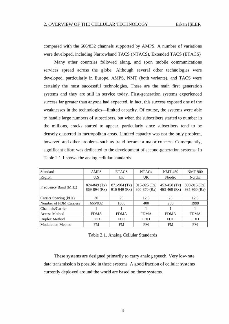
Table 2.1.1 shows the analog cellular standards.
Standard AMPS ETACS NTACs NMT 450 NMT 900 Region U.S UK UK Nordic Nordic
Frequency Band (MHz) 824-849 (Tx)
869-894 (Rx) 871-904 (Tx) 916-949 (Rx)
915-925 (Tx) 860-870 (Rx)
453-458 (Tx) 463-468 (Rx)
890-915 (Tx) 935-960 (Rx)
Carrier Spacing (kHz) 30 25 12,5 25 12,5 Number of FDM Carriers 666/832 1000 400 200 1999 Channels/Carrier 1 1 1 1 1 Access Method FDMA FDMA FDMA FDMA FDMA Duplex Method FDD FDD FDD FDD FDD Modulation Method FM FM FM FM FM
Table 2.1. Analog Cellular Standards
These systems are designed primarily to carry analog speech. Very low-rate
data transmission is possible in these systems. A good fraction of cellular systems
currently deployed around the world are based on these systems.
2. OVERVIEW OF THE CELLULAR TECHNOLOGY Erkan İŞLER
5
2.2. Second Generation Systems
Second generation (2G) mobile systems are digital and bring significant
advantages in terms of service sophistication, capacity and quality according to first
generation systems. The main 2G technologies are GSM (Global System for Mobile
Communication), CDMA (Code Division Multiple Access), D-AMPS (Digital
Advanced Mobile Phone System)
2.2.1. GSM
GSM is one of the 2G technologies. GSM is basically two main parts as SS
(Switching System) and BSS (Base Station System)
SS system contains components of MSC/VLR, HLR, AUC and EIR. BSS
system contains BSC and BTS. In Figure 2.1. shows the GSM system model.

2. OVERVIEW OF THE CELLULAR TECHNOLOGY Erkan İŞLER
6
Figure 2.1. GSM System model
The Switching System is responsible for performing call processing and
subscriber related functions. It includes the following functional units:
Ø MSC - Mobile Services Switching Center
Ø VLR - Visitor Location Register
Ø HLR - Home Location Register
Ø AUC - Authentication Center
Ø EIR - Equipment Identity Register
The Base Station System performs all the radio-related functions. The BSS
includes the following functional units
Ø BTS - Base Transceiver Station
2. OVERVIEW OF THE CELLULAR TECHNOLOGY Erkan İŞLER
7
Ø BSC - Base Station Controller
2.2.1.1. Cell
A cell is the basic unit of a cellular system. Cell is defined as the area of radio
coverage. Each cell is assigned a unique number called Cell Global Identity (CGI). In
Figure 2.2. shows a cell.
Figure 2.2. A Cell
2.2.1.2. MS (Mobile Station)
An MS is used by a mobile subscriber to communicate with the mobile
network. Several types of MSs exist, each allowing the subscriber to make and
receive calls. Different types of MSs have different output power capabilities and
consequently different ranges.
2.2.1.3. SIM (Subscriber Identity Module) Card
In GSM, the subscriber is separated from the mobile terminal. Each
subscriber's information is stored as a "smart card" SIM. The SIM can be plugged
into any GSM mobile terminal. This brings the advantages of security and portability
for subscribers. SIM card contains its unique serial number; it is called IMSI
(International Mobile Subscriber Identity).

2. OVERVIEW OF THE CELLULAR TECHNOLOGY Erkan İŞLER
8
2.2.1.4. BTS
The BTS controls the radio interface to the MS. The BTS comprises the radio
equipment such as transceivers and antennas which are needed to serve each cell in
the network.
2.2.1.5. BSC
A group of BTSs are controlled by a BSC. The BSC manages all the radio-
related functions of a GSM network. It is a high capacity switch that provides
functions such as MS handover, radio channel assignment and the collection of cell
configuration data. In Figure 2.3. shows the BSC and BTS.
Figure 2.3. A BSC and BTS

2. OVERVIEW OF THE CELLULAR TECHNOLOGY Erkan İŞLER
9
2.2.1.6. MSC
A number of BSCs may be controlled by each MSC. The MSC performs the
telephony switching functions for the mobile network. It controls calls to and from
other telephony and data systems, such as the Public Switched Telephone Network
(PSTN), Integrated Services Digital Network (ISDN), public data networks, private
networks and other mobile networks.
2.2.1.7. GMSC
Gateway functionality enables an MSC to interrogate a network's HLR in order
to route a call to a MS. Such an MSC is called a Gateway MSC (GMSC). For
example, if a person connected to the PSTN wants to make a call to a GSM mobile
subscriber, then the PSTN exchange will access the GSM network by first
connecting the call to a GMSC. The same is true of a call from an MS to another MS.
Any MSC in the mobile network can function as a gateway by integration of the
appropriate software.
2.2.1.8. HLR
The HLR is a centralized network database that stores and manages all mobile
subscriptions belonging to a specific operator. It acts as a permanent store for a
person's subscription information until that subscription is canceled. The information
stored includes:
Ø Subscriber identity
Ø Subscriber supplementary services
Ø Subscriber location information
Ø Subscriber authentication information
2. OVERVIEW OF THE CELLULAR TECHNOLOGY Erkan İŞLER
10
The HLR can be implemented in the same network node as the MSC or as a
stand-alone database. If the capacity of the HLR is exceeded, additional HLRs may
be added.
2.2.1.9. VLR
The VLR database contains information about all the mobile subscribers
currently located in an MSC service area. Thus, there is one VLR for each MSC in a
network. The VLR temporarily stores subscription information so that the MSC can
service all the subscribers currently visiting that MSC service area. The VLR can be
regarded as a distributed HLR as it holds a copy of the HLR information stored about
the subscriber. When a subscriber roams into a new MSC service area, the VLR
connected to that MSC requests information about the subscriber from the
subscriber's HLR. The HLR sends a copy of the information to the VLR and updates
its own location information. When the subscriber makes a call, the VLR will already
have the information required for call set-up.
2.2.1.10. EIR
EIR is a database containing mobile equipment identity information. A
common usage of the EIR is with stolen cell phones. Once a user reports to the
operator about the theft, the cell phone's IMEI number goes to EIR, supposedly
making the device unusable in any network.
2.2.1.11. AUC
The main function of the AUC is to authenticate the subscribers attempting to
use a network. In this way, it is used to protect network operators against fraud. The
AUC is a database connected to the HLR which provides it with the authentication
parameters and ciphering keys used to ensure network security.
2. OVERVIEW OF THE CELLULAR TECHNOLOGY Erkan İŞLER
11
2.2.1.12. Modulation Method for GSM
The modulation technique used in GSM is Gaussian Minimum Shift Keying
(GMSK) and is a form of phase modulation, or ‘phase shift keying’ as it is called.
GMSK enables the transmission of 270kbit/s within a 200 kHz channel. This gives a
bit rate of 1.3 bit/s per Hz. This is a rather low bit rate but acceptable as GMSK gives
high interference resistance level. GMSK offers more tolerance of interference.
2.2.1.13. Data Services for GSM
GPRS (General Packet Radio Service) and EDGE (Enhanced Data Rates for
Global Evolution) are data services for GSM.
2.2.1.13.1 GPRS
GPRS is a nonvoice, i.e. data, value added service to the GSM network. This is
done by overlaying a packet based air interface on the existing circuit switched GSM
network. In infrastructure terms, the operator just needs to add a couple of nodes and
some software changes to upgrade the existing voice GSM system to voice plus data
GPRS system. The voice traffic is circuit switched while data traffic is packet
switched. Packet switching enables the resources to be used only when the subscriber
is actually sending and receiving the data. This enables the radio resources to be used
concurrently while being shared between multiple users. The amount of data that can
be transferred is dependent upon the number of users. Theoretical maximum speeds
of up to 171.2 kbps are achievable with GPRS using all eight timeslots at the same
time. GPRS allows the interconnection between the network and the Internet. As
there are the same protocols, the GPRS network can be viewed as a subnetwork of
the Internet, with GPRS capable mobile phones being viewed as mobile hosts.
However, there are some limitations in the GPRS network, such as low speed
(practical speed is much lower than theoretical speeds).

2. OVERVIEW OF THE CELLULAR TECHNOLOGY Erkan İŞLER
12
2.2.1.13.2 EDGE
The limitation of the GPRS network was eliminated to a certain extent by the
introduction of the EDGE technology. EDGE works on TDMA (Time Division
Multiple Access) and GSM systems. It is considered to be a subset of the GPRS as it
can be installed on any system that has GPRS deployed on it. It is not an alternative
to UMTS but a complimentary technology for it. In EDGE with the data rates going
up to 500 kbps (theoretically). However, the major advantage is that existing GSM
networks can be upgraded for the same. Though, not many changes in the hardware
are required by EDGE, except for some hardware upgrades in the BTS and some
software upgraded in the network. However, the second generation system lacked
capacity, global roaming and quality, not to mention the amount of data that could be
sent. This all led to the industry working on a system that had more global reach.
This was the beginning of the evolution of third generation systems.
2.2.2. CDMA
CDMA is also known TIA-EIA-95 or IS-95. IS-95 (Interim Standard 95) is the
first CDMA based digital cellular standard. cdmaone is brand name of IS-95. In
CDMA, users share the same frequency and user can be distinguished each other by
codes.
2.2.3. D-AMPS
It is also known as US-TDMA. D-AMPS uses TDMA as radio access
technique. D-AMPS provides smooth transition between digital and analog systems
in the same area by using existing AMPS channels. In D-AMPS, each 30 kHz
channel pair divided into three time slots and compressed the voice data by digitally,
by this way voice capacity was increased three times.
2. OVERVIEW OF THE CELLULAR TECHNOLOGY Erkan İŞLER
13
2.3. Third Generation Systems
The third generation cellular networks were developed with the aim of offering
high speed data and multimedia connectivity to subscribers. The International
Telecommunication Union (ITU) under the initiative International Mobile
Telecommunications-2000 (IMT-2000) has defined 3G systems as being capable of
supporting high speed data ranges of 144 kbps to greater than 2 Mbps. A few
technologies are able to fulfill the International Mobile Telecommunications (IMT)
standards, such as CDMA, UMTS and some variation of GSM.
2.3.1. CDMA2000
CDMA2000 specification was developed by the Third Generation Partnership
Project 2 (3GPP2), a partnership consisting of five telecommunications standards
bodies: ARIB and TTC in Japan, CWTS in China, TTA in Korea and TIA in North
America. CDMA2000 has already been implemented to several networks as an
evolutionary step from CDMAOne as CDMA2000 provides full backward
compatibility with IS-95B. CDMA2000 is not constrained to only the IMT-2000
band, but operators can also overlay CDMA2000 1x system, which supports 144
kbps now and data rates up to 307 kbps in the future, on top of their existing
CDMAOne network.
CDMA2000 1x EV-DO and CDMA2000 3x are an ITU-approved, IMT-2000
(3G) standards. Cdma2000 3x is part of what the ITU has termed IMT-2000 CDMA
MC (Multi Carrier). It uses less that 5 MHz spectrum (3x 1.25 MHz channels) to
give speeds of over 2 Mbps. CDMA2000 1x with lower data speed is considered to
be a 2.5G technology.
2. OVERVIEW OF THE CELLULAR TECHNOLOGY Erkan İŞLER
14
2.3.2. UMTS (Universal Mobile Telecommunications System)
UMTS is one of the 3G mobile phone technologies. It uses WCDMA as the
underlying standard. WCDMA is the radio access technique for UMTS. WCDMA
was developed by NTTDoCoMo as the air interface for their 3G network Freedom of
Mobile Multimedia Access (FOMA). Later it submitted the specification to the
International Telecommunication Union (ITU) as a candidate for the international 3G
standard known as IMT-2000. The ITU eventually accepted WCDMA as part of the
IMT-2000 family of 3G standards. Later, WCDMA was selected as the air interface
for UMTS, the 3G successor to GSM. Some of the key features include the support
to two basic modes Frequency-Division Duplexing (FDD) and Time-Division
Duplexing (TDD), variable transmission rates, inter cell asynchronous operation,
adaptive power control, increased coverage and capacity, etc. WCDMA also uses the
CDMA multiplexing technique, due to its advantages over other multiple access
techniques such as TDMA. WCDMA is merely the air interface as per the definition
of IMT-2000, while UMTS is a complete stack of communication protocols
designated for 3G global mobile telecommunications. UMTS uses a pair of 5 MHz
channels, one in the 1900 MHz range for uplink and one in the 2100 MHz range for
downlink. The specific frequency bands originally defined by the UMTS standard
are 1885–2025 MHz for uplink and 2110–2200 MHz for downlink.
2.3.2.1. UMTS System Architecture
UMTS network consists of three interacting domains: Core Network (CN),
UMTS Terrestrial Radio Access Network (UTRAN) and User Equipment (UE).
The UE contains the mobile phone and the SIM (Subscriber Identity Module)
card called USIM (Universal SIM). USIM contains member specific data and
enables the authenticated entry of the subscriber into the network. This UMTS UE is
capable of working in three modes: CS (circuit switched) mode, PS (packet
switched) mode and CS/PS mode. In the CS mode the UE is connected only to the

2. OVERVIEW OF THE CELLULAR TECHNOLOGY Erkan İŞLER
15
core network. In the PS mode, the UE is connected only to the PS domain (though
CS services like VoIP (Voice over Internet Protocol) can still be offered), while in
the CS/PS mode, the mobile is capable of working simultaneously to offer both CS
and PS services. The components of the Radio Access Network (RAN) are the BS or
Node B and Radio Network Controllers (RNCs). The major functions of the BS are
closed loop power control, physical channel coding, modulation/demodulation, air
interface transmissions/reception, error handling, etc., while major functions of the
RNC are radio resource control/management, power control, channel allocation,
admission control, ciphering, segmentation/reassembly, etc. The main function of the
Core Network (CN) is to provide switching, routing and transit for user traffic. The
CN also contains the databases and network management functions. The basic CN
architecture for UMTS is based on the GSM network with GPRS. All equipment has
to be modified for UMTS operation and services. The CN is divided into the CS and
PS domains. Circuit switched elements are the Mobile Services Switching Centre
(MSC), Visitor Location Register (VLR) and Gateway MSC. Packet switched
elements are the Serving GPRS Support Node (SGSN) and the Gateway GPRS
Support Node (GGSN). Network elements like EIR, HLR, VLR and AUC are shared
by both domains. The Asynchronous Transfer Mode (ATM) is defined for UMTS
core transmission. The ATM Adaptation Layer type 2 (AAL2) handles the circuit
switched connection and the packet connection protocol AAL5 is designed for data
delivery.
2.3.2.2. Data Services for UMTS
Release ’99 is the first data service for UMTS. Release ’99 is also known as
R99. Theoretical maximum speed of R99 is 384 kbps.
HSDPA (High Speed Downlink Packet Access) was introduced in 3GPP
Release 5. The aim of HSDPA is to increase downlink packet data throughput.
HSDPA support 1.8, 3.6, 7.2 and 14.0 Mbit/s downlink data throughput.

2. OVERVIEW OF THE CELLULAR TECHNOLOGY Erkan İŞLER
16
2.4. Fourth Generation Systems
Next step in the evolution of broadband systems called the fourth-generation
systems. The infrastructure for 4G will be only packet-based (all-IP). A number of
the so called 4G technologies are in fact actually evolutions of 3G technologies, e.g.
Long Term Evolution (LTE) from 3GPP and Ultra Mobile Broadband (UMB) from
3GPP2. One of the drivers for the popular use of 4G has been the aggressive
promotion within the industry of the IEEE 802.16e (WiMax) mobile standard. A
version of this standard was, however, recently accepted by the ITU as an addition to
the IMT-2000 family and therefore is clearly to be considered together with the other
3G IMT-2000 technologies. The ITU is studying future broadband mobile
capabilities under the name IMTAdvanced, which the ITU has recently defined as
the fourth generation (4G) of mobile technologies.
The generic designation IMT is now used by the ITU in the Radio Regulations,
as revised at WRC-07, to identify potential spectrum for Administrations wishing to
implement IMT-2000 (3G) or IMT-Advanced (4G). The recently ITU World Radio
Conference (WRC-07) identified significant additional spectrum below 1 GHz, as
well as additional bands above 2GHz, for potential IMT use. IMT-2000 3G wireless
technologies clearly have significant future development potential, much as 2G
technologies have already done, and it seems only reasonable to allow these 3G
technologies to fully develop before phasing in a fourth mobile generation.
2.4.1. UMB
Ultra Mobile Broadband (UMB) is one of the fourth generation mobile phone
technologies. UMB was the brand name for a project within 3GPP2 to improve the
CDMA2000 mobile phone standard for next generation applications and
requirements. 3GPP2’s convergence to UMB follows an evolutionary path in the
family of CDMA2000 standards. UMB is therefore a candidate for existing or new
spectrum allocations with its scalable bandwidth feature up to 20 MHz. OFDMA is

2. OVERVIEW OF THE CELLULAR TECHNOLOGY Erkan İŞLER
17
the radio access technique for UMB. UMB integrates advanced radio access
techniques into a single global standard in order to fulfill 4G requirements for
3GPP2. UMB is based on a flat All-IP network architecture, called Converged
Access Network (CAN).
Network Controller (SRNC), evolved Base Station (eBS), and Access Terminal
(AT). Access Gateway (AGW) is responsible of maintaining the data path
functionality. It is the anchor mobility point for mobility within AGW domain and
assists Home Agent (HA) for mobility across AGW domains. SRNC is responsible
for facilitating control signaling. eBS implements UMB air interface like AT and
maintains the over-the-air communication with AT. eBS also performs QoS
classification, admission control, and scheduling.
UMB air interface offers flexible and scalable bandwidth supports from 1.25 to
20MHz in steps of 154 KHz. FDD/TDD modes are supported and TDD
standardization is in progress. UMB FDD is proposed as FDD mode of IEEE 802.20
(Mobile Wireless Broadband Access) standard. It is designed for full frequency reuse
that does not need frequency planning. Resource allocation offers low latency and
introduces persistent and nonpersistent allocation. The UMB control mechanisms
optimize the transmission of variable length packets for each application based on
the QoS requirements of each application and user.
2.4.2. WiMax
The underlying technology of WiMAX (Worldwide Interoperability for
Microwave Access), also known as IEEE 802.16, is considered to be a 4G system but
early evolution and adoption of WiMAX has led the IEEE and the WiMAX Forum to
ask R-ITU (Radiocommunication sector of the International Telecommunication
Union) to include mobile WiMAX based on 802.16e into its IMT20005 specification
(International Mobile Telecommunications 2000). WiMAX is included in IMT2000
in October 2007, which was originally created to harmonize 3G mobile systems.
OFDMA is the radio access technique for WiMAX. WiMAX uses frequency bands

2. OVERVIEW OF THE CELLULAR TECHNOLOGY Erkan İŞLER
18
of 10-66 GHz, covering long geographical areas using licensed or unlicensed
spectrum.
2.4.3. LTE
Long Term Evolution (LTE) describes standardization work by the Third
Generation Partnership Project (3GPP) to define a new high-speed radio access
method for mobile communications systems. LTE is the next step on a clearly-
charted roadmap to so-called ‘4G’ mobile systems
LTE (Long Term Evolution) is one of the fourth generation technologies. LTE
offers several important benefits for consumers and operators:
• Performance and Capacity: One of the requirements on LTE is to provide
downlink peak rates of at least 100Mbit/s
• Simplicity: First, LTE supports flexible carrier bandwidths, from below
5MHz up to 20MHz. LTE also supports both FDD (Frequency Division
Duplex) and TDD (Time Division Duplex). Ten paired and four unpaired
spectrum bands have so far been identified by 3GPP for LTE. And there are
more bands to come. This means that an operator may introduce LTE in
‘new’ bands where it is easiest to deploy 10MHz or 20MHz carriers, and
eventually deploy LTE in all bands. Second, LTE radio network products will
have a number of features that simplify the building and management of next-
generation networks. For example, features like plug-and-play, self-
configuration and self-optimization will simplify and reduce the cost of
network roll-out and management.
Third, LTE will be deployed in parallel with simplified, IP-based core and
transport networks that are easier to build, maintain and introduce services
on.
• Wide range of terminals – in addition to mobile phones, many computer and
consumer electronic devices, such as notebooks, ultra-portables, gaming
devices and cameras, will incorporate LTE embedded modules.

2. OVERVIEW OF THE CELLULAR TECHNOLOGY Erkan İŞLER
19
LTE uses Orthogonal Frequency Division Multiple Access (OFDMA) in
downlink and Single Carrier Frequency Division Multiple Access (SC-FDMA) in
uplink. These multiple access solutions provide orthogonality between the users,
reducing the interference and improving the network capacity. The resource
allocation in the frequency domain takes place with a resolution of 180 kHz resource
blocks both in uplink and in downlink. The frequency dimension in the packet
scheduling is one reason for the high LTE capacity. The multiple access schemes are
illustrated in Figure 2.4.
Figure 2.4. LTE Multiple Access Schemes (HOLMA, H, TOSKALA, A, 2009)
LTE’s transition to a ‘flat’, all-IP based core network with a simplified
architecture and open interfaces. Indeed, much of 3GPP’s standardisation work
targets the conversion of existing core network architecture to an all-IP system.
Within 3GPP, this initiative has been referred to as Systems Architecture Evolution
(SAE) – now called Evolved Packet Core (EPC). SAE/EPC enables more flexible
service provisioning plus simplified interworking with fixed and non-3GPP mobile
networks.
A number of companies have already demonstrated various elements at public
events. With 3GPP Release 8 now being consolidated (3GPP has recently approved
the LTE specifications – they are now under change control and will be completed

2. OVERVIEW OF THE CELLULAR TECHNOLOGY Erkan İŞLER
20
by the end of 2008), many industry players and observers anticipate the commercial
launch of the first LTE networks and terminal devices in around 2010. To make this
objective possible, LTE technology will have matured through field trials performed
in 2008 and pre-commercial networks with friendly users in 2009. There is
widespread industry consensus that operator-retained revenues from LTE will
gradually replace those generated by WCDMA and HSPA. By way of example, a
study by ABI Research suggests that LTE will dominate the world's mobile
infrastructure markets after 2011.
Figure 2.5. Evolution Time Frame for Planned 3GPP Systems
3. UMTS Erkan İŞLER
21
3. UMTS
3.1. Introduction
Universal Mobile Telecommunications System (UMTS) is one of third
generation (3G) technologies. Release99 (R99) architecture is the first deployment of
UMTS. UMTS is specified by 3GPP (3rd Generation Partnership Project). 3GPP is
collaboration between groups of telecommunications associations, to satisfy a
globally applicable 3G mobile phone system specifications.
3.2. Architecture of UMTS Network
The development in 3G networks is based on the evolution of GSM/GPRS
networks.3G Networks support all types of services such like data, video and voice
conversations. Internet Protocol (IP) is introduced as a driving technology. GPRS
presented IP backbone into mobile core network. UMTS introduced a new radio
access technology which is totally based on radio access network without bringing
any change into the core network. After implementation of successive releases of
UMTS, a major change such as Internet Protocol (IP) is introduced in core network
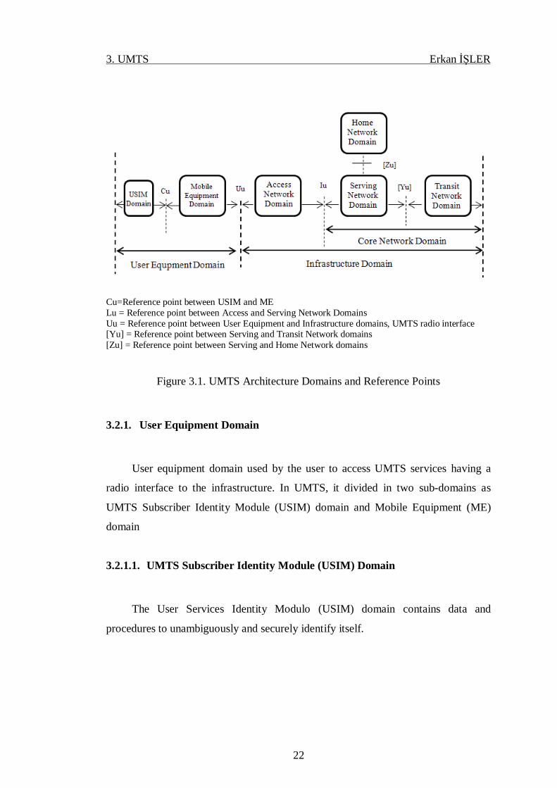
The generic architecture of UMTS physically consists of two main domains, i.e. the
user equipment (UE) domain and the infrastructure domain. Figure 3.1. illustrates the
different UMTS domains. The domains and sub-domains are described as below.
3. UMTS Erkan İŞLER
22
Cu=Reference point between USIM and ME Lu = Reference point between Access and Serving Network Domains Uu = Reference point between User Equipment and Infrastructure domains, UMTS radio interface [Yu] = Reference point between Serving and Transit Network domains [Zu] = Reference point between Serving and Home Network domains
Figure 3.1. UMTS Architecture Domains and Reference Points
3.2.1. User Equipment Domain
User equipment domain used by the user to access UMTS services having a
radio interface to the infrastructure. In UMTS, it divided in two sub-domains as
UMTS Subscriber Identity Module (USIM) domain and Mobile Equipment (ME)
domain
3.2.1.1. UMTS Subscriber Identity Module (USIM) Domain
The User Services Identity Modulo (USIM) domain contains data and
procedures to unambiguously and securely identify itself.
3. UMTS Erkan İŞLER
23
3.2.1.2. Mobile Equipment (ME) Domain
Mobile equipment domain consists of: The mobile termination (MT) and
terminal equipment (TE). The mobile termination entity performing the radio
transmission and related functions, and the terminal equipment entity containing the
end-to-end application, (e.g. a laptop connected to a handset). Both entities are
physically situated in same card.
3.2.2. Infrastructure Domain
Infrastructure domain consists of the physical nodes, which perform the various
functions required to terminate the radio interface and to support the
telecommunication services requirements of the users. Infrastructure domain is
categorized in two parts i.e. Access Network (AN) and Core Network (CN)
3.2.2.1. Access Network (AN) Domain
Consists of the physical entities managing the access network resources and
provides the users with mechanisms to access the core network.
3.2.2.2. Core Network (CN) Domain
Consists of the physical entities providing support for the network features and
telecommunication services; e.g. management of user location information, control
of network features and services, switching and transmission mechanisms for
signaling and for user generated information. Core network has three different sub
domains characterized in different situations where users communicate with each
other in different types of network like fixed or mobile network.

3. UMTS Erkan İŞLER
24
3.2.2.2.1 Home Network (HN) Domain
Home Network (HN) domain representing the core functions conducted at a
permanent location regardless of the user’s access point. The USIM is related by
subscription to the HN.
3.2.2.2.2 Service Network (SN) Domain
Serving Network (SN) domain representing the core network functions local to
the user’s access point and thus their location changes when the user moves
3.2.2.2.3 Transit Network (TN) Domain
Transit Network (TN) domain, which is the CN part between the SN and the
remote party.
3.3. Universal Terrestrial Radio Access Network (UTRAN)
Functionally the network elements are grouped into the Radio Access Network
(RAN,UMTS Terrestrial RAN = UTRAN) that handles all radio-related
functionality, and the Core Network, which is responsible for switching and routing
calls and data connections to external networks. It establishes a connection between
user equipment (UE) and core network (CN). To complete the system, the User
Equipment that interfaces with the user and the radio interface is defined. The high-
level system architecture is shown in Figure 3.2.
From a specification and standardization point of view, both UE and UTRAN
consist of completely new protocols, the design of which is based on the needs of the
new WCDMA radio technology. On the contrary, the definition of Core Network
(CN) is adopted from GSM. This gives the system with new radio technology a
global base of known and rugged CN technology that accelerates and facilitates its
introduction, and enables such competitive advantages as global roaming.

3. UMTS Erkan İŞLER
25
Figure 3.2. UMTS high-level system architecture
UTRAN consists of one or more Radio Network Sub-systems (RNS). An RNS is a
subnetwork within UTRAN and consists of one Radio Network Controller (RNC)
and one or more Node Bs. RNCs may be connected to each other via an Iur interface.
RNCs and Node Bs are connected with an Iub interface as shown in Figure 3.3.

3. UMTS Erkan İŞLER
26
Figure 3.3. UTRAN Architecture
UTRAN network elements are described as below.

3. UMTS Erkan İŞLER
27
3.3.1. Radio Network Sub-systems (RNS)
An RNS is a subnetwork within UTRAN and consists of one Radio Network
Controller (RNC) and one or more Node Bs. RNS is responsible to receive and
deliver the information.
3.3.2. The Radio Network Controller (RNC)
The RNC is the network element responsible for the control of the radio
resources of UTRAN. It interfaces the CN and also terminates the RRC (Radio
Resource Control) protocol that defines the messages and procedures between the
mobile and UTRAN. It logically corresponds to the GSM BSC.
RNC performs several logical functions as below.
• Controlling RNC (CRNC): The Controlling RNC is responsible for the load and
congestion control of its own cells, and also executes the admission control and code
allocation for new radio links to be established in those cells.
• Serving RNC (SRNC): The SRNC also terminates the radio resource control
signaling. Basic radio resource management operations, such as the mapping of
Radio Access Bearer parameters into air interface transport channel parameters, the
handover decision, and outer loop power control, are executed in the SRNC.
• Drift RNC (DRNC): The DRNC is any RNC, other than the SRNC, that controls
cells used by the mobile. If needed, the DRNC may perform macrodiversity
combining and splitting.
One physical RNC normally contains all the CRNC, SRNC and DRNC
functionality.

3. UMTS Erkan İŞLER
28
3.3.3. The Node B (Base Station)
The main function of the Node B is to perform the air interface processing
(channel coding and interleaving, rate adaptation, spreading, etc.). It also performs
some basic Radio Resource Management operations such as the inner loop power
control. It logically corresponds to the GSM Base Station.
3.4. UMTS Core Network Architecture and Evolution Core Network
While the UMTS radio interface, WCDMA, represented a bigger step in the
radio access evolution from GSM networks, the UMTS core network did not
experience major changes in the 3GPP Release ’99 specification. The Release ’99
structure was inherited from the GSM core network and, as stated earlier, both
UTRAN and GERAN based radio access network connect to the same core network.
The Release 5 core network has many additions compared to Release ’99 core
networks. Release 4 already included the change in core network CS domain when
the MSC was divided into MSC server and Media Gateway (MGW). Also, the
GMSC was divided into GMSC server and MGW. Release 5 contains the first phase
of IP Multimedia Sub-system (IMS), which will enable a standardised approach for
IP-based service provision via PS domain.
3.4.1. Release ’99 Core Network Elements
The Release ’99 core network has two domains: Circuit Switched (CS) domain
and Packet Switched (PS) domain, to cover the need for different traffic types
Figure 3.4. illustrates the Release ’99 UMTS core network structure both CS and PS
domains shown.

3. UMTS Erkan İŞLER
29
Figure 3.4. Release ’99 UMTS core network structure (HOLMA, H, TOSKALA, A,
2007)
3.4.1.1. The CS Domain
The CS domain has the following elements, Mobile switching center (MSC),
Gateway MSC (GMSC), home location register (HLR), visitor location
register(VLR) And Service Control Point (SCP).
• Mobile Switching Centre (MSC): MSC can actually be defined as a central
signaling and switching functions performing unit in UMTS. Iu CS interface
is used by the MSC for the interaction with RAN. Also, CS services are
provided or handled by the MSC. The additional feature of MSC in UMTS is
its capability and capacity of managing handovers and other mobility related
functionalities like position registering procedures.
• Gateway MSC (GMSC): Basically it is a particular MSC that offers CS
services between core network and external network and also responsible for
all incoming / outgoing calls to the external network.

3. UMTS Erkan İŞLER
30
• Home Location Register (HLR): The information of the subscribers is
contained by the HLR for a particular network. It also includes the service
profiles. Its core responsibility is the management of mobile users.
• Visitor Location Register (VLR): VLR is responsible to manage the roaming
of MS within the boundary of MSC. VLR has particular location information
regarding the users. On many occasions it accomplishes specific tasks
without any interaction with HLR. If mobile users enter in any new region of
MSC then the area which cover the MSC, sends a notice for registry and then
transfer to VLR, where a mobile station is placed. Meanwhile if MS is not
able to register, the VLR and HLR share their information to accept the new
call
• Service Control Point (SCP): SCP is responsible to indicate the link for
providing a particular service to the end user.
3.4.1.2. The PS Domain
The PS domain has the following elements, Serving GPRS Support Node
(SGSN) and Gateway GPRS Support Node (GGSN).
• Serving GPRS Support Node (SGSN): SGSN covers similar functions as the
MSC for the packet data, including VLR type functionality. SGSN is
responsible for three main functions which are security task, access control
and mobility management.
• Gateway GPRS Support Node (GGSN): GGSN connects PS core network to
other networks, for example to the Internet.
3.4.2. Release 5 Core Network and IP Multimedia Sub-system
The Release 5 core network has many additions compared to Release ’99 core
networks. Release 4 already included the change in core network CS domain when
the MSC was divided into MSC server and Media Gateway (MGW). Also, the
3. UMTS Erkan İŞLER
31
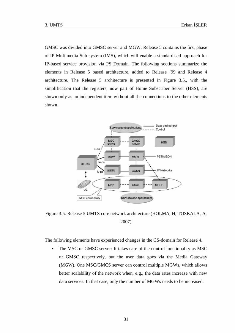
GMSC was divided into GMSC server and MGW. Release 5 contains the first phase
of IP Multimedia Sub-system (IMS), which will enable a standardised approach for
IP-based service provision via PS Domain. The following sections summarize the
elements in Release 5 based architecture, added to Release ’99 and Release 4
architecture. The Release 5 architecture is presented in Figure 3.5., with the
simplification that the registers, now part of Home Subscriber Server (HSS), are
shown only as an independent item without all the connections to the other elements
shown.
Figure 3.5. Release 5 UMTS core network architecture (HOLMA, H, TOSKALA, A,
2007)
The following elements have experienced changes in the CS-domain for Release 4.
• The MSC or GMSC server: It takes care of the control functionality as MSC
or GMSC respectively, but the user data goes via the Media Gateway
(MGW). One MSC/GMCS server can control multiple MGWs, which allows
better scalability of the network when, e.g., the data rates increase with new
data services. In that case, only the number of MGWs needs to be increased.

3. UMTS Erkan İŞLER
32
• MGW: It performs the actual switching for user data and network
interworking processing, e.g., echo cancellation or speech
decoding/encoding.
In the PS-domain, the SGSN and GGSN are as in Release ’99 with some
enhancements, but for the IP-based service delivery, the IMS has now the following
key elements included:
• Media Resource Function (MRF): MRF controls media stream resources or
can mix different media streams. The standard defines further the detailed
functional split for MRF.
• Call Session Control Function (CSCF): CSCF acts as the first contact point to
the terminal in the IMS (as a proxy). The CSCF covers several functionalities
from handling of the session states to being a contact point for all IMS
connections intended for a single user and acting as a firewall towards other
operator’s networks.
• Media Gateway Control Function (MGCF): MGCF is responsible to handle
protocol conversions. This may also control a service coming via the CS
domain and perform processing in an MGW, e.g. for echo cancellation.
3.5. UMTS Radio Interface Protocols
The Radio Access Network is divided into a user plane and a control plane.
The user plane is used for sending user data while the control plane is used for
signaling. UMTS radio interface protocol architecture presented in Figure 3.6. It can
be seen how the three layers (L1, L2, and L3) are connected using logical, transport
and physical channels.
3. UMTS Erkan İŞLER
33
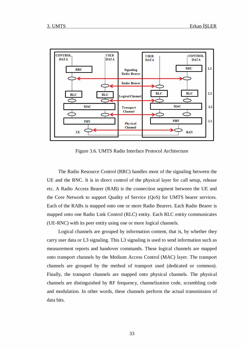
Figure 3.6. UMTS Radio Interface Protocol Architecture
The Radio Resource Control (RRC) handles most of the signaling between the
UE and the RNC. It is in direct control of the physical layer for call setup, release
etc. A Radio Access Bearer (RAB) is the connection segment between the UE and
the Core Network to support Quality of Service (QoS) for UMTS bearer services.
Each of the RABs is mapped onto one or more Radio Bearers. Each Radio Bearer is
mapped onto one Radio Link Control (RLC) entity. Each RLC entity communicates
(UE-RNC) with its peer entity using one or more logical channels.
Logical channels are grouped by information content, that is, by whether they
carry user data or L3 signaling. This L3 signaling is used to send information such as
measurement reports and handover commands. These logical channels are mapped
onto transport channels by the Medium Access Control (MAC) layer. The transport
channels are grouped by the method of transport used (dedicated or common).
Finally, the transport channels are mapped onto physical channels. The physical
channels are distinguished by RF frequency, channelization code, scrambling code
and modulation. In other words, these channels perform the actual transmission of
data bits.

3. UMTS Erkan İŞLER
34
3.5.1. Logical Channels
Logical channel types are classified into two groups: Control channels and
Traffic channels.
3.5.1.1. Control Channels
Control channels for the transfer of control information
• The Broadcast Control Channel (BCCH): BCCH is a downlink channel for
broadcasting system information.
• Paging Control Channel (PCCH): PCCH is a downlink channel that transfers
paging information and is used when the UE is in idle mode.
• The Common Control Channel (CCCH): CCCH is a bi-directional channel
that transfers control information between the network and UE. This channel
is used by the UE needs to access the network
• The Dedicated Control Channel (DCCH): DCCH is a point-to-point bi-
directional channel that transmits dedicated control information between UE
and the network. This channel is established through a RRC connection setup
procedure.
3.5.1.2. Traffic Channels
Traffic channels for the transfer of user information.
• The Dedicated Traffic Channel (DTCH): DTCH is a point-to-point channel,
dedicated to one UE, for transferring user information. A DTCH can exist in
the uplink and downlink.
• Common Traffic Channel (CTCH): CTCH is a point-to-multipoint downlink
channel for transfer of dedicated user information for all, or a group of
specified, UEs.

3. UMTS Erkan İŞLER
35
3.5.2. Transport Channels
Transport channels are defined between MAC and physical layer. A transport
channel is defined by how, and with what characteristics, data is transferred over the
air interface. There are two types of transport channels: Common channels and
dedicated channels. There is only one dedicated transport channel and the remaining
six are common.
3.5.2.1. Dedicated Channels
• Dedicated Channel (DCH): DCH is used in both downlink and uplink. The
DCH transmits user or control information in either direction
3.5.2.2. Common Channels
• Broadcast Channel (BCH): BCH is used in downlink (DL) direction. BCH
transmits system- and cell-specific information
• Common Packet Channel (CPCH): CPCH transports packet-based user data
in uplink (UL) direction
• Downlink Shared Channel (DSCH): DSCH is used in downlink direction. It
Shared by several UEs; carries user and control information
• Forward-Access Channel (FACH): FACH is used in downlink direction. It
transports control information to the UE
• Paging channel (PCH): PCH is used in downlink direction. It Used to page
information to the UE
• Random-access channel (RACH): RACH is used in uplink direction. It
Received from complete cell and contains control information from the UE
3. UMTS Erkan İŞLER
36
3.5.3. Physical Channels
There are two types of physical channel: dedicated and common. Physical
channels are a layered structure of radio frames and time slots carrying information
related to the physical layers. The physical channels are identified by a specific
carrier frequency, codes (channelization/ scrambling), timings, etc. There are two
dedicated channels and five common channels.
3.5.3.1. Dedicated Channels
• Dedicated Physical Control Channel (DPCCH): DPCCH is used in both
downlink and uplink. It dedicated higher link information such as user data
and signalling is carried on this layer
• Dedicated Physical Data Channel (DPDCH): DPDCH is used in both
downlink and uplink. It transmits dedicated physical-layer control
information
3.5.3.2. Common Channels
• Physical Random-Access Channel (PRACH): PRACH is used in uplink. It
transmits the data part of RACH and layer 1 control information
• Physical Common Packet Channel (PCPCH): PCPCH is used in uplink. It
carries CPCH transport channel
• Physical Downlink Shared Channel (PDSCH): PDSCH is used in downlink.
It carries DSCH transport channel
• Primary Common Control Physical Channel (PCCPCH): PCCPCH is used in
downlink. It carries BCH transport channel and contains only data
• Secondary Common Control Physical Channel (SCCPCH): SCCPCH is used
in downlink. It carries FACH and PCH transport channels

3. UMTS Erkan İŞLER
37
In the Figure 3.7. all the channel mapping is illustrated.
Figure 3.7. UMTS Channel Mapping
3.6. Physical Layer
The physical layer of the radio interface has been typically the main discussion
topic when different cellular systems have been compared against each other. The
physical layer structures naturally relate directly to the achievable performance
issues when observing a single link between a terminal station and a base station. For

3. UMTS Erkan İŞLER
38
the overall system performance the protocols in the other layers, such as handover
protocols, also have a great deal of impact. Naturally it is essential to have low
Signal-to-Interference Ratio (SIR) requirements for sufficient link performance with
various coding and diversity solutions in the physical layer, since the physical layer
defines the fundamental capacity limits.
In the physical layer of UMTS, WCDMA is adopted as a radio access
technology. The basic role of physical layer is to transform the data information into
radio signals (physical) which have been received from different transport channels.
Procedures of different types are performed in the physical layer in order to produce
the radio signals to be sent to the antennas for transmission from the received
transport block. Whereas the reveres process is carried out for theses radio signals at
the receiver end to recover the transport block and farther transported to the MAC
layer. A number of key functions are performed by the physical layer in UMTS
/WCDMA.
It has to carry out and handover procedures , detection of error , channel
multiplexing , mapping of transport channels to physical channels, power control,
synchronization of frequency and time and a number of other functionalities
regarding transmission and reception of the radio (physical) signals are also executed
in the physical layer in addition to the above tasks. Now we shall discuss some
important characteristic features and functionalities to be covered by radio (physical)
layer. A special type of modulation system where spread spectrum (modulated)
signal bandwidth is larger than the actual signal bandwidth. This spectral spreading is
completed through a code which is free from the information signal and also this
code is again reused at receiver end to dispread the signal.
3.6.1. Cell Structure
UMTS can offer different coverage-scales to different users. There are in total
four different UMTS hierarchical cell structures, which are pico-cell, micro-cell,
macro-cell and global cell.

3. UMTS Erkan İŞLER
39
• Pico Cell: It covers only a small area such as one office room
• Micro Cell: It can cover a vicinity of several buildings to provide local
UMTS services
• Macro Cell: It will span an area as large as a few kilometers in radius as a
regional service provider.
• Global Cell: It will be covered by satellites and will be available to any place
around the world.
Under such a hierarchical cell structure, UMTS can provide services to users
located in various geographical regions on the earth. It is to be noted that formation
of a global cell needs to use other technology rather than UTRAN due to the nature
of the long propagation delay in a satellite air-link sector.
Figure 3.8. shows a conceptual diagram of the UMTS hierarchical cell structure
(HCS), which include all four different cells.
Figure 3.8. UMTS Hierarchical Cell Structure (CHEN, H, 2007)
3.6.2. Power Control
Power control is necessary in any spread spectrum system. In UMTS all users
share the same frequency separated via using of different spreading codes and each
user’s signals acts as random interference to other users. This issue is also known as
3. UMTS Erkan İŞLER
40
the near-far problem in a spread-spectrum multiple access systems, and arises when a
mobile user near a cell jams a user that is distant from the cell (assuming both are
transmitting at the same power). The problem is this: consider a receiver and two
transmitters (one close to the receiver; the other far away). If both transmitters
transmit simultaneously and at equal powers, then the receiver will receive more
power from the nearer transmitter. This makes the farther transmitter more difficult,
if not impossible, to "understand." Since one transmission’s signal is the other’s
noise the signal-to-noise ratio (SNR) for the farther transmitter is much lower. If the
nearer transmitter transmits a signal that is orders of magnitude higher than the
farther transmitter then the SNR for the farther transmitter may be below detect
ability and the farther transmitter may just as well not transmit. This effectively jams
the communication channel. In UMTS this is commonly solved by power control.
Figure 3.9. demonstrates power control mechanism working principle. There are four
UEs located at different distances from base station (BS); if there is no power control
mechanism user D signal reaches the BS with too low power since this user is
located too far from BS and signals from other UEs reject the user D signal.
UMTS defines two main different power control mechanisms:
• Open-loop power control
• Closed-loop power control
3.6.2.1. Open - Loop Power Control
In the UMTS standard, open-loop power control is defined as the ability of the
UE transmitter to set its output power to a specific value. It is used for setting initial
uplink and downlink transmission powers when a UE is accessing the network. The
open loop power control tolerance is ±9 dB (under normal conditions) and ±12 dB
(under extreme conditions).

3. UMTS Erkan İŞLER
41
Figure 3.9. Near-far Problem Example (CHEN, H, 2007)
3.6.2.2. Closed-Loop Power Control
Closed-loop power control has an inner and an outer loop
• Inner - Loop Power Control
In UMTS, inner-loop power control, also called fast closed-loop power control.
[The Next Generation. CDMA Technologies] In the uplink the base station measures
the received Signal-to-Interference Ratio (SIR) and compares this to a target SIR. If
the measured SIR is below the target then the base station requests the mobile to
increase its power (and vice versa). This type of power control is known as the Inner-
loop power control and is capable of adjusting the transmit power in steps of, for
example 1 dB at a rate of 1500 times per second. Inner-loop power control is only
applicable for connections on dedicated channels.
• Outer - Loop Power Control
In UMTS, outer-loop power control, also called slow closed-loop power
control.Outer-loop power control is used to adjust the target SIR in reaction to

3. UMTS Erkan İŞLER
42
changes in the block error ratio (BLER) after decoding. If the BLER increases, then
the target SIR is increased in an attempt to reduce the BLER. This process
continuously changes the target SIR to maintain a minimum acceptable BLER.
Outer-loop power control is only applicable for connections on dedicated channels.
Figure 3.10. gives an overview of the three power control algorithms
Figure 3.10. UMTS Power Control Loops
3.6.3. Capacity and Capacity Management
The capacity of UMTS system is proportional to the processing gain of the
system, which is the ratio of the spread bandwidth to the data rate. A general
expression for the signal-to-noise (SNR) power ratio for a particular mobile user at
the base station given by
Where, S = Eb / Tb=REb is the carrier power and N=BN0 is the interference
power at the base station receiver. The quantity Eb / N0 is the bit energy to noise
3. UMTS Erkan İŞLER
43
power spectral density ratio, and B / R is the processing gain of the system. Let K
denote the number of mobile users. If power control is used to ensure that every
mobile has the same received power, the SNR of one user can be written as
This is so because the total interference power in the band is equal to the sum
of powers from individual users. The capacity for UMTS system is found to be
The capacity of UMTS system is limited by the interference caused by other
users simultaneously occupying the same bandwidth; this interference is reduced by
the processing gain of the system.
Capacity Management aims to control the load in the RAN. The purpose of
Capacity Management is to maximize the capacity in RAN while maintaining the
requested Quality of Services and coverage, and stabilizing the cell carrier behavior
in the air interface. Capacity Management is useful in an overload situation. An
overload situation occurs due to fluctuations in the uplink interference and/or the
used downlink power. These fluctuations are a natural process caused by a number of
factors including fading, intercell interference, and variations in the carried traffic of
the individual connections.
3.6.3.1. Admission Control
The purpose of Admission Control is to selectively deny access request in order
to limit the load, and so avoids excessive triggering of congestion control. Normally
Admission Control is applied at cell level on dedicated radio link setup, addition or
modification where additional resources are required. The resources are a selected
subset of the total resources in the RAN, whose usage is constantly monitored by

3. UMTS Erkan İŞLER
44
Admission Control (Figure 3.11.). In the situations of high load the input for
admission about resources causes Admission Control to block new requests.
Figure 3.11. Admission Control
3.6.3.2. Congestion Control
The purpose of Congestion Control is to solve overload situations. An overload
situation occurs due to, for example, fluctuations in the UL in interference and/or the
used DL power. Congestion Control is applied at cell level and becomes active when
the current cell load exceeds predefined limits. The activation of Congestion Control
results in a set of actions on the admitted services in a cell to reduce the cell load.
Congestion Control reduces the load until it is back to an acceptable level.
3.6.4. Multipath Diversity and Rake Receiver
In a radio link, the RF signal from the transmitter may be reflected from objects
such as hills, buildings, or vehicles. This is known as multipath propagation.
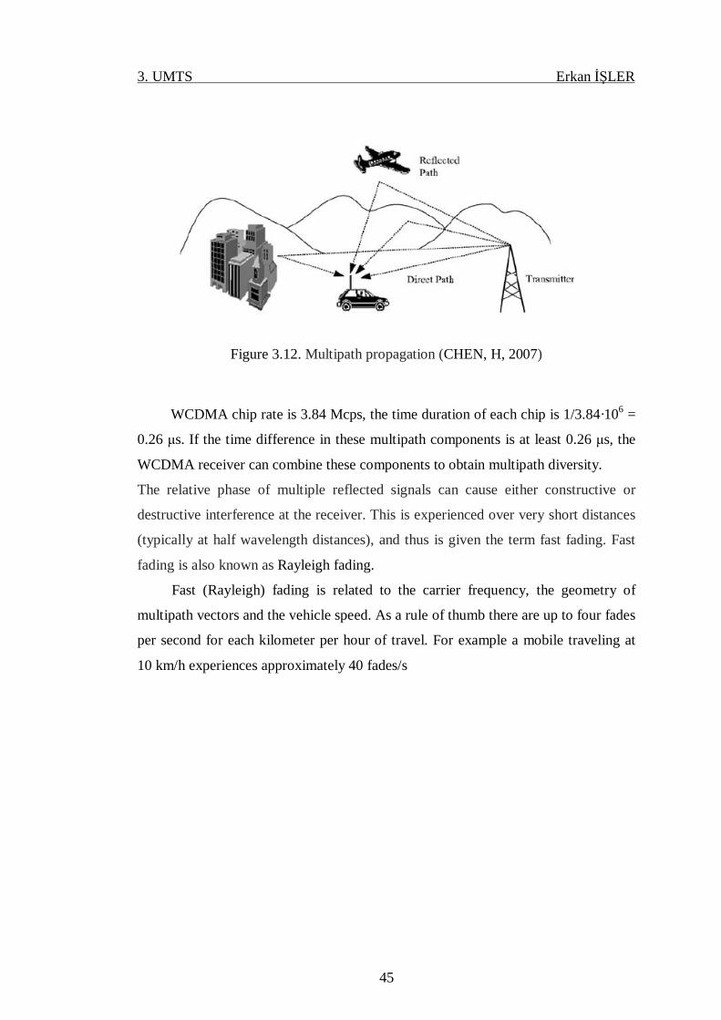
3. UMTS Erkan İŞLER
45
Figure 3.12. Multipath propagation (CHEN, H, 2007)
WCDMA chip rate is 3.84 Mcps, the time duration of each chip is 1/3.84·106 =
0.26 μs. If the time difference in these multipath components is at least 0.26 μs, the
WCDMA receiver can combine these components to obtain multipath diversity.
The relative phase of multiple reflected signals can cause either constructive or
destructive interference at the receiver. This is experienced over very short distances
(typically at half wavelength distances), and thus is given the term fast fading. Fast
fading is also known as Rayleigh fading.
Fast (Rayleigh) fading is related to the carrier frequency, the geometry of
multipath vectors and the vehicle speed. As a rule of thumb there are up to four fades
per second for each kilometer per hour of travel. For example a mobile traveling at
10 km/h experiences approximately 40 fades/s
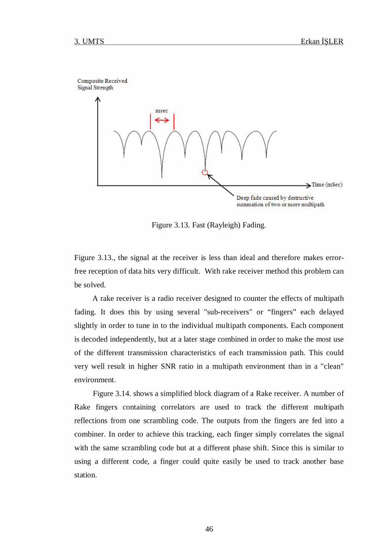
3. UMTS Erkan İŞLER
46
Figure 3.13. Fast (Rayleigh) Fading.
Figure 3.13., the signal at the receiver is less than ideal and therefore makes error-
free reception of data bits very difficult. With rake receiver method this problem can
be solved.
A rake receiver is a radio receiver designed to counter the effects of multipath
fading. It does this by using several "sub-receivers" or “fingers” each delayed
slightly in order to tune in to the individual multipath components. Each component
is decoded independently, but at a later stage combined in order to make the most use
of the different transmission characteristics of each transmission path. This could
very well result in higher SNR ratio in a multipath environment than in a "clean"
environment.
Figure 3.14. shows a simplified block diagram of a Rake receiver. A number of
Rake fingers containing correlators are used to track the different multipath
reflections from one scrambling code. The outputs from the fingers are fed into a
combiner. In order to achieve this tracking, each finger simply correlates the signal
with the same scrambling code but at a different phase shift. Since this is similar to
using a different code, a finger could quite easily be used to track another base
station.
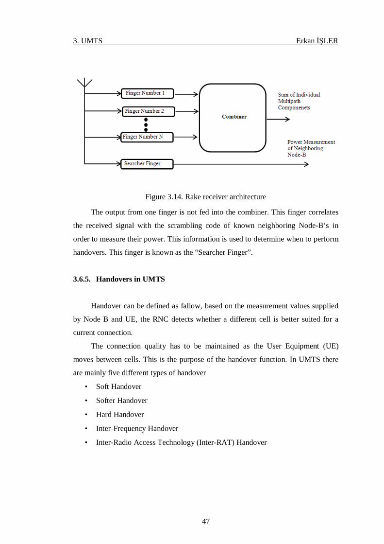
3. UMTS Erkan İŞLER
47
Figure 3.14. Rake receiver architecture
The output from one finger is not fed into the combiner. This finger correlates
the received signal with the scrambling code of known neighboring Node-B’s in
order to measure their power. This information is used to determine when to perform
handovers. This finger is known as the “Searcher Finger”.
3.6.5. Handovers in UMTS
Handover can be defined as fallow, based on the measurement values supplied
by Node B and UE, the RNC detects whether a different cell is better suited for a
current connection.
The connection quality has to be maintained as the User Equipment (UE)
moves between cells. This is the purpose of the handover function. In UMTS there
are mainly five different types of handover
• Soft Handover
• Softer Handover
• Hard Handover
• Inter-Frequency Handover
• Inter-Radio Access Technology (Inter-RAT) Handover

3. UMTS Erkan İŞLER
48
3.6.5.1. Soft Handover
In Soft Handover the UE is connected to more than one Radio Base Station
(RBS) simultaneously. At least one radio link is always active and there is no
interruption in the dataflow during the actual handover.
3.6.5.2. Softer Handover
In Softer Handover the UE communicates with one RBS through several radio
links, the Softer Handover is a handover between two or more cells of the same RBS.
3.6.5.3. Hard Handover
Hard handover means that all the old radio links in the UE are removed before
the new radio links are established. Hard handover can be seamless or non-seamless.
Seamless hard handover means that the handover is not perceptible to the user.
3.6.5.4. Inter-Frequency Handover
Inter-Frequency Handover takes place when the UE makes a Handover (HO) to
another WCDMA frequency. This is a form of hard handover.
3.6.5.5. Inter-Radio Access Technology (Inter-RAT) Handover
The Inter-RAT Handover function preserves signal quality on dedicated
channels for circuit switched services when the UE is moving from a WCDMA
network to a GSM network and vice versa. This is also a form of hard handover.
4. LTE Erkan İŞLER
49
4. LTE
4.1. Introduction
The second generation mobile networks were originally designed for carrying
voice traffic while the data capability was added later. Data usage has increased but
the traffic volume in second generation networks is clearly dominated by voice
traffic. The introduction of third generation networks with High Speed Downlink
Packet Access (HSDPA) has boosted data usage considerably.
In short, the introduction of HSDPA has changed mobile networks from voice
dominated to packet data dominated networks. Data usage is advanced by a number
of bandwidth laptop applications including internet and intranet access, file sharing,
streaming services to distribute video content and mobile TV and interactive gaming.
In addition, service bundles of video, data and voice are entering the mobile market,
also replacing the traditional fixed line voice and broadband data services with
mobile services both at home and in the office. A typical voice subscriber uses 300
minutes per month, which is equal to approximately 30 megabyte of data with a
voice data rate of 12.2 kbps. A broadband data user can easily consume more than
1000 megabyte (1 gigabyte) of data. Heavy broadband data usage takes 10–100×
more capacity than voice usage, which sets high requirements for the capacity and
efficiency of network data.
It is expected that by 2015, 5 billion people will be connected to the internet.
Broadband internet connections will be available practically anywhere in the world.
Already today, the existing wireline installations can reach approximately 1 billion
households and the mobile networks connect over 3 billion subscribers. These
installations need to evolve into broadband internet access.
LTE is the next generation mobile telecommunication technology and it is a
project of the Third Generation Partnership Project to improve the UMTS mobile
phone standard to cope with future technology evolutions.
LTE offers several important benefits for consumers and operators:
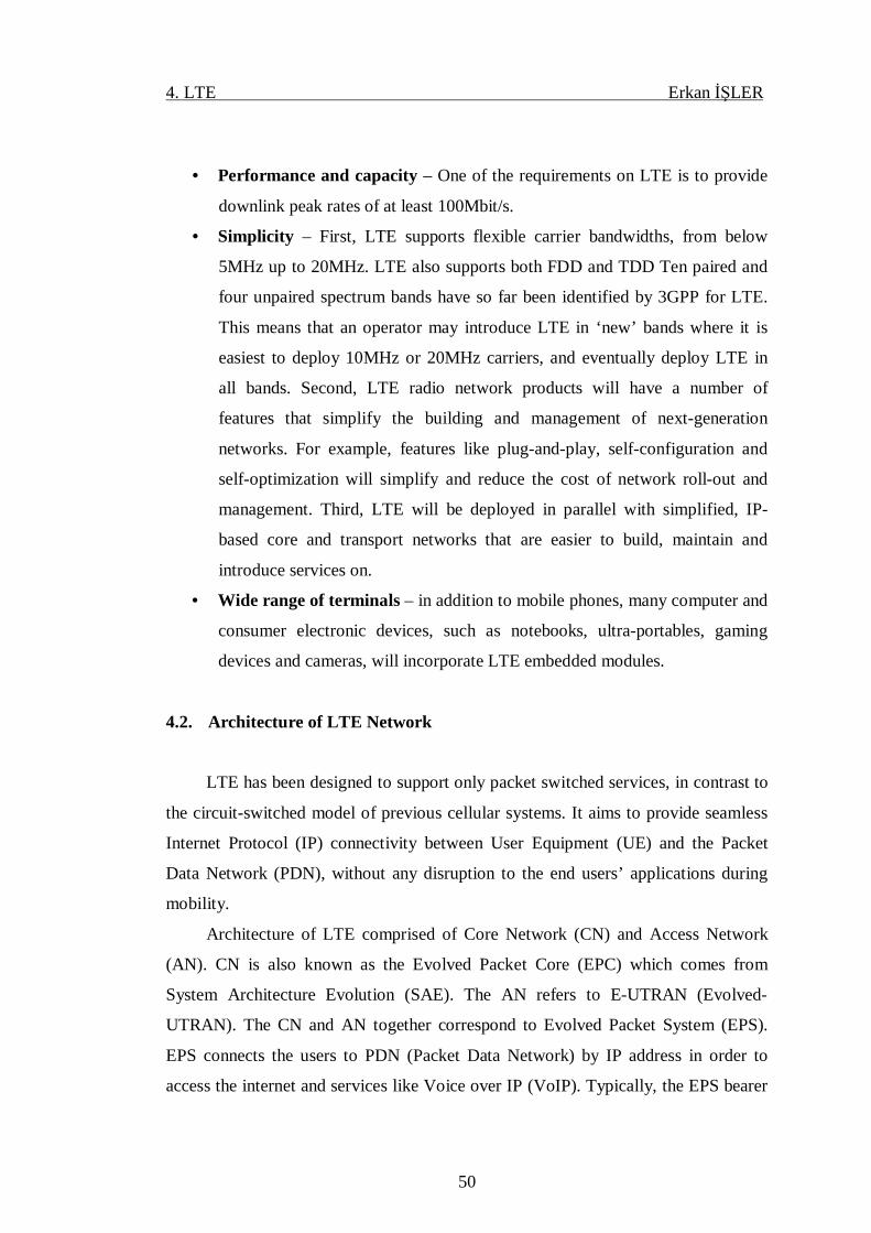
4. LTE Erkan İŞLER
50
• Performance and capacity – One of the requirements on LTE is to provide
downlink peak rates of at least 100Mbit/s.
• Simplicity – First, LTE supports flexible carrier bandwidths, from below
5MHz up to 20MHz. LTE also supports both FDD and TDD Ten paired and
four unpaired spectrum bands have so far been identified by 3GPP for LTE.
This means that an operator may introduce LTE in ‘new’ bands where it is
easiest to deploy 10MHz or 20MHz carriers, and eventually deploy LTE in
all bands. Second, LTE radio network products will have a number of
features that simplify the building and management of next-generation
networks. For example, features like plug-and-play, self-configuration and
self-optimization will simplify and reduce the cost of network roll-out and
management. Third, LTE will be deployed in parallel with simplified, IP-
based core and transport networks that are easier to build, maintain and
introduce services on.
• Wide range of terminals – in addition to mobile phones, many computer and
consumer electronic devices, such as notebooks, ultra-portables, gaming
devices and cameras, will incorporate LTE embedded modules.
4.2. Architecture of LTE Network
LTE has been designed to support only packet switched services, in contrast to
the circuit-switched model of previous cellular systems. It aims to provide seamless
Internet Protocol (IP) connectivity between User Equipment (UE) and the Packet
Data Network (PDN), without any disruption to the end users’ applications during
mobility.
Architecture of LTE comprised of Core Network (CN) and Access Network
(AN). CN is also known as the Evolved Packet Core (EPC) which comes from
System Architecture Evolution (SAE). The AN refers to E-UTRAN (Evolved-
UTRAN). The CN and AN together correspond to Evolved Packet System (EPS).
EPS connects the users to PDN (Packet Data Network) by IP address in order to
access the internet and services like Voice over IP (VoIP). Typically, the EPS bearer
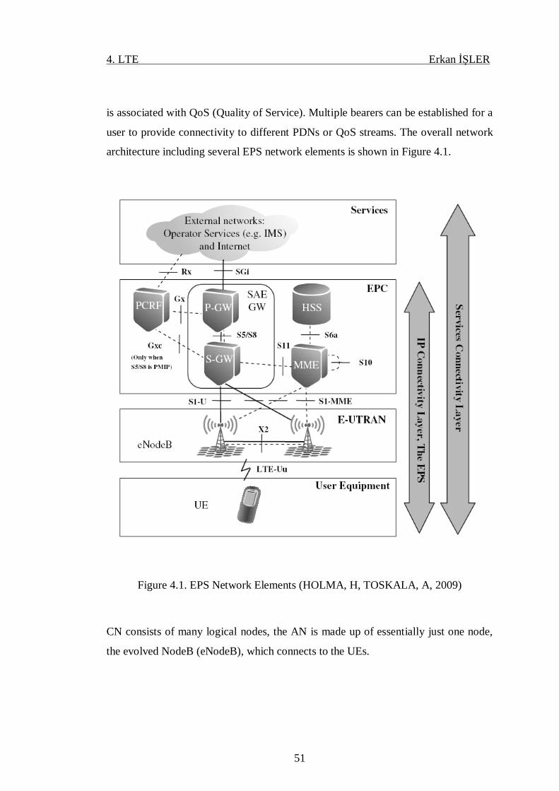
4. LTE Erkan İŞLER
51
is associated with QoS (Quality of Service). Multiple bearers can be established for a
user to provide connectivity to different PDNs or QoS streams. The overall network
architecture including several EPS network elements is shown in Figure 4.1.
Figure 4.1. EPS Network Elements (HOLMA, H, TOSKALA, A, 2009)
CN consists of many logical nodes, the AN is made up of essentially just one node,
the evolved NodeB (eNodeB), which connects to the UEs.
4. LTE Erkan İŞLER
52
4.2.1. Core Network
Core network is also referred to as Evolved Packet Core (EPC) in SAE. The
CN is responsible for establishment of the bearers and control of the UE. EPC consist
of fallowing logical nodes.
• Mobility Management Entity (MME)
• Packet Data Network Gateway (P-GW)
• Serving Gateway (S-GW)
• Policy Control and Charging Rules Function (PCRF)
• Home Subscriber Server (HSS)
Mobility Management Entity:
MME is the main control element in the EPC. It used to process signalling
between the CN and the UE. The protocols running between the UE and the CN are
called as the Non-Access Stratum (NAS) protocols. The main MME functions are:
Bearer Management Functions: These functions used to establish, maintain and
release bearers and handled by the session management layer in the NAS protocol.
Connection Management Functions: These functions used to manage security and
connection establishment between UE and network, and handled by the mobility
management or the connection management layer in the NAS protocol layer.
Packet Data Network Gateway:
The P-GW is responsible for all the IP packet based operations for the UE as
well as flow based charging and QoS enforcement. The P-GW is responsible for the
filtering of downlink user IP packets into the different QoS based bearers.

4. LTE Erkan İŞLER
53
Serving Gateway:
S-GW is responsible for IP packet transferring. S-GW acts as the local mobility
anchor for the data bearers when the UE moves between eNodeBs. It also retains the
information about the bearers when the UE is in idle and temporarily buffers
downlink data while the MME initiates paging of the UE to re-establish the bearers.
In addition, the S-GW performs some administrative functions in the visited network
such as collecting information for charging, and legal interception. It also serves as
the mobility anchor for inter-working with other 3GPP technologies such as GPRS
and UMTS.
Policy Control and Charging Rules Function:
PCRF is the network element that is responsible for controlling the flow-based
charging functionalities. It is also responsible for Policy and Charging Control
(PCC). It makes decisions on how to handle the services in terms of QoS, and
provides information to the PCEF (Policy and Charging Enforcement Function)
located in the P-GW.
Home Subscriber Server:
HSS is also known Home Location Register (HLR). It is the subscription data
repository for all permanent user data. It also records the location of the user in the
level of visited network control node. The HSS stores the master copy of the
subscriber profile, which contains information about the services that are applicable
to the user.
4.2.2. Access Network
The Access Network is also called E-UTRAN. It consists of a network of
eNodeBs. The eNodeBs are connected to each other by means of an interface known
as X2 and to the EPC by means of the S1 interface. eNodeB is connected to MME
with S1-MME interface and connected to S-GW with S1-U interface. The protocols

4. LTE Erkan İŞLER
54
which run between the UE and the eNodeBs are known as the Access Stratum (AS)
protocols.
E-UTRAN:
The E-UTRAN is responsible for all radio-related functions. The
responsibilities of E-UTRAN are as follows:
Radio Resource Management (RRM): RRM covers radio bearers related functions
such as scheduling, radio mobility control, radio admission control, radio bearer
control, and dynamic allocation of resources in both downlink and uplink to UEs.
Header Compression: Header Compression helps to utilize efficiently the radio
interface by compressing the IP packet headers
Security: All The data sent over the radio interface is secured by encryption.
Connectivity to the EPC: Connectivity to the EPC consists of bearer path towards
S-GW and signaling towards the MME.
These functions described above reside in the eNodeBs. LTE integrates the
radio controller function into the eNodeB. This allows tight interaction between the
different protocol layers of the radio access network, thus reducing latency and
improving efficiency. Such distributed control eliminates the need for a high-
availability, processing-intensive controller, which in turn has the potential to reduce
costs and avoid ‘single points of failure’. There is no soft handover in LTE, which
eliminates the need for a centralized data combining function.

4. LTE Erkan İŞLER
55
4.3. LTE Channels for Downlink
The UE should first identify the downlink transmission from one of these cells
and synchronize with it, In order to communicate with an eNodeB. The next step for
the UE is to estimate the downlink radio channel in order to be able to perform
coherent demodulation of the information-bearing parts of the downlink signal.
LTE channels for downlink consist of logical channels, transport channels and
physical channels. Figure 4.2. shows the LTE Downlink Channels.
Figure 4.2. LTE Downlink Channels and Mapping to Higher Layers
4.3.1. LTE Logical Channels for Downlink
LTE logical channels are classified into control logical channels and traffic
logical channels. Control logical channels carry control information and traffic
control channels carry user plan information whereas user plan information is carried
out by traffic control channels
LTE logical channels are defined for different data transfer services. LTE logical
channels comprise of the fallowing channels.

4. LTE Erkan İŞLER
56
• Paging Control Channel (PCCH): PCCH is a downlink channel that
transfers paging information and system information change notifications.
This channel is used for paging when the network does not know the location
cell of the UE.
• Broadcast Control Channel (BCCH): BCCH is a downlink channel for
broadcasting system information.
• Common Control Channel (CCCH): CCCH is used to transmit control
information between UEs and network when there is no confirmed
association between a UE and the eNodeB.
• Dedicated Control Channel (DCCH): DCCH is used to transmit dedicated
control information relating to a specific UE.
• Dedicated Traffic Channel (DTCH): DTCH is used to transmit dedicated
user data.
• Multicast Control Channel (MCCH): MCCH is a downlink channel. It is
used to transmit control information related to the reception of MBMS
(Multimedia Broadcast Multicast Service) services.
• Multicast Traffic Channel (MTCH): MTCH is used is used to transmit user
data for MBMS services in the downlink
4.3.2. LTE Transport Channels for Downlink
LTE transport channels act as an interface or Service Access Points (SAPs)
between the MAC and physical layer. Data is multiplexed into transport channels
depending on how it is transmitted over the air.LTE transport channels comprise of
the fallowing channels.

4. LTE Erkan İŞLER
57
• Paging Channel (PCH): PCH is used to transport paging information to
UEs. This channel is also used to inform UEs about updates of the system
information.
• Broadcast Channel (BCH): BCH is used to transport the parts of the system
information which are essential for access to the DL-SCH. The transport
format is fixed and the capacity is limited.
• Downlink Shared Channel (DL-SCH): DL-SCH is used to transport
downlink user data or control messages. In addition, the remaining parts of
the system information that are not transported via the BCH are transported
on the DL-SCH.
• Multicast Channel (MCH): MCH is used to transport user data or control
messages that require MBSFN (Multimedia Broadcast Single Frequency
Network) combining.
4.3.3. LTE Physical Channels for Downlink
LTE physical channels carry information from upper layers of the LTE stack.
Physical channels are mapped into transport channels. LTE physical channels
comprise of the fallowing channels.
• Physical Broadcast Channel (PBCH): PBCH carries the system information
needed to access the system. PBCH periodically sends (every 40
milliseconds) system identification and access control parameters.
• Physical Downlink Shared Channel (PDSCH): PDSCH is the main data-
bearing downlink channel in LTE. It is used for all user data, as well as for
broadcast system information which is not carried on the PBCH, and for
paging messages – there is no specific physical layer paging channel in the
LTE system.
4. LTE Erkan İŞLER
58
• Physical Multicast Channel (PMCH): PMCH is very similar to the
PDSCH. However, the PMCH is designed for ‘single-frequency network’
operation, whereby multiple cells transmit the same modulated symbols with
very tight time-synchronization, ideally so that the signals from different cells
are received within the duration of the cyclic prefix. This is known as
MBSFN (MBMS Single Frequency Network) operation.
• Physical Downlink Control Channel (PDCCH): A PDCCH carries a
message known as Downlink Control Information (DCI), which includes
resource assignments and other control information for a UE or group of UEs.
In general, several PDCCHs can be transmitted in a subframe.
• Physical Hybrid ARQ Indicator Channel (PHICH): The PHICH carries
the HARQ (Hybrid Adaptive Repeat and Request) ACK/NACK,
(Acknowledgement /Negative Acknowledgement) which indicates whether
the eNodeB has correctly received a transmission on the PUSCH (Physical
Uplink Shared Channel).
4.4. LTE Channels for Uplink
LTE uplink channels state information is estimated based on the SRS
(Sounding Reference Signals) transmitted by the UE. SRS is used for channel quality
determination to enable frequency-selective scheduling on the uplink. LTE channels
for uplink consist of logical channels, transport channels and physical channels.
Figure 4.3. shows the LTE Uplink Channels.

4. LTE Erkan İŞLER
59
Figure 4.3. LTE Uplink Channels and Mapping to Higher Layers
4.4.1. LTE Logical Channels Uplink
LTE logical channels are defined for different data transfer services. LTE
logical channels comprise of the fallowing channels.
• Common Control Channel (CCCH): CCCH is used to deliver control
information in both uplink and downlink directions when there is no
confirmed association between a UE and the eNodeB – i.e. during connection
establishment
• Dedicated Control Channel (DCCH): DCCH is used to transmit dedicated
control information relating to a specific UE, in both uplink and downlink
directions.
• Dedicated Traffic Channel (DTCH): DTCH is used to transmit dedicated
user data in both uplink and downlink directions
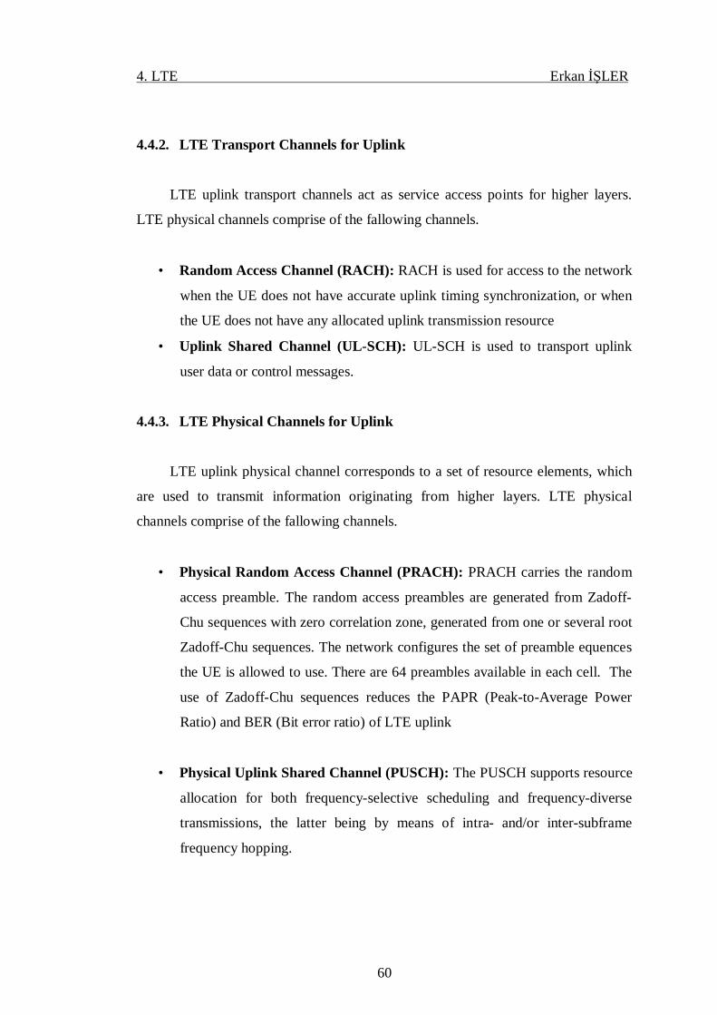
4. LTE Erkan İŞLER
60
4.4.2. LTE Transport Channels for Uplink
LTE uplink transport channels act as service access points for higher layers.
LTE physical channels comprise of the fallowing channels.
• Random Access Channel (RACH): RACH is used for access to the network
when the UE does not have accurate uplink timing synchronization, or when
the UE does not have any allocated uplink transmission resource
• Uplink Shared Channel (UL-SCH): UL-SCH is used to transport uplink
user data or control messages.
4.4.3. LTE Physical Channels for Uplink
LTE uplink physical channel corresponds to a set of resource elements, which
are used to transmit information originating from higher layers. LTE physical
channels comprise of the fallowing channels.
• Physical Random Access Channel (PRACH): PRACH carries the random
access preamble. The random access preambles are generated from Zadoff-
Chu sequences with zero correlation zone, generated from one or several root
Zadoff-Chu sequences. The network configures the set of preamble equences
the UE is allowed to use. There are 64 preambles available in each cell. The
use of Zadoff-Chu sequences reduces the PAPR (Peak-to-Average Power
Ratio) and BER (Bit error ratio) of LTE uplink
• Physical Uplink Shared Channel (PUSCH): The PUSCH supports resource
allocation for both frequency-selective scheduling and frequency-diverse
transmissions, the latter being by means of intra- and/or inter-subframe
frequency hopping.

4. LTE Erkan İŞLER
61
• Physical Uplink Control Channel (PUCCH): Control signalling (consisting
of ACK/NACK, CQI/PMI and RI) is carried by the PUCCH when no PUSCH
resources have been allocated.
4.5. Multiple Antenna Techniques in LTE
Utilizing multiple antennas at the receiver and transmitter improves the data
rate on longer range without consuming extra bandwidth or transmit power. This
technology is referred as multiple-input multiple-output (MIMO) communication
MIMO is one of the technologies introduced together with the LTE
4.5.1. LTE MIMO
MIMO is a technology which offers significant increases in data throughput
and link range without additional bandwidth or transmit power. The basic principle
of MIMO is shown in Figure 4.4.
Figure 4.4. Basic Principle of MIMO
In LTE downlink, 2x2 and 4x4 configurations can be used. MIMO modes can
be classified according to condition of the channels.
• Spatial Multiplexing: MIMO system is also used to increase data rate by
spatial multiplexing. Spatial multiplexing creates independent signaling paths
to send independent data and assumes accurate channel knowledge at the
receiver. In the other words, spatial multiplexing is sending signals from two
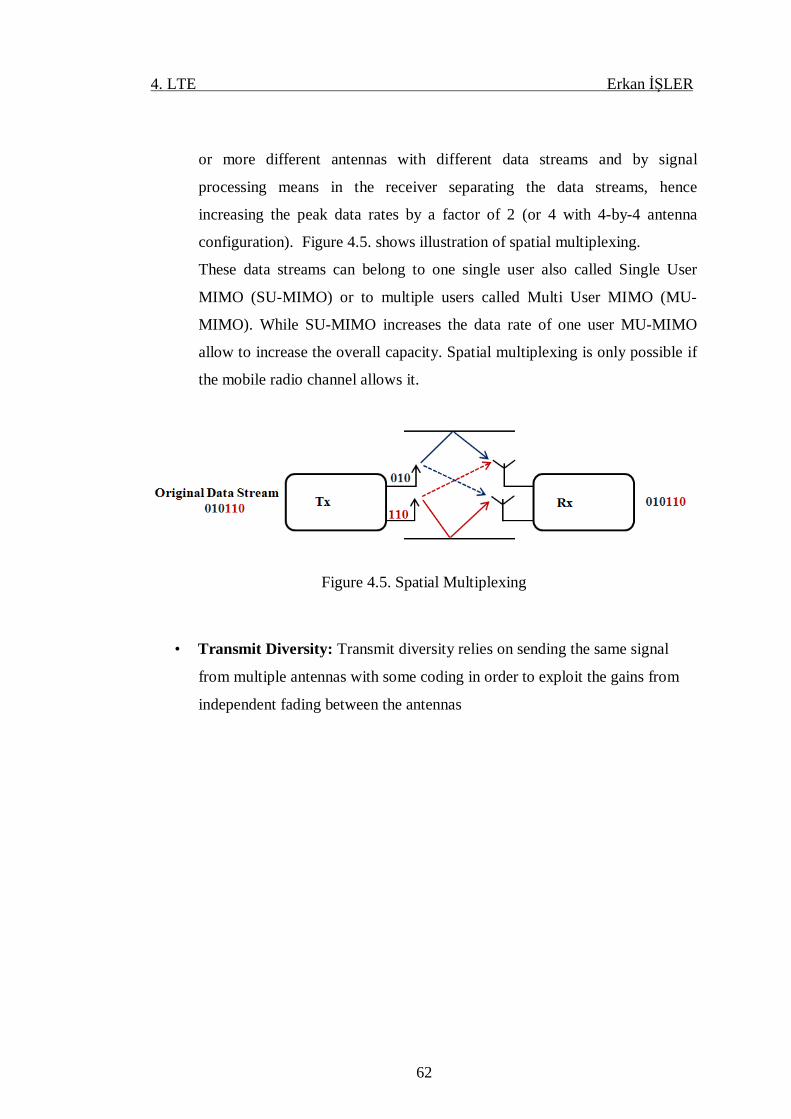
4. LTE Erkan İŞLER
62
or more different antennas with different data streams and by signal
processing means in the receiver separating the data streams, hence
increasing the peak data rates by a factor of 2 (or 4 with 4-by-4 antenna
configuration). Figure 4.5. shows illustration of spatial multiplexing.
These data streams can belong to one single user also called Single User
MIMO (SU-MIMO) or to multiple users called Multi User MIMO (MU-
MIMO). While SU-MIMO increases the data rate of one user MU-MIMO
allow to increase the overall capacity. Spatial multiplexing is only possible if
the mobile radio channel allows it.
Figure 4.5. Spatial Multiplexing
• Transmit Diversity: Transmit diversity relies on sending the same signal
from multiple antennas with some coding in order to exploit the gains from
independent fading between the antennas
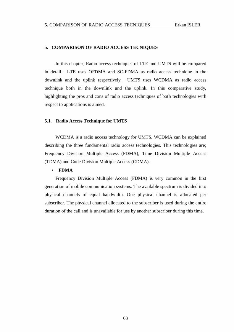
5. COMPARISON OF RADIO ACCESS TECNIQUES Erkan İŞLER
63
5. COMPARISON OF RADIO ACCESS TECNIQUES
In this chapter, Radio access techniques of LTE and UMTS will be compared
in detail. LTE uses OFDMA and SC-FDMA as radio access technique in the
downlink and the uplink respectively. UMTS uses WCDMA as radio access
technique both in the downlink and the uplink. In this comparative study,
highlighting the pros and cons of radio access techniques of both technologies with
respect to applications is aimed.
5.1. Radio Access Technique for UMTS
WCDMA is a radio access technology for UMTS. WCDMA can be explained
describing the three fundamental radio access technologies. This technologies are;
Frequency Division Multiple Access (FDMA), Time Division Multiple Access
(TDMA) and Code Division Multiple Access (CDMA).
• FDMA
Frequency Division Multiple Access (FDMA) is very common in the first
generation of mobile communication systems. The available spectrum is divided into
physical channels of equal bandwidth. One physical channel is allocated per
subscriber. The physical channel allocated to the subscriber is used during the entire
duration of the call and is unavailable for use by another subscriber during this time.
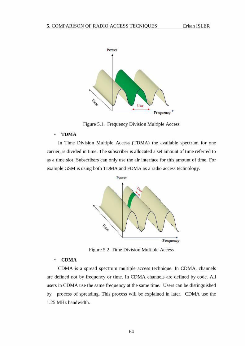
5. COMPARISON OF RADIO ACCESS TECNIQUES Erkan İŞLER
64
Figure 5.1. Frequency Division Multiple Access
• TDMA
In Time Division Multiple Access (TDMA) the available spectrum for one
carrier, is divided in time. The subscriber is allocated a set amount of time referred to
as a time slot. Subscribers can only use the air interface for this amount of time. For
example GSM is using both TDMA and FDMA as a radio access technology.
Figure 5.2. Time Division Multiple Access
• CDMA
CDMA is a spread spectrum multiple access technique. In CDMA, channels
are defined not by frequency or time. In CDMA channels are defined by code. All
users in CDMA use the same frequency at the same time. Users can be distinguished
by process of spreading. This process will be explained in later. CDMA use the
1.25 MHz bandwidth.
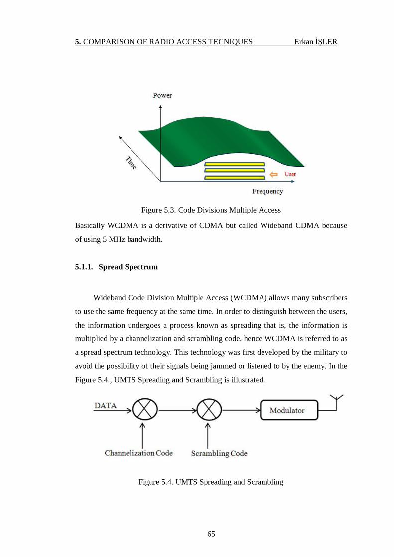
5. COMPARISON OF RADIO ACCESS TECNIQUES Erkan İŞLER
65
Figure 5.3. Code Divisions Multiple Access
Basically WCDMA is a derivative of CDMA but called Wideband CDMA because
of using 5 MHz bandwidth.
5.1.1. Spread Spectrum
Wideband Code Division Multiple Access (WCDMA) allows many subscribers
to use the same frequency at the same time. In order to distinguish between the users,
the information undergoes a process known as spreading that is, the information is
multiplied by a channelization and scrambling code, hence WCDMA is referred to as
a spread spectrum technology. This technology was first developed by the military to
avoid the possibility of their signals being jammed or listened to by the enemy. In the
Figure 5.4., UMTS Spreading and Scrambling is illustrated.
Figure 5.4. UMTS Spreading and Scrambling
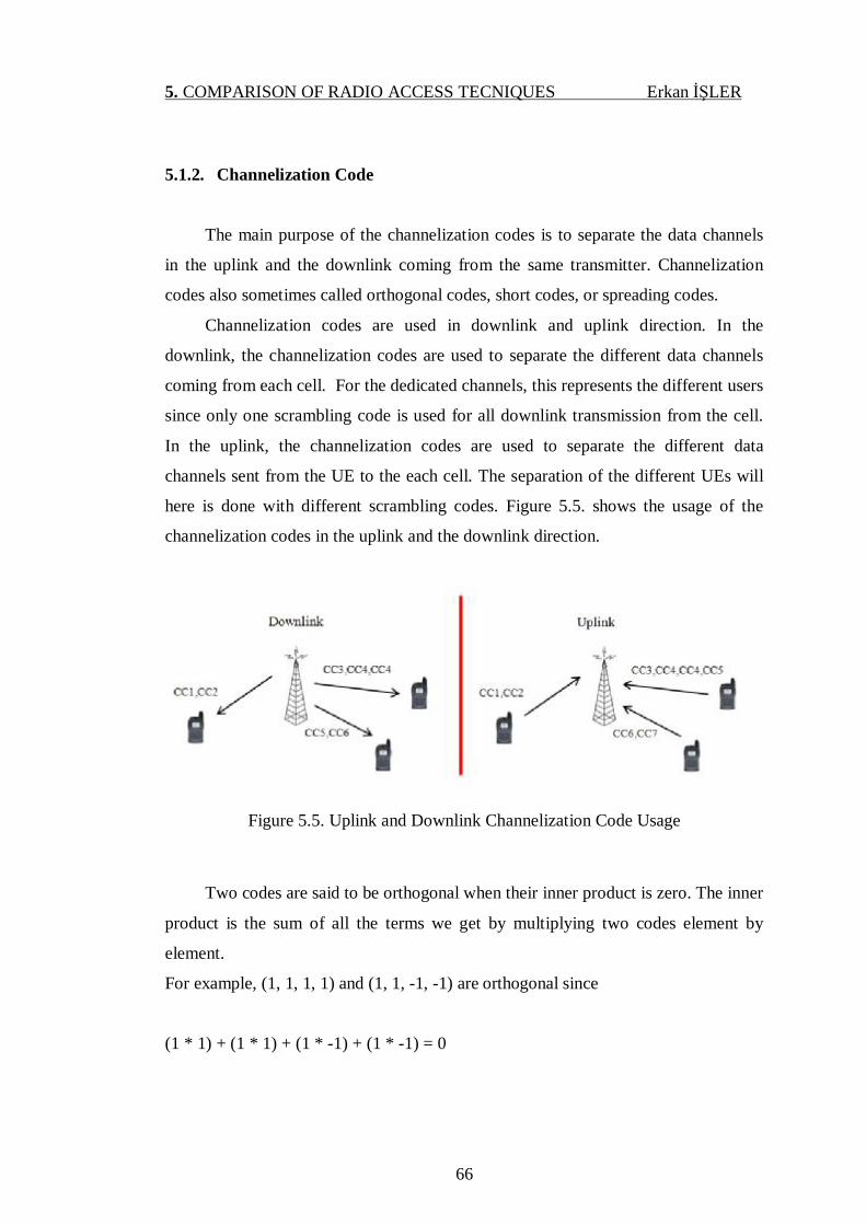
5. COMPARISON OF RADIO ACCESS TECNIQUES Erkan İŞLER
66
5.1.2. Channelization Code
The main purpose of the channelization codes is to separate the data channels
in the uplink and the downlink coming from the same transmitter. Channelization
codes also sometimes called orthogonal codes, short codes, or spreading codes.
Channelization codes are used in downlink and uplink direction. In the
downlink, the channelization codes are used to separate the different data channels
coming from each cell. For the dedicated channels, this represents the different users
since only one scrambling code is used for all downlink transmission from the cell.
In the uplink, the channelization codes are used to separate the different data
channels sent from the UE to the each cell. The separation of the different UEs will
here is done with different scrambling codes. Figure 5.5. shows the usage of the
channelization codes in the uplink and the downlink direction.
Figure 5.5. Uplink and Downlink Channelization Code Usage
Two codes are said to be orthogonal when their inner product is zero. The inner
product is the sum of all the terms we get by multiplying two codes element by
element.
For example, (1, 1, 1, 1) and (1, 1, -1, -1) are orthogonal since
(1 * 1) + (1 * 1) + (1 * -1) + (1 * -1) = 0
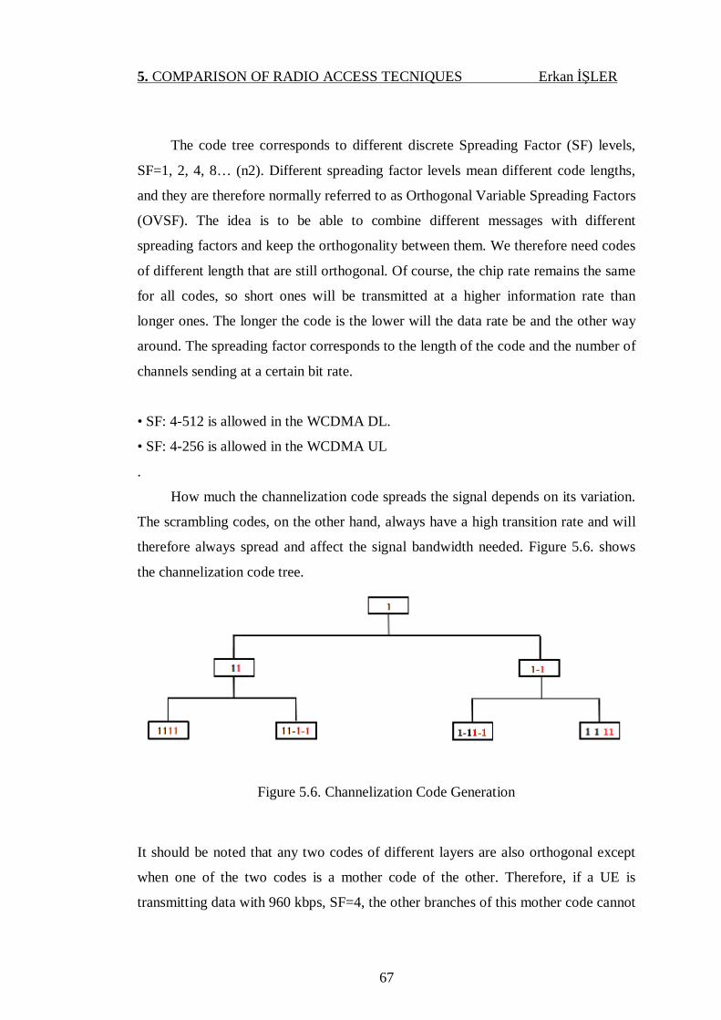
5. COMPARISON OF RADIO ACCESS TECNIQUES Erkan İŞLER
67
The code tree corresponds to different discrete Spreading Factor (SF) levels,
SF=1, 2, 4, 8… (n2). Different spreading factor levels mean different code lengths,
and they are therefore normally referred to as Orthogonal Variable Spreading Factors
(OVSF). The idea is to be able to combine different messages with different
spreading factors and keep the orthogonality between them. We therefore need codes
of different length that are still orthogonal. Of course, the chip rate remains the same
for all codes, so short ones will be transmitted at a higher information rate than
longer ones. The longer the code is the lower will the data rate be and the other way
around. The spreading factor corresponds to the length of the code and the number of
channels sending at a certain bit rate.
• SF: 4-512 is allowed in the WCDMA DL.
• SF: 4-256 is allowed in the WCDMA UL
.
How much the channelization code spreads the signal depends on its variation.
The scrambling codes, on the other hand, always have a high transition rate and will
therefore always spread and affect the signal bandwidth needed. Figure 5.6. shows
the channelization code tree.
Figure 5.6. Channelization Code Generation
It should be noted that any two codes of different layers are also orthogonal except
when one of the two codes is a mother code of the other. Therefore, if a UE is
transmitting data with 960 kbps, SF=4, the other branches of this mother code cannot
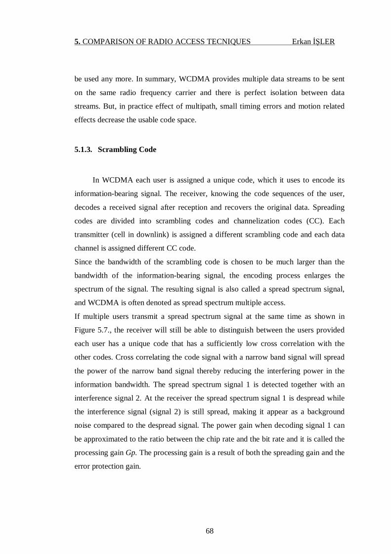
5. COMPARISON OF RADIO ACCESS TECNIQUES Erkan İŞLER
68
be used any more. In summary, WCDMA provides multiple data streams to be sent
on the same radio frequency carrier and there is perfect isolation between data
streams. But, in practice effect of multipath, small timing errors and motion related
effects decrease the usable code space.
5.1.3. Scrambling Code
In WCDMA each user is assigned a unique code, which it uses to encode its
information-bearing signal. The receiver, knowing the code sequences of the user,
decodes a received signal after reception and recovers the original data. Spreading
codes are divided into scrambling codes and channelization codes (CC). Each
transmitter (cell in downlink) is assigned a different scrambling code and each data
channel is assigned different CC code.
Since the bandwidth of the scrambling code is chosen to be much larger than the
bandwidth of the information-bearing signal, the encoding process enlarges the
spectrum of the signal. The resulting signal is also called a spread spectrum signal,
and WCDMA is often denoted as spread spectrum multiple access.
If multiple users transmit a spread spectrum signal at the same time as shown in
Figure 5.7., the receiver will still be able to distinguish between the users provided
each user has a unique code that has a sufficiently low cross correlation with the
other codes. Cross correlating the code signal with a narrow band signal will spread
the power of the narrow band signal thereby reducing the interfering power in the
information bandwidth. The spread spectrum signal 1 is detected together with an
interference signal 2. At the receiver the spread spectrum signal 1 is despread while
the interference signal (signal 2) is still spread, making it appear as a background
noise compared to the despread signal. The power gain when decoding signal 1 can
be approximated to the ratio between the chip rate and the bit rate and it is called the
processing gain Gp. The processing gain is a result of both the spreading gain and the
error protection gain.
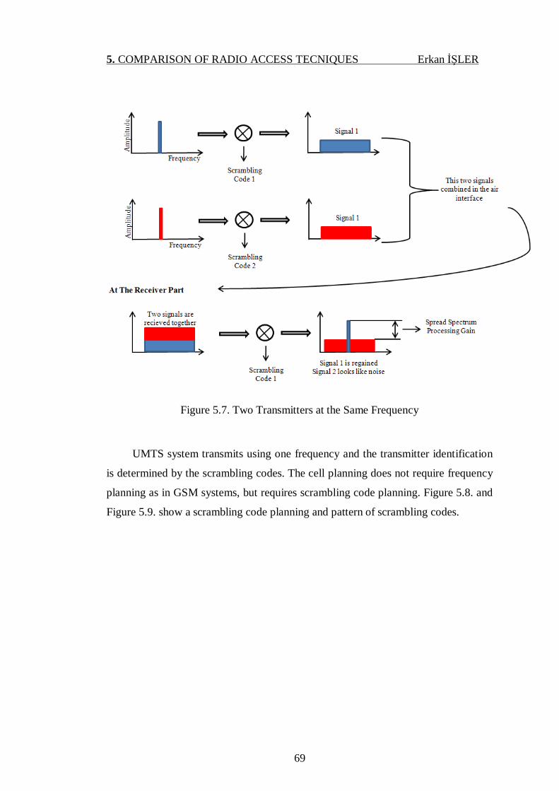
5. COMPARISON OF RADIO ACCESS TECNIQUES Erkan İŞLER
69
Figure 5.7. Two Transmitters at the Same Frequency
UMTS system transmits using one frequency and the transmitter identification
is determined by the scrambling codes. The cell planning does not require frequency
planning as in GSM systems, but requires scrambling code planning. Figure 5.8. and
Figure 5.9. show a scrambling code planning and pattern of scrambling codes.

5. COMPARISON OF RADIO ACCESS TECNIQUES Erkan İŞLER
70
Figure 5.8. Scrambling Code Planning

5. COMPARISON OF RADIO ACCESS TECNIQUES Erkan İŞLER
71
Figure 5.9. Scrambling Code Planning Example
The number of codes used in the downlink is restricted to 8192 in total. This is
done to speed up the process for the UE to find the correct scrambling code. 512 of
these are primary codes (the rest are secondary codes, 15 codes per primary) divided
into 64 code groups each group containing 8 different codes. There are no
restrictions for the number of codes generated by the 24 bits start key in the uplink
case.
5.1.4. Duplexing Method
WCDMA involves two duplexing methods. These methods are time division
duplexing (TDD) and frequency division duplexing (FDD).

5. COMPARISON OF RADIO ACCESS TECNIQUES Erkan İŞLER
72
• TDD
In TDD mode, the uplink and downlink operate with the same carrier frequency but
in different time instants, thus they are able to use unpaired bands.
• FDD
In FDD mode, the uplink and downlink transmit with different carrier frequencies,
thus requiring the allocation of paired bands.
Figure 5.10. shows the frequency band allocation of WCDMA for FDD and
TDD.
Figure 5.10. Frequency band allocation of WCDMA for FDD and TDD modes
5.1.5. Data Modulation for WCDMA
WCDMA use BPSK (Binary phase-shift keying) and QPSK (Quadrature
phase-shift keying) for data modulations in uplink and downlink respectively.
BPSK: It is also known as 2PSK. BPSK is the simplest form of phase shift
keying (PSK). In PSK, the constellation points chosen are usually positioned with
uniform angular spacing around a circle. This gives maximum phase-separation
between adjacent points and thus the best immunity to corruption. They are
positioned on a circle so that they can all be transmitted with the same energy. In this
way, the modulation of the complex numbers they represent will be the same and
thus so will the amplitudes needed for the cosine and sine waves. BPSK uses two
phases which are separated by 180°. This modulation is the most robust of all the
PSKs since it takes the highest level of noise or distortion to make the demodulator
reach an incorrect decision. It is, however, only able to modulate at 1 bit/symbol as

5. COMPARISON OF RADIO ACCESS TECNIQUES Erkan İŞLER
73
seen in the Figure 5.11. and so is unsuitable for high data-rate applications when
bandwidth is limited.
Figure 5.11. Constellation diagram example for BPSK
QPSK: It is also known as 4QAM or 4PSK. QPSK uses four points on the
constellation diagram, equispaced around a circle. In QPSK two bits are used to
represent one symbol. In Figure 5.12. shows the constellation diagram for QPSK
Figure 5.12. Constellation Diagram for QPSK
5. COMPARISON OF RADIO ACCESS TECNIQUES Erkan İŞLER
74
5.2. Radio Access Technique for LTE
LTE radio access technique is different to that of UMTS. In LTE the downlink
radio access technique is based on the Orthogonal Frequency Division Multiple
Access (OFDMA) and the uplink radio access technique is based on the Single
Carrier Frequency Division Multiple Access (SC-FDMA). These radio access
techniques provide orthogonality between the users, reducing the interference and
improving the network capacity.
5.2.1. OFDMA
It utilizes a form of FDMA, TDMA, and CDMA all together with the
advantages of Orthogonal Frequency Division Modulation (OFDM). In FDM
(Frequency Division Multiplexing), the total frequency band is divided into N
nonoverlapping frequency subcarriers. Each subcarrier is modulated with a separate
symbol and then the N subcarriers are frequency-division-multiplexed. To provide a
better interchannel interference, spectral overlap is not recommended to avoid high-
speed equalization and to combat impulsive noise and multipath distortion. However,
this leads to inefficient use of the available spectrum. To cope with this inefficiency,
the ideas proposed from mid-1960s were to use parallel data and FDM with
overlapping subchannels as can be seen in Figure 5.13. overlapping technique would
give %50 more subcarriers but reduce the adjacent interference orthogonality
between the different modulated carriers. This technique called OFDM.

5. COMPARISON OF RADIO ACCESS TECNIQUES Erkan İŞLER
75
Figure 5.13. Comparison of FDM and OFDM (a) FDM (b) OFDM
OFDMA distributes subcarriers to different users at the same time, so that
multiple users can be scheduled to receive data simultaneously. Usually, subcarriers
are allocated in contiguous groups for simplicity and to reduce the overhead of
indicating which subcarriers have been allocated to each user.
In the OFDMA, each of the center frequencies for the sub-carriers is selected from
the set that has such a difference in the frequency domain that the neighboring sub-
carriers have zero value at the sampling instant of the desired sub-carrier. The
constant frequency difference between the sub-carriers has been chosen to be 15 kHz
as shown in Figure. 5.14.
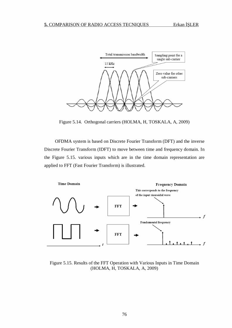
5. COMPARISON OF RADIO ACCESS TECNIQUES Erkan İŞLER
76
Figure 5.14. Orthogonal carriers (HOLMA, H, TOSKALA, A, 2009)
OFDMA system is based on Discrete Fourier Transform (DFT) and the inverse
Discrete Fourier Transform (IDFT) to move between time and frequency domain. In
the Figure 5.15. various inputs which are in the time domain representation are
applied to FFT (Fast Fourier Transform) is illustrated.
Figure 5.15. Results of the FFT Operation with Various Inputs in Time Domain (HOLMA, H, TOSKALA, A, 2009)
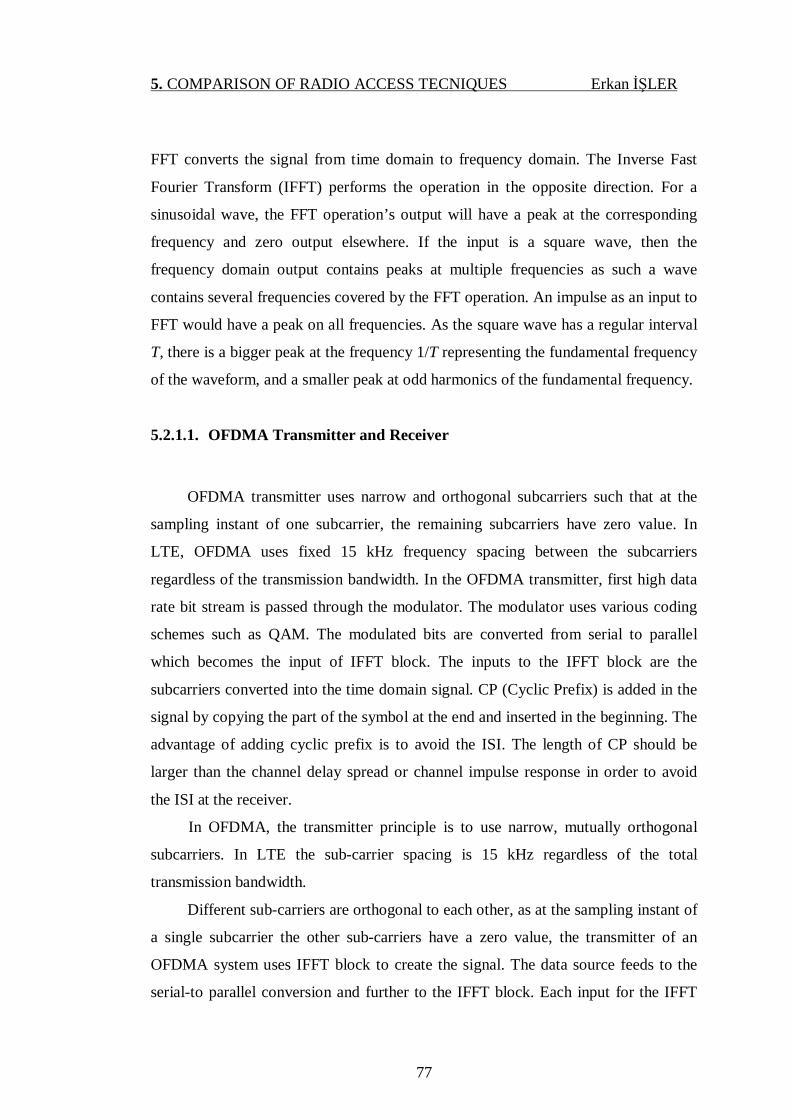
5. COMPARISON OF RADIO ACCESS TECNIQUES Erkan İŞLER
77
FFT converts the signal from time domain to frequency domain. The Inverse Fast
Fourier Transform (IFFT) performs the operation in the opposite direction. For a
sinusoidal wave, the FFT operation’s output will have a peak at the corresponding
frequency and zero output elsewhere. If the input is a square wave, then the
frequency domain output contains peaks at multiple frequencies as such a wave
contains several frequencies covered by the FFT operation. An impulse as an input to
FFT would have a peak on all frequencies. As the square wave has a regular interval
T, there is a bigger peak at the frequency 1/T representing the fundamental frequency
of the waveform, and a smaller peak at odd harmonics of the fundamental frequency.
5.2.1.1. OFDMA Transmitter and Receiver
OFDMA transmitter uses narrow and orthogonal subcarriers such that at the
sampling instant of one subcarrier, the remaining subcarriers have zero value. In
LTE, OFDMA uses fixed 15 kHz frequency spacing between the subcarriers
regardless of the transmission bandwidth. In the OFDMA transmitter, first high data
rate bit stream is passed through the modulator. The modulator uses various coding
schemes such as QAM. The modulated bits are converted from serial to parallel
which becomes the input of IFFT block. The inputs to the IFFT block are the
subcarriers converted into the time domain signal. CP (Cyclic Prefix) is added in the
signal by copying the part of the symbol at the end and inserted in the beginning. The
advantage of adding cyclic prefix is to avoid the ISI. The length of CP should be
larger than the channel delay spread or channel impulse response in order to avoid
the ISI at the receiver.
In OFDMA, the transmitter principle is to use narrow, mutually orthogonal
subcarriers. In LTE the sub-carrier spacing is 15 kHz regardless of the total
transmission bandwidth.
Different sub-carriers are orthogonal to each other, as at the sampling instant of
a single subcarrier the other sub-carriers have a zero value, the transmitter of an
OFDMA system uses IFFT block to create the signal. The data source feeds to the
serial-to parallel conversion and further to the IFFT block. Each input for the IFFT

5. COMPARISON OF RADIO ACCESS TECNIQUES Erkan İŞLER
78
block corresponds to the input representing a particular sub-carrier and can be
modulated independently of the other sub-carriers. The IFFT block is followed by
adding the cyclic extension (cyclix prefix), as shown in Figure 5.16.
The advantage of adding cyclic prefix (CP) is to avoid inter symbol
interference (ISI). The length of CP should be longer than the channel impulse
response order to avoid the ISI at the receiver.
The receiver performs the inverse procedure of transmitter. First removes the
CP extension followed by serial to parallel conversion after the subcarriers are
passed to FFT block which converts them into a frequency domain signal. Finally the
frequency domain signal is demodulated and equalized.
The Transmitter and Receiver block diagram of OFDMA is illustrated in Figure 5-17
Figure 5.16. Transmitter and Receiver Block Diagram of OFDMA (HOLMA, H, TOSKALA, A, 2009)

5. COMPARISON OF RADIO ACCESS TECNIQUES Erkan İŞLER
79
In OFDMA, users are allocated a specific number of subcarriers for a
predetermined amount of time. These are referred to as physical resource blocks
(PRBs) in the LTE specifications. PRBs thus have both a time and frequency
dimension. Allocation of PRBs is handled by a scheduling function at the eNodeB.
Figure 5.17. LTE Generic Frame Structure (ZYREN, J, 2007)
LTE frames are 10 msec in duration. They are divided into 10 subframes, each
subframe being 1 msec long. Each subframe is further divided into two slots, each of
0.5 msec duration. Slots consist of either 6 or 7 ODFM symbols, depending on
whether the normal or extended cyclic prefix is employed. The total number of
available subcarriers depends on the overall transmission bandwidth of the system as
shown in figure 5.17. The LTE specifications define parameters for system
bandwidths from 1.4 MHz to 20 MHz as shown in Table 5.1.
Bandwidth (MHz) 1.4 3 5 10 15 20 Subcarrier Bandwidth (KHz) 15
Physical Resource Block (PRB) Bandwidth (kHz) 180
Number Of Available PRBs 6 15 25 50 75 100
Table 5.1. Available Downlink Bandwidth is Divided into Physical Resource Blocks
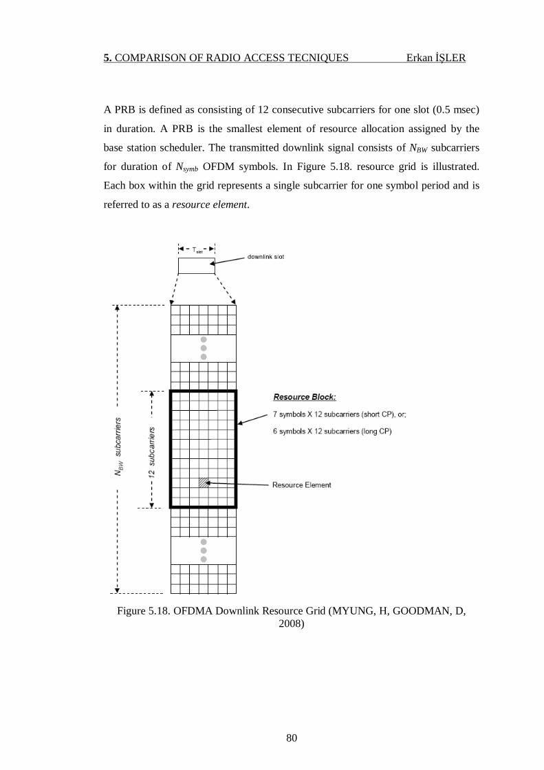
5. COMPARISON OF RADIO ACCESS TECNIQUES Erkan İŞLER
80
A PRB is defined as consisting of 12 consecutive subcarriers for one slot (0.5 msec)
in duration. A PRB is the smallest element of resource allocation assigned by the
base station scheduler. The transmitted downlink signal consists of NBW subcarriers
for duration of Nsymb OFDM symbols. In Figure 5.18. resource grid is illustrated.
Each box within the grid represents a single subcarrier for one symbol period and is
referred to as a resource element.
Figure 5.18. OFDMA Downlink Resource Grid (MYUNG, H, GOODMAN, D,
2008)

5. COMPARISON OF RADIO ACCESS TECNIQUES Erkan İŞLER
81
5.2.2. SCFDMA
Single Carrier Frequency Division Multiple Access (SC-FDMA) is multi user
version of Single carrier modulation with frequency domain equalization (SC/FDE)
scheme.
SC/FDE delivers performance similar to OFDM with essentially the same
overall complexity, even for a long channel impulse response. Figure 5.19. shows the
block diagrams of an SC/FDE receiver and, for comparison, an OFDM receiver.
Both systems use the same communication component blocks and the only difference
between the two diagrams is the location of the IDFT block. Thus, one can expect the
two systems to have similar link level performance and spectral efficiency.
An SC/FDE modulator transmits modulation symbols sequentially. It divides the
sequence of modulation symbols into blocks and adds a CP to the beginning of each
block. The CP is a copy of the last part of the block. As in OFDM, the CP prevents
inter-block interference. It also ensures that the convolution of the channel impulse
response with the modulated symbols has the form of a circular convolution. This
matches the signal processing performed by the channel with the signal processing
performed by the FDE because multiplication in the DFT-domain is equivalent to
circular convolution in the time domain.

5. COMPARISON OF RADIO ACCESS TECNIQUES Erkan İŞLER
82
*PS: Pulse Shaping
Figure 5.19 Block diagrams of SC/FDE and OFDM systems (MYUNG, H, GOODMAN, D, 2008)
5.2.2.1. SC-FDMA Transmitter and Receiver
SC-FDMA has similar structure and performance to OFDMA. The basic form
of SC-FDMA could be seen as equal to the QAM modulation, where each symbol is
sent one at a time. Frequency domain generation of the signal, as shown in Figure
5.20., adds the OFDMA property of good spectral waveform in contrast to time
domain signal generation with a regular QAM modulator. Thus the need for guard
bands between different users can be avoided, similar to the downlink OFDMA
principle. As in an OFDMA system, a cyclic prefix is also added periodically – but
not after each symbol as the symbol rate is faster in the time domain than in OFDMA
– to the transmission to prevent inter-symbol interference and to simplify the receiver
design. The receiver still needs to deal with inter-symbol interference as the cyclic
prefix now prevents inter-symbol interference between a block of symbols, and thus
there will still be inter-symbol interference between the cyclic prefixes. The receiver
will thus run the equalizer for a block of symbols until reaching the cyclic prefix that
prevents further propagation of the inter-symbol interference.

5. COMPARISON OF RADIO ACCESS TECNIQUES Erkan İŞLER
83
Figure 5.20 Transmitter and Receiver Block Diagram of SC-FDMA (HOLMA, H, TOSKALA, A, 2009)
SC-FDMA arranges subcarriers in PRBs similar to OFDMA. A PRB is comprised of
12 consecutive subcarriers for the duration of one time slot of LTE frame (1slot = 0.5
ms). Two types of CP are used in uplink, the normal and extended CP having 7 and 6
SC-FDMA symbols respectively. Due to the fixed size of PRB’s, uplink supports
flexible transmission bandwidths similar to downlink. The SC-FDMA uplink
resource grid is shown in Figure 5.21.
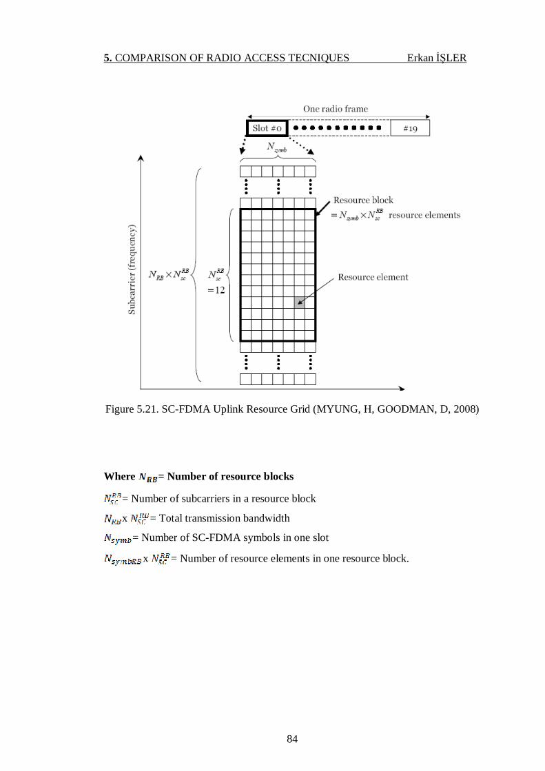
5. COMPARISON OF RADIO ACCESS TECNIQUES Erkan İŞLER
84
Figure 5.21. SC-FDMA Uplink Resource Grid (MYUNG, H, GOODMAN, D, 2008)
Where = Number of resource blocks
= Number of subcarriers in a resource block
x = Total transmission bandwidth
= Number of SC-FDMA symbols in one slot
x = Number of resource elements in one resource block.
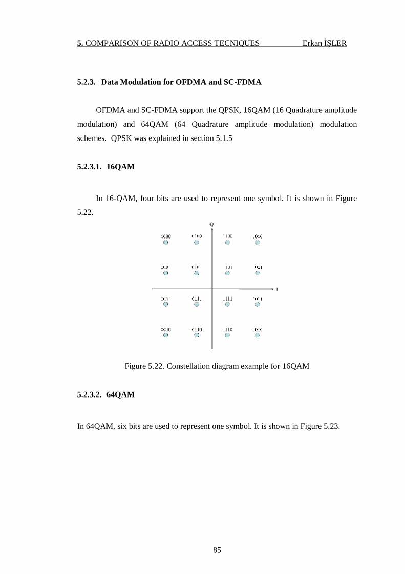
5. COMPARISON OF RADIO ACCESS TECNIQUES Erkan İŞLER
85
5.2.3. Data Modulation for OFDMA and SC-FDMA
OFDMA and SC-FDMA support the QPSK, 16QAM (16 Quadrature amplitude
modulation) and 64QAM (64 Quadrature amplitude modulation) modulation
schemes. QPSK was explained in section 5.1.5
5.2.3.1. 16QAM
In 16-QAM, four bits are used to represent one symbol. It is shown in Figure
5.22.
Figure 5.22. Constellation diagram example for 16QAM
5.2.3.2. 64QAM
In 64QAM, six bits are used to represent one symbol. It is shown in Figure 5.23.
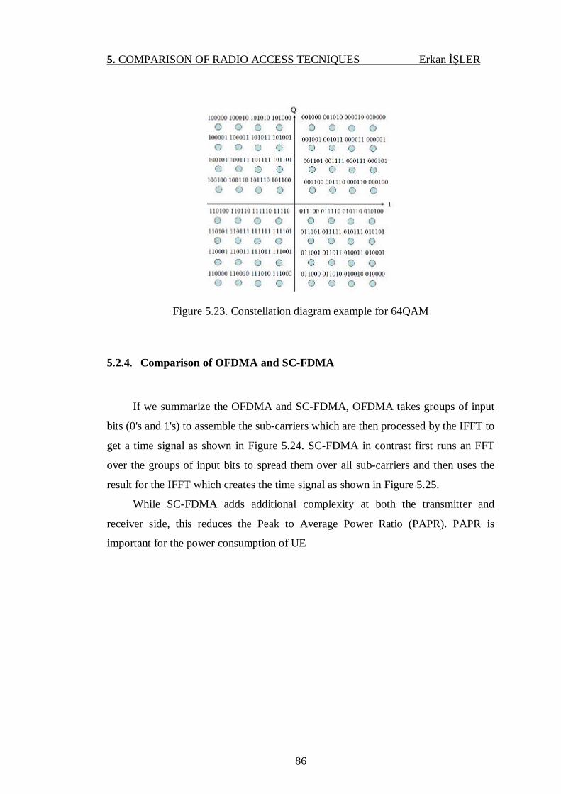
5. COMPARISON OF RADIO ACCESS TECNIQUES Erkan İŞLER
86
Figure 5.23. Constellation diagram example for 64QAM
5.2.4. Comparison of OFDMA and SC-FDMA
If we summarize the OFDMA and SC-FDMA, OFDMA takes groups of input
bits (0's and 1's) to assemble the sub-carriers which are then processed by the IFFT to
get a time signal as shown in Figure 5.24. SC-FDMA in contrast first runs an FFT
over the groups of input bits to spread them over all sub-carriers and then uses the
result for the IFFT which creates the time signal as shown in Figure 5.25.
While SC-FDMA adds additional complexity at both the transmitter and
receiver side, this reduces the Peak to Average Power Ratio (PAPR). PAPR is
important for the power consumption of UE
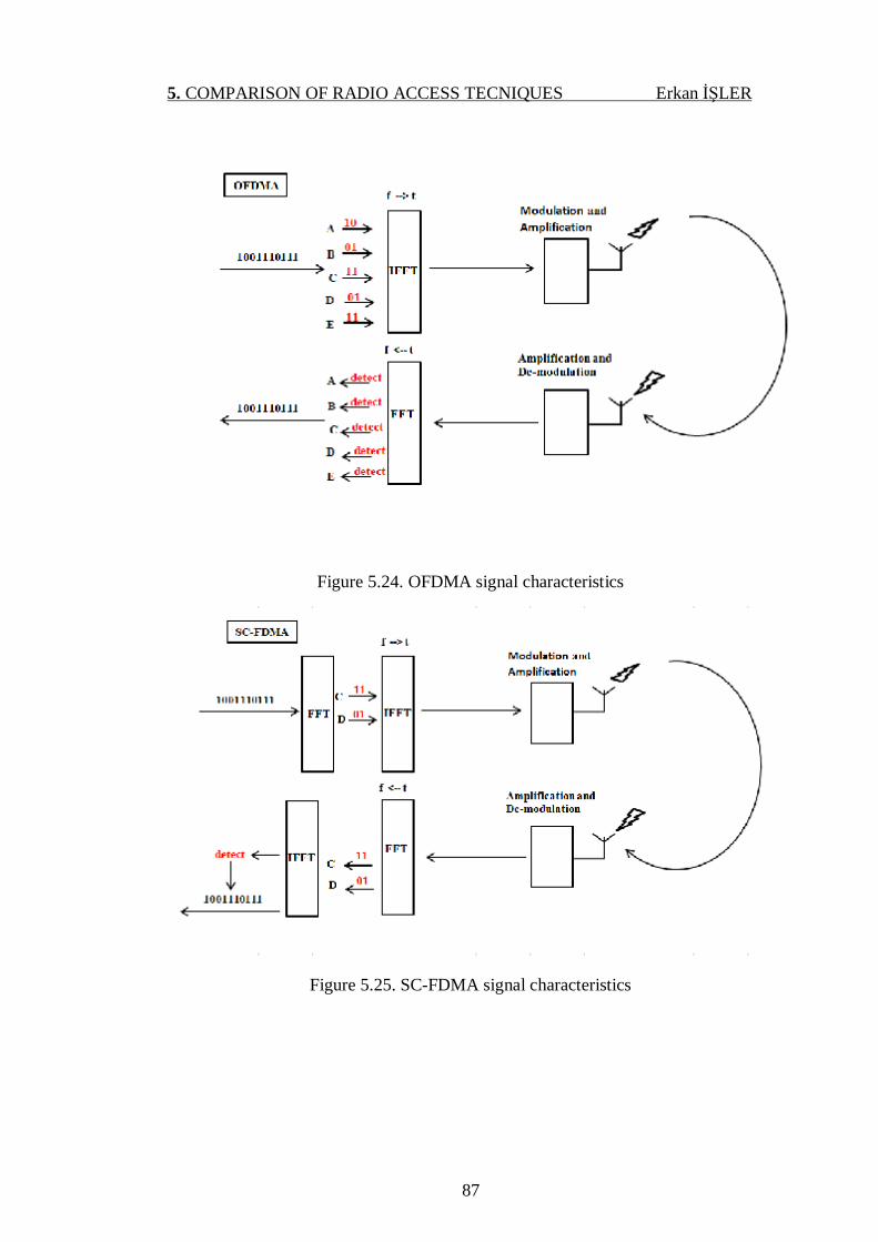
5. COMPARISON OF RADIO ACCESS TECNIQUES Erkan İŞLER
87
Figure 5.24. OFDMA signal characteristics
Figure 5.25. SC-FDMA signal characteristics

5. COMPARISON OF RADIO ACCESS TECNIQUES Erkan İŞLER
88
In the other world, the SC-FDMA is used to minimize power consumption in the
uplink direction and the OFDMA is used in the downlink direction to reduce receiver
complexity, especially with large bandwidths.
5.3. Comparison of WCDMA and OFDMA – SC-FDMA
In the previous section (5.2 Radio Access Technique for LTE) OFDMA and
SC-FDMA is compared with each other. Salient advantage of SC-FDMA over
OFDMA is lower PAPR. Because of SC-FDMA and OFDMA has similar structure
and performance, in this section distinguishing features of WCDMA and OFDMA
will be compared as follow.
• In OFDMA, bandwidth is more flexible than WCDMA. WCDMA support
only 5 MHz bandwidth, but OFDMA support 1.4, 3, 5, 10, 15, and 20 MHz
bandwidths.
• OFDMA is more robust to multipath and self interference than WCDMA.
Because sub channels in OFDMA are orthogonal, that’s why the performance
of system is not affected by multipath component in OFDMA.
• OFDMA has more scalability option to WCDMA. In OFDMA, different parts
of channels can be assigned to the users. But in WCDMA, all of the channel
bandwidth is used by each user.
• In OFDMA, QoS (Quality of Service) can be developed because of frequency
selective scheduling. This property is not applicable for WCDMA.
• In OFDMA, Advanced and smart antenna technologies are fully supported.
But in WCDMA, this technology is supported as limited. Because WCDMA
signal needs the entire bandwidth of the channel and for the smart antenna
technologies.

6. CONCLUSION Erkan İŞLER
89
6. CONCLUSION
Within the cellular communication evolution track, there were three multiple
access technologies were existent: The First and Second Generation technologies
were based on Time Division Multiple Access and Frequency Division Multiple
Access techniques. The Third Generation technologies were based on Wideband
Code Division Multiple Access. The Fourth Generation technologies have adopted
Orthogonal Frequency Division Multiplexing Access.
In this thesis, UMTS and LTE Systems were analyzed and their radio access
techniques were compared in detail.
I conclude that Radio access techniques of LTE, OFDMA for downlink and
SC-FDMA for uplink have greater advantages as compared to WCDMA, FDMA and
TDMA according to the analysis given above. I also conclude that OFDMA gives
high PAPR values as compared to SC-FDMA. For LTE, it is good way to choose the
SC-FDMA for uplink transmission.
LTE is the next step for 2G and 3G networks. LTE embraces existing 3GPP
family of cellular systems which are UMTS, GSM, GPRS, EDGE and HSPA. From
this point of view, LTE provides enhanced performance enabling new services and
increased data throughput of existing 3GPP family of cellular systems. LTE also will
provide to UMTS operators at a lower cost to upgrades. As a result smooth
evolutionary paths will enable LTE to be implemented through simple upgrades of
existing UMTS networks.

90
REFERENCES
ASLAM, M, SALAHUDDIN, A, 2009. Comparative Study Of UMTS/WCDMA and
Wimax Technologies, Master Thesis, 2009, 140p
BANNISTER, J, MATHER, P, COOPE, S, 2003. Convergence Technologies for
3GNetworks, Wiley, USA, 670p
BRAND, A, AGHVAMI,H, 2002. Multiple Access Protocols for Mobile
Communications GPRS, UMTS and Beyond, Wiley, USA, 466p
CHEN, H, 2007. The Next Generation CDMA Technologies, Wiley, USA, 476p
ERGEN, M, 2008. Mobile Broadband Including WiMAX and LTE, Springer, USA,
540p
ERICSSON, 2005. WCDMA Air Interface, 192p
ERICSSON, 2007. Long Term Evolution (LTE): an introduction, 18p
GARG, V, 2007. Wireless Communications & Networking, Elsevier, USA,840p
HOLMA, H, TOSKALA, A, 2007. WCDMA for UMTS: HSPA Evolution and LTE,
Wiley, USA, 572p
HOLMA, H, TOSKALA, A, 2009. LTE for UMTS - OFDMA and SC-FDMA Based
Radio Access, Wiley, USA, 450p
HORAK, R., 2007. Telecommunications and Data Communications Handbook,
Wiley, USA, 791p
LAIHO, J, WACKER, A, NOVOSAD, T, 2005. Radio Network Planning and
Optimisation for UMTS, Wiley, USA, 662p
MISHRA, A, 2004. Fundamentals of Cellular Network Planning and Optimisation,
Wiley, USA, 286p
MISHRA, A, 2006. Advanced Cellular Network Planning and Optimisation, Wiley,
USA, 542p
MYUNG, H, 2008. Single Carrier FDMA, 63p
MYUNG, H, 2008. Technical Overview of 3GPP LTE, 53p
MYUNG, H, GOODMAN, D, 2008. Single Carrier FDMA: A New Air Interface for
Long Term Evolution, Wiley, USA, 198p

91
PARK, Y, ADACHI, F, 2007. Enhanced Radio Access Technologies for Next
Generation Mobile Communication, Springer, USA, 280p
ROMERO, P, SALLENT, O, AGUSTI, R, DIAZ-GUERRA, M, 2005. Radio
Resource Management Strategies in UMTS, Wiley, USA, 364p
SESIA, S, TOUFIK, I, BAKER, M, 2009. LTE The UMTS Long Term Evolution:
From Theory to Practice, Wiley, USA, 648p
SHAH, H, IQBAL, M, HUSSAIN, T, 2009. Comparison Between Wimax And3GPP
LTE, Master Thesis, 108p
SMITH, C. , 2001. 3G Wireless Networks, McGraw-Hill, USA, 500p
SMITH, C., 2006. 3G Wireless Networks. McGraw-Hill Professional, USA, 500p
ZYREN, J, 2007. Overview of the 3GPP Long Term Evolution Physical Layer, 26p

92
RESUME
Erkan İŞLER was born in Adana, Turkey in 1978. He received B.Sc. degree in
Electrical - Electronics Engineering Department from Çukurova University, Adana
in 2000. He has been working as a cell planning and optimization engineer in
Telecommunication Company called TURKCELL since 2005. He has been studying
for MS degree in Electrical – Electronics Engineering Department of Cukurova
University, Adana since 2009.