motion control products catalog
TRANSCRIPT
D i s c o v e r i n g t h e A r t i n M o t i o n
Motion Control Products
Catalog
Edition 2006
www.citosys.comC i t oS y s t e m s
Hardware and Software

Motion Control ProductsCatalog
Hardware and Software
C i t oS y s t e m s

Warranty
CITO SYSTEMS (Cito) warrants, that upon shipment, Products will be as described in the related acceptedpurchase order, will conform to agreed applicable written specifications and will be free of reasonable discover-able defects in workmanship and materials for a period of twelve (12) months, with such period being measuredfrom the date of shipment. No other words or actions will constitute or create any warranty by Cito unlesscontained in a writing signed by a duly appointed officer of Cito. Any sample or literature exhibited to Buyers issolely for the purpose of illustrating the general type of Product subject to sale and may not be construed as arepresentation that the items reflected in such sample or literature will necessarily conform in all respectsthereto. The only representations, affirmations or warranties to which Cito may be bound are those contained inthis Warranty, as the same may be amended from time to time in writings published by Cito. No employee orrepresentative of Cito or any other person shall have authority to bind Cito to any representation, affirmation orwarranty not specifically included herein.
As its sole election and expense, Cito will repair or replace (f.o.b. point of shipment) any Product or any part ofthereof which does not comply with Cito’s warranties, provided that such Product or part was used in a propermanner, under normal conditions and in accordance with such directions, if any, for use that are furnished byCito, and provided further that alterations or repairs upon such Product or part by one other than Cito shall havebeen performed, in the sole judgment of Cito, in a proper manner and shall not have resulted in substantialchange to the Product or part.
AC’S PRODUCTS DO NOT CARRY IMPLIED WARRANTIES OF MERCHANTABILITY OR FITTNESS FORANY GENERAL OR PARTICULAR PURPOSE NOR ANY OTHER IMPLIED WARRANTY.
Limitation of Liability
Under no circumstances will Cito Systems be liable to any Buyer for consequential, incidental, special or indi-rect damages, or for any damages arising from the use or misuse of any Product or any part thereof, whetherbased upon breach of warranty, contract, negligence, tort or otherwise. Buyers must also defend, indemnify andhold Cito harmless from and against any and all claims, suits, liabilities, costs and expenses, including withoutlimitation attorney’s fees and court costs, which may be caused or alleged to have been caused in whole or inpart by any act, omission, fault or negligence, whether active or passive, of Buyer, its agents, servants, oremployees, even though the same may have resulted from the joint, concurring or contributory act, omission ornegligence, whether active or passive, of IDC, unless the same is caused by willful misconduct of Cito. Theforegoing includes, without limitation, claims based upon strict liability in tort.

Table of Contents
Motion Control SystemsBrush Servomotor Advanced Control Server........................................A1
Brushless Servomotor Advanced Control Server.................................A6
Brush and Brushless Servomotor Advanced Control Server.............A11Microstepper Advanced Control Server...............................................A16
Stepper Advanced Control Server........................................................A21
PCI-bus Millennium Series Motion ControllersBrush Servomotor Controller................................................................A26
Brushless Servomotor Controller.........................................................A30Brush and Brushless Servomotor Controller.......................................A34
Microstepper Motor Controller..............................................................A38
Stepper Motor Controller.......................................................................A42
PC/104-bus Millennium Series Motion Controllers
Brush Servomotor Controller.................................................................A46
Brushless Servomotor Controller..........................................................A50
Brush and Brushless Servomotor Controller........................................A54Microstepper Motor Controller...............................................................A58
Stepper Motor Controller........................................................................A62
ISA-bus Millennium Series Motion ControllersBrush Servomotor Controller..................................................................A66Brushless Servomotor Controller...........................................................A70
Brush and Brushless Servomotor Controller.........................................A74
Microstepper Motor Controller................................................................A78Stepper Motor Controller.........................................................................A82
Hardware Section
Software Section
LibrariesC-MotionPlus Software Library..............................................................B1
CyberMotion Software Library................................................................B5.

AccessoriesResolver-to-Encoder Signal Converter................................... ... ...........C1
100 pin High Density to 2 x 50 pin Connecting Cable................ .........C3
Accessories Section
ApplicationsEasyMotion Setup Utility.............................................................. ............B9

Hardware Section

Advanced Motion Control Server For Brush DC Servomotors
AMCS-S-0x-B
Product Description
AMCS® [pronounced. a-maks] (Advanced Motion Con-trol Server) is an advanced server designated to controllbrush and brushless servomotors with phase commuta-tion. It features much more than a typical stand-alonemotion controller with network connectivity.
AMCS is a full-featured web server with an embeddedmulti-axis motion controller in a very compact enclosure.It provides tremendous capabilities in network commu-nication, including the Internet, and at the same timefunctions independently through its own system soft-ware. The server can be accessed either through a HTMLgraphical interface or client applications. Devices incor-porating the AMCS can be controlled and monitored fromany place on the globe through the worldwide computernetwork. The controller is ideal for many automation ap-plications, such as robotic, machine tools, semiconduc-tor, scientific, medical, packaging, textile and industrial.
AMCS works in the Client-Server network architecture
with the additional possibility of creating local sub-net-works, in case of a bigger number of control devices. Inthe latter case, the controllers work in a hierarchicalServer-Agent configuration. The server, unlike the agent,has the system software with more features and super-vises a group of agents. Both, the server and the agentare capable of directly controlling motor drives.
The motion controller harnesses the power of DSP andASIC chips to implement the motion control algorithms.It incorporates the advanced PID filter with velocity andacceleration feedforward, bias offset and 32-bit positionerror. The trajectory generator can create S-curve, trap-ezoidal, velocity contouring or electronic gearing motionprofiles. The axes can be programmed independently orsynchronously and can operate in open or closed servoloop modes. Motion functions support among others co-ordinated linear and circular interpolation, point-to-pointpositioning and contouring, backlash compensation, jog-ging and homing procedures.
A1
C i t oS y s t e m s

Server features:
Communication channels: 10/100 Mbps Base-T Ethernet port, and RS-232 and RS-485 serial portsHierarchical Client-Server-Agent configuration simplifying the network structure of control devicesSecure file transfer protocol (SFTP or SCP) for file and program transfersLogging to the server, data and command transfer using XML-RPC protocolThe HTTP web server allowing GUI development with HTMLData transfer using the XML standard and the TCL interpreterEmbedded mechanism of devices and user accounts administrationMulti-tasking Program Manager supervising control programsRemote monitoring of the current state of all controllers in the networkThe file system allowing for data and parameters persistence
Motion features:
Uses DSP and ASIC high speed dedicated motion processors in 1, 2 or 4 axes configurationIndependent or synchronous axes programmingOpen or closed servo loop operating modesAdvanced PID filter with velocity and acceleration feedforward, bias offset and 32-bit position errorAxis settled indicator and tracking window in addition to automatic motion error detectionChoice of S-curve, trapezoidal, velocity contouring or electronic gearing motion profilesAsymmetric acceleration and deceleration to custom program a trapezoidal motion profileVelocity and acceleration changes on-the-fly for trapezoidal and velocity contouring profilesPosition range from –2,147,483,648 to +2,147,483,647 countsVelocity range from -32,768 to +32,767 counts/sample with a resolution of 1/65,536 counts/sample invelocity contouring profile mode or from 0 to 32,767 counts/sample with a resolution of 1/65,536counts/sample in all other modesAcceleration and deceleration range from –32,768 to 32,767 counts/sample2 with a resolution of1/65,536 counts/sample2
Jerk range from 0 to 1 counts/sample3 with a resolution of 1/4,294,967,296 counts/sample3
Electronic gear ratio range from –32,768 to 32,767 (negative and positive direction)Programmable sample rate from 100 µsec to 3355 msec per axisSingle-ended or differential incremental encoder maximum rate up to 5.0 Mcounts/secMaximum parallel feedback device rate up to 160.0 Mcounts/secParallel feedback device word size: 16 bits+/-10V 16-bit DAC differential or single-ended output signalPWM motor output signal of 10-bit resolution at 20 kHz64 kByte dual-port memory buffer for real-time data and parameters storage
assists in a quick and easy way to set up and tune evencomplex electro-mechanical systems.
The controller is programmed by commonly used lan-guages and therefore does not require an advance levelof programming knowledge. Embedded interpreters makepossible writing control programs in G-code and HPGLstandards, C language and a language used in control-lers from the Galil company. They permit programmingof advanced motion trajectories realized by various kine-matical configurations.
The open software-hardware architecture allows for veryeasy system customization. Optionally, the controllercan be equipped with additional I/Os and wireless net-work communication.
Embedded Program Manager supervises all control pro-grams. It provides a multi-tasking environment for paral-lel programs execution, stopping and resuming. It alsoprovides information about currently loaded and runningprograms. The file system enables data and parameterspersistence.
AMCS is supported by the e-NetMotion™ andEasyMotion™ programs written in Java. The e-NetMotionclient application is a graphical interface allowing theserver and agents structure management, user accountadministration and facilitating access to the control de-vices depending on the user privilege level. Additionally,it provides a secure access to the system, secure trans-fer of data, programs and commands, and also remotemonitoring of the current status of all controllers in thenetwork. The EasyMotion graphical user interface
A2

A3
I/O features:
Dedicated opto-isolated inputs for over-travel limits, home sensor, and motor drive enable and fault hand-shaking operating at +5V, +12V, +24V or +48VOpto-isolated dedicated outputs for amplifier enable signals8 general purpose 10-bit analog inputs in range of 0 to 5.0V DC8 general purpose discrete TTL level input lines expandable to 256 inputs8 general purpose discrete output lines operating at TTL level, expandable to 128 outputs or paralled by 8opto-isolated signals capable of sinking or sourcing maximum 350mA at 50V
Motion functions support coordinated linear and circular interpolation, point-to-point positioning and contouring, backlash compensation, jogging, homing, etc.Trace capabilities for system performance testing, servo-filter tuning and diagnostic purposesStatus reporting for position, speed, errors and safetyProgrammable event triggers for monitoring elapsed time, motion complete, position, motion error, limitswitches and position wrap-around
Safety features:
Automatic motor shutdown on motion errorProgrammable watchdog timer in a range of 1 - 393 msecProgrammable software resetPower supply voltage monitor circuit to reset the systemExternal reset circuit
Software features:
High level programming with G-code and HPGL, C language interpreter and a language used in controllersfrom the Galil companyThe e-NetMotion™ (GUI) Java application facilitating full access to any device in the networkThe EasyMotion™ (GUI) Java application assists in a quick and easy way to set up and tune even complexelectro-mechanical systems
Options:
Wireless communicationExpanded number of motion axesExpanded number of I/OsIntegrated brush DC servomotor drives
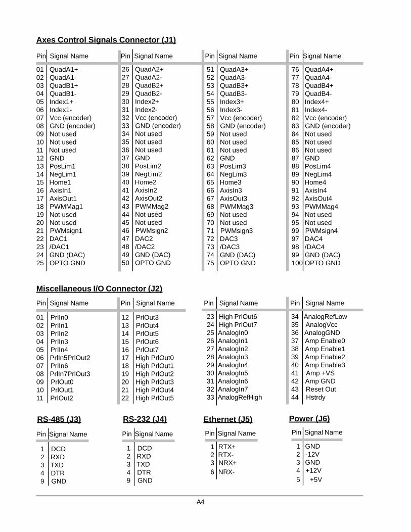
01 QuadA1+02 QuadA1-03 QuadB1+04 QuadB1-05 Index1+06 Index1-07 Vcc (encoder)08 GND (encoder)09 Not used10 Not used11 Not used12 GND13 PosLim114 NegLim115 Home116 AxisIn117 AxisOut118 PWMMag119 Not used20 Not used21 PWMsign122 DAC123 /DAC124 GND (DAC)25 OPTO GND
26 QuadA2+27 QuadA2-28 QuadB2+29 QuadB2-30 Index2+31 Index2-32 Vcc (encoder)33 GND (encoder)34 Not used35 Not used36 Not used37 GND38 PosLim239 NegLim240 Home241 AxisIn242 AxisOut243 PWMMag244 Not used45 Not used46 PWMsign247 DAC248 /DAC249 GND (DAC)50 OPTO GND
51 QuadA3+52 QuadA3-53 QuadB3+54 QuadB3-55 Index3+56 Index3-57 Vcc (encoder)58 GND (encoder)59 Not used60 Not used61 Not used62 GND63 PosLim364 NegLim365 Home366 AxisIn367 AxisOut368 PWMMag369 Not used70 Not used71 PWMsign372 DAC373 /DAC374 GND (DAC)75 OPTO GND
76 QuadA4+77 QuadA4-78 QuadB4+79 QuadB4-80 Index4+81 Index4-82 Vcc (encoder)83 GND (encoder)84 Not used85 Not used86 Not used87 GND88 PosLim489 NegLim490 Home491 AxisIn492 AxisOut493 PWMMag494 Not used95 Not used99 PWMsign497 DAC498 /DAC499 GND (DAC)100 OPTO GND
Pin Signal Name Pin Signal Name Pin Signal Name Pin Signal Name
Axes Control Signals Connector (J1)
01 PrlIn002 PrlIn103 PrlIn204 PrlIn305 PrlIn406 PrlIn5PrlOut207 PrlIn608 PrlIn7PrlOut309 PrlOut010 PrlOut111 PrlOut2
Miscellaneous I/O Connector (J2)
12 PrlOut313 PrlOut414 PrlOut515 PrlOut616 PrlOut717 High PrlOut018 High PrlOut119 High PrlOut220 High PrlOut321 High PrlOut422 High PrlOut5
Pin Signal Name Pin Signal Name
23 High PrlOut624 High PrlOut725 AnalogIn026 AnalogIn127 AnalogIn228 AnalogIn329 AnalogIn430 AnalogIn531 AnalogIn632 AnalogIn733 AnalogRefHigh
34 AnalogRefLow35 AnalogVcc36 AnalogGND37 Amp Enable038 Amp Enable139 Amp Enable240 Amp Enable341 Amp +VS42 Amp GND43 Reset Out44 Hstrdy
Pin Signal Name Pin Signal Name
1 DCD2 RXD3 TXD4 DTR9 GND
RS-485 (J3)
A4
Pin Signal Name
Ethernet (J5)
1 RTX+2 RTX-3 NRX+6 NRX-
Pin Signal Name
Power (J6)
1 GND2 -12V3 GND4 +12V5 +5V
RS-232 (J4)
Pin Signal Name
1 DCD2 RXD3 TXD4 DTR9 GND
Pin Signal Name

Environmental and Electrical Ratings
Dimensions 5.125” x 4.5” x 1.875” (130mm x 114mm x 48mm)Storage Temperature -40 °C to 125 °COperating Temperature 0 °C to 70 °C (an industrial version with an operating range of –40 °C
to 85 °C is also available)Power Consumption 2.5A @ 5V; 40mA @ -12V; 50mA @ +12VSupply Voltage Limits -0.3V to +7.0V; -15.0 to +15.0VSupply Voltage Operating Range 4.75V to 5.25V; -10.0V to -15.0V; +10.0V to +15.0VAnalog Output Range -10.0V to 10.0VAnalog Input Range 0.0V to 5.0V
Ordering information
AMCS-S - 0 - B -
A - analog output signalP - PWM output signal
1 - 1 axis controller2 - 2 axis controller4 - 4 axis controller
A5
W - wirelessI - expended I/OsD - built-in motor drives

Product Description
AMCS® [pronounced. a-maks] (Advanced Motion Con-trol Server) is an advanced server designated to controllbrushless DC servomotors with phase commutation. Itfeatures much more than a typical stand-alone motioncontroller with network connectivity.
AMCS is a full-featured web server with an embeddedmulti-axis motion controller in a very compact enclosure.It provides tremendous capabilities in network commu-nication, including the Internet, and at the same timefunctions independently through its own system soft-ware. The server can be accessed either through a HTMLgraphical interface or client applications. Devices incor-porating the AMCS can be controlled and monitored fromany place on the globe through the worldwide computernetwork. The controller is ideal for many automation ap-plications, such as robotic, machine tools, semiconduc-tor, scientific, medical, packaging, textile and industrial.
AMCS works in the Client-Server network architecture
Advanced Motion Control Server For Brushless DC Servomotors
AMCS-S-0x-BL
with the additional possibility of creating local sub-net-works, in case of a bigger number of control devices. Inthe latter case, the controllers work in a hierarchicalServer-Agent configuration. The server, unlike the agent,has the system software with more features and super-vises a group of agents. Both, the server and the agentare capable of directly controlling motor drives.
The motion controller harnesses the power of DSP andASIC chips to implement the motion control algorithms.It incorporates the advanced PID filter with velocity andacceleration feedforward, bias offset and 32-bit positionerror. The trajectory generator can create S-curve, trap-ezoidal, velocity contouring or electronic gearing motionprofiles. The axes can be programmed independently orsynchronously and can operate in open or closed servoloop modes. Motion functions support among others co-ordinated linear and circular interpolation, point-to-pointpositioning and contouring, backlash compensation, jog-ging and homing procedures.
A6
C i t oS y s t e m s

assists in a quick and easy way to set up and tune evencomplex electro-mechanical systems.
The controller is programmed by commonly used lan-guages and therefore does not require an advance levelof programming knowledge. Embedded interpreters makepossible writing control programs in G-code and HPGLstandards, C language and a language used in control-lers from the Galil company. They permit programmingof advanced motion trajectories realized by various kine-matical configurations.
The open software-hardware architecture allows for veryeasy system customization. Optionally, the controllercan be equipped with additional I/Os and wireless net-work communication.
Embedded Program Manager supervises all control pro-grams. It provides a multi-tasking environment for paral-lel programs execution, stopping and resuming. It alsoprovides information about currently loaded and runningprograms. The file system enables data and parameterspersistence.
AMCS is supported by the e-NetMotion™ andEasyMotion™ programs written in Java. The e-NetMotionclient application is a graphical interface allowing theserver and agents structure management, user accountadministration and facilitating access to the control de-vices depending on the user privilege level. Additionally,it provides a secure access to the system, secure trans-fer of data, programs and commands, and also remotemonitoring of the current status of all controllers in thenetwork. The EasyMotion graphical user interface
Server features:
Communication channels: 10/100 Mbps Base-T Ethernet port, and RS-232 and RS-485 serial portsHierarchical Client-Server-Agent configuration simplifying the network structure of control devicesSecure file transfer protocol (SFTP or SCP) for file and program transfersLogging to the server, data and command transfer using XML-RPC protocolThe HTTP web server allowing GUI development with HTMLData transfer using the XML standard and the TCL interpreterEmbedded mechanism of devices and user accounts administrationMulti-tasking Program Manager supervising control programsRemote monitoring of the current state of all controllers in the networkThe file system allowing for data and parameters persistence
Motion features:
Uses DSP and ASIC high speed dedicated motion processors in 1, 2 or 4 axes configurationSupports 2 or 3-phase brushless motors6-step (Hall based) or sinusoidal commutationIndependent or synchronous axes programmingOpen or closed servo loop operating modesAdvanced PID filter with velocity and acceleration feedforward, bias offset and 32-bit position errorAxis settled indicator and tracking window in addition to automatic motion error detectionChoice of S-curve, trapezoidal, velocity contouring or electronic gearing motion profilesAsymmetric acceleration and deceleration to custom program a trapezoidal motion profileVelocity and acceleration changes on-the-fly for trapezoidal and velocity contouring profilesPosition range from –2,147,483,648 to +2,147,483,647 countsVelocity range from -32,768 to +32,767 counts/sample with a resolution of 1/65,536 counts/sample invelocity contouring profile mode or from 0 to 32,767 counts/sample with a resolution of 1/65,536counts/sample in all other modesAcceleration and deceleration range from –32,768 to 32,767 counts/sample2 with a resolution of1/65,536 counts/sample2
Jerk range from 0 to 1 counts/sample3 with a resolution of 1/4,294,967,296 counts/sample3
Electronic gear ratio range from –32,768 to 32,767 (negative and positive direction)Programmable sample rate from 150 µsec to 3355 msec per axisSingle-ended or differential incremental encoder maximum rate up to 5.0 Mcounts/secMaximum parallel feedback device rate up to 160.0 Mcounts/secParallel feedback device word size: 16 bits3 Hall effect input signals per axis (TTL level) for brushless motors only
A7

A8
I/O features:
Dedicated opto-isolated inputs for over-travel limits, home sensor, and motor drive enable and fault hand-shaking operating at +5V, +12V, +24V or +48VOpto-isolated dedicated outputs for amplifier enable signals8 general purpose 10-bit analog inputs in range of 0 to 5.0V DC8 general purpose discrete TTL level input lines expandable to 256 inputs8 general purpose discrete output lines operating at TTL level, expandable to 128 outputs or paralled by 8opto-isolated signals capable of sinking or sourcing maximum 350mA at 50V
Commutation rate 10 kHz for 4 axes or 20 kHz for 1 and 2 axes+/-10V 16-bit DAC single-ended output signalPWM motor output signal of 10-bit resolution at 20 kHz (1 or 2 axes) or 10-bit resolution at 10 kHz (4 axes)- 50/50 PWM mode supports 2 or 3 phase motors, Sign/Magnitude PWM mode supports 2 phase motorsonly64 kByte dual-port memory buffer for real-time data and parameters storageTrace capabilities for system performance testing, servo-filter tuning and diagnostic purposesMotion functions support coordinated linear and circular interpolation, point-to-point positioning and contouring, backlash compensation, jogging, homing, etc.Status reporting for position, speed, errors and safetyProgrammable event triggers for monitoring elapsed time, motion complete, position, motion error, limitswitches and position wrap-around
Safety features:
Automatic motor shutdown on motion errorProgrammable watchdog timer in a range of 1 - 393 msecProgrammable software resetPower supply voltage monitor circuit to reset the systemExternal reset circuit
Software features:
High level programming with G-code and HPGL, C language interpreter and a language used in controllersfrom the Galil companyThe e-NetMotion™ (GUI) Java application facilitating full access to any device in the networkThe EasyMotion™ (GUI) Java application assists in a quick and easy way to set up and tune even complexelectro-mechanical systems
Options:
Wireless communicationExpanded number of motion axesExpanded number of I/Os

01 QuadA1+02 QuadA1-03 QuadB1+04 QuadB1-05 Index1+06 Index1-07 Vcc (encoder)08 GND (encoder)09 Hall1A10 Hall1B11 Hall1C12 GND (Hall)13 PosLim114 NegLim115 Home116 AxisIn117 AxisOut118 PWMMagA119 PWMMagB120 PWMMagC121 Not used22 DACA123 DACB124 GND (DAC)25 OPTO GND
26 QuadA2+27 QuadA2-28 QuadB2+29 QuadB2-30 Index2+31 Index2-32 Vcc (encoder)33 GND (encoder)34 Hall1A35 Hall2B36 Hall2C37 GND (Hall)38 PosLim239 NegLim240 Home241 AxisIn242 AxisOut243 PWMMagA244 PWMMagB245 PWMMagC246 Not used47 DACA248 DACB249 GND (DAC)50 OPTO GND
51 QuadA3+52 QuadA3-53 QuadB3+54 QuadB3-55 Index3+56 Index3-57 Vcc (encoder)58 GND (encoder)59 Hall1A60 Hall3B61 Hall3C62 GND (Hall)63 PosLim364 NegLim365 Home366 AxisIn367 AxisOut368 PWMMagA369 PWMMagB370 PWMMagC371 Not used72 DACA373 DACB374 GND (DAC)75 OPTO GND
76 QuadA4+77 QuadA4-78 QuadB4+79 QuadB4-80 Index4+81 Index4-82 Vcc (encoder)83 GND (encoder)84 Hall1A85 Hall4B86 Hall4C87 GND (Hall)88 PosLim489 NegLim490 Home491 AxisIn492 AxisOut493 PWMMagA494 PWMMagB495 PWMMagC499 Not used97 DACA498 DACB499 GND (DAC)100 OPTO GND
Pin Signal Name Pin Signal Name Pin Signal Name Pin Signal Name
Axes Control Signals Connector (J1)
01 PrlIn002 PrlIn103 PrlIn204 PrlIn305 PrlIn406 PrlIn5PrlOut207 PrlIn608 PrlIn7PrlOut309 PrlOut010 PrlOut111 PrlOut2
Miscellaneous I/O Connector (J2)
12 PrlOut313 PrlOut414 PrlOut515 PrlOut616 PrlOut717 High PrlOut018 High PrlOut119 High PrlOut220 High PrlOut321 High PrlOut422 High PrlOut5
Pin Signal Name Pin Signal Name
23 High PrlOut624 High PrlOut725 AnalogIn026 AnalogIn127 AnalogIn228 AnalogIn329 AnalogIn430 AnalogIn531 AnalogIn632 AnalogIn733 AnalogRefHigh
34 AnalogRefLow35 AnalogVcc36 AnalogGND37 Amp Enable038 Amp Enable139 Amp Enable240 Amp Enable341 Amp +VS42 Amp GND43 Reset Out44 Hstrdy
Pin Signal Name Pin Signal Name
1 DCD2 RXD3 TXD4 DTR9 GND
RS-485 (J3)
A9
Pin Signal Name
Ethernet (J5)
1 RTX+2 RTX-3 NRX+6 NRX-
Pin Signal Name
Power (J6)
1 GND2 -12V3 GND4 +12V5 +5V
RS-232 (J4)
Pin Signal Name
1 DCD2 RXD3 TXD4 DTR9 GND
Pin Signal Name

Environmental and Electrical Ratings
Dimensions 5.125” x 4.5” x 1.875” (130mm x 114mm x 48mm)Storage Temperature -40 °C to 125 °COperating Temperature 0 °C to 70 °C (an industrial version with an operating range of –40 °C
to 85 °C is also available)Power Consumption 2.5A @ 5V; 40mA @ -12V; 50mA @ +12VSupply Voltage Limits -0.3V to +7.0V; -15.0 to +15.0VSupply Voltage Operating Range 4.75V to 5.25V; -10.0V to -15.0V; +10.0V to +15.0VAnalog Output Range -10.0V to 10.0VAnalog Input Range 0.0V to 5.0V
Ordering information
AMCS-S - 0 - BL -
A - analog output signalP - PWM output signal
1 - 1 axis controller2 - 2 axis controller4 - 4 axis controller
A10
W - wirelessI - expended I/Os

Advanced Motion Control ServerFor Brush and Brushless Servomotors
AMCS-S-0x-B/BL
Product Description
AMCS® [pronounced. a-maks] (Advanced Motion Con-trol Server) is an advanced server designated to controllboth brush and brushless DC servomotors with phasecommutation. The user can designate which axes arebrushed and which are brushless. It features much morethan a typical stand-alone motion controller with net-work connectivity.
AMCS is a full-featured web server with an embeddedmulti-axis motion controller in a very compact enclosure.It provides tremendous capabilities in network commu-nication, including the Internet, and at the same timefunctions independently through its own system soft-ware. The server can be accessed either through a HTMLgraphical interface or client applications. Devices incor-porating the AMCS can be controlled and monitored fromany place on the globe through the worldwide computernetwork. The controller is ideal for many automation ap-plications, such as robotic, machine tools, semiconduc-tor, scientific, medical, packaging, textile and industrial.
AMCS works in the Client-Server network architecturewith the additional possibility of creating local sub-net-works, in case of a bigger number of control devices. Inthe latter case, the controllers work in a hierarchicalServer-Agent configuration. The server, unlike the agent,has the system software with more features and super-vises a group of agents. Both, the server and the agentare capable of directly controlling motor drives.
The motion controller harnesses the power of DSP andASIC chips to implement the motion control algorithms.It incorporates the advanced PID filter with velocity andacceleration feedforward, bias offset and 32-bit positionerror. The trajectory generator can create S-curve, trap-ezoidal, velocity contouring or electronic gearing motionprofiles. The axes can be programmed independently orsynchronously and can operate in open or closed servoloop modes. Motion functions support among others co-ordinated linear and circular interpolation, point-to-pointpositioning and contouring, backlash compensation, jog-
A11
C i t oS y s t e m s

Server features:
Communication channels: 10/100 Mbps Base-T Ethernet port, and RS-232 and RS-485 serial portsHierarchical Client-Server-Agent configuration simplifying the network structure of control devicesSecure file transfer protocol (SFTP or SCP) for file and program transfersLogging to the server, data and command transfer using XML-RPC protocolThe HTTP web server allowing GUI development with HTMLData transfer using the XML standard and the TCL interpreterEmbedded mechanism of devices and user accounts administrationMulti-tasking Program Manager supervising control programsRemote monitoring of the current state of all controllers in the networkThe file system allowing for data and parameters persistence
Motion features:
Uses DSP and ASIC high speed dedicated motion processors in 1, 2 or 4 axes configurationSupports single phase brush and 2 or 3- phase brushless motors6-step (Hall based) or sinusoidal commutation of brushless motors onlyIndependent or synchronous axes programmingOpen or closed servo loop operating modesAdvanced PID filter with velocity and acceleration feedforward, bias offset and 32-bit position errorAxis settled indicator and tracking window in addition to automatic motion error detectionChoice of S-curve, trapezoidal, velocity contouring or electronic gearing motion profilesAsymmetric acceleration and deceleration to custom program a trapezoidal motion profileVelocity and acceleration changes on-the-fly for trapezoidal and velocity contouring profilesPosition range from –2,147,483,648 to +2,147,483,647 countsVelocity range from -32,768 to +32,767 counts/sample with a resolution of 1/65,536 counts/sample invelocity contouring profile mode or from 0 to 32,767 counts/sample with a resolution of 1/65,536counts/sample in all other modesAcceleration and deceleration range from –32,768 to 32,767 counts/sample2 with a resolution of1/65,536 counts/sample2
Jerk range from 0 to 1 counts/sample3 with a resolution of 1/4,294,967,296 counts/sample3
Electronic gear ratio range from –32,768 to 32,767 (negative and positive direction)Programmable sample rate from 150 µsec to 3355 msec per axisSingle-ended or differential incremental encoder maximum rate up to 5.0 Mcounts/secMaximum parallel feedback device rate up to 160.0 Mcounts/sec
The EasyMotion graphical user interfaceassists in a quickand easy way to set up and tune even complex electro-mechanical systems.
The controller is programmed by commonly used lan-guages and therefore does not require an advance levelof programming knowledge. Embedded interpreters makepossible writing control programs in G-code and HPGLstandards, C language and a language used in control-lers from the Galil company. They permit programmingof advanced motion trajectories realized by various kine-matical configurations.
The open software-hardware architecture allows for veryeasy system customization. Optionally, the controllercan be equipped with additional I/Os, wireless networkcommunication and integrated drives for brush type DCservomotors.
ging and homing procedures.
Embedded Program Manager supervises all control pro-grams. It provides a multi-tasking environment for paral-lel programs execution, stopping and resuming. It alsoprovides information about currently loaded and runningprograms. The file system enables data and parameterspersistence.
AMCS is supported by the e-NetMotion™ andEasyMotion™ programs written in Java. The e-NetMotionclient application is a graphical interface allowing theserver and agents structure management, user accountadministration and facilitating access to the control de-vices depending on the user privilege level. Additionally,it provides a secure access to the system, secure trans-fer of data, programs and commands, and also remotemonitoring of the current status of all controllers in thenetwork.
A12

A13
I/O features:
Dedicated opto-isolated inputs for over-travel limits, home sensor, and motor drive enable and fault hand-shaking operating at +5V, +12V, +24V or +48VOpto-isolated dedicated outputs for amplifier enable signals8 general purpose 10-bit analog inputs in range of 0 to 5.0V DC8 general purpose discrete TTL level input lines expandable to 256 inputs8 general purpose discrete output lines operating at TTL level, expandable to 128 outputs or paralled by 8opto-isolated signals capable of sinking or sourcing maximum 350mA at 50V
Parallel feedback device word size: 16 bits3 Hall effect input signals per axis (TTL level) for brushless motors onlyCommutation rate 10 kHz for 4 axes or 20 kHz for 2 axes+/-10V 16-bit DAC differential or single-ended output signalPWM motor output signal of 10-bit resolution at 20 kHz - 50/50 PWM mode supports 1, 2 or 3 phasemotors, Sign/Magnitude PWM mode supports 1 or 2 phase motors only64 kByte dual-port memory buffer for real-time data and parameters storageTrace capabilities for system performance testing, servo-filter tuning and diagnostic purposesMotion functions support coordinated linear and circular interpolation, point-to-point positioning and contouring, backlash compensation, jogging, homing, etc.Status reporting for position, speed, errors and safetyProgrammable event triggers for monitoring elapsed time, motion complete, position, motion error, limitswitches and position wrap-around
Safety features:
Automatic motor shutdown on motion errorProgrammable watchdog timer in a range of 1 - 393 msecProgrammable software resetPower supply voltage monitor circuit to reset the systemExternal reset circuit
Software features:
High level programming with G-code and HPGL, C language interpreter and a language used in controllersfrom the Galil companyThe e-NetMotion™ (GUI) Java application facilitating full access to any device in the networkThe EasyMotion™ (GUI) Java application assists in a quick and easy way to set up and tune even complexelectro-mechanical systems
Options:
Wireless communicationExpanded number of motion axesExpanded number of I/Os

01 QuadA1+02 QuadA1-03 QuadB1+04 QuadB1-05 Index1+06 Index1-07 Vcc (encoder)08 GND (encoder)09 Hall1A*10 Hall1B*11 Hall1C*12 GND (Hall)13 PosLim114 NegLim115 Home116 AxisIn117 AxisOut118 PWMMagA119 PWMMagB1*20 PWMMagC1*21 Not used22 DACA123 DACB1*24 GND (DAC)25 OPTO GND
26 QuadA2+27 QuadA2-28 QuadB2+29 QuadB2-30 Index2+31 Index2-32 Vcc (encoder)33 GND (encoder)34 Hall2A*35 Hall2B*36 Hall2C*37 GND (Hall)38 PosLim239 NegLim240 Home241 AxisIn242 AxisOut243 PWMMagA244 PWMMagB2*45 PWMMagC2*46 Not used47 DACA248 DACB2*49 GND (DAC)50 OPTO GND
51 QuadA3+52 QuadA3-53 QuadB3+54 QuadB3-55 Index3+56 Index3-57 Vcc (encoder)58 GND (encoder)59 Hall3A*60 Hall3B*61 Hall3C*62 GND (Hall)63 PosLim364 NegLim365 Home366 AxisIn367 AxisOut368 PWMMagA369 PWMMagB3*70 PWMMagC3*71 Not used72 DACA373 DACB3*74 GND (DAC)75 OPTO GND
76 QuadA4+77 QuadA4-78 QuadB4+79 QuadB4-80 Index4+81 Index4-82 Vcc (encoder)83 GND (encoder)84 Hall4A*85 Hall4B*86 Hall4C*87 GND (Hall)88 PosLim489 NegLim490 Home491 AxisIn492 AxisOut493 PWMMagA494 PWMMagB4*95 PWMMagC4*99 Not used97 DACA498 DACB4*99 GND (DAC)100 OPTO GND
Pin Signal Name Pin Signal Name Pin Signal Name Pin Signal Name
Axes Control Signals Connector (J1)
01 PrlIn002 PrlIn103 PrlIn204 PrlIn305 PrlIn406 PrlIn5PrlOut207 PrlIn608 PrlIn7PrlOut309 PrlOut010 PrlOut111 PrlOut2
Miscellaneous I/O Connector (J2)
12 PrlOut313 PrlOut414 PrlOut515 PrlOut616 PrlOut717 High PrlOut018 High PrlOut119 High PrlOut220 High PrlOut321 High PrlOut422 High PrlOut5
Pin Signal Name Pin Signal Name
23 High PrlOut624 High PrlOut725 AnalogIn026 AnalogIn127 AnalogIn228 AnalogIn329 AnalogIn430 AnalogIn531 AnalogIn632 AnalogIn733 AnalogRefHigh
34 AnalogRefLow35 AnalogVcc36 AnalogGND37 Amp Enable038 Amp Enable139 Amp Enable240 Amp Enable341 Amp +VS42 Amp GND43 Reset Out44 Hstrdy
Pin Signal Name Pin Signal Name
1 DCD2 RXD3 TXD4 DTR9 GND
RS-485 (J3)
A14
Pin Signal Name
Ethernet (J5)
1 RTX+2 RTX-3 NRX+6 NRX-
Pin Signal Name
Power (J6)
1 GND2 -12V3 GND4 +12V5 +5V
RS-232 (J4)
Pin Signal Name
1 DCD2 RXD3 TXD4 DTR9 GND
Pin Signal Name
* - depends on user axes designation

Environmental and Electrical Ratings
Dimensions 5.125” x 4.5” x 1.875” (130mm x 114mm x 48mm)Storage Temperature -40 °C to 125 °COperating Temperature 0 °C to 70 °C (an industrial version with an operating range of –40 °C
to 85 °C is also available)Power Consumption 2.5A @ 5V; 40mA @ -12V; 50mA @ +12VSupply Voltage Limits -0.3V to +7.0V; -15.0 to +15.0VSupply Voltage Operating Range 4.75V to 5.25V; -10.0V to -15.0V; +10.0V to +15.0VAnalog Output Range -10.0V to 10.0VAnalog Input Range 0.0V to 5.0V
Ordering information
AMCS-S - 0 - BL/B -
A - analog output signalP - PWM output signal
2 - 2 axis controller4 - 4 axis controller
A15
W - wirelessI - expended I/Os

Product Description
AMCS® [pronounced. a-maks] (Advanced Motion Con-trol Server) is an advanced server designated to controllmicrostepping motors. It features much more than a typi-cal stand-alone motion controller with network connec-tivity.
AMCS is a full-featured web server with an embeddedmulti-axis motion controller in a very compact enclosure.It provides tremendous capabilities in network commu-nication, including the Internet, and at the same timefunctions independently through its own system soft-ware. The server can be accessed either through a HTMLgraphical interface or client applications. Devices incor-porating the AMCS can be controlled and monitored fromany place on the globe through the worldwide computernetwork. The controller is ideal for many automation ap-plications, such as robotic, machine tools, semiconduc-tor, scientific, medical, packaging, textile and industrial.
AMCS works in the Client-Server network architecture
Advanced Motion Control Server For Microstepping Motors
AMCS-S-0x-MS
with the additional possibility of creating local sub-net-works, in case of a bigger number of control devices. Inthe latter case, the controllers work in a hierarchicalServer-Agent configuration. The server, unlike the agent,has the system software with more features and super-vises a group of agents. Both, the server and the agentare capable of directly controlling motor drives.
The motion controller harnesses the power of DSP andASIC chips to implement the motion control algorithms.It incorporates the advanced PID filter with velocity andacceleration feedforward, bias offset and 32-bit positionerror. The trajectory generator can create S-curve, trap-ezoidal, velocity contouring or electronic gearing motionprofiles. The axes can be programmed independently orsynchronously and can operate in open or closed servoloop modes. Motion functions support among others co-ordinated linear and circular interpolation, point-to-pointpositioning and contouring, backlash compensation, jog-ging and homing procedures.
A16
C i t oS y s t e m s

assists in a quick and easy way to set up and tune evencomplex electro-mechanical systems.
The controller is programmed by commonly used lan-guages and therefore does not require an advance levelof programming knowledge. Embedded interpreters makepossible writing control programs in G-code and HPGLstandards, C language and a language used in control-lers from the Galil company. They permit programmingof advanced motion trajectories realized by various kine-matical configurations.
The open software-hardware architecture allows for veryeasy system customization. Optionally, the controllercan be equipped with additional I/Os and wireless net-work communication.
Embedded Program Manager supervises all control pro-grams. It provides a multi-tasking environment for paral-lel programs execution, stopping and resuming. It alsoprovides information about currently loaded and runningprograms. The file system enables data and parameterspersistence.
AMCS is supported by the e-NetMotion™ andEasyMotion™ programs written in Java. The e-NetMotionclient application is a graphical interface allowing theserver and agents structure management, user accountadministration and facilitating access to the control de-vices depending on the user privilege level. Additionally,it provides a secure access to the system, secure trans-fer of data, programs and commands, and also remotemonitoring of the current status of all controllers in thenetwork. The EasyMotion graphical user interface
Server features:
Communication channels: 10/100 Mbps Base-T Ethernet port, and RS-232 and RS-485 serial portsHierarchical Client-Server-Agent configuration simplifying the network structure of control devicesSecure file transfer protocol (SFTP or SCP) for file and program transfersLogging to the server, data and command transfer using XML-RPC protocolThe HTTP web server allowing GUI development with HTMLData transfer using the XML standard and the TCL interpreterEmbedded mechanism of devices and user accounts administrationMulti-tasking Program Manager supervising control programsRemote monitoring of the current state of all controllers in the networkThe file system allowing for data and parameters persistence
Motion features:
Uses DSP and ASIC high speed dedicated motion processors in 1, 2 or 4 axes configurationSupports 2 or 3-phase stepping motorsProgrammable microstepping rate from 1 to 256 counts per full stepIndependent or synchronous axes programmingOpen loop operating moderChoice of S-curve, trapezoidal, velocity contouring or electronic gearing motion profilesAsymmetric acceleration and deceleration to custom program a trapezoidal motion profileVelocity and acceleration changes on-the-fly for trapezoidal and velocity contouring profilesPosition range from –2,147,483,648 to +2,147,483,647 countsVelocity range from -32,768 to +32,767 counts/sample with a resolution of 1/65,536 counts/sample invelocity contouring profile mode or from 0 to 32,767 counts/sample with a resolution of 1/65,536counts/sample in all other modesAcceleration and deceleration range from –32,768 to 32,767 counts/sample2 with a resolution of1/65,536 counts/sample2
Jerk range from 0 to 1 counts/sample3 with a resolution of 1/4,294,967,296 counts/sample3
Electronic gear ratio range from –32,768 to 32,767 (negative and positive direction)Programmable sample rate from 150 µsec to 3355 msec per axisSingle-ended or differential incremental encoder maximum rate up to 5.0 Mcounts/secMaximum parallel feedback device rate up to 160.0 Mcounts/secParallel feedback device word size: 16 bitsCommutation rate 10 kHz for 4 axes or 20 kHz for 1 and 2 axes+/-10V 16-bit DAC single-ended output signalPWM motor output signal of 8-bit resolution at 80 kHz or 10-bit at 10 kHz
A17

A18
I/O features:
Dedicated opto-isolated inputs for over-travel limits, home sensor, and motor drive enable and fault hand-shaking operating at +5V, +12V, +24V or +48VOpto-isolated dedicated outputs for amplifier enable signals8 general purpose 10-bit analog inputs in range of 0 to 5.0V DC8 general purpose discrete TTL level input lines expandable to 256 inputs8 general purpose discrete output lines operating at TTL level, expandable to 128 outputs or paralled by 8opto-isolated signals capable of sinking or sourcing maximum 350mA at 50V
64 kByte dual-port memory buffer for real-time data and parameters storageTrace capabilities for system performance testing, servo-filter tuning and diagnostic purposesMotion functions support coordinated linear and circular interpolation, point-to-point positioning and contouring, backlash compensation, jogging, homing, etc.Status reporting for position, speed, errors and safetyProgrammable event triggers for monitoring elapsed time, motion complete, position, motion error, limitswitches and position wrap-around
Safety features:
Automatic motor shutdown on motion errorProgrammable watchdog timer in a range of 1 - 393 msecProgrammable software resetPower supply voltage monitor circuit to reset the systemExternal reset circuit
Software features:
High level programming with G-code and HPGL, C language interpreter and a language used in controllersfrom the Galil companyThe e-NetMotion™ (GUI) Java application facilitating full access to any device in the networkThe EasyMotion™ (GUI) Java application assists in a quick and easy way to set up and tune even complexelectro-mechanical systems
Options:
Wireless communicationExpanded number of motion axesExpanded number of I/Os

01 QuadA1+02 QuadA1-03 QuadB1+04 QuadB1-05 Index1+06 Index1-07 Vcc (encoder)08 GND (encoder)09 Not used10 Not used11 Not used12 GND13 PosLim114 NegLim115 Home116 AxisIn117 AxisOut118 PWMMagA119 PWMMagB120 PWMSignA121 PWMSignB122 DACA123 DACB124 GND (DAC)25 OPTO GND
26 QuadA2+27 QuadA2-28 QuadB2+29 QuadB2-30 Index2+31 Index2-32 Vcc (encoder)33 GND (encoder)34 Not used35 Not used36 Not used37 GND38 PosLim239 NegLim240 Home241 AxisIn242 AxisOut243 PWMMagA244 PWMMagB245 PWMSignA246 PWMSignB247 DACA248 DACB249 GND (DAC)50 OPTO GND
51 QuadA3+52 QuadA3-53 QuadB3+54 QuadB3-55 Index3+56 Index3-57 Vcc (encoder)58 GND (encoder)59 Not used60 Not used61 Not used62 GND63 PosLim364 NegLim365 Home366 AxisIn367 AxisOut368 PWMMagA369 PWMMagB370 PWMSignA371 PWMSignB372 DACA373 DACB374 GND (DAC)75 OPTO GND
76 QuadA4+77 QuadA4-78 QuadB4+79 QuadB4-80 Index4+81 Index4-82 Vcc (encoder)83 GND (encoder)84 Not used85 Not used86 Not used87 GND88 PosLim489 NegLim490 Home491 AxisIn492 AxisOut493 PWMMagA494 PWMMagB495 PWMSignA499 PWMSignB497 DACA498 DACB499 GND (DAC)100 OPTO GND
Pin Signal Name Pin Signal Name Pin Signal Name Pin Signal Name
Axes Control Signals Connector (J1)
01 PrlIn002 PrlIn103 PrlIn204 PrlIn305 PrlIn406 PrlIn5PrlOut207 PrlIn608 PrlIn7PrlOut309 PrlOut010 PrlOut111 PrlOut2
Miscellaneous I/O Connector (J2)
12 PrlOut313 PrlOut414 PrlOut515 PrlOut616 PrlOut717 High PrlOut018 High PrlOut119 High PrlOut220 High PrlOut321 High PrlOut422 High PrlOut5
Pin Signal Name Pin Signal Name
23 High PrlOut624 High PrlOut725 AnalogIn026 AnalogIn127 AnalogIn228 AnalogIn329 AnalogIn430 AnalogIn531 AnalogIn632 AnalogIn733 AnalogRefHigh
34 AnalogRefLow35 AnalogVcc36 AnalogGND37 Amp Enable038 Amp Enable139 Amp Enable240 Amp Enable341 Amp +VS42 Amp GND43 Reset Out44 Hstrdy
Pin Signal Name Pin Signal Name
1 DCD2 RXD3 TXD4 DTR9 GND
RS-485 (J3)
A19
Pin Signal Name
Ethernet (J5)
1 RTX+2 RTX-3 NRX+6 NRX-
Pin Signal Name
Power (J6)
1 GND2 -12V3 GND4 +12V5 +5V
RS-232 (J4)
Pin Signal Name
1 DCD2 RXD3 TXD4 DTR9 GND
Pin Signal Name
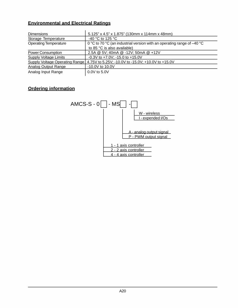
Environmental and Electrical Ratings
Dimensions 5.125” x 4.5” x 1.875” (130mm x 114mm x 48mm)Storage Temperature -40 °C to 125 °COperating Temperature 0 °C to 70 °C (an industrial version with an operating range of –40 °C
to 85 °C is also available)Power Consumption 2.5A @ 5V; 40mA @ -12V; 50mA @ +12VSupply Voltage Limits -0.3V to +7.0V; -15.0 to +15.0VSupply Voltage Operating Range 4.75V to 5.25V; -10.0V to -15.0V; +10.0V to +15.0VAnalog Output Range -10.0V to 10.0VAnalog Input Range 0.0V to 5.0V
Ordering information
AMCS-S - 0 - MS -
A - analog output signalP - PWM output signal
1 - 1 axis controller2 - 2 axis controller4 - 4 axis controller
A20
W - wirelessI - expended I/Os

Product Description
AMCS® [pronounced. a-maks] (Advanced Motion Con-trol Server) is an advanced server designated to controllstepper motors. It features much more than a typicalstand-alone motion controller with network connectivity.
AMCS is a full-featured web server with an embeddedmulti-axis motion controller in a very compact enclosure.It provides tremendous capabilities in network commu-nication, including the Internet, and at the same timefunctions independently through its own system soft-ware. The server can be accessed either through a HTMLgraphical interface or client applications. Devices incor-porating the AMCS can be controlled and monitored fromany place on the globe through the worldwide computernetwork. The controller is ideal for many automation ap-plications, such as robotic, machine tools, semiconduc-tor, scientific, medical, packaging, textile and industrial.
AMCS works in the Client-Server network architecturewith the additional possibility of creating local sub-net-
Advanced Motion Control Server For Stepper Motors
AMCS-S-0x-S
works, in case of a bigger number of control devices. Inthe latter case, the controllers work in a hierarchicalServer-Agent configuration. The server, unlike the agent,has the system software with more features and super-vises a group of agents. Both, the server and the agentare capable of directly controlling motor drives.
The motion controller harnesses the power of DSP andASIC chips to implement the motion control algorithms.It incorporates the advanced PID filter with velocity andacceleration feedforward, bias offset and 32-bit positionerror. The trajectory generator can create S-curve, trap-ezoidal, velocity contouring or electronic gearing motionprofiles. The axes can be programmed independently orsynchronously and can operate in open or closed servoloop modes. Motion functions support among others co-ordinated linear and circular interpolation, point-to-pointpositioning and contouring, backlash compensation, jog-ging and homing procedures.
A21
C i t oS y s t e m s

assists in a quick and easy way to set up and tune evencomplex electro-mechanical systems.
The controller is programmed by commonly used lan-guages and therefore does not require an advance levelof programming knowledge. Embedded interpreters makepossible writing control programs in G-code and HPGLstandards, C language and a language used in control-lers from the Galil company. They permit programmingof advanced motion trajectories realized by various kine-matical configurations.
The open software-hardware architecture allows for veryeasy system customization. Optionally, the controllercan be equipped with additional I/Os, wireless networkcommunication and integrated drives for stepper motors.
Embedded Program Manager supervises all control pro-grams. It provides a multi-tasking environment for paral-lel programs execution, stopping and resuming. It alsoprovides information about currently loaded and runningprograms. The file system enables data and parameterspersistence.
AMCS is supported by the e-NetMotion™ andEasyMotion™ programs written in Java. The e-NetMotionclient application is a graphical interface allowing theserver and agents structure management, user accountadministration and facilitating access to the control de-vices depending on the user privilege level. Additionally,it provides a secure access to the system, secure trans-fer of data, programs and commands, and also remotemonitoring of the current status of all controllers in thenetwork. The EasyMotion graphical user interface
Server features:
Communication channels: 10/100 Mbps Base-T Ethernet port, and RS-232 and RS-485 serial portsHierarchical Client-Server-Agent configuration simplifying the network structure of control devicesSecure file transfer protocol (SFTP or SCP) for file and program transfersLogging to the server, data and command transfer using XML-RPC protocolThe HTTP web server allowing GUI development with HTMLData transfer using the XML standard and the TCL interpreterEmbedded mechanism of devices and user accounts administrationMulti-tasking Program Manager supervising control programsRemote monitoring of the current state of all controllers in the networkThe file system allowing for data and parameters persistence
Motion features:
Uses DSP and ASIC high speed dedicated motion processors in 1, 2 or 4 axes configurationIndependent or synchronous axes programmingOpen loop or stall detection with encoder feedback operating modesChoice of S-curve, trapezoidal, velocity contouring or electronic gearing motion profilesAsymmetric acceleration and deceleration to custom program a trapezoidal motion profileVelocity and acceleration changes on-the-fly for trapezoidal and velocity contouring profilesPosition range from –2,147,483,648 to +2,147,483,647 countsVelocity range from -32,768 to +32,767 counts/sample with a resolution of 1/65,536 counts/sample invelocity contouring profile mode or from 0 to 32,767 counts/sample with a resolution of 1/65,536counts/sample in all other modesAcceleration and deceleration range from –32,768 to 32,767 counts/sample2 with a resolution of1/65,536 counts/sample2
Jerk range from 0 to 1 counts/sample3 with a resolution of 1/4,294,967,296 counts/sample3
Electronic gear ratio range from –32,768 to 32,767 (negative and positive direction)Programmable sample rate from 150 µsec to 3355 msec per axisSingle-ended or differential incremental encoder maximum rate up to 5.0 Mcounts/secMaximum parallel feedback device rate up to 160.0 Mcounts/secParallel feedback device word size: 16 bitsPulse and direction motor output up to 4.98 M-pulses/sec64 kByte dual-port memory buffer for real-time data and parameters storageTrace capabilities for system performance testing, servo-filter tuning and diagnostic purposesMotion functions support coordinated linear and circular interpolation, point-to-point positioning and contouring, backlash compensation, jogging, homing, etc.
A22

A23
I/O features:
Dedicated opto-isolated inputs for over-travel limits, home sensor, and motor drive enable and fault hand-shaking operating at +5V, +12V, +24V or +48VOpto-isolated dedicated outputs for amplifier enable signals8 general purpose 10-bit analog inputs in range of 0 to 5.0V DC8 general purpose discrete TTL level input lines expandable to 256 inputs8 general purpose discrete output lines operating at TTL level, expandable to 128 outputs or paralled by 8opto-isolated signals capable of sinking or sourcing maximum 350mA at 50V
Safety features:
Automatic motor shutdown on motion errorProgrammable watchdog timer in a range of 1 - 393 msecProgrammable software resetPower supply voltage monitor circuit to reset the systemExternal reset circuit
Software features:
High level programming with G-code and HPGL, C language interpreter and a language used in controllersfrom the Galil companyThe e-NetMotion™ (GUI) Java application facilitating full access to any device in the networkThe EasyMotion™ (GUI) Java application assists in a quick and easy way to set up and tune even complexelectro-mechanical systems
Options:
Wireless communicationExpanded number of motion axesExpanded number of I/OsIntegrated stepper motor drives
Status reporting for position, speed, errors and safetyProgrammable event triggers for monitoring elapsed time, motion complete, position, motion error, limitswitches and position wrap-around

01 QuadA1+02 QuadA1-03 QuadB1+04 QuadB1-05 Index1+06 Index1-07 Vcc (encoder)08 GND (encoder)09 Not used10 Not used11 Not used12 GND13 PosLim114 NegLim115 Home116 AxisIn117 AxisOut118 Pulse119 Not used20 Not used21 Direction122 Not used23 Not used24 GND25 OPTO GND
26 QuadA2+27 QuadA2-28 QuadB2+29 QuadB2-30 Index2+31 Index2-32 Vcc (encoder)33 GND (encoder)34 Not used35 Not used36 Not used37 GND38 PosLim239 NegLim240 Home241 AxisIn242 AxisOut243 Pulse244 Not used45 Not used46 Direction247 Not used48 Not used49 GND50 OPTO GND
51 QuadA3+52 QuadA3-53 QuadB3+54 QuadB3-55 Index3+56 Index3-57 Vcc (encoder)58 GND (encoder)59 Not used60 Not used61 Not used62 GND63 PosLim364 NegLim365 Home366 AxisIn367 AxisOut368 Pulse369 Not used70 Not used71 Direction372 Not used73 Not used74 GND75 OPTO GND
76 QuadA4+77 QuadA4-78 QuadB4+79 QuadB4-80 Index4+81 Index4-82 Vcc (encoder)83 GND (encoder)84 Not used85 Not used86 Not used87 GND88 PosLim489 NegLim490 Home491 AxisIn492 AxisOut493 Pulse494 Not used95 Not used99 Direction497 Not used98 Not used99 GND100 OPTO GND
Pin Signal Name Pin Signal Name Pin Signal Name Pin Signal Name
Axes Control Signals Connector (J1)
01 PrlIn002 PrlIn103 PrlIn204 PrlIn305 PrlIn406 PrlIn5PrlOut207 PrlIn608 PrlIn7PrlOut309 PrlOut010 PrlOut111 PrlOut2
Miscellaneous I/O Connector (J2)
12 PrlOut313 PrlOut414 PrlOut515 PrlOut616 PrlOut717 High PrlOut018 High PrlOut119 High PrlOut220 High PrlOut321 High PrlOut422 High PrlOut5
Pin Signal Name Pin Signal Name
23 High PrlOut624 High PrlOut725 AnalogIn026 AnalogIn127 AnalogIn228 AnalogIn329 AnalogIn430 AnalogIn531 AnalogIn632 AnalogIn733 AnalogRefHigh
34 AnalogRefLow35 AnalogVcc36 AnalogGND37 Amp Enable038 Amp Enable139 Amp Enable240 Amp Enable341 Amp +VS42 Amp GND43 Reset Out44 Hstrdy
Pin Signal Name Pin Signal Name
1 DCD2 RXD3 TXD4 DTR9 GND
RS-485 (J3)
A24
Pin Signal Name
Ethernet (J5)
1 RTX+2 RTX-3 NRX+6 NRX-
Pin Signal Name
Power (J6)
1 GND2 -12V3 GND4 +12V5 +5V
RS-232 (J4)
Pin Signal Name
1 DCD2 RXD3 TXD4 DTR9 GND
Pin Signal Name
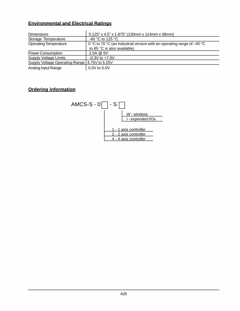
Environmental and Electrical Ratings
Dimensions 5.125” x 4.5” x 1.875” (130mm x 114mm x 48mm)Storage Temperature -40 °C to 125 °COperating Temperature 0 °C to 70 °C (an industrial version with an operating range of –40 °C
to 85 °C is also available)Power Consumption 2.5A @ 5VSupply Voltage Limits -0.3V to +7.0VSupply Voltage Operating Range 4.75V to 5.25VAnalog Input Range 0.0V to 5.0V
Ordering information
AMCS-S - 0 - S
1 - 1 axis controller2 - 2 axis controller4 - 4 axis controller
A25
W - wirelessI - expended I/Os

Product Description
The PCI-bus cards of the Millennium series are highperformance feature-rich multi axis motion controllers.The 3mi-0x-B model implements the Navigator MC21xxseries chipsets - dedicated motion processors to con-trol brush or brushless servomotors. These controllersharness the power of the Navigator high-speed DSP chipand incorporate ASIC and surface mount technologies.The Millennium controllers are available in configurationsof 1, 2 or 4 axes.
The DSP unit provides S-curve, trapezoidal, velocitycontouring and electronic gearing profiling modes forAnalog or PWM signal output. Onboard memory al-lows designers to capture on-the-fly motion data foranalyzing system performance, tuning servo filters anddiagnostic purposes. Motion trajectory segments canbe blended into continuous motion path in the velocitymode.
The boards interface to external components via a 100pin high density connector providing motor outputs andreading pulsed encoder (incremental or absolute), limitswitches and home indicator input signals. They arecapable of handling eight analog inputs and eight user-defined discrete I/Os.
The cards are supported by C-MotionPlus™ andCyberMotion™ - extensive C-language software librar-ies and Windows and Linux drivers, which allow devel-opment of any motion control application. EasyMotion™,a GUI application package with the industry’s first everMotionWizard, assists in a quick and easy way to setup and tune even complex electro-mechanical systems.
The boards can be used in a variety of industries, suchas robotic, machine tool, semiconductor, medical, foodprocessing, textile and many others.
PCI-bus Millennium Series Motion Controller BoardFor Brush Servomotors
3mi-0x-B
A26
C i t oS y s t e m s

Features:
Uses DSP and ASIC high speed dedicated motion processors in 1, 2 or 4 axes configurationIndependent or synchronous axes programmingOpen or closed servo loop operating modesAdvanced PID filter with velocity and acceleration feedforward, bias offset and 32-bit position errorAxis settled indicator and tracking window in addition to automatic motion error detectionChoice of S-curve, trapezoidal, velocity contouring or electronic gearing motion profilesAsymmetric acceleration and deceleration to custom program a trapezoidal motion profileVelocity and acceleration changes on-the-fly for trapezoidal and velocity contouring profilesPosition range from –2,147,483,648 to +2,147,483,647 countsVelocity range from -32,768 to +32,767 counts/sample with a resolution of 1/65,536 counts/sample invelocity contouring profile mode or from 0 to 32,767 counts/sample with a resolution of 1/65,536counts/sample in all other modesAcceleration and deceleration range from –32,768 to 32,767 counts/sample2 with a resolution of1/65,536 counts/sample2
Jerk range from 0 to 1 counts/sample3 with a resolution of 1/4,294,967,296 counts/sample3
Electronic gear ratio range from –32,768 to 32,767 (negative and positive direction)Programmable sample rate from 100 µsec to 3355 msec per axisSingle-ended or differential incremental encoder maximum rate up to 5.0 Mcounts/secMaximum parallel feedback device rate up to 160.0 Mcounts/secParallel feedback device word size: 16 bits+/-10V differential 16-bit DAC output signalPWM motor output signal of 10-bit resolution at 20 kHzOn-board 64 kByte dual-port memory buffer for data and parameters storagePCI-bus communication interfaceOpto-isolated dedicated inputs for two-directional travel limit switches, home indicator and fault signaloperating at +5V, +12V, +24V or +48V8 general purpose discrete TTL level input lines8 uncommitted discrete output lines operating at TTL level, expandable to 128 outputs or opto-isolatedcapable of sinking or sourcing maximum 350 mA at 50V8 general purpose 10-bit analog inputs in range of 0 to 5.0 V dcAutomatic motor shutdown on motion errorProgrammable host interruptsTrace capabilities for system performance testing, servo-filter tuning and diagnostic purposesSoftware functions support coordinated linear and circular interpolation, point-to-point positioning andcontouring, backlash compensation, jogging, homing, etc.Status reporting for position, speed and errorsInfinite number of linear and arc segments for smooth motionProgrammable event triggers for monitoring elapsed time, motion complete, position, motion error, limitswitches and position wrap-around
A27

01 QuadA1+02 QuadA1-03 QuadB1+04 QuadB1-05 Index1+06 Index1-07 Vcc (encoder)08 GND (encoder)09 Not used10 Not used11 Not used12 GND13 PosLim114 NegLim115 Home116 AxisIn117 AxisOut118 PWMMag119 Not used20 Not used21 PWMsign122 DAC123 /DAC124 GND (DAC)25 OPTO GND
26 QuadA2+27 QuadA2-28 QuadB2+29 QuadB2-30 Index2+31 Index2-32 Vcc (encoder)33 GND (encoder)34 Not used35 Not used36 Not used37 GND38 PosLim239 NegLim240 Home241 AxisIn242 AxisOut243 PWMMag244 Not used45 Not used46 PWMsign247 DAC248 /DAC249 GND (DAC)50 OPTO GND
51 QuadA3+52 QuadA3-53 QuadB3+54 QuadB3-55 Index3+56 Index3-57 Vcc (encoder)58 GND (encoder)59 Not used60 Not used61 Not used62 GND63 PosLim364 NegLim365 Home366 AxisIn367 AxisOut368 PWMMag369 Not used70 Not used71 PWMsign372 DAC373 /DAC374 GND (DAC)75 OPTO GND
76 QuadA4+77 QuadA4-78 QuadB4+79 QuadB4-80 Index4+81 Index4-82 Vcc (encoder)83 GND (encoder)84 Not used85 Not used86 Not used87 GND88 PosLim489 NegLim490 Home491 AxisIn492 AxisOut493 PWMMag494 Not used95 Not used99 PWMsign497 DAC498 /DAC499 GND (DAC)100 OPTO GND
Pin Signal Name Pin Signal Name Pin Signal Name Pin Signal Name
Axes Control Signals Connector (J4)
01 PrlIn002 PrlOut003 PrlIn104 PrlOut105 PrlIn206 PrlOut207 PrlIn308 PrlOut309 PrlIn410 PrlOut4
User-defined Digital I/O Connector (J5)
11 PrlIn512 PrlOut513 PrlIn614 PrlOut615 PrlIn716 PrlOut717 GND18 Vcc19 GND20 Vcc
Pin Signal Name Pin Signal Name
01 Analog102 Analog203 Analog304 Analog405 Analog506 Analog607 Analog708 Analog8
Analog Input Connector (J1)
09 AnalogRefHigh10 AnalogRefLow11 AnalogVcc12 AnalogGND13 Vcc14 GND15 Synch16 ~HostIntrpt
Pin Signal Name Pin Signal Name
01 SrlXmt02 SrlRcv03 Synch04 GND05 Vcc
Pin Signal Name
Serial Channel Connector (J2)
A28
01 High PrlOut002 +VS03 High PrlOut104 +VS05 High PrlOut206 +VS07 High PrlOut308 +VS
High Power I/O Connector (J7)
09 High PrlOut410 Pwr GND11 High PrlOut512 Pwr GND13 High PrlOut614 Pwr GND15 High PrlOut716 Pwr GND
Pin Signal Name Pin Signal Name

Environmental and Electrical Ratings
Dimensions 4.00” x 8.25.0”Storage Temperature -40 °C to 125 °COperating Temperature 0 °C to 70 °C (an industrial version with an operating range of –40 °C
to 85 °C is also available)Power Consumption 1A @ 5V; 83mA @ +/-12VSupply Voltage Limits -0.3V to +7.0VSupply Voltage Operating Range 4.75V to 5.25VAnalog Output Range -10.0V to 10.0VAnalog Input Range 0.0V to 5.0V
Ordering information
3mi - 0 - B
A - analog output signalP - PWM output signal
1 - 1 axis controller2 - 2 axis controller4 - 4 axis controller
A29

Product Description
The PCI-bus cards of the Millennium series are high per-formance feature-rich multi axis motion controllers. The3mi-0x-BL model implements the Navigator MC23xx se-ries chipsets - dedicated motion processors. It controlsbrushless servomotors with on-board phase commuta-tion. These controllers harness the power of the Naviga-tor high-speed DSP chip and incorporate ASIC and sur-face mount technologies. The Millennium controllers areavailable in configurations of 1, 2 or 4 axes.
The DSP unit provides S-curve, trapezoidal, velocity con-touring and electronic gearing profiling modes for Analogor PWM signal output. Onboard memory allows design-ers to capture on-the-fly motion data for analyzing sys-tem performance, tuning servo filters and diagnostic pur-poses. Motion trajectory segments can be blended intocontinuous motion path in the velocity mode.
The boards interface to external components via a 100
pin high density connector providing motor outputs andreading pulsed encoder (incremental or absolute), limitswitches and home indicator input signals. They are ca-pable of handling eight analog inputs and eight user-defined discrete I/Os.
The cards are supported by C-MotionPlus™ andCyberMotion™ - extensive C-language software librar-ies and Windows and Linux drivers, which allow devel-opment of any motion control application. EasyMotion™,a GUI application package with the industry’s first everMotionWizard, assists in a quick and easy way to setup and tune even complex electro-mechanical systems.
The boards can be used in a variety of industries, suchas robotic, machine tool, semiconductor, medical, foodprocessing, textile and many others.
PCI-bus Millennium SeriesMotion Controller BoardFor Brushless Servomotors
A30
3mi-0x-BL
C i t oS y s t e m s

Features:
Uses DSP and ASIC high speed dedicated motion processors in 1, 2 or 4 axes configurationSupports 2 or 3-phase brushless motors6-step (Hall based) or sinusoidal commutationIndependent or synchronous axes programmingOpen or closed servo loop operating modesAdvanced PID filter with velocity and acceleration feedforward, bias offset and 32-bit position errorAxis settled indicator and tracking window in addition to automatic motion error detectionChoice of S-curve, trapezoidal, velocity contouring or electronic gearing motion profilesAsymmetric acceleration and deceleration to custom program a trapezoidal motion profileVelocity and acceleration changes on-the-fly for trapezoidal and velocity contouring profilesPosition range from –2,147,483,648 to +2,147,483,647 countsVelocity range from -32,768 to +32,767 counts/sample with a resolution of 1/65,536 counts/sample invelocity contouring profile mode or from 0 to 32,767 counts/sample with a resolution of 1/65,536counts/sample in all other modesAcceleration and deceleration range from –32,768 to 32,767 counts/sample2 with a resolution of1/65,536 counts/sample2
Jerk range from 0 to 1 counts/sample3 with a resolution of 1/4,294,967,296 counts/sample3
Electronic gear ratio range from –32,768 to 32,767 (negative and positive direction)Programmable sample rate from 150 µsec to 3355 msec per axisSingle-ended or differential incremental encoder maximum rate up to 5.0 Mcounts/secMaximum parallel feedback device rate up to 160.0 Mcounts/secParallel feedback device word size: 16 bits3 Hall effect input signals per axis (TTL level)Commutation rate 10 kHz for 4 axes or 20 kHz for 1 and 2 axes+/-10V 16-bit DAC output signalPWM motor output signal of 10-bit resolution at 20 kHz (1 or 2 axes) or 10-bit resolution at 10 kHz(4 axes) – 50/50 PWM mode supports 2 or 3 phase motors, Sign/Magnitude PWM mode supports2 phase motors onlyOn-board 64 kByte dual-port memory buffer for data and parameters storagePCI-bus communication interfaceOpto-isolated dedicated inputs for two-directional travel limit switches, home indicator and fault signaloperating at +5V, +12V, +24V or +48V8 general purpose discrete TTL level input lines8 uncommitted discrete output lines operating at TTL level, expandable to 128 outputs or opto-isolatedcapable of sinking or sourcing maximum 350 mA at 50V8 general purpose 10-bit analog inputs in range of 0 to 5.0 V dcAutomatic motor shutdown on motion errorProgrammable host interruptsTrace capabilities for system performance testing, servo-filter tuning and diagnostic purposesSoftware functions support coordinated linear and circular interpolation, point-to-point positioningand contouring, backlash compensation, jogging, homing, etc.Status reporting for position, speed and errorsInfinite number of linear and arc segments for smooth motionProgrammable event triggers for monitoring elapsed time, motion complete, position, motion error,limit switches and position wrap-around
A31

01 QuadA1+02 QuadA1-03 QuadB1+04 QuadB1-05 Index1+06 Index1-07 Vcc (encoder)08 GND (encoder)09 Hall1A10 Hall1B11 Hall1C12 GND (Hall)13 PosLim114 NegLim115 Home116 AxisIn117 AxisOut118 PWMMagA119 PWMMagB120 PWMMagC121 Not used22 DACA123 DACB124 GND (DAC)25 Opto GND
26 QuadA2+27 QuadA2-28 QuadB2+29 QuadB2-30 Index2+31 Index2-32 Vcc (encoder)33 GND (encoder)34 Hall2A35 Hall2B36 Hall2C37 GND (Hall)38 PosLim239 NegLim240 Home241 AxisIn242 AxisOut243 PWMMagA244 PWMMagB245 PWMMagC246 Not used47 DACA248 DACB249 GND (DAC)50 Opto GND
51 QuadA3+52 QuadA3-53 QuadB3+54 QuadB3-55 Index3+56 Index3-57 Vcc (encoder)58 GND (encoder)59 Hall3A60 Hall3B61 Hall3C62 GND (Hall)63 PosLim364 NegLim365 Home366 AxisIn367 AxisOut368 PWMMagA369 PWMMagB370 PWMMagC371 Not used72 DACA373 DACB374 GND (DAC)75 Opto GND
76 QuadA4+77 QuadA4-78 QuadB4+79 QuadB4-80 Index4+81 Index4-82 Vcc (encoder)83 GND (encoder)84 Hall4A85 Hall4B86 Hall4C87 GND (Hall)88 PosLim489 NegLim490 Home491 AxisIn492 AxisOut493 PWMMagA494 PWMMagB495 PWMMagC499 Not used97 DACA498 DACB499 GND (DAC)100 Opto GND
Pin Signal Name Pin Signal Name Pin Signal Name Pin Signal Name
Axes Control Signals Connector (J4)
A32
01 PrlIn002 PrlOut003 PrlIn104 PrlOut105 PrlIn206 PrlOut207 PrlIn308 PrlOut309 PrlIn410 PrlOut4
User-defined Digital I/O Connector (J5)
11 PrlIn512 PrlOut513 PrlIn614 PrlOut615 PrlIn716 PrlOut717 GND18 Vcc19 GND20 Vcc
Pin Signal Name Pin Signal Name
01 Analog102 Analog203 Analog304 Analog405 Analog506 Analog607 Analog708 Analog8
Analog Input Connector (J1)
09 AnalogRefHigh10 AnalogRefLow11 AnalogVcc12 AnalogGND13 Vcc14 GND15 Synch16 ~HostIntrpt
Pin Signal Name Pin Signal Name
01 SrlXmt02 SrlRcv03 Synch04 GND05 Vcc
Pin Signal Name
Serial Channel Connector (J2)01 High PrlOut002 +VS03 High PrlOut104 +VS05 High PrlOut206 +VS07 High PrlOut308 +VS
High Power I/O Connector (J7)
09 High PrlOut410 Pwr GND11 High PrlOut512 Pwr GND13 High PrlOut614 Pwr GND15 High PrlOut716 Pwr GND
Pin Signal Name Pin Signal Name

Environmental and Electrical Ratings
Dimensions 4.00” x 8.25”Storage Temperature -40 °C to 125 °COperating Temperature 0 °C to 70 °C (an industrial version with an operating range of –40 °C
to 85 °C is also available)Power Consumption 1A @ 5V; 83mA @ +/-12VSupply Voltage Limits -0.3V to +7.0VSupply Voltage Operating Range 4.75V to 5.25VAnalog Output Range -10.0V to 10.0VAnalog Input Range 0.0V to 5.0V
Ordering information
3mi - 0 - BL
A - analog output signalP - PWM output signal
1 - 1 axis controller 2 - 2 axis controller 4 - 4 axis controller
A33
Product Description
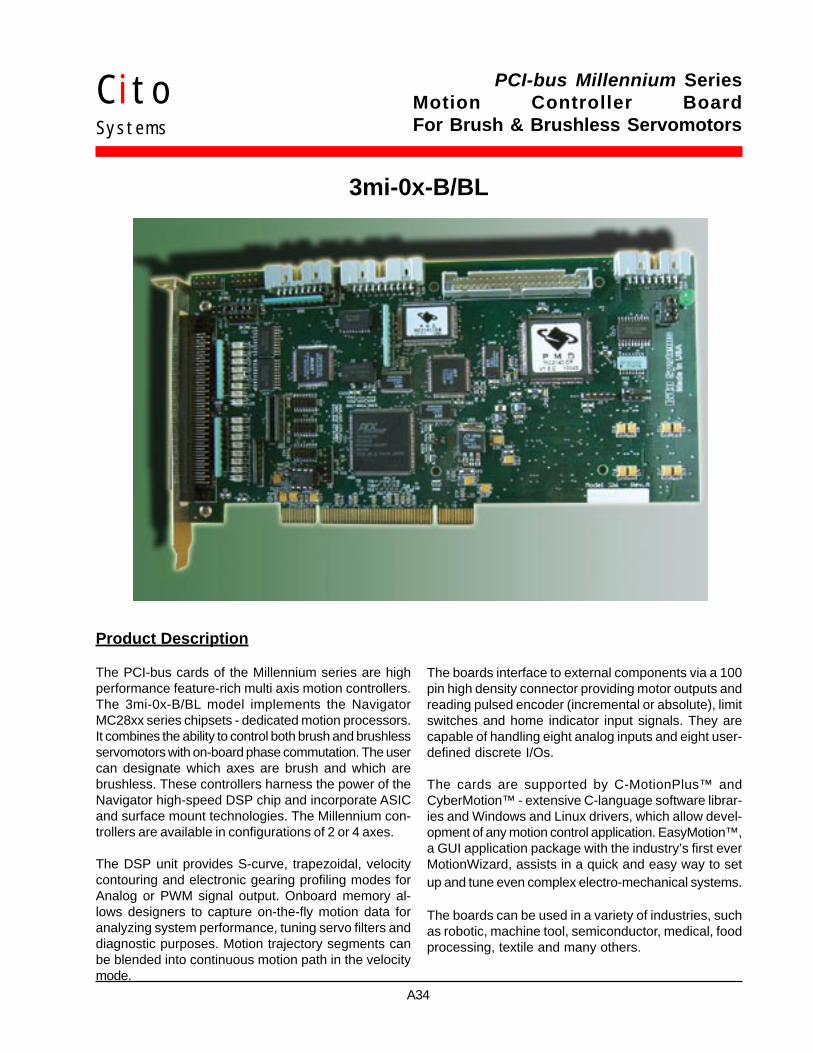
The PCI-bus cards of the Millennium series are highperformance feature-rich multi axis motion controllers.The 3mi-0x-B/BL model implements the NavigatorMC28xx series chipsets - dedicated motion processors.It combines the ability to control both brush and brushlessservomotors with on-board phase commutation. The usercan designate which axes are brush and which arebrushless. These controllers harness the power of theNavigator high-speed DSP chip and incorporate ASICand surface mount technologies. The Millennium con-trollers are available in configurations of 2 or 4 axes.
The DSP unit provides S-curve, trapezoidal, velocitycontouring and electronic gearing profiling modes forAnalog or PWM signal output. Onboard memory al-lows designers to capture on-the-fly motion data foranalyzing system performance, tuning servo filters anddiagnostic purposes. Motion trajectory segments canbe blended into continuous motion path in the velocitymode.
The boards interface to external components via a 100pin high density connector providing motor outputs andreading pulsed encoder (incremental or absolute), limitswitches and home indicator input signals. They arecapable of handling eight analog inputs and eight user-defined discrete I/Os.
The cards are supported by C-MotionPlus™ andCyberMotion™ - extensive C-language software librar-ies and Windows and Linux drivers, which allow devel-opment of any motion control application. EasyMotion™,a GUI application package with the industry’s first everMotionWizard, assists in a quick and easy way to setup and tune even complex electro-mechanical systems.
The boards can be used in a variety of industries, suchas robotic, machine tool, semiconductor, medical, foodprocessing, textile and many others.
PCI-bus Millennium SeriesMotion Controller BoardFor Brush & Brushless Servomotors
A34
3mi-0x-B/BL
C i t oS y s t e m s

Features:
Uses DSP and ASIC high speed dedicated motion processors in 2 or 4 axes configurationSupports single phase brushed and 2 or 3-phase brushless motors6-step (Hall based) or sinusoidal commutation of brushless motors onlyIndependent or synchronous axes programmingOpen or closed servo loop operating modesAdvanced PID filter with velocity and acceleration feedforward, bias offset and 32-bit position errorAxis settled indicator and tracking window in addition to automatic motion error detectionChoice of S-curve, trapezoidal, velocity contouring or electronic gearing motion profilesAsymmetric acceleration and deceleration to custom program a trapezoidal motion profileVelocity and acceleration changes on-the-fly for trapezoidal and velocity contouring profilesPosition range from –2,147,483,648 to +2,147,483,647 countsVelocity range from -32,768 to +32,767 counts/sample with a resolution of 1/65,536 counts/sample invelocity contouring profile mode or from 0 to 32,767 counts/sample with a resolution of 1/65,536counts/sample in all other modesAcceleration and deceleration range from –32,768 to 32,767 counts/sample2 with a resolution of1/65,536 counts/sample2
Jerk range from 0 to 1 counts/sample3 with a resolution of 1/4,294,967,296 counts/sample3
Electronic gear ratio range from –32,768 to 32,767 (negative and positive direction)Programmable sample rate from 150 µsec to 3355 msec per axisSingle-ended or differential incremental encoder maximum rate up to 5.0 Mcounts/secMaximum parallel feedback device rate up to 160.0 Mcounts/secParallel feedback device word size: 16 bits3 Hall effect input signals per axis (TTL level) for brushless motors onlyCommutation rate 10 kHz for 4 axes or 20 kHz for 2 axes+/-10V differential 16-bit DAC output signalPWM motor output signal of 10-bit resolution at 20 kHz – 50/50 PWM mode supports 1, 2 or 3 phasemotors, Sign/Magnitude PWM mode supports 1 or 2 phase motors onlyOn-board 64 kByte dual-port memory buffer for data and parameters storagePCI-bus communication interfaceOpto-isolated dedicated inputs for two-directional travel limit switches, home indicator and fault signaloperating at +5V, +12V, +24V or +48V8 general purpose discrete TTL level input lines8 uncommitted discrete output lines operating at TTL level, expandable to 128 outputs or opto-isolatedcapable of sinking or sourcing maximum 350 mA at 50V8 general purpose 10-bit analog inputs in range of 0 to 5.0 V dcAutomatic motor shutdown on motion errorProgrammable host interruptsTrace capabilities for system performance testing, servo-filter tuning and diagnostic purposesSoftware functions support coordinated linear and circular interpolation, point-to-point positioningand contouring, backlash compensation, jogging, homing, etc.Status reporting for position, speed and errorsInfinite number of linear and arc segments for smooth motionProgrammable event triggers for monitoring elapsed time, motion complete, position, motion error,limit switches and position wrap-around
A35

01 QuadA1+02 QuadA1-03 QuadB1+04 QuadB1-05 Index1+06 Index1-07 Vcc (encoder)08 GND (encoder)09 Hall1A*10 Hall1B*11 Hall1C*12 GND (Hall)13 PosLim114 NegLim115 Home116 AxisIn117 AxisOut118 PWMMagA119 PWMMagB1*20 PWMMagC1*21 Not used22 DACA123 DACB1*24 GND (DAC)25 Opto GND
26 QuadA2+27 QuadA2-28 QuadB2+29 QuadB2-30 Index2+31 Index2-32 Vcc (encoder)33 GND (encoder)34 Hall2A*35 Hall2B*36 Hall2C*37 GND (Hall)38 PosLim239 NegLim240 Home241 AxisIn242 AxisOut243 PWMMagA244 PWMMagB2*45 PWMMagC2*46 Not used47 DACA248 DACB2*49 GND (DAC)50 Opto GND
51 QuadA3+52 QuadA3-53 QuadB3+54 QuadB3-55 Index3+56 Index3-57 Vcc (encoder)58 GND (encoder)59 Hall3A*60 Hall3B*61 Hall3C*62 GND (Hall)63 PosLim364 NegLim365 Home366 AxisIn367 AxisOut368 PWMMagA369 PWMMagB3*70 PWMMagC3*71 Not used72 DACA373 DACB3*74 GND (DAC)75 Opto GND
76 QuadA4+77 QuadA4-78 QuadB4+79 QuadB4-80 Index4+81 Index4-82 Vcc (encoder)83 GND (encoder)84 Hall4A*85 Hall4B*86 Hall4C*87 GND (Hall)88 PosLim489 NegLim490 Home491 AxisIn492 AxisOut493 PWMMagA494 PWMMagB4*95 PWMMagC4*99 Not used97 DACA498 DACB4*99 GND (DAC)100 Opto GND
Pin Signal Name Pin Signal Name Pin Signal Name Pin Signal Name
Axes Control Signals Connector (J4)
A36
* - depends on user axes designation
01 PrlIn002 PrlOut003 PrlIn104 PrlOut105 PrlIn206 PrlOut207 PrlIn308 PrlOut309 PrlIn410 PrlOut4
User-defined Digital I/O Connector (J5)
11 PrlIn512 PrlOut513 PrlIn614 PrlOut615 PrlIn716 PrlOut717 GND18 Vcc19 GND20 Vcc
Pin Signal Name Pin Signal Name
01 Analog102 Analog203 Analog304 Analog405 Analog506 Analog607 Analog708 Analog8
Analog Input Connector (J1)
09 AnalogRefHigh10 AnalogRefLow11 AnalogVcc12 AnalogGND13 Vcc14 GND15 Synch16 ~HostIntrpt
Pin Signal Name Pin Signal Name
01 SrlXmt02 SrlRcv03 Synch04 GND05 Vcc
Pin Signal Name
Serial Channel Connector (J2)01 High PrlOut002 +VS03 High PrlOut104 +VS05 High PrlOut206 +VS07 High PrlOut308 +VS
High Power I/O Connector (J7)
09 High PrlOut410 Pwr GND11 High PrlOut512 Pwr GND13 High PrlOut614 Pwr GND15 High PrlOut716 Pwr GND
Pin Signal Name Pin Signal Name

Environmental and Electrical Ratings
Dimensions 4.00” x 8.25”Storage Temperature -40 °C to 125 °COperating Temperature 0 °C to 70 °C (an industrial version with an operating range of –40 °C
to 85 °C is also available)Power Consumption 1A @ 5V; 83mA @ +/-12VSupply Voltage Limits -0.3V to +7.0VSupply Voltage Operating Range 4.75V to 5.25VAnalog Output Range -10.0V to 10.0VAnalog Input Range 0.0V to 5.0V
Ordering information
3mi - 0 - BL/B
A - analog output signalP - PWM output signal
2 - 2 axis controller 4 - 4 axis controller
A37

Product Description
The PCI-bus cards of the Millennium series are highperformance feature-rich multi axis motion controllers.The 3mi-0x-MS model implements the NavigatorMC24xx series chipsets - dedicated motion processorsto control microstepping motors. These controllers har-ness the power of the Navigator high-speed DSP chipand incorporate ASIC and surface mount technologies.The Millennium controllers are available in configurationsof 1, 2 or 4 axes.
The DSP unit provides S-curve, trapezoidal, velocitycontouring and electronic gearing profiling modes forAnalog or PWM signal output. Onboard memory al-lows designers to capture on-the-fly motion data foranalyzing system performance and diagnostic pur-poses. Motion trajectory segments can be blended intocontinuous motion path in the velocity mode.The boards interface to external components via a 100
pin high density connector providing motor outputs andreading pulsed encoder (incremental or absolute) foron-the-fly motor stall detection, limit switches and homeindicator input signals. They are capable of handlingeight analog inputs and eight user-defined discrete I/Os.
The cards are supported by C-MotionPlus™ andCyberMotion™ - extensive C-language software librar-ies and Windows and Linux drivers, which allow devel-opment of any motion control application. EasyMotion™,a GUI application package with the industry’s first everMotionWizard, assists in a quick and easy way to setup and tune even complex electro-mechanical systems.
The boards can be used in a variety of industries, suchas robotic, machine tool, semiconductor, medical, foodprocessing, textile and many others.
PCI-bus Millennium SeriesMotion Controller BoardFor Microstepping Motors
A38
3mi-0x-MS
C i t oS y s t e m s

Features:
Uses DSP and ASIC high speed dedicated motion processors in 1, 2 or 4 axes configurationSupports 2 or 3-phase stepping motorsProgrammable microstepping rate from 1 to 256 counts per full stepIndependent or synchronous axes programmingOpen loop operating modeChoice of S-curve, trapezoidal, velocity contouring or electronic gearing motion profilesAsymmetric acceleration and deceleration to custom program a trapezoidal motion profileVelocity and acceleration changes on-the-fly for trapezoidal and velocity contouring profilesPosition range from –2,147,483,648 to +2,147,483,647 countsVelocity range from -32,768 to +32,767 counts/sample with a resolution of 1/65,536 counts/sample invelocity contouring profile mode or from 0 to 32,767 counts/sample with a resolution of 1/65,536counts/sample in all other modesAcceleration and deceleration range from –32,768 to 32,767 counts/sample2 with a resolution of1/65,536 counts/sample2
Jerk range from 0 to 1/2 counts/sample3 with a resolution of 1/4,294,967,296 counts/sample3
Electronic gear ratio range from –32,768 to 32,767 (negative and positive direction)Programmable sample rate from 150 µsec to 3355 msec per axisSingle-ended or differential incremental encoder maximum rate up to 5.0 Mcounts/secMaximum parallel encoder rate up to 160.0 Mcounts/secParallel encoder word size: 16 bitsParallel encoder read rate: 20kHz (every 50 µsec)Commutation rate 10 kHz for 4 axes or 20 kHz for 1 and 2 axes+/-10V 16-bit DAC output signalPWM motor output signal of 8-bit resolution at 80 kHz or 10-bit resolution at 20 kHzOn-board 64 kByte dual-port memory buffer for data and parameters storagePCI-bus communication interfaceOpto-isolated dedicated inputs for two-directional travel limit switches, home indicator and fault signaloperating at +5V, +12V, +24V or +48V8 general purpose discrete TTL level input lines8 uncommitted discrete output lines operating at TTL level, expandable to 128 outputs or opto-isolatedcapable of sinking or sourcing maximum 350 mA at 50V8 general purpose 10-bit analog inputs in range of 0 to 5.0 V dcAutomatic motor shutdown on motion errorProgrammable host interruptsTrace capabilities for system performance testing and diagnostic purposesSoftware functions support coordinated linear and circular interpolation, point-to-point positioningand contouring, backlash compensation, jogging, homing, etc.Status reporting for position, speed and errorsInfinite number of linear and arc segments for smooth motionProgrammable event triggers for monitoring elapsed time, motion complete, position, motion error,limit switches and position wrap-around
A39

01 QuadA1+02 QuadA1-03 QuadB1+04 QuadB1-05 Index1+06 Index1-07 Vcc (encoder)08 GND (encoder)09 N.C.10 N.C.11 N.C.12 GND13 PosLim114 NegLim115 Home116 AxisIn117 AxisOut118 PWMMagA119 PWMMagB120 PWMSignA121 PWMSignB122 DACA123 DACB124 GND (DAC)25 Opto GND
26 QuadA2+27 QuadA2-28 QuadB2+29 QuadB2-30 Index2+31 Index2-32 Vcc (encoder)33 GND (encoder)34 N.C.35 N.C.36 N.C.37 GND38 PosLim239 NegLim240 Home241 AxisIn242 AxisOut243 PWMMagA244 PWMMagB245 PWMSignA246 PWMSignB247 DACA248 DACB249 GND (DAC)50 Opto GND
51 QuadA3+52 QuadA3-53 QuadB3+54 QuadB3-55 Index3+56 Index3-57 Vcc (encoder)58 GND (encoder)59 N.C.60 N.C.61 N.C.62 GND63 PosLim364 NegLim365 Home366 AxisIn367 AxisOut368 PWMMagA369 PWMMagB370 PWMSignA371 PWMSignB372 DACA373 DACB374 GND (DAC)75 Opto GND
76 QuadA4+77 QuadA4-78 QuadB4+79 QuadB4-80 Index4+81 Index4-82 Vcc (encoder)83 GND (encoder)84 N.C.85 N.C.86 N.C.87 GND88 PosLim489 NegLim490 Home491 AxisIn492 AxisOut493 PWMMagA494 PWMMagB495 PWMSignA499 PWMSignB497 DACA498 DACB499 GND (DAC)100 Opto GND
Pin Signal Name Pin Signal Name Pin Signal Name Pin Signal Name
Axes Control Signals Connector (J4)
A40
01 PrlIn002 PrlOut003 PrlIn104 PrlOut105 PrlIn206 PrlOut207 PrlIn308 PrlOut309 PrlIn410 PrlOut4
User-defined Digital I/O Connector (J5)
11 PrlIn512 PrlOut513 PrlIn614 PrlOut615 PrlIn716 PrlOut717 GND18 Vcc19 GND20 Vcc
Pin Signal Name Pin Signal Name
01 Analog102 Analog203 Analog304 Analog405 Analog506 Analog607 Analog708 Analog8
Analog Input Connector (J1)
09 AnalogRefHigh10 AnalogRefLow11 AnalogVcc12 AnalogGND13 Vcc14 GND15 Synch16 ~HostIntrpt
Pin Signal Name Pin Signal Name
01 SrlXmt02 SrlRcv03 Synch04 GND05 Vcc
Pin Signal Name
Serial Channel Connector (J2)01 High PrlOut002 +VS03 High PrlOut104 +VS05 High PrlOut206 +VS07 High PrlOut308 +VS
High Power I/O Connector (J7)
09 High PrlOut410 Pwr GND11 High PrlOut512 Pwr GND13 High PrlOut614 Pwr GND15 High PrlOut716 Pwr GND
Pin Signal Name Pin Signal Name

Environmental and Electrical Ratings
Dimensions 4.00” x 8.25”Storage Temperature -40 °C to 125 °COperating Temperature 0 °C to 70 °C (an industrial version with an operating range of –40 °C
to 85 °C is also available)Power Consumption 1A @ 5V; 83mA @ +/-12VSupply Voltage Limits -0.3V to +7.0VSupply Voltage Operating Range 4.75V to 5.25VAnalog Output Range -10.0V to 10.0VAnalog Input Range 0.0V to 5.0V
Ordering information
3mi - 0 - MS
A - analog output signalP - PWM output signal
1 - 1 axis controller 2 - 2 axis controller 4 - 4 axis controller
A41

Product Description
The PCI-bus cards of the Millennium series are highperformance feature-rich multi axis motion controllers.The 3mi-0x-S model implements the Navigator MC25xxseries chipsets - dedicated motion processors to con-trol stepper motors. These controllers harness the powerof the Navigator high-speed DSP chip and incorporateASIC and surface mount technologies. The Millenniumcontrollers are available in configurations of 1, 2 or 4axes.
The DSP unit provides S-curve, trapezoidal, velocitycontouring and electronic gearing profiling modes forpulse and direction signal output. Onboard memory al-lows designers to capture on-the-fly motion data foranalyzing system performance and diagnostic pur-poses. Motion trajectory segments can be blended intocontinuous motion path in the velocity mode.
The boards interface to external components via a 100
pin high density connector providing motor outputs andreading pulsed encoder (incremental or absolute) for on-the-fly motor stall detection, limit switches and homeindicator input signals. They are capable of handlingeight analog inputs and eight user-defined discreteinputs and outputs.
The cards are supported by C-MotionPlus™ andCyberMotion™ - extensive C-language software librar-ies and Windows and Linux drivers, which allow devel-opment of any motion control application. EasyMotion™,a GUI application package with the industry’s first everMotionWizard, assists in a quick and easy way to setup and tune even complex electro-mechanical systems.
The boards can be used in a variety of industries, suchas robotic, machine tool, semiconductor, medical, foodprocessing, textile and many others.
PCI-bus Millennium SeriesMotion Controller Board
For Stepper Motors
A42
3mi-0x-S
C i t oS y s t e m s

Features:
Uses DSP and ASIC high speed dedicated motion processors in 1, 2 or 4 axes configurationIndependent or synchronous axes programmingOpen loop or stall detection with encoder feedback operating modesChoice of S-curve, trapezoidal, velocity contouring or electronic gearing motion profilesAsymmetric acceleration and deceleration to custom program a trapezoidal motion profileVelocity and acceleration changes on-the-fly for trapezoidal and velocity contouring profilesPosition range from –2,147,483,648 to +2,147,483,647 countsVelocity range from -32,768 to +32,767 counts/sample with a resolution of 1/65,536 counts/sampleAcceleration and deceleration range from –32,768 to 32,767 counts/sample2 with a resolution of1/65,536 counts/sample2
Jerk range from 0 to 1/2 counts/sample3 with a resolution of 1/4,294,967,296 counts/sample3
Electronic gear ratio range from –32,768 to 32,767 (negative and positive direction)Programmable sample rate from 100 µsec to 3355 msec per axisSingle-ended or differential incremental encoder maximum rate up to 5.0 Mcounts/secMaximum parallel encoder rate up to 160.0 Mcounts/secParallel encoder word size: 16 bitsParallel encoder read rate: 20kHz (every 50 µsec)Pulse and direction motor output up to 4.98 M-pulses/secOn-board 64 kByte dual-port memory buffer for data and parameters storagePCI-bus communication interfaceOpto-isolated dedicated inputs for two-directional travel limit switches, home indicator and fault signaloperating at +5V, +12V, +24V or +48V8 general purpose discrete TTL level input lines8 uncommitted discrete output lines operating at TTL level, expandable to 128 outputs or opto-isolatedcapable of sinking or sourcing maximum 350 mA at 50V8 general purpose 10-bit analog inputs in range of 0 to 5.0 V dcAutomatic motor shutdown on motion errorProgrammable host interruptsTrace capabilities for system performance testing and diagnostic purposesSoftware functions support coordinated linear and circular interpolation, point-to-point positioningand contouring, backlash compensation, jogging, homing, etc.Status reporting for position, speed and errorsInfinite number of linear and arc segments for smooth motionProgrammable event triggers for monitoring elapsed time, motion complete, position, motion error,limit switches and position wrap-around
A43

01 QuadA1+02 QuadA1-03 QuadB1+04 QuadB1-05 Index1+06 Index1-07 Vcc (encoder)08 GND (encoder)09 N.C.10 N.C.11 N.C.12 GND13 PosLim114 NegLim115 Home116 AxisIn117 AxisOut118 Pulse119 N.C.20 N.C.21 Direction122 N.C.23 N.C.24 GND25 Opto GND
26 QuadA2+27 QuadA2-28 QuadB2+29 QuadB2-30 Index2+31 Index2-32 Vcc (encoder)33 GND (encoder)34 N.C.35 N.C.36 N.C.37 GND38 PosLim239 NegLim240 Home241 AxisIn242 AxisOut243 Pulse244 N.C.45 N.C.46 Direction247 N.C.48 N.C.49 GND50 Opto GND
51 QuadA3+52 QuadA3-53 QuadB3+54 QuadB3-55 Index3+56 Index3-57 Vcc (encoder)58 GND (encoder)59 N.C.60 N.C.61 N.C.62 GND63 PosLim364 NegLim365 Home366 AxisIn367 AxisOut368 Pulse369 N.C.70 N.C.71 Direction372 N.C.73 N.C.74 GND75 Opto GND
76 QuadA4+77 QuadA4-78 QuadB4+79 QuadB4-80 Index4+81 Index4-82 Vcc (encoder)83 GND (encoder)84 N.C.85 N.C.86 N.C.87 GND88 PosLim489 NegLim490 Home491 AxisIn492 AxisOut493 Pulse494 N.C.95 N.C.99 Direction497 N.C.98 N.C.99 GND100 Opto GND
Pin Signal Name Pin Signal Name Pin Signal Name Pin Signal Name
Axes Control Signals Connector (J4)
A44
01 PrlIn002 PrlOut003 PrlIn104 PrlOut105 PrlIn206 PrlOut207 PrlIn308 PrlOut309 PrlIn410 PrlOut4
User-defined Digital I/O Connector (J5)
11 PrlIn512 PrlOut513 PrlIn614 PrlOut615 PrlIn716 PrlOut717 GND18 Vcc19 GND20 Vcc
Pin Signal Name Pin Signal Name
01 Analog102 Analog203 Analog304 Analog405 Analog506 Analog607 Analog708 Analog8
Analog Input Connector (J1)
09 AnalogRefHigh10 AnalogRefLow11 AnalogVcc12 AnalogGND13 Vcc14 GND15 Synch16 ~HostIntrpt
Pin Signal Name Pin Signal Name
01 SrlXmt02 SrlRcv03 Synch04 GND05 Vcc
Pin Signal Name
Serial Channel Connector (J2)01 High PrlOut002 +VS03 High PrlOut104 +VS05 High PrlOut206 +VS07 High PrlOut308 +VS
High Power I/O Connector (J7)
09 High PrlOut410 Pwr GND11 High PrlOut512 Pwr GND13 High PrlOut614 Pwr GND15 High PrlOut716 Pwr GND
Pin Signal Name Pin Signal Name

Environmental and Electrical Ratings
Dimensions 4.00” x 8.25”Storage Temperature -40 °C to 125 °COperating Temperature 0 °C to 70 °C (an industrial version with an operating range of –40 °C
to 85 °C is also available)Power Consumption 1A @ 5VSupply Voltage Limits -0.3V to +7.0VSupply Voltage Operating Range 4.75V to 5.25VAnalog Intput Range 0.0V to 5.0V
Ordering information
3mi - 0 - S
1 - 1 axis controller 2 - 2 axis controller 4 - 4 axis controller
A45

Product Description
The PC/104-bus cards of the Millennium series are highperformance feature-rich multi axis motion controllers,ideal for embedded system applications. The 3mc-0x-Bmodel implements the Navigator MC21xx series chipsets- dedicated motion processors to control brush orbrushless servomotors. These controllers harness thepower of the Navigator high-speed DSP chip and incor-porate ASIC and surface mount technologies. The Mil-lennium controllers are available in configurations of 1, 2or 4 axes.
The DSP unit provides S-curve, trapezoidal, velocitycontouring and electronic gearing profiling modes forAnalog or PWM signal output. Onboard memory al-lows designers to capture on-the-fly motion data foranalyzing system performance, tuning servo filters anddiagnostic purposes. Motion trajectory segments canbe blended into continuous motion path in the velocitymode.
The boards interface to external components via a 100pin high density connector providing motor outputs andreading pulsed encoder (incremental or absolute), limitswitches and home indicator input signals. They arecapable of handling eight analog inputs and eight user-defined discrete I/Os.
The cards are supported by C-MotionPlus™ andCyberMotion™ - extensive C-language software librar-ies and Windows and Linux drivers, which allow devel-opment of any motion control application. EasyMotion™,a GUI application package with the industry’s first everMotionWizard, assists in a quick and easy way to setup and tune even complex electro-mechanical systems.
The boards can be used in a variety of industries, suchas robotic, machine tool, semiconductor, medical, foodprocessing, textile and many others.
PC/104-bus Millennium Series Motion Controller BoardFor Brush Servomotors
3mc-0x-B
A46
C i t oS y s t e m s

Features:
Uses DSP and ASIC high speed dedicated motion processors in 1, 2 or 4 axes configurationIndependent or synchronous axes programmingOpen or closed servo loop operating modesAdvanced PID filter with velocity and acceleration feedforward, bias offset and 32-bit position errorAxis settled indicator and tracking window in addition to automatic motion error detectionChoice of S-curve, trapezoidal, velocity contouring or electronic gearing motion profilesAsymmetric acceleration and deceleration to custom program a trapezoidal motion profileVelocity and acceleration changes on-the-fly for trapezoidal and velocity contouring profilesPosition range from –2,147,483,648 to +2,147,483,647 countsVelocity range from -32,768 to +32,767 counts/sample with a resolution of 1/65,536 counts/sample invelocity contouring profile mode or from 0 to 32,767 counts/sample with a resolution of 1/65,536counts/sample in all other modesAcceleration and deceleration range from –32,768 to 32,767 counts/sample2 with a resolution of1/65,536 counts/sample2
Jerk range from 0 to 1 counts/sample3 with a resolution of 1/4,294,967,296 counts/sample3
Electronic gear ratio range from –32,768 to 32,767 (negative and positive direction)Programmable sample rate from 100 µsec to 3355 msec per axisSingle-ended or differential incremental encoder maximum rate up to 5.0 Mcounts/secMaximum parallel feedback device rate up to 160.0 Mcounts/secParallel feedback device word size: 16 bits+/-10V differential 16-bit DAC output signalPWM motor output signal of 10-bit resolution at 20 kHzOn-board 64 kByte dual-port memory buffer for data and parameters storagePC/104-bus communication interfaceProgrammable watchdog timerProgrammable software resetPower supply voltage monitor circuit to reset the boardExternal reset circuitOpto-isolated dedicated outputs for amplifier enable signalsOpto-isolated dedicated inputs for two-directional travel limit switches, home indicator and fault signaloperating at +5V, +12V, +24V or +48V8 general purpose discrete TTL level input lines8 uncommitted discrete output lines operating at TTL level, expandable to 128 outputs or opto-isolatedcapable of sinking or sourcing maximum 350 mA at 50V8 general purpose 10-bit analog inputs in range of 0 to 5.0 V dcAutomatic motor shutdown on motion errorProgrammable host interruptsTrace capabilities for system performance testing, servo-filter tuning and diagnostic purposesSoftware functions support coordinated linear and circular interpolation, point-to-point positioning andcontouring, backlash compensation, jogging, homing, etc.Status reporting for position, speed and errorsInfinite number of linear and arc segments for smooth motionProgrammable event triggers for monitoring elapsed time, motion complete, position, motion error, limitswitches and position wrap-around
A47

01 QuadA1+02 QuadA1-03 QuadB1+04 QuadB1-05 Index1+06 Index1-07 Vcc (encoder)08 GND (encoder)09 Not used10 Not used11 Not used12 GND13 PosLim114 NegLim115 Home116 AxisIn117 AxisOut118 PWMMag119 Not used20 Not used21 PWMsign122 DAC123 /DAC124 GND (DAC)25 OPTO GND
26 QuadA2+27 QuadA2-28 QuadB2+29 QuadB2-30 Index2+31 Index2-32 Vcc (encoder)33 GND (encoder)34 Not used35 Not used36 Not used37 GND38 PosLim239 NegLim240 Home241 AxisIn242 AxisOut243 PWMMag244 Not used45 Not used46 PWMsign247 DAC248 /DAC249 GND (DAC)50 OPTO GND
51 QuadA3+52 QuadA3-53 QuadB3+54 QuadB3-55 Index3+56 Index3-57 Vcc (encoder)58 GND (encoder)59 Not used60 Not used61 Not used62 GND63 PosLim364 NegLim365 Home366 AxisIn367 AxisOut368 PWMMag369 Not used70 Not used71 PWMsign372 DAC373 /DAC374 GND (DAC)75 OPTO GND
76 QuadA4+77 QuadA4-78 QuadB4+79 QuadB4-80 Index4+81 Index4-82 Vcc (encoder)83 GND (encoder)84 Not used85 Not used86 Not used87 GND88 PosLim489 NegLim490 Home491 AxisIn492 AxisOut493 PWMMag494 Not used95 Not used99 PWMsign497 DAC498 /DAC499 GND (DAC)100 OPTO GND
Pin Signal Name Pin Signal Name Pin Signal Name Pin Signal Name
Axes Control Signals Connector (J7)
01 PrlIn002 PrlIn103 PrlIn204 PrlIn305 PrlIn406 PrlIn5PrlOut207 PrlIn608 PrlIn7PrlOut309 PrlOut010 PrlOut111 PrlOut2
Miscellaneous I/O Connector (J12)
12 PrlOut313 PrlOut414 PrlOut515 PrlOut616 PrlOut717 High PrlOut018 High PrlOut119 High PrlOut220 High PrlOut321 High PrlOut422 High PrlOut5
Pin Signal Name Pin Signal Name
23 High PrlOut624 High PrlOut725 AnalogIn026 AnalogIn127 AnalogIn228 AnalogIn329 AnalogIn430 AnalogIn531 AnalogIn632 AnalogIn733 AnalogRefHigh
34 AnalogRefLow35 AnalogVcc36 AnalogGND37 Amp Enable038 Amp Enable139 Amp Enable240 Amp Enable341 Amp +VS42 Amp GND43 Reset Out44 Hstrdy
Pin Signal Name Pin Signal Name
01 SrlXmt02 SrlRcv03 Synch04 RDSSN05 Vcc06 GND
Pin Signal Name
Serial Channel (J2)
A48
Pin Signal Name
SYNCH Sig. (J1)Pin Signal Name
HSTINT Sig. (J3)
01 SYNCH02 GND
01 HSTINT~02 GND
Pin Signal Name
Power Connector (J9)
01 +VS02 Pwr GND03 VCC04 GND

Environmental and Electrical Ratings
Dimensions 3.5” x 3.8” (90mm x 96mm), max 4.2” x 3.8” (107mm x 96mm)Storage Temperature -40 °C to 125 °COperating Temperature 0 °C to 70 °C (an industrial version with an operating range of –40 °C
to 85 °C is also available)Power Consumption 0.5A @ 5V; 40mA @ +/-12VSupply Voltage Limits -0.3V to +7.0VSupply Voltage Operating Range 4.75V to 5.25VAnalog Output Range -10.0V to 10.0VAnalog Input Range 0.0V to 5.0V
Ordering information
3mc - 0 - B
A - analog output signalP - PWM output signal
1 - 1 axis controller2 - 2 axis controller4 - 4 axis controller
A49

Product Description
The PC/104-bus cards of the Millennium series are highperformance feature-rich multi axis motion controllers,ideal for embedded system applications. The 3mc-0x-BL model implements the Navigator MC23xx serieschipsets - dedicated motion processors. It controlsbrushless servomotors with on-board phase commuta-tion. These controllers harness the power of the Naviga-tor high-speed DSP chip and incorporate ASIC and sur-face mount technologies. The Millennium controllers areavailable in configurations of 1, 2 or 4 axes.
The DSP unit provides S-curve, trapezoidal, velocitycontouring and electronic gearing profiling modes forAnalog or PWM signal output. Onboard memory al-lows designers to capture on-the-fly motion data foranalyzing system performance, tuning servo filters anddiagnostic purposes. Motion trajectory segments canbe blended into continuous motion path in the velocitymode.
The boards interface to external components via a 100pin high density connector providing motor outputs andreading pulsed encoder (incremental or absolute), limitswitches and home indicator input signals. They arecapable of handling eight analog inputs and eight user-defined discrete I/Os.
The cards are supported by C-MotionPlus™ andCyberMotion™ - extensive C-language software librar-ies and Windows and Linux drivers, which allow devel-opment of any motion control application. EasyMotion™,a GUI application package with the industry’s first everMotionWizard, assists in a quick and easy way to setup and tune even complex electro-mechanical systems.
The boards can be used in a variety of industries, suchas robotic, machine tool, semiconductor, medical, foodprocessing, textile and many others.
PC/104-bus Millennium SeriesMotion Controller BoardFor Brushless Servomotors
A50
3mc-0x-BL
C i t oS y s t e m s

Features:
Uses DSP and ASIC high speed dedicated motion processors in 1, 2 or 4 axes configurationSupports 2 or 3-phase brushless motors6-step (Hall based) or sinusoidal commutationIndependent or synchronous axes programmingOpen or closed servo loop operating modesAdvanced PID filter with velocity and acceleration feedforward, bias offset and 32-bit position errorAxis settled indicator and tracking window in addition to automatic motion error detectionChoice of S-curve, trapezoidal, velocity contouring or electronic gearing motion profilesAsymmetric acceleration and deceleration to custom program a trapezoidal motion profileVelocity and acceleration changes on-the-fly for trapezoidal and velocity contouring profilesPosition range from –2,147,483,648 to +2,147,483,647 countsVelocity range from -32,768 to +32,767 counts/sample with a resolution of 1/65,536 counts/sample invelocity contouring profile mode or from 0 to 32,767 counts/sample with a resolution of 1/65,536counts/sample in all other modesAcceleration and deceleration range from –32,768 to 32,767 counts/sample2 with a resolution of1/65,536 counts/sample2
Jerk range from 0 to 1 counts/sample3 with a resolution of 1/4,294,967,296 counts/sample3
Electronic gear ratio range from –32,768 to 32,767 (negative and positive direction)Programmable sample rate from 150 µsec to 3355 msec per axisSingle-ended or differential incremental encoder maximum rate up to 5.0 Mcounts/secMaximum parallel feedback device rate up to 160.0 Mcounts/secParallel feedback device word size: 16 bits3 Hall effect input signals per axis (TTL level)Commutation rate 10 kHz for 4 axes or 20 kHz for 1 and 2 axes+/-10V 16-bit DAC output signalPWM motor output signal of 10-bit resolution at 20 kHz (1 or 2 axes) or 10-bit resolution at 10 kHz(4 axes) – 50/50 PWM mode supports 2 or 3 phase motors, Sign/Magnitude PWM mode supports2 phase motors onlyOn-board 64 kByte dual-port memory buffer for data and parameters storagePC/104-bus communication interfaceProgrammable watchdog timerProgrammable software resetPower supply voltage monitor circuit to reset the boardExternal reset circuitOpto-isolated dedicated outputs for amplifier enable signalsOpto-isolated dedicated inputs for two-directional travel limit switches, home indicator and fault signaloperating at +5V, +12V, +24V or +48V8 general purpose discrete TTL level input lines8 uncommitted discrete output lines operating at TTL level, expandable to 128 outputs or opto-isolatedcapable of sinking or sourcing maximum 350 mA at 50V8 general purpose 10-bit analog inputs in range of 0 to 5.0 V dcAutomatic motor shutdown on motion errorProgrammable host interruptsTrace capabilities for system performance testing, servo-filter tuning and diagnostic purposesSoftware functions support coordinated linear and circular interpolation, point-to-point positioningand contouring, backlash compensation, jogging, homing, etc.Status reporting for position, speed and errorsInfinite number of linear and arc segments for smooth motionProgrammable event triggers for monitoring elapsed time, motion complete, position, motion error,limit switches and position wrap-around
A51
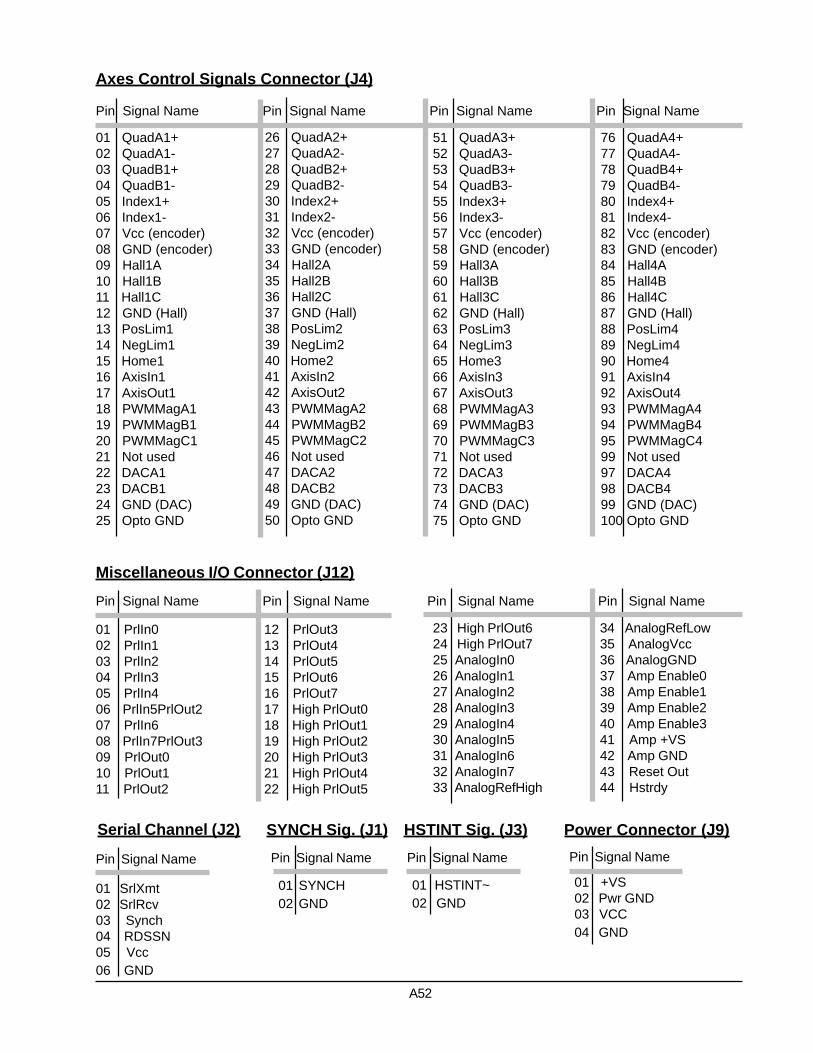
01 QuadA1+02 QuadA1-03 QuadB1+04 QuadB1-05 Index1+06 Index1-07 Vcc (encoder)08 GND (encoder)09 Hall1A10 Hall1B11 Hall1C12 GND (Hall)13 PosLim114 NegLim115 Home116 AxisIn117 AxisOut118 PWMMagA119 PWMMagB120 PWMMagC121 Not used22 DACA123 DACB124 GND (DAC)25 Opto GND
26 QuadA2+27 QuadA2-28 QuadB2+29 QuadB2-30 Index2+31 Index2-32 Vcc (encoder)33 GND (encoder)34 Hall2A35 Hall2B36 Hall2C37 GND (Hall)38 PosLim239 NegLim240 Home241 AxisIn242 AxisOut243 PWMMagA244 PWMMagB245 PWMMagC246 Not used47 DACA248 DACB249 GND (DAC)50 Opto GND
51 QuadA3+52 QuadA3-53 QuadB3+54 QuadB3-55 Index3+56 Index3-57 Vcc (encoder)58 GND (encoder)59 Hall3A60 Hall3B61 Hall3C62 GND (Hall)63 PosLim364 NegLim365 Home366 AxisIn367 AxisOut368 PWMMagA369 PWMMagB370 PWMMagC371 Not used72 DACA373 DACB374 GND (DAC)75 Opto GND
76 QuadA4+77 QuadA4-78 QuadB4+79 QuadB4-80 Index4+81 Index4-82 Vcc (encoder)83 GND (encoder)84 Hall4A85 Hall4B86 Hall4C87 GND (Hall)88 PosLim489 NegLim490 Home491 AxisIn492 AxisOut493 PWMMagA494 PWMMagB495 PWMMagC499 Not used97 DACA498 DACB499 GND (DAC)100 Opto GND
Pin Signal Name Pin Signal Name Pin Signal Name Pin Signal Name
Axes Control Signals Connector (J4)
A52
01 PrlIn002 PrlIn103 PrlIn204 PrlIn305 PrlIn406 PrlIn5PrlOut207 PrlIn608 PrlIn7PrlOut309 PrlOut010 PrlOut111 PrlOut2
Miscellaneous I/O Connector (J12)
12 PrlOut313 PrlOut414 PrlOut515 PrlOut616 PrlOut717 High PrlOut018 High PrlOut119 High PrlOut220 High PrlOut321 High PrlOut422 High PrlOut5
Pin Signal Name Pin Signal Name
23 High PrlOut624 High PrlOut725 AnalogIn026 AnalogIn127 AnalogIn228 AnalogIn329 AnalogIn430 AnalogIn531 AnalogIn632 AnalogIn733 AnalogRefHigh
34 AnalogRefLow35 AnalogVcc36 AnalogGND37 Amp Enable038 Amp Enable139 Amp Enable240 Amp Enable341 Amp +VS42 Amp GND43 Reset Out44 Hstrdy
Pin Signal Name Pin Signal Name
01 SrlXmt02 SrlRcv03 Synch04 RDSSN05 Vcc06 GND
Pin Signal Name
Serial Channel (J2)Pin Signal Name
SYNCH Sig. (J1)Pin Signal Name
HSTINT Sig. (J3)
01 SYNCH02 GND
01 HSTINT~02 GND
Pin Signal Name
Power Connector (J9)
01 +VS02 Pwr GND03 VCC04 GND

Environmental and Electrical Ratings
Dimensions 3.5” x 3.8” (90mm x 96mm), max 4.2” x 3.8” (107mm x 96mm)Storage Temperature -40 °C to 125 °COperating Temperature 0 °C to 70 °C (an industrial version with an operating range of –40 °C
to 85 °C is also available)Power Consumption 0.5A @ 5V; 40mA @ +/-12VSupply Voltage Limits -0.3V to +7.0VSupply Voltage Operating Range 4.75V to 5.25VAnalog Output Range -10.0V to 10.0VAnalog Input Range 0.0V to 5.0V
Ordering information
3mc - 0 - BL
A - analog output signalP - PWM output signal
1 - 1 axis controller 2 - 2 axis controller 4 - 4 axis controller
A53

Product Description
The PC/104-bus cards of the Millennium series are highperformance feature-rich multi axis motion controllers,ideal for embedded system applications. The 3mc-0x-B/BL model implements the Navigator MC28xx serieschipsets - dedicated motion processors. It combines theability to control both brushed and brushless servo mo-tors with on-board phase commutation. The user candesignate which axes are brushed and which arebrushless. These controllers harness the power of theNavigator high-speed DSP chip and incorporate ASICand surface mount technologies. The Millennium con-trollers are available in configurations of 2 or 4 axes.
The DSP unit provides S-curve, trapezoidal, velocitycontouring and electronic gearing profiling modes forAnalog or PWM signal output. Onboard memory al-lows designers to capture on-the-fly motion data foranalyzing system performance, tuning servo filters anddiagnostic purposes. Motion trajectory segments canbe blended into continuous motion path in the velocity
mode.The boards interface to external components via a 100pin high density connector providing motor outputs andreading pulsed encoder (incremental or absolute), limitswitches and home indicator input signals. They arecapable of handling eight analog inputs and eight user-defined discrete I/Os.
The cards are supported by C-MotionPlus™ andCyberMotion™ - extensive C-language software librar-ies and Windows and Linux drivers, which allow devel-opment of any motion control application. EasyMotion™,a GUI application package with the industry’s first everMotionWizard, assists in a quick and easy way to setup and tune even complex electro-mechanical systems.
The boards can be used in a variety of industries, suchas robotic, machine tool, semiconductor, medical, foodprocessing, textile and many others.
PC/104-bus Millennium SeriesMotion Controller BoardFor Brush & Brushless Servomotors
A54
3mc-0x-B/BL
C i t oS y s t e m s

Features:
Uses DSP and ASIC high speed dedicated motion processors in 2 or 4 axes configurationSupports single phase brushed and 2 or 3-phase brushless motors6-step (Hall based) or sinusoidal commutation of brushless motors onlyIndependent or synchronous axes programmingOpen or closed servo loop operating modesAdvanced PID filter with velocity and acceleration feedforward, bias offset and 32-bit position errorAxis settled indicator and tracking window in addition to automatic motion error detectionChoice of S-curve, trapezoidal, velocity contouring or electronic gearing motion profilesAsymmetric acceleration and deceleration to custom program a trapezoidal motion profileVelocity and acceleration changes on-the-fly for trapezoidal and velocity contouring profilesPosition range from –2,147,483,648 to +2,147,483,647 countsVelocity range from -32,768 to +32,767 counts/sample with a resolution of 1/65,536 counts/sample invelocity contouring profile mode or from 0 to 32,767 counts/sample with a resolution of 1/65,536counts/sample in all other modesAcceleration and deceleration range from –32,768 to 32,767 counts/sample2 with a resolution of1/65,536 counts/sample2
Jerk range from 0 to 1 counts/sample3 with a resolution of 1/4,294,967,296 counts/sample3
Electronic gear ratio range from –32,768 to 32,767 (negative and positive direction)Programmable sample rate from 150 µsec to 3355 msec per axisSingle-ended or differential incremental encoder maximum rate up to 5.0 Mcounts/secMaximum parallel feedback device rate up to 160.0 Mcounts/secParallel feedback device word size: 16 bits3 Hall effect input signals per axis (TTL level) for brushless motors onlyCommutation rate 10 kHz for 4 axes or 20 kHz for 2 axes+/-10V differential 16-bit DAC output signalPWM motor output signal of 10-bit resolution at 20 kHz – 50/50 PWM mode supports 1, 2 or 3 phasemotors, Sign/Magnitude PWM mode supports 1 or 2 phase motors onlyOn-board 64 kByte dual-port memory buffer for data and parameters storagePC/104-bus communication interfaceProgrammable watchdog timerProgrammable software resetPower supply voltage monitor circuit to reset the boardExternal reset circuitOpto-isolated dedicated outputs for amplifier enable signalsOpto-isolated dedicated inputs for two-directional travel limit switches, home indicator and fault signaloperating at +5V, +12V, +24V or +48V8 general purpose discrete TTL level input lines8 uncommitted discrete output lines operating at TTL level, expandable to 128 outputs or opto-isolatedcapable of sinking or sourcing maximum 350 mA at 50V8 general purpose 10-bit analog inputs in range of 0 to 5.0 V dcAutomatic motor shutdown on motion errorProgrammable host interruptsTrace capabilities for system performance testing, servo-filter tuning and diagnostic purposesSoftware functions support coordinated linear and circular interpolation, point-to-point positioningand contouring, backlash compensation, jogging, homing, etc.Status reporting for position, speed and errorsInfinite number of linear and arc segments for smooth motionProgrammable event triggers for monitoring elapsed time, motion complete, position, motion error,limit switches and position wrap-around
A55

01 QuadA1+02 QuadA1-03 QuadB1+04 QuadB1-05 Index1+06 Index1-07 Vcc (encoder)08 GND (encoder)09 Hall1A*10 Hall1B*11 Hall1C*12 GND (Hall)13 PosLim114 NegLim115 Home116 AxisIn117 AxisOut118 PWMMagA119 PWMMagB1*20 PWMMagC1*21 Not used22 DACA123 DACB1*24 GND (DAC)25 Opto GND
26 QuadA2+27 QuadA2-28 QuadB2+29 QuadB2-30 Index2+31 Index2-32 Vcc (encoder)33 GND (encoder)34 Hall2A*35 Hall2B*36 Hall2C*37 GND (Hall)38 PosLim239 NegLim240 Home241 AxisIn242 AxisOut243 PWMMagA244 PWMMagB2*45 PWMMagC2*46 Not used47 DACA248 DACB2*49 GND (DAC)50 Opto GND
51 QuadA3+52 QuadA3-53 QuadB3+54 QuadB3-55 Index3+56 Index3-57 Vcc (encoder)58 GND (encoder)59 Hall3A*60 Hall3B*61 Hall3C*62 GND (Hall)63 PosLim364 NegLim365 Home366 AxisIn367 AxisOut368 PWMMagA369 PWMMagB3*70 PWMMagC3*71 Not used72 DACA373 DACB3*74 GND (DAC)75 Opto GND
76 QuadA4+77 QuadA4-78 QuadB4+79 QuadB4-80 Index4+81 Index4-82 Vcc (encoder)83 GND (encoder)84 Hall4A*85 Hall4B*86 Hall4C*87 GND (Hall)88 PosLim489 NegLim490 Home491 AxisIn492 AxisOut493 PWMMagA494 PWMMagB4*95 PWMMagC4*99 Not used97 DACA498 DACB4*99 GND (DAC)100 Opto GND
Pin Signal Name Pin Signal Name Pin Signal Name Pin Signal Name
Axes Control Signals Connector (J7)
* - depends on user axes designation
01 PrlIn002 PrlIn103 PrlIn204 PrlIn305 PrlIn406 PrlIn5PrlOut207 PrlIn608 PrlIn7PrlOut309 PrlOut010 PrlOut111 PrlOut2
Miscellaneous I/O Connector (J12)
12 PrlOut313 PrlOut414 PrlOut515 PrlOut616 PrlOut717 High PrlOut018 High PrlOut119 High PrlOut220 High PrlOut321 High PrlOut422 High PrlOut5
Pin Signal Name Pin Signal Name
23 High PrlOut624 High PrlOut725 AnalogIn026 AnalogIn127 AnalogIn228 AnalogIn329 AnalogIn430 AnalogIn531 AnalogIn632 AnalogIn733 AnalogRefHigh
34 AnalogRefLow35 AnalogVcc36 AnalogGND37 Amp Enable038 Amp Enable139 Amp Enable240 Amp Enable341 Amp +VS42 Amp GND43 Reset Out44 Hstrdy
Pin Signal Name Pin Signal Name
01 SrlXmt02 SrlRcv03 Synch04 RDSSN05 Vcc06 GND
Pin Signal Name
Serial Channel (J2)Pin Signal Name
SYNCH Sig. (J1)Pin Signal Name
HSTINT Sig. (J3)
01 SYNCH02 GND
01 HSTINT~02 GND
Pin Signal Name
Power Connector (J9)
01 +VS02 Pwr GND03 VCC04 GND
A56

Environmental and Electrical Ratings
Dimensions 3.5” x 3.8” (90mm x 96mm), max 4.2” x 3.8” (107mm x 96mm)Storage Temperature -40 °C to 125 °COperating Temperature 0 °C to 70 °C (an industrial version with an operating range of –40 °C
to 85 °C is also available)Power Consumption 0.5A @ 5V; 40mA @ +/-12VSupply Voltage Limits -0.3V to +7.0VSupply Voltage Operating Range 4.75V to 5.25VAnalog Output Range -10.0V to 10.0VAnalog Input Range 0.0V to 5.0V
Ordering information
3mc - 0 - BL/B
A - analog output signalP - PWM output signal
2 - 2 axis controller 4 - 4 axis controller
A57

Product Description
The PC/104-bus cards of the Millennium series are highperformance feature-rich multi axis motion controllers,ideal for embedded system applications. The 3mc-0x-MS model implements the Navigator MC24xx serieschipsets - dedicated motion processors to controlmicrostepping motors. These controllers harness thepower of the Navigator high-speed DSP chip and incor-porate ASIC and surface mount technologies. The Mil-lennium controllers are available in configurations of 1, 2or 4 axes.
The DSP unit provides S-curve, trapezoidal, velocitycontouring and electronic gearing profiling modes forAnalog or PWM signal output. Onboard memory al-lows designers to capture on-the-fly motion data foranalyzing system performance and diagnostic pur-poses. Motion trajectory segments can be blended intocontinuous motion path in the velocity mode.
The boards interface to external components via a 100
pin high density connector providing motor outputs andreading pulsed encoder (incremental or absolute) for on-the-fly motor stall detection, limit switches and homeindicator input signals. They are capable of handlingeight analog inputs and eight user-defined discrete I/Os.
The cards are supported by C-MotionPlus™ andCyberMotion™ - extensive C-language software librar-ies and Windows and Linux drivers, which allow devel-opment of any motion control application. EasyMotion™,a GUI application package with the industry’s first everMotionWizard, assists in a quick and easy way to setup and tune even complex electro-mechanical systems.
The boards can be used in a variety of industries, suchas robotic, machine tool, semiconductor, medical, foodprocessing, textile and many others.
PC/104-bus Millennium SeriesMotion Controller BoardFor Microstepping Motors
A58
3mc-0x-MS
C i t oS y s t e m s

Features:
Uses DSP and ASIC high speed dedicated motion processors in 1, 2 or 4 axes configurationSupports 2 or 3-phase stepping motorsProgrammable microstepping rate from 1 to 256 counts per full stepIndependent or synchronous axes programmingOpen loop operating modeChoice of S-curve, trapezoidal, velocity contouring or electronic gearing motion profilesAsymmetric acceleration and deceleration to custom program a trapezoidal motion profileVelocity and acceleration changes on-the-fly for trapezoidal and velocity contouring profilesPosition range from –2,147,483,648 to +2,147,483,647 countsVelocity range from -32,768 to +32,767 counts/sample with a resolution of 1/65,536 counts/sample invelocity contouring profile mode or from 0 to 32,767 counts/sample with a resolution of 1/65,536counts/sample in all other modesAcceleration and deceleration range from –32,768 to 32,767 counts/sample2 with a resolution of1/65,536 counts/sample2
Jerk range from 0 to 1/2 counts/sample3 with a resolution of 1/4,294,967,296 counts/sample3
Electronic gear ratio range from –32,768 to 32,767 (negative and positive direction)Programmable sample rate from 150 µsec to 3355 msec per axisSingle-ended or differential incremental encoder maximum rate up to 5.0 Mcounts/secMaximum parallel encoder rate up to 160.0 Mcounts/secParallel encoder word size: 16 bitsParallel encoder read rate: 20kHz (every 50 µsec)Commutation rate 10 kHz for 4 axes or 20 kHz for 1 and 2 axes+/-10V 16-bit DAC output signalPWM motor output signal of 8-bit resolution at 80 kHz or 10-bit resolution at 20 kHzOn-board 64 kByte dual-port memory buffer for data and parameters storagePC/104-bus communication interfaceProgrammable watchdog timerProgrammable software resetPower supply voltage monitor circuit to reset the boardExternal reset circuitOpto-isolated dedicated outputs for amplifier enable signalsOpto-isolated dedicated inputs for two-directional travel limit switches, home indicator and fault signaloperating at +5V, +12V, +24V or +48V8 general purpose discrete TTL level input lines8 uncommitted discrete output lines operating at TTL level, expandable to 128 outputs or opto-isolatedcapable of sinking or sourcing maximum 350 mA at 50V8 general purpose 10-bit analog inputs in range of 0 to 5.0 V dcAutomatic motor shutdown on motion errorProgrammable host interruptsTrace capabilities for system performance testing and diagnostic purposesSoftware functions support coordinated linear and circular interpolation, point-to-point positioningand contouring, backlash compensation, jogging, homing, etc.Status reporting for position, speed and errorsInfinite number of linear and arc segments for smooth motionProgrammable event triggers for monitoring elapsed time, motion complete, position, motion error,limit switches and position wrap-around
A59

01 QuadA1+02 QuadA1-03 QuadB1+04 QuadB1-05 Index1+06 Index1-07 Vcc (encoder)08 GND (encoder)09 N.C.10 N.C.11 N.C.12 GND13 PosLim114 NegLim115 Home116 AxisIn117 AxisOut118 PWMMagA119 PWMMagB120 PWMSignA121 PWMSignB122 DACA123 DACB124 GND (DAC)25 Opto GND
26 QuadA2+27 QuadA2-28 QuadB2+29 QuadB2-30 Index2+31 Index2-32 Vcc (encoder)33 GND (encoder)34 N.C.35 N.C.36 N.C.37 GND38 PosLim239 NegLim240 Home241 AxisIn242 AxisOut243 PWMMagA244 PWMMagB245 PWMSignA246 PWMSignB247 DACA248 DACB249 GND (DAC)50 Opto GND
51 QuadA3+52 QuadA3-53 QuadB3+54 QuadB3-55 Index3+56 Index3-57 Vcc (encoder)58 GND (encoder)59 N.C.60 N.C.61 N.C.62 GND63 PosLim364 NegLim365 Home366 AxisIn367 AxisOut368 PWMMagA369 PWMMagB370 PWMSignA371 PWMSignB372 DACA373 DACB374 GND (DAC)75 Opto GND
76 QuadA4+77 QuadA4-78 QuadB4+79 QuadB4-80 Index4+81 Index4-82 Vcc (encoder)83 GND (encoder)84 N.C.85 N.C.86 N.C.87 GND88 PosLim489 NegLim490 Home491 AxisIn492 AxisOut493 PWMMagA494 PWMMagB495 PWMSignA499 PWMSignB497 DACA498 DACB499 GND (DAC)100 Opto GND
Pin Signal Name Pin Signal Name Pin Signal Name Pin Signal Name
Axes Control Signals Connector (J4)
A60
01 PrlIn002 PrlIn103 PrlIn204 PrlIn305 PrlIn406 PrlIn5PrlOut207 PrlIn608 PrlIn7PrlOut309 PrlOut010 PrlOut111 PrlOut2
Miscellaneous I/O Connector (J12)
12 PrlOut313 PrlOut414 PrlOut515 PrlOut616 PrlOut717 High PrlOut018 High PrlOut119 High PrlOut220 High PrlOut321 High PrlOut422 High PrlOut5
Pin Signal Name Pin Signal Name
23 High PrlOut624 High PrlOut725 AnalogIn026 AnalogIn127 AnalogIn228 AnalogIn329 AnalogIn430 AnalogIn531 AnalogIn632 AnalogIn733 AnalogRefHigh
34 AnalogRefLow35 AnalogVcc36 AnalogGND37 Amp Enable038 Amp Enable139 Amp Enable240 Amp Enable341 Amp +VS42 Amp GND43 Reset Out44 Hstrdy
Pin Signal Name Pin Signal Name
01 SrlXmt02 SrlRcv03 Synch04 RDSSN05 Vcc06 GND
Pin Signal Name
Serial Channel (J2)Pin Signal Name
SYNCH Sig. (J1)Pin Signal Name
HSTINT Sig. (J3)
01 SYNCH02 GND
01 HSTINT~02 GND
Pin Signal Name
Power Connector (J9)
01 +VS02 Pwr GND03 VCC04 GND

Environmental and Electrical Ratings
Dimensions 3.5” x 3.8” (90mm x 96mm), max 4.2” x 3.8” (107mm x 96mm)Storage Temperature -40 °C to 125 °COperating Temperature 0 °C to 70 °C (an industrial version with an operating range of –40 °C
to 85 °C is also available)Power Consumption 0.5A @ 5V; 40mA @ +/-12VSupply Voltage Limits -0.3V to +7.0VSupply Voltage Operating Range 4.75V to 5.25VAnalog Output Range -10.0V to 10.0VAnalog Input Range 0.0V to 5.0V
Ordering information
3mc - 0 - MS
A - analog output signalP - PWM output signal
1 - 1 axis controller 2 - 2 axis controller 4 - 4 axis controller
A61

Product Description
The PC/104-bus cards of the Millennium series are highperformance feature-rich multi axis motion controllers,ideal for embedded system applications. The 3mc-0x-Smodel implements the Navigator MC25xx series chipsets- dedicated motion processors to control stepper mo-tors. These controllers harness the power of the Naviga-tor high-speed DSP chip and incorporate ASIC and sur-face mount technologies. The Millennium controllers areavailable in configurations of 1, 2 or 4 axes.
The DSP unit provides S-curve, trapezoidal, velocitycontouring and electronic gearing profiling modes forpulse and direction signal output. Onboard memory al-lows designers to capture on-the-fly motion data foranalyzing system performance and diagnostic pur-poses. Motion trajectory segments can be blended intocontinuous motion path in the velocity mode.
The boards interface to external components via a 100
pin high density connector providing motor outputs andreading pulsed encoder (incremental or absolute) for on-the-fly motor stall detection, limit switches and homeindicator input signals. They are capable of handlingeight analog inputs and eight user-defined discreteinputs and outputs.
The cards are supported by C-MotionPlus™ andCyberMotion™ - extensive C-language software librar-ies and Windows and Linux drivers, which allow devel-opment of any motion control application. EasyMotion™,a GUI application package with the industry’s first everMotionWizard, assists in a quick and easy way to setup and tune even complex electro-mechanical systems.
The boards can be used in a variety of industries, suchas robotic, machine tool, semiconductor, medical, foodprocessing, textile and many others.
PC/104-bus Millennium SeriesMotion Controller Board
For Stepper Motors
A62
3mc-0x-S
C i t oS y s t e m s

Features:
Uses DSP and ASIC high speed dedicated motion processors in 1, 2 or 4 axes configurationIndependent or synchronous axes programmingOpen loop or stall detection with encoder feedback operating modesChoice of S-curve, trapezoidal, velocity contouring or electronic gearing motion profilesAsymmetric acceleration and deceleration to custom program a trapezoidal motion profileVelocity and acceleration changes on-the-fly for trapezoidal and velocity contouring profilesPosition range from –2,147,483,648 to +2,147,483,647 countsVelocity range from -32,768 to +32,767 counts/sample with a resolution of 1/65,536 counts/sampleAcceleration and deceleration range from –32,768 to 32,767 counts/sample2 with a resolution of1/65,536 counts/sample2
Jerk range from 0 to 1/2 counts/sample3 with a resolution of 1/4,294,967,296 counts/sample3
Electronic gear ratio range from –32,768 to 32,767 (negative and positive direction)Programmable sample rate from 100 µsec to 3355 msec per axisSingle-ended or differential incremental encoder maximum rate up to 5.0 Mcounts/secMaximum parallel encoder rate up to 160.0 Mcounts/secParallel encoder word size: 16 bitsParallel encoder read rate: 20kHz (every 50 µsec)Pulse and direction motor output up to 4.98 M-pulses/secOn-board 64 kByte dual-port memory buffer for data and parameters storagePC/104-bus communication interfaceProgrammable watchdog timerProgrammable software resetPower supply voltage monitor circuit to reset the boardExternal reset circuitOpto-isolated dedicated outputs for amplifier enable signalsOpto-isolated dedicated inputs for two-directional travel limit switches, home indicator and fault signaloperating at +5V, +12V, +24V or +48V8 general purpose discrete TTL level input lines8 uncommitted discrete output lines operating at TTL level, expandable to 128 outputs or opto-isolatedcapable of sinking or sourcing maximum 350 mA at 50V8 general purpose 10-bit analog inputs in range of 0 to 5.0 V dcAutomatic motor shutdown on motion errorProgrammable host interruptsTrace capabilities for system performance testing and diagnostic purposesSoftware functions support coordinated linear and circular interpolation, point-to-point positioningand contouring, backlash compensation, jogging, homing, etc.Status reporting for position, speed and errorsInfinite number of linear and arc segments for smooth motionProgrammable event triggers for monitoring elapsed time, motion complete, position, motion error,limit switches and position wrap-around
A63

01 QuadA1+02 QuadA1-03 QuadB1+04 QuadB1-05 Index1+06 Index1-07 Vcc (encoder)08 GND (encoder)09 N.C.10 N.C.11 N.C.12 GND13 PosLim114 NegLim115 Home116 AxisIn117 AxisOut118 Pulse119 N.C.20 N.C.21 Direction122 N.C.23 N.C.24 GND25 Opto GND
26 QuadA2+27 QuadA2-28 QuadB2+29 QuadB2-30 Index2+31 Index2-32 Vcc (encoder)33 GND (encoder)34 N.C.35 N.C.36 N.C.37 GND38 PosLim239 NegLim240 Home241 AxisIn242 AxisOut243 Pulse244 N.C.45 N.C.46 Direction247 N.C.48 N.C.49 GND50 Opto GND
51 QuadA3+52 QuadA3-53 QuadB3+54 QuadB3-55 Index3+56 Index3-57 Vcc (encoder)58 GND (encoder)59 N.C.60 N.C.61 N.C.62 GND63 PosLim364 NegLim365 Home366 AxisIn367 AxisOut368 Pulse369 N.C.70 N.C.71 Direction372 N.C.73 N.C.74 GND75 Opto GND
76 QuadA4+77 QuadA4-78 QuadB4+79 QuadB4-80 Index4+81 Index4-82 Vcc (encoder)83 GND (encoder)84 N.C.85 N.C.86 N.C.87 GND88 PosLim489 NegLim490 Home491 AxisIn492 AxisOut493 Pulse494 N.C.95 N.C.99 Direction497 N.C.98 N.C.99 GND100 Opto GND
Pin Signal Name Pin Signal Name Pin Signal Name Pin Signal Name
Axes Control Signals Connector (J4)
A64
01 PrlIn002 PrlIn103 PrlIn204 PrlIn305 PrlIn406 PrlIn5PrlOut207 PrlIn608 PrlIn7PrlOut309 PrlOut010 PrlOut111 PrlOut2
Miscellaneous I/O Connector (J12)
12 PrlOut313 PrlOut414 PrlOut515 PrlOut616 PrlOut717 High PrlOut018 High PrlOut119 High PrlOut220 High PrlOut321 High PrlOut422 High PrlOut5
Pin Signal Name Pin Signal Name
23 High PrlOut624 High PrlOut725 AnalogIn026 AnalogIn127 AnalogIn228 AnalogIn329 AnalogIn430 AnalogIn531 AnalogIn632 AnalogIn733 AnalogRefHigh
34 AnalogRefLow35 AnalogVcc36 AnalogGND37 Amp Enable038 Amp Enable139 Amp Enable240 Amp Enable341 Amp +VS42 Amp GND43 Reset Out44 Hstrdy
Pin Signal Name Pin Signal Name
01 SrlXmt02 SrlRcv03 Synch04 RDSSN05 Vcc06 GND
Pin Signal Name
Serial Channel (J2)Pin Signal Name
SYNCH Sig. (J1)Pin Signal Name
HSTINT Sig. (J3)
01 SYNCH02 GND
01 HSTINT~02 GND
Pin Signal Name
Power Connector (J9)
01 +VS02 Pwr GND03 VCC04 GND
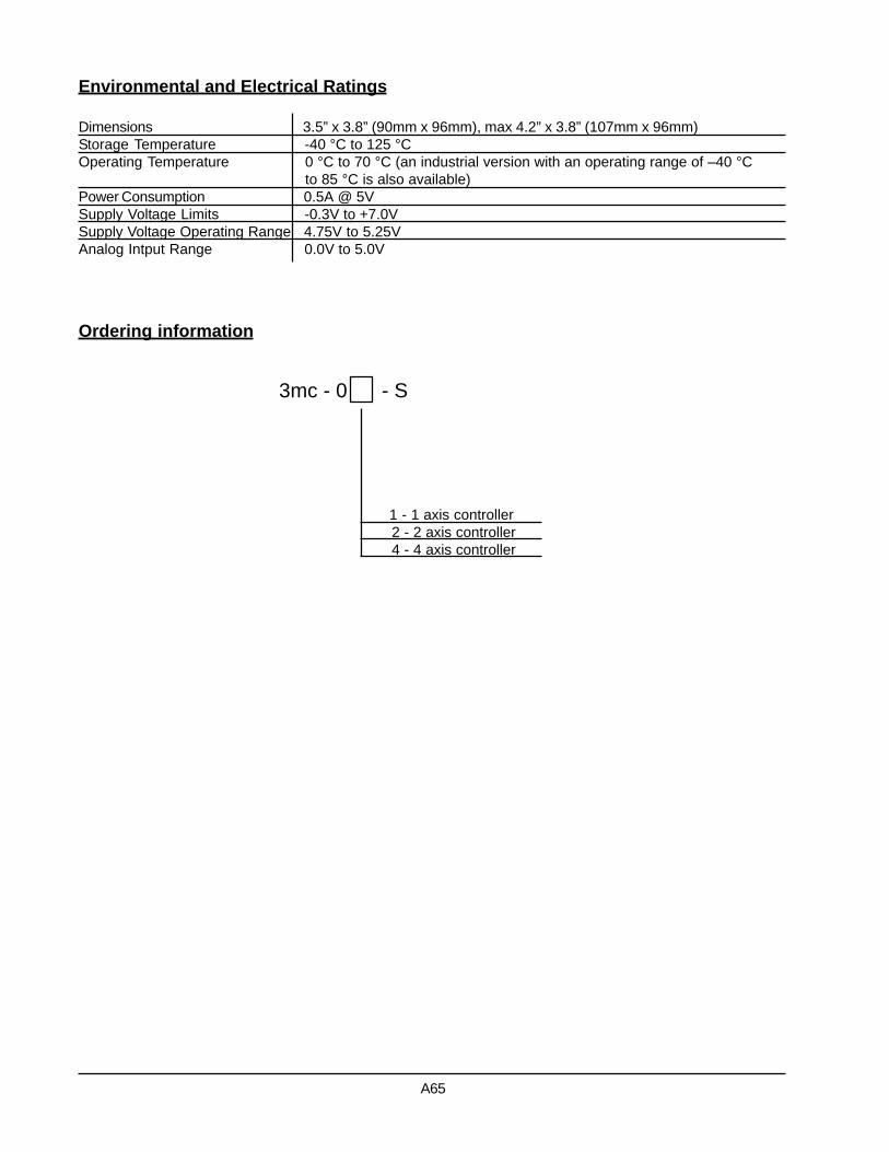
Environmental and Electrical Ratings
Dimensions 3.5” x 3.8” (90mm x 96mm), max 4.2” x 3.8” (107mm x 96mm)Storage Temperature -40 °C to 125 °COperating Temperature 0 °C to 70 °C (an industrial version with an operating range of –40 °C
to 85 °C is also available)Power Consumption 0.5A @ 5VSupply Voltage Limits -0.3V to +7.0VSupply Voltage Operating Range 4.75V to 5.25VAnalog Intput Range 0.0V to 5.0V
Ordering information
3mc - 0 - S
1 - 1 axis controller 2 - 2 axis controller 4 - 4 axis controller
A65

Product Description
The Millennium brush type multi-axis motion control-lers model 3m-0x-B implement the Navigator MC21xxseries chipsets - dedicated motion processors. Thesecontrollers harness the power of the Navigator high-speedDSP chip and incorporate ASIC and surface mount tech-nologies. They can install directly into a PC AT slot (ISAbus compatible) or can work standalone communicatingvia a serial link. The Millennium controllers are availablein configurations of 1, 2 or 4 axes.
The DSP unit provides S-curve, trapezoidal, velocitycontouring and electronic gearing profiling modes forAnalog or PWM signal output. Onboard memory al-lows designers to capture on-the-fly motion data foranalyzing system performance, tuning servo filters anddiagnostic purposes. Motion trajectory segments canbe blended into continuous motion path in the velocitymode.
The boards interface to external components via a 100pin high density connector providing motor outputs andreading pulsed encoder (incremental or absolute), limitswitches and home indicator input signals. They arecapable of handling eight analog inputs and eight user-defined discrete I/Os.
The cards are supported by C-MotionPlus™ andCyberMotion™ - extensive C-language software librar-ies and Windows and Linux drivers, which allow devel-opment of any motion control application. EasyMotion™,a GUI application package with the industry’s first everMotionWizard, assists in a quick and easy way to setup and tune even complex electro-mechanical systems.
The boards can be used in a variety of industries, suchas robotic, machine tool, semiconductor, medical, foodprocessing, textile and many others.
ISA-bus Millennium Series Motion Controller BoardFor Brush Servomotors
3m-0x-B
A66
C i t oS y s t e m s

Features:
Uses DSP and ASIC high speed dedicated motion processors in 1, 2 or 4 axes configurationIndependent or synchronous axes programmingOpen or closed servo loop operating modesAdvanced PID filter with velocity and acceleration feedforward, bias offset and 32-bit position errorAxis settled indicator and tracking window in addition to automatic motion error detectionChoice of S-curve, trapezoidal, velocity contouring or electronic gearing motion profilesAsymmetric acceleration and deceleration to custom program a trapezoidal motion profileVelocity and acceleration changes on-the-fly for trapezoidal and velocity contouring profilesPosition range from –2,147,483,648 to +2,147,483,647 countsVelocity range from -32,768 to +32,767 counts/sample with a resolution of 1/65,536 counts/sample invelocity contouring profile mode or from 0 to 32,767 counts/sample with a resolution of 1/65,536counts/sample in all other modesAcceleration and deceleration range from –32,768 to 32,767 counts/sample2 with a resolution of1/65,536 counts/sample2
Jerk range from 0 to 1 counts/sample3 with a resolution of 1/4,294,967,296 counts/sample3
Electronic gear ratio range from –32,768 to 32,767 (negative and positive direction)Programmable sample rate from 100 µsec to 3355 msec per axisMaximum incremental encoder rate up to 5.0 Mcounts/secMaximum parallel feedback device rate up to 160.0 Mcounts/secParallel feedback device word size: 16 bits+/-10V 16-bit DAC output signalPWM motor output signal of 10-bit resolution at 20 kHzOn-board 256 kByte memory buffer for data and parameters storageParallel or serial communication interfaceTwo-directional travel limit switches, home indicator and fault input per axisAutomatic motor shutdown on motion error8 general purpose 10-bit analog inputs in range of 0 to 5.0 V dc8 general purpose discrete inputs and outputs expandable to 256 inputs and 128 outputsProgrammable host interruptsTrace capabilities for system performance testing, servo-filter tuning and diagnostic purposesSoftware functions support coordinated linear and circular interpolation, point-to-point positioning andcontouring, backlash compensation, jogging, homing, etc.Status reporting for position, speed and errorsInfinite number of linear and arc segments for smooth motionProgrammable event triggers for monitoring elapsed time, motion complete, position, motion error, limitswitches and position wrap-around
A67

01 QuadA1+02 QuadA1-03 QuadB1+04 QuadB1-05 Index1+06 Index1-07 Vcc (encoder)08 GND (encoder)09 Not used10 Not used11 Not used12 GND13 PosLim114 NegLim115 Home116 AxisIn117 AxisOut118 PWMMag119 Not used20 Not used21 PWMsign122 DAC123 Not used24 GND (DAC)25 N.C.
26 QuadA2+27 QuadA2-28 QuadB2+29 QuadB2-30 Index2+31 Index2-32 Vcc (encoder)33 GND (encoder)34 Not used35 Not used36 Not used37 GND38 PosLim239 NegLim240 Home241 AxisIn242 AxisOut243 PWMMag244 Not used45 Not used46 PWMsign247 DAC248 Not used49 GND (DAC)50 N.C.
51 QuadA3+52 QuadA3-53 QuadB3+54 QuadB3-55 Index3+56 Index3-57 Vcc (encoder)58 GND (encoder)59 Not used60 Not used61 Not used62 GND63 PosLim364 NegLim365 Home366 AxisIn367 AxisOut368 PWMMag369 Not used70 Not used71 PWMsign372 DAC373 Not used74 GND (DAC)75 N.C.
76 QuadA4+77 QuadA4-78 QuadB4+79 QuadB4-80 Index4+81 Index4-82 Vcc (encoder)83 GND (encoder)84 Not used85 Not used86 Not used87 GND88 PosLim489 NegLim490 Home491 AxisIn492 AxisOut493 PWMMag494 Not used95 Not used99 PWMsign497 DAC498 Not used99 GND (DAC)100 N.C.
Pin Signal Name Pin Signal Name Pin Signal Name Pin Signal Name
Axes Control Signals Connector (J7)
01 PrlIn002 PrlOut003 PrlIn104 PrlOut105 PrlIn206 PrlOut207 PrlIn308 PrlOut309 PrlIn410 PrlOut4
User-defined Digital I/O Connector (J8)
11 PrlIn512 PrlOut513 PrlIn614 PrlOut615 PrlIn716 PrlOut717 GND18 Vcc19 GND20 Vcc
Pin Signal Name Pin Signal Name
01 Analog102 Analog203 Analog304 Analog405 Analog506 Analog607 Analog708 Analog809 AnalogIn110 AnalogIn211 AnalogIn312 AnalogIn413 AnalogRefHigh
Analog Input Connector (J9)
14 AnalogRefLow15 AnalogGND16 AnalogGND17 AnalogVcc18 GND19 GND20 Vcc21 AxisOut122 AxisOut223 AxisOut324 AxisOut425 Watchdog26 ~HostIntrpt
Pin Signal Name Pin Signal Name
01 SrlXmt02 SrlRcv03 Synch04 GND05 Vcc
01 +12V02 GND03 -12V
Pin Signal Name
Pin Signal Name
Serial Channel Connector (J4)
12V Power Connector (J10)
A68

Environmental and Electrical Ratings
Dimensions 4.8” x 10.0”, 16-bit ISA AdapterStorage Temperature -40 °C to 125 °COperating Temperature 0 °C to 70 °C (an industrial version with an operating range of –40 °C
to 85 °C is also available)Power Consumption 1A @ 5V; 83mA @ +/-12VSupply Voltage Limits -0.3V to +7.0VSupply Voltage Operating Range 4.75V to 5.25VAnalog Output Range -10.0V to 10.0VAnalog Input Range 0.0V to 5.0V
Ordering information
3m - 0 - B
A - analog output signalP - PWM output signal
1 - 1 axis controller2 - 2 axis controller4 - 4 axis controller
A69

Product Description
The Millennium brushless type multi-axis motion con-trollers model 3m-0x-BL implement the NavigatorMC23xx series chipsets - dedicated motion processorsfrom PMD. These controllers harness the power of theNavigator high-speed DSP chip and incorporate ASICand surface mount technologies. They can install di-rectly into a PC AT slot (ISA bus compatible) or canwork standalone communicating via a serial link. TheMillennium controllers are available in configurationsof 1, 2 or 4 axes.
The DSP unit provides S-curve, trapezoidal, velocitycontouring and electronic gearing profiling modes forAnalog or PWM signal output. Onboard memory al-lows designers to capture on-the-fly motion data foranalyzing system performance, tuning servo filters anddiagnostic purposes. Motion trajectory segments canbe blended into continuous motion path in the velocitymode.
The boards interface to external components via a 100pin high density connector providing motor outputs andreading pulsed encoder (incremental or absolute), limitswitches and home indicator input signals. They arecapable of handling eight analog inputs and eight user-defined discrete I/Os.
The card is supported by C-MotionTM - extensive C-language software libraries and Windows drivers, whichallow development of any motion control application.EasyMotionTM, a Windows application package with theindustry’s first ever MotionWizard, assists in a quickand easy way to set up and tune even complex electro-mechanical systems.
The boards can be used in a variety of industries, suchas robotic, machine tool, semiconductor, medical, foodprocessing, textile and many others.
ISA-bus Millennium SeriesMotion Controller BoardFor Brushless Servomotors
A70
3m-0x-BL
C i t oS y s t e m s

Features:
Uses DSP and ASIC high speed dedicated motion processors in 1, 2 or 4 axes configurationSupports 2 or 3-phase brushless motors6-step (Hall based) or sinusoidal commutationIndependent or synchronous axes programmingOpen or closed servo loop operating modesAdvanced PID filter with velocity and acceleration feedforward, bias offset and 32-bit position errorAxis settled indicator and tracking window in addition to automatic motion error detectionChoice of S-curve, trapezoidal, velocity contouring or electronic gearing motion profilesAsymmetric acceleration and deceleration to custom program a trapezoidal motion profileVelocity and acceleration changes on-the-fly for trapezoidal and velocity contouring profilesPosition range from –2,147,483,648 to +2,147,483,647 countsVelocity range from -32,768 to +32,767 counts/sample with a resolution of 1/65,536 counts/sample invelocity contouring profile mode or from 0 to 32,767 counts/sample with a resolution of 1/65,536counts/sample in all other modesAcceleration and deceleration range from –32,768 to 32,767 counts/sample2 with a resolution of1/65,536 counts/sample2
Jerk range from 0 to 1 counts/sample3 with a resolution of 1/4,294,967,296 counts/sample3
Electronic gear ratio range from –32,768 to 32,767 (negative and positive direction)Programmable sample rate from 150 µsec to 3355 msec per axisMaximum incremental encoder rate up to 5.0 Mcounts/secMaximum parallel feedback device rate up to 160.0 Mcounts/secParallel feedback device word size: 16 bits3 Hall effect input signals per axis (TTL level)Commutation rate 10 kHz for 4 axes or 20 kHz for 1 and 2 axes+/-10V 16-bit DAC output signalPWM motor output signal of 10-bit resolution at 20 kHz (1 or 2 axes) or 10-bit resolution at 10 kHz(4 axes) – 50/50 PWM mode supports 2 or 3 phase motors, Sign/Magnitude PWM mode supports2 phase motors onlyOn-board 256 kByte memory buffer for data and parameters storageParallel or serial communication interfaceTwo-directional travel limit switches, home indicator and fault input per axisAutomatic motor shutdown on motion error8 general purpose 10-bit analog inputs in range of 0 to 5.0 V dc8 general purpose discrete inputs and outputs expandable to 256 inputs and 128 outputsProgrammable host interruptsTrace capabilities for system performance testing, servo-filter tuning and diagnostic purposesSoftware functions support coordinated linear and circular interpolation, point-to-point positioningand contouring, backlash compensation, jogging, homing, etc.Status reporting for position, speed and errorsInfinite number of linear and arc segments for smooth motionProgrammable event triggers for monitoring elapsed time, motion complete, position, motion error,limit switches and position wrap-around
A71

01 QuadA1+02 QuadA1-03 QuadB1+04 QuadB1-05 Index1+06 Index1-07 Vcc (encoder)08 GND (encoder)09 Hall1A10 Hall1B11 Hall1C12 GND (Hall)13 PosLim114 NegLim115 Home116 AxisIn117 AxisOut118 PWMMagA119 PWMMagB120 PWMMagC121 Not used22 DACA123 DACB124 GND (DAC)25 N.C.
26 QuadA2+27 QuadA2-28 QuadB2+29 QuadB2-30 Index2+31 Index2-32 Vcc (encoder)33 GND (encoder)34 Hall2A35 Hall2B36 Hall2C37 GND (Hall)38 PosLim239 NegLim240 Home241 AxisIn242 AxisOut243 PWMMagA244 PWMMagB245 PWMMagC246 Not used47 DACA248 DACB249 GND (DAC)50 N.C.
51 QuadA3+52 QuadA3-53 QuadB3+54 QuadB3-55 Index3+56 Index3-57 Vcc (encoder)58 GND (encoder)59 Hall3A60 Hall3B61 Hall3C62 GND (Hall)63 PosLim364 NegLim365 Home366 AxisIn367 AxisOut368 PWMMagA369 PWMMagB370 PWMMagC371 Not used72 DACA373 DACB374 GND (DAC)75 N.C.
76 QuadA4+77 QuadA4-78 QuadB4+79 QuadB4-80 Index4+81 Index4-82 Vcc (encoder)83 GND (encoder)84 Hall4A85 Hall4B86 Hall4C87 GND (Hall)88 PosLim489 NegLim490 Home491 AxisIn492 AxisOut493 PWMMagA494 PWMMagB495 PWMMagC499 Not used97 DACA498 DACB499 GND (DAC)100 N.C.
Pin Signal Name Pin Signal Name Pin Signal Name Pin Signal Name
Axes Control Signals Connector (J7)
01 PrlIn002 PrlOut003 PrlIn104 PrlOut105 PrlIn206 PrlOut207 PrlIn308 PrlOut309 PrlIn410 PrlOut4
User-defined Digital I/O Connector (J8)
11 PrlIn512 PrlOut513 PrlIn614 PrlOut615 PrlIn716 PrlOut717 GND18 Vcc19 GND20 Vcc
Pin Signal Name Pin Signal Name
01 Analog102 Analog203 Analog304 Analog405 Analog506 Analog607 Analog708 Analog809 AnalogIn110 AnalogIn211 AnalogIn312 AnalogIn413 AnalogRefHigh
Analog Input Connector (J9)
14 AnalogRefLow15 AnalogGND16 AnalogGND17 AnalogVcc18 GND19 GND20 Vcc21 AxisOut122 AxisOut223 AxisOut324 AxisOut425 Watchdog26 ~HostIntrpt
Pin Signal Name Pin Signal Name
01 SrlXmt02 SrlRcv03 Synch04 GND05 Vcc
01 +12V02 GND03 -12V
Pin Signal Name
Pin Signal Name
Serial Channel Connector (J4)
12V Power Connector (J10)
A72

Environmental and Electrical Ratings
Dimensions 4.8” x 10.0”, 16-bit ISA AdapterStorage Temperature -40 °C to 125 °COperating Temperature 0 °C to 70 °C (an industrial version with an operating range of –40 °C
to 85 °C is also available)Power Consumption 1A @ 5V; 83mA @ +/-12VSupply Voltage Limits -0.3V to +7.0VSupply Voltage Operating Range 4.75V to 5.25VAnalog Output Range -10.0V to 10.0VAnalog Input Range 0.0V to 5.0V
Ordering information
3m - 0 - BL
A - analog output signalP - PWM output signal
1 - 1 axis controller 2 - 2 axis controller 4 - 4 axis controller
A73

Product Description
The Millennium motion controllers - model 3m-0x-B/BL combine the ability to control both brush and brushlessservomotors. The user can designate which axes arebrush and which are brushless. These multi-axis cardsimplement the Navigator MC28xx series chipsets - dedi-cated motion processors from PMD. They harness thepower of the Navigator high-speed DSP chip and incor-porate ASIC and surface mount technologies. They caninstall directly into a PC AT slot (ISA bus compatible) orcan work standalone communicating via a serial link.The Millennium controllers are available in configurationsof 2 or 4 axes.
The DSP unit provides S-curve, trapezoidal, velocitycontouring and electronic gearing profiling modes forAnalog or PWM signal output. Onboard memory al-lows designers to capture on-the-fly motion data foranalyzing system performance, tuning servo filters anddiagnostic purposes. Motion trajectory segments canbe blended into continuous motion path in the velocity
mode.The boards interface to external components via a 100pin high density connector providing motor outputs andreading pulsed encoder (incremental or absolute), limitswitches and home indicator input signals. They arecapable of handling eight analog inputs and eight user-defined discrete I/Os.
The card is supported by C-MotionTM - extensive C-language software library and Windows drivers, whichallow development of any motion control application.EasyMotionTM, a Windows application package with theindustry’s first ever MotionWizard, assists in a quickand easy way to set up and tune even complex electro-mechanical systems.
The boards can be used in a variety of industries, suchas robotic, machine tool, semiconductor, medical, foodprocessing, textile and many others.
ISA-bus Millennium SeriesMotion Controller BoardFor Brush & Brushless Servomotors
A74
3m-0x-B/BL
C i t oS y s t e m s

Features:
Uses DSP and ASIC high speed dedicated motion processors in 2 or 4 axes configurationSupports single phase brushed and 2 or 3-phase brushless motors6-step (Hall based) or sinusoidal commutation of brushless motors onlyIndependent or synchronous axes programmingOpen or closed servo loop operating modesAdvanced PID filter with velocity and acceleration feedforward, bias offset and 32-bit position errorAxis settled indicator and tracking window in addition to automatic motion error detectionChoice of S-curve, trapezoidal, velocity contouring or electronic gearing motion profilesAsymmetric acceleration and deceleration to custom program a trapezoidal motion profileVelocity and acceleration changes on-the-fly for trapezoidal and velocity contouring profilesPosition range from –2,147,483,648 to +2,147,483,647 countsVelocity range from -32,768 to +32,767 counts/sample with a resolution of 1/65,536 counts/sample invelocity contouring profile mode or from 0 to 32,767 counts/sample with a resolution of 1/65,536counts/sample in all other modesAcceleration and deceleration range from –32,768 to 32,767 counts/sample2 with a resolution of1/65,536 counts/sample2
Jerk range from 0 to 1 counts/sample3 with a resolution of 1/4,294,967,296 counts/sample3
Electronic gear ratio range from –32,768 to 32,767 (negative and positive direction)Programmable sample rate from 150 µsec to 3355 msec per axisMaximum incremental encoder rate up to 5.0 Mcounts/secMaximum parallel feedback device rate up to 160.0 Mcounts/secParallel feedback device word size: 16 bits3 Hall effect input signals per axis (TTL level) for brushless motors onlyCommutation rate 10 kHz for 4 axes or 20 kHz for 2 axes+/-10V 16-bit DAC output signalPWM motor output signal of 10-bit resolution at 20 kHz – 50/50 PWM mode supports 1, 2 or 3 phasemotors, Sign/Magnitude PWM mode supports 1 or 2 phase motors onlyOn-board 256 kByte memory buffer for data and parameters storageParallel or serial communication interfaceTwo-directional travel limit switches, home indicator and fault input per axisAutomatic motor shutdown on motion error8 general purpose 10-bit analog inputs in range of 0 to 5.0 V dc8 general purpose discrete inputs and outputs expandable to 256 inputs and 128 outputsProgrammable host interruptsTrace capabilities for system performance testing, servo-filter tuning and diagnostic purposesSoftware functions support coordinated linear and circular interpolation, point-to-point positioningand contouring, backlash compensation, jogging, homing, etc.Status reporting for position, speed and errorsInfinite number of linear and arc segments for smooth motionProgrammable event triggers for monitoring elapsed time, motion complete, position, motion error,limit switches and position wrap-around
A75

01 QuadA1+02 QuadA1-03 QuadB1+04 QuadB1-05 Index1+06 Index1-07 Vcc (encoder)08 GND (encoder)09 Hall1A*10 Hall1B*11 Hall1C*12 GND (Hall)13 PosLim114 NegLim115 Home116 AxisIn117 AxisOut118 PWMMagA119 PWMMagB1*20 PWMMagC1*21 Not used22 DACA123 DACB1*24 GND (DAC)25 N.C.
26 QuadA2+27 QuadA2-28 QuadB2+29 QuadB2-30 Index2+31 Index2-32 Vcc (encoder)33 GND (encoder)34 Hall2A*35 Hall2B*36 Hall2C*37 GND (Hall)38 PosLim239 NegLim240 Home241 AxisIn242 AxisOut243 PWMMagA244 PWMMagB2*45 PWMMagC2*46 Not used47 DACA248 DACB2*49 GND (DAC)50 N.C.
51 QuadA3+52 QuadA3-53 QuadB3+54 QuadB3-55 Index3+56 Index3-57 Vcc (encoder)58 GND (encoder)59 Hall3A*60 Hall3B*61 Hall3C*62 GND (Hall)63 PosLim364 NegLim365 Home366 AxisIn367 AxisOut368 PWMMagA369 PWMMagB3*70 PWMMagC3*71 Not used72 DACA373 DACB3*74 GND (DAC)75 N.C.
76 QuadA4+77 QuadA4-78 QuadB4+79 QuadB4-80 Index4+81 Index4-82 Vcc (encoder)83 GND (encoder)84 Hall4A*85 Hall4B*86 Hall4C*87 GND (Hall)88 PosLim489 NegLim490 Home491 AxisIn492 AxisOut493 PWMMagA494 PWMMagB4*95 PWMMagC4*99 Not used97 DACA498 DACB4*99 GND (DAC)100 N.C.
Pin Signal Name Pin Signal Name Pin Signal Name Pin Signal Name
Axes Control Signals Connector (J7)
01 PrlIn002 PrlOut003 PrlIn104 PrlOut105 PrlIn206 PrlOut207 PrlIn308 PrlOut309 PrlIn410 PrlOut4
User-defined Digital I/O Connector (J8)
11 PrlIn512 PrlOut513 PrlIn614 PrlOut615 PrlIn716 PrlOut717 GND18 Vcc19 GND20 Vcc
Pin Signal Name Pin Signal Name
01 Analog102 Analog203 Analog304 Analog405 Analog506 Analog607 Analog708 Analog809 AnalogIn110 AnalogIn211 AnalogIn312 AnalogIn413 AnalogRefHigh
Analog Input Connector (J9)
14 AnalogRefLow15 AnalogGND16 AnalogGND17 AnalogVcc18 GND19 GND20 Vcc21 AxisOut122 AxisOut223 AxisOut324 AxisOut425 Watchdog26 ~HostIntrpt
Pin Signal Name Pin Signal Name
01 SrlXmt02 SrlRcv03 Synch04 GND05 Vcc
01 +12V02 GND03 -12V
Pin Signal Name
Pin Signal Name
Serial Channel Connector (J4)
12V Power Connector (J10)
A76
* - depends on user axes designation
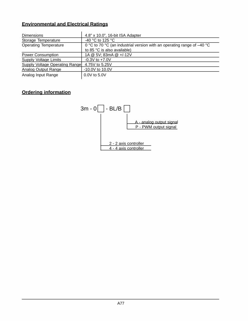
Environmental and Electrical Ratings
Dimensions 4.8” x 10.0”, 16-bit ISA AdapterStorage Temperature -40 °C to 125 °COperating Temperature 0 °C to 70 °C (an industrial version with an operating range of –40 °C
to 85 °C is also available)Power Consumption 1A @ 5V; 83mA @ +/-12VSupply Voltage Limits -0.3V to +7.0VSupply Voltage Operating Range 4.75V to 5.25VAnalog Output Range -10.0V to 10.0VAnalog Input Range 0.0V to 5.0V
Ordering information
3m - 0 - BL/B
A - analog output signalP - PWM output signal
2 - 2 axis controller 4 - 4 axis controller
A77

Product Description
The Millennium microstepping type multi-axis motioncontrollers model 3m-0x-MS implement the NavigatorMC24xx series chipsets - dedicated motion processorsfrom PMD. These controllers harness the power of theNavigator high-speed DSP chip and incorporate ASICand surface mount technologies. They can install di-rectly into a PC AT slot (ISA bus compatible) or canwork standalone communicating via a serial link. TheMillennium controllers are available in configurationsof 1, 2 or 4 axes.
The DSP unit provides S-curve, trapezoidal, velocitycontouring and electronic gearing profiling modes forAnalog or PWM signal output. Onboard memory al-lows designers to capture on-the-fly motion data foranalyzing system performance and diagnostic pur-poses. Motion trajectory segments can be blended intocontinuous motion path in the velocity mode.The boards interface to external components via a 100
pin high density connector providing motor outputs andreading pulsed encoder (incremental or absolute) foron-the-fly motor stall detection, limit switches and homeindicator input signals. They are capable of handlingeight analog inputs and eight user-defined discrete I/Os.
The card is supported by C-MotionTM - extensive C-language software libraries and Windows drivers, whichallow development of any motion control application.EasyMotionTM, a Windows application package with theindustry’s first ever MotionWizard, assists in a quickand easy way to set up even complex electro-mechani-cal systems.
The boards can be used in a variety of industries, suchas robotic, machine tool, semiconductor, medical, foodprocessing, textile and many others.
ISA-bus Millennium SeriesMotion Controller BoardFor Microstepping Motors
A78
3m-0x-MS
C i t oS y s t e m s
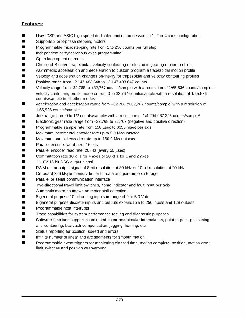
Features:
Uses DSP and ASIC high speed dedicated motion processors in 1, 2 or 4 axes configurationSupports 2 or 3-phase stepping motorsProgrammable microstepping rate from 1 to 256 counts per full stepIndependent or synchronous axes programmingOpen loop operating modeChoice of S-curve, trapezoidal, velocity contouring or electronic gearing motion profilesAsymmetric acceleration and deceleration to custom program a trapezoidal motion profileVelocity and acceleration changes on-the-fly for trapezoidal and velocity contouring profilesPosition range from –2,147,483,648 to +2,147,483,647 countsVelocity range from -32,768 to +32,767 counts/sample with a resolution of 1/65,536 counts/sample invelocity contouring profile mode or from 0 to 32,767 counts/sample with a resolution of 1/65,536counts/sample in all other modesAcceleration and deceleration range from –32,768 to 32,767 counts/sample2 with a resolution of1/65,536 counts/sample2
Jerk range from 0 to 1/2 counts/sample3 with a resolution of 1/4,294,967,296 counts/sample3
Electronic gear ratio range from –32,768 to 32,767 (negative and positive direction)Programmable sample rate from 150 µsec to 3355 msec per axisMaximum incremental encoder rate up to 5.0 Mcounts/secMaximum parallel encoder rate up to 160.0 Mcounts/secParallel encoder word size: 16 bitsParallel encoder read rate: 20kHz (every 50 µsec)Commutation rate 10 kHz for 4 axes or 20 kHz for 1 and 2 axes+/-10V 16-bit DAC output signalPWM motor output signal of 8-bit resolution at 80 kHz or 10-bit resolution at 20 kHzOn-board 256 kByte memory buffer for data and parameters storageParallel or serial communication interfaceTwo-directional travel limit switches, home indicator and fault input per axisAutomatic motor shutdown on motor stall detection8 general purpose 10-bit analog inputs in range of 0 to 5.0 V dc8 general purpose discrete inputs and outputs expandable to 256 inputs and 128 outputsProgrammable host interruptsTrace capabilities for system performance testing and diagnostic purposesSoftware functions support coordinated linear and circular interpolation, point-to-point positioningand contouring, backlash compensation, jogging, homing, etc.Status reporting for position, speed and errorsInfinite number of linear and arc segments for smooth motionProgrammable event triggers for monitoring elapsed time, motion complete, position, motion error,limit switches and position wrap-around
A79

01 QuadA1+02 QuadA1-03 QuadB1+04 QuadB1-05 Index1+06 Index1-07 Vcc (encoder)08 GND (encoder)09 N.C.10 N.C.11 N.C.12 GND13 PosLim114 NegLim115 Home116 AxisIn117 AxisOut118 PWMMagA119 PWMMagB120 PWMSignA121 PWMSignB122 DACA123 DACB124 GND (DAC)25 N.C.
26 QuadA2+27 QuadA2-28 QuadB2+29 QuadB2-30 Index2+31 Index2-32 Vcc (encoder)33 GND (encoder)34 N.C.35 N.C.36 N.C.37 GND38 PosLim239 NegLim240 Home241 AxisIn242 AxisOut243 PWMMagA244 PWMMagB245 PWMSignA246 PWMSignB247 DACA248 DACB249 GND (DAC)50 N.C.
51 QuadA3+52 QuadA3-53 QuadB3+54 QuadB3-55 Index3+56 Index3-57 Vcc (encoder)58 GND (encoder)59 N.C.60 N.C.61 N.C.62 GND63 PosLim364 NegLim365 Home366 AxisIn367 AxisOut368 PWMMagA369 PWMMagB370 PWMSignA371 PWMSignB372 DACA373 DACB374 GND (DAC)75 N.C.
76 QuadA4+77 QuadA4-78 QuadB4+79 QuadB4-80 Index4+81 Index4-82 Vcc (encoder)83 GND (encoder)84 N.C.85 N.C.86 N.C.87 GND88 PosLim489 NegLim490 Home491 AxisIn492 AxisOut493 PWMMagA494 PWMMagB495 PWMSignA499 PWMSignB497 DACA498 DACB499 GND (DAC)100 N.C.
Pin Signal Name Pin Signal Name Pin Signal Name Pin Signal Name
Axes Control Signals Connector (J7)
01 PrlIn002 PrlOut003 PrlIn104 PrlOut105 PrlIn206 PrlOut207 PrlIn308 PrlOut309 PrlIn410 PrlOut4
User-defined Digital I/O Connector (J8)
11 PrlIn512 PrlOut513 PrlIn614 PrlOut615 PrlIn716 PrlOut717 GND18 Vcc19 GND20 Vcc
Pin Signal Name Pin Signal Name
01 Analog102 Analog203 Analog304 Analog405 Analog506 Analog607 Analog708 Analog809 AnalogIn110 AnalogIn211 AnalogIn312 AnalogIn413 AnalogRefHigh
Analog Input Connector (J9)
14 AnalogRefLow15 AnalogGND16 AnalogGND17 AnalogVcc18 GND19 GND20 Vcc21 AxisOut122 AxisOut223 AxisOut324 AxisOut425 Watchdog26 ~HostIntrpt
Pin Signal Name Pin Signal Name
01 SrlXmt02 SrlRcv03 Synch04 GND05 Vcc
01 +12V02 GND03 -12V
Pin Signal Name
Pin Signal Name
Serial Channel Connector (J4)
12V Power Connector (J10)
A80

Environmental and Electrical Ratings
Dimensions 4.8” x 10.0”, 16-bit ISA AdapterStorage Temperature -40 °C to 125 °COperating Temperature 0 °C to 70 °C (an industrial version with an operating range of –40 °C
to 85 °C is also available)Power Consumption 1A @ 5V; 83mA @ +/-12VSupply Voltage Limits -0.3V to +7.0VSupply Voltage Operating Range 4.75V to 5.25VAnalog Output Range -10.0V to 10.0VAnalog Input Range 0.0V to 5.0V
Ordering information
3m - 0 - MS
A - analog output signalP - PWM output signal
1 - 1 axis controller 2 - 2 axis controller 4 - 4 axis controller
A81

Product Description
The Millennium stepper motor multi-axis motion con-trollers model 3m-0x-MS implement the NavigatorMC25xx series chipsets - dedicated motion processorsfrom PMD. These controllers harness the power of theNavigator high-speed DSP chip and incorporate ASICand surface mount technologies. They can install di-rectly into a PC AT slot (ISA bus compatible) or canwork standalone communicating via a serial link. TheMillennium controllers are available in configurationsof 1, 2 or 4 axes.
The DSP unit provides S-curve, trapezoidal, velocitycontouring and electronic gearing profiling modes forpulse and direction signal output. Onboard memory al-lows designers to capture on-the-fly motion data foranalyzing system performance and diagnostic pur-poses. Motion trajectory segments can be blended intocontinuous motion path in the velocity mode.The boards interface to external components via a 100
pin high density connector providing motor outputs andreading pulsed encoder (incremental or absolute) foron-the-fly motor stall detection, limit switches and homeindicator input signals. They are capable of handlingeight analog inputs and eight user-defined discreteinputs and outputs.
The card is supported by C-MotionTM - extensive C-language software library and Windows drivers, whichallow development of any motion control application.EasyMotionTM, a Windows application package with theindustry’s first ever MotionWizard, assists in a quickand easy way to set up even complex electro-mechani-cal systems.
The boards can be used in a variety of industries, suchas robotic, machine tool, semiconductor, medical, foodprocessing, textile and many others.
ISA-bus Millennium SeriesMotion Controller Board
For Stepper Motors
A82
3m-0x-S
C i t oS y s t e m s

Features:
Uses DSP and ASIC high speed dedicated motion processors in 1, 2 or 4 axes configurationIndependent or synchronous axes programmingOpen loop or stall detection with encoder feedback operating modesChoice of S-curve, trapezoidal, velocity contouring or electronic gearing motion profilesAsymmetric acceleration and deceleration to custom program a trapezoidal motion profileVelocity and acceleration changes on-the-fly for trapezoidal and velocity contouring profilesPosition range from –2,147,483,648 to +2,147,483,647 countsVelocity range from -32,768 to +32,767 counts/sample with a resolution of 1/65,536 counts/sampleAcceleration and deceleration range from –32,768 to 32,767 counts/sample2 with a resolution of1/65,536 counts/sample2
Jerk range from 0 to 1/2 counts/sample3 with a resolution of 1/4,294,967,296 counts/sample3
Electronic gear ratio range from –32,768 to 32,767 (negative and positive direction)Programmable sample rate from 100 µsec to 3355 msec per axisMaximum incremental encoder rate up to 5.0 Mcounts/secMaximum parallel encoder rate up to 160.0 Mcounts/secParallel encoder word size: 16 bitsParallel encoder read rate: 20kHz (every 50 µsec)Pulse and direction motor output up to 4.98 M-pulses/secOn-board 256 kByte memory buffer for data and parameters storageParallel or serial communication interfaceTwo-directional travel limit switches, home indicator and fault input per axisAutomatic motor shutdown on motor stall detection8 general purpose 10-bit analog inputs in range of 0 to 5.0 V dc8 general purpose discrete inputs and outputs expandable to 256 inputs and 128 outputsProgrammable host interruptsTrace capabilities for system performance testing and diagnostic purposesSoftware functions support coordinated linear and circular interpolation, point-to-point positioningand contouring, backlash compensation, jogging, homing, etc.Status reporting for position, speed and errorsInfinite number of linear and arc segments for smooth motionProgrammable event triggers for monitoring elapsed time, motion complete, position, motion error,limit switches and position wrap-around
A83

01 QuadA1+02 QuadA1-03 QuadB1+04 QuadB1-05 Index1+06 Index1-07 Vcc (encoder)08 GND (encoder)09 N.C.10 N.C.11 N.C.12 GND13 PosLim114 NegLim115 Home116 AxisIn117 AxisOut118 Pulse119 N.C.20 N.C.21 Direction122 N.C.23 N.C.24 GND25 N.C.
26 QuadA2+27 QuadA2-28 QuadB2+29 QuadB2-30 Index2+31 Index2-32 Vcc (encoder)33 GND (encoder)34 N.C.35 N.C.36 N.C.37 GND38 PosLim239 NegLim240 Home241 AxisIn242 AxisOut243 Pulse244 N.C.45 N.C.46 Direction247 N.C.48 N.C.49 GND50 N.C.
51 QuadA3+52 QuadA3-53 QuadB3+54 QuadB3-55 Index3+56 Index3-57 Vcc (encoder)58 GND (encoder)59 N.C.60 N.C.61 N.C.62 GND63 PosLim364 NegLim365 Home366 AxisIn367 AxisOut368 Pulse369 N.C.70 N.C.71 Direction372 N.C.73 N.C.74 GND75 N.C.
76 QuadA4+77 QuadA4-78 QuadB4+79 QuadB4-80 Index4+81 Index4-82 Vcc (encoder)83 GND (encoder)84 N.C.85 N.C.86 N.C.87 GND88 PosLim489 NegLim490 Home491 AxisIn492 AxisOut493 Pulse494 N.C.95 N.C.99 Direction497 N.C.98 N.C.99 GND100 N.C.
Pin Signal Name Pin Signal Name Pin Signal Name Pin Signal Name
Axes Control Signals Connector (J7)
01 PrlIn002 PrlOut003 PrlIn104 PrlOut105 PrlIn206 PrlOut207 PrlIn308 PrlOut309 PrlIn410 PrlOut4
User-defined Digital I/O Connector (J8)
11 PrlIn512 PrlOut513 PrlIn614 PrlOut615 PrlIn716 PrlOut717 GND18 Vcc19 GND20 Vcc
Pin Signal Name Pin Signal Name
01 Analog102 Analog203 Analog304 Analog405 Analog506 Analog607 Analog708 Analog809 AnalogIn110 AnalogIn211 AnalogIn312 AnalogIn413 AnalogRefHigh
Analog Input Connector (J9)
14 AnalogRefLow15 AnalogGND16 AnalogGND17 AnalogVcc18 GND19 GND20 Vcc21 AxisOut122 AxisOut223 AxisOut324 AxisOut425 Watchdog26 ~HostIntrpt
Pin Signal Name Pin Signal Name
01 SrlXmt02 SrlRcv03 Synch04 GND05 Vcc
Pin Signal Name
Serial Channel Connector (J4)
A84

Environmental and Electrical Ratings
Dimensions 4.8” x 10.0”, 16-bit ISA AdapterStorage Temperature -40 °C to 125 °COperating Temperature 0 °C to 70 °C (an industrial version with an operating range of –40 °C
to 85 °C is also available)Power Consumption 1A @ 5VSupply Voltage Limits -0.3V to +7.0VSupply Voltage Operating Range 4.75V to 5.25VAnalog Intput Range 0.0V to 5.0V
Ordering information
3m - 0 - S
1 - 1 axis controller 2 - 2 axis controller 4 - 4 axis controller
A85

Software Section

Software Functions LibraryFor MC2xxx Series Chipsets
C-MotionPlus Functions LibraryC-MotionPlus library is written in ANSI C/C++ language. It contains low level motion functions that directly commu-nicate with the PMD MC2xxx series of motion processors. The functions are also down compatible with theMC1xxx processor series.
The library routines can be used in MS Windows, DOS or Linux environments. Based on these functions the usercan develop a set of sophisticated procedures for an advanced motion system. However, with these functions aloneone can already perform basic motion control.
The C-MotionPlus routines are organized by categories. They perform a direct axis motion parameter setup,download and upload servo filter gains, provide motion processor performance status and control many otherfunctions of brush, brushless, stepper and microstepper processor types.
Instructions Summary by Functional Category
Breakpoints and Interrupts
ClearInterrupt Reset interrupting lineGetBreakpoint Get breakpoint typeGetBreakpointValue Get breakpoint comparison valueGetInterruptAxis Get the axes with pending interruptsGetInterruptMask Get interrupt maskSetBreakpoint Set breakpoint typeSetBreakpointValue Set breakpoint comparison valueSetInterruptMask Set interrupt mask
Commutation
GetCommutationMode Get the commutation modeGetNumberPhases Get the number of phasesGetPhaseAngle Get current commutation phase angleGetPhaseCommand Get the motor output command for a given phase A, B or CGetPhaseCorrectionMode Get phase correction modeGetPhaseCounts Get number of encoder counts per commutation cycleGetPhaseInitializeMode Get phase initialization modeGetPhaseInitializeTime Get the time parameters for the algorithmic phase initializationGetPhaseOffset Get phase offset valueGetPhasePrescale Get phasing prescalerInitializePhase Perform phase initialization procedureSetCommutationMode Set the commutation mode (Hall-based, sinusoidal or microstepping)SetNumberPhases Set the number of phases (1, 2 or 3)SetPhaseAngle Set current commutation phase angleSetPhaseCorrectionMode Set phase correction mode (on or off)SetPhaseCounts Set number of encoder counts per commutation cycleSetPhaseInitializeMode Set phase initialization method (Hall-based or algorithmic)SetPhaseInitializeTime Set the time parameters for algorithmic phase initializationSetPhaseOffset Set phase offset valueSetPhasePrescale Set commutation prescaler mode (enable or disable)
B1
C i t oS y s t e m s
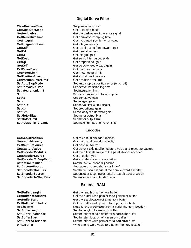
Digital Servo Filter
ClearPositionError Set position error to 0GetAutoStopMode Get auto stop modeGetDerivative Get the derivative of the error signalGetDerivativeTime Get derivative sampling timeGetIntegral Get integrated position error valueGetIntegrationLimit Get integration limitGetKaff Get acceleration feedforward gainGetKd Get derivative gainGetKi Get integral gainGetKout Get servo filter output scalerGetKp Get proportional gainGetKvff Get velocity feedforward gainGetMotorBias Get motor output biasGetMotorLimit Get motor output limitGetPositionError Get actual position errorGetPositionErrorLimit Get position error limitSetAutoStopMode Set auto stop on position error (on or off)SetDerivativeTime Set derivative sampling timeSetIntegrationLimit Set integration limitSetKaff Set acceleration feedforward gainSetKd Set derivative gainSetKi Set integral gainSetKout Set servo filter output scalerSetKp Set proportional gainSetKvff Set velocity feedforward gainSetMotorBias Set motor output biasSetMotorLimit Set motor output limitSetPositionErrorLimit Set maximum position error limit
Encoder
GetActualPosition Get the actual encoder positionGetActualVelocity Get the actual encoder velocityGetCaptureSource Get capture sourceGetCaptureValue Get current axis position capture value and reset the captureGetEncoderModulus Get the full scale range of the parallel-word encoderGetEncoderSource Get encoder typeGetEncoderToStepRatio Get encoder count to step rationSetActualPosition Set the actual encoder positionSetCaptureSource Set capture source (home or index)SetEncoderModulus Set the full scale range of the parallel-word encoderSetEncoderSource Set encoder type (incremental or 16-bit parallel word)SetEncoderToStepRatio Set encoder count to step ratio
External RAM
GetBufferLength Get the length of a memory bufferGetBufferReadIndex Get the buffer read pointer for a particular bufferGetBufferStart Get the start location of a memory bufferGetBufferWriteIndex Get the buffer write pointer for a particular bufferReadBuffer Read a long word value from a buffer memory locationSetBufferLength Set the length of a memory bufferSetBufferReadIndex Set the buffer read pointer for a particular bufferSetBufferStart Set the start location of a memory bufferSetBufferWriteIndex Set the buffer write pointer for a particular bufferWriteBuffer Write a long word value to a buffer memory location
B2
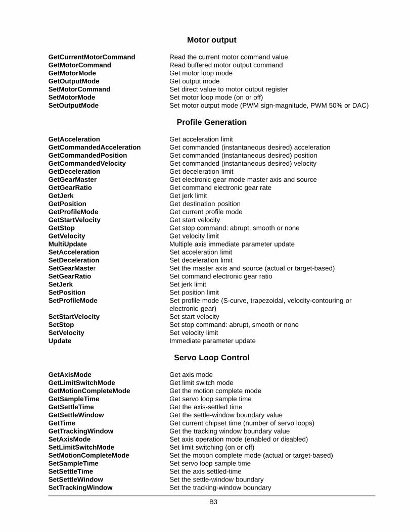
Motor output
GetCurrentMotorCommand Read the current motor command valueGetMotorCommand Read buffered motor output commandGetMotorMode Get motor loop modeGetOutputMode Get output modeSetMotorCommand Set direct value to motor output registerSetMotorMode Set motor loop mode (on or off)SetOutputMode Set motor output mode (PWM sign-magnitude, PWM 50% or DAC)
Profile Generation
GetAcceleration Get acceleration limitGetCommandedAcceleration Get commanded (instantaneous desired) accelerationGetCommandedPosition Get commanded (instantaneous desired) positionGetCommandedVelocity Get commanded (instantaneous desired) velocityGetDeceleration Get deceleration limitGetGearMaster Get electronic gear mode master axis and sourceGetGearRatio Get command electronic gear rateGetJerk Get jerk limitGetPosition Get destination positionGetProfileMode Get current profile modeGetStartVelocity Get start velocityGetStop Get stop command: abrupt, smooth or noneGetVelocity Get velocity limitMultiUpdate Multiple axis immediate parameter updateSetAcceleration Set acceleration limitSetDeceleration Set deceleration limitSetGearMaster Set the master axis and source (actual or target-based)SetGearRatio Set command electronic gear ratioSetJerk Set jerk limitSetPosition Set position limitSetProfileMode Set profile mode (S-curve, trapezoidal, velocity-contouring or
electronic gear)SetStartVelocity Set start velocitySetStop Set stop command: abrupt, smooth or noneSetVelocity Set velocity limitUpdate Immediate parameter update
Servo Loop Control
GetAxisMode Get axis modeGetLimitSwitchMode Get limit switch modeGetMotionCompleteMode Get the motion complete modeGetSampleTime Get servo loop sample timeGetSettleTime Get the axis-settled timeGetSettleWindow Get the settle-window boundary valueGetTime Get current chipset time (number of servo loops)GetTrackingWindow Get the tracking window boundary valueSetAxisMode Set axis operation mode (enabled or disabled)SetLimitSwitchMode Set limit switching (on or off)SetMotionCompleteMode Set the motion complete mode (actual or target-based)SetSampleTime Set servo loop sample timeSetSettleTime Set the axis settled-timeSetSettleWindow Set the settle-window boundarySetTrackingWindow Set the tracking-window boundary
B3

Status register and AxisOut Indicator
GetActivityStatus Get activity statusGetAxisOutSource Get axis out signal monitor sourceGetEventStatus Get event status wordGetSignal Get the current axis Signal Status registerGetSignalSense Get the interpretation of the Signal Status bitsResetEventStatus Reset bits in event status wordSetAxisOutSource Set axis out signal monitor sourceSetSignalSense Set the interpretation of the Signal Status bits
Traces
GetTraceCount Get the number of traced data pointsGetTraceMode Get the trace modeGetTracePeriod Get the trace periodGetTraceStart Get the trace start conditionGetTraceStatus Get the trace status wordGetTraceStop Get the trace stop conditionGetTraceVariable Get a trace variable settingSetTraceMode Set the trace mode (rolling or one-time)SetTracePeriod Set the trace periodSetTraceStart Start the traceSetTraceStop Stop the traceSetTraceVariable Set variable (i.e. data) to be traced
Miscellaneous
GetDiagnosticPortMode Get the diagnostic port valid instruction modeGetHostIOError Get the most recent I/O error modeGetSerialPort Read serial-port configuration dataGetVersion Get chipset software version informationNoOperation Perform no operation, used to verify communicationsReadIO Read user defined I/O valueReset Reset chipsetSetDiagnosticPortMode Set the diagnostic port valid instruction mode (limited or full)SetSerialPort Set serial-port configuration dataWriteIO Write user defined I/O value
B4

High PerformanceSoftware Library
CyberMotion Functions LibraryThe CyberMotion library is written in C, and supports the Microsoft Visual C++ development environment. Itcontains high-level procedures that take advantage of the PMD C-Motion low-level functions.
This library tremendously simplifies the development of user applications. It frees users from having to know thePMD motion processor functions in depth, which are tedious and time-consuming to work with. The libraryroutines can be used in the Windows or DOS environments, and allow the system designer to focus on thegraphical user interface. It provides a full set of functions to develop various controlled mechanical systems.
The CyberMotion routines are organized by categories. They perform the floating point calculations necessaryfor advanced motion of mechanical systems, set various system variables, and provide information about sys-tem behavior.The library supports the MC2xxx series of PMD motion processors.
Instructions Summary by Functional Category
Initialization ProceduresResetBoard Hardware reset.InitializeMotion Software system initialization.
System ConfigurationSetEncoderCountsPerRev Set a number of incremental quadrature encoder counts per revolution.GetEncoderCountsPerRev Get a number of incremental quadrature encoder counts per revolution.SetUnits Set the system of units – English, metric or encoder counts.GetUnits Get the currently defined system of units.UnitsRatio Define a ratio between encoder counts and linear units.SetUnitsToCounts Set a ratio between encoder counts and linear units.GetUnitsToCounts Get a ratio between encoder counts and linear units.CountsVelocity Download encoder counts velocity calculated from linear units.CountsAccel Download encoder counts acceleration calculated from linear units.SetPitch Set a pitch or mechanical gear ratio between rotary and linear motion.GetPitch Get the currently defined pitch or mechanical gear ratio.
Controller StatusGetChipsetStatus Get the current axis status.ClearChipsetStatus Clear the current axis status.
Motion StatusInMotion Check if an axis is still running.AllInMotion Check if all axes are still running.
Servo Filter ParametersSetFilterParams Set servo filter parameters.GetFilterParams Get servo filter parameters.DownloadFilterGains Download servo filter coefficients to the motion controller board.UploadFilterGains Upload servo filter coefficients from the motion controller board.
B5
C i t oS y s t e m s

Filter Feedback LoopCloseAxisLoop Clear the motion error and close the feedback loop.OpenAxisLoop Open the feedback loop.ServoOn Clear the motion error and close the feedback loop for all axes.ServoOff Open the feedback loop for all axes.
Axes ControlGetAxesQty Get a number of axes from the controller board.SetAxesQty Set the current number of axes.GetNewAxesQty Get the current number of axes.Axis Change an axis type from a character to a number.CharAxis Change an axis type from a number to a character.
MC1xxx series onlyGetCurrentAxis Get the current axis number from the controller.SetAxis Set the controller’s current axis defined by a character.IntAxis Set the controller’s current axis defined by a number.
MC2xxx series onlyGetPMDAxis Change an axis type from a number to the C-Motion type.GetPMDAxisHandle Change an axis type from a number to the C-Motion axis handle.GetCharAxisHandle Change an axis type from a character to the C-Motion axis handle.
Position ControlAxisActlCountsPos Upload actual encoder counts position.AxisActlPos Upload actual linear position.AxisActlCountsPosError Upload the actual encoder counts position error.AxisActlPosError Upload the actual linear position error.ZeroAxis Zero the position, velocity, acceleration and following error.ZeroAllAxes Zero the position, velocity, acceleration and following error of all axes.
Trajectory ControlSetVelocity Set linear velocity.GetVelocity Get linear velocity.SetAcceleration Set linear acceleration.GetAcceleration Get linear acceleration.
Motion Profile ModeSetProfileMode Set the motion profile mode.GetProfileMode Get the motion profile mode.SynchronizeChipsetProfile Clear the axis following error.DownloadProfileMode Download the motion profile mode to the controller.
Profiled MovesMoveToPositionIntrpt Begin a profiled move in counts ended by the interrupt signal.MoveToPositionPoll Begin a profiled move in counts. Loops while in motion.MoveOneAxis Begin a profiled move in linear units ended by the interrupt signal.MoveAxes Begin a profiled move of all axes.ExecTrapezoidalMove Perform a trapezoidal profile move.MoveEncoderAxis Move an axis to test the encoder feedback.
Interpolated MovesCircularIntrpl Execute 2-axis circular interpolated move.LinearIntrpl Execute 2 axis linear interpolated move.
B6

Jog Moves ControlCountsJogVelocity Download encoder counts jog velocity calculated from linear units.SetJogContinuous Set the jog mode as non- or continuous.GetJogContinuous Returns TRUE if the jog mode is continuous.SetJogBy Set the jog mode as non- or incremental.GetJogBy Returns TRUE if the jog mode is incremental.SetJogDestination Set a jog position value.GetJogDestination Get a jog position value.SetJogIncrement Set a jog increment value.GetJogIncrement Get a jog increment value.SetJogSpeed Set a jog feed rate value.GetJogSpeed Get a jog feed rate value.SetJogSpeedOverride Set a percentage change of the jog feed rate value.GetJogSpeedOverride Get a percentage change of the jog feed rate value.
Jog MovesSTARTJogging Begin a jog move in the given direction.STOPJogging Stop a jog move.
Stop MotionCloseMotion Stop the motion, shut off motor outputs and zero motion parameters.AxisAbruptStop Bring an axis to the immediate stop.
Motion ErrorsGetFollowingError Test if an axis move caused the position error.SetMotionErrorFlag Set the motion error flag for all axes.GetMotionErrorFlag Get the state of the motion error flag.
Motor OutputGetMotorType Get a motor type controlled by the motion controller.
MC1xxx series onlySetOutputMC1 Send the motor output signal mode to the controller board.SetOutSignalModeMC1 Set the motor output signal mode.GetOutSignalModeMC1 Get the motor output signal mode.
MC2xxx series onlySetOutputMC2 Send the motor output signal mode to the controller board.SetOutSignalModeMC2 Set the motor output signal mode.GetOutSignalModeMC2 Get the motor output signal mode.
Software LimitsSetSoftLimitMinus Set the negative software position limit.GetSoftLimitMinus Get the negative software position limit.SetSoftLimitPlus Set the positive software position limit.GetSoftLimitPlus Get the positive software position limit.SetSoftOvertravelMinus Set the logical state of the negative software position limit.GetSoftOvertravelMinus Get the logical state of the negative software position limit.SetSoftOvertravelPlus Set the logical state of the positive software position limit.GetSoftOvertravelPlus Get the logical state of the positive software position limit.SoftLimits Check if an axis remains within the software limits.
Hardware LimitsSetHighHardLmtMinus Set the active state of the negative hardware limit switch.GetHighHardLmtMinus Get the active state of the negative hardware limit switch.
B7

SetHighHardLmtPlus Set the active state of the positive hardware limit switch.GetHighHardLmtPlus Get the active state of the positive hardware limit switch.SetLimitsSense Set the active state of the hardware limit switches for all axes.GetLimitsSense Get the active state of the hardware limit switches for all axes.ActivateLimitSwitches Activate or deactivate axis hardware limit switches.SetLimitOn Activate or deactivate all axes hardware limit switches.GetLimitOn Get the limit switches state from the sensing mechanism.ResetHrdLimits Reset the active state of the hardware limit switches.
Home InputsSetHomingInPlus Define a direction of the homing move for the current homing axis.GetHomingInPlus Returns TRUE when an axis is homing in the positive direction.SetHomeSwitch Set the homing input to a limit switch or home switch.GetHomeSwitch Get a switch type used as the homing input.
Homing ParametersSetHomeOffset Set offset position from the home position.GetHomeOffset Get offset position from the home position.SetHomingSpeed Set homing move speed.GetHomingSpeed Get homing move speed.SetOffsetSpeed Set offset move speed.GetOffsetSpeed Get offset move speed.
Homing ProcedureGetHomingMode Check if the system is performing the homing procedure.HomeAxis Set an axis as the currently homing axis.SetAxesHomed Set TRUE when the axis homing process is finished.GetAxesHomed Check if all axes finished the homing procedure.
Counter/TimerMilisecDelay Define a delay in milliseconds.GetChipsetSampleTime Upload the servo filter sample rate from the controller.SetChipsetSampleTime Download the servo filter sample rate to the controller.
CNC FunctionsGetAbsolutePosition Get absolute position.TurnSpindleOff Turn the spindle motion off.SetSpindleSpeed Set a spindle rpm value.GetOffset Get offset registers values.SetOffsetIndex Set an index of the D Registers array.SetDRegisters Set D Registers values.GetDRegisters Get D Registers values.SetToolOffset Set tool offset position.GetToolOffset Gets tool offset position.Dwell Dwell for the specified time.
MiscellaneousSetControllerInstalled Set TRUE if the motion controller board is plugged in.GetControllerInstalled Returns TRUE if the motion controller board is plugged in.SetChipsetGen Set the PMD motion processor generation to MC1xxx or MC2xxx.GetChipsetGen Get the PMD motion processor generation as MC1xxx or MC2xxx.GetChipsetVersion Get the PMD motion processor version.GetLibraryVersion Get the CyberMotion library version.
B8
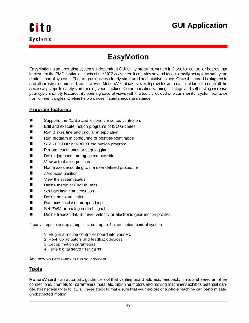
GUI Application
EasyMotionEasyMotion is an operating systems independant GUI utility program, written in Java, for controller boards thatimplement the PMD motion chipsets of the MC2xxx series. It contains several tools to easily set up and safely runmotion control systems. The program is very clearly structured and intuitive to use. Once the board is plugged inand all the wires connected, our first ever -MotionWizard takes over. It provides automatic guidance through all thenecessary steps to safely start running your machine. Communication warnings, dialogs and self-testing increaseyour system safety features. By opening several views with the tools provided one can monitor system behaviorfrom different angles. On-line help provides instantaneous assistance.
Program features:
Supports the Xantia and Millennium series controllersEdit and execute motion programs of ISO G-codesRun 2 axes line and circular interpolationRun program in contouring or point-to-point modeSTART, STOP or ABORT the motion programPerform continuous or step joggingDefine jog speed or jog speed overrideView actual axes positionHome axes according to the user defined procedureZero axes positionView the system statusDefine metric or English unitsSet backlash compensationDefine software limitsRun axes in closed or open loopSet PWM or analog control signalDefine trapezoidal, S-curve, velocity or electronic gear motion profiles
4 easy steps to set up a sophisticated up to 4 axes motion control system
1. Plug in a motion controller board into your PC2. Hook up actuators and feedback devices3. Set up motion parameters4. Tune digital servo filter gains
And now you are ready to run your system.
Tools
MotionWizard - an automatic guidance tool that verifies board address, feedback, limits and servo amplifierconnections, prompts for parameters input, etc. Spinning motors and moving machinery exhibits potential dan-ger. It is necessary to follow all these steps to make sure that your motors or a whole machine can perform safe,unobstructed motion.
B9
C i t oS y s t e m s

MotionScope - a graphical tool for tuning servo filter parameters. It is a 16 channel scope (4 sources ofdifferent signals for 4 axes of motion) with storage, trigger, frequency base, offset and gain features. The scopeprovides a very convenient way to play with the filter parameters and execute the step response in order toperform smooth motion.
MotionStatus - a tool providing constant display of the board status. Any problems with the systems can beinstantaneously monitored on a computer screen.
B10

CNC Readout - a special viewing tool that continuously displays machine’s X, Y, Z and W coordinates, jogparameters, feedrate and feedrate override. Large fonts help to view it from a large distance.
B11

Accessories

Product Description
The converter accepts input signals in the range 3 kHz– 20 kHz on the SIN, COS and REF inputs. A Type IIservo loop is employed to track the inputs and convertthe input SIN and COS information into a digital repre-sentation of the input angle. The bandwith of the con-verter is set internally at 1 kHz. Maximum tracking rateis 500 rps at 12-bit resolution. The converters are avail-able in configurations of 1, 2, 3 or 4 axes.
Angular position is available in a form of incremental A
Resolver-to-EncoderSignal Converter
RTE-0x
Features:
Incremental 1024 line (4096 quadrature counts) encoder emulation
Differential inputs12-bit resolutionAnalog Velocity Output (optional)Configuration of 1, 2, 3 or 4 axes
quad B. The encoder emulation outputs A, B and In-dex continuously produce signals equivalent to a 1024line (4096 quadrature counts) encoder.
An analog velocity output signal provides an accuraterepresentation of input angular velocity of the input sig-nals, in either a clockwise or counterclockwise direc-tion. The analog velocity output is scaled to produce150 rps/V dc +/- 15% and its maximum value is equiva-lent to +/- 375 rps.
C1
C i t oS y s t e m s

Pin Signal Name Signal Description
Resolver Signals Connector (J2, J4, J6 and J8)
01 VDD02 DGND03 VSS04 VASS05 VADD06 AGND
Pin Signal Name Signal Description
Power Connector (J1)
C2
Environmental and Electrical Ratings
Dimensions 4” x 4” (10mm x 10mm)Storage Temperature -40 °C to 125 °COperating Temperature 0 °C to 70 °CPower Consumption max 40mA @ 5V; 15mA @ 12VSupply Voltage Limits -0.3V to +7.0V, +/-5.0V to +/-15VSupply Voltage Operating Range 4.75V to 5.25V, +/-10V to +/-12VAnalog Output Range -12.0V to 12.0V
Ordering information
RTE - 0
01 AGND 02 REF
03 COS 04 COS LO 05 SIN LO 06 SIN
Digital groundEncoder A output. A leads B for increasing angular rotation.Encoder B output.Index signal – 90o wide (one per revolution)
Digital positive power supply, +5V dc +/- 5%Digital groundDigital negative power supply, -5V dc +/- 5%Analog negative power supply, -12V dc +/- 2VAnalog positive power supply, +12V dc +/- 2VAnalog ground
1 - 1 axis converter2 - 2 axis converter3 - 3 axis converter4 - 4 axis converter
Pin Signal Name Signal Description
Encoder Signals Connector (J3, J5, J7 and J9)
01 DGND 02 CH. A 03 CH. B 04 INDEX
Analog ground, REF groundConverter reference input connected to resolver primary excitation.Phase shift with reference to COS and SIN +/-10o max.COS channel non-inverting input connected to resolver COS HI.COS channel inverting input connected to resolver COS LO.SIN channel inverting input connected to resolver SIN LO.SIN channel non-inverting input connected to resolver SIN HI.

Product Description
The cable enables connection between a 100-pin highdensity on-board plug and 2 50-pin commonly usedIDH type male headers. It splits into 2 ribbons of whicheach of them handles 50 signals.
100 pin High Density to2x50 pin Connecting Cable
CAB-100/2x50
Features:
100-pin 0.050 mil pitch socketLatching eject mechanism facilitates matingand un-mating2x IDS type 50-pin 0.100 mil femaleconnectors2x 28 AWG ribbon cablesStandard cable length 3 ft. (914 mm)Custom length available3 dimensional mating
Ordering information
CAB-100/2x50-
specified cable length in feet
C3
The cable allows to easily interface between the mo-tion controller and an external interface board. Thecable length can be adjusted according to customerspecification.
C i t oS y s t e m s

In North America:Cito Systems3940 Freedom CircleSanta Clara, CA 95054USATel. (408) 836-3300Fax (408) 200-7499www.citosys.come-mail: [email protected]
In Central & Western Europe:Egmont Instrumentsul. Chlodna 39, pawilon 1100-867 WarszawaPolandTel. +48-22-850-6205Fax +48-22-654-0248www.egmont.com.ple-mail: [email protected]
In Scandinavia:Indutek ScandinaviaToftevej 10DK-3250 GillelejeDenmarkTel. +45-70-23-08-00Fax +45-70-23-88-00www.indutek.come-mail: [email protected]
Doc. # 1000500
C i t oS y s t e m s