motion control catalog 2006 - datasheet.octopart.com
TRANSCRIPT
onlinec
omponen
ts.co
m
Motion and Motor Control Solutions
Reliable, accurate positioning and motion control forseamless industrial automation
Stand-alone open platform motion controller Servo drives and motors
Energy-saving AC inverters PLC-based motion and position controllers Cam positioners and rotary encoders
MOTIO
NCON
TROL

onlinec
omponen
ts.co
m
Selection guide I-ii
Servo drives and motors
W-Series Full-featured servo system; advanced setup tools, diagnostics, and comm. I-5
SmartStep Economical, easy-to-use servo system ideal for stepper upgrades I-12
Inverters
3G3JV Compact AC inverter for simple motor control I-20
3G3MV Compact inverter offers Loop Vector and V/Hz control I-22
G5+ Flux vector inverter, 600V, constant torque (Canada only) I-25
P5+ Powerful 600V variable torque inverter (Canada only) I-28
RV Flux vector inverter, general-purpose and high-end applications (Canada only) I-30
Position controllers/high-speed counters
CJ1/CS1- PLC-based NC/-CT/ accurate-HC positioning control I-33
Motion controllers
CJ1/CS1 High-speed PLC-based -MC motion controllers I-37
Soft starters
G3JA 3-phase hybrid soft starters extend motor life I-39
Cam positioners
H8PS Stand-alone cam positioner uses encoder input I-41
C200H- PLC-based cam positioner CP114 uses resolver input I-43
ContentsRotary encoders
Absolute encoders
E6C3-A Water resistant encoder for tough environments I-44
E6CP Low-cost absolute encoder, 50 mm diameter I-45
E6F-A Rugged encoder for high-precision detections I-46
Incremental encoders
E6A2-C Miniature positioning solution for tight spaces I-47
E6B2-C General-purpose compact encoders I-48
E6C3-C Water resistant encoder for tough environments I-49
E6D Rugged, high-resolution encoder I-50
E6F-C Rugged encoder with strong shaft I-50
Motion/Motor Controls
I-i
I Div Motion 2 4/24/06 6:49 AM Page 1
TJ1-_ Trajexia Motion Controller, I-1

onlinec
omponen
ts.co
m
Motion Solutions Selection Guide
Servo Drives and Motors
R88D-WN
R88D-WT
MECHATROLINK II output
Analog output
I-ii
W-Series servo drives
FNY-NS115
R88A-NCW152-DRT
MECHATROLINK II for R88D-WT drives
DeviceNet adapter
W-Series servos networkcommunications adapters
R88A-CRW
R88A-RR
R88A-CAWPower cables
Encoder cables
R88A-PX
R88A-F1W or LF
DC reactors
AC reactors
External regenerative resistors
W-Series cylindricalservo motors
30 W to 15 kW; 3000, 1500, 1000 rpm; incremental or absoluteencoders; with or without brakes;
100 or 200 VAC; shaft optionsR88M-W
Configuration andmonitoring software
CX-Drive application in CX-ONE software CXONE
W-Series flat styleservo motors
100 W to 1.5 kW; 3000 rpm; incremental or absolute encoders;
with or without brakes; 100 or 200 VAC; shaft options
R88M-WP
Full-featuredservo system
withadvanced
setup toolsdiagnostics
and communications W-Series encoder and
power cables, accessories
09.Motn Rotary SelGd06 R3 3/30/06 2:34 PM Page 1

onlinec
omponen
ts.co
m
Motion Solutions Selection Guide
Servo Drives and Motors
I-iii
SmartStep servo drives Pulse output R7D-AP
SmartStep flat style servo motors
100 W to 750 W; 3000 rpm; with or without brakes;
100 or 200 VAC; shaft optionsR7M-AP
SmartStep cylindrical servo motors
30 W to 750 W; 3,000 rpm;incremental encoder; with or
without brakes; 100 or 200 VAC; shaft options
R7M-A
Configuration and monitoring software
CX-Drive application in CX-ONE software CXONE
R7A/R88A
R7A-CEA
Accessories
Power/encoder cables
SmartStep cables and accessories
Easy-to-set-up,
economicalservo
system ideal forstepper system
upgrades
Inverters No flux
vector control1/8 to 5 HP, 1-phase, 240 VAC 3-phase, 230 VAC or 460 VAC 3G3JV
Full flux vector control
1/2 to 40 HP, 3-phase, 230 VAC or 460 VAC 3G3RV
Sensor-less flux vector control
1/8 to 10 HP, 1-phase 240 VAC, 3-phase 230 VAC or 460 VAC 3G3MV
General purpose
applications
Sensor-less flux vector control
1/8 to 10 HP, 3-phase 230 VAC or 460 VAC 3G3MV (V7CU)Washdown
applications
Full flux vector control
1/2 to 40 HP, 3-phase,230 VAC or 460 VAC 3G3RVPumps
and fans
Flux vector control 2 to 200 HP, 3-phase, 600 V G5+
Constant torquefor machineautomation
Flux vector control 2 to 200 HP, 3-phase, 600 V P5+
Variable torquefor buildingautomation
09.Motn Rotary SelGd06 R3 3/30/06 2:34 PM Page 2

onlinec
omponen
ts.co
mBasic Plug-in unit, face-mount 3G3MV-P10CDT-E
3G3RV-P10ST8-E
3G3MV-P10CDT3-E
Embedded board,real-time clock/calendar
Plug-in unit, face-mount,real-time clock/calendar
Advanced functions
Motion Solutions Selection Guide
Inverters
3G3RV-PDRT2
3G3MV-PDRT2Monitor operations,
change settings
I-iv
DeviceNet slave unitFieldbusconnectivity
CS1W-NC113/133
CJ1W-NC113/133
CS1 PLC modules, pulse trainoutput for R88D-WT servo drives
CJ1 PLC modules, pulse trainoutput for R88D-WT servo drives
Omron PLC modules
CJ1W-NC213/233
CS1W-NC213/233
CJ1W-NC413/433
2 axes, CS1 PLC modules, pulse trainoutput, for R88D-WT servo drives
4 axes, CJ1 PLC modules, pulse trainoutput, for R88D-WT servo drives
2 axes, CJ1 PLC modules, pulse trainoutput, for R88D-WT servo drives
CS1W-NC413/4334 axes, CS1 PLC modules, pulse trainoutput, for R88D-WT servo drives
Omron PLC modules
Add-on PLC
option
Omron PLC module,MECHATROLINK II
network
16 axes, without synchronization,for R88D-WN servo drivers CS1W-NCF71
Single axisposition
controller
Position Controllers
Multi-axisposition
controller
09.Motn Rotary SelGd06 R3 3/30/06 2:34 PM Page 3

onlinec
omponen
ts.co
m
Motion Solutions Selection Guide
Motion Controllers
I-v
Stand-alone 4 or 16 axes w/open comm; connects to W-Series
(R88D-WT, R88D-WN) and SmartStep (R7D) servo drives
TJ1 (Trajexia)
CS1W-MC421-V1
CS1W-MC221-V1
4 axes, CS1 PLC module, analogoutput, for R88D-WT servo drives
2 axes, CS1 PLC module, analogoutput, for R88D-WT servo drives
Omron PLC modules
CS1W-MCH71
CJ1W-MCH71
30 axes, with synchronization,for R88D-WN servo drivers
30 axes, with synchronization, for R88D-WN servo drivers
Omron PLC modules,MECHATROLINK II
network
Multi-axismotion
controller
Motion Controllers Used with Servos and InvertersType Controller Servo Inverter
Stand-alone TJ1 (Trajexia) W-Series: R88D-WT servo drives 3G3MV/3G3RV
PLC module “-NC” modules or other W-Series: R88D-WT servo drives — controller with pulse train SmartStep: R7D servo drives
“-MC” modules or other W-Series: R88D-WT servo drives 3G3MV/3G3RVcontroller with analog output
PLC module CJ1W-NCF71 module W-Series: R88D-WN servo drives —with control over MECHATROLINK II “-MCH71” modules W-Series: R88D-WN servo drives 3G3MV/3G3RV
09.Motn Rotary SelGd06 R3 3/30/06 2:34 PM Page 4

onlinec
omponen
ts.co
mCS1W-CT0414 channels
2 channels
Configurable digital inputs+
outputs; target valuestrigger interrupt to CPU
500 kHzincremental
encoderinput
Motion Solutions Selection Guide
High-Speed Counter PLC Modules
I-vi
CS1W-CTS212 channels
Baud rate, encoding type,data length, etc. can be
set per channel
CJ1W-CTS21-E
SynchronousSerial
Protocol (SSP)input forabsolute
position data
Configurable digital inputs+
outputs; target valuestrigger interrupt to CPU
4 channels CJ1W-CTL41-E100 kHz
incrementalencoder input
Cam Positioners Emulate Mechanical Cam SwitchesAbsolute encoderinput: 1600 rpm 8, 16 or 32 outputs H8PSStand-alone
Resolver input:800 rpm 48 outputs C200H-CP114PLC module
Soft Starters Soft Start, Kick Start,
Current Limit Start, andSoft Stop functions
3-phase inductive motors G3JA-CMulti-function
Provides internalStar-delta control 3-phase, 6-lead motors G3JA-DCurrent
limit starter
CS1W-CT021
CJ1W-CT021
09.Motn Rotary SelGd06 R3 3/30/06 2:34 PM Page 5
onlinec
omponen
ts.co
m
I-vii
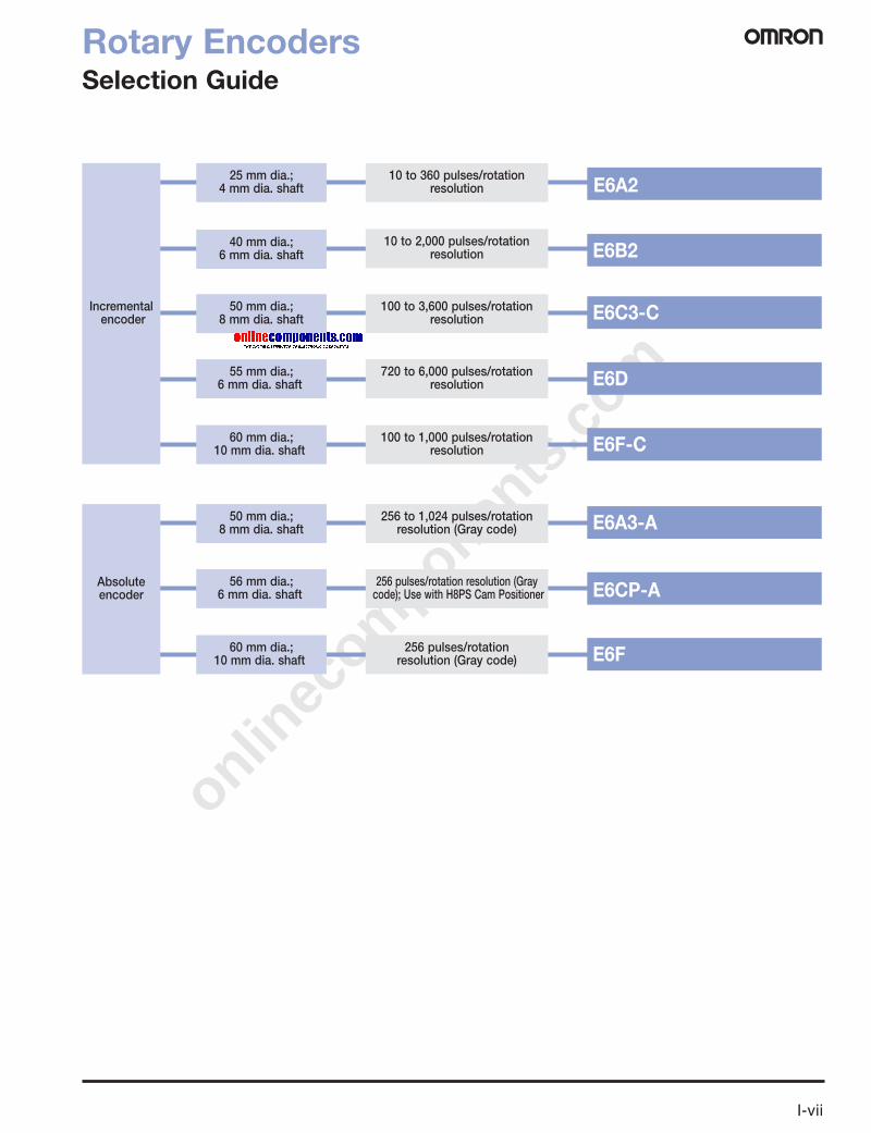
25 mm dia.; 4 mm dia. shaft
Rotary EncodersSelection Guide
E6D
E6C3-C
E6B2
E6A2
720 to 6,000 pulses/rotation resolution
100 to 1,000 pulses/rotation resolution
10 to 360 pulses/rotation resolution
10 to 2,000 pulses/rotation resolution
Incrementalencoder
50 mm dia.; 8 mm dia. shaft
60 mm dia.; 10 mm dia. shaft
40 mm dia.; 6 mm dia. shaft
55 mm dia.; 6 mm dia. shaft
100 to 3,600 pulses/rotation resolution
E6F-C
E6CP-A
E6A3-A
256 pulses/rotation resolution (Graycode); Use with H8PS Cam Positioner
256 pulses/rotation resolution (Gray code)
Absoluteencoder
50 mm dia.; 8 mm dia. shaft
60 mm dia.; 10 mm dia. shaft
56 mm dia.; 6 mm dia. shaft
256 to 1,024 pulses/rotation resolution (Gray code)
E6F
09.Motn Rotary SelGd06 R3 3/30/06 2:34 PM Page 6

onlinec
omponen
ts.co
m
I-1
TJ1-@ Trajexia Motion Controller
Stand-Alone Advanced Motion Controller Using Mechatrolink-II Motion Bus• 16 axes advanced motion coordination over a robust and fast
motion link MECHATROLINK-II• Supports position, speed and torque control• Each axis can run complex interpolation moves, e-cams and
e-gearboxes• Advanced debugging tools including trace and oscilloscope
functions• Hardware registration input for each servo axis• Control of servos, inverters and I/Os over a single motion
network• Multi-tasking controller capable of running up to 14 tasks
simultaneously• Open communication - Ethernet built-in, PROFIBUS-DP and
DeviceNet as options
System Configuration
Trajexia Motion Controller
TJ1-@ G031
M
CX-OneTrajexia tool
NS-seriesHMI
MECHATROLINK-II unit
Linear motors
16 axes max. Total lenght: 50 m
I/O module
PROFIBUS-DP
PROFIBUS-DP
Terminator
Servomotor
Servodrive
Input
Motion controller
CJ-series PLC
Digital I/Os
Host-link
Fast registration input, home
Ethernet
MECHATROLINK-II
Frequencyinverter

onlinec
omponen
ts.co
m
For complete specifications and additional models: U.S. www.omron247.com Canada www.omron.ca I-2
TJ1-@ Trajexia Motion Controller
Specifications
General Specifications
Motion Control Unit
Item DetailsModel TJ1-@Ambient operating temperature 0 to 55° CAmbient operating humidity 10 to 90% RHAmbient storage temperature –20 to 70° CAmbient storage humidity 90% max. (with no condensation)Atmosphere No corrosive gasesVibration resistance 10 to 57 Hz: (0.075 mm amplitude)
57 to 100 Hz Acceleration: 9.8 m/s2, in X, Y and Z directions for 80 minutesShock resistance 143 m/s2, 3 times each X, Y and Z directionsInsulation resistance 20 MOhmDielectric strength 500 VoltProtective structure IP20International standards cULus, CE, EN 61131-2 and RoHS
Item DetailsModel TJ1-MC16Number of axes 16Number of inverters and I/O modules 8 maximumNumber of Mechatrolink-II master units Up to 4 Mechatrolink-II master units (TJ1-ML16, see below) can be connectedCycle time Selectable 0.5 ms, 1 ms or 2 msProgramming language BASIC-like Motion languageMulti-tasking Up to 14 tasks running simultaneouslyDigital I/O 16 Inputs and 8 Outputs freely configurableMeasurement units User definableAvailable memory for user programs 500 kbData storage capacity Up to 2 MB flash data storageSaving program data, motion controller SRAM with battery backup and Flash-ROMSaving program data, personal computer Trajexia Motion Perfect software manages a backup on the hard disk of the personal computerCommunication ports 1 Ethernet port and 2 serial portsFirmware update Via Trajexia software toolEthernet port Electrical characteristics Conform to IEEE 802.3 (100BaseT)
Connector RJ45 Ethernet connectorSerial port Electrical characteristics Conform 1 port to RS-232C and 1 port to RS-485/RS-422A (selectable by switch)
Connector SUB-D9 connector (Counterpart included in the package)Synchronization Start-stop synchronization (asynchronous)Baud rate 1200 / 2400 / 4800 / 9600 / 19200 / 38400 bpsTransmission format Databit Length 7 or 8 bit
Stop bit 1 or 3 bitParity Bit Even/Odd/None
Transmission mode Point-to-multipoint (1:N)Transmission protocol RS-232C (1:1) Host Link master protocol,
Host Link slave protocol,ASCII general-purpose
RS-422A (1:N) Host Link master protocol,Host Link slave protocol,ASCII general-purpose
RS-485 (1:N) ASCII general-purposeGalvanic isolation RS-422A portCommunication buffers 254 bytesFlow control NoneTerminator Yes, selectable by switchCable length 15 m for RS-232 and 500 m for RS-422/RS-485

onlinec
omponen
ts.co
m
I-3
TJ1-@ Trajexia Motion Controller
Mechatrolink-II Master Unit
Profibus Slave Unit
DeviceNet Slave Unit
Flexible Axis Unit
Item Specifications
Model TJ1-ML16
Controlled devices with Mechatrolink-II interface
Servo drives, various I/O units and Frequency inverters
Electrical characteristics Conform to MECHATROLINK standard
Communication ports 1 MECHATROLINK-II master
Transmission speed 10 Mbps
Communication cycle 0.5 ms, 1 ms or 2 ms
Stations slave types Axes or Servo drives
Frequency inverters
I/O Modules
Number of stations per master / Cycle time Max. 16 Stations / 2 ms
Max. 8 Stations / 1 ms
Max. 4 Stations / 0.5 ms
Transmission distance Max. 50 meters without using repeater
Items Specifications
Model TJ1-PRT
PROFIBUS standard Conform to PROFIBUS-DP standard EN50170 (DP-V0)
Communication ports 1 PROFIBUS-DP slave
Transmission speed 9.6, 19.2, 45.45, 93.75, 187.5, 500, 1500, 3000, 6000 and 12000 kbits/s
Node numbers 0 to 99
I/O size For both directions a configurable size of 0 to 122 words (16-bit)
Galvanic isolation Yes
Items Specifications
Model TJ1-DRT
DeviceNet standard Conforms to DeviceNet standard of CIP edition 1
Communication ports 1 DeviceNet slave connector
Transmission speed 125, 250 and 500 Kbps, auto-detected
Node numbers 0 to 63
I/O size 0 to 32 words (16-bit), configurable, for both directions
Galvanic isolation Yes
Items Specifications
Model TJ1-FL02
Number of axes 2
Control method ±10 V Analog Output in closed loop or pulse train output in open loop
Encoder Position/speed feedback 2 Incremental and Absolute encoders
Absolute encoder standards supported
SSI, EnDat and Tamagawa
Encoder Input maximum frequency
6 MHz
Encoder/Pulse Output max. frequency
2 MHz
Auxiliary I/Os 2 Fast registration inputs, 2 definable inputs, 2 Enable output, 4 position switch outputs or axes reset
Galvanic isolation Yes
onlinec
omponen
ts.co
m
For complete specifications and additional models: U.S. www.omron247.com Canada www.omron.ca I-4
TJ1-@ Trajexia Motion Controller
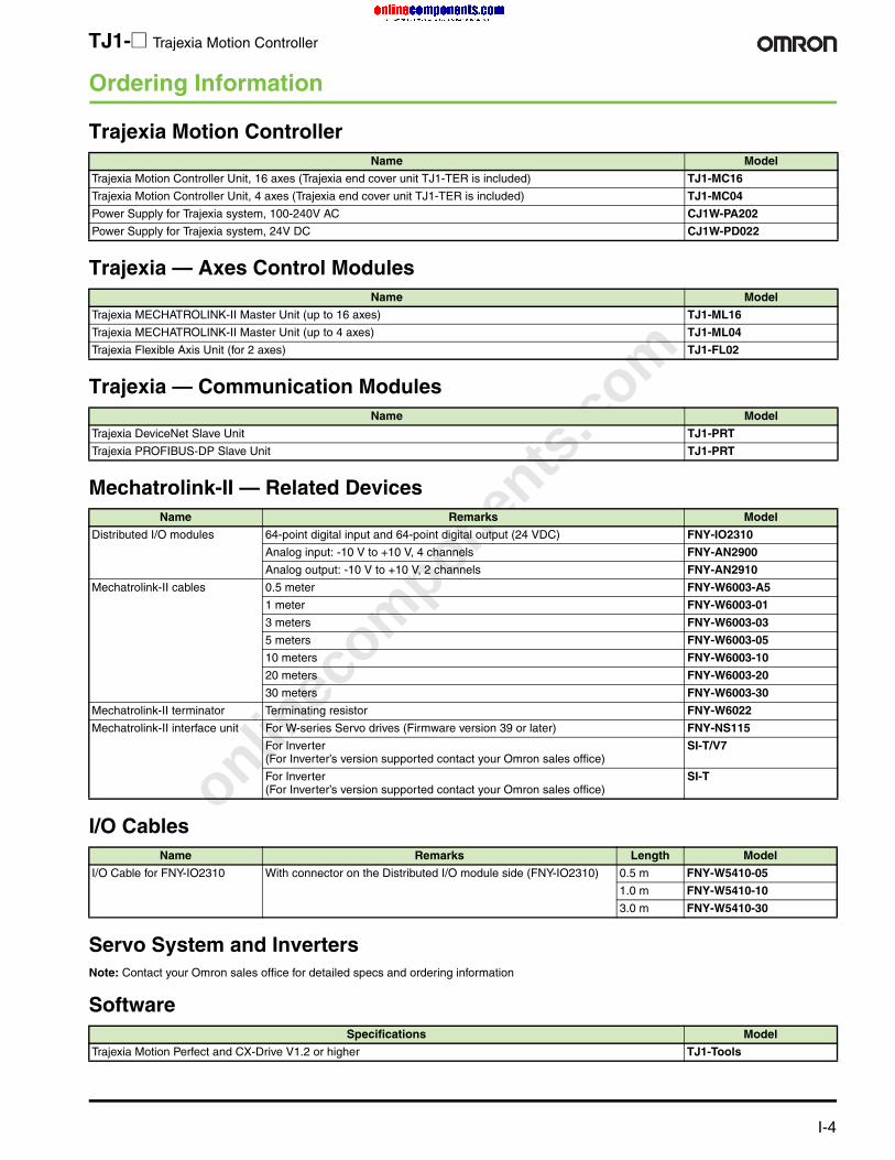
Ordering Information
Trajexia Motion Controller
Trajexia — Axes Control Modules
Trajexia — Communication Modules
Mechatrolink-II — Related Devices
I/O Cables
Servo System and InvertersNote: Contact your Omron sales office for detailed specs and ordering information
Software
Name Model
Trajexia Motion Controller Unit, 16 axes (Trajexia end cover unit TJ1-TER is included) TJ1-MC16
Trajexia Motion Controller Unit, 4 axes (Trajexia end cover unit TJ1-TER is included) TJ1-MC04
Power Supply for Trajexia system, 100-240V AC CJ1W-PA202
Power Supply for Trajexia system, 24V DC CJ1W-PD022
Name Model
Trajexia MECHATROLINK-II Master Unit (up to 16 axes) TJ1-ML16
Trajexia MECHATROLINK-II Master Unit (up to 4 axes) TJ1-ML04
Trajexia Flexible Axis Unit (for 2 axes) TJ1-FL02
Name Model
Trajexia DeviceNet Slave Unit TJ1-PRT
Trajexia PROFIBUS-DP Slave Unit TJ1-PRT
Name Remarks Model
Distributed I/O modules 64-point digital input and 64-point digital output (24 VDC) FNY-IO2310
Analog input: -10 V to +10 V, 4 channels FNY-AN2900
Analog output: -10 V to +10 V, 2 channels FNY-AN2910
Mechatrolink-II cables 0.5 meter FNY-W6003-A5
1 meter FNY-W6003-01
3 meters FNY-W6003-03
5 meters FNY-W6003-05
10 meters FNY-W6003-10
20 meters FNY-W6003-20
30 meters FNY-W6003-30
Mechatrolink-II terminator Terminating resistor FNY-W6022
Mechatrolink-II interface unit For W-series Servo drives (Firmware version 39 or later) FNY-NS115
For Inverter(For Inverter’s version supported contact your Omron sales office)
SI-T/V7
For Inverter(For Inverter’s version supported contact your Omron sales office)
SI-T
Name Remarks Length Model
I/O Cable for FNY-IO2310 With connector on the Distributed I/O module side (FNY-IO2310) 0.5 m FNY-W5410-05
1.0 m FNY-W5410-10
3.0 m FNY-W5410-30
Specifications Model
Trajexia Motion Perfect and CX-Drive V1.2 or higher TJ1-Tools

onlinec
omponen
ts.co
m
For complete specifications and additional models: U.S. www.omron.com/oei Canada www.omron.ca I-5
W-Series Servos
High-Precision Positioning with Advanced CommunicationsOmron's compact W-Series servos were designed with zero compromise on quality reliability or performance. The servo amplifiers are ultra-compact with pulse and analog inputs as standard, plus an auto-tuning function. Plug-in option cards offer enhanced functionality such as indexing and complex motions such as cams, gears and linked axes. MECHATROLINK-II high-speed bus provides instant communications between Omron’s W-Series servo drives and PLC-based motion controllers and simplifies coordination of up to 30 axes.
Servo Driver Features• 300% peak current for 3 seconds• Automatic motor recognition with auto-tuning function• Analog and pulse inputs for speed, torque and position
control• MECHATROLINK-II communications bus available built-in
(WN-drives) or as an option unit (WT-drives)• Field bus option units include DeviceNet and Profibus• Special function option units available for motion controller
and indexer• Trace function allows oscilloscope function for monitoring
Servo Motor Features• 6 different designs provide a complete range of servo motors
to meet the power, speed and performance required for each application
• Peak torque 300% of nominal during 3 seconds• Slim profile and standard cylindrical motor types• High resolution incremental encoders standard, absolute
encoders available• Built-in 24V brake available• Shaft options include straight, with keyway, and with keyway
and tap• IP67 and shaft oil seal available
MECHATROLINK-II is a registered trademark of Yaskawa Corporation.
Servos
W-Series L100

onlinec
omponen
ts.co
m
I-6 For complete specifications and additional models: U.S. www.omron.com/oei Canada www.omron.ca
W-Series Servos
Servo Motor and Servo Drive CombinationsServo motors with absolute encoders are available but not shown below.
Note: *A regenerative resistor (model R88A-RR8806) must be ordered with these servo drivers.
Servo Motor (R88M-W@@@@@@-@@@) Servo drive model with MECHATROLINK-II communications
(R88D-WN@@@-ML2)
Servo drive model (R88D-WT@@@@)
Description Capacity Model(-W@@@@@@)
Brake and Shaft end options (-@@@)
100 V 200 V, 1-phase
200 V, 3-phase
100 V 200 V, 1-phase
200 V, 2-phase
Cylindrical3000 rpm, incremental encoder, IP55 (excluding shaft opening)
30 W 03030H Without brake (blank)With brake (-B)Straight shaft (blank)Shaft with key (-S1)Shaft with key and tap (-S2)
— — — A3HL A3H —
50 W 05030H A5L A5H — A5HL A5H —
100 W 10030H 01L 01H — 01HL 01H —
200 W 20030H 02L 02H — 02HL 02H —
400 W 40030H 04L 04H — — 04H —
750 W 75030H — 08H — — 08H 08H
Cylindrical3000 rpm, incremental encoder, IP67 (excluding shaft opening)
1 KW 1K030H Without brake (blank)With brake (-B)Straight shaft (blank)Shaft with key and tap (-S2)
— — 10H — — 10H
1.5 KW 1K530H — — 15H — — 15H
2 KW 2K030H — — 20H — — 20H
3 KW 3K030H — — 30H — — 30H
4 KW 4K030H — — — — — 50H
5 KW 5K030H — — — — — 50H
Cylindrical 1500 rpm,incremental encoder, IP67 (excluding shaft opening)
450 W 45015H Without brake (blank)With brake (-B)Straight shaft (blank)Shaft with key and tap (-S2)
— — 05H — — 05H
850 W 85015H — — 10H — — 10H
1.3 KW 1K315H — — 15H — — 15H
1.8 KW 1K815H — — 20H — — 20H
2.9 KW 2K915H — — — — — 30H
4.4 KW 4K415H — — — — — 50H
5.5 KW 5K515H — — — — — 60H*
7.5 KW 7K515H — — — — — 75H*
11 KW 11K015H — — — — — 150H*
15 KW 15K015H — — — — — 150H*
Cylindrical 1000 rpm, incremental encoder, IP67 (excluding shaft opening)
300 W 30010H Without brake (blank)With brake (-B)Straight shaft (blank)Shaft with key and tap (-S2)
— — 05H — — 05H
600 W 60010H — — 10H — — 08H
900 W 90010H — — 10H — — 10H
1.2 KW 1K210H — — 15H — — 15H
2 KW 2K010H — — 20H — — 20H
3 KW 3K010H — — — — — 30H
4 KW 4K010H — — — — — 50H
5 KW 5K010H — — — — — 60H*
Flat style, 3000 rpm, incremental encoder, IP55 (excluding shaft opening) or IP67 (including shaft opening)
100 W P10030H Without brake (blank)With brake (-B)Straight shaft (blank)Shaft with key (-S1)Shaft with key and tap (-S2)
01L 01H — 01HL 01H —
200 W P20030H 02L 02H — 02HL 02H —
400 W P40030H 04L 04H — — 04H —
750 W P75030H — 08H — — 08H 08H
1.5 KW P1K530H — — 15H — — 15H

onlinec
omponen
ts.co
m
For complete specifications and additional models: U.S. www.omron.com/oei Canada www.omron.ca I-7
W-Series Servos
Ordering Information
Servo Drives (R88D)Watts Voltage Phase Model
Standard With MECHATROLINK-II
30 100 1 R88D-WTA3HL —
50 100 1 R88D-WTA5HL R88D-WNA5L-ML2
100 100 1 R88D-WT01HL R88D-WN01L-ML2
200 100 1 R88D-WT02HL R88D-WN02L-ML2
400 100 1 — R88D-WN04L-ML2
30 200 1 R88D-WTA3H —
50 200 1 R88D-WTA5H R88D-WNA5H-ML2
100 200 1 R88D-WT01H R88D-WN01H-ML2
200 200 1 R88D-WT02H R88D-WN02H-ML2
400 200 1 R88D-WT04H R88D-WN04H-ML2
750 200 1 — R88D-WN08H-ML2
500 200 3 R88D-WT05H R88D-WN05H-ML2
750 200 3 R88D-WT08H —
1000 200 3 R88D-WT10H R88D-WN10H-ML2
1500 200 3 R88D-WT15H R88D-WN15H-ML2
2000 200 3 R88D-WT20H R88D-WN20H-ML2
3000 200 3 R88D-WT30H R88D-WN30H-ML2
4000 200 3 R88D-WT50H —
5000 200 3 R88D-WT50H —
5500 200 3 R88D-WT60H —
7500 200 3 R88D-WT75H —
15,000 200 3 R88D-WT150H —
W-SeriesServo Drive
Battery for AbsoluteEncoder
Analog Monitor
Parameter Unit Computer with WindowsMonitoring Software
Motion ControlModule
NC InterfaceTerminal Block
Position ControlModule
Universal Terminal Block
W-Series Servo Motor
1
2
3
45
67
8 8
9
10
11
12

onlinec
omponen
ts.co
m
I-8 For complete specifications and additional models: U.S. www.omron.com/oei Canada www.omron.ca
W-Series Servos
Cylindrical Style Servo Motors
Build a part number as follows:R88M-W75030T-BS2 = 750 W, 3000 RPM, 200 VAC motor with absolute encoder, brakes, and shaft with key and tap
Flat Style Servo Motors
Build a part number as follows:R88M-WP20030H-BWS1 = 200 W, 3000 RPM, 200 VAC motor with absolute encoder, brakes, waterproof seal (IP67), and shaft with key
R88M-W@@@ @@ @- @ @ @@4 5 6 7 8 9
4 5 Basic model 6 7 8 9
Capacity Rotation speed
Cylindrical style Motor power supply and encoder typeH = 200 VAC, incrementalL = 100 VAC, incrementalT = 200 VAC, absoluteS = 100 VAC absolute
With/without brakes
Oil seal optionsBlank = noneO = oil seal
Shaft shapeBlank: straightS1 = with keyS2 = with key and tapS3 = straight with tap
W RPM R88M-W H L T S Blank B Blank O W Blank S1 S2 S3
30 3,000 R88M-W03030 Yes Yes Yes Yes Yes Yes Yes Yes — Yes Yes Yes Yes
50 R88M-W05030 Yes Yes Yes Yes Yes Yes Yes Yes — Yes Yes Yes Yes
100 R88M-W10030 Yes Yes Yes Yes Yes Yes Yes Yes — Yes Yes Yes Yes
200 R88M-W20030 Yes Yes Yes Yes Yes Yes Yes Yes — Yes Yes Yes Yes
400 R88M-W40030 Yes — Yes — Yes Yes Yes Yes — Yes Yes Yes Yes
750 R88M-W75030 Yes — Yes — Yes Yes Yes Yes — Yes Yes Yes Yes
1 kW R88M-W1K030 Yes — Yes — Yes Yes Yes Yes — Yes — Yes —
1.5 kW R88M-W1K530 Yes — Yes — Yes Yes Yes Yes — Yes — Yes —
2 kW R88M-W2K030 Yes — Yes — Yes Yes Yes Yes — Yes — Yes —
3 kW R88M-W3K030 Yes — Yes — Yes Yes Yes Yes — Yes — Yes —
4 kW R88M-W4K030 Yes — Yes — Yes Yes Yes Yes — Yes — Yes —
5 kW R88M-W5K030 Yes — Yes — Yes Yes Yes Yes — Yes — Yes —
450 1,500 R88M-W45015 — — Yes — Yes Yes Yes Yes — Yes — Yes —
850 R88M-W85015 — — Yes — Yes Yes Yes Yes — Yes — Yes —
1.3 kW R88M-W1K315 — — Yes — Yes Yes Yes Yes — Yes — Yes —
1.8 kW R88M-W1K815 — — Yes — Yes Yes Yes Yes — Yes — Yes —
2.9 kW R88M-W2K915 — — Yes — Yes Yes Yes Yes — Yes — Yes —
4.4 kW R88M-W4K415 — — Yes — Yes Yes Yes Yes — Yes — Yes —
5.5 kW R88M-W5K515 — — Yes — Yes Yes Yes Yes — Yes — Yes —
7.5 kW R88M-W7K515 — — Yes — Yes Yes Yes Yes — Yes — Yes —
11 kW R88M-W11K015 — — Yes — Yes Yes Yes Yes — Yes — Yes —
15 kW R88M-W15K015 — — Yes — Yes Yes Yes Yes — Yes — Yes —
300 1,000 R88M-W30010 Yes — Yes — Yes Yes Yes Yes — Yes — Yes —
600 R88M-W60010 Yes — Yes — Yes Yes Yes Yes — Yes — Yes —
900 R88M-W90010 Yes — Yes — Yes Yes Yes Yes — Yes — Yes —
1.2 kW R88M-W1K210 Yes — Yes — Yes Yes Yes Yes — Yes — Yes —
2 kW R88M-W2K010 Yes — Yes — Yes Yes Yes Yes — Yes — Yes —
3 kW R88M-W3K010 Yes — Yes — Yes Yes Yes Yes — Yes — Yes —
4 kW R88M-W4K010 Yes — Yes — Yes Yes Yes Yes — Yes — Yes —
5.5 kW R88M-W5K510 Yes — Yes — Yes Yes Yes Yes — Yes — Yes —
R88M-WP@@@ @@ @- @ @ @@4 5 6 7 8 9
4 5 Basic model 6 7 8 9
Capacity Rota-tion speed
Flat style Motor power supply and encoder typeH = 200 VAC, incrementalL = 100 VAC, incrementalT = 200 VAC, absoluteS = 100 VAC absolute
With/without brakes
Waterproof (IP67) /oil seal optionsBlank = noneO = oil sealW = waterproof
Shaft shapeBlank: straightS1 = with keyS2 = with key and tapS3 = straight with tap
W RPM R88M-WP H L T S Blank B Blank O W Blank S1 S2 S3
100 W 3,000 R88M-WP10030 Yes Yes Yes Yes Yes Yes Yes Yes Yes Yes Yes Yes Yes
200 W R88M-WP20030 Yes Yes Yes Yes Yes Yes Yes Yes Yes Yes Yes Yes Yes
400 W R88M-WP40030 Yes — Yes — Yes Yes Yes Yes Yes Yes Yes Yes Yes
750 W R88M-WP75030 Yes — Yes — Yes Yes Yes Yes Yes Yes Yes Yes Yes
1.5 kW R88M-WP1K530 Yes — Yes — Yes Yes Yes Yes Yes Yes Yes Yes Yes
onlinec
omponen
ts.co
m
For complete specifications and additional models: U.S. www.omron.com/oei Canada www.omron.ca I-9
W-Series Servos
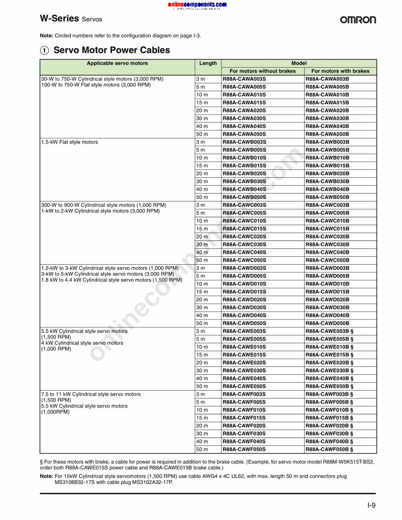
Note: Circled numbers refer to the configuration diagram on page I-3.
A Servo Motor Power Cables
§ For these motors with brake, a cable for power is required in addition to the brake cable. (Example, for servo motor model R88M-W5K515T-BS2, order both R88A-CAWE015S power cable and R88A-CAWE015B brake cable.)
Note: For 15kW Cylindrical style servomotors (1,500 RPM) use cable AWG4 x 4C UL62, with max. length 50 m and connectors plug MS3108B32-17S with cable plug MS3102A32-17P.
Applicable servo motors Length Model
For motors without brakes For motors with brakes
30-W to 750-W Cylindrical style motors (3,000 RPM) 100-W to 750-W Flat style motors (3,000 RPM)
3 m R88A-CAWA003S R88A-CAWA003B
5 m R88A-CAWA005S R88A-CAWA005B
10 m R88A-CAWA010S R88A-CAWA010B
15 m R88A-CAWA015S R88A-CAWA015B
20 m R88A-CAWA020S R88A-CAWA020B
30 m R88A-CAWA030S R88A-CAWA030B
40 m R88A-CAWA040S R88A-CAWA040B
50 m R88A-CAWA050S R88A-CAWA050B
1.5-kW Flat style motors 3 m R88A-CAWB003S R88A-CAWB003B
5 m R88A-CAWB005S R88A-CAWB005B
10 m R88A-CAWB010S R88A-CAWB010B
15 m R88A-CAWB015S R88A-CAWB015B
20 m R88A-CAWB020S R88A-CAWB020B
30 m R88A-CAWB030S R88A-CAWB030B
40 m R88A-CAWB040S R88A-CAWB040B
50 m R88A-CAWB050S R88A-CAWB050B
300-W to 900-W Cylindrical style motors (1,000 RPM) 1-kW to 2-kW Cylindrical style motors (3,000 RPM)
3 m R88A-CAWC003S R88A-CAWC003B
5 m R88A-CAWC005S R88A-CAWC005B
10 m R88A-CAWC010S R88A-CAWC010B
15 m R88A-CAWC015S R88A-CAWC015B
20 m R88A-CAWC020S R88A-CAWC020B
30 m R88A-CAWC030S R88A-CAWC030B
40 m R88A-CAWC040S R88A-CAWC040B
50 m R88A-CAWC050S R88A-CAWC050B
1.2-kW to 3-kW Cylindrical style servo motors (1,000 RPM) 3-kW to 5-kW Cylindrical style servo motors (3,000 RPM)1.8 kW to 4.4 kW Cylindrical style servo motors (1,500 RPM)
3 m R88A-CAWD003S R88A-CAWD003B
5 m R88A-CAWD005S R88A-CAWD005B
10 m R88A-CAWD010S R88A-CAWD010B
15 m R88A-CAWD015S R88A-CAWD015B
20 m R88A-CAWD020S R88A-CAWD020B
30 m R88A-CAWD030S R88A-CAWD030B
40 m R88A-CAWD040S R88A-CAWD040B
50 m R88A-CAWD050S R88A-CAWD050B
5.5 kW Cylindrical style servo motors(1,500 RPM)4 kW Cylindrical style servo motors(1,000 RPM)
3 m R88A-CAWE003S R88A-CAWE003B §
5 m R88A-CAWE005S R88A-CAWE005B §
10 m R88A-CAWE010S R88A-CAWE010B §
15 m R88A-CAWE015S R88A-CAWE015B §
20 m R88A-CAWE020S R88A-CAWE020B §
30 m R88A-CAWE030S R88A-CAWE030B §
40 m R88A-CAWE040S R88A-CAWE040B §
50 m R88A-CAWE050S R88A-CAWE050B §
7.5 to 11 kW Cylindrical style servo motors(1,500 RPM)5.5 kW Cylindrical style servo motors(1,000RPM)
3 m R88A-CAWF003S R88A-CAWF003B §
5 m R88A-CAWF005S R88A-CAWF005B §
10 m R88A-CAWF010S R88A-CAWF010B §
15 m R88A-CAWF015S R88A-CAWF015B §
20 m R88A-CAWF020S R88A-CAWF020B §
30 m R88A-CAWF030S R88A-CAWF030B §
40 m R88A-CAWF040S R88A-CAWF040B §
50 m R88A-CAWF050S R88A-CAWF050B §
onlinec
omponen
ts.co
m
I-10 For complete specifications and additional models: U.S. www.omron.com/oei Canada www.omron.ca
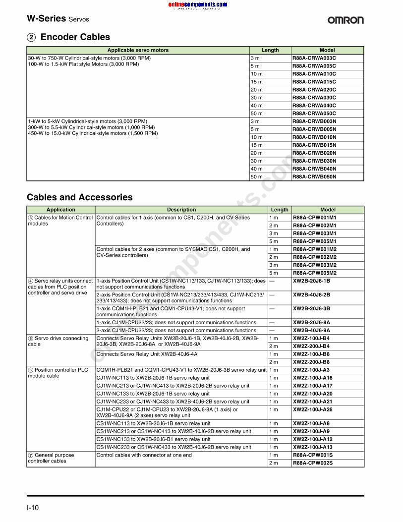
W-Series Servos
B Encoder CablesApplicable servo motors Length Model
30-W to 750-W Cylindrical-style motors (3,000 RPM) 100-W to 1.5-kW Flat style Motors (3,000 RPM)
3 m R88A-CRWA003C
5 m R88A-CRWA005C
10 m R88A-CRWA010C
15 m R88A-CRWA015C
20 m R88A-CRWA020C
30 m R88A-CRWA030C
40 m R88A-CRWA040C
50 m R88A-CRWA050C
1-kW to 5-kW Cylindrical-style motors (3,000 RPM) 300-W to 5.5-kW Cylindrical-style motors (1,000 RPM)450-W to 15.0-kW Cylindrical-style motors (1,500 RPM)
3 m R88A-CRWB003N
5 m R88A-CRWB005N
10 m R88A-CRWB010N
15 m R88A-CRWB015N
20 m R88A-CRWB020N
30 m R88A-CRWB030N
40 m R88A-CRWB040N
50 m R88A-CRWB050N
Cables and AccessoriesApplication Description Length Model
C Cables for Motion Control modules
Control cables for 1 axis (common to CS1, C200H, and CV-Series Controllers)
1 m R88A-CPW001M1
2 m R88A-CPW002M1
3 m R88A-CPW003M1
5 m R88A-CPW005M1
Control cables for 2 axes (common to SYSMAC CS1, C200H, and CV-Series controllers)
1 m R88A-CPW001M2
2 m R88A-CPW002M2
3 m R88A-CPW003M2
5 m R88A-CPW005M2
D Servo relay units connect cables from PLC position controller and servo drive
1-axis Position Control Unit (CS1W-NC113/133, CJ1W-NC113/133); does not support communications functions
— XW2B-20J6-1B
2-axis Position Control Unit (CS1W-NC213/233/413/433, CJ1W-NC213/233/413/433); does not support communications functions
— XW2B-40J6-2B
1-axis CQM1H-PLB21 and CQM1-CPU43-V1; does not support communications functions
— XW2B-20J6-3B
1-axis CJ1M-CPU22/23; does not support communications functions — XW2B-20J6-8A
2-axis CJ1M-CPU22/23; does not support communications functions — XW2B-40J6-9A
E Servo drive connecting cable
Connects Servo Relay Units XW2B-20J6-1B, XW2B-40J6-2B, XW2B-20J6-3B, XW2B-20J6-8A, or XW2B-40J6-9A
1 m XW2Z-100J-B4
2 m XW2Z-200J-B4
Connects Servo Relay Unit XW2B-40J6-4A 1 m XW2Z-100J-B8
2 m XW2Z-200J-B8
F Position controller PLC module cable
CQM1H-PLB21 and CQM1-CPU43-V1 to XW2B-20J6-3B servo relay unit 1 m XW2Z-100J-A3
CJ1W-NC113 to XW2B-20J6-1B servo relay unit 1 m XW2Z-100J-A16
CJ1W-NC213 or CJ1W-NC413 to XW2B-20J6-2B servo relay unit 1 m XW2Z-100J-A17
CJ1W-NC133 to XW2B-20J6-1B servo relay unit 1 m XW2Z-100J-A20
CJ1W-NC233 or CJ1W-NC433 to XW2B-40J6-2B servo relay unit 1 m XW2Z-100J-A21
CJ1M-CPU22 or CJ1M-CPU23 to XW2B-20J6-8A (1 axis) or XW2B-40J6-9A (2 axes) servo relay unit
1 m XW2Z-100J-A26
CS1W-NC113 to XW2B-20J6-1B servo relay unit 1 m XW2Z-100J-A8
CS1W-NC213 or CS1W-NC413 to XW2B-40J6-2B servo relay unit 1 m XW2Z-100J-A9
CS1W-NC133 to XW2B-20J6-B1 servo relay unit 1 m XW2Z-100J-A12
CS1W-NC233 or CS1W-NC433 to XW2B-40J6-2B servo relay unit 1 m XW2Z-100J-A13
G General purpose controller cables
Control cables with connector at one end 1 m R88A-CPW001S
2 m R88A-CPW002S

onlinec
omponen
ts.co
m
For complete specifications and additional models: U.S. www.omron.com/oei Canada www.omronca I-11
W-Series Servos
External Regenerative Resistors
* Resistor required for use with Servo Driver models R88D-WT60H/WT75H/WT150H.
DC Reactors
AC Reactors
Network Communication AdaptersDeviceNet Option Unit mounts to a W-Series AC Servo drives andperforms both DeviceNet communications functions and PositionControl Unit functions. Parameters can be set, the operating statuscan be monitored, and faults can be predicted from a PLC up to 500m away.
• Trace Function: When trigger conditions are satisfied, up to twoanalog elements and two ON/OFF elements can be recorded in theDeviceNet Option Unit and read from the PLC.
• Monitor Item Reading Function: The contents of AC Servo drivemonitor display can be read from the PLC.
• Batch Handling of Operating Information for Servo SystemsInformation that can be displayed at W-series AC Servo Driversusing monitor functions (e.g., speed commands and speed feed-back) can be read by a PLC using remote I/O functions.
MECHATROLINK-II Interface Unit for WT-Series Drives
H Universal terminal block cable
Cables for universal terminal block XW2B-50G5 1 m R88A-CTW001N
2 m R88A-CTW002N
Control I/O connector; fits port CN1 (WT-series only) — R88A-CNU11C
Control I/O connector; fits port CN1 (WN-series only) — R88A-CNW01C
Universal terminal block — XW2B-50G5
Cable from relay terminal block XW2B-20G4/XW2B-20G5/XW2D-20G6 to WN-series servo drive CN1
1 m XW2Z-100J-B16
2 m XW2Z-200J-B16
Cable from relay terminal block XW2B-20G4/XW2B-20G5/XW2D-20G6 to WT-series servo drive CN1
1 m XW2Z-100J-B15
2 m XW2Z-200J-B15
I Battery backup Servo drives R88D-WT50H or less — R88A-BAT01W
Servo drives R88D-WT60H/75H/150H — R88A-BAT02W
Servo drives R88D-WN, all models (connected in series with encoder cables in B)
0.3 m R88A-CRWC0R3C
J Analog monitor cable Peripheral cable for analog monitoring; servo drive to PC; connects to port CN4
1 m R88A-CMW001S
K Parameter unit Panel mount unit sets and displays servo drive parameters; includes cable 1 m R88A-PR02W
L Personal computer cable Connects a personal computer for monitoring; servo drive to PC; connects to port CN3
2 m R88A-CCW002P2
Cables and Accessories (Continued)
Application Description Length Model
Rating Model
220 W 47 Ω R88A-RR22047S
880 W 6.25 Ω R88A-RR88006*
Applicable servo drive Model
For R88D-WT30H R88A-PX5059
For R88D-WT15H/WT20H R88A-PX5060
For R88D-WT05H/WT08H/WT10H R88A-PX5061
For R88D-WT02HL R88A-PX5062
For R88D-WTA3HL/WTA5HL/WT01HL R88A-PX5063
For R88D-WT50H R88A-PX5068
For R88D-WT04H R88A-PX5069
For R88D-WT02H R88A-PX5070
For R88D-WTA3H/WTA5H/WT01H R88A-PX5071
Applicable servo drive Model
For R88D-WTA3HL to WT01HL/-WD30H to WD02H
R88A-F1W104-E
For R88D-WT02HL/WT04H R88A-F1W107-E
For R88D-WT05H/WT08H R88A-F1W115-E
For R88D-WT10H R88A-F1W125-E
For R88D-WT15H/WT20H LF-315K
For R88D-WT30H LF-325K
For R88D-WT50H LF-335K
For R88D-WT60H LF-380K
Description Model
DeviceNet Option Unit R88A-NCW152-DRT
External I/O Connector R88A-CNU01R
Cable for Setup Tool (IBM PC/AT or compatible; 2 m length
R88A-CCW002P4
Description Cable length
Model
MECHATROLINK-II Interface Unit — FNY-NS115
MECHATROLINK-II cable 0.5 m FNY-W6003-A5
1 m FNY-W6003-01
3 m FNY-W6003-03
5 m FNY-W6003-05
10 m FNY-W6003-10
20 m FNY-W6003-20
30 m FNY-W6003-30
MECHATROLINK-II terminating resistor
— FNY-W6022
onlinec
omponen
ts.co
m
I-12 For complete specifications and additional models: U.S. www.omron.com/oei Canada www.omron.ca
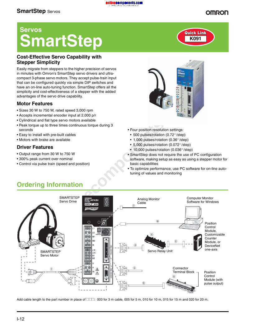
SmartStep Servos
Cost-Effective Servo Capability with Stepper SimplicityEasily migrate from steppers to the higher precision of servos in minutes with Omron's SmartStep servo drivers and ultra-compact 3-phase servo motors. They accept pulse-train input that can be configured quickly via simple DIP switches and have an on-line auto-tuning function. SmartStep offers all the simplicity and cost-effectiveness of a stepper with the added advantages of the servo drive capability.
Motor Features• Sizes 30 W to 750 W, rated speed 3,000 rpm• Accepts incremental encoder input at 2,000 p/r• Cylindrical and flat type servo motors available• Peak torque up to three times continuous torque during 3
seconds• Easy to install with pre-built cables• Motors with brake are available
Driver Features• Output range from 30 W to 750 W• 300% peak current over nominal• Control via pulse train (speed and position)
• Four position resolution settings: • 500 pulses/rotation (0.72° /step)• 1,000 pulses/rotation (0.36° /step)• 5,000 pulses/rotation (0.072° /step)• 10,000 pulses/rotation (0.036° /step)
• SmartStep does not require the use of PC configuration software, making setup as easy as using a stepper motor for basic capabilities
• To optimize performance, use PC software for on-line auto-tuning of values and monitoring
Ordering Information
Add cable length to the part number in place of @@@: 003 for 3 m cable, 005 for 5 m, 010 for 10 m, 015 for 15 m and 020 for 20 m.
Servos
SmartStep K091
SMARTSTEPServo Drive
SMARTSTEPServo Motor
Computer Monitor Software for Windows
Servo Relay Unit
Connector Terminal Block Position
Control Module (with pulse output)
Position Control Module, Customizable Counter Module, or DeviceNet one-axis
Analog Monitor Cable

onlinec
omponen
ts.co
m
For complete specifications and additional models: U.S. www.omron.com/oei Canada www.omron.ca I-13
SmartStep Servos
Note: Circled numbers refer to the configuration diagram on page I-8.
SmartStep ServosWattage Servo motor model Servo drive model APower cable/Encoder cable model
(Add cable length for @@@)Cylindrical Servo Motors 100 VAC Without Brake, Shaft Without Keyway30 W R7M-A03030-S1 R7D-APA3L R7A-CEA@@@S50 W R7M-A05030-S1 R7D-APA5L R7A-CEA@@@S100 W R7M-A10030-S1 R7D-AP01L R7A-CEA@@@S200 W R7M-A20030-S1 R7D-AP02L R7A-CEA@@@S400 W R7M-A40030-S1 R7D-AP04L R7A-CEA@@@SCylindrical Servo Motors 100 VAC With Brake, Shaft With Keyway30 W R7M-A03030-BS1 R7D-APA3L R7A-CEA@@@B50 W R7M-A05030-BS1 R7D-APA5L R7A-CEA@@@B100 W R7M-A10030-BS1 R7D-AP01L R7A-CEA@@@B200 W R7M-A20030-BS1 R7D-AP02L R7A-CEA@@@B400 W R7M-A40030-BS1 R7D-AP04L R7A-CEA@@@BCylindrical Servo Motors 200 VAC Without Brake, Shaft With Keyway30 W R7M-A03030-S1 R7D-APA3H R7A-CEA@@@S50 W R7M-A05030-S1 R7D-APA5H R7A-CEA@@@S100 W R7M-A10030-S1 R7D-AP01H R7A-CEA@@@S200 W R7M-A20030-S1 R7D-AP02H R7A-CEA@@@S400 W R7M-A40030-S1 R7D-AP04H R7A-CEA@@@S750 W R7M-A75030-S1 R7D-AP08H R7A-CEA@@@SCylindrical Servo Motors 200 VAC With Brake, Shaft With Keyway30 W R7M-A03030-BS1 R7D-APA3H R7A-CEA@@@B50 W R7M-A05030-BS1 R7D-APA5H R7A-CEA@@@B100 W R7M-A10030-BS1 R7D-AP01H R7A-CEA@@@B200 W R7M-A20030-BS1 R7D-AP02H R7A-CEA@@@B400 W R7M-A40030-BS1 R7D-AP04H R7A-CEA@@@B750 W R7M-A75030-BS1 R7D-AP08H R7A-CEA@@@BFlat Servo Motors 100 VAC Without Brake, Shaft With Keyway100 W R7M-AP10030-S1 R7D-AP01L R7A-CEA@@@S200 W R7M-AP20030-S1 R7D-AP02L R7A-CEA@@@S400 W R7M-AP40030-S1 R7D-AP04L R7A-CEA@@@SFlat Servo Motors 100 VAC With Brake, Shaft With Keyway100 W R7M-AP10030-BS1 R7D-AP01L R7A-CEA@@@B 200 W R7M-AP20030-BS1 R7D-AP02L R7A-CEA@@@B400 W R7M-AP40030-BS1 R7D-AP04L R7A-CEA@@@BFlat Servo Motors 200 VAC Without Brake, Shaft With Keyway100 W R7M-AP10030-S1 R7D-AP01H R7A-CEA@@@S200 W R7M-AP20030-S1 R7D-AP02H R7A-CEA@@@S400 W R7M-AP40030-S1 R7D-AP04H R7A-CEA@@@S750 W R7M-AP75030-S1 R7D-AP08H R7A-CEA@@@SFlat Servo Motors 200 VAC With Brake, Shaft With Keyway100 W R7M-AP10030-BS1 R7D-AP01H R7A-CEA@@@B200 W R7M-AP20030-BS1 R7D-AP02H R7A-CEA@@@B400 W R7M-AP40030-BS1 R7D-AP04H R7A-CEA@@@B750 W R7M-AP75030-BS1 R7D-AP08H R7A-CEA@@@B
onlinec
omponen
ts.co
m
I-14 For complete specifications and additional models: U.S. www.omron.com/oei Canada www.omron.ca
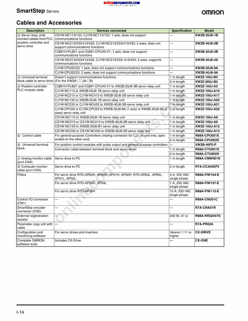
SmartStep Servos
Cables and AccessoriesDescription Devices connected Specification Model
B Servo relay units connect cables from PLC position controller and servo drive
CS1W-NC113/133, CJ1W-NC113/133; 1 axis; does not support communications functions
— XW2B-20J6-1B
CS1W-NC213/233/413/433, CJ1W-NC213/233/413/433; 2 axes; does not support communications functions
— XW2B-40J6-2B
CQM1H-PLB21 and CQM1-CPU43-V1; 1 axis; does not support communications functions
— XW2B-20J6-3B
CS1W-NC213/233/413/433, CJ1W-NC213/233/ 413/433; 2 axes; supports communications functions
— XW2B-40J6-4A
CJ1M-CPU22/23; 1 axis; does not support communications functions — XW2B-20J6-8ACJ1M-CPU22/23; 2 axes; does not support communications functions — XW2B-40J6-9A
C Universal terminal block cable to servo drive
Doesn’t support communications functions.(For the XW2B-@@J6-@B)
1 m length XW2Z-100J-B52 m length XW2Z-200J-B5
D Position controller PLC module cable
CQM1H-PLB21 and CQM1-CPU43-V1 to XW2B-20J6-3B servo relay unit 1 m length XW2Z-100J-A3CJ1W-NC113 to XW2B-20J6-1B servo relay unit 1 m length XW2Z-100J-A16CJ1W-NC213 or CJ1W-NC413 to XW2B-20J6-2B servo relay unit 1 m length XW2Z-100J-A17CJ1W-NC133 to XW2B-20J6-1B servo relay unit 1 m length XW2Z-100J-A20CJ1W-NC233 or CJ1W-NC433 to XW2B-40J6-2B servo relay unit 1 m length XW2Z-100J-A21CJ1M-CPU22 or CJ1M-CPU23 to XW2B-20J6-8A (1 axis) or XW2B-40J6-9A (2 axes) servo relay unit
1 m length XW2Z-100J-A26
CS1W-NC113 to XW2B-20J6-1B servo relay unit 1 m length XW2Z-100J-A8CS1W-NC213 or CS1W-NC413 to XW2B-40J6-2B servo relay unit 1 m length XW2Z-100J-A9CS1W-NC133 to XW2B-20J6-B1 servo relay unit 1 m length XW2Z-100J-A12CS1W-NC233 or CS1W-NC433 to XW2B-40J6-2B servo relay unit 1 m length XW2Z-100J-A13
E Control cable For general-purpose Controllers (mating connector for CJ1 on one end, open ended on the other end)
1 m length R88A-CPU001S2 m length R88A-CPU002S
F Universal terminal block
For position control modules with pulse output and general-purpose controllers — XW2B-40F5-PConnector cable between terminal block and servo driver 1 m length R88A-CTU001N
2 m length R88A-CTU002NG Analog monitor cable (port CN4)
Servo drive to PC 1 m length R88A-CMW001S
H Computer monitor cable (port CN3)
Servo drive to PC 2 m length R7A-CCA002P2
Filters For servo drive R7D-APA3H, APA5H, AP01H, AP02H; R7D-APA3L, APA5L, AP01L, AP02L
4 A, 250 VAC single phase
R88A-FIW104-E
For servo drive R7D-AP04H, AP04L 7 A, 250 VAC single phase
R88A-FIW107-E
For servo drive R7D-AP08H 15 A, 250 VAC single phase
R88A-FIW115-E
Control I/O connector (CN1)
— — R88A-CNU01C
SmartStep encoder connector (CN2)
— — R7A-CNA01R
External regeneration resistor
— 200 W, 47 Ω R88A-RR22047S
Parameter copy unit with cable
— — R7A-PR02A
Configuration and monitoring software
For servo drives and inverters Version 1.11 or higher
CX-DRIVE
Complete OMRON software suite
Includes CX-Drive — CX-ONE

onlinec
omponen
ts.co
m
For complete specifications and additional models: U.S. www.omron.com/oei Canada www.omron.ca I-15
SmartStep Servos
Specifications
Servo Drives General Specifications
Servo Drives Performance Specifications100 VAC Input Models
200 VAC Input Models
Item Specification
Operating ambient 0° to 55° C (32° F to 131° F), 90% RH max. (with no condensation)
Storage ambient -20° to 85° C (-4° F to 185° F), 90% RH max. (with no condensation)
Storage/operating atmosphere No corrosive gases.
Vibration resistance 10 to 55 Hz in X, Y, and Z directions with 0.1-mm double amplitude or acceleration of 4.9 m/s2 max., whichever is smaller
Impact resistance Acceleration 19.6 m/s2 max., in X, Y, and Z directions, three times
Insulation resistance Between power line terminals and case: 0.5 MΩ min. (at 500 VDC)
Dielectric strength Between power line terminals and case: 1,500 VAC for 1 min. at 50/60 Hz between each control signal and case: 500 VAC for 1 min.
Protective structure Built into panel (IP10).
International standards Approval obtained for UL, cUL, and EN (EMC directive and low-voltage directive)
Item Specification
Model R7D-APA3L R7D-APA5L R7D-AP01L R7D-AP02L R7D-AP04L
Rated output 30 W 50 W 100 W 200 W 400 W
Continuous output current (rms) 0.42 0.6 0.89 2.0 2.6
Momentary maximum output current (rms)
1.3 1.9 2.8 6.0 8.0
Control power supply Single-phase 100/115 VAC (85 to 127 V) 50/60 Hz
Main-circuit power supply Single-phase 100/115 VAC (85 to 127 V) 50/60 Hz (Voltage doubler method)
Control method All-digital servo
Speed feedback 2,000 pulses/revolution Incremental Encoder
Inverter method PWM method based on IGBT
PWM frequency 11.7 kHz
Weight [kg (lb)] 0.8 (1.76) 0.8 (1.76) 0.8 (1.76) 0.8 (1.76) 1.1 (2.43)
Compatible motor voltage 200 V
Compatible motor capacity 30 W 50 W 100 W 200 W 400 W
Command pulse response 250 kHz
Applicable servo motor (R7M-) A03030_ A05030_ A10030_ A20030_ A40030_
— — AP10030_ AP20030_ AP40030_
Item Specification
Model R7D-APA3H R7D-APA5H R7D-AP01H R7D-AP02H R7D-AP04H R7D-AP08H
Rated output 30 W 50 W 100 W 200 W 400 W 750 W
Continuous output current (rms) 0.42 0.6 0.89 2.0 2.6 4.4
Momentary maximum output current (rms)
1.3 1.9 2.8 6.0 8.0 13.9
Control power supply Single-phase 200/230 VAC (170 to 253 V) 50/60 Hz
Main-circuit power supply Single-phase 200/230 VAC (170 to 253 V) 50/60 Hz (Three-phase 200/230 VAC can be used with the 750 W model)
Control method All-digital servo
Speed feedback 2,000 pulses/revolution incremental encoder
Inverter method PWM method based on IGBT
PWM frequency 11.7 kHz
Weight [kg (lb)] 0.8 (1.76) 0.8 (1.76) 0.8 (1.76) 0.8 (1.76) 1.1 (2.43) 1.7 (3.75)
Servo motor voltage 200 V
Servo motor capacity 30 W 50 W 100 W 200 W 400 W 750 W
Command pulse response 250 kHz
Applicable servo motor (R7M-) A03030 A05030 A10030 A20030 A40030 A75030
— — AP10030 AP20030 AP40030 AP75030
onlinec
omponen
ts.co
m
I-16 For complete specifications and additional models: U.S. www.omron.com/oei Canada www.omron.ca
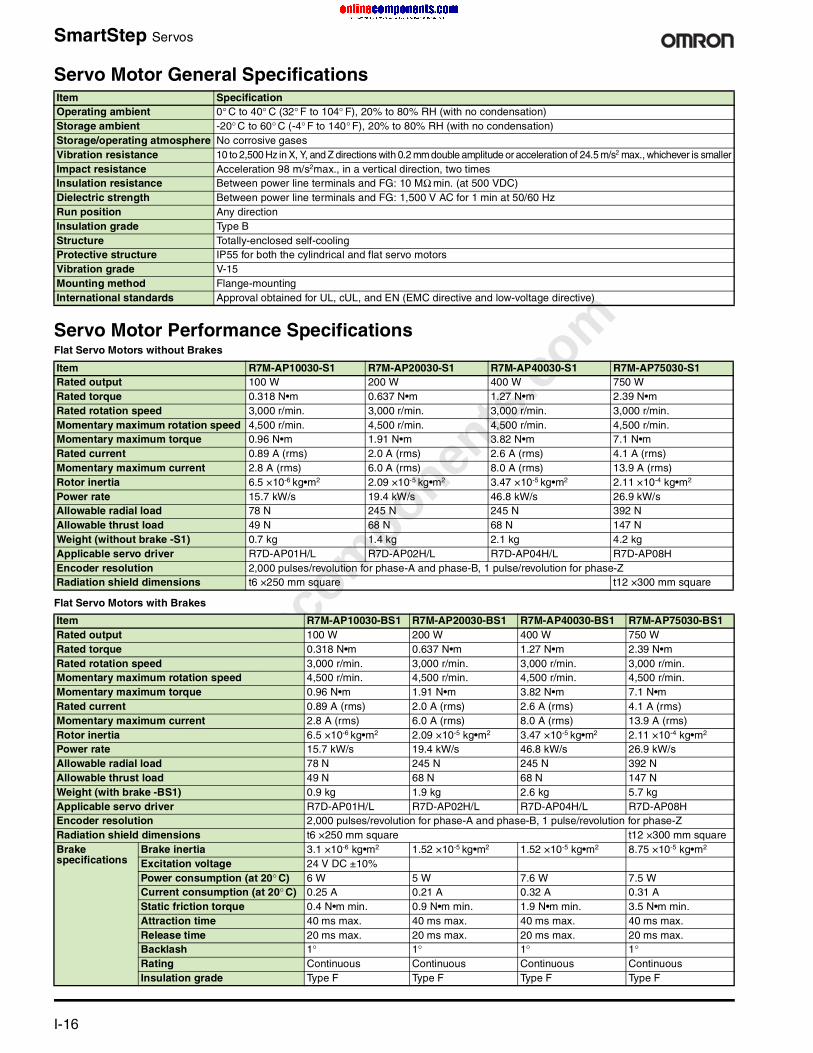
SmartStep Servos
Servo Motor General Specifications
Servo Motor Performance SpecificationsFlat Servo Motors without Brakes
Flat Servo Motors with Brakes
Item Specification Operating ambient 0° C to 40° C (32° F to 104° F), 20% to 80% RH (with no condensation)Storage ambient -20° C to 60° C (-4° F to 140° F), 20% to 80% RH (with no condensation)Storage/operating atmosphere No corrosive gasesVibration resistance 10 to 2,500 Hz in X, Y, and Z directions with 0.2 mm double amplitude or acceleration of 24.5 m/s2 max., whichever is smallerImpact resistance Acceleration 98 m/s2max., in a vertical direction, two times Insulation resistance Between power line terminals and FG: 10 MΩ min. (at 500 VDC) Dielectric strength Between power line terminals and FG: 1,500 V AC for 1 min at 50/60 Hz Run position Any direction Insulation grade Type B Structure Totally-enclosed self-cooling Protective structure IP55 for both the cylindrical and flat servo motors Vibration grade V-15 Mounting method Flange-mounting International standards Approval obtained for UL, cUL, and EN (EMC directive and low-voltage directive)
Item R7M-AP10030-S1 R7M-AP20030-S1 R7M-AP40030-S1 R7M-AP75030-S1 Rated output 100 W 200 W 400 W 750 W Rated torque 0.318 N•m 0.637 N•m 1.27 N•m 2.39 N•m Rated rotation speed 3,000 r/min. 3,000 r/min. 3,000 r/min. 3,000 r/min. Momentary maximum rotation speed 4,500 r/min. 4,500 r/min. 4,500 r/min. 4,500 r/min. Momentary maximum torque 0.96 N•m 1.91 N•m 3.82 N•m 7.1 N•m Rated current 0.89 A (rms) 2.0 A (rms) 2.6 A (rms) 4.1 A (rms) Momentary maximum current 2.8 A (rms) 6.0 A (rms) 8.0 A (rms) 13.9 A (rms) Rotor inertia 6.5 ×10⁻⁶ kg•m2 2.09 ×10⁻⁵ kg•m2 3.47 ×10⁻⁵ kg•m2 2.11 ×10⁻⁴ kg•m2 Power rate 15.7 kW/s 19.4 kW/s 46.8 kW/s 26.9 kW/s Allowable radial load 78 N 245 N 245 N 392 N Allowable thrust load 49 N 68 N 68 N 147 N Weight (without brake -S1) 0.7 kg 1.4 kg 2.1 kg 4.2 kg Applicable servo driver R7D-AP01H/L R7D-AP02H/L R7D-AP04H/L R7D-AP08HEncoder resolution 2,000 pulses/revolution for phase-A and phase-B, 1 pulse/revolution for phase-Z Radiation shield dimensions t6 ×250 mm square t12 ×300 mm square
Item R7M-AP10030-BS1 R7M-AP20030-BS1 R7M-AP40030-BS1 R7M-AP75030-BS1 Rated output 100 W 200 W 400 W 750 W Rated torque 0.318 N•m 0.637 N•m 1.27 N•m 2.39 N•m Rated rotation speed 3,000 r/min. 3,000 r/min. 3,000 r/min. 3,000 r/min. Momentary maximum rotation speed 4,500 r/min. 4,500 r/min. 4,500 r/min. 4,500 r/min. Momentary maximum torque 0.96 N•m 1.91 N•m 3.82 N•m 7.1 N•m Rated current 0.89 A (rms) 2.0 A (rms) 2.6 A (rms) 4.1 A (rms) Momentary maximum current 2.8 A (rms) 6.0 A (rms) 8.0 A (rms) 13.9 A (rms) Rotor inertia 6.5 ×10⁻⁶ kg•m2 2.09 ×10⁻⁵ kg•m2 3.47 ×10⁻⁵ kg•m2 2.11 ×10⁻⁴ kg•m2 Power rate 15.7 kW/s 19.4 kW/s 46.8 kW/s 26.9 kW/s Allowable radial load 78 N 245 N 245 N 392 N Allowable thrust load 49 N 68 N 68 N 147 N Weight (with brake -BS1) 0.9 kg 1.9 kg 2.6 kg 5.7 kg Applicable servo driver R7D-AP01H/L R7D-AP02H/L R7D-AP04H/L R7D-AP08HEncoder resolution 2,000 pulses/revolution for phase-A and phase-B, 1 pulse/revolution for phase-Z Radiation shield dimensions t6 ×250 mm square t12 ×300 mm square Brake specifications
Brake inertia 3.1 ×10⁻⁶ kg•m2 1.52 ×10⁻⁵ kg•m2 1.52 ×10⁻⁵ kg•m2 8.75 ×10⁻⁵ kg•m2 Excitation voltage 24 V DC ±10% Power consumption (at 20° C) 6 W 5 W 7.6 W 7.5 W Current consumption (at 20° C) 0.25 A 0.21 A 0.32 A 0.31 A Static friction torque 0.4 N•m min. 0.9 N•m min. 1.9 N•m min. 3.5 N•m min. Attraction time 40 ms max. 40 ms max. 40 ms max. 40 ms max. Release time 20 ms max. 20 ms max. 20 ms max. 20 ms max. Backlash 1° 1° 1° 1°Rating Continuous Continuous Continuous Continuous Insulation grade Type F Type F Type F Type F
onlinec
omponen
ts.co
m
For complete specifications and additional models: U.S. www.omron.com/oei Canada www.omron.ca I-17
SmartStep Servos
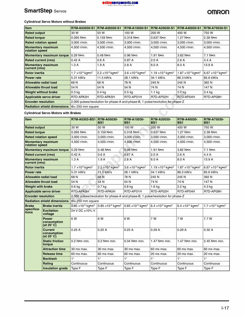
Cylindrical Servo Motors without Brakes
Cylindrical Servo Motors with Brakes
Item R7M-A03030-S1 R7M-A05030-S1 R7M-A10030-S1 R7M-A20030-S1 R7M-A40030-S1 R7M-A75030-S1
Rated output 30 W 50 W 100 W 200 W 400 W 750 W
Rated torque 0.095 N•m 0.159 N•m 0.318 N•m 0.637 N•m 1.27 N•m 2.39 N•m
Rated rotation speed 3,000 r/min. 3,000 r/min. 3,000 r/min. 3,000 r/min. 3,000 r/min. 3,000 r/min.
Momentary maximum rotation speed
4,500 r/min. 4,500 r/min. 4,500 r/min. 4,500 r/min. 4,500 r/min. 4,500 r/min.
Momentary maximum torque 0.29 N•m 0.48 N•m 0.96 N•m 1.91 N•m 3.82 N•m 7.1 N•m
Rated current (rms) 0.42 A 0.6 A 0.87 A 2.0 A 2.6 A 4.4 A
Momentary maximum current (rms)
1.3 A 1.9 A 2.8 A 6.0 A 8.0 A 13.9 A
Rotor inertia 1.7 ×10⁻⁶ kg•m2 2.2 ×10⁻⁶ kg•m2 3.6 ×10⁻⁶ kg•m2 1.19 ×10⁻⁵ kg•m2 1.87 ×10⁻⁵ kg•m2 6.67 ×10⁻⁵ kg•m2
Power rate 5.31 kW/s 11.5 kW/s 28.1 kW/s 34.1 kW/s 86.3 kW/s 85.6 kW/s
Allowable radial load 68 N 68 N 78 N 245 N 245 N 392 N
Allowable thrust load 54 N 54 N 54 N 74 N 74 N 147 N
Weight without brake 0.3 kg 0.4 kg 0.5 kg 1.1 kg 1.7 kg 3.4 kg
Applicable servo driver R7D-APA3H R7D-APA5H R7D-AP01H R7D-AP02H R7D-AP04H R7D-AP08H
Encoder resolution 2,000 pulses/revolution for phase-A and phase-B, 1 pulse/revolution for phase-Z
Radiation shield dimensions t6× 250 mm square
Item R7M-A0303-BS1 R7M-A05030-BS1
R7M-A10030-BS1
R7M-A20030-BS1
R7M-A40030-BS1
R7M-A75030-BS1
Rated output 30 W 50 W 100 W 200 W 400 W 750 W
Rated torque 0.095 N•m 0.159 N•m 0.318 N•m 0.637 N•m 1.27 N•m 2.39 N•m
Rated rotation speed 3,000 r/min. 3,000 r/min. 3,000 r/min. 3,000 r/min. 3,000 r/min. 3,000 r/min.
Momentary maximum rotation speed
4,500 r/min. 4,500 r/min. 4,500 r/min. 4,500 r/min. 4,500 r/min. 4,500 r/min.
Momentary maximum torque 0.29 N•m 0.48 N•m 0.96 N•m 1.91 N•m 3.82 N•m 7.1 N•m
Rated current (rms) 0.42 A 0.6 A 0.87 A 2.0 A 2.6 A 4.4 A
Momentary maximum current (rms)
1.3 A 1.9 A 2.8 A 6.0 A 8.0 A 13.9 A
Rotor inertia 1.7 ×10⁻⁶ kg•m2 2.2 ×10⁻⁶ kg•m2 3.6 ×10⁻⁶ kg•m2 1.19 ×10⁻⁵ kg•m2 1.87 ×10⁻⁵ kg•m2 6.67 ×10⁻⁵ kg•m2
Power rate 5.31 kW/s 11.5 kW/s 28.1 kW/s 34.1 kW/s 86.3 kW/s 85.6 kW/s
Allowable radial load 68 N 68 N 78 N 245 N 245 N 392 N
Allowable thrust load 54 N 54 N 54 N 74 N 74 N 147 N
Weight with brake 0.6 kg 0.7 kg 0.8 kg 1.6 kg 2.2 kg 4.3 kg
Applicable servo driver R7D-APA3H R7D-APA5H R7D-AP01H R7D-AP02H R7D-AP04H R7D-AP08H
Encoder resolution 2,000 pulses/revolution for phase-A and phase-B, 1 pulse/revolution for phase-Z
Radiation shield dimensions t6× 250 mm square
Brake specifica-tions
Brake inertia 0.85 ×10⁻⁶ kg•m2 0.85 ×10⁻⁶ kg•m2 0.85 ×10⁻⁶ kg•m2 6.4 ×10⁻⁶ kg•m2 6.4 ×10⁻⁶ kg•m2 1.7 ×10⁻⁵ kg•m2
Excitation voltage
24 V DC ±10% V
Power consumption (at 20° C)
6 W 6 W 6 W 7 W 7 W 7.7 W
Current consumption (at 20° C)
0.25 A 0.25 A 0.25 A 0.29 A 0.29 A 0.32 A
Static friction torque
0.2 N•m min. 0.2 N•m min. 0.34 N•m min. 1.47 N•m min. 1.47 N•m min. 2.45 N•m min.
Attraction time 30 ms max. 30 ms max. 30 ms max. 60 ms max. 60 ms max. 60 ms max.
Release time 60 ms max. 60 ms max. 60 ms max. 20 ms max. 20 ms max. 20 ms max.
Backlash 1° 1° 1° 1° 1° 1°Rating Continuous Continuous Continuous Continuous Continuous Continuous
Insulation grade Type F Type F Type F Type F Type F Type F

onlinec
omponen
ts.co
m
I-18 For complete specifications and additional models: U.S. www.omron.com/oei Canada www.omron.ca
SmartStep Servos
Dimensions
Servo Drives Dimensions (mm)
Cylindrical Servo Motors (3,000 r/min) Dimensions (mm)200 VAC: 30 W/50 W/100 W/200 W/400 W/750 WWithout brake: R7M-A03030-S1-D/A05030-S1-D/A10030-S1-D/A20030-S1-D/A40030-S1-D/A75030-S1-DWith brake: R7M-A03030-BS1-D/A05030-BS1-D/A10030-BS1-D/A20030-BS1-D/A40030-BS1-D/A75030-BS1-D
Input voltage Rating Drive model H W D
1-phase, 100 VAC and 200 VAC 30 W R7D-APA3H/L 160 55 130
50 W R7D-APA5H/L 160 55 130
100 W R7D-AP01H/L 160 55 130
200 W R7D-AP02H/L 160 55 130
400 W R7D-AP04H/L 160 75 130
1-phase, 200 VAC 750 W R7D-AP08H 160 90 180
Model Overall length Flange surface Axis end
LL LR C D1 D2 F G Z S QK b h t1
R7M-A03030-S1 69.5 25 40 46 30h7 2.5 5 Two, 4.3 dia. 6h6 14 2 2 1.2
R7M-A03030-BS1 101 25 40 46 30h7 2.5 5 Two, 4.3 dia. 6h6 14 2 2 1.2
R7M-A05030-S1 77 25 40 46 30h7 2.5 5 Two, 4.3 dia. 6h6 14 2 2 1.2
R7M-A05030-BS1 108.5 25 40 46 30h7 2.5 5 Two, 4.3 dia. 6h6 14 2 2 1.2
R7M-A10030-S1 94.5 25 40 46 30h7 2.5 5 Two, 4.3 dia. 8h6 14 3 3 1.8
R7M-A10030-BS1 135 25 40 46 30h7 2.5 5 Two, 4.3 dia. 8h6 14 3 3 1.8
R7M-A20030-S1 96.5 30 60 70 50h7 3 6 Four, 5.5 dia. 14h6 20 5 5 3
R7M-A20030-BS1 136 30 60 70 50h7 3 6 Four, 5.5 dia. 14h6 20 5 5 3
R7M-A40030-S1 124.5 30 60 70 50h7 3 6 Four, 5.5 dia. 14h6 20 5 5 3
R7M-A40030-BS1 164 30 60 70 50h7 3 6 Four, 5.5 dia. 14h6 20 5 5 3
R7M-A75030-S1 145 40 80 90 70h7 3 8 Four, 7 dia. 16h6 30 5 5 3
R7M-A75030-BS1 189.5 40 80 90 70h7 3 8 Four, 7 dia. 16h6 30 5 5 3
R7M-A@@@30(-S1) (Without Brake) *Axis End DimensionsR7M-A@@@30(-S1) (With Brake)
onlinec
omponen
ts.co
m
For complete specifications and additional models: U.S. www.omron.com/oei Canada www.omron.ca I-19
SmartStep Servos
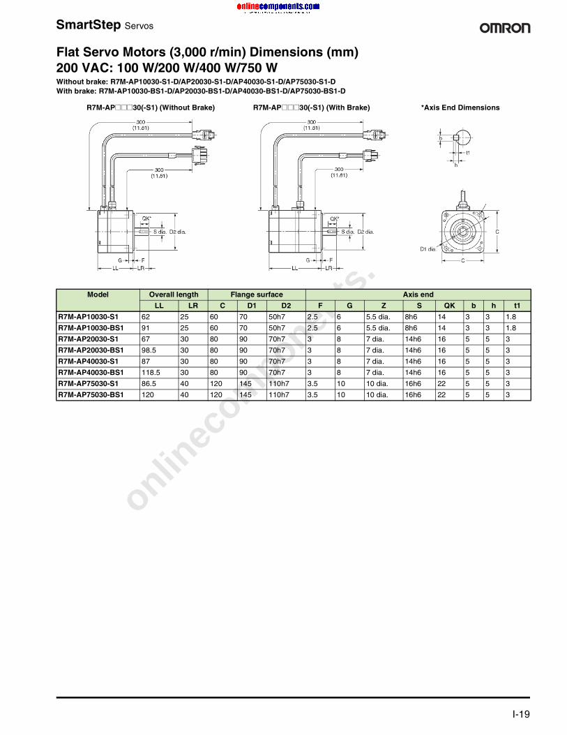
Flat Servo Motors (3,000 r/min) Dimensions (mm)200 VAC: 100 W/200 W/400 W/750 WWithout brake: R7M-AP10030-S1-D/AP20030-S1-D/AP40030-S1-D/AP75030-S1-DWith brake: R7M-AP10030-BS1-D/AP20030-BS1-D/AP40030-BS1-D/AP75030-BS1-D
Model Overall length Flange surface Axis end
LL LR C D1 D2 F G Z S QK b h t1
R7M-AP10030-S1 62 25 60 70 50h7 2.5 6 5.5 dia. 8h6 14 3 3 1.8
R7M-AP10030-BS1 91 25 60 70 50h7 2.5 6 5.5 dia. 8h6 14 3 3 1.8
R7M-AP20030-S1 67 30 80 90 70h7 3 8 7 dia. 14h6 16 5 5 3
R7M-AP20030-BS1 98.5 30 80 90 70h7 3 8 7 dia. 14h6 16 5 5 3
R7M-AP40030-S1 87 30 80 90 70h7 3 8 7 dia. 14h6 16 5 5 3
R7M-AP40030-BS1 118.5 30 80 90 70h7 3 8 7 dia. 14h6 16 5 5 3
R7M-AP75030-S1 86.5 40 120 145 110h7 3.5 10 10 dia. 16h6 22 5 5 3
R7M-AP75030-BS1 120 40 120 145 110h7 3.5 10 10 dia. 16h6 22 5 5 3
R7M-AP@@@30(-S1) (Without Brake) R7M-AP@@@30(-S1) (With Brake) *Axis End Dimensions
onlinec
omponen
ts.co
m
I-20 For complete specifications and additional models: U.S. www.omron.com/oei Canada www.omron.ca
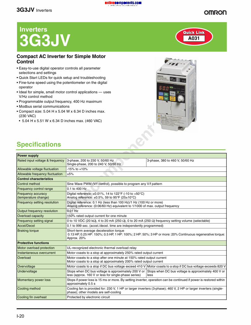
3G3JV Inverters
Compact AC Inverter for Simple Motor Control• Easy-to-use digital operator controls all parameter
selections and settings• Quick Start LEDs for quick setup and troubleshooting• Fine-tune speed using the potentiometer on the digital
operator • Ideal for simple, small motor control applications — uses
V/Hz control method• Programmable output frequency, 400 Hz maximum• Modbus serial communications• Compact size: 5.04 H x 5.04 W x 6.34 D inches max.
(230 VAC) • 5.04 H x 5.51 W x 6.34 D inches max. (460 VAC)
Inverters
3G3JV A031
Specifications
Power supply
Rated input voltage & frequency 3-phase, 200 to 230 V, 50/60 Hz Single-phase, 200 to 240 V, 50/60 Hz
3-phase, 380 to 460 V, 50/60 Hz
Allowable voltage fluctuation -15% to +10%
Allowable frequency fluctuation ±5%
Control characteristics
Control method Sine Wave PWM (V/f control), possible to program any V/f pattern
Frequency control range 0.1 to 400 Hz
Frequency accuracy (temperature change)
Digital reference: ±0.01%, 14 to 122°F (-10 to +50°C)Analog reference: ±0.5%, 59 to 95°F (25±10°C)
Frequency setting resolution Digital reference: 0.1 Hz (less than 100 Hz)/1 Hz (100 Hz or more)Analog reference: (0:06/60 Hz) equivalent to 1/1000 of max. output frequency
Output frequency resolution 0.01 Hz
Overload capacity 150% rated output current for one minute
Frequency setting signal 0 to 10 VDC (20 kΩ), 4 to 20 mA (250 Ω), 0 to 20 mA (250 Ω) frequency setting volume (selectable)
Accel/Decel 0.1 to 999 sec. (accel./decel. time are independently programmed)
Braking torque Short-term average deceleration torque 0.13 HP, 0.25 HP: 150%; 0.5 HP, 1 HP: 100%; 2 HP: 50%; 3 HP or more: 20% Continuous regenerative torque: Approx. 20%
Protective functions
Motor overload protection UL-recognized electronic thermal overload relay
Instantaneous overcurrent Motor coasts to a stop at approximately 250% rated output current
Overload Motor coasts to a stop after one minute at 150% rated output currentMotor coasts to a stop at approximately 200% rated output current
Overvoltage Motor coasts to a stop if DC bus voltage exceed 410 V Motor coasts to a stop if DC bus voltage exceeds 820 V
Undervoltage Stops when DC bus voltage is approximately 200 V or less (approx. 160 V or less for single-phase series)
Stops when DC bus voltage is approximately 400 V or less
Momentary power loss Stops if power loss is 15 ms or more. By setting inverter, operation can be continued if power is restored within approximately 0.5 s
Cooling method Cooling fan is provided for: 230 V, 1 HP or larger inverters (3-phase); 460 V, 2 HP or larger inverters (single-phase); other models are self-cooling
Cooling fin overheat Protected by electronic circuit

onlinec
omponen
ts.co
m
For complete specifications and additional models: U.S. www.omron.com/oei Canada www.omron.ca I-21
3G3JV Inverters
3G3JV Inverter Ordering Information
Manuals
Cooling fan fault Protected by electronic circuit (fan-stalling detection)
Stall prevention Individual levels during acceleration/running, enable/disable provided during deceleration
Ground fault Protected by electronic circuit (rated output current level)
Power charge indication RUN lamp stays ON or digital operator LED stays ON. (Charge LED is provided for 460 V) ON until the DC bus voltage becomes 50 V or less
Environmental conditions
Enclosure rating Open chassis: IP20
Location Indoor (free from corrosive gases and dust)
Ambient temperature Open chassis: 14 to 122°F (-10 to +50°C), not frozen
Storage temperature -4 to 140°F (-20 to 60°C)
Humidity 95% RH (Non-condensing)
Elevation 1,000 m (3,281 feet) or below
Wiring distance 328 ft (100 m) or less between inverter and motor
Vibration 9.8 m/s2 (1G) less than 20 Hz, up to 1.96 m/s2 (0.2G) at 20 to 50 Hz
Other functions
Multi-function inputs Four of the following input signals are selectable: Reverse run (3-wire sequence), fault reset, external fault (NO/NC contact input), multi-step speed operation, Jog command, accel/decel time select, external baseblock (NO/NC contact input), speed search command, accel/decel hold command, LOCAL/REMOTE selection, communication/control circuit terminal selection, emergency stop fault, emergency stop alarm.
Multi-function outputs Following output signals are selectable (1 NO/NC contact output): Fault, running, zero speed, at frequency, frequency detection (output frequency = or = set value), during overtorque detection, minor error, during baseblock, operation mode, inverter run ready, during fault retry, during under-voltage, during speed search, data output through communication.
Standard functions Full-range automatic torque boost, slip compensation, DC injection braking current/time at start/stop frequency reference bias/gain, frequency reference with built-in potentiometer, MEMOBUS communications (RS-485/422, max. 19.2 K bps) capable with optional unit.
Description Enclosure Rating Model
HP Voltage Phase
Compact inverter with V/Hz control
NEMA 1 1/8 240 1 3G3JV-AB001-A
1/4 240 1 3G3JV-AB002-A
3/4 240 1 3G3JV-AB004-A
1 240 1 3G3JV-AB007-A
2 240 1 3G3JV-AB015-A
1/8 230 3 3G3JV-A2001-A
1/4 230 3 3G3JV-A2002-A
3/4 230 3 3G3JV-A2004-A
1 230 3 3G3JV-A2007-A
2 230 3 3G3JV-A2015-A
3 230 3 3G3JV-A2022-A
5 230 3 3G3JV-A2037-A
Open chassis 1/2 460 3 3G3JV-A4002-A
1 460 3 3G3JV-A4004-A
2 460 3 3G3JV-A4007-A
3 460 3 3G3JV-A4015-A
3 460 3 3G3JV-A4022-A
5 460 3 3G3JV-A4037-A
Item Description Model
User’s manual 3G3JV User’s manual I528-E3-1
Specifications (Continued)

onlinec
omponen
ts.co
m
I-22 For complete specifications and additional models: U.S. www.omron.com/oei Canada www.omron.ca
3G3MV Inverters
Versatile Compact Inverter Offers Loop Vector and V/Hz Control• Intuitive digital operator controls all parameter selections
and settings• Quick Start LEDs for fast setup and troubleshooting• Standard PID control• Modbus serial communications standard• DeviceNet communications unit (optional) allows remote
monitoring of Run/Stop status and operating conditions, and making changes to set values
• Fine-tune speed using the potentiometer on the digital operator
• User-selectable open loop vector and V/Hz control methods• NEMA 4X models meet requirements for tough washdown
and dust-tight environments• NEMA 1 models available• Compact size: Single phase, 230 VAC: 148 H x 170 W x
180 D mm max.• Three-phase, 230 VAC: 260 H x 180 W x 170 D mm max.• Three-phase, 460 VAC: 260 H x 180 W x 170 D mm max.
• Integrate a full-featured PLC into 3G3MV inverters with 6 input/4 output points, encoder input, interrupt inputs and pulse outputs; dual port RAM for 200 transfers per second; eliminates point-to-point wiring
Specifications
Inverters
3G3MV A032
General SpecificationsPower supply
Rated input voltage & frequency 3-phase, 200 to 230 V, 50/60 Hz Single-phase, 200 to 240 V, 50/60 Hz
3-phase, 380 to 460 V, 50/60 Hz
Allowable voltage fluctuation -15% to +10%
Allowable frequency fluctuation ±5%
Control characteristics
Control method Sine wave PWM (V/f control or voltage vector control, selectable); possible to program any V/f pattern
Frequency control range 0.1 to 400 Hz
Frequency accuracy (temperature change)
Digital reference: ±0.01%, 14 to 122°F (-10 to +50°C)Analog reference: ±0.5%, 59 to 95°F (25±10°C)
Frequency setting resolution Digital reference: 0.1 Hz (less than 100 Hz)/0.1 Hz (100 Hz or more)Analog reference: (0:06/60 Hz) equivalent to 1/1000 of max. output frequency
Output frequency resolution 0.01 Hz
Overload capacity 150% rated output current for one minute
Frequency setting signal 0 to 10 VDC (20 kΩ), 4 to 20 mA (250 Ω), 0 to 20 mA (250 Ω) pulse train input, frequency setting potentiometer (Selectable)
Accel/Decel 0.01 to 6000 seconds (accel/decel time are independently programmed 2 types)
Braking torque Short-term average deceleration torque:0.1, 0.25 kW (0.13 HP, 0.25 HP): 150%; 0.55, 1.1 kW): (0.5 HP, 1 HP): 100% 1.5 kW (2 HP): 50%; 2.2 kW (3 HP) or more: 20%Continuous regenerative torque: Approx. 20% (150% with optional braking resistor, braking transistor built-in)
onlinec
omponen
ts.co
m
For complete specifications and additional models: U.S. www.omron.com/oei Canada www.omron.ca I-23
3G3MV Inverters
Inverter PLC Specifications
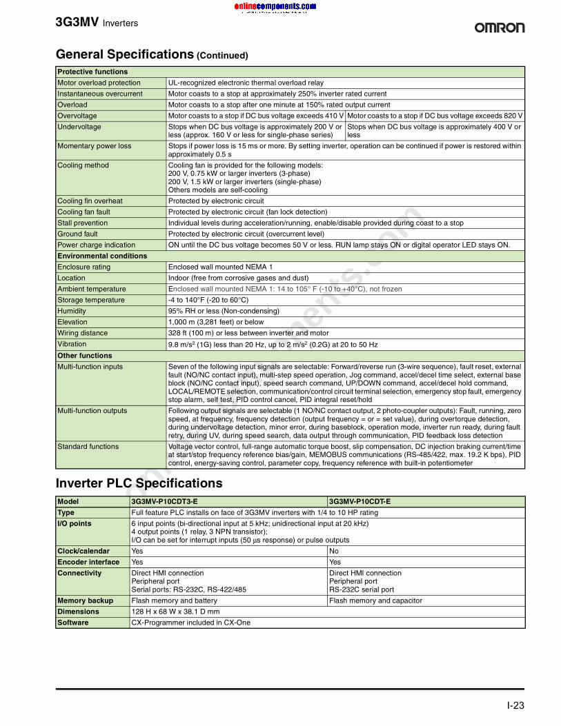
Protective functions
Motor overload protection UL-recognized electronic thermal overload relay
Instantaneous overcurrent Motor coasts to a stop at approximately 250% inverter rated current
Overload Motor coasts to a stop after one minute at 150% rated output current
Overvoltage Motor coasts to a stop if DC bus voltage exceeds 410 V Motor coasts to a stop if DC bus voltage exceeds 820 V
Undervoltage Stops when DC bus voltage is approximately 200 V or less (approx. 160 V or less for single-phase series)
Stops when DC bus voltage is approximately 400 V or less
Momentary power loss Stops if power loss is 15 ms or more. By setting inverter, operation can be continued if power is restored within approximately 0.5 s
Cooling method Cooling fan is provided for the following models: 200 V, 0.75 kW or larger inverters (3-phase) 200 V, 1.5 kW or larger inverters (single-phase) Others models are self-cooling
Cooling fin overheat Protected by electronic circuit
Cooling fan fault Protected by electronic circuit (fan lock detection)
Stall prevention Individual levels during acceleration/running, enable/disable provided during coast to a stop
Ground fault Protected by electronic circuit (overcurrent level)
Power charge indication ON until the DC bus voltage becomes 50 V or less. RUN lamp stays ON or digital operator LED stays ON.
Environmental conditions
Enclosure rating Enclosed wall mounted NEMA 1
Location Indoor (free from corrosive gases and dust)
Ambient temperature Enclosed wall mounted NEMA 1: 14 to 105° F (-10 to +40°C), not frozen
Storage temperature -4 to 140°F (-20 to 60°C)
Humidity 95% RH or less (Non-condensing)
Elevation 1,000 m (3,281 feet) or below
Wiring distance 328 ft (100 m) or less between inverter and motor
Vibration 9.8 m/s2 (1G) less than 20 Hz, up to 2 m/s2 (0.2G) at 20 to 50 Hz
Other functions
Multi-function inputs Seven of the following input signals are selectable: Forward/reverse run (3-wire sequence), fault reset, external fault (NO/NC contact input), multi-step speed operation, Jog command, accel/decel time select, external base block (NO/NC contact input), speed search command, UP/DOWN command, accel/decel hold command, LOCAL/REMOTE selection, communication/control circuit terminal selection, emergency stop fault, emergency stop alarm, self test, PID control cancel, PID integral reset/hold
Multi-function outputs Following output signals are selectable (1 NO/NC contact output, 2 photo-coupler outputs): Fault, running, zero speed, at frequency, frequency detection (output frequency = or = set value), during overtorque detection, during undervoltage detection, minor error, during baseblock, operation mode, inverter run ready, during fault retry, during UV, during speed search, data output through communication, PID feedback loss detection
Standard functions Voltage vector control, full-range automatic torque boost, slip compensation, DC injection braking current/time at start/stop frequency reference bias/gain, MEMOBUS communications (RS-485/422, max. 19.2 K bps), PID control, energy-saving control, parameter copy, frequency reference with built-in potentiometer
Model 3G3MV-P10CDT3-E 3G3MV-P10CDT-E
Type Full feature PLC installs on face of 3G3MV inverters with 1/4 to 10 HP rating
I/O points 6 input points (bi-directional input at 5 kHz; unidirectional input at 20 kHz)4 output points (1 relay, 3 NPN transistor);I/O can be set for interrupt inputs (50 µs response) or pulse outputs
Clock/calendar Yes No
Encoder interface Yes Yes
Connectivity Direct HMI connectionPeripheral port Serial ports: RS-232C, RS-422/485
Direct HMI connectionPeripheral portRS-232C serial port
Memory backup Flash memory and battery Flash memory and capacitor
Dimensions 128 H x 68 W x 38.1 D mm
Software CX-Programmer included in CX-One
General Specifications (Continued)
onlinec
omponen
ts.co
m
I-24 For complete specifications and additional models: U.S. www.omron.com/oei Canada www.omron.ca
3G3MV Inverters
Ordering Information
MV Inverter
Accessories
Support Software and Programming Devices
Manuals
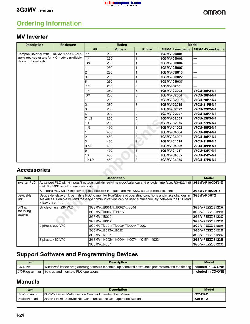
Description Enclosure Rating ModelHP Voltage Phase NEMA 1 enclosure NEMA 4X enclosure
Compact inverter with open loop vector and V/Hz control methods
NEMA 1 and NEMA 4X models available
1/8 230 1 3G3MV-CB001 — 1/4 230 1 3G3MV-CB002 — 3/4 230 1 3G3MV-CB004 —1 230 1 3G3MV-CB007 —2 230 1 3G3MV-CB015 —3 230 1 3G3MV-CB022 —5 230 1 3G3MV-CB037 — 1/8 230 3 3G3MV-C2001 — 1/4 230 3 3G3MV-C2002 V7CU-20P2-N4 3/4 230 3 3G3MV-C2004 V7CU-20P4-N41 230 3 3G3MV-C2007 V7CU-20P7-N42 230 3 3G3MV-C2015 V7CU-21P5-N43 230 3 3G3MV-C2022 V7CU-22P2-N45 230 3 3G3MV-C2037 V7CU-23P7-N47 1/2 230 3 3G3MV-C2055 V7CU-25P5-N410 230 3 3G3MV-C2075 V7CU-27P5-N4 1/2 460 3 3G3MV-C4002 V7CU-40P2-N41 460 3 3G3MV-C4004 V7CU-40P4-N42 460 3 3G3MV-C4007 V7CU-40P7-N43 460 3 3G3MV-C4015 V7CU-41P5-N43 1/2 460 3 3G3MV-C4022 V7CU-42P2-N45 460 3 3G3MV-C4037 V7CU-43P7-N410 460 3 3G3MV-C4055 V7CU-45P5-N412 1/2 460 3 3G3MV-C4075 V7CU-47P5-N4
Item Description ModelInverter PLC Advanced PLC with 6 inputs/4 outputs; built-in real-time clock/calendar and encoder interface; RS-422/485
and RS-232C serial communications3G3MV-P10CDT3-E
Standard PLC with 6 inputs/4outputs, encoder interface and RS-232C serial communications 3G3MV-P10CDT-E DeviceNet unit
DeviceNet slave unit; permits a PLC to monitor Run/Stop and operating conditions and make changes in set values. Remote I/O and message communications can be used simultaneously between the PLC and 3G3MV inverter.
3G3MV-PDRT2
DIN rail mounting bracket
Single-phase, 230 VAC 3G3MV-@B001/-@B002/-@B004 3G3IV-PEZZ08122A 3G3MV-@B007/-@B015 3G3IV-PEZZ08122B3G3MV-@B022 3G3IV-PEZZ08122C3G3MV-@B037 3G3IV-PEZZ08122D
3-phase, 230 VAC 3G3MV-@2001/-@2002/-@2004/-@2007 3G3IV-PEZZ08122A 3G3MV-@2015/-@2022 3G3IV-PEZZ08122B3G3MV-@2037 3G3IV-PEZZ08122C
3-phase, 460 VAC 3G3MV-@4002/-@4004/-@4007/-@4015/-@4022 3G3IV-PEZZ08122B3G3MV-@4037 3G3IV-PEZZ08122C
Item Description ModelCX-Drive Windows®-based programming software for setup; uploads and downloads parameters and monitoring Included in CX-ONE CX-Programmer Sets up and monitors PLC operations Included in CX-ONE
Item Description ModelUser’s manual 3G3MV Series Multi-function Compact Inverter User Manual I527-E3-2DeviceNet unit 3G3MV-PDRT2 DeviceNet Communications Unit Operation Manual I539-E1-2

onlinec
omponen
ts.co
m
For complete specifications and additional models: U.S. www.omron.com/oei Canada www.omron.ca I-25
G5+ Inverters
Flux Vector Inverter 600V Constant Torque for Machine AutomationThe G5+ Inverter offers ultra-fast processing. All systems are controlled by a 32-bit, 20 MHz RISC processor, which executes basic instructions in one clock cycle. The processor uses an innovative "5 stage pipeline architecture" which allows the processor to perform 5 instructions at one time. This results in a rating of 16 MIPS (Million Instructions Per Second).
• The control board is common to all chassis inverter sizes• Field upgradeable Flash ROM• Four programmable control modes to suit any specific
application.• Built-in motor auto-tuning for easy start-up• 2 sets of motor constants — very useful in machine tools
applications• 2 Line x 16 characters alphanumeric operator makes
programming easier to understand• Dedicated Serial Communication Port allows to network the
G5+ with other devices• PID function with feedback loop• Energy savings software helps reduce power consumption• Customized CASE software for specific applications
Inverters
G5+ G089
Canada Only
Specifications
Power supplyRated input voltage & frequency 3-phase, 500/575/600 VAC, 50/60Hz
Allowable voltage fluctuation -15% of 500 VAC; +10% of 600 VACAllowable frequency fluctuation ±5%
Control characteristicsControl method Sine coded PWM (digital flux vector)
Starting torque 150% below 1 Hz (150% at 0 RPM with PG)
Speed control range 100:1 (1000:1 with PG)
Speed control accuracy ±0.2% (±0.02% with PG)
Speed response 5 Hz (30 Hz with PG)
Torque limit Can be set by parameter: 4 steps available
Torque accuracy ±5%
Torque response 20 Hz (40 Hz with PG)
Frequency control range 0.1 to 400 Hz
Frequency accuracy Digital Command: ±0.01%, +14° to 104°F (-10° to 40°C)Analog Command: ±0.1%, 77±18°F (25±10°C)
Frequency setting resolution Digital Operator Reference: 0.01 Hz (12 bits)Analog Reference: 0.03 Hz/60 Hz (14 bits)
Output frequency resolution 0.01 Hz
Overload capacity 150% rated output current for one minute
Frequency setting signal -10 to +10 V, 0 to +10 V, 4 to 20 mA
Accel/Decel 0.01 to 6000.0 seconds (Accel/Decel time setting independently; 4 steps available)
Braking torque Approximately 20% (Approximately 125% when using braking resistor*) *Set l3-04=0 (Stall Prevention selection during decel is disabled) when connecting braking transistors or braking resistor.
Protective functionsMotor overload protection UL-recognized electronic thermal overload relay
onlinec
omponen
ts.co
m
I-26 For complete specifications and additional models: U.S. www.omron.com/oei Canada www.omron.ca
G5+ Inverters
Ordering Information
G5+ Inverter
Instantaneous overcurrent Motor coasts to a stop at approximately 200% rated output current
Fuse protection Motor coasts to a stop at blown fuse
Overload Motor coasts to a stop after one minute at 150% rated output current
Overvoltage Motor coasts to a stop if converter output voltage exceeds 1,050 VDC at 600 V inputUndervoltage Motor coasts to a stop if converter output voltage drops to 546 VDC or below at 600 V input
Momentary power loss Immediate stop after 15ms or longer power loss (setting mode before shipment)
Fin overheat Thermostat
Stall prevention Stall prevention during accel/decel and constant speed operation
Ground fault Provided by electronic circuit (overcurrent level)
Power charge indication Charge led stays ON until bus voltage drops below 50 VDC
Environmental conditionsLocation Indoor (Protected from corrosive gases and dust)
Ambient temperature +14 to 104°F (-10 to 40°C) for NEMA 1 type+14 to 113°F (-10 to 45°C) for Open Chassis Type
Storage temperature -4 to 140°F (-20 to 60°C)Humidity 95% RH (Non-condensing)
Elevation 1,000 m (3,281 feet) or below
Wiring distance 328 ft (100 m) or less between inverter and motor
Vibration 9.8 m/s2 (1G) less than 20 Hz, up to 1.96 m/s2 (0.2G) at 20 to 50 Hz
Other functionsInput signals 3 Analog Inputs available (0 to 10 V, -10 to +10 V, 4 to 20 mA)
Multi-function inputs 8 Digital Inputs with 6 programmable for functions such as: 3 wire sequencing (2 wire is standard), multi-step speed operation, fault reset, external fault (NO or NC), jog, accel/decel time select, MOP function, speed search command, Local/Remote selection, motor 1 or 2 selection, PID disable, PID reset, trim increase or decrease, fast stop, analog signal selection, and many others
Output signals 2 Analog Outputs (0 to 10 V) with 25 different settable functions
Multi-function outputs 4 Digital Outputs (Form C fault contacts plus 3 programmable outputs [1 form A, 2 open collector]). Programmable Output functions available are: run signal, zero speed, frequency agree (2), frequency detection (4), torque level detection (2), timer output, at current/torque limit, regenerating, minor or major fault, DB overheat, loss of reference, and many others.
Standard functions Settable for V/Hz, open loop vector, or closed loop vector, DC injection braking, PID control, zero servo mode, energy saving mode, 4 accel/decel times with S-curve, 8 preset speeds, slip and torque compensation, 3 jump frequencies, stall prevention, auto restart, and many other standard features.
Description Enclosure Rating Model Flux vector inverter with constant torque control
NEMA 1 2 HP, 3.5 A, 575 VAC G5M-51P5-N1 3 HP, 4.1 A, 575 VAC G5M-52P2-N1 5 HP, 6.3 A, 575 VAC G5M-53P7-N1 7.5 HP, 9.8A, 575 VAC G5M-55P5-N1 10 HP, 12.5 A, 575 VAC G5M-57P5-N1 15 HP, 17.0 A, 575 VAC G5M-5011-N1 20 HP, 22.0 A, 575 VAC G5M-5015-N1 25 HP, 27.0 A, 575 VAC G5M-5018-N1 30 HP, 32.0 A, 575 VAC G5M-5022-N1 40 HP, 41.0 A, 575 VAC G5M-5030-N1 50 HP, 52.0 A, 575 VAC G5M-5037-N1 60 HP, 62.0 A, 575 VAC G5M-5045-N1 75 HP, 77 A, 575 VAC G5M-5055-N1 100 HP, 99 A, 575 VAC G5M-5075-N1
Open chassis 120 HP, 130 A, 575 VAC G5M-5090-N0 150 HP, 172 A, 575 VAC G5M-5110-N0 200 HP, 200 A, 575 VAC G5M-5160-N0
Specifications (Continued)

onlinec
omponen
ts.co
m
For complete specifications and additional models: U.S. www.omron.com/oei Canada www.omron.ca I-27
G5+ Inverters
Support Software and Programming Devices
Manuals
Item Description Model
CX-Drive Windows®-based programming software for sets up Uploads and downloads parameters and monitoring
Included in CX-ONE
Item Description Model
User’s manual G5+ User’s manual IM-G5

onlinec
omponen
ts.co
m
I-28 For complete specifications and additional models: U.S. www.omron.com/oei Canada www.omron.ca
P5+ Inverters
Powerful 600V Variable Torque Inverter for Building Automation• Energy savings software helps reduce power consumption• Built-in PID function allows feedback loop• Highly programmable with 116 parameters• UL listed electronic thermal overload that eliminates external
devices• Speed search function restarts a coasting motor without
stopping it, after a power loss • Multi-function Inputs (5) & Outputs (3) for increased flexibility• 5 preset speeds (4 speeds + jog) allows multi-step operation• Stall prevention/Current limit prevent overcurrent trips and
motor stall• Momentary power loss ride-through Continue the operation,
after recovery from a momentary power loss• Critical frequency lockouts (2) to avoid mechanical
resonance (as in cooling towers)• Alphanumeric digital operator makes programming easier to
understand• Communications cards for MetaSys N2, Apogee, and
Echelon LONworks building automation protocols. Use optional communication card Modbus RTU to control up to 31 Drives
• Common control board across all models• 3rd generation IGBT output section• Terminals for optional DC link reactor (from 2HP / 600V up to
20 HP / 600V)• Built-in braking IGBT (from 2HP / 600V up to 30 HP / 600V)• Built-in RS-232C port for direct connection to programming
tools
Inverters
P5+ G089A
Canada Only
SpecificationsPower Supply600V rated input voltage & frequency
3-phase, 500/575/600 VAC, 50/60 Hz
Allowable voltage fluctuation -15% of 500 VAC, +10% of 600 VACAllowable frequency fluctuation ±5%Control CharacteristicsControl method Sine Wave PWMFrequency control range 0.1 to 400 HzFrequency accuracy Digital Operator Reference: 0.01%
Analog Reference: 0.1%Frequency setting resolution Digital Operator Reference: 0.01 Hz
Analog Reference: 0.06 Hz/60 HzOutput frequency resolution 0.01 HzOverload capacity 120% rated output current for one minute (150% for constant torque rating)Frequency setting signal 0 to +10 V (20 kΩ), 4 to 20 mA (250 Ω)Accel/Decel 0.01 to 3600.0 sec (Accel/Decel time setting independently; 0.1sec)Braking torque Approximately 20%Protective FunctionsMotor overload protection UL recognized internal electronic thermal overload relay (I2t)
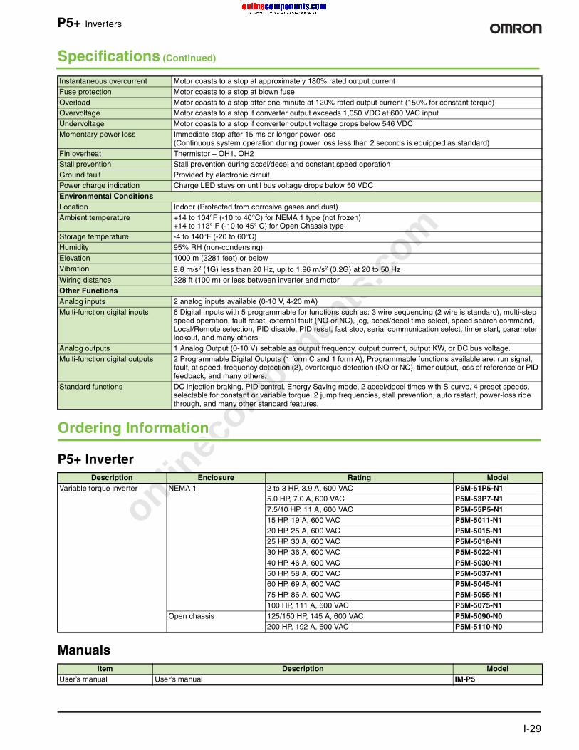
onlinec
omponen
ts.co
m
For complete specifications and additional models: U.S. www.omron.com/oei Canada www.omron.ca I-29
P5+ Inverters
Ordering Information
P5+ Inverter
Manuals
Instantaneous overcurrent Motor coasts to a stop at approximately 180% rated output currentFuse protection Motor coasts to a stop at blown fuseOverload Motor coasts to a stop after one minute at 120% rated output current (150% for constant torque)Overvoltage Motor coasts to a stop if converter output exceeds 1,050 VDC at 600 VAC inputUndervoltage Motor coasts to a stop if converter output voltage drops below 546 VDCMomentary power loss Immediate stop after 15 ms or longer power loss
(Continuous system operation during power loss less than 2 seconds is equipped as standard)Fin overheat Thermistor – OH1, OH2Stall prevention Stall prevention during accel/decel and constant speed operationGround fault Provided by electronic circuitPower charge indication Charge LED stays on until bus voltage drops below 50 VDCEnvironmental ConditionsLocation Indoor (Protected from corrosive gases and dust)Ambient temperature +14 to 104°F (-10 to 40°C) for NEMA 1 type (not frozen)
+14 to 113° F (-10 to 45° C) for Open Chassis typeStorage temperature -4 to 140°F (-20 to 60°C) Humidity 95% RH (non-condensing)Elevation 1000 m (3281 feet) or belowVibration 9.8 m/s2 (1G) less than 20 Hz, up to 1.96 m/s2 (0.2G) at 20 to 50 HzWiring distance 328 ft (100 m) or less between inverter and motorOther FunctionsAnalog inputs 2 analog inputs available (0-10 V, 4-20 mA)Multi-function digital inputs 6 Digital Inputs with 5 programmable for functions such as: 3 wire sequencing (2 wire is standard), multi-step
speed operation, fault reset, external fault (NO or NC), jog, accel/decel time select, speed search command, Local/Remote selection, PID disable, PID reset, fast stop, serial communication select, timer start, parameter lockout, and many others.
Analog outputs 1 Analog Output (0-10 V) settable as output frequency, output current, output KW, or DC bus voltage.Multi-function digital outputs 2 Programmable Digital Outputs (1 form C and 1 form A), Programmable functions available are: run signal,
fault, at speed, frequency detection (2), overtorque detection (NO or NC), timer output, loss of reference or PID feedback, and many others.
Standard functions DC injection braking, PID control, Energy Saving mode, 2 accel/decel times with S-curve, 4 preset speeds, selectable for constant or variable torque, 2 jump frequencies, stall prevention, auto restart, power-loss ride through, and many other standard features.
Description Enclosure Rating Model Variable torque inverter NEMA 1 2 to 3 HP, 3.9 A, 600 VAC P5M-51P5-N1
5.0 HP, 7.0 A, 600 VAC P5M-53P7-N1 7.5/10 HP, 11 A, 600 VAC P5M-55P5-N1 15 HP, 19 A, 600 VAC P5M-5011-N1 20 HP, 25 A, 600 VAC P5M-5015-N1 25 HP, 30 A, 600 VAC P5M-5018-N1 30 HP, 36 A, 600 VAC P5M-5022-N1 40 HP, 46 A, 600 VAC P5M-5030-N1 50 HP, 58 A, 600 VAC P5M-5037-N1 60 HP, 69 A, 600 VAC P5M-5045-N1 75 HP, 86 A, 600 VAC P5M-5055-N1 100 HP, 111 A, 600 VAC P5M-5075-N1
Open chassis 125/150 HP, 145 A, 600 VAC P5M-5090-N0 200 HP, 192 A, 600 VAC P5M-5110-N0
Item Description ModelUser’s manual User’s manual IM-P5
Specifications (Continued)
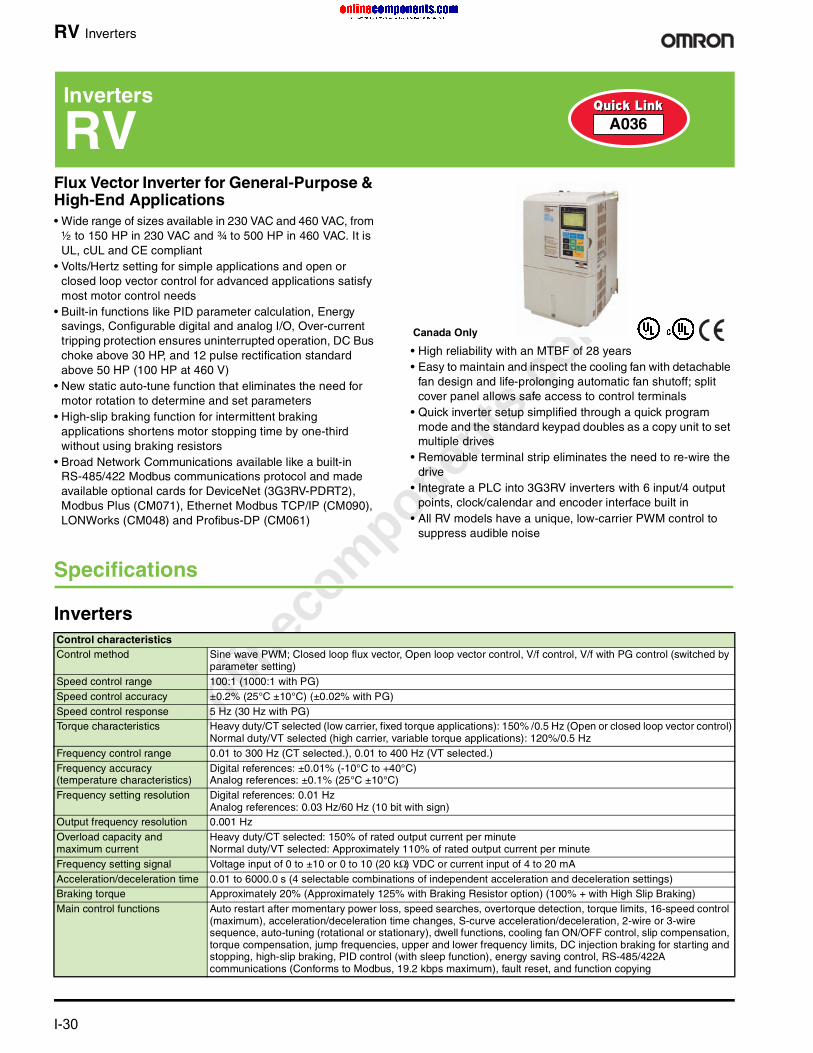
onlinec
omponen
ts.co
m
I-30 For complete specifications and additional models: U.S. www.omron.com/oei Canada www.omron.ca
RV Inverters
Flux Vector Inverter for General-Purpose & High-End Applications• Wide range of sizes available in 230 VAC and 460 VAC, from
½ to 150 HP in 230 VAC and ¾ to 500 HP in 460 VAC. It is UL, cUL and CE compliant
• Volts/Hertz setting for simple applications and open or closed loop vector control for advanced applications satisfy most motor control needs
• Built-in functions like PID parameter calculation, Energy savings, Configurable digital and analog I/O, Over-current tripping protection ensures uninterrupted operation, DC Bus choke above 30 HP, and 12 pulse rectification standard above 50 HP (100 HP at 460 V)
• New static auto-tune function that eliminates the need for motor rotation to determine and set parameters
• High-slip braking function for intermittent braking applications shortens motor stopping time by one-third without using braking resistors
• Broad Network Communications available like a built-in RS-485/422 Modbus communications protocol and made available optional cards for DeviceNet (3G3RV-PDRT2), Modbus Plus (CM071), Ethernet Modbus TCP/IP (CM090), LONWorks (CM048) and Profibus-DP (CM061)
• High reliability with an MTBF of 28 years• Easy to maintain and inspect the cooling fan with detachable
fan design and life-prolonging automatic fan shutoff; split cover panel allows safe access to control terminals
• Quick inverter setup simplified through a quick program mode and the standard keypad doubles as a copy unit to set multiple drives
• Removable terminal strip eliminates the need to re-wire the drive
• Integrate a PLC into 3G3RV inverters with 6 input/4 output points, clock/calendar and encoder interface built in
• All RV models have a unique, low-carrier PWM control to suppress audible noise
Specifications
Inverters
Inverters
RV A036
Canada Only
Control characteristicsControl method Sine wave PWM; Closed loop flux vector, Open loop vector control, V/f control, V/f with PG control (switched by
parameter setting)Speed control range 100:1 (1000:1 with PG)Speed control accuracy ±0.2% (25°C ±10°C) (±0.02% with PG)Speed control response 5 Hz (30 Hz with PG)Torque characteristics Heavy duty/CT selected (low carrier, fixed torque applications): 150% /0.5 Hz (Open or closed loop vector control)
Normal duty/VT selected (high carrier, variable torque applications): 120%/0.5 HzFrequency control range 0.01 to 300 Hz (CT selected.), 0.01 to 400 Hz (VT selected.)Frequency accuracy (temperature characteristics)
Digital references: ±0.01% (-10°C to +40°C)Analog references: ±0.1% (25°C ±10°C)
Frequency setting resolution Digital references: 0.01 HzAnalog references: 0.03 Hz/60 Hz (10 bit with sign)
Output frequency resolution 0.001 HzOverload capacity and maximum current
Heavy duty/CT selected: 150% of rated output current per minute Normal duty/VT selected: Approximately 110% of rated output current per minute
Frequency setting signal Voltage input of 0 to ±10 or 0 to 10 (20 kΩ) VDC or current input of 4 to 20 mAAcceleration/deceleration time 0.01 to 6000.0 s (4 selectable combinations of independent acceleration and deceleration settings)Braking torque Approximately 20% (Approximately 125% with Braking Resistor option) (100% + with High Slip Braking)Main control functions Auto restart after momentary power loss, speed searches, overtorque detection, torque limits, 16-speed control
(maximum), acceleration/deceleration time changes, S-curve acceleration/deceleration, 2-wire or 3-wire sequence, auto-tuning (rotational or stationary), dwell functions, cooling fan ON/OFF control, slip compensation, torque compensation, jump frequencies, upper and lower frequency limits, DC injection braking for starting and stopping, high-slip braking, PID control (with sleep function), energy saving control, RS-485/422A communications (Conforms to Modbus, 19.2 kbps maximum), fault reset, and function copying
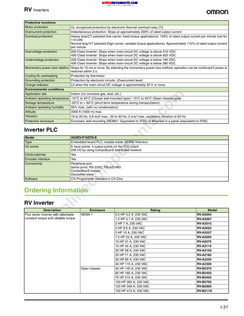
onlinec
omponen
ts.co
m
For complete specifications and additional models: U.S. www.omron.com/oei Canada www.omron.ca I-31
RV Inverters
Inverter PLC
Ordering Information
Protective functionsMotor protection UL recognized protection by electronic thermal overload relay (i2t).Overcurrent protection Instantaneous protection. Stops at approximately 200% of rated output current.Overload protection Heavy duty/CT selected (low carrier, fixed torque applications): 150% of rated output current per minute (not for
110 kW)Normal duty/VT selected (high carrier, variable torque applications): Approximately 110% of rated output current per minute
Overvoltage protection 200 Class Inverter: Stops when main-circuit DC voltage is above 410 VDC.400 Class Inverter: Stops when main-circuit DC voltage is above 820 VDC.
Undervoltage protection 200 Class Inverter: Stops when main-circuit DC voltage is below 190 VDC.400 Class Inverter: Stops when main-circuit DC voltage is below 380 VDC.
Momentary power loss ridethru Stops for 15 ms or more. By selecting the momentary power loss method, operation can be continued if power is restored within 2 s.
Cooling fin overheating Protection by thermistorGrounding protection Protection by electronic circuits. (Overcurrent level)Charge indicator Lit when the main circuit DC voltage is approximately 50 V or more.Environmental conditionsApplication site Indoor (no corrosive gas, dust, etc.)Ambient operating temperature -10°C to 40°C (Closed wall-mounted type) / 10°C to 45°C (Open chassis type)Storage temperature -20°C to + 60°C (short-term temperature during transportation)Ambient operating humidity 95% max. (with no condensation)Altitude 3300 ft (1000 m) max.Vibration 10 to 20 Hz, 9.8 m/s2 max.; 20 to 50 Hz, 2 m/s2 max, oscillation vibration of 20 HzProtective enclosure Enclosed, wall-mounting (NEMA1: Equivalent to IP20) or Mounted in a panel (equivalent to IP00)
Model 3G3RV-P10ST8-EType Embedded board PLC, installs inside 3G3RV invertersI/O points 6 input points, 4 output points on the PLC board
256 I/O by using CompoBus/S distributed networkClock/calendar YesEncoder interface YesConnectivity Peripheral port
Serial ports: RS-232C, RS-422/485CompoBus/S masterDeviceNet slave
Software CX-Programmer included in CX-One
RV InverterDescription Enclosure Rating Model
Flux vector inverter with selectable constant torque and variable torque
NEMA 1 0.5 HP 3.2 A, 230 VAC RV-A20041.0 HP 4.1 A, 230 VAC RV-A20072 HP 7 A, 230 VAC RV-A20153 HP 9.6 A, 230 VAC RV-A20225 HP 15 A, 230 VAC RV-A20377.5 HP 23 A, 230 VAC RV-A205510 HP 31 A, 230 VAC RV-A207515 HP 45 A, 230 VAC RV-A211020 HP 58 A, 230 VAC RV-A215025 HP 71 A, 230 VAC RV-A218530 HP 85 A, 230 VAC RV-A222040 HP 115 A, 230 VAC RV-A2300
Open chassis 50 HP 145 A, 230 VAC RV-B237060 HP 180 A, 230 VAC RV-B245075 HP 215 A, 230 VAC RV-B2550100 HP 283 A, 230 VAC RV-B2750125 HP 346 A, 230 VAC RV-B2900150 HP 415 A, 230 VAC RV-B211K

onlinec
omponen
ts.co
m
I-32 For complete specifications and additional models: U.S. www.omron.com/oei Canada www.omron.ca
RV Inverters
Accessories
Support Software and Programming Devices
Manuals
Flux vector inverter with selectable constant torque and variable torque (cont’d)
NEMA 1 ¾ HP 1.8 A, 460 VAC RV-A40041 HP 2.1 A, 460 VAC RV-A40072 HP 3.7 A, 460 VAC RV-A40153 HP 5.3 A, 460 VAC RV-A40225 HP 7.6 A, 460 VAC RV-A40377.5 HP 12.5 A, 460 VAC RV-A405510 HP 17 A, 460 VAC RV-A407515 HP 24 A, 460 VAC RV-A411020 HP 31 A, 460 VAC RV-A415025 HP 39 A, 460 VAC RV-A418530 HP 45 A, 460 VAC RV-A422040 HP 60 A, 460 VAC RV-A430050 HP 75 A, 460 VAC RV-A437060 HP 91 A, 460 VAC RV-A445075 HP 112 A, 460 VAC RV-A4550
Open chassis 100 HP 150 A, 460 VAC RV-B4750150 HP 180 A, 460 VAC RV-B4900200 HP 260 A, 460 VAC RV-B413K250 HP 304 A, 460 VAC RV-B416K300 HP 370 A, 460 VAC RV-B418K400 HP 506 A, 460 VAC RV-B422K500 HP 675 A, 460 VAC RV-B430K
Item Description Model
Inverter PLC Embedded PLC board with 6 inputs/4 outputs; built-in clock/calendar and encoder interface; CompoBus/S master and DeviceNet slave network capabilities
3G3RV-P10ST8-E
DeviceNet unit
DeviceNet slave unit; permits a PLC to monitor Run/Stop and operating conditions and make changes in set values. Remote I/O and message communications can be used simultaneously between the PLC and 3G3RV inverter
3G3RV-PDRT2
Item Description Model
CX-Drive Windows®-based programming software for sets up Uploads and downloads parameters and monitoring Included in CX-ONE
Item Description Model
User’s manual 3G3RV Series Multi-function Compact Inverter User Manual I540-E3-02
DeviceNet unit 3G3@V-PDRT2 DeviceNet Communications Unit Operation Manual I539-E1-02
RV Inverter (Continued)
Description Enclosure Rating Model

onlinec
omponen
ts.co
m
For complete specifications and additional models: U.S. www.omron.com/oei Canada www.omron.ca I-33
CJ1/CS1-NC/-CT/-HC Position Controllers
PLC-Based Accurate Positioning ControlFrom simple position measurement to multi-axis synchronized control, Omron offers a full range of PLC-based solutions:
• High-Speed Counter modules gather position information from SSI or incremental encoders. Actual positions are compared with internally started target values.
• Position Control modules are used for point-to-point positioning with servo drives or stepper motors. Target data and acceleration/deceleration curves can be adjusted on-the-fly.
• Position control modules equipped with MECHATROLINK-II interface can control multiple drives through a single, high-speed data link. Message routing through multiple communication layers allows the attached drives to be configured from any point in the control network.
MECHATROLINK-II is a registered trademark of Yaskawa Corporation.
Ordering Information
CS1 SeriesModules are counted as Special I/O and occupy one rack slot.
Position Controllers
CJ1/CS1-NC/-CT/-HC
Channels/axes
Type Signal type Current consumption
Remarks Servo series Connection type
Model
2 SSI inputs (absolute position data)
Synchronous Serial Protocol
320 mA Baud rate, encoding type, data length, etc. can be set per channel
— M3 screw CS1W-CTS21
2 500 kHz counter
Line driver, 24 V 360 mA Configurable digital inputs + outputs;target values trigger interrupt to CPU
— 1 x 40 pt (Fujitsu) CS1W-CT021
4 450 mA — 2 x 40 (MIL-spec) CS1W-CT041
1 Position controller
Open collector, 24 V 250 mA 500 kpps pulse outputs; inputs for origin, limit switches, stop, interruptUse CX-Position software
WT-SeriesU-SeriesSmartStep
1 x 40 pt (Fujitsu) CS1W-NC113
2 250 mA WT-SeriesU-SeriesSmartStep
1 x 40 pt (Fujitsu) CS1W-NC213
4 360 mA WT-SeriesU-SeriesSmartStep
2 x 40 pt (Fujitsu) CS1W-NC413
1 Position controller
Line driver 250 mA WT-SeriesU-SeriesSmartStep
1 x 40 pt (Fujitsu) CS1W-NC133
2 250 mA WT-SeriesU-SeriesSmartStep
1 x 40 pt (Fujitsu) CS1W-NC233
4 360 mA WT-SeriesU-SeriesSmartStep
2 x 40 pt (Fujitsu) CS1W-NC433
16 Position controller
MECHATROLINK-II 360 mA Position, speed and torque control; access to all drive parametersUse CX-Motion NCF
WN-Series ML2
Mechatro-Link-II CS1W-NCF71
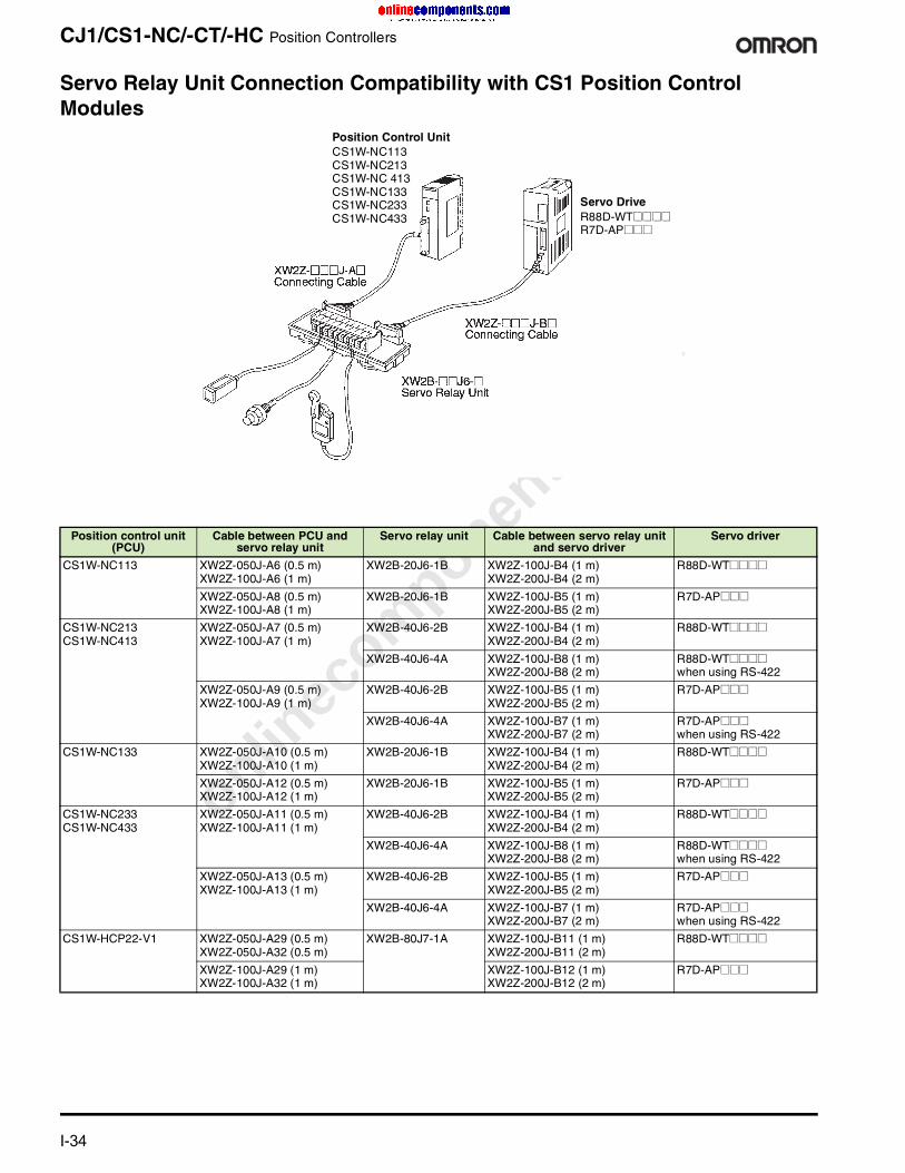
onlinec
omponen
ts.co
m
I-34 For complete specifications and additional models: U.S. www.omron.com/oei Canada www.omron.ca
CJ1/CS1-NC/-CT/-HC Position Controllers
Servo Relay Unit Connection Compatibility with CS1 Position Control Modules
Position control unit (PCU)
Cable between PCU and servo relay unit
Servo relay unit Cable between servo relay unit and servo driver
Servo driver
CS1W-NC113 XW2Z-050J-A6 (0.5 m)XW2Z-100J-A6 (1 m)
XW2B-20J6-1B XW2Z-100J-B4 (1 m)XW2Z-200J-B4 (2 m)
R88D-WT@@@@
XW2Z-050J-A8 (0.5 m)XW2Z-100J-A8 (1 m)
XW2B-20J6-1B XW2Z-100J-B5 (1 m)XW2Z-200J-B5 (2 m)
R7D-AP@@@
CS1W-NC213 CS1W-NC413
XW2Z-050J-A7 (0.5 m)XW2Z-100J-A7 (1 m)
XW2B-40J6-2B XW2Z-100J-B4 (1 m)XW2Z-200J-B4 (2 m)
R88D-WT@@@@
XW2B-40J6-4A XW2Z-100J-B8 (1 m)XW2Z-200J-B8 (2 m)
R88D-WT@@@@when using RS-422
XW2Z-050J-A9 (0.5 m)XW2Z-100J-A9 (1 m)
XW2B-40J6-2B XW2Z-100J-B5 (1 m)XW2Z-200J-B5 (2 m)
R7D-AP@@@
XW2B-40J6-4A XW2Z-100J-B7 (1 m)XW2Z-200J-B7 (2 m)
R7D-AP@@@when using RS-422
CS1W-NC133 XW2Z-050J-A10 (0.5 m)XW2Z-100J-A10 (1 m)
XW2B-20J6-1B XW2Z-100J-B4 (1 m)XW2Z-200J-B4 (2 m)
R88D-WT@@@@
XW2Z-050J-A12 (0.5 m)XW2Z-100J-A12 (1 m)
XW2B-20J6-1B XW2Z-100J-B5 (1 m)XW2Z-200J-B5 (2 m)
R7D-AP@@@
CS1W-NC233 CS1W-NC433
XW2Z-050J-A11 (0.5 m)XW2Z-100J-A11 (1 m)
XW2B-40J6-2B XW2Z-100J-B4 (1 m)XW2Z-200J-B4 (2 m)
R88D-WT@@@@
XW2B-40J6-4A XW2Z-100J-B8 (1 m)XW2Z-200J-B8 (2 m)
R88D-WT@@@@when using RS-422
XW2Z-050J-A13 (0.5 m)XW2Z-100J-A13 (1 m)
XW2B-40J6-2B XW2Z-100J-B5 (1 m)XW2Z-200J-B5 (2 m)
R7D-AP@@@
XW2B-40J6-4A XW2Z-100J-B7 (1 m)XW2Z-200J-B7 (2 m)
R7D-AP@@@when using RS-422
CS1W-HCP22-V1 XW2Z-050J-A29 (0.5 m)XW2Z-050J-A32 (0.5 m)
XW2B-80J7-1A XW2Z-100J-B11 (1 m)XW2Z-200J-B11 (2 m)
R88D-WT@@@@
XW2Z-100J-A29 (1 m)XW2Z-100J-A32 (1 m)
XW2Z-100J-B12 (1 m)XW2Z-200J-B12 (2 m)
R7D-AP@@@
Servo DriveR88D-WT@@@@R7D-AP@@@
Position Control UnitCS1W-NC113CS1W-NC213CS1W-NC 413CS1W-NC133CS1W-NC233CS1W-NC433
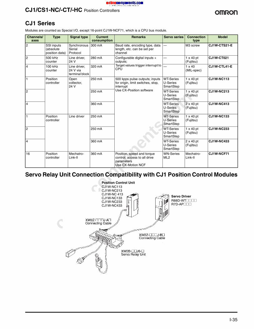
onlinec
omponen
ts.co
m
For complete specifications and additional models: U.S. www.omron.com/oei Canada www.omron.ca I-35
CJ1/CS1-NC/-CT/-HC Position Controllers
CJ1 SeriesModules are counted as Special I/O, except 16-point CJ1W-NCF71, which is a CPU bus module.
Servo Relay Unit Connection Compatibility with CJ1 Position Control Modules
Channels/ axes
Type Signal type Current consumption
Remarks Servo series Connection type
Model
2 SSI inputs (absolute position data)
Synchronous Serial Protocol
300 mA Baud rate, encoding type, data length, etc. can be set per channel
— M3 screw CJ1W-CTS21-E
2 500 kHz counter
Line driver, 24 V
280 mA Configurable digital inputs + outputs;Target values trigger interrupt to CPU
— 1 x 40 pt (Fujitsu)
CJ1W-CT021
4 100 kHz counter
Line driver, 24 V via terminal block
320 mA — 1 x 40 (MIL-spec)
CJ1W-CTL41-E
1 Position controller
Open collector, 24 V
250 mA 500 kpps pulse outputs; inputs for origin, limit switches, stop, interruptUse CX-Position software
WT-SeriesU-SeriesSmartStep
1 x 40 pt (Fujitsu)
CJ1W-NC113
2 250 mA WT-SeriesU-SeriesSmartStep
1 x 40 pt (Fujitsu)
CJ1W-NC213
4 360 mA WT-SeriesU-SeriesSmartStep
2 x 40 pt (Fujitsu)
CJ1W-NC413
1 Position controller
Line driver 250 mA WT-SeriesU-SeriesSmartStep
1 x 40 pt (Fujitsu)
CJ1W-NC133
2 250 mA WT-SeriesU-SeriesSmartStep
1 x 40 pt (Fujitsu)
CJ1W-NC233
4 360 mA WT-SeriesU-SeriesSmartStep
2 x 40 pt (Fujitsu)
CJ1W-NC433
16 Position controller
Mechatro-Link-II
360 mA Position, speed and torque control; access to all drive parametersUse CX-Motion NCF
WN-Series ML2
Mechatro-Link-II
CJ1W-NCF71
Servo DriverR88D-WT@@@@R7D-AP@@@
Position Control UnitCJ1W-NC113CJ1W-NC213CJ1W-NC 413CJ1W-NC133CJ1W-NC233CJ1W-NC433

onlinec
omponen
ts.co
m
I-36 For complete specifications and additional models: U.S. www.omron.com/oei Canada www.omron.ca
CJ1/CS1-NC/-CT/-HC Position Controllers
Software Documentation
Position control unit (PCU)
Cable between PCU and servo relay unit
Servo relay unit Cable between servo relay unit and servo driver
Servo driver
CJ1W-NC113 XW2Z-050J-A14 (0.5 m)XW2Z-100J-A14 (1 m)
XW2B-20J6-1B XW2Z-100J-B4 (1 m)XW2Z-200J-B4 (2 m)
R88D-WT@@@@
XW2Z-050J-A16 (0.5 m)XW2Z-100J-A16 (1 m)
XW2B-20J6-1B XW2Z-100J-B5 (1 m)XW2Z-200J-B5 (2 m)
R7D-AP@@@
CJ1W-NC213CJ1W-NC413
XW2Z-050J-A15 (0.5 m)XW2Z-100J-A15 (1 m)
XW2B-40J6-2B XW2Z-100J-B4 (1 m)XW2Z-200J-B4 (2 m)
R88D-WT@@@@
XW2B-40J6-4A XW2Z-100J-B8 (1 m)XW2Z-200J-B8 (2 m)
R88D-WT@@@@ when using RS-422
XW2Z-050J-A17 (0.5 m)XW2Z-100J-A17 (1 m)
XW2B-40J6-2B XW2Z-100J-B5 (1 m)XW2Z-200J-B5 (2 m)
R7D-AP@@@
XW2B-40J6-4A XW2Z-100J-B7 (1 m)XW2Z-200J-B7 (2 m)
R7D-AP@@@ when using RS-422
CJ1W-NC133 XW2Z-050J-A18 (0.5 m)XW2Z-100J-A18 (1 m)
XW2B-20J6-1B XW2Z-100J-B4 (1 m)XW2Z-200J-B4 (2 m)
R88D-WT@@@@
XW2Z-050J-A20 (0.5 m)XW2Z-100J-A20 (1 m)
XW2B-20J6-1B XW2Z-100J-B5 (1 m)XW2Z-200J-B5 (2 m)
R7D-AP@@@
CJ1W-NC233 CJ1W-NC433
XW2Z-050J-A19 (0.5 m)XW2Z-100J-A19 (1 m)
XW2B-40J6-2B XW2Z-100J-B4 (1 m)XW2Z-200J-B4 (2 m)
R88D-WT@@@@
XW2B-40J6-4A XW2Z-100J-B8 (1 m)XW2Z-200J-B8 (2 m)
R88D-WT@@@@when using RS-422
XW2Z-050J-A21 (0.5 m)XW2Z-100J-A21 (1 m)
XW2B-40J6-2B XW2Z-100J-B5 (1 m)XW2Z-200J-B5 (2 m)
R7D-AP@@@
XW2B-40J6-4A XW2Z-100J-B7 (1 m)XW2Z-200J-B7 (2 m)
R7D-AP@@@ when using RS-422
Description Specification Model
CX-Position support software Included in CX-ONE Manual W433
CX-Motion NCF support software Included in CX-ONE Manual W436

onlinec
omponen
ts.co
m
For complete specifications and additional models: U.S. www.omron.com/oei Canada www.omron.ca I-37
CJ1/CS1-MC Motion Controllers
High-Speed PLC-Based Motion ControllersMotion control modules for CJ1 and CS1 PLC series are equipped with MECHATROLINK-II interface that can control multiple drives through a single, high-speed data link. Message routing through multiple communication layers allows the attached drives to be configured from any point in the control network.
• PLC-based motion controller eliminates integration of motion controllers from other suppliers
• Complete digital control of drives via MECHATROLINK-II replaces SERCOS programming
• Controls a total of 32 axes (30 physical max.)• Simplified wiring saves design time and installation and
maintenance costs• Real multi-tasking and parallel programming• Simple to develop and modify motion programs using BASIC• Access to the complete system from one point allows quick
troubleshooting and effective time management• Linear, circular, and helical interpolation for accurate
positioning• Electronic axes synchronization produces smooth motion• Electronic cam profiles simulates popular mechanical ones
to shorten setup• Dedicated inputs/outputs on the controller• All features of the W-Series servos are available
MECHATROLINK-II is a registered trademark of Yaskawa Corporation.
MECHATROLINK-II High-Speed Motion LinkThis high-speed interface replaces the costly discrete wiring required with traditional systems. Just one MECHATROLINK-II cable eliminates the need for about 15 to 18 wires for each axis, simplifying wiring, and reducing installation costs and time. It also means that maintenance and troubleshooting are minimized. With a baud rate of up to 10 MHz, the MECHATROLINK-II link provides communication cycle times of 0.5 ms for 4 axes, to 4 ms for 30 axes, ensuring fast, precise motion control.
Ordering Information
CJ1/CS1 Motion Controllers
Motion Controllers
CJ1/CS1-MC
Type Axes Output type Rating Servo series PLC series
Current consumption
Model
Motion control module
2 axes Analog Uses G language Uses CX-Motion software
WT-SeriesU-Series
CS1 0.60 A (w/ Teaching Box: 0.80)
CS1W-MC221-V1
4 axes Analog Uses G languageUses CX-Motion software
WT-SeriesU-Series
CS1 0.70 A (w/ Teaching Box: 1.00)
CS1W-MC421-V1
30 axes MECHATRO-LINK-II
Uses CX-Motion MCH software; MECHATROLINK-II high-speed bus provides instant communications between the motional controller and Omron’s W-Series servo drivesFunctions: Electronic cam profiles and axis synchronization; Registration inputs; accesses all drive parameters; gear functions
WN-Series ML2
CS1 0.8 A, 5 VDC(counts as CPU bus unit)
CS1W-MCH71
WN-Series ML2
CJ1-H/ CJ1M
0.6 A, 5 VDC (counts as CPU bus unit)
CJ1W-MCH71

onlinec
omponen
ts.co
m
I-38 For complete specifications and additional models: U.S. www.omron.com/oei Canada www.omron.ca
CJ1/CS1-MC Motion Controllers
Servo Driver Connection Cables to Motion Control Modules
Cables Between Motion Control Unit and Servo Driver
MECHATROLINK-II Accessories and Cables
Motion Control Unit (MCU) Control axes Terminal block model
I/O Cable model (between Terminal Block and MCU)
Servo driver
CS1W-MC221 2 XW2B-20J6-6 XW2Z-100J-F1 (1 m) R88D-W
CS1W-MC421 4 XW2B-40J6-7 XW2Z-100J-F1 (1 m)
Servo driver Cable length Cable between MCU and Servo Driver
1 axis model 2-axis model
R88D-W 1 m R88A-CPW001M1 R88A-CPW001M2
2 m R88A-CPW002M1 R88A-CPW002M2
3 m R88A-CPW003M1 R88A-CPW003M2
5 m R88A-CPW005M1 R88A-CPW005M2
Motion Control Unit Description Specification Model
CJ1W-MCH71CS1W-MCH71
MECHATROLINK-II Interface Unit For W-Series servo drivers FNY-NS115
24 VDC I/O Module 64 inputs/64 outputs FNY-IO2310
Counter Module 2-channel reversible counter FNY-PL2900
Pulse Output Module For pulse positioning FNY-PL2910
Cables for W-Series with USB connectors and ring core
0.5 m FNY-W6003-A5
1 m FNY-W6003-01
3 m FNY-W6003-03
5 m FNY-W6003-05
10 m FNY-W6003-10
20 m FNY-W6003-20
30 m FNY-W6003-30
Terminating resistor for MECHATROLINK-II — FNY-W6022
Repeater for MECHATROLINK-II — FNY-REP2000
CX-Motion MCH support software Included in CX-ONE
CX-Motion support software Included in CX-ONE

onlinec
omponen
ts.co
m
For complete specifications and additional models: U.S. www.omron.com/oei Canada www.omron.ca I-39
G3JA Soft Starters
3-Phase Hybrid Soft Starters Extend Motor Life• G3JA-D Current Limit Starter for 3-phase, 6-lead motors
provides internal Star-delta control and simplifies wiring. Star-delta and protective functions are included in this single unit
• G3JA-C Soft Start, Kick Start, Current Limit Start, and Soft Stop functions for 3-phase inductive motors satisfy motor performance needs for a wide range of applications. Internal protections include protection against overload and phase loss
• Smooth motor starts and stops can reduce mechanical shock, leading to longer motor life, less frequent servicing and lower maintenance costs
• Reduced power loss through hybrid control: Power supplied through a thyristor during starting or stopping and through a bypass relay during stable operation
• Slim 45-mm body saves installation space; all models have the same shape
• Electronic Thermal Overload Relay built in protects the motor from problems such as burning due to motor overload or locking. The overload class can be set to OFF, 10, 15, or 20
• Optional Auxiliary Contact Block enhances operation monitoring by providing an output of operating status
• Meets UL508; cULus listed; complies with IEC standards, etc.
Soft Starters Ordering Information
Soft Starters
G3JA R002
Current Limit StartersSupply voltage
Main circuit operating current (A)
Lamp load (kW) HP Model
Current rating
Adjustable range
200 VAC 50/60 Hz
230 VAC 50 Hz
380/400/415 VAC 50 Hz
200 VAC 60 Hz
230 VAC 60 Hz
460 VAC 60 Hz
100 to 240 VAC, 50/60 Hz
3 1 to 3 0.2 to 0.4 0.55 1.1 0.5 0.5 0.5 to 1.5 G3JA-D403B AC100-240
9 3 to 9 0.55 to 1.5 2.2 4 0.75 to 2 0.75 to 2 1.5 to 5 G3JA-D409B AC100-240
16 5.3 to 16 1.1 to 2.2 4 7.5 1.5 to 3 1.5 to 5 5 to 10 G3JA-D416B AC100-240
20 6.7 to 20 1.5 to 3.7 5.5 7.5 2 to 5 2 to 5 5 to 10 G3JA-D420B AC100-240
25 9.2 to 27.7 2.2 to 5.5 5.5 11 3 to 7.5 3 to 7.5 7.5 to 15 G3JA-D425B AC100-240
32 10.9 to 32.9 3.7 to 7.5 7.5 15 3 to 10 5 to 10 7.5 to 20 G3JA-D432B AC100-240
51 17.3 to 51.9 5.5 to 11 15 22 5 to 15 7.5 to 15 15 to 30 G3JA-D451B AC100-240
64 21.3 to 64 5.5 to 15 18.5 30 7.5 to 20 7.5 to 20 20 to 40 G3JA-D464B AC100-240

onlinec
omponen
ts.co
m
I-40 For complete specifications and additional models: U.S. www.omron.com/oei Canada www.omron.ca
G3JA Soft Starters
Multi-function Soft Starters
Accessories
24 VAC/ VDC
3 1 to 3 0.2 to 0.4 0.55 1.1 0.5 0.5 0.5 to 1.5 G3JA-D403B AC/DC24
9 3 to 9 0.55 to 1.5 2.2 4 0.75 to 2 0.75 to 2 1.5 to 5 G3JA-D409B AC/DC24
16 5.3 to 16 1.1 to 2.2 4 7.5 1.5 to 3 1.5 to 5 5 to 10 G3JA-D416B AC/DC24
20 6.7 to 20 1.5 to 3.7 5.5 7.5 2 to 5 2 to 5 5 to 10 G3JA-D420B AC/DC24
25 9.2 to 27.7 2.2 to 5.5 5.5 11 3 to 7.5 3 to 7.5 7.5 to 15 G3JA-D425B AC/DC24
32 10.9 to 32.9 3.7 to 7.5 7.5 15 3 to 10 5 to 10 7.5 to 20 G3JA-D432B AC/DC24
51 17.3 to 51.9 5.5 to 11 15 22 5 to 15 7.5 to 15 15 to 30 G3JA-D451B AC/DC24
64 21.3 to 64 5.5 to 15 18.5 30 7.5 to 20 7.5 to 20 20 to 40 G3JA-D464B AC/DC24
Supply voltage
Main Circuit Operating Current (A)
KW at 350% of load HP at 350% of load Model
Current rating
Adjustable range
200 VAC 50/60 Hz
230 VAC 50 Hz
380/400/415 VAC 50 Hz
200 VAC60 Hz
230 VAC60 Hz
460 VAC 60 Hz
100 to 240 VAC, 50/60 Hz
3 1 to 3 0.2 to 0.4 0.55 1.1 0.5 0.5 0.5 to 1.5 G3JA-C403B AC100-240
9 3 to 9 0.55 to 1.5 2.2 4 0.75 to 2 0.75 to 2 1.5 to 5 G3JA-C409B AC100-240
16 5.3 to 16 1.1 to 2.2 4 7.5 1.5 to 3 1.5 to 5 5 to 10 G3JA-C416B AC100-240
19 6.3 to 19 1.5 to 3.7 4 7.5 1.5 to 5 2 to 5 5 to 10 G3JA-C419B AC100-240
25 8.3 to 25 2.2 to 5.5 5.5 11 3 to 7.5 3 to 7.5 7.5 to 15 G3JA-C425B AC100-240
30 10 to 30 2.2 to 5.5 7.5 15 3 to 7.5 5 to 10 7.5 to 20 G3JA-C430B AC100-240
37 12.3 to 37 3.7 to 7.5 7.5 18.5 5 to 10 5 to 10 10 to 25 G3JA-C437B AC100-240
24 VAC/ VDC
3 1 to 3 0.2 to 0.4 0.55 1.1 0.5 0.5 0.5 to 1.5 G3JA-C403B AC/DC24
9 3 to 9 0.55 to 1.5 2.2 4 0.75 to 2 0.75 to 2 1.5 to 5 G3JA-C409B AC/DC24
16 5.3 to 16 1.1 to 2.2 4 7.5 1.5 to 3 1.5 to 5 5 to 10 G3JA-C416B AC/DC24
19 6.3 to 19 1.5 to 3.7 4 7.5 1.5 to 5 2 to 5 5 to 10 G3JA-C419B AC/DC24
25 8.3 to 25 2.2 to 5.5 5.5 11 3 to 7.5 3 to 7.5 7.5 to 15 G3JA-C425B AC/DC24
30 10 to 30 2.2 to 5.5 7.5 15 3 to 7.5 5 to 10 7.5 to 20 G3JA-C430BAC/DC24
37 12.3 to 37 3.7 to 7.5 7.5 18.5 5 to 10 5 to 10 10 to 25 G3JA-C437B AC/DC24
Description Specification Model Fan Allows increased switching frequency from 4/hr to 10/hr G32J-CF64 Auxiliary contact 1 NO contact G32J-CA10 Auxiliary contacts 2 NO contacts G32J-CA20 Auxiliary contact 1 NC contact G32J-CA01 Auxiliary contacts 1 NO + 1 NC contacts G32J-CA11 Terminal block adapters Set of 2 G32J-TA10
Current Limit Starters (Continued)
Supply voltage
Main circuit operating current (A)
Lamp load (kW) HP Model
Current rating
Adjustable range
200 VAC 50/60 Hz
230 VAC 50 Hz
380/400/415 VAC 50 Hz
200 VAC 60 Hz
230 VAC 60 Hz
460 VAC 60 Hz

onlinec
omponen
ts.co
m
For complete specifications and additional models: U.S. www.omron.com/oei Canada www.omron.ca I-41
H8PS Cam Positioner
Easy-to-Use Standalone Cam Positioner Uses Encoder Input• High-speed operation at 1600 r/min and high precision
settings to 0.5°• Advanced angle compensation function compensates for
output delays• Highly visible display with reverse-lit LCD for long-distance
legibility• Fits a 1/4 DIN panel cutout• Front panel and surface/DIN rail mounting models (track
mounting adapter optional)• 8, 16 and 32 outputs models• Bank function for multi-product production (8 banks)• Use Omron absolute encoders for cam input; available with
easy-to-install connector• E6CP-AG5C-C 256 2M for 256 pulse/rev resolution • E6C3-AG5C-C 360 2M for 360 pulse/rev resolution• E6F-AG5C-C 720 2M for 720 pulse/rev resolution
• IP40 front panel rating; waterproof and protective covers available
Specifications• Supply voltage: 24 VDC• Inputs: Encoder input: Connection to a dedicated absolute
encoder• External inputs: bank inputs 1/2/4, origin input, start input
(16-/32-output models)• Control output:
• 8-output Models: 8 cam outputs, 1 RUN output, 1 pulse output
• 16-output Models 16 cam outputs, 1 RUN output, 1 pulse output
• 32-output Models: 32 cam outputs, 1 RUN output, 1 pulse output
• Output ratings:• Cam outputs, RUN output: NPN or PNP open collector,
100 mA at 30 VDC• Pulse outputs: NPN or PNP open collector, 30 mA at 30 VDC
• Dimensions: 96 H x 96 W x 65 D mm
Ordering Information
Cam Positioners
Cam Positioner
H8PS I081
Number of outputs Mounting method Dimensions L x W x H mm
Output type Bank function
Model
8 outputs Panel mounting 96 x 96 x 67.5 NPN open collector None H8PS-8BPNP open collector None H8PS-8BP
8 outputs DIN rail or surface mounting
96 x 96 x 60.6 NPN open collector None H8PS-8BFPNP open collector None H8PS-8BFP
16 outputs Panel mounting 96 x 96 x 67.5 NPN open collector None H8PS-16BPNP open collector None H8PS-16BP
16 outputs DIN rail or surface mounting
96 x 96 x 60.6 NPN open collector None H8PS-16BFPNP open collector None H8PS-16BFP
32 outputs Panel mounting 96 x 96 x 67.5 NPN open collector None H8PS-32BPNP open collector None H8PS-32BP
32 outputs DIN rail or surface mounting
96 x 96 x 60.6 NPN open collector None H8PS-32BFPNP open collector None H8PS-32BFP
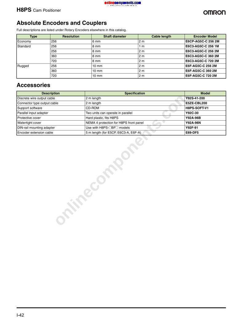
onlinec
omponen
ts.co
m
I-42 For complete specifications and additional models: U.S. www.omron.com/oei Canada www.omron.ca
H8PS Cam Positioner
Absolute Encoders and CouplersFull descriptions are listed under Rotary Encoders elsewhere in this catalog.
Accessories
Type Resolution Shaft diameter Cable length Encoder Model
Economy 256 6 mm 2 m E6CP-AG5C-C 256 2M
Standard 256 8 mm 1 m E6C3-AG5C-C 256 1M
256 8 mm 2 m E6C3-AG5C-C 256 2M
360 8 mm 2 m E6C3-AG5C-C 360 2M
720 8 mm 2 m E6C3-AG5C-C 720 2M
Rugged 256 10 mm 2 m E6F-AG5C-C 256 2M
360 10 mm 2 m E6F-AG5C-C 360 2M
720 10 mm 2 m E6F-AG5C-C 720 2M
Description Specification Model
Discrete wire output cable 2 m length Y92S-41-200
Connector type output cable 2 m length E5ZE-CBL200
Support software CD-ROM H8PS-SOFT-V1
Parallel input adapter Two units can operate in parallel Y92C-30
Protective cover Hard plastic, fits H8PS Y92A-96B
Watertight cover NEMA 4 protection for H8PS front panel Y92A-96N
DIN-rail mounting adapter Use with H8PS-@BF@ models Y92F-91
Encoder extension cable 5 m length (for E5CP, E6C3-A, E6F-A) E69-DF5
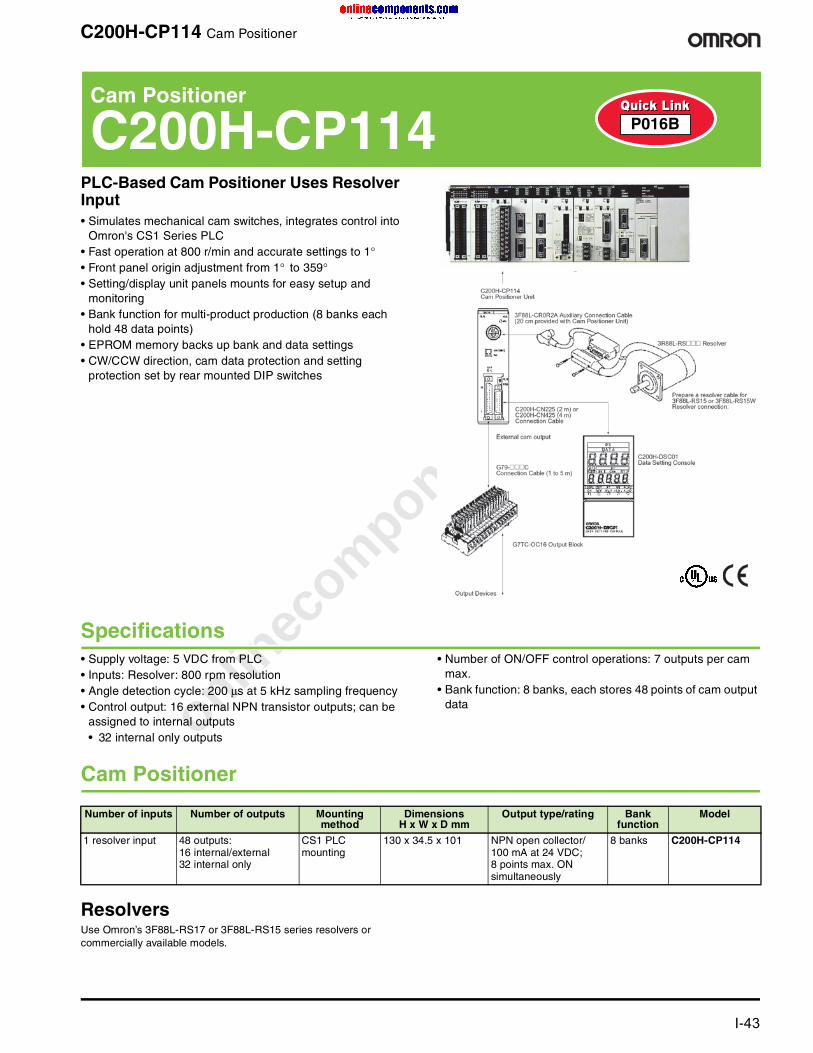
onlinec
omponen
ts.co
m
For complete specifications and additional models: U.S. www.omron.com/oei Canada www.omron.ca I-43
C200H-CP114 Cam Positioner
PLC-Based Cam Positioner Uses Resolver Input• Simulates mechanical cam switches, integrates control into
Omron's CS1 Series PLC• Fast operation at 800 r/min and accurate settings to 1°• Front panel origin adjustment from 1° to 359°• Setting/display unit panels mounts for easy setup and
monitoring• Bank function for multi-product production (8 banks each
hold 48 data points)• EPROM memory backs up bank and data settings• CW/CCW direction, cam data protection and setting
protection set by rear mounted DIP switches
Specifications• Supply voltage: 5 VDC from PLC• Inputs: Resolver: 800 rpm resolution• Angle detection cycle: 200 µs at 5 kHz sampling frequency• Control output: 16 external NPN transistor outputs; can be
assigned to internal outputs• 32 internal only outputs
• Number of ON/OFF control operations: 7 outputs per cam max.
• Bank function: 8 banks, each stores 48 points of cam output data
Cam Positioner
ResolversUse Omron’s 3F88L-RS17 or 3F88L-RS15 series resolvers or commercially available models.
Cam Positioner
C200H-CP114 P016B
Number of inputs Number of outputs Mounting method
DimensionsH x W x D mm
Output type/rating Bank function
Model
1 resolver input 48 outputs:16 internal/external32 internal only
CS1 PLC mounting
130 x 34.5 x 101 NPN open collector/ 100 mA at 24 VDC; 8 points max. ON simultaneously
8 banks C200H-CP114

onlinec
omponen
ts.co
m
I-44 For complete specifications and additional models: U.S. www.omron.com/oei Canada www.omron.ca
E6C3-A Rotary Encoders—Absolute
Water Resistant Encoder for Tough Environments• IP65f drip-proof, oil-proof construction with sealed bearing• 8 mm stainless steel shaft provides superior shaft loading
performance: Radial: 8 kg-f; Axial: 5.1 kg-f• NPN, or PNP open collector or voltage outputs• Optimum angle control when combined with cam positioner
(stand-alone H8PS or PLC-based) or encoder-input PLC position control modules
• Response frequency: 20 kHz max., 5,000 rpm max.• Pre-wired with 1 meter cable; 2 meter cable available,
connector version available for direct connection to an H8PS Cam Positioning unit
Absolute Rotary Encoders When ordering, specify the resolution in addition to the model number (example: E6C3-AG5C 360P/R 1M).
Rotary Encoders—Absolute
E6C3-A P060A
Size Shaft Supply voltage
Output configuration
Output code
Resolution (pulses/rotation)
Connection method Model
50 dia. x 43 D mm
8 dia. x 15 L mm, stainless steel
12 to 24 VDC NPN open-collector output
Gray 256, 360, 720 2 m connector for H8PS Cam Positioner
E6C3-AG5C-C
256, 360, 720, 1,024 Pre-wired, 1 m cable E6C3-AG5C
Binary 32, 40 E6C3-AN5C
BCD 6, 8, 12 E6C3-AB5C
PNP open-collector output
Gray 256, 360, 720, 1,024 E6C3-AG5B
Binary 32, 40 E6C3-AN5B
BCD 6, 8, 12 E6C3-AB5B
5 VDC Voltage output Binary 256 E6C3-AN1E
12 VDC E6C3-AN2E

onlinec
omponen
ts.co
m
For complete specifications and additional models: U.S. www.omron.com/oei Canada www.omron.ca I-45
E6CP Rotary Encoders—Absolute
Low-Cost Absolute Encoder, 50 mm Diameter• High-precision detection of automatic machine timing, also
ideal for robot limit signals• Absolute encoder performance at the cost of an incremental
encoder• Gray code output eliminates reading mistakes• Lightweight, plastic body construction, IP50 enclosure rating• Shaft loading: Radial: 3 kg-f; Axial: 2 kg-f• Open collector output• Response frequency: 5 kHz max., 1,000 rpm max.• Pre-wired with 2-meter cable, connector version available for
direct connection to an H8PS Cam Positioning unit
Absolute Rotary Encoders
Rotary Encoders—Absolute
E6CP F029
Size Shaft Power supply voltage
Output configuration
Output code
Resolution (pulses/ rotation)
Connection method Model
50 dia. x 55 D mm
6 dia. x 10 L mm
5 to 12 VDC Open-collector output
Gray 256 (8-bit) Pre-wired, 2 m cable E6CP-AG3C
12 to 24 VDC E6CP-AG5C
2 m cable with connector for H8PS Cam Positioner
E6CP-AG5C-C
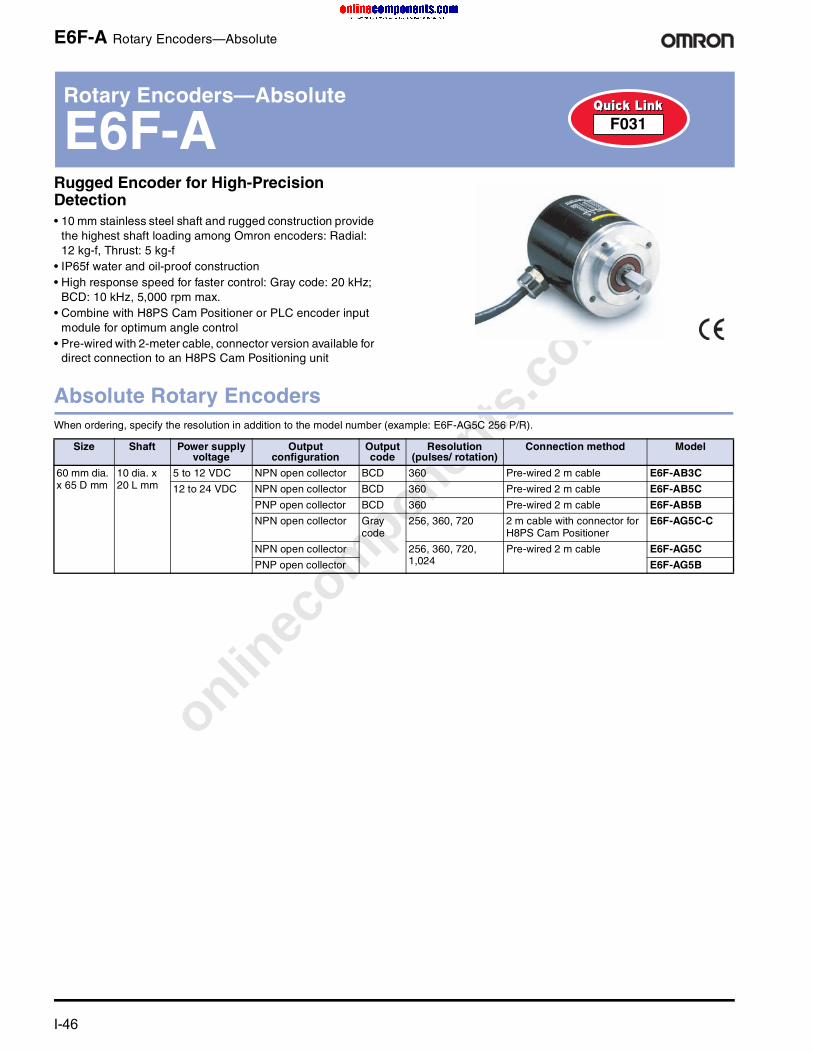
onlinec
omponen
ts.co
m
I-46 For complete specifications and additional models: U.S. www.omron.com/oei Canada www.omron.ca
E6F-A Rotary Encoders—Absolute
Rugged Encoder for High-Precision Detection• 10 mm stainless steel shaft and rugged construction provide
the highest shaft loading among Omron encoders: Radial: 12 kg-f, Thrust: 5 kg-f
• IP65f water and oil-proof construction• High response speed for faster control: Gray code: 20 kHz;
BCD: 10 kHz, 5,000 rpm max.• Combine with H8PS Cam Positioner or PLC encoder input
module for optimum angle control• Pre-wired with 2-meter cable, connector version available for
direct connection to an H8PS Cam Positioning unit
Absolute Rotary Encoders When ordering, specify the resolution in addition to the model number (example: E6F-AG5C 256 P/R).
Rotary Encoders—Absolute
E6F-A F031
Size Shaft Power supply voltage
Output configuration
Output code
Resolution (pulses/ rotation)
Connection method Model
60 mm dia. x 65 D mm
10 dia. x 20 L mm
5 to 12 VDC NPN open collector BCD 360 Pre-wired 2 m cable E6F-AB3C
12 to 24 VDC NPN open collector BCD 360 Pre-wired 2 m cable E6F-AB5C
PNP open collector BCD 360 Pre-wired 2 m cable E6F-AB5B
NPN open collector Gray code
256, 360, 720 2 m cable with connector for H8PS Cam Positioner
E6F-AG5C-C
NPN open collector 256, 360, 720, 1,024
Pre-wired 2 m cable E6F-AG5C
PNP open collector E6F-AG5B

onlinec
omponen
ts.co
m
For complete specifications and additional models: U.S. www.omron.com/oei Canada www.omron.ca I-47
E6A2-C Rotary Encoders—Incremental
Miniature Positioning Solution for Tight Spaces• High response frequency and noise immunity make
encoders ideal for factory automation applications with 10 to 500 pulses/revolution
• Space saving enclosure: 25 mm dia.• 4 mm shaft with load rating of: Radial: 1 kg-f; Axial: 0.5 kg-f• Open collector output, other output types available• Output phases: A/A, B and A, B, Z (reversible) are available• Response frequency: 20 kHz max., 5,000 rpm max. • Enclosure rating: IP50• Pre-wired with 0.5 meter cable
Incremental Rotary Encoders
Rotary Encoders—Incremental
E6A2-C F020
Size Shaft Supply voltage
Output configuration Resolution (pulses/ revolution)
Model
25 dia. x 31 D mm 4 dia. x 10 L mm 12 to 24 VDC NPN open collector, 30 mA max. 100 E6A2-CW5C 100P/R 05M
200 E6A2-CW5C 200P/R 05M

onlinec
omponen
ts.co
m
I-48 For complete specifications and additional models: U.S. www.omron.com/oei Canada www.omron.ca
E6B2-C Rotary Encoders—Incremental
General-Purpose Compact Encoders• High resolution models (up to 2000 pulses per revolution
available) substantially improve measuring accuracy• Rugged construction: 6 mm shaft with load rating of: Radial:
3 kg-f; Axial: 2 kg-f • Output phases: A, B, Z (reversible)• Response frequency: up to 100 kHz max., 6,000 rpm max.• Protected against short-circuit and reversed connections for
highly reliable operation• Available with NPN and PNP open collector, voltage and line
driver outputs• Enclosure rating: IP50• Pre-wired with 0.5- or 2-meter cables
Incremental Rotary Encoders
Rotary Encoders—Incremental
E6B2-C F022
Size Shaft Supply voltage
Output configuration Resolution (pulses/ revolution)
Cablelength
Model
40 mm dia. x 44 D mm
6 dia. x 15 L mm 12 to 24 VDC
NPN open collector, 35 mA max.
100 2 m E6B2-CWZ6C 100P/R 2M
200 2 m E6B2-CWZ6C 200P/R 2M
360 0.5 m E6B2-CWZ6C 360P/R 05M
360 2 m E6B2-CWZ6C 360P/R 2M
500 2 m E6B2-CWZ6C 500P/R 2M
600 2 m E6B2-CWZ6C 600P/R 2M
1000 0.5 m E6B2-CWZ6C 1000P/R 05M
1000 2 m E6B2-CWZ6C 1000P/R 2M
5 VDC Line driver: High: -20 mA or 2.5 V min.Low: +20 mA or 0.5 V max.
1000 0.5 m E6B2-CWZ1X 1000P/R 05M
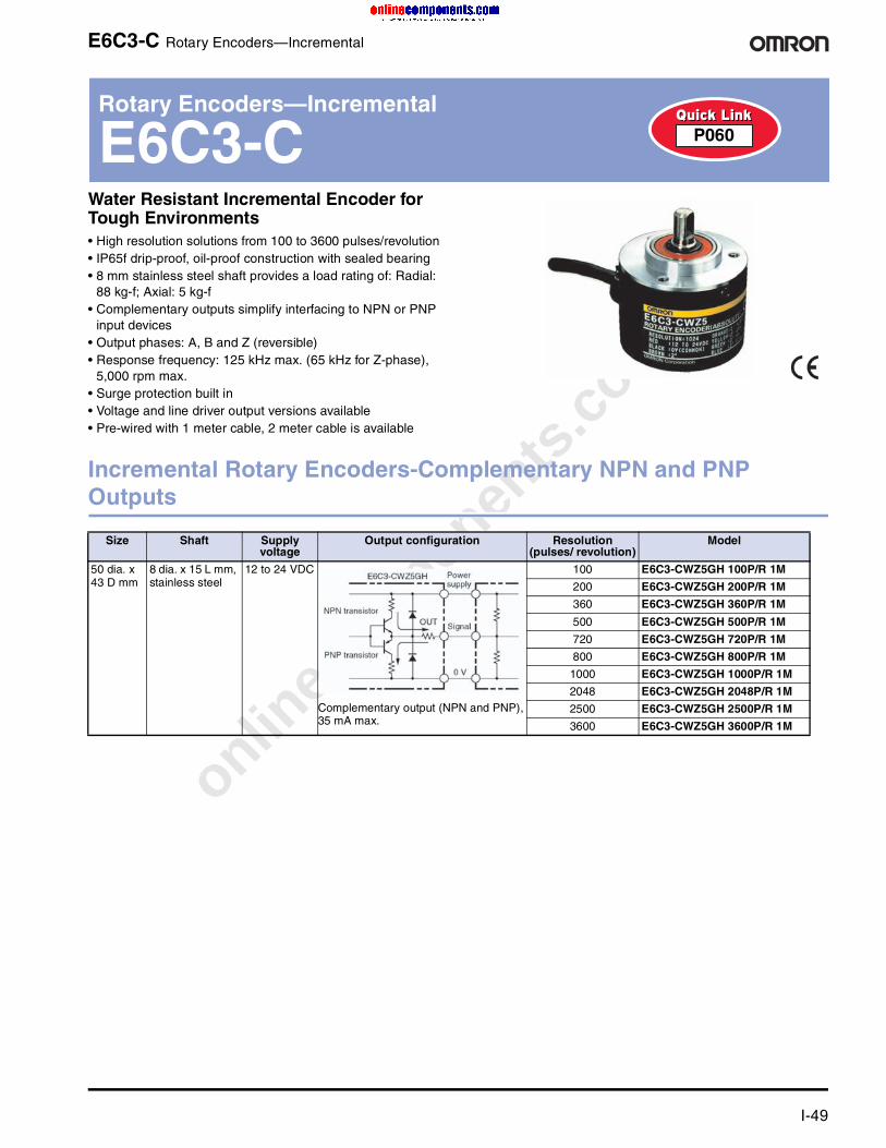
onlinec
omponen
ts.co
m
For complete specifications and additional models: U.S. www.omron.com/oei Canada www.omron.ca I-49
E6C3-C Rotary Encoders—Incremental
Water Resistant Incremental Encoder for Tough Environments• High resolution solutions from 100 to 3600 pulses/revolution• IP65f drip-proof, oil-proof construction with sealed bearing• 8 mm stainless steel shaft provides a load rating of: Radial:
88 kg-f; Axial: 5 kg-f• Complementary outputs simplify interfacing to NPN or PNP
input devices• Output phases: A, B and Z (reversible)• Response frequency: 125 kHz max. (65 kHz for Z-phase),
5,000 rpm max.• Surge protection built in• Voltage and line driver output versions available• Pre-wired with 1 meter cable, 2 meter cable is available
Incremental Rotary Encoders-Complementary NPN and PNP Outputs
Rotary Encoders—Incremental
E6C3-C P060
Size Shaft Supply voltage
Output configuration Resolution (pulses/ revolution)
Model
50 dia. x 43 D mm
8 dia. x 15 L mm, stainless steel
12 to 24 VDC
Complementary output (NPN and PNP), 35 mA max.
100 E6C3-CWZ5GH 100P/R 1M
200 E6C3-CWZ5GH 200P/R 1M
360 E6C3-CWZ5GH 360P/R 1M
500 E6C3-CWZ5GH 500P/R 1M
720 E6C3-CWZ5GH 720P/R 1M
800 E6C3-CWZ5GH 800P/R 1M
1000 E6C3-CWZ5GH 1000P/R 1M
2048 E6C3-CWZ5GH 2048P/R 1M
2500 E6C3-CWZ5GH 2500P/R 1M
3600 E6C3-CWZ5GH 3600P/R 1M

onlinec
omponen
ts.co
m
I-50 For complete specifications and additional models: U.S. www.omron.com/oei Canada www.omron.ca
E6D Rotary Encoders—Incremental
Rugged, High-Resolution Encoder• Resolution as high as 6,000 pulses/revolution in a rugged
construction• Outputs: A, B (reversible) and Z (zero)• 55 mm diameter housing• Superb reliability and accuracy: phase error as small as 1/4T
±0.07T• High response frequency of 200 kHz, 12,000 rpm max.• 6 mm shaft with load rating of: radial: 5 kg-f; axial: 3 kg-f
Incremental Rotary EncodersAdd resolution (pulses/revolution) before P/R in the model number.
Rugged Encoder with Strongest Shaft• 10 mm stainless steel shaft and rugged construction
provides the highest shaft loading among Omron encoders: Radial: 12 kg-f, Thrust: 5 kg-f
• IP65f water- and oil-proof construction• 60 mm diameter housing • Complementary output for longer cable length extension• High response frequency of 83 kHz, 5,000 rpm max.• Output load short-circuit protection to reduce risks from
incorrect wiring• Pre-wired 2 meter cable
Incremental Rotary EncodersAdd resolution (pulses/revolution) before P/R in the model number.
Rotary Encoders—Incremental
E6D F030
Size Shaft Supply voltage
Output configuration
Resolution (pulses/ revolution)
Cable length
Model
40 mm dia. x 44 D mm
6 dia. x 15 L mm 12 VDC NPN open collector, 35 mA max.
720, 800, 1000, 1024, 1200, 1500, 1800, 2000, 2048, 2500, 3000, 3200, 3600, 4096, 5000, 6000
0.5 m E6D-CWZ2C@@@@P/R 05M
5 VDC 0.5 m E6D-CWZ1E@@@@P/R 05M
Rotary Encoders—Incremental
E6F-C Q037
Size Shaft Supply voltage
Output configuration
Resolution (pulses/ revolution)
Cable length
Model
60 mm dia. x 65 D mm
10 dia. x 20 L mm 12 to 24 VDC
Complementary NPN and PNP, ±30 mA
100, 200, 360, 500, 600, 1000
2 m E6F-CWZ5GP/R 2M

onlinec
omponen
ts.co
m
Terms and Conditions of Sale1. Offer; Acceptance. These terms and conditions (these "Terms") are deemed
part of all quotes, agreements, purchase orders, acknowledgments, price lists,catalogs, manuals, brochures and other documents, whether electronic or inwriting, relating to the sale of products or services (collectively, the "Products")by Omron Electronics LLC and its subsidiary companies (“Omron”). Omronobjects to any terms or conditions proposed in Buyer’s purchase order or otherdocuments which are inconsistent with, or in addition to, these Terms.
2. Prices; Payment Terms. All prices stated are current, subject to change with-out notice by Omron. Omron reserves the right to increase or decrease priceson any unshipped portions of outstanding orders. Payments for Products aredue net 30 days unless otherwise stated in the invoice.
3. Discounts. Cash discounts, if any, will apply only on the net amount of invoicessent to Buyer after deducting transportation charges, taxes and duties, and willbe allowed only if (i) the invoice is paid according to Omron’s payment termsand (ii) Buyer has no past due amounts.
4. Interest. Omron, at its option, may charge Buyer 1-1/2% interest per month orthe maximum legal rate, whichever is less, on any balance not paid within thestated terms.
5. Orders. Omron will accept no order less than $200 net billing. 6. Governmental Approvals. Buyer shall be responsible for, and shall bear all
costs involved in, obtaining any government approvals required for the impor-tation or sale of the Products.
7. Taxes. All taxes, duties and other governmental charges (other than generalreal property and income taxes), including any interest or penalties thereon,imposed directly or indirectly on Omron or required to be collected directly orindirectly by Omron for the manufacture, production, sale, delivery, importa-tion, consumption or use of the Products sold hereunder (including customsduties and sales, excise, use, turnover and license taxes) shall be charged toand remitted by Buyer to Omron.
8. Financial. If the financial position of Buyer at any time becomes unsatisfactoryto Omron, Omron reserves the right to stop shipments or require satisfactorysecurity or payment in advance. If Buyer fails to make payment or otherwisecomply with these Terms or any related agreement, Omron may (without liabil-ity and in addition to other remedies) cancel any unshipped portion of Prod-ucts sold hereunder and stop any Products in transit until Buyer pays allamounts, including amounts payable hereunder, whether or not then due,which are owing to it by Buyer. Buyer shall in any event remain liable for allunpaid accounts.
9. Cancellation; Etc. Orders are not subject to rescheduling or cancellationunless Buyer indemnifies Omron against all related costs or expenses.
10. Force Majeure. Omron shall not be liable for any delay or failure in deliveryresulting from causes beyond its control, including earthquakes, fires, floods,strikes or other labor disputes, shortage of labor or materials, accidents tomachinery, acts of sabotage, riots, delay in or lack of transportation or therequirements of any government authority.
11. Shipping; Delivery. Unless otherwise expressly agreed in writing by Omron:a. Shipments shall be by a carrier selected by Omron; Omron will not drop ship
except in “break down” situations.b. Such carrier shall act as the agent of Buyer and delivery to such carrier shall
constitute delivery to Buyer;c. All sales and shipments of Products shall be FOB shipping point (unless oth-
erwise stated in writing by Omron), at which point title and risk of loss shallpass from Omron to Buyer; provided that Omron shall retain a security inter-est in the Products until the full purchase price is paid;
d. Delivery and shipping dates are estimates only; ande. Omron will package Products as it deems proper for protection against nor-
mal handling and extra charges apply to special conditions.12. Claims. Any claim by Buyer against Omron for shortage or damage to the
Products occurring before delivery to the carrier must be presented in writingto Omron within 30 days of receipt of shipment and include the original trans-portation bill signed by the carrier noting that the carrier received the Productsfrom Omron in the condition claimed.
13. Warranties. (a) Exclusive Warranty. Omron’s exclusive warranty is that theProducts will be free from defects in materials and workmanship for a period oftwelve months from the date of sale by Omron (or such other period expressedin writing by Omron). Omron disclaims all other warranties, express or implied.(b) Limitations. OMRON MAKES NO WARRANTY OR REPRESENTATION,EXPRESS OR IMPLIED, ABOUT NON-INFRINGEMENT, MERCHANTABIL-
ITY OR FITNESS FOR A PARTICULAR PURPOSE OF THE PRODUCTS.BUYER ACKNOWLEDGES THAT IT ALONE HAS DETERMINED THAT THEPRODUCTS WILL SUITABLY MEET THE REQUIREMENTS OF THEIRINTENDED USE. Omron further disclaims all warranties and responsibility ofany type for claims or expenses based on infringement by the Products or oth-erwise of any intellectual property right. (c) Buyer Remedy. Omron’s sole obli-gation hereunder shall be, at Omron’s election, to (i) replace (in the formoriginally shipped with Buyer responsible for labor charges for removal orreplacement thereof) the non-complying Product, (ii) repair the non-complyingProduct, or (iii) repay or credit Buyer an amount equal to the purchase price ofthe non-complying Product; provided that in no event shall Omron be responsi-ble for warranty, repair, indemnity or any other claims or expenses regardingthe Products unless Omron’s analysis confirms that the Products were prop-erly handled, stored, installed and maintained and not subject to contamina-tion, abuse, misuse or inappropriate modification. Return of any Products byBuyer must be approved in writing by Omron before shipment. Omron Compa-nies shall not be liable for the suitability or unsuitability or the results from theuse of Products in combination with any electrical or electronic components,circuits, system assemblies or any other materials or substances or environ-ments. Any advice, recommendations or information given orally or in writing,are not to be construed as an amendment or addition to the above warranty.See http://www.omron247.com or contact your Omron representative for pub-lished information.
14. Limitation on Liability; Etc. OMRON COMPANIES SHALL NOT BE LIABLEFOR SPECIAL, INDIRECT, INCIDENTAL, OR CONSEQUENTIAL DAMAGES,LOSS OF PROFITS OR PRODUCTION OR COMMERCIAL LOSS IN ANYWAY CONNECTED WITH THE PRODUCTS, WHETHER SUCH CLAIM ISBASED IN CONTRACT, WARRANTY, NEGLIGENCE OR STRICT LIABILITY.Further, in no event shall liability of Omron Companies exceed the individualprice of the Product on which liability is asserted.
15. Indemnities. Buyer shall indemnify and hold harmless Omron Companies andtheir employees from and against all liabilities, losses, claims, costs andexpenses (including attorney's fees and expenses) related to any claim, inves-tigation, litigation or proceeding (whether or not Omron is a party) which arisesor is alleged to arise from Buyer's acts or omissions under these Terms or inany way with respect to the Products. Without limiting the foregoing, Buyer (atits own expense) shall indemnify and hold harmless Omron and defend or set-tle any action brought against such Companies to the extent based on a claimthat any Product made to Buyer specifications infringed intellectual propertyrights of another party.
16. Property; Confidentiality. Any intellectual property in the Products is the exclu-sive property of Omron Companies and Buyer shall not attempt to duplicate itin any way without the written permission of Omron. Notwithstanding anycharges to Buyer for engineering or tooling, all engineering and tooling shallremain the exclusive property of Omron. All information and materials suppliedby Omron to Buyer relating to the Products are confidential and proprietary,and Buyer shall limit distribution thereof to its trusted employees and strictlyprevent disclosure to any third party.
17. Export Controls. Buyer shall comply with all applicable laws, regulations andlicenses regarding (i) export of products or information; (iii) sale of products to“forbidden” or other proscribed persons; and (ii) disclosure to non-citizens ofregulated technology or information.
18. Miscellaneous. (a) Waiver. No failure or delay by Omron in exercising any rightand no course of dealing between Buyer and Omron shall operate as a waiverof rights by Omron. (b) Assignment. Buyer may not assign its rights hereunderwithout Omron's written consent. (c) Law. These Terms are governed by thelaw of the jurisdiction of the home office of the Omron company from whichBuyer is purchasing the Products (without regard to conflict of law princi-ples). (d) Amendment. These Terms constitute the entire agreement betweenBuyer and Omron relating to the Products, and no provision may be changedor waived unless in writing signed by the parties. (e) Severability. If any provi-sion hereof is rendered ineffective or invalid, such provision shall not invalidateany other provision. (f) Setoff. Buyer shall have no right to set off any amountsagainst the amount owing in respect of this invoice. (g) Definitions. As usedherein, “including” means “including without limitation”; and “Omron Compa-nies” (or similar words) mean Omron Corporation and any direct or indirectsubsidiary or affiliate thereof.
Certain Precautions on Specifications and Use1. Suitability of Use. Omron Companies shall not be responsible for conformity
with any standards, codes or regulations which apply to the combination of theProduct in the Buyer’s application or use of the Product. At Buyer’s request,Omron will provide applicable third party certification documents identifyingratings and limitations of use which apply to the Product. This information byitself is not sufficient for a complete determination of the suitability of the Prod-uct in combination with the end product, machine, system, or other applicationor use. Buyer shall be solely responsible for determining appropriateness ofthe particular Product with respect to Buyer’s application, product or system.Buyer shall take application responsibility in all cases but the following is anon-exhaustive list of applications for which particular attention must be given:(i) Outdoor use, uses involving potential chemical contamination or electricalinterference, or conditions or uses not described in this document.(ii) Use in consumer products or any use in significant quantities. (iii) Energy control systems, combustion systems, railroad systems, aviationsystems, medical equipment, amusement machines, vehicles, safety equip-ment, and installations subject to separate industry or government regulations. (iv) Systems, machines and equipment that could present a risk to life or prop-erty. Please know and observe all prohibitions of use applicable to this Prod-uct. NEVER USE THE PRODUCT FOR AN APPLICATION INVOLVING SERIOUSRISK TO LIFE OR PROPERTY OR IN LARGE QUANTITIES WITHOUTENSURING THAT THE SYSTEM AS A WHOLE HAS BEEN DESIGNED TO
ADDRESS THE RISKS, AND THAT THE OMRON’S PRODUCT IS PROP-ERLY RATED AND INSTALLED FOR THE INTENDED USE WITHIN THEOVERALL EQUIPMENT OR SYSTEM.
2. Programmable Products. Omron Companies shall not be responsible for theuser’s programming of a programmable Product, or any consequence thereof.
3. Performance Data. Data presented in Omron Company websites, catalogsand other materials is provided as a guide for the user in determining suitabil-ity and does not constitute a warranty. It may represent the result of Omron’stest conditions, and the user must correlate it to actual application require-ments. Actual performance is subject to the Omron’s Warranty and Limitationsof Liability.
4. Change in Specifications. Product specifications and accessories may bechanged at any time based on improvements and other reasons. It is our prac-tice to change part numbers when published ratings or features are changed,or when significant construction changes are made. However, some specifica-tions of the Product may be changed without any notice. When in doubt, spe-cial part numbers may be assigned to fix or establish key specifications foryour application. Please consult with your Omron’s representative at any timeto confirm actual specifications of purchased Product.
5. Errors and Omissions. Information presented by Omron Companies has beenchecked and is believed to be accurate; however, no responsibility is assumedfor clerical, typographical or proofreading errors or omissions.
onlinec
omponen
ts.co
m
OMRON ON-LINEGlobal –www.omron.com
USA – www.omron247.com
Canada –www.omron.ca
Brazil –www.omron.com.br
Cat. No. MOTIONCONTROLCATALOG2006 Printed in USA
MEXICO SALES OFFICESMexico, D.F. (52) 555 660 31 44Ciudad Juárez (52) 656 623 70 83Monterrey, N.L. (52) 818 377 42 81Mexicali, B.C. (52) 686 838 01 15
BRAZIL SALES OFFICESSao Paulo (55) 11 2101 6300
ARGENTINA SALES OFFICESCono Sur (54) 11 4787 1129
CHILE SALES OFFICESSantiago (56) 2206 4592
OTHER LATIN AMERICAN [email protected]
OMRON ELECTRONICS LLC1 Commerce DriveSchaumburg, IL 60173Tel: 847.843.7900
For U.S. technical support or other inquiries: 800.556.6766
OMRON CANADA, INC.885 Milner AvenueToronto, Ontario M1B 5V8Tel: 416.286.6465
Specifications subject to change without notice
Complete “Terms and Conditions of Sale” for product purchase and use are on Omron’s websiteat www.omron.com/oei – under the “About Us” tab, in the Legal Matters section.
ALL DIMENSIONS SHOWN ARE IN MILLIMETERS.To convert millimeters into inches, multiply by 0.03937. To convert grams into ounces, multiply by 0.03527.