monolith multiphase 2012
DESCRIPTION
Monoliths as G-L-S reactorsTRANSCRIPT
7/21/2019 Monolith Multiphase 2012
http://slidepdf.com/reader/full/monolith-multiphase-2012 1/52
Monolith reactors - 1
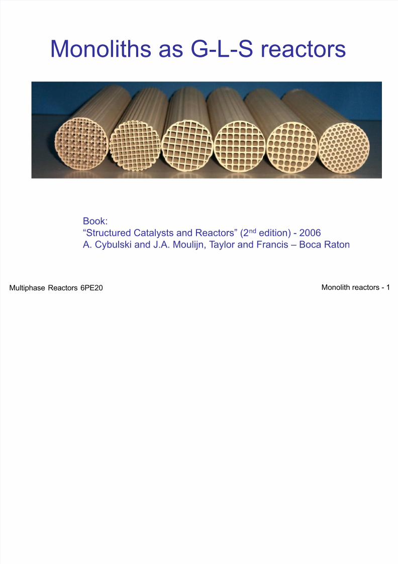
Monoliths as G-L-S reactors
Book:“Structured Catalysts and Reactors” (2nd edition) - 2006 A. Cybulski and J.A. Moulijn, Taylor and Francis – Boca Raton
Multiphase Reactors 6PE20
7/21/2019 Monolith Multiphase 2012
http://slidepdf.com/reader/full/monolith-multiphase-2012 2/52
Monolith reactors - 2
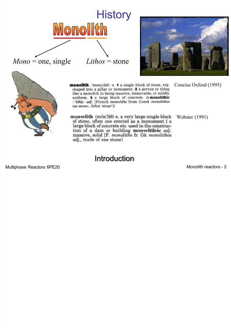
History
Mono = one, single Lithos = stone
Concise Oxford (1995)
Webster (1991)
IntroductionMultiphase Reactors 6PE20
7/21/2019 Monolith Multiphase 2012
http://slidepdf.com/reader/full/monolith-multiphase-2012 3/52
Monolith reactors - 3
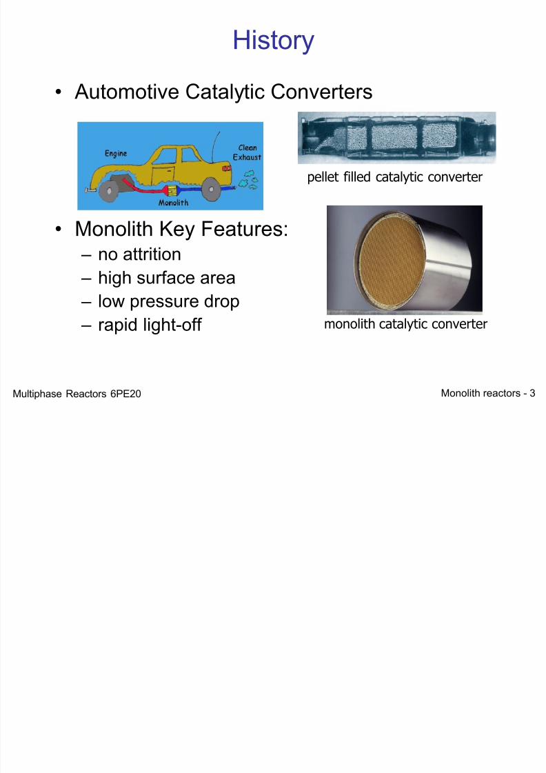
History
• Automotive Catalytic Converters
• Monolith Key Features: – no attrition
– high surface area – low pressure drop – rapid light-off
pellet filled catalytic converter
monolith catalytic converter
Multiphase Reactors 6PE20
7/21/2019 Monolith Multiphase 2012
http://slidepdf.com/reader/full/monolith-multiphase-2012 4/52
Monolith reactors - 4
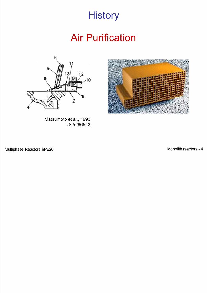
History
Matsumoto et al., 1993US 5266543
Air Purification
Multiphase Reactors 6PE20
7/21/2019 Monolith Multiphase 2012
http://slidepdf.com/reader/full/monolith-multiphase-2012 5/52
Monolith reactors - 5
Structured ReactorsDriving forces
• Pressure drop
• Mass transfer
• Counter Current operation• Surface area
• Catalyst Efficiency
• Fluid distribution• Catalyst Separation
Multiphase Reactors 6PE20
7/21/2019 Monolith Multiphase 2012
http://slidepdf.com/reader/full/monolith-multiphase-2012 6/52
Monolith reactors - 6
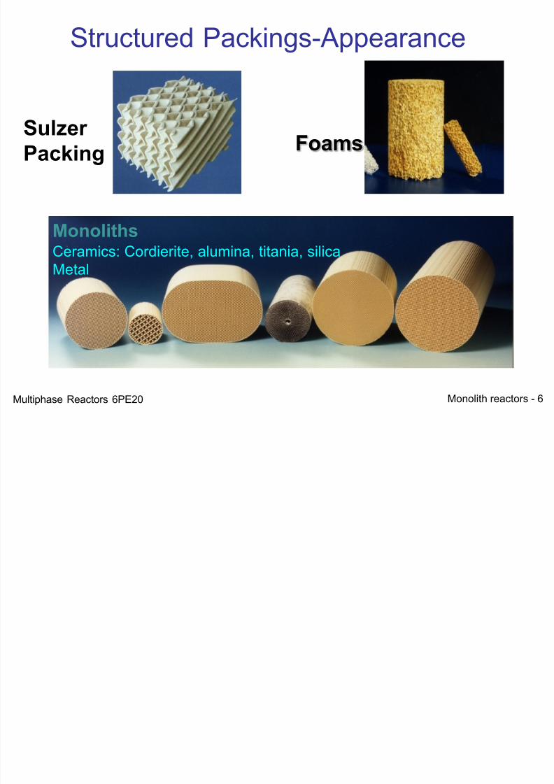
Ceramics: Cordierite, alumina, titania, silicaMetal
Sulzer
Packing Foams
Structured Packings-Appearance
Monoliths
Multiphase Reactors 6PE20
7/21/2019 Monolith Multiphase 2012
http://slidepdf.com/reader/full/monolith-multiphase-2012 7/52Monolith reactors - 7
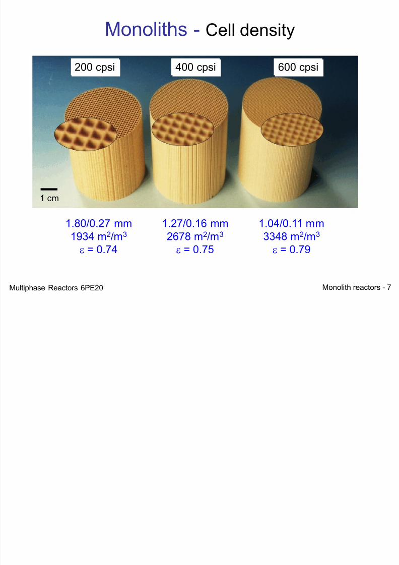
200 cpsi 400 cpsi 600 cpsi
1.80/0.27 mm1934 m2/m3 = 0.74
1.27/0.16 mm2678 m2/m3 = 0.75
1.04/0.11 mm3348 m2/m3 = 0.79
Monoliths - Cell density
1 cm
Multiphase Reactors 6PE20
7/21/2019 Monolith Multiphase 2012
http://slidepdf.com/reader/full/monolith-multiphase-2012 8/52Monolith reactors - 8
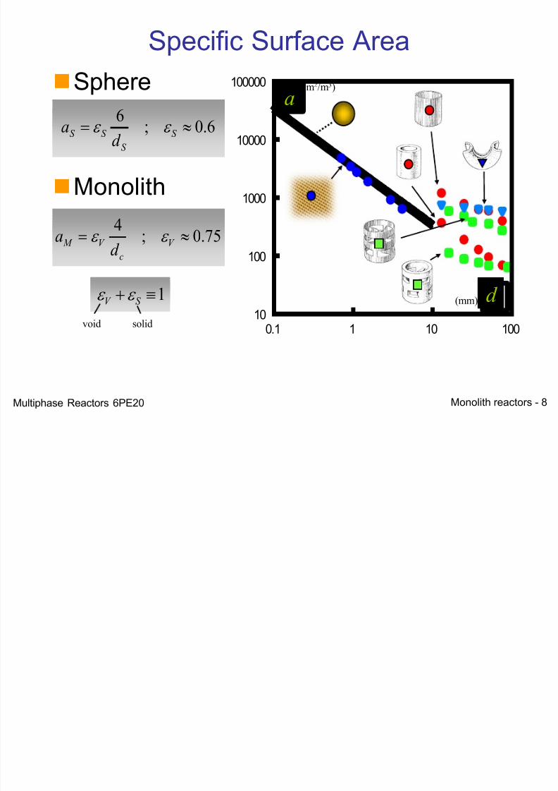
Sphere
Monolith
0.1 1 10 10010
100
1000
10000
100000
d
a
(mm)
(m2/m3)
75.0;4
V
c
V M d
a
6.0;6
S
S
S S d
a
1 S V
void solid
a
d
Specific Surface Area
Multiphase Reactors 6PE20
7/21/2019 Monolith Multiphase 2012
http://slidepdf.com/reader/full/monolith-multiphase-2012 9/52Monolith reactors - 9
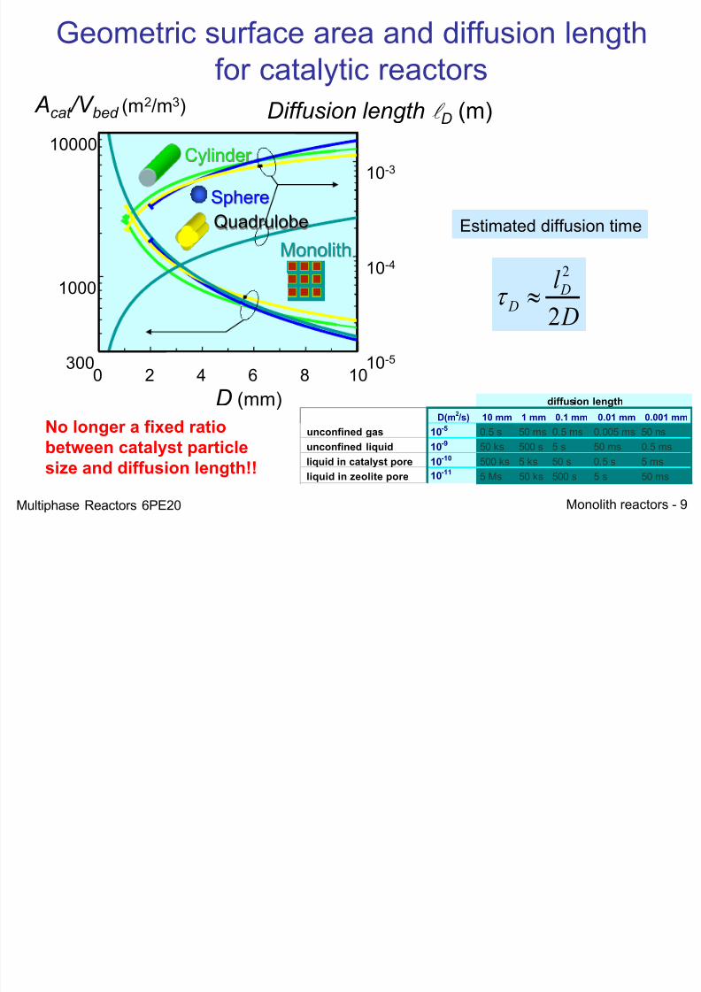
0 2 4 6 8 10 300
1000
10000
10-5
10-4
10-3 Cylinder
Quadrulobe
Monolith
Sphere
Acat /V bed (m2/m3)
D (mm)
Diffusion length
D (m)
D(m2 /s) 10 mm 1 mm 0.1 mm 0.01 mm 0.001 mm
unconfined gas 10-50.5 s 50 ms 0.5 ms 0.005 ms 50 ns
unconfined liquid 10-950 ks 500 s 5 s 50 ms 0.5 ms
liquid in catalyst pore 10-10500 ks 5 ks 50 s 0.5 s 5 ms
liquid in zeolite pore 10-115 Ms 50 ks 500 s 5 s 50 ms
diffusion length
Estimated diffusion time
D
l D D
2
2
Geometric surface area and diffusion lengthfor catalytic reactors
No longer a fixed ratio
between catalyst particle
size and diffusion length!!
Multiphase Reactors 6PE20
7/21/2019 Monolith Multiphase 2012
http://slidepdf.com/reader/full/monolith-multiphase-2012 10/52Monolith reactors - 10
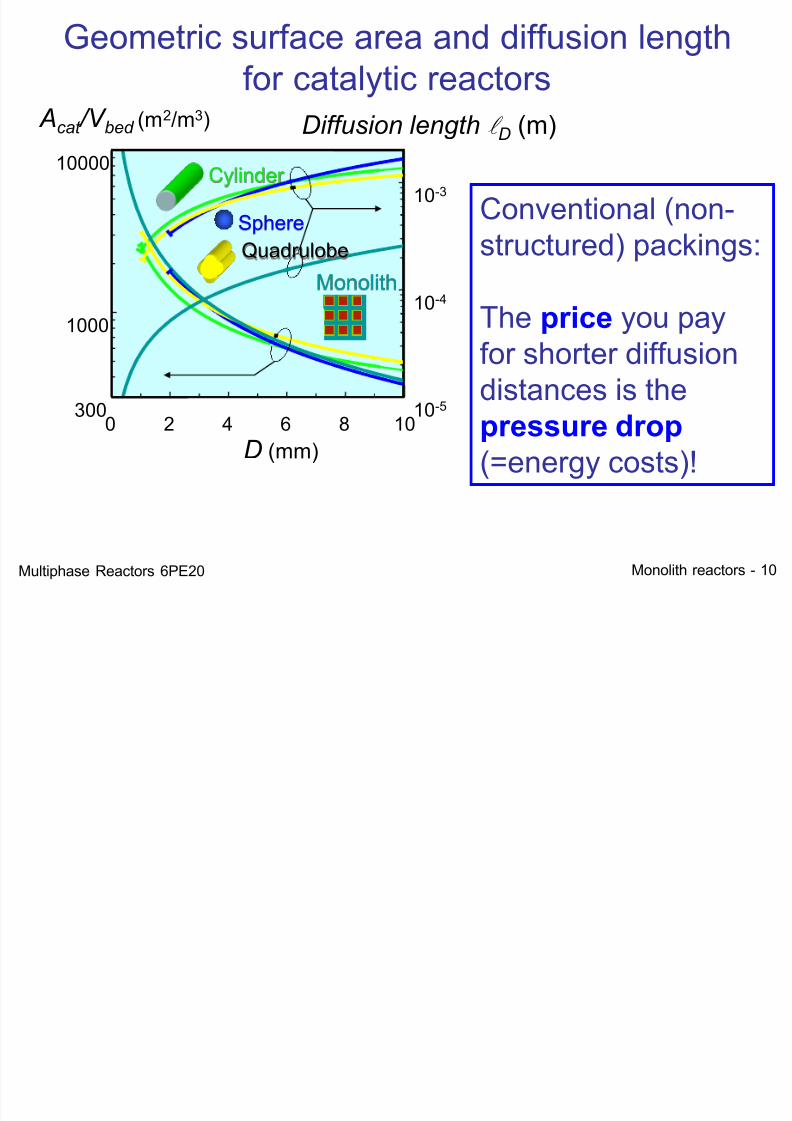
0 2 4 6 8 10 300
1000
10000
10-5
10-4
10-3 Cylinder
Quadrulobe
Monolith
Sphere
Acat /V bed (m2/m3)
D (mm)
Diffusion length
D (m)
Geometric surface area and diffusion lengthfor catalytic reactors
Conventional (non-structured) packings:
The price you payfor shorter diffusiondistances is thepressure drop (=energy costs)!
Multiphase Reactors 6PE20
7/21/2019 Monolith Multiphase 2012
http://slidepdf.com/reader/full/monolith-multiphase-2012 11/52
7/21/2019 Monolith Multiphase 2012
http://slidepdf.com/reader/full/monolith-multiphase-2012 12/52Monolith reactors - 12
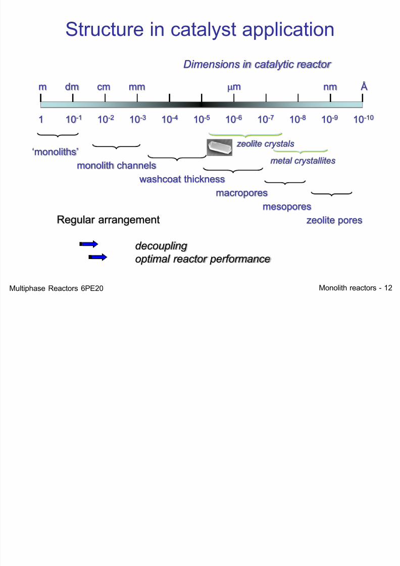
Structure in catalyst application
m dm cm mm mm nm Å
1 10-1 10-2 10-3 10-4 10-5 10-6 10-7 10-8 10-9 10-10
Dimensions in catalytic reactor
Regular arrangement
decoupling
optimal reactor performance
‘monoliths’
zeolite pores
monolith channels
washcoat thickness
macropores
mesopores
zeolite crystals
metal crystallites
Multiphase Reactors 6PE20
7/21/2019 Monolith Multiphase 2012
http://slidepdf.com/reader/full/monolith-multiphase-2012 13/52Monolith reactors - 13
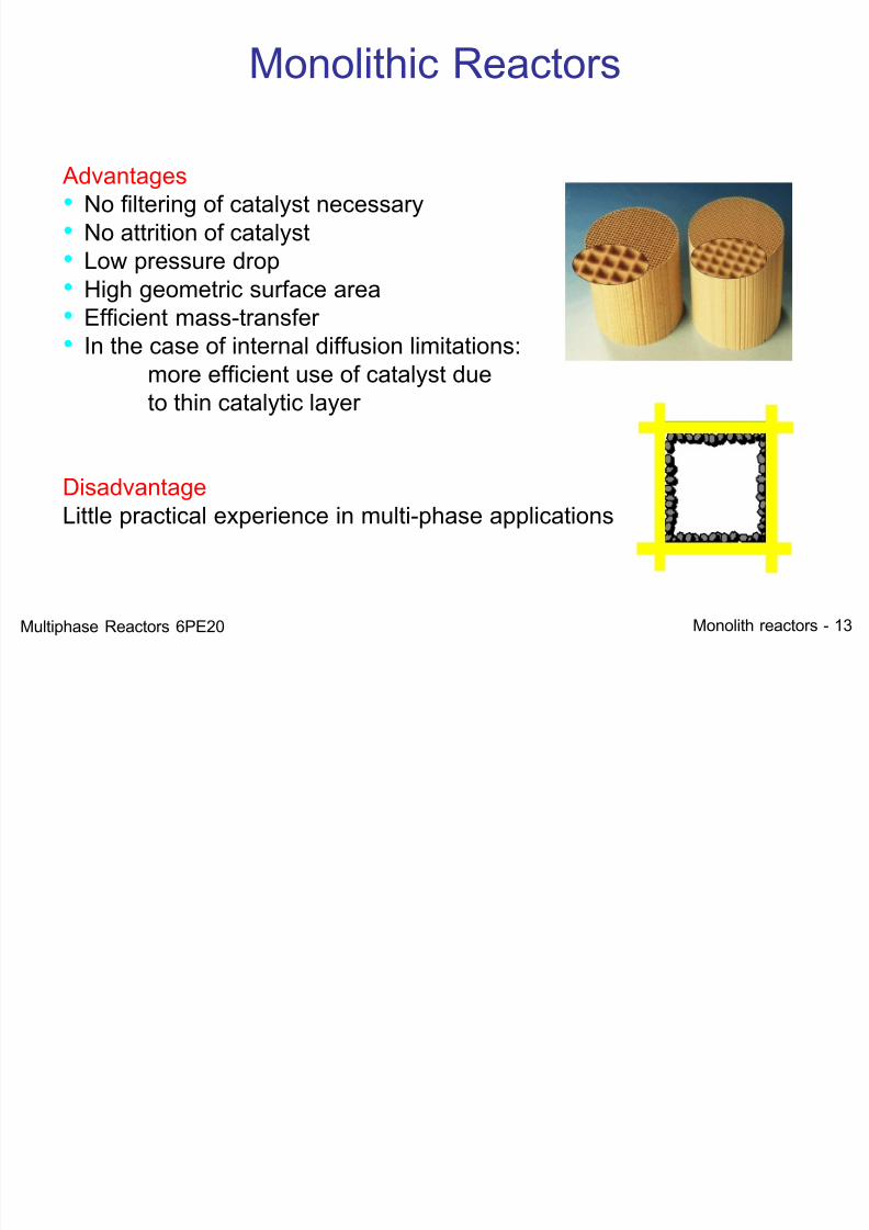
Monolithic Reactors
Advantages• No filtering of catalyst necessary• No attrition of catalyst• Low pressure drop
• High geometric surface area• Efficient mass-transfer• In the case of internal diffusion limitations:
more efficient use of catalyst dueto thin catalytic layer
DisadvantageLittle practical experience in multi-phase applications
Multiphase Reactors 6PE20
7/21/2019 Monolith Multiphase 2012
http://slidepdf.com/reader/full/monolith-multiphase-2012 14/52Monolith reactors - 14
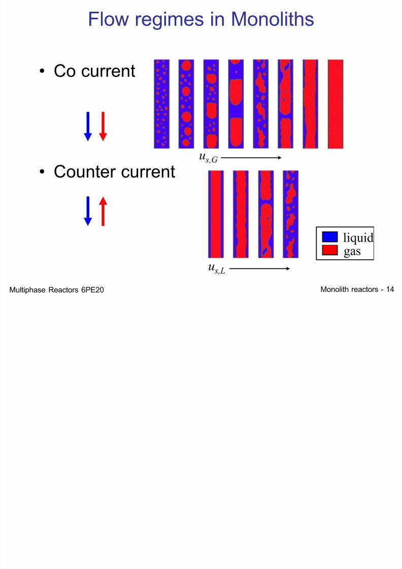
Flow regimes in Monoliths
• Co current
• Counter current
u s,L
u s,G
gasliquid
Multiphase Reactors 6PE20
7/21/2019 Monolith Multiphase 2012
http://slidepdf.com/reader/full/monolith-multiphase-2012 15/52Monolith reactors - 15
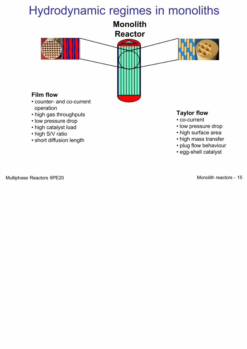
Film flow • counter- and co-current
operation• high gas throughputs• low pressure drop
• high catalyst load• high S/V ratio• short diffusion length
Monolith
Reactor
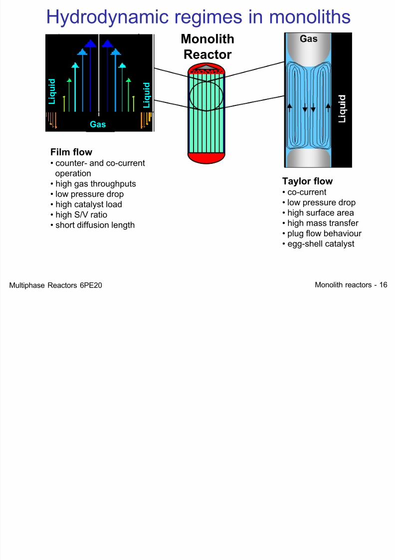
Hydrodynamic regimes in monoliths
Taylor flow• co-current
• low pressure drop• high surface area• high mass transfer• plug flow behaviour• egg-shell catalyst
Multiphase Reactors 6PE20
7/21/2019 Monolith Multiphase 2012
http://slidepdf.com/reader/full/monolith-multiphase-2012 16/52Monolith reactors - 16
Gas
L i q u i d
L i q u i d
Film flow • counter- and co-current
operation• high gas throughputs• low pressure drop
• high catalyst load• high S/V ratio• short diffusion length
Monolith
Reactor
Hydrodynamic regimes in monoliths
Taylor flow• co-current
• low pressure drop• high surface area• high mass transfer• plug flow behaviour• egg-shell catalyst
Multiphase Reactors 6PE20
7/21/2019 Monolith Multiphase 2012
http://slidepdf.com/reader/full/monolith-multiphase-2012 17/52Monolith reactors - 17
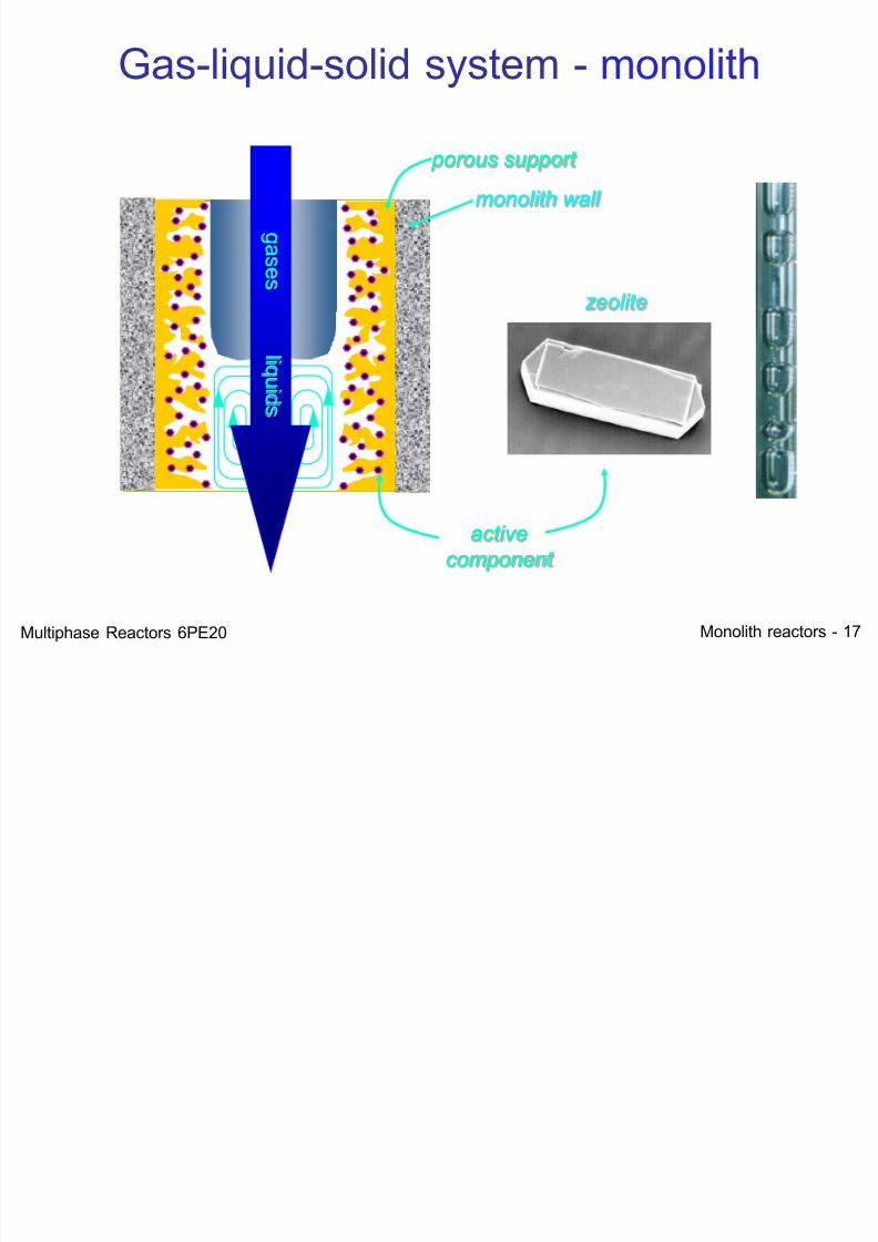
monolith wall
Gas-liquid-solid system - monolith
porous support
active
component
zeolite
g a s e s
l i q ui d s
Multiphase Reactors 6PE20
7/21/2019 Monolith Multiphase 2012
http://slidepdf.com/reader/full/monolith-multiphase-2012 18/52Monolith reactors - 18
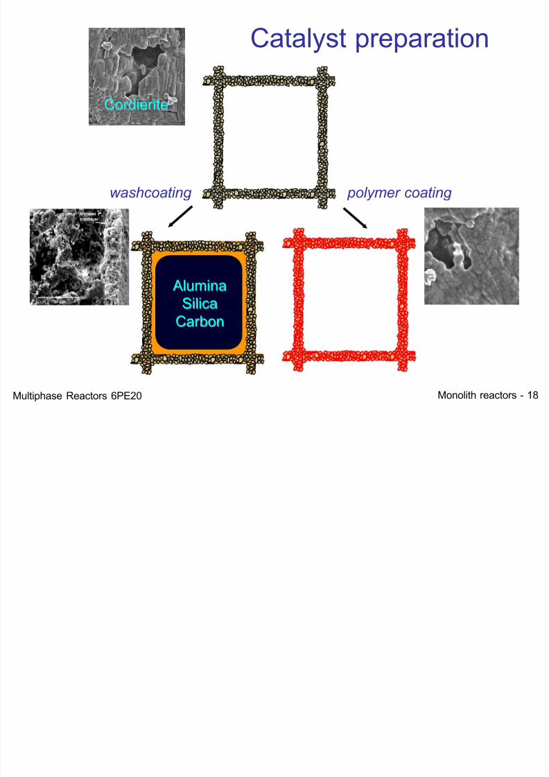
washcoating polymer coating
Catalyst preparation
AluminaSilica
Carbon
Cordierite
Multiphase Reactors 6PE20
7/21/2019 Monolith Multiphase 2012
http://slidepdf.com/reader/full/monolith-multiphase-2012 19/52Monolith reactors - 19
Co-Current Applications
(Taylor Flow)
Multiphase Reactors 6PE20
7/21/2019 Monolith Multiphase 2012
http://slidepdf.com/reader/full/monolith-multiphase-2012 20/52Monolith reactors - 20
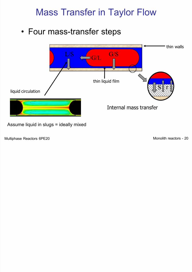
S r
Mass Transfer in Taylor Flow
• Four mass-transfer steps
G/LG/SL/S
liquid circulation
thin liquid film
Internal mass transfer
thin walls
Assume liquid in slugs = ideally mixed
Multiphase Reactors 6PE20
M T f i T l Fl
7/21/2019 Monolith Multiphase 2012
http://slidepdf.com/reader/full/monolith-multiphase-2012 21/52Monolith reactors - 21
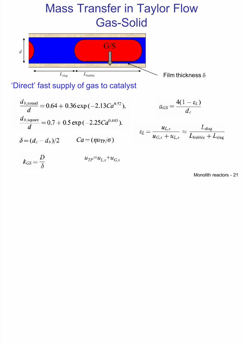
Mass Transfer in Taylor FlowGas-Solid
G/Sd
‘Direct’ fast supply of gas to catalyst
Film thickness d L slug Lbubble
uTP =u L,s+uG,s
7/21/2019 Monolith Multiphase 2012
http://slidepdf.com/reader/full/monolith-multiphase-2012 22/52Monolith reactors - 22
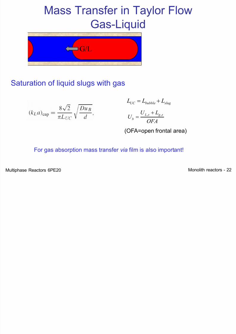
Mass Transfer in Taylor FlowGas-Liquid
slug bubbleUC L L L
Saturation of liquid slugs with gas
OFA
LU U
s g s L
b
,,
(OFA=open frontal area)
For gas absorption mass transfer via film is also important!
G/L
Multiphase Reactors 6PE20
7/21/2019 Monolith Multiphase 2012
http://slidepdf.com/reader/full/monolith-multiphase-2012 23/52Monolith reactors - 23
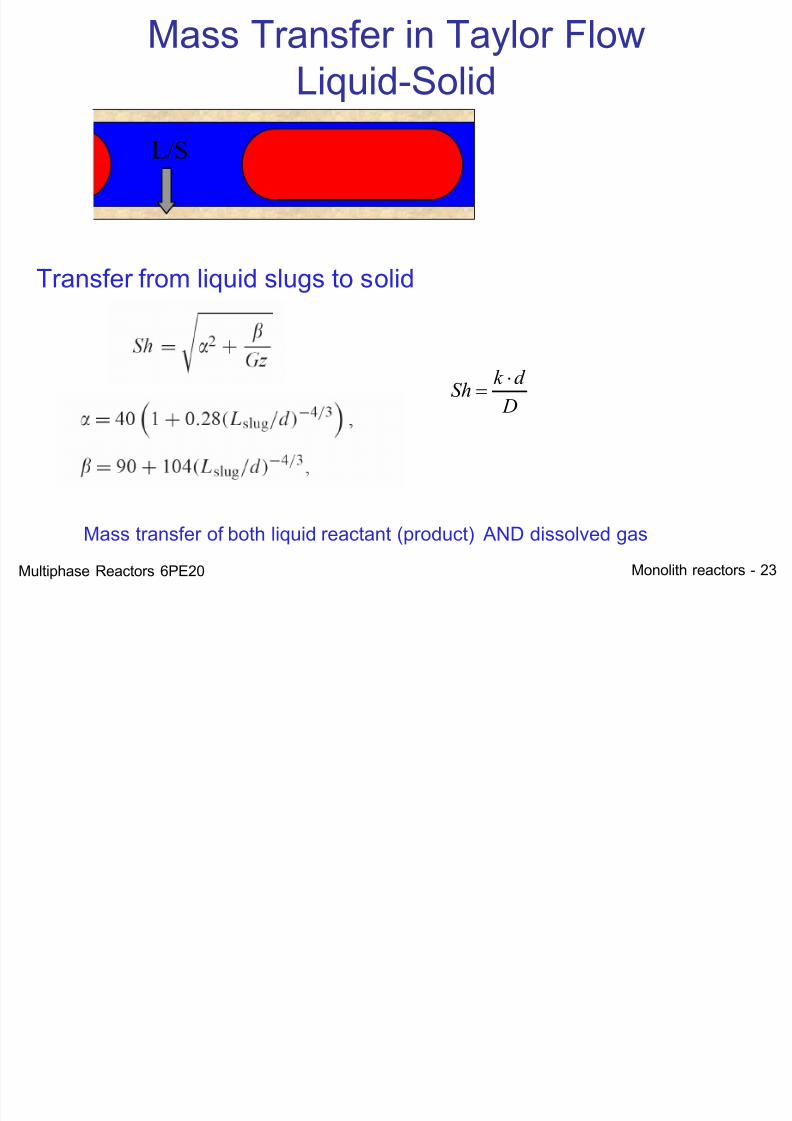
Mass Transfer in Taylor FlowLiquid-Solid
Transfer from liquid slugs to solid
D
d k Sh
Mass transfer of both liquid reactant (product) AND dissolved gas
L/S
Multiphase Reactors 6PE20
7/21/2019 Monolith Multiphase 2012
http://slidepdf.com/reader/full/monolith-multiphase-2012 24/52
Monolith reactors - 24
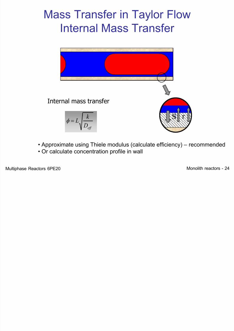
Mass Transfer in Taylor FlowInternal Mass Transfer
S r
Internal mass transfer
eff D
k
L
• Approximate using Thiele modulus (calculate efficiency) – recommended• Or calculate concentration profile in wall
Multiphase Reactors 6PE20
7/21/2019 Monolith Multiphase 2012
http://slidepdf.com/reader/full/monolith-multiphase-2012 25/52
Monolith reactors - 25
S r
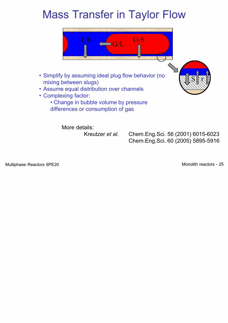
Mass Transfer in Taylor Flow
G/L G/SL/S
• Simplify by assuming ideal plug flow behavior (nomixing between slugs)
• Assume equal distribution over channels• Complexing factor:
• Change in bubble volume by pressuredifferences or consumption of gas
More details:Kreutzer et al. Chem.Eng.Sci. 56 (2001) 6015-6023
Chem.Eng.Sci. 60 (2005) 5895-5916
Multiphase Reactors 6PE20
7/21/2019 Monolith Multiphase 2012
http://slidepdf.com/reader/full/monolith-multiphase-2012 26/52
Monolith reactors - 26
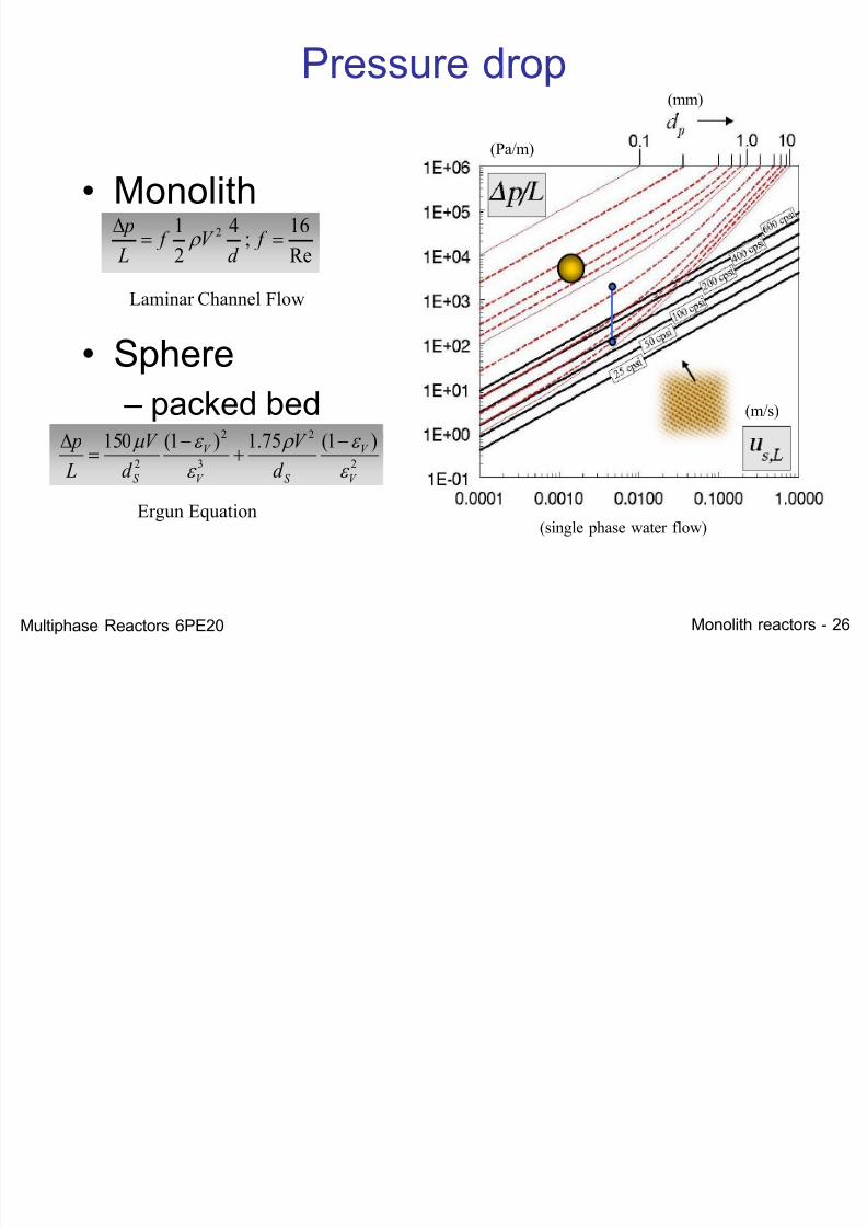
Pressure drop
(single phase water flow)
(m/s)
(Pa/m)
• Monolith
• Sphere – packed bed
Laminar Channel Flow
Ergun Equation
(mm)
Re
16;
4
2
1 2
f d
V f L
p
2
2
3
2
2 )1(75.1)1(150V
V
S V
V
S d V
d V
L p
m
Multiphase Reactors 6PE20
7/21/2019 Monolith Multiphase 2012
http://slidepdf.com/reader/full/monolith-multiphase-2012 27/52
Monolith reactors - 27
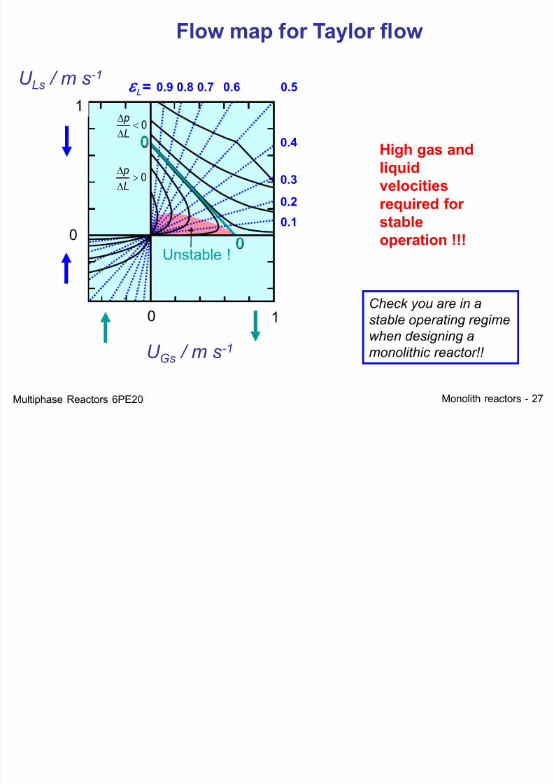
Unstable !
0
L
p
0
L
p
L= 0.9 0.8 0.7 0.6 0.5
0.4
0.3
0.2
0.1
U Gs / m s-1
U Ls / m s-1
0 1
0
1
0
0
Flow map for Taylor flow
High gas and
liquid
velocitiesrequired for
stable
operation !!!
Check you are in a
stable operating regime
when designing a
monolithic reactor!!
Multiphase Reactors 6PE20
7/21/2019 Monolith Multiphase 2012
http://slidepdf.com/reader/full/monolith-multiphase-2012 28/52
Monolith reactors - 28
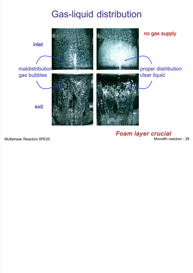
Gas-liquid distribution
Foam layer cruc ial
no gas supply
maldistributiongas bubbles
proper distributionclear liquid
exit
inlet
Multiphase Reactors 6PE20
M T f li it d ti
7/21/2019 Monolith Multiphase 2012
http://slidepdf.com/reader/full/monolith-multiphase-2012 29/52
Monolith reactors - 29
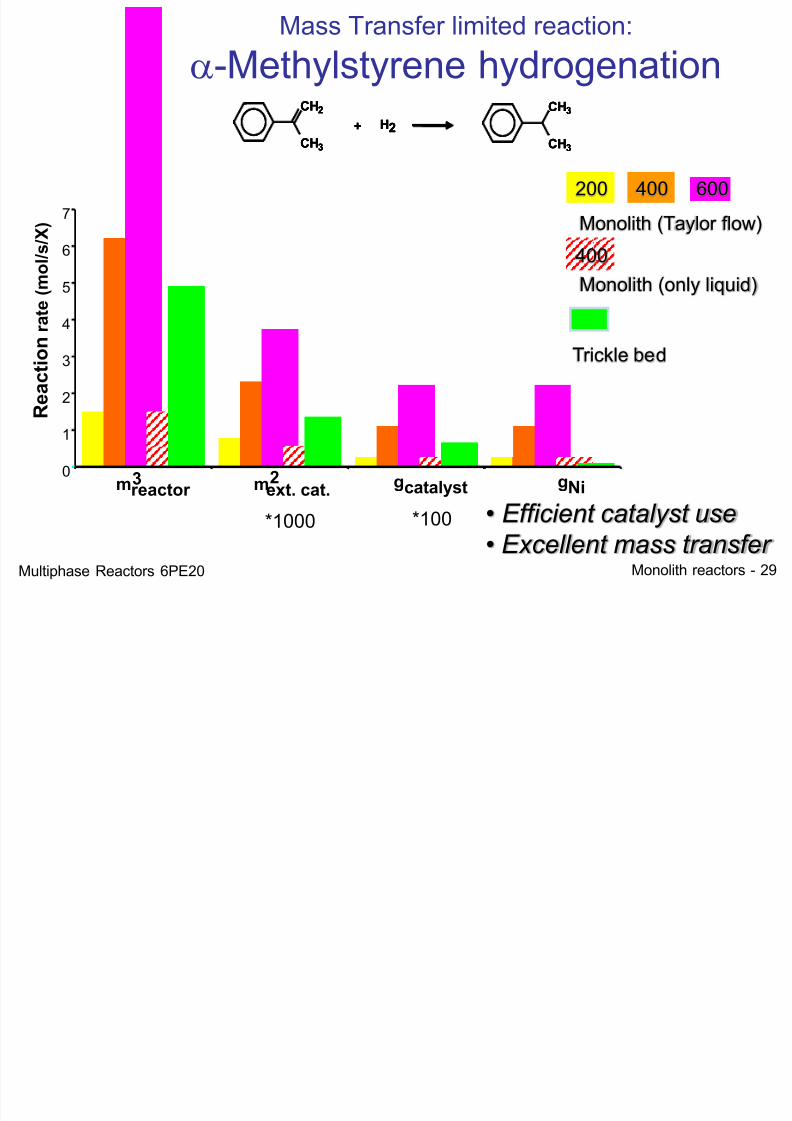
Mass Transfer limited reaction:
a-Methylstyrene hydrogenation
• Efficient catalyst use
• Excellent mass transfer
Monolith (Taylor flow)
Trickle bed
400 600200
0
1
2
3
4
5
6
7
R
e a c t i o n r a t e ( m o l / s / X )
m 3 reactor m 2
ext. cat.
*1000
g catalyst
*100
g Ni
Monolith (only liquid)
400
CH2
CH3
+ H2
CH3
CH3
CH2
CH3
+ H2
CH3
CH3
CH2
CH3
+ H2
CH3
CH3
Multiphase Reactors 6PE20
7/21/2019 Monolith Multiphase 2012
http://slidepdf.com/reader/full/monolith-multiphase-2012 30/52
Monolith reactors - 30
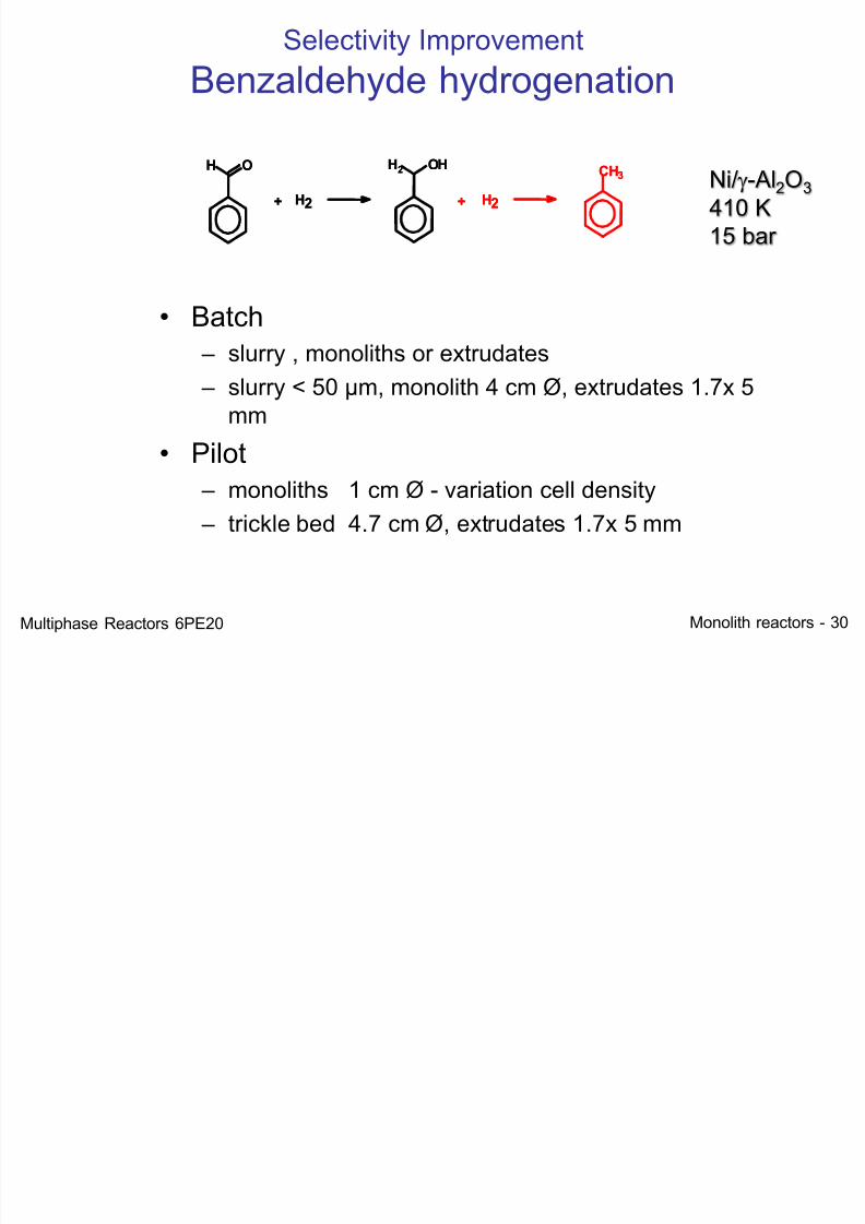
Selectivity Improvement
Benzaldehyde hydrogenation
Ni/g-Al2O3 410 K15 bar
• Batch – slurry , monoliths or extrudates
– slurry < 50 µm, monolith 4 cm Ø, extrudates 1.7x 5mm
• Pilot – monoliths 1 cm Ø - variation cell density
– trickle bed 4.7 cm Ø, extrudates 1.7x 5 mm
OH
+ H2
OHH2
H2+
CH3OH
+ H2
OHH2
H2+
CH3
Multiphase Reactors 6PE20
7/21/2019 Monolith Multiphase 2012
http://slidepdf.com/reader/full/monolith-multiphase-2012 31/52
Monolith reactors - 31
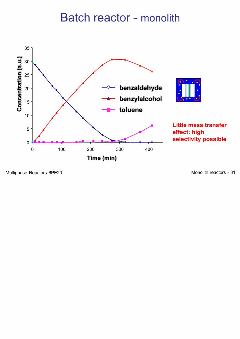
Batch reactor - monolith
0
5
10
15
20
25
30
35
0 100 200 300 400
Time (min)
C o n c e n t r a t i o n ( a . u . )
benzaldehyde
benzylalcohol
toluene
Little mass transfereffect: high
selectivity possible
Multiphase Reactors 6PE20
7/21/2019 Monolith Multiphase 2012
http://slidepdf.com/reader/full/monolith-multiphase-2012 32/52
Monolith reactors - 32
0
40
80
120
160
0 1 2 3 4
Time (h)
C o n c e n t r a
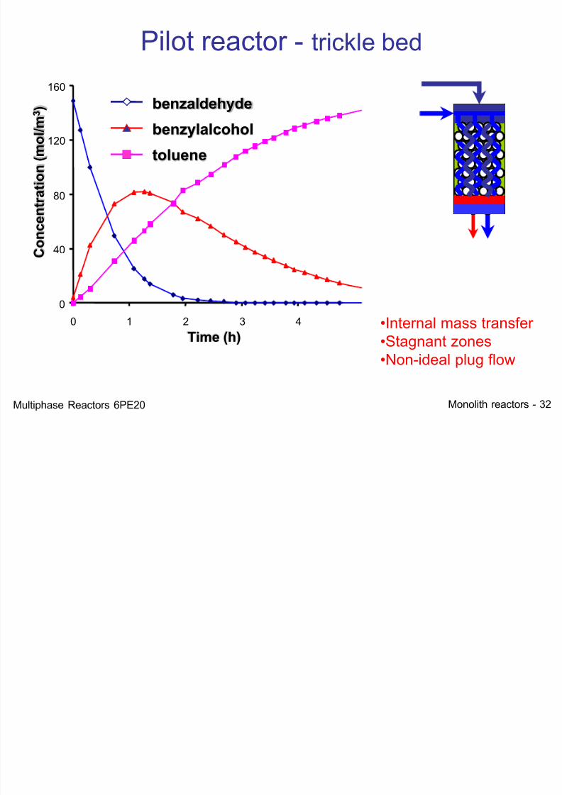
t i o n ( m o l / m 3 ) benzaldehyde
benzylalcohol
toluene
Pilot reactor - trickle bed
•Internal mass transfer•Stagnant zones•Non-ideal plug flow
Multiphase Reactors 6PE20
7/21/2019 Monolith Multiphase 2012
http://slidepdf.com/reader/full/monolith-multiphase-2012 33/52
Monolith reactors - 33
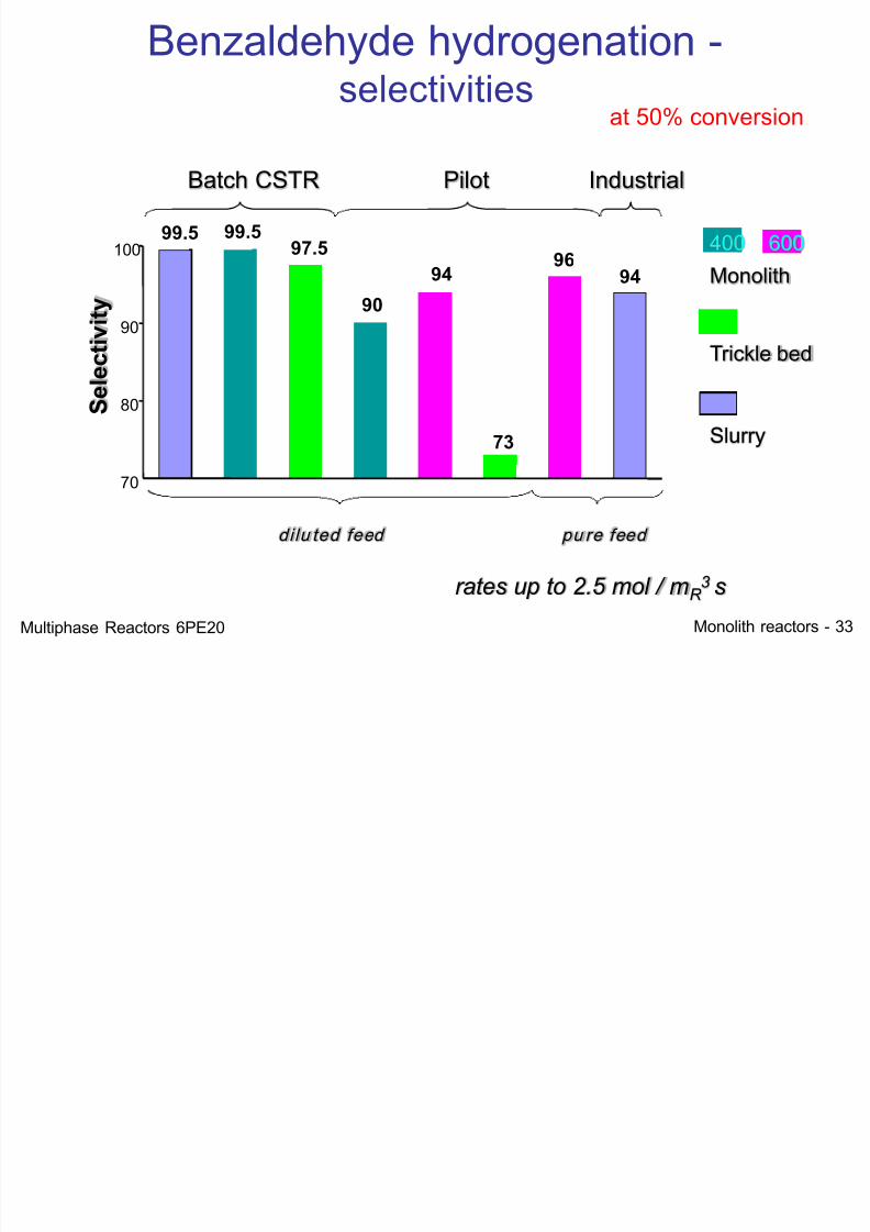
pu re feed
600
Monolith
Trickle bed
400
Slurry
Batch CSTR Pilot Industrial
dilu ted feed
Benzaldehyde hydrogenation -selectivities
rates up to 2.5 mol / mR 3 s
at 50% conversion
99.5 99.5
90
94
73
96 94
S e l e c t i v i t y
70
80
90
100 97.5
Multiphase Reactors 6PE20
7/21/2019 Monolith Multiphase 2012
http://slidepdf.com/reader/full/monolith-multiphase-2012 34/52
Monolith reactors - 34
Taylor-flow - Summary
• Only co-current
• Very high mass transfer rates
• Stable operation only at high superficialvelocities
• Gas-liquid ratio between 1:3 and 3:1
Most suited for fast reactions
Multiphase Reactors 6PE20
7/21/2019 Monolith Multiphase 2012
http://slidepdf.com/reader/full/monolith-multiphase-2012 35/52
Monolith reactors - 35
Counter-Current Applications
(Film Flow)
Multiphase Reactors 6PE20
7/21/2019 Monolith Multiphase 2012
http://slidepdf.com/reader/full/monolith-multiphase-2012 36/52
Monolith reactors - 36
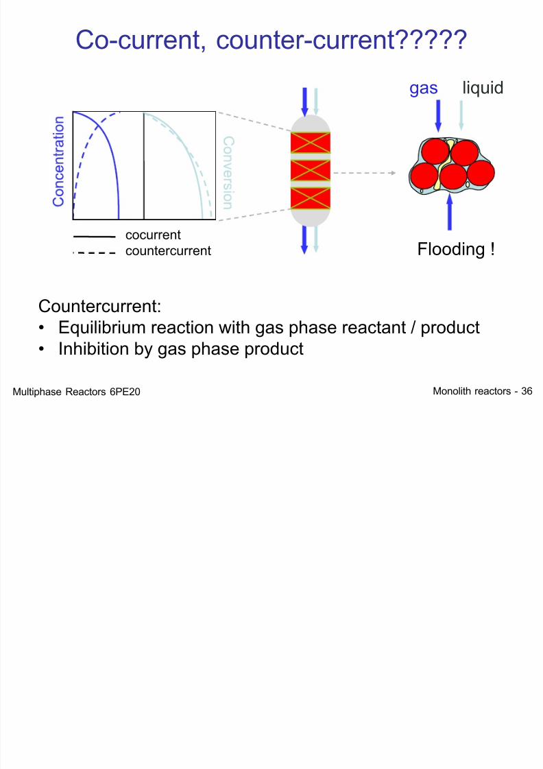
gas liquid
Flooding !cocurrentcountercurrent
Co-current, counter-current?????
Countercurrent:• Equilibrium reaction with gas phase reactant / product• Inhibition by gas phase product
Multiphase Reactors 6PE20
Counter-current gas/liquid flow; how to avoid
7/21/2019 Monolith Multiphase 2012
http://slidepdf.com/reader/full/monolith-multiphase-2012 37/52
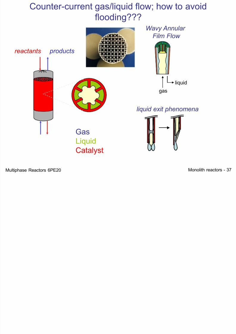
Monolith reactors - 37
GasLiquidCatalyst
reactants products
liquid exit phenomena
Wavy Annular
Film Flow
gas liquid
Counter-current gas/liquid flow; how to avoidflooding???
Multiphase Reactors 6PE20
7/21/2019 Monolith Multiphase 2012
http://slidepdf.com/reader/full/monolith-multiphase-2012 38/52
Monolith reactors - 38
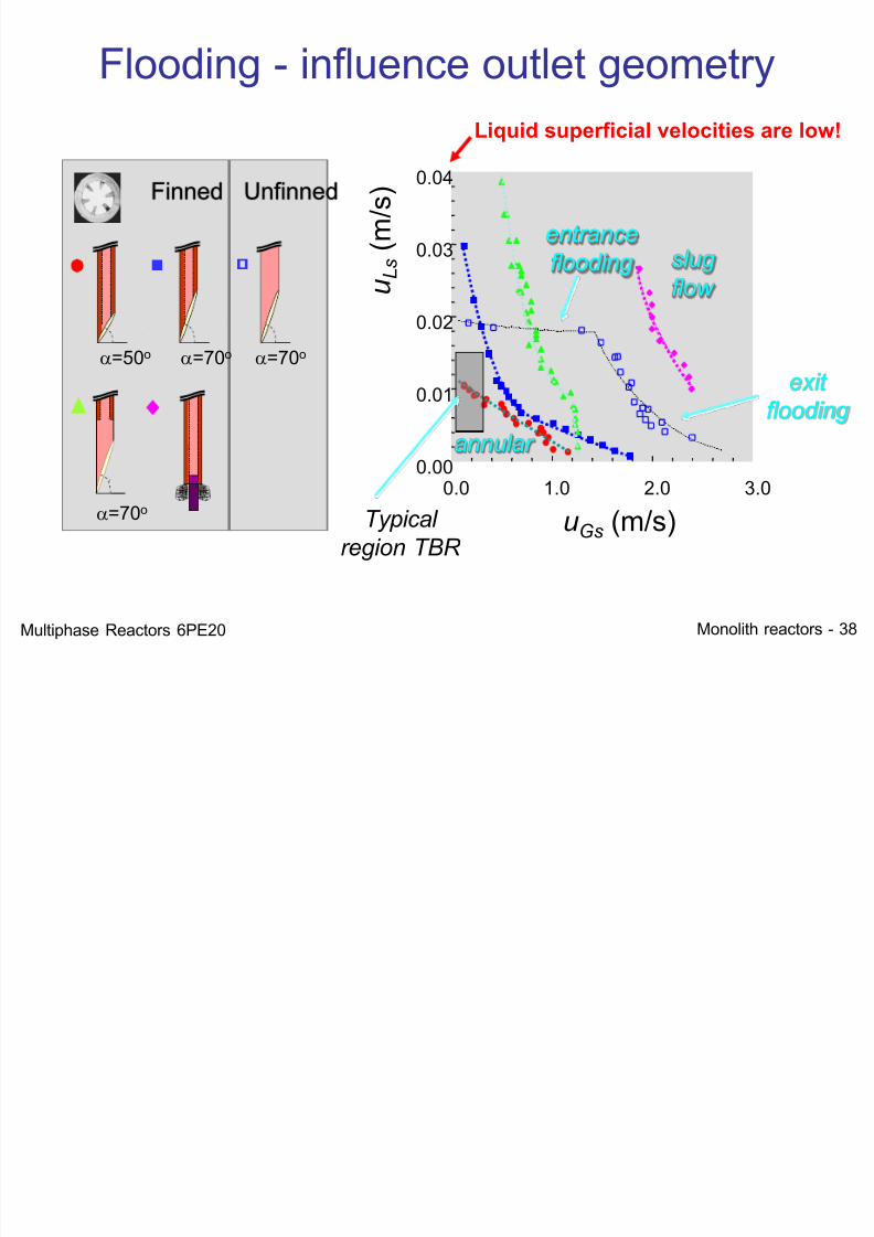
a=50o a=70o a=70o
a=70o 0.0 1.0 2.0 3.0
0.00
0.01
0.02
0.03
0.04
entrance
flooding
exit
flooding
Typical
region TBR
annular
slug
flow
Finned Unfinned
uGs (m/s)
u L s
( m / s )
Flooding - influence outlet geometry
Liquid superficial velocities are low!
Multiphase Reactors 6PE20
Monolith
7/21/2019 Monolith Multiphase 2012
http://slidepdf.com/reader/full/monolith-multiphase-2012 39/52
Monolith reactors - 39
0.00 0.50 1.00 1.50 2.000.00
0.02
0.03
0.05
0.06
0.08
u s ,L
u s ,G
0.00 0.50 1.00 1.50 2.000.00
0.02
0.03
0.05
0.06
0.08
u s ,L
u s ,G
0.00 0.50 1.00 1.50 2.000.00
0.02
0.03
0.05
0.06
0.08
u s ,L
u s ,G
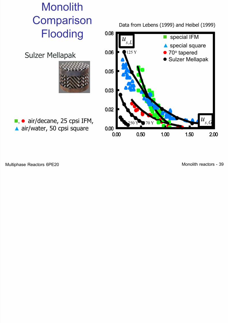
special IFM
▲ special square 70o tapered Sulzer Mellapak
MonolithComparison
Flooding
, air/decane, 25 cpsi IFM,▲ air/water, 50 cpsi square
Data from Lebens (1999) and Heibel (1999)
250 Y
125 Y
170 Y
Sulzer Mellapak
Multiphase Reactors 6PE20
7/21/2019 Monolith Multiphase 2012
http://slidepdf.com/reader/full/monolith-multiphase-2012 40/52
Monolith reactors - 40
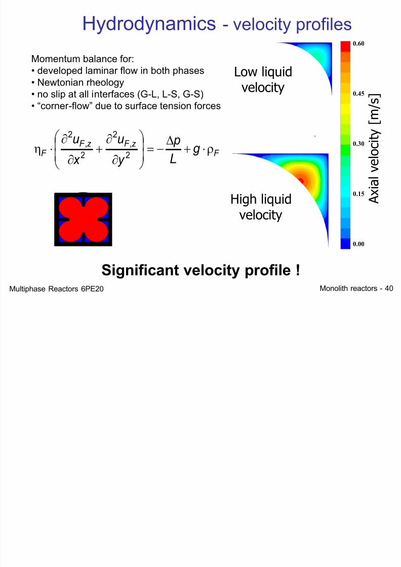
F z F z F
F g L p
y u
x u
2
,2
2
,2
Momentum balance for:
• developed laminar flow in both phases• Newtonian rheology• no slip at all interfaces (G-L, L-S, G-S)• “corner -flow” due to surface tension forces
High liquidvelocity
A x i a l v e l o c i t y [ m / s ]
0.60
0.45
0.30
0.15
0.00
Low liquidvelocity
Hydrodynamics - velocity profiles
Significant velocity profile !Multiphase Reactors 6PE20
7/21/2019 Monolith Multiphase 2012
http://slidepdf.com/reader/full/monolith-multiphase-2012 41/52
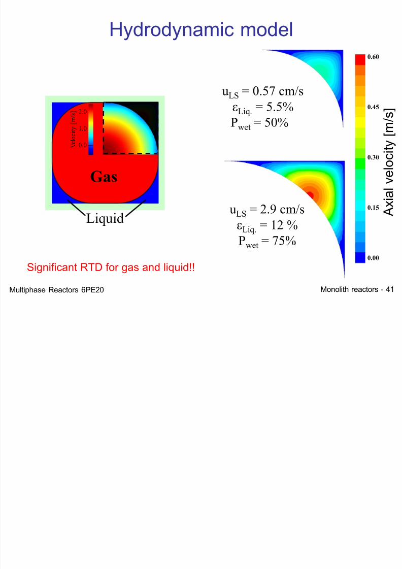
Monolith reactors - 41
Liquid
2.0
1.0
0.0 V e l o c i t y [ m / s ]
Gas
Hydrodynamic model
uLS = 2.9 cm/sLiq. = 12 %
Pwet = 75%
uLS = 0.57 cm/s
Liq. = 5.5%
Pwet = 50%
A
x i a l v e l o c i t y
[ m / s ]
0.60
0.45
0.30
0.15
0.00
Significant RTD for gas and liquid!!
Multiphase Reactors 6PE20
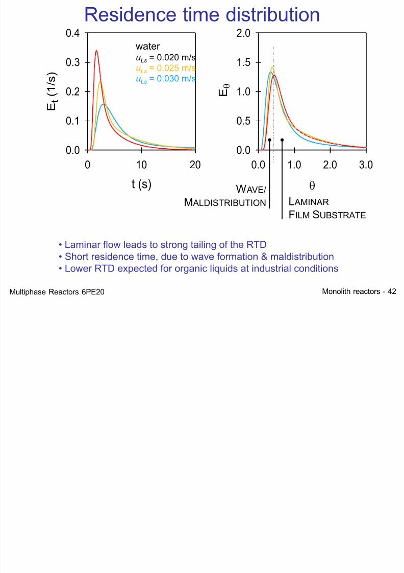
Residence time distribution
7/21/2019 Monolith Multiphase 2012
http://slidepdf.com/reader/full/monolith-multiphase-2012 42/52
Monolith reactors - 42
t (s)
0 10 20
Et(1/s)
0.0
0.1
0.2
0.3
0.4
0.0 1.0 2.0 3.0
E
0.0
0.5
1.0
1.5
2.0
Residence time distribution
W AVE/
M ALDISTRIBUTION L AMINAR
FILM SUBSTRATE
wateruLs = 0.020 m/su
Ls = 0.025 m/s
uLs = 0.030 m/s
• Laminar flow leads to strong tailing of the RTD• Short residence time, due to wave formation & maldistribution• Lower RTD expected for organic liquids at industrial conditions
Multiphase Reactors 6PE20
7/21/2019 Monolith Multiphase 2012
http://slidepdf.com/reader/full/monolith-multiphase-2012 43/52
Monolith reactors - 43
0.00 0.05 0.10
Sh
0
5
10
15
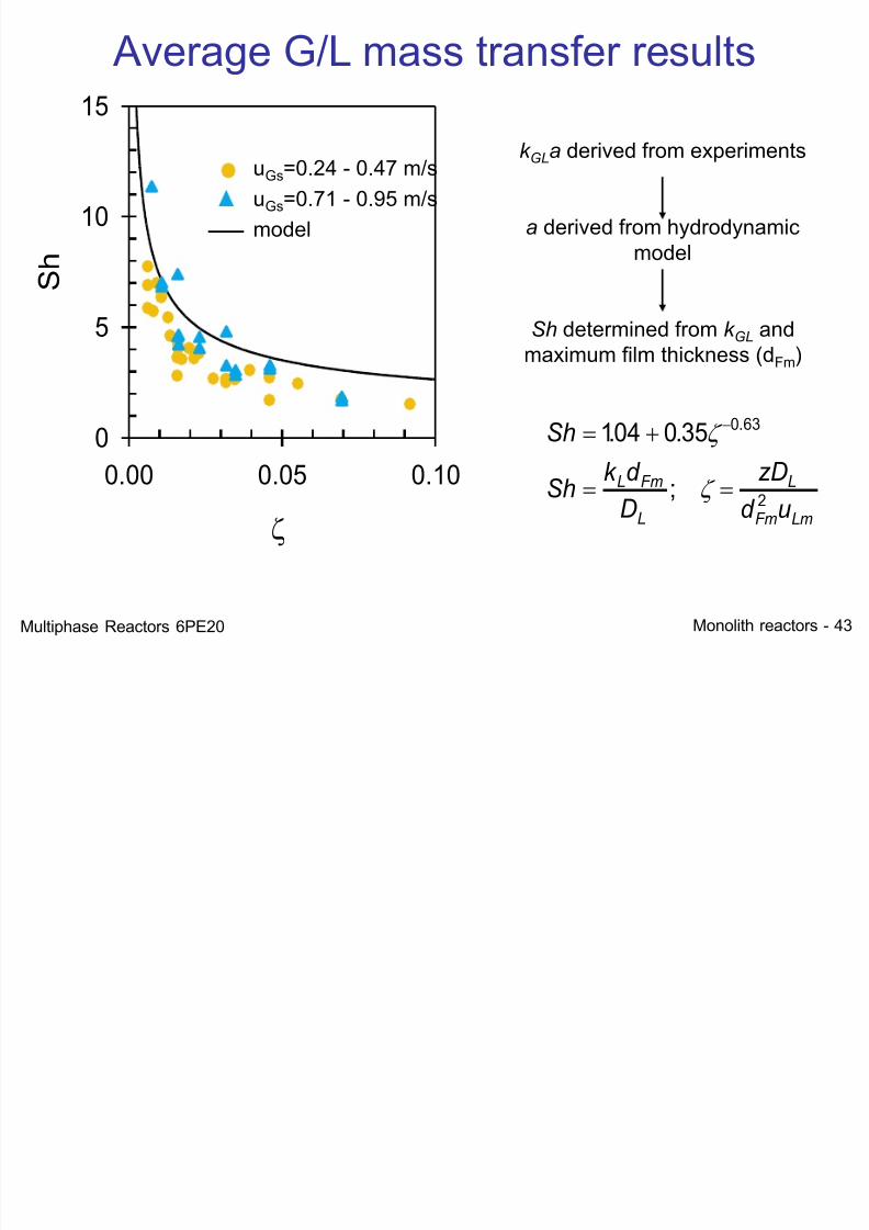
Average G/L mass transfer results
k GLa derived from experiments
a derived from hydrodynamicmodel
Sh determined from k GL andmaximum film thickness (dFm)
Sh
Sh k d
D
zD
d u
L Fm
L
L
Fm Lm
104 0 35 0 63
2
. .
;
.
uGs=0.24 - 0.47 m/s
uGs=0.71 - 0.95 m/s
model
Multiphase Reactors 6PE20
7/21/2019 Monolith Multiphase 2012
http://slidepdf.com/reader/full/monolith-multiphase-2012 44/52
Monolith reactors - 44
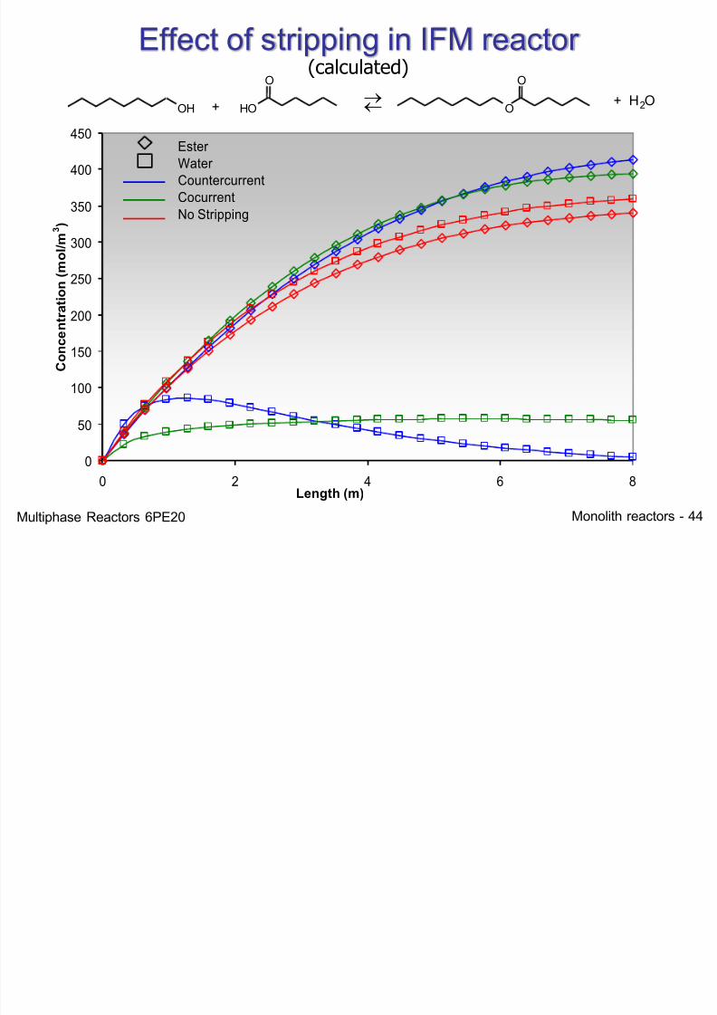
0
50
100
150
200
250
300
350
400
450
0 2 4 6 8
Length (m)
C o n c e n t r a t i o n ( m o l / m 3 )
Ester
Water
Countercurrent
Cocurrent
No Stripping
(calculated)
Effect of stripping in IFM reactor
O H O H
O
O
O
+
+ H2O
Multiphase Reactors 6PE20
7/21/2019 Monolith Multiphase 2012
http://slidepdf.com/reader/full/monolith-multiphase-2012 45/52
Monolith reactors - 45
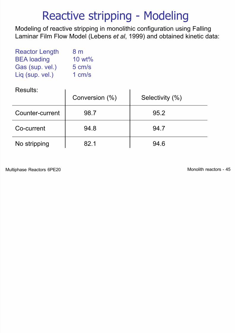
Reactive stripping - Modeling Modeling of reactive stripping in monolithic configuration using FallingLaminar Film Flow Model (Lebens et al , 1999) and obtained kinetic data:
Reactor Length 8 mBEA loading 10 wt%Gas (sup. vel.) 5 cm/sLiq (sup. vel.) 1 cm/s
Results:Conversion (%) Selectivity (%)
Counter-current 98.7 95.2
Co-current 94.8 94.7
No stripping 82.1 94.6
Multiphase Reactors 6PE20
7/21/2019 Monolith Multiphase 2012
http://slidepdf.com/reader/full/monolith-multiphase-2012 46/52
Monolith reactors - 46
Film Flow - Summary
• Laminar flow• Mass transfer relatively slow (diffusion)
• Residence time distribution
• Low liquid superficial velocities• Flooding risk at exit
• Counter Current operation !!!
Multiphase Reactors 6PE20
7/21/2019 Monolith Multiphase 2012
http://slidepdf.com/reader/full/monolith-multiphase-2012 47/52
Monolith reactors - 47
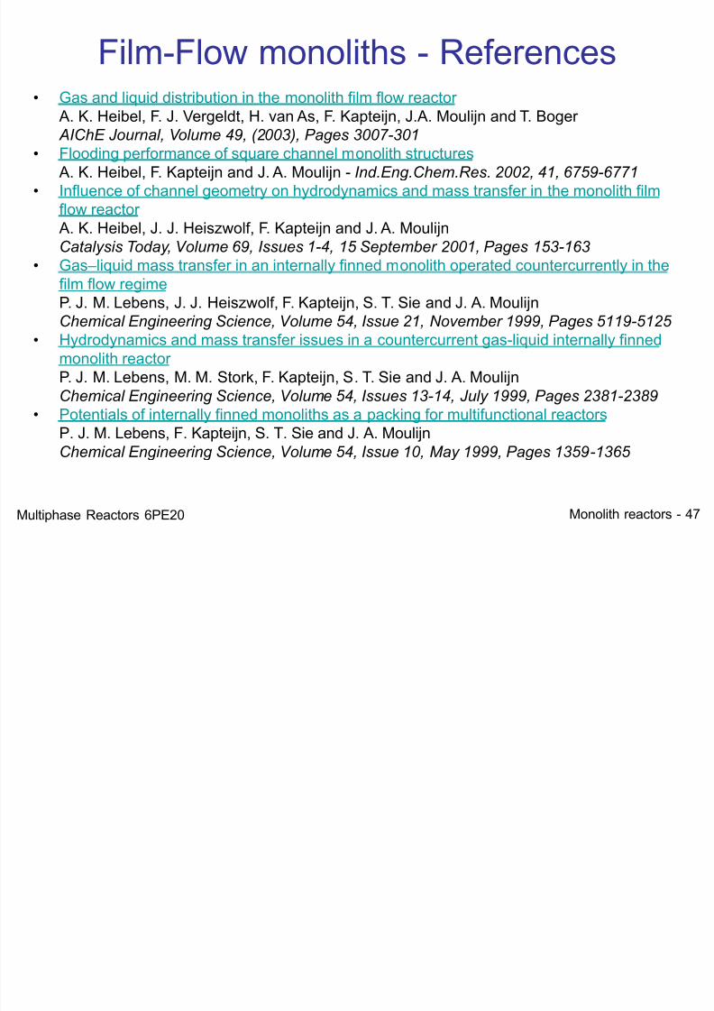
Film-Flow monoliths - References• Gas and liquid distribution in the monolith film flow reactor
A. K. Heibel, F. J. Vergeldt, H. van As, F. Kapteijn, J.A. Moulijn and T. Boger AIChE Journal, Volume 49, (2003), Pages 3007-301
• Flooding performance of square channel monolith structures A. K. Heibel, F. Kapteijn and J. A. Moulijn - Ind.Eng.Chem.Res. 2002, 41, 6759-6771
• Influence of channel geometry on hydrodynamics and mass transfer in the monolith filmflow reactor
A. K. Heibel, J. J. Heiszwolf, F. Kapteijn and J. A. Moulijn
Catalysis Today, Volume 69, Issues 1-4, 15 September 2001, Pages 153-163 • Gas –liquid mass transfer in an internally finned monolith operated countercurrently in thefilm flow regime P. J. M. Lebens, J. J. Heiszwolf, F. Kapteijn, S. T. Sie and J. A. MoulijnChemical Engineering Science, Volume 54, Issue 21, November 1999, Pages 5119-5125
• Hydrodynamics and mass transfer issues in a countercurrent gas-liquid internally finnedmonolith reactor
P. J. M. Lebens, M. M. Stork, F. Kapteijn, S. T. Sie and J. A. MoulijnChemical Engineering Science, Volume 54, Issues 13-14, July 1999, Pages 2381-2389
• Potentials of internally finned monoliths as a packing for multifunctional reactors P. J. M. Lebens, F. Kapteijn, S. T. Sie and J. A. MoulijnChemical Engineering Science, Volume 54, Issue 10, May 1999, Pages 1359-1365
Multiphase Reactors 6PE20
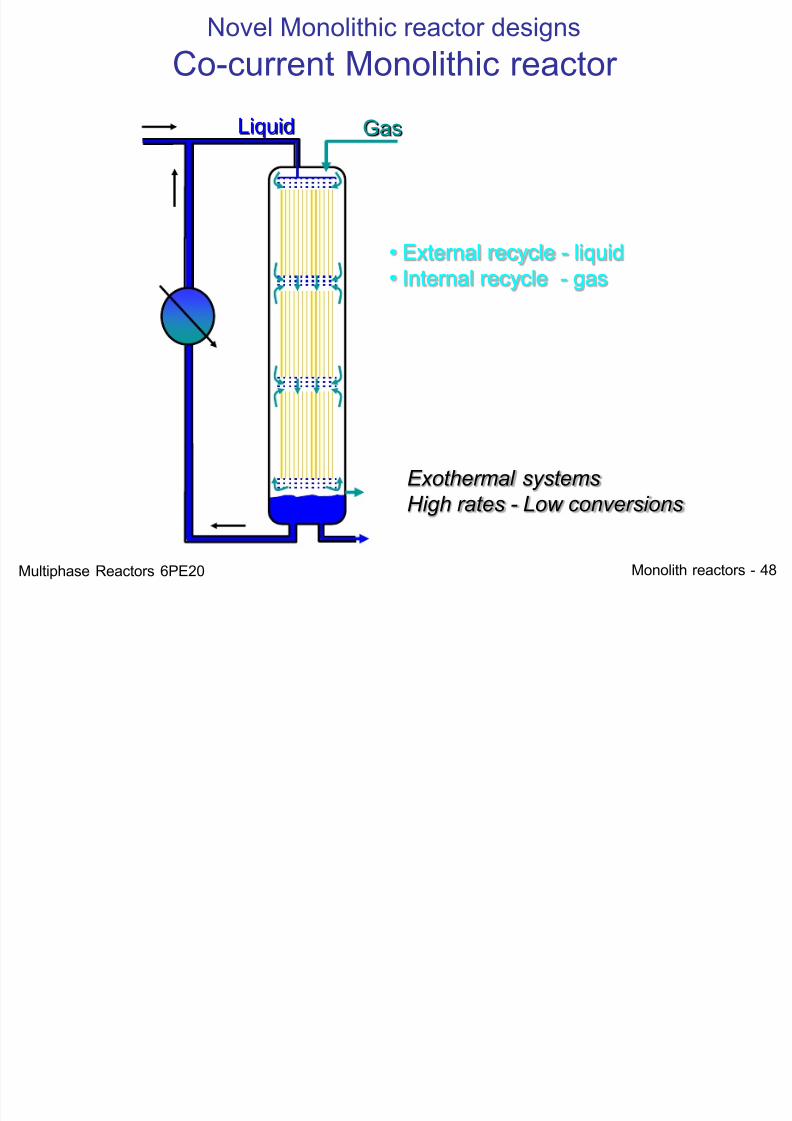
Novel Monolithic reactor designs
7/21/2019 Monolith Multiphase 2012
http://slidepdf.com/reader/full/monolith-multiphase-2012 48/52
Monolith reactors - 48
• External recycle - liquid
• Internal recycle - gas
Exothermal systems
High rates - Low conversions
Liquid Gas
Novel Monolithic reactor designs
Co-current Monolithic reactor
Multiphase Reactors 6PE20
Novel Monolithic reactor designs
7/21/2019 Monolith Multiphase 2012
http://slidepdf.com/reader/full/monolith-multiphase-2012 49/52
Monolith reactors - 49
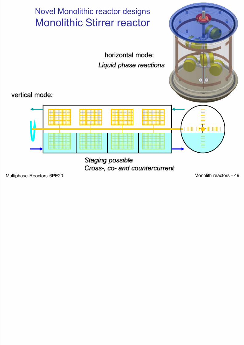
vertical mode:
Staging possible
Cross-, co- and countercurrent
Liquid phase reactions
horizontal mode:
Novel Monolithic reactor designs
Monolithic Stirrer reactor
Multiphase Reactors 6PE20
7/21/2019 Monolith Multiphase 2012
http://slidepdf.com/reader/full/monolith-multiphase-2012 50/52
Monolith reactors - 50
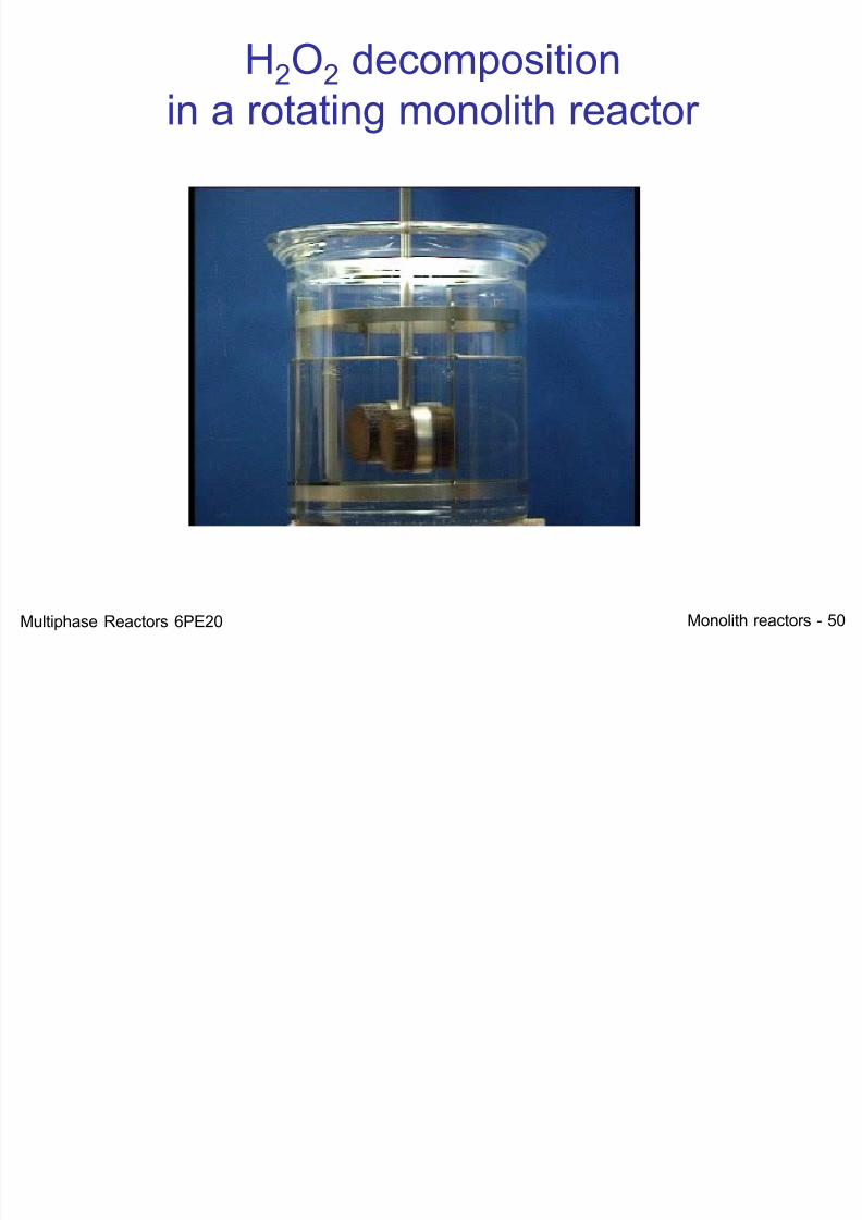
H2O2 decompositionin a rotating monolith reactor
Multiphase Reactors 6PE20
7/21/2019 Monolith Multiphase 2012
http://slidepdf.com/reader/full/monolith-multiphase-2012 51/52
Monolith reactors - 51
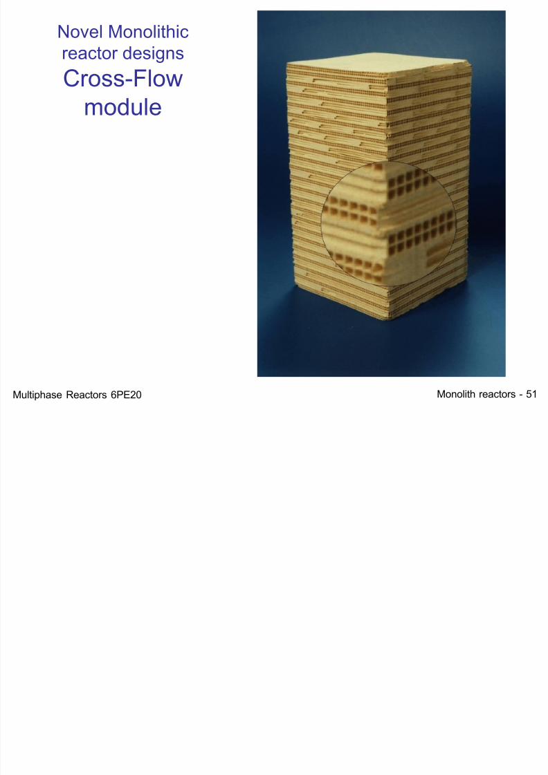
Novel Monolithicreactor designs
Cross-Flow
module
Multiphase Reactors 6PE20
7/21/2019 Monolith Multiphase 2012
http://slidepdf.com/reader/full/monolith-multiphase-2012 52/52
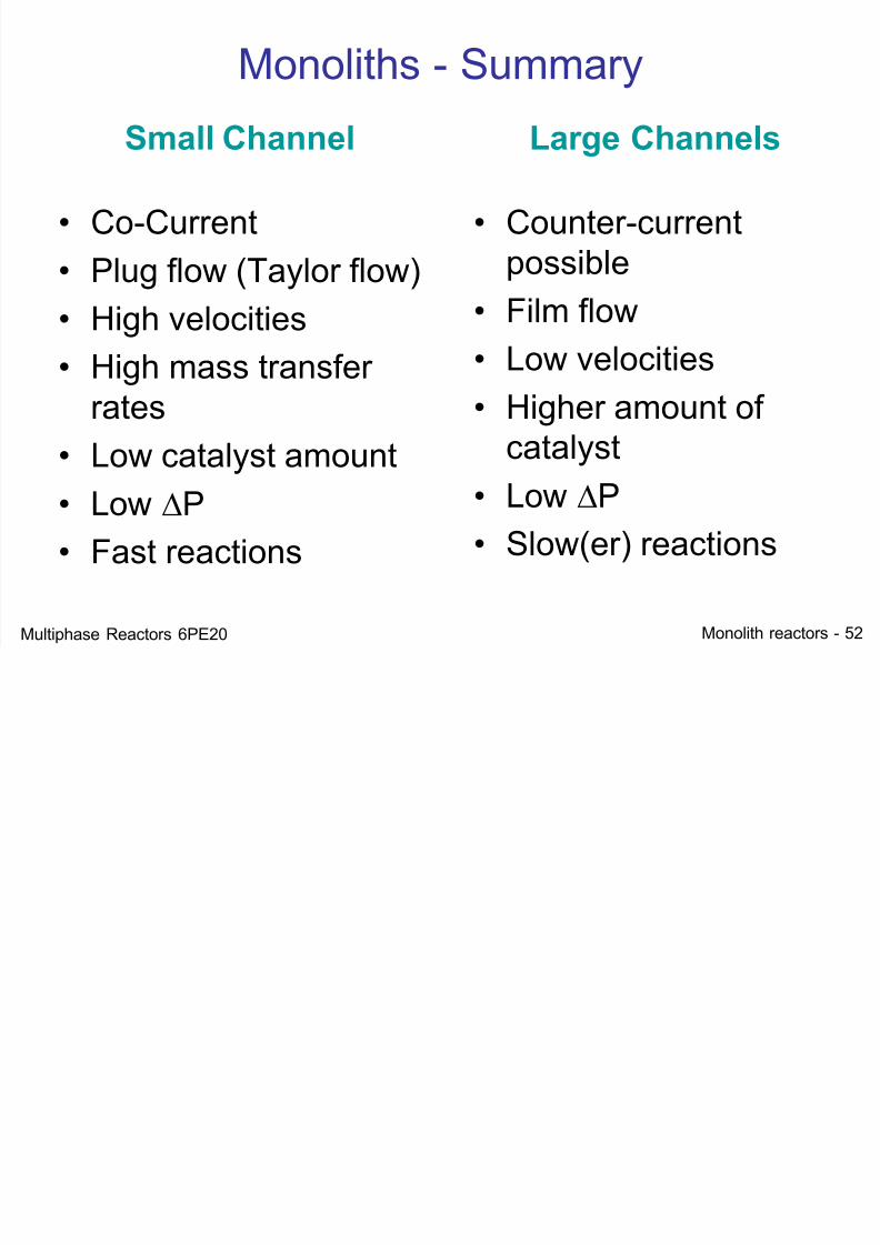
Monoliths - Summary
Small Channel
• Co-Current
• Plug flow (Taylor flow)
• High velocities• High mass transfer
rates
• Low catalyst amount• Low P
• Fast reactions
Large Channels
• Counter-currentpossible
• Film flow• Low velocities
• Higher amount of
catalyst• Low P
• Slow(er) reactions