martinlogan monolith iii manual
TRANSCRIPT

The Monolith III Speaker System
User's Manual
Page2 Monolith III User's Manual
Introduction
Installation in Brief
Monolith III Specifications
History
Connection
IIIp Connection
IIIx Connection
IIIx Operation
IIIx Technical Description
Room Acoustics
Placement
General Information
The Electrostatic Concept
Martin-Logan Exclusives
Questions
Troubleshooting
Glossary
Contents
Your Martin-Logan speakers areprovided with automatic Limited 90Day Warranty coverage.
You have the option, at no additionalcharge, to receive Limited 3 YearWarranty coverage. To obtain Limited 3Year Warranty coverage you need onlycomplete and return the Certificate ofRegistration that was included withyour speakers to Martin-Logan, within30 days of purchase.
If you did not receive a Certificate ofRegistration with your speakers, youcannot be assured of having receivednew units. If this is the case, pleasecontact Martin-Logan.
We know you are anxious to listen toyour new speakers. So, to speed youalong, we have provided an Installationin Brief section ahead of the detaileddescriptive information contained inthis manual.
Please read and follow these instruc-tions for installation in brief as youinitially connect your speakers into yoursystem. These instructions areimportant and will prevent you fromexperiencing any delay, frustration, orsystem damage which might occur ina trial-and-error procedure.
The other sections of your User�sManual will explain in detail theoperation of your speakers and thephilosophy applied to their design. Aclear understanding of your speakerswill insure that you obtain maximumperformance and pleasure from thismost exacting transducer.
3
4
5
6
8
9
12
14
16
18
21
23
24
26
28
29
30
Important
Page3Monolith III User's Manual
Introduction
Congratulations, you have invested inone of the world�s premier loudspeakersystems!
The Martin-Logan MONOLITH III repre-sents the culmination of an intensive,dedicated group research programdirected toward establishing a worldclass reference monitor utilizingleading-edge technology, withoutcompromising durability, reliability,craftsmanship, or aesthetic design.
The original Monolith made its officialdebut in June of 1982 at the Interna-tional Consumer Electronics Showwhere it was selected for the prestigousDesign and Engineering Exhibition asone of the most innovative consumerelectronics products of that year. Sincethen, the Monolith has become thespeaker of choice by the most demand-ing musicians, electronics manufactur-ers, and recording studios, as well asthe most discerning critical listeners.
As a result of our continuous researchand development program here atMartin-Logan, we decided that it wastime to incorporate some of our latesttechnologies into the already outstand-ing Monolith. So, in January of 1990 weintroduced the MONOLITH III to themarketplace.
With the MONOLITH III, we have ad-vanced the current state of the art in
many areas of loudspeaker design.Bass response has better extension,superior impact and improved defini-tion, high frequency response also hasbetter extension and is much morenatural in character. Much effort wasspent on minimizing all diffractive orreflective surfaces. This has improvedoverall transparency and image quality.
In addition, a great amount of energywas spent on the interface between theelectrostatic element and the woofer,with astonishing results. The fruit of thislabor has brought us the passive IIIpINTERFACE and the superior electronicIIIx CROSSOVER. With either of these twodevices, the transition from the electro-static element to the woofer becomesinvisible and an unbelieveable continu-ity of sound prevails. With the IIIxCROSSOVER another veil is lifted andyou are brought even closer to themusical truth. Dynamic informationsuddenly becomes frightening. Powerhandling and system efficiency areenhanced as well.
Like the original Monoliths, all materialsin your new MONOLITH III speakers areof the highest quality to provide years ofenduring enjoyment and deepeningrespect. All trim pieces are constructedfrom selected hardwoods. They arethen grain and color matched and finallyhand finished. The cabinetry is con-structed from a special high-density
hardwood powderboard for structuralintegrity and is finished with a durableand attractive leatherette.
Through rigorous testing, the curvilinearelectrostatic panel manufactured andused by Martin-Logan has proven itselfto be one of the most durable andreliable transducers available today.Fabricated from a specially tooled, high-grade steel, the panel is then coatedwith a special high dielectric nylon/Delrin based polymer that is applied viaa proprietary electrostatic depositionprocess. This panel assembly housesa membrane 0.0005 of an inch thick!Ruggedly constructed and insulated, asmuch as 200 watts of continuouspower has driven the MONOLITH III'senergized diaphragm into massiveexcursions with no deleterious effects.
We again thank you for purchasing theMONOLITH III. By following the Installa-tion in Brief instructions you mayconnect them to your system, sit back,relax, and enjoy this most exactingtransducer. It has been designed andconstructed to give you years of trouble-free listening enjoyment.
Happy Listening!
Page4 Monolith III User's Manual
We know you are eager to hearyour new MONOLITH III loudspeak-ers, so this section is provided toallow fast and easy set up. Onceyou have them operational, pleasetake the time to read, in depth, therest of the information in thismanual. It will give you perspectiveon how to obtain the best possibleperformance from this mostexacting transducer.
If you should experience anydifficulties in the set-up or opera-tion of your MONOLITH III speakersplease refer to the Room Acoustics,Placement or Connection sectionof this manual.
Should you encounter a persistentproblem that cannot be resolved,please contact your AuthorizedMartin-Logan dealer. He willprovide you with the appropriatetechnical analysis to alleviate thesituation.
Step 1: PlacementStep 1: PlacementStep 1: PlacementStep 1: PlacementStep 1: Placement
Place each Monolith at least two feet from any wall and slightly angle themtoward your listening area. This is a good place to start. Please refer to theRoom Acoustics and Placement sections of this manual for more details.
Step 2: PStep 2: PStep 2: PStep 2: PStep 2: Power Connection (Aower Connection (Aower Connection (Aower Connection (Aower Connection (AC)C)C)C)C)
Martin-Logan Monoliths require AC power to energize their electrostatic cells.Using the AC power cords provided, plug them in, making sure that you havemade a firm connection, first to the AC power receptacle on the rear panel ofthe speaker and then to the wall outlet. Extension cords may be used, ifnecessary, since the AC power requirement of the Monolith is extremely small.
Step 3: Signal ConnectionStep 3: Signal ConnectionStep 3: Signal ConnectionStep 3: Signal ConnectionStep 3: Signal Connection
WARNING !WARNING !WARNING !WARNING !WARNING !Turn your amplifier off before making or breaking any signal connections!
The chassis is earth grounded and can present a short circuit to youramplifier if contact is made!
Installation in Brief
Use the best speaker cables you can! 16 gauge zip-cord is the minimum youshould use, and higher quality cables, available from your specialty dealer, arerecommended and will give you superior performance! Spade or bananaconnectors are suggested for optimum contact and ease of installation.
Be consistent when connecting speaker leads to the terminals on the back ofthe MONOLITH III: take great care to assign the same color to the (+) terminal onboth the left and right channels. If bass is nonexistent and you cannot discern atight, coherent image, reverse the (+) and (-) leads on one side to bring thesystem into proper polarity. Attach your speaker cables to the Amplifier Signalinput section of the IIIp INTERFACE if you have the MONOLITH IIIp or directly to theappropriate Signal Input section on the back of the MONOLITH III if you are usingthe MONOLITH IIIx CROSSOVER. Please refer to the appropriate Connectionsection of this manual for further details and instructions.
Step 4: Listen and EnjoyStep 4: Listen and EnjoyStep 4: Listen and EnjoyStep 4: Listen and EnjoyStep 4: Listen and Enjoy
Now, you may turn on your system and enjoy!
Page5Monolith III User's Manual
Monolith III Specifications
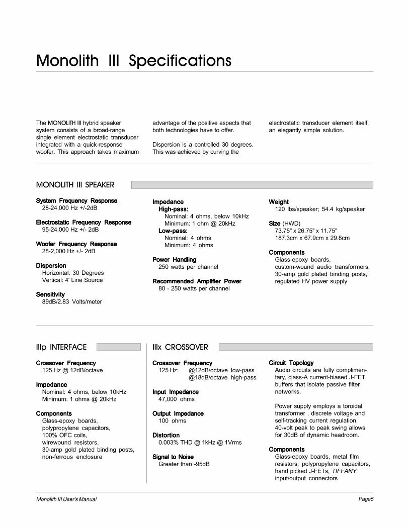
The MONOLITH III hybrid speakersystem consists of a broad-rangesingle element electrostatic transducerintegrated with a quick-responsewoofer. This approach takes maximum
advantage of the positive aspects thatboth technologies have to offer.
Dispersion is a controlled 30 degrees.This was achieved by curving the
electrostatic transducer element itself,an elegantly simple solution.
ImpedanceImpedanceImpedanceImpedanceImpedanceHigh-pass:High-pass:High-pass:High-pass:High-pass:
Nominal: 4 ohms, below 10kHzMinimum: 1 ohm @ 20kHz
Low-pass:Low-pass:Low-pass:Low-pass:Low-pass:Nominal: 4 ohmsMinimum: 4 ohms
Power HandlingPower HandlingPower HandlingPower HandlingPower Handling250 watts per channel
Recommended Amplifier PowerRecommended Amplifier PowerRecommended Amplifier PowerRecommended Amplifier PowerRecommended Amplifier Power80 - 250 watts per channel
MONOLITH III SPEAKER
System Frequency ResponseSystem Frequency ResponseSystem Frequency ResponseSystem Frequency ResponseSystem Frequency Response28-24,000 Hz +/-2dB
Electrostatic Frequency ResponseElectrostatic Frequency ResponseElectrostatic Frequency ResponseElectrostatic Frequency ResponseElectrostatic Frequency Response95-24,000 Hz +/- 2dB
Woofer Frequency ResponseWoofer Frequency ResponseWoofer Frequency ResponseWoofer Frequency ResponseWoofer Frequency Response28-2,000 Hz +/- 2dB
DispersionDispersionDispersionDispersionDispersionHorizontal: 30 DegreesVertical: 4' Line Source
SensitivitySensitivitySensitivitySensitivitySensitivity89dB/2.83 Volts/meter
WeightWeightWeightWeightWeight120 lbs/speaker; 54.4 kg/speaker
Size Size Size Size Size (HWD)73.75" x 26.75" x 11.75"187.3cm x 67.9cm x 29.8cm
ComponentsComponentsComponentsComponentsComponentsGlass-epoxy boards,custom-wound audio transformers,30-amp gold plated binding posts,regulated HV power supply
IIIx CROSSOVER
Crossover FrequencyCrossover FrequencyCrossover FrequencyCrossover FrequencyCrossover Frequency125 Hz: @12dB/octave low-pass
@18dB/octave high-pass
Input ImpedanceInput ImpedanceInput ImpedanceInput ImpedanceInput Impedance47,000 ohms
Output ImpedanceOutput ImpedanceOutput ImpedanceOutput ImpedanceOutput Impedance100 ohms
DistortionDistortionDistortionDistortionDistortion0.003% THD @ 1kHz @ 1Vrms
Signal to NoiseSignal to NoiseSignal to NoiseSignal to NoiseSignal to NoiseGreater than -95dB
IIIp INTERFACE
Crossover FrequencyCrossover FrequencyCrossover FrequencyCrossover FrequencyCrossover Frequency125 Hz @ 12dB/octave
ImpedanceImpedanceImpedanceImpedanceImpedanceNominal: 4 ohms, below 10kHzMinimum: 1 ohms @ 20kHz
ComponentsComponentsComponentsComponentsComponentsGlass-epoxy boards,polypropylene capacitors,100% OFC coils,wirewound resistors,30-amp gold plated binding posts,non-ferrous enclosure
Circuit TopologyCircuit TopologyCircuit TopologyCircuit TopologyCircuit TopologyAudio circuits are fully complimen-tary, class-A current-biased J-FETbuffers that isolate passive filternetworks.
Power supply employs a toroidaltransformer , discrete voltage andself-tracking current regulation.40-volt peak to peak swing allowsfor 30dB of dynamic headroom.
ComponentsComponentsComponentsComponentsComponentsGlass-epoxy boards, metal filmresistors, polypropylene capacitors,hand picked J-FETs, TIFFANYinput/output connectors

Page6 Monolith III User's Manual
In the late 1800�s, any loudspeaker wasconsidered exotic. Today, most of ustake the wonders of sound reproductionfor granted.
It was 1880 before Thomas Edison hadinvented the first phonograph. This wasa horn-loaded diaphragm that wasexcited by a playback stylus. In 1898, SirOliver Lodge invented a cone loud-speaker, which he referred to as a�bellowing telephone�, that was verysimilar to the conventional coneloudspeaker drivers that we know today.However, Lodge had no intention for hisdevice to reproduce music, because in1898 there was no way to amplify anelectrical signal! As a result, hisspeaker had nothing to offer over theacoustical gramophones of the period.It was not until 1906 that Dr. LeeDeForrest invented the triode vacuumtube. Before this , an electrical signalcould not be amplified. The loud-speaker, as we know it today, shouldhave ensued then, but it did not.Amazingly, it was almost twenty yearsbefore this would occur.
In 1921, the electrically cut phonographrecord became a reality. This method ofrecording was far superior to themechanically cut record and pos-sessed almost 30 dB of dynamicrange. The acoustical gramophonecouldn't begin to reproduce all of theinformation on this new disc. As aresult, further developments in loud-speakers were needed to cope withthis amazing new recording medium.
By 1923, Bell Telephone Laboratoriesmade the decision to develop acomplete musical playback systemconsisting of an electronic phonograph
and loudspeaker to take advantage ofthe new recording medium. Bell Labsassigned the project to two youngengineers, C.W. Rice and E.W. Kellogg.
Rice and Kellogg had a well equippedlaboratory at their disposal. This labpossessed a vacuum tube amplifierwith an unheard of 200 watts, a largeselection of the new electrically cutphonograph records and a variety ofloudspeaker prototypes that Bell Labshad been collecting over the pastdecade. Among these were Lodge�scone, a speaker that used compressedair, a corona discharge (plasma)speaker, and an electrostatic speaker.
After a short time, Rice and Kellogg hadnarrowed the field of �contestants�down to the cone and the electrostat.The outcome would dictate the way thatfuture generations would refer toloudspeakers as being either �conven-tional�, or �exotic�.
Bell Laboratory�s electrostat wassomething to behold. This enormousbipolar speaker was as big as a door.The diaphragm, which was beginningto rot, was made of the membrane of apigs intestine that was covered with finegold leaf to conduct the audio signal.
When Rice and Kellogg began playingthe new electrically cut records throughthe electrostat, they were shocked andimpressed. The electrostat performedsplendidly. They had never heardinstrumental timbres reproduced withsuch realism. This system soundedlike real music rather than the honking,squawking rendition of the acousticgramophone. Immediately, they knewthey were on to something big. The
acoustic gramophone was destined tobecome obsolete.
Due to Rice and Kelloggs enthusiasm,they devoted a considerable amount oftime researching the electrostaticdesign. However, they soon encoun-tered the same difficulties that evenpresent designers face; planar speak-ers require a very large surface area toreproduce the lower frequencies of theaudio spectrum. Because the manage-ment at Bell Labs considered largespeakers unacceptable, Rice andKelloggs work on electrostatics wouldnever be put to use for a commercialproduct. Reluctantly, they advised theBell management to go with the cone.For the next thirty years the electrostaticdesign lay dormant.
During the Great Depression of the1930's, consumer audio almost died.The new electrically amplified loud-speaker never gained acceptance, asmost people continued to use their oldVictrola-style acoustic gramophones.Prior to the end of World War II, con-sumer audio saw little, if any, progress.However, during the late 1940's, audioexperienced a great rebirth. Suddenlythere was tremendous interest in audioproducts and with that, a great demandfor improved audio components. Nosooner had the cone become estab-lished than it was challenged byproducts developed during this newrebirth.
In 1947, Arthur Janszen, a young Navalengineer, took part in a research projectfor the Navy. The Navy wasinterested in developing a betterinstrument for testing microphonearrays. The test instrument needed an
History
Page7Monolith III User's Manual
extremely accurate speaker, butJanszen found that the cone speakersof the period were too nonlinear inphase and amplitude response to meethis criteria. Janszen believed thatelectrostats were inherently more linearthan cones, so he built a model using athin plastic diaphragm treated with aconductive coating. This modelconfirmed Janszen's beliefs, for itexhibited remarkable phase andamplitude linearity.
Janszen was so excited with the resultsthat he continued research on theelectrostatic speaker on his own time.He soon thought of insulating thestators to prevent the destructive effectsof arcing. By 1952 he had an electro-static tweeter element ready forcommercial production. This newtweeter soon created a sensationamong American audio hobbyists.Since Janszen's tweeter element waslimited to high frequency reproduction, itoften found itself used in conjunctionwith woofers, most notably, woofersfrom Acoustic Research. Thesesystems were highly regarded by allaudio enthusiasts.
As good as these systems were, theywould soon be surpassed by anotherelectrostatic speaker.
In 1955, Peter Walker published threearticles on electrostatic loudspeakerdesign in Wireless World, a Britishelectronics magazine. In these articlesWalker demonstrated the benefits of theelectrostatic loudspeaker. He explainedthat electrostatics permit the use ofdiaphragms that are low in mass, largein area, and uniformly driven over their
surfaces by electrostatic forces. Due tothese characteristics, electrostats havethe inherent ability to produce a widebandwidth, flat frequency response withdistortion products being no greaterthan the electronics driving them.
By 1956 Walker backed up his articlesby introducing a consumer product, thenow famous Quad ESL. This speakerimmediately set a standard of perform-ance for the audio industry due to itsincredible accuracy. However, in actualuse the Quad had a few problems. Itcould not play very loud, it had poorbass performance, it presented adifficult load that some amplifiers didnot like, its dispersion was verydirectional, and its power handling waslimited to around 70 watts. As a result,many people continued to use boxspeakers with cones.
In the early 1960's Arthur Janszenjoined forces with the KLH loudspeakercompany and together they introducedthe KLH 9. Due to the large size of theKLH 9, it did not have as many limita-tions as the Quad. The KLH 9 couldplay markedly louder and lower infrequency than the Quad ESL. Thus arivalry was born.
Janszen continued to develop electro-static designs. He was instrumental inthe design of the Koss Model One, theAcoustech, and the Dennesen speak-ers. Roger West, the chief designer ofthe JansZen Corporation became thepresident of Sound Lab. When JansZenCorporation was sold, the RTRloudspeaker company bought half ofthe production tooling. This tooling wasused to make the electrostatic panels
for the Servostatic, a hybrid electrostaticsystem that was Infinity's first speakerproduct. Other companies soonfollowed; each with their own uniqueapplications of the technology. Theseinclude Acoustat, Audiostatic, Beverage,Dayton Wright, Sound Lab, and Stax toname a few.
Electrostatic speakers have pro-gressed and prospered because theyactually do what Peter Walker claimedthey would. The limitations and prob-lems experienced in the past were notinherent to the electrostatic concept.They were related to the applications ofthese concepts.
Today, these limitations have beenaddressed. Advancements in materialsdue to the U.S. space program givedesigners the ability to harness thesuperiority of the electrostatic principle.Todays electrostats use advancedinsulation techniques or provideprotection circuitry. The poor dispersionproperties of early models have beenaddressed by using delay lines,acoustical lenses, multiple panel arraysor, as in our own products, by curvingthe diaphragm. Power handling andsensitivity have been increased.
These developments allow the con-sumer the opportunity to own thehighest performance loudspeakerproducts ever built. It's too bad Rice andKellogg were never able to see just howfar the technology would be taken.

Page8 Monolith III User's Manual
AC Power ConnectionAC Power ConnectionAC Power ConnectionAC Power ConnectionAC Power Connection
Electrostatic speakers use an internal power supply toenergize their electrostatic elements with high-voltage DC(low current). As such, they must be connected to an ACwall outlet. For this reason we have provided your speakerswith the proper IEC standard power cords. These cordsshould be firmly inserted into the AC power receptacles onthe rear connection panel of the speakers, then to anyconvenient AC wall outlet. Extension cords may be used, ifnecessary, since the AC power requirement of the speakeris extremely small (less than 2.5 watts).
We do not recommend the use of "super cords", as manyof these designs eliminate the ground prong of the maleplug and therefore do not follow IEC convention standards.If proper plugs are fitted, then the choice is up to you.
Your Martin-Logan speakers have been designed toremain on continuously and should remain connected to acontinuous AC power source. As mentioned earlier, powerconsumption of the MONOLITH III is very small and the lifeexpectancy of its components will not be reduced bycontinuous operation.
The power cord should not be installed, removed,The power cord should not be installed, removed,The power cord should not be installed, removed,The power cord should not be installed, removed,The power cord should not be installed, removed,or left detached from the speaker while the otheror left detached from the speaker while the otheror left detached from the speaker while the otheror left detached from the speaker while the otheror left detached from the speaker while the other
end is connected to an AC wall outlet.end is connected to an AC wall outlet.end is connected to an AC wall outlet.end is connected to an AC wall outlet.end is connected to an AC wall outlet.
Your Martin-Logan speakers are wired for the powerservice supplied in the country of original consumer saleunless manufactured on special order. The AC powerrating applicable to a particular unit is specified both on thepacking carton and on the serial number plate attached tothe speaker.
If you remove your Martin-Logan speakers from the countryof original sale, be certain that AC power supplied in anysubsequent location is suitable before connecting andoperating the speakers. Substantially impaired perform-ance or severe damage may occur to a Martin-Loganspeaker if operation is attempted from an incorrect ACpower source.
If your home is not equipped with three-prong wall outlets,you may use �cheater� plugs to connect the speakers to ACpower. However, please make certain that you connect thegrounding wire or tab of the plug to a ground. These maybe obtained at your dealer or any hardware department.
Signal ConnectionSignal ConnectionSignal ConnectionSignal ConnectionSignal Connection
Use the best speaker cables you can! The length and typeof speaker cable used in your system will have an audibleeffect. Under no circumstance should a wire of gaugehigher (thinner) than #16 be used. In general, the longerthe length used, the greater the necessity of a lower gauge,and the lower the gauge, the better the sound, with dimin-ishing returns setting in around #8 to #12.
A variety of speaker cables are now available whosemanufacturers claim better performance than with standardheavy gauge wire. We have verified this in some cases,and the improvements available are often more noticeablethan the differences between wires of different gauge.
We would also recommend, if possible, that short runs ofspeaker cable connect the power amplifier(s) and speak-ers and that high quality long interconnect cables be usedto connect the preamplifier and power amplifier. Thisresults in the power amplifiers being close to the speakers,which may be practically or cosmetically difficult, but if thelength of the speaker cables can be reduced to a fewmeters, sonic advantages may be obtained. The effects ofcables may be masked if the equipment is not of thehighest quality.
Connections are done at the SIGNAL INPUT section on therear electronics panel of the MONOLITH III. Use spade orbanana connectors for optimum contact and ease ofinstallation. Make certain that all your connections areclean, tight and positive.
Be consistent when connecting the speaker cables to theSIGNAL INPUT terminals. Take care to assign the same colorcable lead to the (+) terminal on both the left and rightchannel speakers. If bass is nonexistent and you cannotdiscern a tight, coherent image, you probably need toreverse the (+) and (-) leads on one speaker to bring thesystem into proper polarity.
The MONOLITH IIIp INTERFACE provides you with threedifferent methods for connecting the MONOLITH III to youraudio system, while the superior MONOLITH IIIx CROSSOVERuses active bi-amplification.
Connection
Page9Monolith III User's Manual
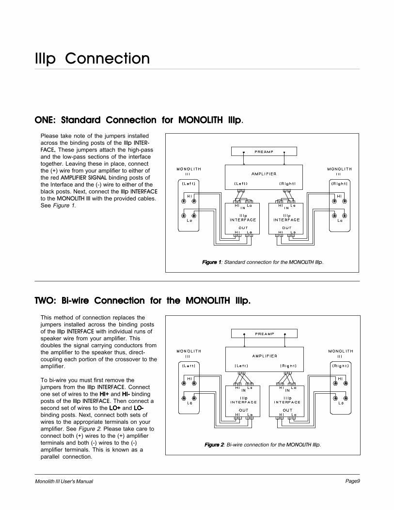
Please take note of the jumpers installedacross the binding posts of the IIIp INTER-FACE..... These jumpers attach the high-passand the low-pass sections of the interfacetogether. Leaving these in place, connectthe (+) wire from your amplifier to either ofthe red AMPLIFIER SIGNAL binding posts ofthe Interface and the (-) wire to either of theblack posts. Next, connect the IIIp INTERFACEto the MONOLITH III with the provided cables.See Figure 1.
This method of connection replaces thejumpers installed across the binding postsof the IIIp INTERFACE with individual runs ofspeaker wire from your amplifier. Thisdoubles the signal carrying conductors fromthe amplifier to the speaker thus, direct-coupling each portion of the crossover to theamplifier.
To bi-wire you must first remove thejumpers from the IIIp INTERFACE. Connectone set of wires to the HI+HI+HI+HI+HI+ and HI-HI-HI-HI-HI- bindingposts of the IIIp INTERFACE. Then connect asecond set of wires to the LO+LO+LO+LO+LO+ and LO-LO-LO-LO-LO-binding posts. Next, connect both sets ofwires to the appropriate terminals on youramplifier. See Figure 2. Please take care toconnect both (+) wires to the (+) amplifierterminals and both (-) wires to the (-)amplifier terminals. This is known as aparallel connection.
TWO: Bi-wire Connection for the TWO: Bi-wire Connection for the TWO: Bi-wire Connection for the TWO: Bi-wire Connection for the TWO: Bi-wire Connection for the MONOLITH IIIMONOLITH IIIMONOLITH IIIMONOLITH IIIMONOLITH IIIp.p.p.p.p.
IIIp Connection
ONE: Standard Connection for ONE: Standard Connection for ONE: Standard Connection for ONE: Standard Connection for ONE: Standard Connection for MONOLITH IIIMONOLITH IIIMONOLITH IIIMONOLITH IIIMONOLITH IIIppppp.
Figure 1Figure 1Figure 1Figure 1Figure 1: Standard connection for the MONOLITH IIIp.
Figure 2Figure 2Figure 2Figure 2Figure 2: Bi-wire connection for the MONOLITH IIIp.
Page10 Monolith III User's Manual
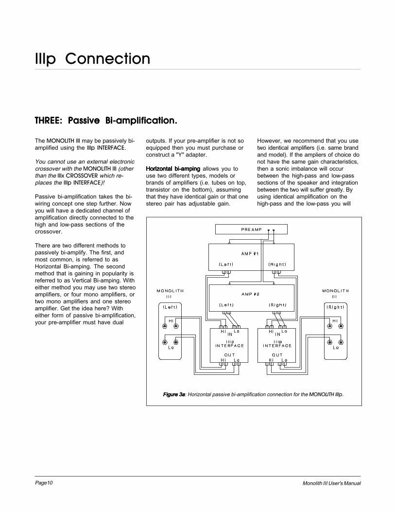
THREE: Passive Bi-amplification.THREE: Passive Bi-amplification.THREE: Passive Bi-amplification.THREE: Passive Bi-amplification.THREE: Passive Bi-amplification.
The MONOLITH III may be passively bi-amplified using the IIIp INTERFACE.
You cannot use an external electroniccrossover with the MONOLITH III (otherthan the IIIx CROSSOVER which re-places the IIIp INTERFACE)!
Passive bi-amplification takes the bi-wiring concept one step further. Nowyou will have a dedicated channel ofamplification directly connected to thehigh and low-pass sections of thecrossover.
There are two different methods topassively bi-amplify. The first, andmost common, is referred to asHorizontal Bi-amping. The secondmethod that is gaining in popularity isreferred to as Vertical Bi-amping. Witheither method you may use two stereoamplifiers, or four mono amplifiers, ortwo mono amplifiers and one stereoamplifier. Get the idea here? Witheither form of passive bi-amplification,your pre-amplifier must have dual
outputs. If your pre-amplifier is not soequipped then you must purchase orconstruct a "Y" adapter.
Horizontal bi-amping Horizontal bi-amping Horizontal bi-amping Horizontal bi-amping Horizontal bi-amping allows you touse two different types, models orbrands of amplifiers (i.e. tubes on top,transistor on the bottom), assumingthat they have identical gain or that onestereo pair has adjustable gain.
However, we recommend that you usetwo identical amplifiers (i.e. same brandand model). If the ampliers of choice donot have the same gain characteristics,then a sonic imbalance will occurbetween the high-pass and low-passsections of the speaker and integrationbetween the two will suffer greatly. Byusing identical amplification on thehigh-pass and the low-pass you will
IIIp Connection
Figure 3aFigure 3aFigure 3aFigure 3aFigure 3a: Horizontal passive bi-amplification connection for the MONOLITH IIIp.
Page11Monolith III User's Manual
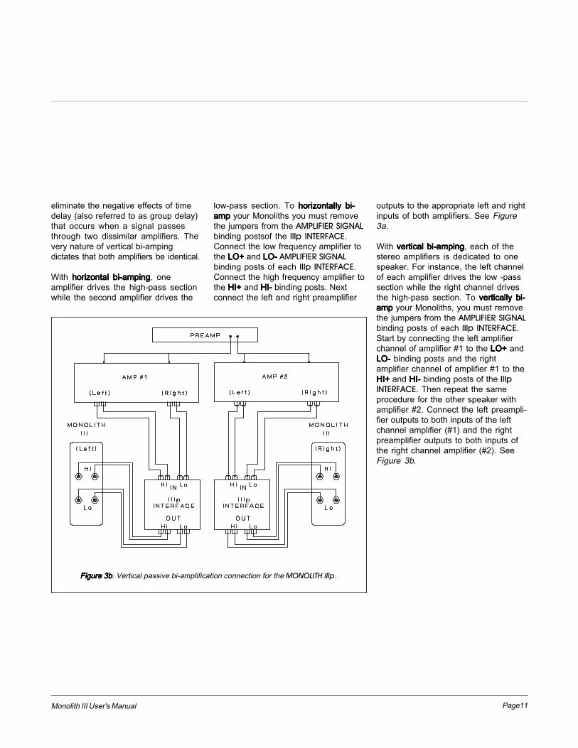
eliminate the negative effects of timedelay (also referred to as group delay)that occurs when a signal passesthrough two dissimilar amplifiers. Thevery nature of vertical bi-ampingdictates that both amplifiers be identical.
With horizontal bi-ampinghorizontal bi-ampinghorizontal bi-ampinghorizontal bi-ampinghorizontal bi-amping, oneamplifier drives the high-pass sectionwhile the second amplifier drives the
low-pass section. To horizontally bi-horizontally bi-horizontally bi-horizontally bi-horizontally bi-amp amp amp amp amp your Monoliths you must removethe jumpers from the AMPLIFIER SIGNALbinding postsof the IIIp INTERFACE.Connect the low frequency amplifier tothe LO+LO+LO+LO+LO+ and LO-LO-LO-LO-LO- AMPLIFIER SIGNALbinding posts of each IIIp INTERFACE.Connect the high frequency amplifier tothe HI+HI+HI+HI+HI+ and HI-HI-HI-HI-HI- binding posts. Nextconnect the left and right preamplifier
outputs to the appropriate left and rightinputs of both amplifiers. See Figure3a.
With vertical bi-ampingvertical bi-ampingvertical bi-ampingvertical bi-ampingvertical bi-amping, each of thestereo amplifiers is dedicated to onespeaker. For instance, the left channelof each amplifier drives the low -passsection while the right channel drivesthe high-pass section. To vertically bi-vertically bi-vertically bi-vertically bi-vertically bi-amp amp amp amp amp your Monoliths, you must removethe jumpers from the AMPLIFIER SIGNALbinding posts of each IIIp INTERFACE.Start by connecting the left amplifierchannel of amplifier #1 to the LO+LO+LO+LO+LO+ andLO-LO-LO-LO-LO- binding posts and the rightamplifier channel of amplifier #1 to theHI+HI+HI+HI+HI+ and HI-HI-HI-HI-HI- binding posts of the IIIpINTERFACE. Then repeat the sameprocedure for the other speaker withamplifier #2. Connect the left preampli-fier outputs to both inputs of the leftchannel amplifier (#1) and the rightpreamplifier outputs to both inputs ofthe right channel amplifier (#2). SeeFigure 3b.
Figure 3bFigure 3bFigure 3bFigure 3bFigure 3b: Vertical passive bi-amplification connection for the MONOLITH IIIp.
Page12 Monolith III User's Manual
IntroductionIntroductionIntroductionIntroductionIntroduction
The MONOLITH IIIx system utilizes theelectronic IIIx CROSSOVER whichincorporates technology developed forour STATEMENT SYSTEM CROSSOVER.Use of the MONOLITH IIIx CROSSOVERwill result in substantial improvementsin all aspects of your system's perform-ance. Bass will be more extended withmore impact and control. Special basscontour controls allow you to tailor thebass response to suit your particularroom environment or listening tastes.The crossover region between thewoofer and electrostatic panel isoptimized, thus making the systemblend much more homogeneous.Highs are much more extended,detailed and effortless. The systembecomes much more dynamic withless strain. To understand why thisoccurs, we need to look at the differ-ences between a single amplifiedsystem versus a properly interfaced bi-amplified system.
In a single amplified system, the leftand right full-bandwidth signals passfrom the preamplifier to a stereo poweramplifier (or two mono amplifiers) andthen to the loudspeaker's crossover,unchanged (we hope) except foramplitude. Once these signals reach
IIIx Connection
the crossover of the speaker they aredivided into high and low frequencysignals. The lower frequency signalsare then directed to the woofers, whilethe high frequencies are routed to theelectrostatic panels. This is known as ahigh-level passive crossover. Thismeans that the frequency division of thesignal is done after the power amplifierat high power (several volts) by meansof passive components (capacitors,resistors, inductors and transformers).
When bi-amplifying with the MONOLITHIIIx CROSSOVER, the right and left full-bandwidth signals are divided intoseparate high and low frequencysignals after the pre-amplifier by meansof an active electronic crossover. Thesesignals are then fed to dedicated highand low frequency amplifiers. This isreferred to as a low-level active cross-over, because all frequency division ofthe signal is done at line level at verylow power (millivolts) with activecomponents (transistors).
This configuration has several advan-tages. With the frequency division of thesignal done prior to amplification, eachamplifier has only to contend with
frequencies of a narrow bandwidth,thus it cannot combine high and lowfrequency signals and produce sumand difference by-products (intermodu-lation distortion or IM). For example, toreproduce deep bass such as an organtone or kick drum, very high power(current) is needed. Since the lowfrequencies have their own dedicatedamplifier, this demand for low frequencypower will not affect the ability of thehigh frequency amplifier to perform itsfunction normally, whereas if allfrequencies were reproduced by thesame amplifier, its power supply mighttemporarily be depleted by the deepbass passage, causing dynamiccompression or clipping of the highfrequency material.
Another added benefit of bandwidthlimiting an amplifier, particularly thehigh frequency amplifier, is the slightincrease in dynamic power output thatoccurs. The amplifier does not have towork as hard due to the reduction in thebandwidth amplification requirements.Therefore the amplifier can apply morepower into the smaller frequency region.
WarningsWarningsWarningsWarningsWarnings
To prevent fire or shock hazard, do notexpose the MONOLITH IIIx CROSSOVERto rain or moisture.
Hazardous voltage potentials exist inthis crossover. Do not operate with thecover removed. There are no userserviceable components inside. Referservicing to your authorized Martin-Logan dealer only.
PackagingPackagingPackagingPackagingPackaging
Please save all packaging and store ina dry place away from potential firehazard. Your MONOLITH IIIx CROSSOVERis a precision electronic instrument andshould be packaged properly in itsoriginal carton any time shipment isnecessary. We hope that you will never
have occasion to return your unit to ourfactory for service, but in the event thatservicing should prove necessary, orother occasion requiring shipmentoccurs, the original packaging willprotect your unit from unnecessarydamage or delay.

Page13Monolith III User's Manual
AAAAAC PC PC PC PC Power Connectionower Connectionower Connectionower Connectionower Connection
Plug in AC mains only after allPlug in AC mains only after allPlug in AC mains only after allPlug in AC mains only after allPlug in AC mains only after allsignal connections have beensignal connections have beensignal connections have beensignal connections have beensignal connections have been
made and you have verified thatmade and you have verified thatmade and you have verified thatmade and you have verified thatmade and you have verified thatboth amplifiers are switched off.both amplifiers are switched off.both amplifiers are switched off.both amplifiers are switched off.both amplifiers are switched off.
We have provided your MONOLITH IIIxCROSSOVER with the proper IECstandard 3-conductor power cords with3-prong grounding plug. This cordshould be firmly inserted into the ACpower receptacle located on the rearpanel of the crossover, then to any
Signal ConnectionSignal ConnectionSignal ConnectionSignal ConnectionSignal Connection
Insert your pre-amps' output cables intothe crossovers' INPUT jacks, thenconnect your low-pass amplifiers' inputcables to the crossovers' LOW OUT-PUT jacks, and your high-pass amplifi-ers' input cables to theHIGH OUTPUT jacks.
Plug in AC mains only after allPlug in AC mains only after allPlug in AC mains only after allPlug in AC mains only after allPlug in AC mains only after allsignal connections have beensignal connections have beensignal connections have beensignal connections have beensignal connections have been
made and you have verified thatmade and you have verified thatmade and you have verified thatmade and you have verified thatmade and you have verified thatboth amplifiers are switched off.both amplifiers are switched off.both amplifiers are switched off.both amplifiers are switched off.both amplifiers are switched off.
Next, connect the speaker leads fromthe high-pass amplifier to the HISIGNAL INPUTS on the back of theMONOLITH III. Then connect the low-pass amplifier to the LO SIGNALINPUTS. Please refer to the pictorialdiagram, Figure 4 , at right.
Figure 4Figure 4Figure 4Figure 4Figure 4: MONOLITH IIIx CROSSOVER connection.
convenient AC wall outlet. For absoluteprotection, do not defeat the power plugground. This provides powerlinegrounding of the MONOLITH IIIx CROSS-OVER chassis and will protect you fromelectrical shock.
We do not recommend the replacementor use of "deluxe" or "super" AC powercords. Many of these designs eliminatethe ground prong of the male plug andtherefore do not follow IEC conventionstandards. As such, they present thepossibility of shock hazard.
Your MONOLITH IIIx CROSSOVER has nopower switch as it has been designedto remain on continuously and shouldremain connected to a continuous ACpower source.
Your crossover is wired for the powerservice supplied in the country oforiginal consumer sale unless manu-factured on special order. The ACpower rating applicable to a particularunit is specified both on the packingcarton and on the serial number plateattached to the crossover.
Page14 Monolith III User's Manual
Crossover SettingsCrossover SettingsCrossover SettingsCrossover SettingsCrossover Settings
Before you do any formal listening,you must set a pair of switches in thecrossover. However, if you are usingidentical amplifiers (i.e. same makeand model) for the high and low-passsections of the Monolith, you may usethe factory settings and skip this step.
On the back panel of the crossoverthere are two cut-outs that allow youto access two red dip switches. Theseswitches adjust the low-pass gain sothat you may balance the gainbetween the high-pass and low-passamplifiers if they have different gaincharacteristics. We have evenenclosed a red "dip stick" tool to assistyou with this procedure.
The following formula will help youcalculate the relative gain of youramplifiers:
Amplifier gain is defined as:
20 log20 log20 log20 log20 log
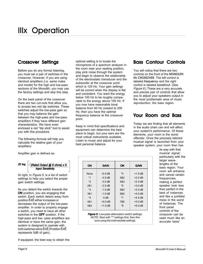
At right, in Figure 5, is a list of switchsettings to help you select the propergain switch settings.
As you detent the switch towards theONONONONON position, you are engaging thatswitch. Each switch detent away fromposition �4� either increases ordecreases the output of the low-passamplifier. In order to properly engagea switch, you need to have all otherswitches in the OFF OFF OFF OFF OFF position. If thehigh-pass and low- pass amplifiers areidentical or have the same gain, thesystem is designed to operate withboth switches set to �4� (Position �4�represents 0dB of gain).
If equipped, the best way to obtain the
(Rated Output @ 8 ohms) x 8(Rated Output @ 8 ohms) x 8(Rated Output @ 8 ohms) x 8(Rated Output @ 8 ohms) x 8(Rated Output @ 8 ohms) x 8 Input Sensitivity Input Sensitivity Input Sensitivity Input Sensitivity Input Sensitivity
IIIx Operation
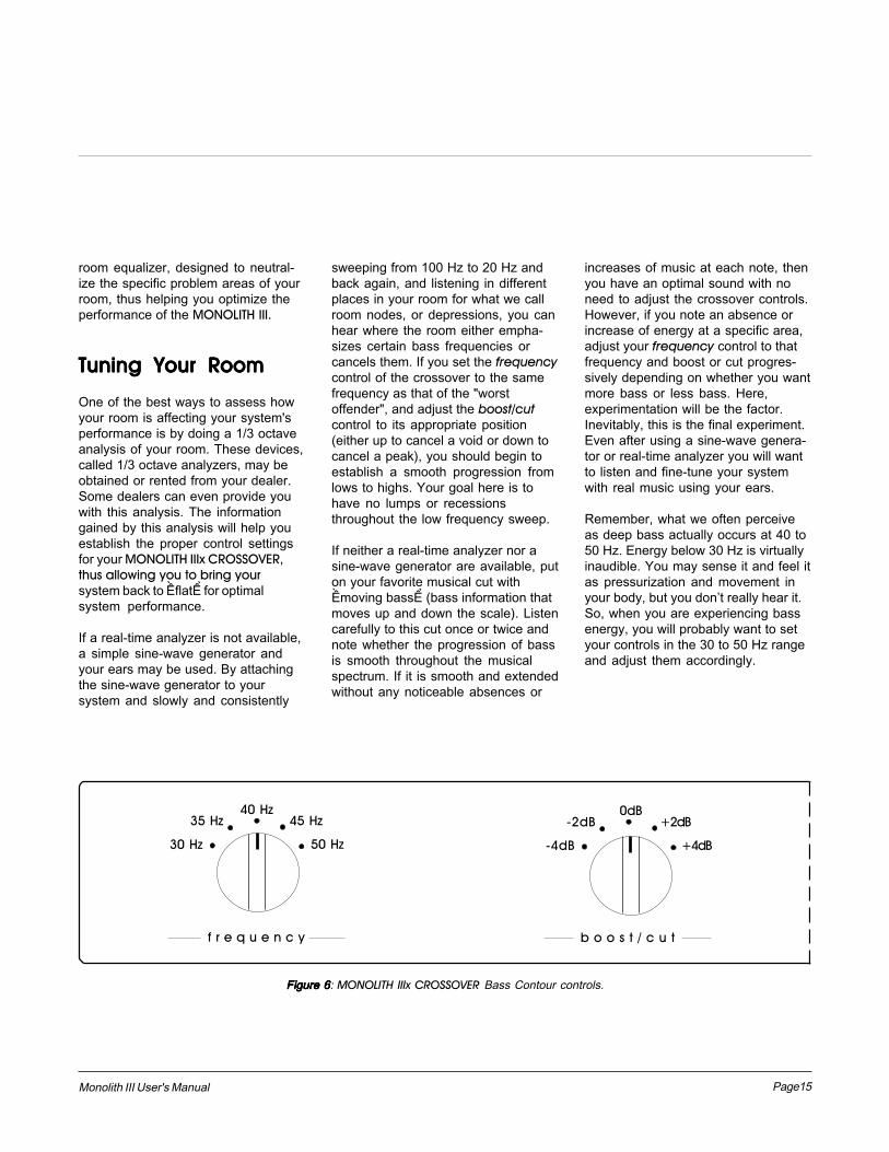
Bass Contour ControlsBass Contour ControlsBass Contour ControlsBass Contour ControlsBass Contour Controls
You will notice that there are twocontrols on the front of the MONOLITHIIIx CROSSOVER. The left control islabeled frequency and the rightcontrol is labeled boost/cut. (SeeFigure 6.) These are a very accurateand precise pair of controls that allowyou to adjust your speakers output inthe most problematic area of musicreproduction; the bass region.
optimal setting is to locate themicrophone of a spectrum analyzer inthe room near your seating position,play pink noise through the systemand begin to observe the relationshipof the electrostatic transducer and thesubwoofer at the crossover pointwhich is 125 Hz. Your gain settingswill be correct when the display is flatand consistent. You want the energybelow 100 Hz to be roughly compa-rable to the energy above 100 Hz. Ifyou now have reasonable tonalbalance from 60 Hz onward to 200Hz, then you have the optimalfrequency balance at the crossoverpoint.
Keep in mind that specifications andequipment can determine the bestplace to begin, but your ears are themost critical instruments available.Listen to music and adjust for yourbest personal balance.
ONONONONON
None*1*2
2&1*3
3&1*4
4&14&2
GAINGAINGAINGAINGAIN
-6.0 dB-4.5 dB-3.0 dB-2.0 dB-1.5 dB-1.0 dB
0 dB+0.5 dB+1.0 dB
ONONONONON
*55&25&3*6
6&36&5*7
7&6*8
GAINGAINGAINGAINGAIN
+1.5 dB+2.0 dB+2.5 dB+3.0 dB+3.5 dB+4.0 dB+4.5 dB+5.0 dB+6.0 dB
Figure 5Figure 5Figure 5Figure 5Figure 5: Low-pass attenuation switch settings.NOTE: Start with "*" settings first, then fine
tune using the intermediate settings.
Your Room and BassYour Room and BassYour Room and BassYour Room and BassYour Room and Bass
Today we are finding that all elementsin the audio chain can and will affectyour system's performance. Of theseelements, your room is the worstoffender. Once the precisely tailoredmusical signal is launched from yourspeaker system, your room then has
its way with thatmusical signal;particularly with thelarger wave-lengths of thebass region. Yourroom will enhanceand cancel certainfrequencies,making a perfectspeaker look lessthan perfect in thebest of instancesand like a jumbledmess in the worstof instances. Thefront panelcontrols of thecrossover can beused much like anaccurate bass/
Page15Monolith III User's Manual
+4dB
35 Hz 45 Hz40 Hz
30 Hz 50 Hz
-2dB 0dB
-4dB
+2dB
f r e q u e n c y b o o s t / c u t
Figure 6Figure 6Figure 6Figure 6Figure 6: MONOLITH IIIx CROSSOVER Bass Contour controls.
room equalizer, designed to neutral-ize the specific problem areas of yourroom, thus helping you optimize theperformance of the MONOLITH III.
Tuning Your RoomTuning Your RoomTuning Your RoomTuning Your RoomTuning Your Room
One of the best ways to assess howyour room is affecting your system'sperformance is by doing a 1/3 octaveanalysis of your room. These devices,called 1/3 octave analyzers, may beobtained or rented from your dealer.Some dealers can even provide youwith this analysis. The informationgained by this analysis will help youestablish the proper control settingsfor your MONOLITH IIIx CROSSOVER,thus allowing you to bring yoursystem back to �flat� for optimalsystem performance.
If a real-time analyzer is not available,a simple sine-wave generator andyour ears may be used. By attachingthe sine-wave generator to yoursystem and slowly and consistently
sweeping from 100 Hz to 20 Hz andback again, and listening in differentplaces in your room for what we callroom nodes, or depressions, you canhear where the room either empha-sizes certain bass frequencies orcancels them. If you set the frequencycontrol of the crossover to the samefrequency as that of the "worstoffender", and adjust the boost/cutcontrol to its appropriate position(either up to cancel a void or down tocancel a peak), you should begin toestablish a smooth progression fromlows to highs. Your goal here is tohave no lumps or recessionsthroughout the low frequency sweep.
If neither a real-time analyzer nor asine-wave generator are available, puton your favorite musical cut with�moving bass� (bass information thatmoves up and down the scale). Listencarefully to this cut once or twice andnote whether the progression of bassis smooth throughout the musicalspectrum. If it is smooth and extendedwithout any noticeable absences or
increases of music at each note, thenyou have an optimal sound with noneed to adjust the crossover controls.However, if you note an absence orincrease of energy at a specific area,adjust your frequency control to thatfrequency and boost or cut progres-sively depending on whether you wantmore bass or less bass. Here,experimentation will be the factor.Inevitably, this is the final experiment.Even after using a sine-wave genera-tor or real-time analyzer you will wantto listen and fine-tune your systemwith real music using your ears.
Remember, what we often perceiveas deep bass actually occurs at 40 to50 Hz. Energy below 30 Hz is virtuallyinaudible. You may sense it and feel itas pressurization and movement inyour body, but you don�t really hear it.So, when you are experiencing bassenergy, you will probably want to setyour controls in the 30 to 50 Hz rangeand adjust them accordingly.
Page16 Monolith III User's Manual
Musical TastesMusical TastesMusical TastesMusical TastesMusical Tastes
An added benefit of the contourcontrols on the IIIx CROSSOVER, isthe ability to adjust your speaker'spersonality to your style of listening.
It is well known that an �audiophile�listening priority is different from that of�rock� or �classic European� listeningorientation. By setting your frequencycontrol to 30 Hz and the boost/cutcontrol to 0dB, you will have what isknown as the "Audiophile setting". Thissetting allows the deepest bassextension and most linear theoreticperformance. Experimenting slightlywith the boost/cut control will give youeither a drier or deeper and moreextended performance. However, if a�rock� orientation is your preference,set the frequency control between 40to 50 Hz with a slight boost, and youwill get more of the emphasizedpercussive effect of rock music. Thelast priority, �classic European�,consists of a dry, clean, very tight bassstructure. It can be accomplished byresetting the frequency control to 30Hz and turning down the boost/cutcontrol. At this point, you will still havedeep and extended bass, but it will beslightly rolled off to give you a very tight,defined performance level.
In the final evaluation, your ears willdetermine where these controlsshould be positioned. They have beenestablished for your flexibility and useand can be used much like an accuratebass/room equalizer. So don't beafraid to experiment and have fun!
IIIx Operation IIIx Technical Description
Theory of OperationTheory of OperationTheory of OperationTheory of OperationTheory of Operation
The audio signal coming from the pre-amplifier of your audio system istypically representitive of a low imped-ance voltage source. There are a fewpreamplifiers, such as older tubedesigns, which may not conform tothis, as they have a much higher outputimpedance. In addition many cablescan change the preamplifiers outputcharacteristics.
In order to assure a high level ofperformance with all types of preampsand cables, the MONOLITH IIIx CROSS-OVER has a high input impedance, lowoutput impedance buffer for its firststage. Futhermore, since there is nosubstitute for isolation to preventvarious filter sections from interactingwith each other (normally the highpass and low pass filters), the MONO-LITH IIIx CROSSOVER has a separatebuffer for the high-pass and the low-pass audio path.
These buffers are designed using twocomplimentary J-FET devices perbuffer, strapped in unity gain, voltagefollower topology. Two additionalbipolar devices are used as currentsources only, enabling the J-FETs tobe completely current biased. Thiscomplimentary J-FET buffer is usedrepeatedly throughout the crossover,except for the output stage whichrequires gain.
In being a dedicated electroniccrossover/equalizer, it is vital to tailorthe system to the needs of thespeaker. Planar speakers have twomain areas of concern: 1) Rear wavecancellation, which causes a decreasein the speaker�s output below 500 Hz,and 2) Primary resonance, which is thefrequency the speaker is tuned to.
Rear wave cancellation requirescorrective equalization beginning at500 Hz and increasing to roughly 12dBat 100 Hz. Primary resonance affectsthis response as well, because thespeaker is effectively out of control atprimary resonance. A notch filter workswell to negate the effects of thistypically 12dB resonance. The decisionof resonance tuning and rear wavecancellation compensation, combinedin balance with the high frequency roll-off point, is a system decision basedon the sonic properties of the speakeritself.
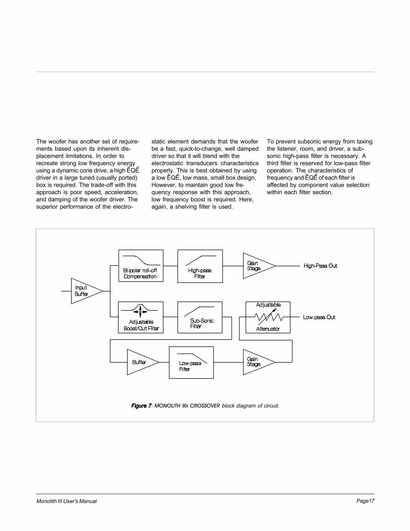
The MONOLITH IIIx CROSSOVER's high-pass pathway utilizes three separatefilter sections; one for raising energybetween 100 Hz and 500 Hz, empha-sizing 100 Hz (referred to as a shelvingfilter), another for decreasing energy atthe speaker resonance (notch filter)and a third high-pass filter.
Page17Monolith III User's Manual
To prevent subsonic energy from taxingthe listener, room, and driver, a sub-sonic high-pass filter is necessary. Athird filter is reserved for low-pass filteroperation. The characteristics offrequency and �Q� of each filter isaffected by component value selectionwithin each filter section.
The woofer has another set of require-ments based upon its inherent dis-placement limitations. In order torecreate strong low frequency energyusing a dynamic cone drive, a high �Q�driver in a large tuned (usually ported)box is required. The trade-off with thisapproach is poor speed, acceleration,and damping of the woofer driver. Thesuperior performance of the electro-
static element demands that the wooferbe a fast, quick-to-change, well dampeddriver so that it will blend with theelectrostatic transducers characteristicsproperly. This is best obtained by usinga low �Q�, low mass, small box design.However, to maintain good low fre-quency response with this approach,low frequency boost is required. Here,again, a shelving filter is used.
Figure 7Figure 7Figure 7Figure 7Figure 7: MONOLITH IIIx CROSSOVER block diagram of circuit.
Page18 Monolith III User's Manual
Your RoomYour RoomYour RoomYour RoomYour Room
This is one of those areas that requiresa little background to understand andsome time and experimentation toobtain the best performance from yoursystem.
Your room is actually a component andan important part of your system. Thiscomponent is a very large variable andcan dramatically add to, or subtractfrom, a great musical experience,depending on how well you attend to it.
All sound is composed of waves. Eachnote has its own wave size, with thelower bass notes literally encompass-ing from 10' to as much as 40'! Yourroom participates in this wave experi-ence like a 3 dimensional pool withwaves reflecting and becomingenhanced depending on the size of theroom and the types of surfaces in theroom.
Remember, your audio system canliterally generate all of the informationrequired to recreate a musical event intime, space, and tonal balance. Thepurpose of your room, ideally, is to notcontribute to that information. However,every room does contribute to thesound and the better speaker manufac-turers have designed their systems toaccommodate this phenomenon.
Let�s talk about a few important termsbefore we begin.
TerminologyTerminologyTerminologyTerminologyTerminology
Standing WavesStanding WavesStanding WavesStanding WavesStanding Waves. The parallel walls in your room will reinforce certain notes tothe point that they will sound louder than the rest of the audio spectrumand cause �one note bass�, �boomy bass�, or �tubby bass�. For instance,100Hz represents a 10' wavelength. Your room will reinforce that specificfrequency if one of the dominant dimensions is 10'. Large objects in theroom such as cabinetry or furniture can help to minimize this potentialproblem. Some serious �audiophiles� will literally build a special roomwith no parallel walls just to get away from this phenomenon.
Reflective SurfacesReflective SurfacesReflective SurfacesReflective SurfacesReflective Surfaces. The hard surfaces of your room, particularly if close toyour speaker system, will reflect those waves back into the room over andover again, confusing the clarity and imaging of your system. The smallersound waves are mostly affected here and occur in the mid and highfrequencies. This is where voice and frequencies as high as the cymbalscan occur.
Near Field ReflectionsNear Field ReflectionsNear Field ReflectionsNear Field ReflectionsNear Field Reflections. Those reflective surfaces of the room that are theclosest to your speaker system, particularly if they are hard surfaces, canreflect the musical energy back into the room, confusing the imaging andtonal balance of your system. Excessive brightness can result from thiscondition and diffuse, ill defined imaging can easily occur if too manysurfaces near your speakers are hard and sharp in their relative angle toyour system.
Resonant Surfaces and ObjectsResonant Surfaces and ObjectsResonant Surfaces and ObjectsResonant Surfaces and ObjectsResonant Surfaces and Objects. All of the surfaces and objects in your roomare subject to the frequencies generated by your system. Much like aninstrument, they will vibrate and �carry on� in syncopation with the musicand contribute in a negative way to the music. Ringing, boominess, andeven brightness can occur simply because they are �singing along� withyour music.
Resonant CavitiesResonant CavitiesResonant CavitiesResonant CavitiesResonant Cavities. Small alcoves or closet type areas in your room can bechambers that create their own �standing waves� and can drum their own�one note� sounds.
Clap your hands. Can you hear an instant echo respond back ? You�vegot near-field reflections. Stomp your foot on the floor. Can you hear a�boom�? You�ve got standing waves or large panel resonances such as apoorly supported wall. Put your head in a small cavity area and talk loudly.Can you hear a booming? You�ve just experienced a cavity resonance.
Room Acoustics
Page19Monolith III User's Manual
Rules of ThumbRules of ThumbRules of ThumbRules of ThumbRules of Thumb
Hard vs. Soft SurfacesHard vs. Soft SurfacesHard vs. Soft SurfacesHard vs. Soft SurfacesHard vs. Soft Surfaces. If one surface of yourroom (wall, floor, ceiling) is hard, a goodrule of thumb suggests to try to have theopposing surface soft. So, if you have ahard wall of glass or paneling on one sideof the room, it is best to have drapery or wallhangings on the opposing wall. If you havea hard ceiling, it generally is a good idea tohave a soft floor of carpeting or area rugs.Large, soft furniture also counts to helpdamp a highly reflective room.
This rule suggests that a little reflection isgood. As a matter of fact, some rooms canbe so �over damped� with carpeting, drapesand sound absorbers that the musicsystem can sound dull and lifeless. On theother hand, rooms can be so hard that thesystem can sound like a gymnasium withtoo much reflection and brightness. Thepoint is that balance is the optimumenvironment.
Break-up ObjectsBreak-up ObjectsBreak-up ObjectsBreak-up ObjectsBreak-up Objects. Objects with complexshapes, such as bookshelves, cabinetry,and multiple shaped walls can help tobreak up those sonic gremlins and diffuseany dominant frequencies.
Solid CouplingSolid CouplingSolid CouplingSolid CouplingSolid Coupling. Your loudspeaker systemgenerates frequency vibrations or wavesinto the room. This is how it creates sound.Those vibrations will vary from 20 persecond to 20,000 per second. If yourspeaker system is not securely planted onthe floor or solid surface, it can shake as itproduces sound, and consequently thesound can be compromised. If yourspeaker is setting on the carpet and onlyfoot gliders are used, the bass can be illdefined and even boomy. Additionally, theimaging can be poorly located and diffuse ifthe system is not on solid footing.
Bipolar Speakers and Your RoomBipolar Speakers and Your RoomBipolar Speakers and Your RoomBipolar Speakers and Your RoomBipolar Speakers and Your Room
Martin-Logan electrostatic loudspeakers are known as bipolar radiators.This means that they produce sound from both their fronts and theirbacks. Consequently, musical information is reflected by the wall behindthem and may arrive either in or out of step with the information producedby the front of the speaker.
The low frequencies can either be enhanced or nulled by the position fromthe back wall. Your Monoliths have been designed to be placed 2 to 3 feetfrom the back wall to obtain the best results, however your room may seethings differently. So, listening to the difference of the bass response as aresult of the changes in distance from the back wall can allow you to getthe best combination of depth of bass and tonal balance.
The mid-range and high frequencies can also be affected, but in adifferent way. The timing of the first wave as it is first radiated to your earsand then the reflected information as it arrives at your ears later in time,can result in confusion of the precious timing information that carries theclues to imaging and, consequently result in blurred imaging and exces-sive brightness. Soft walls, curtains, wall hangings, or sound dampeners(your dealer can give you good information here) can be effective if thesenegative conditions occur.
Vertical DispersionVertical DispersionVertical DispersionVertical DispersionVertical Dispersion
As you can see from the illustrations, your Monolith III speakers project acontrolled dipersion pattern. Each Monolith is a four foot line sourcebeginning two feet above floor level. This vertical dispersion profileminimizes interactions with the floor and the ceiling.
Horizontal DispersionHorizontal DispersionHorizontal DispersionHorizontal DispersionHorizontal Dispersion
Your Monoliths launch a 30 degree dispersion pattern when viewed fromabove. This horizontal dispersion field gives you a choice of good seats forthe performance while minimizing interactions with side walls.
Make sure both speakers stand exactly at the same vertical angle,otherwise the image can be skewed or poorly defined. The wave launch ofboth speakers is extremely accurate in both the time and spectral domainand, consequently small refined adjustments can result in noticeablesonic improvements.
Page20 Monolith III User's Manual
Dispersion ConceptsDispersion ConceptsDispersion ConceptsDispersion ConceptsDispersion Concepts
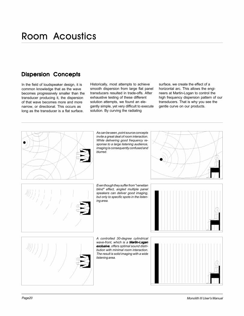
In the field of loudspeaker design, it iscommon knowledge that as the wavebecomes progressively smaller than thetransducer producing it, the dispersionof that wave becomes more and morenarrow, or directional. This occurs aslong as the transducer is a flat surface.
A controlled 30-degree cylindricalwave-front, which is a Martin-LoganMartin-LoganMartin-LoganMartin-LoganMartin-Loganexclusiveexclusiveexclusiveexclusiveexclusive, offers optimal sound distri-bution with minimal room interaction.The result is solid imaging with a widelistening area.
Even though they suffer from "venetianblind" effect, angled multiple panelspeakers can deliver good imaging,but only to specific spots in the listen-ing area.
As can be seen, point source conceptsinvite a great deal of room interaction.While delivering good frequency re-sponse to a large listening audience,imaging is consequently confused andblurred.
Historically, most attempts to achievesmooth dispersion from large flat paneltransducers resulted in trade-offs. Afterexhaustive testing of these differentsolution attempts, we found an ele-gantly simple, yet very difficult to executesolution. By curving the radiating
surface, we create the effect of ahorizontal arc. This allows the engi-neers at Martin-Logan to control thehigh frequency dispersion pattern of ourtransducers. That is why you see thegentle curve on our products.
Room Acoustics
Page21Monolith III User's Manual
General PlacementGeneral PlacementGeneral PlacementGeneral PlacementGeneral Placement
Start by making certain that both speakers are the samedistance from the walls behind or beside them and that their�toe-in� angle is the same. At this time you may want to enlistthe help of a friend or family member to assist you.
It is generally true that, as you move your speakers fartherforward into the listening environment, you will derive morespaciousness from them. Toeing them toward the middle ofthe listening area will enhance brightness.
As you place and listen, keep in mind that tight bass andclear resolution indicate proper placement and that theacoustical image is in focus. Don�t hesitate to experiment,but give each new combination of positions a thorough test.The time and effort you invest here will be well spent.
By now your speakers should be placed approximately 2 to 3feet from the back wall and at least 1 to 2 feet from the sidewalls. Your sitting distance should be further than thedistance between the speakers themselves. What you aretrying to attain is the impression of good center imaging andstage width.
There is no exact distance between speakers and listener,but there is a relationship. In long rooms, naturally, thatrelationship changes. The distance between the speakerswill be far less than the distance from you to the speakersystem. However, in a wide room you will still find that if thedistance from the listener to the speakers becomes smallerthan the distance between the speakers themselves, theimage will no longer focus in the center.
Now that you have positioned your speaker system, spendsome time listening. Wait to make any major changes inyour initial set-up for the next few days as the speakersystem itself will change subtly in its sound. Over the first 20hours of play the actual tonal quality will change slightly withdeeper bass and more spacious highs resulting.
After a few days of listening you can begin to make refine-ments and hear the differences of those refinements.
The Back WallThe Back WallThe Back WallThe Back WallThe Back Wall
Near-field reflections can also occur from your back wall. Ifyour listening position is close to a back wall, these reflec-tions can cause problems and confuse the quality ofimaging. Actually it is better for the back wall to be soft than tobe bright. If you have a hard back wall and your listeningposition is close to it, experiment with devices that will softenand absorb information, ie: wall hangings and possibly evensound absorbing panels.
The Front WallThe Front WallThe Front WallThe Front WallThe Front Wall
The wall behind your speakers should not be extremely hardor soft. For instance, a pane of glass will cause reflections,brightness, and confused imaging. Curtains, drapery, andobjects such as bookshelving can be placed along the backwall to tame an extremely hard surface. A standard sheetrock or textured wall is generally an adequate back surface ifthe rest of the room is not too bright and hard.
Sometimes walls can be too soft. If the entire front wallconsists of only heavy drapery, your system can literallysound too soft or dull. You will hear dull, muted music withlittle ambience. Harder room surfaces will actually help inthis case.
The front surface should, optimally, be one long wall withoutany doors or openings. If you have openings, the reflectionand bass characteristics from one channel to the other canbe different.
The Side WallsThe Side WallsThe Side WallsThe Side WallsThe Side Walls
The same requirements exist for side walls. Additionally, agood rule of thumb is to have the side walls as far away fromthe speaker sides as possible, minimizing near field sidewall reflections. Sometimes, if the system is bright or theimaging is not to your liking, and the sidewalls are very near,try putting curtains or softening material directly to the edgeof each speaker. An ideal side wall, however, is no side wallat all.
Placement
Page22 Monolith III User's Manual
ExperimentationExperimentationExperimentationExperimentationExperimentation
Toe-inToe-inToe-inToe-inToe-in.Now you can begin to experiment.First begin by toeing your speakersin towards the listening area andthen toeing them out. You willnotice that the tonal balancechanges ever so slightly. You willalso notice the imaging changingever so slightly. Generally it is foundthat the ideal listening position iswith the speakers slightly toed-inso that you are listening to the innerthird of the curved transducersection.
Experimenting with the toe-in willhelp in terms of tonal balance. Youwill notice that as the speakers aretoed-out, the system becomesslightly brighter than when toed-in.This design gives you the flexibilityto modify a soft or bright room.
Tilting the Speakers.Tilting the Speakers.Tilting the Speakers.Tilting the Speakers.Tilting the Speakers.(Backwards and Forwards)
As can be seen from the diagramsin the Room Acoustics section ofthis manual, the vertical dispersionis directional above and below thestat panel itself. If you sit in a tallchair, you may get better perform-ance by tilting the speakers backso that the high frequencies are onaxis with your ears. Otherwise, witha normal sofa and normal listen-ing, tilt the speakers only slightlyback if not straight up. Make sure,when listening, that the verticalalignment, distance from the backwall, and toe in is exactly the samefrom one speaker to the other. Thiswill greatly enhance the quality ofyour imaging.
A Final WordA Final WordA Final WordA Final WordA Final Word
Final Placement.Final Placement.Final Placement.Final Placement.Final Placement.After obtaining good wall treat-ments and attaining proper angle,begin to experiment with thedistance from the back wall. Moveyour speaker slightly forward intothe room. What happened to thebass response? What happened tothe imaging? If the imaging is moreopen and spacious and the bassresponse tightened, that is asuperior position. Move thespeakers back six inches from theinitial set-up position. Again, listento the imaging and bass response.There will be a position where youwill have pin-point imaging andgood bass response. That positionbecomes the point of the optimalplacement from the back wall.
Now experiment with placing thespeakers farther apart. As thespeakers are positioned fartherapart, listen again, not so much forbass response but for stage widthand good pin-point focusing.
Your ideal listening position andspeaker position will be deter-mined by the following:
1. Tightness and extension of bass response.2. The width of the stage.3. The pin-point focusing of imaging.
Once you have found the best of allthree of those considerations, youwill have your best speakerlocation.
Placement
Imaging.Imaging.Imaging.Imaging.Imaging.In their final location, your Monolithsshould have a stage width some-what wider than the speakersthemselves. On well recordedmusic, the instruments shouldextend beyond the edges of eachspeaker to the left and to the right,yet a vocalist should appear directlyin the middle. The size of theinstruments should be neither toolarge nor too small. Additionally,you should find good clues as tostage depth.
Bass Response.Bass Response.Bass Response.Bass Response.Bass Response.Your bass response should neitherbe one note nor should it be tooheavy. It should extend fairly deepto all but the deepest organpassages yet it should be tight andwell defined. Kick-drums should betight and percussive, string bassnotes should be uniform andconsistent throughout the entirety ofthe run without any booming orthudding.
Tonal Balance.Tonal Balance.Tonal Balance.Tonal Balance.Tonal Balance.Voices should be natural and full,cymbals should be detailed andarticulate yet not bright andpiercing, pianos should have a nicetransient characteristic and deeptonal registers as well. If youcannot attain these virtues, re-readthe section on Room Acoustics.This will give you clues on how toget closer to those ideal virtues.
Page23Monolith III User's Manual
Associated EquipmentAssociated EquipmentAssociated EquipmentAssociated EquipmentAssociated Equipment
Your Martin-Logan Dealer wascarefully selected by our companybecause they are knowledgeable,experienced and dedicated to musicalexcellence and customer satisfaction.
They have the ability to help youacquire the very best in audio equip-ment. They are likely to choose thatequipment from among a small groupof manufacturers that are committed tothe faithful recreation of music.
Your new MONOLITH III speakers arequite honest in revealing the relativestrengths and weaknesses of theequipment used with them. While theMonolith will bring to life the sonicdelights of state-of-the-art compo-nents, it will with equal clarity bring outany system flaws. This does not meanthat expensive equipment is aprerequisite to good sound from theMonolith, but rather that the equipmentmust be wisely selected and setupwith care. The rewards will be wellworth the effort.
As time goes by, you may find itinstructive to discuss with your dealerthe merits and advantages of carefullyupgrading certain pieces of yourassociated equipment.
CareCareCareCareCare
The Martin-Logan Monolith has beencarefully designed and preciselyengineered. With a little care you canrest assured that they will continue tolook as good as they sound for yearsto come.
Do not spray any cleaning solutions onthe electrostatic element, as this couldimpair the speakers performance.Dust may be removed with a brushattachment on a vacuum cleaner oryou may blow it off with compressedair. Silicone dusting sprays, abrasiveor solvent-based cleaners should notnotnotnotnotbe used on any portions of thespeaker.
Solid FootingSolid FootingSolid FootingSolid FootingSolid Footing
It is best to have a the Monolithscoupled firmly with the floor. After livingand experimenting with the placementof your Monoliths, you should use thespikes included in your owners kit.Bass response will tighten andimaging will become more coherent,fixed and detailed. It is best not toimplement the spikes however, untilyou have decided upon the finalplacement of the speaker, as they candamage the floor if the speaker ismoved.
Enjoy YourselfEnjoy YourselfEnjoy YourselfEnjoy YourselfEnjoy Yourself
The MONOLITH III is a very refinedspeaker and, as such, benefits fromcareful set-up. With the information inthis manual in mind, you will find, overyour months of listening, that smallchanges can result in demonstrabledifferences. As you live with yourspeakers, do not be afraid to experi-ment with their positioning until youfind the optimal relationship betweenyour room and your speaker system.Your efforts will be rewarded.
You are now armed with the basics ofroom acoustics and the specificfundamentals of the MONOLITH IIIloudspeaker system. Enjoy yourselfand happy listening.
General Information
Page24 Monolith III User's Manual
How is it that music can be recreated bysomething that you are able to seethrough? Electrostatic energy makesthis possible.
Where the world of traditional loud-speaker technology deals with cones,domes, diaphrams, and ribbons thatare moved with magnetism, the worldof electrostatic loudspeakers deals withcharged electrons attracting and
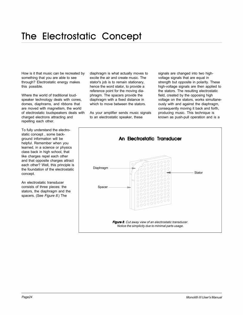
diaphragm is what actually moves toexcite the air and create music. Thestator's job is to remain stationary,hence the word stator, to provide areference point for the moving dia-phragm. The spacers provide thediaphragm with a fixed distance inwhich to move between the stators.
As your amplifier sends music signalsto an electrostatic speaker, these
signals are changed into two high-voltage signals that are equal instrength but opposite in polarity. Thesehigh-voltage signals are then applied tothe stators. The resulting electrostaticfield, created by the opposing highvoltage on the stators, works simultane-ously with and against the diaphragm,consequently moving it back and forth,producing music. This technique isknown as push-pull operation and is a
The Electrostatic Concept
repelling each other.
To fully understand the electro-static concept , some back-ground information will behelpful. Remember when youlearned, in a science or physicsclass back in high school, thatlike charges repel each otherand that opposite charges attracteach other? Well, this principle isthe foundation of the electrostaticconcept.
An electrostatic transducerconsists of three pieces: thestators, the diaphragm and thespacers. (See Figure 8.) The
Stator
An Electrostatic TransducerAn Electrostatic TransducerAn Electrostatic TransducerAn Electrostatic TransducerAn Electrostatic Transducer
Figure 8Figure 8Figure 8Figure 8Figure 8. Cut away view of an electrostatic transducer.Notice the simplicity due to minimal parts usage.
Diaphragm
Spacer
Page25Monolith III User's Manual
major contributor to the sonic purity ofthe electrostatic concept due to itsexceptional linearity and low distortion.
Since the diaphragm of an electrostaticspeaker is uniformly driven over itsentire area, it can be extremely light andflexible. This allows it to be veryresponsive to transients, thus perfectlytracing the music signal. As a result ,great delicacy, nuance and clarity is
possible. When you look at the prob-lems of traditional electromagneticdrivers, you can easily see why this isso beneficial .
The cones and domes which are usedin traditional electromagnetic driverscannot be driven uniformly because oftheir design. Cones are driven only atthe apex. Domes are driven at theirperimeter. As a result, the rest of the
cone or dome is just "along for the ride".The basic concept of these driversrequire that the cone or dome beperfectly rigid, damped and close tomassless. Unfortunately these condi-tions are not available in our worldtoday.
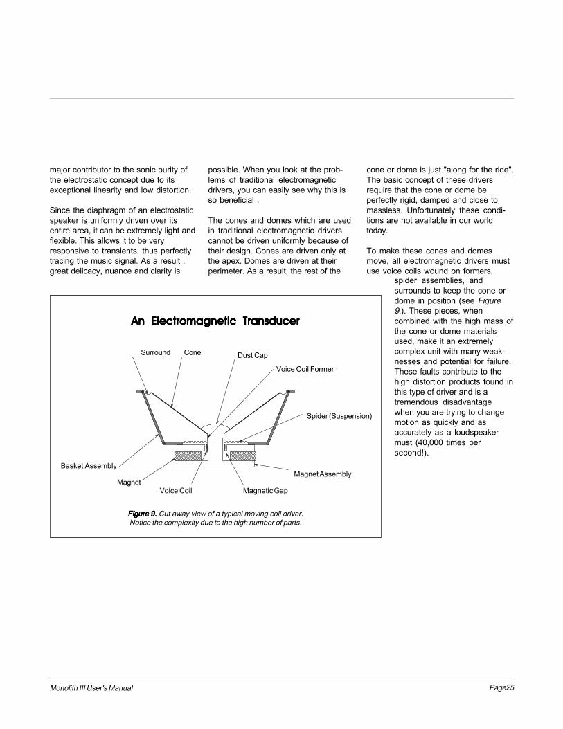
To make these cones and domesmove, all electromagnetic drivers mustuse voice coils wound on formers,
spider assemblies, andsurrounds to keep the cone ordome in position (see Figure9.). These pieces, whencombined with the high mass ofthe cone or dome materialsused, make it an extremelycomplex unit with many weak-nesses and potential for failure.These faults contribute to thehigh distortion products found inthis type of driver and is atremendous disadvantagewhen you are trying to changemotion as quickly and asaccurately as a loudspeakermust (40,000 times persecond!).
Figure 9.Figure 9.Figure 9.Figure 9.Figure 9. Cut away view of a typical moving coil driver.Notice the complexity due to the high number of parts.
Voice Coil Magnetic Gap
Magnet Assembly
Spider (Suspension)
Voice Coil Former
Dust CapConeSurround
Magnet
Basket Assembly
An Electromagnetic TransducerAn Electromagnetic TransducerAn Electromagnetic TransducerAn Electromagnetic TransducerAn Electromagnetic Transducer
Page26 Monolith III User's Manual
1. Full Range Operation1. Full Range Operation1. Full Range Operation1. Full Range Operation1. Full Range Operation
The most significant advantage ofMartin-Logan's exclusive transducertechnology reveals itself when you lookat examples of other loudspeakerproducts on the market today.
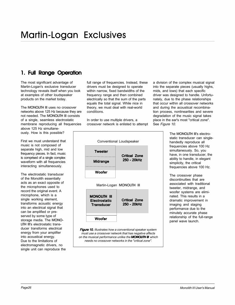
The MONOLITH III uses no crossovernetworks above 125 Hz because they arenot needed. The MONOLITH III consistsof a single, seamless electrostaticmembrane reproducing all frequencies
full range of frequencies. Instead, thesedrivers must be designed to operatewithin narrow, fixed bandwidths of thefrequency range and then combinedelectrically so that the sum of the partsequals the total signal. While nice intheory, we must deal with real-worldconditions.
In order to use multiple drivers, acrossover network is enlisted to attempt
a division of the complex musical signalinto the separate pieces (usually highs,mids, and lows) that each specificdriver was designed to handle. Unfortu-nately, due to the phase relationshipsthat occur within all crossover networksand during the acoustical recombina-tion process, nonlinearities and severedegradation of the music signal takesplace in the ear's most "critical zone".See Figure 10.
The MONOLITH III's electro-static transducer can single-handedly reproduce allfrequencies above 100 Hzsimultaneously. So, youhave, in one transducer, theability to handle, in elegantsimplicity, the criticalfrequencies above 100 Hz.
The crossover phasediscontinuities that areassociated with traditionaltweeter, midrange, andwoofer systems are elimi-nated. This results in adramatic improvement inimaging and stagingperformance due to theminutely accurate phaserelationship of the full-rangepanel wave launch.
Critical ZoneCritical ZoneCritical ZoneCritical ZoneCritical Zone250 - 20kHz250 - 20kHz250 - 20kHz250 - 20kHz250 - 20kHz
TweeterTweeterTweeterTweeterTweeter
MidrangeMidrangeMidrangeMidrangeMidrange
WooferWooferWooferWooferWoofer
Critical ZoneCritical ZoneCritical ZoneCritical ZoneCritical Zone250 - 20kHz250 - 20kHz250 - 20kHz250 - 20kHz250 - 20kHz
MONOLITH IIIMONOLITH IIIMONOLITH IIIMONOLITH IIIMONOLITH IIIElectrostaticElectrostaticElectrostaticElectrostaticElectrostaticTransducerTransducerTransducerTransducerTransducer
Martin-Logan MONOLITH III
Conventional Loudspeaker
Figure 10. Figure 10. Figure 10. Figure 10. Figure 10. Illustrates how a conventional speaker systemmust use a crossover network that has negative affects
on the musical performance unlike the MONOLITH III MONOLITH III MONOLITH III MONOLITH III MONOLITH III whichneeds no crossover networks in the "critical zone".
WooferWooferWooferWooferWoofer
Martin-Logan Exclusives
above 125 Hz simultane-ously. How is this possible?
First we must understand thatmusic is not composed ofseparate high, mid and lowfrequency pieces. In fact, musicis comprised of a single complexwaveform with all frequenciesinteracting simultaneously.
The electrostatic transducerof the Monolith essentiallyacts as an exact opposite ofthe microphones used torecord the original event. Amicrophone, which is asingle working element,transforms acoustic energyinto an electrical signal thatcan be amplified or pre-served by some type ofstorage media. The MONO-LITH III's electrostatic trans-ducer transforms electricalenergy from your amplifierinto acoustical energy.Due to the limitations ofelectromagnetic drivers, nosingle unit can reproduce the
Page27Monolith III User's Manual
2. Curvilinear Line2. Curvilinear Line2. Curvilinear Line2. Curvilinear Line2. Curvilinear Line Source Source Source Source Source
Since the beginning of Audio, achievingsmooth dispersion has long been aproblem for all loudspeaker designers.Large panel transducers present evenmore of a challenge because the largerthe panel, the more directional thedispersion pattern becomes.
Full range electrostats have long beenone of the most problematic transduc-ers because they attain their full rangecapabilities via a large surface area. Itlooked as if they were in direct conflict tosmooth dispersion and almost everyattempt to correct this resulted in eitherpoor dispersion or a serious compro-mise in sound quality.
After extensive research, Martin-Loganengineers discovered an elegantlysimple solution to achieve a smoothpattern of dispersion without degradingsound quality. By curving the horizontalplane of the electrostatic transducer, acontrolled horizontal dispersion patterncould be achieved, yet the purity of thealmost massless electrostatic dia-phragm remained uncompromised.After creating this technology, wedeveloped the production capability tobring this technology out of the labora-tory and into the market place.
You will find this proprietary Martin-Logan technology used in all of ourproducts. It is one of the many reasonsbehind our reputation for high qualitysound with practical usability. This isalso why you see the unique "seethrough" cylindrical shape of all Martin-Logan products.
3. Hybrid Technology3. Hybrid Technology3. Hybrid Technology3. Hybrid Technology3. Hybrid Technology
When Martin-Logan introduced theMonolith back in 1982, it was the firstcompany to commercially recognize theperformance potential available bymating the air-moving capabilities of adynamic woofer with the inherent speedand accuracy of an electrostatic panel.
Since then, refinements in the actualdriver assemblies, crossover compo-nents, and materials used in theconstruction of our hybrid speakers havebrought this concept to its full potential.
4. Vapor Deposited4. Vapor Deposited4. Vapor Deposited4. Vapor Deposited4. Vapor DepositedFilmFilmFilmFilmFilm
The diaphragm material used in allMartin-Logan speakers employs anextremely sophisticated conductivesurface that has been vapor depositedon the polymer surface at an atomiclevel. Copper oxide and palladium havebeen vaporized and electrostaticallydriven into the surface of the polymerfilm in a vacuum chamber. This processallows an optically transparent surfaceadding no mass to the diaphragm thatis extremely uniform in its surfaceresistivity characteristics. This uniformsurface resistivity controls the electro-static charge on the diaphragm surfaceand regulates its migration. As a result,no discharging or �arcing� can occur.
5. Transducer Integrity5. Transducer Integrity5. Transducer Integrity5. Transducer Integrity5. Transducer Integrity
All Martin-Logan transducers begin withtwo pieces of high grade, cold rolledsteel. The rear stator is manufacturedfrom 16 gauge material while the frontstator from 18 gauge. These steelpieces are then custom perforated andinsulated with an exotic nylon compos-ite coating. This proprietary coatinginsulates the stator to 3 times its actualneeded working voltage and gives theMonolith a wide margin of safe opera-tion. In addition to the electrical insula-tion properties, this coating alsoprovides the Monolith with a durable,attractive finish that dampens the steelto prevent ringing. These pieces arethen sandwiched with our exclusivevapor deposited diaphragm andspacers into a curved geometry andbonded together with aerospaceadhesives whose strength exceeds thatof welding.
When all of these various techniquesare combined, we get a transducer thatis attractive, durable, highly rigid, welldampened, and neutral.

Page28 Monolith III User's Manual
Questions
Could my children, pets, or myselfCould my children, pets, or myselfCould my children, pets, or myselfCould my children, pets, or myselfCould my children, pets, or myselfbe shocked by the high-voltagebe shocked by the high-voltagebe shocked by the high-voltagebe shocked by the high-voltagebe shocked by the high-voltagepresent in the electrostatic panel?present in the electrostatic panel?present in the electrostatic panel?present in the electrostatic panel?present in the electrostatic panel?
No. High voltage with low current isnot dangerous. As a matter of fact, thehigh-voltage present in our speakersis10 times less than the staticelectricity that you generate when youtake off a sweater. (About 30,000volts!)
What size of an amplifier should IWhat size of an amplifier should IWhat size of an amplifier should IWhat size of an amplifier should IWhat size of an amplifier should Iuse with the Monoliths?use with the Monoliths?use with the Monoliths?use with the Monoliths?use with the Monoliths?
We recommend an amplifier with 100to 200 watts per channel for mostapplications.
Do I need an amplifier with highDo I need an amplifier with highDo I need an amplifier with highDo I need an amplifier with highDo I need an amplifier with highcurrent capability?current capability?current capability?current capability?current capability?
No. The Monolith's impedancecharacteristics do not require that ahigh current amplifier be used.However, it is important that theamplifier be stable operating intovarying impedance loads.
Should I unplug my Monoliths duringShould I unplug my Monoliths duringShould I unplug my Monoliths duringShould I unplug my Monoliths duringShould I unplug my Monoliths duringa thunderstorm?a thunderstorm?a thunderstorm?a thunderstorm?a thunderstorm?
Yes. Or before. It�s a good idea todisconnect all of your audio/videocomponents during stormy weather.
Will my electric bill go �sky high� byWill my electric bill go �sky high� byWill my electric bill go �sky high� byWill my electric bill go �sky high� byWill my electric bill go �sky high� byleaving my speakers plugged in allleaving my speakers plugged in allleaving my speakers plugged in allleaving my speakers plugged in allleaving my speakers plugged in allthe time?the time?the time?the time?the time?
No. A pair of Monoliths draw about 5watts maximum.
Is there likely to be any interactionIs there likely to be any interactionIs there likely to be any interactionIs there likely to be any interactionIs there likely to be any interactionbetween the Monoliths and thebetween the Monoliths and thebetween the Monoliths and thebetween the Monoliths and thebetween the Monoliths and thetelevision in my Audio/Videotelevision in my Audio/Videotelevision in my Audio/Videotelevision in my Audio/Videotelevision in my Audio/Videosystem?system?system?system?system?
Actually, there is less interactionbetween a television and an electro-static speaker than between atelevision and a conventional system.The magnets in conventional speak-ers do interact with televisions tubes.However, we do recommend that youkeep your speakers at least one footaway from the television because ofthe dynamic woofer they employ.
Will excessive smoke or dust causeWill excessive smoke or dust causeWill excessive smoke or dust causeWill excessive smoke or dust causeWill excessive smoke or dust causeany problems?any problems?any problems?any problems?any problems?
Exposure to excessive smoke or dustmay potentially affect the performanceof the electrostatic membrane. Whennot in use, you should unplug thespeaker and cover with the plasticbags that the speakers were originallypacked in.
If my child punctured the diaphragmIf my child punctured the diaphragmIf my child punctured the diaphragmIf my child punctured the diaphragmIf my child punctured the diaphragmwith a pencil, stick, or similar item.,with a pencil, stick, or similar item.,with a pencil, stick, or similar item.,with a pencil, stick, or similar item.,with a pencil, stick, or similar item.,how extensive would the damage tohow extensive would the damage tohow extensive would the damage tohow extensive would the damage tohow extensive would the damage tothe speaker be?the speaker be?the speaker be?the speaker be?the speaker be?
You should probably replace theelectrostatic element. However, thisdepends upon the extent of thedamage.
Will exposure to sunlight affect theWill exposure to sunlight affect theWill exposure to sunlight affect theWill exposure to sunlight affect theWill exposure to sunlight affect thelife or performance of the Monolith?life or performance of the Monolith?life or performance of the Monolith?life or performance of the Monolith?life or performance of the Monolith?
We recommend that you not placeyour Monoliths in direct sunlight asthe ultraviolet (UV) rays from the suncan cause deterioration of theelectrostatic membrane. However,small exposures to UV should notcause a problem.

Page29Monolith III User's Manual
Lack of BassLack of BassLack of BassLack of BassLack of Bass
Check your speaker wires. Is the polarity correct?
Poor ImagingPoor ImagingPoor ImagingPoor ImagingPoor Imaging
Check placement. Are both speakers the same dis-tance from the walls? Do they have the same amountof toe-in? Try moving the speakers away from the backand side walls.
Check the polarity of the speaker wires. Are theyconnected properly?
Popping and Ticking Sounds, Funny NoisesPopping and Ticking Sounds, Funny NoisesPopping and Ticking Sounds, Funny NoisesPopping and Ticking Sounds, Funny NoisesPopping and Ticking Sounds, Funny Noises
These occasional noises are harmless and will nut hurtyour audio system or your speakers. All electrostaticspeakers are guilty of making odd noises at one time oranother.
These noises may be caused by dirt and dust particlescollecting on the speaker, by high humidity or by AC linefluctuations that may occur in your area.
Dirt and dust may be vacuumed off with a brushattachment connected to your vacuum cleaner or youmay blow them off with compressed air.
DO NOT SPRAY ANY KIND OF CLEANING AGENTON OR IN CLOSE PROXIMITY TO THEM.
No Output.No Output.No Output.No Output.No Output.
Check that all your system components are turned on.
Check your speaker wires and connections.
Check all interconnecting cables.
Weak Output, Loss of Highs.Weak Output, Loss of Highs.Weak Output, Loss of Highs.Weak Output, Loss of Highs.Weak Output, Loss of Highs.
Check the power cord. Is it properly connected to thespeaker?
If you are bi-amplifiying, check your high frequencyamplifier. Is it functioning properly?
Exaggerated Highs, Brightness.Exaggerated Highs, Brightness.Exaggerated Highs, Brightness.Exaggerated Highs, Brightness.Exaggerated Highs, Brightness.
Check the toe-in of the speakers. Read Room Place-ment for more information.
Muddy BassMuddy BassMuddy BassMuddy BassMuddy Bass
Check placement. Try moving the speakers closer tothe back and side walls.
Check the type of feet being used. Try attaching thecoupling spikes.
If you are using the IIIx CROSSOVER, adjust the basscontour controls until you get the desired response
Troubleshooting
Page30 Monolith III User's Manual
ACACACACAC. Abbreviation for alternatingcurrent.
Active crossoverActive crossoverActive crossoverActive crossoverActive crossover. Uses activedevices (transistors, IC�s,tubes) and some form of powersupply to operate.
AmplitudeAmplitudeAmplitudeAmplitudeAmplitude. The extreme range of asignal. Usually measured fromthe average to the extreme.
ArcArcArcArcArc. The visible sparks generated byan electrical discharge.
BandwidthBandwidthBandwidthBandwidthBandwidth. The range of frequencieswithin a radiation band requiredto transmit a particular signal.
BassBassBassBassBass. The lowest frequencies ofsound.
Bi-AmplificationBi-AmplificationBi-AmplificationBi-AmplificationBi-Amplification. Uses an electroniccrossover or line-level passivecrossover and separate poweramplifiers for the high and lowfrequency loudspeaker drivers.
CapacitanceCapacitanceCapacitanceCapacitanceCapacitance. That property of acapacitor which determines howmuch charge can be stored in itfor a given potential differencebetween its terminals, measuredin farads, by the ratio of thecharge stored to the potentialdifference.
CapacitorCapacitorCapacitorCapacitorCapacitor. A device consisting of twoor more conducting platesseparated from one another byan insulating material and usedfor storing an electrical charge.Sometimes called a condenser.
Glossary
ClippingClippingClippingClippingClipping. Distortion of a signal by itsbeing chopped off. An overloadproblem caused by pushing anamplifier beyond its capabilities.The flat-topped signal has highlevels of harmonic distortionwhich creates heat in a loud-speaker and is the major causeof loudspeaker componentfailure.
CrossoverCrossoverCrossoverCrossoverCrossover. An electrical circuit thatdivides a full bandwidth signalinto the desired frequency bandsfor the loudspeaker components.
dB (decibel)dB (decibel)dB (decibel)dB (decibel)dB (decibel). A numerical expressionof the relative loudness of asound. The difference in decibelsbetween two sounds is ten timesthe common logarithm of the ratioof their power levels.
DCDCDCDCDC. Abbreviation for direct current.
DiffractionDiffractionDiffractionDiffractionDiffraction. The breaking up of asound wave caused by sometype of mechanical interferencesuch as a cabinet edge, grillframe, or other similar object.
DiaphragmDiaphragmDiaphragmDiaphragmDiaphragm. A thin flexible membraneor cone that vibrates in responseto electrical signals to producesound waves.
DistortionDistortionDistortionDistortionDistortion. Usually referred to interms of total harmonic distortion(THD) which is the percentage ofunwanted harmonics of the drivesignal present with the wantedsignal. Generally used to meanany unwanted change introducedby the device under question.
DriverDriverDriverDriverDriver. See transducer.
Dynamic RangeDynamic RangeDynamic RangeDynamic RangeDynamic Range. The range betweenthe quietest and the loudestsounds a device can handle(often quoted in dB).
EfficiencyEfficiencyEfficiencyEfficiencyEfficiency. The acoustic powerdelivered for a given electricalinput. Often expressed asdecibels/watt/meter (dB/w/m).
ESLESLESLESLESL. Abbreviation for electrostaticloudspeaker.
HeadroomHeadroomHeadroomHeadroomHeadroom. The difference, in deci-bels, between the peak and RMSlevels in program material.
HybridHybridHybridHybridHybrid. A product created by themarriage of two different tech-nologies. Meant here as thecombination of a dynamic wooferwith an electrostatic transducer.
Hz (Hertz)Hz (Hertz)Hz (Hertz)Hz (Hertz)Hz (Hertz). Unit of frequency equiva-lent to the number of cycles persecond.
ImagingImagingImagingImagingImaging. To make a representation orimitation of the original sonicevent.
ImpedanceImpedanceImpedanceImpedanceImpedance. The total oppositionoffered by an electric circuit to theflow of an alternating current of asingle frequency. It is a combina-tion of resistance and reactanceand is measured in ohms.Remember that a speaker�simpedance changes withfrequency, it is not a constant

Page31Monolith III User's Manual
value.
InductanceInductanceInductanceInductanceInductance. The property of anelectric circuit by which a varyingcurrent in it produces a varyingmagnetic field that introducesvoltages in the same circuit or ina nearby circuit. It is measured inhenrys.
InductorInductorInductorInductorInductor. A device designed primarilyto introduce inductance into anelectric circuit. Sometimes calleda choke or coil.
LinearityLinearityLinearityLinearityLinearity. The extent to which anysignal handling process isaccomplished without amplitudedistortion.
MidrangeMidrangeMidrangeMidrangeMidrange. The middle frequencieswhere the ear is the mostsensitive.
Passive crossoverPassive crossoverPassive crossoverPassive crossoverPassive crossover. Uses no activecomponents (transistors, IC�s,tubes) and needs no powersupply (AC, DC, battery) tooperate. The crossover in atypical loudspeaker is of thepassive variety. Passive cross-overs consist of capacitors,inductors and resistors.
PhasePhasePhasePhasePhase. The amount by which onesine wave leads or lags a secondwave of the same frequency. Thedifference is described by theterm phase angle. Sine waves in
phase reinforce each other; thoseout of phase cancel.
Pink noisePink noisePink noisePink noisePink noise. A random noise used inmeasurements, as it has thesame amount of energy in eachoctave.
PolarityPolarityPolarityPolarityPolarity. The condition of beingpositive or negative with respectto some reference point or object.
RMSRMSRMSRMSRMS. Abbreviation for root meansquare. The effective value of agiven waveform is its RMS value.Acoustic power is proportional tothe square of the RMS soundpressure.
ResistanceResistanceResistanceResistanceResistance. That property of aconductor by which it opposesthe flow of electric current,resulting in the generation of heatin the conducting material,usually expressed in ohms.
ResistorResistorResistorResistorResistor. A device used in a circuitprimarily to provide resistance.
ResonanceResonanceResonanceResonanceResonance. The effect producedwhen the natural vibrationfrequency of a body is greatlyamplified by reinforcing vibrationsat the same or nearly the samefrequency from another body.
SensitivitySensitivitySensitivitySensitivitySensitivity. Volume of sound deliv-ered for a given electrical input.
StatorStatorStatorStatorStator. The fixed part forming the
reference for the moving dia-phragm in a planar speaker.
THDTHDTHDTHDTHD. Abbreviation for total harmonicdistortion. (See Distortion.)
TIMTIMTIMTIMTIM. Abbreviation for transientintermodulation distortion. (SeeDistortion.)
TransducerTransducerTransducerTransducerTransducer. Any of various devicesthat transmit energy from onesystem to another, sometimesone that converts the energy inform. Loudspeaker transducersconvert electrical energy intomechanical motion.
TransientTransientTransientTransientTransient. Applies to that which lastsor stays but a short time. Achange from one steady-statecondition to another.
TransmitTransmitTransmitTransmitTransmit. To cause sound to passthrough air or some othermedium.
TweeterTweeterTweeterTweeterTweeter. A small drive unit designedto produce only high frequencies.
WavelengthWavelengthWavelengthWavelengthWavelength. The distance measuredin the direction of progression ofa wave, from any given pointcharacterized by the same phase.
White noiseWhite noiseWhite noiseWhite noiseWhite noise. A random noise used inmeasurements, as it has thesame amount of energy at eachfrequency.
WooferWooferWooferWooferWoofer. A drive unit operating in thebass frequencies only. Driveunits in two-way systems are nottrue woofers but are moreaccurately described as beingmid/bass drivers.

$ 3.00
2001 delaware street, p.o. box 741, lawrence, kansas 66044, phone: 913.749.0133, fax: 913.749.5320
© 1989 Martin-Logan Ltd. All rights reserved.