module design - homepage • greenlionproject.eu · 2 module design developing a modular battery...
TRANSCRIPT

ADVANCED MANUFACTURING PROCESSES
FOR LOW COST GREENER LI-ION BATTERIES
MODULE DESIGN Developing a modular battery

1
Index
1 Introduction .................................................................................................................. 2
2 Work performed ............................................................................................................ 3
3 Results and discussion .................................................................................................. 4
3.1 Stage 1: preliminary electrical specifications and rough module geometry ......... 4
3.1.1 Module thermo - mechanical design ............................................................................................. 4
3.2 Stage 2: module and cell terminals definition ...................................................... 8
3.2.1 Module thermo - mechanical design ............................................................................................. 8
3.3 Stage 3: module geometry definition .................................................................. 10
3.3.1 Module thermo - mechanical design ........................................................................................... 10
3.3.2 Module SOC and SOH definition .................................................................................................. 11
3.4 Stage 4: module details and BMS definition ........................................................ 11
3.4.1 Module thermo - mechanical design ............................................................................................ 11
3.4.2 Module SOC and SOH definition ................................................................................................. 13
4 Conclusions .................................................................................................................. 17
5 Annex ........................................................................................................................... 18
6 Contacts & References ................................................................................................ 20

2
MODULE DESIGN
Developing a modular battery …
… allows an easier handling of cells within a complete battery pack. At this battery module level,
GREENLION project designed an autonomous unit, including its own electrical and thermal
management. It was planned as a simple and reliable building block that would allow the manufacturing
and maintenance of the whole battery pack easier and more inexpensively, with the lowest possible
environmental impact.
1 Introduction
The objective of this chapter is to summarize the work done in the design of the Li-ion battery module,
based both on the characteristics of the cells developed within the project and the requirements of the EV,
in order to have an optimized solution.
In order to achieve a modular design as safe and reliable as possible, the module includes a CMC (Cell
Module Controller), which includes cells temperature monitoring. The CMC monitors each cell voltage
and balance them so that their SOC (state of charge) is as equal as possible, as well as their ‘state of health’
(SOH, capacity of the cells at a given time compared to that when they were new). During the cell design
development, it was analyzed whether current SOC estimation algorithms (SOC-OCV-look up table,
kalman filter …) were still applicable and which method fitted best. A new SOC algorithm was customized
in order to reach the needed level of accuracy for the developed cells. Moreover, a SOH algorithm was
defined.
Due to production diversification on the one hand and different aging on the other, cell capacities
decrease unequally as well as the internal resistance increase unequally. Therefore, cell equalization was
considered. The equalization effort was analyzed and suitable balancing strategies compared (active,
passive). A reasonable equalization topology and strategy were then selected.
The cooling system and the module housing were designed in order to have a light system that can be
easily disassembled. For such task, the air cooling was studied as an alternative to the liquid cooling
system with single piece of injection-molded aluminum housing. Thermal simulation was executed for
identifying the suited thermal configuration.
Also, the GREELION battery modules were designed to favor an extensive recycling of the material
components upon the end of life by easier disassembling and the use of environmental friendly
components.
3
2 Work performed
Initially the main part of the work was focused on the module design without knowing specifically the cell
shape, since it was going to be developed along the project. Therefore the module design team supported
the cell shape and configuration selection task. Regarding the module design, at the early stages of this
work, just rough ideas about easy to assemble and disassemble designs were discussed and existing
commercial materials sought. As well as the connection with the cell designers, it was fundamental to link
the module design activity with the partners in charge of the module industrialization in order to define a
module design, which could be assembled both manually and in an industrial environment.
In stage 2, once the cell specifications were more clearly defined as well as the module dimensions, a
specific CAD module design started with initial sketches. The detail level increased as soon as the rest of
parameters were defined mainly by the module end user and cell manufacturer.
Stage 3 and stage 4 followed the path of stage 2 by adjusting the developed work to some modifications on
the cell and module design and adding at theses stages the SOC and SOH estimation task. These
estimators were finally implemented in the PCB (balancer board). Thermal simulations were conducted in
these 2 last stages once the boundary conditions were fixed.
4
3 Results and discussion
3.1 Stage 1: preliminary electrical specifications and rough module
geometry In this first stage the cell shape was totally undefined, although the module volume was defined. A
discussion on the best cell shape and positioning was held and preliminary ideas about the module layout
were launched.
3.1.1 Module thermo - mechanical design
The first steps of the module design were focused on the mechanical design and module assembly. While
the active elements of the cell and its shape were defined, the module designers were looking for different
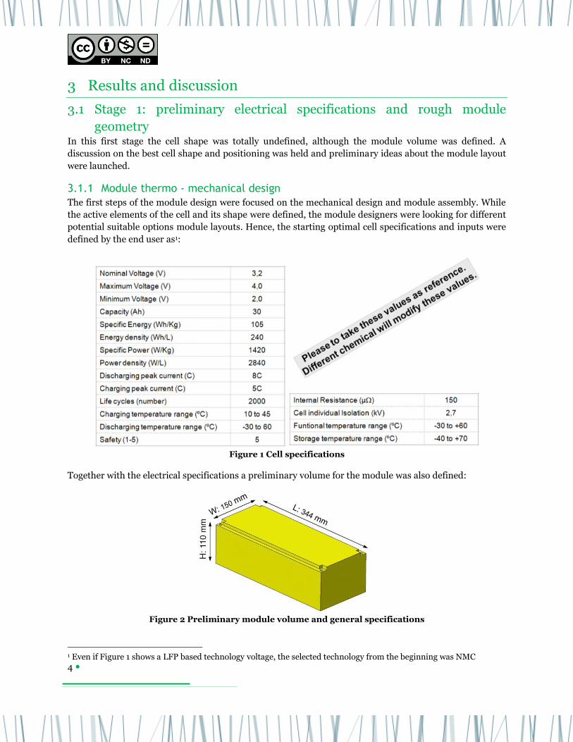
potential suitable options module layouts. Hence, the starting optimal cell specifications and inputs were
defined by the end user as1:
Figure 1 Cell specifications
Together with the electrical specifications a preliminary volume for the module was also defined:
Figure 2 Preliminary module volume and general specifications
1 Even if Figure 1 shows a LFP based technology voltage, the selected technology from the beginning was NMC
• Preliminary basic specification for the battery module
– 12 cells 38.4 V, 1.152 kWh
– Energy density [Wh/l] = 202.96
– Maximum current [A] = 240
SEAT

5
Therefore the preliminary basic specifications for the battery module were:
12 cells (12s1p) 38.4 V, 1.152 kWh
Energy density [Wh/l] ≈ 200
Maximum current [A] = 240
Tabs on one side of the module and included in one of the faces of the cell (actually tabs
characteristics were free and defined by the cell and module designers)
Since there is a strong correlation between cell and module dimensions and performance of the design,
cell and module designers jointly evaluated pros and cons of the different cell configurations keeping the
module dimensions previously defined. Next table shows a summary of the developed analysis by
highlighting in red the weak points in each case (X & Y & thickness are related to cell shape):
Table 1 Cell geometrical proposals and disadvantages for each case
As none of the configurations resulted in an optimal design for the defined volume, new module
dimensions were proposed for an optimum cell size ratio.
Figure 3 Proposed cell and general specifications
6
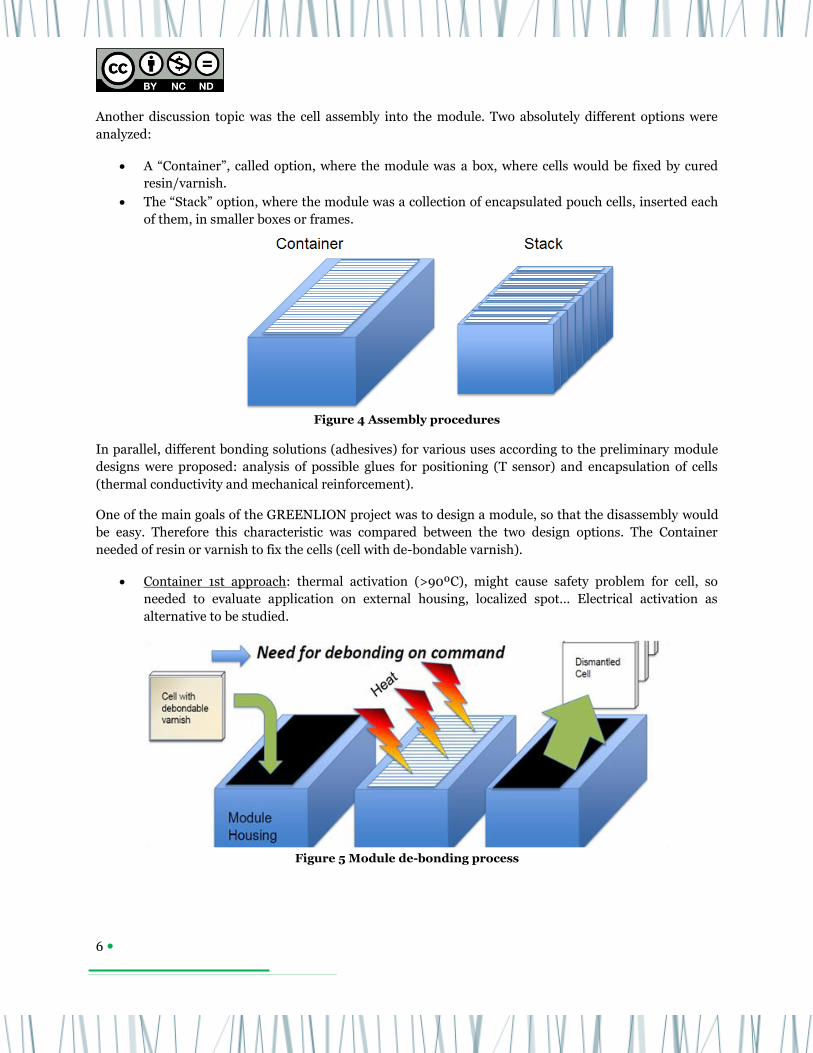
Another discussion topic was the cell assembly into the module. Two absolutely different options were
analyzed:
A “Container”, called option, where the module was a box, where cells would be fixed by cured
resin/varnish.
The “Stack” option, where the module was a collection of encapsulated pouch cells, inserted each
of them, in smaller boxes or frames.
Figure 4 Assembly procedures
In parallel, different bonding solutions (adhesives) for various uses according to the preliminary module
designs were proposed: analysis of possible glues for positioning (T sensor) and encapsulation of cells
(thermal conductivity and mechanical reinforcement).
One of the main goals of the GREENLION project was to design a module, so that the disassembly would
be easy. Therefore this characteristic was compared between the two design options. The Container
needed of resin or varnish to fix the cells (cell with de-bondable varnish).
Container 1st approach: thermal activation (>90ºC), might cause safety problem for cell, so
needed to evaluate application on external housing, localized spot… Electrical activation as
alternative to be studied.
Figure 5 Module de-bonding process

7
Different potting products were studied:
Table 2 Potting possibilities
In the case of the Stack initial option, cells were also encapsulated also using resin/varnish, but
the cell manufacturer in the project, preferred a 2 part-frame system (no adhesion to the cell, only
mechanical fastening).
The cell encapsulation could have more functions than just fixing and keeping the cell within. It
could be used for crossing along studs and/or a mechanical male-female assembly between
consecutive stacked framed cells, fixed by an elastic embracing band. This multi-functionality was
observed in the next module design stages.
Another advantage of this assembly was the possibility of integrating a venting valve inside the
individual cell capsule. The objective was to allow degassing and preventing run away along with
reversible sealing capability (if possible). Once again, this idea would remain till the end of the
module development.
Regarding both assemblies (Container and Stack) another concern arose about the cell swelling restriction
since the cell would be trapped into a stiff resin box (big or individual). Besides, trapped air chambers
should be minimized in order to improve the heat evacuation from the cells, so thermal conductive pastes
or soft pads could be suitable. An interesting novel solution was stated: phase change products. However,
they were quickly discarded due to the handling complexity during the module manufacturing process.
Hence, even if initially the Container option seemed a fast and simple configuration compared to the
Stack, it was not suitable from the safety point of view, cell assembly complexity as well as disassembly
complexity and therefore, it was discarded. The Stack idea was also modified and the cell would be not
anymore encapsulated but embedded into a solid frame. As a conclusion of this stage, the module would
be composed of stacked elements.
Some preliminary assembly sketches were described following the Stack idea. Even if the aim of this work
was just the module design, the industrialization of such design was always considered. These sketches
show the use of heat sinks between cells, cold plates at both sides of the module and a rough idea of an
automatic tab folding as well as tab laser welding: the origin of the next design steps.

8
Figure 6 Assembly process sketch
3.2 Stage 2: module and cell terminals definition Within this period important details as the position of the power outputs or the space for the electronics
were defined. A first bill of materials (BOM) and CAD drawings were created and discussed. Preliminary
thermal simulations were launched once the module design was almost fixed.
3.2.1 Module thermo - mechanical design
In this period, module outer dimensions were defined more accurately by the end user: the location of the
tabs was changed (hence, cell shape was changed) and they were situated in opposite sides of the module.
If 12 cells were still selected as definitive amount of cells, both polarities would be located on the same
side. Hence, in order to avoid a BUS bar to bring one of the polarities from one side to the opposite one,
the number of proposed cells was changed to 11 or 13 by the module designer:
Figure 7 Module evolution from 2 tabs in one side to opposite sides
After some discussion, the amount of cells was fixed to 12 by the end user and cell manufacturer in order
to be open to different electrical configurations: 12s1p, 6s2p … Since main terminals should be in opposite
sides and the number of cells was even (12), a bus bar should be used to locate polarities in opposite sides,
which was requested by the end user. The electrical connection was fixed as 12s1p. Given the geometrical
constrains, the maximum thickness for each framed cell should be: 110mm / 12 = 9.16 mm.

9
At this stage, the module parts were more accurately defined and the volume for the connection and the
electronics (PCB) was defined:
Each cell was kept between a two part mechanically joint Polypropylene (PP) frame and
aluminum couple: the objective of the frame was to protect the cell and should be used as
reference point for the cell assembly while the goal of the aluminum container was also to protect
the cell and mainly transfer the heat from the cell to the outside (that is, play the role of a heat
sink).
The need of some ancillary elements as a thermal conductive interface between the aluminum
container and the cell and a mechanical absorber between the cell and the adjacent element was
identified. These elements were necessary to facilitate the thermal conductivity and cell swelling
caused by different current ratios (1C, 2C, ...).
Regarding the ancillary parts, their material selection was done according to several properties as well as
the cost and eco-design concepts:
Mechanical absorber for cell swelling
o Hardness: soft enough to allow cell breathing and compression during assembly
o Mechanical properties: cyclability and compression set compliant with module life cycle
o Thickness: dependent on the definitive final cell thickness & module volume
o Electrically insulating
o Tackiness (adhesive properties)
Thermal conductor
o Format: paste, tape, pad
o Thickness: minimum to avoid new interfaces
o Thermal conductivity: as high as possible
Specific benchmark of materials for EVs
Another research point was the venting system whose objective is to allow degassing and prevent run
away along with reversible sealing capability (if possible).
1st concept: create a weak point on the cell and machine an exhaust channel integrated in the
frame
2nd concept: create a weak point on the cell and insert a valve in the machined chamber of the
frame
Once the dimensions of the module and the inner parts were defined, preliminary thermal simulations
were carried out. The selected coolant was liquid, since the requirements of the end user were very tight
(around 15 ºC). Air cooling would be not suitable for such thermal ranges and levels.
Figure 8 Cooling circuit position

10
3.3 Stage 3: module geometry definition Stage 3 continued point by point the research line of previous stage 2. In this part of the project, the
design of the module reached almost he final version and the work on the estimation algorithms of cells
was started (SOC & SOH). Cooling design followed its path.
3.3.1 Module thermo - mechanical design
One step forward brought the end user to the definitive module definition coming from a bi-modular
concept, even if GREENLION is focused on individual modules.
Figure 9 Bi-modular coupled concept Figure 10 Mod1 design without cooling
plate
According to this definitive module volume and trying to maximize the capacity of the cell, GEN2 cell was
designed to be assembled in the defined volume:
Figure 11 GEN2 cell technical drawing
The frame-cell pack developed from a cell-in-the-middle 2 frames set in stage 1, through one frame per
cell in sage 2 to finally a frame-in-the-middle 2 cells set, what would be called prismatized couple. In this
3rd stage the best fitting of the prismatized couple was analyzed and tested at lab scale.
Materials of main parts of the module were fixed:
Frame (PP)
Heatsinks (Aluminum)
Thermal paste (silicone)
Mechanical absorber (Polyurethane)

11
The venting system needed a special consideration. Different tests with dummy cells and real material
were simulated that would be used afterwards in the design to find the best solution for the venting in
next stage 4. Tests were done to characterize the effect of the venting diameter and the stacking pressure.
Figure 12 Venting system preliminary test in water tank
3.3.2 Module SOC and SOH definition
A complete vehicle simulation model for determining a suited battery system configuration was set up:
Static and dynamic battery model development
Workflow for parameterization
Specific work on SOC, SOH and cell equivalent circuit waited until the first set of manufactured cells
would be ready in next stage, since the used algorithms need a matching process with real data in order to
be adjusted.
3.4 Stage 4: module details and BMS definition Stage 4 was time for last details on the module design and fulfillment of the cooling system.
3.4.1 Module thermo - mechanical design
Once the module overall design was fixed efforts were focused on three main parts of the venting system:
1) Cell venting sticker
Two stickers on same cell face for repetitive manufacturing.
2) Prismatized Cell venting
Venting chamber: one per side
Holes connect venting chamber with gas collector module
Sticker open zone: removed mechanical absorber square
3) Gas collector module
Gas output attached to each cell
Therefore, in order to facilitate the cell manufacturing and cell handling, two stickers were placed on the
cell, although just one of them would be active and the other one would be pressed (covered) by the
mechanical absorber. All venting channels were located on one side of the module, the opposite side to the
PCB.

12
On the other side, two module designs were carried out according to the cooling system. The selected one
for the project is the liquid cooled option, but the air cooled design is depicted as an option. The updated
module also includes an upper cell union part in order to keep the prismatized cell couples together and
perpendicular to the aluminum base.
Figure 13 Liquid cooling (manufactured) Figure 14 Air cooling (example)
The cooling plate, whose volume and specifications was defined by the end user, was studied through 3D-
thermal simulations:
Figure 15 Cooling plate geometry definition
Fans below the baseplate Baseplate with grille
Cover with baseplate
CMC
Simplify geometry
Reduce/unite components
Study of cooling plate
design options
Separate cooling plate with plugs

13
To conclude this chapter, there is one element which must be highlighted as the core element of the
module assembly design, which is the multifunctional frame:
Tab laser welding is done on the frame
The frame is the heat-sinks holder
The venting chamber is within the frame
The frame protects and locates the pouch cells
The frame is also used as support to bend the tabs on one side
The frame is a fixing reference for different elements: PCB, cooling plate, union parts
3.4.2 Module SOC and SOH definition
Initially the idea was that each module had its own BMS, but this idea changed into a centralized BMS fed
by the information coming from the individual balancer boards.
Figure 16 Communication between balancer board and BMS
Module functions:
Cell voltage and
Cell temperature measurements
Isolated CAN interface
UV/OV alarm indication
UT/OT alarm indication
Balancing Slave
BMS functions:
SOC
SOH
TMS
Balancing Master
The SOC (how charged is the battery) is one of key variables in all battery applications. Unfortunately, this
variable is not measureable using transducers and this must be estimated by observing lithium ion cell
measureable variables such as current and voltage. This problem has been conventionally approached
using different methods over the last years.
Ampere-hour counting: historically has been the most used technique since the remaining energy
in the battery is directly related to the supplied and/or withdrawn current. If the initial condition
is known, using a very simple equation is possible to estimate of the SOC of the cell. This method
seems to be promising, but small current measurement error would lead to a large SOC error due
to the error accumulation.
Discharge test: once the battery is left in open circuit, the discharge may be continued
intentionally until the battery is fully discharged. Then, measuring the discharged ampere-hour
quantity, the SOC previous to the last discharge could be estimated. This would be an accurate
estimation but from the applications point of view a non-sensed discharge is given.
BMS
Internal CAN
Alarm line
vehicle CAN
14
Open circuit voltage (OCV): measuring the voltage of the cell during the rest periods and using
the OCV vs. SOC curve. This method is a reliable method but it needs long rest periods in order to
reach a steady voltage at the cells terminals, which may take 24 hours depending on cell size,
shape and conditions.
Impedance spectroscopy: much research has been done observing the internal impedance as a
function of the SOC. Unfortunately, this is mainly carried out using a frequency response
analyzer, which consist of very sophisticated equipment and hardly implementable in a real
application.
Equivalent model: the electric behavior of the sample is modeled by an equivalent electric circuit.
Then, applying the measured inputs to the equivalent model, internal variables such as SOC is
directly estimated. However, due to the highly nonlinear behavior of the sample, this solution is
inaccurate.
Artificial Neural Network and Fuzzy logic: this method establishes the relation between any
input/output, where the input could be the measurement of the physical variable mentioned
above and the output, the SOC. However, the accuracy of the SOC estimation will be in function of
the neural network/ Fuzzy logic training tests accuracy. In addition, these neural training tests
may take long time.
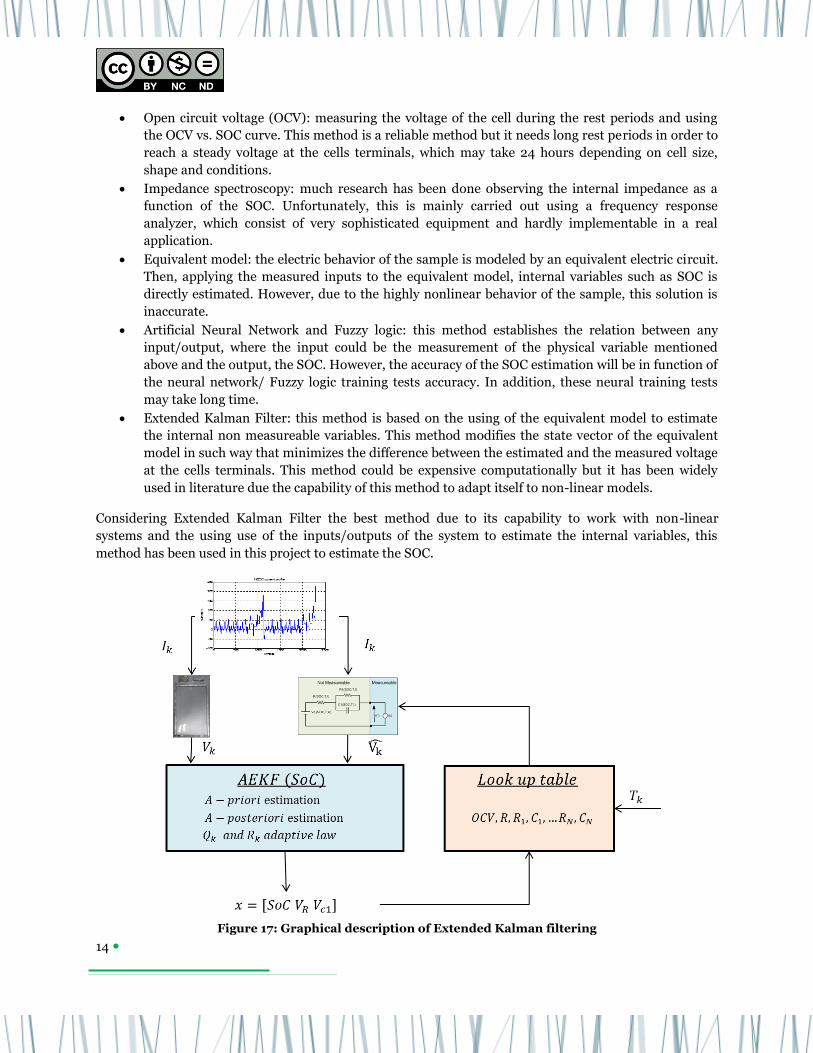
Extended Kalman Filter: this method is based on the using of the equivalent model to estimate
the internal non measureable variables. This method modifies the state vector of the equivalent
model in such way that minimizes the difference between the estimated and the measured voltage
at the cells terminals. This method could be expensive computationally but it has been widely
used in literature due the capability of this method to adapt itself to non-linear models.
Considering Extended Kalman Filter the best method due to its capability to work with non-linear
systems and the using use of the inputs/outputs of the system to estimate the internal variables, this
method has been used in this project to estimate the SOC.
Figure 17: Graphical description of Extended Kalman filtering

15
More in detail, this technique consists of three steps:
1. Initialization. All the inner state variables and covariance matrices are initialized to cope with the
initial state of lithium ion cell.
2. A-priori estimation: at this step, considering the input variables (current and temperature) and
the equivalent model, the voltage of cell is estimated.
3. A-posteriori estimation: taking into account the voltage difference between the measurement and
the estimation, the inner state vector containing SoC, Vr and Vc1 will be modified in such away to
minimize the difference the real and estimated voltage.
Additionally to the common extended Kalman filtering, an adaptive extended kalman filtering has been
used in this work. The adaptive law of the process noise covariance matrix (Qk) has been done based on
the SoC observability on the voltage measurement. As a consequence, when the observability degree of the
SoC is bigger on the voltage measurement, the SoC is adapted quicker and vice-versa.
In order to have a visual checking of the estimation, in the following set of images are shown the
comparison between the estimation (red) and the corresponding references (blue). As it can be seen, in all
cases the estimation follows the reference, which is calculated based on the coulomb counting.
Figure 18: SoC estimation under DST profile Figure 19: SoC estimation under STEPWISE
profile
Figure 20: SoC estimation under SAWTOOTH
profile Figure 21: SoC estimation under NEDC profile
0 0.2 0.4 0.6 0.8 1 1.2 1.4 1.610
20
30
40
50
60
70
80
90
100
SoC
Time [h]
SoC
[%]
0 2 4 6 8 10 12 14 16 18 200
10
20
30
40
50
60
70
80
90
100
SoC
Time [h]
SoC
[%]
0 1 2 3 4 5 6 70
10
20
30
40
50
60
70
80
90
100
SoC
Time [h]
SoC
[%]
0 0.2 0.4 0.6 0.8 1 1.2 1.4 1.6 1.840
50
60
70
80
90
100
SoC
Time [h]
SoC
[%]

16
Similarly in order to quantify the SoC estimation quality, in all cases the mean and maximum value of the
absolute error were collected and visualized in the following tables for each of the three tested cells.
Considering all the results, the maximum value of the absolute error has been always below to 1.5% and as
a consequence the SoC estimation has been validated through the mentioned extensive tests.
Table 3: SoC estimation of cell 1 with correct initialization
DST Stepwise Sawtooth NEDC
Mean Max Mean Max Mean Max Mean Max
T=10 0,09 0,19 0,62 1,43 0,25 0,63 0,02 0,04
T=25 0,01 0,04 0,11 0,27 0,07 0,23 0,02 0,06
T=45 0,02 0,07 0,10 0,46 0,27 0,52 0,03 0,08
Table 4: SoC estimation of cell 2 with correct initialization
DST Stepwise Sawtooth NEDC
Mean Max Mean Max Mean Max Mean Max
T=10 0,08 0,16 0,71 1,43 0,38 0,81 0,02 0,04
T=25 0,01 0,09 0,13 1,22 0,38 0,86 0,02 0,06
T=45 0,03 0,09 0,43 0,83 0,13 0,32 0,03 0,09
Table 5: SoC estimation of cell 3 with correct initialization
DST Stepwise Sawtooth NEDC
Mean Max Mean Max Mean Max Mean Max
T=10 0,08 0,16 0,78 1,69 0,30 0,69 0,02 0,06
T=25 0,01 0,12 0,40 0,81 0,25 0,64 0,02 0,06
T=45 0,02 0,07 0,39 0,80 0,06 0,32 0,03 0,08
17
4 Conclusions
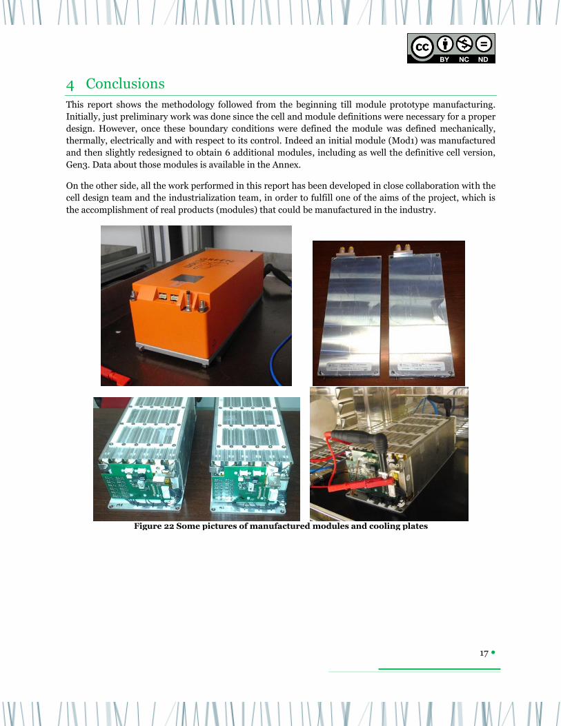
This report shows the methodology followed from the beginning till module prototype manufacturing.
Initially, just preliminary work was done since the cell and module definitions were necessary for a proper
design. However, once these boundary conditions were defined the module was defined mechanically,
thermally, electrically and with respect to its control. Indeed an initial module (Mod1) was manufactured
and then slightly redesigned to obtain 6 additional modules, including as well the definitive cell version,
Gen3. Data about those modules is available in the Annex.
On the other side, all the work performed in this report has been developed in close collaboration with the
cell design team and the industrialization team, in order to fulfill one of the aims of the project, which is
the accomplishment of real products (modules) that could be manufactured in the industry.
Figure 22 Some pictures of manufactured modules and cooling plates

18
5 Annex

19

20
6 Contacts & References
Main contact
Ik4-CIDETEC: Iosu Cendoya (Greenlion project Coordinator) [email protected]
Authors
Ik4-CIDETEC: Dr. Gorka Vertiz: [email protected]
Ik4-CIDETEC: Dr. Mikel Oyarbide: [email protected]
The authors thank the European Commission within the FP7 Projects GREENLION (Grant agreement
no. 285268) for the financial support.
References
[1] M. Oyarbide, "Development and implementation of SoC and SoH estimators for lithium based
energy storage systems," in Power electronics. vol. Phd: Mondragon Unibertsitatea, 2013.
[2] D. Doerffel, "Testing and characterization of large lithium-ion batteries for electric and hybrid
vehicles," in School of engineering sciences: University of southhamptom, 2007.
[3] M. A. Roscher and D. U. Sauer, "Dynamic electric behavior and open-circuit-voltage modeling
of LiFePO4-based lithium ion secondary batteries," Journal of Power Sources, vol. 196, pp. 331-
336, 2011.
[4] K. Jonghoon, S. Jongwon, C. Changyoon, and B. H. Cho, "Stable Configuration of a Li-Ion
Series Battery Pack Based on a Screening Process for Improved Voltage/SOC Balancing," Power
Electronics, IEEE Transactions on, vol. 27, pp. 411-424, 2012.
[5] G. Vertiz , M. Oyarbide , H. Macicior , O. Miguel , I. Cantero , P. Fernandez de Arroiabe , I.
Ulacia “Thermal characterization of large size lithium-ion pouch cell based on 1d electro-thermal
model”, Journal of Power Sources, Vol. 272, 476-484, 2014
[6] X. Bingjun, S. Yiyu, and H. Lei, "A universal state-of-charge algorithm for batteries," in Design
Automation Conference (DAC), 2010 47th ACM/IEEE, 2010, pp. 687-692.
[7] D. Andre, M. Meiler, K. Steiner, H. Walz, T. Soczka-Guth, and D. U. Sauer, "Characterization
of high-power lithium-ion batteries by electrochemical impedance spectroscopy. II: Modelling,"
Journal of Power Sources, vol. In Press, Corrected Proof, 2011.
[8] D. Andre, M. Meiler, K. Steiner, C. Wimmer, T. Soczka-Guth, and D. U. Sauer,
"Characterization of high-power lithium-ion batteries by electrochemical impedance
spectroscopy. I. Experimental investigation," Journal of Power Sources, vol. 196, pp. 5334-5341,
2011.
[9] J. A. A. Alfredo Rubio, Iker Marino, Javier Rodriguez, Jose M. Gondra, Santiago Garcia,
Sendoa Burusteta, "Caracterización y modelado de baterías de iones de litio," SAEEI, 2010.
[10] G. B. Greg Welch, An Introduction to the Kalman Filter: University of North Carolina at
Chapel Hill, 2001.
[11] Iratxe de Meatza , Oscar Miguel , Iosu Cendoya , Guk-Tae Kim , Nicholas Löffler , Nina
Laszczynski , Stefano Passerini , Peter M. Schweizer , Franca Castiglione , Andrea Mele , Giovanni
Battista Appetecchi , Margherita Moreno , Michael Brandon , Tadhg Kennedy , Emma Mullane ,
Kevin M. Ryan , Igor Cantero , Maxime Olive, “GREENLION Project: Advanced Manufacturing
Processes for Low Cost Greener Li-Ion Batteries”, Springer International Publishing, 45-60, 2015