48v100ah lithium-ion battery module for telecommunication
TRANSCRIPT

48V100Ah Lithium-ion Battery module for
telecommunication
User Manual
(V1.0)

1
Contents
1. Brief introduction ............................................................................. 3
2. Product features ................................................................................ 3
3. Product advantages ........................................................................... 4
4. Product types and technical parameters ........................................... 5
5. Environmental requirements ............................................................ 6
6. System panel functions..................................................................... 6
6.1 System panel Schematic drawing ...................................... 6
6.2 Battery output terminal ...................................................... 7
6.3 Reset key ............................................................................ 7
6.4 Communication interface ................................................... 8
6.4.1 Cascade communication interface ......................... 8
6.4.2 Upper connection communication interface ......... 9
6.4.3 Communication wire ............................................. 9
6.5 Dial switch ....................................................................... 10
6.6 LED signal introduction ................................................... 10
6.7 Dry contact ....................................................................... 12
6.8 Grounding terminal .......................................................... 13
6.9 Air switch ......................................................................... 14
6.10 Gyro anti-theft function(optional).................................. 14
7.System working principle and parameters ...................................... 15
7.1 System working principle ................................................ 15
7.2 Charge parameters............................................................ 15
7.3 Discharge parameters ...................................................... 16
7.4 System protection function and parameters ................... 16
8. System installation, uses and maintenance ..................................... 18
8.1 System installation ........................................................... 18

2
8.1.1 19 "standard rack embedded installation ............. 18
8.1.2 Scaffolding installation ........................................ 20
8.1.3 Installation of equipment cabinet type................. 23
8.1.4 Installation of wall mounting type ................ 24
8.2 System power on.............................................................. 27
8.2.1 System Activation ................................................ 27
8.2.2 System Standby ................................................... 27
8.3 Warning explanation and processing ............................... 28
8.4 Communication breakdown ............................................. 30
8.5 Protection breakdown ...................................................... 30
8.5.1 Over charge protection......................................... 30
8.5.2 Current protection ................................................ 31
8.5.3 Other breakdown ................................................. 31
8.6 Particular circumstance processing .................................. 31
8.6.1 Power outage ....................................................... 31
8.6.2 Cataclysm accident .............................................. 31
8.7 Normal operation and maintenance of LFP battery ......... 31
8.8 Stable and reliable switch power supply.......................... 32
9. Packaging transportion and storage ................................................ 32
9.1 Packaging ......................................................................... 32
9.2 Transportation .................................................................. 32
9.3 Storage ............................................................................. 33
10. Environment protection request ................................................... 33
11. Safety iessues needing attention ................................................... 33

3
1. Brief introduction
Communication LFP battery module is a high-tech product.The
product has many merits, mainly including: integration,
miniaturization, light-weight, intelligent centralism monitoring, the
battery maintenance and management, unattended, standardization
installation and easy operation, at the same time, environment friendly.
Now the product has been widely used as backup power in
telecommunication field such as access network equipment, far-end
telephone exchange, mobile telecommunication equipment,
transmission facility, satellite earth station and microwave
communication equipment, etc. At present, LFP backup battery
telecommunication series products have been put into mass production
and are widely used at home and abroad.
2. Product features
(1) The battery positive electrode is made of LFP, which has long
cycling life and good safety.
(2) The battery module adopts the high-performance BMS, which
has the protective functions of current, voltage and temperature etc..
(3) The monitoring unit automatically measures charging and
discharging current, voltage, surface temperature of the cells and
ambient temperature.
(4) The system can seamlessly turn on after the public electricity
fails. When the discharge voltage is below the warning parameter
set-up in advance, the battery will automatically send the warning

4
signal. When discharge voltage is below the protect parameter, the
battery will automatically turn off.
(5) The battery module has fine electromagnetic compatibility.
(6) Fully intelligent design, equipped with centralized monitoring
module and telemeters, telesignalisation, remote regulating, remote
control function, realizes intelligent management, and can correspond
with the far-end central monitoring center.
(7) The organic combination of the power source control technology
and the computer can monitor and control various parameters and
state in real time.
(8) Adopting the self-cooling method, the system has extremely low
noise.
3. Product advantages
(1) Realize the work directly under the primary DC
telecommunication switching power supply system with the constant
charge and discharge working mode.
(2) LFP backup battery module is the high-tech product
manufactured by Group, with proprietary intellectual property rights,
the product fills in the domestic blank,and the key technical indexes is
in the lead level of the world.
(3) LFP backup battery module is the first bulk production in
domestic, and is widely used in the telecommunication filed, with the
longest market time, biggest market quantity and good market
reaction.

5
(4) In order to satisfy Telecom Operator’s new demands on the
power-supply system, developed the integrative backup battery
module solution based on LFP battery, BMS, DC switch power
module or ups (uninterrupted power system).
(5) Higher gravimetric specific energy, during installing, there is no
extra demand for space and bearing compared with VRLA battery,
greatly reducing the cost of the area rented.
(6) Good temperature characteristics : working environment
temperature can reach -20~+60℃(recommended temperature:+15~
+35℃), which greatly reduces power consumption cost.
(7) LFP battery has excellent rate discharge performance, which
enables LFP battery with small capacity to meet large current
discharge requirements.
(8) Flexible allocation: muti-LFP battery modules in parallel, make
large capacity LFP battery module become true, not only enhance the
output power of the system, but also prolong the backup time of the
battery module.
4. Product types and technical parameters
Table 4-1 48V series of product specifications and models
Model
Nominal
voltage (DC V)
Nominal
capacity (Ah)
Maximum load
current(A)
Dimension (mm)
(width×depth×height) Weight
(kg) Remarks
48V100Ah 48 100 50 442×400×176(4U) 45 parallel system
48V100Ah 48 100 50 442×480×176(4U) 45 parallel system
48V150Ah 48 150 100 442×480×266 (6U) 65 parallel system
48V200Ah 48 200 100 442×480×354 (8U) 86 parallel system

6
Note: size deviation is ±2mm,Weight deviation is ±2Kg.
Remarks :The size of the table above is only for the battery module,
excluding cabinet, rack, rain box, etc. In order to ensure the safety,
reliability and stability of high-capacity LFP battery parallel system,
the expected capacity must be consistent with the actual capacity.
5. Environmental requirements
Ambient temperature:-20~+60℃(suggested temperature:
+15~+35℃);
Storage temperature:-40~+70℃(suggested temperature:
+15~+35℃);
Relative humidity:5%~85%RH;
Hight:not exceeding 4000m;
No conductive dust and corrosive gas place.
6. System panel functions
6.1 System panel Schematic drawing
7
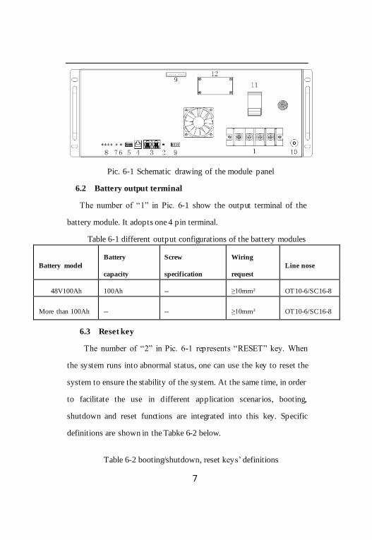
Pic. 6-1 Schematic drawing of the module panel
6.2 Battery output terminal
The number of “1” in Pic. 6-1 show the output terminal of the
battery module. It adopts one 4 pin terminal.
Table 6-1 different output configurations of the battery modules
Battery model
Battery
capacity
Screw
specification
Wiring
request
Line nose
48V100Ah 100Ah -- ≥10mm² OT10-6/SC16-8
More than 100Ah -- -- ≥10mm² OT10-6/SC16-8
6.3 Reset key
The number of “2” in Pic. 6-1 represents “RESET” key. When
the system runs into abnormal status, one can use the key to reset the
system to ensure the stability of the system. At the same time, in order
to facilitate the use in different application scenarios, booting,
shutdown and reset functions are integrated into this key. Specific
definitions are shown in the Tabke 6-2 below.
Table 6-2 booting/shutdown, reset keys’ definitions

8
No. Functions Definitions Remarks
1 booting/
activation
When battery is dormant, press this key and hold
for 3s, then the battery is activated and the LED
indicator lights up in turn. The battery is turned
into the normal working status.
2 shutdown/
dormancy
When battery is in standby or working status,
press this key and hold for 3s, the LED indicator
lights up in turn. The battery is turned into the
dormant status.
3 Reset
When the battery is in standby or working
condition, the battery is reset and the internal data
will be restored to the factory status after pressing
this key and holding for 6s.
6.4 Communication interface
6.4.1 Cascade communication interface
The number of “3” in Pic. 6-1 represents RS485 communication
ports which communicate with upper computer and the other modules
in the cascade connection among the modules. The ports adopt two
8P8C straight PCB welding telephone sockets (round pin). The
module panel is configured with two RS485 ports, which are serial
ports physically. When the battery modules are cascaded, the
communication address 000001 is defined as the master module, and
the others are defined as the slave module. The slave module can
communicate with the master module through the RS485. The master
module manages the data of each battery in the cascade system.
RS485 definition is shown in Table 6-3.
Table 6-3 The pins definition of the RS485 port
Pin Definitions
1 RS485-B

9
2,7 RS485-A
3 NC
4 NC
5 NC
6 NC
8 GND
6.4.2 Upper connection communication interface
The number of “4” in Pic. 6-1 represents RS232 communication
port, its default baud rate is 9600bps. RS232 port adopts 6P4C straight
PCB welding telephone socket (round pin). Through the RS232 port,
the master battery module can communicate with the upper computer.
When the modules are cascaded, only the master module can
communicate with the upper computer and upload data, status and
information of all of the battery module in the cascade system, which
achieves central monitoring and management, and realizes several
remote functions. RS232 communication interface definition is shown
in Table 6-4.
Table 6-4 The pins definition of the RS232 port
Pin Definitions
1,2,6 NC
3 TX
4 RX
5 GND
6.4.3 Communication wire

10
Pic. 6-2 shows the cascade communication wire connections of
RS485.
Pic. 6-2 The cascade communication wire connections of RS485
6.5 Dial switch
The number of “5” in Pic. 6-1 represents the six-bit of dial switch,
it can define the address of the module in cascade from 0 to 15. The
default address of dial code switch is 000000 (that is, the address is
"0"). If the number of battery modules in the cascade system is greater
than 15, the address code of the battery module should be set through
the software of the upper computer.
6.6 LED signal introduction
(1)Capacity signal light(SOC, green)
capacity signal light: 4 green lights, each light indicates 25%
capacity. When capacity is 100%, 4 lights are all on; when capacity is
75% ,the first light on the left extinguishs, and the other 3 lights are on;
when capacity is 50%, 2 lights on the left extinguish, and 2 lights on
the right are on; when capacity is 25%, 3 lights on the left extinguish,
and the first light on the right is on.
(2)System running indicator light(RUN, green)

11
RUN light, green, is always on during charging, and is on and off
for 0.5 second separately during discharging.
(3) Alarm indicator light(ALM, red)
ALM light, red, it’s on when the system breaks down. The
definition of specific indicator light is shown in Table 6-5:
Table 6-5 LED signal difinitions
System status
Operation status
RUN ALM LED Remark
● ● ● ● ● ●
Shut down Dormancy off off off off off off All are off
Standby
Normal flash
1
time off off off off off Standby
Alarm flash
3
times
flash3
times off off off off
Alarm and Run flash 3
times
Charge
Normal on off Indicating according to
actual capacity
According to
capacity, flash 2 times
Over
voltage protect
on off on on on on
RUN light:
Bri when the power online,
be standby when the
power is offline
Over
current protect
off on off off off off
Stop charging
and discharging
and force to sleep after no
operation for 24 hours
Discharge
Normal flash
3
times
off
Indicating according to actual capacity
According to
capacity, it’s on all the time
Alarm flash
3
times
flash3
times
Over current,
short
off on off off off off Stop charging
and
discharging

12
circuit,
reverse connection
protection
and force to
sleep after no operation for
24 hours
Low voltage
protection off off off off off off Stop
discharging
Temperatur
e
normal According to normal state to signal ---
Alarm
during charging
on
flash
3 times
Indicating according to
actual capacity
According to
capacity to flash 2 times
Alarm during
discharging
Flash 3
times
flash3
times
Indicating according to
actual capacity
According to capacity, it’s
on all the time
Protection off on off off off off
Stop charging and
discharging and force to
sleep after no operation for
24 hours
Table 6-6 LED flash mode definitions
Flash mode on off
flash 1 time 0.25s 3.75s
flash 2 times 0.5s 0.5s
flash 3 times 0.5s 1.5s
6.7 Dry contact
The number of “9” in Pic. 6-1 represents the dry contact, which is
an interface through which the battery module sends the alarm or
protection signals. When the BMS has a protection or warning signal,
the dry contact sends a switch signal through the corresponding
interface.

13
Table 6-7 Dry contact definitions
Note: Dry contact is off when BMS is in dormancy.
6.8 Grounding terminal
The number of “10” in Pic. 6-1 represents the grounding
terminal, which is used to connect to the ground. With the ground
terminal, the module can protect itself when an abnormal fault occurs
from itself and the other equipments.
DRY Definition Status
Normal Alarm
DRY1 Soc 20%-when SOC is lower than
20%,dry contact alarm NC NO
DRY2 Security feature enabled-Anti-theft
function on Dry contact in alarm NC NO
DRY3 Under voltage alarm and protection NC NO
DRY4
Charge discharge current alarm and
protection、Short circuit
protection、Reverse connection
protection
NC NO
DRY5
High and low temperature alarm
and protection of charge and
discharge
NC NO
DRY6 Alarm occurs(No action in case of
charging current limit) NC NO
DRY7 Protection and failure(No action in
case of charging current limit) NC NO

14
6.9 Air switch
The number of “11” in Pic. 6-1 represents the air switch, which
is used to disconnect the battery module and the other equipment
when the battery module is short-circuited or in over-current
condition.
6.10 Gyro anti-theft function(optional)
The BMS has a gyro anti-theft function, which can be
controlled by the host computer software to. By default, the gyro
anti-theft is activated by charging method.
The BMS PC software can set the gyro anti-theft function
activation mode. When use charging activation to activate the gyro
anti-theft function, the BMS detects that the charging current is
greater than 5A, and the time more than 30s, BMS automatically
activates the gyro anti-theft function.
After the gyroscope is fixed, the initial position state of the
gyroscope can be set by the PC software. When the gyroscope module
has an angular offset of more than 30° in any direction, After a period
of time delay (default 3s), BMS turn off the discharge MOSFET, and
lock the battery. The battery can be charged normally but cannot
discharge any more.
The locked battery can be unlocked by the host computer
software. If the gyroscope returns to the initial position after
unlocking, the battery can be charged and discharged normally. If the
gyroscope module is still offset from the initial position by 30°, the
BMS will still delay for a period of time (default 3s). and then turn off
the discharge MOSFET, cut off the output and lock the battery. The
battery can be charged normally but cannot discharge.

15
6.11 GPS module installation window
The number of “12” in Pic. 6-1 represents the GPS reserved
window,When it is necessary to install the GPS module, remove the
screws at four corners and fix the GPS module with a cable tie。
7.System working principle and parameters
7.1 System working principle
48V100Ah LFP back up battery module working principle is
shown in Pic. 7-1. The rectifier inputs AC220V power source, and
output DC -48V. Under normal grid conditions, the rectifier supplies
the working current for the load and at the same time charges the
battery module. When grid is off, the battery module supplies direct
current for the load, which achieves uninterrupted power supply.
When the battery module voltage is extremely low, the BMS will
automatically cut off power supply to extend the battery life.
Pic. 7-1Working principle diagram of LFP battery module
7.2 Charge parameters
Table 7-1 Charge parameters
48V100Ah

16
Model
Charge voltage(DC V) Charge current(A)
Mini
mum
Typical
value
Maxi
mum
48V100Ah(15S) 53.2 56.4 57.5 Charge current,≤1C3
48V100Ah(16S) 56.4 57.6 60.4
7.3 Discharge parameters
Table 7-2 Charge parameters
Model
Discharge voltage(DCV) Discharge current
(A)
Mini
mum
Typical
value
Maxi
mum
Typical
value Maximum
48V100Ah(15S) 40 48.0 53.0 0.2C3 1C3
48V100Ah(16S) 41.6 51.0 55.0 0.2C3 1C3
7.4 System protection function and parameters
Table 7-3 Protection functions and parameters
Number Protection project
Default value
15 string
system
16 string
system
1
system total voltage high
protection
and recover
Alarm value 54.00V 57.00V
Alarm recovery value 52.50V 56.00V
Protection value
54.75V 57.75V
Protection Recovery
value
50.1V 53.5V
Discharge current,total
voltage<50.1V
2
System total
voltage low protection
and recover
Alarm value 42V 42V
Alarm recovery value 43.2V 43.2V
Protection value 40V 40V
Protection Recovery
value
Charge current recovery,total voltage>43.2V
3 Short-circuit
protection Protection value Protection and alarn
4 Cell voltage Alarm value 2.5V

17
low
protection
and recover
Alarm recovery value 2.7V
Protection value 2.5V
Protection Recovery
value
Charge current recovery,
cell voltage>2.7V
5
Cell voltage high
protection
and recover
Alarm value 3.7V
Alarm recovery value 3.34V
Protection value 3.65V
Protection Recovery
value
Discharge current
recovery,cell voltage<3.34V
6
Charge over
current
protection
(no charge limited
current)
Alarm value 1.05C3A
Alarm recovery value 1.0C3A
Protection value 1.1C3A
Protection Recovery
value Discharge or manual reset
7
Discharge
over current
protection
Alarm value 1.05C3A
Alarm recovery value 1.0C3A
Protection value 1.1C3A Protection Recovery
value Charge or manual reset
8
Cell high
temperature protection
and recover
Charge high temperature protection
value
60℃
Charge high temperature recovery
value 50℃
Discharge high temperature protection
value 60℃
Discharge high
temperature recovery value
50℃
9
Cell low
temperature
protection
and recover
Charge low temperature
protection value 0℃
Charge low temperature
recovery value 5℃
Discharge low
temperature protection
value
-20℃

18
Discharge low
temperature recovery
value
-10℃
10
The
environment
temperature
protection and recovery
High temperature alarm
value 65℃
Low temperature alarm value
-20℃
High temperature
protection value 70℃
High temperature
recovery value 65℃
Low temperature
protection value -25℃
Low temperature recovery value
-20℃
Note : The table above is the default parameters, specific setting
parameters may be changed, please refer to our actual product
parameters.
8. System installation, uses and maintenance
8.1 System installation
8.1.1 19 "standard rack embedded installation
Pic. 8-1 48100 installation drawing

19
Pic. 8-2 48200 installation drawing
Pic. 8-3 48300 installation drawing

20
(1) 19″ rack mounting is recommended to be used for installation
with four M6 botls on both sides of the cabinet to fix the module on
the rack. Wall Mounting installation is also can be used.
(2) The grounding terminal at the hangers on the chassis panel
shall be grounded with a yellow-green soft wire of more than 4mm2
and good grounding should be ensured.
(3) As is shown in Pic. 8-1, 8-2, 8-3, when the 48V100Ah battery
module is connected in parallel to form a large capacity battery, firstly,
the positive terminals of each battery module are connected with the
red cable above 10mm2, and then the negative terminals of each
battery module are connected with the black cable above 10mm2 to
form a battery system. Finally, the battery system can be connected to
the switch power supply or equipment.
8.1.2 Scaffolding installation
Communication LFP battery module can be made into 48V series
product specifications and models in parallel, as shown in Table 4-1.
As shown in Pic. 8-4, the "+" and "-" terminals on the busbar of the
combined stand of the LFP battery module are connected with the "+"
and "-" terminals on the wiring terminal of the LFP battery module
respectively with the red and black wires above 16mm2 to form the
LFP battery system.

21
Pic. 8-4 (n×100)Ah Communication LFP battery system(n is the
quantity of 48V100Ah battery modules)
Main parts of the frame are shown in Pic. 8-5
1
2
3
4

22
Pic. 8-5 Main parts of the frame
No. Part Name Quantity
1 vertical column 4
2 frame fixator 2
3 Slide way According to
the order
4 Busbar 1 set
The installation processes are listed below:
Firstly, install the four vertical columns 1 into the frame fixator 2
as shown in Pic. 8-6.
Pic. 8-6 Installation Step 1
Secondly, install another frame fixator on the four vertical
columns. Install the guide rail in the area where the riveted nut is
pressed on the side of the column as shown in Pic. 8-7.

23
Pic. 8-7 Installation Step 2
Thirdly, install the bus bar on the rack for the connection and
wiring of the cable as shown in Pic. 8-8.
Pic. 8-8 Installation Step 3
Finally, install the battery on the rack and fasten the lug.
8.1.3 Installation of equipment cabinet type
Installation of rack type is a kind of indoor battery module
designed for the high demand of dust prevention situation. The system
Positive
terminal
Nega-tive
terminal

24
consists of a 19 inches standard cabinet, battery module, bus-bar and
connecting wire, etc. The height of the 19 inches standard cabinet can
be configured according to the number of the battery. The steps of
installation are just below:
(1) use more than 10 mm ² red and black soft cables to
connect battery module's +, - to the copper bus bar which is
connected in parallel in the equipment cabinet , red cable connects “+”,
and black cable connects “-“;
(2) Arrange every battery modules on the equipment cabinet
tray, use M6 bolts to fix all the hangers of the battery modules on the
holders of equipment cabinet;
(3) Grounding from the grounding hole on battery module's
panel with 4mm2 yellow-green soft cable to ensure good grounding;
(4) Using two cables to connnect the cabinet bus bars and
those of switch power supply or equipment's.
8.1.4 Installation of wall mounting type
(1) installation of battery module
As the Pic. 8-9 shows, use four M8 expansion screws to fix
two hangers on the wall, the distance between them is 445mm, and
use two M8 expansion screws to fix the triangle shelf under the
battery to support the battery.
Pic. 8-9 the sketch map of the battery module hanging on the wall
LFP
Battery
LFP Battery

25
(2) DC integral installation
As the Pic. 8-10 shows, the hangers are fixed on the wall with
four M8 expansion screw, the distance between them is 445mm. Fix
switch power supply and battery module on the hanger's bayonet nuts
with M6 bolts separately, and keep their panels upwards, then use two
M8 expansion screws to fix the triangle shelf under them as Pic. 8-10
and 8-11 show.
Pic. 8-10 The sketch of battery and rectifier installation on the wall
Pic. 8-11 The sketch of battery and rectifier wiring
Switch power Li- Fe
Battery
Switch
power

26
(3) AC integral installation
As Pic. 8-12 shows, fix the hangers on the wall with four M8
expansion screws, the distance between them is 445mm. Fix UPS and
battery module on the hanger's bayonet nuts with M6 bolts separately,
and keep their panels upwards, then use two M8 expansion screws to
fix the triangular shelf under them as Pic. 8-12 and 8-13 show.
Pic. 8-12 The sketch of battery and UPS mounted on the wall
Pic. 8-13 The sketch of battery and UPS wire connection
Li- Fe
Battery

27
Notes:
(1) When the battery module is installed in parallel, the distance
between the battery module must be no less than 20mm, and the
distance between the battery module and UPS or switch power supply
must be no less than 30mm to ensure effective heat dissipation of the
battery module, and avoid affecting the battery life.
(2) After the completion of the wall mounting installation of battery
module, dc integration system and ac integration system, a dust cover
is needed to be put above the panel to prevent dust from obstructing
fan and exhaust outlet of the equipement’s after the system works for a
long time.
8.2 System power on
Before the system is being installed, it is usually in the standby
mode. After being installed, it can be put into normal operation
through the ways below.
8.2.1 System Activation
The battery module remains dormant during storage,
transportation, or after 24 hours without power input or output. After
connecting rectifier and getting the proper input voltage, the battery
module is activated and enters into normal operation status. It should
be noted that when the battery module is dormant, the rectifier must
let its anti-reverse protection function be cancelled, so that the battery
module can be activated after ac recovers.
8.2.2 System Standby

28
If the external power source and load are removed, the battery
module will actively enter the standby state, after the battery module
is activated. In this status, the power consumption is very low, and the
RUN light on the panel flashes to indicate that the battery module is in
standby mode. After 24 hours, the battery module will automatically
enter into the dormant status, the power consumption of which is
much lower, and all of the indicator lights on the panel are completely
off.
8.3 Warning explanation and processing
In case that the battery module fails, an alarm signal will be sent
according to the fault itself. All faults have audible and visual alarm
and text log. When warning, the red warning light on the monitoring
unit is on, and a warning message is sent to the remote monitoring
center. When an alarm occurs in the system, the remote monitoring
center receives the alarm information, and maintenance personnel
should immediately check the corresponding module according to the
alarm information, find out the fault and take actions.
8.3.1 Warnings and countermeasures for cases which influence
module output
When abnormal conditions that influence module output occurs,
such as single cell over charge, over current ,low voltage protection,
temperature protection, etc, please process according to Table 8-1.
Table 8-1 Warnings and protections
Status Alarm value The warning
instructed Processing
Charge status
Cell over voltage
ALM on Stop charging , Search
breakdown

29
reason
Charge over
current ALM on
Stop charging ,
Search
breakdown
reason
Charge temperature
protection
ALM on Stop charging
Discharge
status
Discharge
over current protection
ALM on
Stop
discharging ,
Search breakdown
reason
Discharge
temperature
protection
ALM on Stop discharging
Total voltage
low voltage
protection
ALM off Charge
Cell low
voltage
protection
ALM off Charge
8.3.2 Warnings and countermeasures for cases which don’t
influence module output
If the module or its single cell voltage is low, the module will
send corresponding alarm signal. The maintenance personnel should
check the module according to the alarm information, determine the
fault type and location, and take corresponding countermeasures to
ensure the system is in the best working status and prevent the fault
extention. The phenomenon and countermeasures are shown in Table

30
8-2.
Table 8-2 Warnings without protection
Warning
Mos
-FET action
Warning
signal Countermeasure
low module
voltage
warning
None ALM flashes Stop discharge
low Cell
voltage
warning
None ALM flashes Stop discharge
8.4 Communication breakdown
The protection status and system status can be read on upper
computer software, which can help us to analyse the definite reason.
(1) When communication breakdown occurs in RS232, eliminate
it according to the following steps:
a. Check communication port;
b. Press master pack “RESET” key for 3s;
c. For a parallel system, the master pack and slave pack can be
exchanged to diagnose.
(2) When communication breakdown occurs in RS485, eliminate
it according to following steps:
a. Check communication port;
b. Press slave pack “RESET” key;
c. Exchange slave module address settings to diagnose.
8.5 Protection breakdown
8.5.1 Over charge protection
When using the standard charging voltage, the single cell
overvoltage will not appear usually, unless there is a large imbalance
among the cells. If the voltage difference are very large, the protection
31
will appear when there is cell overvoltage and the module voltage is
still low, so it is necessary to check the cell voltage.
8.5.2 Current protection
When the module current is relatively small and current
protection occurs, it is necessary to check the status indicator to check
whether the connection cable is normal.
8.5.3 Other breakdown
If there is a protection alarm and the module cannot be charged
or discharged, it is necessary to check the specific parameters such as
voltage, temperature and system status indication to determine the
fault cause.
8.6 Particular circumstance processing
8.6.1 Power outage
AC power outage is the most common situation in the module
operation. When the power outage lasts for a short period of time, dc
power supply will come from the LFP battery module.
8.6.2 Cataclysm accident
Catastrophic accidents include communications equipment
failure caused by lightning, flooding, earthquake, fire and other
disasters. The measure for these disasters which may seriously
influence communications security is to prevent and control. The
communication agency station should have the countermeasure and
the corresponding manpower physical resource to prevent these
disasters, at the same time should have the emergency act of
administration and the significant accident emergency regulations.
8.7 Normal operation and maintenance of LFP battery

32
After installation and debugging project system, if public grid
can not be accessed or the module is not activiated, please be sure to
disconnect air Circuit Breaker, and quickly connect public grid to
avoid the battery module failure.
8.8 Stable and reliable switch power supply
Please use switch power supply suitable for wide voltage
fluctuation range, or switch power supply that meets the requirements
of 110V and 220V dual standard. To avoid switch power supply
outputs instable DC voltage in the poor condition, and use reliable
quality and stable switch power supply.
9. Packaging transportion and storage
9.1 Packaging
The system adopts the overall packaging to prevent the product
in the transportation and the storage from any noxious gas, chemistry
pollution, the static electricity, moist and the mechanical damage.
Packing case indication: product name, type module, production date,
quantity and batch number.
9.2 Transportation
The products are suitable for vehicle, ship and aircraft
transportation. During transportation, the products should avoid direct
sunshine, and should be gently loaded and unloaded. The packaging
box of the product is allowed to be transported by any means of
transprtation. The battery should be lifted and put down gently to
avoid throwing, tumbling and heavy pressure. Direct rain, snow and
mechanical impact should be avoided during transportation.

33
9.3 Storage
The system shall be stored in a dry warehouse and shall not be
exposed to sun or rain. There shall be no harmful gas, inflammable
and explosive products and corrosive chemicals in the warehouse,
avoiding mechanical shock, heavy pressure and strong magnetic field
effect, and avoiding direct sunlight. The distance from the system and
the heat source shall be no less than 2m, and the packaging box shall
be at least 20cm high from the ground, and at least 50cm from the
wall, window or air inlet. Under the conditions of these provisions, the
products with storage period of more than 6 months need to be carried
out a supplementary charge, the products with storage period of more
than 12 months must be reinspected to be qualified before delivery.
10. Environment protection request
Meet RoHS request. No cadmium, hydride, fluoride and
asbestosnever, no vaporized organic compound coming out, and
package materials can be recycled.
11. Safety iessues needing attention
(1) It is strictly forbidden to immerse the battery in water or rain,
and keep the battery in a cool dry surrounding.
(2) Prohibit using and shelving the battery beside the high
temperature source.
(3) Please use the module according to the charge and discharge
parameters specified in this manual.
34
(4) Prohibit directly connecting the system with the power source
plug.
(5) Forbid discarding the battery into fire or heater.
(6) Forbid breaking up the battery and its part.
(7) Forbid to rap, stomp and throw the battery.
(8) Even if the grid is cut off, the battery module still has the
voltage output, please take care to avoid electric shock or short circuit
when using battery module.
(9) In areas with poor environmental conditions, effective
protective measures must be taken for battery module, such as good
grouding, sunshading board, rain cabinet and dust screen, to avoid
lightning, rain, snow, high temperature, dust damage battery module
and impact battery life.
(10) For being used in high temperature areas, the battery must
be used in cabinets with corresponding heat dissipation equipment
(fans or air conditioners). In low temperature areas, the battery must
be used in cabinets with corresponding heating equipment (heating
plates or air conditioners). In coastal areas, the battery must be used in
a cabinet with the corresponding salt spray protection capability.
(11) Unless otherwise specified, the charging and discharging
current for the battery module and battery module is recommended to
be set at 0.5C3.
(12) Please read the product manual carefully before installation
and application.