models ecua12 and ecua18 - airxcel ecua12 and ecua18 part no. 01706 7/2014 new manufactured by:...
TRANSCRIPT

SlimPac™ Environmental Control Unit
Operation and Installation Manual
Models ECUA12 and ECUA18
Part No. 01706 7/2014 new
Manufactured By:
Industrial Climate Engineering™ Division of AIRXCEL™, Inc.P.O. Box 5104 • Cordele, Georgia 31010-5104
2002 Hoover St • Cordele, Georgia 31015(229) 273-9558
E-mail: [email protected] • Internet: www.acice.com
The most current version of this manual can be found at www.acice.com.
ECUA12 ECUA18
2SlimPac 7/2014 new 2
How To Use This Manual This manual contains installation, troubleshooting, maintenance, warranty and application information. The information contained in this manual is to be used by the installer as a guide only. This manual does not su-persede or circumvent any applicable national or local codes.
If you are installing the SlimPac™ ECUA, first read Chapter 1 and scan the entire manual before beginning the installation. Chapter 1 contains general, descriptive information and provides an overview which can speed up the installation process and simplify troubleshooting.
If a malfunction occurs, follow this troubleshooting sequence:
1. Make sure you understand how the unit works (Chapter 1.1 - 1.4)
2. Identify and correct installation errors (Chapter 1.5 - 1.8)
3. Refer to the troubleshooting information in Chapter 3.
4. Identify defective part(s) (Chapter 2).
If you are still unable to correct the problem, contact the Factory Technical Service Department for additional assistance.
Please read the following “Important Safety Precautions” before beginning any work. Failure to follow these rules may result in death, serious bodily harm, property damage and damage to the equipment.
Important Safety Precautions1. USE CARE when LIFTING or TRANSPORTING equipment.
2. TRANSPORT the UNIT UPRIGHT. Laying it down on its side may cause oil to leave the compressor andbreakage or damage to other components.
3. TURN ELECTRICAL POWER OFF AT THE breaker or fuse box BEFORE installing or working on the equipment.LINE VOLTAGES ARE HAZARDOUS or LETHAL.
4. OBSERVE and COMPLY with ALL applicable PLUMBING, ELECTRICAL, and BUILDING CODES and ordinanc-es.
5. SERVICE may be performed ONLY by QUALIFIED and EXPERIENCED PERSONS.
* Wear safety goggles when servicing the refrigeration circuit* Beware of hot surfaces on refrigerant circuit components* Beware of sharp edges on sheet metal components* Use care when recovering or adding refrigerant
6. Use COMMON SENSE - BE SAFETY-CONSCIOUS
This is the safety alert symbol . When you see this symbol on the SlimPac unit and in the instruction manuals be alert to the potential for personal injury. Understand the signal word DANGER, WARNING and CAUTION. These words are used to identify levels of the seriousness of the hazard.
Failure to comply will result in death or severe personal injury and/or property damage.
Failure to comply could result in death or severe personal injury and/or property damage.
Failure to comply could result in minor personal injury and/or property damage.
IMPORTANT is used to point out helpful suggestions that will result in improved installation, reliability or operation.
! DANGER
! WARNING
! CAUTION

22 SlimPac 7/2014 new3
Chapter 1 Description & Specification1.1 General Description .................................................................5 1.2 RatingsandSpecifications ................................................... 61.3 General Operation ................................................................ 91.4 Electrical Diagrams ................................................................10 1.5 Controls ............................................................................... 12
Chapter 2 Installation
2.1 Equipment Inspection .......................................................... 142.2 Installation Requirements ......................................................142.3 Installation Materials ..............................................................152.4 Porting and Duct Work ..........................................................162.5 Air Flow Requirements & Ducting ..........................................162.6 Bottom Bracket Installation ....................................................172.7 Condenser Blower Orientation (SlimPac™ 18 only) ..............182.8 Mounting the Unit ..................................................................182.9 Electrical Connections ...........................................................18
Chapter 3 Start-Up3.1 Check-Out of Cooling Cycle .................................................20 3.2 Check-Out of Heating Cycle ..................................................20 3.3 Check-Out of High Temp. Alarm and/or Gas
Detection Device ...................................................................20
Contents
WARNING• If the information in these instructions are not followed exactly, a fire may result
causing property damage, personal injury or loss of life.• Read all instructions carefully prior to beginning the installation. Do not begin
installation if you do not understand any of the instructions.• Improper installation, adjustment, alteration, service or maintenance can cause
property damage, personal injury or loss of life.• Installation and service must be performed by a qualified installer or service
agency in accordance with these instructions and in compliance with all codesand requirements of authorities having jurisdiction.
INSTALLER: Affixtheinstructionsontheinsideofthebuildingadjacenttothethermostat.END USER: Retain these instructions for future reference.

4SlimPac 7/2014 new 4
Chapter 4 Troubleshooting4.1 Overview ................................................................................21 4.2 Failure Symptoms Guide .......................................................21 4.3 CompressorTroubleshooting ................................................23
Chapter 5 Maintenance 5.1 Scheduled Maintenance ........................................................24
Chapter 6 Warranty6.1 Limited Product Warranty .....................................................25
Parts List & Exploded View ..............................................................................................26
Illustrations
Figure 1a. Dimensional Data - ECUA12 ..................................... 7Figure 1b. DimensionalData-ECUA18 ..................................... 8Figure 2a. Typical Electrical Schematic - ECUA12 .....................10
2b. TypicalElectricalSchematic-ECUA18 ..................... 11Figure 3. Wall Mounting Detail ..................................................18Figure 4. ECUA12 & 18 Thermostat Wiring Diagram ...............19
Tables
Table1. SummaryRatings ......................................................... 6Table2. ElectricalCharacteristics .............................................. 6Table3. UnitLoadAmps ............................................................ 6Table4. CFM&ESP ................................................................... 6Table5. VoltageLimitations ........................................................15Table6. MaximumStaticPressure .............................................16

44 SlimPac 7/2014 new5
1.1 General DescriptionThe SlimPac™ line of environmental control units (ECUA) is designed for the telecommunication cabinet and shelter. Below are some of the features of the unit.
• The SlimPac™ ECUA is available in cooling capacities of 12,000 BTUH (ECUA12) and 18,000 BTUH(ECUA18).
• Cabinethaspowdercoatedfinishforlongtermdurability.• ECUAprotectionprovidedbylowrefrigerantpressureswitch(ECUA18only),freezestatandhigh
pressure switch.• Drycontactsareavailableforremotemonitoringoflockoutduetoahighorlowerpressure.• Lowambientoperationprovidedbycondenserfancyclecontrol(ECUA12)ormodulatingheadpressure
control (ECUA18).• 3.6kWelectricstripheatisstandard.• TheECUA12andECUA18SlimPacaresafetylistedbyETL.Bothunitsaremanufacturedandtested
to UL Std. 1995 2nd Edition and CAN/CSA-C22.2 No. 236 2nd Ed.The operating functions of the SlimPac™ ECUA line are described below.
Cooling - Mechanical cooling is provided.Heating-A3.6kWelectricresistantheater(standard)operatestoprovideheatingasrequired.
MODEL IDENTIFICATION (FollowedbyAdditionalCharacters)
Chapter 1Description and Specification
ECU A • AC A – 036Electric Heat Designator = 3.6 kW
Voltage (A) = 208/230V, 1ø, 60 Hz
AC = Air Conditioner
Nominal Cooling Capacity (12) - 12,000 BTUH (18) = 18,000 BTUH
A = R-410A Refrigerant
(ECU) Environmental Control Unit
Example:ECUA18ACA-036 = Counterflow Vertical Package ECU Nominal 1.5 tons; 208/230V, 1ø, 60 Hz; 3.6 kW Electric Heat

6SlimPac 7/2014 new 6
1.2 Ratings & Specification
Table 1. Summary Ratings
Table 2. Electrical Characteristics
Table 3. Unit Load Amps
ELECTRICHEAT 000=None 036=3.6kW
BASICMODEL VOLTAGE/PHASE/HZ
CKT#1 CKT#1
MCA MFS MCA MFS
ECUA12ACA(N) 208-230/1/60 9.3 15 19.7 20
ECUA18ACA(N) 208-230/1/60 14.9 20 20.4 25
MCA =Minimum Circuit Ampacity (Wire Sizing Amps) MFS = Max. Fuse Size or HACR circuit breaker
BASICMODEL
COMPRESSOR OUTDOORMOTOR INDOORMOTOR
TYPEVOLTS-HZ
PH RLA LRA MCCVOLTS-HZ
PH RPM FLA HPVOLTS-HZ
PH RPM FLA HP
ECUA12ACA(N) Rotary 208/230-60-1 6.3 29.0 9.8 208/230-60-1 1050 0.50 1/15 208/230-60-1 1600 0.95 1/8
ECUA18ACA(N) Scroll 208/230-60-1 9.0 48.0 14.0 208/230-60-1 825 2.00 1/3 208/230-60-1 1075 1.60 1/4
RLA = Rated Load Amps LRA = Locked Rotor Amps MCC = Maximum Continuous Current RPM = Revolutions per Minute FLA = Full Load Amps HP = Horsepower
BASICMODELNUMBER
VOLTAGEHERTZPHASE
CURRENTAMPSLOADOFRESISTIVEHEATING
ELEMENTSONLY(AMPS)TOTALMAXIMUMHEATINGAMPS(STANDARDUNIT)
ACUNIT IBM 3.6kW 3.6kW
ECUA12ACA(N) 208/230-60-1 7.75 0.95 15.00 15.95
ECUA18ACA(N) 208/230-60-1 12.60 1.60 15.00 16.60
IBM = Indoor Blower Motor
BASICMODELNUMBER
ESP
0.00 0.05 0.10 0.15 0.20 0.25
ECUA12ACA(N) 510 470 450 420 390 360
ECUA18ACA(N) 750 710 680 650 625 600
CFM = Cubic Feet/Minute Indoor Air FlowESP = External Static Pressure in Inches WG
Table 4. CFM @ External Static Pressure (Wet Coil)
66 SlimPac 7/2014 new7
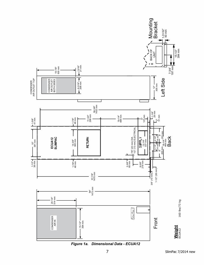
Figure 1a. Dimensional Data - ECUA12
15-1
/2"
394
mm
20-1
/4"
514
mm
58"
1473
mm
Fron
t
Bac
k
CO
ND
EN
SE
RA
IR O
UTL
ET
TOP
12"
305
mm
19-7
/8"
505
mm
8-3/
16"
208
mm
13/1
6"21
mm
Left
Sid
e
CO
ND
EN
SE
RA
IR O
UTL
ET
BO
TH S
IDE
SC
ON
DE
NS
ER
AIR
IN
7-3/
4”19
7 m
m
1-31
/32”
50 m
m
15-1
/2”
394
mm
Mou
ntin
gB
rack
etB
AC
K O
F U
NIT
ECUA
12SL
IMPA
C
1-1/
2"38
mm
15"
381
mm
1-5/
8"41
mm
1-7/
8"48
mm
1-7/
8"48
mm
14-3
/8"
365
mm
57-7
/8"
1470
mm
11-3
/4"
298
mm
56-3
/8"
1432
mm
19-1
/4"
489
mm
2-3/
8"60
mm
8-5/
8"21
9 m
m
7/8”
(22
mm
) DIA
1/2”
(13
mm
) ELE
CTR
ICA
L
2" 51 m
m
5"12
7 m
m
18-1
/4"
464
mm
1-1/
8"29
mm
3/8”
(10
mm
)
1-1/
2” (3
8 m
m)
13-1
/4"
337
mm
4-1/
2”
114
mm
4-
1/2”
11
4 m
m
8”
203
mm
8”
20
3 m
m
Wei
ght
ECU
A12
160 lbs/
73 k
g

8SlimPac 7/2014 new 8
Figure 1b. Dimensional Data - ECUA18
1/2"
(13
mm
)M
ount
ing
Hol
es(x
4)
Ret
urn
Air
Sup
ply
Air
Circ
uit
Bre
aker
Cov
er
Sig
htG
lass
Obs
erva
tion
18"
457
mm
Bac
k
Left
Sid
eFr
ont
1-1/
4"32
mm
1-1/
4"32
mm 1-1/
4"32
mm
6-1/
4"15
9 m
m
14-1
1/16
"37
3 m
m
1-11
/16"
43 m
m
56-3
/4"
1442
mm
37-7
/16"
951
mm
25-5
/16"
643
mm
2-1/
4"57
mm
9" (
229
mm
)
13-1
/4"
337
mm
15-1
/2"
394
mm
18-1
/16"
459
mm
48-1
/4"
1226
mm
58-3
/4"
1492
mm
3"76
mm
8-5/
16"
211
mm 7-3/4"
197 mm
58-1
/8"
1476
mm
15-7
/16"
392
mm
8-5/
16"
211
mm
3"76
mm
7-3/
4"19
7 m
m
40"
1016
mm
11-7
/16"
291
mm
1/2"
Low
Vol
tage
Pig
tail
3/4"
Hig
h V
olta
ge
P
igta
il
10-3
/4"
(273
mm
)
Rig
htS
ide
Con
dens
er &
C
onde
nsat
e D
rain
s14
-1/2
"36
8 m
m
2-1/
2"64
mm
Bot
tom
7-3/
4”19
7 m
m
1-31
/32”
50 m
m
15-1
/2”
394
mm
Mou
ntin
gB
rack
et
Con
dens
erIn
take
Con
dens
erA
ir O
utle
t(L
H S
ide)
*
Con
dens
erA
ir O
utle
t(R
H S
ide)
*
38"
965
mm
BA
CK
OF
U
NIT
FR
ON
T O
F U
NIT
1-1/
2"38
mm
2-1/
2" (
64 m
m)
Wei
ght
ECU
A18
247 lbs/
112.5
kg

88 SlimPac 7/2014 new9
1.3 General OperationRefrigerant Cycle (Cooling Mode)TheSlimPac™usesR-410Arefrigerantinaconventionalvapor-compressionrefrigerationcycletotransferheatfromairinanenclosedspacetotheoutside.Asupplyblowerassemblypullsindoorairacrosstheevaporator.Liquidrefrigerantpassingthroughtheevaporatorisboiledintogasbyheatremovedfromtheair.Thewarmedrefrigerant gas enters the compressor where its temperature and pressure are increased. The hot refrigerant gas condensestoliquidasheatistransferredtooutdoorairdrawnacrossthecondenserbythecondenserfan.Liquidrefrigerantisexpandedintotheevaporatorthroughthemeteringdevicetorepeatthecycle.Cooling Mode:Thecompressorandcondenserfanareenergizedwithacontactorcontrolledbya24VACpilotsignal(seeFigures2aand2b).Theoutsidefanorblowermotoriscontrolledbytheheadpressurecontrol(seeheadpressurecontrol,section1.5).Thesupplyairblowersareenergizedbytheblowerrelay.Heating Mode:Awall-mountedthermostatcontrolstheheatingcycleofmodelswhichincorporateresistanceheatingelements.Onacallforheat,thethermostatclosestheheatrelaytoenergizetheindoorblowerandtheresistance elements.

10SlimPac 7/2014 new 10
Figure 2a. Typical Electrical Schematic - ECUA12
1.4 Electrical Diagrams
1010 SlimPac 7/2014 new11
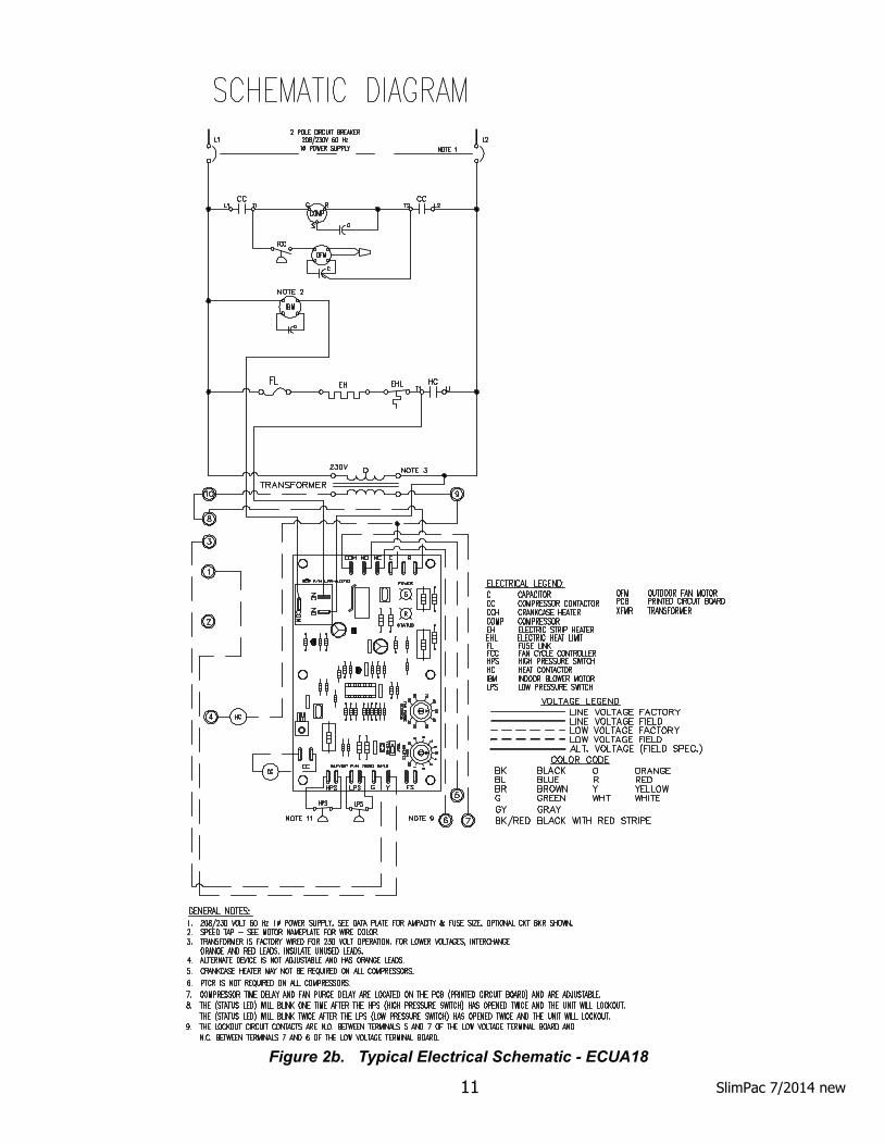
Figure 2b. Typical Electrical Schematic - ECUA18

12SlimPac 7/2014 new 12
1.5 Electronic Control Board Mode of OperationNormal24VACpowermustbecontinuouslyappliedto“R”and“C”.Uponacallforcooling“Y”andwiththehighpressureswitch(HPS)closed,thecompressorwillbeenergized.(Note:Seethedelayonmakefeature.)Thecompressorwillremainenergizedduringthe3minutetimedlowpressureby-passcycle.Ifthelowpressureswitch(LPS)isopenafterthe3minuteby-passcycle,thecompressorwillde-energize.Lock-outIfeitherofthefaultconditions(LPSorHPS)occurstwice,thecontrolboardwillenterintoandindicatethelockoutmode.Inthelockoutmode,thecompressoristurnedoff.Ifthereisacallforindoorairflow“G”,theblowerremainsenergized,thealarmoutputisenergizedandthestatusledwillblinktoindicatewhichfaulthasoccurred.Whenthelockoutconditioniscleared,theunitwillresetifthedemandforthethermostatisremovedorwhenthepowerisreset.Withthecontrolboard,theusercannowhaveeithernormallyclosedornormallyopencontactsbymovingawireonthecontrolboard.TheComPac®airconditionersarefactorywiredtobenormallyopen.Delay on BreakIfthecompressorisde-energizedduetoalossofacooling“Y”callorthefirstfault,theunitre-startwillbedelayed3minutesfromthetimethecontactorisde-energized.(Note:Thereisnodelayonbreakifthelockoutcondition is reset.)Delay on MakeOninitialpoweruponly,theunitwillwait0.03to10minutesfromthecooling“Y”callbeforeallowingthecontactortoenergize.ThedelaycanbeadjustedbytheDOMwheelontheboard.Factoryrecommendedwaitis 3 minutes.Low Pressure By-Pass TimeWhenstarting,thelowpressureswitch(LPS)faultconditionwillbeby-passedfor3minutesbeforethecontac-torisde-energized.Post PurgeUponacallforindoorairflow“G”theblowerwillenergizeimmediately.Wheninthecoolingmode,theblowerwillremainenergizedfor10to90seconds(adjustable)afterthecompressorhasbeende-energized.Thetimeperiodcanbechangedbyfanpurgewheelontheboard.Factorysettingis90seconds.LED Indicator Lights
Low Ambient ControlThe low ambient control permits cooling when outdoor ambient temperatures are low. The control uses a reverse-actinghighpressureswitchtocyclethecondenserfanmotoraccordingtoliquidrefrigerantpressureconditions.Switchclosureandfanoperationoccurswhenthepressurereaches400PSIG.Theswitchopensagainwhentherefrigerantpressurefallsto245PSIG.Therefore,theoutdoorfanalwaysstartsafterthecompressor,andit will cycle frequently during normal operation at low outdoor conditions.High Pressure SwitchThehighpressureswitchismountedonthecompressorliquidline.Itiselectricallyconnectedtoalockoutrelaywhichshutsdownthesystemiftherefrigerantpressurerisesto625PSIG.Thisprotectstheunitifairflowthroughthecondenserisblockedoriftheoutdoorfanmotorfails.Althoughthecontactsofthehighpressureswitchclosewhentherefrigerantpressurefallstoapproximately450PSIG,thesystemmustbemanuallyresetoncethelockoutrelayisactivated.Amanualresetisnecessarytopreventharmfulshort-cycling.Toresetswitch,turnprimarypoweroff,thenbackonorturnthermostatsystemswitchoff,thenbackon.
COLOR TYPE STATUS DESCRIPTION Green Power ConstantOn 24VACpowerhasbeenappliedRed Status Constant On Normal operationRed Status 1 Blink High pressure switch has opened twiceRed Status 2 Blinks Low pressure switch has opened twice

1212 SlimPac 7/2014 new13
Low Pressure SwitchThelowpressureswitchismountedonthecompressorsuctionline.Itisdesignedtoopeniftherefrigerantpressuredropsto40PSIG;itresetswhenthepressurerisesto60PSIG.Theswitchprotectstheunitifairflowthrough the indoor blower is impeded, if the blower motor fails, or if there is a loss of refrigerant.
LEDs
POST PURGE WHEEL
DELAY ON MAKE(COMPRESSOR TIME DELAY)WHEEL

14SlimPac 7/2014 new 14
2.1 Equipment InspectionConcealed Damage Inspectallcartonsandpackagesuponreceiptfordamageintransit.Removecartonsandcheckforconcealeddamage. Important: keep the unit upright at all times. Remove access panels and examine component parts. Inspectrefrigerantcircuitforfracturesorbreaks.Thepresenceofrefrigerantoilusuallyindicatesarupture.Ifdamage is apparent, immediatelyfileaclaimwiththefreightcarrier.Unitsthathavebeenturnedontheirsidesortopsmayhaveconcealeddamagetocompressormotormountsortotheoilsystem.Iftheunitisnotupright,immediatelyfileaclaimforconcealeddamagesandfollowthesesteps:
1. Setunituprightandallowtostandfor24hourswithprimarypowerturnedon.2. Attempt to start the compressor after 24 hours.3. Ifthecompressorwillnotstart,makesexcessivenoise,orwillnotpump,returntheunittothefreight
carrier.
2.2 Installation RequirementsGeneral1. Inspectunitforcompleteness.Checkformissingparts(e.g.hardware).Refertotheinstallationkitinforma-
tion in section 2.3. 2. Removeaccesspanelsandcheckforloosewires.Tightenscrewconnections.3. Completeandmailthewarrantyregistrationcard.Youmustconsiderallofthefollowingwhenchoosingtheinstallationsite:1. Evaporator Condensate Drainage. Condensate produced during operation must be discharged from the
evaporatorpanthroughtheprimaryand/orsecondarydrainhoses.Makesurethecondensatelinesarefreeofanyrestrictions.Condenser Pan Drainage.Waterfromrainwillaccumulateinthecondenserdrainpanandshoulddischargefromthecondenserpanthroughthedrainline.Makesurethedrainholeandlinearenotrestrictedduetotrash or crimping.
2. Placement.A) Place the unit in a shaded area, if possible.B) Installitabovegroundforprotectionagainstflooding.C) Makesuretheairflowfromthecondensersectionandventhoodarenotimpededbyshrubberyorother
obstructions.D) Makesuretheunitisinstalledlevel.
Chapter 2Installation
WARNING Failure to observe and follow Warnings and Cautions and these Instructions could
result in death, bodily injury or property damage. Read this manual and follow its instructions and adhere to all Cautions and Warnings in the manual and on the ICE unit.

1414 SlimPac 7/2014 new15
2.3 Installation MaterialsInstallation Kits The SlimPac™ ECUA is shipped with a bottom mounting bracket kit.Ifyouhavenotyetunpackedtheunit, follow the instructions in section 2.1. Bottom Mounting is One 0.080 Aluminum L-Shaped Bracket:
One0.080AluminumBottomBracket(shipsmountedonunit)Other Optional Equipment:Thepackagemayincludeotherfactory-supplieditems(optional)asfollows:
PART # DESCRIPTION
50123 Digitalthermostat.1stageheat,1stagecool.7dayprogrammable.Fanswitch:Auto&On.Auto-changeover.Keypadlockout.Non-volatileprogrammemory.
50186 One stage cool, one stage heat. Auto-changeover. S/07529 LL357-D4,Lead/LagControllerwithThermostatandSub-Base;ControlsTwoA/CUnits.S/04581 CommStat 3™ Lead/Lag Controller.50131 InternalThermostatw/TemperatureRangeof60°Fto140°F,Differentialof5°F.80685 AdjustableAluminumSupplyGrille,5"x13-1/4"80680 AluminumReturnFilterGrille,12"x14"40388 ECUA18 Condenser Discharge40389 ECUA18CondenIntakeGrille
Additional Items Needed:Additional hardware and miscellaneous supplies (not furnished by ICE) are needed for installation. For example,thelistbelowcontainsapproximatequantitiesofitemstypicallyneededformountingaunitonaconcrete,fiberglassorsteelframestructure.Concreteandfiberglassstructureshavedifferentrequirements.
3. Clearances:The units are designed to operate when either the left or right side (not both) on the condenser section areblocked.Theopensideandthetopshouldhaveaminimumclearanceof24".Therearoftheunitshouldbe60"fromanyobstructiontoairflow.
4. Codes:Make sure your installation conforms to all applicable electrical, plumbing, building, and municipalcodes.
5. Electrical Supply:Thepowersupplymusthavetheappropriatevoltage,phase,andampacityforthemodelselected.Voltagemustbemaintainedaboveminimumspecifiedvalueslistedbelow.RefertotheElectrical Ratings (section1.2)forampacityrequirements.
Table 5. Voltage Limitations
ELECTRICAL RATING DESIGNATORS ACNOMINAL VOLTAGE 208/230PHASE 1MINIMUM VOLTAGE 197MAXIMUM VOLTAGE 253

16SlimPac 7/2014 new 16
• Silicone Sealertosealaroundcracksandopenings.Sealalltopmountingholesnotusedandprovidea seal at the top of the unit where it meets the building to eliminate water intrusion. Provide a completeperimetersealbetweentheunitandcabinet.Theinsulationthatisfactoryinstalledaroundthesupplyandreturnairopeningsisanairsealonly.Itisnotawaterorweatherseal.
• Use appropriate electrical supplies such as conduit, electrical boxes, fittings, wire connectors, etc.• High voltage wiresizedtohandletheMCA(minimumcircuitampacity)listedonthedataplateandin
the Electrical Ratings table in section 1.2.• Over-Current Protection DevicesizedinaccordancewiththeMFS(maximumfusesize)listedonthe
unit data plate and in the Electrical Ratings table in section 1.2.
WARNING
FIRE HAZARDImproper adjustment, alteration, service, maintenance or installation could cause serious injury, death and/or property damage.Installation or repairs made by unqualified persons could result in hazards to youand others. Installation MUST conform with local codes or, in the absence of local codes, with codes of all governmental authorities have jurisdiction.The information contained in this manual is intended for use by a qualified serviceagency that is experienced in such work, is familiar with all precautions and safety procedures required in such work, and is equipped with the proper tools and test instruments.
2.4 Porting and Duct Work General InformationNote:Thefollowinginstructionsareforgeneralguidanceonly.Duetothewidevarietyofinstallationpossibili-ties,specificinstructionswillnotbegiven.Whenindoubt,followstandardandacceptedinstallationpractices,or contact ICE for additional assistance.
Minimum Air Flow RequirementsTheductsystemmustbeengineeredtoassuresufficientairflowthroughtheSlimPac™ECUA,evenunderadverseconditionssuchasdirtyfilters,etc.SeetablebelowandTable4,CFM at External Static Pressure (Wet Coil) in section 1.2.
Table 6. Maximum Static Pressure
2.5 Air Flow Requirements & DuctingDucting Extensionlengthshouldbecutflushwiththeinsidewallforapplicationswithoutductwork.Applicationsusingductworkshouldbedesignedandinstalledinaccordancewithallapplicablesafetycodesand standards. ICE strongly recommends referring to the current edition of the National Fire ProtectionAssociation Standards 90A and 90B before designingandinstallingductwork.Theductsystemmustbeengi-neeredto insuresufficientairflowthroughtheunittopreventover-heatingoftheheaterelement.Thisincludespropersupplyductsizing,sufficientquantityofsupplyregisters,adequatereturnandfilterarea.Ductworkmust
MODEL MAXIMUM TOTAL STATIC MINIMUM FILTER AREA0.25 2.58 SQ. FT.0.25 2.58 SQ. FT.

1616 SlimPac 7/2014 new17
beofcorrectmaterialandmustbeproperlyinsulated.Ductworkmustbefirmlyattached,securedandsealedtopreventairleakage.Donotuseductlineroninsideofsupplyductwithin4feetoftheunit.Galvanizedmetalductextensionsshouldbeusedtosimplifyconnectionstoductworkandgrilles.Usefabricbootstopreventthetransmissionofvibrationthroughtheductsystem.ThefabricmustbeU.L.rated(UL-181)toaminimumof197°F.
2.6 Bottom Bracket InstallationWall Openings MeasurethedimensionsofthesupplyandreturnportsontheSlimPac™ECUA.Cutopeningsintheenclosurewallforthesupplyandreturnducts.Makethesupplyopeningsone inch larger thantheductflangesontheunit.Theoneinchclearancemustbemaintainedonallsidesofthesupplyducttocombustiblematerialforthefirstthreefeetoftheduct.
1. Remove and discard the shipping crate attached to the unit.2. TheSlimPac™ECUAisshippedwiththebottombracketseasilyremoved.3. RefertoFigure3.Attachthebottomsupportbrackettothewallusingappropriatehardware.
Figure 3. Wall Mounting Detail

18SlimPac 7/2014 new 18
2.7 Condenser Blower Orientation (SlimPac™ 18 only)ThecondenserblowerintheSlimPac™18canberotated180°toallowonesideoftheunittobeflushagainsta splice chamber or similar structure. The blower must be rotated PRIOR to mounting the unit on the building. To rotate the blower:
• Remove the six screws that hold the top panel in place and remove the top panel.• Removethesquareblankoffplateoppositetheblowerdischarge.• Remove the three screws that hold the blower in place.• Facingthesupplyandreturnopenings,rotatetheblowercounterclockwiseandsecureinplacewiththe
three screws.• Installsquareblankoffplateoppositetheblowerdischarge.
2.8 Mounting the Unit1. Usinganappropriateandsafeliftingdevice,settheSlimPac™ECUAonthebottomsupportbracketmounted
onthewall.Youmuststabilizetheunitonthebracketwiththeliftingdeviceorbysomeothermeans-thebracketaloneisnotsufficient.
2. Makesurethattheductflangesareproperlyalignedwiththewallopening.Adjustasnecessary.3. Applysiliconesealertotheperimeteroftheunit,aroundthesupplyandreturnflanges,andovertheunused
mounting holes.4. Bolt the top and bottom of the unit to the shelter wall.5. Applyasiliconebeadtothetopandperimeterwheretheunitmeetsthecabinet.6. Pull the power and control wires through the conduit into the cabinet.
2.9 Electrical Connections
WARNING
ELECTRICAL SHOCK HAZARDFailure to follow safety warnings exactly could result in serious injury, death, and/or property damage.Turn off electrical power at fuse box or service panel BEFORE making any electrical connections and ensure a proper ground connection is made before connecting line voltage.
IMPORTANT !All electrical work must meet the requirements of local codes and ordinances. Workshouldbedoneonly byqualifiedpersons.The SlimPac™ units are provided with labeled power leads and an eight-conductor thermostat cable.
High Voltage Wiring The high voltage wire provided with the SlimPac™ ECUA can be replaced to eliminate wire nut connections. L1,L2andgroundwirescanbereplacedatthecircuitbreaker.Thepowersupply(s)shouldhavethepropervoltage,phase,andampacityfortheselectedmodels.
Low Voltage (Control) Wiring 1. Mount the sub-base on a level plane. Use a line and surface level. Connect the thermostat wire as shown
in Figure 4.2. Attachthethermostatassemblytothesub-base.Checkstageoneanticipatorsettings-shouldread.40.

1818 SlimPac 7/2014 new19
Figure 4. Thermostat Wiring Diagram
NOTE:BlackandbluewiresontheECUA12andblack,blueandorangewiresontheECUA18terminalblockaredrycontactswhichcanbeusedforremotesignalingintheeventofequipmentshut-offonloworhigh pressure limits.
3. Unitshutdownisavailablefromafieldprovidedalarmdevice;i.e.,smokealarm,firestat.Installanormallycloseddevicebetweenredwireandthe"R"terminalonthethermostat.Thiswilldisablethe24Vcontrolvoltage. See Figure 4.
NOTE: THE INTERNAL TRANSFORMER IS NOT DESIGNED TO POWER OTHER EXTERNAL DEVICES.

20SlimPac 7/2014 new 20
3.1 Check-Out of Cooling CycleProcedure:1. Set the cooling temperature set point on the wall thermostat to a point higher than the ambient temperature.
Set the heating temperature set point to a temperature that is lower than the ambient.2. SetthethermostatsystemswitchintheAUTOposition.Nothingshouldoperateatthistime.3. Setthetimedelayinthecontrolboxtothreeminutes..4. Slowlylowerthethermostat'scoolingtemperaturesetpointuntiltheswitchcloses.Theindoorfanshould
operate.Oncetheindoorfanturnson,allowapproximatelythreeminutesforthecompressortostart..Notethattheoutdoorfanmaynotcomeonimmediately,becauseitiscycledbyrefrigerantpressures.Iftheunitfailstooperate,refertothetroubleshootinginformationinChapter4.Follow the same procedure for additional units.
3.2 Check-Out of Heating Cycle Procedure: (Applies only to units with resistance elements)1. Tostopthecooling,slowlyraisethecoolingtemperaturesetpointtoatemperaturehigher than the ambi-
ent.2. Raise the heating temperature set point to a setting which is higher than the ambient temperature. The
blowerandelectricheatshouldimmediatelycycleon.3. Movethesystemswitchtothe"OFF"position.Allfunctionsshouldstop.
3.3 Check-Out of High Temp. Alarm and/or Gas Detection DeviceProcedure: 1. Setthesystemtooperateinthecoolingmodeasdescribedinsection3.1above.Triggerthenormallyclosed
external device (high temperature alarm or gas detection device) to open and the ECUA should shut off.2. Setthesystemtooperateintheheatingmodeasdescribedinsection3.2above.Triggerthenormallyclosed
external device to open and the ECUA should shut off.
Chapter 3Start-Up

2020 SlimPac 7/2014 new21
4.1 Overview
WARNING
Failure to follow these instructions could result in death, severe personnel injury and/or property damage.AcomprehensiveunderstandingoftheoperationoftheSlimPac™ECUAisaprerequisitetotroubleshooting.Please read the Chapter 1 for basic information about the unit. ICE SlimPac™ECUsare thoroughly testedbefore theyareshippedfromthefactory. Ofcourse, it ispos-siblethatadefectmayescapeundetected,ordamagemayhaveoccurredduringtransportation.However,thegreatmajorityofproblemsresultfrominstallationerrors.IfyouexperiencedifficultieswiththeSlimPac™ECUA,pleasereviewtheinstallationstepsinChapter2.Itmaybehelpfultogetanotherpersontoreviewandcheckthemwithyou.Muchtimecanbesavedbytakingathoughtfulandorderlyapproachtotroubleshooting.Startwithavisualcheck-arethereloosewires,crimpedtubing,missingparts,etc?Begindeeperanalysisonlyaftermakingthisinitial inspection.The troubleshooting information in this manual is basic. The troubleshooting section contains problem/solution chartsforgeneralproblems,followedbyacompressorsection.Noteveryproblemcanbeanticipated.Ifyoudiscoveraproblemthatisnotcoveredinthismanual,wewouldbeverygratefulifyouwouldbringittotheattentionofourservicedepartmentforincorporationinfuturerevi-sions.Asalways,pleaseexercisecautionandgoodjudgementwhenservicingtheSlimPac™ECUA.Useonlysafeandprovenservicetechniques.Userefrigerationgoggleswhenservicingtherefrigerationcircuit.Therefrigerantcircuithashotsurfaces,andtheelectricalvoltagesinsideoftheunitmaybehazardousorlethal.SERVICE MAY BE PERFORMED ONLY BY QUALIFIED AND EXPERIENCED PERSONS.
4.2 Failure Symptoms GuidePROBLEM / SYMPTOM LIKELY CAUSE(S) CORRECTION
A. Unit does not run.
NOTE: An internal anti-short-cycle timer will prevent the unit from starting for .2 to 8 minutes following start-up.
1. Check power supply for adequate phaseand voltage. Check wiring to unit andexternal breakers or fuses.
2. Check internal circuit protectiondevices for continuity.
3. Check operation of wall-mounted thermo-stat.
4. Check terminal 5 and 7. If closed thenreset limit switch. See section 1.6.
5. Check for loose wiring. Checkcomponents for failure, especially timedelay relay.
1. Power supply problem.
2. Blown internal fuse or breaker.
3. Shut off by external thermostat orthermostat is defective.
4. Unit off on high pressure limit, low pressurelimit (ECUA18 only) or freeze stat.
5. Internal component or connectionfailure.
Chapter 4Troubleshooting
IMPORTANT

22SlimPac 7/2014 new 22
PROBLEM / SYMPTOM LIKELY CAUSE(S) CORRECTION
1. Add additional units for greater capacity.
2. Check for proper charge.
3. Check internal components, especiallycompressor for proper operation.
4. Check air filter(s). Check blower operation.Remove airflow restriction.
1. Check blower assembly for proper operation.Look for airflow restrictions, e.g., the air filter.Check blower motor and condenser fan.
2. Check for blockage or restriction, especiallyfilter drier and capillary tube assembly.
3. Evacuate and recharge to factoryspecifications.
4. Check limit cut-out pressures. Control is setto actuate at 40 PSIG (low pressure)* and625PSIG (high pressure).
1. Note electrical requirements in Chapter 2 andcorrect as necessary.
2. Check field wiring for errors.
3. Check wiring in unit. See wiring and schematic diagrams. Test components (especially thecompressor) for shorts.
4. Note voltage range limitations specific to thecompressor troubleshooting section.
1. Check for clog or restriction.
2. Check pan for leak or blockage.
3. Level unit.
1. Unit undersized for the job.
2. Loss of refrigerant.
3. Component failure.
4. Dirty filter or reduced airflow.
1. Loss or restriction of airflow.
2. Restriction in refrigerant circuit.
3. Refrigerant overcharge (following fieldservice)
4. Defective pressure control.
1. Inadequate circuit ampacity.
2. Short, loose or improper connection in fieldwiring.
3. Internal short circuit. Loose or improper connection(s) in unit.
4. Excessively high or low supply voltage.
1. Obstruction in condensate line.
2. Obstruction or leak in condensate pans.
3. Unit is not level.
B. Unit runs for long periods or continuously; cooling is insufficient.
C. Unit cuts out or cycles on high/low pressure limit.*
*SlimPac™ 18 ECUA only
D. Unit blows fuses or trips circuit breaker.
E. Water on floor near unit.

2222 SlimPac 7/2014 new23
PROBLEM / SYMPTOM LIKELY CAUSE(S) CORRECTION
1. Check resistance element(s) for continuity.
2. Check continuity across thermal limit switch.
3. Check relay for proper operation. Replaceif defective.
1. Defective heating element(s).
2. Thermal limit open.
3. Defective heater relay.
F. No space heating or reduced heating (units equipped with resistance elements).
4.3 Compressor TroubleshootingNOTE:Itisimportanttoruleoutothercomponentfailuresbeforecondemningthecompressor.The following electrical tests will aid diagnosis: 1. Start-Up Voltage: Measure the voltage at the compressor contactor during start-up. The voltage must
exceedtheminimumshowninTable6,orcompressorfailureislikely.Alowvoltageconditionmustbecorrected.
2. Running Amperage:Connectaclip-ontypeammetertothe(common)leadtothecompressor.Turnonthesupplyvoltageandenergizetheunit.Thecompressorwillinitiallydrawhighamperage;itshouldsoondroptotheRLAvalueorless.Iftheamperagestayshigh,checkthemotorwindingresistances.NOTE:Feelthetopofthecompressortoseeifithasoverheated.Ifitishot,theinternaloverloadmaybeopen.Youmayhavetowaitseveralhoursforittoreset.
3. Motor Winding Resistances:Usingadigitalvolt-ohmmeter(VOM),measuretheresistanceacrossthecompressor windings as shown below.
Resistancecanbemeasuredasshownabove.Anydeviationfromabovevaluescouldindicateadefectivecompressor.
4. High Voltage/Insulation Test:Testinternalleakagewithamegohmeter.Attachoneleadtothecompressorcase on a bare metal tube and to each compressor terminal to test the motor windings. A short circuit at highvoltages indicates a motor defect. Do not do this test under vacuum.
C
S R
R2 R1
R3
SINGLEPHASE R3 > R2 > R1
R3 = R2 + R1

24SlimPac 7/2014 new 24
ICE stronglyrecommendsthattheenvironmentalcontrolunitsbeservicedaminimumoftwiceayear,onceprior to the heating season and once prior to the cooling season. At this time the filters, evaporator coil,condenser coil, the cabinet, and condensate drains should be serviced as described below. Also at this time, theenvironmentalcontrolunitsshouldbeoperatedinthecoolingandheatingcyclesasdescribedinChapter3,Start-Up.Inadditiontothisseasonalcheck-out,theSlimPac™ECUAshouldbemaintainedasfollows:
Air FilterReplacetheairfilterwheneveritisvisiblydirty.
EvaporatorIftheevaporatorbecomescloggedordirty,itmaybecleanedbycarefulvacuumingorwithacommercialevapora-torcleaningspray.DONOTuseasolventcontainingbleach,acetone,orflammablesubstances.SwitchtheunitOFFattheFUSEorBREAKERBOXbeforecleaning.Becarefulnottowetanyoftheelectricalcomponents.Be sure the unit has dried before restarting.
CondenserPeriodicallyinspecttheoutdoorcondensercoilandthecabinetairreliefsfordirtorobstructions.Removefor-eignobjectssuchasleaves,paper,etc.Ifthecondensercoilisdirty,itmaybewashedoffwithacommercialsolventintendedforthispurpose.TURNOFFPOWERBEFORECLEANING!Besurethatallelectricalcomponentsarethoroughlydrybeforerestor-ing power.
CabinetThecabinetmaybecleanedwithaspongeandwarm,soapywateroramilddetergent.Donotusebleach,abra-sive chemicals or harmful solvents.
DrainsRegularlychecktheprimaryandsecondarycondensatedrains.Thesecondarydrainhasastandpipe.Anobstruc-tion will force water to dump into the middle of the unit and drain out the sides of the SlimPac™ unit, causing discolorationofthesidepanels.Ifdiscolorationisnoted,servicethedrains.Ifacommercialdrainsolventisused,flushoutthedrainpanandsystemwithplentyoffreshwatertopreventcorrosion.
LubricationOiling of the condenser fan motor or the evaporator blower motor is not recommended.
5.1 Scheduled Maintenance
Chapter 5Maintenance
2424 SlimPac 7/2014 new25
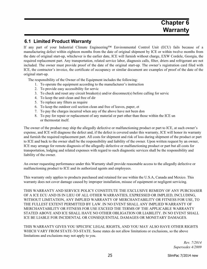
6.1 Limited Product Warranty
Chapter 6Warranty
If any part of your Industrial Climate Engineering™ Environmental Control Unit (ECU) fails because of a manufacturing defect within eighteen months from the date of original shipment by ICE or within twelve months from the date of original start-up, whichever is the earlier date, ICE will furnish without charge, EXW Cordele, Georgia, the required replacement part. Any transportation, related service labor, diagnosis calls, filter, driers and refrigerant are not included. The owner must provide proof of the date of the original start-up. The owner’s registration card filed with ICE, the contractor’s invoice, the certificate of occupancy or similar document are examples of proof of the date of the original start-up.
The responsibility of the Owner of the Equipment includes the following:1. To operate the equipment according to the manufacturer’s instruction2. To provide easy accessibility for servic3. To check and reset any circuit breaker(s) and/or disconnect(s) before calling for servic4. To keep the unit clean and free of dir5. To replace any filters as require6. To keep the outdoor coil section clean and free of leaves, paper, et
To pay the charges incurred when any of the above have not been don7.To pay for repair or replacement of any material or part other than those within the ICE un8.or thermostat itself.
The owner of the product may ship the allegedly defective or malfunctioning product or part to ICE, at such owner’s expense, and ICE will diagnose the defect and, if the defect is covered under this warranty, ICE will honor its warranty and furnish the required replacement part. All costs for shipment and risk of loss during shipment of the product or part to ICE and back to the owner shall be the responsibility and liability of the owner. Upon written request by an owner, ICE may arrange for remote diagnosis of the allegedly defective or malfunctioning product or part but all costs for transportation, lodging and related expenses with regard to such diagnostic services shall be the responsibility and liability of the owner.
An owner requesting performance under this Warranty shall provide reasonable access to the allegedly defective or malfunctioning product to ICE and its authorized agents and employees.
This warranty only applies to products purchased and retained for use within the U.S.A, Canada and Mexico. This warranty does not cover damage caused by improper installation, misuse of equipment or negligent servicing.
THIS WARRANTY AND SERVICE POLICY CONSTITUTE THE EXCLUSIVE REMEDY OF ANY PURCHASER OF A ICE ECU AND IS IN LIEU OF ALL OTHER WARRANTIES, EXPRESSED OR IMPLIED, INCLUDING, WITHOUT LIMITATION, ANY IMPLIED WARRANTY OF MERCHANTABILITY OR FITNESS FOR USE, TO THE FULLEST EXTENT PERMITTED BY LAW. IN NO EVENT SHALL ANY IMPLIED WARRANTY OF MERCHANTABILITY OR FITNESS FOR USE EXCEED THE TERMS OF THE APPLICABLE WARRANTY STATED ABOVE AND ICE SHALL HAVE NO OTHER OBLIGATION OR LIABILITY. IN NO EVENT SHALL ICE BE LIABLE FOR INCIDENTAL OR CONSEQUENTIAL DAMAGES OR MONETARY DAMAGES.
THIS WARRANTY GIVES YOU SPECIFIC LEGAL RIGHTS, AND YOU MAY ALSO HAVE OTHER RIGHTS WHICH VARY FROM STATE-TO-STATE. Some states do not allow limitations or exclusions, so the above limitations and exclusions may not apply to you.
Rev. 7/2014 Supersedes 4/2009

26SlimPac 7/2014 new
EXPLODED VIEWS AND PARTS LISTS
Current parts lists and exploded views of the unit can be found on our web site at www.acice.com. Click on the Service and Parts in the menu on the left hand side of the Home page. From the drop down menu, select Exploded Views. Once here, you can select your air conditioner or heat pump. The units are grouped by model and by the refrigerant – R-22 or R-410A.