quick reference guide p.c. board/wall thermostat ... - airxcel · a division of airxcel, inc. p.o....
TRANSCRIPT
QUICK REFERENCE GUIDE
P.C. BOARD/WALL THERMOSTAT
FOR
6535*, 6537*, 6538*
TWO TON PACKAGED
HIGH EFFICIENCY
HEAT PUMPS
Note: This manual may also be used for 6535-871 series heat pumps if the 6535*3209 Replacement P.C. Board Kit has been installed in the unit.
RV ProductsA Division of Airxcel, Inc.
P.O. Box 4020Wichita, KS 67204
1-877-430-8084 (Service Center Locator)1-316-832-4357 (Dealer Only Technical Help)
Web: www.rvcomfort.comSupport: [email protected]
Sales: [email protected]
1976B437 (3-06)

TABLE OF CONTENTS
I. Wall Thermostat Installation and Operating Instructions - 6535*335 . . . . . . . . . . . . . . . . . . . . . 3Wall Thermostat Installation and Operation Instructions - 6536*335 . . . . . . . . . . . . . . . . . . . . . 5
II. Heat Pump Operation Sequence - Cooling Mode . . . . . . . . . . . . . . . . . . . . . . . . . . . . . . . . . . . . . 8
III. Heat Pump Operation Sequence - Heating Mode . . . . . . . . . . . . . . . . . . . . . . . . . . . . . . . . . . . . . 9
IV. 6535*320 Printed Circuit Board Function Chart . . . . . . . . . . . . . . . . . . . . . . . . . . . . . . . . . . . . . . 11Printed Circuit Board 9-Pin Thermostat Plug Connector . . . . . . . . . . . . . . . . . . . . . . . . . . 12Printed Circuit Board Indoor Blower Section . . . . . . . . . . . . . . . . . . . . . . . . . . . . . . . . . . . 13Printed Circuit Board Compressor Section . . . . . . . . . . . . . . . . . . . . . . . . . . . . . . . . . . . . . 14Printed Circuit Board Freeze Sensor Section . . . . . . . . . . . . . . . . . . . . . . . . . . . . . . . . . . . . 15Printed Circuit Board Outdoor Blower Section . . . . . . . . . . . . . . . . . . . . . . . . . . . . . . . . . . 16Printed Circuit Board Heating (Heat Pump) Section. . . . . . . . . . . . . . . . . . . . . . . . . . . . . . 17
V. Wiring Diagram - 6535 “A” 871 Series Two Ton High Efficiency Packaged Heat Pump. . . . . . . 18Wiring Diagram - 6535-671, 6535A671, 6535B871, 6537 & 6538 Series Two Ton High
Efficiency Packaged Heat Pump. . . . . . . . . . . . . . . . . . . . . . . . . . . . . . . . . . . . . . . . . . . . . 19

3
I. WALL THERMOSTAT INSTALLATION ANDOPERATING INSTRUCTIONS
6535*335 Thermostat (Winnebago Only)
The display indicates room temperature and the word ROOM is shown on the LCD until the temperature selector is pressed;at which time the display temporarily indicates the setpointtemperature and the word SET is shown on the LCD. Eachtime the UP arrow is pressed, the setpoint will increase. Eachtime the DOWN arrow is pressed, the setpoint will decrease. Once the temperature selector button is no longer pressed fora few seconds, the room temperature will again be displayed,and the word ROOM will be displayed on the LCD.
In electric heat mode, if the heat pump is unable to satisfy thethermostat, DIFF will flash on the thermostat LCD when 2nd
stage heating is required to satisfy the thermostat.
In gas heat mode, the gas furnace will provide the only sourceof heat and the heat pump is locked out.
NOTE
The temperature displays in degrees Fahrenheit as a factory setdefault (See Figure 2). To display in degrees Celsius, move thejumper marked “F” and “C” to bridge between middle pin andposition “C”, then cycle 12 volt power off and then back on.
6535*335 Thermostat Wiring

4
6535*335 2-Stage Heat Pump Thermostat Operation Table
ModeSwitch
Fan ModeSwitch
Fan SpeedSwitch
Calling Operation
1 Cool Auto Lo No No functions occur in this mode
2 Cool Auto Lo Stage 1 1 Degree Above Set
ID fan low, compressor #1 and OD blower lowcycle as needed
3 Cool Auto Lo Stage 22 Degrees Above Set
ID fan low, compressors #1 and #2 and OD blowerhigh cycle as needed
4 Cool On Lo No ID fan low continuous
5 Cool On Lo Stage 11 Degree Above Set
ID fan low continuous, compressor #1 and ODblower low cycle as needed
6 Cool On Lo Stage 22 Degrees Above Set
ID fan low continuous, compressors #1 and #2and OD blower high cycle as needed
7 Cool Auto Hi No No functions occur in this mode
8 Cool Auto Hi Stage 11 Degree Above Set
ID fan high, compressor #1 and OD blower lowcycle as needed
9 Cool Auto Hi Stage 22 Degrees Above Set
ID fan high, compressors #1 and #2 and ODblower high cycle as needed
10 Cool On Hi No ID fan high continuous
11 Cool On Hi Stage 11 Degree Above Set
ID fan high continuous, compressor #1 and ODblower low cycle as needed
12 Cool On Hi Stage 22 Degrees Above Set
ID fan high continuous, compressors #1 and #2and OD blower high cycle as needed
13 Off Auto Lo or Hi No No functions occur in this mode
14 Off On Lo No ID fan low continuous
15 Off On Hi No ID fan high continuous
16 Gas Heat Auto or On Lo or Hi No No functions occur in this mode
17 Gas Heat Auto or On Lo or Hi Stage 1 Heater will be energized to run
18 Gas Heat Auto or On Lo or Hi Stage 2 There is no provision for 2nd stage heat whenoperating in the gas heat mode
19 Elec Heat Auto or On Lo or Hi No No functions occur in this mode
20 Elec Heat Auto or On Lo or Hi Stage 1 Heat pump will run ID fan high, both compressors,OD fan high and both reversing valves
21 Elec Heat Auto or On Lo or Hi Stage 2 Heat pump will run ID fan high, both compressors,OD fan high and both reversing valves plus theheater will be energized to run

5
INSTALLATION AND OPERATING INSTRUCTIONSFOR 6536*335*
2 STAGE HEAT PUMP WALL THERMOSTAT
APPLICATION
The 6536*335* thermostat is intended for use with an RVProducts 2 stage heat pump.
The thermostat connects to the heat pump with a 9 pin plugthrough a lifeline (RVP part number 6795C4351). The OEM(Original Equipment Manufacturer) must supply the 12 VDCwiring and the furnace control wiring which connects to the 3pin plug on the thermostat. The OEM supplies the matingreceptacle for the 3 pin plug. RV Products suggests thethermostat wiring be minimum 18 gauge. The furnace controlcircuit must not exceed 1 amp. The thermostat is equippedwith a replaceable fast-acting 2 amp fuse located on the baseof the thermostat. The fuse is designed to “open” if thefurnace is mis-wired or there is a short in the system. Beforereplacing fuse, the cause of the failure must be located andcorrected.
OPERATION
The display indicates room temperature and the word ROOMis shown on the LCD until the temperature selector is pressed;at which time the display temporarily indicates the setpoint
temperature and the word SET is shown on the LCD. Eachtime the UP arrow is pressed, the setpoint will increase. Eachtime the DOWN arrow is pressed, the setpoint will decrease. Once the temperature selector button is no longer pressed fora few seconds, the room temperature will again be displayed,and the word ROOM will be displayed on the LCD.
In electric heat mode, if the heat pump is unable to satisfy thethermostat, the heat pump goes into lockout. DIFF will displayon the thermostat LCD indicating backup heating is requiredto satisfy the thermostat.
In gas heat mode, the gas furnace will provide the only sourceof heat and the heat pump is locked out.
NOTE
The temperature displays in degrees Fahrenheit as a factoryset default (See Figure 2). To display in degrees Celsius, movethe jumper marked “F” and “C” to bridge between middle pinand position “C”, then cycle 12 volt power off and then backon.

6
WIRING THE WALL THERMOSTAT
OEM must supply these mating parts to connect thesethermostats per Figure 1. The plugs must be connected tomotorcoach wiring harness before the base is secured tothe wall.
Heat Pump Example To Bring On Gas Furnace As Backup Heat
Setpoint Indoor Temperature Operation
70 70+ No functions occur \\\ 69 Heat Pump turns on (Primary heat source)
71 Heat Pump turns off (Thermostat satisfied)69 Heat Pump turns on65 Gas Furnace turns on, Heat Pump turns off (Heat Pump not able to
satisfy Thermostat) (First strike for backup heat counter)71 Gas Furnace turns off (Thermostat satisfied)69 Heat Pump turns on65 Gas Furnace turns on, Heat Pump turns off (Heat Pump is again unable
to satisfy Thermostat), (Backup heat counter reaches 3rd strike and HeatPump is locked out for 2 hours), backup heat counter is reset if HeatPump is running for more than 20 minutes and does not call for backupheat
71 Gas Furnace turns off (Thermostat satisfied)69 Gas Furnace turns on (Becomes Primary heat source)71 Gas Furnace turns off (Thermostat satisfied)
\\\ After 2 hour lockout69 Heat Pump turns on (Resumes as Primary heat source)65 Gas Furnace turns on, Heat Pump turns off (Becomes primary heat
source) (Heat Pump is locked out for another 2 hours)71 Gas Furnace turns off (Thermostat satisfied)
\\\ After 2 hour lockout69 Heat Pump turns on (Resumes as primary heat source)71 Heat Pump turns off (Thermostat satisfied)
(Backup heat counter is reset any time Heat Pump satisfies thermostatsetpoint and does not need Gas Furnace)
The word “DIFF” will display on LCD when backup heat is operatingand the heat pump is locked out. There is a 30 second delay betweenStage 1 and Stage 2. There is also a 3 minute anti-short cycle delay timefor cooling.

7
The chart below shows the system functions with the 6536*335* thermostat. After the entire air conditioning system (and furnace system) is installed, check each position function.
6536*335* 2-STAGE HEAT PUMP WITH BACKUP HEAT THERMOSTAT OPERATION TABLE
Mode Switch Fan ModeSwitch
Fan SpeedSwitch
Calling Operation
1 Cool Auto Lo No No functions occur in this mode
2 Cool Auto Lo Stage 1 1 Degree Above Set
ID fan low, compressor #1 and OD blower lowcycle as needed
3 Cool Auto Lo Stage 22 Degrees Above Set
ID fan low, compressors #1 and #2 and OD blowerhigh cycle as needed
4 Cool On Lo No ID fan low continuous
5 Cool On Lo Stage 11 Degree Above Set
ID fan low continuous, compressor #1 and ODblower low cycle as needed
6 Cool On Lo Stage 22 Degrees Above Set
ID fan low continuous, compressors #1 and #2and OD blower high cycle as needed
7 Cool Auto Hi No No functions occur in this mode
8 Cool Auto Hi Stage 11 Degree Above Set
ID fan high, compressor #1 and OD blower lowcycle as needed
9 Cool Auto Hi Stage 22 Degrees Above Set
ID fan high, compressors #1 and #2 and ODblower high cycle as needed
10 Cool On Hi No ID fan high continuous
11 Cool On Hi Stage 11 Degree Above Set
ID fan high continuous, compressor #1 and ODblower low cycle as needed
12 Cool On Hi Stage 22 Degrees Above Set
ID fan high continuous, compressors #1 and #2and OD blower high cycle as needed
13 Off Auto Lo or Hi No No functions occur in this mode
14 Off On Lo No ID fan low continuous
15 Off On Hi No ID fan high continuous
16 Gas Heat Auto or On Lo or Hi No No functions occur in this mode
17 Gas Heat Auto or On Lo or Hi Stage 1 Heater will be energized to run
18 Gas Heat Auto or On Lo or Hi Stage 2 There is no provision for 2nd stage heat whenoperating in the gas heat mode
19 Elec Heat Auto or On Lo or Hi No No functions occur in this mode
20 Elec Heat Auto or On Lo or Hi Stage 1 Heat pump will run ID fan high, both compressors,OD fan high and both reversing valves
21 Elec Heat Auto or On Lo or Hi Stage 2 Backup heater will be energized to run

8
II. HEAT PUMP OPERATION SEQUENCECOOLING MODE

9
III. HEAT PUMP OPERATION SEQUENCEHEATING MODE
10
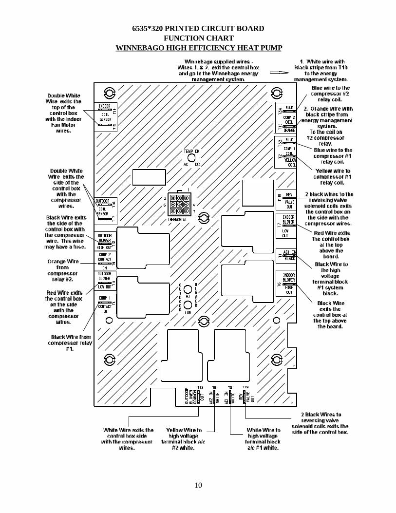
6535*320 PRINTED CIRCUIT BOARDFUNCTION CHART
WINNEBAGO HIGH EFFICIENCY HEAT PUMP

11
IV. 6535*320 PRINTED CIRCUIT BOARDFUNCTION CHART

12
PRINTED CIRCUIT BOARD 9-PIN THERMOSTAT PLUG CONNECTOR
The figure above depicts the 9-pin printed circuit board socket as if you were looking straight at it.
NOTE
1. Pin connections in this p.c. board socket are identical to those in the thermostat.
2. Low voltage connections to the p.c. board socket are subject to thermostattime delays.
3. The “Green Light” (freeze circuit) may be bypassed for troubleshooting purposes by bridging between terminals 1 & 3 (F&FY).

13
PRINTED CIRCUIT BOARD INDOOR BLOWER SECTION
Note: Both High and Low Indoor Blower speeds operate on Circuit #1
HIGH SPEED INDOOR BLOWER OPERATION
1. Begins with a call from the thermostat, 12 volt positive (+) to terminal #7 (GH) in the 9-pin connector. (Black wire at thethermostat). The Ground (-) is Blue in terminal #4.
2. The High Speed relay closes on the board. 115 volts (HOT leg) signal should appear on T6, Indoor Blower High Out terminal. The 115 volt Neutral leg to the motor is not routed through the printed circuit board.
3. The 115 volts (HOT leg) power continues from terminal T6 to the High Speed motor tap.
4. The motor starts and runs on High Speed until the signal is lost from the thermostat.
LOW SPEED INDOOR BLOWER OPERATION
1. Begins with a call from the thermostat, 12 volt positive (+) to terminal #9 (GL) in the 9-pin connector. (Purple wire at thethermostat). The Ground (-) is Blue in terminal #4.
2. The Low Speed relay closes on the board. 115 volts (HOT leg) signal should appear on T7, Indoor Blower Low Out terminal. The 115 volt Neutral leg to the motor is not routed through the printed circuit board.
3. The 115 volts (HOT leg) power continues from terminal T7 to the Low Speed motor tap.
4. The motor starts and runs on Low Speed until the signal is lost from the thermostat.
14
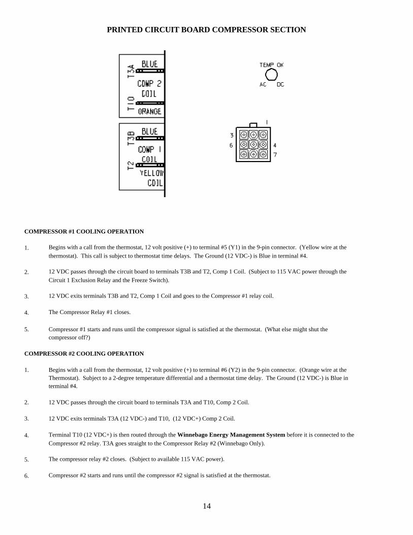
PRINTED CIRCUIT BOARD COMPRESSOR SECTION
COMPRESSOR #1 COOLING OPERATION
1. Begins with a call from the thermostat, 12 volt positive (+) to terminal #5 (Y1) in the 9-pin connector. (Yellow wire at thethermostat). This call is subject to thermostat time delays. The Ground (12 VDC-) is Blue in terminal #4.
2. 12 VDC passes through the circuit board to terminals T3B and T2, Comp 1 Coil. (Subject to 115 VAC power through theCircuit 1 Exclusion Relay and the Freeze Switch).
3. 12 VDC exits terminals T3B and T2, Comp 1 Coil and goes to the Compressor #1 relay coil.
4. The Compressor Relay #1 closes.
5. Compressor #1 starts and runs until the compressor signal is satisfied at the thermostat. (What else might shut thecompressor off?)
COMPRESSOR #2 COOLING OPERATION
1. Begins with a call from the thermostat, 12 volt positive (+) to terminal #6 (Y2) in the 9-pin connector. (Orange wire at theThermostat). Subject to a 2-degree temperature differential and a thermostat time delay. The Ground (12 VDC-) is Blue interminal #4.
2. 12 VDC passes through the circuit board to terminals T3A and T10, Comp 2 Coil.
3. 12 VDC exits terminals T3A (12 VDC-) and T10, (12 VDC+) Comp 2 Coil.
4. Terminal T10 (12 VDC+) is then routed through the Winnebago Energy Management System before it is connected to theCompressor #2 relay. T3A goes straight to the Compressor Relay #2 (Winnebago Only).
5. The compressor relay #2 closes. (Subject to available 115 VAC power).
6. Compressor #2 starts and runs until the compressor #2 signal is satisfied at the thermostat.
15
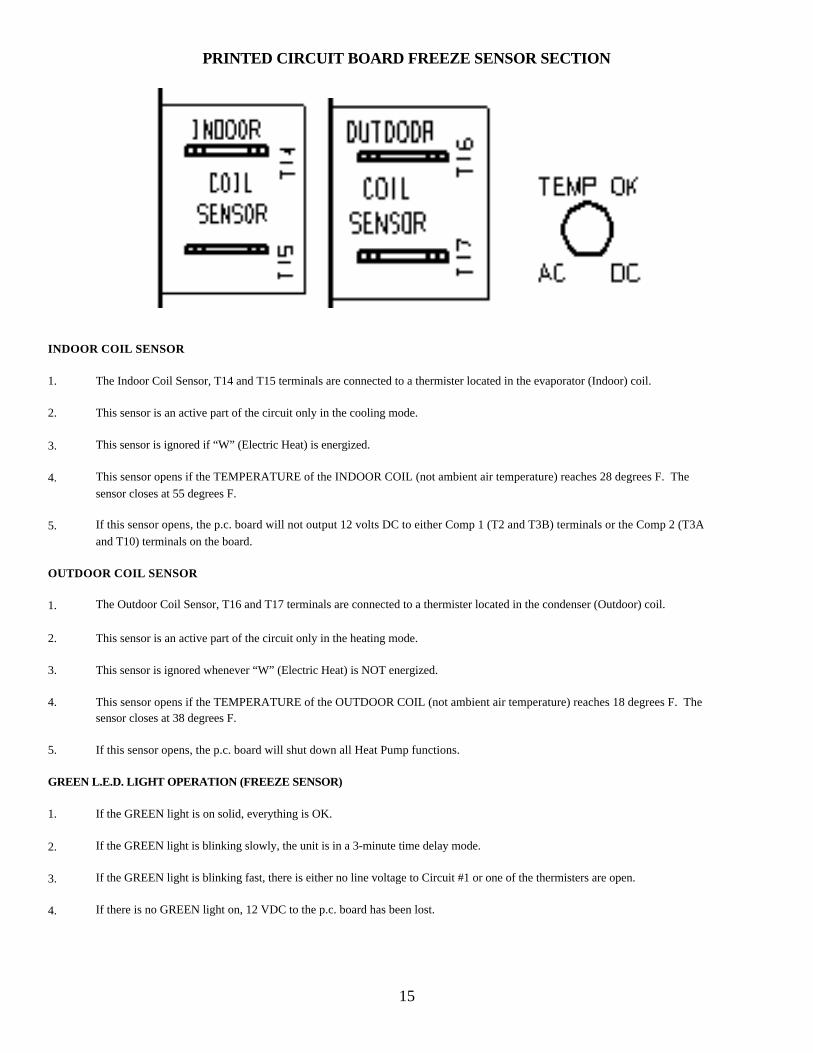
PRINTED CIRCUIT BOARD FREEZE SENSOR SECTION
INDOOR COIL SENSOR
1. The Indoor Coil Sensor, T14 and T15 terminals are connected to a thermister located in the evaporator (Indoor) coil.
2. This sensor is an active part of the circuit only in the cooling mode.
3. This sensor is ignored if “W” (Electric Heat) is energized.
4. This sensor opens if the TEMPERATURE of the INDOOR COIL (not ambient air temperature) reaches 28 degrees F. Thesensor closes at 55 degrees F.
5. If this sensor opens, the p.c. board will not output 12 volts DC to either Comp 1 (T2 and T3B) terminals or the Comp 2 (T3Aand T10) terminals on the board.
OUTDOOR COIL SENSOR
1. The Outdoor Coil Sensor, T16 and T17 terminals are connected to a thermister located in the condenser (Outdoor) coil.
2. This sensor is an active part of the circuit only in the heating mode.
3. This sensor is ignored whenever “W” (Electric Heat) is NOT energized.
4. This sensor opens if the TEMPERATURE of the OUTDOOR COIL (not ambient air temperature) reaches 18 degrees F. Thesensor closes at 38 degrees F.
5. If this sensor opens, the p.c. board will shut down all Heat Pump functions.
GREEN L.E.D. LIGHT OPERATION (FREEZE SENSOR)
1. If the GREEN light is on solid, everything is OK.
2. If the GREEN light is blinking slowly, the unit is in a 3-minute time delay mode.
3. If the GREEN light is blinking fast, there is either no line voltage to Circuit #1 or one of the thermisters are open.
4. If there is no GREEN light on, 12 VDC to the p.c. board has been lost.

16
PRINTED CIRCUIT BOARD OUTDOOR BLOWER SECTION
Note: These two sections of the p.c. board control both 115 volt (HOT and NEUTRAL) power legs to the OUTDOOR BLOWER.
LOW SPEED OUTDOOR BLOWER OPERATION
1. Begins with a 115 volt (HOT leg) signal received from the #1 Compressor Relay to the Comp 1 Contact In, T4 terminal on thep.c. board.
2. After a 2-second delay, 115 volts (HOT leg) signal should appear at the T11, Outdoor Blower Low Out terminal on the p.c.board. The 115 volt (NEUTRAL) leg is also completed to terminal T13, Outdoor Blower Common after the same 2-second timedelay.
3. The Outdoor Blower starts and runs on Low speed until compressor #1 goes off or the second stage cooling is energized.
HIGH SPEED OUTDOOR BLOWER OPERATION
1. Begins with a 115 volt (HOT leg) signal received from the #2 Compressor Relay to the Comp 2 Contact In, T9 on the p.c.board.
2. Immediately the relays will open the circuits to T11, Outdoor Blower Low Out and T13, Outdoor Blower Common.
3. After a 2-second delay, 115 volts (HOT leg) signal should appear at the T12, Outdoor Blower High Out terminal on the p.c.board. Power is also re-applied to the 115 volt (NEUTRAL) leg, terminal T13, Outdoor Blower Common after the same 2-second time delay.
4. The Outdoor Blower starts and runs on High speed until compressor #2 goes off.
17
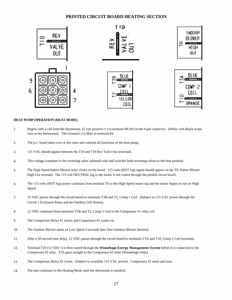
PRINTED CIRCUIT BOARD HEATING SECTION
.
HEAT PUMP OPERATION (HEAT MODE)
1. Begins with a call from the thermostat, 12 volt positive (+) to terminal #8 (W) in the 9-pin connector. (White with Black stripewire at the thermostat). The Ground (-) is Blue in terminal #4.
2. The p.c. board takes over at this time and controls all functions of the heat pump.
3. 115 VAC should appear between the T18 and T19 Rev Valve Out terminals.
4. This voltage continues to the reversing valve solenoid coils and switches both reversing valves to the heat position.
5. The High Speed Indoor Blower relay closes on the board. 115 volts (HOT leg) signal should appear on the T6, Indoor BlowerHigh Out terminal. The 115 volt NEUTRAL leg to the motor is not routed through the printed circuit board.
6. The 115 volts (HOT leg) power continues from terminal T6 to the High Speed motor tap and the motor begins to run on HighSpeed.
7. 12 VDC passes through the circuit board to terminals T3B and T2, Comp 1 Coil. (Subject to 115 VAC power through theCircuit 1 Exclusion Relay and the Outdoor Coil Sensor).
8. 12 VDC continues from terminals T3B and T2, Comp 1 Coil to the Compressor #1 relay coil.
9. The Compressor Relay #1 closes and Compressor #1 comes on.
10. The Outdoor Blower starts on Low Speed 2-seconds later (See Outdoor Blower Section).
11. After a 30-second time delay, 12 VDC passes through the circuit board to terminals T3A and T10, Comp 2 Coil terminals.
12. Terminal T10 (12 VDC+) is then routed through the Winnebago Energy Management System before it is connected to theCompressor #2 relay. T3A goes straight to the Compressor #2 relay (Winnebago Only).
13. The Compressor Relay #2 closes. (Subject to available 115 VAC power). Compressor #2 starts and runs.
14. The unit continues in the Heating Mode until the thermostat is satisfied.
18
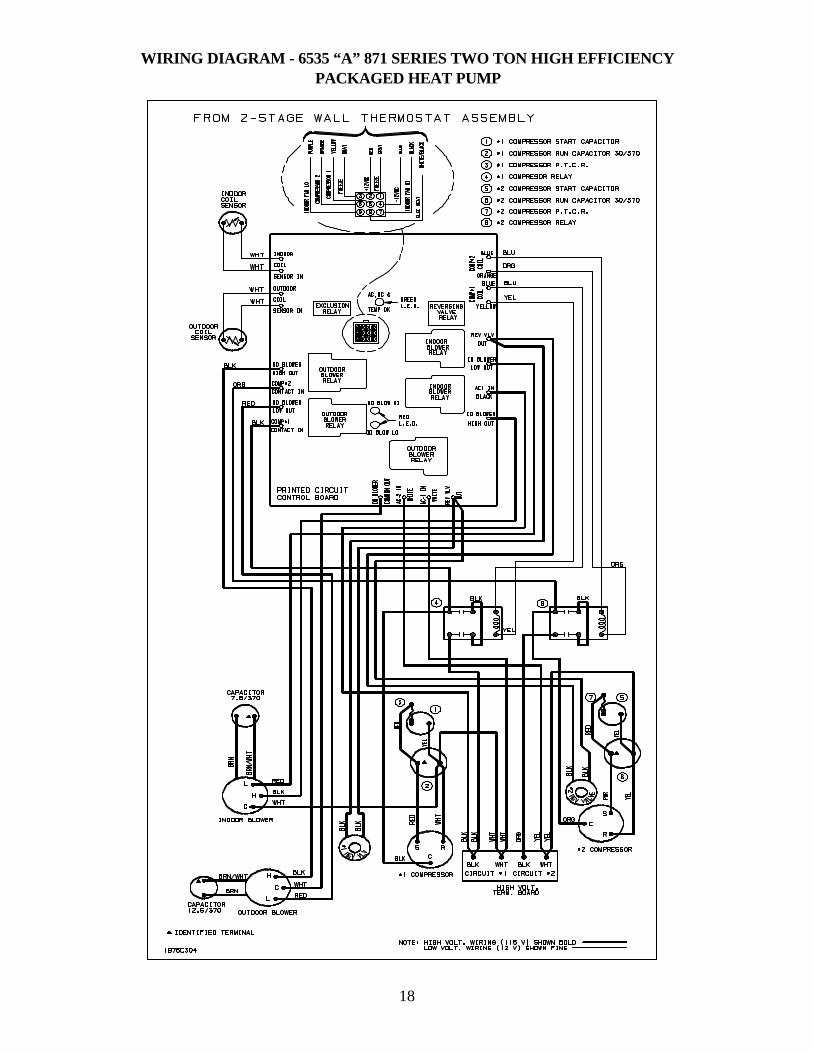
WIRING DIAGRAM - 6535 “A” 871 SERIES TWO TON HIGH EFFICIENCYPACKAGED HEAT PUMP

19
WIRING DIAGRAM FOR 6535-671, 6535A671, 6535B871, 6537 & 6538 SERIESTWO TON HIGH EFFICIENCY PACKAGED HEAT PUMP