modelling and optimisation of a multiaxial fabric and optimisation of a multiaxial fabric thomas...
TRANSCRIPT
Modelling and Optimisation of a Multiaxial Fabric
Thomas James
13th SPE-ACCE
September 2013

Our goal
The role of the converter
Optimisation of multiaxial fabrics through physical testing
Capabilities of PAMFORM simulation
Modelling a Multiaxial
Simulating forming processes
Extraction of useful results
Case Studies
Effects of Stitch Direction
Optimisation of Shear Modulus
Next steps
Slide 2
Outline

Our goal
The role of the converter
Optimisation of multiaxial fabrics through physical testing
Capabilities of PAMFORM simulation
Modelling a Multiaxial
Simulating forming processes
Extraction of useful results
Case Studies
Effects of Stitch Direction
Optimisation of Shear Modulus
Next steps
Slide 3
Outline

Slide 4
Our goal

Composite engineers..
Calculate design loads
Use knowledge of fibre properties
Use knowledge of composite properties
Specify a fibre and resin type
Specify a fabric weight
Specify a number of layers
Slide 5
Our goal

Slide 6
Composite engineers..
Calculate design loads
Use knowledge of fibre properties
Use knowledge of composite properties
Specify a fibre and resin type
Specify a fabric weight
Specify a number of layers
Composite builders..
Select fabric type/construction
Work around process problems
Our goal

Slide 7
Composite engineers..
Calculate design loads
Use knowledge of fibre properties
Use knowledge of composite properties
Specify a fibre and resin type
Specify a fabric weight
Specify a number of layers
Composite builders..
Select fabric type/construction
Work around process problems
Our goal

Slide 8
Composite engineers..
Calculate design loads
Use knowledge of fibre properties
Use knowledge of composite properties
Specify a fibre and resin type
Specify a fabric weight & construction
Specify a number of layers
Composite builders..
Help to Select fabric type/construction
Work around process problems
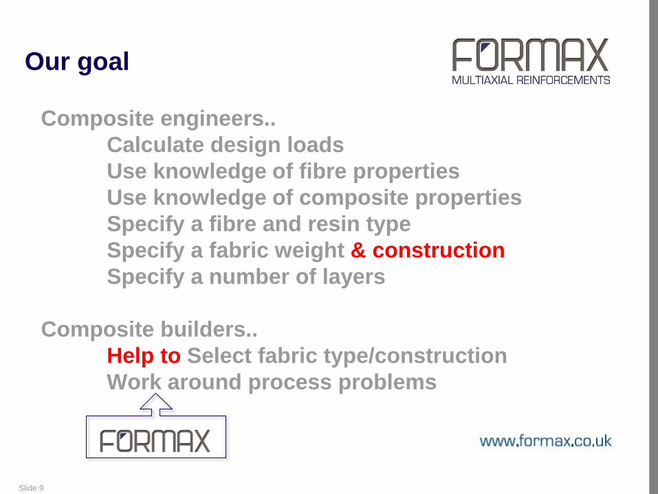
Our goal
Slide 9
Composite engineers..
Calculate design loads
Use knowledge of fibre properties
Use knowledge of composite properties
Specify a fibre and resin type
Specify a fabric weight & construction
Specify a number of layers
Composite builders..
Help to Select fabric type/construction
Work around process problems
Our goal

Slide 10
About FORMAX
Producer of multiaxial and woven reinforcements for composites
Founded 1998
Independently owned
Located in Leicestershire, UK
128 full time employees
14 lines producing over 8000 tons of glass fabrics, 700 tons of carbon, plus
other fabrics using aramid, natural and thermoplastic fibres.
Turnover 2012: £23.5m

Our goal
The role of the converter
Optimisation of multiaxial fabrics through physical testing
Capabilities of PAMFORM simulation
Modelling a Multiaxial
Simulating forming processes
Extraction of useful results
Case Studies
Effects of Stitch Direction
Optimisation of Shear Modulus
Next steps
Slide 11
Outline

Slide 12
The role of the converter
PRE- PROCESSING:
FIBRES SIZING
Group fibres
POST- PROCESSING: COMPOSITES
MANUFACTURE
Slide 13
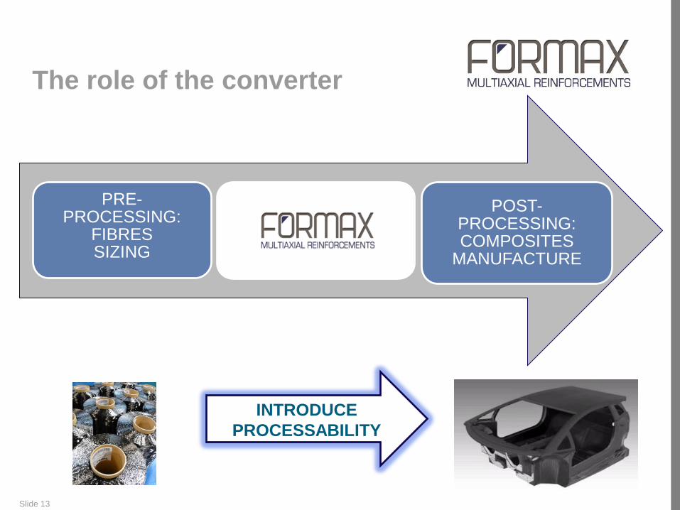
The role of the converter
INTRODUCE
PROCESSABILITY
PRE- PROCESSING:
FIBRES SIZING
Group fibres
POST- PROCESSING: COMPOSITES
MANUFACTURE

Slide 14
The role of the converter
INTRODUCE
PROCESSABILITY
Group 100’s of tows to allow economic production…

Slide 15
The role of the converter
INTRODUCE
PROCESSABILITY
Group 100’s of tows to allow economic production…
..and introduce a fabric structure…

Slide 16
The role of the converter
INTRODUCE
PROCESSABILITY
Group 100’s of tows to allow economic production…
..and introduce a fabric structure…
The structure allows us to…
.
.
.

Slide 17
The role of the converter
INTRODUCE
PROCESSABILITY
Group 100’s of tows to allow economic production…
..and introduce a fabric structure…
The structure allows us to…
Control fabric stability
.
.

Slide 18
The role of the converter
INTRODUCE
PROCESSABILITY
Group 100’s of tows to allow economic production…
..and introduce a fabric structure…
The structure allows us to…
Control fabric stability
Control fabric drape
.
Slide 19
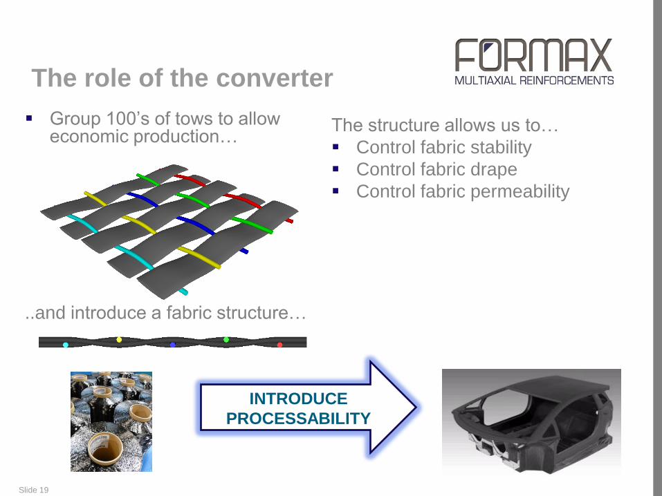
The role of the converter
INTRODUCE
PROCESSABILITY
The structure allows us to…
Control fabric stability
Control fabric drape
Control fabric permeability
Group 100’s of tows to allow economic production…
..and introduce a fabric structure…

Slide 20
The role of the converter
FIBRE PROPERTIES
Group fibres COMPOSITE PROPERTIES
MAXIMISE
PERFORMANCE

Slide 21
FORMAX R&D Laboratory
Established January 2011
Employs 2 people and 2 interns
Processability testing of fabrics
Production & inspection of composite panels
Test composite performance: mechanical testing
Optimisation of fabric design and production
Optimisation of process from fibre to finished component
Process simulation using PAMFORM

Slide 22
Customers
Key Markets are Marine, Automotive, Sports, Wind Energy, Oil and Gas.

Our goal
The role of the converter
Optimisation of multiaxial fabrics through physical testing
Capabilities of PAMFORM simulation
Modelling a Multiaxial
Simulating forming processes
Extraction of useful results
Case Studies
Effects of Stitch Direction
Optimisation of Shear Modulus
Next steps
Slide 23
Outline
Slide 24
How are these fabric structures selected?
Fabric Selection Process

Slide 25
How are these fabric structures selected?
Fabric Selection Process
feedback during production run
Slide 26
How are these fabric structures selected?
feedback during production run
physical testing and optimisation during the design stage
Fabric Selection Process

Physical Testing
Aim: To quantify the effect of variation of fabric constructions on
processability and performance for a specific component
27 fabrics tested, all with same fibre type, weight and
orientation
Processability tests conducted:
Cutting, Drape, Stability, Retain & Permeability

Slide 28
Physical Testing

Slide 29
Physical Testing
Slide 30
How are these fabric structures selected?
Feedback during production run
Physical testing and optimisation during the design stage
Fabric Selection Process

Slide 31
How are these fabric structures selected?
Feedback during production run
Physical testing and optimisation during the design stage
Simulation and optimisation during the design stage
Fabric Selection Process

Our goal
The role of the converter
Optimisation of multiaxial fabrics through physical testing
Capabilities of PAMFORM simulation
Modelling a Multiaxial
Simulating forming processes
Extraction of useful results
Case Studies
Effects of Stitch Direction
Optimisation of Shear Modulus
Next steps
Slide 32
Outline

Collaboration between FORMAX
and ESI
Objectives of the Collaboration
To assess the existing capabilities of PAM-FORM for simulation
of multiaxial fabrics
To assess the ability for PAM-FORM to model the manual
preform process
Primary Challenges
Modelling a Multiaxial
How can the properties of the stitched fabric be modelled?
What are the implications on processing time and results?
Modelling the Manual Forming Process
How can manual operator forces be modelled?
What are the implications on processing time and results?
Prediction of Required Ply Shapes
Can we predict the required developed ply shapes?

Modelling a Multiaxial
Multiaxial fabrics (±45) characterised through material testing
Tensile Test Bias Test Bending Test

Calibrated material model tested using a more complex model
Modelling a Multiaxial

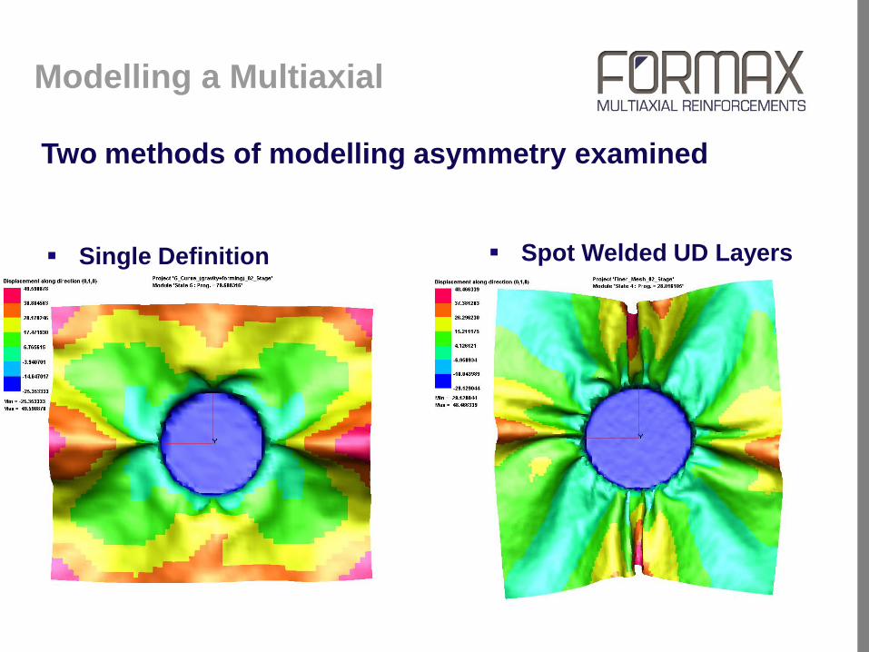
Two methods of modelling asymmetry examined
Spot Welded UD Layers
Two UD plys modelled
Spot weld nodes
spaced to replicate
stitch
Single Definition
Fabric Model
Shear modulus different for
positive and negative shear
angles
Single Definition
Fabric Model
Shear modulus different for
positive and negative shear
angles
Shear modulus can be defined
with respect to the angle
change
Modelling a Multiaxial
Spot Welded UD Layers
Two plys modelled
Spot weld nodes
spaced to replicate
stich
Good approximation of
wrinkle size
Processing time of 40
mins
Single Definition
Fabric Model
Sear modulus different for
positive and negative shear
angles
Modelling a Multiaxial
Two methods of modelling asymmetry examined

Which method is best?
Spot Welded UD Layers
Accuracy of Model
Asymmetry shown in the model
Further refinement needed to
accurately simulate wrinkling
Processing Time Punch Stage – 40 mins
Single Definition
Accuracy of Model
Asymmetry shown in the model
Further calibration is required to
accurately model experiment
Processing Time Punch Stage – 5 mins
Single Definition
Modelling a Multiaxial

Application of operator force is not straight forward
How do we model the movement and pressure that a hand
imparts on the fabric?
Method of application in the model must:
Able to cause the ply to conform around a geometry
Able to highlight any features that occur during forming
Two forming force application methods were found to be
successful:
Applying forces to tools
Diaphragm forming
Simulating Forming Processes

Mould and Punch
Model consists of mould (green) and punch (red)
Simulating Forming Processes
Diaphragm Forming
Diaphragm positioned over ply
and geometry
Vacuum applied to diaphragm to
pull the ply onto the geometry
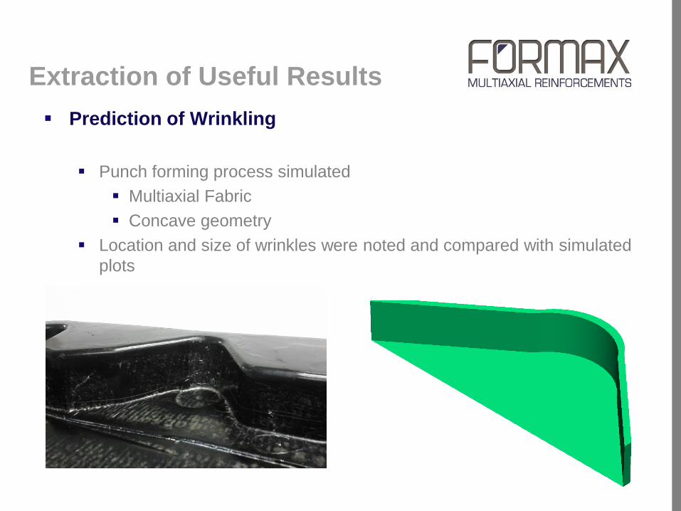
Extraction of Useful Results
Prediction of Wrinkling
Punch forming process simulated
Multiaxial Fabric
Concave geometry
Location and size of wrinkles were noted and compared with simulated
plots
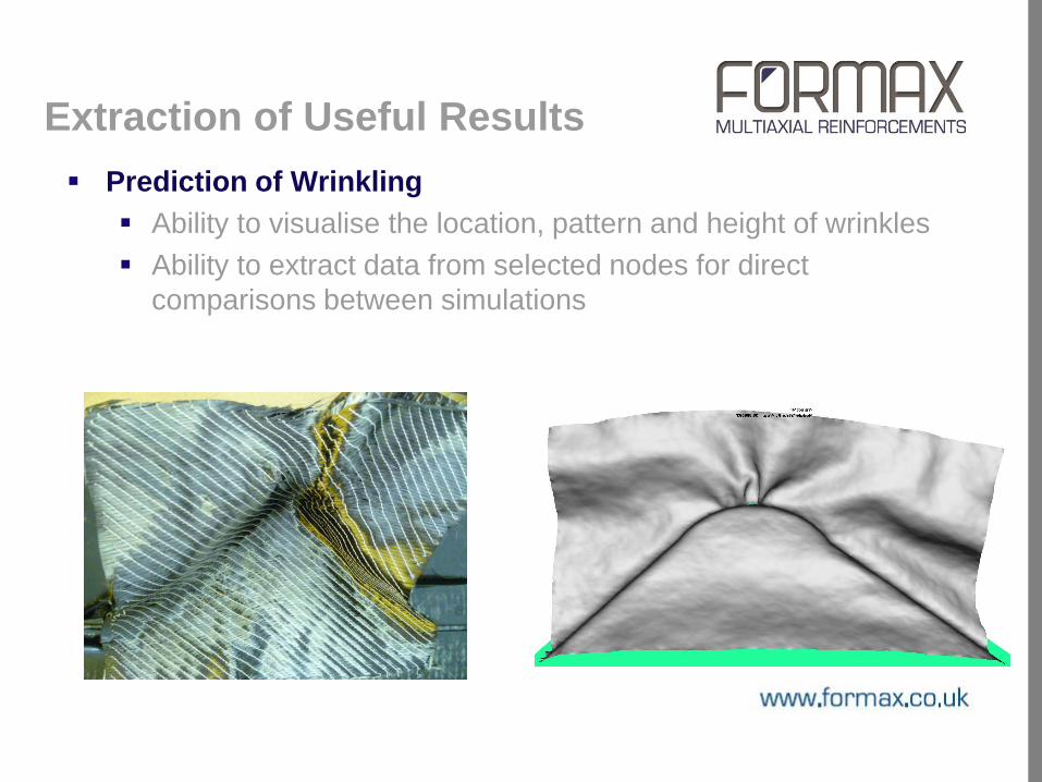
Extraction of Useful Results
Prediction of Wrinkling
Ability to visualise the location, pattern and height of wrinkles
Ability to extract data from selected nodes for direct
comparisons between simulations

Prediction of Laddering
Occurs when fabric is
strained normal to the stitch
direction
Onset of laddering occurs at
a given strain
Predicted by comparing
model strain to experimental
laddering strain
Extraction of Useful Results

Leading edge
Trailing edge
There is a directionality to the laddering
properties of the multiaxial
Leading edge – does not ladder
Trailing edge – ladders at a given strain
Multiaxial model did not discriminate between
leading and trailing edge
Prediction of Laddering
Extraction of Useful Results

Modelled laddering strain
Taken from edges of
Multiaxial ply model
Element strain plotted with
respect to a defined
direction which is
orientated across the stitch
in a local region of the
deformed blank
Extraction of Useful Results

Generation of Developed Shapes

Simulation Capabilities: Summary
Modelling a multiaxial
Single definition is our preferred method of modelling the multiaxial
Asymmetric properties can be obtained through assigning different
values of shear modulus for positive and negative shear angles
Modelling manual forming processes
Investigation into the methods of modelling manual forming techniques
Diaphragm and rigid tools used in successful forming simulations
Extraction of useful results
Wrinkle patterns have been predicted by the model
Prediction of laddering possible by further examination of the laddering
strains

Our goal
The role of the converter
Optimisation of multiaxial fabrics through physical testing
Capabilities of PAMFORM simulation
Modelling a Multiaxial
Simulating forming processes
Extraction of useful results
Case Studies
Effects of Stitch Direction
Optimisation of Shear Modulus
Next steps
Slide 49
Outline

Case Study: Effects of Stitch Direction
Examined the effects of the stitch orientation in a real automotive
component
Fibre orientation remained the same relative to the component
Fabric models were modified to account for a changing stitch direction

Case Study: Stitch Orientation
The stitch influences the shear behaviour of the fabric
Stitch orientation can be altered without changing fibre orientation of the
fibres
Simulation was used to examine the most appropriate stitch orientation

Case Study: Stitch Orientation
PAMFORM simulation
indicated that wrinkles would
not form when the stitch was
orientated at either 90º or 45º
to the part.

Our goal
The role of the converter
Optimisation of multiaxial fabrics through physical testing
Capabilities of PAMFORM simulation
Modelling a Multiaxial
Simulating forming processes
Extraction of useful results
Case Studies
Effects of Stitch Direction
Optimisation of Shear Modulus
Next steps
Slide 53
Outline
Introduction to Optimisation
Without simulation
Prior optimisation carried out physically
Required fabrics to be manufactured
Required a physical model of the geometry
With simulation
Fabric optimisation carried out before geometry has been finalised
Can determine the required fabric properties required before the
material is specified

How can simulation be used to
Optimise a Fabric
Idealised optimisation
Looks for the existence of a
minimum for a given variable
when a material parameters
are changed
Optimisation through simulation
requires
Large numbers of input files
Incrementally changing
material properties
Automation throughout the
process
Fabric Shear Modulus
Initial Optimisation
Refined Optimisation
No
de
dis
tan
ce
fro
m m
ou
ld

What needs to be optimised?
A trade off exists between wrinkles and stability with regard to the shear modulus of the fabric
G.Cosϴ
Wri
nkle
s/S
tab
ilit
y
LOW G HIGH G

For THIS case desirable fabric will:
Not wrinkle when forced into the mould
Be as stable as possible
Therefore the optimum fabric will be a trade off between the two factors i.e.
The maximum shear modulus that will provide a wrinkle free
formed component
Where is the Optimum Fabric
Modulus?

Step One: Initial Optimisation
G.Cosϴ = 0.0001 G.Cosϴ =0.001
220
221
222
223
224
225
226
227
228
229
230
231
0.000001 1.00E-05 0.0001 0.001 0.01 0.1
G.Cos(theta)
So
me o
f N
od
e Z
po
sit
ion

Step One: Initial Optimisation
G.Cosϴ = 0.0001 G.Cosϴ =0.001
220
221
222
223
224
225
226
227
228
229
230
231
0.000001 1.00E-05 0.0001 0.001 0.01 0.1
G.Cos(theta)
So
me o
f N
od
e Z
po
sit
ion

Step One: Initial Optimisation
G.Cosϴ = 0.0001 G.Cosϴ =0.001
220
221
222
223
224
225
226
227
228
229
230
231
0.000001 1.00E-05 0.0001 0.001 0.01 0.1
G.Cos(theta)
So
me o
f N
od
e Z
po
sit
ion

221
222
223
224
225
226
227
228
229
230
0.0001 0.0002 0.0003 0.0004 0.0005 0.0006 0.0007 0.0008 0.0009 0.001
G.Cos(Theta)
Su
m o
f N
od
e Z
Po
sit
ion
s
Step Two: Refined Optimisation
G.Cosϴ = 0.0001 G.Cosϴ =0.001

221
222
223
224
225
226
227
228
229
230
0.0001 0.0002 0.0003 0.0004 0.0005 0.0006 0.0007 0.0008 0.0009 0.001
G.Cos(Theta)
Su
m o
f N
od
e Z
Po
sit
ion
sStep Two: Refined Optimisation
Initial optimisation suggests a desired G.Cosϴ value of 0.0001
Further analysis suggests the maximum G.Cosϴ value of 0.0003
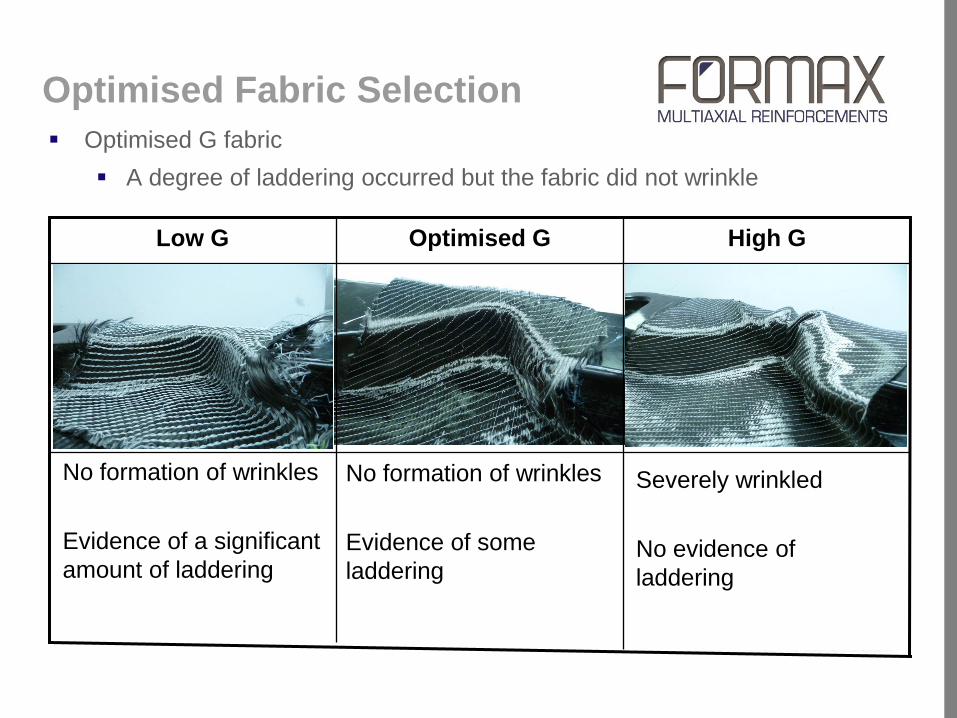
Optimised Fabric Selection
Optimised G fabric
A degree of laddering occurred but the fabric did not wrinkle
No formation of wrinkles
Evidence of some
laddering
High G Optimised G Low G
No formation of wrinkles
Evidence of a significant
amount of laddering
Severely wrinkled
No evidence of
laddering

Optimisation Conclusions
Simulation has been used to examine the trade offs in processability when changing a given material parameter
Large numbers of simulations with incremental changes in can be created automatically
This can be applied to several areas of process analysis
Examination of material properties
Examination of process parameters
Examination of geometry
Theoretical optimum has been calculated
Our goal
The role of the converter
Optimisation of multiaxial fabrics through physical testing
Capabilities of PAMFORM simulation
Modelling a Multiaxial
Simulating forming processes
Extraction of useful results
Case Studies
Effects of Stitch Direction
Optimisation of Shear Modulus
Next steps
Slide 66
Outline

Next Steps
A UK Government funded Knowledge Transfer Partnership with
Nottingham University to begin in April 2013, will develop:
A database of all processability and performance parameters for multiaxial
fabrics
A comprehensive understanding of the effects of processability
characteristics on composite performance
Develop capabilities for producing the developed shape of preforms

Thank You