modeling the effects of soil-structure interaction on a...
TRANSCRIPT
CIVIL ENGINEERING PRACTICE FALL/WINTER 2005 51
LEWIS EDGERS, MASOUD SANAYEI & JOSEPH L. ALONGE
The interaction of a building, its founda-tion and the underlying soils may haveimportant effects on the behavior of
each of these components as well as on theoverall system behavior. For example, the rel-ative stiffness of a building structure, its matfoundation and the soils that support thefoundation will influence the stresses and dis-placements of both the structure and soil.Soil-structure interaction (SSI) effects aresometimes neglected by the use of a structur-al model supported on a fixed base. Other
simple models assume an ideally flexible orinfinitely rigid foundation on an elastic sub-soil.
An investigation of the effects of SSI on thestresses and displacements in the structureand the soil of a model fifty-story steel framestructure with a concrete mat foundationbearing on a deformable soil was undertakenas a means of best understanding how to per-form and apply SSI analyses. The studyincluded investigating the effects of the stiff-nesses of the building, its mat foundation andan elastic subsoil on the stresses, internalforces and displacements of the building,foundation and subsoils. The soil-structuremodel also considered the effects of founda-tion embedment.
Development of Computer ModelsThe study of SSI was conducted with a build-ing frame model developed within the contextof research on the effects of increased wind
Design Considerations
Modeling the Effects ofSoil-Structure Interactionon a Tall BuildingBearing on a MatFoundation
Examining soil-structure interaction can result in more efficient structural designs.

loads due to global climate change on tallbuildings in Boston.1 The building model isrepresentative of many taller buildings foundin large cities.
For the initial analyses, an ANSYS model ofthe building frame was pin-connected to arigid base (see Figure 1). The two-dimension-al building model — 182.9 meters (600 feet)high by 30.5 meters (100 feet) wide by 0.3meters (1 foot) — consists of 255 nodes and550 elements. The framing system is based ona steel member with core bracing similar tothat of a Pratt brace. The floor height is 3.66meters (12 feet) and is typical of many tallbuildings.2 It uses the Beam3 as frame ele-ments and Link1 as truss elements. The fram-ing material is assumed to be steel and theflooring system is assumed to be metal deck-ing with a concrete slab 10.2 centimeters (4inches) thick. The wind loads were applied aspoint loads along the left side of the structure,and the vertical dead and live loads wereapplied together as uniform loads to the hori-zontal members. Gravity loads actuate theself-weight of the structure. The connectionbetween the building and mat foundation wasmodeled by a pin connection at the base of thecolumns. Figure 2 shows a close-up of thebuilding frame, lateral load carrying systemand the pin connections to a rigid support.The structure is fixed at the base in order toexamine its response (since the structure isordinarily analyzed by ignoring the SSI).
Figure 3 shows the finite-element model ofthe building frame supported by a mat foun-dation bearing on a stiff linear elastic soil. Thismodel was developed in order to simulaterealistic foundation design conditions. Thesoil mass was represented by a mesh 213meters (700 feet) wide by 152 meters (500 feet)deep, consisting of forty-two quadrilateralplane strain elements. A set of elements andnodes are added to the top of the soil mass torepresent the concrete mat. The coincidentnodes at the soil-concrete interface weremerged so that there is full continuity with noslippage at this interface along the base of thefoundation.
A two-dimensional, rather than three-dimensional, structural model was developedin order to increase computational efficiency.In order to represent a three-dimensionalstructure in two dimensions, the element stiff-ness and loadings were distributed over a unittwo-dimensional slice of frame bents spaced
52 CIVIL ENGINEERING PRACTICE FALL/WINTER 2005
FIGURE 1. ANSYS model of the fifty-storybuilding pin-supported on a rigid base.

at 7.6 meters (25 feet). The bending rigidity, EI,and the axial rigidity, EA, of the building’sbeams and columns, located at the 7.6-meter(25-foot) bay spacing, were scaled by reducingthe common elastic modulus parameter, E, byone-twenty-fifth. Thus, it was unnecessary toadjust the moment of inertia, I, or cross-sec-tional area, A, of each member. The materialdensity for the discrete members was scaledby one-twenty-fifth so that full self-weightwas evenly applied over each bay. No scalingwas applied to the properties of the concretemat foundation and the subsoil because theywere continuous. Table 1 summarizes thematerial properties used for these analyses. Atwo-dimensional model would not be applica-ble for situations without symmetry in thethird dimension. For these situations, fullthree-dimensional analyses can be performedwith finite-element packages (such as ANSYSand PLAXIS 3D Foundation).
The dead, live and wind loads used in thisanalysis are based on the Massachusetts StateBuilding Code.3 Seismic loads are not consid-ered. Dead load includes the weight of theframing, flooring, ceiling and mechanical, andpartition load (assumed to be office space).The live load was assumed to be an average ofthe typical loads found in offices, office lob-
bies and corridors. The wind loads are basedon Zone 3 for the Boston metropolitan area,and exposure B for towns and cities. Allapplied dead and live loads were transformedto represent the forces acting on a unit slice ofthe building model. To do so requires a one-twenty-fifth scaling of the weight of all steelelements spaced at 7.6 meters (25 feet) but noadjustment of distributed loads. The windloads were concentrated at each of the build-ing’s floor levels. Tables 2 and 3 summarizethe loads applied to the unit slice model.
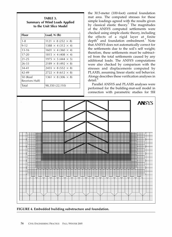
Figure 4 shows the details of the finite-ele-ment model, modified to describe an embed-ded foundation. The computer model of theexcavated areas includes both soil elementsand elements representing foundation walls,mat foundation and two stories of an under-ground garage structure. The linear elasticmodel requires full continuity between the soiland the concrete walls and mat. The embeddedmodel also includes two levels of columns andconcrete beams to represent the undergroundpart of the structure. The entire mesh includes7,083 nodes and 6,948 elements. For the pur-pose of these linear-elastic analyses, excavationsupport issues have been neglected.
The ANSYS analyses for staged excavationand construction were performed as follows:
CIVIL ENGINEERING PRACTICE FALL/WINTER 2005 53
FIGURE 2. The lower floors of a fifty-story building pin-supported on a rigid base.

Initial Step. Generate initial stresses in thesoil (mat and building elements deactivated[see Figure 3]).
Step 1. Change material properties forthe right foundation wall (soil to concrete[see Figure 4]).
Step 2. Change material properties forthe left foundation wall (soil to concrete[see Figure 4]).
Step 3. Deactivate elements representingthe excavated soil from between the walls(see Figure 4).
54 CIVIL ENGINEERING PRACTICE FALL/WINTER 2005
FIGURE 3. An ANSYS model of a fifty-story building supported on a mat foundation andsoil.

Step 4. Activate mat elements and changematerial to concrete (see Figure 4).
Step 5. Activate the fifty-story frame (seeFigure 3); apply dead and live loads (seeTable 2).
Step 6. Apply wind (see Table 3) loads tothe fifty-story frame.
(The sign conventions for the results presentedhere are that downward displacements [settle-ments] and compressive stresses are negative.)
Linear Elastic Analyses
Verification Analyses. An initial series ofANSYS runs were performed using the soilmesh of Figure 3, without the building frame,in order to verify the operation of the pro-gram, including mesh generation and the cal-culation of initial geostatic stresses.4 Loadingconditions included uniform one-dimensionalvertical loading across the entire top boundaryas well as uniform vertical loading applied to
CIVIL ENGINEERING PRACTICE FALL/WINTER 2005 55
TABLE 2.Summary of Dead & Live Loads (N/.3m) Applied to the Unit Slice Model
TABLE 1.Material Properties
Material Property Full Value Scaled by 1/25
Steel � 77 kN/m3 (490 pcf) 3.1 kN/m3 (19.6 pcf)
� 0.30 —
E 199,946,880 kPa(4,176,000 ksf)
7,997,875 kPa(167,040 ksf)
Soil � 20.4 kN/m3 (130 pcf) —
� 0.25 —
E 957,600 kPa(10,000 ksf)
—
Ko 0.40 —
ConcreteFoundation
� 23.6 kN/m3 (150 pcf) —
� 0.15 —
E 27,770,400 kPa(580,000 ksf)
—
Dead Loads, N/.3m (plf) Live Loads, N/.3m (plf)
Floor 220 (50) Offices 222 (50)
Ceiling/Mechanical 44.5 (10) Lobbies 444 (100)
Partition 89 (20) Corridors 356 (80)
Steel 71 (16) Average 342.5 (77)
Total Applied 427 (96) Total Applied 342.5 (77)
Total Dead & Live Load Applied = 427 + 342.5 = 770 N/.3m (173 plf)
the 30.5-meter (100-foot) central foundationmat area. The computed stresses for these simple loadings agreed with the results givenby classical elastic theory.5 The magnitudes of the ANSYS computed settlements werechecked using simple elastic theory, includingthe effects of a rigid layer at finite depth6 and foundation embedment.7 Notethat ANSYS does not automatically correct forthe settlements due to the soil’s self weight;therefore, these settlements must be subtract-ed from the total settlements caused by anyadditional loads. The ANSYS computationswere also checked by comparison with thestresses and displacements computed byPLAXIS, assuming linear elastic soil behavior.Alonge describes these verification analyses indetail.4
Parallel ANSYS and PLAXIS analyses wereperformed for the building-mat-soil model inconnection with parametric studies for SSI
56 CIVIL ENGINEERING PRACTICE FALL/WINTER 2005
FIGURE 4. Embedded building substructure and foundation.
TABLE 3.Summary of Wind Loads Applied
to the Unit Slice Model
Floor Load, N (lb)
1-8 1121 � 8 (252 � 8)
9-12 1388 � 4 (312 � 4)
13-16 1601 � 4 (360 � 4)
17-20 1815 � 4 (408 � 4)
21-25 1975 � 5 (444 � 5)
26-33 2189 � 8 (492 � 8)
34-41 2455 � 8 (552 � 8)
42-49 2722 � 8 (612 � 8)
50 (Roof Receives Half)
1361 � 8 (306 � 8)
Total 98,350 (22,110)
(described later). Because PLAXIS cannotmodel the structure in detail, the column loadswere first computed by ANSYS using thebuilding-foundation-soil model. These columnloads were then applied as an input to PLAXISwith a linear elastic soil model. The programscomputed virtually identical stresses and dis-placements in the soil and concrete mat, whichverified that the building reactions at the matfrom the ANSYS model could be used in thePLAXIS model to find the stresses and defor-mations. This application is permitted due tothe fact that the column reactions from ANSYScapture the load and stress redistributions inthe combined building-mat-soil model.
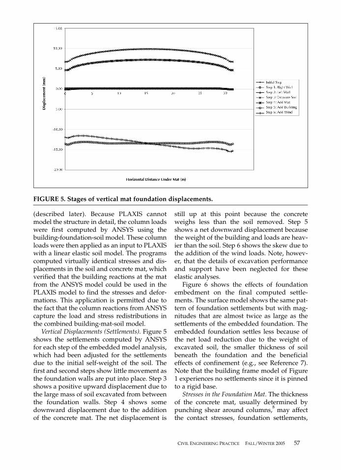
Vertical Displacements (Settlements). Figure 5shows the settlements computed by ANSYSfor each step of the embedded model analysis,which had been adjusted for the settlementsdue to the initial self-weight of the soil. Thefirst and second steps show little movement asthe foundation walls are put into place. Step 3shows a positive upward displacement due tothe large mass of soil excavated from betweenthe foundation walls. Step 4 shows somedownward displacement due to the additionof the concrete mat. The net displacement is
still up at this point because the concreteweighs less than the soil removed. Step 5shows a net downward displacement becausethe weight of the building and loads are heav-ier than the soil. Step 6 shows the skew due tothe addition of the wind loads. Note, howev-er, that the details of excavation performanceand support have been neglected for theseelastic analyses.
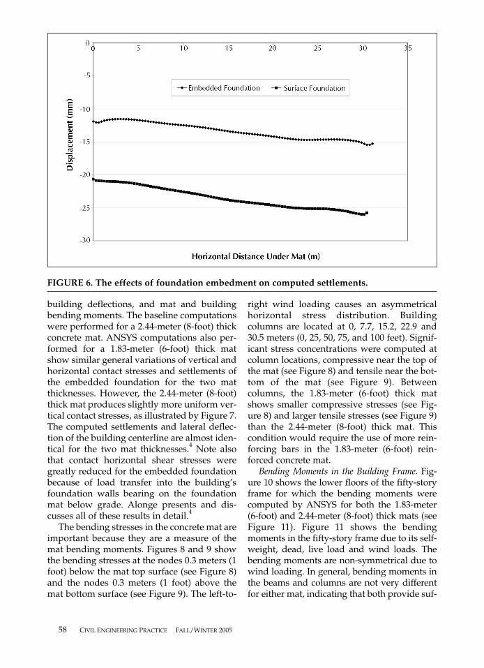
Figure 6 shows the effects of foundationembedment on the final computed settle-ments. The surface model shows the same pat-tern of foundation settlements but with mag-nitudes that are almost twice as large as thesettlements of the embedded foundation. Theembedded foundation settles less because ofthe net load reduction due to the weight ofexcavated soil, the smaller thickness of soilbeneath the foundation and the beneficialeffects of confinement (e.g., see Reference 7).Note that the building frame model of Figure1 experiences no settlements since it is pinnedto a rigid base.
Stresses in the Foundation Mat. The thicknessof the concrete mat, usually determined bypunching shear around columns,8 may affectthe contact stresses, foundation settlements,
CIVIL ENGINEERING PRACTICE FALL/WINTER 2005 57
FIGURE 5. Stages of vertical mat foundation displacements.
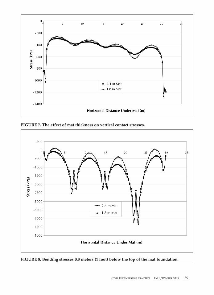
building deflections, and mat and buildingbending moments. The baseline computationswere performed for a 2.44-meter (8-foot) thickconcrete mat. ANSYS computations also per-formed for a 1.83-meter (6-foot) thick matshow similar general variations of vertical andhorizontal contact stresses and settlements ofthe embedded foundation for the two matthicknesses. However, the 2.44-meter (8-foot)thick mat produces slightly more uniform ver-tical contact stresses, as illustrated by Figure 7.The computed settlements and lateral deflec-tion of the building centerline are almost iden-tical for the two mat thicknesses.4 Note alsothat contact horizontal shear stresses weregreatly reduced for the embedded foundationbecause of load transfer into the building’sfoundation walls bearing on the foundationmat below grade. Alonge presents and dis-cusses all of these results in detail.4
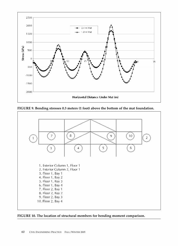
The bending stresses in the concrete mat areimportant because they are a measure of themat bending moments. Figures 8 and 9 showthe bending stresses at the nodes 0.3 meters (1foot) below the mat top surface (see Figure 8)and the nodes 0.3 meters (1 foot) above themat bottom surface (see Figure 9). The left-to-
right wind loading causes an asymmetricalhorizontal stress distribution. Buildingcolumns are located at 0, 7.7, 15.2, 22.9 and30.5 meters (0, 25, 50, 75, and 100 feet). Signif-icant stress concentrations were computed atcolumn locations, compressive near the top ofthe mat (see Figure 8) and tensile near the bot-tom of the mat (see Figure 9). Betweencolumns, the 1.83-meter (6-foot) thick matshows smaller compressive stresses (see Fig-ure 8) and larger tensile stresses (see Figure 9)than the 2.44-meter (8-foot) thick mat. Thiscondition would require the use of more rein-forcing bars in the 1.83-meter (6-foot) rein-forced concrete mat.
Bending Moments in the Building Frame. Fig-ure 10 shows the lower floors of the fifty-storyframe for which the bending moments werecomputed by ANSYS for both the 1.83-meter(6-foot) and 2.44-meter (8-foot) thick mats (seeFigure 11). Figure 11 shows the bendingmoments in the fifty-story frame due to its self-weight, dead, live load and wind loads. Thebending moments are non-symmetrical due towind loading. In general, bending moments inthe beams and columns are not very differentfor either mat, indicating that both provide suf-
58 CIVIL ENGINEERING PRACTICE FALL/WINTER 2005
FIGURE 6. The effects of foundation embedment on computed settlements.
CIVIL ENGINEERING PRACTICE FALL/WINTER 2005 59
FIGURE 7. The effect of mat thickness on vertical contact stresses.
FIGURE 8. Bending stresses 0.3 meters (1 foot) below the top of the mat foundation.
60 CIVIL ENGINEERING PRACTICE FALL/WINTER 2005
FIGURE 9. Bending stresses 0.3 meters (1 foot) above the bottom of the mat foundation.
FIGURE 10. The location of structural members for bending moment comparison.

ficient rigidity to uniformly and effectivelysupport the structure. These two mat thickness-es satisfy the American Concrete Institute (ACI)punching shear requirements.
Figure 11 also shows the results of an analy-sis in which the structure was pinned to arigid foundation, with no deformable soil.These results show variation in the bendingmoments at the leeward exterior column by afactor of 2. These results suggest the impor-tance of modeling the foundation and subsoilswith the structure in order to estimate SSIeffects and the bending moments in the exteri-or columns and beams. However, note that thevariation should be considered within the con-text of the overall column design using theinteraction of axial loads with bendingmoments. Also, there are often other redun-dancies and load redistribution mechanismsin structural systems of tall buildings thatfacilitate the transfer of additional loadsinduced by mat relative deformations.Perhaps more significantly, the model did notdirectly account for construction staging andthe application of loads with time. Effects pre-dicted by the SSI analysis would likely beapplied gradually as the structure was
sequentially built. Therefore, the structurewould have the ability to shift and transferforces and moments more gradually. Evenwith these mitigating factors, however, the SSImodel can lead to significant changes in struc-tural member forces and moments.
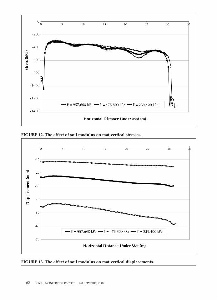
Effects of Soil Modulus. The baseline studieshave been performed with an effective stressYoung’s soil modulus, E, of 957,600 kPa(20,000 ksf) and a 2.33-meter (8-foot) thickmat. In order to investigate the effects of vari-ations of the modulus typical of stiff soils like-ly to be used for the foundation support of tallbuildings, the soil modulus was reduced to239,400 kPa (5,000 ksf) and 478,800 kPa (10,000ksf). Figure 12 shows that, with a reduction insoil modulus, the vertical stress distributionimmediately below the foundation mat (0.3meters [1 foot]) becomes more uniform, withless pronounced stress concentrations beneaththe columns. Overall, the variations in soilvertical stress were insignificant. The horizon-tal stresses and shear contact stresses weresimilarly affected.4
The vertical displacements increase propor-tionally as the soil modulus is decreased (seeFigure 13). Figure 14 shows the increase in
CIVIL ENGINEERING PRACTICE FALL/WINTER 2005 61
FIGURE 11. The effect of mat thickness on structural element bending moments.
62 CIVIL ENGINEERING PRACTICE FALL/WINTER 2005
FIGURE 12. The effect of soil modulus on mat vertical stresses.
FIGURE 13. The effect of soil modulus on mat vertical displacements.

centerline deflection with the decrease in soilmodulus from 957,600 kPa (20,000 ksf) to 239,400 kPa (5,000 ksf). This figure also shows theresults of an analysis in which the structurewas pinned to a rigid base with no deformablesoil. The resulting lateral deflection, dueentirely to the deformability of the structure,underestimates the total lateral deflection thatincludes the SSI effects of the mat foundationand deformable soil.
Figures 15 and 16 show the bending stressdistributions computed in the concrete mat atthe nodes 0.3 meters (1 foot) below the mat topsurface and the nodes 0.3 meters (1 foot) abovethe mat bottom surface, respectively. The com-pressive (negative) and tensile (positive) stressconcentrations appearing at the top and bot-tom of the mat that were noted earlier (seeFigures 9 and 10) are still evident. However,the concentrations become much larger withdecreasing soil modulus, more than doublingfor the range of soil moduli assumed. Figures15 and 16 resemble mat bending moment dia-grams superimposed with stress concentra-tions due to column loads.
Figure 17 shows the computed bendingmoments at representative members selected
from the fifty-story frame shown in Figure 10,for the variations of soil modulus considered,as well as for the building frame pinned to arigid base. It shows the bending moments inthe fifty-story frame due to its self-weight,dead and live load, with wind loads. Thestructural behavior is asymmetrical about thecenterline of the frame due to wind load.Bending moments in the exterior leewardcolumns (right in Figure 10) increase signifi-cantly as the foundation system softens frompins on a rigid base to soil with decreasingstiffness. Figure 17 also shows that when thewind load is applied, the bending moments inleeward exterior beams on the second floorincrease considerably with decreasing founda-tion stiffness (shown to the right in Figure 10).When the foundation and subsoil rigidity arenot modeled (pinned condition), bendingmoments at the exterior columns and beamscan be underestimated by factors of 2 to 3.Incorrect estimates of soil modulus can lead tolarge errors in the bending moments comput-ed at critical locations. Again, this increaseshould be considered within the context ofinteraction of the axial loads and bendingmoments, the role of other redundancies in the
CIVIL ENGINEERING PRACTICE FALL/WINTER 2005 63
FIGURE 14. The effect of soil modulus on the lateral deflection of the building centerline.

64 CIVIL ENGINEERING PRACTICE FALL/WINTER 2005
FIGURE 15. The effects of soil modulus on the bending stress 0.3 meters (1 foot) below thetop of the mat foundation.
FIGURE 16. The effects of soil modulus on the bending stress 0.3 meters (1 foot) above thetop of the mat foundation.
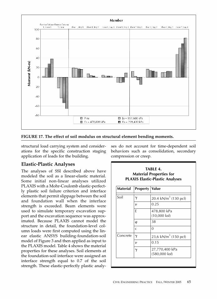
structural load carrying system and consider-ations for the specific construction stagingapplication of loads for the building.
Elastic-Plastic AnalysesThe analyses of SSI described above havemodeled the soil as a linear-elastic material.Some initial non-linear analyses utilizedPLAXIS with a Mohr-Coulomb elastic-perfect-ly plastic soil failure criterion and interfaceelements that permit slippage between the soiland foundation wall when the interfacestrength is exceeded. Beam elements wereused to simulate temporary excavation sup-port and the excavation sequence was approx-imated. Because PLAXIS cannot model thestructure in detail, the foundation-level col-umn loads were first computed using the lin-ear elastic ANSYS building-foundation-soilmodel of Figure 3 and then applied as input tothe PLAXIS model. Table 4 shows the materialproperties for these analyses. Soil elements atthe foundation-soil interface were assigned aninterface strength equal to 0.7 of the soilstrength. These elastic-perfectly plastic analy-
ses do not account for time-dependent soilbehaviors such as consolidation, secondarycompression or creep.
CIVIL ENGINEERING PRACTICE FALL/WINTER 2005 65
FIGURE 17. The effect of soil modulus on structural element bending moments.
TABLE 4.Material Properties for
PLAXIS Elastic-Plastic Analyses
Material Property Value
Soil � 20.4 kN/m3 (130 pcf)
� 0.25
E 478,800 kPa (10,000 ksf)
� 38
c 0
Concrete � 23,6 kN/m3 (150 pcf)
� 0.15
� 27,770,400 kPa(580,000 ksf)
These initial analyses showed that the elas-tic-plastic vertical stresses are more uniformlydistributed than the corresponding elastic val-ues, with the greatest differences in the outerquarters of the foundation. The horizontalstresses and shear contact stresses are similar-ly affected. The elastic-plastic vertical dis-placements are about 25 percent greater thanthe equivalent elastic values of Figure 13.However, these initial studies (described indetail by Alonge4) have not investigated theeffects of non-linear soil behavior on thestresses in the foundation mat or buildingframe.
Summary & ConclusionsA method was developed to model the effectsof SSI for tall buildings using a two-dimen-sional finite-element model. In order to repre-sent a three-dimensional structure in twodimensions, a unit-slice of the building wasmodeled. Continuous members (e.g., matfoundation, sub soils and floor slabs) requiredno scaling of material properties but the stiff-ness of discrete elements (e.g., beams andcolumns) was scaled over the entire bay spac-ing. A two-dimensional model would not beapplicable for situations without symmetry inthe third dimension.
This research has provided a comparison oftwo finite-element packages: ANSYS, a gener-al-purpose finite-element analysis package,and PLAXIS, a package used for geotechnicalengineering analysis. ANSYS provides a widevariety of options for the investigation of com-plex structural models and loading condi-tions. However, it is complicated to use, doesnot easily model the initial gravity body forcesof geotechnical engineering problems andrequires large amounts of computing power,file management and storage space. PLAXIS ismuch easier to use, has powerful automaticmesh generating capabilities and can easilymodel initial gravity body forces and non-linear soil behavior. However, PLAXIS cannotmodel complex structures and loadings indetail. Thus, the foundation-level columnloads were first computed by ANSYS usingthe detailed linear elastic building-founda-tion-soil model (see Figure 3) and then appliedas input loads to PLAXIS. The linear analyses
showed little difference between the contactstresses and foundation displacements com-puted by ANSYS and PLAXIS.
Analyses were performed on a structuralmodel subjected to three foundation conditions:
• pin-connected to a rigid foundation base;• pin-connected to a mat foundation bear-
ing on the surface of a linear elastic soil;and
• pin-connected to a mat foundationembedded within a linear elastic soil.
The linear analyses demonstrated the effectsof SSI on foundation settlements, foundationcontact stresses and stresses in the foundationmat and bending moments in the buildingframe.
Foundation Embedment. The embeddedfoundation (see Figure 6) settled less than thesurface foundation because of the net loadreduction due to the weight of the excavatedsoil, the smaller thickness of soil beneath thefoundation and the beneficial effects of con-finement. The ANSYS computations showthat horizontal contact stresses were greatlyreduced for the embedded foundationbecause of load transfer into the building’sbelow-grade foundation walls.
Stresses in the Foundation Mat. Bendingstresses are proportional to the general shapeof the mat foundation’s bending moment dia-gram. Significant stress concentrations werecomputed at column locations in the concretemat, compressive near the top of the mat (seeFigure 8) and tensile near the bottom of themat (see Figure 9). Compared to a 2.44-meter(8-foot) thick mat, a 1.83-meter (6-foot) matproduced slightly less uniform contact stress-es (see Figure 7) and significantly greaterstress concentrations (see Figures 8 and 9), butalmost identical lateral deflection of the build-ing centerline.4
Bending Moments in the Building Frame.Bending moments were computed at criticallocations in lower floors of the buildingframe shown by Figure 10. In general, themoments in the structural members are notvery different for the 2.44-meter (8-foot) and1.83-meter (6-foot) mats. Figure 11 shows thatan analysis in which the structure was
66 CIVIL ENGINEERING PRACTICE FALL/WINTER 2005
pinned to a rigid base underestimates thebending moments at the exterior columns ofthe first floor by a factor of 2 compared to theanalysis with SSI.
Effects of Soil Modulus, A decrease in soilmodulus from 957,600 kPa (20,000 ksf) to239,400 kPa (5,000 ksf) produced more uni-form vertical stress distributions with lesspronounced stress concentrations beneaththe columns (see Figure 12), proportionalincreases in building settlements (see Figure13) and proportional increases in the build-ing centerline deflection (see Figure 14). Thecompressive and tensile stress concentra-tions at the top and bottom of the concretemat (see Figures 15 and 16) more than dou-bled with decreasing soil modulus. Whenthe foundation and subsoil rigidity are notmodeled (pinned condition) with the build-ing, bending moments at the exteriorcolumns and beams can be underestimatedby factors of 2 to 3. Incorrect estimates ofsoil modulus can lead to large errors in thebending moments computed at critical loca-tions.
Effects of Non-Linear Soil Behavior. Theimportance of modeling soil with a non-linearelastic-plastic failure criterion such as theMohr-Coulomb elastic-perfectly plastic modelwas investigated. The elastic-perfectly plasticvertical stresses are more uniformly distrib-uted than the corresponding elastic valuesand the elastic-plastic vertical displacementsare about 25 percent greater than the equiva-lent elastic values. However, these initial stud-ies have not investigated the effects of non-linear soil behavior on the stresses in the foundation mat or building frame.
Importance of SSI. This research shows thatfor the type of structure studied, it is impor-tant to include the effects of SSI in computingbuilding response to the applied loads. In thisexample, the analyses of the building framemodel pinned to a rigid base greatly underes-timated the bending moments at the lowerfloors in the frame. The linear soil moduluswill also greatly affect the stresses in the foun-dation mat and at column locations in theframe. The effects of non-linear soil behavioron the building structural response may alsobe important but they have not been quanti-
fied in the preliminary non-linear computa-tions. These results show that it is important tomodel the foundation and deformable sub-soils with the building structure in order tocapture the effects of SSI on the building struc-tural response. This requirement implies aneed for improved coordination of both geo-technical and structural engineering researchand design studies, including advances infinite-element software packages such asANSYS and PLAXIS. Further studies are war-ranted to examine impact of construction stag-ing as part of the SSI analysis. The net sum ofthis work is a better understanding of build-ing behavior in comparison to traditionaldesign methods, leading to more efficientstructural designs.
NOTES — The finite-element software packagesused for this study are ANSYS 5.5[3] and PLAX-IS 7.1.1[7]. ANSYS, a general-purpose two- andthree-dimensional finite-element program devel-oped to analyze mechanical, thermal and struc-tural problems, offers numerous elements andloading conditions. However, ANSYS does notautomatically generate an initial geostatic stress-zero displacement condition. Rather, the initialstresses are calculated as the first of a number ofload sequences and the displacements caused bythe initial stresses must then be subtracted fromthe displacements computed for subsequent load-ings in order to determine the net displacementscaused by the non-geostatic loading. ANSYS wasused to model the detailed structural response ofthe model fifty-story building to applied loads in alinear elastic analysis. PLAXIS, a two-dimen-sional (axisymmetric or plane strain) finite-ele-ment program, was developed for geotechnicalapplications. The program calculates initial geo-static stresses, considers the effects of gravitybody forces and drainage conditions, and incorpo-rates a number of non-linear stress strain models.PLAXIS operates through an easy-to-use graphi-cal user interface and creates the finite-elementmodel according to user-specified requirements.However, the element selection and loading condi-tions are too limited for the detailed analysis ofbuilding structures. PLAXIS was used for verifi-cation of the ANSYS computations and for an ini-tial investigation on the effects of non-linear soilbehavior on building structural response.
CIVIL ENGINEERING PRACTICE FALL/WINTER 2005 67

LEWIS EDGERS is a Professor atTufts University, where he specializesin geotechnical engineering. He hasearned degrees at Tufts and theMassachusetts Institute of Technol-
ogy. He is a fellow of the American Society of CivilEngineers, past president of the Boston Society ofCivil Engineers and is a registered engineer in thestate of Massachusetts. His current research is inthe areas of soil-structure interaction and rainfall-induced landslides.
MASOUD SANAYEI is a Professor ofCivil and Environmental Engineer-ing at Tufts University. He has beenon the Tufts faculty since 1986 aftergraduating from the University of
California at Los Angeles. He is the Chair of theASCE Committee on Methods of Monitoring andEvaluating Structural Performance. Dr. Sanayeiconducts research in the field of condition assess-ment of bridges, nondestructive testing, soil-structure interaction, floor vibrations testing andevaluations, structural dynamics and earthquakeengineering.
JOSEPH L. ALONGE is currently aGeotechnical Engineer at Hardesty &Hanover, LLP. His responsibilitiesinclude the design and analysis ofdeep foundations for bridges and
earth-retaining structures. He has worked in thefield of Civil Engineering with involvement in sitedevelopment projects. He holds a M.S.C.E from
Tufts University and a B.C.E from the GeorgiaInstitute of Technology.
REFERENCES
1. Sanayei, M., Edgers, L., Alonge, J.L., & Kirshen,P., “Effects of Increased Wind Loads on a TallBuilding,” Civil Engineering Practice, Vol. 19, No. 1,2004.
2. Kowalczyk, R.M, ed., Structural Systems for TallBuildings, New York: McGraw Hill, 1995.
3. Commonwealth of Massachusetts, MassachusettsState Building Code, William Francis Galvin,Secretary, 1997.
4. Alonge, J.L., Modeling the Effects of Soil-StructureInteraction on a Fifty-Story Building, submitted to theDepartment of Civil and Environmental Engineer-ing, Tufts University, in partial fulfillment for thedegree of Master of Science, 2001.
5. Poulos, H.G., & Davis, E.H., Elastic Solutions forSoil and Rock Mechanics, New York: John Wiley &Sons, 1974.
6. Steinbrenner, W. “Tafeln zur Setzungsberech-nung,” Die Strasse, 1934. Also, in Proceedings of theFirst International Conference Foundation Engineering,Cambridge, 1936.
7. Christian, J.T., & Carrier, W.D., “Janbu, Bjerrum,and Kjaernsli’s Chart Reinterpreted,” CanadianGeotechnical Journal, 1978.
8. American Concrete Institute, Building CodeRequirements for Structural Concrete (ACI 318-95) andCommentary (ACI-318R-95), reported by ACICommittee 318, Standard Building Code, 1995.
68 CIVIL ENGINEERING PRACTICE FALL/WINTER 2005