model pl2000 portable lathe · 2020-03-02 · page 2 pl2000 operating manual 1.2 safety precautions...
TRANSCRIPT

P/N 30898 May 2019 Revision 6
PL2000
PORTABLE LATHE OPERATING MANUAL


P/N 30898, Rev. 6 Page A
©2019 CLIMAX or its subsidiaries. All rights reserved.
Except as expressly provided herein, no part of this manual may be reproduced, copied, transmitted, disseminated, downloaded, or stored in any storage medium, without the express prior written consent of CLIMAX. CLIMAX hereby grants permission to download a single copy of this manual and of any revision hereto onto an electronic storage medium to be viewed and to print one copy of this manual or any revision hereto, pro- vided that such electronic or printed copy of this manual or revision must contain the complete text of this copyright notice and provided further that any unauthorized commercial distribution of this manual or any revision hereto is prohibited.
At CLIMAX, we value your opinion.
For comments or questions about this manual or other CLIMAX documentation, please e-mail [email protected].
For comments or questions about CLIMAX products or services, please call CLIMAX or e-mail [email protected]. For quick and accurate service, please provide your representative with the following:
• Your name • Shipping address • Telephone number • Machine model • Serial number (if applicable) • Date of purchase
CLIMAX World Headquarters
2712 East 2nd Street Newberg, Oregon 97132 USA
Telephone (worldwide): +1-503-538-2815 Toll-free (North America): 1-800-333-8311 Fax: 503-538-7600
H&S Tool World Headquarters
715 Weber Dr. Wadsworth, OH 44281 USA
Telephone: +1-330-336-4550 Fax: 1-330-336-9159 hstool.com
CLIMAX | H&S Tool (UK Headquarters)
Unit 7 Castlehill Industrial Estate Bredbury Industrial Park Horsfield Way
Stockport SK6 2SU, UK Telephone: +44 (0) 161-406-1720
CLIMAX | H&S Tool (European Headquarters)
Am Langen Graben 8 52353 Düren, Germany Telephone: +49 24-219-1770 E-mail: [email protected]
CLIMAX | H&S Tool (Asia Pacific Head-
quarters)
316 Tanglin Road #02-01 Singapore 247978
Telephone: +65 9647-2289 Fax: +65 6801-0699
CLIMAX | H&S Tool (Middle East Headquarters)
Warehouse #5, Plot: 369 272 Um Sequim Road Al Quoz 4 PO Box 414 084 Dubai, UAE
Telephone: +971 04-321-0328

Page B PL2000 Operating Manual
CLIMAX WORLDWIDE LOCATIONS
P/N 30898, Rev. 6 Page C
LIMITED WARRANTY CLIMAX Portable Machine Tools, Inc. (hereafter referred to as “CLIMAX”) warrants that all new machines are free from defects in materials and workmanship. This warranty is available to the original purchaser for a period of one year after delivery. If the original purchaser finds any defect in materials or workmanship within the warranty period, the original purchaser should contact its factory representative and return the entire machine, shipping prepaid, to the factory. CLIMAX will, at its option, either repair or replace the defective machine at no charge and will return the machine with shipping prepaid. CLIMAX warrants that all parts are free from defects in materials and workmanship, and that all labor has been performed properly. This warranty is available to the customer purchasing parts or labor for a period of 90 days after delivery of the part or repaired machine or 180 days on used machines and components. If the customer purchasing parts or labor finds any defect in materials or workmanship within the warranty period, the purchaser should contact its factory representative and return the part or repaired machine, shipping pre- paid, to the factory. CLIMAX will, at its option, either repair or replace the defective part and/ or correct any defect in the labor performed, both at no charge, and return the part or repaired machine shipping prepaid. These warranties do not apply to the following:
• Damage after the date of shipment not caused by defects in materials or workmanship • Damage caused by improper or inadequate machine maintenance • Damage caused by unauthorized machine modification or repair • Damage caused by machine abuse • Damage caused by using the machine beyond its rated capacity
All other warranties, express or implied, including without limitation the warranties of merchantability and fitness for a particular purpose are disclaimed and excluded. Terms of sale
Be sure to review the terms of sale which appear on the reverse side of your invoice. These terms control and limit your rights with respect to the goods purchased from CLIMAX. About this manual
CLIMAX provides the contents of this manual in good faith as a guideline to the operator. CLIMAX cannot guarantee that the information contained in this manual is correct for applications other than the application described in this manual. Product specifications are subject to change without notice.

Page D PL2000 Operating Manual
CE DOCUMENTATION

P/N 30898, Rev. 6 Page i
TABLE OF CONTENTS 1 OVERVIEW .............................................................................................................................. 1
1.1 LIMITED WARRANTY ........................................................................ ERROR! BOOKMARK NOT DEFINED. 1.2 HOW TO USE THIS MANUAL ................................................................................................................ 1
1.2.1 Alerts 1 1.3 SAFETY PRECAUTIONS ....................................................................................................................... 2
2 CE ............................................................................................................................................ 4
2.1 AUDIBLE NOISE LEVELS ..................................................................................................................... 4 2.2 WARNING LABELS .............................................................................................................................. 4 2.3 MACHINE LOCK-OUT .......................................................................................................................... 6
3 INTRODUCTION ...................................................................................................................... 7
3.1 ABOUT THIS MANUAL .......................................................................................................................... 7 3.2 ABOUT THE CLIMAX MODEL PL2000 PORTABLE LATHE ....................................................................... 7 3.3 ELECTRIC LATHE ................................................................................................................................ 8 3.4 PNEUMATIC LATHE ........................................................................................................................... 10
4 SETUP ................................................................................................................................... 12
4.1 RECEIPT AND INSPECTION ................................................................................................................ 12 4.2 PREPARING THE MOUNTING FLANGE ................................................................................................. 12 4.3 CENTERING THE MACHINE ................................................................................................................ 13 4.4 MOTOR MOUNTING ........................................................................................................................... 13
4.4.1 Electric motor mounting 13 4.4.2 Air motor mounting 15
4.5 AIR POWER CONNECTION ................................................................................................................. 16 4.5.1 To start the machine: 17 4.5.2 To stop the machine: 17
4.6 TOOL BIT PREPARATION ................................................................................................................... 17 4.7 MANUAL AXIAL FEED ........................................................................................................................ 20
4.7.1 Setting rotational speed 20 4.7.2 Electric speed adjustment 20 4.7.3 Pneumatic speed adjustment 20
5 OPERATION .......................................................................................................................... 21
5.1 PRE-START CHECKS ......................................................................................................................... 21 5.1.1 General pre-start checks 21 5.1.2 Electric lathe pre-start checks 21 5.1.3 Pneumatic lathe pre-start checks 21
5.2 OPERATION ..................................................................................................................................... 22 5.3 TAPER ADJUSTMENT ........................................................................................................................ 23 5.4 SINGLE BOLT MOUNTING ADAPTER .................................................................................................... 23 5.5 SHAFT POLISHING ............................................................................................................................ 23 5.6 SETTING THE ABRASIVE BELT HOLDER .............................................................................................. 24 5.7 SPOT POLISHING .............................................................................................................................. 24 5.8 POLISHING THE ENTIRE SHAFT .......................................................................................................... 24
6 DISASSEMBLY ..................................................................................................................... 25
7 MAINTENANCE ..................................................................................................................... 26
7.1 RECOMMENDED LUBRICANTS ............................................................................................................ 26

Page ii PL2000 Operating Manual
7.2 MAIN BODY ...................................................................................................................................... 26 7.3 MOUNTING FLANGE .......................................................................................................................... 26 7.4 TURNING BAR ASSEMBLY .................................................................................................................. 26 7.5 ELECTRIC MOTOR ............................................................................................................................ 26 7.6 AIR MOTOR AND PNEUMATIC CONDITIONING UNIT ............................................................................... 27 7.7 PLANETARY HOUSING ....................................................................................................................... 27
8 STORAGE ............................................................................................................................. 28
8.2 LIST OF EXPLODED VIEWS AND PARTS ............................................................................................... 30

P/N 30898, Rev. 6 Page iii
LIST OF FIGURES FIGURE 1 – ELECTRIC PORTABLE LATHE ..................................................................................................................................... 8 FIGURE 2 – CONTROLLER 10 AMP 230V 50/60 HZ P/N 79218 ................................................................................................ 9 FIGURE 3 – PNEUMATIC PORTABLE LATHE (YOUR CONDITIONG UNIT MAY VARY FROM THE ILLUSTRATION). ........................................ 10 FIGURE 4 – (1) FEED RATE KNOB: CONTINUOUSLY VARIABLE FROM 0–0.025" (0–0.635 MM) PER REVOLUTION. (2) CRITERION STYLE
TOOL HEAD: (3) FEED ENGAGEMENT SHAFT: USE WITH THE HAND CRANK FOR MANUAL POSITIONING. ....................................... 11 FIGURE 5 – ELECTRIC PORTABLE LATHE CLEARANCE DIMENSIONS (INCHES/MM) ........................................................................... 14 FIGURE 6 – PNEUMATIC PORTABLE LATHE CLEARANCE DIMENSIONS (INCHES/MM) ....................................................................... 15 FIGURE 7- LOCKOUT VALVE .................................................................................................................................................. 16 FIGURE 8 – TOOL BIT GEOMETRY - INCH (MM) ......................................................................................................................... 19 FIGURE 9 – P/N 31594 BAR TURNING SUPPORT FEED ASSY ....................................................................................................... 31 FIGURE 10 – P/N 31594 BAR TURNING SUPPORT FEED ASSY PARTS LIST ..................................................................................... 32 FIGURE 11 – P/N 30333 ASSY PNEUMATIC POWER MODULE PL2000 ........................................................................................ 33 FIGURE 12 – P/N 78264 PNEUMATIC CONDITIONING UNIT 1/2 IN LOW PRES. ............................................................................ 34 FIGURE 13 – P/N78264 PNEUMATIC CONDITIONING UNIT 1/2 IN LOW PRES.PARTS LIST ............................................................... 35 FIGURE 14 – P/N78264 PNEUMATIC CONDITIONING UNIT 1/2 IN LOW PRES. DROPOUT SCHEMATIC............................................... 36 FIGURE 15 – P/N 29998 ASSY PNEUMATIC PL2000 ............................................................................................................... 37 FIGURE 16 – P/N 31586 ASSY MAIN BODY 2ND PL2000 .......................................................................................................... 38 FIGURE 17 – P/N 31590 SPACER ASSY 5-9 IN DIAMETER .......................................................................................................... 39 FIGURE 18 -- CONTROLLER SCHEMATIC 10 AMP 230 V 50/60 HZ CE 79218 ............................................................................. 40 FIGURE 19 – P/N 79218 CONTROLLER 10 AMP 230 V 50/60 HZ CE ....................................................................................... 41 FIGURE 20 – P/N 79218 CONTROLLER 10 AMP 230 V 50/60 HZ CE MULTIPLE MODEL .............................................................. 42 FIGURE 21 – P/N 79218 CONTROLLER 10 AMP 230 V 50/60 HZ CE MULTIPLE MODEL PARTS LIST ............................................... 43 FIGURE 22 – P/N 30572 SINGLE BOLT ADAPTER ASSY .............................................................................................................. 44 FIGURE 23 – P/N 30407 INDICATOR ASSY PL2000 ................................................................................................................ 45 FIGURE 24 – P/N 31585 ASSY MAIN BODY & BAR ASSY 2ND PL2000 ........................................................................................ 46 FIGURE 25 – P/N 30309 DRIVE ROTATIONAL PL2000 ELECTRIC 120V AND P/N 30816 DRIVE ROTATIONAL PL2000 230V ............ 47 FIGURE 26 – P/N 31584 MODEL PL2000 PORTABLE LATE AIR 2ND ........................................................................................... 48

Page iv PL2000 Operating Manual
LIST OF TABLES TABLE 1. RISK ASSESSMENT CHECKLIST BEFORE SET-UP ........................................................................................................... 3 TABLE 2. RISK ASSESSMENT CHECKLIST AFTER SET-UP .............................................................................................................. 3 TABLE 3 – DESCRIPTION OF LABELS ......................................................................................................................................... 4 TABLE 4 – RECCOMENDED LUBRICANTS .................................................................................................................................. 26

P/N 30898, Rev. 6 Page 1
1 OVERVIEW
1.1 How to Use This Manual
1.1.1 Alerts
Pay careful attention to the alertsappearing in this manual. Alert types are defined in the following examples.
DANGER concerns a condition, procedure, or practice that, if not avoided or strictly observed, WILL result in injury or loss of life.
WARNING concerns a condition, procedure, or practice that, if not avoided or strictly observed, COULD result in injury or loss of life.
CAUTION concerns a condition, procedure, or practice that, if not avoided or strictly observed, could result in minor or moderate injury.
NOTICE concerns a condition, procedure, or practice worthy of special attention.
TIP: A tip provides additional information that can aid in completion of a task.

Page 2 PL2000 Operating Manual
1.2 Safety Precautions
Climax Portable Machining and Welding Systems leads the way in promoting the safe use of portable machine tools. Safety is a joint effort. You, the machine operator, must do your part by being aware of your work environment and closely following the operating procedures and safety precautions contained in this manual, as well as your employer’s safety guidelines. Observe the following safety precautions when operating or working around the machine.
Training – Before operating this or any machine tool, you should receive instruction from a qualified trainer. Contact Climax for machine-specific training information.
Intended Use – Use this machine in accordance with the instructions and precautions in this manual. Do not use this machine for any purpose other than its intended use as described in this manual.
Personal Protective Equipment – Always wear the appropriate personal protective gear when operating this or any other machine tool. Eye and ear protection are required when operating or working around the machine. Flame-resistant clothing with long sleeves and legs is recommended when operating the machine, as hot flying chips from the workpiece may burn or cut bare skin.
Work Area – Keep the work area around the machine clear of clutter. Keep all cords and hoses away from the work area when operating the machine.
Moving Parts – Except for operating controls, avoid contact with moving parts by hands or tools during machine operation. Secure hair, clothing, jewelry, and pocket items to prevent them from becoming entangled in moving parts.
1.3 Risk assessment and hazard mitigation Machine Tools are specifically designed to perform precise material-removal operations. Stationary Machine Tools include lathes and milling machines and are typically found in a machine shop. They are mounted in a fixed location during operation and are considered to be a complete, self-contained machine. Stationary Machine Tools achieve the rigidity needed to accomplish material-removal operations from the structure that is an integral part of the machine tool. In contrast, Portable Machine Tools are designed for on-site machining applications. They typically attach directly to the workpiece itself, or to an adjacent structure, and achieve their rigidity from the structure to which it is attached. The design intent is that the Portable Machine Tool and the structure attached to it become one complete machine during the material-removal process. To achieve the intended results and to promote safety, the operator must understand and follow the design intent, set-up, and operation practices that are unique to Portable Machine Tools.

P/N 30898, Rev. 6 Page 3
The operator must perform an overall review and on-site risk assessment of the intended application. Due to the unique nature of portable machining applications, identifying one or more hazards that must be addressed is typical. When performing the on-site risk assessment, it is important to consider the Portable Machine Tool and the workpiece as a whole.
1.4 Risk assessment checklist Use these checklists as part of your on-site risk assessment and include any additional considerations that may pertain to your specific application.
TABLE 1. RISK ASSESSMENT CHECKLIST BEFORE SET-UP
Before Set-up
I took note of all the warning labels on the machine.
I removed or mitigated all identified risks (such as tripping, cutting, crushing, entanglement, shearing, or falling objects).
I considered the need for personnel safety guarding and installed any necessary guards.
I read the Machine Assembly instructions and took inventory of all the items required but not supplied.
I created a lift plan, including identifying the proper rigging, for each of the setup lifts required during the setup of the support structure and machine.
I located the fall paths involved in lifting and rigging operations. I have taken precautions to keep workers away from the identified fall path.
I considered how this machine operates and the best placement for the controls, cabling, and the operator.
I evaluated and mitigated any other potential risks specific to my work area.
TABLE 2. RISK ASSESSMENT CHECKLIST AFTER SET-UP
After Set-up
I checked that the machine is safely and the potential fall path is clear. If the machine is elevated, I checked that the machine is safeguarded against falling.
I identified all possible pinch points, such as those caused by rotating parts, and informed the affected personnel.
I planned for containment of any chips or swarf produced by the machine.
I followed the Maintenance Intervals with the recommended lubricants.
I checked that all affected personnel have the recommended personal protective equipment, as well as any equipment required by the site or other regulations.
I checked that all affected personnel understand the danger zone and are clear of it.
I evaluated and mitigated any other potential risks specific to my work area.

Page 4 PL2000 Operating Manual
2 CE Recommended air pressure: 90 psi (DO NOT EXCEED 120 psi) Temperature maximum: 25.7̊ C (Electric)
2.1 Audible Noise Levels
Electric Drive Option: ▪ Declared Sound Power Level is 80 dBA ▪ Declared Operator Sound Pressure Level is 79 dBA ▪ Declared Bystander Sound Pressure Level is 74 dBA
2.2 Warning labels
The following warning labels should be on your machine. If any are defaced or missing, contact CLIMAX immediately for replacements.
TABLE 3 – DESCRIPTION OF LABELS
P/N 29154
CLIMAX serial number, year and model number plate.
P/N 29152
Label mass tag Weight =Approx. 100Kg
P/N 590440
Label safety warning cirlce read the manual
P/N78741
Label safety warning hand crush
P/N 59037

P/N 30898, Rev. 6 Page 5
P/N 78742
Label safety warning entanglement of hand, or rotating shaft warning
P/N 78748
Label safety warning eye protection
P/N 78824
Label saftey warning do not expose to water
P/N 80510 label safety warning cutting of fingers, or rotating blade
P/N 78593 Label safety warning electrical shock or electrocution
P/N 81008 label safety warning eye and ear protection required
P/N 80207 lable safety warning entanglement rotating shaft

Page 6 PL2000 Operating Manual
2.3 Machine Lock-Out
Air shutoff in the operating position (UP) To lockout the machine, Push down on the lockout and insert locks into the openings at the bottom of the air shutoff on the air intake side of the pneumatic conditioning unit.
Recommended air pressure: 90 psi (DO NOT EXCEED 120 psi)
P/N 30898, Rev. 6 Page 7
3 INTRODUCTION
3.1 About this manual
This manual describes how to use your Model PL2000 Portable Lathe.
CAUTION To avoid severe personal injury, read and understand all instructions and warnings before operating this machine.
3.2 About the PL2000
The PL2000 Portable Lathe mounts to the end of the shaft. It is electrically or pneumatically powered. The compact design makes it an ideal on-site maintenance tool. The machine turns shafts 1.5" to 5" (38.1 - 127 mm) and up to 9" (228.6 mm) diameter with optional spacer assembly. The Model PL2000 has a reach of 12.5" (317.5 mm).
The PL2000 Porable Lathe machine consists of:
• Main Body Assembly
• Turning Bar Assembly
• Electric Motor Assembly (electric model only)
• Electric Planetary Housing Assembly (electric model only)
• Air Motor Assembly (air model only)
• Pneumatic Planetary Housing Assembly (air model only)
• Pneumatic Conditioning Unit (air model only)
• Tool Kit including Operating Manual
Exploded-view drawings and parts lists are included with this manual.
NOTICE The PL2000 Portable Lathe machine must be rotating counter-clockwise (as viewed from the back of the motor) while machining. Do not rotate the PL2000 clockwise.

Page 8 PL2000 Operating Manual
3.3 Electric lathe
The electric PL2000 Portable Lathe has a 9 amp electric motor. The motor may be either 120 volt or 230 volt, and it provides 780 no-load rpm and 510 load rpm. Check the serial number plate on the motor to find the voltage. The motor operates on 50 or 60 cycles AC current. A control pendant adjusts the motor speed. The control pendant runs the motor at 0-70% of the maximum rpm.
FIGURE 1 – ELECTRIC PORTABLE LATHE
CAUTION The ON/OFF and reverse switches on the motor have been disabled for this machine; the motor is controlled from the control pendant. Any attempt to re-
wire these cables might result in damage to the machine or the operator.

P/N 30898, Rev. 6 Page 9
FIGURE 2 – CONTROLLER 10 AMP 230V 50/60 HZ P/N 79218
The coltrol pendant for this machine is hown in Figure 2.

Page 10 PL2000 Operating Manual
3.4 Pneumatic lathe
The pneumatic PL2000 Portable Lathe has a 1.22 HP (0.91 kW) air motor. Use the needle valve to adjust the motor speed.
FIGURE 3 – PNEUMATIC PORTABLE LATHE (YOUR CONDITIONG UNIT MAY VARY FROM THE
ILLUSTRATION).

P/N 30898, Rev. 6 Page 11
CAUTION Recommended operating pressure is 90 psi (620 kPa). DO NOT EXCEED 120 PSI (827 KPA)!
FIGURE 4 – (1) FEED RATE KNOB: CONTINUOUSLY VARIABLE FROM 0–0.025" (0–0.635 MM) PER REVOLUTION. (2) CRITERION STYLE TOOL HEAD: (3) FEED ENGAGEMENT SHAFT:
USE WITH THE HAND CRANK FOR MANUAL POSITIONING.
3
2
1

Page 12 PL2000 Operating Manual
4 SETUP
4.1 Receipt and Inspection
Your CLIMAX product was inspected and tested prior to shipment, and packaged for normal shipment conditions. CLIMAX does not guarantee the condition of your machine upon delivery. When you receive your CLIMAX product, perform the following receipt checks.
1. Inspect the shipping container(s) for damage. 2. Check the contents of the shipping container(s) against the included invoice to
ensure that all components have been shipped. 3. Inspect all components for damage.
Contact CLIMAX immediately to report damaged or missing components.
CAUTION To avoid bodily injury from moving machinery, turn off and disconnect all power cords before setting up the machine.
4.2 Preparing the mounting flange
The mounting flange of the PL2000 is 3.75" (95.25 mm) outside diameter and has four .40" (87.3 mm) diameter clearance holes for 3/8-24 mounting bolts. These holes are evenly spaced on a 3.03" (76.96 mm) diameter bolt circle. Between each of the clearance holes is a 3/8-24 tapped hole to accept jacking screws for leveling the machine.
1. Clean the end of the shaft and the face of the mounting flange.
NOTICE Dirt, burrs, and grease on either the end of the work piece or the face of the flange will keep the flange from mounting properly.
2. Remove the motor, counterweights, turning bar, bar support and spacer assembly.
3. Loosely attach the machine flange to the end of the shaft. 4. Attach the turning bar, bar support, counterweights, and spacer assembly.
Tighten the four bolts holding the bar support to the main body to 100 in/lbs.

P/N 30898, Rev. 6 Page 13
4.3 Centering the machine
1. Crank the turning bar in until the tool head is as close as possible to the main body of the machine.
2. Attach a dial indicator to the tool head. Indicate as close to the center of the turning arm as possible.
3. Manually rotate the machine around the shaft. Using a soft mallet, tap the machine mounting flange until it is centered.
4. Snug the flange mounting screws. 5. Crank the turning bar out until the tool head and dial indicator are as far as
possible from the machine. 6. Manually rotate the machine around the shaft. Adjust the three 3/8-24 jacking
screws to align the machine. 7. Repeat steps #3 through #6 until the machine is centered. 8. Tighten all mounting screws.
WARNING To avoid serious personal injury, keep clear of the hoist and the machine during setup.
4.4 Motor mounting
NOTICE The PL2000 Portable Lathe machine must be rotating counter-clockwise (as viewed from the back of the motor) while machining. Do not rotate the PL2000 clockwise.
4.4.1 Electric motor mounting
1. Insert the planetary housing assembly into the internal ring gear of the main body. Tighten the five 1/4-20 socket head cap screws to 150 in-lbs (17 Nm).
2. Mount the electric motor mount onto the planetary housing. Tighten the five mounting screws to 150 in-lb (17 Nm).
3. Insert the electric motor assembly into the planetary gear housing. The electric motor assembly may need to be rotated slightly so that the gears mesh. Tighten the motor mount screws to 300 in-lb (34 Nm).

Page 14 PL2000 Operating Manual
FIGURE 5 – ELECTRIC PORTABLE LATHE CLEARANCE DIMENSIONS (INCHES/MM)

P/N 30898, Rev. 6 Page 15
4.4.2 Air motor mounting
CAUTION To avoid serious personal injury from moving machinery, turn off and lock out the motor before connecting the air supply. Ensure that the needle valve is extended far enough from the machine for safe adjustment while in motion.
1. Insert the planetary housing assembly into the internal ring gear. Tighten the five mounting screws to 150 in-lb (17 Nm).
2. Mount the air motor assembly to the planetary housing. Tighten the two mounting screws to 150 in-lb (17 Nm).
FIGURE 6 – PNEUMATIC PORTABLE LATHE CLEARANCE DIMENSIONS (INCHES/MM)

Page 16 PL2000 Operating Manual
CAUTION To avoid serious personal injury from moving machinery, turn off the motor BEFORE plugging it in.
3. Turn off the motor. 4. Turn the variable speed controller counterclockwise all the way. 5. Plug the machine into a properly grounded outlet.
CAUTION To avoid injury by shock or explosion, do not operate electric motors in damp or explosive conditions.
4.5 Air power connection
CAUTION To prevent serious injury from moving machinery during setup or adjustment, use quick disconnect fittings between the air supply line and the needle valve. Close and lock out all air valves before connecting the air supply line to the motor.
FIGURE 7- LOCKOUT VALVE
The PL2000 Portable Lathe has a 1.22 hp (.91 kW) air motor. Adjust motor speed using the needle valve. The air filter and lubricator (pneumatic conditioning unit) supplied with the machine must be used or the warranty is void. The lubricator should be set to deliver oil at a rate of 2-4 drops per minute.

P/N 30898, Rev. 6 Page 17
CAUTION To prevent damage to the machine, use the filter and lubricator provided.
The PL2000 Portable Lathe is equipped with a needle valve/lockout valve assembly.
NOTICE Air line connections should be made with nonrestrictive air fittings of not less than 3/8" dia.
4.5.1 To start the machine:
1. Turn the needle valve clockwise all the way. No colored bands will be visible when the valve is completely closed.
2. Push the emergency stop lever down until the word CLOSED and the lockout can be seen from the bottom of the valve. Be sure the lever is pushed all the way.
CAUTION To prevent serious injury from moving machinery, secure the machine to the work piece before connecting the air supply.
3. Push the emergency stop lever up until the word OPEN can be seen from the top of the valve. Be sure the lever is pushed all the way.
4. Slowly turn the needle valve counterclockwise until the machine is turning at the desired speed. The more colored bands you see, the faster the machine speed.
CAUTION In case of emergency push the emergency stop lever closed.
4.5.2 To stop the machine:
1. Turn the needle valve clockwise all the way. No colored bands will be visible when the valve is completely closed.
2. Push the emergency stop lever down until the word CLOSED and the lockout can be seen from the bottom of the valve. Be sure the lever is pushed all the way. Lock out the machine with a padlock.
4.6 Tool bit preparation
1. Grind a 1/2" round tool bit. See Figure 8 for grinding information.
Page 18 PL2000 Operating Manual
NOTICE High-speed tool bits may perform better than carbide tools. Carbide bits tend to ride up or skid on the surface.
CAUTION Correct tool bit geometry is critical to the performance of the machine. Never use tool bits without checking their geometry.
2. Check the geometry of the HSS tool bit against the tool geometry diagrams, next page. Tool bits with low clearance angles may reduce chatter and cut better. Exact tooling geometry also depends on the type of material being cut.
3. Center the tool head's moveable part with the stationary part. 4. Move the tool holder so that it is over the work piece. 5. Slide the tool bit into the tool head until the tool bit touches the work piece.
Tighten the three set screws to secure the tool.
CAUTION To prevent serious bodily injury from moving machinery, turn off and disconnect the power before inserting or adjusting the tool bit.
6. Reposition the tool by using the manual hand crank so the tool is off the end of the work piece.
7. Adjust the tool downward (clockwise) to the desired depth of cut. The dial is in .001" (.025 mm) graduations on the diameter. Therefore, turning the dial .020" (.508 mm) down will remove .020" (.508 mm) off the diameter or be a .010" (.254 mm) depth of cut.

P/N 30898, Rev. 6 Page 19
FIGURE 8 – TOOL BIT GEOMETRY - INCH (MM)

Page 20 PL2000 Operating Manual
4.7 Manual Axial feed
1. Using the crank handle, move the tool bit to the end of the work piece. 2. Engage the feed by pushing in the end of the pinion shaft until the pin engages
with the slot. 3. Adjust the feed rate by turning the adjustment knob. Clockwise slows the feed
rate and counterclockwise increases the feed rate.
4.7.1 Setting rotational speed
CAUTION To prevent serious bodily injury from moving machinery, turn off and disconnect the power before adjusting machine feeds.
Rotational speed rate is variable up to 95 rpm.
NOTICE The PL2000 Portable Lathe machine must be rotating counter-clockwise (as viewed from the back of the motor) while machining. Do not rotate the PL2000 clockwise.
4.7.2 Electric speed adjustment
To adjust the speed on electric machines, slowly turn the speed control.
4.7.3 Pneumatic speed adjustment
To adjust the speed on pneumatic machines, slowly turn the needle valve.

P/N 30898, Rev. 6 Page 21
5 OPERATION
5.1 Pre-start checks
CAUTION To prevent serious bodily injury from moving machinery, turn off and disconnect the machine before performing pre-start checks.
5.1.1 General pre-start checks
1. Be sure tool bits are sharp. 2. Check that all moving parts move freely.
5.1.2 Electric lathe pre-start checks
1. Inspect electrical parts for damage. 2. Be sure power is OFF before plugging in unit. 3. Plug the machine into a grounded outlet.
5.1.3 Pneumatic lathe pre-start checks
1. Fill the air lubricator with air oil. Use an air oil that has antioxidants and rust inhibitors such as Marvel Air Tool Oil. Set the lubricator to deliver oil at a rate of 2-4 drops per minute.
2. Drain the air filter. 3. Push the emergency stop lever down until the word CLOSED and the lockout
can be seen from the bottom of the valve. Be sure the lever is pushed all the way. 4. Turn the needle valve clockwise all the way. You will not be able to see any of
the colored bands when the valve is completely closed. 5. Check that the in-line air pressure is 90 psi (620 kPa). Be sure air lines are not
restricted or damaged.

Page 22 PL2000 Operating Manual
5.2 Operation
CAUTION To protect yourself from flying chips and excessive noise, wear eye and ear protection while operating the machine.
NOTICE The PL2000 Portable Lathe machine must be rotating counter-clockwise (as viewed from the back of the motor) while machining. Do not rotate the PL2000 clockwise.
1. Be sure the power is off. 1. Using the crank handle, retract the turning bar until the tool head is as close to
the machine as possible. 2. Crank the turning bar out until the cutter is just over the shaft.
CAUTION Because the feed moves the cutter away from the mounting flange, start the cut with the bar fully retracted.
3. Turn the depth adjustment knob clockwise until the cutter just touches the shaft. 4. Retract the turning bar until the cutter just clears the end of the shaft. 5. Turn the depth adjusting knob to set the tool bit to the desired depth. Turning the
knob clockwise adjusts the tool downward. The dial is in .001" (.025 mm) graduations on the diameter.
6. Set the axial feed lever to desired feed rate. Clockwise slows the feed rate down and counterclockwise speeds the feed rate up.
7. Engage the feed by pushing the end of the pinion shaft in until the pin in the shaft engages with the detente slot.
8. Remove the hand crank from the machine. 9. Start the machine. To adjust the speed on electric machines, slowly turn the
speed control. To adjust the speed on pneumatic machines, slowly open or close the needle valve.
10. After the desired length of shaft has been turned, gradually turn the motor speed down until the machine stops rotating.
11. Using the hand crank, retract the cutter. 12. Repeat Steps #1 through #12 until the shaft is turned to the desired size or finish.
TIP: For finer finish cuts, set the tool bit for a shallower cut and run the machine at a slower feed rate.

P/N 30898, Rev. 6 Page 23
13. Shaft polishing can also improve the finish and minimize taper. For more information, see “Shaft Polishing” on page 27.
5.3 Taper adjustment
The PL2000 Portable Lathe is equipped with a feature for fine adjustment of the turning bar, and improve a taper condition in the work piece.
1. Perform a test cut on your work piece. Measure both ends of the test cut with a micrometer to check for taper.
2. Adjust taper with the four jacking screws accessible from the top of the turning bar support, and four mounting screws that hold the turning bar support to the main body of the machine.
3. Mount a dial indicator to the bar, with the stylus of the indicator against the test cut. Tighten either the two front or the two rear jacking screws, and slightly loosen the corresponding mounting bolts, to allow for bar movement. Observe the dial indicator movement for desired movement of the bar (indicator movement should be about half of test cut taper).
CAUTION Do not over-tighten the turning bar support screws beyond 10 ft-lbs, or binding of the turning bar may occur, resulting in damage to the machine. For finer adjustment, sections of the shaft can be polished to more closely match diameters of other sections of the bar.
5.4 Single bolt mounting adapter
The single bolt mounting adapter secures the PL2000 on shafts under 3.75" (95.25 mm) diameter. Drill and tap a 5/8-11 hole in the end of the work piece. Be sure that thread is at least 1" (25.4 mm) deep. Mount the adapter, then attach the machine mounting flange to the adapter as described in Section "Setup".
5.5 Shaft polishing
With the abrasive belt holder (included with the machine) and an abrasive belt (user supplied), the PL2000 Portable Lathe can polish shafts.
CAUTION To avoid serious personal injury from moving machinery, turn off and disconnect the power before setting up the abrasive belt.

Page 24 PL2000 Operating Manual
5.6 Setting the abrasive belt holder
1. Attach an abrasive belt holder to the end of the turning bar. 2. Wrap an abrasive belt around the shaft and through the slot into the holder. 3. Using a wrench, tighten the abrasive belt holder until the belt is snug against the
work piece. Tighten the set screw.
5.7 Spot polishing
1. Position the belt as desired on the shaft. 2. Start the machine. 3. Run the machine until the shaft has the desired finish. Spot polishing can also be
used to minimize taper along the length of a shaft.
5.8 Polishing the entire shaft
1. Position the belt on the end of the shaft. 2. Engage the feed system. 3. Start the machine. The machine will automatically feed the belt along the shaft.

P/N 30898, Rev. 6 Page 25
6 DISASSEMBLY
CAUTION To prevent serious bodily injury from moving machinery, turn off and lock out and disconnect the power supply before disconnecting the machine.
To disassemble the PL2000 Portable Lathe: 1. Turn off and disconnect the power supply. 2. Turn the depth adjustment knob counterclockwise to retract the cutter. 3. Remove the tool. 4. Remove the motor from the planetary housing. 5. Remove the bar support and turning bar. 6. Remove the counterweight. 7. Secure the machine with a hoist. 8. Remove the machine from the shaft.
Page 26 PL2000 Operating Manual
7 MAINTENANCE
7.1 Recommended lubricants
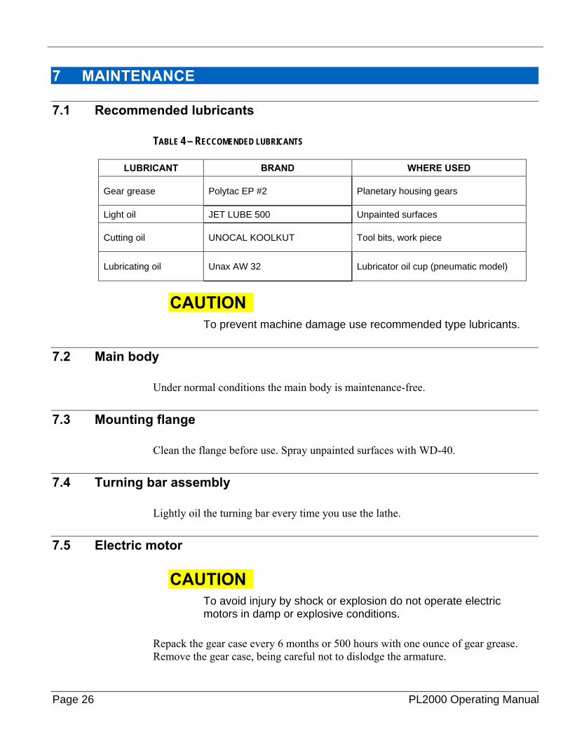
TABLE 4 – RECCOMENDED LUBRICANTS
LUBRICANT BRAND WHERE USED
Gear grease Polytac EP #2 Planetary housing gears
Light oil JET LUBE 500 Unpainted surfaces
Cutting oil UNOCAL KOOLKUT Tool bits, work piece
Lubricating oil Unax AW 32 Lubricator oil cup (pneumatic model)
CAUTION To prevent machine damage use recommended type lubricants.
7.2 Main body
Under normal conditions the main body is maintenance-free.
7.3 Mounting flange
Clean the flange before use. Spray unpainted surfaces with WD-40.
7.4 Turning bar assembly
Lightly oil the turning bar every time you use the lathe.
7.5 Electric motor
CAUTION To avoid injury by shock or explosion do not operate electric motors in damp or explosive conditions.
Repack the gear case every 6 months or 500 hours with one ounce of gear grease. Remove the gear case, being careful not to dislodge the armature.
P/N 30898, Rev. 6 Page 27
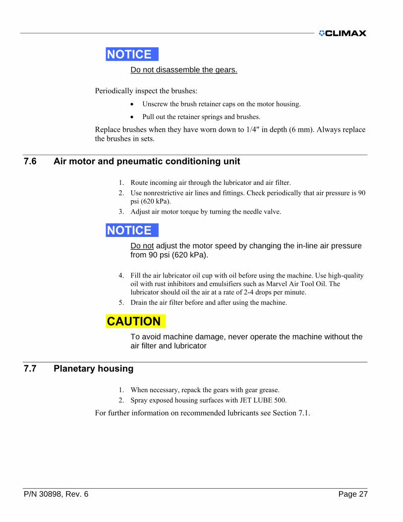
NOTICE Do not disassemble the gears.
Periodically inspect the brushes: • Unscrew the brush retainer caps on the motor housing.
• Pull out the retainer springs and brushes.
Replace brushes when they have worn down to 1/4" in depth (6 mm). Always replace the brushes in sets.
7.6 Air motor and pneumatic conditioning unit
1. Route incoming air through the lubricator and air filter. 2. Use nonrestrictive air lines and fittings. Check periodically that air pressure is 90
psi (620 kPa). 3. Adjust air motor torque by turning the needle valve.
NOTICE Do not adjust the motor speed by changing the in-line air pressure from 90 psi (620 kPa).
4. Fill the air lubricator oil cup with oil before using the machine. Use high-quality oil with rust inhibitors and emulsifiers such as Marvel Air Tool Oil. The lubricator should oil the air at a rate of 2-4 drops per minute.
5. Drain the air filter before and after using the machine.
CAUTION To avoid machine damage, never operate the machine without the air filter and lubricator
7.7 Planetary housing
1. When necessary, repack the gears with gear grease. 2. Spray exposed housing surfaces with JET LUBE 500.
For further information on recommended lubricants see Section 7.1.

Page 28 PL2000 Operating Manual
8 STORAGE Proper storage of the PL2000 Portable Lathe Portable Lathe will prevent undue deterioration or damage.
• Before storing the machine, clean it with solvent to remove grease, metal chips, and moisture.
• Drain the air filter on pneumatic machines.
• Spray the machine with a moisture-protective material (JET LUBE 500 for short storage, LPS3e for long storage) to prevent rusting.
• Store the machine in the crate provided.
• Place desiccant bags or vapor wrap around the machine to absorb moisture.
Call CLIMAX to replace a storage containter (P/N 16783).
P/N 30898, Rev. 6 Page 29
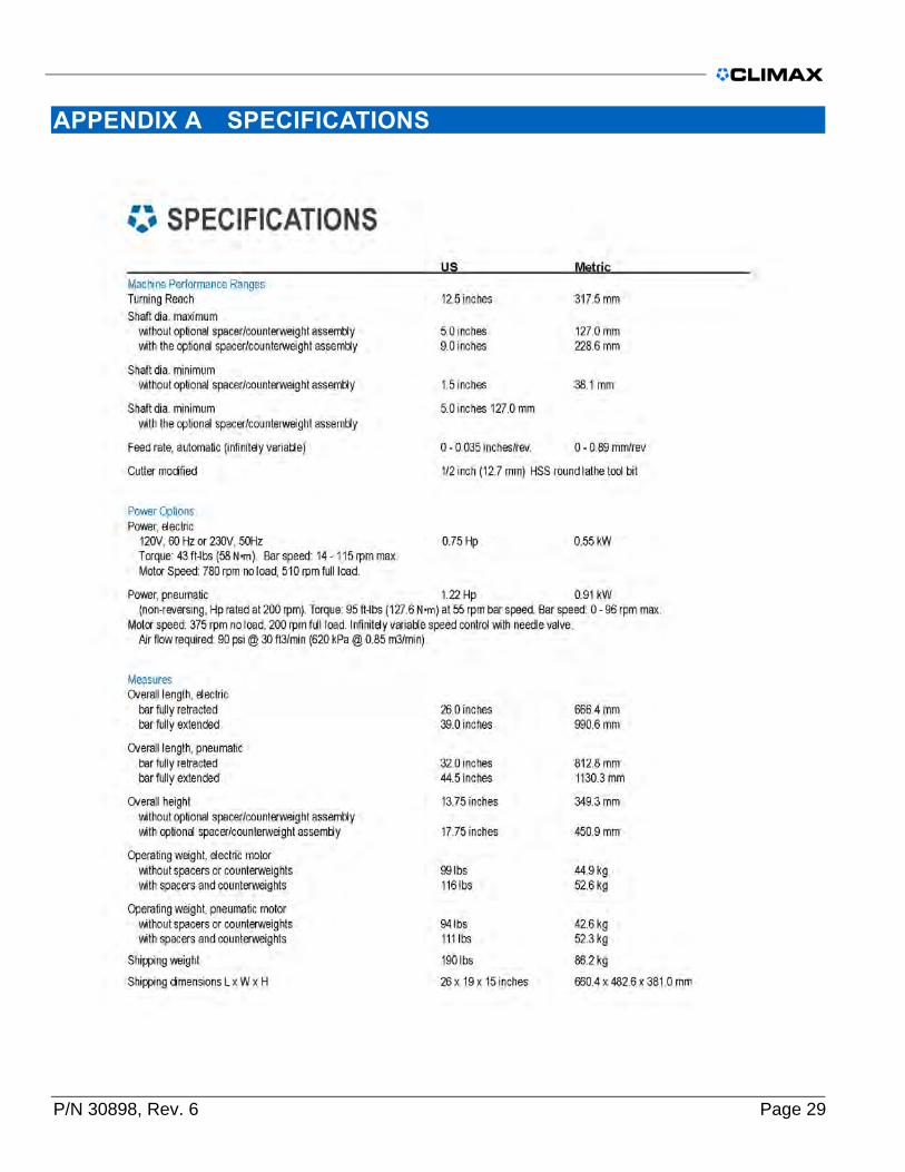
APPENDIX A SPECIFICATIONS

Page 30 PL2000 Operating Manual
APPENDIX B EXPLODED VIEWS AND PARTS
NOTICE The following diagrams and parts lists are for reference purposes only. The machine Limited Warranty is void if the machine has been tampered with by anyone who has not been authorized in writing by CLIMAX to perform service on the machine.
8.2 List of exploded views and parts
P/N 59037 ......................................................................................................................................................................... 4 FIGURE 2 – CONTROLLER 10 AMP 230V 50/60 HZ P/N 79218 ................................................................................................ 9 FIGURE 5 – ELECTRIC PORTABLE LATHE CLEARANCE DIMENSIONS (INCHES/MM) ........................................................................... 14 FIGURE 6 – PNEUMATIC PORTABLE LATHE CLEARANCE DIMENSIONS (INCHES/MM) ....................................................................... 15 FIGURE 7- LOCKOUT VALVE .................................................................................................................................................. 16 FIGURE 8 – TOOL BIT GEOMETRY - INCH (MM) ......................................................................................................................... 19 TABLE 4 – RECCOMENDED LUBRICANTS................................................................................................................................... 26 FIGURE 9 – P/N 31594 BAR TURNING SUPPORT FEED ASSY ....................................................................................................... 31 FIGURE 10 – P/N 31594 BAR TURNING SUPPORT FEED ASSY PARTS LIST ..................................................................................... 32 FIGURE 11 – P/N 30333 ASSY PNEUMATIC POWER MODULE PL2000 ........................................................................................ 33 FIGURE 12 – P/N 78264 PNEUMATIC CONDITIONING UNIT 1/2 IN LOW PRES. ............................................................................. 34 FIGURE 13 – P/N78264 PNEUMATIC CONDITIONING UNIT 1/2 IN LOW PRES.PARTS LIST ............................................................... 35 FIGURE 14 – P/N78264 PNEUMATIC CONDITIONING UNIT 1/2 IN LOW PRES. DROPOUT SCHEMATIC ............................................... 36 FIGURE 15 – P/N 29998 ASSY PNEUMATIC PL2000 ................................................................................................................ 37 FIGURE 16 – P/N 31586 ASSY MAIN BODY 2ND PL2000 ........................................................................................................... 38 FIGURE 17 – P/N 31590 SPACER ASSY 5-9 IN DIAMETER .......................................................................................................... 39 FIGURE 18 -- CONTROLLER SCHEMATIC 10 AMP 230 V 50/60 HZ CE 79218 ............................................................................. 40 FIGURE 19 – P/N 79218 CONTROLLER 10 AMP 230 V 50/60 HZ CE ....................................................................................... 41 FIGURE 20 – P/N 79218 CONTROLLER 10 AMP 230 V 50/60 HZ CE MULTIPLE MODEL .............................................................. 42 FIGURE 21 – P/N 79218 CONTROLLER 10 AMP 230 V 50/60 HZ CE MULTIPLE MODEL PARTS LIST ............................................... 43 FIGURE 22 – P/N 30572 SINGLE BOLT ADAPTER ASSY .............................................................................................................. 44 FIGURE 23 – P/N 30407 INDICATOR ASSY PL2000 ................................................................................................................ 45 FIGURE 24 – P/N 31585 ASSY MAIN BODY & BAR ASSY 2ND PL2000 ........................................................................................ 46 FIGURE 25 – P/N 30309 DRIVE ROTATIONAL PL2000 ELECTRIC 120V AND P/N 30816 DRIVE ROTATIONAL PL2000 230V ............ 47 FIGURE 26 – P/N 31584 MODEL PL2000 PORTABLE LATE AIR 2ND ............................................................................................ 48
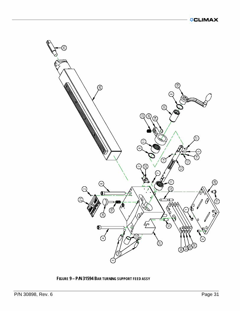
P/N 30898, Rev. 6 Page 31
FIGURE 9 – P/N 31594 BAR TURNING SUPPORT FEED ASSY

Page 32 PL2000 Operating Manual
FIGURE 10 – P/N 31594 BAR TURNING SUPPORT FEED ASSY PARTS LIST

P/N 30898, Rev. 6 Page 33
FIGURE 11 – P/N 30333 ASSY PNEUMATIC POWER MODULE PL2000

Page 34 PL2000 Operating Manual
FIGURE 12 – P/N 78264 PNEUMATIC CONDITIONING UNIT 1/2 IN LOW PRES.

P/N 30898, Rev. 6 Page 35
FIGURE 13 – P/N78264 PNEUMATIC CONDITIONING UNIT 1/2 IN LOW PRES.PARTS LIST

Page 36 PL2000 Operating Manual
FIGURE 14 – P/N78264 PNEUMATIC CONDITIONING UNIT 1/2 IN LOW PRES. DROPOUT SCHEMATIC

P/N 30898, Rev. 6 Page 37
FIGURE 15 – P/N 29998 ASSY PNEUMATIC PL2000

Page 38 PL2000 Operating Manual
FIGURE 16 – P/N 31586 ASSY MAIN BODY 2ND PL2000

P/N 30898, Rev. 6 Page 39
FIGURE 17 – P/N 31590 SPACER ASSY 5-9 IN DIAMETER

Page 40 PL2000 Operating Manual
FIGURE 18 -- CONTROLLER SCHEMATIC 10 AMP 230 V 50/60 HZ CE 79218

P/N 30898, Rev. 6 Page 41
FIGURE 19 – P/N 79218 CONTROLLER 10 AMP 230 V 50/60 HZ CE

Page 42 PL2000 Operating Manual
FIGURE 20 – P/N 79218 CONTROLLER 10 AMP 230 V 50/60 HZ CE MULTIPLE MODEL

P/N 30898, Rev. 6 Page 43
FIGURE 21 – P/N 79218 CONTROLLER 10 AMP 230 V 50/60 HZ CE MULTIPLE MODEL PARTS LIST

Page 44 PL2000 Operating Manual
FIGURE 22 – P/N 30572 SINGLE BOLT ADAPTER ASSY

P/N 30898, Rev. 6 Page 45
FIGURE 23 – P/N 30407 INDICATOR ASSY PL2000

Page 46 PL2000 Operating Manual
FIGURE 24 – P/N 31585 ASSY MAIN BODY & BAR ASSY 2ND PL2000

P/N 30898, Rev. 6 Page 47
FIGURE 25 – P/N 30309 DRIVE ROTATIONAL PL2000 ELECTRIC 120V AND P/N 30816 DRIVE
ROTATIONAL PL2000 230V
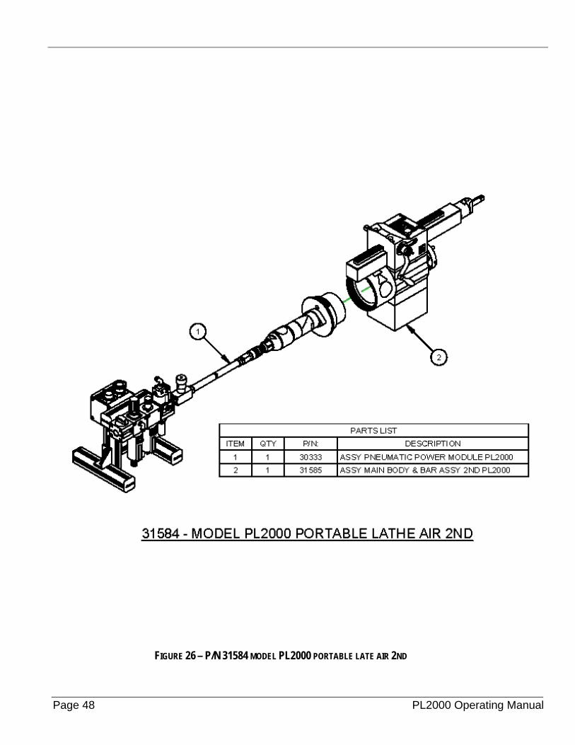
Page 48 PL2000 Operating Manual
FIGURE 26 – P/N 31584 MODEL PL2000 PORTABLE LATE AIR 2ND

P/N 30898, Rev. 6 Page 49
APPENDIX A MSDS

Page 50 PL2000 Operating Manual

P/N 30898, Rev. 6 Page 51

Page 52 PL2000 Operating Manual

P/N 30898, Rev. 6 Page 53

Page 54 PL2000 Operating Manual

P/N 30898, Rev. 6 Page 55

Page 56 PL2000 Operating Manual

P/N 30898, Rev. 6 Page 57

Page 58 PL2000 Operating Manual

P/N 30898, Rev. 6 Page 59

Page 60 PL2000 Operating Manual

P/N 30898, Rev. 6 Page 61

Page 62 PL2000 Operating Manual

P/N 30898, Rev. 6 Page 63

Page 64 PL2000 Operating Manual

P/N 30898, Rev. 6 Page 65

Page 66 PL2000 Operating Manual

P/N 30898, Rev. 6 Page 67

Page 68 PL2000 Operating Manual
P/N 30898, Rev. 6 Page 69

Page 70 PL2000 Operating Manual

P/N 30898, Rev. 6 Page 71

Page 72 PL2000 Operating Manual
This page left intentionally blank.

