climax ff4000 flange facer ff1000 · climax portable machine tools, inc. (hereafter referred to as...
TRANSCRIPT

Climax FF4000 Flange Facer
P/N 32139 May 2019 Revision 2
FF1000
FLANGE FACER OPERATING MANUAL
SERIAL NUMBER RANGE: 11017900 - 15121870
ORIGINAL INSTRUCTIONS
FF1000 Flange Facer shown


P/N 32139, Rev. 2 Page 1
©2019 CLIMAX or its subsidiaries. All rights reserved.
Except as expressly provided herein, no part of this manual may be reproduced, copied, transmitted, disseminated, downloaded, or stored in any storage medium, without the express prior written consent of CLIMAX. CLIMAX hereby grants permission to download a single copy of this manual and of any revision hereto onto an electronic storage medium to be viewed and to print one copy of this manual or any revision hereto, pro- vided that such electronic or printed copy of this manual or revision must contain the complete text of this copyright notice and provided further that any unauthorized commercial distribution of this manual or any revision hereto is prohibited. At CLIMAX, we value your opinion. For comments or questions about this manual or other CLIMAX documentation, please e-mail [email protected]. For comments or questions about CLIMAX products or services, please call CLIMAX or e-mail [email protected]. For quick and accurate service, please provide your representative with the following:
• Your name • Shipping address • Telephone number • Machine model • Serial number (if applicable) • Date of purchase
CLIMAX World Headquarters 2712 East 2nd Street Newberg, Oregon 97132 USA Telephone (worldwide): +1-503-538-2815 Toll-free (North America): 1-800-333-8311 Fax: 503-538-7600
H&S Tool World Headquarters 715 Weber Dr. Wadsworth, OH 44281 USA Telephone: +1-330-336-4550 Fax: 1-330-336-9159 hstool.com
CLIMAX | H&S Tool (UK Headquarters) Unit 7 Castlehill Industrial Estate Bredbury Industrial Park Horsfield Way Stockport SK6 2SU, UK Telephone: +44 (0) 161-406-1720
CLIMAX | H&S Tool (European Headquarters) Am Langen Graben 8 52353 Düren, Germany Telephone: +49 24-219-1770 E-mail: [email protected]
CLIMAX | H&S Tool (Asia Pacific Head- quarters)
316 Tanglin Road #02-01 Singapore 247978 Telephone: +65 9647-2289 Fax: +65 6801-0699
CLIMAX | H&S Tool (Middle East Headquarters)
Warehouse #5, Plot: 369 272 Um Sequim Road Al Quoz 4 PO Box 414 084 Dubai, UAE Telephone: +971 04-321-0328

Page 2 FF1000 Operating Manual
CLIMAX GLOBAL LOCATIONS
P/N 32139, Rev. 2 Page 3
LIMITED WARRANTY CLIMAX Portable Machine Tools, Inc. (hereafter referred to as “CLIMAX”) warrants that all new machines are free from defects in materials and workmanship. This warranty is available to the original purchaser for a period of one year after delivery. If the original purchaser finds any defect in materials or workmanship within the warranty period, the original purchaser should contact its factory representative and return the entire machine, shipping prepaid, to the factory. CLIMAX will, at its option, either repair or replace the defective machine at no charge and will return the machine with shipping prepaid. CLIMAX warrants that all parts are free from defects in materials and workmanship, and that all labor has been performed properly. This warranty is available to the customer purchasing parts or labor for a period of 90 days after delivery of the part or repaired machine or 180 days on used machines and components. If the customer purchasing parts or labor finds any defect in materials or workmanship within the warranty period, the purchaser should contact its factory representative and return the part or repaired machine, shipping pre- paid, to the factory. CLIMAX will, at its option, either repair or replace the defective part and/ or correct any defect in the labor performed, both at no charge, and return the part or repaired machine shipping prepaid. These warranties do not apply to the following:
• Damage after the date of shipment not caused by defects in materials or workmanship • Damage caused by improper or inadequate machine maintenance • Damage caused by unauthorized machine modification or repair • Damage caused by machine abuse • Damage caused by using the machine beyond its rated capacity
All other warranties, express or implied, including without limitation the warranties of merchantability and fitness for a particular purpose are disclaimed and excluded. Terms of sale Be sure to review the terms of sale which appear on the reverse side of your invoice. These terms control and limit your rights with respect to the goods purchased from CLIMAX. About this manual CLIMAX provides the contents of this manual in good faith as a guideline to the operator. CLIMAX cannot guarantee that the information contained in this manual is correct for applications other than the application described in this manual. Product specifications are subject to change without notice.
Page 4 FF1000 Operating Manual
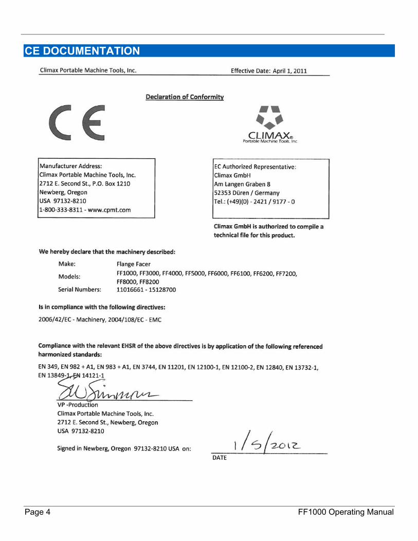
CE DOCUMENTATION
P/N 32139, Rev. 2 Page 5
Introduction The information in this manual is up to date at time of printing. Because Climax is committed to continued product improvement, the machine you receive may be slightly different than the one described here.
About this manual
WARNING Moving machine parts can seriously injure untrained operators. Understand all instructions before operating this machine.
This manual describes how to use your Model FF1000 Flange Facer (the ModuLATHE). Every part meets Climax Portable Machining & Welding Systems’ strict quality standards. For maximum safety and performance, read the entire instruction manual before operating the flange facer.
Typical application of the FF1000 flange facer The FF1000 Flange Facer (ModuLATHE), featuring a power unit and facing head attachment, can re-face flanges up to 12" (304.8 mm) in diameter and cut O-ring grooves. The modular design and setup options allow you to be creative in solving difficult maintenance problems. Please follow the operating manual and maintain the integrity of the machine. For your own safety, do not modify this machine in any way.
Check the machine when you receive it Inspect the machine for shipping damage. Be sure you received the parts listed on the invoice. Contact Climax immediately if there are any errors or questions about this machine.

Page 6 FF1000 Operating Manual
Labeling Guidelines The purpose of product safety signs and labels is to increase the level of awareness to possible dangers. Safety Alert Symbols indicate DANGER, WARNING or CAUTION. These symbols may be used in conjunction with other symbols or pictographs. Failure to obey safety warnings can result in serious injury. Always follow safety precautions to reduce the risk of hazards and serious injury.
DANGER Indicates a hazardous situation that could be fatal or cause serious injury.
WARNING Indicates a potentially hazardous situation that could be fatal or cause serious injury.
CAUTION Indicates a potentially hazardous situation that could result in minor to moderate injury, damage to the machine or interruption of an important process.
IMPORTANT Provides critical information for the completion of a task. There is no associated hazard to people or the machine.
NOTE Provides important information regarding the machine.
P/N 32139, Rev. 2 Page 7
General Safety Guidelines The primary challenge for most on-site maintenance is that repairs are often done under difficult conditions. Portable Machining & Welding Systems leads the way in promoting the safe use of portable machine tools. Safety is a joint effort. As the operator of this machine, you are expected to do your part by closely examining the job site and following the operating procedures outlined in this manual, your own company rules, and local regulations.
WARNING For maximum safety and performance, read and understand this entire manual and all other related safety instructions before using this equipment. Failure to follow the instructions and guidelines in this manual could cause personal injury, fatalities and property damage.
QUALIFIED PERSONNEL
Before operating this machine, you must receive training specific to this machine from a qualified trainer. Do not operate the machine If you are not familiar with the proper and safe operation.
OBEY WARNING LABELS
Obey all warning labels. Failure to follow instructions or heed warnings could result in injury, or even be fatal. Proper care is your responsibility. Contact Climax immediately for replacement manuals or safety decals.
INTENDED USE
Use this machine according to the instructions in this operating manual. Do not use this machine for any purpose other than its intended use as described in this manual.
STAY CLEAR OF MOVING PARTS
Keep clear of the machine during operation. Never lean toward or reach into the machine to remove chips or to adjust the machine while it is running.
ELECTRICAL HAZARDS
Electrically ground all machines. Be sure the electric power source matches the requirements of the machine and complies with appropriate electrical codes. Do not operate an electric
machine in damp or explosive conditions. It may cause an explosion or expose the operator to electric shock.
ROTATING MACHINERY
Rotating machinery can seriously injure an operator. Lock out all power sources before you interact with the machine.
KEEP YOUR WORK AREA CLEAN AND TIDY
Keep all cords and hoses away from moving parts during operation. Do not clutter the area around the machine.
SECURE LOOSE CLOTHING AND LONG HAIR
Rotating machinery can cause serious injuries. Do not wear loose fitting clothing or jewelry. Tie back long hair or wear a hat.
HAZARDOUS ENVIRONMENTS
Do not use the machine near explosive chemicals, toxic fumes, inappropriate radiation hazards or other hazardous environments.
FLYING CHIPS
Flying metal chips can cut or burn. Do not remove chips until after the machine has been locked out, all power sources are off and the machine has stopped.
Page 8 FF1000 Operating Manual
General safety practices All aspects of the machine have been designed with safety in mind. Rotating parts are shielded by machine components or by the workpiece. PERSONAL PROTECTIVE EQUIPMENT
Eye and hearing protection must be worn while using the machine. These safety items do not impose constraints to the safe operation of the machine.
OPERATING CONDITIONS
Do not operate the machine if it is not mounted to the workpiece as described in this manual.
TOOLING
The machine is provided with all the tools for the setup and operation of the machine.
LIFTING
Most of the machine components are heavy and must be moved or lifted with approved rigging and practices. Climax accepts no responsibility for the selection of lifting equipment.
Always follow your plant’s procedures for lifting heavy objects. Do not lift heavy objects by yourself as serious injury can result.
CUTTING FLUIDS
There are no cutting or cooling fluids used with this machine.
CONTROLS
The machine controls are designed to withstand the rigors of normal use and external factors. The on-off switches are clearly visible and identifiable. If a compressed air supply failure occurs, be sure to turn off the on-off valve before leaving the machine.
DANGER ZONE
The operator and other persons can be anywhere in the vicinity of the machine. The operator must ensure there are no other persons in danger from the machine.
APPROPRIATE LIGHTING
Ensure your work area is well lit.
METAL FRAGMENT HAZARD
The machine produces metallic fragments during normal operation. You should wear eye protection and gloves at all times when working with the machine.
RADIATION HAZARDS
There are no systems or components on this machine that are capable of producing hazardous EMC, UV or other radiation hazards. The machine does not use lasers nor does it create hazardous materials such as gasses or dust.
ADJUSTMENTS AND MAINTENANCE
All adjustments, lubrication and maintenance should be done with the machine stopped, and locked out from all power sources. The shut-off valve should be locked and tagged out before any maintenance occurs.
WARNING LABELS
Warning labels are already attached to your machine. Contact Climax immediately if replacements are required.
MAINTENANCE
Be sure the machine components are free of debris and properly lubricated prior to use.
P/N 32139, Rev. 2 Page 9
Machine specific Safety Information
Audible noise levels
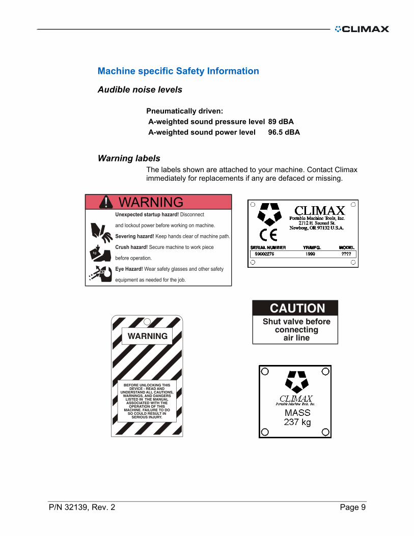
Pneumatically driven: A-weighted sound pressure level 89 dBA A-weighted sound power level 96.5 dBA
Warning labels The labels shown are attached to your machine. Contact Climax immediately for replacements if any are defaced or missing.
WARNING

Page 10 FF1000 Operating Manual
Risk assessment and hazard mitigation Machine Tools are specifically designed to perform precise material-removal operations. Stationary Machine Tools include lathes and milling machines and are typically found in a machine shop. They are mounted in a fixed location during operation and are considered to be a complete, self-contained machine. Stationary Machine Tools achieve the rigidity needed to accomplish material-removal operations from the structure that is an integral part of the machine tool. In contrast, Portable Machine Tools are designed for on-site machining applications. They typically attach directly to the workpiece itself, or to an adjacent structure, and achieve their rigidity from the structure to which it is attached. The design intent is that the Portable Machine Tool and the structure attached to it become one complete machine during the material-removal process. To achieve the intended results and to promote safety, the operator must understand and follow the design intent, set-up, and operation practices that are unique to Portable Machine Tools. The operator must perform an overall review and on-site risk assessment of the intended application. Due to the unique nature of portable machining applications, identifying one or more hazards that must be addressed is typical. When performing the on-site risk assessment, it is important to consider the Portable Machine Tool and the workpiece as a whole.
P/N 32139, Rev. 2 Page 11
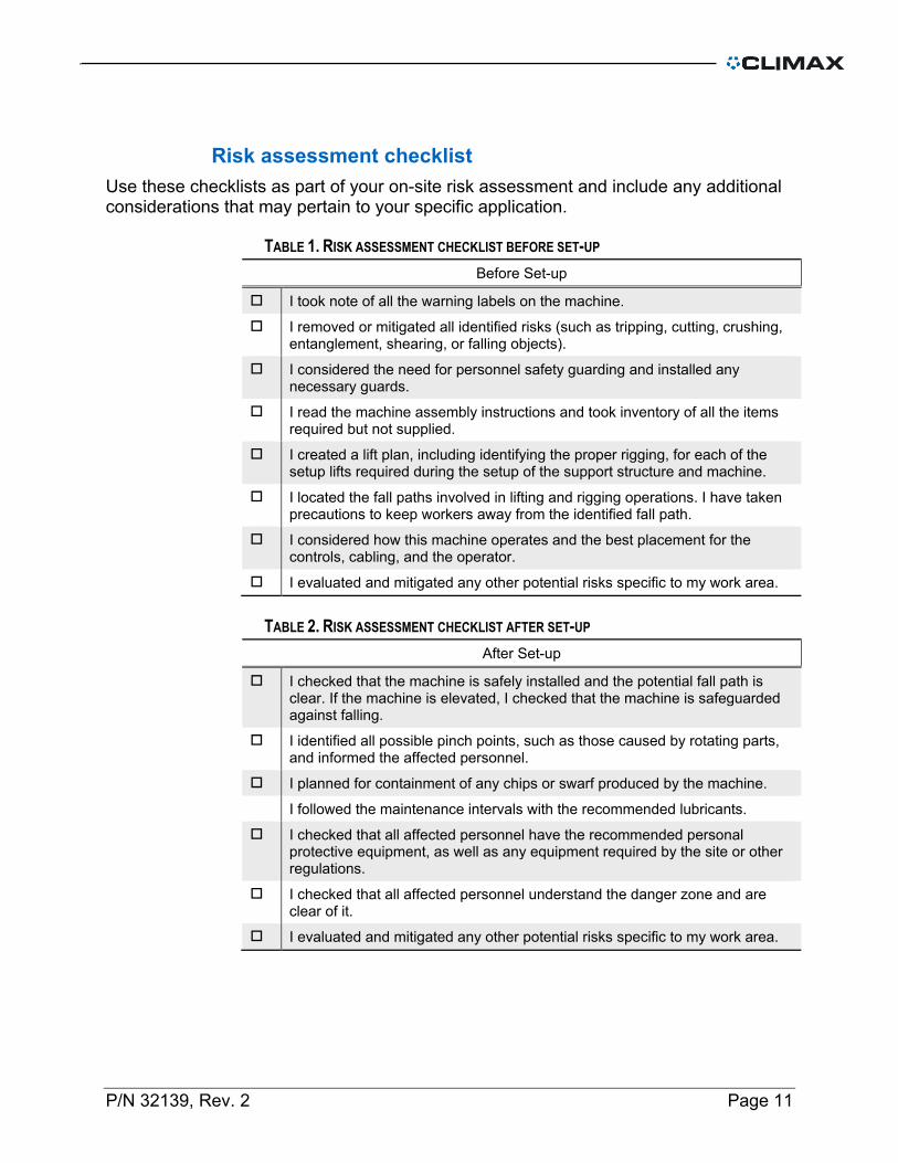
Risk assessment checklist Use these checklists as part of your on-site risk assessment and include any additional considerations that may pertain to your specific application.
TABLE 1. RISK ASSESSMENT CHECKLIST BEFORE SET-UP Before Set-up
I took note of all the warning labels on the machine.
I removed or mitigated all identified risks (such as tripping, cutting, crushing, entanglement, shearing, or falling objects).
I considered the need for personnel safety guarding and installed any necessary guards.
I read the machine assembly instructions and took inventory of all the items required but not supplied.
I created a lift plan, including identifying the proper rigging, for each of the setup lifts required during the setup of the support structure and machine.
I located the fall paths involved in lifting and rigging operations. I have taken precautions to keep workers away from the identified fall path.
I considered how this machine operates and the best placement for the controls, cabling, and the operator.
I evaluated and mitigated any other potential risks specific to my work area.
TABLE 2. RISK ASSESSMENT CHECKLIST AFTER SET-UP After Set-up
I checked that the machine is safely installed and the potential fall path is clear. If the machine is elevated, I checked that the machine is safeguarded against falling.
I identified all possible pinch points, such as those caused by rotating parts, and informed the affected personnel.
I planned for containment of any chips or swarf produced by the machine.
I followed the maintenance intervals with the recommended lubricants. I checked that all affected personnel have the recommended personal
protective equipment, as well as any equipment required by the site or other regulations.
I checked that all affected personnel understand the danger zone and are clear of it.
I evaluated and mitigated any other potential risks specific to my work area.
Page 12 FF1000 Operating Manual
Description The FF1000 Flange Facer is intended to perform facing operations. Modular construction allows the machine to perform a variety of operations.
The machine consists of:
Power module: Drive box assembly Quill support assembly Vertical adjustment leadscrew assembly Air motor assembly Pneumatic conditioning unit Tool kit
Flange facing module: Facing head gearbox assembly Slide & tool head assembly Mounting bell assembly Facing head tool kit
Optional assemblies: Power feed module Exploded-view drawings and part lists are at the end of this manual.
P/N 32139, Rev. 2 Page 13
Setup Preparation
WARNING To avoid serious bodily injury, turn off and lock out the motor before setting up or adjusting the machine.
1. Mount the power module to the mounting bell. 2. Tighten the mounting screws. 3. Mount the feed cam onto the end of the quill housing. 4. Carefully align the setscrew holes with the slots on the quill
housing. 5. Attach the facing head assembly to the end of the spindle,
using the screws provided. 6. Measure the diameter of the flange. 7. Insert the setup fingers into the mounting bell. 8. Adjust the setup fingers so they will catch on the edge of the
flange and support the machine during setup.
Setup
WARNING To avoid serious bodily injury from rotating machinery, turn off and lock out the machine before setup.
1. Set the machine on the flange. The setup fingers will support
the machine. 2. Center the machine to within .0625 by adjusting the clamping
screws. Because the inside of the mounting bell is machined, it can be used to determine the center.
3. Completely tighten the clamping screws.
Page 14 FF1000 Operating Manual
To level the machine: 1. Attach the dial indicator to the tool carrier
WARNING To avoid serious bodily injury from rotating machinery, use the manual rotation tool to level the machine.
2. Remove the motor from the drive box. 3. Insert the manual rotation tool into the drive box. 4. Swing the dial indicator by turning the rotation tool with a
3/4" box-end wrench (in power module tool kit). 5. Adjust the leveling setscrews in the base of the quill
housing until the dial indicator indicates a level surface. 6. Tighten the clamping screws.
To accurately center the machine: 1. Slightly loosen the level clamping screws. 2. With the indicator on a diameter, adjust the centering
screw in the centering/leveling plate until centered. 3. Verify the adjustment and correct if needed. 2. Remove the setup fingers and indicator.
P/N 32139, Rev. 2 Page 15
Tool setup 1. Loosen the quill support clamping screws. 2. Turn the vertical adjustment leadscrew counterclockwise to
raise the tool bit carrier.
NOTE Be careful not to raise the facing head too high. The feed cam will be forced off and you will have to set the machine up again.
3. Insert the tool bit into the tool carrier. 4. Position the tool bit for clockwise rotation (when looking down
from the top of the power head).
Air power connection
WARNING Rotating machinery can seriously injure the operator. Securely mount the machine to the work piece before connecting the air supply line.
Motor connection If the air motor is to be mounted to the drive box: 1. Insert the drive key into the air motor output shaft keyway. 2. Align the air motor output shaft with the worm carrier shaft
inside the drive box. 3. Insert the air motor shaft into the worm carrier shaft until the
motor flange fits snugly against the drive box. 4. Tighten the motor mounting screws. Climax strongly
recommends using the air filter and lubricator supplied with the machine. The lubricator should be set to deliver oil air at a rate of 2-4 drops per minute.
CAUTION To avoid air motor damage and increase air motor performance, use the filter and lubricator provided.
Page 16 FF1000 Operating Manual
Starting and stopping U.S. style machines The U.S. style flange facer is equipped with needle valves and lockout valves.
NOTE Use non-restrictive fittings for air connections.
To start the machine: 1. Push the lever (on the lockout valve) until the word CLOSED
and the lockout can be seen from the bottom of the valve. Be sure the lever is pushed all the way in.
2. Turn the needle valve clockwise all the way. You will not see any colored bands when the valve is completely closed.
3. Connect the pneumatic conditioning unit and air supply line. 4. Press the lever (on the lockout valve) until the word OPEN can
be seen from the top of the valve. Be sure the lever is pushed all the way in.
5. Slowly turn the needle valve counterclockwise until the machine is rotating at the desired speed. The more colored bands you see, the faster the machine rotation.
WARNING In case of emergency, push the lockout valve lever closed.
To stop the machine: 1. Turn the air supply off all the way. 2. Push the lockout valve lever until the word CLOSED and the
lockout can be seen from the bottom of the valve. Be sure the lever is pushed all the way in.
3. Lock out the machine. 4. Disconnect the air supply line.
P/N 32139, Rev. 2 Page 17
Starting and stopping CE compliant machines
NOTE Use non-restrictive fittings for air connections.
To start the machine: 1. Be sure the emergency valve assembly is connected to the air
motor. 2. Turn the air supply valve OFF all the way. 3. Connect the pneumatic conditioning unit and air supply line to
the valve assembly. 4. Pull the spring plunger out to let air into the valve assembly. 5. Slowly turn the air supply valve ON until the machine is
rotating at the desired speed.
WARNING In case of emergency, push the spring plunger closed.
To stop the machine: 1. Push the spring plunger to close the valve assembly. 2. Close the air supply valve all the way. 3. Lock out the machine. 4. Disconnect the air supply line.
Page 18 FF1000 Operating Manual
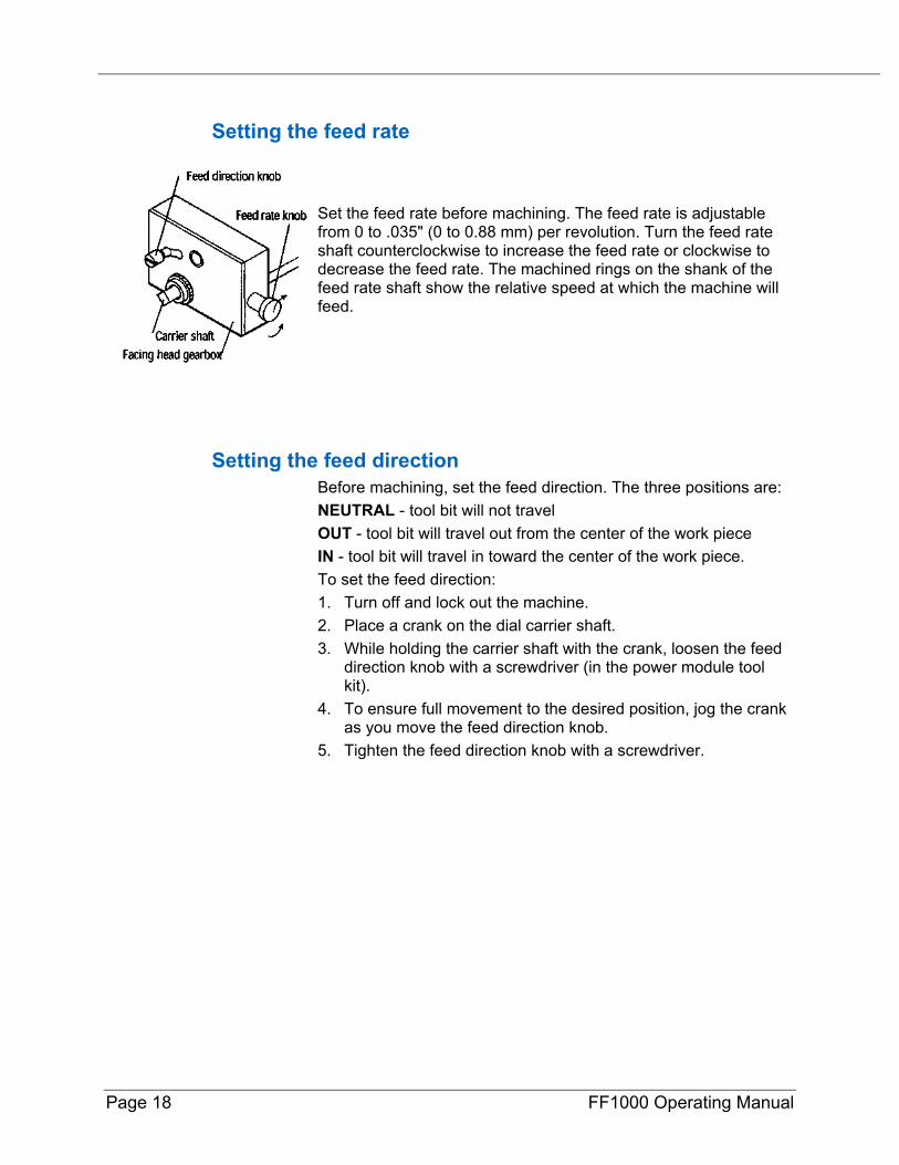
Setting the feed rate
Set the feed rate before machining. The feed rate is adjustable from 0 to .035" (0 to 0.88 mm) per revolution. Turn the feed rate shaft counterclockwise to increase the feed rate or clockwise to decrease the feed rate. The machined rings on the shank of the feed rate shaft show the relative speed at which the machine will feed.
Setting the feed direction Before machining, set the feed direction. The three positions are: NEUTRAL - tool bit will not travel OUT - tool bit will travel out from the center of the work piece IN - tool bit will travel in toward the center of the work piece. To set the feed direction: 1. Turn off and lock out the machine. 2. Place a crank on the dial carrier shaft. 3. While holding the carrier shaft with the crank, loosen the feed
direction knob with a screwdriver (in the power module tool kit).
4. To ensure full movement to the desired position, jog the crank as you move the feed direction knob.
5. Tighten the feed direction knob with a screwdriver.
P/N 32139, Rev. 2 Page 19
Operation
WARNING Wear ear and eye protection while operating the machine.
1. Turn off and lock out the machine. 2. Be sure the incoming air valve system is closed.
WARNING Rotating machinery can seriously injure the operator. Stop and lock out the machine before connecting the air supply line.
3. Set the feed direction to NEUTRAL. 4. Check that the tool bit is facing the correct direction. 5. Manually crank the dial carrier shaft until the tool bit is over,
but not touching, the flange. 6. Close the mounting bell safety screens. Be sure they are
latched. 7. Unlock the incoming air valve. 8. Slowly turn the air valve supply ON until the machine begins
rotating
WARNING In case of emergency, push the lockout valve lever closed.
9. Slowly crank the vertical feed shaft assembly clockwise to
lower the tool bit until it just touches the face of the flange. 10. Set the dial to zero. 11. Move the tool bit up off the flange by cranking the vertical feed
shaft assembly counterclockwise. 12. Stop the machine by turning the valve air supply OFF all the
way. 13. Shut the incoming air valve. 14. Disconnect the incoming air hose.
Page 20 FF1000 Operating Manual
15. Open the mounting bell safety screen. 16. Manually crank the dial carrier shaft to move the tool bit out
past the edge of the flange. 17. Set the tool bit to the desired cutting depth by turning the dial.
"0" will be at the face of the flange if you set the dial to zero in the previous steps.
NOTE The dial is marked in .001" (.0254 mm) increments. One full turn equals .020" (.508 mm).
18. Tighten the quill clamping screws. 19. Set the feed direction to face OUT or IN. 20. Set the machine feed rate. 21. Close the mounting bell safety screens. Be sure they are
latched. 22. Reconnect the pneumatic conditioning unit and the air supply
line. 23. Open the incoming air valve. 24. Slowly turn the air valve until the machine is rotating at the
desired speed. 25. Allow the machine to face the flange completely.
CAUTION The facing head slide does not have a built-in stop mechanism. When facing out from the center, be sure to stop the facing head after machining to keep the facing head tool carrier from traveling off the end of the slide.
26. Stop the machine by turning the valve air supply OFF all the
way. 27. Shut the incoming air valve. Lock out the machine. 28. Reset the feed direction to NEUTRAL. 29. Retract the tool bit by manually turning the vertical feed shaft
assembly counterclockwise. 30. Repeat these steps as necessary.
P/N 32139, Rev. 2 Page 21
Disassembly
WARNING To avoid serious personal injury from rotating machinery, turn off and disconnect the power supply before disassembling the machine.
1. Turn the air valve OFF all the way. 2. Shut the incoming air valve. 3. Lock out the machine. 4. Disconnect the air supply line. 5. Set the feed direction to NEUTRAL. 6. Move the tool bit up off the flange by turning the vertical feed
shaft assembly counterclockwise. 7. Loosen the tool bit set screws. 8. Remove the tool bit. 9. Loosen the clamping screws. 10. Pull the machine from the flange.
Page 22 FF1000 Operating Manual
Optional Accessories Power feed module
The electric power feed module automatically feeds the machine axially.
Power feed setup 1. Place the motor coupler onto the vertical feed shaft assembly. 2. Tighten the setscrews. 3. Mount the bracket onto the quill support using the two socket-
head cap screws.
NOTE If the bracket is being mounted to an older machine, tap two mating bracket holes 1/4-20 by at least 3/8" deep in the quill support.
4. Mount the electric motor to the bracket. 5. Connect the electric motor to the speed control with the motor
control cord.
Power feed operation 1. Be sure the quill clamping screws are snug enough to cause
tension on the quill without binding.
CAUTION To avoid damaging the machine, do not loosen the quill clamping screws at any time during or between machining operations.
2. Close the incoming air valve. Lock out the machine. 3. Turn the air supply valve OFF all the way. 4. Route the air supply line through the pneumatic conditioning
unit.
P/N 32139, Rev. 2 Page 23
NOTE Climax strongly recommends using the filter and lubricator supplied with the machine. Set the lubricator to deliver oil at a rate of 2-4 drops per minute.
CAUTION To avoid air motor damage and increase air motor performance, use the filter and lubricator provided.
5. Retract the tool bit slightly. 6. Position the tool head at the desired depth. 7. Turn the direction lever on the speed control to BRAKE. 8. Turn the speed adjustment knob on the speed control
counterclockwise to “0”. 9. Turn off the power switch. 10. Be sure all electrical components are properly connected. 11. Plug in the speed control. 12. Set the power switch on the speed control to either LO or HI.
Maximum torque is only reached in LO. 13. Turn the speed control direction lever to the desired setting. 14. Machine the work piece.
Page 24 FF1000 Operating Manual
Maintenance _______________________________________ Recommended lubricants LUBRICANT BRAND WHERE USED Gear grease UNOBA EP #2 Gear box gears, thrust bearings Light oil WD-40 Unpainted surfaces Cutting oil UNOCAL KOOLKUT Tool bits, work piece Lubricating oil Marvel Air Tool Oil Lubricator oil cup Lubricant Bostik NEVER-SEEZ Quill housing Way oil Mobil VACTRA Heavy-Medium Way Oil Dovetail ways
CAUTION To avoid damaging the machine, use recommended lubricants.
.
Drive box assembly Periodically check all drive box seals. Replace worn or cracked seals. Remove the gearbox lid and grease the worm and worm gear every 100 hours.
Quill support assembly Grease the vertical feed shaft assembly every 100 hours.
Vertical adjustment leadscrew assembly Leadscrew assembly parts are lubricated for life.
Air motor assembly and pneumatic conditioning unit To protect the air motor: Route the air supply through the lubricator and air filter. Use non-restrictive air lines and fittings. Check the air system periodically to be sure the air pressure is
90 psi (620 kPa). Adjust the air motor speed by adjusting the needle valve.
CAUTION To avoid damaging the motor, do not adjust the motor speed by changing the in-line air pressure from 90 psi (620 kPa).
P/N 32139, Rev. 2 Page 25
Fill the lubricator oil cup with air oil before using the machine. Use high-quality oil with rust inhibitors and emulsifiers such as Marvel Air Tool Oil. Set the lubricator to deliver oil the air at a rate of 2-4 drops per minute.
Drain the air filter before and after machining.
CAUTION To avoid damaging the air motor and voiding the warranty, route the incoming air through the air filter and lubricator.
Facing head gearbox assembly After the machine has stopped, clean chips from the feed direction slot. The gearbox is sealed and lubricated for life.
Facing head slide assembly Lightly oil the leadscrew periodically with light oil. DO NOT GREASE THE LEADSCREW!
Mounting bell assembly Mounting bell parts are lubricated for life.
Tool bit If using HSS tool bits, be sure that they have the proper geometry. Grind the tool bits as needed during operation. If using carbide tools; replace the inserts and chip breakers as needed during operation. For tool bit replacement information, contact your Climax factory representative by calling Climax toll free at 1-800-333-8311.
Power feed module The power feed module needs no maintenance if used according to the instructions.

Page 26 FF1000 Operating Manual
Storage Proper storage of the machine will prevent undue deterioration or damage. Before storing the machine, clean it with solvent to remove grease, metal chips, and moisture. Spray the machine with a moisture-protective material (WD-40 for short-term storage, Cosmoline for long-term storage) to prevent rusting. Store the machine in the containers provided. Place desiccant bags or vapor wrap around the machine to absorb moisture.
To replace a storage container, order Part No. 18475 (large - holds 12" mounting bell) or Part No. 10860 (small).
P/N 32139, Rev. 2 Page 27
Spare Parts
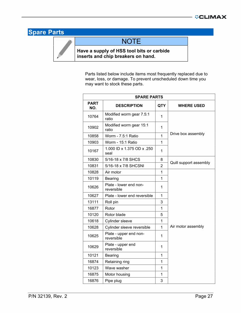
NOTE Have a supply of HSS tool bits or carbide inserts and chip breakers on hand.
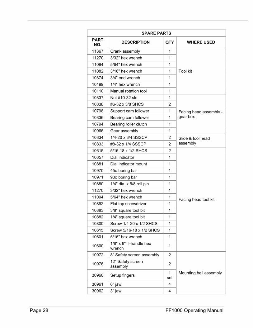
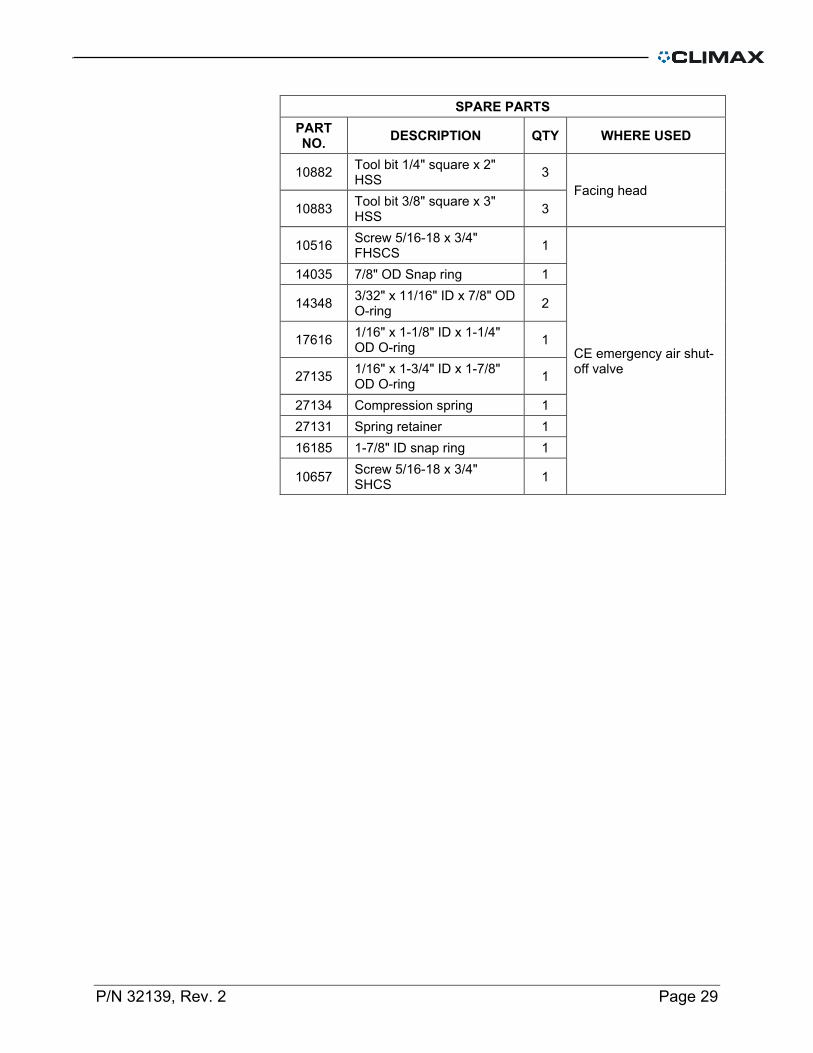
Parts listed below include items most frequently replaced due to wear, loss, or damage. To prevent unscheduled down time you may want to stock these parts.
SPARE PARTS PART NO. DESCRIPTION QTY WHERE USED
10764 Modified worm gear 7.5:1 ratio 1
Drive box assembly 10902 Modified worm gear 15:1
ratio 1
10858 Worm - 7.5:1 Ratio 1 10903 Worm - 15:1 Ratio 1
10167 1.000 ID x 1.375 OD x .250 seal 1
10830 5/16-18 x 7/8 SHCS 8 Quill support assembly
10831 5/16-18 x 7/8 SHCSNI 2 10828 Air motor 1
Air motor assembly
10119 Bearing 1
10626 Plate - lower end non-reversible 1
10627 Plate - lower end reversible 1 13111 Roll pin 3 16877 Rotor 1 10120 Rotor blade 5 10618 Cylinder sleeve 1 10628 Cylinder sleeve reversible 1
10625 Plate - upper end non-reversible 1
10629 Plate - upper end reversible 1
10121 Bearing 1 16874 Retaining ring 1 10123 Wave washer 1 16875 Motor housing 1 16876 Pipe plug 3
Page 28 FF1000 Operating Manual
SPARE PARTS PART NO. DESCRIPTION QTY WHERE USED
11367 Crank assembly 1
Tool kit
11270 3/32" hex wrench 1 11094 5/64" hex wrench 1 11082 3/16" hex wrench 1 10874 3/4" end wrench 1 10199 1/4" hex wrench 1 10110 Manual rotation tool 1 10837 Nut #10-32 std 1
Facing head assembly - gear box
10838 #6-32 x 3/8 SHCS 2 10798 Support cam follower 1 10836 Bearing cam follower 1 10794 Bearing roller clutch 1 10966 Gear assembly 1 10834 1/4-20 x 3/4 SSSCP 2 Slide & tool head
assembly 10833 #8-32 x 1/4 SSSCP 2 10615 5/16-18 x 1/2 SHCS 2
Facing head tool kit
10857 Dial indicator 1 10881 Dial indicator mount 1 10970 45o boring bar 1 10971 90o boring bar 1 10880 1/4" dia. x 5/8 roll pin 1 11270 3/32" hex wrench 1 11094 5/64" hex wrench 1 10892 Flat top screwdriver 1 10883 3/8" square tool bit 1 10882 1/4" square tool bit 1 10800 Screw 1/4-20 x 1/2 SHCS 1 10615 Screw 5/16-18 x 1/2 SHCS 1 10601 5/16" hex wrench 1
10600 1/8" x 6" T-handle hex wrench 1
10972 8" Safety screen assembly 2
Mounting bell assembly
10976 12" Safety screen assembly 2
30960 Setup fingers 1 set
30961 6" jaw 4 30962 3" jaw 4
P/N 32139, Rev. 2 Page 29
SPARE PARTS PART NO. DESCRIPTION QTY WHERE USED
10882 Tool bit 1/4" square x 2" HSS 3
Facing head 10883 Tool bit 3/8" square x 3"
HSS 3
10516 Screw 5/16-18 x 3/4" FHSCS 1
CE emergency air shut-off valve
14035 7/8" OD Snap ring 1
14348 3/32" x 11/16" ID x 7/8" OD O-ring 2
17616 1/16" x 1-1/8" ID x 1-1/4" OD O-ring 1
27135 1/16" x 1-3/4" ID x 1-7/8" OD O-ring 1
27134 Compression spring 1 27131 Spring retainer 1 16185 1-7/8" ID snap ring 1
10657 Screw 5/16-18 x 3/4" SHCS 1

Page 30 FF1000 Operating Manual
Exploded Views & Parts The following diagrams and parts lists are for your reference purposes only. The machine Limited Warranty is void if the machine has been tampered with by anyone who has not been authorized in writing by Portable Machining & Welding Systems to perform service on the machine.
P/N 32139, Rev. 2 Page 31
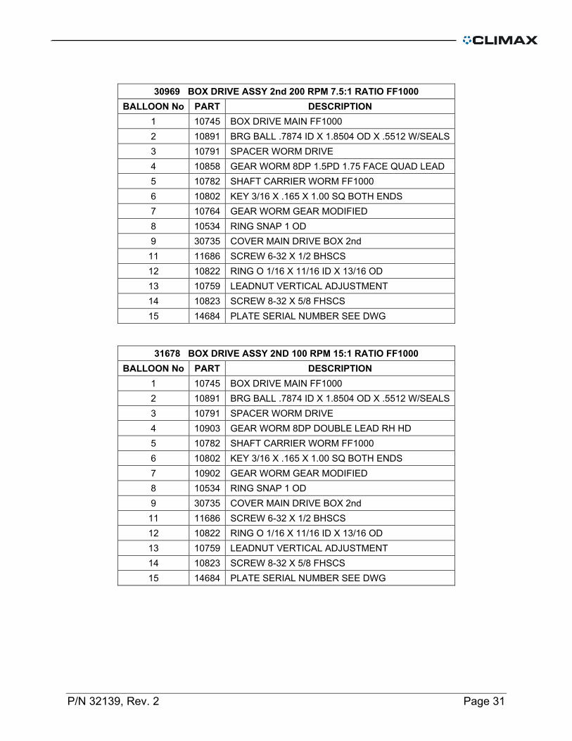
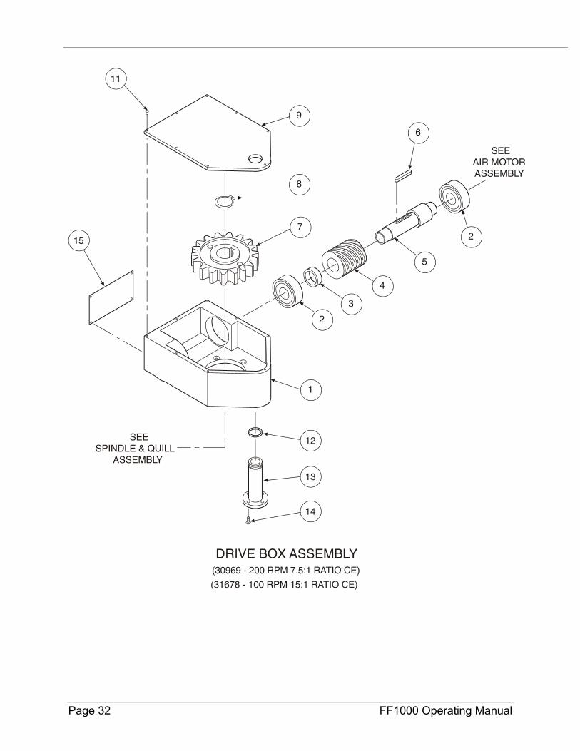
30969 BOX DRIVE ASSY 2nd 200 RPM 7.5:1 RATIO FF1000 BALLOON No PART DESCRIPTION
1 10745 BOX DRIVE MAIN FF1000 2 10891 BRG BALL .7874 ID X 1.8504 OD X .5512 W/SEALS 3 10791 SPACER WORM DRIVE 4 10858 GEAR WORM 8DP 1.5PD 1.75 FACE QUAD LEAD 5 10782 SHAFT CARRIER WORM FF1000 6 10802 KEY 3/16 X .165 X 1.00 SQ BOTH ENDS 7 10764 GEAR WORM GEAR MODIFIED 8 10534 RING SNAP 1 OD 9 30735 COVER MAIN DRIVE BOX 2nd 11 11686 SCREW 6-32 X 1/2 BHSCS 12 10822 RING O 1/16 X 11/16 ID X 13/16 OD 13 10759 LEADNUT VERTICAL ADJUSTMENT 14 10823 SCREW 8-32 X 5/8 FHSCS 15 14684 PLATE SERIAL NUMBER SEE DWG
31678 BOX DRIVE ASSY 2ND 100 RPM 15:1 RATIO FF1000 BALLOON No PART DESCRIPTION
1 10745 BOX DRIVE MAIN FF1000 2 10891 BRG BALL .7874 ID X 1.8504 OD X .5512 W/SEALS 3 10791 SPACER WORM DRIVE 4 10903 GEAR WORM 8DP DOUBLE LEAD RH HD 5 10782 SHAFT CARRIER WORM FF1000 6 10802 KEY 3/16 X .165 X 1.00 SQ BOTH ENDS 7 10902 GEAR WORM GEAR MODIFIED 8 10534 RING SNAP 1 OD 9 30735 COVER MAIN DRIVE BOX 2nd 11 11686 SCREW 6-32 X 1/2 BHSCS 12 10822 RING O 1/16 X 11/16 ID X 13/16 OD 13 10759 LEADNUT VERTICAL ADJUSTMENT 14 10823 SCREW 8-32 X 5/8 FHSCS 15 14684 PLATE SERIAL NUMBER SEE DWG
Page 32 FF1000 Operating Manual
P/N 32139, Rev. 2 Page 33
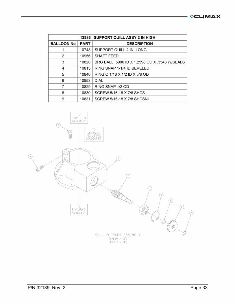
13886 SUPPORT QUILL ASSY 2 IN HIGH BALLOON No PART DESCRIPTION
1 10748 SUPPORT QUILL 2 IN. LONG 2 10956 SHAFT FEED 3 10820 BRG BALL .5906 ID X 1.2598 OD X .3543 W/SEALS 4 10813 RING SNAP 1-1/4 ID BEVELED 5 10840 RING O 1/16 X 1/2 ID X 5/8 OD 6 10853 DIAL 7 10829 RING SNAP 1/2 OD 8 10830 SCREW 5/16-18 X 7/8 SHCS 9 10831 SCREW 5/16-18 X 7/8 SHCSNI
Page 34 FF1000 Operating Manual
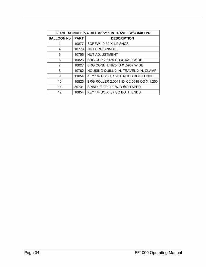
30730 SPINDLE & QUILL ASSY 1 IN TRAVEL W/O #40 TPR BALLOON No PART DESCRIPTION
1 10877 SCREW 10-32 X 1/2 SHCS 4 10779 NUT BRG SPINDLE 5 10755 NUT ADJUSTMENT 6 10826 BRG CUP 2.3125 OD X .4219 WIDE 7 10827 BRG CONE 1.1875 ID X .5937 WIDE 8 10762 HOUSING QUILL 2 IN. TRAVEL 2 IN. CLAMP 9 11054 KEY 1/4 X 3/8 X 1.20 RADIUS BOTH ENDS 10 10825 BRG ROLLER 2.0011 ID X 2.5619 OD X 1.250 11 30731 SPINDLE FF1000 W/O #40 TAPER 12 10854 KEY 1/4 SQ X .37 SQ BOTH ENDS
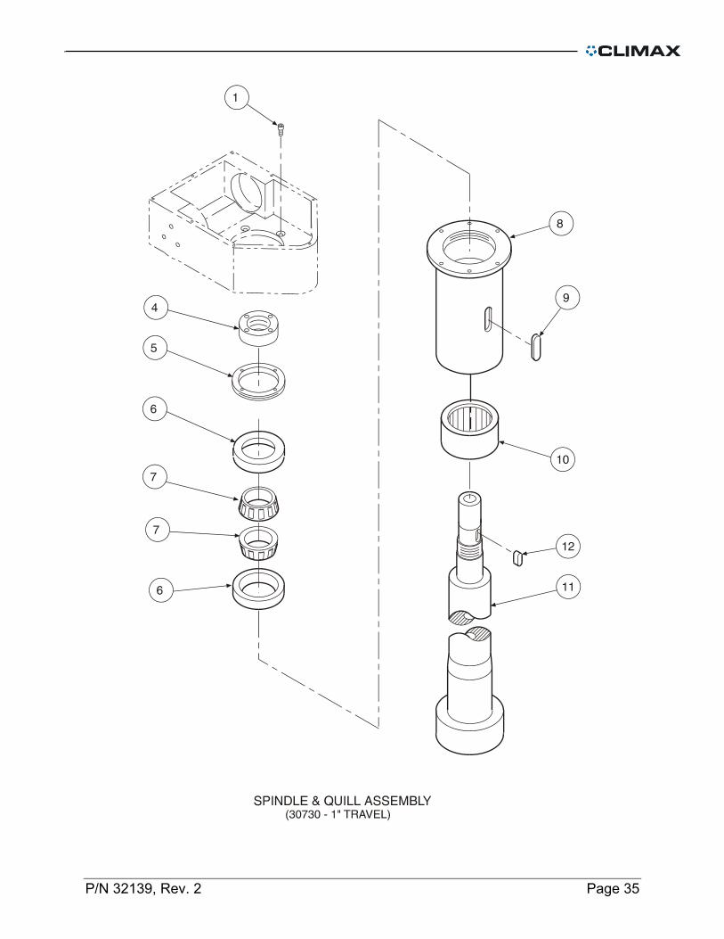
P/N 32139, Rev. 2 Page 35

Page 36 FF1000 Operating Manual

P/N 32139, Rev. 2 Page 37
14389 LEADSCREW VERT ADJUSTMENT 3/4 IN. TRAVEL BALLOON No PART DESCRIPTION
1 10808 BRG BALL .3937 ID X 1.1811 OD X .3543 2 10960 CARRIER ASSY 3/4 IN. TRAVEL 2 IN. CLAMP 3 10807 BRG BALL .7874 ID X 1.6535 OD X .4724 W/SEALS 4 17857 RING SNAP INTERNAL 1.653 BORE (42 mm)
12983 MOTOR AIR ASSY STANLEY MODULATHE BALLOON No PART DESCRIPTION
1 10805 FLANGE MOTOR MODLTH 2 10431 SCREW 5/16-18 X 1 SHCS 3 10828 MOTOR AIR STANLEY 1600 RPM FS 820 RPM LS 4 10803 KEY 3/16 X .135 X 1.00 SQ BOTH ENDS 6 12918 FTG NIPPLE 3/8 NPTM X 1/2 NPTM 7 22530 VALVE NEEDLE ASSY W/LOCKOUT 1/2 IN
NOT SHOWN 22546 LABEL AIR MOTOR
Page 38 FF1000 Operating Manual
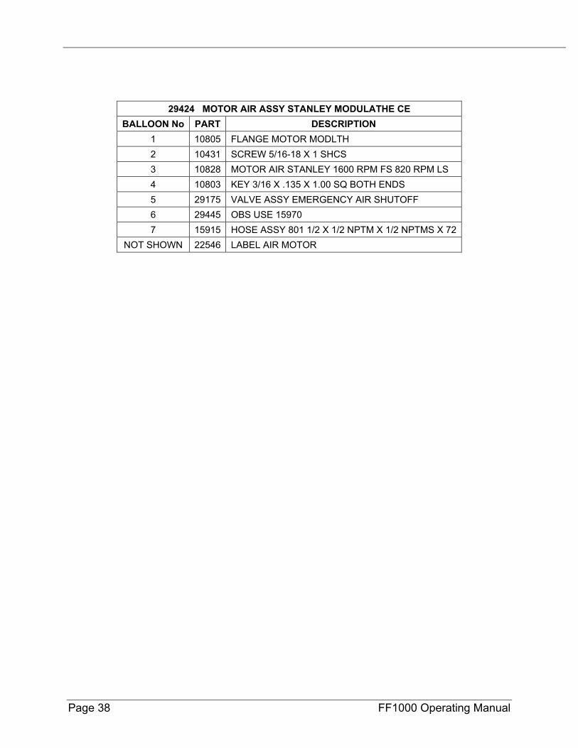
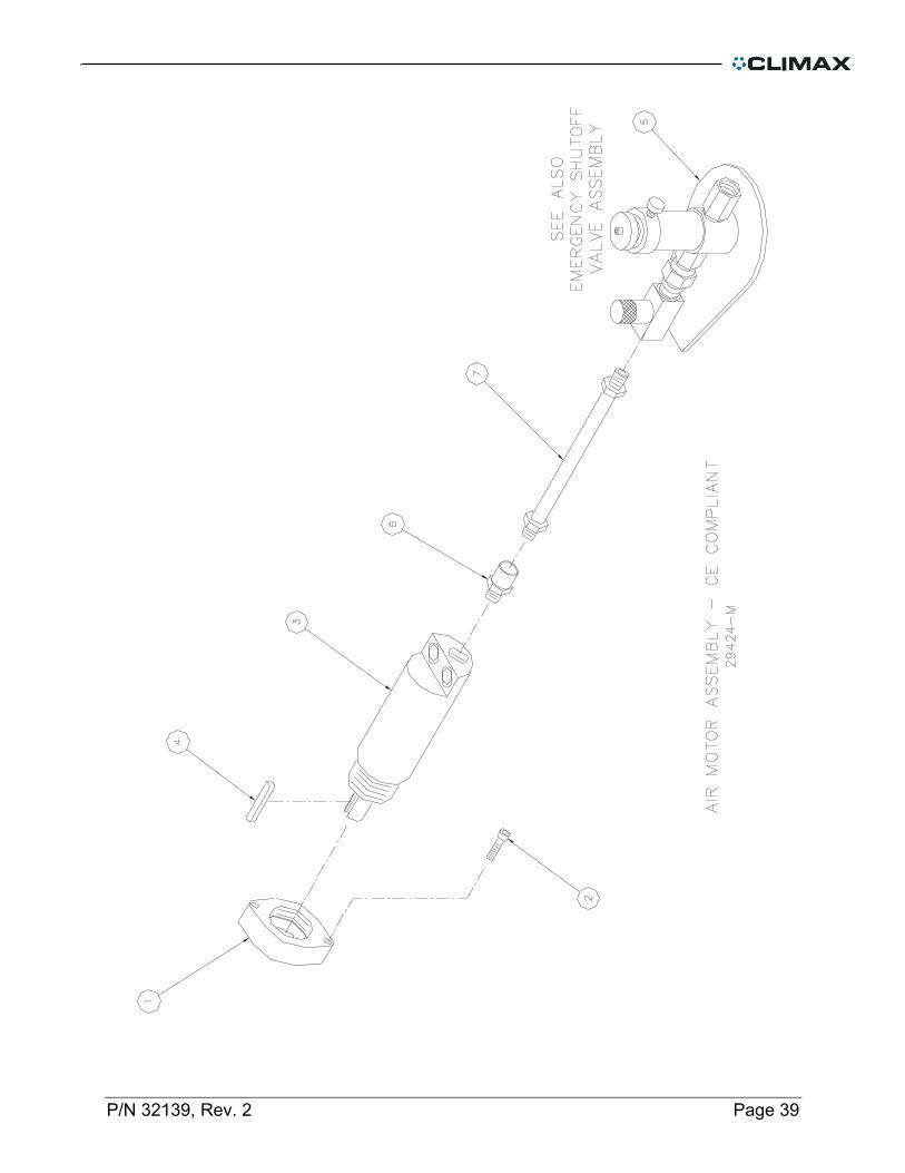
29424 MOTOR AIR ASSY STANLEY MODULATHE CE BALLOON No PART DESCRIPTION
1 10805 FLANGE MOTOR MODLTH 2 10431 SCREW 5/16-18 X 1 SHCS 3 10828 MOTOR AIR STANLEY 1600 RPM FS 820 RPM LS 4 10803 KEY 3/16 X .135 X 1.00 SQ BOTH ENDS 5 29175 VALVE ASSY EMERGENCY AIR SHUTOFF 6 29445 OBS USE 15970 7 15915 HOSE ASSY 801 1/2 X 1/2 NPTM X 1/2 NPTMS X 72
NOT SHOWN 22546 LABEL AIR MOTOR
P/N 32139, Rev. 2 Page 39
Page 40 FF1000 Operating Manual
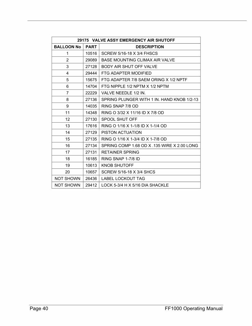
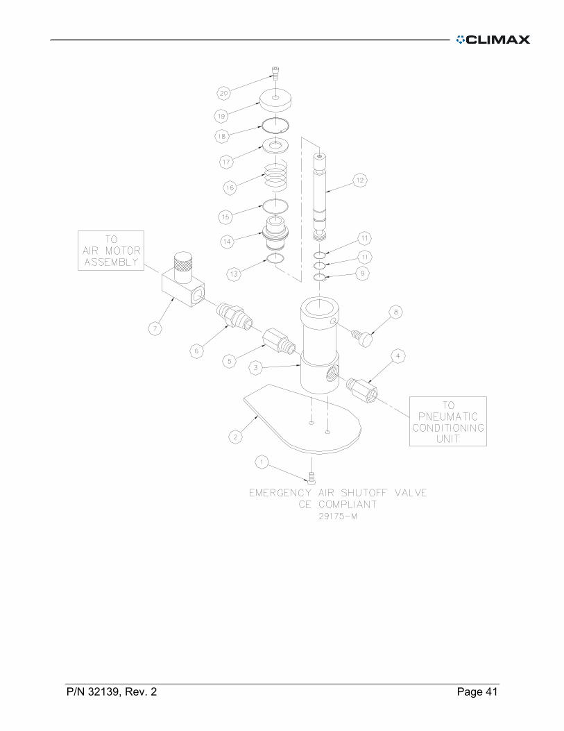
29175 VALVE ASSY EMERGENCY AIR SHUTOFF BALLOON No PART DESCRIPTION
1 10516 SCREW 5/16-18 X 3/4 FHSCS 2 29089 BASE MOUNTING CLIMAX AIR VALVE 3 27128 BODY AIR SHUT OFF VALVE 4 29444 FTG ADAPTER MODIFIED 5 15675 FTG ADAPTER 7/8 SAEM ORING X 1/2 NPTF 6 14704 FTG NIPPLE 1/2 NPTM X 1/2 NPTM 7 22229 VALVE NEEDLE 1/2 IN. 8 27136 SPRING PLUNGER WITH 1 IN. HAND KNOB 1/2-13 9 14035 RING SNAP 7/8 OD 11 14348 RING O 3/32 X 11/16 ID X 7/8 OD 12 27130 SPOOL SHUT OFF 13 17616 RING O 1/16 X 1-1/8 ID X 1-1/4 OD 14 27129 PISTON ACTUATION 15 27135 RING O 1/16 X 1-3/4 ID X 1-7/8 OD 16 27134 SPRING COMP 1.68 OD X .135 WIRE X 2.00 LONG 17 27131 RETAINER SPRING 18 16185 RING SNAP 1-7/8 ID 19 10613 KNOB SHUTOFF 20 10657 SCREW 5/16-18 X 3/4 SHCS
NOT SHOWN 26436 LABEL LOCKOUT TAG NOT SHOWN 29412 LOCK 5-3/4 H X 5/16 DIA SHACKLE
P/N 32139, Rev. 2 Page 41
Page 42 FF1000 Operating Manual
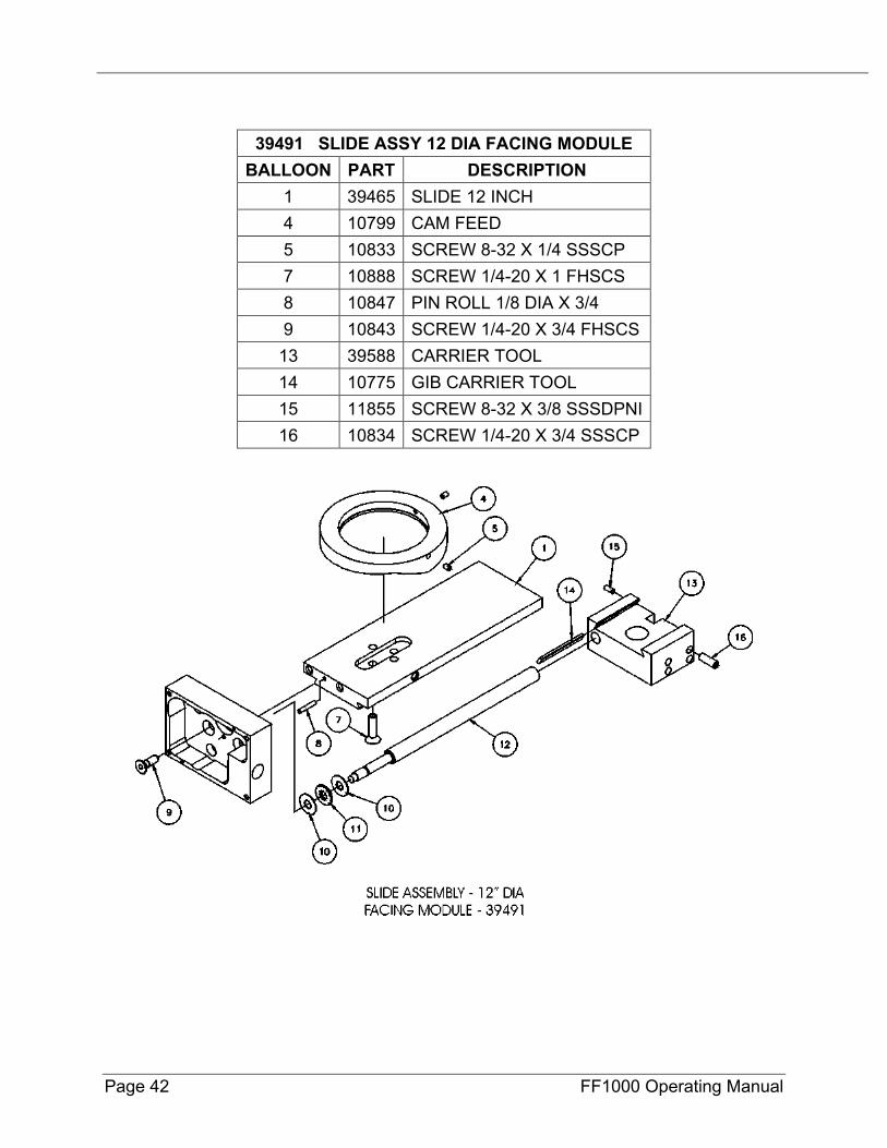
39491 SLIDE ASSY 12 DIA FACING MODULE BALLOON PART DESCRIPTION
1 39465 SLIDE 12 INCH 4 10799 CAM FEED 5 10833 SCREW 8-32 X 1/4 SSSCP 7 10888 SCREW 1/4-20 X 1 FHSCS 8 10847 PIN ROLL 1/8 DIA X 3/4 9 10843 SCREW 1/4-20 X 3/4 FHSCS
13 39588 CARRIER TOOL 14 10775 GIB CARRIER TOOL 15 11855 SCREW 8-32 X 3/8 SSSDPNI 16 10834 SCREW 1/4-20 X 3/4 SSSCP
P/N 32139, Rev. 2 Page 43
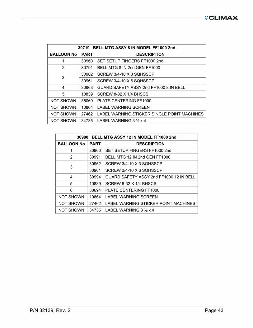
30719 BELL MTG ASSY 8 IN MODEL FF1000 2nd BALLOON No PART DESCRIPTION
1 30960 SET SETUP FINGERS FF1000 2nd 2 30791 BELL MTG 8 IN 2nd GEN FF1000
3 30962 SCREW 3/4-10 X 3 SQHSSCP 30961 SCREW 3/4-10 X 6 SQHSSCP
4 30963 GUARD SAFETY ASSY 2nd FF1000 8 IN BELL 5 10839 SCREW 8-32 X 1/4 BHSCS
NOT SHOWN 35069 PLATE CENTERING FF1000 NOT SHOWN 10864 LABEL WARNING SCREEN NOT SHOWN 27462 LABEL WARNING STICKER SINGLE POINT MACHINES NOT SHOWN 34735 LABEL WARNING 3 ½ x 4
30990 BELL MTG ASSY 12 IN MODEL FF1000 2nd BALLOON No PART DESCRIPTION
1 30960 SET SETUP FINGERS FF1000 2nd 2 30991 BELL MTG 12 IN 2nd GEN FF1000
3 30962 SCREW 3/4-10 X 3 SQHSSCP 30961 SCREW 3/4-10 X 6 SQHSSCP
4 30994 GUARD SAFETY ASSY 2nd FF1000 12 IN BELL 5 10839 SCREW 8-32 X 1/4 BHSCS 6 30694 PLATE CENTERING FF1000
NOT SHOWN 10864 LABEL WARNING SCREEN NOT SHOWN 27462 LABEL WARNING STICKER POINT MACHINES NOT SHOWN 34735 LABEL WARNING 3 ½ x 4

Page 44 FF1000 Operating Manual
P/N 32139, Rev. 2 Page 45
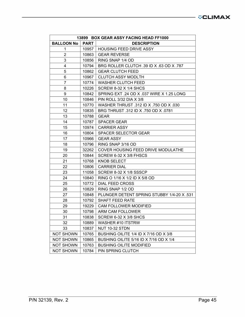
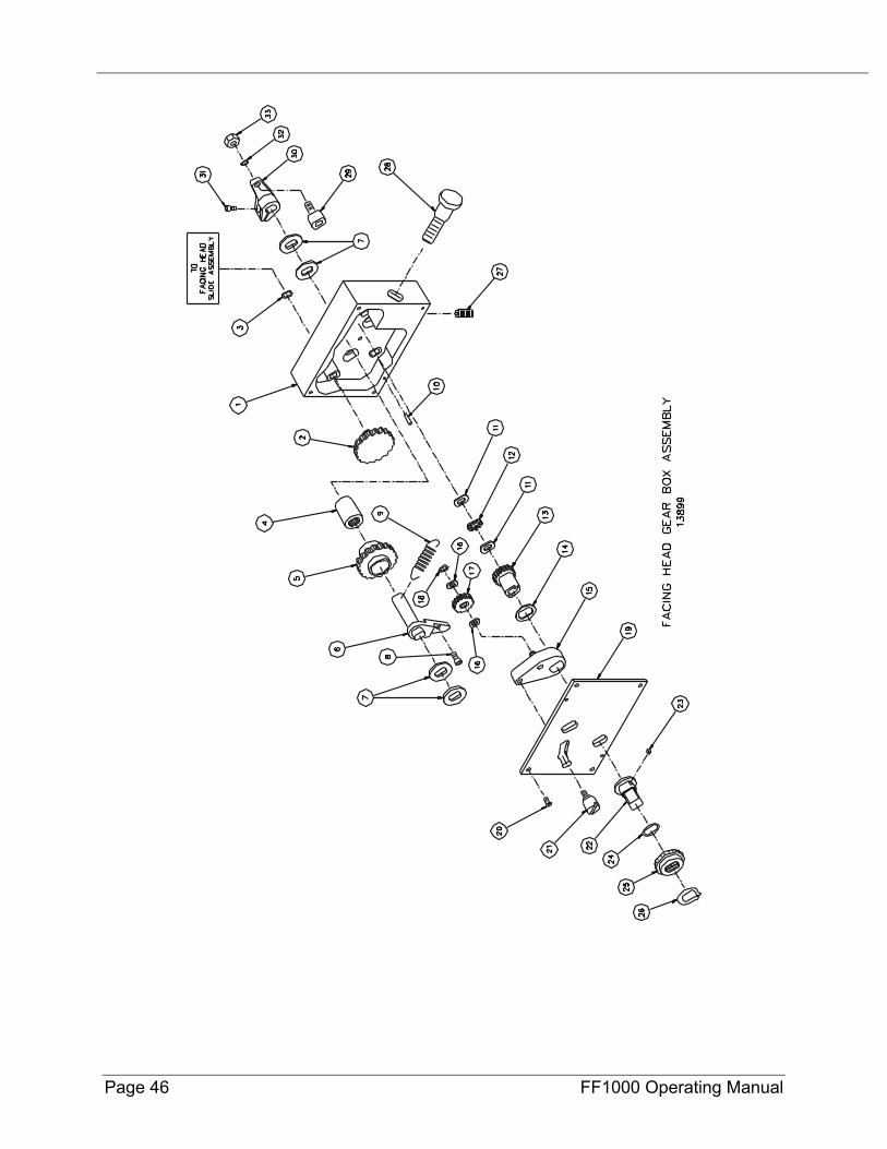
13899 BOX GEAR ASSY FACING HEAD FF1000 BALLOON No PART DESCRIPTION
1 10957 HOUSING FEED DRIVE ASSY 2 10863 GEAR REVERSE 3 10856 RING SNAP 1/4 OD 4 10794 BRG ROLLER CLUTCH .39 ID X .63 OD X .787 5 10862 GEAR CLUTCH FEED 6 10967 CLUTCH ASSY MODLTH 7 10774 WASHER CLUTCH FEED 8 10226 SCREW 8-32 X 1/4 SHCS 9 10842 SPRING EXT .24 OD X .037 WIRE X 1.25 LONG 10 10846 PIN ROLL 3/32 DIA X 3/8 11 10770 WASHER THRUST .312 ID X .750 OD X .030 12 10835 BRG THRUST .312 ID X .750 OD X .0781 13 10788 GEAR 14 10787 SPACER GEAR 15 10974 CARRIER ASSY 16 10804 SPACER SELECTOR GEAR 17 10966 GEAR ASSY 18 10796 RING SNAP 3/16 OD 19 32262 COVER HOUSING FEED DRIVE MODULATHE 20 10844 SCREW 6-32 X 3/8 FHSCS 21 10768 KNOB SELECT 22 10806 CARRIER DIAL 23 11058 SCREW 8-32 X 1/8 SSSCP 24 10840 RING O 1/16 X 1/2 ID X 5/8 OD 25 10772 DIAL FEED CROSS 26 10829 RING SNAP 1/2 OD 27 10848 PLUNGER DETENT SPRING STUBBY 1/4-20 X .531 28 10792 SHAFT FEED RATE 29 19229 CAM FOLLOWER MODIFIED 30 10798 ARM CAM FOLLOWER 31 10838 SCREW 6-32 X 3/8 SHCS 32 10889 WASHER #10 ITSTRW 33 10837 NUT 10-32 STDN
NOT SHOWN 10765 BUSHING OILITE 1/4 ID X 7/16 OD X 3/8 NOT SHOWN 10865 BUSHING OILITE 5/16 ID X 7/16 OD X 1/4 NOT SHOWN 10763 BUSHING OILITE MODIFIED NOT SHOWN 10784 PIN SPRING CLUTCH
Page 46 FF1000 Operating Manual
P/N 32139, Rev. 2 Page 47
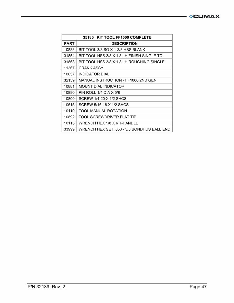
35185 KIT TOOL FF1000 COMPLETE PART DESCRIPTION 10883 BIT TOOL 3/8 SQ X 1-3/8 HSS BLANK 31854 BIT TOOL HSS 3/8 X 1.3 LH FINISH SINGLE TC 31863 BIT TOOL HSS 3/8 X 1.3 LH ROUGHING SINGLE 11367 CRANK ASSY 10857 INDICATOR DIAL 32139 MANUAL INSTRUCTION - FF1000 2ND GEN 10881 MOUNT DIAL INDICATOR 10880 PIN ROLL 1/4 DIA X 5/8 10800 SCREW 1/4-20 X 1/2 SHCS 10615 SCREW 5/16-18 X 1/2 SHCS 10110 TOOL MANUAL ROTATION 10892 TOOL SCREWDRIVER FLAT TIP 10113 WRENCH HEX 1/8 X 6 T-HANDLE 33999 WRENCH HEX SET .050 - 3/8 BONDHUS BALL END

Page 48 FF1000 Operating Manual
This page is intentionally left blank

