model cyk compound centrifugal liquid chillers … cyk compound centrifugal liquid chillers design...
TRANSCRIPT
Model CYK Compound Centrifugal Liquid ChillersDesign Level G
600 Through 2500 NOMINAL TONS(2100 Through 8800 kW)
Utilizing HFC-134a
FORM 160.82-EG1 (1110)

2 JOHNSON CONTROLS
FORM 160.82-EG1 (1110)
Table of ContentsFORM 160.82-EG1 (1110) ...................................................................................................................................................................................... 1Introduction ........................................................................................................................................................................................................... 3Mechanical Specifications ................................................................................................................................................................................... 5Accessories and Modifications ..........................................................................................................................................................................11Application Data ................................................................................................................................................................................................. 12Overall Chiller Arrangement .............................................................................................................................................................................. 19Compact Nozzle Arrangements ........................................................................................................................................................................ 20Marine Nozzle Arrangements ............................................................................................................................................................................ 26Guide Specifications .......................................................................................................................................................................................... 30SI Metric Conversion .......................................................................................................................................................................................... 36
NOMENCLATURE
�����������������������������������������������������������������������������������������������������
��� �
���� �����
��� �����
�������� ������ ������
������������������������ ������ ������
�� ������ ����
� ���� � ��������������
��������� ���������� ���
�������� ���������� ����������
��� �������������������������������������������������������������������������������
���� �����������������������������������������
FORM 160.82-EG1 (1110)
3JOHNSON CONTROLS
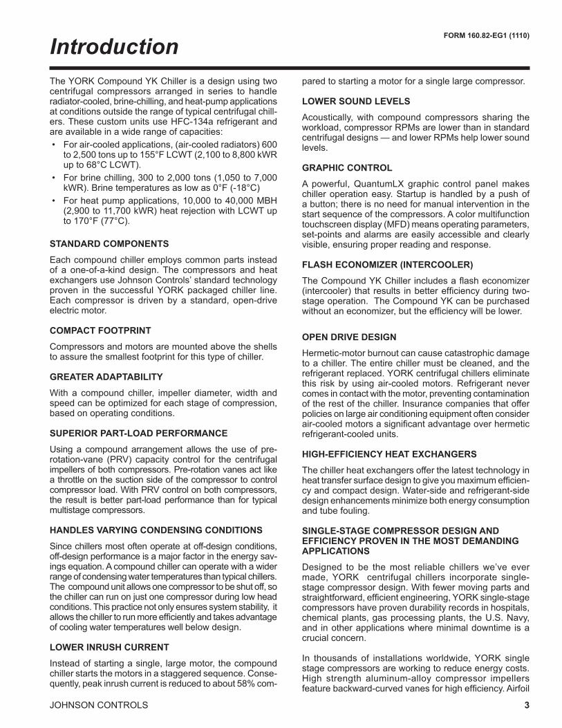
The YORK Compound YK Chiller is a design using two centrifugal compressors arranged in series to handle radiator-cooled, brine-chilling, and heat-pump applications at conditions outside the range of typical centrifugal chill-ers. These custom units use HFC-134a refrigerant and are available in a wide range of capacities: • For air-cooled applications, (air-cooled radiators) 600
to 2,500 tons up to 155°F LCWT (2,100 to 8,800 kWR up to 68°C LCWT).
• For brine chilling, 300 to 2,000 tons (1,050 to 7,000 kWR). Brine temperatures as low as 0°F (-18°C)
• For heat pump applications, 10,000 to 40,000 MBH (2,900 to 11,700 kWR) heat rejection with LCWT up to 170°F (77°C).
STANDARD COMPONENTS
Each compound chiller employs common parts instead of a one-of-a-kind design. The compressors and heat exchangers use Johnson Controls’ standard technology proven in the successful YORK packaged chiller line. Each compressor is driven by a standard, open-drive electric motor.
COMPACT FOOTPRINT
Compressors and motors are mounted above the shells to assure the smallest footprint for this type of chiller.
GREATER ADAPTABILITY
With a compound chiller, impeller diameter, width and speed can be optimized for each stage of compression, based on operating conditions.
SUPERIOR PART-LOAD PERFORMANCE
Using a compound arrangement allows the use of pre-rotation-vane (PRV) capacity control for the centrifugal impellers of both compressors. Pre-rotation vanes act like a throttle on the suction side of the compressor to control compressor load. With PRV control on both compressors, the result is better part-load performance than for typical multistage compressors.
HANDLES VARYING CONDENSING CONDITIONS
Since chillers most often operate at off-design conditions, off-design performance is a major factor in the energy sav-ings equation. A compound chiller can operate with a wider range of condensing water temperatures than typical chillers. The compound unit allows one compressor to be shut off, so the chiller can run on just one compressor during low head conditions. This practice not only ensures system stability, it allows the chiller to run more efficiently and takes advantage of cooling water temperatures well below design.
LOWER INRUSH CURRENT
Instead of starting a single, large motor, the compound chiller starts the motors in a staggered sequence. Conse-quently, peak inrush current is reduced to about 58% com-
pared to starting a motor for a single large compressor.
LOWER SOUND LEVELS
Acoustically, with compound compressors sharing the workload, compressor RPMs are lower than in standard centrifugal designs — and lower RPMs help lower sound levels.
GRAPHIC CONTROL
A powerful, QuantumLX graphic control panel makes chiller operation easy. Startup is handled by a push of a button; there is no need for manual intervention in the start sequence of the compressors. A color multifunction touchscreen display (MFD) means operating parameters, set-points and alarms are easily accessible and clearly visible, ensuring proper reading and response.
FLASH ECONOMIZER (INTERCOOLER)
The Compound YK Chiller includes a flash economizer (intercooler) that results in better efficiency during two- stage operation. The Compound YK can be purchased without an economizer, but the efficiency will be lower.
OPEN DRIVE DESIGN
Hermetic-motor burnout can cause catastrophic damage to a chiller. The entire chiller must be cleaned, and the refrigerant replaced. YORK centrifugal chillers eliminate this risk by using air-cooled motors. Refrigerant never comes in contact with the motor, preventing contamination of the rest of the chiller. Insurance companies that offer policies on large air conditioning equipment often consider air-cooled motors a significant advantage over hermetic refrigerant-cooled units.
HIGH-EFFICIENCY HEAT EXCHANGERS
The chiller heat exchangers offer the latest technology in heat transfer surface design to give you maximum efficien-cy and compact design. Water-side and refrigerant-side design enhancements minimize both energy consumption and tube fouling.
SINGLE-STAGE COMPRESSOR DESIGN AND EFFICIENCY PROVEN IN THE MOST DEMANDING APPLICATIONS
Designed to be the most reliable chillers we’ve ever made, YORK centrifugal chillers incorporate single-stage compressor design. With fewer moving parts and straightforward, efficient engineering, YORK single-stage compressors have proven durability records in hospitals, chemical plants, gas processing plants, the U.S. Navy, and in other applications where minimal downtime is a crucial concern.
In thousands of installations worldwide, YORK single stage compressors are working to reduce energy costs. High strength aluminum-alloy compressor impellers feature backward-curved vanes for high efficiency. Airfoil
Introduction

4 JOHNSON CONTROLS
FORM 160.82-EG1 (1110)
shaped pre-rotation vanes minimize flow disruption for the most efficient part load performance. Precisely positioned and tightly fitted, they allow the compressor to unload smoothly from 100% to minimum load for excellent opera-tion in all applications.
PRECISION CONTROL OF COMPRESSOR OIL PRESSURE
Using our expertise in variable speed drive technology and applications, Johnson Controls has moved beyond the fixed head and bypass approach of oil pressure control. The old approach only assures oil pressure at the outlet of the pump rather than at the compressor, and allows no adjustment during chiller operation. The CYK chillers feature two vari-able speed drive oil pumps, monitoring and providing the right amount of oil flow to each compressor on a continuous basis. This design also provides sophisticated electronic monitoring and protection of the oil pump electrical supply, ensuring long life and reliable operation of the oil pump mo-tor. Variable speed drive technology reduces oil pump power consumption, running only at the speed required, rather than at full head with a pressure regulating bypass valve.
FACTORY PACKAGING REDUCES FIELD LABOR COSTS
CYK centrifugal chillers are designed to keep installation costs low. Where installation access is not a problem, the unit can be shipped completely or partially pack-aged, requiring minimal piping and wiring to complete the installation.
The flash economizer (intercooler) ships separately for assembly to the chiller at time of installation. All piping between the economizer and the chiller is prefabricated so no welding is required for installation.
TAKE ADVANTAGE OF COLDER COOLING TOWER WATER TEMPERATURES
YORK centrifugal chillers have been designed to take full advantage of colder cooling tower water temperatures, which are naturally available during most operating hours. Considerable energy savings are available by letting tower water temperature drop, rather than artificially holding it above 75°F (23.9°C), especially at low load, as some chillers require.
HEAT PUMP
The CYK is ideal for use in heat pump applications sup-plying up to 155°F (68.3°C) leaving condenser water temperature. In this application, the CYK can provide coefficients of performance over 4 times greater than wa-ter heaters. More information on heat pump applications can be found in Johnson Controls Form 160.00-PM31.
COMPUTERIZED PERFORMANCE RATINGS
Each chiller is custom-matched to meet the individual building load and energy requirements. Standard heat exchanger tube bundle sizes and pass arrangements, are available to provide the best possible match. It is not practical to provide tabulated performance for each com-bination, as the energy requirements at both full and part load vary significantly with each heat exchanger and pass arrangement. Computerized ratings are available through each Johnson Controls sales office. These ratings can be tailored to specific job requirements.
Introduction - continued
FORM 160.82-EG1 (1110)
5JOHNSON CONTROLS
Mechanical SpecificationsGENERAL
The YORK CYK Compound Centrifugal Liquid Chillers are factory-packaged including the evaporator, condenser, compressor, motor, lubrication system, control center, and interconnecting unit piping and wiring. The flash econo-mizer (intercooler) ships loose for assembly to the chiller at time of installation. All piping between the economizer and the chillers is prefabricated in the factory so no weld-ing is required in the field.
The initial charge of refrigerant and oil is supplied for each chiller. Actual shipping procedures will depend on a number of project-specific details.
COMPRESSOR
Each compressor is a single-stage centrifugal type powered by an open-drive electric motor. The casing is fully acces-sible with vertical circular joints and fabricated of close-grain cast iron. The complete operating assembly is removable from the compressor and scroll housing.
The rotor assembly consists of a heat-treated alloy steel drive shaft and impeller shaft with a high strength, cast aluminum alloy, fully shrouded impeller. The impeller is designed for balanced thrust and is dynamically balanced and overspeed tested for smooth, vibration free operation.
The insert-type journal and thrust bearings are fabricated of aluminum alloy and are precision bored and axially grooved. The specially engineered, single helical gears with crowned teeth are designed so that more than one tooth is in contact at all times to provide even distribu-tion of compressor loads and quiet operation. Gears are integrally assembled in the compressor rotor support and are film lubricated. Each gear is individually mounted in its own journal and thrust bearings to isolate it from impeller and motor forces.
FLASH ECONOMIZER (INTERCOOLER)
The flash economizer (intercooler) is a single stage de-sign. It consists of a vertical pressure vessel with internally mounted mesh eliminators and liquid spray pipe, an ex-ternally mounted (field installed) level transmitter located with a liquid level pipe assembly, and an external control valve mounted in the liquid outlet to the evaporator. Re-frigerant from the condenser, after expanding through the condenser subcooler level control valve, enters through the internal spray pipe, where flash gas is removed and channeled through the mesh eliminator, out the top and onto the high stage compressor section. The remaining liquid feeds out of the economizer through a liquid level control valve into the evaporator. Eight sight glasses are provided: two above and two below the mesh eliminators;
two at the liquid spray pipe; and two in the liquid line leav-ing the economizer. A thermometer well is furnished for checking the liquid temperature. Connections are provided for the Johnson Controls furnished, field installed pressure transmitter and relief valve assemblies. Three support legs of structural steel are provided with mounting brackets for spring type isolators. Refrigerant connections are as follows: high pressure liquid inlet, interstage flash gas top outlet, and low pressure liquid bottom outlet.
CAPACITY CONTROL
Pre-rotation vanes (PRV) in each compressor modulate chiller capacity from 100% to 15% of design for normal air conditioning applications. Operation is by an external, electric PRV actuator which automatically controls the vane position to maintain a constant leaving chilled liquid temperature (or leaving condenser temperature for a heat pump application). Rugged airfoil shaped cast manganese bronze vanes are precisely positioned by solid vane link-ages connected to the electric actuator.
Both compressors are normally operated to satisfy the evaporator load (or the condenser load in the case of a heat pump). Should the entering condensing water tem-perature drop below a preset temperature, a compressor will be taken off line. This allows the remaining compres-sor to continue operating more efficiently at low entering condensing water temperatures.
OPTISOUND™ CONTROL
The YORK® OptiSound™ Control is a patented combi-nation of centrifugal-chiller hardware and software that reduces operational sound levels, expands the chiller operating range, and improves chiller performance. The OptiSound Control feature continuously monitors the char-acteristics of the compressor-discharge gas and optimizes the diffuser spacing to minimize gas-flow disruptions from the impeller. This innovative technology improves operat-ing sound levels of the chiller an average of 7 dBA, and up to 13 dBA on the largest models. It can also reduce part-load sound levels below the full-load level.
In addition, the OptiSound Control provides the benefit of an expanded operating range. It improves performance and reliability by minimizing diffuser gas stall at off-design operation, particularly conditions of very low load com-bined with little or no condenser-water relief. The elimina-tion of the gas-stall condition can also result in improved chiller efficiency at off design conditions.
Johnson Controls includes the OptiSound Control for all CYK chillers when it is available on the compressors used. It is not available on all compressors.

6 JOHNSON CONTROLS
FORM 160.82-EG1 (1110)
Mechanical Specifications - continued
LUBRICATION SYSTEM
Lubrication oil is force-fed to all bearings, gears and rotating surfaces by a variable speed drive pump; which operates prior to startup, and continuously during opera-tion and during coast-down. A gravity-fed oil reservoir is built into the top of each compressor to provide lubrica-tion during coast-down in the event of a power failure.
Dual oil reservoirs, separate from the compressors, contain the 2 HP submersible oil pumps and 1500 watt immersion-type oil heaters for each compressor. The oil heaters are thermostatically controlled to remove refrigerant from the oil.
A water-cooled oil cooler is provided after each oil pump, with factory installed water piping terminat-ing at the center on the condenser side of the unit. A thermostatically controlled bypass valve maintains the required oil temperature supply from each oil cooler to its compressor. Oil is filtered by externally mounted, 1/2 micron, replaceable cartridge oil filters, equipped with service valves. An automatic oil return system recovers any oil that may have migrated to the evaporator. Oil piping is completely factory installed.
MOTOR DRIVELINE
The compressor motors are open drip-proof, squir-rel cage, induction type constructed to YORK design specifications. 60 hertz motors operate at 3570 rpm. 50 hertz motors operate at 2975 rpm.
The open motor is provided with a D-flange, and is factory-mounted to a cast iron adapter mounted on the compressor. This unique design allows the motor to be rigidly coupled to the compressor to provide factory alignment of motor and compressor shafts.
Motor drive shaft is directly connected to the compres-sor shaft with a flexible disc coupling. Coupling has all metal construction with no wearing parts to assure long life, and no lubrication requirements to provide low maintenance.
A large, steel terminal box with gasketed front access cover is provided on each motor for field-connected con-duit. There are six terminals (three for medium voltage) brought through the motor casing into the terminal box. Jumpers are furnished for three-lead types of starting. Motor terminal lugs are not furnished.
HEAT EXCHANGERS
Shells
Evaporator and condenser shells are fabricated from rolled carbon steel plates with fusion welded seams.
Carbon steel tube sheets, drilled and reamed to accom-modate the tubes, are welded to the end of each shell. Intermediate tube supports are fabricated from carbon steel plates, drilled and reamed to eliminate sharp edges, and spaced no more than four feet apart. The refrigerant side of each shell is designed, tested, and stamped in accordance with ASME Boiler and Pressure Vessel Code, Section VIII – Division I.
Tubes
Heat exchanger tubes are state-of-the-art, high-efficien-cy, externally and internally enhanced type to provide optimum performance. Tubes in both the evaporator and condenser are 3/4” or 1” O.D. copper alloy and utilize the “skip-fin” design, providing a smooth internal and external surface at each intermediate tube support. This provides extra wall thickness (up to twice as thick) and non-work hardened copper at the support location, extending the life of the heat exchangers. Each tube is roller expanded into the tube sheets providing a leak-proof seal, and is individually replaceable.
Evaporator
The evaporator is a shell and tube, flooded type heat exchanger. A distributor trough provides uniform distri-bution of refrigerant over the entire shell length to yield optimum heat transfer. Mesh eliminators or baffles are located above the tube bundle to prevent liquid refriger-ant carryover into the compressor. A 1.5” (38mm) liquid level sight glass is conveniently located on the side of the shell to aid in determining proper refrigerant charge. The evaporator shell contains a dual refrigerant relief valve arrangement set to pressures up to 235 psig (16.2 barg). A 1” refrigerant charging valve is provided.
Condenser
The condenser is a shell and tube type, with discharge gas baffles to prevent direct high velocity impingement on the tubes. The baffles are also used to distribute the refrigerant gas flow properly for most efficient heat transfer. An integral sub-cooler is located at the bot-tom of the condenser shell providing highly effective liquid refrigerant sub-cooling to provide the highest cycle efficiency. The condenser contains dual refriger-ant relief valves that can be set to pressures up to 350 psig (24.1 barg).
WATER BOXES
The removable water boxes are fabricated of steel. The design working pressure is 150 psig (10.3 barg) and the boxes are tested at 225 psig (15.5 barg). Integral steel water baffles are located and welded within the water box to provide the required pass arrangements. Stub-out water nozzle connections with ANSI/AWWA
FORM 160.82-EG1 (1110)
7JOHNSON CONTROLS
C-606 grooves are welded to the water boxes. These nozzle connections are suitable for ANSI/AWWA C-606 couplings, welding or flanges, and are capped for ship-ment. Plugged 3/4” drain and vent connections are provided in each water box.
WATER FLOW SWITCHES
Thermal type water flow switches are factory mounted in the chilled and condenser water nozzles, and are factory wired to the control panel. These solid state flow sensors have a small internal heating element. They use the cooling effect of the flowing fluid to sense when an adequate flow rate has been established. The sealed sensor probe is 316 stainless steel, which is suited to very high working pressures.
ZERO LOAD HOT GAS BYPASS
Sized for operation to 0% evaporator load to prevent nuisance shutdowns due to low load conditions, and critical industrial and process applications.
LOW INLET CONDENSER WATER CAPABILITY
The CYK Compound chiller incorporates a control strategy that allows a compressor to shut down auto-matically when two-compressor operation is no longer required. This allows the chiller to take advantage of low-inlet condenser water temperatures to reduce en-ergy consumption.
CONTROL CENTER
The chiller is controlled by a stand-alone QuantumLX microprocessor-based control center with a Linux oper-ating system. The chiller control center provides all the necessary controls and control logic to provide automatic start-up, automatic operation, capacity control and safety protection of the chiller.
Control Panel
The control panel includes a 10.4” color active matrix MFD with integral keypad for operator interface. The control panel is a factory wired, unit mounted, NEMA 12, gasketed enclosure. The panel is fabricated of 10 gauge steel and includes a full-height front access door. The panel enclo-sure is painted to match the chiller color. All controls are arranged for easy access and internally wired to clearly marked terminal strips or pre-wired I/O Board pluggable terminations for wiring connections. Wiring is color-coded black for power, red control, light-blue (neutral), and green (ground), with each wire numerically identified at both ends with wire markers. Wiring enclosed in shielded cables and pre-wired cables are color coded per the wiring diagram.
The screen details all operations and parameters, using a graphical representation of the chiller and its compo-nents. Graphic screens are provided for: a. Chiller Overview b. Evaporator c. Condenser d. Low stage compressor e. High stage compressor f. Motors g. Capacity control diagram h. Manual/Auto stations for all control outputs
The MFD is programmed to provide display of all major operating parameters in both graphical and list type screen displays. PID control loop set points, and Manual/Auto functions are also accessed by the MFD. Operator interaction is provided by a touchscreen interface. Alarm indicators on the MFD provide annunciation, and an alarm history screen is provided which shows the most recent alarms, with the time and date of occurrence. Trip status screens are provided which show the values of all analog inputs at the time of the last 128 chiller safety shutdowns. The time and date of the shutdown are also shown. Func-tion keys are provided on the keypad for Chiller Start, Stop, Reset and Emergency Stop.
Capacity Controls System
The Capacity Control philosophy of the York CYK chiller control system allows efficient, fully automated control, without need for operator intervention. This control system also monitors and displays all safety aspects of the chiller and provides alarms and a shutdown if safety limits are exceeded. If operator intervention is required, manual controls are provided on the MFD for all electric actuators.
The capacity controls algorithm automatically seeks out the most efficient operation of the CYK chiller. The pre-rotation vanes are adjusted to maintain chilled water production. In cases of low load, the pre-rotation vanes automatically throttle and are limited to a minimum anti-surge position. To provide light duty operation, the hot gas recycle valve is seamlessly throttled open according to temperature demands. This keeps the centrifugal compressor out of surge and maintains chilled water production.
In cases of high load, which exceeds the motor kilowatt (or current) usage, the capacity controls algorithm auto-matically unloads the system to maintain a restriction on power consumption. In the same way, conditions of high discharge pressure or low suction pressure override the production of chilled water in the interests of keeping the chiller system online.

8 JOHNSON CONTROLS
FORM 160.82-EG1 (1110)
Mechanical Specifications - continued
In cases of light load and low head, the high compressor is dropped offline, the intercooler (if provided) bypassed, and the unit will be run with the low stage compressor like a normal single compressor chiller.
The Heat Pump is limited to produce heat on the avail-able heat extracted from the chilled water loop. If there is insufficient load on the chilled water loop, then hot gas will generate as much heat as it can to make up the lack of source heat from the chilled loop. More importantly the Heat Pump must have sufficient load on the condenser (heating) side to carry away the heat of compression of the system. The Design working pressure of the condenser vessel is the limiting factor of the hot water production. On the condenser side of the heat pump, if the load is less than the heat of compression load plus the refrigeration effect, the system will not be able to stay online as the total heat generated in the heat pump is not removed from the heating water loop and will accumulate causing a high pressure shutdown.
Heat Pump mode and Chiller/Heat Recovery capacity con-trols operation are mutually exclusive operational modes. The Chiller mode produces cold water at setpoint, and any hot water recovered simply a benefit. The inverse is also true. Whichever limitation is reached first becomes the limiting factor and the Heat Pump will unload based on low water temperature or high discharge pressure. There are also limitations on the lift of the single stage centrifugal compressor if the chilled water loop gets too low, which will result in wide-open vane surge if exceeded.
Analog Input List:
1. Low Stage Motor Current (% FLA) 2. High Stage Motor Current (% FLA) 3. Subcooler Refrigerant Liquid Level 4. Low Stage Oil Reservoir Oil Level (Brine Units) 5. High Stage Oil Reservoir Oil Level (Brine Units) 6. Evaporator Refrigerant Pressure 7. Condenser Refrigerant Pressure 8. Low Stage Compressor Low Oil Pressure 9. Low Stage Compressor High Oil Pressure 10. High Stage Compressor Low Oil Pressure 11. High Stage Compressor High Oil Pressure 12. Chilled Water-Out Temperature. 13. Chilled Water-In Temperature. 14. Condenser Water In Temperature 15. Condenser Water Out Temperature 16. Evaporator Refrigerant Liquid Temp. 17. Low Stage Compressor Refrigerant Discharge Tem-
perature
18. High Stage Compressor Refrigerant Discharge Tem-perature
19. Subcooled Refrigerant Liquid Temperature 20. Low Stage Compressor Oil Temperature 21. High Stage Compressor Oil Temperature 22. Low Stage PRV Position 23. High Stage PRV Position 24. Low Stage Compressor high stage thrust Bearing
Probe Gap 25. High Stage Compressor thrust bearing Probe gap 26. Flash Economizer Pressure 27. Flash Economizer Refrigerant Liquid Level
Digital Inputs:
1 . Chilled Water Low Flow Switch 2. Condenser Water Low Flow Switch 3. Low Stage Motor Starter Full Voltage (Run) Auxiliary
Contact 4. High Stage Motor Starter Full Voltage (Run) Auxiliary
Contact5. Low Stage Motor Starter Safety Fault Lockout Relay6. High Stage Motor Starter Safety Fault Lockout Relay7. Condenser Refrigerant High Pressure Cutout8. Low Stage Compressor Oil Heater Thermostat9. High Stage Compressor Oil Heater Thermostat 10. Low Stage PRV Closed Limit Switch 11. High Stage PRV Closed Limit Switch 12. Low Stage Compressor V.S. Oil Pump Drive Faulted
Contact 13. High Stage Compressor V.S. Oil Pump Drive Faulted
Contact 14. Optional Remote Chiller Start Input 15. Emergency Stop
OptiSound inputs (when available)
1. LS VGD Position2. LS VGD Stall Sensor3. HS VGD Position4. HS VGD Stall Sensor
Analog Output List
1. Hot Gas Bypass Valve 2. Low Stage Compressor, V.S. Oil Pump Drive Control 3. High Stage Compressor, V.S. Oil Pump Drive Control 4. High Pressure Variable Orifice Valve LCV-114 5. Low Pressure Variable Orifice Valve LCV-116
FORM 160.82-EG1 (1110)
9JOHNSON CONTROLS
6. Bypass Level Control valve output LCV-117
Digital Output List 1. Low Stage Liquid Line Solenoid Valve 2. High Stage Liquid Line Solenoid Valve 3. High Stage Oil Return Solenoid (brine units only)4. Low Stage Oil Return Solenoid Valve 5. Low Stage Compressor Oil Heater Contactor 6. High Stage Compressor Oil Heater Contactor 7. Low Stage Compressor Motor Start/Stop Control Relay 8. High Stage Compressor Motor Start/Stop Control
Relay 9. Low Stage Compressor Oil Pump Start/Stop Relay 10. High Stage Compressor Oil Pump Start/Stop Relay 11. Oil Level Control Pump Start/Stop Relay (brine units
only) 12. Open Low Stage PRV 13. Open High Stage PRV 14. Close Low Stage PRV 15. Close High Stage PRV16. Interstage Sideload Valve
Optisound Control Outputs (when available)
1. Open Low Stage VGD2. Close Low Stage VGD3. Open High Stage VGD4. Close Hgh Stage VGD
Security
Security access to prevent unauthorized change of set-points, to allow local or remote control of the chiller, and to allow manual operation of the pre-rotation vanes and oil pump. Access is through ID and password recognition, which is defined by three different levels of user compe-tence: operator, service and factory.
Over-Current Protection
A fused connection through a transformer on the Vari-able Speed Oil Pump Panel to provide individual over-current protected power for all controls.
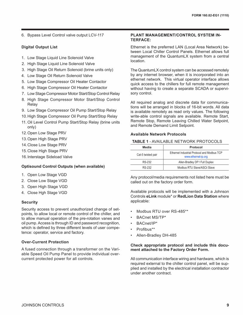
PLANT MANAGEMENT/CONTROL SYSTEM IN-TERFACE:
Ethernet is the preferred LAN (Local Area Network) be-tween Local Chiller Control Panels. Ethernet allows full management of the QuantumLX system from a central location.
The QuantumLX control system can be accessed remotely by any internet browser, when it is incorporated into an ethernet network. This virtual operator interface allows quick access to the chillers for full remote management without having to create a separate SCADA or supervi-sory control.
All required analog and discrete data for communica-tions will be arranged in blocks of 16-bit words. All data is available remotely as read only values. The following write-able control signals are available. Remote Start, Remote Stop, Remote Leaving Chilled Water Setpoint, and Remote Demand Limit Setpoint.
Available Network Protocols
Any protocol/media requirements not listed here must be called out on the factory order form.
Available protocols will be implemented with a Johnson Controls eLink module* or RedLion Data Station where applicable:
• Modbus RTU over RS-485**• BACnet MS/TP*• BACnet/IP*• Profibus**• Allen-Bradley DH-485
Check appropriate protocol and include this docu-ment attached to the Factory Order Form.
All communication interface wiring and hardware, which is required external to the chiller control panel, will be sup-plied and installed by the electrical installation contractor under another contract.
TABLE 1 - AVAILABLE NETWORK PROTOCOLSMedia Protocol
Cat-5 twisted pair Ethernet Industrial Protocol and Modbus TCPwww.ethernet-ip.org
RS-232 Allen-Bradley DF1 Full DuplexRS-232 Modbus RTU Slave/ASCii Slave

10 JOHNSON CONTROLS
FORM 160.82-EG1 (1110)
CODES AND STANDARDS • ASME Boiler and Pressure Vessel Code – Section
Vlll Division 1. • ARI Standard 550/590 (When applicable) • ASHRAE 15 – Safety Code for Mechanical Refrig-
eration • ASHRAE Guideline 3 – Reducing Emission of
Halogenated Refrigerants in Refrigeration and Air-Conditioning Equipment and Systems
• N.E.C. – National Electrical Code • OSHA – Occupational Safety and Health Act
ISOLATION MOUNTING
The unit is provided with four vibration isolation mounts consisting of 1” (25.4 mm) thick neoprene isolation pads for field mounting under the steel mounting pads located on the tube sheets and three pads for the flash economizer (intercooler).
REFRIGERANT CONTAINMENT
The standard unit has been designed as a complete and compact factory-packaged chiller except for the flash economizer. The piping between the economizer and the main chiller is all prefabricated in the factory with
strategically placed flanges. No field welding is neces-sary to attach the economizer. As such, it has minimum joints from which refrigerant can leak. The entire assem-bly has been thoroughly leak tested at the factory prior to shipment. The YORK chiller includes service valves, conveniently located to facilitate transfer of refrigerant to a remote refrigerant storage/recycling system.
PAINT
Exterior surfaces are protected with one coat of Ca-ribbean blue, durable alkyd-modified, vinyl enamel, machinery paint.
SHIPMENTProtective covering is furnished on the motor, Control Center and unit-mounted controls. Water nozzles are capped with fitted plastic enclosures. Entire unit is pro-tected with industrial-grade, reinforced shrink-wrapped covering. The flash economizer (intercooler) is removed for shipment. Flanged joints are provided and all piping is prefabricated.
Mechanical Specifications - continued
�����
������������������������������
�����
��� ������
������������������������
�������� ����
���� �� ����������� ����� �
�����

FORM 160.82-EG1 (1110)
11JOHNSON CONTROLS
BAS REMOTE CONTROL
Alternate network mediums and protocols may be accom-plished with the addition of a protocol translator gateway. See Available Protocals List on pg. 9.
FACTORY INSULATION
Factory-applied thermal insulation of the flexible, closed-cell plastic type, 3/4” (19 mm) thick is attached with vapor-proof cement to the evaporator shell, tube sheets, suction connection, and (as necessary) to the auxiliary tubing. The flash economizer (intercooler) operates near room temperature and is not insulated. For all other projects, optional factory insulation on the economizer is available upon request. Not included is the insulation of compact water boxes and nozzles. This insulation will normally pre-vent condensation in environments with relative humidities up to 75% and dry bulb temperatures ranging from 50° to 90°F (10° to 32.2°C). 1-1/2” (38 mm) thick insulation is also available for relative humidities up to 90% and dry bulb temperatures ranging from 50° to 90°F (10° to 32.2°C). For heat pump applications the condenser can be ordered with optional factory insulation to minimize heat loss to the atmosphere.
WATER FLANGES
Four 150 lb. ANSI raised-face flanges for condenser and evaporator water connections, are factory-welded to water nozzles. Companion flanges, bolts, nuts and gaskets are not included.
SPRING ISOLATION MOUNTING
Spring isolation mounting is available instead of standard isolation mounting pads when desired. Seven vertically restrained level-adjusting, spring-type vibration isolator assemblies with non-skid pads are provided for field-installation. Isolators are designed for one-inch (25 mm) deflection.
STARTER – FIELD-INSTALLED
Field installed, compressor motor starter assemblies are available, selected for proper size and type for job requirements and in accordance with Johnson Controls Engineering Standard (R-1177) for Starters. The starter assemblies have contactors and accessories for control-ling the two compressor motors per chiller. For low voltage applications up to 1050 amps, unit-mounted solid state starters are also available.
MARINE WATER BOXES
Marine water boxes allow service access for cleaning of the heat exchanger tubes without the need to break the water piping. Bolted-on covers are arranged for conve-nient access. ANSI/AWWA C-606 nozzle connections are standard; flanges are optional. Marine water boxes are
available for condenser and/or evaporator.
Hinged water boxes are available upon request.
KNOCK-DOWN SHIPMENT
The chiller can be shipped knocked down into major subassemblies (evaporator, condenser, driveline, etc.) as required to rig into tight spaces. This is particularly convenient for existing buildings where equipment room access does not allow rigging a factory-packaged chiller.
REFRIGERANT STORAGE/RECYCLING SYSTEM
A refrigerant storage/recycling system is a self-contained package consisting of a refrigerant compressor with oil separator, storage receiver, water-cooled condenser, filter drier and necessary valves and hoses to remove, replace and distill refrigerant. All necessary controls and safety devices are a permanent part of the system.
HIGH VOLTAGE MOTORS
High voltage induction motors (11 kV to 13.8 kV), spe-cial motor enclosures such as TEWAC or WPII, may be substituted.
TUBE AND/OR TUBE SHEET MATERIALS AND/OR WATER BOX COATING
For condenser and/or evaporator for protection against aggressive water conditions. Alternate cupro-nickel or titanium tubes can be provided in lieu of standard cop-per. Tube sheets may be of the clad type. Epoxy coating may be applied to water boxes or to tubesheet and water boxes.
SACRIFICIAL ZINC ANODES
With mounting hardware for condenser and/or evaporator corrosion protection.
HIGHER WATER CIRCUIT DWP
Condenser and/or evaporator water circuit(s) DWP higher than the standard 150 psig (1034 barg) DWP.
OUTDOOR AND/OR HAZARDOUS DUTY APPLICA-TIONS
Necessary unit, control and control center modifications for Outdoor (NEMA-3 & 4) application in lieu of standard NEMA-1 construction. Suitable alternate surface prepara-tion and protective coating systems also available.
FIELD PERFORMANCE TEST
Services of a factory engineer or independent consultant to supervise a field performance test. Various levels of instrumentation can be offered by Johnson Controls.
Accessories and Modifications

12 JOHNSON CONTROLS
FORM 160.82-EG1 (1110)
Application DataThe following discussion is a user’s guide in the applica-tion and installation of CYK chillers to ensure the reliable, trouble-free life for which this equipment was designed. While this guide is directed towards normal, water-chilling applications, the Johnson Controls sales repre sentative can provide complete recommendations on other types of applications.
LOCATION
CYK chillers are virtually vibration free and may generally be located at any level in a building where the construction will support the total system operating weight.
The unit site must be a floor, mounting pad or foundation which is level within 1/4” (6.4 mm) and capable of sup-porting the operating weight of the unit.
Sufficient clearance to permit normal service and main-tenance work should be provided all around and above the unit. Additional space should be provided at one end of the unit to permit cleaning of evaporator and condenser tubes as required. A doorway or other properly located opening may be used.
The chiller should be installed in an indoor location where temperatures range from 40°F to 104°F (4.4°C to 40°C).
WATER CIRCUITS
Flow Rate – For normal water chilling duty, evaporator and condenser flow rates are permitted at water velocity levels in the heat exchangers tubes of between 3.0 ft/sec and 12 ft/sec (0.91 m/s and 3.66 m/s). Variable flow ap-plications are possible, and initial chiller selections should be made accordingly to allow proper range of flow while maintaining the minimum velocity noted above. Variable flow in the condenser is not recommended, as it generally raises the energy consumption of the system by keeping the condenser pressure high in the chiller. Additionally, the rate of fouling in the condenser will increase at lower water velocities associated with variable flow, raising system maintenance costs. Cooling towers typically have narrow ranges of operation with respect to flow rates, and will be more effective with full design flow. Contact Johnson Controls Sales for specific flow limits.
Water Quality – The practical and economical applica-tion of liquid chillers requires that the quality of the water supply for the condenser and evaporator be analyzed by a water treatment specialist. Water quality may affect the performance of any chiller through corrosion, deposition of heat-resistant scale, sedimentation or organic growth. These will degrade chiller performance and increase operat ing and maintenance costs. Normally, performance may be maintained by corrective water treatment and periodic cleaning of tubes. If water conditions exist which
cannot be corrected by proper water treatment, it may be nec essary to provide a larger allowance for fouling, and/or to specify special materials of construction.
General Piping – All chilled water and condenser water piping should be designed and installed in accordance with accepted piping practice. Chilled water and con-denser water pumps should be located to discharge through the chiller to assure positive pressure and flow through the unit. Piping should include offsets to provide flexibility and should be arranged to prevent drainage of water from the evaporator and condenser when the pumps are shut off. Piping should be adequately supported and braced independently of the chiller to avoid the imposi-tion of strain on chiller components. Hangers must allow for alignment of the pipe. Isolators in the piping and in the hangers are highly desirable in achiev ing sound and vibration control.
Convenience Considerations – To facilitate the perfor-mance of routine maintenance work, some or all of the following steps may be taken by the pur chaser. Evaporator and condenser water boxes are equipped with plugged vent and drain connections. If desired, vent and drain valves may be installed with or without piping to an open drain. Pressure gauges with stop cocks and stop valves may be installed in the inlets and outlets of the condenser and chilled water line as close as possible to the chiller. An overhead monorail or beam may be used to facilitate servicing.
Connections – The standard chiller is designed for 150 psig (1034 kPA) design working pressure in both the chilled water and condenser water circuits. The connec-tions (water nozzles) to these circuits are furnished with grooves for ANSI/AWWA C-606 couplings. Piping should be arranged for ease of disassembly at the unit for tube cleaning. All water piping should be thoroughly cleaned of all dirt and debris before final connections are made to the chiller.
Condenser Water Strainer – A water strainer of maxi-mum 1/8” (3mm) perforated holes is recommended to be field installed in the refrigerant condenser water inlet line as close as possible to the chiller. If located close enough to the chiller, the condenser water pump may be protected by the same strainer. The loss or severe reduc-tion of water flow due to blockage could seriously impair the chiller’s performance.
MULTIPLE UNITS
Selection – Many applications require multiple units to meet the total capacity requirements as well as to provide flexibility and some degree of protection against equip-ment shutdown. There are several common unit arrange-

FORM 160.82-EG1 (1110)
13JOHNSON CONTROLS
ments for this type of application. The CYK chiller has been designed to be readily adapted to the requirements of these various arrangements.
Parallel Arrangement (Refer to Fig. 1) – Chillers may be applied in multiples with chilled and condenser water circuits connected in parallel between the units. Fig. 1 rep-resents a parallel arrangement with two chillers. Parallel chiller arrangements may consist of equally or unequally sized units. When multiple units are in operation, they will load and unload at equal percentages of design full load for the chiller.
Depending on the number of units and operating char-acteristics of the units, loading and unloading schemes should be designed to optimize the overall efficiency of the chiller plant. It is recommended to use an evapora-tor by-pass piping arrangement to bypass fluid around evaporator of any unit which has cycled off at reduced load conditions. It is also recommended to alternate the chiller cycling order to equalize chiller starts and run hours.
REFRIGERANT RELIEF PIPING
Each chiller is equipped with dual pressure relief valves on the condenser, dual relief valves on the evaporator and dual relief valves on the flash economizer (intercooler). The dual relief valves are redundant and allow changing of either valve while the unit is fully charged. The purpose of the relief valves is to quickly relieve excess pressure of the refrigerant charge to the atmosphere, as a safety precaution in the event of an emergency such as fire. They are set to relieve at an internal pressure as noted on the pressure vessel data plate, and are provided in
accordance with ASHRAE 15 safety code and ASME or applicable pressure vessel code.Sized to the requirements of applicable codes, a vent line must run from the relief device to the outside of the build-ing. This refrigerant relief piping must include a cleanable, vertical-leg dirt trap to catch vent-stack con densation. Vent piping must be arranged to avoid im posing a strain on the relief connection and should include one flexible connection.
SOUND AND VIBRATION CONSIDERATIONS
A YORK CYK chiller is not a source of objectionable sound and vibration in normal air conditioning applica tions. Neoprene isolation mounts are furnished as standard with each unit. Optional level-adjusting spring isolator assemblies designed for 1” (25 mm) static deflection are available from Johnson Controls. YORK CYK chiller sound pressure level ratings will be furnished on request.
Control of sound and vibration transmission must be taken into account in the equipment room construction as well as in the selection and installation of the equip ment.
THERMAL INSULATION
No appreciable operating economy can be achieved by thermally insulating the chiller. However, the chiller’s cold surfaces should be insulated with a vapor barrier insulation sufficient to prevent condensation. A chiller can be factory insulated with 3/4” (19 mm) or 1-1/2” (38 mm) thick insu-lation, as an option. This insulation will normally pre vent condensation in environments with dry bulb temperatures of 50°F to 90°F (10°C to 32°C) and relative humidities up to 75% [3/4” (19 mm) thickness] or 90% [1-1/2” (38 mm) thickness]. For heat pump applications where the condenser operating temperature is above 140°F (60°C), thermal insulation is also recommended. The insulation surface is flexible and reasonably resistant to wear. It is intended for a chiller installed indoors and, therefore, no protective covering of the insulation is usually required. If insulation is applied to the water boxes at the jobsite, it must be removable to permit access to the tubes for routine maintenance. For heat pump applications the condenser can be ordered with optional factory insulation to minimize heat loss to the atmosphere.
VENTILATION
The ASHRAE Standard 15 Safety Code for Mechanical Refrigeration requires that all machinery rooms be vented to the outdoors using mechanical ventilation by one or more power-driven fans. This standard, plus National Fire Protection Association Standard 90A, state, local and any other related codes should be reviewed for specific requirements. Since the CYK chiller mo tor is air-cooled,
FIG. 1 – PARALLEL EVAPORATORS PARALLEL CONDENSERS
�����������
�����������
�������������
������������
��
��
�
������������������������� ���������� ����������
�
����������������� ���������� ����������
�

14 JOHNSON CONTROLS
FORM 160.82-EG1 (1110)
ventilation should allow for the removal of heat from the motor.
In addition, the ASHRAE Standard 15 requires a refriger-ant vapor detector to be employed for all refrigerants. It is to be located in an area where refrigerant from a leak would be likely to concentrate. An alarm is to be activated and the mechanical ventilation started at a value no great-er than the TLV (Threshold Limit Value) of the refrigerant.
ELECTRICAL CONSIDERATIONS
Motor Voltage – Low voltage motors (200 to 600 volts) are furnished with six leads. Medium voltage (2300 to 4160 volts) motors have three leads. Motor circuit conductor size must be in accord ance with the National Electrical Code (NEC), or other applica ble codes, for the motor full load amperes (FLA). Flexible conduit should be used for the last several feet to the chiller in order to provide vibration isolation. Table 2 lists the allowable variation in voltage supplied to the chiller motor. The unit name plate is stamped with the specific motor voltage, and frequency for the appropri ate motor.
Starters – Elec tro-mechanical starters must be furnished in accord ance with Johnson Controls Standard Specifica-tions (R-1177). This will ensure that starter components, controls, circuits, and terminal markings will be suitable for required overall system performance. Oil Pump Power Supply – A separate 3-phase power supply with a fused disconnect for the factory mounted oil pump variable speed drive is required. Power can also be supplied through an electro-mechanical starter. A 115 volt, single phase, control power transformer is provided in the oil pump drive panel to provide power to the Chiller Control Panel.
The variable speed drive oil pump can be selected for the following voltages:Copper Conductors – Only copper conductors should be connected to compressor motors and starters. Alu-minum conductors have proven to be un satisfactory when connected to copper lugs. Aluminum oxide and the difference in thermal conductivity be tween copper and aluminum cannot guarantee the re quired tight connection
over a long period of time.
Power Factor Correction Capacitors – Capacitors can be applied to a chiller for the purpose of power factor correction. For remote-mounted electro-mechanical start-ers, the ca pacitors should be located on the load-side of the starter. The capacitors must be sized and installed to meet the National Electrical Code and be verified by Johnson Controls.
Ampacity on Load Side of Starter – Electrical power wire size to the chiller is based on the minimum unit am-pacity. For remote starters, the National Electrical Code defines the calculation of ampacity, as summa rized below. More specific information on actual amper age ratings will be supplied with the submittal drawings. • Six-lead type of starting (Star-Delta) Minimum circuit ampacity per conductor (1 of 6): Ampacity = .721 x compressor motor amps. • Three-lead type of starting (Across-the-Line, Autotransformer and Primary Reac-
tor) Minimum circuit ampacity per conductor (1 of 3): Ampacity = 1.25 x compressor motor amps.
Application Data - continued
TABLE 2 – MOTOR VOLTAGE VARIATIONS
FREQ. RATED VOLTAGE
NAMEPLATEVOLTAGE
OPERATING VOLTAGEMIN. MAX.
60 HZ
200 200/208 180 220230 220/240 208 254380 380 342 415416 416 375 457460 440/460/480 414 508575 575/600 520 635
2300 2300 2,070 2,5303300 3300 2,970 3,6304000 4000/4160 3,600 4,576
50 HZ
346 346 311 381380 380/400 342 423415 415 374 440
3300 3300 2,970 3,630

FORM 160.82-EG1 (1110)
15JOHNSON CONTROLS
Ampacity on Line-Side of Starter – The only additional load on the circuit for the chiller would be oil pump supply unless they are sup plied by a separate source. • Minimum Circuit Ampacity = 125% of compressor mo-
tor amps + FLA of all other loads on the circuit.
Branch Circuit Overcurrent Protection – The branch circuit overcurrent protection device(s) should be a
time-delay type, with a minimum rating equal to the next standard fuse/breaker rating above the calculated value. It is calculated taking into account the compres sor motor amps and may also include control trans former and oil pump motor. Refer to submittal drawings for the specific calculations for each application.
MOTOR ELECTRICAL DATA
The smallest motor available which equals or exceeds the Input power (KW) from the chiller rating program is selected from Tables 4 and 5. The full load amperes (FLA) listed in the tables are maximum values and correspond to the maximum motor KW listed. When the input power (kW) is less than maximum motor KW, the FLA should be reduced per the following equation:
FLA = Motor kW x Max. Motor FLA Max. Motor kW
The benefit from the FLA correction is the possible use of smaller power wiring and/or starter size.
The locked rotor amperes (LRA) are read directly from Tables 4 and 5 for specific Motor Code and voltage. This is because the LRA is dependent only on motor size and voltage and is independent of input power (KW).
Inrush amperes (IRA) depend on LRA and the type of starter applied. The inrush can be calculated using a percentage of LRA shown in Table 6.
TABLE 3 – PHASE/VOLTAGEAVAILABLE 3 PHASE VOLTAGES
Frequency VOLTAGE
60
200208220230240380416440460480550575600
50
346220440380400415
16 JOHNSON CONTROLS
FORM 160.82-EG1 (1110)
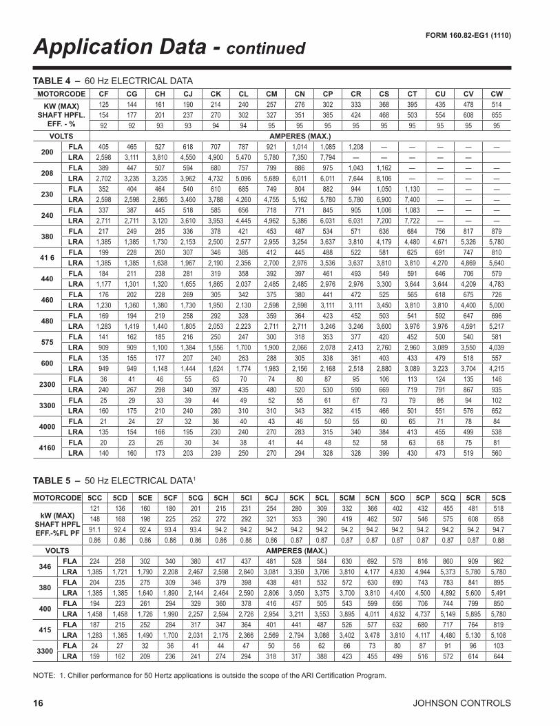
NOTE: 1. Chiller performance for 50 Hertz applications is outside the scope of the ARI Certification Program.
Application Data - continued
TABLE 5 – 50 Hz ELECTRICAL DATA1
TABLE 4 – 60 Hz ELECTRICAL DATAMOTORCODE CF CG CH CJ CK CL CM CN CP CR CS CT CU CV CW
KW (MAX)SHAFT HPFL.
EFF. - %
125 144 161 190 214 240 257 276 302 333 368 395 435 478 514154 177 201 237 270 302 327 351 385 424 468 503 554 608 65592 92 93 93 94 94 95 95 95 95 95 95 95 95 95
VOLTS AMPERES (MAX.)
200FLA 405 465 527 618 707 787 921 1,014 1,085 1,208 — — — — —LRA 2,598 3,111 3,810 4,550 4,900 5,470 5,780 7,350 7,794 — — — — —
208FLA 389 447 507 594 680 757 799 886 975 1,043 1,162 — — — —LRA 2,702 3,235 3,235 3,962 4,732 5,096 5,689 6,011 6,011 7,644 8,106 — — — —
230FLA 352 404 464 540 610 685 749 804 882 944 1,050 1,130 — — —LRA 2,598 2,598 2,865 3,460 3,788 4,260 4,755 5,162 5,780 5,780 6,900 7,400 — — —
240FLA 337 387 445 518 585 656 718 771 845 905 1,006 1,083 — — —LRA 2,711 2,711 3,120 3,610 3,953 4,445 4,962 5,386 6,031 6,031 7,200 7,722 — — —
380FLA 217 249 285 336 378 421 453 487 534 571 636 684 756 817 879LRA 1,385 1,385 1,730 2,153 2,500 2,577 2,955 3,254 3,637 3,810 4,179 4,480 4,671 5,326 5,780
41 6FLA 199 228 260 307 346 385 412 445 488 522 581 625 691 747 810LRA 1,385 1,385 1,638 1,967 2,190 2,356 2,700 2,976 3,536 3,637 3,810 3,810 4,270 4,869 5,640
440FLA 184 211 238 281 319 358 392 397 461 493 549 591 646 706 579LRA 1,177 1,301 1,320 1,655 1,865 2,037 2,485 2,485 2,976 2,976 3,300 3,644 3,644 4,209 4,783
460FLA 176 202 228 269 305 342 375 380 441 472 525 565 618 675 726LRA 1,230 1,360 1,380 1,730 1,950 2,130 2,598 2,598 3,111 3,111 3,450 3,810 3,810 4,400 5,000
480FLA 169 194 219 258 292 328 359 364 423 452 503 541 592 647 696LRA 1,283 1,419 1,440 1,805 2,053 2,223 2,711 2,711 3,246 3,246 3,600 3,976 3,976 4,591 5,217
575FLA 141 162 185 216 250 247 300 318 353 377 420 452 500 540 581LRA 909 909 1,100 1,384 1,556 1,700 1,900 2,066 2,078 2,413 2,760 2,960 3,089 3,550 4,039
600FLA 135 155 177 207 240 263 288 305 338 361 403 433 479 518 557LRA 949 949 1,148 1,444 1,624 1,774 1,983 2,156 2,168 2,518 2,880 3,089 3,223 3,704 4,215
2300FLA 36 41 46 55 63 70 74 80 87 95 106 113 124 135 146LRA 240 267 298 340 397 435 480 520 530 590 669 719 791 867 935
3300FLA 25 29 33 39 44 49 52 55 61 67 73 79 86 94 102LRA 160 175 210 240 280 310 310 343 382 415 466 501 551 576 652
4000FLA 21 24 27 32 36 40 43 46 50 55 60 65 71 78 84LRA 135 154 166 195 230 240 270 283 315 340 384 413 455 499 538
4160FLA 20 23 26 30 34 38 41 44 48 52 58 63 68 75 81LRA 140 160 173 203 239 250 270 294 328 328 399 430 473 519 560
MOTORCODE 5CC 5CD 5CE 5CF 5CG 5CH 5CI 5CJ 5CK 5CL 5CM 5CN 5CO 5CP 5CQ 5CR 5CS
kW (MAX)SHAFT HPFL EFF.-%FL PF
121 136 160 180 201 215 231 254 280 309 332 366 402 432 455 481 518148 168 198 225 252 272 292 321 353 390 419 462 507 546 575 608 65891.1 92.4 92.4 93.4 93.4 94.2 94.2 94.2 94.2 94.2 94.2 94.2 94.2 94.2 94.2 94.2 94.70.86 0.86 0.86 0.86 0.86 0.86 0.86 0.86 0.87 0.87 0.87 0.87 0.87 0.87 0.87 0.87 0.88
VOLTS AMPERES (MAX.)
346FLA 224 258 302 340 380 417 437 481 528 584 630 692 578 816 860 909 982LRA 1,385 1,721 1,790 2,208 2,467 2,598 2,840 3,081 3,350 3,706 3,810 4,177 4,830 4,944 5,373 5,780 5,780
380FLA 204 235 275 309 346 379 398 438 481 532 572 630 690 743 783 841 895LRA 1,385 1,385 1,640 1,890 2,144 2,464 2,590 2,806 3,050 3,375 3,700 3,810 4,400 4,500 4,892 5,600 5,491
400FLA 194 223 261 294 329 360 378 416 457 505 543 599 656 706 744 799 850LRA 1,458 1,458 1,726 1,990 2,257 2,594 2,726 2,954 3,211 3,553 3,895 4,011 4,632 4,737 5,149 5,895 5,780
415FLA 187 215 252 284 317 347 364 401 441 487 526 577 632 680 717 764 819LRA 1,283 1,385 1,490 1,700 2,031 2,175 2,366 2,569 2,794 3,088 3,402 3,478 3,810 4,117 4,480 5,130 5,108
3300FLA 24 27 32 36 41 44 47 50 56 62 66 73 80 87 91 96 103LRA 159 162 209 236 241 274 294 318 317 388 423 455 499 516 572 614 644

FORM 160.82-EG1 (1110)
17JOHNSON CONTROLS
*Min. reduced voltage tap 80%.** High voltage and special motor designs may not meet efficiency and P. F. shown for standard motors
CX CY CZ CA CB DA DB DC DD DE DF DH DJ DK DL MOTORCODE 542 578 617 660 703 781 859 937 1,015 1,093 1,171 1,359 1,554 1748 1942 kW (MAX.)
SHAFT HPFL EFF.-%**
690 740 790 845 900 1,000 1,100 1,200 1,300 1,400 1,500 1,750 2,000 2250 250095 95.5 95.5 95.5 95.5 95.5 95.5 95.5 95.5 95.5 95.5 96 96 96 96
AMPERES (MAX.) VOLTS— — — — — — — — — — — — — — — FLA
200 — — — — — — — — — — — — — — — LRA— — — — — — — — — — — — — — — FLA
208 — — — — — — — — — — — — — — — LRA— — — — — — — — — — — — — — — FLA
230 — — — — — — — — — — — — — — — LRA— — — — — — — — — — — — — — — FLA
240 — — — — — — — — — — — — — — — LRA
942 997 1065 1,126 1,200 1,364 1,500 1,636 — — — — — — — FLA380
6,782 5,780 6,644 7,106 7,513 7,794 8,491 9,431 — — — — — — — LRA860 911 973 1,029 1,096 1,246 1,370 1,495 — — — — — — — FLA
416 5,780 5,694 6,069 6,489 6,863 7,120 7,755 8,608 — — — — — — — LRA813 861 920 973 1,036 1,178 1,295 1,413 — — — — — — — FLA
440 5,357 4,783 5,249 5,529 5,529 6,160 6,709 7,455 — — — — — — — LRA778 824 880 931 991 1,127 1,239 1,352 — — — — — — — FLA
460 5,600 5,000 5,488 5,780 5,780 6,440 7,014 7,794 — — — — — — — LRA746 790 843 892 950 1,080 1,187 1,296 — — — — — — — FLA
480 5,843 5,217 5,727 6,031 6,031 6,720 7,319 8,133 — — — — — — — LRA622 659 704 744 793 901 991 1,081 — — — — — — — FLA
575 4,440 4,300 4,200 4,694 4,963 5,148 5,610 6,232 — — — — — — — LRA596 632 675 713 760 863 950 1,036 — — — — — — — FLA
600 4,633 4,484 4,383 4,898 5,179 5,372 5,854 6,503 — — — — — — — LRA154 165 176 186 198 225 248 267 290 312 334 389 438 493 548 FLA
2,300 960 1,008 1,100 1,172 1,230 1,234 1,592 1,592 1,592 2,031 2,031 2,390 2,879 2908 3012 LRA108 115 123 130 138 157 173 186 202 217 233 271 306 344 382 FLA
3,300 682 719 744 744 858 861 1,110 1,110 1,110 1,416 1,416 1,661 2,011 2027 2100 LRA89 95 101 107 114 130 143 154 166 179 192 224 252 283 315 FLA
4,000 540 554 631 674 713 715 923 923 923 1,177 1,177 1,386 1,669 1672 1732 LRA85 91 97 103 110 125 137 149 160 172 185 215 242 273 303 FLA
4,160 562 576 656 701 742 744 960 960 960 1,224 1,224 1,441 1,736 1608 1666 LRA
5CT 5CU 5CV 5CW 5CX 5DA 5DB 5DC 5DD 5DE 5DF 5DG 5DH *5DJ 5DK 5DL MOTORCODE 554 591 630 669 709 785 863 942 1,015 1,093 1,171 1,288 1,360 1,554 1,748 1,942 kW(MAX.)
SHAFT HPFL EFF.-%**FL
PF**
704 750 800 850 900 1,000 1,100 1,200 1,300 1,400 1,500 1,650 1,750 2,000 2,250 2,50094.7 94.7 94.7 94.7 94.7 95 95 95 95.5 95.5 95.5 95.5 96 96 96 960.88 0.89 0.89 0.89 0.89 0.88 0.87 0.88 0.88 0.88 0.88 0.88 0.89 0.89 0.89 0.89
VOLTS AMPERES (MAX.)1,051 1,107 1,181 1,255 1,329 1,488 1,656 — — — — — — — — — FLA
3466,615 6,931 7,356 7,794 8,319 8,559 9,346 — — — — — — — — — LRA957 1,008 1,075 1,143 1,210 1,355 1,508 — — — — — — — — — FLA
3805,491 6,313 6,694 7,113 7,404 7,794 8,511 — — — — — — — — — LRA909 958 1,021 1,086 1,150 1,287 1,433 — — — — — — — — — FLA
4005,780 6,645 7,046 7,487 7,794 8,204 8,959 — — — — — — — — — LRA876 923 985 1,046 1,108 1,241 1,381 — — — — — — — — — FLA
4155,512 5,780 6,131 6,513 6,938 7,138 7,794 — — — — — — — — — LRA110 116 124 132 139 156 174 187 202 217 233 256 267 306 344 382 FLA
3,300693 725 744 819 875 871 1,135 1,135 1,135 1,415 1,415 1,415 1,667 1,591 2,231 2,481 LRA
18 JOHNSON CONTROLS
FORM 160.82-EG1 (1110)
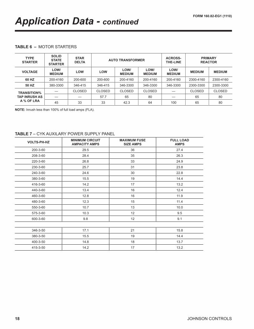
TABLE 6 – MOTOR STARTERS
Application Data - continued
NOTE: Inrush less than 100% of full load amps (FLA).
TYPESTARTER
SOLIDSTATE
STARTER
STARDELTA AUTO TRANSFORMER ACROSS-
THE-LINEPRIMARY REACTOR
VOLTAGE LOW/MEDIUM LOW LOW LOW/
MEDIUMLOW/
MEDIUMLOW/
MEDIUM MEDIUM MEDIUM
60 HZ 200-4160 200-600 200-600 200-4160 200-4160 200-4160 2300-4160 2300-4160
50 HZ 380-3300 346-415 346-415 346-3300 346-3300 346-3300 2300-3300 2300-3300
TRANSITION% TAP INRUSH AS
A % OF LRA
— CLOSED CLOSED CLOSED CLOSED — CLOSED CLOSED
— — 57.7 65 80 — 65 80
45 33 33 42.3 64 100 65 80
TABLE 7 – CYK AUXILARY POWER SUPPLY PANEL
VOLTS-PH-HZ MINIMUM CIRCUIT AMPACITY AMPS
MAXIMUM FUSE SIZE AMPS
FULL LOADAMPS
200-3-60 29.5 36 27.4
208-3-60 28.4 35 26.3
220-3-60 26.8 33 24.9
230-3-60 25.7 31 23.8
240-3-60 24.6 30 22.8
380-3-60 15.5 19 14.4
416-3-60 14.2 17 13.2
440-3-60 13.4 16 12.4
460-3-60 12.8 16 11.9
480-3-60 12.3 15 11.4
550-3-60 10.7 13 10.0
575-3-60 10.3 12 9.5
600-3-60 9.8 12 9.1
346-3-50 17.1 21 15.8
380-3-50 15.5 19 14.4
400-3-50 14.8 18 13.7
415-3-50 14.2 17 13.2

FORM 160.82-EG1 (1110)
19JOHNSON CONTROLS
Overall Chiller Arrangement
HIGH STAGECOMPRESSOR
CONDENSER
EVAPORATOR
LOW STAGECOMPRESSOR
INTERSTAGE VALVE
QUANTUMLXCONTROL
PANEL
LEVELVALVES
FLASH ECONOMIZER
(INTERCOOLER)
MOTORHIGH STAGE MOTOR
LOW STAGE HIGH STAGECOMPRESSOR DISCHARGE INTERSTAGE VALVE
HOT GASVALVE
CONDENSERLIQUID LEVELSIGHT GLASS
LOW STAGEOIL PUMPHOUSINGHIGH STAGE
OIL PUMPHOUSING
DISCHARGE CHECKVALVES
OIL COOLERWATER CONN’SLOW
STAGE OILCOOLER
HIGH STAGEOIL COOLER
FIG. 2 – CHILLER ARRANGEMENT

20 JOHNSON CONTROLS
FORM 160.82-EG1 (1110)
Compact Nozzle ArrangementsEVAPORATOR COMPACT WATER BOXES
SHELLCODES
1 Pass 2 Pass 3 Pass
Size150LB 300LB
Size150LB 300LB
Size150LB 300LB
In / Out Fig. In / Out Fig. In / Out Fig. In / Out Fig. In / Out Fig. In / Out Fig.
K 16A / H
3A / H
3 12C / B
4C / B
4 10G / N
6G / N
6H / A H / A K / J K / J P / F P / F
N, QQ, QR, QS, Q2,Q3, Q4
18A / H
7A / H
314
B / C
8
C / B4 12
F / N9
G / N6
H / A H / A C / B K / J N / F P / FJ / KK / J
QT, QV20
A / H7
A / H3
16
B / C
8
C / B4 12
F / N9
G / N6
H / A H / A C / B K / J N / F P / FJ / KK / J
R, S, W, X, Z20
A / H7
A / H3
18
B / C
8
E / B
514
F / N9
G / N6
H / A H / A C / B M / J N / F P / FJ / K D / CK / J L / K
EVAPORATOR
A
COMPRESSOR END
FRONTCONTROLCENTER
MOTOR END
H
COMPRESSOR END MOTOR END
B
C
FRONTCONTROLCENTER
COMPRESSOR END MOTOR END
J
K
FRONTCONTROLCENTER
EVAPORATOREVAPORATOR
FIG. 4 – 2 PASS
FIG. 3 – 1 PASS

FORM 160.82-EG1 (1110)
21JOHNSON CONTROLS
COMPRESSOR END MOTOR END
EVAPORATOR
D
C
FRONTCONTROLCENTER
COMPRESSOR END MOTOR END
EVAPORATOR
FRONTCONTROLCENTER
COMPRESSOR END MOTOR END
B
E
FRONTCONTROLCENTER
COMPRESSOR END MOTOR END
EVAPORATOR
FRONTCONTROLCENTER J
M
L
K
EVAPORATOR
FIG. 5 – 2 PASS
Notes:1. Standard water nozzles are Schedule 40 pipe size, furnished as welding stub-outs with ANSI/AWWA C-606 grooves, allowing the option of welding,
flanges, or use of ANSI/AWWA C-606 couplings. Factory installed, Class 150 (ANSI B16.5, round slip-on, forged carbon steel with 1/16” raised face), water flanged nozzles are optional. Companion flanges, nuts, bolts and gaskets are not furnished.
2. One, two and three pass nozzle arrangements are available only in pairs shown. Any pair of evaporator nozzles may be used in combination with any pair of condenser nozzles. Compact water boxes on one heat exchanger may be used with Marine water boxes on the other heat exchanger.
3. Water must enter the water box through the bottom connection to achieve rated performance.4. Connected piping should allow for removal of compact water boxes for tube access and cleaning.

22 JOHNSON CONTROLS
FORM 160.82-EG1 (1110)
Compact Nozzle Arrangements - continued
COMPRESSOR END MOTOR END
EVAPORATOR
N
G
FRONTCONTROLCENTER
COMPRESSOR END MOTOR END
EVAPORATOR
F
P
FRONTCONTROLCENTER
FIG. 6 – 3 PASS
A
COMPRESSOR END
FRONTCONTROLCENTER
EVAPORATOR MOTOR END
H
FIG. 7 – 1 PASS
Note: This table is repeated from the previous page for convenience only.
EVAPORATOR COMPACT WATER BOXES
SHELLCODES
1 Pass 2 Pass 3 Pass
Size150LB 300LB
Size150LB 300LB
Size150LB 300LB
In / Out Fig. In / Out Fig. In / Out Fig. In / Out Fig. In / Out Fig. In / Out Fig.
K 16A / H
3A / H
3 12C / B
4C / B
4 10G / N
6G / N
6H / A H / A K / J K / J P / F P / F
N, QQ, QR, QS, Q2,Q3, Q4
18A / H
7A / H
314
B / C
8
C / B4 12
F / N9
G / N6
H / A H / A C / B K / J N / F P / FJ / KK / J
QT, QV20
A / H7
A / H3
16
B / C
8
C / B4 12
F / N9
G / N6
H / A H / A C / B K / J N / F P / FJ / KK / J
R, S, W, X, Z20
A / H7
A / H3
18
B / C
8
E / B
514
F / N9
G / N6
H / A H / A C / B M / J N / F P / FJ / K D / CK / J L / K

FORM 160.82-EG1 (1110)
23JOHNSON CONTROLS
EVAPORATOR
COMPRESSOR END MOTOR END
B C
FRONTCONTROLCENTER
EVAPORATOR
COMPRESSOR END MOTOR END
FRONTCONTROLCENTER
J K
FIG. 8 – 2 PASS
FIG. 9 – 3 PASS
F
COMPRESSOR END
FRONTCONTROLCENTER
EVAPORATOR MOTOR END
N
Notes:1. Standard water nozzles are Schedule 40 pipe size, furnished as welding stub-outs with ANSI/AWWA C-606 grooves, allowing the option of welding,
flanges, or use of ANSI/AWWA C-606 couplings. Factory installed, Class 150 (ANSI B16.5, round slip-on, forged carbon steel with 1/16” raised face), water flanged nozzles are optional. Companion flanges, nuts, bolts and gaskets are not furnished.
2. One, two and three pass nozzle arrangements are available only in pairs shown. Any pair of evaporator nozzles may be used in combination with any pair of condenser nozzles. Compact water boxes on one heat exchanger may be used with Marine water boxes on the other heat exchanger.
3. Water must enter the water box through the bottom connection to achieve rated performance.4. Connected piping should allow for removal of compact water boxes for tube access and cleaning.
24 JOHNSON CONTROLS
FORM 160.82-EG1 (1110)
Compact Nozzle Arrangements - continued
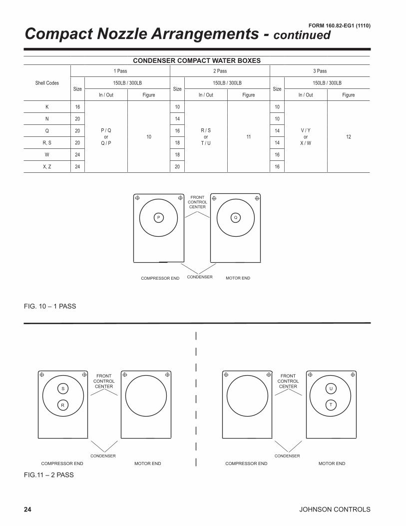
COMPRESSOR END
FRONTCONTROLCENTER
CONDENSER MOTOR END
P Q
COMPRESSOR END MOTOR END
CONDENSER
FRONTCONTROLCENTERS
R
COMPRESSOR END MOTOR END
CONDENSER
U
T
FRONTCONTROLCENTER
FIG. 10 – 1 PASS
FIG.11 – 2 PASS
CONDENSER COMPACT WATER BOXES
Shell Codes
1 Pass 2 Pass 3 Pass
Size150LB / 300LB
Size150LB / 300LB
Size150LB / 300LB
In / Out Figure In / Out Figure In / Out Figure
K 16
P / Qor
Q / P10
10
R / Sor
T / U11
10
V / Yor
X / W12
N 20 14 10
Q 20 16 14
R, S 20 18 14
W 24 18 16
X, Z 24 20 16
FORM 160.82-EG1 (1110)
25JOHNSON CONTROLS
COMPRESSOR END MOTOR END
CONDENSER
FRONTCONTROLCENTER
COMPRESSOR END MOTOR END
CONDENSER
FRONTCONTROLCENTERY
V
W
X
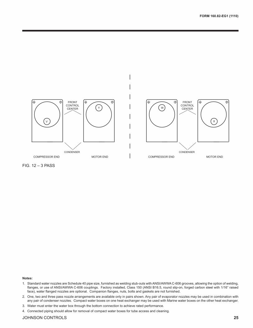
FIG. 12 – 3 PASS
Notes:1. Standard water nozzles are Schedule 40 pipe size, furnished as welding stub-outs with ANSI/AWWA C-606 grooves, allowing the option of welding,
flanges, or use of ANSI/AWWA C-606 couplings. Factory installed, Class 150 (ANSI B16.5, round slip-on, forged carbon steel with 1/16” raised face), water flanged nozzles are optional. Companion flanges, nuts, bolts and gaskets are not furnished.
2. One, two and three pass nozzle arrangements are available only in pairs shown. Any pair of evaporator nozzles may be used in combination with any pair of condenser nozzles. Compact water boxes on one heat exchanger may be used with Marine water boxes on the other heat exchanger.
3. Water must enter the water box through the bottom connection to achieve rated performance.4. Connected piping should allow for removal of compact water boxes for tube access and cleaning.

26 JOHNSON CONTROLS
FORM 160.82-EG1 (1110)
Marine Nozzle ArrangementsEVAPORATOR MARINE WATER BOXES
Shell Codes1 Pass 2 Pass 3 Pass
Size150 LB / 300 LB
Size150 LB / 300 LB
Size150 LB / 300 LB
In / Out Figure In / Out Figure In / Out FigureK 16
1 / 6or
6 / 113
12
2 / 3or
7 / 814
10
5 / 10or
9 / 415
N, QQ, QR, QS, Q2, Q3, Q4 18 14 12
QT, QV 20 16 12R, S, W, X, Z 20 18 14
COMPRESSOR END
FRONTCONTROLCENTER
MOTOR END
1 6
EVAPORATOR
FIG. 14 – 2 PASS
FIG. 13 – 1 PASS
COMPRESSOR END MOTOR END
FRONTCONTROLCENTER
COMPRESSOR END MOTOR END
FRONTCONTROLCENTER
EVAPORATOREVAPORATOR
3
2
8
7

FORM 160.82-EG1 (1110)
27JOHNSON CONTROLS
FIG. 15 – 3 PASS
COMPRESSOR END MOTOR END
FRONTCONTROLCENTER
COMPRESSOR END MOTOR END
FRONTCONTROLCENTER
EVAPORATOREVAPORATOR
5
4
9
10
Notes:1. Standard water nozzles are Schedule 40 pipe size, furnished as welding stub-outs with ANSI/AWWA C-606 grooves, allowing the option of welding,
flanges, or use of ANSI/AWWA C-606 couplings. Factory installed, Class 150 (ANSI B16.5, round slip-on, forged carbon steel with 1/16” raised face), water flanged nozzles are optional. Companion flanges, nuts, bolts and gaskets are not furnished.
2. One, two and three pass nozzle arrangements are available only in pairs shown. Any pair of evaporator nozzles may be used in combination with any pair of condenser nozzles. Compact water boxes on one heat exchanger may be used with Marine water boxes on the other heat exchanger.
3. Water must enter the water box through the bottom connection to achieve rated performance.4. Connected piping should allow for removal of compact water boxes for tube access and cleaning.
28 JOHNSON CONTROLS
FORM 160.82-EG1 (1110)
COMPRESSOR END
FRONTCONTROLCENTER
CONDENSER MOTOR END
11 16
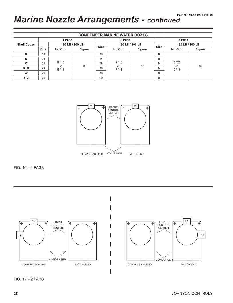
FIG. 16 – 1 PASS
CONDENSER MARINE WATER BOXES
Shell Codes1 Pass 2 Pass 3 Pass
150 LB / 300 LBSize
150 LB / 300 LBSize
150 LB / 300 LBSize In / Out Figure In / Out Figure In / Out Figure
K 16
11 / 16 or
16 / 1116
10
12 / 13or
17 / 1817
10
15 / 20 or
19 / 1418
N 20 14 10Q 20 16 14
R, S 20 18 14W 24 18 16
X, Z 24 20 16
COMPRESSOR END MOTOR END
FRONTCONTROLCENTER
COMPRESSOR END MOTOR END
FRONTCONTROLCENTER
18
17
CONDENSER CONDENSER
P
13
12
FIG. 17 – 2 PASS
Marine Nozzle Arrangements - continued

FORM 160.82-EG1 (1110)
29JOHNSON CONTROLS
COMPRESSOR END MOTOR END
FRONTCONTROLCENTER
COMPRESSOR END MOTOR END
FRONTCONTROLCENTER
CONDENSERCONDENSER
20 14
1915
FIG. 18 – 3 PASS
Notes:1. Standard water nozzles are Schedule 40 pipe size, furnished as welding stub-outs with ANSI/AWWA C-606 grooves, allowing the option of welding,
flanges, or use of ANSI/AWWA C-606 couplings. Factory installed, Class 150 (ANSI B16.5, round slip-on, forged carbon steel with 1/16” raised face), water flanged nozzles are optional. Companion flanges, nuts, bolts and gaskets are not furnished.
2. One, two and three pass nozzle arrangements are available only in pairs shown. Any pair of evaporator nozzles may be used in combination with any pair of condenser nozzles. Compact water boxes on one heat exchanger may be used with Marine water boxes on the other heat exchanger.
3. Water must enter the water box through the bottom connection to achieve rated performance.4. Connected piping should allow for removal of compact water boxes for tube access and cleaning.

30 JOHNSON CONTROLS
FORM 160.82-EG1 (1110)
GENERAL
Furnish and install where indicated on the drawings____YORK model CYK Compound Centrifugal Compressor Liquid Chilling Unit(s). Each unit shall produce a capacity of ____ tons, cooling ____ GPM of ____ from ____ °F to ____ °F when supplied with ____ GPM of condenser water at ____ °F. Total power input (two motors) shall not exceed ____ kW. The evaporator shall be selected for____ fouling factor and a maximum liquid pressure drop of ____ ft. Water side shall be designed for 150 psig working pressure. The condenser shall be selected for ____ fouling factor and maximum liquid pressure drop of ____ ft. Waterside shall be designed for 150 psig working pressure. Power shall be supplied to the compressor drive motors at ____ volts – 3-phase – (60)(50) Hertz. Auxiliary power to the oil pump motors and controls shall be sup-plied at___ volts – 3-phase – (60)(50) Hertz
(or)
Furnish and install where indicated on the drawings ___YORK model CYK Compound Centrifugal Compres-sor Heat Pump Unit(s). Each unit shall produce a capacity of ____ tons, heating ____ GMP of ____ from ____ °F to ____ °F when supplied with ____ GPM of evaporator water at ____°F. Total power input (two motors) shall not exceed ____ kW. The evaporator shall be selected for ____ ft. fouling factor and maximum liquid pressure drop of ____ ft. Waterside shall be designed for 150 psig working pressure. The condenser shall be selected for ____ ft. fouling factor and maximum liquid pressure drop of ____ kPa. Waterside shall be designed for 150 psig working pressure.
(or)
Furnish and install where indicated on the drawings ___YORK model CYK Compound Centrifugal Compressor Liquid Chilling Unit(s). Each unit shall produce a capac-ity of ____ kW, cooling ____ L/S of ____ from ____ °C to ____ °C when supplied with ____ L/S of condenser water at ____°C. Total power input (two motors) shall not exceed ____ kW. The evaporator shall be selected for ____m2°C/W fouling factor and maximum liquid pressure drop of ____barg. Waterside shall be designed for 10.3 barg working pressure. The condenser shall be selected for ____ m2°C/W fouling factor and maximum liquid pres-sure drop of ____ barg. Waterside shall be designed for 10.3 barg working pressure.
Power shall be supplied to the compressor drive motors at ____ volts – 3-phase – (60)(50) Hertz. Auxiliary power to the oil pump motors and controls shall be supplied at ___ volts - 3-phase – (60)(50) Hertz.
(or)
Furnish and install where indicated on the drawings ___YORK model CYK Compound Centrifugal Compres-sor Heat Pump Unit(s). Each unit shall produce a capac-ity of ____ kW, heating ____ L/S of ____ from ____ °C to ____ °C when supplied with ____ L/S of evaporator water at ____°C. Total power input (two motors) shall not exceed ____ kW. The evaporator shall be selected for ____m2°C/W fouling factor and maximum liquid pressure drop of ____kPa. Waterside shall be designed for 10.3 barg working pressure. The condenser shall be selected for ____ m2°C/W fouling factor and maximum liquid pres-sure drop of ____ kPa. Waterside shall be designed for 10.3 barg working pressure.
Each unit shall be completely factory-packaged includ-ing evaporator, condenser, sub-cooler, compressors, flash economizer (intercooler), open motors, lubrication system, Control Center, and all interconnecting unit pip-ing and wiring. The economizer is removed for shipment. Flanged joints are provided and all piping is prefabricated. The chiller shall be painted prior to shipment. The initial charge of oil and refrigerant shall be supplied, shipped in containers and cylinders for field installation or factory charged in the chiller when possible.
COMPRESSORS
Two centrifugal compressors shall be provided, operating in series and using a common refrigerant circuit on the chiller. Check valves will be supplied on the discharge of the low and high stage compressors to control refrigerant flow during single compressor low head operation and two compressor high head operation.
Each compressor shall be a single-stage centrifugal type, powered by an open-drive electric motor. The housing shall be fully accessible with vertical circular joints, with the complete operating assembly removable from the compressor and scroll housing. Compressor castings on the low stage shall be designed for a minimum 235 psig (16.2 barg) working pressure and hydrostatically pres-sure tested at a minimum of 352 psig (24.3 barg). The high stage shall be designed for 235 or 350 psig (16.2 or 24.1 barg) as applicable, and hydrostatically pressure tested at a minimum of 1.3 times the design pressure. The rotor assembly shall consist of a heat-treated alloy steel drive shaft and impeller shaft with a cast aluminum, fully shrouded impeller. The impeller shall be designed for balanced thrust, dynamically balanced and over-speed tested for smooth, vibration-free operation. Insert-type journal and thrust bearings shall be fabricated of aluminum alloy, precision bored and axially grooved.
Guide Specifications

FORM 160.82-EG1 (1110)
31JOHNSON CONTROLS
Internal single helical gears with crowned teeth shall be designed so that more than one tooth is in contact at all times to provide even load distribution and quiet operation. Each gear shall be individually mounted in its own journal and thrust bearings to isolate it from impeller and motor forces. Shaft seal shall be provided in double bellows, double-seal, cartridge type. A gravity-fed oil reservoir shall be built into the top of the compressor to provide lubrica-tion during coast-down in the event of a power failure.
Capacity control shall be achieved by use of pre-rotation vanes to provide fully modulating control from full load to minimum load. Control shall automatically compensate for adverse operating conditions, such as fouled tubes, and adjust to prior operation after correction of these condi-tions. The unit shall be capable of continuous, reliable operation with low ECWT at all load conditions as outlined on the equipment schedule. An external electric actuator shall automatically control pre-rotation vane position for each compressor.
LUBRICATION SYSTEM
Lubrication oil shall be force-fed to all compressor bear-ings, gears, and rotating surfaces by variable speed oil pumps mounted in individual oil reservoirs. Each oil pump shall vary oil flow to its compressor based on operating and stand-by conditions, ensuring adequate lubrication at all times. The oil pump shall operate prior to start-up, during compressor operation and during coast-down.
Dual oil reservoirs, separate from the compressors, shall contain the 2 HP submersible oil pumps and 1500 watt immersion-type oil heaters for each compressor. The oil heaters shall be thermostatically controlled to remove re-frigerant from the oil. The oil reservoirs shall be designed and stamped in accordance with ASME pressure vessel code. A non-code reservoir is not acceptable.
Water-cooled oil coolers shall be provided after each oil pump, with factory installed water piping. A thermostati-cally controlled bypass valve shall maintain the required oil temperature supply from each oil cooler to its compressor.
Oil shall be filtered by externally mounted, 1/2 micron, re-placeable cartridge oil filters, equipped with service valves. An automatic oil return system to recover any oil that may have migrated to the evaporator shall be provided. Oil piping shall be completely factory installed and tested.
MOTOR DRIVELINE
Each compressor motor shall be an open drip-proof, squir-rel cage, induction type operating at 3570 rpm (2975 rpm for 50 Hz operation).
Each open motor shall be provided with a D-flange, bolted to a cast iron adaptor mounted on the compressor to al-low the motor to be rigidly coupled to the compressor to provide factory alignment of motor and compressor shafts.Each motor drive shaft shall be directly connected to its compressor shaft with a flexible disc coupling.The cou-pling shall have all metal construction with no wearing parts to assure long life, and no lubrication requirements to provide low maintenance. A large steel terminal box with gasketed front access cover shall be provided for field-connected conduit.
EVAPORATOR
Evaporator shall be of the shell-and-tube, flooded type designed for a minimum of 180 psig (12.4 barg) working pressure on the refrigerant side. Shell shall be fabricated from rolled carbon steel plates with fusion welded seams, carbon steel tube sheets, drilled and reamed to accom-modate the tubes, and intermediate tube supports spaced no more than four feet apart. The refrigerant side of each shell is designed, tested and stamped in accordance with ASME Boiler and Pressure Vessel Code, Section VIII – Division I.
Heat exchanger tubes shall be high-efficiency, externally and internally enhanced type. Tubes shall utilize the “skip-fin” design, providing a smooth internal and external surface at each intermediate tube support. This provides extra wall thickness and non-work hardened copper at the support location, extending the life of the heat exchangers. If skip-fin tubes are not used, minimum tube wall thick-ness shall be 0.035” (0.889 mm). Each tube shall be roller expanded into the tube sheets providing a leak-proof seal, and be individually replaceable. Water velocity through the tubes shall not exceed 12 ft./sec. (3.65 m/sec). A liq-uid level sight glass shall be provided on the side of the shell to aid in determining proper refrigerant charge and to check condition of the refrigerant charge. Aluminum mesh eliminators or baffles shall be located above the tube bundle to prevent liquid refrigerant carryover to the compressor. The evaporator shall have a refrigerant relief device sized to meet the requirements of the ASHRAE 15 Safety Code for Mechanical Refrigeration.
Water boxes shall be removable to permit tube cleaning and replacement. Stub-out water connections having ANSI/AWWA C-606 grooves shall be provided. Water boxes shall be designed for 150 psig (10.3 barg) design working pressure and be tested at 225 psig (15.5 barg). Vent and drain connections with plugs shall be provided on each water box. Low flow protection shall be provided by a thermal-type flow sensor, factory mounted in the water nozzle connection and wired to the chiller panel.

32 JOHNSON CONTROLS
FORM 160.82-EG1 (1110)
CONDENSER
Condenser shall be of the shell-and-tube type, designed for a minimum of 235 psig (16.2 barg) working pressure on the refrigerant side. Shell shall be fabricated from rolled carbon steel plates with fusion welded seams. Carbon steel tube sheets, drilled and reamed to accommodate the tubes, are welded to the end of each shell. Intermediate tube supports are drilled and reamed to eliminate sharp edges, fabricated from carbon steel plates. The refriger-ant side of each shell is designed, tested and stamped in accordance with ASME Boiler and Pressure Vessel Code, Section VIII – Division I.
Heat exchanger tubes shall be high efficiency, exter-nally and internally enhanced type. Tubes shall utilize the “skip-fin” design, providing a smooth internal and external surface at each intermediate tube support. This provides extra wall thickness and non-work hardened copper at the support location, extending the life of the heat exchangers. If skip-fin tubes are not used, minimum tube wall thickness shall be 0.035” (0.889 mm). Each tube shall be roller expanded into the tube sheets providing a leak-proof seal, and be individually replaceable. Water velocity through the tubes shall not exceed 12 ft./sec. (3.65 m/sec.). A liquid level sight glass shall be provided on the side of the shell to aid in determining proper refrigerant charge and to check condition of the refrigerant charge. The condenser shall have dual refrigerant relief devices; each sized to meet the requirements of the ASHRAE 15 Safety Code for Mechanical Refrigeration. Arrangement shall allow either valve to be isolated and replaced without removing the unit refrigerant charge.
Water boxes shall be removable to permit tube cleaning and replacement. Stub-out water connections having ANSI/AWWA C-606 grooves shall be provided. Water boxes shall be designed for 150 psig (1034 barg) design working pressure and be tested at 225 psig (1551 barg). Vent and drain connections with plugs shall be provided on each water box. A thermal-type water flow sensor shall provide low flow protection, factory mounted in the water nozzle connection and wired to the chiller control panel.
FLASH ECONOMIZER (INTERCOOLER)
A single stage flash economizer (intercooler) shall be provided with internally mounted mesh eliminators, liquid spray pipe, an externally mounted (field installed) level transmitter and an external control valve. Economizer shall include eight sight glasses, two above and two below the mesh eliminators, two at the liquid spray pipe and two in liquid line leaving the economizer. A thermometer well shall be furnished for checking liquid temperature. Con-nections and field installed pressure transmitter and relief valve assemblies shall be provided for field installation.
Support legs of structural steel tubing shall be provided with mounting brackets for optional spring type isolators.
CONTROL CENTER
General – The chiller is controlled by a stand-alone QuantumLX microprocessor based control center with Linux operating system (a PLC control center is provided for Dual Evaporator CYK). The chiller control panel shall provide control of chiller operation and monitoring of chiller sensors, actuators, relays and switches. The chiller panel shall provide capacity control operation of the two series compressors in reponse to low entering condenser water and start-up requirements. The panel shall also allow the chiller to operate down to 0% evaporator load.
Control Panel – The control panel shall include a 10.4” color active matrix display with integral keypad and touch-screen for operator interface. The control panel shall be factory wired, unit mounted, Nema 12, gasketed enclo-sure. The panel shall be fabricated of 10 gauge steel and include full height front access door. The panel enclosure shall be painted to match the chiller color. All controls are arranged for easy access and internally wired to clearly marked terminal strips wiring connections. Wiring shall be color-coded black (power), red (control), light-blue and green (ground), with each wire numerically identified at both ends with wire markers. Wiring enclosed in shielded cables and pre-wired cables shall be color coded per the wiring diagram.
The screen shall detail all operations and parameters, using a graphical representation of the chiller and its components. Graphic screens shall provide for: a. Chiller Overview b. Evaporator c. Condenser d. Low stage compressor e. High stage compressor f. Motors g. Capacity control diagram h. Manual/Auto stations for all control outputs
The operator interface shall be programmed to provide display of all major operating parameters in both graphical and list type screen displays. PID control loop set points, and Manual/Auto functions shall be accomplished by the operator interface. Alarm indicators on the graphic display screen shall provide annunciation, and an alarm history screen to which show the most recent alarms, with the time and date of occurrence. Trip status screens shall be provided which show the values of all analog inputs at the time of the last 128 chiller safety shutdowns. The time
Guide Specifications - continued

FORM 160.82-EG1 (1110)
33JOHNSON CONTROLS
and date of the shutdown should also be shown. Function Keys shall be provided on the control panel for Chiller Start, Stop, Reset and Emergency Stop.
The QuantumLX control system can be accessed remotely by any internet browser, when it is incorporated into an ethernet network. This virtual operator interface allows quick access to the chillers for full remote management without having to create a separate SCADA or supervi-sory control.
CAPACITY CONTROLS SYSTEM
The Capacity Control philosophy of the chiller control system shall allow efficient fully automated control, without need for operator intervention. This control system shall monitor and display all safety aspects of the chiller and provide alarms and a shutdown if safety limits are exceeded. If operator intervention is required, manual controls shall be provided on the electronic operator interface, for all electric actuators.
The capacity controls algorithm shall automatically seek out the most efficient operation of the chiller. The pre-rotation vanes are automated to obey the temperature controller to maintain chilled water production. In cases of low load, the pre-rotation vanes shall automatically throttle and be limited to a minimum anti-surge position. To provide light duty opera-tion, the hot gas recycle valve shall be seamlessly throttled open according to temperature demands. This keeps the centrifugal compressor out of surge and maintains chilled water production.
In cases of high load, which exceeds the motor kilowatt (or current) usage, the capacity controls algorithm shall automatically unload the system to maintain a restriction on power consumption. In the same way, conditions of high discharge pressure or low suction pressure shall override the production of chilled water in the interests of keeping the chiller system online.
In cases of light load and low head, the high stage compres-sor shall be dropped offline, the flash economizer bypassed, and the unit will be run with the low stage compressor like a normal single-compressor chiller.
Analog Input List:
1. Low Stage Motor Current (% FLA) 2. High Stage Motor Current (% FLA) 3. Subcooler Refrigerant Liquid Level 4. Low Stage Oil Reservoir Oil Level (Brine Units) 5. High Stage Oil Reservoir Oil Level (Brine Units) 6. Evaporator Refrigerant Pressure
7. Condenser Refrigerant Pressure 8. Low Stage Compressor Low Oil Pressure 9. Low Stage Compressor High Oil Pressure 10. High Stage Compressor Low Oil Pressure 11. High Stage Compressor High Oil Pressure 12. Chilled Water-Out Temperature. 13. Chilled Water-In Temperature. 14. Condenser Water In Temperature 15. Condenser Water Out Temperature 16. Evaporator Refrigerant Liquid Temp. 17. Low Stage Compressor Refrigerant Discharge Tem-
perature 18. High Stage Compressor Refrigerant Discharge Tem-
perature 19. Subcooled Refrigerant Liquid Temperature 20. Low Stage Compressor Oil Temperature 21. High Stage Compressor Oil Temperature 22. Low Stage PRV Position 23. High Stage PRV Position 24. Low Stage Compressor high stage thrust Bearing
Probe Gap 25. High Stage Compressor thrust bearing Probe gap 26. Flash Economizer Pressure 27. Flash Economizer Refrigerant Liquid Level
Digital Inputs:
1 . Chilled Water Low Flow Switch 2. Condenser Water Low Flow Switch 3. Low Stage Motor Starter Full Voltage (Run) Auxiliary
Contact 4. High Stage Motor Starter Full Voltage (Run) Auxiliary
Contact5. Low Stage Motor Starter Safety Fault Lockout Relay6. High Stage Motor Starter Safety Fault Lockout Relay7. Condenser Refrigerant High Pressure Cutout8. Low Stage Compressor Oil Heater Thermostat9. High Stage Compressor Oil Heater Thermostat 10. Low Stage PRV Closed Limit Switch 11. High Stage PRV Closed Limit Switch 12. Low Stage Compressor V.S. Oil Pump Drive Faulted
Contact 13. High Stage Compressor V.S. Oil Pump Drive Faulted
Contact 14. Optional Remote Chiller Start Input 15. Emergency Stop

34 JOHNSON CONTROLS
FORM 160.82-EG1 (1110)
OptiSound inputs (when available)
1. LS VGD Position2. LS VGD Stall Sensor3. HS VGD Position4. HS VGD Stall Sensor
Analog Output List
1. Hot Gas Bypass Valve 2. Low Stage Compressor, V.S. Oil Pump Drive Control 3. High Stage Compressor, V.S. Oil Pump Drive Control 4. High Pressure Variable Orifice Valve LCV-114 5. Low Pressure Variable Orifice Valve LCV-1166. Bypass Level Control valve output LCV-117
Digital Output List 1. Low Stage Liquid Line Solenoid Valve 2. High Stage Liquid Line Solenoid Valve 3. High Stage Oil Return Solenoid (brine units only)4. Low Stage Oil Return Solenoid Valve 5. Low Stage Compressor Oil Heater Contactor 6. High Stage Compressor Oil Heater Contactor 7. Low Stage Compressor Motor Start/Stop Control Relay 8. High Stage Compressor Motor Start/Stop Control
Relay 9. Low Stage Compressor Oil Pump Start/Stop Relay 10. High Stage Compressor Oil Pump Start/Stop Relay 11. Oil Level Control Pump Start/Stop Relay (brine units
only) 12. Open Low Stage PRV 13. Open High Stage PRV 14. Close Low Stage PRV 15. Close High Stage PRV16. Interstage Sideload Valve
Optisound Control Outputs (when available)
1. Open Low Stage VGD2. Close Low Stage VGD3. Open High Stage VGD4. Close Hgh Stage VGD
Security
Security access to prevent unauthorized change of set-points, to allow local or remote control of the chiller, and
to allow manual operation of the pre-rotation vanes and oil pump shall be provided. Access shall be through ID and password recognition, which is defined by three dif-ferent levels of user experience: operator, service and programming.
OVER-CURRENT PROTECTION
The Variable Speed Oil Pump Panel shall include a fused connection through a transformer to provide individual over-current protected power for all controls.
PLANT MANAGEMENT/CONTROL SYSTEM INTER-FACE:
Ethernet is the preferred LAN (Local Area Network) be-tween Local Chiller Control Panels. Ethernet allows full management of the QuantumLX system from a central location.
The QuantumLX control system can be accessed remotely by any internet browser, when it is incorporated into an ethernet network. This virtual operator interface allows quick access to the chillers for full remote management without having to create a separate SCADA or supervi-sory control.
All required analog and discrete data for communica-tions will be arranged in blocks of 16-bit words. All data is available remotely as read only values. The following write-able control signals are available. Remote Start, Remote Stop, Remote Leaving Chilled Water Setpoint, and Remote Demand Limit Setpoint.
Available Network ProtocolsAny protocol/media requirements not listed here must be called out on the factory order form.
Available protocols will be implemented with a Johnson Controls eLink module* or RedLion Data Station where applicable:
• Modbus RTU over RS-485**• BACnet MS/TP*• BACnet/IP*• Profibus**• Allen-Bradley DH-485
Guide Specifications - continued
TABLE 8 - AVAILABLE NETWORK PROTOCOLSMedia Protocol
Cat-5 twisted pair Ethernet Industrial Protocol and Modbus TCPwww.ethernet-ip.org
RS-232 Allen-Bradley DF1 Full DuplexRS-232 Modbus RTU Slave/ASCii Slave
FORM 160.82-EG1 (1110)
35JOHNSON CONTROLS
Check appropriate protocol and include this docu-ment attached to the Factory Order Form.
All communication interface wiring and hardware, which is required external to the chiller control panel, will be supplied and installed by the electrical installation contractor under another contract.
REMOTELY MOUNTED COMPRESSOR MOTOR-STARTER (OPTION)
A remotely mounted starter shall be furnished for each compressor motor. The starter shall be furnished in accor-dance with the chiller manufacturer’s starter specifications R-1177, and as specified elsewhere in these specifica-tions. A unit-mounted solid state compressor motor starter is available as an option.
PORTABLE REFRIGERANT STORAGE / RECY-CLING SYSTEM (OPTION)
A portable, self-contained refrigerant storage/recycling system shall be provided consisting of a refrigerant com-pressor with oil separator, storage receiver, water-cooled condenser, filter drier and necessary valves and hoses to remove, replace and distill refrigerant. All necessary controls and safety devices shall be a permanent part of the system.

SI Metric ConversionValues provided in this manual are in the English inch-pound (I-P) system. The following factors can be used to convert from English to the most common Sl Metric values.
TEMPERATURE
To convert degrees Fahrenheit (°F) to degrees Celsius (°C), subtract 32° and multiply by 5/9 or 0.5556.
To convert a temperature range (i.e., 10°F or 12°F chilled water range) from Fahrenheit to Celsius, multiply by 5/9 or 0.5556. EFFICIENCY
In the English l-P system, chiller efficiency is measured in kW / ton:kW / ton = kW input tons refrigerant effect
In the Sl Metric system, chiller efficiency is measured in Coefficient of Performance (COP).
COP = kW refrigeration effect kW input
kW / ton and COP are related as follows:
kW/ton = 3.516 COP
COP = 3.516 kW/ton
10
ENGLISH l-P EQUIVALENT Sl METRIC(fl2 °F hr/Btu) (m2 k/kW)
0.0001 .0180.00025 .0440.0005 .0880.00075 .132
FOULING FACTOR
MEASUREMENTMULTIPLY THIS
ENGLISH VALUE BYTO OBTAIN THISMETRIC VALUE
CAPACITYTONS REFRIGERANT EF-
FECT (ton)3.516 KILOWATTS (kW)
POWERKILOWATTS (kW) NO CHANGE KILOWATTS (kW)
HORSEPOWER (hp) 0.7457 KILOWATTS (kW)FLOW RATE GALLONS / MINUTE (gpm) 0.0631 LITERS / SECOND (L/s)
LENGTHFEET (ft) 304.8 MILLIMETERS (mm)
INCHES (in) 25.4 MILLIMETERS (mm)WEIGHT POUNDS (lb) 0.4536 KILOGRAMS (kg)
VELOCITY FEET / SECOND (fps) 0.3048 METERS / SECOND (m/s)
PRESSURE DROPFEET OF WATER (ft) 2.989 KILOPASCALS (k Pa)
POUNDS / SQ. INCH (psi) 6.895 KILOPASCALS (k Pa)
Form 160.82-EG1 (1110) Supersedes:160.82-EG1 (409)