model yk (style h) centrifugal liquid chillers
TRANSCRIPT
Form Number: 160.76-N1 (921)
Supersedes: 160.76-N1 (721)
Installation Guide
Issue Date: 2021-09-30
Model YK (Style H) Centrifugal LiquidChillersR-134a, R-513A, or R-1234ze with OptiView Control Centerfor Electromechanical Starter, Solid State Starter, andVariable Speed Drive

2 Model YK (Style H) Centrifugal Liquid Chillers
ContentsContentsGeneral safety instructions............................................................................................................................. 5Introduction...................................................................................................................................................... 8
Field assembled units only................................................................................................................... 8Shipment.................................................................................................................................................9Inspection, damage, shortage........................................................................................................... 11Chiller data plate..................................................................................................................................12Long-term storage...............................................................................................................................12Rigging.................................................................................................................................................. 15Location................................................................................................................................................ 16Motors...................................................................................................................................................16Foundation........................................................................................................................................... 17Clearance.............................................................................................................................................. 17
Installation...................................................................................................................................................... 21Rigging unit to final location.............................................................................................................. 21Locating and installing isolator pads................................................................................................ 21Checking the isolation pad deflection...............................................................................................21Leveling the unit.................................................................................................................................. 21Installing optional spring isolators....................................................................................................21Piping connections.............................................................................................................................. 22Evaporator and condenser water piping..........................................................................................22Unit piping............................................................................................................................................ 24Refrigerant relief piping......................................................................................................................24Control panel positioning................................................................................................................... 26Control wiring.......................................................................................................................................26Power wiring........................................................................................................................................ 27Oil pump – three-phase starter..........................................................................................................27Insulation..............................................................................................................................................28Installation check – request for start-up service............................................................................. 28Compressor units................................................................................................................................ 33Evaporator compact waterboxes.......................................................................................................38Condenser compact waterboxes....................................................................................................... 42Condenser heat recovery compact waterboxes.............................................................................. 45Evaporator marine waterboxes......................................................................................................... 46Condenser marine waterboxes..........................................................................................................49Weights................................................................................................................................................. 52
Unit conversion...............................................................................................................................................55
Model YK (Style H) Centrifugal Liquid Chillers 3

4 Model YK (Style H) Centrifugal Liquid Chillers
General safety instructionsImportant: Read before proceeding.
This equipment is a relatively complicated apparatus. During installation, operation maintenance orservice, individuals may be exposed to certain components or conditions including, but not limitedto: refrigerants, materials under pressure, rotating components, and both high and low voltage.Each of these items has the potential, if misused or handled improperly, to cause bodily injury ordeath. It is the obligation and responsibility of operating/service personnel to identify and recognizethese inherent hazards, protect themselves, and proceed safely in completing their tasks. Failure tocomply with any of these requirements could result in serious damage to the equipment and theproperty in which it is situated, as well as severe personal injury or death to themselves and peopleat the site.This document is intended for use by owner-authorized rigging, installation, and operating/servicepersonnel. It is expected that these individuals possess independent training that enables themto perform their assigned tasks properly and safely. It is essential that, prior to performing anytask on this equipment, this individual shall have read and understood the on-product labels, thisdocument and any referenced materials. This individual shall also be familiar with and complywith all applicable industry and governmental standards and regulations pertaining to the task inquestion.
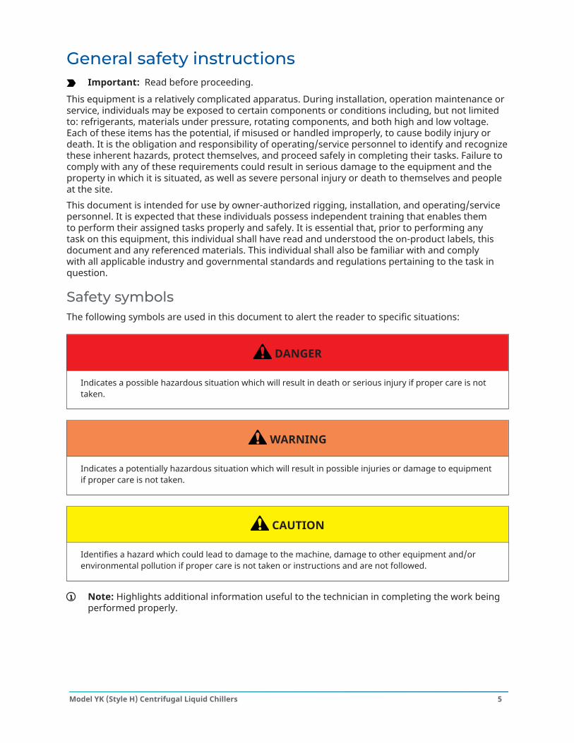
Safety symbolsThe following symbols are used in this document to alert the reader to specific situations:
DANGER
Indicates a possible hazardous situation which will result in death or serious injury if proper care is nottaken.
WARNING
Indicates a potentially hazardous situation which will result in possible injuries or damage to equipmentif proper care is not taken.
CAUTION
Identifies a hazard which could lead to damage to the machine, damage to other equipment and/orenvironmental pollution if proper care is not taken or instructions and are not followed.
Note: Highlights additional information useful to the technician in completing the work beingperformed properly.
5Model YK (Style H) Centrifugal Liquid Chillers
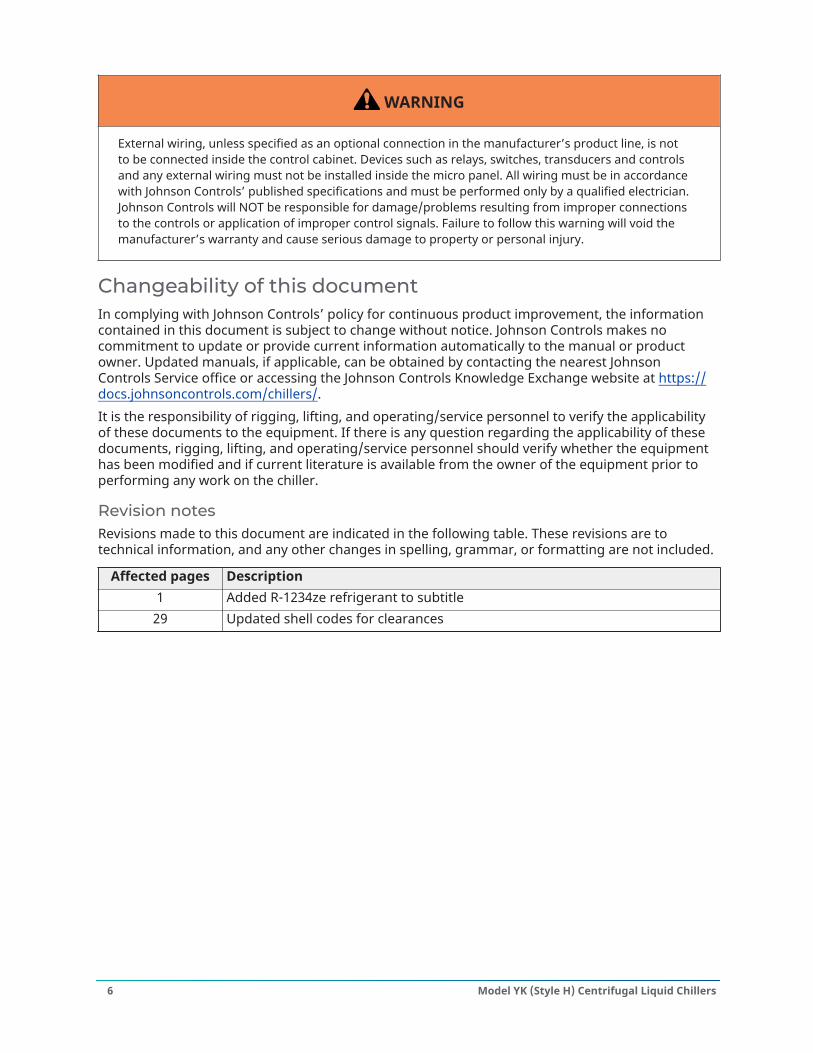
WARNING
External wiring, unless specified as an optional connection in the manufacturer’s product line, is notto be connected inside the control cabinet. Devices such as relays, switches, transducers and controlsand any external wiring must not be installed inside the micro panel. All wiring must be in accordancewith Johnson Controls’ published specifications and must be performed only by a qualified electrician.Johnson Controls will NOT be responsible for damage/problems resulting from improper connectionsto the controls or application of improper control signals. Failure to follow this warning will void themanufacturer’s warranty and cause serious damage to property or personal injury.
Changeability of this documentIn complying with Johnson Controls’ policy for continuous product improvement, the informationcontained in this document is subject to change without notice. Johnson Controls makes nocommitment to update or provide current information automatically to the manual or productowner. Updated manuals, if applicable, can be obtained by contacting the nearest JohnsonControls Service office or accessing the Johnson Controls Knowledge Exchange website at https://docs.johnsoncontrols.com/chillers/.It is the responsibility of rigging, lifting, and operating/service personnel to verify the applicabilityof these documents to the equipment. If there is any question regarding the applicability of thesedocuments, rigging, lifting, and operating/service personnel should verify whether the equipmenthas been modified and if current literature is available from the owner of the equipment prior toperforming any work on the chiller.
Revision notesRevisions made to this document are indicated in the following table. These revisions are totechnical information, and any other changes in spelling, grammar, or formatting are not included.
Affected pages Description1 Added R-1234ze refrigerant to subtitle
29 Updated shell codes for clearances
Model YK (Style H) Centrifugal Liquid Chillers6
Associated literatureManual description Form numberInstallation Checklist/Start-Up Request 160.76-CL1Unit Start-Up Checklist 160.76-CL2Installation and Reassembly - Unit 160.76-N3Installation - MVVSD - 2300 VAC to 6600 VAC 160.00-N6Installation - MVVSD - 10 kV to 13.8 kV 160.00-N8Wiring Diagrams - Field Connections - Unit-Mounted SSS or Remote MountedMVSSS, MVEMS 160.76-PW1
Wiring Diagrams - Field Connections - Remote Mounted MVSSS 160.76-PW2Wiring Diagrams - Field Connections - Remote Mounted MVVSD 160.76-PW3Wiring Diagrams - Field Connections - LVVSD 160.76-PW7Wiring Diagrams - OptiView Control Center and EMS 160.76-PW5Wiring Diagrams - OptiView Control Center and SSS, LVVSD 160.76-PW6Wiring Diagrams - Field Control Modifications 160.76-PW4Unit Operation and Maintenance 160.76-O1Operation - OptiView Panel 160.76-O2Operation - Variable Speed Drive - TM Model 160.00-O1Operation and Maintenance - Solid State Starter (Mob B) 160.00-O2Operation - Variable Speed Drive - VSD and LVD Model 160.00-O4Operation - Variable Speed Drive - HYP Model 160.00-O10Operation - Floor Mounted MVSSS 160.00-O5.1Operation - Unit Mounted MVSSS 160.00-O7Operation - MVVSD - 2300 VAC to 6600 VAC 160.00-O6Operation - MVVSD - 10 kV to 13.8 kV 160.00-O8
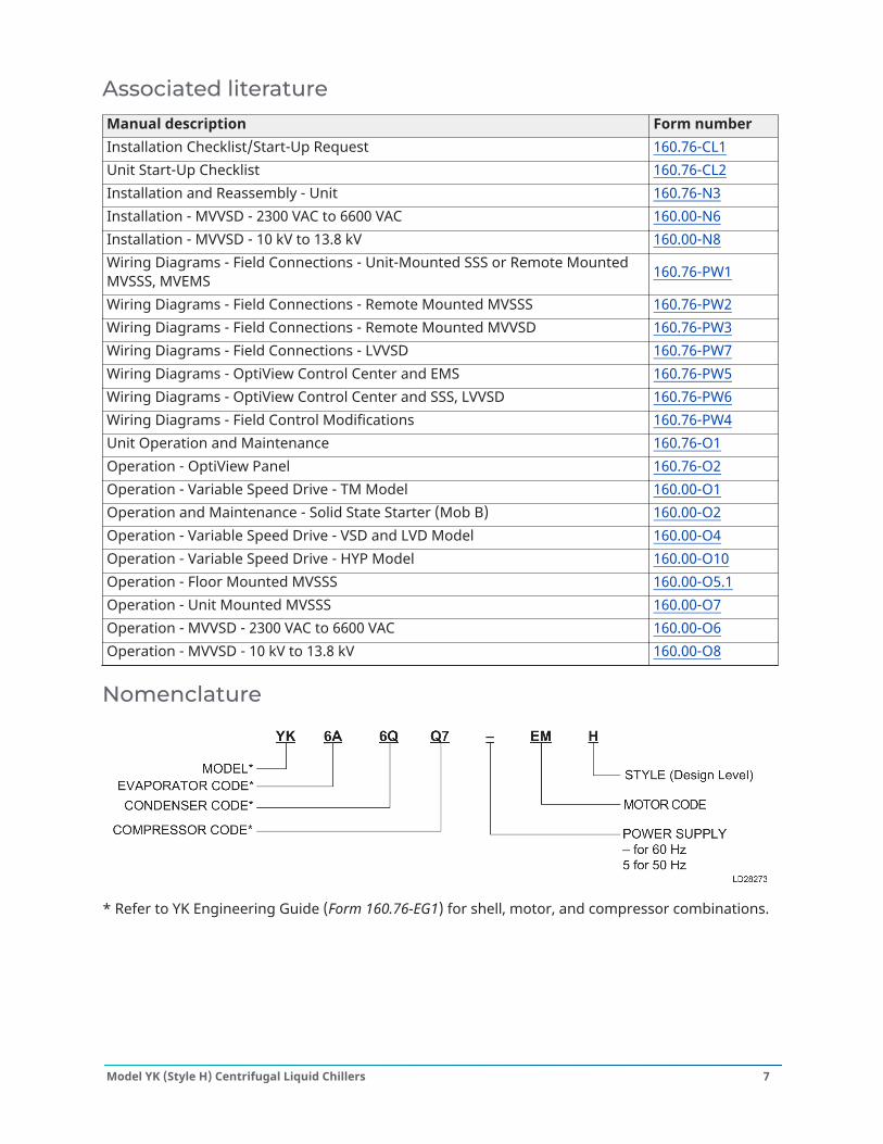
Nomenclature
* Refer to YK Engineering Guide (Form 160.76-EG1) for shell, motor, and compressor combinations.
7Model YK (Style H) Centrifugal Liquid Chillers
IntroductionThis manual describes the installation of a YORK YK Mod H Centrifugal Chiller. This unit can beshipped as a single factory assembled, piped, wired package, requiring a minimum of field laborto make chilled water connections, condenser water connections, refrigerant atmospheric reliefconnections, and electrical power connections. Refrigerant and oil charges are shipped separatelyunless optional condenser isolation valves are ordered.Chillers can also be shipped dismantled when required by rigging conditions, but generally itis more economical to enlarge access openings to accommodate the factory assembled unit.Chillers shipped dismantled MUST be field assembled under the supervision of a Johnson Controlsrepresentative, but otherwise installation is as described in this instruction.
Field assembled units onlyUse Unit - Installation Instructions (Form 160.76-N3) in conjunction with this installation instruction.This instruction is furnished with all units that are assembled in the field.The services of a Johnson Controls representative is furnished to check the installation, supervisethe initial start-up and operation of all chillers installed within the Continental United States.
CAUTION
The Johnson Controls Warranty may be voided if the following restrictions are not adhered to.
• Do not open valves or connections under any circumstances, as such action results in loss ofthe factory nitrogen charge.
• Do not dismantle or open the chiller for any reason except under the supervision of aJohnson Controls representative.
• When the units are shipped dismantled, notify the nearest Johnson Controls office in ampletime for a Johnson Controls representative to supervise rigging the unit to its operatingposition and the assembly of components.
• Do not make final power supply connections to the compressor motor or control center.• Do not charge the compressor with oil.• Do not charge the unit with refrigerant.• Do not attempt to start the system.• Do not run hot water (110°F/43°C max) or steam through the evaporator or condenser at any
time.
Model YK (Style H) Centrifugal Liquid Chillers8
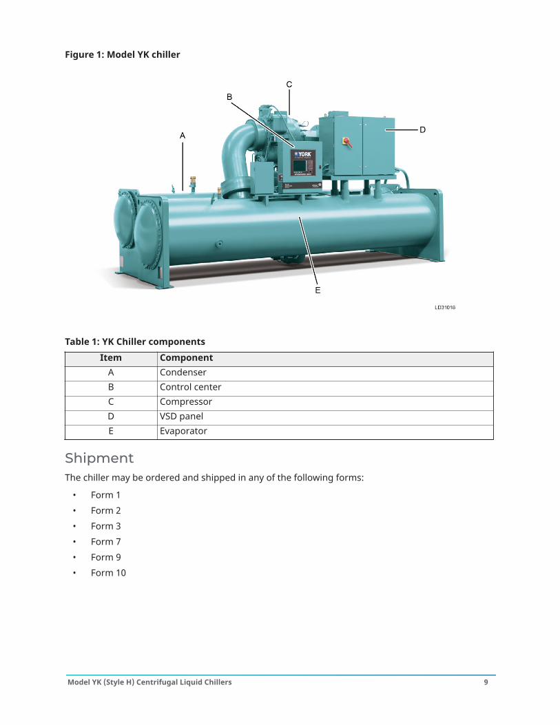
Figure 1: Model YK chiller
Table 1: YK Chiller componentsItem Component
A CondenserB Control centerC CompressorD VSD panelE Evaporator
ShipmentThe chiller may be ordered and shipped in any of the following forms:
• Form 1• Form 2• Form 3• Form 7• Form 9• Form 10
9Model YK (Style H) Centrifugal Liquid Chillers
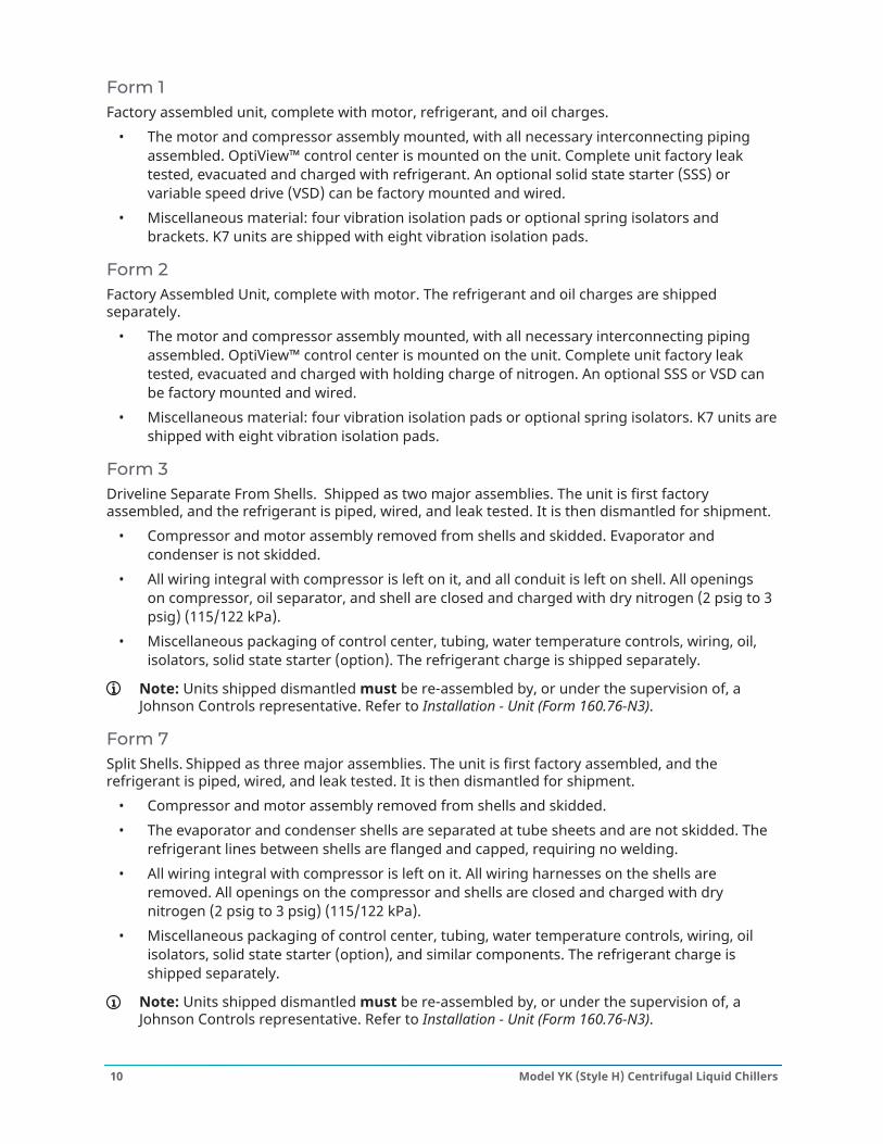
Form 1Factory assembled unit, complete with motor, refrigerant, and oil charges.
• The motor and compressor assembly mounted, with all necessary interconnecting pipingassembled. OptiView™ control center is mounted on the unit. Complete unit factory leaktested, evacuated and charged with refrigerant. An optional solid state starter (SSS) orvariable speed drive (VSD) can be factory mounted and wired.
• Miscellaneous material: four vibration isolation pads or optional spring isolators andbrackets. K7 units are shipped with eight vibration isolation pads.
Form 2Factory Assembled Unit, complete with motor. The refrigerant and oil charges are shippedseparately.
• The motor and compressor assembly mounted, with all necessary interconnecting pipingassembled. OptiView™ control center is mounted on the unit. Complete unit factory leaktested, evacuated and charged with holding charge of nitrogen. An optional SSS or VSD canbe factory mounted and wired.
• Miscellaneous material: four vibration isolation pads or optional spring isolators. K7 units areshipped with eight vibration isolation pads.
Form 3Driveline Separate From Shells. Shipped as two major assemblies. The unit is first factoryassembled, and the refrigerant is piped, wired, and leak tested. It is then dismantled for shipment.
• Compressor and motor assembly removed from shells and skidded. Evaporator andcondenser is not skidded.
• All wiring integral with compressor is left on it, and all conduit is left on shell. All openingson compressor, oil separator, and shell are closed and charged with dry nitrogen (2 psig to 3psig) (115/122 kPa).
• Miscellaneous packaging of control center, tubing, water temperature controls, wiring, oil,isolators, solid state starter (option). The refrigerant charge is shipped separately.
Note: Units shipped dismantled must be re-assembled by, or under the supervision of, aJohnson Controls representative. Refer to Installation - Unit (Form 160.76-N3).
Form 7Split Shells. Shipped as three major assemblies. The unit is first factory assembled, and therefrigerant is piped, wired, and leak tested. It is then dismantled for shipment.
• Compressor and motor assembly removed from shells and skidded.• The evaporator and condenser shells are separated at tube sheets and are not skidded. The
refrigerant lines between shells are flanged and capped, requiring no welding.• All wiring integral with compressor is left on it. All wiring harnesses on the shells are
removed. All openings on the compressor and shells are closed and charged with drynitrogen (2 psig to 3 psig) (115/122 kPa).
• Miscellaneous packaging of control center, tubing, water temperature controls, wiring, oilisolators, solid state starter (option), and similar components. The refrigerant charge isshipped separately.
Note: Units shipped dismantled must be re-assembled by, or under the supervision of, aJohnson Controls representative. Refer to Installation - Unit (Form 160.76-N3).
Model YK (Style H) Centrifugal Liquid Chillers10
When more than one chiller is involved, the major parts of each unit are marked to prevent mixingof assemblies. Piping and wiring drawings are furnished by Johnson Controls.
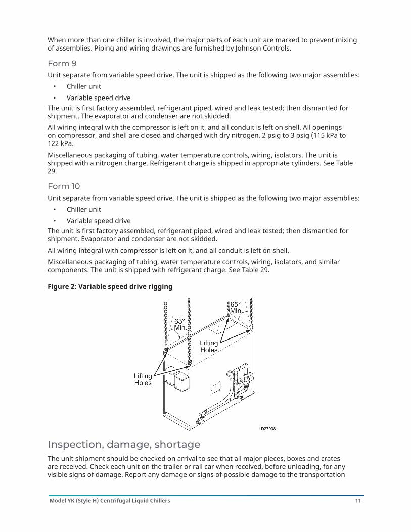
Form 9Unit separate from variable speed drive. The unit is shipped as the following two major assemblies:
• Chiller unit• Variable speed drive
The unit is first factory assembled, refrigerant piped, wired and leak tested; then dismantled forshipment. The evaporator and condenser are not skidded.All wiring integral with the compressor is left on it, and all conduit is left on shell. All openingson compressor, and shell are closed and charged with dry nitrogen, 2 psig to 3 psig (115 kPa to122 kPa.Miscellaneous packaging of tubing, water temperature controls, wiring, isolators. The unit isshipped with a nitrogen charge. Refrigerant charge is shipped in appropriate cylinders. See Table29.
Form 10Unit separate from variable speed drive. The unit is shipped as the following two major assemblies:
• Chiller unit• Variable speed drive
The unit is first factory assembled, refrigerant piped, wired and leak tested; then dismantled forshipment. Evaporator and condenser are not skidded.All wiring integral with compressor is left on it, and all conduit is left on shell.Miscellaneous packaging of tubing, water temperature controls, wiring, isolators, and similarcomponents. The unit is shipped with refrigerant charge. See Table 29.
Figure 2: Variable speed drive rigging
Inspection, damage, shortageThe unit shipment should be checked on arrival to see that all major pieces, boxes and cratesare received. Check each unit on the trailer or rail car when received, before unloading, for anyvisible signs of damage. Report any damage or signs of possible damage to the transportation
11Model YK (Style H) Centrifugal Liquid Chillers
company immediately for their inspection. Johnson Controls is not be responsible for any damagein shipment, at job site, or loss of parts. Refer to Shipping Damage Claims, Form 50.15-NM.When received at the job site, open all containers and check contents against the packing list. Anymaterial shortage must be reported to Johnson Controls immediately. Refer to Shipping DamageClaims, Form 50.15-NM.
Chiller data plateA unit data plate is mounted on the control center assembly of each unit, giving the followinginformation:
• Unit model number• Design working pressure• Water passes• Refrigerant charge• Serial numbers• Motor power characteristics and connection diagrams
Additional information may be found on the motor data plate. Include this information whencontacting the factory on any problem relating to the motor.
Long-term storageAbout this task: To protect the waterbox of pressure vessels from rusting, the tube side (water side) is purged andcharged with nitrogen to a positive pressure of 5 psig to 7 psig.
Do not break the seal or remove closures until ready for setup. Use the following procedure torelieve pressure. See Figure 3.
WARNING
Failure to follow the following procedures will cause severe personal injury or death to operatorsthemselves or people on-site. It is the obligation and responsibility of operators to identify andrecognize the inherent hazards of material under pressure and to protect themselves.
1. Check that the working space is open and has good ventilation. If ventilation is not good,connect a hose or pipe to the valve (Item 5) and route it to outside.
2. Slowly open the valve (Item 5) until fully opened.3. Monitor the pressure gauge (Item 2). The pressure declines gradually.4. When the pointer of the pressure gauge stops moving and no nitrogen is released from the
valve (Item 5), no positive pressure exists in the waterbox.5. When there is no positive pressure in the waterbox, it is safe to remove the flange cover (Item
6) or sealing cap (Item 9).6. Close the valve (Item 5) and remove the warning tag (Item 1).
Model YK (Style H) Centrifugal Liquid Chillers12
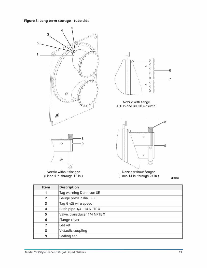
Figure 3: Long term storage - tube side
Item Description1 Tag warning Dennison 8E2 Gauge press 2 dia. 0-303 Tag GlvSt wire speed4 Bush pipe 3/4 - 14 NPTE X5 Valve, transducer 1/4 NPTE X6 Flange cover7 Gasket8 Victaulic coupling9 Sealing cap
13Model YK (Style H) Centrifugal Liquid Chillers
Shipment Forms 2,3,7,9All openings on the compressor, shells including evaporator and condenser, and oil reservoir areclosed and charged with nitrogen (2 psig to 3 psig). To remove the closures, sealing caps, or sealingplug under pressure is extremely dangerous, and may cause severe injury or death to the operatoror people on-site.
WARNING
Before trying to remove the closures, caps, or plugs on compressor and shells, relieve the pressure incompressor, shells, or system that are charged with nitrogen by opening the valves on them slowlyuntil fully open.
WARNING
When relieving the pressure from compressor, shells, or system, conduct the nitrogen to outside toprevent the potential risk of asphyxiation..
Shipment Forms 1,10The unit is shipped with refrigerant charge; it is not necessary to relieve the pressure. Do not try toopen any valves to relieve pressure or open closures, cap, or plugs on the compressor, shells, andelsewhere on the system.Reclaim the refrigerant in the system before carrying out any service activities on the refrigerationsystem. Fully relieve system pressure and then repair.
DANGER
The unit is charged with tons of refrigerant; if an uncontrollable leak is found, inform all of the relevantpeople to evacuate from the building to prevent risk of asphyxiation.
Never touch the refrigerant that is leaking, especially the liquid refrigerant; this will cause severefreezing to your hands or body.
Model YK (Style H) Centrifugal Liquid Chillers14
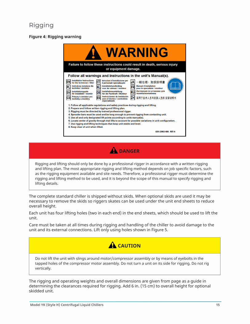
Rigging
Figure 4: Rigging warning
DANGER
Rigging and lifting should only be done by a professional rigger in accordance with a written riggingand lifting plan. The most appropriate rigging and lifting method depends on job specific factors, suchas the rigging equipment available and site needs. Therefore, a professional rigger must determine therigging and lifting method to be used, and it is beyond the scope of this manual to specify rigging andlifting details.
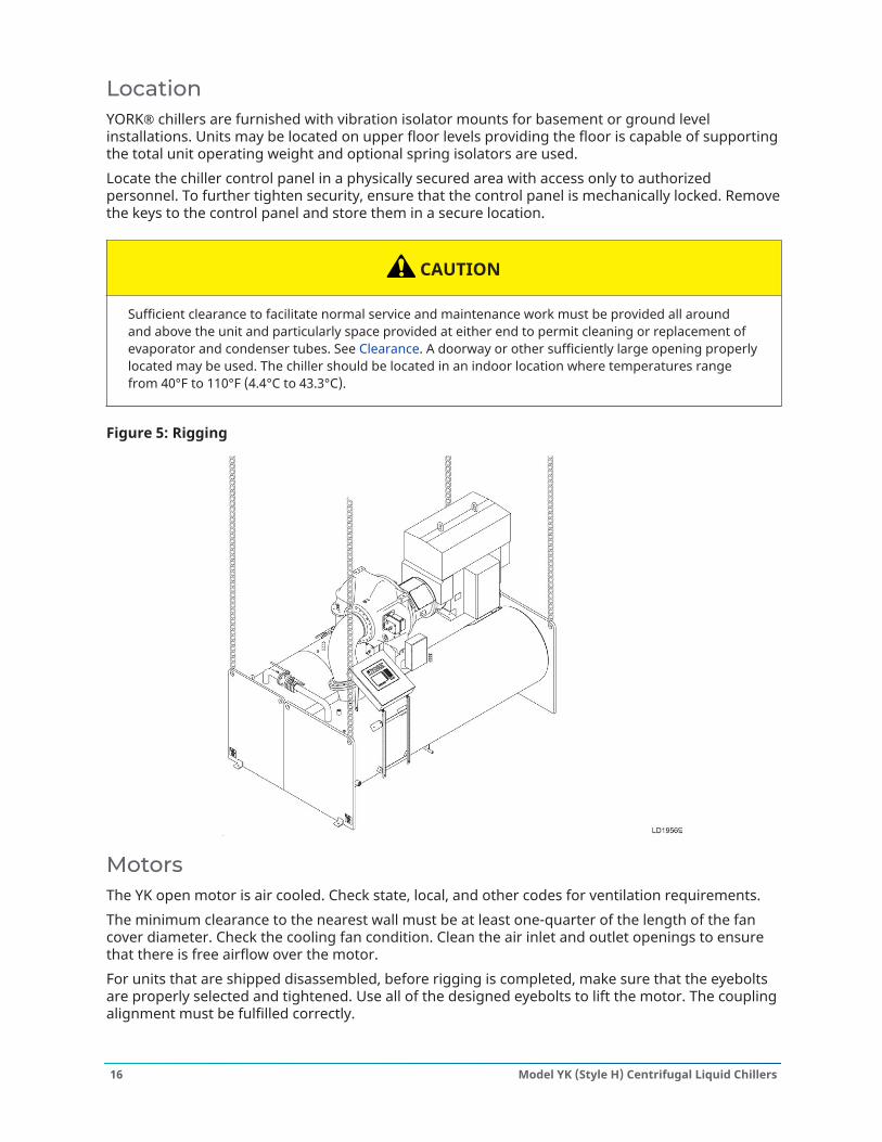
The complete standard chiller is shipped without skids. When optional skids are used it may benecessary to remove the skids so riggers skates can be used under the unit end sheets to reduceoverall height.Each unit has four lifting holes (two in each end) in the end sheets, which should be used to lift theunit.Care must be taken at all times during rigging and handling of the chiller to avoid damage to theunit and its external connections. Lift only using holes shown in Figure 5.
CAUTION
Do not lift the unit with slings around motor/compressor assembly or by means of eyebolts in thetapped holes of the compressor motor assembly. Do not turn a unit on its side for rigging. Do not rigvertically.
The rigging and operating weights and overall dimensions are given from page as a guide indetermining the clearances required for rigging. Add 6 in. (15 cm) to overall height for optionalskidded unit.
15Model YK (Style H) Centrifugal Liquid Chillers
LocationYORK® chillers are furnished with vibration isolator mounts for basement or ground levelinstallations. Units may be located on upper floor levels providing the floor is capable of supportingthe total unit operating weight and optional spring isolators are used.Locate the chiller control panel in a physically secured area with access only to authorizedpersonnel. To further tighten security, ensure that the control panel is mechanically locked. Removethe keys to the control panel and store them in a secure location.
CAUTION
Sufficient clearance to facilitate normal service and maintenance work must be provided all aroundand above the unit and particularly space provided at either end to permit cleaning or replacement ofevaporator and condenser tubes. See Clearance. A doorway or other sufficiently large opening properlylocated may be used. The chiller should be located in an indoor location where temperatures rangefrom 40°F to 110°F (4.4°C to 43.3°C).
Figure 5: Rigging
MotorsThe YK open motor is air cooled. Check state, local, and other codes for ventilation requirements.The minimum clearance to the nearest wall must be at least one-quarter of the length of the fancover diameter. Check the cooling fan condition. Clean the air inlet and outlet openings to ensurethat there is free airflow over the motor.For units that are shipped disassembled, before rigging is completed, make sure that the eyeboltsare properly selected and tightened. Use all of the designed eyebolts to lift the motor. The couplingalignment must be fulfilled correctly.
Model YK (Style H) Centrifugal Liquid Chillers16
FoundationA level floor, mounting pad or foundation must be provided by others, capable of supporting theoperating weight of the unit.
ClearanceClearances must be adhered to as follows:
• Rear and above unit: 2 ft (61 cm)• Front of unit: 3 ft (91 cm)• Tube removal:
- *12 ft (3.7 m) on shell codes: A-A, C-C, E-C, E-E, G-E, either end- *14 ft (4.3 m) on shell codes: B-B, D-D, F-D, F-F, H-F, K-K, M-K, O-O, Q-Q, either end- *16 ft (4.9 m) on shell codes: J-J, L-L, N-L, P-P, R-R, S-S, U-U, either end- *18 ft (5.5 m) on shell codes: T-T, V-V, V-W, W-W, X-W, X-Y, either end- *22 ft (6.7 m) on shell codes: Y-Z, either end
17Model YK (Style H) Centrifugal Liquid Chillers
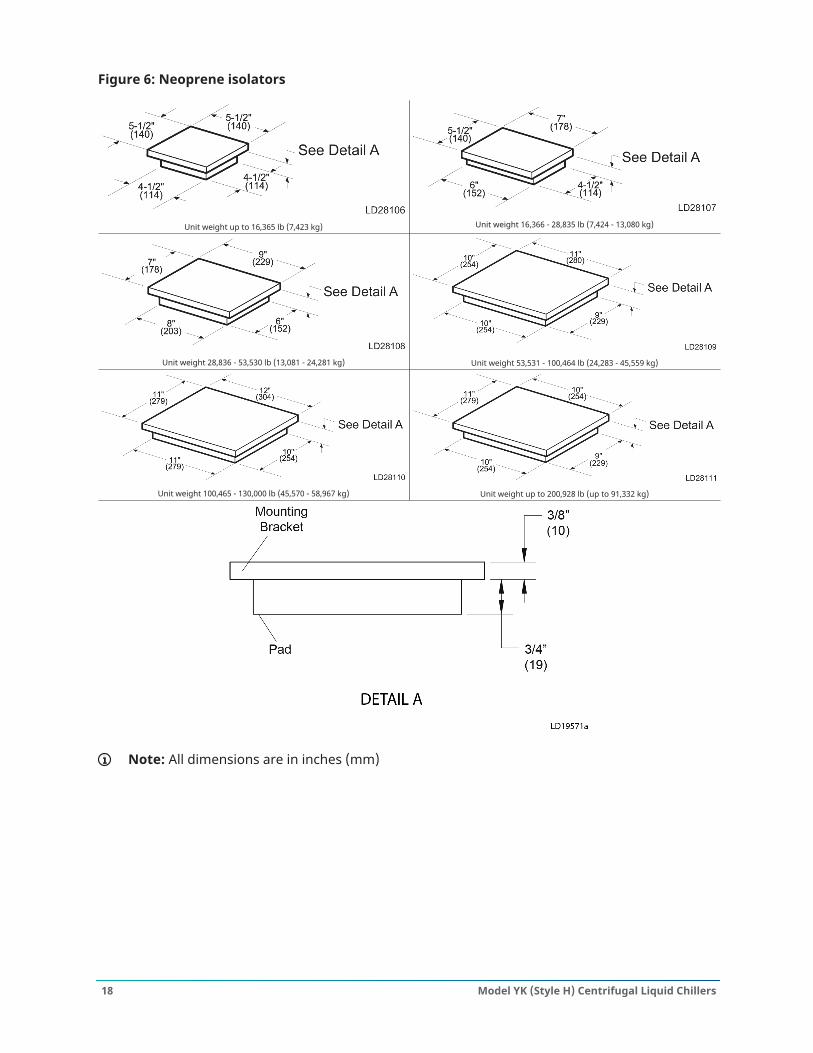
Figure 6: Neoprene isolators
Unit weight up to 16,365 lb (7,423 kg) Unit weight 16,366 - 28,835 lb (7,424 - 13,080 kg)
Unit weight 28,836 - 53,530 lb (13,081 - 24,281 kg) Unit weight 53,531 - 100,464 lb (24,283 - 45,559 kg)
Unit weight 100,465 - 130,000 lb (45,570 - 58,967 kg) Unit weight up to 200,928 lb (up to 91,332 kg)
Note: All dimensions are in inches (mm)
Model YK (Style H) Centrifugal Liquid Chillers18
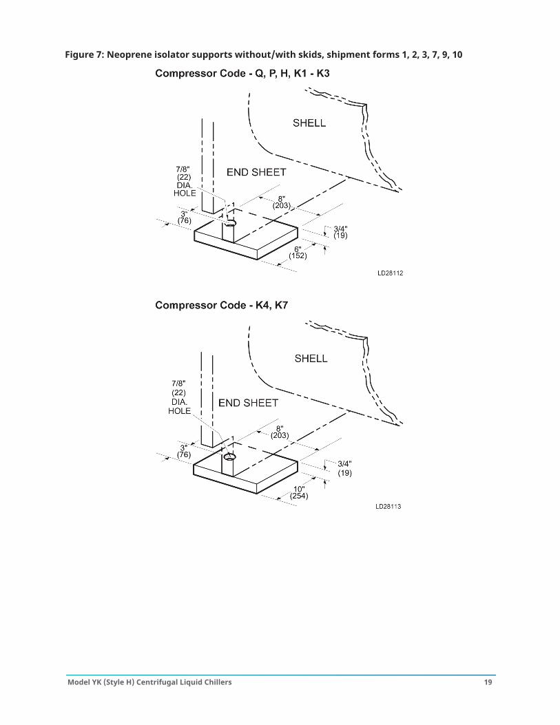
Figure 7: Neoprene isolator supports without/with skids, shipment forms 1, 2, 3, 7, 9, 10
19Model YK (Style H) Centrifugal Liquid Chillers
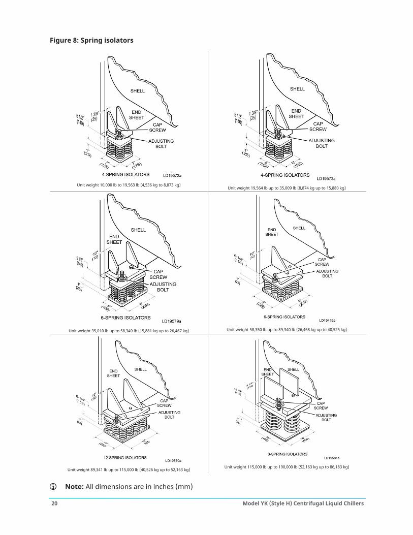
Figure 8: Spring isolators
Unit weight 10,000 lb to 19,563 lb (4,536 kg to 8,873 kg)Unit weight 19,564 lb up to 35,009 lb (8,874 kg up to 15,880 kg)
Unit weight 35,010 lb up to 58,349 lb (15,881 kg up to 26,467 kg) Unit weight 58,350 lb up to 89,340 lb (26,468 kg up to 40,525 kg)
Unit weight 89,341 lb up to 115,000 lb (40,526 kg up to 52,163 kg) Unit weight 115,000 lb up to 190,000 lb (52,163 kg up to 86,183 kg)
Note: All dimensions are in inches (mm)
Model YK (Style H) Centrifugal Liquid Chillers20
Installation
Rigging unit to final locationRig the unit to its final location on the floor or mounting pad, lift the unit (or shell assembly) bymeans of an overhead lift, and lower the unit to its mounting position. If optional shipping skids areused, remove them before lowering the chiller to its mounting position.
Note: At this point, units shipped dismantled must be assembled under the supervision of aJohnson Controls representative.
If the evaporator is to be field insulated, apply the insulation to the evaporator before the unit isplaced in position while the unit is in the lift position. Be sure unit is properly supported. See Figure5.
Locating and installing isolator padsInstall the isolator pad mounts in the location shown in Clearance (rubber side down).After the isolator pads have been placed into position on the floor, lower the chiller onto the pads.When the unit is in place, remove the rigging equipment and check that the unit is level. The unitshould be level within 1/4 in. (6 mm) from one end to the other end and from front to the rear. Ifthe chiller is not level within the amount specified, lift it and place shims between the isolation padand the chiller tube sheets. Shims are furnished by the installer. Lower unit again and recheck tosee that it is level.
Checking the isolation pad deflectionCheck all isolation pads for the proper deflection while also checking to see if the unit is level.Each pad must be deflected approximately 0.10 in. (2.5 mm) to 0.20 in. (5 mm). If an isolation padis under-deflected, shims must be placed between the unit tube sheet and the top of the pad toequally deflect all pads.
Leveling the unitThe longitudinal alignment of the unit should be checked by placing a level on the top center ofthe evaporator shell under the compressor and motor assembly. Transverse alignment should bechecked by placing a level on top of the shell end sheets.
Installing optional spring isolatorsWhen ordered, spring type isolator assemblies are furnished with the unit. The four assemblies areidentical and can be placed at any of the 4 corners of the unit.While the unit is still suspended by the rigging, bolt the isolators to the unit by inserting the capscrews through the holes in the mounting bracket into the tapped hole in the top of the isolatorleveling bolts. The unit can then be lowered onto the floor.Rotate the adjusting bolts now one turn at a time, in sequence, until the unit end sheets are clear ofthe floor by the dimension shown in Figure 8 and the unit is level. Check that the unit is level, bothlongitudinally and transversely (see Leveling the unit). If the leveling bolts are not long enough tolevel unit due to an uneven or sloping floor or foundation, steel shims (grouted, if necessary) mustbe added beneath the isolator assemblies as necessary.After the unit is leveled, wedge and shim under each corner to solidly support the unit in thisposition while piping connections are being made, pipe hangers adjusted, and connections checkedfor alignment. Fill the unit with water and check for leaks. Perform a final adjustment of the leveling
21Model YK (Style H) Centrifugal Liquid Chillers
bolts until the wedges and shims can be removed. The unit should now be in correct level position,clear of the floor or foundation and without any effect from the weight of the piping.
Piping connectionsMake the piping connections after the unit is leveled (and wedged in place for optional springisolators): chilled water, condenser water and refrigerant relief. The piping must be arrangedwith offsets for flexibility, and adequately supported and braced independently of the unit toavoid strain on the unit and vibration transmission. The hangers must allow for alignment ofpipe. Isolators (by others) in the piping and hangers may be necessary, and may be required byspecifications, in order to effectively use the vibration isolation characteristics of the vibrationisolation mounts of the unit.Check for piping alignment: Upon completion of piping, open a connection in each line as closeto the unit as possible. Remove the flange bolts or coupling and check for piping alignment. Ifany of the bolts are bound in their holes, or if the connection springs are out of alignment, themisalignment must be corrected by supporting the piping correctly or by applying heat to annealthe pipe.
Note: If the piping is annealed to relieve stress, the inside of the pipe must be cleaned of scalebefore it is finally bolted in place.
Evaporator and condenser water pipingThe evaporator and condenser liquid heads of the chiller have nozzles which are grooved, suitablefor welding 150 psig DWP flanges or the use of flexible couplings. Factory mounted flanges areoptional.The nozzles and water pass arrangements are furnished in accordance with the job requirements(refer to product drawings) for the job. Standard units are designed for 150 psig DWP on thewater side. If job requirements are for greater than 150 psig DWP, check the unit data plate beforeapplying pressure to evaporator or condenser to determine if the chiller has provisions for therequired DWP.Inlet and outlet connections are identified by labels placed adjacent to each nozzle.The coolant temperature inside any liquid-cooled motor starter supplied by Johnson Controls mustbe maintained above the dewpoint temperature in the equipment room to prevent condensingwater vapor inside the starter cabinet. To ensure this, an additional temperature-controlled throttlevalve is needed in the flow path for the starter heat exchanger to regulate cooling above theequipment room dewpoint, for applications using cooling sources other than evaporative air-exchange methods, such as wells, bodies of water, and chilled water. The temperature controlvalve must be the type to open on increasing drive coolant temperature, fail-closed, and set for atemperature above dewpoint. It can be requested as factory-supplied on a chiller order by specialquotation.
Model YK (Style H) Centrifugal Liquid Chillers22
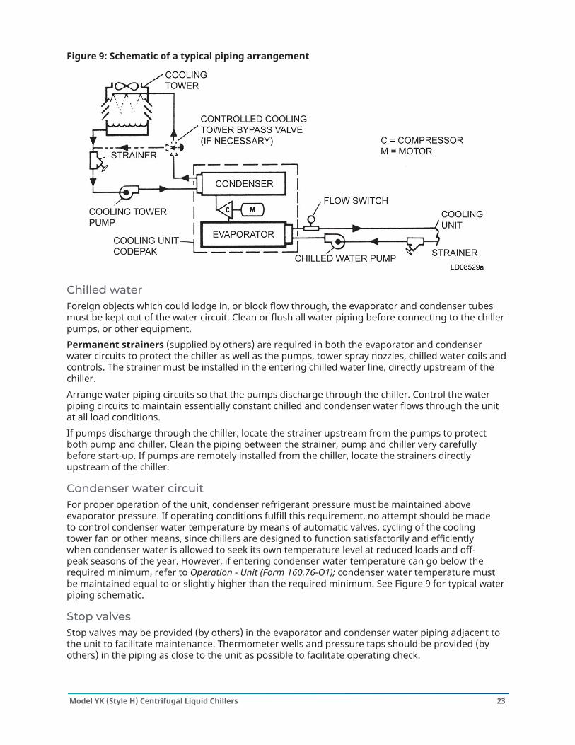
Figure 9: Schematic of a typical piping arrangement
Chilled waterForeign objects which could lodge in, or block flow through, the evaporator and condenser tubesmust be kept out of the water circuit. Clean or flush all water piping before connecting to the chillerpumps, or other equipment.Permanent strainers (supplied by others) are required in both the evaporator and condenserwater circuits to protect the chiller as well as the pumps, tower spray nozzles, chilled water coils andcontrols. The strainer must be installed in the entering chilled water line, directly upstream of thechiller.Arrange water piping circuits so that the pumps discharge through the chiller. Control the waterpiping circuits to maintain essentially constant chilled and condenser water flows through the unitat all load conditions.If pumps discharge through the chiller, locate the strainer upstream from the pumps to protectboth pump and chiller. Clean the piping between the strainer, pump and chiller very carefullybefore start-up. If pumps are remotely installed from the chiller, locate the strainers directlyupstream of the chiller.
Condenser water circuitFor proper operation of the unit, condenser refrigerant pressure must be maintained aboveevaporator pressure. If operating conditions fulfill this requirement, no attempt should be madeto control condenser water temperature by means of automatic valves, cycling of the coolingtower fan or other means, since chillers are designed to function satisfactorily and efficientlywhen condenser water is allowed to seek its own temperature level at reduced loads and off-peak seasons of the year. However, if entering condenser water temperature can go below therequired minimum, refer to Operation - Unit (Form 160.76-O1); condenser water temperature mustbe maintained equal to or slightly higher than the required minimum. See Figure 9 for typical waterpiping schematic.
Stop valvesStop valves may be provided (by others) in the evaporator and condenser water piping adjacent tothe unit to facilitate maintenance. Thermometer wells and pressure taps should be provided (byothers) in the piping as close to the unit as possible to facilitate operating check.
23Model YK (Style H) Centrifugal Liquid Chillers
Flow switchesThermal type water flow switches are factory mounted in the chilled and condensed water nozzlesand are factory wired to the OptiView control panel. These solid-state flow sensors have a smallinternal heating element and use the cooling effect of the flowing fluid to sense when an adequateflow rate has been established.Paddle flow switches are also offered according to the design working pressure (DWP) of thewaterbox. If the DWP is 150 psig, select P/N 024-26116-000 for a flow switch with low energy goldflash contacts. For 300 psig, choose the flow switch with P/N 024-12144-000.Additionally, a differential pressure switch is available with 300 psi of maximum working pressure.The operating range of the differential pressure switch is up to 40 psi, with a deadband of 0.5 psito 0.8 psi. It has 1/4 NPTE pressure connections and 1/2 in. NPT conduit entry. The P/N for thedifferential pressure switch is 025-30919-000.
Waterbox drain and vent valvesDrain and vent valves (by others) must be installed in the connections provided in the evaporatorand condenser liquid heads. These connections can be piped to drain.
Checking piping circuits and venting airAfter the water piping is completed, but before any waterbox insulation is applied, tighten andtorque the nuts on the liquid head flanges to maintain between 30 and 60 ft. lbs. (41 and 81N·m). Gasket shrinkage and handling during transit can cause nuts to loosen. Applying waterpressure before tightening can damage the gaskets, requiring their replacement. Fill the chilledand condenser water circuits, operate the pumps manually and carefully check the evaporator andcondenser water heads and piping for leaks. Repair leaks as necessary.Before initial operation of the unit, vent both water circuits thoroughly of all air at the high points.
Unit pipingCompressor lubricant piping and system external piping are factory installed on all units shippedassembled. On units shipped dismantled, the following piping must be completed under thesupervision of the Johnson Controls representative: the lubricant piping to oil sump and oil coolerand system oil return connections using material furnished. Refer to Installation - Unit (Form 160.76-N3).
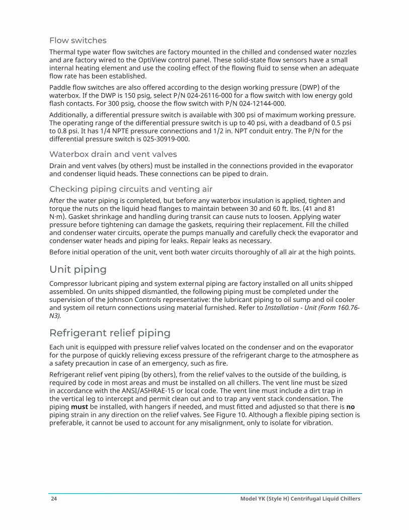
Refrigerant relief pipingEach unit is equipped with pressure relief valves located on the condenser and on the evaporatorfor the purpose of quickly relieving excess pressure of the refrigerant charge to the atmosphere asa safety precaution in case of an emergency, such as fire.Refrigerant relief vent piping (by others), from the relief valves to the outside of the building, isrequired by code in most areas and must be installed on all chillers. The vent line must be sizedin accordance with the ANSI/ASHRAE-15 or local code. The vent line must include a dirt trap inthe vertical leg to intercept and permit clean out and to trap any vent stack condensation. Thepiping must be installed, with hangers if needed, and must fitted and adjusted so that there is nopiping strain in any direction on the relief valves. See Figure 10. Although a flexible piping section ispreferable, it cannot be used to account for any misalignment, only to isolate for vibration.
Model YK (Style H) Centrifugal Liquid Chillers24
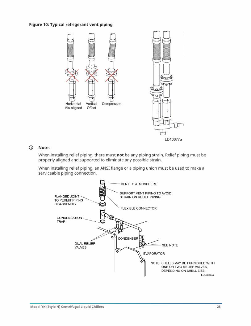
Figure 10: Typical refrigerant vent piping
Note:
When installing relief piping, there must not be any piping strain. Relief piping must beproperly aligned and supported to eliminate any possible strain.
When installing relief piping, an ANSI flange or a piping union must be used to make aserviceable piping connection.
25Model YK (Style H) Centrifugal Liquid Chillers
Control panel positioningAbout this task: On large YK chillers equipped with H9 and K1-K7 compressors, the control panel height can beadjusted. On chillers that are equipped with P and Q compressors, the control panel height is notadjustable. The OptiView™ control center is placed in a position above the evaporator for shipping.
To move the control center into position for operation, proceed as follows:
1. Remove the hardware between the support arms and the evaporator, while supporting thecontrol center. .
2. Swing the control center into a vertical position.3. Slide the control center down the guide rails to the proper position. Tighten securely.4. Discard unused hardware.
Figure 11: Control panel positioning
Control wiringYou must complete the control wiring on units shipped disassembled. After installation of thecontrol center, use the wiring harnesses furnished to complete the control wiring between unitcomponents and the control center, solid state starter, or variable speed drive, when used. Refer toInstallation - Unit (Form 160.76-N3).Field wiring connections for commonly encountered control modifications (by others) if required,are shown on Wiring Diagram – Unit (Style H) Field Control Modifications (Form 160.76-PW4).
Note: No deviations in unit wiring from that shown on drawings furnished can be madewithout prior approval of the Johnson Controls representative.
Model YK (Style H) Centrifugal Liquid Chillers26
Power wiringChiller with electromechanical starterA 115 V – single phase – 60 Hz or 50 Hz power supply of 20 A must be furnished to the controlcenter, from the control transformer (2 KVA required) included with the compressor motor starter.Do not make final power connections to control center until approved by YORK representative.
Oil pump – three-phase starterSeparate wiring or a fused disconnect switch must be supplied by the installer.
Note: Remote electromechanical starters for the chiller must be furnished in accordance withYORK Starter Specifications Product Drawing, Form 160.76-PW5 to provide the features necessaryfor the starter to function correctly with the YORK control system.
Each chiller unit is furnished for a specific electrical power supply as stamped on the unit data plate,which also details the motor connection diagrams.
Note: To insure correct motor rotation, the starter power input and starter to motorconnections must be checked with a phase sequence indicator in the presence of the JohnsonControls representative.
CAUTION
DO NOT cut wires to final length or make final connections to motor terminals or starter power inputterminals until approved by the Johnson Controls representative.
YK motors (electromechanical starter)Motor leads are furnished with a crimp type connection having a clearance hole for a 3/8 in. bolt,motor terminal lugs are not furnished. Refer to Wiring Labels in motor terminal box for hook-up tosuit motor voltage and amperage for power wiring connections.
Chiller with solid state starter or variable speed driveA chiller equipped with a factory mounted solid state starter or variable speed drive does notrequire wiring to the compressor motor. The motor power wiring is factory connected to the solidstate starter or variable speed drive. Refer to the Field Wiring Diagram. All wiring to the controlpanel and the oil pump starter is completed by the factory. A control transformer is furnished withthe solid state starter or variable speed drive.
CAUTION
Copper Conductors – Only connect copper conductors to compressor motors and starters. Aluminumconductors have proven to be unsatisfactory when connected to copper lugs. Aluminum oxide and thedifference in thermal conductivity between copper and aluminum mean the required tight connectioncannot be guaranteed over a long period of time.
27Model YK (Style H) Centrifugal Liquid Chillers
Insulation
CAUTION
DO NOT field insulate until the unit has been leak tested under the supervision of the Johnson Controlsrepresentative.
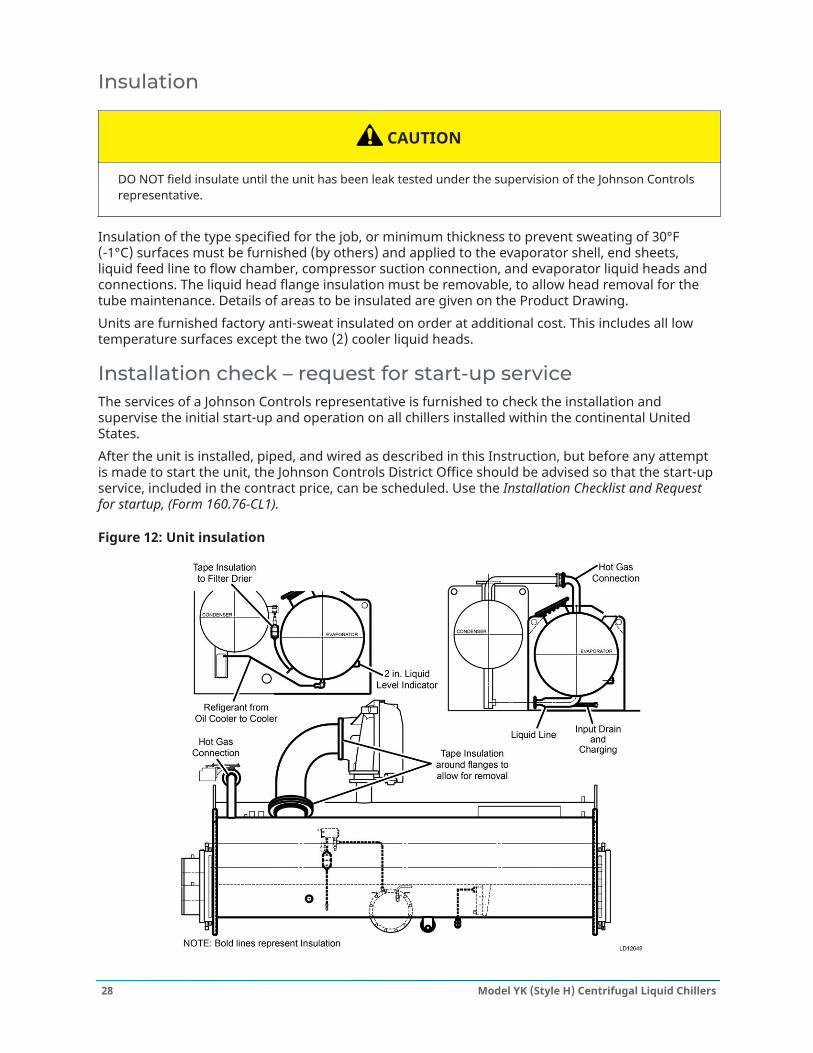
Insulation of the type specified for the job, or minimum thickness to prevent sweating of 30°F(-1°C) surfaces must be furnished (by others) and applied to the evaporator shell, end sheets,liquid feed line to flow chamber, compressor suction connection, and evaporator liquid heads andconnections. The liquid head flange insulation must be removable, to allow head removal for thetube maintenance. Details of areas to be insulated are given on the Product Drawing.Units are furnished factory anti-sweat insulated on order at additional cost. This includes all lowtemperature surfaces except the two (2) cooler liquid heads.
Installation check – request for start-up serviceThe services of a Johnson Controls representative is furnished to check the installation andsupervise the initial start-up and operation on all chillers installed within the continental UnitedStates.After the unit is installed, piped, and wired as described in this Instruction, but before any attemptis made to start the unit, the Johnson Controls District Office should be advised so that the start-upservice, included in the contract price, can be scheduled. Use the Installation Checklist and Requestfor startup, (Form 160.76-CL1).
Figure 12: Unit insulation
Model YK (Style H) Centrifugal Liquid Chillers28
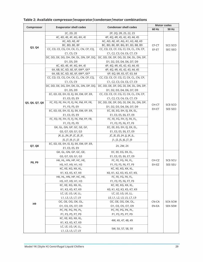
Table 2: Available compressor/evaporator/condenser/motor combinationsMotor codes
Compressor Evaporator shell codes Condenser shell codes60 Hz 50 Hz
2C, 2D, 2E 2P, 2Q, 2R, 2S, 22, 234C, 4D, 4E, 4F, 4G, 4H, 4I 4P, 4Q, 4R, 4S, 42, 43, 44, 45
AC, AD, AE, AF AC, AD, AE, AF, AG, A1, A3, A8, A9BC, BD, BE, BF BC, BD, BE, BF, BG, B1, B3, B8, B9
CC, CD, CE, CG, CH, CK, CL, CN, CP, CQ,C1, C5, C9
CC, CD, CE, CF, CG, CI, CK, CL, CN, CP,C1, C2, C3, C4, C6, C7, C9
Q3, Q4
DC, DD, DE, DG, DH, DK, DL, DN, DP, DQ,D1, D5, D9
DC, DD, DE, DF, DG, DI, DK, DL, DN, DP,D1, D2, D3, D4, D6, D7, D9
CF-CTEF-ET
5CC-5CO5EC-5EO
4C, 4D, 4E, 4F, 4G, 4H, 4I 4P, 4Q, 4R, 4S, 42, 43, 44, 456A, 6B, 6C, 6D, 6E, 6F, 6W*, 6X* 4P, 4Q, 4R, 4S, 42, 43, 44, 456A, 6B, 6C, 6D, 6E, 6F, 6W*, 6X* 6P, 6Q, 6R, 6S, 6T, 63, 64
CC, CD, CE, CG, CH, CK, CL, CN, CP, CQ,C1, C5, C9
CC, CD, CE, CF, CG, CI, CK, CL, CN, CP,C1, C2, C3, C4, C6, C7, C9
DC, DD, DE, DG, DH, DK, DL, DN, DP, DQ,D1, D5, D9
DC, DD, DE, DF, DG, DI, DK, DL, DN, DP,D1, D2, D3, D4, D6, D7, D9
EC, ED, EE, EH, EI, EJ, EK, EM, EP, ER,E1, E3, E5, E9
CC, CD, CE, CF, CG, CI, CK, CL, CN, CP,C1, C2, C3, C4, C6, C7, C9
FC, FD, FE, FH, FI, FJ, FK, FM, FP, FR,F1, F3, F5, E9
DC, DD, DE, DF, DG, DI, DK, DL, DN, DP,D1, D2, D3, D4, D6, D7, D9
EC, ED, EE, EH, EI, EJ, EK, EM, EP, ER,E1, E3, E5, E9
EC, EE, EG, EH, EJ, EK, EL,E1, E3, E5, E6, E7, E9
FC, FD, FE, FH, FI, FJ, FK, FM, FP, FR,F1, F3, F5, F9
FC, FE, FG, FH, FJ, FK, FL,F1, F3, F5, F6, F7, F9
GK, GL, GN, GP, GC, GE, GF,G5, G7, G9, G1, G3
EC, EE, EG, EH, EJ, EK, EL,E1, E3, E5, E6, E7, E9
Q5, Q6, Q7, Q8
JK, JL, JN, JP, JC, JE, JF,J5, J7, J9, J1, J3
JC, JE, JG, JH, JJ, JK, JL,J1, J3, J5, J6, J7, J9
Q7, Q8EC, ED, EE, EH, EI, EJ, EK, EM, EP, ER,
E1, E3, E5, E92V, 2W, 2X
CH-CTEH-ET
5CE-5CO5EE-5EO
GK, GL, GN, GP, GC, GE,G5, G7, G9, G1, G3
EC, EE, EG, EK, EL,E1, E3, E5, E6, E7, E9
HK, HL, HN, HP, HC, HE,H5, H7, H9, H1, H3
FC, FE, FG, FK, FL,F1, F3, F5, F6, F7, F9
P8, P9
KC, KE, KG, KK, KL,K1, K3, K5, K7, K9
KC, KE, KG, KK, KL,K0, K1, K2, K3, K5, K7, K9,
CH-CZEH-EZ
5CE-5CU5EE-5EU
HK, HL, HN, HP, HC, HE,H5, H7, H9, H1, H3
FC, FE, FG, FK, FL,F1, F3, F5, F6, F7, F9
KC, KE, KG, KK, KL,K1, K3, K5, K7, K9
KC, KE, KG, KK, KL,K0, K1, K2, K3, K5, K7, K9
LC, LE, LG, LK, LL,L1, L3, L5, L7, L9
LC, LE, LG, LK, LL,L0, L1, L2, L3, L5, L7, L9
OC, OE, OG, OK, OL,O1, O3, O5, O7, O9
OC, OE, OG, OK, OL,O1, O3, O5, O7, O9
PC, PE, PG, PK, PL,P1, P3, P5, P7, P9
PC, PE, PG, PK, PL,P1, P3, P5, P7, P9
KC, KE, KG, KK, KL,K1, K3, K5, K7, K9
4W, 4X, 47, 48, 49
H9
LC, LE, LG, LK, LL,L1, L3, L5, L7, L9
5W, 5X, 57, 58, 59
CN-CAEN-EA
5CK-5CW5EK-5EW
29Model YK (Style H) Centrifugal Liquid Chillers
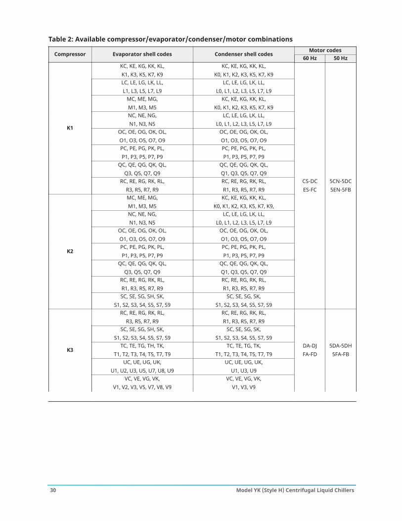
Table 2: Available compressor/evaporator/condenser/motor combinationsMotor codes
Compressor Evaporator shell codes Condenser shell codes60 Hz 50 Hz
KC, KE, KG, KK, KL,K1, K3, K5, K7, K9
KC, KE, KG, KK, KL,K0, K1, K2, K3, K5, K7, K9
LC, LE, LG, LK, LL,L1, L3, L5, L7, L9
LC, LE, LG, LK, LL,L0, L1, L2, L3, L5, L7, L9
MC, ME, MG,M1, M3, M5
KC, KE, KG, KK, KL,K0, K1, K2, K3, K5, K7, K9
NC, NE, NG,N1, N3, N5
LC, LE, LG, LK, LL,L0, L1, L2, L3, L5, L7, L9
OC, OE, OG, OK, OL,O1, O3, O5, O7, O9
OC, OE, OG, OK, OL,O1, O3, O5, O7, O9
PC, PE, PG, PK, PL,P1, P3, P5, P7, P9
PC, PE, PG, PK, PL,P1, P3, P5, P7, P9
QC, QE, QG, QK, QL,Q3, Q5, Q7, Q9
QC, QE, QG, QK, QL,Q1, Q3, Q5, Q7, Q9
K1
RC, RE, RG, RK, RL,R3, R5, R7, R9
RC, RE, RG, RK, RL,R1, R3, R5, R7, R9
MC, ME, MG,M1, M3, M5
KC, KE, KG, KK, KL,K0, K1, K2, K3, K5, K7, K9,
NC, NE, NG,N1, N3, N5
LC, LE, LG, LK, LL,L0, L1, L2, L3, L5, L7, L9
OC, OE, OG, OK, OL,O1, O3, O5, O7, O9
OC, OE, OG, OK, OL,O1, O3, O5, O7, O9
PC, PE, PG, PK, PL,P1, P3, P5, P7, P9
PC, PE, PG, PK, PL,P1, P3, P5, P7, P9
QC, QE, QG, QK, QL,Q3, Q5, Q7, Q9
QC, QE, QG, QK, QL,Q1, Q3, Q5, Q7, Q9
RC, RE, RG, RK, RL,R1, R3, R5, R7, R9
RC, RE, RG, RK, RL,R1, R3, R5, R7, R9
K2
SC, SE, SG, SH, SK,S1, S2, S3, S4, S5, S7, S9
SC, SE, SG, SK,S1, S2, S3, S4, S5, S7, S9
CS-DCES-FC
5CN-5DC5EN-5FB
RC, RE, RG, RK, RL,R3, R5, R7, R9
RC, RE, RG, RK, RL,R1, R3, R5, R7, R9
SC, SE, SG, SH, SK,S1, S2, S3, S4, S5, S7, S9
SC, SE, SG, SK,S1, S2, S3, S4, S5, S7, S9
TC, TE, TG, TH, TK,T1, T2, T3, T4, T5, T7, T9
TC, TE, TG, TK,T1, T2, T3, T4, T5, T7, T9
UC, UE, UG, UK,U1, U2, U3, U5, U7, U8, U9
UC, UE, UG, UK,U1, U3, U9
K3
VC, VE, VG, VK,V1, V2, V3, V5, V7, V8, V9
VC, VE, VG, VK,V1, V3, V9
DA-DJFA-FD
5DA-5DH5FA-FB
Model YK (Style H) Centrifugal Liquid Chillers30
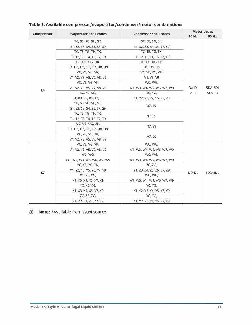
Table 2: Available compressor/evaporator/condenser/motor combinationsMotor codes
Compressor Evaporator shell codes Condenser shell codes60 Hz 50 Hz
SC, SE, SG, SH, SK,S1, S2, S3, S4, S5, S7, S9
SC, SE, SG, SK,S1, S2, S3, S4, S5, S7, S9
TC, TE, TG, TH, TK,T1, T2, T3, T4, T5, T7, T9
TC, TE, TG, TK,T1, T2, T3, T4, T5, T7, T9
UC, UE, UG, UK,U1, U2, U3, U5, U7, U8, U9
UC, UE, UG, UK,U1, U3, U9
VC, VE, VG, VK,V1, V2, V3, V5, V7, V8, V9
VC, VE, VG, VK,V1, V3, V9
VC, VE, VG, VK,V1, V2, V3, V5, V7, V8, V9
WC, WG,W1, W3, W4, W5, W6, W7, W9
XC, XE, XG,X1, X3, X5, X6, X7, X9
YC, YG,Y1, Y2, Y3, Y4, Y5, Y7, Y9
SC, SE, SG, SH, SK,S1, S2, S3, S4, S5, S7, S9
87, 89
TC, TE, TG, TH, TK,T1, T2, T3, T4, T5, T7, T9
97, 99
UC, UE, UG, UK,U1, U2, U3, U5, U7, U8, U9
87, 89
K4
VC, VE, VG, VK,V1, V2, V3, V5, V7, V8, V9
97, 99
DA-DJFA-FD
5DA-5DJ5FA-FB
VC, VE, VG, VK,V1, V2, V3, V5, V7, V8, V9
WC, WG,W1, W3, W4, W5, W6, W7, W9
WC, WG,W1, W2, W3, W5, W6, W7, W9
WC, WG,W1, W3, W4, W5, W6, W7, W9
YC, YE, YG, YK,Y1, Y2, Y3, Y5, Y6, Y7, Y9
ZC, ZG,Z1, Z3, Z4, Z5, Z6, Z7, Z9
XC, XE, XG,X1, X3, X5, X6, X7, X9
WC, WG,W1, W3, W4, W5, W6, W7, W9
XC, XE, XG,X1, X3, X5, X6, X7, X9
YC, YG,Y1, Y2, Y3, Y4, Y5, Y7, Y9
K7
ZC, ZE, ZG,Z1, Z2, Z3, Z5, Z7, Z9
YC, YG,Y1, Y2, Y3, Y4, Y5, Y7, Y9
DD-DL 5DD-5DL
Note: *Available from Wuxi source.
31Model YK (Style H) Centrifugal Liquid Chillers
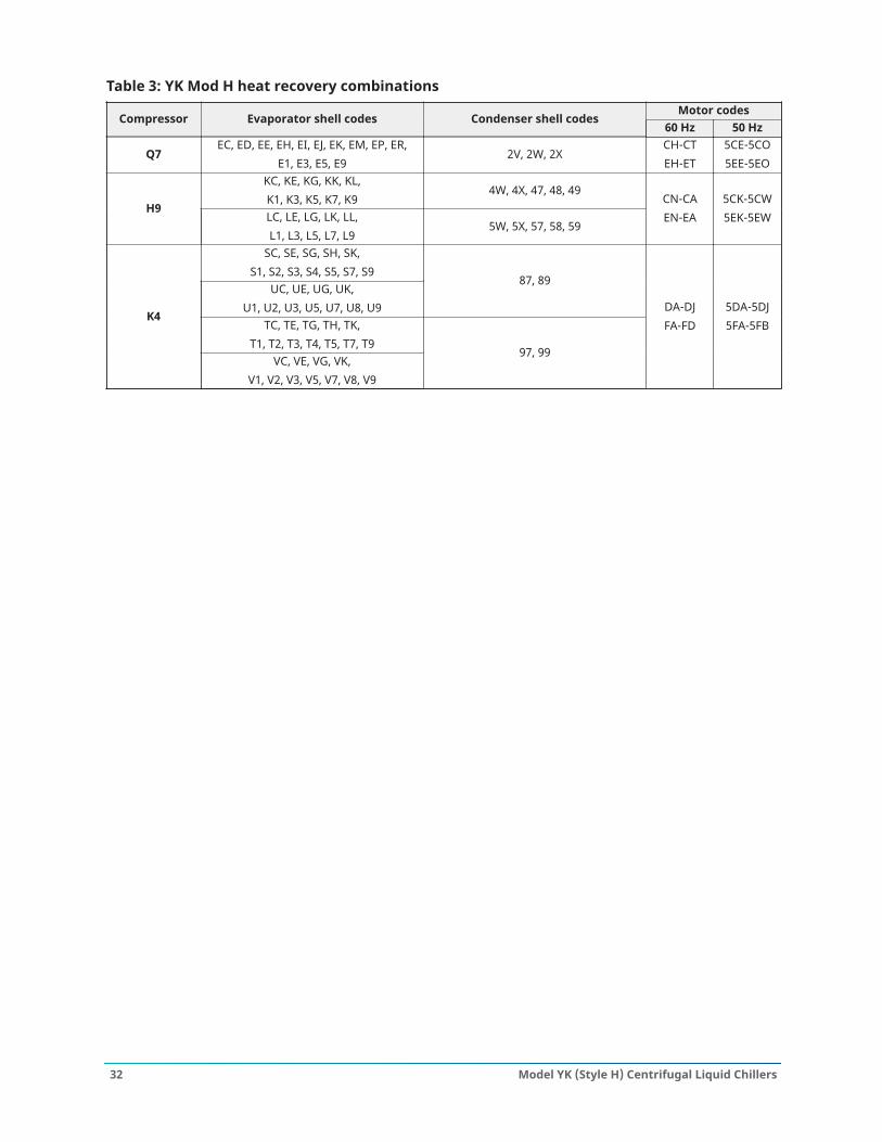
Table 3: YK Mod H heat recovery combinationsMotor codes
Compressor Evaporator shell codes Condenser shell codes60 Hz 50 Hz
Q7EC, ED, EE, EH, EI, EJ, EK, EM, EP, ER,
E1, E3, E5, E92V, 2W, 2X
CH-CTEH-ET
5CE-5CO5EE-5EO
KC, KE, KG, KK, KL,K1, K3, K5, K7, K9
4W, 4X, 47, 48, 49H9
LC, LE, LG, LK, LL,L1, L3, L5, L7, L9
5W, 5X, 57, 58, 59
CN-CAEN-EA
5CK-5CW5EK-5EW
SC, SE, SG, SH, SK,S1, S2, S3, S4, S5, S7, S9
UC, UE, UG, UK,U1, U2, U3, U5, U7, U8, U9
87, 89
TC, TE, TG, TH, TK,T1, T2, T3, T4, T5, T7, T9
K4
VC, VE, VG, VK,V1, V2, V3, V5, V7, V8, V9
97, 99
DA-DJFA-FD
5DA-5DJ5FA-5FB
Model YK (Style H) Centrifugal Liquid Chillers32
Compressor units
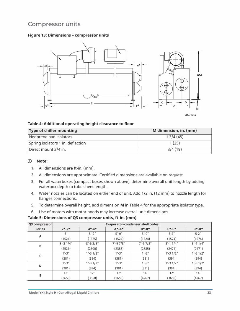
Figure 13: Dimensions – compressor units
Table 4: Additional operating height clearance to floorType of chiller mounting M dimension, in. (mm)Neoprene pad isolators 1 3/4 (45)Spring isolators 1 in. deflection 1 (25)Direct mount 3/4 in. 3/4 (19)
Note:
1. All dimensions are ft-in. (mm).2. All dimensions are approximate. Certified dimensions are available on request.3. For all waterboxes (compact boxes shown above), determine overall unit length by adding
waterbox depth to tube sheet length.4. Water nozzles can be located on either end of unit. Add 1/2 in. (12 mm) to nozzle length for
flanges connections.5. To determine overall height, add dimension M in Table 4 for the appropriate isolator type.6. Use of motors with motor hoods may increase overall unit dimensions.
Table 5: Dimensions of Q3 compressor units, ft-in. (mm)Q3 compressor Evaporator-condenser shell codes
Series 2*-2* 4*-4* A*-A* B*-B* C*-C* D*-D*
A5'
(1524)5'-2"
(1575)5'-0"
(1524)5'-0"
(1524)5-2"
(1574)5-2"
(1574)
B8'-3 1/4"
(2521)8'-6 3/8"
(2600)7'-9 7/8"
(2385)7'-9 7/8"
(2385)8'-1 1/4"
(2471)8'-1 1/4"
(2471)
C1'-3"(381)
1'-3 1/2"(394)
1'-3"(381)
1'-3"(381)
1'-3 1/2"(394)
1'-3 1/2"(394)
D1'-3"(381)
1'-3 1/2"(394)
1'-3"(381)
1'-3"(381)
1'-3 1/2"(394)
1'-3 1/2"(394)
E12'
(3658)12'
(3658)12'
(3658)14'
(4267)12'
(3658)14'
(4267)
33Model YK (Style H) Centrifugal Liquid Chillers
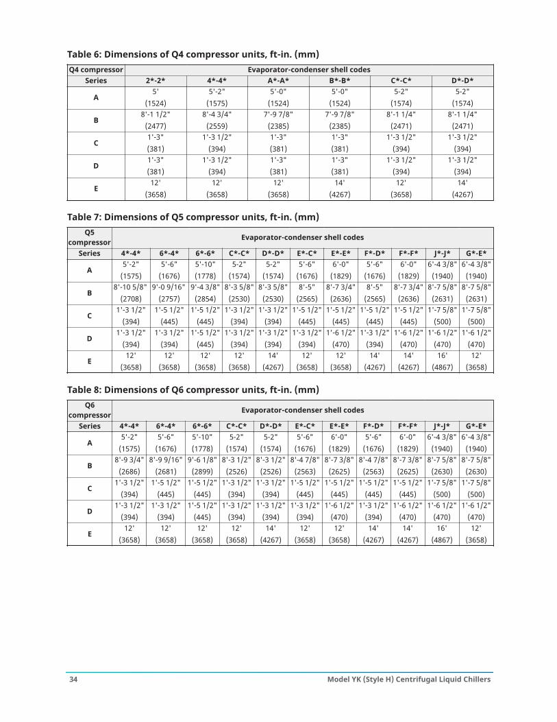
Table 6: Dimensions of Q4 compressor units, ft-in. (mm)Q4 compressor Evaporator-condenser shell codes
Series 2*-2* 4*-4* A*-A* B*-B* C*-C* D*-D*
A5'
(1524)5'-2"
(1575)5'-0"
(1524)5'-0"
(1524)5-2"
(1574)5-2"
(1574)
B8'-1 1/2"
(2477)8'-4 3/4"
(2559)7'-9 7/8"
(2385)7'-9 7/8"
(2385)8'-1 1/4"
(2471)8'-1 1/4"
(2471)
C1'-3"(381)
1'-3 1/2"(394)
1'-3"(381)
1'-3"(381)
1'-3 1/2"(394)
1'-3 1/2"(394)
D1'-3"(381)
1'-3 1/2"(394)
1'-3"(381)
1'-3"(381)
1'-3 1/2"(394)
1'-3 1/2"(394)
E12'
(3658)12'
(3658)12'
(3658)14'
(4267)12'
(3658)14'
(4267)
Table 7: Dimensions of Q5 compressor units, ft-in. (mm)Q5
compressor Evaporator-condenser shell codes
Series 4*-4* 6*-4* 6*-6* C*-C* D*-D* E*-C* E*-E* F*-D* F*-F* J*-J* G*-E*
A5'-2"
(1575)5'-6"
(1676)5'-10"(1778)
5-2"(1574)
5-2"(1574)
5'-6"(1676)
6'-0"(1829)
5'-6"(1676)
6'-0"(1829)
6'-4 3/8"(1940)
6'-4 3/8"(1940)
B8'-10 5/8"
(2708)9'-0 9/16"
(2757)9'-4 3/8"
(2854)8'-3 5/8"
(2530)8'-3 5/8"
(2530)8'-5"
(2565)8'-7 3/4"
(2636)8'-5"
(2565)8'-7 3/4"
(2636)8'-7 5/8"
(2631)8'-7 5/8"
(2631)
C1'-3 1/2"
(394)1'-5 1/2"
(445)1'-5 1/2"
(445)1'-3 1/2"
(394)1'-3 1/2"
(394)1'-5 1/2"
(445)1'-5 1/2"
(445)1'-5 1/2"
(445)1'-5 1/2"
(445)1'-7 5/8"
(500)1'-7 5/8"
(500)
D1'-3 1/2"
(394)1'-3 1/2"
(394)1'-5 1/2"
(445)1'-3 1/2"
(394)1'-3 1/2"
(394)1'-3 1/2"
(394)1'-6 1/2"
(470)1'-3 1/2"
(394)1'-6 1/2"
(470)1'-6 1/2"
(470)1'-6 1/2"
(470)
E12'
(3658)12'
(3658)12'
(3658)12'
(3658)14'
(4267)12'
(3658)12'
(3658)14'
(4267)14'
(4267)16'
(4867)12'
(3658)
Table 8: Dimensions of Q6 compressor units, ft-in. (mm)Q6
compressor Evaporator-condenser shell codes
Series 4*-4* 6*-4* 6*-6* C*-C* D*-D* E*-C* E*-E* F*-D* F*-F* J*-J* G*-E*
A5'-2"
(1575)5'-6"
(1676)5'-10"(1778)
5-2"(1574)
5-2"(1574)
5'-6"(1676)
6'-0"(1829)
5'-6"(1676)
6'-0"(1829)
6'-4 3/8"(1940)
6'-4 3/8"(1940)
B8'-9 3/4"
(2686)8'-9 9/16"
(2681)9'-6 1/8"
(2899)8'-3 1/2"
(2526)8'-3 1/2"
(2526)8'-4 7/8"
(2563)8'-7 3/8"
(2625)8'-4 7/8"
(2563)8'-7 3/8"
(2625)8'-7 5/8"
(2630)8'-7 5/8"
(2630)
C1'-3 1/2"
(394)1'-5 1/2"
(445)1'-5 1/2"
(445)1'-3 1/2"
(394)1'-3 1/2"
(394)1'-5 1/2"
(445)1'-5 1/2"
(445)1'-5 1/2"
(445)1'-5 1/2"
(445)1'-7 5/8"
(500)1'-7 5/8"
(500)
D1'-3 1/2"
(394)1'-3 1/2"
(394)1'-5 1/2"
(445)1'-3 1/2"
(394)1'-3 1/2"
(394)1'-3 1/2"
(394)1'-6 1/2"
(470)1'-3 1/2"
(394)1'-6 1/2"
(470)1'-6 1/2"
(470)1'-6 1/2"
(470)
E12'
(3658)12'
(3658)12'
(3658)12'
(3658)14'
(4267)12'
(3658)12'
(3658)14'
(4267)14'
(4267)16'
(4867)12'
(3658)
Model YK (Style H) Centrifugal Liquid Chillers34
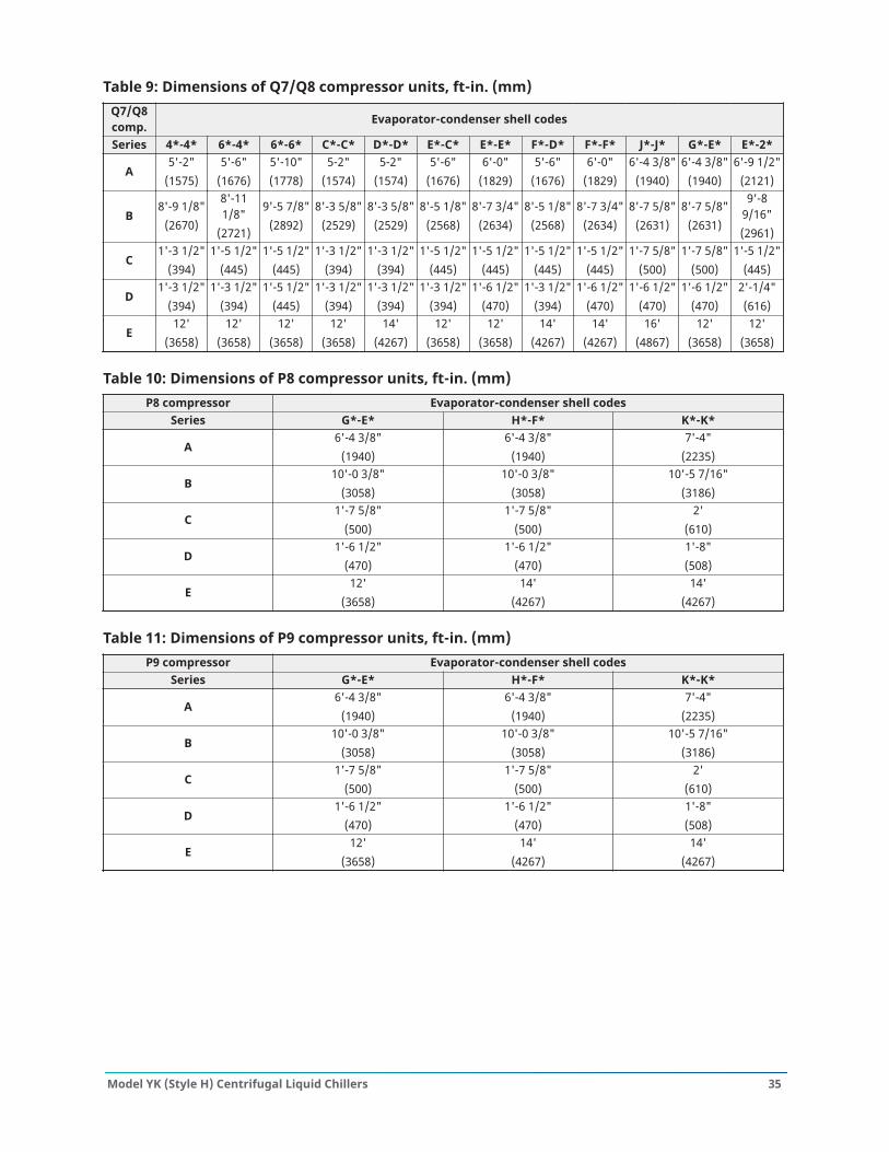
Table 9: Dimensions of Q7/Q8 compressor units, ft-in. (mm)Q7/Q8comp. Evaporator-condenser shell codes
Series 4*-4* 6*-4* 6*-6* C*-C* D*-D* E*-C* E*-E* F*-D* F*-F* J*-J* G*-E* E*-2*
A5'-2"
(1575)5'-6"
(1676)5'-10"(1778)
5-2"(1574)
5-2"(1574)
5'-6"(1676)
6'-0"(1829)
5'-6"(1676)
6'-0"(1829)
6'-4 3/8"(1940)
6'-4 3/8"(1940)
6'-9 1/2"(2121)
B8'-9 1/8"
(2670)
8'-111/8"
(2721)
9'-5 7/8"(2892)
8'-3 5/8"(2529)
8'-3 5/8"(2529)
8'-5 1/8"(2568)
8'-7 3/4"(2634)
8'-5 1/8"(2568)
8'-7 3/4"(2634)
8'-7 5/8"(2631)
8'-7 5/8"(2631)
9'-89/16"(2961)
C1'-3 1/2"
(394)1'-5 1/2"
(445)1'-5 1/2"
(445)1'-3 1/2"
(394)1'-3 1/2"
(394)1'-5 1/2"
(445)1'-5 1/2"
(445)1'-5 1/2"
(445)1'-5 1/2"
(445)1'-7 5/8"
(500)1'-7 5/8"
(500)1'-5 1/2"
(445)
D1'-3 1/2"
(394)1'-3 1/2"
(394)1'-5 1/2"
(445)1'-3 1/2"
(394)1'-3 1/2"
(394)1'-3 1/2"
(394)1'-6 1/2"
(470)1'-3 1/2"
(394)1'-6 1/2"
(470)1'-6 1/2"
(470)1'-6 1/2"
(470)2'-1/4"(616)
E12'
(3658)12'
(3658)12'
(3658)12'
(3658)14'
(4267)12'
(3658)12'
(3658)14'
(4267)14'
(4267)16'
(4867)12'
(3658)12'
(3658)
Table 10: Dimensions of P8 compressor units, ft-in. (mm)P8 compressor Evaporator-condenser shell codes
Series G*-E* H*-F* K*-K*
A6'-4 3/8"
(1940)6'-4 3/8"
(1940)7'-4"
(2235)
B10'-0 3/8"
(3058)10'-0 3/8"
(3058)10'-5 7/16"
(3186)
C1'-7 5/8"
(500)1'-7 5/8"
(500)2'
(610)
D1'-6 1/2"
(470)1'-6 1/2"
(470)1'-8"(508)
E12'
(3658)14'
(4267)14'
(4267)
Table 11: Dimensions of P9 compressor units, ft-in. (mm)P9 compressor Evaporator-condenser shell codes
Series G*-E* H*-F* K*-K*
A6'-4 3/8"
(1940)6'-4 3/8"
(1940)7'-4"
(2235)
B10'-0 3/8"
(3058)10'-0 3/8"
(3058)10'-5 7/16"
(3186)
C1'-7 5/8"
(500)1'-7 5/8"
(500)2'
(610)
D1'-6 1/2"
(470)1'-6 1/2"
(470)1'-8"(508)
E12'
(3658)14'
(4267)14'
(4267)
35Model YK (Style H) Centrifugal Liquid Chillers
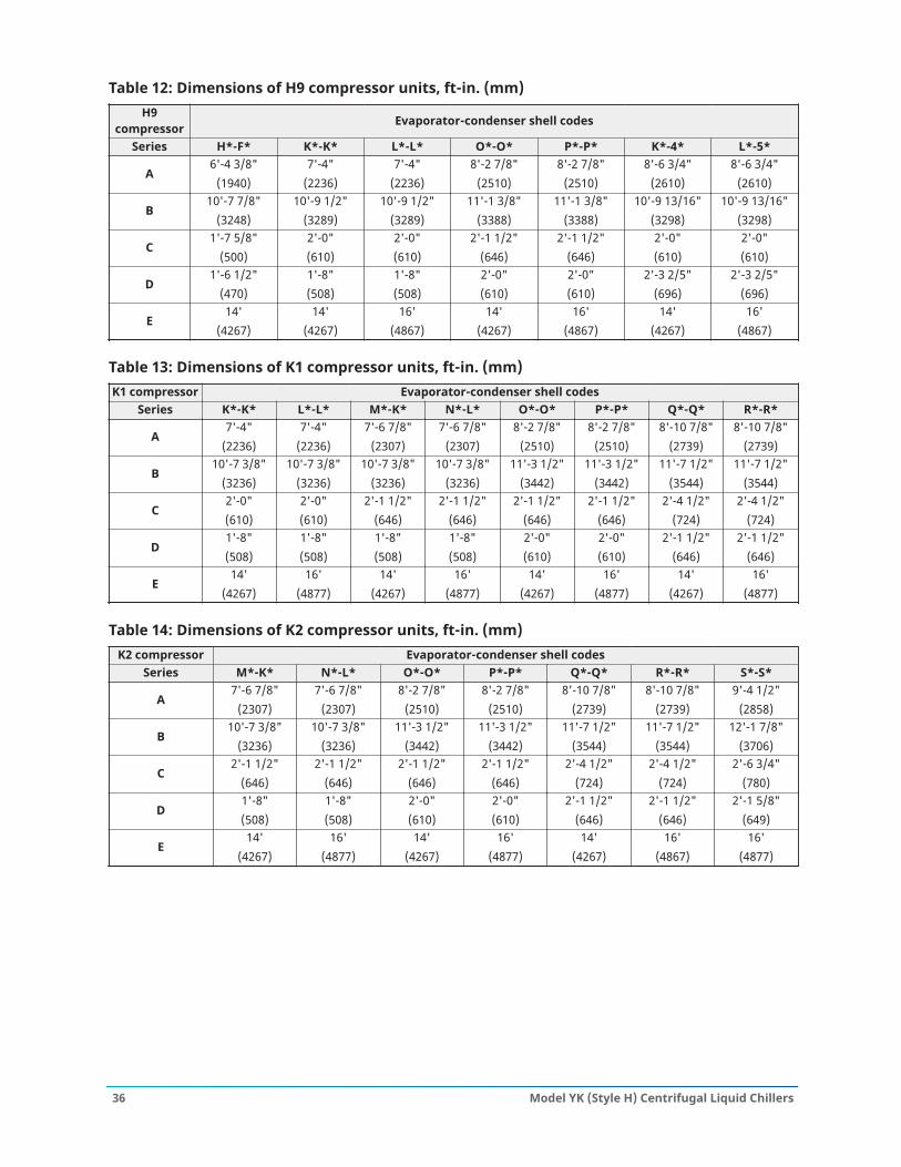
Table 12: Dimensions of H9 compressor units, ft-in. (mm)H9
compressor Evaporator-condenser shell codes
Series H*-F* K*-K* L*-L* O*-O* P*-P* K*-4* L*-5*
A6'-4 3/8"
(1940)7'-4"
(2236)7'-4"
(2236)8'-2 7/8"
(2510)8'-2 7/8"
(2510)8'-6 3/4"
(2610)8'-6 3/4"
(2610)
B10'-7 7/8"
(3248)10'-9 1/2"
(3289)10'-9 1/2"
(3289)11'-1 3/8"
(3388)11'-1 3/8"
(3388)10'-9 13/16"
(3298)10'-9 13/16"
(3298)
C1'-7 5/8"
(500)2'-0"(610)
2'-0"(610)
2'-1 1/2"(646)
2'-1 1/2"(646)
2'-0"(610)
2'-0"(610)
D1'-6 1/2"
(470)1'-8"(508)
1'-8"(508)
2'-0"(610)
2'-0"(610)
2'-3 2/5"(696)
2'-3 2/5"(696)
E14'
(4267)14'
(4267)16'
(4867)14'
(4267)16'
(4867)14'
(4267)16'
(4867)
Table 13: Dimensions of K1 compressor units, ft-in. (mm)K1 compressor Evaporator-condenser shell codes
Series K*-K* L*-L* M*-K* N*-L* O*-O* P*-P* Q*-Q* R*-R*
A7'-4"
(2236)7'-4"
(2236)7'-6 7/8"
(2307)7'-6 7/8"
(2307)8'-2 7/8"
(2510)8'-2 7/8"
(2510)8'-10 7/8"
(2739)8'-10 7/8"
(2739)
B10'-7 3/8"
(3236)10'-7 3/8"
(3236)10'-7 3/8"
(3236)10'-7 3/8"
(3236)11'-3 1/2"
(3442)11'-3 1/2"
(3442)11'-7 1/2"
(3544)11'-7 1/2"
(3544)
C2'-0"(610)
2'-0"(610)
2'-1 1/2"(646)
2'-1 1/2"(646)
2'-1 1/2"(646)
2'-1 1/2"(646)
2'-4 1/2"(724)
2'-4 1/2"(724)
D1'-8"(508)
1'-8"(508)
1'-8"(508)
1'-8"(508)
2'-0"(610)
2'-0"(610)
2'-1 1/2"(646)
2'-1 1/2"(646)
E14'
(4267)16'
(4877)14'
(4267)16'
(4877)14'
(4267)16'
(4877)14'
(4267)16'
(4877)
Table 14: Dimensions of K2 compressor units, ft-in. (mm)K2 compressor Evaporator-condenser shell codes
Series M*-K* N*-L* O*-O* P*-P* Q*-Q* R*-R* S*-S*
A7'-6 7/8"
(2307)7'-6 7/8"
(2307)8'-2 7/8"
(2510)8'-2 7/8"
(2510)8'-10 7/8"
(2739)8'-10 7/8"
(2739)9'-4 1/2"
(2858)
B10'-7 3/8"
(3236)10'-7 3/8"
(3236)11'-3 1/2"
(3442)11'-3 1/2"
(3442)11'-7 1/2"
(3544)11'-7 1/2"
(3544)12'-1 7/8"
(3706)
C2'-1 1/2"
(646)2'-1 1/2"
(646)2'-1 1/2"
(646)2'-1 1/2"
(646)2'-4 1/2"
(724)2'-4 1/2"
(724)2'-6 3/4"
(780)
D1'-8"(508)
1'-8"(508)
2'-0"(610)
2'-0"(610)
2'-1 1/2"(646)
2'-1 1/2"(646)
2'-1 5/8"(649)
E14'
(4267)16'
(4877)14'
(4267)16'
(4877)14'
(4267)16'
(4867)16'
(4877)
Model YK (Style H) Centrifugal Liquid Chillers36
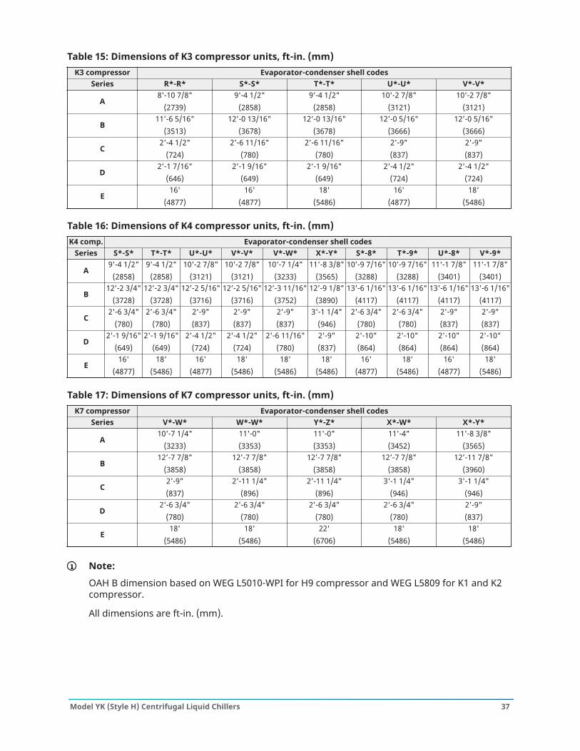
Table 15: Dimensions of K3 compressor units, ft-in. (mm)K3 compressor Evaporator-condenser shell codes
Series R*-R* S*-S* T*-T* U*-U* V*-V*
A8'-10 7/8"
(2739)9'-4 1/2"
(2858)9'-4 1/2"
(2858)10'-2 7/8"
(3121)10'-2 7/8"
(3121)
B11’-6 5/16"
(3513)12’-0 13/16"
(3678)12’-0 13/16"
(3678)12’-0 5/16"
(3666)12’-0 5/16"
(3666)
C2'-4 1/2"
(724)2'-6 11/16"
(780)2'-6 11/16"
(780)2'-9"(837)
2'-9"(837)
D2'-1 7/16"
(646)2'-1 9/16"
(649)2'-1 9/16"
(649)2'-4 1/2"
(724)2'-4 1/2"
(724)
E16'
(4877)16'
(4877)18'
(5486)16'
(4877)18'
(5486)
Table 16: Dimensions of K4 compressor units, ft-in. (mm)K4 comp. Evaporator-condenser shell codes
Series S*-S* T*-T* U*-U* V*-V* V*-W* X*-Y* S*-8* T*-9* U*-8* V*-9*
A9'-4 1/2"
(2858)9'-4 1/2"
(2858)10'-2 7/8"
(3121)10'-2 7/8"
(3121)10'-7 1/4"
(3233)11'-8 3/8"
(3565)10’-9 7/16"
(3288)10’-9 7/16"
(3288)11‘-1 7/8"
(3401)11‘-1 7/8"
(3401)
B12’-2 3/4"
(3728)12’-2 3/4"
(3728)12’-2 5/16"
(3716)12’-2 5/16"
(3716)12’-3 11/16"
(3752)12’-9 1/8"
(3890)13'-6 1/16"
(4117)13'-6 1/16"
(4117)13'-6 1/16"
(4117)13'-6 1/16"
(4117)
C2'-6 3/4"
(780)2'-6 3/4"
(780)2'-9"(837)
2'-9"(837)
2'-9"(837)
3'-1 1/4"(946)
2'-6 3/4"(780)
2'-6 3/4"(780)
2'-9"(837)
2'-9"(837)
D2'-1 9/16"
(649)2'-1 9/16"
(649)2'-4 1/2"
(724)2'-4 1/2"
(724)2'-6 11/16"
(780)2'-9"(837)
2'-10"(864)
2'-10"(864)
2'-10"(864)
2'-10"(864)
E16'
(4877)18'
(5486)16'
(4877)18'
(5486)18'
(5486)18'
(5486)16'
(4877)18'
(5486)16'
(4877)18'
(5486)
Table 17: Dimensions of K7 compressor units, ft-in. (mm)K7 compressor Evaporator-condenser shell codes
Series V*-W* W*-W* Y*-Z* X*-W* X*-Y*
A10'-7 1/4"
(3233)11'-0"(3353)
11'-0"(3353)
11'-4"(3452)
11'-8 3/8"(3565)
B12’-7 7/8"
(3858)12’-7 7/8"
(3858)12’-7 7/8"
(3858)12’-7 7/8"
(3858)12’-11 7/8"
(3960)
C2'-9"(837)
2'-11 1/4"(896)
2'-11 1/4"(896)
3'-1 1/4"(946)
3'-1 1/4"(946)
D2'-6 3/4"
(780)2'-6 3/4"
(780)2'-6 3/4"
(780)2'-6 3/4"
(780)2'-9"(837)
E18'
(5486)18'
(5486)22'
(6706)18'
(5486)18'
(5486)
Note:
OAH B dimension based on WEG L5010-WPI for H9 compressor and WEG L5809 for K1 and K2compressor.
All dimensions are ft-in. (mm).
37Model YK (Style H) Centrifugal Liquid Chillers
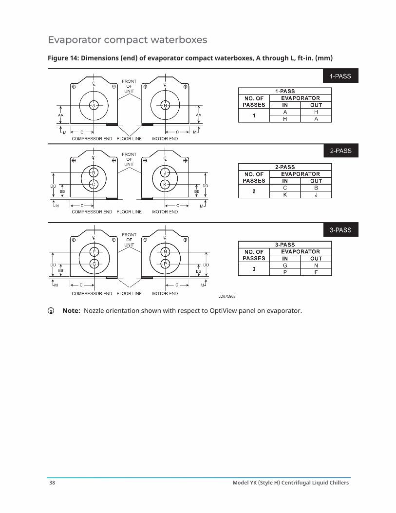
Evaporator compact waterboxes
Figure 14: Dimensions (end) of evaporator compact waterboxes, A through L, ft-in. (mm)
Note: Nozzle orientation shown with respect to OptiView panel on evaporator.
Model YK (Style H) Centrifugal Liquid Chillers38
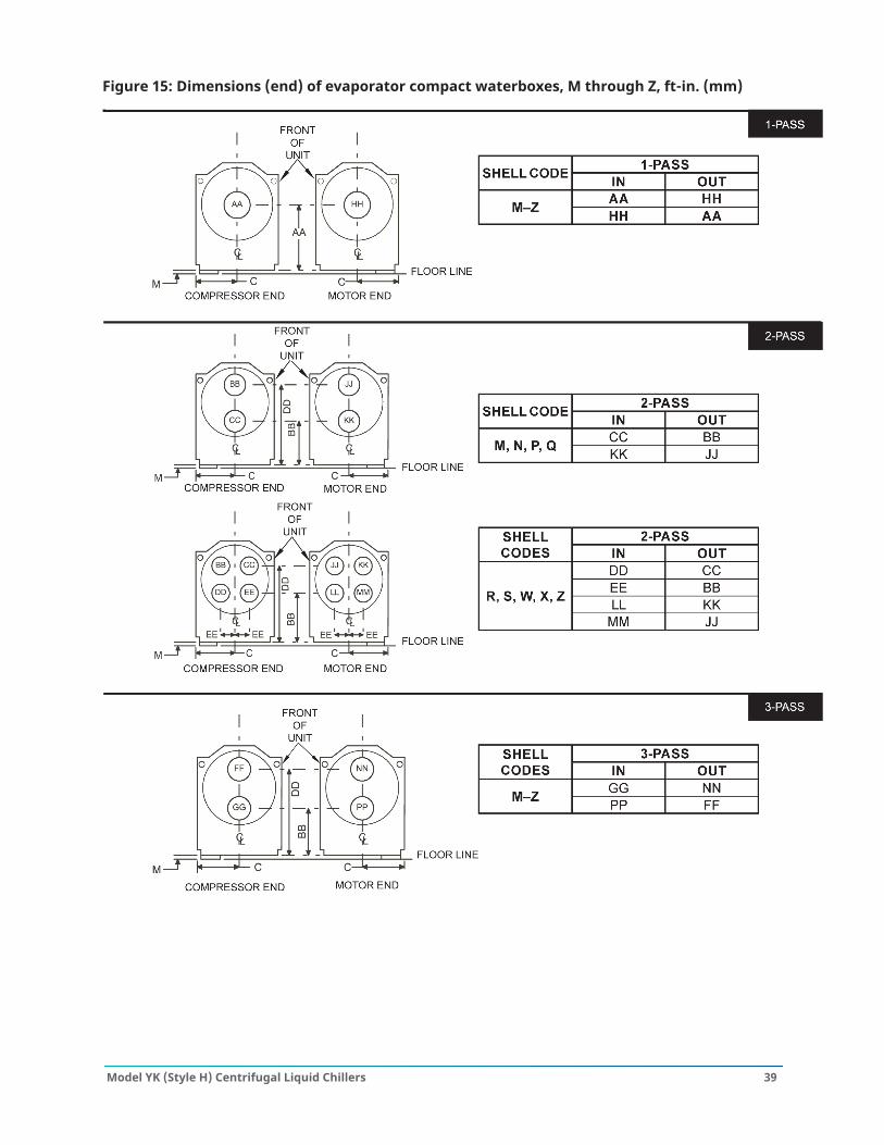
Figure 15: Dimensions (end) of evaporator compact waterboxes, M through Z, ft-in. (mm)
39Model YK (Style H) Centrifugal Liquid Chillers
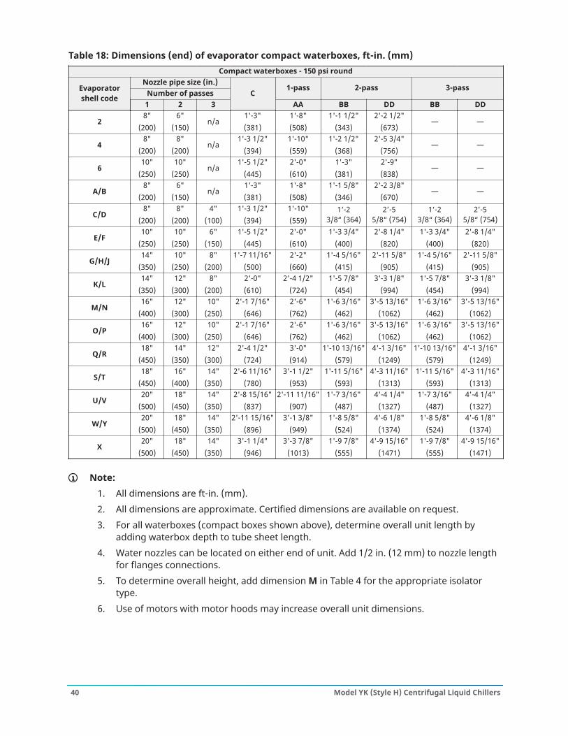
Table 18: Dimensions (end) of evaporator compact waterboxes, ft-in. (mm)Compact waterboxes - 150 psi round
Nozzle pipe size (in.)Number of passes
1-pass 2-pass 3-passEvaporatorshell code
1 2 3C
AA BB DD BB DD
28"
(200)6"
(150)n/a
1'-3"(381)
1'-8"(508)
1'-1 1/2"(343)
2'-2 1/2"(673)
— —
48"
(200)8"
(200)n/a
1'-3 1/2"(394)
1'-10"(559)
1'-2 1/2"(368)
2'-5 3/4"(756)
— —
610"
(250)10"
(250)n/a
1'-5 1/2"(445)
2'-0"(610)
1'-3"(381)
2'-9"(838)
— —
A/B8"
(200)6"
(150)n/a
1'-3"(381)
1'-8"(508)
1'-1 5/8"(346)
2'-2 3/8"(670)
— —
C/D8"
(200)8"
(200)4"
(100)1'-3 1/2"
(394)1'-10"(559)
1‘-23/8“ (364)
2’-55/8“ (754)
1‘-23/8“ (364)
2’-55/8“ (754)
E/F10"
(250)10"
(250)6"
(150)1'-5 1/2"
(445)2'-0"(610)
1'-3 3/4"(400)
2'-8 1/4"(820)
1'-3 3/4"(400)
2'-8 1/4"(820)
G/H/J14"
(350)10"
(250)8"
(200)1'-7 11/16"
(500)2'-2"(660)
1'-4 5/16"(415)
2'-11 5/8"(905)
1'-4 5/16"(415)
2'-11 5/8"(905)
K/L14"
(350)12"
(300)8"
(200)2'-0"(610)
2'-4 1/2"(724)
1'-5 7/8"(454)
3'-3 1/8"(994)
1'-5 7/8"(454)
3'-3 1/8"(994)
M/N16"
(400)12"
(300)10"
(250)2'-1 7/16"
(646)2'-6"(762)
1'-6 3/16"(462)
3'-5 13/16"(1062)
1'-6 3/16"(462)
3'-5 13/16"(1062)
O/P16"
(400)12"
(300)10"
(250)2'-1 7/16"
(646)2'-6"(762)
1'-6 3/16"(462)
3'-5 13/16"(1062)
1'-6 3/16"(462)
3'-5 13/16"(1062)
Q/R18"
(450)14"
(350)12"
(300)2'-4 1/2"
(724)3'-0"(914)
1'-10 13/16"(579)
4'-1 3/16"(1249)
1'-10 13/16"(579)
4'-1 3/16"(1249)
S/T18"
(450)16"
(400)14"
(350)2'-6 11/16"
(780)3'-1 1/2"
(953)1'-11 5/16"
(593)4'-3 11/16"
(1313)1'-11 5/16"
(593)4'-3 11/16"
(1313)
U/V20"
(500)18"
(450)14"
(350)2'-8 15/16"
(837)2'-11 11/16"
(907)1'-7 3/16"
(487)4'-4 1/4"
(1327)1'-7 3/16"
(487)4'-4 1/4"
(1327)
W/Y20"
(500)18"
(450)14"
(350)2'-11 15/16"
(896)3'-1 3/8"
(949)1'-8 5/8"
(524)4'-6 1/8"
(1374)1'-8 5/8"
(524)4'-6 1/8"
(1374)
X20"
(500)18"
(450)14"
(350)3'-1 1/4"
(946)3'-3 7/8"
(1013)1'-9 7/8"
(555)4'-9 15/16"
(1471)1'-9 7/8"
(555)4'-9 15/16"
(1471)
Note:1. All dimensions are ft-in. (mm).2. All dimensions are approximate. Certified dimensions are available on request.3. For all waterboxes (compact boxes shown above), determine overall unit length by
adding waterbox depth to tube sheet length.4. Water nozzles can be located on either end of unit. Add 1/2 in. (12 mm) to nozzle length
for flanges connections.5. To determine overall height, add dimension M in Table 4 for the appropriate isolator
type.6. Use of motors with motor hoods may increase overall unit dimensions.
Model YK (Style H) Centrifugal Liquid Chillers40
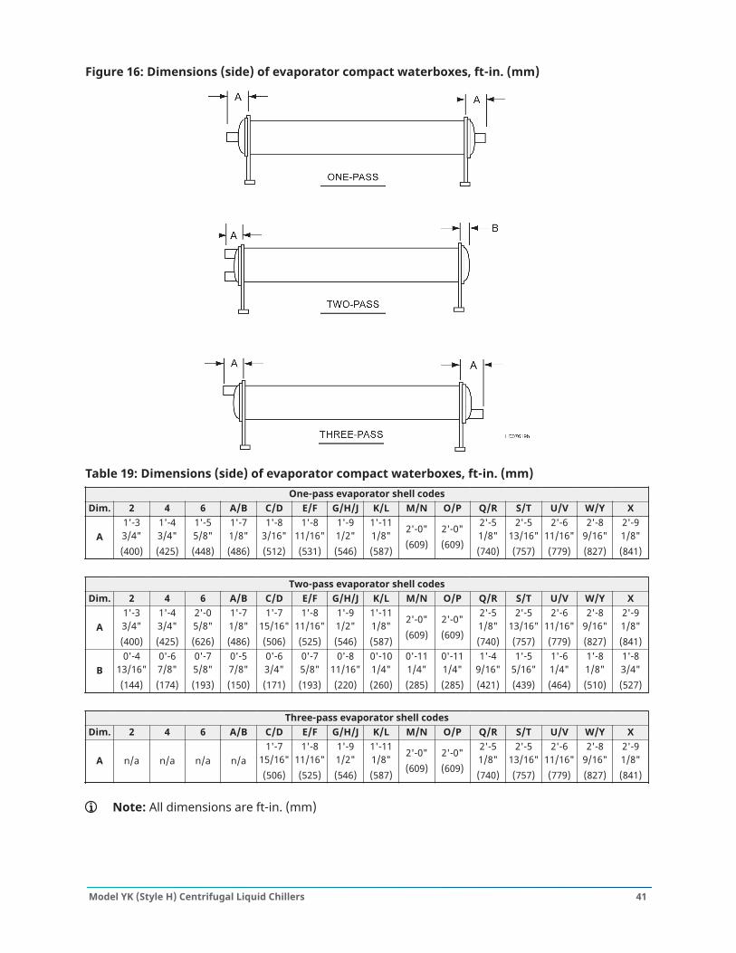
Figure 16: Dimensions (side) of evaporator compact waterboxes, ft-in. (mm)
Table 19: Dimensions (side) of evaporator compact waterboxes, ft-in. (mm)One-pass evaporator shell codes
Dim. 2 4 6 A/B C/D E/F G/H/J K/L M/N O/P Q/R S/T U/V W/Y X
A1'-33/4"(400)
1'-43/4"(425)
1'-55/8"(448)
1'-71/8"(486)
1'-83/16"(512)
1'-811/16"(531)
1'-91/2"(546)
1'-111/8"(587)
2'-0"(609)
2'-0"(609)
2'-51/8"(740)
2'-513/16"(757)
2'-611/16"(779)
2'-89/16"(827)
2'-91/8"(841)
Two-pass evaporator shell codesDim. 2 4 6 A/B C/D E/F G/H/J K/L M/N O/P Q/R S/T U/V W/Y X
A1'-33/4"(400)
1'-43/4"(425)
2'-05/8"(626)
1'-71/8"(486)
1'-715/16"(506)
1'-811/16"(525)
1'-91/2"(546)
1'-111/8"(587)
2'-0"(609)
2'-0"(609)
2'-51/8"(740)
2'-513/16"(757)
2'-611/16"(779)
2'-89/16"(827)
2'-91/8"(841)
B0'-4
13/16"(144)
0'-67/8"(174)
0'-75/8"(193)
0'-57/8"(150)
0'-63/4"(171)
0'-75/8"(193)
0'-811/16"(220)
0'-101/4"(260)
0'-111/4"(285)
0'-111/4"(285)
1'-49/16"(421)
1'-55/16"(439)
1'-61/4"(464)
1'-81/8"(510)
1'-83/4"(527)
Three-pass evaporator shell codesDim. 2 4 6 A/B C/D E/F G/H/J K/L M/N O/P Q/R S/T U/V W/Y X
A n/a n/a n/a n/a1'-7
15/16"(506)
1'-811/16"(525)
1'-91/2"(546)
1'-111/8"(587)
2'-0"(609)
2'-0"(609)
2'-51/8"(740)
2'-513/16"(757)
2'-611/16"(779)
2'-89/16"(827)
2'-91/8"(841)
Note: All dimensions are ft-in. (mm)
41Model YK (Style H) Centrifugal Liquid Chillers
Condenser compact waterboxes
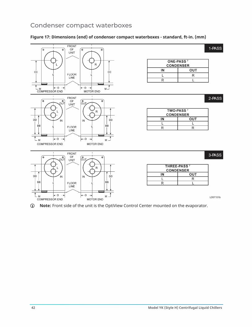
Figure 17: Dimensions (end) of condenser compact waterboxes - standard, ft-in. (mm)
Note: Front side of the unit is the OptiView Control Center mounted on the evaporator.
Model YK (Style H) Centrifugal Liquid Chillers42
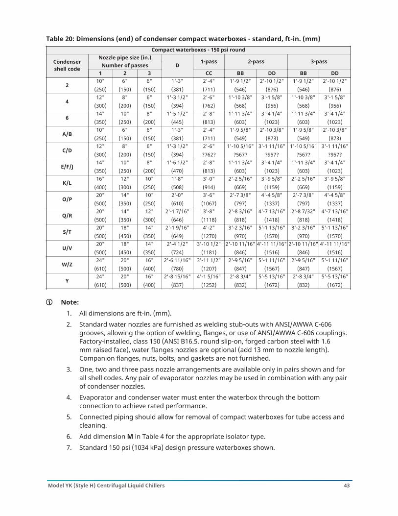
Table 20: Dimensions (end) of condenser compact waterboxes - standard, ft-in. (mm)Compact waterboxes - 150 psi round
Nozzle pipe size (in.)Number of passes
1-pass 2-pass 3-passCondensershell code
1 2 3D
CC BB DD BB DD
210"
(250)6"
(150)6"
(150)1'-3"(381)
2'-4"(711)
1'-9 1/2"(546)
2'-10 1/2"(876)
1'-9 1/2"(546)
2'-10 1/2"(876)
412"
(300)8"
(200)6"
(150)1'-3 1/2"
(394)2'-6"(762)
1'-10 3/8"(568)
3'-1 5/8"(956)
1'-10 3/8"(568)
3'-1 5/8"(956)
614"
(350)10"
(250)8"
(200)1'-5 1/2"
(445)2'-8"(813)
1'-11 3/4"(603)
3'-4 1/4"(1023)
1'-11 3/4"(603)
3'-4 1/4"(1023)
A/B10"
(250)6"
(150)6"
(150)1'-3"(381)
2'-4"(711)
1'-9 5/8"(549)
2'-10 3/8"(873)
1'-9 5/8"(549)
2'-10 3/8"(873)
C/D12"
(300)8"
(200)6"
(150)1'-3 1/2"
(394)2'-6"‑762‑
1'-10 5/16"‑567‑
3'-1 11/16"‑957‑
1'-10 5/16"‑567‑
3'-1 11/16"‑957‑
E/F/J14"
(350)10"
(250)8"
(200)1'-6 1/2"
(470)2'-8"(813)
1'-11 3/4"(603)
3'-4 1/4"(1023)
1'-11 3/4"(603)
3'-4 1/4"(1023)
K/L16"
(400)12"
(300)10"
(250)1'-8"(508)
3'-0"(914)
2'-2 5/16"(669)
3'-9 5/8"(1159)
2'-2 5/16"(669)
3'-9 5/8"(1159)
O/P20"
(500)14"
(350)10"
(250)2'-0"(610)
3'-6"(1067)
2'-7 3/8"(797)
4'-4 5/8"(1337)
2'-7 3/8"(797)
4'-4 5/8"(1337)
Q/R20"
(500)14"
(350)12"
(300)2'-1 7/16"
(646)3'-8"
(1118)2'-8 3/16"
(818)4'-7 13/16"
(1418)2'-8 7/32"
(818)4'-7 13/16"
(1418)
S/T20"
(500)18"
(450)14"
(350)2'-1 9/16"
(649)4'-2"
(1270)3'-2 3/16"
(970)5'-1 13/16"
(1570)3'-2 3/16"
(970)5'-1 13/16"
(1570)
U/V20"
(500)18"
(450)14"
(350)2'-4 1/2"
(724)3'-10 1/2"
(1181)2'-10 11/16"
(846)4'-11 11/16"
(1516)2'-10 11/16"
(846)4'-11 11/16"
(1516)
W/Z24"
(610)20"
(500)16"
(400)2'-6 11/16"
(780)3'-11 1/2"
(1207)2'-9 5/16"
(847)5'-1 11/16"
(1567)2'-9 5/16"
(847)5'-1 11/16"
(1567)
Y24"
(610)20"
(500)16"
(400)2'-8 15/16"
(837)4'-1 5/16"
(1252)2'-8 3/4"
(832)5'-5 13/16"
(1672)2'-8 3/4"
(832)5'-5 13/16"
(1672)
Note:1. All dimensions are ft-in. (mm).2. Standard water nozzles are furnished as welding stub-outs with ANSI/AWWA C-606
grooves, allowing the option of welding, flanges, or use of ANSI/AWWA C-606 couplings.Factory-installed, class 150 (ANSI B16.5, round slip-on, forged carbon steel with 1.6mm raised face), water flanges nozzles are optional (add 13 mm to nozzle length).Companion flanges, nuts, bolts, and gaskets are not furnished.
3. One, two and three pass nozzle arrangements are available only in pairs shown and forall shell codes. Any pair of evaporator nozzles may be used in combination with any pairof condenser nozzles.
4. Evaporator and condenser water must enter the waterbox through the bottomconnection to achieve rated performance.
5. Connected piping should allow for removal of compact waterboxes for tube access andcleaning.
6. Add dimension M in Table 4 for the appropriate isolator type.7. Standard 150 psi (1034 kPa) design pressure waterboxes shown.
43Model YK (Style H) Centrifugal Liquid Chillers
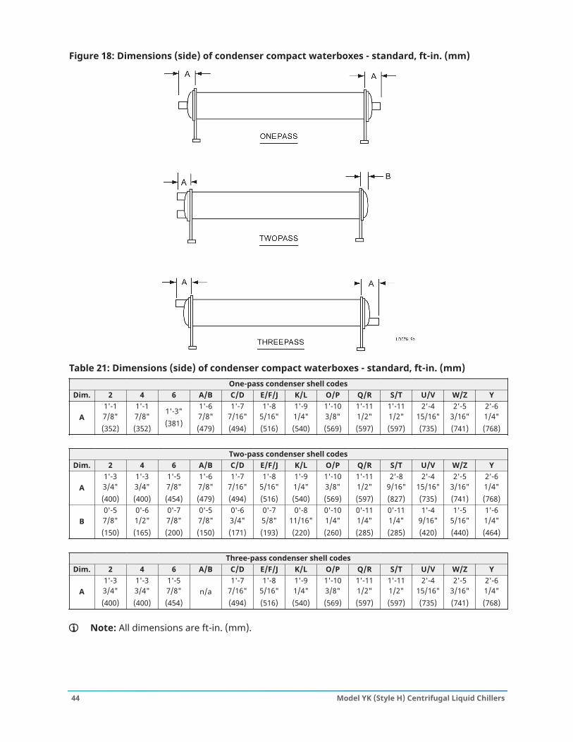
Figure 18: Dimensions (side) of condenser compact waterboxes - standard, ft-in. (mm)
Table 21: Dimensions (side) of condenser compact waterboxes - standard, ft-in. (mm)One-pass condenser shell codes
Dim. 2 4 6 A/B C/D E/F/J K/L O/P Q/R S/T U/V W/Z Y
A1'-17/8"(352)
1'-17/8"(352)
1'-3"(381)
1'-67/8"(479)
1'-77/16"(494)
1'-85/16"(516)
1'-91/4"(540)
1'-103/8"(569)
1'-111/2"(597)
1'-111/2"(597)
2'-415/16"(735)
2'-53/16"(741)
2'-61/4"(768)
Two-pass condenser shell codesDim. 2 4 6 A/B C/D E/F/J K/L O/P Q/R S/T U/V W/Z Y
A1'-33/4"(400)
1'-33/4"(400)
1'-57/8"(454)
1'-67/8"(479)
1'-77/16"(494)
1'-85/16"(516)
1'-91/4"(540)
1'-103/8"(569)
1'-111/2"(597)
2'-89/16"(827)
2'-415/16"(735)
2'-53/16"(741)
2'-61/4"(768)
B0'-57/8"(150)
0'-61/2"(165)
0'-77/8"(200)
0'-57/8"(150)
0'-63/4"(171)
0'-75/8"(193)
0'-811/16"(220)
0'-101/4"(260)
0'-111/4"(285)
0'-111/4"(285)
1'-49/16"(420)
1'-55/16"(440)
1'-61/4"(464)
Three-pass condenser shell codesDim. 2 4 6 A/B C/D E/F/J K/L O/P Q/R S/T U/V W/Z Y
A1'-33/4"(400)
1'-33/4"(400)
1'-57/8"(454)
n/a1'-7
7/16"(494)
1'-85/16"(516)
1'-91/4"(540)
1'-103/8"(569)
1'-111/2"(597)
1'-111/2"(597)
2'-415/16"(735)
2'-53/16"(741)
2'-61/4"(768)
Note: All dimensions are ft-in. (mm).
Model YK (Style H) Centrifugal Liquid Chillers44
Condenser heat recovery compact waterboxes
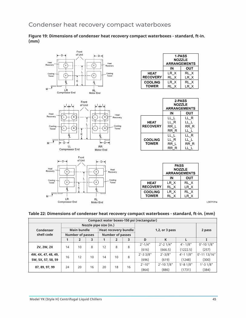
Figure 19: Dimensions of condenser heat recovery compact waterboxes - standard, ft-in.(mm)
Table 22: Dimensions of condenser heat recovery compact waterboxes - standard, ft-in. (mm)Compact water boxes-150 psi (rectangular)
Nozzle pipe size (in.)Main bundle Heat recovery bundle
Number of passes Number of passes1,2, or 3 pass 2 passCondenser
shell code1 2 3 1 2 3 D K L I
2V, 2W, 2X 14 10 8 12 8 82'-1/4"(616)
2'-2 1/4"(666.5)
4'- 1/8"(1222.5)
0'-10 1/8"(257)
4W, 4X, 47, 48, 49,5W, 5X, 57, 58, 59
16 12 10 14 10 82'-3 3/8"
(696)2'-3/8"(619)
4'-1 1/8"(1248)
0'-11 13/16"(300)
87, 89, 97, 99 24 20 16 20 18 162'-10"(864)
2'-10 7/8"(886)
5'-8 1/8"(1731)
1'-3 1/8"(384)
45Model YK (Style H) Centrifugal Liquid Chillers
Evaporator marine waterboxes
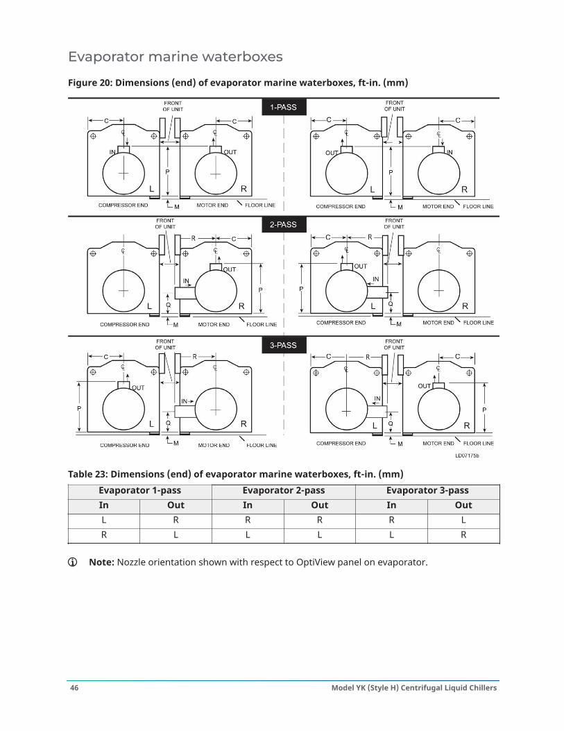
Figure 20: Dimensions (end) of evaporator marine waterboxes, ft-in. (mm)
Table 23: Dimensions (end) of evaporator marine waterboxes, ft-in. (mm)Evaporator 1-pass Evaporator 2-pass Evaporator 3-passIn Out In Out In OutL R R R R LR L L L L R
Note: Nozzle orientation shown with respect to OptiView panel on evaporator.
Model YK (Style H) Centrifugal Liquid Chillers46
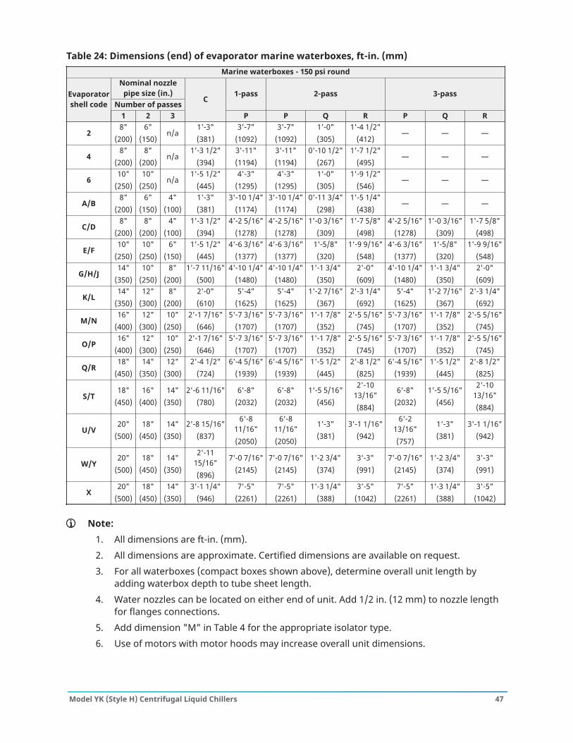
Table 24: Dimensions (end) of evaporator marine waterboxes, ft-in. (mm)Marine waterboxes - 150 psi round
Nominal nozzlepipe size (in.)
Number of passes1-pass 2-pass 3-passEvaporator
shell code1 2 3
C
P P Q R P Q R
28"
(200)6"
(150)n/a
1'-3"(381)
3'-7"(1092)
3'-7"(1092)
1'-0"(305)
1'-4 1/2"(412)
— — —
48"
(200)8"
(200)n/a
1'-3 1/2"(394)
3'-11"(1194)
3'-11"(1194)
0'-10 1/2"(267)
1'-7 1/2"(495)
— — —
610"
(250)10"
(250)n/a
1'-5 1/2"(445)
4'-3"(1295)
4'-3"(1295)
1'-0"(305)
1'-9 1/2"(546)
— — —
A/B8"
(200)6"
(150)4"
(100)1'-3"(381)
3'-10 1/4"(1174)
3'-10 1/4"(1174)
0'-11 3/4"(298)
1'-5 1/4"(438)
— — —
C/D8"
(200)8"
(200)4"
(100)1'-3 1/2"
(394)4'-2 5/16"
(1278)4'-2 5/16"
(1278)1'-0 3/16"
(309)1'-7 5/8"
(498)4'-2 5/16"
(1278)1'-0 3/16"
(309)1'-7 5/8"
(498)
E/F10"
(250)10"
(250)6"
(150)1'-5 1/2"
(445)4'-6 3/16"
(1377)4'-6 3/16"
(1377)1'-5/8"(320)
1'-9 9/16"(548)
4'-6 3/16"(1377)
1'-5/8"(320)
1'-9 9/16"(548)
G/H/J14"
(350)10"
(250)8"
(200)1'-7 11/16"
(500)4'-10 1/4"
(1480)4'-10 1/4"
(1480)1'-1 3/4"
(350)2'-0"(609)
4'-10 1/4"(1480)
1'-1 3/4"(350)
2'-0"(609)
K/L14"
(350)12"
(300)8"
(200)2'-0"(610)
5'-4"(1625)
5'-4"(1625)
1'-2 7/16"(367)
2'-3 1/4"(692)
5'-4"(1625)
1'-2 7/16"(367)
2'-3 1/4"(692)
M/N16"
(400)12"
(300)10"
(250)2'-1 7/16"
(646)5'-7 3/16"
(1707)5'-7 3/16"
(1707)1'-1 7/8"
(352)2'-5 5/16"
(745)5'-7 3/16"
(1707)1'-1 7/8"
(352)2'-5 5/16"
(745)
O/P16"
(400)12"
(300)10"
(250)2'-1 7/16"
(646)5'-7 3/16"
(1707)5'-7 3/16"
(1707)1'-1 7/8"
(352)2'-5 5/16"
(745)5'-7 3/16"
(1707)1'-1 7/8"
(352)2'-5 5/16"
(745)
Q/R18"
(450)14"
(350)12"
(300)2'-4 1/2"
(724)6'-4 5/16"
(1939)6'-4 5/16"
(1939)1'-5 1/2"
(445)2'-8 1/2"
(825)6'-4 5/16"
(1939)1'-5 1/2"
(445)2'-8 1/2"
(825)
S/T18"
(450)16"
(400)14"
(350)2'-6 11/16"
(780)6'-8"
(2032)6'-8"
(2032)1'-5 5/16"
(456)
2'-1013/16"(884)
6'-8"(2032)
1'-5 5/16"(456)
2'-1013/16"(884)
U/V20"
(500)18"
(450)14"
(350)2'-8 15/16"
(837)
6'-811/16"(2050)
6'-811/16"(2050)
1'-3"(381)
3'-1 1/16"(942)
6'-213/16"(757)
1'-3"(381)
3'-1 1/16"(942)
W/Y20"
(500)18"
(450)14"
(350)
2'-1115/16"(896)
7'-0 7/16"(2145)
7'-0 7/16"(2145)
1'-2 3/4"(374)
3'-3"(991)
7'-0 7/16"(2145)
1'-2 3/4"(374)
3'-3"(991)
X20"
(500)18"
(450)14"
(350)3'-1 1/4"
(946)7'-5"
(2261)7'-5"
(2261)1'-3 1/4"
(388)3'-5"
(1042)7'-5"
(2261)1'-3 1/4"
(388)3'-5"
(1042)
Note:1. All dimensions are ft-in. (mm).2. All dimensions are approximate. Certified dimensions are available on request.3. For all waterboxes (compact boxes shown above), determine overall unit length by
adding waterbox depth to tube sheet length.4. Water nozzles can be located on either end of unit. Add 1/2 in. (12 mm) to nozzle length
for flanges connections.5. Add dimension "M" in Table 4 for the appropriate isolator type.6. Use of motors with motor hoods may increase overall unit dimensions.
47Model YK (Style H) Centrifugal Liquid Chillers
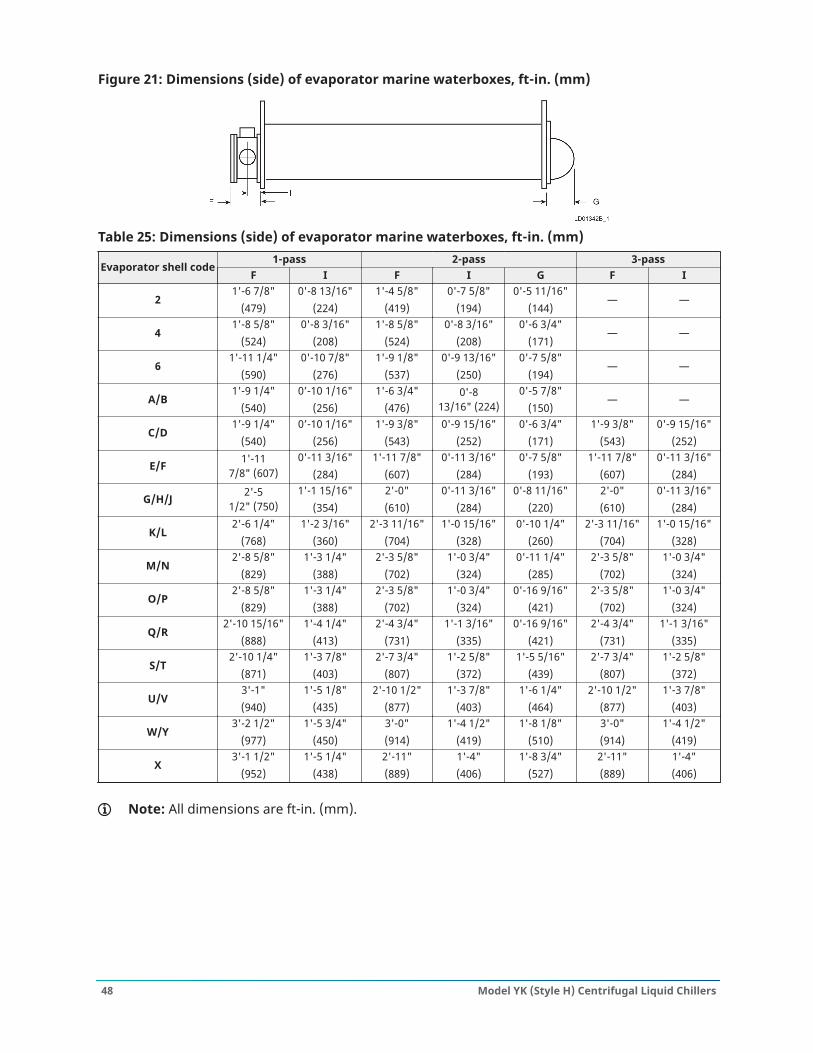
Figure 21: Dimensions (side) of evaporator marine waterboxes, ft-in. (mm)
Table 25: Dimensions (side) of evaporator marine waterboxes, ft-in. (mm)1-pass 2-pass 3-pass
Evaporator shell codeF I F I G F I
21'-6 7/8"
(479)0'-8 13/16"
(224)1'-4 5/8"
(419)0'-7 5/8"
(194)0'-5 11/16"
(144)— —
41'-8 5/8"
(524)0'-8 3/16"
(208)1'-8 5/8"
(524)0'-8 3/16"
(208)0'-6 3/4"
(171)— —
61'-11 1/4"
(590)0'-10 7/8"
(276)1'-9 1/8"
(537)0'-9 13/16"
(250)0'-7 5/8"
(194)— —
A/B1'-9 1/4"
(540)0’-10 1/16"
(256)1'-6 3/4"
(476)0'-8
13/16" (224)0'-5 7/8"
(150)— —
C/D1'-9 1/4"
(540)0’-10 1/16"
(256)1'-9 3/8"
(543)0'-9 15/16"
(252)0'-6 3/4"
(171)1'-9 3/8"
(543)0'-9 15/16"
(252)
E/F 1'-117/8" (607)
0'-11 3/16"(284)
1'-11 7/8"(607)
0'-11 3/16"(284)
0'-7 5/8"(193)
1'-11 7/8"(607)
0'-11 3/16"(284)
G/H/J 2'-51/2" (750)
1'-1 15/16"(354)
2'-0"(610)
0'-11 3/16"(284)
0'-8 11/16"(220)
2'-0"(610)
0'-11 3/16"(284)
K/L2'-6 1/4"
(768)1'-2 3/16"
(360)2'-3 11/16"
(704)1'-0 15/16"
(328)0'-10 1/4"
(260)2'-3 11/16"
(704)1'-0 15/16"
(328)
M/N2'-8 5/8"
(829)1'-3 1/4"
(388)2'-3 5/8"
(702)1'-0 3/4"
(324)0'-11 1/4"
(285)2'-3 5/8"
(702)1'-0 3/4"
(324)
O/P2'-8 5/8"
(829)1'-3 1/4"
(388)2'-3 5/8"
(702)1'-0 3/4"
(324)0'-16 9/16"
(421)2'-3 5/8"
(702)1'-0 3/4"
(324)
Q/R2'-10 15/16"
(888)1'-4 1/4"
(413)2'-4 3/4"
(731)1'-1 3/16"
(335)0'-16 9/16"
(421)2'-4 3/4"
(731)1'-1 3/16"
(335)
S/T2'-10 1/4"
(871)1'-3 7/8"
(403)2'-7 3/4"
(807)1'-2 5/8"
(372)1'-5 5/16"
(439)2'-7 3/4"
(807)1'-2 5/8"
(372)
U/V3'-1"(940)
1'-5 1/8"(435)
2'-10 1/2"(877)
1'-3 7/8"(403)
1'-6 1/4"(464)
2'-10 1/2"(877)
1'-3 7/8"(403)
W/Y3'-2 1/2"
(977)1'-5 3/4"
(450)3'-0"(914)
1'-4 1/2"(419)
1'-8 1/8"(510)
3'-0"(914)
1'-4 1/2"(419)
X3'-1 1/2"
(952)1'-5 1/4"
(438)2'-11"(889)
1'-4"(406)
1'-8 3/4"(527)
2'-11"(889)
1'-4"(406)
Note: All dimensions are ft-in. (mm).
Model YK (Style H) Centrifugal Liquid Chillers48
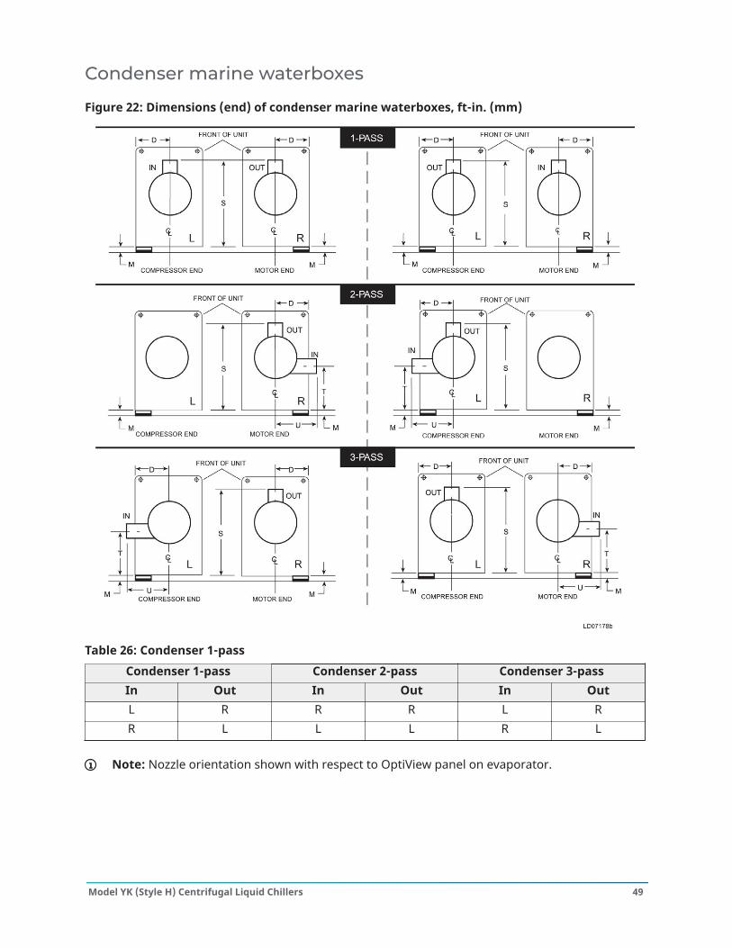
Condenser marine waterboxes
Figure 22: Dimensions (end) of condenser marine waterboxes, ft-in. (mm)
Table 26: Condenser 1-passCondenser 1-pass Condenser 2-pass Condenser 3-passIn Out In Out In OutL R R R L RR L L L R L
Note: Nozzle orientation shown with respect to OptiView panel on evaporator.
49Model YK (Style H) Centrifugal Liquid Chillers
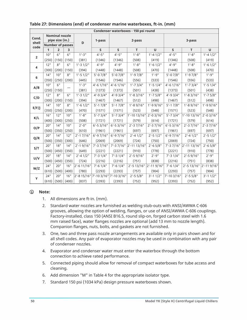
Table 27: Dimensions (end) of condenser marine waterboxes, ft-in. (mm)Condenser waterboxes - 150 psi round
Nominal nozzlepipe size (in.)
Number of passes1-pass 2-pass 3-passCond.
shellcode
1 2 3
D
S S T U S T U
210"
(250)6"
(150)6"
(150)1'-3"(381)
4'-5"(1346)
4'-5"(1346)
1'-8"(508)
1'-4 1/2"(419)
4'-5"(1346)
1'-8"(508)
1'-4 1/2"(419)
412"
(300)8"
(200)6"
(150)1'-3 1/2"
(394)4'-9"
(1448)4'-9"
(1448)1'-8"(508)
1'-6 1/2"(470)
4'-9"(1448)
1'-8"(508)
1'-6 1/2"(470)
614"
(350)10"
(250)8"
(200)1'-5 1/2"
(445)5'-0 7/8"
(1546)5'-0 7/8"
(1546)1'-9 7/8"
(556)1'-9"(533)
5'-0 7/8"(1546)
1'-9 7/8"(556)
1'-9"(533)
A/B10"
(250)6"
(150)—
1'-3"(381)
4'-6 1/16"(1373)
4'-6 1/16"(1373)
1'-7 3/4"(501)
1'-5 1/4"(438)
4'-6 1/16"(1373)
1'-7 3/4"(501)
1'-5 1/4"(438)
C/D12"
(300)8"
(200)6"
(150)1'-3 1/2"
(394)4'-9 3/4"
(1467)4'-9 3/4"
(1467)1'-8 3/16"
(512)1'-7 5/8"
(498)4'-9 3/4"
(1467)1'-8 3/16"
(512)1'-7 5/8"
(498)
E/F/J14"
(350)10"
(250)8"
(200)1'-6 1/2"
(470)5'-1 7/8"
(1571)5'-1 7/8"
(1571)1'-8 9/16"
(523)1'-9 9/16"
(548)5'-1 7/8"
(1571)1'-8 9/16"
(523)1'-9 9/16"
(548)
K/L16"
(400)12"
(300)10"
(250)1'-8"(508)
5'-7 3/4"(1721)
5'-7 3/4"(1721)
1'-10 13/16"(579)
2'-0 3/16"(614)
5'-7 3/4"(1721)
1'-10 13/16"(579)
2'-0 3/16"(614)
O/P20"
(500)14"
(350)10"
(250)2'-0"(610)
6'-5 3/16"(1961)
6'-5 3/16"(1961)
2'-3 7/16"(697)
2'-3 7/16"(697)
6'-5 3/16"(1961)
2'-3 7/16"(697)
2'-3 7/16"(697)
Q/R20"
(500)14"
(350)12"
(300)2'-1 7/16"
(646)6'-9 7/16"
(2069)6'-9 7/16"
(2069)2'-4 1/2"
(724)2'-5 1/2"
(750)6'-9 7/16"
(2069)2'-4 1/2"
(724)2'-5 1/2"
(750)
S/T20"
(500)18"
(450)14"
(350)2'-1 9/16"
(649)7'-3 7/16"
(2221)7'-3 7/16"
(2221)2'-11 13/16"
(910)2'-6 5/8"
(778)7'-3 7/16"
(2221)2'-11 13/16"
(910)2'-6 5/8"
(778)
U/V20"
(500)18"
(450)14"
(350)2'-4 1/2"
(724)7'-3 1/4"
(2216)7'-3 1/4"
(2216)2'-5 9/16"
(751)2'-9"(838)
7'-3 1/4"(2216)
2'-5 9/16"(751)
2'-9"(838)
W/Z24"
(610)20"
(500)16"
(400)2'-6 11/16"
(780)7'-6 1/4"
(2293)7'-6 1/4"
(2293)2'-5 13/16"
(757)2'-11 9/16"
(904)7'-6 1/4"
(2293)2'-5 13/16"
(757)2'-11 9/16"
(904)
Y24"
(610)20"
(500)16"
(400)2'-8 15/16"
(837)7'-10 3/16"
(2393)7'-10 3/16"
(2393)2'-5 5/8"
(752)3'-1 1/2"
(952)7'-10 3/16"
(2393)2'-5 5/8"
(752)3'-1 1/2"
(952)
Note:1. All dimensions are ft-in. (mm).2. Standard water nozzles are furnished as welding stub-outs with ANSI/AWWA C-606
grooves, allowing the option of welding, flanges, or use of ANSI/AWWA C-606 couplings.Factory-installed, class 150 (ANSI B16.5, round slip-on, forged carbon steel with 1.6mm raised face), water flanges nozzles are optional (add 13 mm to nozzle length).Companion flanges, nuts, bolts, and gaskets are not furnished.
3. One, two and three pass nozzle arrangements are available only in pairs shown and forall shell codes. Any pair of evaporator nozzles may be used in combination with any pairof condenser nozzles.
4. Evaporator and condenser water must enter the waterbox through the bottomconnection to achieve rated performance.
5. Connected piping should allow for removal of compact waterboxes for tube access andcleaning.
6. Add dimension "M" in Table 4 for the appropriate isolator type.7. Standard 150 psi (1034 kPa) design pressure waterboxes shown.
Model YK (Style H) Centrifugal Liquid Chillers50
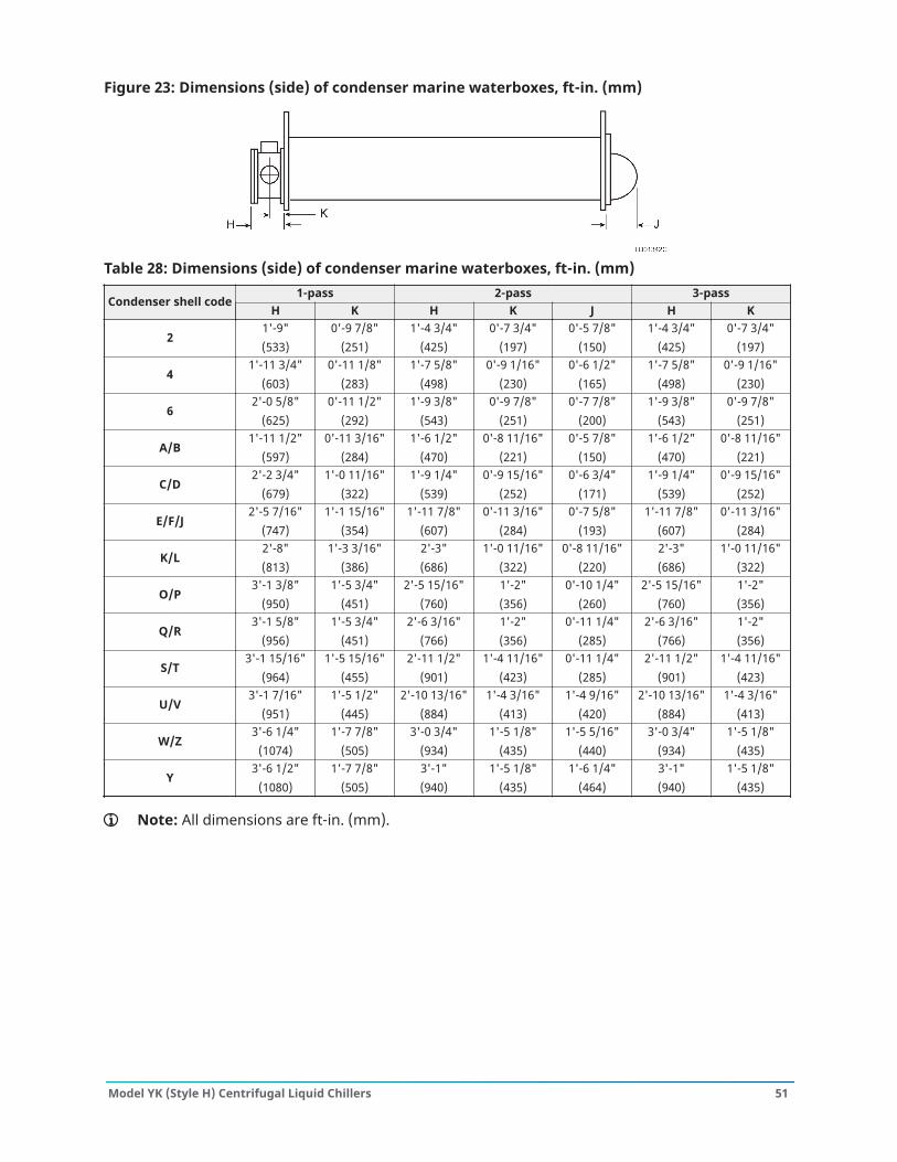
Figure 23: Dimensions (side) of condenser marine waterboxes, ft-in. (mm)
Table 28: Dimensions (side) of condenser marine waterboxes, ft-in. (mm)1-pass 2-pass 3-pass
Condenser shell codeH K H K J H K
21'-9"(533)
0'-9 7/8"(251)
1'-4 3/4"(425)
0'-7 3/4"(197)
0'-5 7/8"(150)
1'-4 3/4"(425)
0'-7 3/4"(197)
41'-11 3/4"
(603)0'-11 1/8"
(283)1'-7 5/8"
(498)0'-9 1/16"
(230)0'-6 1/2"
(165)1'-7 5/8"
(498)0'-9 1/16"
(230)
62'-0 5/8"
(625)0'-11 1/2"
(292)1'-9 3/8"
(543)0'-9 7/8"
(251)0'-7 7/8"
(200)1'-9 3/8"
(543)0'-9 7/8"
(251)
A/B1'-11 1/2"
(597)0'-11 3/16"
(284)1'-6 1/2"
(470)0'-8 11/16"
(221)0'-5 7/8"
(150)1'-6 1/2"
(470)0'-8 11/16"
(221)
C/D2'-2 3/4"
(679)1'-0 11/16"
(322)1'-9 1/4"
(539)0'-9 15/16"
(252)0'-6 3/4"
(171)1'-9 1/4"
(539)0'-9 15/16"
(252)
E/F/J2'-5 7/16"
(747)1'-1 15/16"
(354)1'-11 7/8"
(607)0'-11 3/16"
(284)0'-7 5/8"
(193)1'-11 7/8"
(607)0'-11 3/16"
(284)
K/L2'-8"(813)
1'-3 3/16"(386)
2'-3"(686)
1'-0 11/16"(322)
0'-8 11/16"(220)
2'-3"(686)
1'-0 11/16"(322)
O/P3'-1 3/8"
(950)1'-5 3/4"
(451)2'-5 15/16"
(760)1'-2"(356)
0'-10 1/4"(260)
2'-5 15/16"(760)
1'-2"(356)
Q/R3'-1 5/8"
(956)1'-5 3/4"
(451)2'-6 3/16"
(766)1'-2"(356)
0'-11 1/4"(285)
2'-6 3/16"(766)
1'-2"(356)
S/T3'-1 15/16"
(964)1'-5 15/16"
(455)2'-11 1/2"
(901)1'-4 11/16"
(423)0'-11 1/4"
(285)2'-11 1/2"
(901)1'-4 11/16"
(423)
U/V3'-1 7/16"
(951)1'-5 1/2"
(445)2'-10 13/16"
(884)1'-4 3/16"
(413)1'-4 9/16"
(420)2'-10 13/16"
(884)1'-4 3/16"
(413)
W/Z3'-6 1/4"
(1074)1'-7 7/8"
(505)3'-0 3/4"
(934)1'-5 1/8"
(435)1'-5 5/16"
(440)3'-0 3/4"
(934)1'-5 1/8"
(435)
Y3'-6 1/2"
(1080)1'-7 7/8"
(505)3'-1"(940)
1'-5 1/8"(435)
1'-6 1/4"(464)
3'-1"(940)
1'-5 1/8"(435)
Note: All dimensions are ft-in. (mm).
51Model YK (Style H) Centrifugal Liquid Chillers
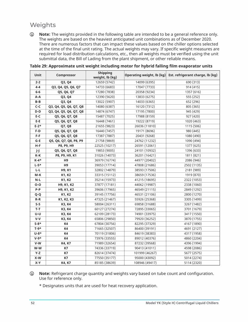
WeightsNote: The weights provided in the following table are intended to be a general reference only.The weights are based on the heaviest anticipated unit combinations as of December 2020.There are numerous factors that can impact these values based on the chiller options selectedat the time of the final unit rating. The actual weights may vary. If specific weight measures arerequired for load distribution calculations, etc., then all weights must be verified using the unitsubmittal data, the Bill of Lading from the plant shipment, or other reliable means.
Table 29: Approximate unit weight including motor for hybrid falling film evaporator units
Unit Compressor Shippingweight, lb (kg) Operating weight, lb (kg) Est. refrigerant charge, lb (kg)
2-2 Q3, Q4 12659 (5742) 14099 (6395) 690 (313)4-4 Q3, Q4, Q5, Q6, Q7 14733 (6683) 17047 (7733) 914 (415)6-6 Q5, Q6, Q7 17280 (7838) 20358 (9234) 1357 (616)A-A Q3, Q4 12390 (5620) 13833 (6275) 555 (252)B-B Q3, Q4 13022 (5907) 14033 (6365) 652 (296)C-C Q3, Q4, Q5, Q6, Q7, Q8 14080 (6387) 16120 (7312) 805 (365)D-D Q3, Q4, Q5, Q6, Q7, Q8 14874 (6747) 17195 (7800) 945 (429)E-C Q5, Q6, Q7, Q8 15487 (7025) 17988 (8159) 927 (420)E-E Q5, Q6, Q7, Q8 16448 (7461) 19222 (8719) 1020 (463)
E-2* Q7, Q8 21655 (9823) 26036 (11810) 1115 (506)F-D Q5, Q6, Q7, Q8 16440 (7457) 19171 (8696) 980 (445)F-F Q5, Q6, Q7, Q8 17387 (7887) 20431 (9268) 1080 (490)G-E Q5, Q6, Q7, Q8, P8, P9 21758 (9869) 24762 (11232) 1090 (494)H-F P8, P9, H9 22525 (10217) 26591 (12061) 1377 (625)J-J Q5, Q6, Q7, Q8 19853 (9005) 24101 (10932) 1396 (633)
K-K P8, P9, H9, K1 31026 (14073) 36201 (16421) 1811 (821)K-4* H9 36979 (16774) 44977 (20402) 2086 (946)L-5* H9 39053 (17714) 47808 (21686) 2502 (1135)L-L H9, K1 32802 (14879) 38593 (17506) 2181 (989)M-K K1, K2 33315 (15112) 38659 (17536) 1919 (870)N-L K1, K2 35214 (15973) 41215 (18695) 2322 (1053)O-O H9, K1, K2 37877 (17181) 44062 (19987) 2338 (1060)P-P H9, K1, K2 39606 (17965) 46549 (21115) 2849 (1292)Q-Q K1, K2 39145 (17756) 46531 (21106) 2800 (1270)R-R K1, K2, K3 47325 (21467) 55926 (25368) 3305 (1499)S-S K3, K4 58004 (26311) 69858 (31688) 3267 (1482)T-T K3, K4 60127 (27274) 72895 (33065) 3701 (1679)U-U K3, K4 62109 (28173) 74901 (33975) 3417 (1550)V-V K3, K4 65806 (29850) 79920 (36252) 3870 (1755)S-8* K4 67804 (30756) 82295 (37329) 4167 (1890)T-9* K4 71665 (32507) 86400 (39191) 4691 (2127)U-8* K4 70119 (31806) 84619 (38383) 4317 (1958)V-9* K4 73976 (33555) 89012 (40376) 4860 (2204)V-W K4, K7 71989 (32654) 87232 (39568) 4396 (1994)W-W K7 74336 (33719) 90413 (41011) 4598 (2086)Y-Z K7 82614 (37474) 101999 (46267) 5677 (2575)X-W K7 77550 (35177) 95000 (43092) 5014 (2274)X-Y K4, K7 85185 (38639) 108946 (49417) 5114 (2320)
Note: Refrigerant charge quantity and weights vary based on tube count and configuration.Use for reference only.
* Designates units that are used for heat recovery application.
Model YK (Style H) Centrifugal Liquid Chillers52
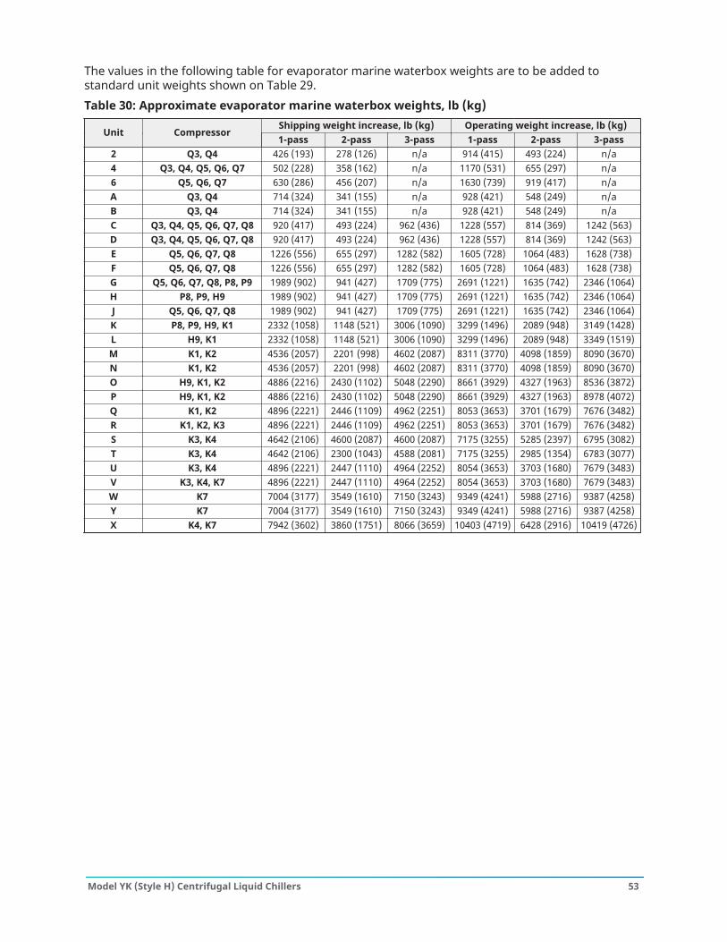
The values in the following table for evaporator marine waterbox weights are to be added tostandard unit weights shown on Table 29.Table 30: Approximate evaporator marine waterbox weights, lb (kg)
Shipping weight increase, lb (kg) Operating weight increase, lb (kg)Unit Compressor
1-pass 2-pass 3-pass 1-pass 2-pass 3-pass2 Q3, Q4 426 (193) 278 (126) n/a 914 (415) 493 (224) n/a4 Q3, Q4, Q5, Q6, Q7 502 (228) 358 (162) n/a 1170 (531) 655 (297) n/a6 Q5, Q6, Q7 630 (286) 456 (207) n/a 1630 (739) 919 (417) n/aA Q3, Q4 714 (324) 341 (155) n/a 928 (421) 548 (249) n/aB Q3, Q4 714 (324) 341 (155) n/a 928 (421) 548 (249) n/aC Q3, Q4, Q5, Q6, Q7, Q8 920 (417) 493 (224) 962 (436) 1228 (557) 814 (369) 1242 (563)D Q3, Q4, Q5, Q6, Q7, Q8 920 (417) 493 (224) 962 (436) 1228 (557) 814 (369) 1242 (563)E Q5, Q6, Q7, Q8 1226 (556) 655 (297) 1282 (582) 1605 (728) 1064 (483) 1628 (738)F Q5, Q6, Q7, Q8 1226 (556) 655 (297) 1282 (582) 1605 (728) 1064 (483) 1628 (738)G Q5, Q6, Q7, Q8, P8, P9 1989 (902) 941 (427) 1709 (775) 2691 (1221) 1635 (742) 2346 (1064)H P8, P9, H9 1989 (902) 941 (427) 1709 (775) 2691 (1221) 1635 (742) 2346 (1064)J Q5, Q6, Q7, Q8 1989 (902) 941 (427) 1709 (775) 2691 (1221) 1635 (742) 2346 (1064)K P8, P9, H9, K1 2332 (1058) 1148 (521) 3006 (1090) 3299 (1496) 2089 (948) 3149 (1428)L H9, K1 2332 (1058) 1148 (521) 3006 (1090) 3299 (1496) 2089 (948) 3349 (1519)M K1, K2 4536 (2057) 2201 (998) 4602 (2087) 8311 (3770) 4098 (1859) 8090 (3670)N K1, K2 4536 (2057) 2201 (998) 4602 (2087) 8311 (3770) 4098 (1859) 8090 (3670)O H9, K1, K2 4886 (2216) 2430 (1102) 5048 (2290) 8661 (3929) 4327 (1963) 8536 (3872)P H9, K1, K2 4886 (2216) 2430 (1102) 5048 (2290) 8661 (3929) 4327 (1963) 8978 (4072)Q K1, K2 4896 (2221) 2446 (1109) 4962 (2251) 8053 (3653) 3701 (1679) 7676 (3482)R K1, K2, K3 4896 (2221) 2446 (1109) 4962 (2251) 8053 (3653) 3701 (1679) 7676 (3482)S K3, K4 4642 (2106) 4600 (2087) 4600 (2087) 7175 (3255) 5285 (2397) 6795 (3082)T K3, K4 4642 (2106) 2300 (1043) 4588 (2081) 7175 (3255) 2985 (1354) 6783 (3077)U K3, K4 4896 (2221) 2447 (1110) 4964 (2252) 8054 (3653) 3703 (1680) 7679 (3483)V K3, K4, K7 4896 (2221) 2447 (1110) 4964 (2252) 8054 (3653) 3703 (1680) 7679 (3483)W K7 7004 (3177) 3549 (1610) 7150 (3243) 9349 (4241) 5988 (2716) 9387 (4258)Y K7 7004 (3177) 3549 (1610) 7150 (3243) 9349 (4241) 5988 (2716) 9387 (4258)X K4, K7 7942 (3602) 3860 (1751) 8066 (3659) 10403 (4719) 6428 (2916) 10419 (4726)
53Model YK (Style H) Centrifugal Liquid Chillers
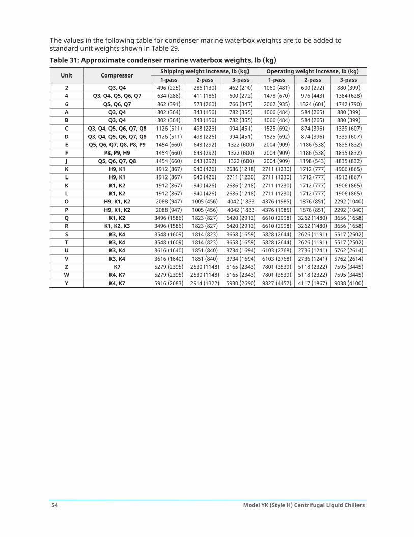
The values in the following table for condenser marine waterbox weights are to be added tostandard unit weights shown in Table 29.Table 31: Approximate condenser marine waterbox weights, lb (kg)
Shipping weight increase, lb (kg) Operating weight increase, lb (kg)Unit Compressor
1-pass 2-pass 3-pass 1-pass 2-pass 3-pass2 Q3, Q4 496 (225) 286 (130) 462 (210) 1060 (481) 600 (272) 880 (399)4 Q3, Q4, Q5, Q6, Q7 634 (288) 411 (186) 600 (272) 1478 (670) 976 (443) 1384 (628)6 Q5, Q6, Q7 862 (391) 573 (260) 766 (347) 2062 (935) 1324 (601) 1742 (790)A Q3, Q4 802 (364) 343 (156) 782 (355) 1066 (484) 584 (265) 880 (399)B Q3, Q4 802 (364) 343 (156) 782 (355) 1066 (484) 584 (265) 880 (399)C Q3, Q4, Q5, Q6, Q7, Q8 1126 (511) 498 (226) 994 (451) 1525 (692) 874 (396) 1339 (607)D Q3, Q4, Q5, Q6, Q7, Q8 1126 (511) 498 (226) 994 (451) 1525 (692) 874 (396) 1339 (607)E Q5, Q6, Q7, Q8, P8, P9 1454 (660) 643 (292) 1322 (600) 2004 (909) 1186 (538) 1835 (832)F P8, P9, H9 1454 (660) 643 (292) 1322 (600) 2004 (909) 1186 (538) 1835 (832)J Q5, Q6, Q7, Q8 1454 (660) 643 (292) 1322 (600) 2004 (909) 1198 (543) 1835 (832)K H9, K1 1912 (867) 940 (426) 2686 (1218) 2711 (1230) 1712 (777) 1906 (865)L H9, K1 1912 (867) 940 (426) 2711 (1230) 2711 (1230) 1712 (777) 1912 (867)K K1, K2 1912 (867) 940 (426) 2686 (1218) 2711 (1230) 1712 (777) 1906 (865)L K1, K2 1912 (867) 940 (426) 2686 (1218) 2711 (1230) 1712 (777) 1906 (865)O H9, K1, K2 2088 (947) 1005 (456) 4042 (1833 4376 (1985) 1876 (851) 2292 (1040)P H9, K1, K2 2088 (947) 1005 (456) 4042 (1833 4376 (1985) 1876 (851) 2292 (1040)Q K1, K2 3496 (1586) 1823 (827) 6420 (2912) 6610 (2998) 3262 (1480) 3656 (1658)R K1, K2, K3 3496 (1586) 1823 (827) 6420 (2912) 6610 (2998) 3262 (1480) 3656 (1658)S K3, K4 3548 (1609) 1814 (823) 3658 (1659) 5828 (2644) 2626 (1191) 5517 (2502)T K3, K4 3548 (1609) 1814 (823) 3658 (1659) 5828 (2644) 2626 (1191) 5517 (2502)U K3, K4 3616 (1640) 1851 (840) 3734 (1694) 6103 (2768) 2736 (1241) 5762 (2614)V K3, K4 3616 (1640) 1851 (840) 3734 (1694) 6103 (2768) 2736 (1241) 5762 (2614)Z K7 5279 (2395) 2530 (1148) 5165 (2343) 7801 (3539) 5118 (2322) 7595 (3445)W K4, K7 5279 (2395) 2530 (1148) 5165 (2343) 7801 (3539) 5118 (2322) 7595 (3445)Y K4, K7 5916 (2683) 2914 (1322) 5930 (2690) 9827 (4457) 4117 (1867) 9038 (4100)
Model YK (Style H) Centrifugal Liquid Chillers54
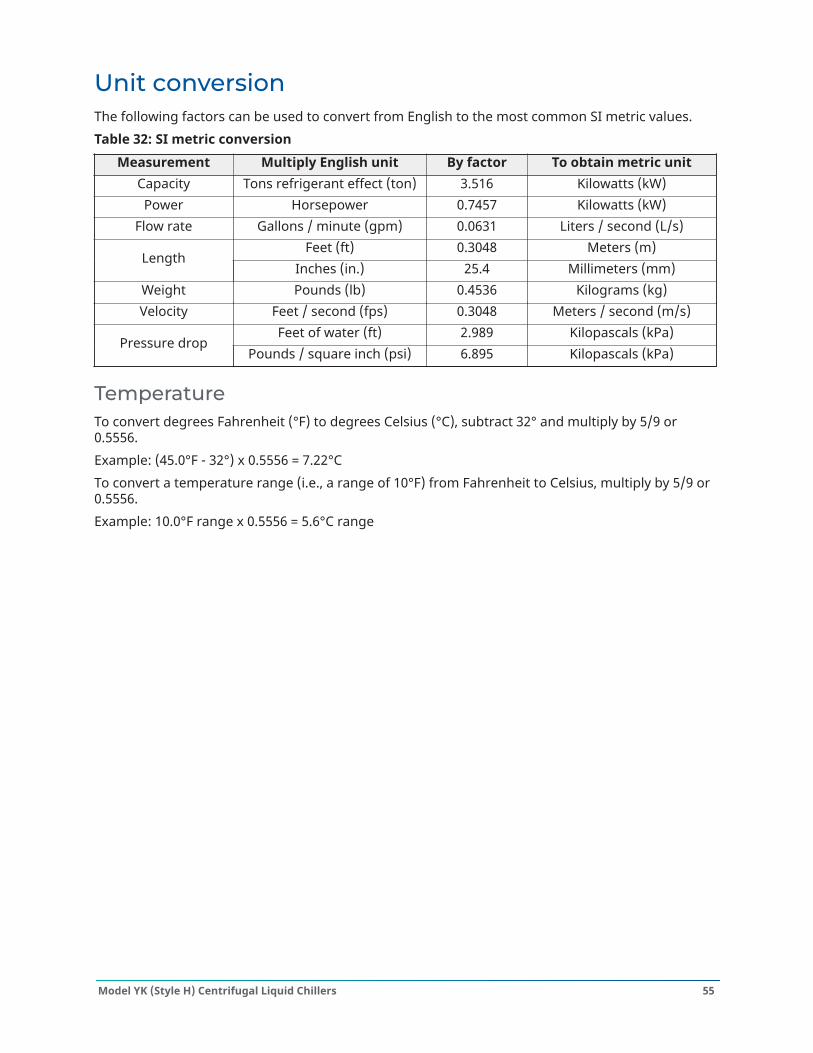
Unit conversionThe following factors can be used to convert from English to the most common SI metric values.Table 32: SI metric conversion
Measurement Multiply English unit By factor To obtain metric unitCapacity Tons refrigerant effect (ton) 3.516 Kilowatts (kW)Power Horsepower 0.7457 Kilowatts (kW)
Flow rate Gallons / minute (gpm) 0.0631 Liters / second (L/s)Feet (ft) 0.3048 Meters (m)
LengthInches (in.) 25.4 Millimeters (mm)
Weight Pounds (lb) 0.4536 Kilograms (kg)Velocity Feet / second (fps) 0.3048 Meters / second (m/s)
Feet of water (ft) 2.989 Kilopascals (kPa)Pressure drop
Pounds / square inch (psi) 6.895 Kilopascals (kPa)
TemperatureTo convert degrees Fahrenheit (°F) to degrees Celsius (°C), subtract 32° and multiply by 5/9 or0.5556.Example: (45.0°F - 32°) x 0.5556 = 7.22°CTo convert a temperature range (i.e., a range of 10°F) from Fahrenheit to Celsius, multiply by 5/9 or0.5556.Example: 10.0°F range x 0.5556 = 5.6°C range
55Model YK (Style H) Centrifugal Liquid Chillers

© 2021 Johnson Controls. 5000 Renaissance Drive, New Freedom, York, PA 17349, USA. Subject to change without notice. Allrights reserved.