model 610-02 - cla-val
TRANSCRIPT
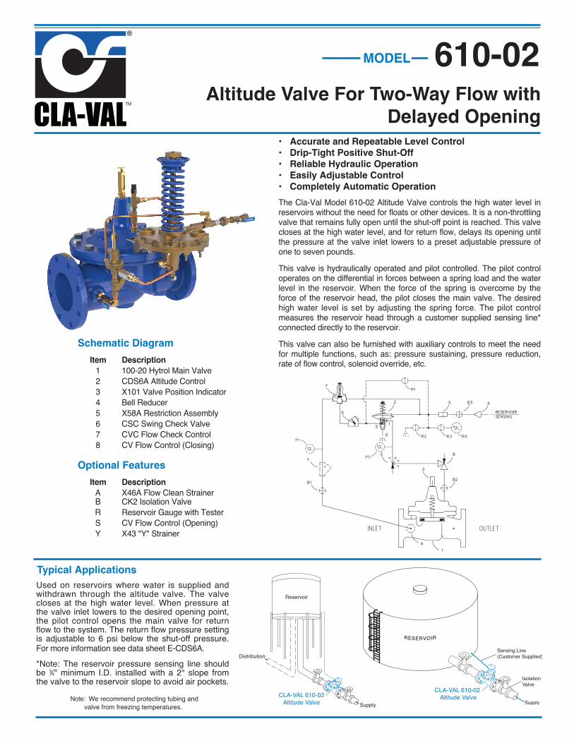
• Accurate and Repeatable Level Control• Drip-Tight Positive Shut-Off• Reliable Hydraulic Operation• Easily Adjustable Control• Completely Automatic OperationThe Cla-Val Model 610-02 Altitude Valve controls the high water level inreservoirs without the need for floats or other devices. It is a non-throttlingvalve that remains fully open until the shut-off point is reached. This valvecloses at the high water level, and for return flow, delays its opening untilthe pressure at the valve inlet lowers to a preset adjustable pressure ofone to seven pounds.This valve is hydraulically operated and pilot controlled. The pilot controloperates on the differential in forces between a spring load and the waterlevel in the reservoir. When the force of the spring is overcome by theforce of the reservoir head, the pilot closes the main valve. The desiredhigh water level is set by adjusting the spring force. The pilot controlmeasures the reservoir head through a customer supplied sensing line*connected directly to the reservoir.This valve can also be furnished with auxiliary controls to meet the needfor multiple functions, such as: pressure sustaining, pressure reduction,rate of flow control, solenoid override, etc.
Schematic Diagram Item Description 1 100-20 Hytrol Main Valve 2 CDS6A Altitude Control 3 X101 Valve Position Indicator 4 Bell Reducer 5 X58A Restriction Assembly 6 CSC Swing Check Valve 7 CVC Flow Check Control 8 CV Flow Control (Closing)
Optional Features Item Description A X46A Flow Clean Strainer B CK2 Isolation Valve R Reservoir Gauge with Tester S CV Flow Control (Opening) Y X43 "Y" Strainer
Typical ApplicationsUsed on reservoirs where water is supplied andwithdrawn through the altitude valve. The valvecloses at the high water level. When pressure atthe valve inlet lowers to the desired opening point,the pilot control opens the main valve for returnflow to the system. The return flow pressure settingis adjustable to 6 psi below the shut-off pressure.For more information see data sheet E-CDS6A.*Note: The reservoir pressure sensing line shouldbe 3⁄4" minimum I.D. installed with a 2° slope fromthe valve to the reservoir slope to avoid air pockets.
Altitude Valve For Two-Way Flow withDelayed Opening
Note: We recommend protecting tubing andvalve from freezing temperatures.
MODEL 610-02
CLA-VAL 610-02Altitude Valve
CLA-VAL 610-02 Altitude Valve

Model 610-02 (Uses Basic Valve Model 100-20)
Model 610-02 Dimensions (In Inches)Valve Size (Inches) 3 4 6 8 10 12 14 16 18 20 24 30 36 48A 150 ANSI 10.25 13.88 17.75 21.38 26.00 30.00 34.25 35.00 42.12 48.00 48.00 63.25 65.00 88.0AA 300 ANSI 11.00 14.50 18.62 22.38 27.38 31.50 35.75 36.62 43.63 49.62 49.75 63.75 67.00 90.62B Diameter 6.62 9.12 11.50 15.75 20.00 23.62 27.47 28.00 35.44 35.44 35.44 53.19 56.00 66.00C Maximum 7.00 8.62 11.62 15.00 17.88 21.00 20.88 25.75 25.00 31.50 31.50 43.94 54.75 59.00D 150 ANSI — 6.94 8.88 10.69 12.75 14.94 — — 20.93 21.06 — — — —DD 300 ANSI — 7.25 9.38 11.19 — — — — — — — — — —E 150 ANSI — 5.50 6.75 7.25 8.06 8.68 — — 15.81 15.94 — — — —EE 300 ANSI — 5.81 7.25 7.75 — — — — — — — — — —F 150 ANSI 3.75 4.50 5.50 6.75 8.00 9.50 11.00 11.75 15.88 14.56 17.00 19.88 25.50 34.00FF 300 ANSI 4.12 5.00 6.25 7.50 8.75 10.25 11.50 12.75 15.88 16.06 19.00 22.00 27.50 38.50H NPT Body Tapping 0.375 0.50 0.75 0.75 1.00 1.00 1.00 1.00 1.00 1.00 1.00 1.00 2.00 2.00J NPT Cover Center Plug 0.50 0.50 0.75 0.75 1.00 1.00 1.25 1.25 2.00 2.00 2.00 1.00 2.00 2.00K NPT Cover Tapping 0.375 0.50 0.75 0.75 1.00 1.00 1.00 1.00 1.00 1.00 1.00 1.00 2.00 2.00Stem Travel 0.60 0.80 1.10 1.70 2.30 2.80 3.40 4.50 4.50 4.50 6.50 7.50 7.50 8.50Approx. Ship Weight (lbs) 45 85 195 330 625 900 1250 1380 2365 2551 2733 6500 8545 13100Approx. X Pilot System 13 15 27 30 33 36 36 41 40 46 55 68 79 86Approx. Y Pilot System 10 11 18 20 22 24 26 26 30 30 30 39 40 47Approx. Z Pilot System 10 11 18 20 22 24 26 26 30 30 30 39 42 49
Valve Body & CoverPressure Class
Flanged
Grade Material ANSIStandards*
150Class
300Class
ASTM A536 Ductile Iron B16.42 250 400
ASTM A216-WCB Cast Steel B16.5 285 400
UNS 87850 Bronze B16.24 225 400
Note: * ANSI standards are for flange dimensions only. Flanged valves are available faced but not drilled. ‡ End Details machined to ANSI B2.1 specifications.
Valves for higher pressure are available; consult factory for details
Pressure Ratings (Recommended Maximum Pressure - psi)
Cover CapacityLiquid VolumeDisplaced from
Diaphragm ChamberWhen Valve
Opens or ClosesValveSize
Displace-ment
3” .032 gal4” .080 gal6” .169 gal8” .531 gal10” 1.26 gal12” 2.51 gal14” 2.51 gal16” 4.00 gal18” 4.00 gal20” 9.57 gal24” 9.57 gal30” 29.00 gal
Component Standard Material CombinationsBody & Cover Ductile Iron Cast Steel Bronze
Available Sizes 3" - 48"80 - 1200 mm
3" - 16"80 - 400 mm
3" - 16"80 - 400 mm
Disc Retainer &Diaphragm Washer Cast Iron Cast Steel BronzeTrim: Disc Guide, Seat & Cover Bearing
Bronze is StandardStainless Steel is Optional
Disc Buna-N® RubberDiaphragm Nylon Reinforced Buna-N® RubberStem, Nut & Spring Stainless SteelFor material options not listed, consult factory.Cla-Val manufactures valves in more than 50 different alloys.
Materials
EE
D
E
InletDD
AA
X
100-20Flanged
F
A
C(MAX)
K
J
H
InletOutlet
FF
B (Diameter)
Y
Z
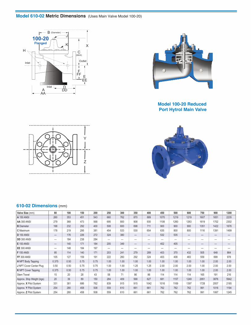
610-02 Dimensions (mm)Valve Size (mm) 80 100 150 200 250 300 350 400 450 500 600 750 900 1200A 150 ANSI 260 353 451 543 660 762 870 889 1070 1219 1219 1607 1651 2235AA 300 ANSI 279 368 473 568 695 800 908 930 1108 1260 1263 1619 1702 2302B Diameter 168 232 292 400 508 600 698 711 900 900 900 1351 1422 1676C Maximum 178 219 295 381 454 533 530 654 635 800 800 1116 1391 1499D 150 ANSI — 176 226 272 324 380 — — 532 535 — — — —DD 300 ANSI — 184 238 284 — — — — — — — — — —E 150 ANSI — 140 171 184 205 349 — — 402 405 — — — —EE 300 ANSI — 148 184 197 — — — — — — — — — —F 150 ANSI 95 114 140 171 203 241 279 289 403 370 432 505 648 864FF 300 ANSI 105 127 159 191 222 260 292 324 403 408 483 559 699 978H NPT Body Tapping 0.375 0.50 0.75 0.75 1.00 1.00 1.00 1.00 1.00 1.00 1.00 1.00 2.00 2.00J NPT Cover Center Plug 0.50 0.50 0.75 0.75 1.00 1.00 1.25 1.25 2.00 2.00 2.00 1.00 2.00 2.00K NPT Cover Tapping 0.375 0.50 0.75 0.75 1.00 1.00 1.00 1.00 1.00 1.00 1.00 1.00 2.00 2.00Stem Travel 15 20 28 43 58 71 86 86 114 114 114 165 191 216Approx. Ship Weight (kgs) 20 39 89 150 284 409 568 627 681 1157 1249 2951 3876 5942Approx. X Pilot System 331 381 686 762 839 915 915 1042 1016 1169 1397 1728 2007 2185Approx. Y Pilot System 254 280 458 508 559 610 661 661 762 762 762 991 1016 1194Approx. Z Pilot System 254 280 458 508 559 610 661 661 762 762 762 991 1067 1245
Model 610-02 Metric Dimensions (Uses Main Valve Model 100-20)
Y
Z
EE
D
E
InletDD
AA
X
100-20Flanged
F
A
C(MAX)
K
J
H
InletOutlet
FF
B (Diameter)
Model 100-20 ReducedPort Hytrol Main Valve
Adjustment Ranges 5 - 40 ft. 30 - 80 ft. 70 - 120 ft. 110 - 160 ft. 150 - 200 ft. Temperature Range
Water: to 180°FIf flowing line pressure is less than 10 psi, consult factory for full details.If inlet pressure is above 150 psi, consultfactory for recommendations.Materials Standard Pilot System Materials Pilot Control: Low Lead Bronze Trim: Stainless Steel Type 303 Rubber: Buna-N® Synthetic Rubber Optional Pilot System Materials Pilot Systems are available with optional Aluminum, Stainless Steel, or Monel materials. Valve position indicator is
standard
Pilot System Specifications
E-610-02 (R-03/2021)
CLA-VAL EUROPEChemin des Mésanges 1CH-1032 Romanel/Lausanne, SwitzerlandPhone: 41-21-643-15-55www.cla-val.chE-mail: [email protected]
CLA-VAL FRANCEPorte du Grand Lyon 1ZAC du Champ du PérierFrance - 01700 NeyronPhone: 33-4-72-25-92-93www.cla-val.chE-mail: [email protected]
CLA-VAL1701 Placentia Avenue • Costa Mesa, CA 92627
800-942-6326 • Web Site: www.cla-val.com • E-mail: [email protected]
© COPYRIGHT CLA-VAL 2021 Printed in USA Specifications subject to change without notice. visit www.cla-val-latinamerica.com for Spanish literature
CLA-VAL CANADA4687 Christie DriveBeamsville, OntarioCanada L0R 1B4Phone: 905-563-4963www.cla-val.comE-mail [email protected]
CLA-VAL UKDainton House, Goods Station RoadTunbridge Wells Kent TN1 2 DH EnglandPhone: 44-1892-514-400www.cla-val.chE-mail: [email protected]
CLA-VAL ASIA PACIFIC45 Kennaway RoadWoolston, Christchurch, 8023New ZealandPhone: 64-39644860www.cla-valpacific.comE-mail: [email protected]
1. Catalog No. 610-02 2. Valve Size 3. Pattern - Globe or Angle 4. Pressure Class 5. Threaded or Flanged 6. Materials Desired
7. Adjustment Range 8. Desired Options 9. When Vertically Installed10. When “D” feature is ordered,
the “H” feature is required.
When Ordering Please SpecifyFor a comprehensive overview of Cla-Val
Altitude Control Valves, please vist www.cla-val.com and use.
keyword search “Altitude”.
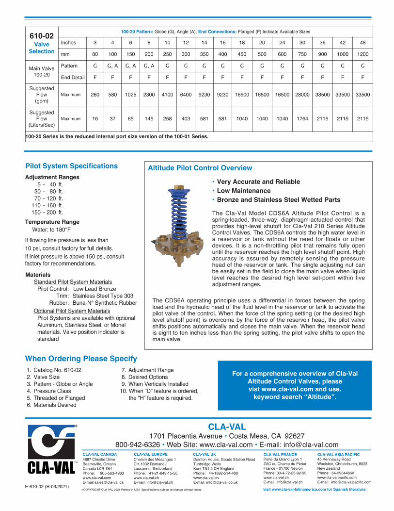
• Very Accurate and Reliable • Low Maintenance • Bronze and Stainless Steel Wetted PartsThe Cla-Val Model CDS6A Altitude Pilot Control is aspring-loaded, three-way, diaphragm-actuated control thatprovides high-level shutoff for Cla-Val 210 Series AltitudeControl Valves. The CDS6A controls the high water level ina reservoir or tank without the need for floats or otherdevices. It is a non-throttling pilot that remains fully openuntil the reservoir reaches the high level shutoff point. Highaccuracy is assured by remotely sensing the pressurehead of the reservoir or tank. The single adjusting nut canbe easily set in the field to close the main valve when liquidlevel reaches the desired high level set-point within fiveadjustment ranges.
Altitude Pilot Control Overview
The CDS6A operating principle uses a differential in forces between the springload and the hydraulic head of the fluid level in the reservoir or tank to activate thepilot valve of the control. When the force of the spring setting (or the desired highlevel shutoff point) is overcome by the force of the reservoir head, the pilot valveshifts positions automatically and closes the main valve. When the reservoir headis eight to ten inches less than the spring setting, the pilot valve shifts to open themain valve.
610-02Valve
Selection
100-20 Pattern: Globe (G), Angle (A), End Connections: Flanged (F) Indicate Available Sizes
Inches 3 4 6 8 10 12 14 16 18 20 24 30 36 42 48
mm 80 100 150 200 250 300 350 400 450 500 600 750 900 1000 1200
Main Valve100-20
Pattern G G, A G, A G, A G G G G G G G G G G GEnd Detail F F F F F F F F F F F F F F F
Suggested Flow (gpm)
Maximum 260 580 1025 2300 4100 6400 9230 9230 16500 16500 16500 28000 33500 33500 33500
Suggested Flow
(Liters/Sec)Maximum 16 37 65 145 258 403 581 581 1040 1040 1040 1764 2115 2115 2115
100-20 Series is the reduced internal port size version of the 100-01 Series.