92-01/692-01 - cla-val
TRANSCRIPT

92-01/692-01

11
-3
0-7
8
11
-3
0-7
8
11
-3
0-7
8
DP
CH
WA
L
SE
E R
EV
IS
IO
N F
ILE
A-G
CA
D R
EV
IS
IO
N R
EC
OR
D
DA
TE
BY
DE
SC
RIP
TIO
NLT
R
Model 92-01/692-01
76561 J
► CLA-VAL Companywww.cla-val.com SHEET OF 3
®
TM
Combination Pressure Reducing and Pressure Sustaining Valve
1
AD
DE
D C
RL60 T
O C
OM
PO
NE
NT
LIS
T (E
CO
23596)
HR
P12-11-13
RE
DR
AW
N IN
N
EW
S
CH
EM
AT
IC
F
OR
MA
T (E
CO
26780)
JA
V6-5-18
NO. BASIC COMPONENTS QTY
1
100-01 HYTROL (92-01) MAIN VALVE/100-20 HYTROL (692-01) MAIN VALVE
1
2 X44A STRAINER & ORIFICE ASSEMBLY 1
3 CRD PRESSURE REDUCING CONTROL 1
4 CRL/CRL60 PRESSURE RELIEF CONTROL 1
5
CV FLOW CONTROL (OPENING)
1
NO. OPTIONAL FEATURES QTY
B
CK2 COCK (ISOLATION VALVE)
3
C
CV FLOW CONTROL (CLOSING)
1
D CHECK VALVES WITH COCK 1
F REMOTE PILOT SENSING
P X141 PRESSURE GAUGE ASSEMBLY 3
V X101 VALVE POSITION INDICATOR 1
1
OUTLETINLET
5
V
P2
B
P3
B
D2
B
4
REMOTE
SENSING
F
2
D3
3
P1
D1
C

► OPERATING DATA
Model 92-01/692-01
76561 J
► CLA-VAL Companywww.cla-val.com SHEET OF 3
®
TM
Combination Pressure Reducing and Pressure Sustaining Valve
2
Pressure Reducing Feature
Pressure reducing control (3) is a normally open control that senses main valve outlet pressure changes. An increase in outletpressure tends to close control (3) and a decrease in outlet pressure tends to open control (3). This causes main valve coverpressure to vary and the main valve modulates (opens and closes) maintaining a relatively constant outlet pressure. Pressurereducing control (3) adjustment: Turn the adjusting screw clockwise to increase the setting.
Pressure Sustaining Feature
Pressure relief control (4) is a normally closed control that senses main valve inlet pressure changes. Control (4) is open ifinlet pressure is higher than the set point of control (4). This places pressure reducing control (3) in command of the mainvalve. If inlet pressure lowers to the set point of control (4), control (4) closes. This pressurizes the main valve cover andthe main valve closes, sustaining the desired minimum pressure at the main valve inlet. Pressure relief control (4)adjustment: Turn the adjusting screw clockwise to increase the setting.
Opening Speed Control
Flow Control (5) controls the opening speed of the main valve. Turn the adjusting stem clockwise to make the main valveopen slower.
Optional Features
(B) - Isolation Valves:
Isolation Valves (B) are used to isolate the pilot system from main line pressure. These valves must be open during normal
operation.
(C) - Closing Speed Control:
Flow control (C) controls the closing speed of the main valve. Turn the adjusting stem clockwise to make the main valve close
slower.
(D) - Check Valves with Isolation Valves:
When outlet pressure is higher than inlet pressure, check valve (D2) opens and check valve (D1) closes. This directs the higher
outlet pressure into the main valve cover and the main valve closes.
(F) - Remote Pilot Sensing:
Pilot sensing pressure is obtained from a point upstream of the main valve inlet. (Pilot sensing pressure is obtained from the main
valve inlet if suffix (F) is not specified.)
(P) - Pressure Gauge:
Pressure gauges (P1), (P2), and (P3) provide pressure reading in the inlet, outlet, and cover connections.
(V) - Valve Position Indicator:
Valve position indicator (V) displays a visual position of the main valve stem.

Model 92-01/692-01
76561 J
► CLA-VAL Companywww.cla-val.com SHEET OF 3
®
TM
Combination Pressure Reducing and Pressure Sustaining Valve
3
► OPERATING DATA - CONTINUED
► CHECK LIST FOR PROPER OPERATION
□ System valves open upstream and downstream.
□ Air removed from the main valve cover and pilot system at all high points.
□ Periodical cleaning of strainer (2) is recommended.
□ Remote sensing line properly connected (optional feature).
□ Flow control (5) open at least 4 turns.
□ Flow control (C) open at least 4 turns (optional feature).
□ Isolation valves (B) and (D3) open (optional feature).

Recommended Inspections
Cla-Val recommends that an inspection be performed on our products annually. The inspection should include both a visual and functional test of the main valve/component and the pilot system. The inspection ensures that no damage or premature wear occurred due to velocity, pressure, or foreign matter within the fluid that may have exceeded the valve’s design. Please consult the maintenance manual for specific information on the model. Manuals are available for download at Cla-Val.com, as well as contact information for a company representative.
Accurate record-keeping is a best practice for any preventative maintenance program, and Cla-Val strongly recommends this action through an asset management program. Cla-Val provides a free asset management tool, Link2Valves Link2Valves - Cla-Val (cla-val.com), to assist in preventative maintenance record-keeping and scheduling.
CLA-VAL 1701 Placentia Ave • Costa Mesa CA 92627 • Phone: 949-722-4800 • Fax: 949-548-5441 • E-mail: [email protected] • www.cla-val.com Copyright Cla-Val 2021 • Printed in USA • Specifications subject to change without notice.©
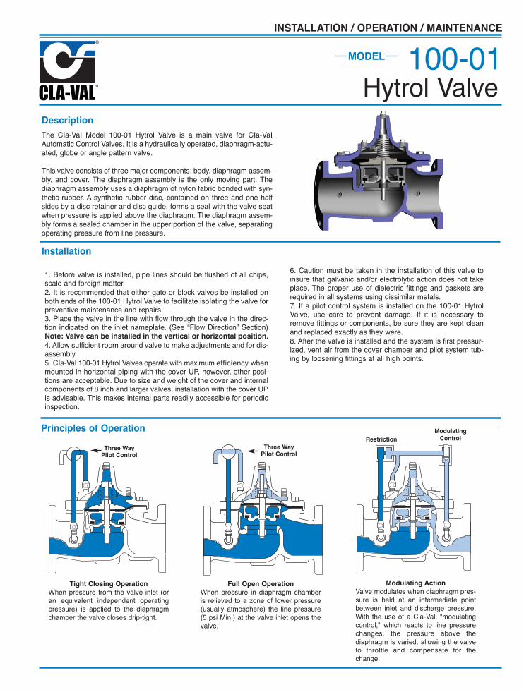
Description
The CIa-VaI Model 100-01 Hytrol Valve is a main valve for CIa-VaIAutomatic Control Valves. It is a hydraulically operated, diaphragm-actu-ated, globe or angle pattern valve.
This valve consists of three major components; body, diaphragm assem-bly, and cover. The diaphragm assembly is the only moving part. Thediaphragm assembly uses a diaphragm of nylon fabric bonded with syn-thetic rubber. A synthetic rubber disc, contained on three and one halfsides by a disc retainer and disc guide, forms a seal with the valve seatwhen pressure is applied above the diaphragm. The diaphragm assem-bly forms a sealed chamber in the upper portion of the valve, separatingoperating pressure from line pressure.
Installation
1. Before valve is installed, pipe lines should be flushed of all chips,scale and foreign matter.2. It is recommended that either gate or block valves be installed onboth ends of the 100-01 Hytrol Valve to facilitate isoIating the valve forpreventive maintenance and repairs.3. Place the valve in the line with flow through the valve in the direc-tion indicated on the inlet nameplate. (See “Flow Direction” Section)Note: Valve can be installed in the vertical or horizontal position.
4. Allow sufficient room around valve to make adjustments and for dis-assembly.5. CIa-VaI 100-01 Hytrol Valves operate with maximum efficiency whenmounted in horizontal piping with the cover UP, however, other posi-tions are acceptable. Due to size and weight of the cover and internalcomponents of 8 inch and larger valves, installation with the cover UPis advisable. This makes internal parts readily accessible for periodicinspection.
6. Caution must be taken in the installation of this valve toinsure that galvanic and/or electrolytic action does not takeplace. The proper use of dielectric fittings and gaskets arerequired in all systems using dissimilar metals.7. If a pilot control system is installed on the 100-01 HytrolValve, use care to prevent damage. If it is necessary toremove fittings or components, be sure they are kept cleanand replaced exactly as they were.8. After the valve is installed and the system is first pressur-ized, vent air from the cover chamber and pilot system tub-ing by loosening fittings at all high points.
Tight Closing Operation
When pressure from the valve inlet (oran equivalent independent operatingpressure) is applied to the diaphragmchamber the valve closes drip-tight.
Full Open Operation
When pressure in diaphragm chamberis relieved to a zone of lower pressure(usually atmosphere) the line pressure(5 psi Min.) at the valve inlet opens thevalve.
Modulating Action
Valve modulates when diaphragm pres-sure is held at an intermediate pointbetween inlet and discharge pressure.With the use of a Cla-Val. "modulatingcontrol," which reacts to line pressurechanges, the pressure above thediaphragm is varied, allowing the valveto throttle and compensate for thechange.
Principles of Operation
Three Way Pilot Control
Three Way Pilot Control
Restriction
Modulating
Control
100-01Hytrol Valve
MODEL
INSTALLATION / OPERATION / MAINTENANCE

2
Flow Direction
The flow through the 100-01 Hytrol Valve can be in one of twodirections. When flow is “up-and-over the seat,” it is in “normal”flow and the valve will fail in the open position. When flow is “over-the seat-and down,” it is in “reverse” flow and the valve will fail inthe closed position. There are no permanent flow arrow markings.The valve must be installed according to nameplate data.
BRIDGEWALL INDlCATOR
Normal Flow Reverse Flow
Troubleshooting
The following troubleshooting information deals strictly with theModel 100-01 Hytrol Valve. This assumes that all other compo-nents of the pilot control system have been checked out and arein proper working condition. (See appropriate sections inTechnical Manual for complete valve).
Three Checks
The 100-01 Hytrol Valve has only one moving part (the diaphragmand disc assembly). So, there are only three major types of prob-lems to be considered.
First: Valve is stuck - that is, the diaphragm assembly is not freeto move through a full stroke either from open to close or viceversa.
Second: Valve is free to move and can’t close because of a wornout diaphragm.
Third: Valve leaks even though it is free to move and thediaphragm isn’t leaking.
Closed isolation valves in control system, or in main line.
Lack of cover chamber pressure.
Diaphragm damaged. (See Diaphragm Check.)
Diaphragm assembly inoperative.Corrosion or excessive scale build up on valve stem.(See Freedom of Movement Check)
Mechanical obstruction. Object lodged in valve.(See Freedom of Movement Check)
Worn disc. (See Tight Sealing Check)
Badly scored seat. (See Tight Sealing Check)
Closed upstream and/or downstream isolation valves in main line.
Insufficient line pressure.
Diaphragm assembly inoperative. Corrosion or excessivebuildup on valve stem. (See Freedom of Movement Check)
Diaphragm damaged. (For valves in "reverse flow" only)
After checking out probable causes and remedies, the following three checks can be used to diagnose the nature of the
problem before maintenance is started. They must be done in the order shown.
Open Isolation valves.
Check upstream pressure, pilot system, strainer, tubing, valves, or needlevalves for obstruction.
Replace diaphragm.
Clean and polish stem. Inspect and replace any damaged or badly erodedpart.
Remove obstruction.
Replace disc.
Replace seat.
Open isolation valves.
Check upstream pressure. (Minimum 5 psi flowing line pressure differential.)
Clean and polish stem. Inspect and replace anydamaged or badly eroded part.
Replace diaphragm.
Fails to Close
Fails to Open
CAUTION: Care should be taken when doing the troubleshooting checks onthe 100-01 Hytrol Valve. These checks do require the valve toopen fully. This will either allow a high flow rate through thevalve, or the downstream pressure will quickly increase to theinlet pressure. In some cases, this can be very harmful. Wherethis is the case, and there are no block valves in the system toprotect the downstream piping, it should be realized that thevalve cannot be serviced under pressure. Steps should betaken to remedy this situation before proceeding any further.
(cast into side of valve body)
SYMPTOM PROBABLE CAUSE REMEDY
Recommended Tools1. Three pressure gauges with ranges suitable to the instal-lation to be put at Hytrol inlet, outlet and cover connections.
2. Cla-Val Model X101 Valve Position Indicator. This pro-vides visual indication of valve position without disassemblyof valve.
3. Other items are: suitable hand tools such as screw-drivers, wrenches, etc. soft jawed (brass or aluminum) vise,400 grit wet or dry sandpaper and water for cleaning.
All trouble shooting is possible without removing the valve from theline or removing the cover. It is highly recommended to permanentlyinstall a Model X101 Valve Position Indicator and three gauges inunused Hytrol inlet, outlet and cover connections.

Diaphragm Check (#1 )
1. Shut off pressure to the Hytrol Valve by slowly closing upstreamand downstream isolation valves. SEE CAUTION.2. Disconnect or close all pilot control lines to the valve cover andleave only one fitting in highest point of cover open to atmosphere.3.With the cover vented to atmosphere, slowly open upstreamisolation valve to allow some pressure into the Hytrol Valve body.Observe the open cover tapping for signs of continuous flow. It isnot necessary to fully open isolating valve. Volume in cover cham-ber capacity chart will be displaced as valve moves to open posi-tion. Allow sufficient time for diaphragm assembly to shift posi-tions. If there is no continuous flow, you can be quite certain thediaphragm is sound and the diaphragm assembly is tight. If thefluid appears to flow continuously this is a good reason to believethe diaphragm is either damaged or it is loose on the stem. Ineither case, this is sufficient cause to remove the valve cover andinvestigate the leakage. (See “Maintenance” Section for procedure.)
Freedom of Movement Check (#2)
4. Determining the Hytrol Valve’s freedom of movement can bedone by one of two methods.5. For most valves it can be done after completing DiaphragmCheck (Steps 1, 2, and 3). SEE CAUTION. At the end of step 3the valve should be fully open.6. If the valve has a Cla-Val X101 Position Indicator, observe theindicator to see that the valve opens wide. Mark the point of max-imum opening.7. Re-connect enough of the control system to permit the appli-cation of inlet pressure to the cover. Open pilot system cock sopressure flows from the inlet into the cover.8. While pressure is building up in the cover, the valve shouldclose smoothly. There is a hesitation in every Hytrol Valve closure,which can be mistaken for a mechanical bind. The stem willappear to stop moving very briefly before going to the closed posi-tion. This slight pause is caused by the diaphragm flexing at aparticular point in the valve’s travel and is not caused by amechanical bind.9. When closed, a mark should be made on the X101 Valve posi-tion indicator corresponding to the “closed” position. The distancebetween the two marks should be approximately the stem travelshown in chart.
10. If the stroke is different than that shown in stem travel chartthis is a good reason to believe something is mechanically restrict-ing the stroke of the valve at one end of its travel. If the flow doesnot stop through the valve when in the indicated “closed” position,the obstruction probably is between the disc and the seat. If theflow does stop, then the obstruction is more likely in the cover. Ineither case, the cover must be removed, and the obstruction locat-ed and removed. The stem should also be checked for scale build-up. (See “Maintenance, section for procedure.)11. For valves 6” and smaller, the Hytrol Valve’s freedom of move-ment check can also be done after all pressure is removed fromthe valve. SEE CAUTION. After closing inlet and outlet isolationvalves and bleeding pressure from the valve, check that the coverchamber and the body are temporarily vented to atmosphere.Insert fabricated tool into threaded hole in top of valve stem, andlift the diaphragm assembly manually. Note any roughness. Thediaphragm assembly should move smoothly throughout entirevalve stroke. The tool is fabricated from rod that is threaded onone end to fit valve stem and has a “T” bar handle of some kindon the other end for easy gripping. (See chart in Step 4 of“Disassembly” Section.)12. Place marks on this diaphragm assembly lifting tool when thevalve is closed and when manually positioned open. The distancebetween the two marks should be approximately the stem travelshown in stem travel chart. If the stroke is different than thatshown, there is a good reason to believe something is mechani-cally restricting the stroke of the valve. The cover must beremoved, and the obstruction located and removed. The stemshould also be checked for scale build-up. (See “Maintenance”Section for procedure.)
Tight Sealing Check (#3)
13. Test for seat leakage after completing checks #1 & #2 (Steps1 to 12). SEE CAUTION. Close the isolation valve downstream ofthe Hytrol Valve. Apply inlet pressure to the cover of the valve, waituntil it closes. Install a pressure gauge between the two closedvalves using one of the two ports in the outlet side of the Hytrol.Watch the pressure gauge. If the pressure begins to climb, theneither the downstream isolation valve is permitting pressure tocreep back, or the Hytrol is allowing pressure to go through it.Usually the pressure at the Hytrol inlet will be higher than on theisolation valve discharge, so if the pressure goes up to the inletpressure, you can be sure the Hytrol is leaking. Install anothergauge downstream of isolating valve. If the pressure between thevalves only goes up to the pressure on the isolation valvedischarge, the Hytrol Valve is holding tight, and it was just the iso-lation valve leaking.
STEM TRAVEL(Fully Open to Fully Closed)
Valve Size (inches) Travel (inches)Inches MM Inches MM
1 1/4 32 0.4 101 1/2 40 0.4 102 50 0.6 152 1/2 65 0.7 183 80 0.8 204 100 1.1 286 150 1.7 438 200 2.3 5810 250 2.8 7112 300 3.4 8614 350 4.0 10016 400 4.5 11420 500 5.6 14324 600 6.7 16530 800 7.5 19036 900 8.5 216
COVER CHAMBER CAPACITY(Liquid Volume displaced when valve opens)
Valve size (inches) DisplacementGallons Liters
1 1/4 .020 .071 1/2 .020 .072 .032 .122 1/2 .043 .163 .080 .304 .169 .646 .531 2.08 1.26 4.810 2.51 9.512 4.00 15.114 6.50 24.616 9.57 36.220 12.00 45.424 29.00 109.830 42.00 197.036 90.00 340.0
3

Maintenance
Preventative Maintenance
The Cla-Val Co. Model 100-01 Hytrol Valve requires no lubrication orpacking and a minimum of maintenance. However, a periodic inspec-tion schedule should be established to determine how the operatingconditions of the system are affecting the valve. The effect of theseactions must be determined by inspection.
Disassembly
Inspection or maintenance can be accomplished without removingthe valve from the line. Repair kits with new diaphragm and disc arerecommended to be on hand before work begins.WARNING: Maintenance personnel can be injured and equipmentdamaged if disassembly is attempted with pressure in the valve. SEE
CAUTION.
1. Close upstream and downstream isolation valves and independ-
ent operating pressure when used to shut off all pressure to thevalve.
2. Loosen tube fittings in the pilot system to remove pressure fromvalve body and cover chamber. After pressure has been releasedfrom the valve, use care to remove the controls and tubing. Note andsketch position of tubing and controls for re-assembly. The schemat-ic in front of the Technical Manual can be used as a guide whenreassembling pilot system.
3. Remove cover nuts and remove cover. If the valve has been inservice for any length of time, chances are the cover will have to beloosened by driving upward along the edge of the cover with a dull
cold chisel.
On 6” and smaller valves block and tackle or a power hoist can beused to lift valve cover by inserting proper size eye bolt in place ofthe center cover plug. on 8” and larger valves there are 4 holes (5/8”— 11 size) where jacking screws and/or eye bolts may be insertedfor lifting purposes. Pull cover straight up to keep from damagingthe integral seat bearing and stem.
4. Remove the diaphragm and disc assembly from the valve body.With smaller valves this can be accomplished by hand by pulling
straight up on the stem so as not to damage the seat bearing.
On large valves, an eye bolt of proper size can be installed in thestem and the diaphragm assembly can be then lifted with a block andtackle or power hoist. Take care not to damage the stem or bearings.The valve won't work if these are damaged.
5. The next item to remove is the stem nut. Examine the stemthreads above the nut for signs of mineral deposits or corrosion.If the threads are not clean, use a wire brush to remove as muchof the residue as possible. Attach a good fitting wrench to the nutand give it a sharp “rap” rather than a steady pull. Usuallyseveral blows are sufficient to loosen the nut for further removal.On the smaller valves, the entire diaphragm assembly can be heldby the stem in a vise equipped with soft brass jaws beforeremoving the stem nut.
The use of a pipe wrench or a vise without soft brass jaws scarsthe fine finish on the stem. No amount of careful dressing canrestore the stem to its original condition. Damage to the finish ofthe stem can cause the stem to bind in the bearings and the valvewill not open or close.
6. After the stem nut has been removed, the diaphragm assemblybreaks down into its component parts. Removal of the disc fromthe disc retainer can be a problem if the valve has been in serv-ice for a long time. Using two screwdrivers inserted along the out-side edge of the disc usually will accomplish its removal. Careshould be taken to preserve the spacer washers in water, partic-ularly if no new ones are available for re-assembly.
7. The only part left in the valve body is the seat which ordinarilydoes not require removal. Careful cleaning and polishing of insideand outside surfaces with 400 wet/dry sandpaper will usuallyrestore the seat’s sharp edge. If, however, it is badly worn andreplacement is necessary, it can be easily removed.
Seats in valve sizes 1 1/4” through 6” are threaded into the valvebody. They can be removed with accessory X109 Seat RemovingTool available from the factory. On 8” and larger valves, the seatis held in place by flat head machine screws. Use a tight-fitting,long shank screwdriver to prevent damage to seat screws. If uponremoval of the screws the seat cannot be lifted out, it will be nec-essary to use a piece of angle or channel iron with a hole drilledin the center. Place it across the body so a long stud can be insert-ed through the center hole in the seat and the hole in the angleiron. By tightening the nut a uniform upward force is exerted onthe seat for removal.
NOTE: Do not lift up on the end of the angle iron as this may forcethe integral bearing out of alignment, causing the stem to bind.
VALVE STEM THREAD SIZEValve Size Thread Size (UNF Internal)
1 1/4"—2 1/2" 10—323"—4" 1/4—286"—14" 3/8—24
16" 1/2—2020 3/4-1624" 3/4-1630” 3/4-1636” 3/4-16
COVER CENTER PLUG SIZEValve Size Thread Size (NPT)
1 1/4"—1 1/2" 1/4"2"—3" 1/2"4"—6" 3/4"8"—10" 1"
12" 1 1/4"14" 1 1/2"16" 2"
20” & 24" 2"30” & 36” 2”
NUTANGLE OR CHANNEL IRON
LONG STUD OR BOLT
NUT OR BOLT HEAD
DO NOTLIFT
VALVE SEAT
VALVE BODY
4

Lime Deposits
One of the easiest ways to remove lime deposits from the valvestem or other metal parts is to dip them in a 5-percent muriaticacid solution just long enough for the deposit to dissolve. Thiswill remove most of the common types of deposits. CAUTlON:
USE EXTREME CARE WHEN HANDLING ACID. Rinse parts inwater before handling. If the deposit is not removed by acid, thena fine grit (400) wet or dry sandpaper can be used with water.
Reassembly
1. Reassembly is the reverse of the disassembly procedure. If anew disc has been installed, it may require a different number ofspacer washers to obtain the right amount of “grip” on the disc.When the diaphragm assembly has been tightened to a pointwhere the diaphragm cannot be twisted, the disc should be com-pressed very slightly by the disc guide. Excessive compressionshould be avoided. Use just enough spacer washers to hold thedisc firmly without noticeable compression.
2. MAKE SURE THE STEM NUT IS VERY TIGHT. Attach a goodfitting wrench to the nut and give it a sharp “rap” rather than asteady pull. Usually several blows are sufficient to tighten thestem nut for final tightening. Failure to do so could allow thediaphragm to pull loose and tear when subjected to pressure.
Test Procedure After Valve Assembly
There are a few simple tests which can be made in the field tomake sure the Hytrol Valve has been assembled properly. Dothese before installing pilot system and returning valve toservice. These are similar to the three troubleshooting tests.
1. Check the diaphragm assembly for freedom of movementafter all pressure is removed from the valve. SEE CAUTlON.
Insert fabricated tool into threaded hole in top of valve stem, andlift the diaphragm assembly manually. Note any roughness,sticking or grabbing. The diaphragm assembly should movesmoothly throughout entire valve stroke. The tool is fabricatedfrom rod that is threaded on one end to fit valve stem (See chartin Step 4 of “Disassembly” section.) and has a “T” Bar handle ofsome kind on the other end for easy gripping.
Place marks on this diaphragm assembly lifting tool when thevalve is closed and when manually positioned open. The dis-tance between the two marks should be approximately the stemtravel shown in stem travel chart. (See “Freedom of MovementCheck” section.) If the stroke is different than that shown, thereis a good reason to believe something is mechanically restrictingthe stroke of the valve. The cover must be removed, the obstruc-tion located and removed. (See “Maintenance” Section forprocedure.)
Inspection of Parts
After the valve has been disassembled, each part should beexamined carefully for signs of wear, corrosion, or any otherabnormal condition. Usually, it is a good idea to replace the rub-ber parts (diaphragm and disc) unless they are free of signs ofwear. These are available in a repair kit. Any other parts whichappear doubtful should be replaced. WHEN ORDERlNGPARTS, BE SURE TO GIVE COMPLETE NAMEPLATE DATA,ITEM NUMBER AND DESCRlPTlON.
NOTE: If a new disc isn’t available, the existing disc can beturned over, exposing the unused surface for contact with theseat. The disc should be replaced as soon as practical.
3. Carefully install the diaphragm assembly by lowering the stemthrough the seat bearing. Take care not to damage the stem orbearing. Line up the diaphragm holes with the stud or bolt holeson the body. on larger valves with studs, it may be necessary tohold the diaphragm assembly up part way while putting thediaphragm over the studs.
4. Put spring in place and replace cover. Make sure diaphragmis Iying smooth under the cover.
5. Tighten cover nuts firmly using a cross-over pattern until allnuts are tight.
6. Test Hytrol Valve before re-installing pilot valve system.
Due to the weight of the diaphragm assembly this procedure isnot possible on valves 8” and larger. on these valves, the samedetermination can be made by carefully introducing a lowpressure-less than five psi) into the valve body with the covervented. SEE CAUTION. Looking in cover center hole see thediaphragm assembly lift easily without hesitation, and thensettle back easily when the pressure is removed.
2. To check the valve for drip-tight closure, a line should beconnected from the inlet to the cover, and pressure applied at theinlet of the valve. If properly assembled, the valve should holdtight with as low as ten PSI at the inlet. See “Tight SealingCheck” section.)
3. With the line connected from the inlet to the cover, apply fullworking pressure to the inlet. Check all around the cover for anyleaks. Re-tighten cover nuts if necessary to stop leaks past thediaphragm.
4. Remove pressure, then re-install the pilot system and tubingexactly as it was prior to removal. Bleed air from all high
points.
5. Follow steps under “Start-Up and Adjustment” Section inTechnical Manual for returning complete valve back to service.
5
1
58
10
14 16
617
79
OUTLETINLET
GLOBE PATTERN
9
2627
12
1514
16
INLET
OUTLET
ANGLE PATTERN
22
23
13
12
14
10 11 15
23
TOP VIEW
8" - 24" SEAT DETAIL1 1/4" - 6" SEAT DETAIL 16" COVER DETAIL
4
242
25
13
31
28
30
295
14
3
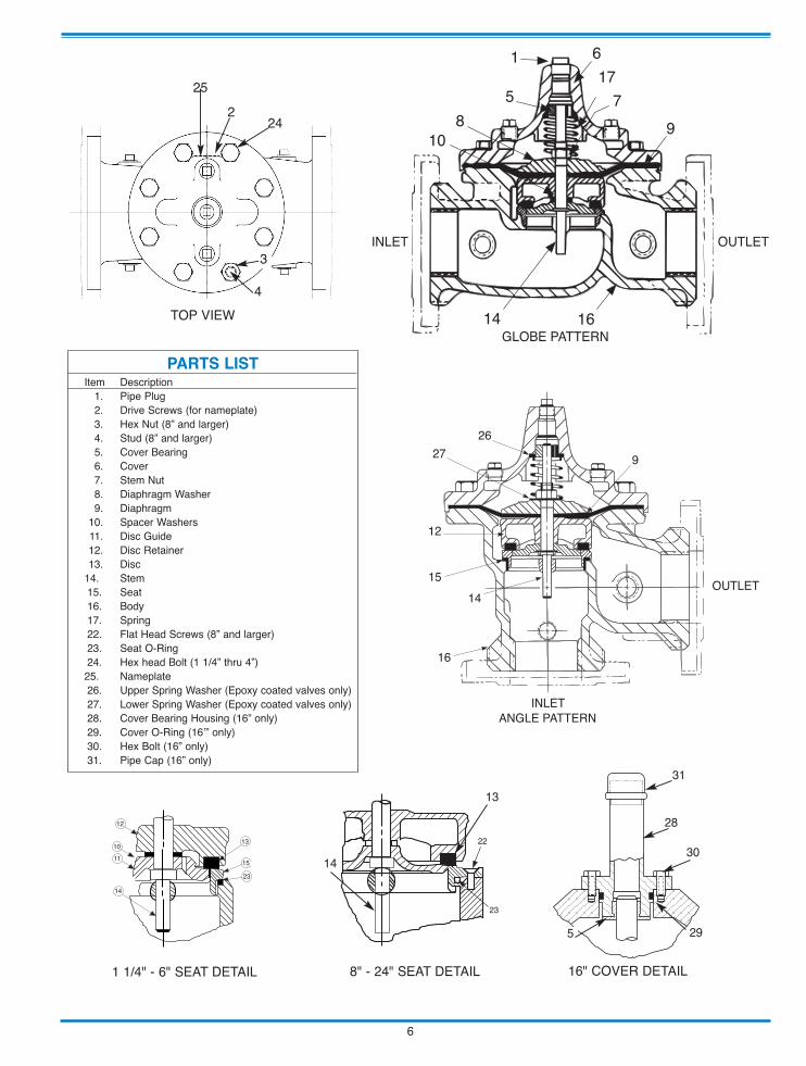
Item Description1. Pipe Plug2. Drive Screws (for nameplate)3. Hex Nut (8” and larger)4. Stud (8” and larger)5. Cover Bearing6. Cover7. Stem Nut8. Diaphragm Washer9. Diaphragm
10. Spacer Washers11. Disc Guide12. Disc Retainer13. Disc
14. Stem15. Seat16. Body17. Spring22. Flat Head Screws (8” and larger)23. Seat O-Ring24. Hex head Bolt (1 1/4” thru 4”)25. Nameplate26. Upper Spring Washer (Epoxy coated valves only)27. Lower Spring Washer (Epoxy coated valves only)28. Cover Bearing Housing (16” only)29. Cover O-Ring (16’” only)30. Hex Bolt (16” only)31. Pipe Cap (16” only)
PARTS LIST
6

100-
01H
ytro
l Val
ve S
ervi
ce D
ata
MO
DEL
INST
ALL
ATIO
N /
OPE
RAT
ION
/ M
AIN
TEN
AN
CE
Des
crip
tion
100-
01 H
ytro
l Val
veTh
e C
Ia-V
aI M
odel
100
-01
Hyt
rol
Valv
e is
a m
ain
valv
e fo
rC
Ia-V
aI A
utom
atic
Con
trol V
alve
s. It
is a
hyd
raul
ical
ly o
pera
ted,
diap
hrag
m-a
ctua
ted,
glo
be o
r ang
le p
atte
rn v
alve
.
This
val
ve c
onsi
sts
of th
ree
maj
or c
ompo
nent
s; b
ody,
dia
phra
gmas
sem
bly,
and
cov
er.
The
diap
hrag
m a
ssem
bly
is t
he o
nly
mov
ing
part.
The
dia
phra
gm a
ssem
bly
uses
a d
iaph
ragm
of n
ylon
fabr
ic b
onde
d w
ith s
ynth
etic
rub
ber.
A sy
nthe
tic r
ubbe
r di
sc,
cont
aine
d on
thre
e an
d on
e ha
lf si
des
by a
dis
c re
tain
er a
nd d
isc
guid
e, fo
rms
a se
al w
ith th
e va
lve
seat
whe
n pr
essu
re is
app
lied
abov
e th
e di
aphr
agm
. The
dia
phra
gm a
ssem
bly
form
s a
seal
edch
ambe
r in
the
uppe
r po
rtion
of t
he v
alve
, sep
arat
ing
oper
atin
gpr
essu
re fr
om li
ne p
ress
ure.
Des
crip
tion
100-
20 6
00 S
erie
s H
ytro
l Val
veTh
e C
Ia-V
aI M
odel
100
-20
Hyt
rol V
alve
(600
Ser
ies
mai
n va
lve)
have
onl
y on
e pa
rt -th
e bo
dy- t
hat i
s di
ffere
nt fr
om s
tand
ard
100
Serie
s C
la-V
al m
ain
valv
e pa
rts.
The
rem
aini
ng p
arts
of t
he 6
00se
ries
mai
n va
lve
are
stan
dard
Cla
-Val
mai
n va
lve
parts
. Al
l ser
v-ic
e an
d m
aint
enan
ce i
nfor
mat
ion
for
the
stan
dard
100
Ser
ies
mai
n va
lves
als
o ap
ply
to th
e 60
0 se
ries
mai
n va
lves
.
The
mos
t im
porta
nt th
ing
to re
mem
ber w
hen
orde
ring
mai
nva
lve
repa
ir ki
ts a
nd re
plac
emen
t par
ts, e
xcep
t for
the
body
, all
othe
r par
ts a
re g
oing
to b
e fo
r a s
mal
ler s
ize
mai
n va
lve.
Cla
-Va
l ide
ntifi
es m
ain
valv
e pa
rts w
ith th
e fla
nge
size
of t
he s
tan-
dard
100
Ser
ies
mai
n va
lve.
Ref
er to
the
"Mai
n Va
lve
Size
s”ch
art b
elow
.
HYT
RO
L Se
rvic
e D
ata
HYT
RO
L SI
ZESt
emTr
avel
Cov
er C
apac
ityD
ispl
acem
ent
Valv
e St
emTh
read
UN
F-In
tern
al
Cov
erC
ente
rPl
ugN
PT
Cov
er N
ut o
r Bol
tC
over
Lifti
ngH
oles
UN
C
Cov
er P
lug
Cov
er T
orqu
eSt
em N
ut**
Stem
Nut
Tor
que
(ft. L
bs.)
100-
0110
0-20
Thre
ad(B
olt)
Sock
etQ
tyTh
read
Sock
etft.
Lbs
.in
. Lbs
.Th
read
Sock
et(L
ong)
inch
esm
min
ches
mm
inch
esm
mG
allo
nsLi
ters
Lube
dD
RY
1"25
0.3
81/
4"1/
4" -
20 (B
)7/
16"
84
483/
8" -
244
61
1/4"
320.
410
0.02
00.
0710
- 32
1/4"
5/16
" - 1
8 (B
)1/
2"8
896
7/16
" -20
610
1 1/
2"40
0.4
100.
020
0.07
10 -
321/
4"5/
16" -
18
(B)
1/2"
88
967/
16" -
206
102"
500.
615
0.03
20.
1210
- 32
1/2"
3/8"
- 16
(B)
9/16
"8
3/8"
7/16
"12
1/2"
- 20
3/4"
1015
2 1/
2"65
0.7
180.
043
0.16
10 -
321/
2"7/
16" -
14
(B)
5/8"
81/
2"9/
16"
205/
8" -
1815
/16"
2130
3"80
4"10
00.
820
0.08
00.
301/
4 - 2
81/
2"1/
2" -
13 (B
)3/
4"8
1/2"
9/16
"30
5/8"
- 18
15/1
6"21
304"
100
6"15
01.
123
0.16
90.
641/
4 - 2
83/
4"3/
4" -
10 (B
)1
1/8"
83/
4"5/
8"11
03/
4" -
161
1/16
"40
606"
150
8"20
01.
743
0.53
12.
003/
8 - 2
43/
4"3/
4" -
10 (B
)1
1/8"
123/
4"5/
8"11
07/
8" -
141
5/16
"85
125
8"20
010
"25
02.
358
1.26
4.80
3/8
- 24
1"3/
4" -
101
1/4"
165/
8" -
111"
13/1
6"11
01
1/8"
-12
1 13
/16"
125
185
10"
250
12"
300
2.8
712.
519.
503/
8 - 2
41"
7/8"
- 9
1 7/
16"
203/
4" -
101"
13/1
6"16
01
1/2"
-12
1 7/
8"25
237
512
"30
016
"40
03.
486
4.0
15.1
03/
8 - 2
41
1/4"
1 1/
8" -
71
13/1
6"20
3/4"
- 10
1"13
/16"
390
1 1/
2" -1
22
1/2"
270
400
14"
350
3.9
996.
524
.60
3/8
- 24
1 1/
2"1
1/4"
- 7
2"20
1" -
81"
13/1
6"54
51
1/2"
-12
2 1/
2"28
042
016
"40
020
", 24
"60
04.
511
49.
636
.20
1/2
- 20
2"1
1/4"
- 7
2"20
1" -
81"
13/1
6"54
52"
- 16
3"50
075
020
"50
05.
6314
312
45.4
03/
4 - 1
61
1/2"
1 3/
8" -
62
1/8"
241"
- 8
1"13
/16"
670
2 1/
4" -
163
1/2"
930
N/R
24"
600
30"
800
6.75
165
29.0
108.
803/
4 - 1
6*3/
4"1
1/2"
- 12
2 3/
8"24
1 1/
8"- 7
1"13
/16"
800
3" -
12Sp
ecia
l13
50N
/R* A
dapt
erp/
n 25
9410
1Ein
side
1/4
" - 2
8"
Gra
de 5
Bol
ts"H
eavy
" Gra
de N
uts
Tigh
ten
cove
r nut
s in
a "s
tar"
cros
s-ov
er p
atte
rn
** M
ust U
se O
NLY
Cla
-Val
Sup
plie
d pa
r t

CLA-VAL
C
opyr
ight
Cla
-Val
201
4 P
rinte
d in
USA
Sp
ecific
atio
ns s
ubje
ct to
cha
nge
with
out n
otice
.
P.O
. Box
132
5 •
Newp
ort B
each
, CA
9265
9-03
25 •
Pho
ne: 9
49-7
22-4
800 •
Fax:
949
-548
-544
1 •
E-m
ail:
clava
l@cla
-val
.com
• W
ebsit
e cla
-val
.com
©
COVE
R PI
PE P
LUG
COVE
R BE
ARIN
G SP
RING
STEM
NUT
DIAP
HRAG
M W
ASHE
R
DISC
RET
AINE
R
BODY
*SPA
CER
WAS
HERS
DISC
GUI
DE
SEAT
PIPE
PLU
G
STEM
SEAT
O-R
ING
STUD
8"
and
Lar
ger
*DIA
PHRA
GM
*DIS
C
*Rep
air P
arts
Seat
Scr
ew
8" a
nd L
arge
r
(Glob
e or
Ang
le)
PIPE
PLU
G
HEX
NU
T 8"
and
Lar
ger
Cove
r Bol
t 6"
and
Sm
alle
r
K
O DI
SC G
UIDE
KO
SE
AT
KO A
nti-C
avita
tion
T
rim O
ptio
n
N-1
00-0
1 (R
-08/
2014
)
BOLT
/NU
T TO
RQ
UIN
G P
RO
CED
UR
ES O
N V
ALVE
CO
VER
S
4BO
LTS
6BO
LTS
8BO
LTS
12BO
LTS
16BO
LTS
20BO
LTS
4
3 2
1
65
4
3 2
1
8
7
6
5
4
3
2
1
0
9
8
7
6
5
4
3
2
112
1110
9
8
76
5
4
3
2
116
1514
13
12
11
10
9
8
7
6
5 4
3
2
120
1918
17
16
15
14
1312
11
Follo
w th
is p
roce
dure
whe
n re
asse
mbl
ing
MAI
N V
alve
:
1. T
ight
ens
bolts
/nut
s in
a “S
tar”
or “C
ross
-Ove
r” pa
ttern
follo
win
g th
e nu
mbe
rs s
how
n ab
ove
to in
sure
that
cov
er s
eats
eve
nly
on th
e di
aphr
agm
mat
eria
l and
bod
y.
2. T
orqu
e th
e bo
lt/nu
ts in
thre
e st
ages
with
a "S
tar"
or "C
ross
-Ove
r" pa
ttern
for e
ach
stag
e:
A. T
o ap
prox
imat
ely
10%
of f
inal
torq
ue.
B. T
o ap
prox
imat
ely
75%
of f
inal
torq
ue.
C. T
o fin
al re
quire
d to
rque
.
3. V
alve
s th
at a
re to
be
test
ed to
375
PSI
or h
ighe
r sho
uld
be re
torq
ued
afte
r 24
hour
s.
100-
01 H
ytro
l Mai
n Va
lve
Asse
mbl
y

UNDERSTANDING THE 600 SERIES VALVES
In 1987, Cla-Val introduced the Model 100-20 Hytrol as the basicmain valve for the 600 Series of automatic control valves. Toidentify all new valves using the 100-20 Hytrol, an existing cata-log number is modified. Making a 600 Series catalog number issimply done by using a "6" in front of the two digit catalog num-bers or replacing the "2" with a "6" in three digit catalog num-bers. Current schematics reflect both catalog numbers togetherseparated by a slash ( i.e. - 90-01/690-01, 58-02/658-02, 210-01/610-01, etc). Since these two valves 'share' the same catalognumber and schematic, they provide the same function in a sys-tem. The only difference between the two valves is the relativecapacity of the two main valve series.
The 100-01 Hytrol is the basic main valve for Cla-Val automaticcontrol valves. This valve is the current version of the ClaytonHytrol valve design originated in 1936. The 100-01 Hytrol isdesigned as a full flow area valve. This means that the inlet,seat and outlet openings are the same size. Thus, the pressuredrop is kept to a minimum for this globe style design.
The 100-20 Hytrol valve has all of the basic features and advan-tages of the original 100-01 Hytrol. Only one part has beenchanged - the body. It is designed with different size inlet, seatand outlet openings. The 100-20 Hytrol has inlet and outletflanges one valve size larger than the seat opening size. Thisresults in what is sometimes called a ''reduced port' main valve.For example, a 4" 100-20 valve has a 3" seat. Note: valve sizeis always determined by the flange size. The following chartcompares the 100-01 and the 100-20 main valves.
600 Series Hytrol Valve100-20MODEL
INSTALLATION / OPERATION / MAINTENANCE
SERVICE AND MAINTENANCE OF 600 SERIESVALVES
The 600 series main valves have only one part -the body- that isdifferent from standard 100 Series Cla-Val main valve parts. Theremaining parts of the 600 series main valve are standard Cla-Val main valve parts. All service and maintenance informationfor the standard 100 Series main valves in this manual alsoapply to the 600 series main valves.
The most important thing to remember when ordering main valverepair kits and replacement parts, except for the body, all otherparts are going to be for a smaller size main valve. Cla-Val iden-tifies main valve parts with the flange size of the standard 100Series main valve. Refer to the "Main Valve Sizes Comparison"chart. For example, if you are servicing a 6" 100-20 Hytrol andneeded a repair kit, you would order a repair kit for a 4" 100-01Hytrol. This kit is also suitable for a 6" 100-20 Hytrol. CompleteTechnical Manuals include a repair kit data sheet N-RK thatshows this relationship.
When you order repair parts, it is a good idea to include valvenameplate data (size, catalog number, and part number) anddescription of the parts desired. Do this to be sure parts will fitthe valve you are working on and not be too big for it. Pilot con-trols and repair kits maintenance information remain the samefor 100 or 600 Series valves.
Cla-Val Main ValvesCatalog Number
The 100-20 Hytrol is available only in ductile iron, 150 and 300pressure class, and Bronze trim standard. Available extra costmain valve options include stainless steel trim, epoxy coating,Dura-Kleen stem, Delrin sleeved stem, and high temperature rub-ber parts. All four basic main valves have a 600 Series versionavailable with all of the same benefits and size relationships.The following chart shows the relationship of Cla-Val main valvecatalog numbers.
Catalog Name
Hytrol
Powertrol
Powercheck
Hycheck
Circa 1936
100 (Angle =2100)
100P & 100PA
100PC & 100PCA
181
100-Series
100-01
100-02
100-03
100-04
600 Series
100-20
100-21
100-22
100-23
(Reduced Internal Port)
Basic Main Valve Size ComparisonGlobe Pattern Valves
Flange Size (inch) Seat Size100-01 (100 Series) 100-20 (600 Series)
3 3 24 4 36 6 48 8 610 10 812 12 1014 14 ----16 16 1218 ---- 1620 20 1624 24 1630 30 2436 36 3042 ---- 3648 ---- 36
Angle Pattern Valves
Flange Size (inch) Seat Size100-01 (100 Series) 100-20 (600 Series)
4 4 36 6 48 8 6

CLA-VAL Copyright Cla-Val 2011 Printed in USA Specifications subject to change without notice. P.O. Box 1325 • Newport Beach, CA 92659-0325 • Phone: 949-722-4800 • Fax: 949-548-5441 • E-mail: [email protected] • Website cla-val.com
©N-100-20 (R-3/2011)
100-20 PARTS LIST
NO. DESCRIPTION
1 Pipe Plug
2 Drive Screws (for nameplate)
3 Hex Nut (8" and larger)
4 Stud (8" and larger)
5 Cover Bearing
6 Cover
7 Stem Nut
8 Diaphragm Washer
9 Diaphragm
10 Spacer Washers
11 Disc Guide
12 Disc Retainer
13 Disc
14 Stem
15 Seat
16 Body
17 Spring
22 Flat Head Screws (10" and larger)
23 Seat O-Ring
24 Hex Bolt (3 " Thru 6")
25 Nameplate (Mounted on inlet flange)
26 Upper Spring Washer (Epoxy coated valves only)
27 Lower Spring Washer (Epoxy coated valves only)
28 Cover Bearing Housing (20" & 24" & 30")
29 Cover Bearing Housing O-Ring (20"& 24" & 30")
30 Hex Bolt (20" & 24")
31 Pipe Cap (20" & 24 & 30"")11
14
1 24 3 4
517
16
26
14
78
9
27
1413
22
12
15
31
28
5
30
29
10" — 24" SEAT DETAIL 20" — 24" COVER DETAIL
TOP VIEW
12
13
15
OUTLETGLOBEINLET
ANGLEINLET
6
8
9
2
25
3" — 6" COVER DETAIL
2311
WHEN ORDERING PARTS, BE SURE TO GIVE COMPLETENAMEPLATE DATA, ITEM NUMBER AND DESCRIPTION.
10
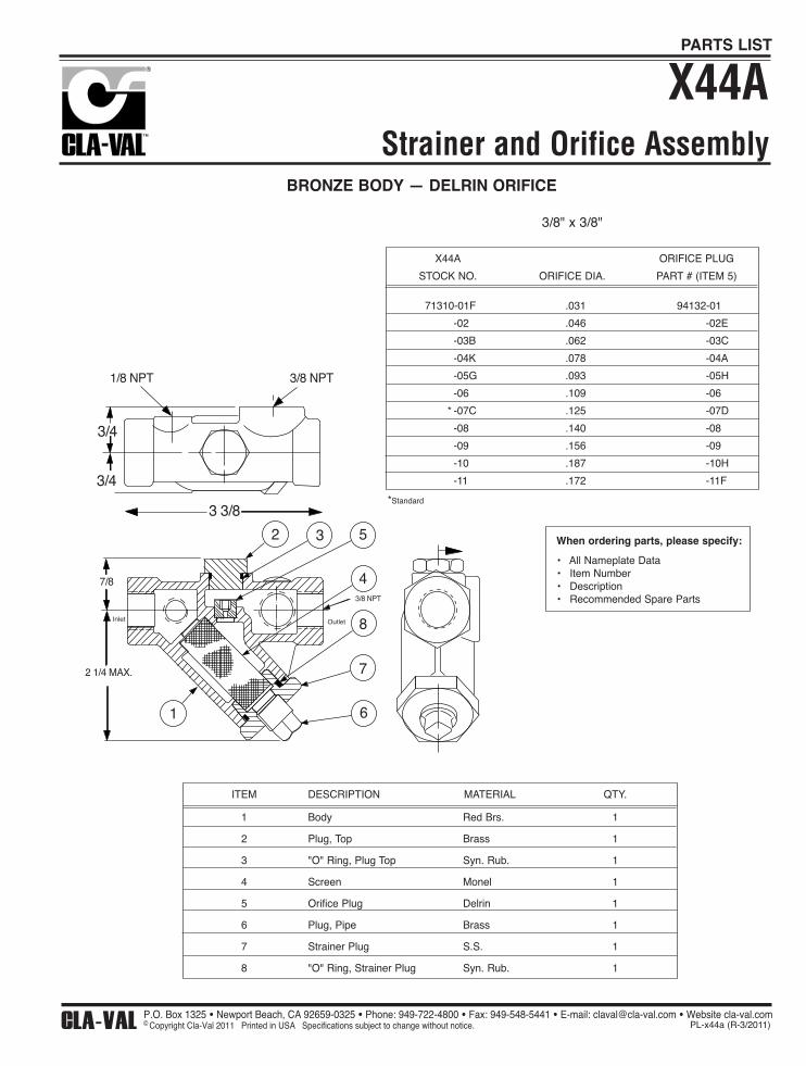
When ordering parts, please specify:
• All Nameplate Data• Item Number • Description• Recommended Spare Parts
Strainer and Orifice Assembly
X44A
BRONZE BODY — DELRIN ORIFICE
1/8 NPT 3/8 NPT
3/4
3/4
3 3/8
2 3 5
43/8 NPT
8
7
61
2 1/4 MAX.
7/8
Inlet Outlet
X44A
STOCK NO.
71310-01F
-02
-03B
-04K
-05G
-06
* -07C
-08
-09
-10
-11
ORIFICE DIA.
.031
.046
.062
.078
.093
.109
.125
.140
.156
.187
.172
ORIFICE PLUG
PART # (ITEM 5)
94132-01
-02E
-03C
-04A
-05H
-06
-07D
-08
-09
-10H
-11F
*Standard
3/8" x 3/8"
ITEM
1
2
3
4
5
6
7
8
DESCRIPTION
Body
Plug, Top
"O" Ring, Plug Top
Screen
Orifice Plug
Plug, Pipe
Strainer Plug
"O" Ring, Strainer Plug
MATERIAL
Red Brs.
Brass
Syn. Rub.
Monel
Delrin
Brass
S.S.
Syn. Rub.
QTY.
1
1
1
1
1
1
1
1
CLA-VAL Copyright Cla-Val 2011 Printed in USA Specifications subject to change without notice. P.O. Box 1325 • Newport Beach, CA 92659-0325 • Phone: 949-722-4800 • Fax: 949-548-5441 • E-mail: [email protected] • Website cla-val.com
© PL-x44a (R-3/2011)
PARTS LIST

DESCRIPTIONThe Cla-Val Model CRD Pressure Reducing Control automatically reducesa higher inlet pressure to a lower outlet pressure. It is a direct acting,spring loaded, diaphragm type control that operates hydraulically or pneu-matically. It may be used as a self-contained valve or as a pilot control fora Cla-Val main valve. It will hold a constant downstream pressure withinvery close pressure limits.OPERATIONThe CRD Pressure Reducing Control is normally held open by the force ofthe compression spring above the diaphragm; and delivery pressure actson the underside of the diaphragm. Flow through the valve responds tochanges in downstream demand to maintain a pressure.INSTALLATIONThe CRD Pressure Reducing Control may be installed in any position.There is one inlet port and two outlets, for either straight or angle installa-tion. The second outlet port can be used for a gage connection. A flowarrow is marked on the body casting.ADJUSTMENT PROCEDUREThe CRD Pressure Reducing Control can be adjusted to provide a deliv-ery pressure range as specified on the nameplate.Pressure adjustment is made by turning the adjustment screw to vary thespring pressure on the diaphragm. The greater the compression on thespring the higher the pressure setting.
1. Turn the adjustment screw in (clockwise) to increase delivery pressure.2. Turn the adjustment screw out (counter-clockwise) to decrease the delivery pressure.3. When pressure adjustment is completed tighten jam nut on adjusting screw and replace protective cap.4. When this control is used, as a pilot control on a Cla-Val main valve, the adjustment should be made under flowing conditions. The flow rate is not critical, but generally should be somewhat lower than normal in order to provide an inlet pressure several psi higher than the desired setting
CRD
MAINTENANCEDisassemblyTo disassemble follow the sequence of the item numbers assigned toparts in the sectional illustration.ReassemblyReassembly is the reverse of disassembly. Caution must be taken toavoid having the yoke (17) drag on the inlet nozzle of the body (18).Follow this procedure:
1. Place yoke (17) in body and screw the disc retainer assembly (16) until it bottoms.
2. Install gasket (14) and spring (19) for 2-30 and 2-6.5 psi range onto plug (13) and fasten into body. Disc retainer must enter guide hole in plug as it is assembled. Screw the plug in by hand. Use wrench to tighten only.
3. Place diaphragm (12) diaphragm washer (11) and belleville washer (20) on yoke. Screw on hex nut (10).
4. Hold the diaphragm so that the screw holes in the diaphragm and body align. Tighten diaphragm nut with a wrench. At the final tightening release the diaphragm and permit it to rotate 5° to 10°. The diaphragm holes should now be properly aligned with the body holes.
To check for proper alignment proceed as follows:Rotate diaphragm clockwise and counterclockwise as far as possible.Diaphragm screw holes should rotate equal distance on either side ofbody screw holes ±1/8".Repeat assembly procedure until diaphragm and yoke are properlyaligned. There must be no contact between yoke and body nozzleduring its normal movement. To simulate this movement hold bodyand diaphragm holes aligned. Move yoke to open and closed posi-tions. There must be no evidence of contact or dragging.
5. Install spring (9) with spring guide (8).6. Install cover (5), adjusting screw (2) and nut (3), then cap (1).
Pressure Reducing Control
The approximate minimum flow rates given in the table are for the main valveon which the CRD is installed.
Valve SizeMinimum Flow GPM
1 1/4" -3" 4"-8" 10"-16"1-2 4-15 35-95
MODEL
INSTALLATION / OPERATION / MAINTENANCE
CLA-VAL Copyright Cla-Val 2019 Printed in USA Specifications subject to change without notice. 1701 Placentia Ave • Costa Mesa CA 92627 Phone: 949-722-4800 • Fax: 949-548-5441 • E-mail: [email protected] • www.cla-val.com
© N-CRD (R-01/2019)
SYMPTOM PROBABLE CAUSE REMEDY
Fails to openwhen deliver pres-
sure lowers
No spring compression Tighten adjusting screw
Damaged spring Disassemble and replace
Spring guide (8) is not in place Assemble properly
Yoke dragging on inlet nozzle Disassemble and reassembleproperly (refer to Reassembly)
Fails to closewhen deliverypressure rises
Spring compressed solid Back off adjusting screw
Mechanical obstruction Disassemble and reassembleproperly (refer to Reassembly)
Worn disc Disassemble remove andreplace disc retainer assembly
Yoke dragging on inlet nozzle Disassemble and reassembleproperly (refer to Reassembly)
Leakage fromcover vent hole
Damaged diaphragm Disassemble and replace
Loose diaphragm nut Remove cover and tighten nut

Pressure Reducing Control(Bronze Body with 303SS Trim)
*SUGGESTED REPAIR PARTS
CRD
3 1/8
PRESSURE SETTINGADJUSTING SCREW(TURN CLOCKWISETO INCREASE SETTING
SECTION A-AOPEN POSTIONFOR HIGH PRESSURE CONTROL
5 3/8
1 13/16
inlet
B13 14
16
18
17
12
11
10
9
8
5
3
12
cover vent
B
3/8" NPT
16
19
Body and DiscRetainer Detail
for Low Pressure Control
SECTION B-BCLOSED POSITION
20
18
17
15
4
A A
67
When ordering parts specify:
• All nameplate data• Item Description• Item number
CLA-VAL Copyright Cla-Val 2019 Printed in USA Specifications subject to change without notice. 1701 Placentia Ave • Costa Mesa CA 92627 Phone: 949-722-4800 • Fax: 949-548-5441 • E-mail: [email protected] • www.cla-val.com
© PL-CRD (R-09/2019)
PARTS LIST
Size(inch)
StockNumber
Adjustment Rangepsi Ft of Water
3/8 7194307A 2 - 6.5 4.5 - 153/8 7194308J 2 - 30 4.5 - 693/8 7194303K 15 - 75 35 - 1733/8 7194311C 20 - 105 46 - 2423/8 7194304H 30 - 300 69 - 692
Factory Set Pressure PSI per Turn*2 - 6.5 set @ 3.5 psi .612 - 30 set @ 10 psi 3.0
15 - 75 set @ 20 psi 9.020 - 105 set @ 60 psi 12.030 - 300 set @ 60 psi 27.0
*Approximate-Final Adjustment should be with a pressure gauge and with flow.
Item Description Material Part Number1 Cap PL 67628J2 Adjusting Screw BRS 7188201D3 Jam Nut (3/8-16) SS 6780106J4* Machine Screw (Fil.Hd.) 8 Req'd 303 6757821B5 Cover BRS C2544K6 Nameplate Screw SS 67999D7 Nameplate BRS C0022001G8 Spring Guide 302 71881H
Spring Guide (20 - 105 psi) 303 205620F9 Spring (15-75 psi) CHR/VAN 71884B
Spring (2 - 6.5 psi) SS 82575CSpring (2 - 30 psi) SS 81594ESpring (20 - 105 psi) 316 20632101ESpring (30 - 300 psi) CHR/VAN 71885J
10 Hex Nut 303 71883D11 Diaphragm Washer 302 71891G12* Diaphragm NBR C6936D13 Plug, Body BRS V5653A14* Gasket Fiber 40174F15 Plug BRS 6766003F16* Disc Retainer Assy. (2 - 30 psi) SS/Rub C8348K
Disc Retainer Assy. (15 - 75 psi) SS/Rub 37133GDisc Retainer Assy. (20 - 105 psi) SS/Rub 37133GDisc Retainer Assy. (30 - 300 psi) SS/Rub 37133G
17 Yoke VBZ V6951H18 Body & 1/4" Seat Assy BR/SS 8339702G19* Bucking Spring (2 - 6.5 psi)(2 - 30psi) 302 V0558G20 Belleville Washer STL 7055007E* Repair Kit (No Bucking Spring) Buna®-N 9170003K* Repair Kit (with Bucking Spring) Buna®-N 9170002B

DESCRIPTIONThe CRL Pressure Relief Control is a direct acting, spring loaded,diaphragm type relief valve. It may be used as a self-contained valve oras a pilot control for a Cla-Val Main valve. It opens and closes withinvery close pressure limits.INSTALLATIONThe CRL Pressure Relief Control may be installed in any position. Thecontrol body (7) has one inlet and one outlet port with a side pipe plug(24) at each port. These plugs are used for control connections or gaugeapplications. The inlet in the power unit body (6) is the sensing line port.A flow arrow is marked on the body casting.OPERATIONThe CRL Pressure Relief Control is normally held closed by the force ofthe compression spring above the diaphragm; control pressure is appliedunder the diaphragm.When the controlling pressure exceeds the spring setting, the disc is liftedoff its seat, permitting flow through the control.When controlling pressure drops below spring setting, the spring returnsthe control to its normally closed position.ADJUSTMENT PROCEDUREThe CRL Pressure Relief Control can be adjusted to provide a relief set-ting at any point within the range found on the nameplate.Pressure adjustment is made by turning the adjustment screw (9) to varythe spring pressure on the diaphragm. Turning the adjustment screwclockwise increases the pressure required to open the valve.Counterclockwise decreases the pressure required to open the valve.When pressure adjustments are complete the jam nut (10) should betightened and the protective cap (1) replaced. If there is a problem oftampering, lock wire holes have been provided in cap and cover. Wirethe cap to cover and secure with lead seal.DISASSEMBLYThe CRL Pressure Relief Control does not need to be removed from theline for disassembly. Make sure that pressure shut down is accompaniedprior to disassembly. If the CRL is removed from the line for disassemblybe sure to use a soft jawed vise to hold body during work.Refer to Parts List Drawing for Item Numbers.1. Remove cap (1), loosen jam nut (10) and turn adjusting
screw counterclockwise until spring tension is relieved.2. Remove the eight screws (4) holding the cover (3) and
powerunit body (6). Hold the cover and powerunit together and place on a suitable work surface. See NOTE under REASSEMBLY.
3. Remove the cover (3) from powerunit body (6). The spring (12) and two spring guides (11).
4. Remove nut (13) from stem (19) and slide off the belleville washer (14), the upper diaphragm washer (15) and the diaphragm (16).
5. Pull the stem (19) with the disc retainer assembly (21) through the bottom of powerunit. The lower diaphragm washer (17) will slide off of stem top.
6. Remove jam nut (23) and disc retainer assembly (21) from stem. Use soft jawed pliers or vise to hold stem. The polished surface of stem must not be scored or scratched.
7. The seat (22) need not be removed unless it is damaged. If removal is necessary use proper size socket wrench and turn counterclockwise.Note: Some models have an integral seat in the body (7).
INSPECTIONInspect all parts for damage, or evidence of cross threading. Checkdiaphragm and disc retainer assembly for tears, abrasions or other dam-age. Check all metal parts for damage, corrosion or excessive wear.REPAIR AND REPLACEMENTMinor nicks and scratches may be polished out using 400 grit wet or drysandpaper fine emery or crocus cloth. Replace all O-rings and any dam-aged parts.When ordering replacement parts, be sure to specify parts list item num-ber and all nameplate data.REASSEMBLYIn general, reassembly is the reverse of disassembly. However, the fol-lowing steps should be observed:1. Lubricate the O-Ring (18) with a small amount of a good grade of waterproof grease, (Dow Corning 44 medium grade or equal). Use grease sparingly and install O-ring in powerunit body (6).
2. Install stem (19) in powerunit body (6). Use a rotating motion with minimum pressure to let stem pass through O-ring. Do Not Cut O-Ring.
3. Install O-ring (5) at top of stem (19). Place lower diaphragm washer (17) on the stem with the serrated side up. Position diaphragm (16), upper diaphragm washer (15), with serration down, and belleville washer (14) with concave side down.
4. Position powerunit body (6) as shown on parts list drawing (top view).5. Continue reassembly as outlined in disassembly steps 1 through 3.
Pressure Relief ControlCRL
Note: Item (4) Screw will have a quantity of 8 for the 0-75 and 20-200psidesign and a quantity of 4 for the 100-300psi design. Item (25) Screw isused on the 100-300psi design only. Install item (25), before item (4) forpreload of item (12) spring.
SYMPTOM PROBABLE CAUSE REMEDY
Fails to open. Controlling pressuretoo low.
Back off adjustingscrew until valveopens.
Fails to open withspring compressionremoved.
Mechanical obstruc-tion, corrosion, scalebuild-up on stem.
Disassemble,locate,and removeobstruction, scale.
Leakage from covervent hole when con-trolling pressure isapplied.
Diaphragm Damage Disassembly replacedamageddiaphragm.
Fails to close withspring compressed.
Mechanical obstruc-tion.
Disassemble, locateand removeobstruction.
Fails to close. No spring compres-sion.
Re-set pressureadjustment.
Loose diaphragmassembly.
Tighten upperdiaphragm washer.
MODEL
INSTALLATION / OPERATION / MAINTENANCE
CLA-VAL Copyright Cla-Val 2021 Printed in USA Specifications subject to change without notice. 1701 Placentia Ave • Costa Mesa CA 92627 Phone: 949-722-4800 • E-mail: [email protected] • www.cla-val.com
© N-CRL (R-3/2011)

1/2" & 3/4" PRESSURE RELIEF CONTROL(Bronze Body with 303SS Trim)
CRL
Ajusting Screw(3/8" - 16UNF THREAD)
9
1
103111214
13 11
8 22 23 7
181921INLET
1/8 - 27 NPTSENSINGCONNECTION(TYP.)
7.44MAX
.71
OUTLET 2062
0 TO 75 AND20 TO 200 PSI
DESIGN
51716
154
191031112
11
18
7
2
100 To 300 psi Design
.71
ADJUSTING SCREW(1/2" 20UNF THREAD)
10.44MAX.
When ordering parts please specify:1. All Nameplate Data 2. Item Part Number3. Item Description
24
4
45º
3.12 DIA.
TRUE LOCATION OF SENSING CONNECTION (TYP.)
Body withintegral Seat
CLA-VAL Copyright Cla-Val 2021 Printed in USA Specifications subject to change without notice. 1701 Placentia Ave • Costa Mesa CA 92627 Phone: 949-722-4800 • E-mail: [email protected] • www.cla-val.com
© PL-CRL (R-01/2021)
PARTS LIST
Item Description Material Part Number Part Number Part Number Part Number0-75 20-105 20-200 100-300
1 Cap Plastic 67628J 67628J 67628J 1257601D2 Nameplate Brass -- -- -- --3 Cover Bronze C2544K C2544K C2544K 44587E4* Screw Fil. Hd. 10-32 x 1.88 (Qty 8) 303 SS 6757867E 6757867E 6757867E 6757867E5* O-Ring Rubber 00902H 00902H 00902H 00902H6 Body, Powerunit Bronze 7920504D 7920504D 7920504D 7920504D7 1/2” Body Bronze C7928K C7928K C7928K C7928K
3/4” Body Bronze C9083B C9083B C9083B C9083B8* O-Ring, Seat Rubber 00718H 00718H 00718H 00718H9 Screw, Adjusting Brass 7188201D 7188201D 7188201D 82811B10 Nut Hex (Locking) 303 SS 6780106J 6780106J 6780106J 6780606H11 Guide, Spring 303 SS 71881H 71881H 71881H 1630301J12 Spring CHR/VAN 71884B 20632101E 71885J 1630201A13 Nut, Stem Upper Bronze 73034B 73034B 73034B 73034B14 Washer, Belleville Steel 7055007E 7055007E 7055007E 7055007E15 Washer, Diaphragm (upper) 303 SS 71891G 71891G 71891G 71891G16* Diaphragm Rubber C1505B C1505B C1505B C1505B17 Washer, Diaphragm (lower) 303 SS 45871B 45871B 45871B 45871B18* O-Ring, Stem Rubber 00746J 00746J 00746J 00746J19 Stem 303 SS 8982401F 8982401F 8982401F 8982401F20* O-Ring, Body Rubber 00767E 00767E 00767E 00767E21* Retainer Assembly, Disc 303 SS C9158B C9158B C9158B C9158B22 Seat 303Rub 62187A 62187A 62187A 62187A23 Nut, Hex, Stem, Lower Bronze 6779806G 6779806G 6779806G 6779806G24 Pipe Plug Bronze 6784701C 6784701C 6784701C 6784701C
FACTORY SET POINT 50 PSI 60 PSI 60 PSI 100 PSIREPAIR KIT* 9170007A 9170007A 9170007A 9170007A
CRLRange PSI
APPROX. INCREASEFOR EACH
CLOCKWISE TURN OF ADJUSTING SCREW
0 to 75 8.5 PSI20 to 105 12.5 PSI20 to 200 28.0 PSI100 to 300 18.0 PSI
SIZE SPRING PARTNUMBER
1/2” 0-75 PSI 7922201E1/2” 20-105 PSI 7922205F1/2” 20-200 PSI 7922202C1/2” 100-300 PSI 8280901D3/4” 0-75 PSI 7922901K3/4” 20-105 PSI 7922903F3/4” 20-200 PSI 7922902H3/4” 100-300 PSI 8600501EFor 250-600 PSI Contact Factory

CLA-VAL Copyright Cla-Val 2021 Printed in USA Specifications subject to change without notice. 1701 Placentia Ave • Costa Mesa CA 92627 Phone: 949-722-4800 • E-mail: [email protected] • www.cla-val.com
©
INSTALLATION / OPERATION / MAINTENANCE
Flow ControlCVMODEL
N-CV (R-03/2021)
DESCRIPTIONThe CV Control is an adjustable restriction which acts as aneedle valve when flow is in the direction of the stem. Whenflow is in the reverse direction, the port area opens fully toallow unrestricted flow. When installed in the control system ofa Cla-Val automatic valve, it can be arranged to function aseither an opening or closing speed control.
OPERATIONThe CV Flow Control permits full flow from port A to B, andrestricted flow in the reverse direction. Flow from port A to Blifts the disc from seat, permitting full flow. Flow in the reversedirection seats the disc, causing fluid to pass through the clear-ance between the stem and the disc. This clearance can beincreased, thereby increasing the restricted flow, by screwingthe stem out, or counter-clockwise. Turning the stem in, orclockwise reduces the clearance between the stem and thedisc, thereby reducing the restricted flow.’
INSTALLATIONInstall the CV Flow Control as shown in the valve schematicAll connections must be tight to prevent leakage.
DISASSEMBLYFollow the sequence of the item numbers assigned to theparts in the cross sectional illustration for recommendedorder of disassembly.Use a scriber, or similar sharp-pointed tool to remove O-ringfrom the stem.
INSPECTIONInspect all threads for damage or evidence of cross-threading. Check mating surface of seat and valve disc forexcessive scoring or embedded foreign particles. Checkspring for visible distortion, cracks and breaks. Inspect allparts for damage, corrosion and cleanliness.
CLEANING After disassembly and inspection, cleaning of the parts canbegin. Water service usually will produce mineral or limedeposits on metal parts in contact with water. Thesedeposits can be cleaned by dipping the parts in a 5-percentmuriatic acid solution just long enough for deposits to dis-solve. This will remove most of the common types ofdeposits. Caution: use extreme care when handlingacid. If the deposit is not removed by acid, then a fine grit(400) wet or dry sandpaper can be used with water. Rinseparts in water before handling. An appropriate solvent canclean parts used in fueling service. Dry with compressed airor a clean, lint-free cloth. Protect from damage and dustuntil reassembled.
REPAIR AND REPLACEMENTMinor nicks and scratches may be polished out using a finegrade of emery or crocus cloth; replace parts if scratchescannot be removed.Replace O-ring packing and gasket each time CV FlowControl is overhauled.Replace all parts which are defective. Replace any partswhich create the slightest doubt that they will not afford com-pletely satisfactory operation. Use Inspection steps as aguide.
REASSEMBLYReassembly is the reverse of disassembly; no special toolsare required.
TEST PROCEDURENo testing of the flow Control is required prior to reassemblyto the pilot control system on Cla-Val Main Valve.

Flow ControlCV
When ordering parts,please specify:
• Number Stamped on Side • Description (CV Flow Control)• Part Description• Material
CLA-VAL Copyright Cla-Val 2021 Printed in USA Specifications subject to change without notice. 1701 Placentia Ave • Costa Mesa CA 92627 Phone: 949-722-4800 • E-mail: [email protected] • www.cla-val.com
© PL-CV (R-03/2021)
PARTS LIST
ITEM DESCRIPTION QTY1 Housing 12 Nut, Jam 13 Seat 14 Gasket 15 Disc 16 Spring 17 Ring, Retaining 18 Stem 19 O-Ring 1
10 Cap (SS only) 1
ITEM DESCRIPTION QTY1 Body 12 Cover 13 Stem 14 Disc 15 Spring 16 O-Ring 17 O-Ring 18 Cap 19 Ring, Retaining 1
10 Nut, Jam 111 Socket Head Cap Screw 3
RESTRICTEDFLOW
ADJUSTING STEM(TURN CLOCKWISE TOINCREASE RESTRICTION)
10
7
2
1
9
8
6
5
4
3
FREE FLOW
RESTRICTEDFLOW
FREE FLOW
5
11
10
9
8
4
6
7
1
2
3
ADJUSTING STEM(TURN CLOCKWISE TOINCREASE RESTRICTION)
3/8" CV Flow Control
1/2", 3/4", 1" CV Flow Control
CLA-VAL Copyright Cla-Val 2011 Printed in USA Specifications subject to change without notice. P.O. Box 1325 • Newport Beach, CA 92659-0325 • Phone: 949-722-4800 • Fax: 949-548-5441 • E-mail: [email protected] • Website cla-val.com
© PL-CK2 (R-3/2011)

CLA-VAL Copyright Cla-Val 2011 Printed in USA Specifications subject to change without notice. P.O. Box 1325 • Newport Beach, CA 92659-0325 • Phone: 949-722-4800 • Fax: 949-548-5441 • E-mail: [email protected] • Website cla-val.com
©
Dimensions
Available only in replacement assembly.
PL-CDC-1 (R-6/2011)
NP
T
53 4
21I
Full Open Operation
NP
T
53 4
21I
Tight Closing Operation
B C
A
NSF 61Approved
Item Description Material
1 Body Brass
2End
ConnectionBrass
3 Disc Polytherimide
4 Seat NBR
5 Spring Stainless Steel
Size (NPT)
StockNumber
A B C I CV psi Wt.
3/8" 9834501A 1.73 0.79 1.06 0.40 4.55 400 0.37
1/2" 9834502J 2.32 0.98 1.35 0.53 6.00 400 0.32
• NSF 61 Approved
• Meets low lead requirements
• Soft Seat for Bubble Tight Shutoff, Spring Loaded for
Fast Seating Action
• Compact Design
• Low Cracking Pressure 1/2 psi
• Flow Profile Designed to Minimize Head Loss
• Perfect Seating both at High and Low Pressure, Wide
Temperature Range: +10° to 210°F
• Polyethermide Disc to ensure the Best Resistance for
Corrosion and Abrasion
• Patented Disc Guide to Prevent Any Side Loading
CDC-1PARTS LIST
Check Valve (Sizes 3/8” and 1/2”)
MODEL


Cla-Val ProductIdentification
Proper Identification
For ordering repair kits, replacement parts, or forinquiries concerning valve operation, it is important toproperly identify Cla-Val products already in serviceby including all nameplate data with your inquiry.Pertinent product data includes valve function, size,material, pressure rating, end details, type of pilotcontrols used and control adjustment ranges.
Identification Plates
For product identification, cast-in body markings aresupplemented by identification plates as illustrated onthis page. The plates, depending on type and size ofproduct, are mounted in the most practical position. Itis extremely important that these identificationplates are not painted over, removed, or in anyother way rendered illegible.
INLETEINTRITTENTREEENTRADA
SIZE &CAT NO.
STOCKNO. CODE
MFD. BY CLA-VALNEWPORT BEACH, CALIF, U.S.A.
RESERVOIREND
INLET
INLET
SIZE &CAT NO.
STOCKNO.
FLOWMFD. BY CLA-VAL NEWPORT BEACH, CALIF. U.S.A.
CODE
C
®
™
SIZE &CAT NO.
STOCKNO.
SPRINGRANGE
MFD. BY CLA-VAL NEWPORT BEACH, CALIF. U.S.A.
SIZE &CAT NO.
STOCKNO.
CODE
MFD. BY CLA-VALNEWPORT BEACH, CALIF.
U.S.A.
C
®
™
DO NOT REMOVE
THIS VALVE HAS BEEN MODIFIEDSINCE ORIGINAL SHIPMENT FROMFACTORY. WHEN ORDERING PARTSAND/ OR SERVICE SUPPLY DATA FROMTHIS PLATE & ALL OTHER PLATES ON ORIGINAL VALVE.
REDUCED PRESSURE BACKFLOW PREVENTION DEVICE
STK.NO.
SER.NO.
CAT.
NO.RP-4
CLA-VAL NEWPORT BEACH, CA.
This brass plate appears on valves sized 21/2" and largerand is located on the top of the inlet flange.
These two brass plates appear on 3/8", 1/2", and 3/4" sizevalves and are located on the valve cover.
These two brass plates appear on threaded valves
1" through 3" size or flanged valves 1" through 2".It is located on only one side of the valve body.
This brass plate appears on altitude valves only and isfound on top of the outlet flange.
This brass plate is used to identify pilot control valves.The adjustment range is stamped into the plate.
This tag is affixed to the cover of the pilot control valve.The adjustment range appears in the spring range section.
This aluminum plate is included in pilot systemmodification kits and is to be wired to the new pilot
control system after installation.
This brass plate is used on our backflow preventionassemblies. It is located on the side of the Number Two
check (2" through 10"). The serial number of theassembly is also stamped on the top of the inlet flange of
the Number One check.
How to Order

HOW TO ORDER
Because of the vast number of possible configurations andcombinations available, many valves and controls are notshown in published product and price lists. For orderinginformation, price and availability on product that are not listed,please contact your local Cla-Val office or our factory officelocated at:
SPECIFY WHEN ORDERING• Model Number • Valve Size• Globe or Angle Pattern • Threaded or Flanged• Adjustment Range • Body and Trim Materials(As Applicable) • Optional Features
• Pressure Class
UNLESS OTHERWISE SPECIFIED• Globe or angle pattern are the same price• Ductile iron body and bronze trim are standard• X46 Flow Clean Strainer or X43 “Y” Strainer are included• CK2 Isolation Valves are included in price on 4" and larger valve sizes (6" and larger on 600 Series)
P. O. Box 1325Newport Beach, California 92659-0325
(949) 722-4800FAX (949) 548-5441
LIMITED WARRANTYAutomatic valves and controls as manufactured by Cla-Val are warrantedfor three years from date of shipment against manufacturing defects inmaterial and workmanship that develop in the service for which they aredesigned, provided the products are installed and used in accordancewith all applicable instructions and limitations issued by Cla-Val.Electronic components manufactured by Cla-Val are warranted for oneyear from the date of shipment.
We will repair or replace defective material, free of charge, that is returnedto our factory, transportation charges prepaid, if upon inspection, thematerial is found to have been defective at time of original shipment. Thiswarranty is expressly conditioned on the purchaser’s providing writtennotification to Cla-Val immediate upon discovery of the defect.
Components used by Cla-Val but manufactured by others, are warrantedonly to the extent of that manufacturer’s guarantee.
This warranty shall not apply if the product has been altered or repaired byothers, Cla-Val shall make no allowance or credit for such repairs oralterations unless authorized in writing by Cla-Val.
DISCLAIMER OF WARRANTIES AND LIMITATIONS OF LIABILITYThe foregoing warranty is exclusive and in lieu of all otherwarranties and representations, whether expressed, implied, oral orwritten, including but not limited to any implied warranties ormerchantability or fitness for a particular purpose. All such otherwarranties and representations are hereby cancelled.
Cla-Val shall not be liable for any incidental or consequential loss,damage or expense arising directly or indirectly from the use of theproduct. Cla-Val shall not be liable for any damages or charges forlabor or expense in making repairs or adjustments to the product.Cla-Val shall not be liable for any damages or charges sustained inthe adaptation or use of its engineering data and services. Norepresentative of Cla-Val may change any of the foregoing orassume any additional liability or responsibility in connection withthe product. The l iabil i ty of Cla-Val is l imited to materialreplacements F.O.B. Newport Beach, California.
TERMS OF SALE
ACCEPTANCE OF ORDERS
All orders are subject to acceptance by our main office at Newport Beach, California.
CREDIT TERMS
Credit terms are net thirty (30) days from date of invoice.
PURCHASE ORDER FORMS
Orders submitted on customer’s own purchase order forms will be accepted onlywith the express understanding that no statements, clauses, or conditions containedin said order form will be binding on the Seller if they in any way modify the Seller’sown terms and conditions of sales.
PRODUCT CHANGES
The right is reserved to make changes in pattern, design or materials when deemednecessary, without prior notice.
PRICES
All prices are F.O.B. Newport Beach, California unless expressly stated otherwise onour acknowledgement of the order. Prices are subject to change without notice. Theprices at which any order is accepted are subject to adjustment to the Seller’s pricein effect at the time of shipment. Prices do not include sales, excise, municipal, stateor any other Government taxes. Minimum order charge $100.00.
RESPONSIBILITY
We will not be responsible for delays resulting from strikes, accidents, negligence ofcarriers, or other causes beyond our control. Also, we will not be liable for anyunauthorized product alterations or charges accruing there from.
RISK
All goods are shipped at the risk of the purchaser after they have been delivered byus to the carrier. Claims for error, shortages, etc., must be made upon receipt ofgoods.
EXPORT SHIPMENTS
Export shipments are subject to an additional charge for export packing.
RETURNED GOODS
1. Customers must obtain written approval from Cla-Val prior to returning anymaterial.
2. Cla-Val reserves the right to refuse the return of any products.
3. Products more than six (6) months old cannot be returned for credit.
4. Specially produced, non-standard models cannot be returned for credit.
5. Rubber goods such as diaphragms, discs, o-rings, etc., cannot be returned forcredit, unless as part of an unopened vacuum sealed repair kit which is lessthan six months old.
6. Goods authorized for return are subject to a 35% ($100 minimum) restockingcharge and a service charge for inspection, reconditioning, replacement ofrubber parts, retesting, repainting and repackaging as required.
7. Authorized returned goods must be packaged and shipped prepaid to Cla-Val,1701 Placentia Avenue, Costa Mesa, California 92627.
PO Box 1325 Newport Beach CA 92659-0325 Phone: 949-722-4800 Fax: 949-548-5441
CLA-VAL
CLA-VAL CANADA CLA-VAL EUROPE 4687 Christie DriveBeamsville, OntarioCanada L0R 1B4Phone: 905-563-4963Fax: 905-563-4040
Chemin dés Mesanges 1 CH-1032 Romanel/ Lausanne, Switzerland Phone: 41-21-643-15-55 Fax: 41-21-643-15-50
©COPYRIGHT CLA-VAL 2011 Printed in USASpecifications subject to change without notice. www.cla-val.com E-Product I.D. (R-3/2011)
Represented By:

REPAIR KITSMODEL
INSTALLATION / OPERATION / MAINTENANCE
BUNA-N MATERIALRUBBER KIT REPAIR KIT REBUILD ASSEMBLY STUD & NUT KITSTOCK NO. STOCK NO. STOCK NO. STOCK NO.
3/8” 9169801K 21176614B 21176633J1/2” 9169802H 21176602F 21176615A 21176634H3/4” 9169802H 21176602F 21176615A 21176634H
1” Non-Guided 9169803F 21176601G 21176616K 21176636F1” 9169804D 21176603E 21176617J 21176636F
1 1/4” 9169804D 21176603E 21176617J 21176636F1 1/2” 9169804D 21176603E 21176617J 21176636F
2” 9169805A 21176608K 21176618H 21176637E2 1/2” 9169811J 21176609J 21176619G 21176638D
3” 9169812G 21176604D 21176620D 21176639C4” 9169813E 21176605C 21176621C 21176640K6” 9169815K 21176606B 21176622B 21176641J8” 9817901D 21176607A 21176623A 21176642H
10” 9817902B 21176610F 21176624K 21176643G12” 9817903K 21176611E 21176625J 21176644F14” 9817904H 21176612D 21176626H 21176645E16” 9817905E 21176613C 21176627G 21176645E
Consult factory for larger sizes
BUNA-N MATERIALRUBBER KIT REPAIR KIT REBUILD ASSEMBLY STUD & NUT KITSTOCK NO. STOCK NO. STOCK NO. STOCK NO.
3” 9169805A 21176608K 21176618H 21176637E4” 9169812G 21176604D 21176620D 21176639C6” 9169813E 21176605C 21176621C 21176640K8” 9169815K 21176606B 21176622B 21176641J
10” 9817901D 21176607A 21176623A 21176642H12” 9817902B 21176610F 21176624K 21176643G14” 9817903K 21176611E 21176625J 21176644F16” 9817903K 21176611E 21176625J 21176644F
Model 100-01 Hytrol Main Valve
Model 100-20 Hytrol Main Valve
Rubber Kit Includes: Diaphragm, Disc, Spacer Washers
Repair Kit Includes: Diaphragm, Disc, Spacer Washers, Epoxy Coated Disc Retainer, Epoxy Coated Diaphragm Washer, Protective Washer
Rebuild Assembly Includes: Diaphragm, Disc, Spacer Washers, Epoxy Coated Disc Retainer, Epoxy Coated Diaphragm Washer, Protective Washer, Stainless Steel Bolts & Washers (6" & Below), Stainless Steel Studs, Nuts, & Washers (8" & Above), Stem, Stem Nut, Disc Guide, Standard Cover Spring, Cover Washer
Stud & Nut Kit Includes: Stainless Steel Bolts & Washers (6" & Below), Stainless Steel Studs, Nuts, & Washers (8" & Above)

Repair Kits for 100-04/100-23 Hy-Check Main ValvesFor: Hy-Check Main Valves—150 Pressure Class Only Includes: Diaphragm, Disc and O-Rings and full set of spare Spacer Washers.
Larger Sizes: Consult Factory.
Repair Kits for 100-02/100-21 Powertrol and 100-03/100-22 Powercheck Main ValvesFor: Powertrol and Powercheck Main Valves—150 Pressure Class Only Includes: Diaphragm, Disc (or Disc Assembly) and O-rings and full set of spare Spacer Washers.
Repair Kits for Pilot Control Valves (In Standard Materials Only)Includes: Diaphragm, Disc (or Disc Assembly), O-Rings, Gaskets or spare Screws as appropriate.
Repair Assemblies (In Standard Materials Only)
CLA-VAL Copyright Cla-Val 2019 Printed in USA Specifications subject to change without notice. 1701 Placentia Ave • Costa Mesa CA 92627 Phone: 949-722-4800 • Fax: 949-548-5441 • E-mail: [email protected] • www.cla-val.com
© N-RK (R-04/2019)
ValveSize
Kit Stock Number100-02
ValveSize
Kit Stock Number100-02 & 100-03 100-21 & 100-22
3⁄8” 9169901H 21⁄2” 9169910J N/A1⁄2” & 3⁄4” 9169902F 3” 9169911G 9169905J
1” 9169903D 4” 9169912E 9169911G11⁄4” & 11⁄2” 9169904B 6” 9169913C 9169912E
2” 9169905J 8” 99116G 9169913C10” 9169939H 99116G12” 9169937B 9169939H
ValveSize
Kit Stock Number ValveSize
Kit Stock Number100-04 100-23 100-04 100-23
4” 20210901B N/A 12” 20210905H 20210904J6” 20210902A 20210901B 14” 20210906G N/A8” 20210903K 20210902A 16” 20210907F 20210905H
10” 20210904J 20210903K 20” N/A 20210907F24” N/A 20210907F
BUNA-N® (Standard Material) VITON (For KB Controls)Pilot
ControlKit StockNumber
PilotControl
Kit StockNumber
PilotControl
Kit StockNumber
CDB 9170006C CFM-9 12223E CDB-KB 9170012ACDB-30 9170023H CRA (w/bucking spring) 9170001D CRA-KB N/ACDB-31 9170024F CRD (w/bucking spring) 9170002B CRD-KB (w/bucking spring) 9170008JCDB-7 9170017K CRD (no bucking spring) 9170003K CRL-KB 9170013JCDH-2 18225D CRD-18 20275401K CDHS-2BKB 9170010ECDHS-2 44607A CRD-22 98923G CDHS-2FKB 9170011CCDHS-2B 9170004H CRL (55F, 55L) 9170007A CDHS-18KB (no bucking spring) 9170009GCDHS-2F 9170005E CRL60/55L-60 9170033G 102C-KB 1726202DCDHS-3C-A2 24657K CRL60/55L60 1" 9170042HCDHS-8A 2666901A CRL-4A 43413ECDHS-18 9170003K CRL-5 (55B) 65755BCDS-4 9170014G CRL-5A (55G) 20666ECDS-5 14200A CRL-18 20309801CCDS-6 20119301A Universal CRL 9170041KCDS-6A 20349401C CV 9170019FCFCM-M1 1222301C X105L (O-ring) 00951E Buna-N®CFM-2 12223E 102B-1 1502201FCFM-7 1263901K 102C-2 1726201F CRD Disc Ret. (Solid) C5256HCFM-7A 1263901K 102C-3 1726201F CRD Disc Ret. (Spring) C5255K
Control Description Stock NumberCF1-C1 Pilot Assembly Only 89541HCF1-Cl Complete Float Control less Ball and Rod 89016ACFC2-C1 Disc, Distributor and Seals 2674701ECSM 11-A2-2 Mechanical Parts Assembly 97544BCSM 11-A2-2 Pilot Assembly Only 18053K33A 1” Complete Internal Assembly and Seal 2036030B33A 2” Complete Internal Assembly and Seal 2040830J
When ordering, please give complete nameplate data of the valve and/or control being repaired. MINIMUM ORDER CHARGE APPLIES
Larger Sizes: Consult Factory.