cla-val valves installation - liquid controls500 series valves).pdf · cla-val valves 500 series...
TRANSCRIPT

Liquid ControLs Group An IDEX Fluid & Metering Business
Cla-Val Valves500 Series
Installation & Operation
IOM: M400-80
IntroductIon
General Information ................................................. 3Standard Configuration ............................................ 3Specifications ........................................................... 3Dimensions .............................................................. 4Shipping Weights ..................................................... 4Pilot Operated Solenoid Control Valves .................. 5
table of contents & safety Procedures
InstallatIon & oPeratIon
Principles of Operation ............................................ 6Installation Guidelines .............................................. 6
MaIntenance
Troubleshooting ........................................................ 7Disassembly ............................................................. 9Lime Deposits ......................................................... 10Inspection of Parts .................................................. 10Reassembly ............................................................ 11Test Procedure ........................................................ 11
This manual provides warnings and procedures that are intended to inform the owner and/or operator of the hazards present when using the Liquid Controls Meter on LP-Gas and other products. The reading of these warnings and the avoidance of such hazards is strictly in the hands of the owner-operators of the equipment. Neglect of that responsibility is not within the control of the manufacturer of the meter.
notIce
The most current English versions of all Liquid Controls publications are available on our web site, www.lcmeter.com. It is the responsibility of the local distributor to provide the most current version of LC manuals, instructions, and specification sheets in the required language of the country, or the language of the end user to which the products are shipping. If there are questions about the language of any LC manuals, instructions, or specification sheets, please contact your local distributor.
Publication updates and translations
! WarnInGbe Prepared
• Before using this product, read and understand the instructions.
• All work must be performed by qualified personnel trained in the proper application, installation, and maintenance of equipment and/or systems in accordance with all applicable codes and ordinances.
• When handling electronic components and boards, always use proper Electrostatic Discharge (ESD) equipment and follow the proper procedures
• Make sure that all necessary safety precautions have been taken.
• Provide for proper ventilation, temperature control, fire prevention, evacuation, and fire management.
• Provide easy access to the appropriate fire extinguishers for your product.
• Consult with your local fire department, state, and local codes to ensure adequate preparation.
• Read this manual as well as all the literature provided in your owner’s packet.
• Save these instructions for future reference.• Failure to follow the instructions set forth
in this publication could result in property damage, personal injury, or death from fire and/or explosion, or other hazards that may be associated with this type of equipment.
Before disassembly of any meter or accessory component:
• All internal pressures must be relieved and all liquid drained from the system in accordance with all applicable procedures.
• Pressure must be 0 (zero) psi. • Close all liquid and vapor lines
between the meter and liquid source.
Failure to follow this warning could result in property damage, personal injury, or death from fire and/or explosion, or other hazards that may be associated with this type of equipment.
! WarnInGbe PreparedSafely Evacuate Piping System
2
General InforMatIon & sPecIfIcatIons
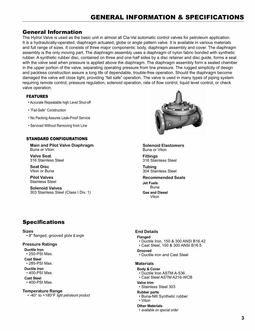
General InformationThe Hytrol Valve is used as the basic unit in almost all Cla-Val automatic control valves for petroleum application. It is a hydraulically-operated, diaphragm actuated, globe or angle pattern valve. It is available in various materials and full range of sizes. It consists of three major components: body, diaphragm assembly and cover. The diaphragm assembly is the only moving part. The diaphragm assembly uses a diaphragm of nylon fabric bonded with synthetic rubber. A synthetic rubber disc, contained on three and one half sides by a disc retainer and disc guide, forms a seal with the valve seat when pressure is applied above the diaphragm. The diaphragm assembly form a sealed chamber in the upper portion of the valve, separating operating pressure from line pressure. The rugged simplicity of design and packless construction assure a long life of dependable, trouble-free operation. Should the diaphragm become damaged the valve will close tight, providing “fail safe” operation. The valve is used in many types of piping system requiring remote control, pressure regulation, solenoid operation, rate of flow control, liquid level control, or check valve operation.
features• Accurate Repeatable high Level Shut-off
• “Fail-Safe” Construction
• No Packing Assures Leak-Proof Service
• Serviced Without Removing from Line
standard confIGuratIonsMain and Pilot Valve DiaphragmBuna or VitonValve Seat316 Stainless SteelSeat DiscViton or BunaPilot ValvesStainless SteelSolenoid Valves303 Stainless Steel (Class I Div. 1)
Solenoid ElastomersBuna or VitonFittings316 Stainless SteelTubing304 Stainless SteelRecommended SealsJet Fuels BunaGas and Diesel Viton
SpecificationsSizes
• 8" flanged, grooved globe & angle
Pressure RatingsDuctile Iron • 250-PSI Max.
Cast Steel • 285-PSI Max.
Ductile Iron • 400-PSI Max.
Cast Steel • 400-PSI Max.
Temperature Range • -40° to +180°F light petroleum product
End DetailsFlanged• Ductile Iron, 150 & 300 ANSI B16.42• Cast Steel, 150 & 300 ANSI B16.5
Grooved• Ductile iron and Cast Steel
MaterialsBody & Cover• Ductile Iron ASTM A-536• Cast Steel ASTM A216-WCB
Valve trim• Stainless Steel 303
Rubber parts• Buna-N® Synthetic rubber• Viton
Other Materials• available on special order
3

dIMensIons & shIPPInG WeIGhts
cV factorCV Factor is defined as the number of gallons per minute of water at 60°F which will flow at a one pound per square inch differential.
Valve Dimensions
Estimated Shipping Weights And Dimensions for cast steel and ductile valves
Globe style ValVe anGle style ValVe
Q = flow rate (GPM)Cv = flow coefficientG = specific gravity∆P = pressure drop (psi)
Cv
(G/∆P)½ Q =
Valve size Weight lbs. Dimensions Inches 2” 60 15 x 19 x 20 3” 95 15 x 19 x 20 4” 170 19 x 19 x 22 6” 305 24 x 24 x 26 8” 670 31 x 28 x 30
Valve sizeDimensions 2" 3" 4" 6" 8"A: 150 ANSI 9.38 12.00 15.00 20.00 25.38AA:300 ANSI 10.00 13.25 15.62 21.00 26.38B: Diameter 6.62 9.12 11.50 15.75 20.00C: Max. 6.50 8.19 10.62 13.38 16.00D: 1.50 2.56 3.19 4.31 5.31E: 150 ANSI 4.75 6.00 7.50 10.00 12.75EE: 300 ANSI 5.00 6.38 7.88 10.50 13.25F: 150 ANSI 3.25 4.00 5.00 6.00 8.00FF: 300 ANSI 3.50 4.38 5.31 6.50 8.50
Valve Size 2" 3" 4" 6" 8" 100-34 Globe Pattern 49 107 200 440 771100-34 Angle Pattern 62 137
4
PIlot oPerated solenoId controls ValVes
3
2A 2B
3A 3B
9A 9B
8
7
1
5
6
4
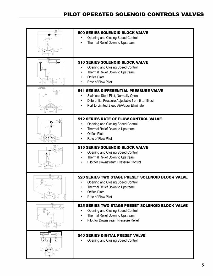
500 SErIES SolEnoID BloCk VAlVE• Opening and Closing Speed Control• Thermal Relief Down to Upstream
510 SErIES SolEnoID BloCk VAlVE• Opening and Closing Speed Control• Thermal Relief Down to Upstream• Orifice Plate• Rate of Flow Pilot
511 serIes dIfferentIal Pressure ValVe• Stainless Steel Pilot, Normally Open• Differential Pressure Adjustable from 5 to 16 psi.• Port to Limited Bleed Air/Vapor Eliminator
512 serIes rate of floW control ValVe• Opening and Closing Speed Control• Thermal Relief Down to Upstream• Orifice Plate• Rate of Flow Pilot
515 SErIES SolEnoID BloCk VAlVE• Opening and Closing Speed Control• Thermal Relief Down to Upstream• Pilot for Downstream Pressure Control
520 SErIES TWo STAGE PrESET SolEnoID BloCk VAlVE• Opening and Closing Speed Control• Thermal Relief Down to Upstream• Orifice Plate• Rate of Flow Pilot
525 SErIES TWo STAGE PrESET SolEnoID BloCk VAlVE• Opening and Closing Speed Control• Thermal Relief Down to Upstream• Pilot for Downstream Pressure Relief
540 SErIES DIGITAl PrESET VAlVE• Opening and Closing Speed Control
5
PrIncIPles of oPeratIon & InstallatIon GuIdelInes
BRIDGEWALL INDICATOR(cast into side of valve body)
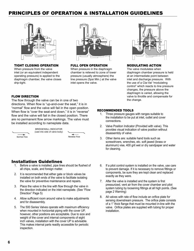
floW dIrectIonThe flow through the valve can be in one of two directions. When flow is “up-and-over the seat,” it is in “normal” flow and the valve will fail in the open position. When flow is “over the seat-and down,” it is in “reverse” flow and the valve will fail in the closed position. There are no permanent flow arrow markings. The valve must be installed according to nameplate data.
tIGht closInG oPeratIonWhen pressure from the valve inlet (or an equivalent independent operating pressure) is applied to the diaphragm chamber, the valve closes drip-tight.
full oPen oPeratIonWhen pressure in the diaphragm chamber is relieved to zone of lower pressure (usually atmosphere) the line pressure (5psi Min.) at the valve inlet opens the valve.
ModulatInG actIonThe valve modulates when diaphragm chamber pressure is held at an intermediate point between inlet and discharge pressure. With the use of a Cla-Val “modulating control” which reacts to line pressure changes, the pressure above the diaphragm is varied, allowing the valve to throttle and compensate for the change.
recoMMended tools1. Three pressure gauges with ranges suitable to
the installation to be put at inlet, outlet and cover connections.
2. Valve Position Indicator (Provided with valve). This provides visual indication of valve position without disassembly of valve.
3. Other items are: suitable hand tools such as screwdrivers, wrenches, etc. soft jawed (brass or aluminum) vise, 400 grit wet or dry sandpaper and water for cleaning.
Installation Guidelines1. Before a valve is installed, pipe lines should be flushed of
all chips, scale, and foreign matter.2. It is recommended that either gate or block valves be
installed on both ends of the valve to facilitate isolating the valve for preventive maintenance and repairs.
3. Place the valve in the line with flow through the valve in the direction indicated on the inlet nameplate. (See “Flow Direction” Page 5)
4. Allow sufficient room around valve to make adjustments and for disassembly.
5. The 500 Series Valves operate with maximum efficiency when mounted in horizontal piping with the cover UP, however, other positions are acceptable. Due to size and weight of the cover and internal components of eight inch valves, installation with the cover UP is advisable. This makes internal parts readily accessible for periodic inspection.
6. If a pilot control system is installed on the valve, use care to prevent damage. If it is necessary to remove fittings or components, be sure they are kept clean and replaced exactly as they were.
7. After the valve is installed and the system is first pressurized, vent air from the cover chamber and pilot system tubing by loosening fittings at all high points. (See page 2 Warning)
8. All valves with rate of flow include an orifice plate for sensing downstream pressure. The orifice plate consists of a 1” thick flange that must be mounted in-line with the valve. Orifice plates are supplied with tubing for proper installation.
6

troubleshootInG
Care should be taken when doing the troubleshooting checks on the valve. These checks do require the valve to open fully. This will either allow a high flow rate through the valve, or the downstream pressure will quickly increase to the inlet pressure. In some cases, this can be very harmful. Where this is the case, and there are no block valves in the system to protect the downstream piping, it should be realized that the valve cannot be serviced under pressure. Steps should be taken to remedy this situation before proceeding any further. (See Warning page 2)
! cautIon
The following troubleshooting guide assumes that all other components of the pilot control system have been checked out and are in proper working condition. (See appropriate sections in Technical Manual for complete valve).All troubleshooting is possible without removing the valve from the line or removing the cover. It is highly recommended to permanently install a Valve Position Indicator (Provided with valve) and three gauges in unused Hytrol inlet, outlet and cover connections.
Three ChecksThe Valve has only one moving part (the diaphragm and disc assembly). So, there are only three major types of problems to consider.Diaphragm: Valve is stuck; the diaphragm assembly is not free to move through a full stroke either from open to close or vice versa.
Freedom of Movement: Valve is free to move and can’t close because of a worn out diaphragm.
Tight Sealing: Valve leaks even though it is free to move and the diaphragm isn’t leaking.
ProbleM Probable cause solutIonFails to Close 1. Closed isolation valves in control system, or in
main line.1. Open Isolation valves.
1. Lack of cover chamber pressure. 1. Check upstream pressure, pilot system, strainer, tubing, valves, or needle valves for obstruction.
1. Diaphragm damaged. Diaphragm Check pg 7 1. Replace diaphragm.1. Diaphragm assembly inoperative. 1. Clean and polish stem. Inspect and replace any
damaged or badly eroded parts.2. Corrosion or excessive scale build up on valve stem. Freedom of Movement Check pg 7
1. Mechanical obstruction. Object lodged in valve. Freedom of Movement Check pg 7
1. Remove obstruction.
1. Worn disc. Tight Seating Check pg 8 1. Replace disc.1. Badly scored seat Tight Seating Check pg 8 1. Replace seat.
Fails to Open 1. Closed upstream and/or downstream isolation valves in main line.
1. Open Isolation valves.
1. Insufficient line pressure. 1. Check upstream pressure (Minimum 5psi flowing line pressure differential).
1. Diaphragm assembly inoperative. Corrosion or excessive buildup on valve stem. Freedom of Movement Check pg 7
1. Clean and polish stem. Inspect and replace any damaged or badly eroded parts.
1. Diaphragm damaged. (For valves in "reverse flow" only.
1. Replace diaphragm.
7
DIAPhrAGM ChECk1. Shut off pressure to the valve by slowly closing upstream
and downstream isolation valves. (SEE CAUTION - page 6).
2. Disconnect or close all pilot control lines to the valve cover and leave only one fitting in highest point of cover open to atmosphere.
troubleshootInG
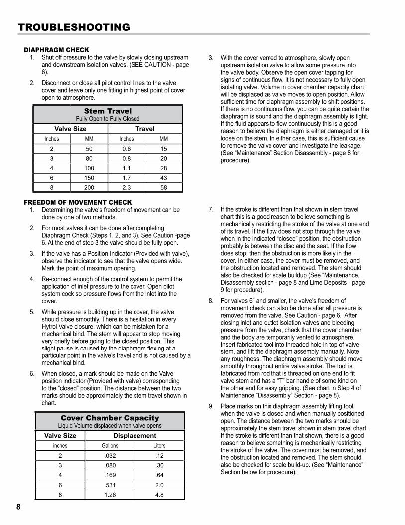
Cover Chamber CapacityLiquid Volume displaced when valve opens
Valve Size Displacementinches Gallons Liters
2 .032 .123 .080 .304 .169 .64
6 .531 2.08 1.26 4.8
Stem TravelFully Open to Fully Closed
Valve Size TravelInches MM Inches MM
2 50 0.6 153 80 0.8 204 100 1.1 28
6 150 1.7 438 200 2.3 58
3. With the cover vented to atmosphere, slowly open upstream isolation valve to allow some pressure into the valve body. Observe the open cover tapping for signs of continuous flow. It is not necessary to fully open isolating valve. Volume in cover chamber capacity chart will be displaced as valve moves to open position. Allow sufficient time for diaphragm assembly to shift positions. If there is no continuous flow, you can be quite certain the diaphragm is sound and the diaphragm assembly is tight. If the fluid appears to flow continuously this is a good reason to believe the diaphragm is either damaged or it is loose on the stem. In either case, this is sufficient cause to remove the valve cover and investigate the leakage. (See “Maintenance” Section Disassembly - page 8 for procedure).
FrEEDoM oF MoVEMEnT ChECk1. Determining the valve’s freedom of movement can be
done by one of two methods.2. For most valves it can be done after completing
Diaphragm Check (Steps 1, 2, and 3). See Caution -page 6. At the end of step 3 the valve should be fully open.
3. If the valve has a Position Indicator (Provided with valve), observe the indicator to see that the valve opens wide. Mark the point of maximum opening.
4. Re-connect enough of the control system to permit the application of inlet pressure to the cover. Open pilot system cock so pressure flows from the inlet into the cover.
5. While pressure is building up in the cover, the valve should close smoothly. There is a hesitation in every Hytrol Valve closure, which can be mistaken for a mechanical bind. The stem will appear to stop moving very briefly before going to the closed position. This slight pause is caused by the diaphragm flexing at a particular point in the valve’s travel and is not caused by a mechanical bind.
6. When closed, a mark should be made on the Valve position indicator (Provided with valve) corresponding to the “closed” position. The distance between the two marks should be approximately the stem travel shown in chart.
7. If the stroke is different than that shown in stem travel chart this is a good reason to believe something is mechanically restricting the stroke of the valve at one end of its travel. If the flow does not stop through the valve when in the indicated “closed” position, the obstruction probably is between the disc and the seat. If the flow does stop, then the obstruction is more likely in the cover. In either case, the cover must be removed, and the obstruction located and removed. The stem should also be checked for scale buildup (See “Maintenance, Disassembly section - page 8 and Lime Deposits - page 9 for procedure).
8. For valves 6” and smaller, the valve’s freedom of movement check can also be done after all pressure is removed from the valve. See Caution - page 6. After closing inlet and outlet isolation valves and bleeding pressure from the valve, check that the cover chamber and the body are temporarily vented to atmosphere. Insert fabricated tool into threaded hole in top of valve stem, and lift the diaphragm assembly manually. Note any roughness. The diaphragm assembly should move smoothly throughout entire valve stroke. The tool is fabricated from rod that is threaded on one end to fit valve stem and has a “T” bar handle of some kind on the other end for easy gripping. (See chart in Step 4 of Maintenance “Disassembly” Section - page 8).
9. Place marks on this diaphragm assembly lifting tool when the valve is closed and when manually positioned open. The distance between the two marks should be approximately the stem travel shown in stem travel chart. If the stroke is different than that shown, there is a good reason to believe something is mechanically restricting the stroke of the valve. The cover must be removed, and the obstruction located and removed. The stem should also be checked for scale build-up. (See “Maintenance” Section below for procedure).
8
TIGhT SEAlInG ChECk 1. Test 1 & 2 for seat leakage after completing checks #1 & #2 (Steps 1 to 12). See Caution - page 6. Close the isolation valve
downstream of the valve. Apply inlet pressure to the cover of the valve, wait until it closes. Install an outside source pressure gauge between the two closed valves using one of the two ports in the outlet side of the valve. Watch the pressure gage. If the pressure begins to climb, then either the downstream isolation valve is permitting pressure to creep back, or the valve is allowing pressure to go through it. Usually the pressure at the valve inlet will be higher than on the isolation valve discharge, so if the pressure goes up to the inlet pressure, you can be sure the Hytrol is leaking. Install another gauge downstream of isolating valve. If the pressure between the valves only goes up to the pressure on the isolation valve discharge, the valve is holding tight, and it was just the isolation valve leaking.
MaintenancePreVentatIVe MaIntenanceThe valve requires no lubrication or packing and a minimum of maintenance. However, a periodic inspection schedule should be established to determine how the operating conditions of the system are affecting the valve. The effect of these actions must be determined by inspection.dIsasseMblyInspection or maintenance can be accomplished without removing the valve from the line. Repair kits with new diaphragm and disc are recommended to be on hand before work begins.
To disassemble a valve:1. Close upstream and downstream isolation valves and
independent operating pressure when used to shut off all pressure to the valve.
2. Loosen tube fittings in the pilot system to remove pressure from valve body and cover chamber. After pressure has been released from the valve, use care to remove the controls and tubing. Note and sketch position of tubing and controls for reassembly. The schematic in front of the Technical Manual (separately supplied) can be used as a guide when reassembling pilot system.
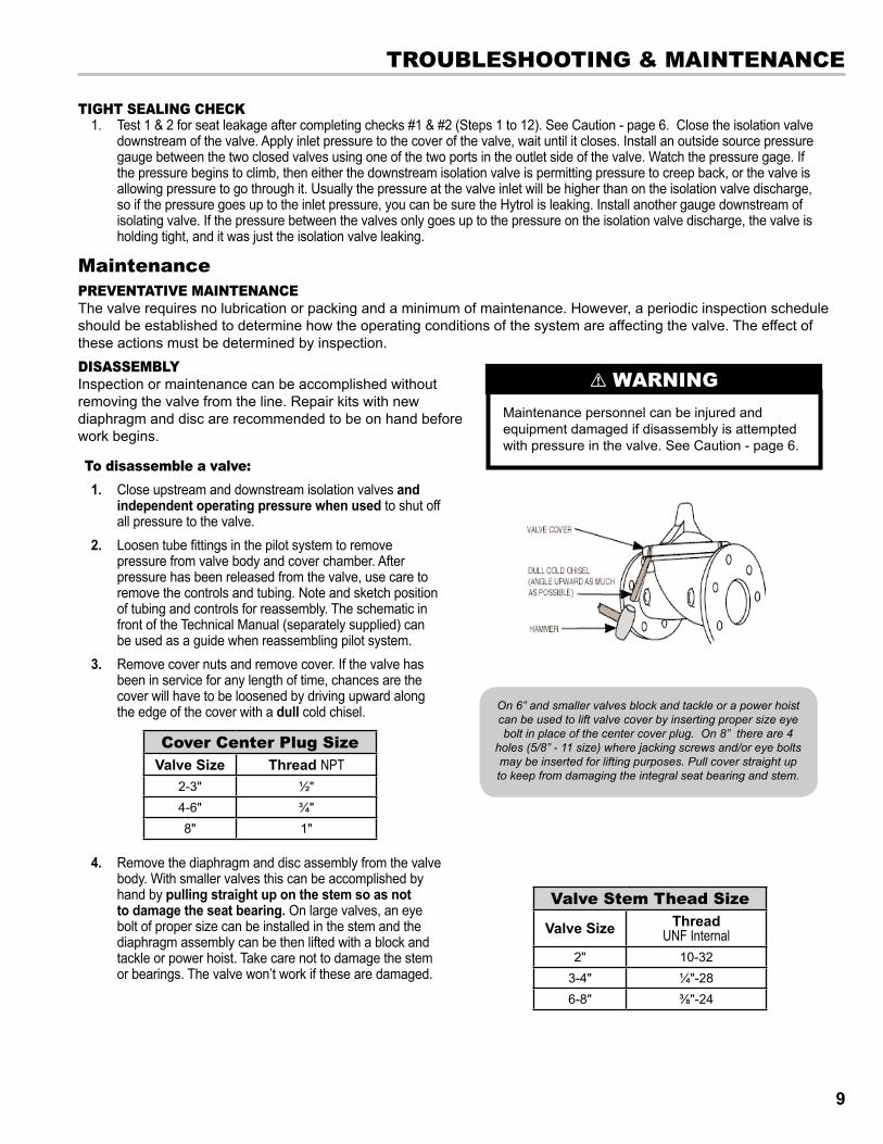
3. Remove cover nuts and remove cover. If the valve has been in service for any length of time, chances are the cover will have to be loosened by driving upward along the edge of the cover with a dull cold chisel.
4. Remove the diaphragm and disc assembly from the valve body. With smaller valves this can be accomplished by hand by pulling straight up on the stem so as not to damage the seat bearing. On large valves, an eye bolt of proper size can be installed in the stem and the diaphragm assembly can be then lifted with a block and tackle or power hoist. Take care not to damage the stem or bearings. The valve won’t work if these are damaged.
troubleshootInG & MaIntenance
Maintenance personnel can be injured and equipment damaged if disassembly is attempted with pressure in the valve. See Caution - page 6.
! WarnInG
Cover Center Plug SizeValve Size Thread NPT
2-3" ½"4-6" ¾"8" 1"
Valve Stem Thead Size
Valve Size Thread UNF Internal
2" 10-323-4" ¼"-286-8" ⅜"-24
On 6” and smaller valves block and tackle or a power hoist can be used to lift valve cover by inserting proper size eye bolt in place of the center cover plug. On 8” there are 4
holes (5/8” - 11 size) where jacking screws and/or eye bolts may be inserted for lifting purposes. Pull cover straight up to keep from damaging the integral seat bearing and stem.
9
Maintenance DISASSEMBly (ConT’D)
5. The next item to remove is the stem nut. Examine the stem threads above the nut for signs of mineral deposits or corrosion. If the threads are not clean, use a wire brush to remove as much of the residue as possible. Attach a good fitting wrench to the nut and give it a sharp “rap” rather than a steady pull. Usually several blows are sufficient to loosen the nut for further removal. On the smaller valves, the entire diaphragm assembly can be held by the stem in a vise equipped with soft brass jaws before removing the stem nut.
6. After the stem nut has been removed, the diaphragm assembly breaks down into its component parts. Removal of the disc from the disc retainer can be a problem if the valve has been in service for a long time. Using two screwdrivers inserted along the outside edge of the disc usually will accomplish its removal. Care should be taken to preserve the spacer washers in water, particularly if no new ones are available for re-assembly.
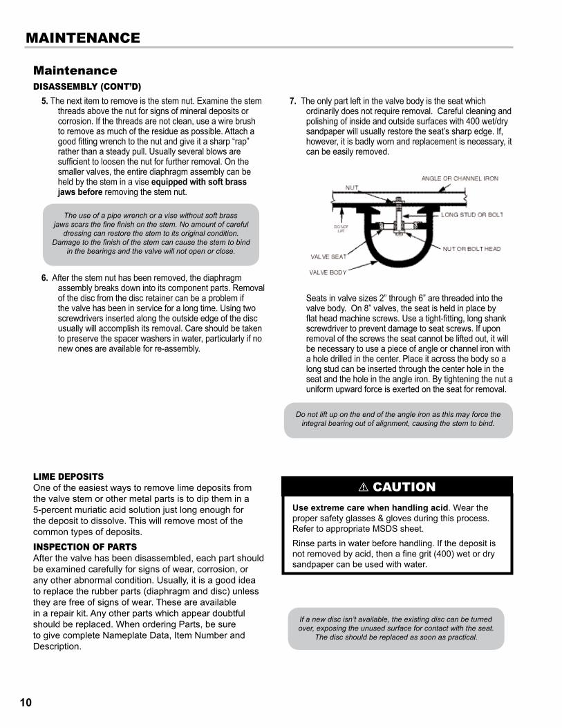
7. The only part left in the valve body is the seat which ordinarily does not require removal. Careful cleaning and polishing of inside and outside surfaces with 400 wet/dry sandpaper will usually restore the seat’s sharp edge. If, however, it is badly worn and replacement is necessary, it can be easily removed.
Seats in valve sizes 2” through 6” are threaded into the valve body. On 8” valves, the seat is held in place by flat head machine screws. Use a tight-fitting, long shank screwdriver to prevent damage to seat screws. If upon removal of the screws the seat cannot be lifted out, it will be necessary to use a piece of angle or channel iron with a hole drilled in the center. Place it across the body so a long stud can be inserted through the center hole in the seat and the hole in the angle iron. By tightening the nut a uniform upward force is exerted on the seat for removal.
MaIntenance
Do not lift up on the end of the angle iron as this may force the integral bearing out of alignment, causing the stem to bind.
The use of a pipe wrench or a vise without soft brass jaws scars the fine finish on the stem. No amount of careful
dressing can restore the stem to its original condition. Damage to the finish of the stem can cause the stem to bind
in the bearings and the valve will not open or close.
If a new disc isn’t available, the existing disc can be turned over, exposing the unused surface for contact with the seat.
The disc should be replaced as soon as practical.
Use extreme care when handling acid. Wear the proper safety glasses & gloves during this process. Refer to appropriate MSDS sheet.
Rinse parts in water before handling. If the deposit is not removed by acid, then a fine grit (400) wet or dry sandpaper can be used with water.
! cautIonlIMe dePosItsOne of the easiest ways to remove lime deposits from the valve stem or other metal parts is to dip them in a 5-percent muriatic acid solution just long enough for the deposit to dissolve. This will remove most of the common types of deposits. InsPectIon of PartsAfter the valve has been disassembled, each part should be examined carefully for signs of wear, corrosion, or any other abnormal condition. Usually, it is a good idea to replace the rubber parts (diaphragm and disc) unless they are free of signs of wear. These are available in a repair kit. Any other parts which appear doubtful should be replaced. When ordering Parts, be sure to give complete Nameplate Data, Item Number and Description.
10
MaintenancereasseMbly
1. Reassembly is the reverse of the disassembly procedure - refer to page 8. If a new disc has been installed, it may require a different number of spacer washers to obtain the right amount of “grip” on the disc. When the diaphragm assembly has been tightened to a point where the diaphragm cannot be twisted, the disc should be compressed very slightly by the disc guide. Excessive compression should be avoided. Use just enough spacer washers to hold the disc firmly without noticeable compression.
2. Make Sure the Stem Nut is Very Tight. Attach a proper wrench to the nut and give it a sharp “rap” rather than a steady pull. Usually several blows are sufficient to tighten the stem nut for final tightening. Failure to do so could allow the diaphragm to pull loose and tear when subjected to pressure.
MaIntenance & test Procedure
3. Carefully install the diaphragm assembly by lowering the stem through the seat bearing. Take care not to damage the stem or bearing. Line up the diaphragm holes with the stud or bolt holes on the body. On large valves with studs, it may be necessary to hold the diaphragm assembly up part way while putting the diaphragm over the studs.
4. Put spring in place and replace cover. Make sure diaphragm is lying smooth under the cover.
5. Tighten cover nuts firmly using a cross-over pattern until all nuts are tight.
6. Test Hytrol Valve before re-installing pilot valve system.
Test Procedure After Valve AssemblyThere are a few simple tests which can be made in the field to make sure the valve has been assembled properly. Do these before installing pilot system and returning valve to service. These are similar to the three troubleshooting tests.
1. Check the diaphragm assembly for freedom of movement after all pressure is removed from the valve. See caution - page 6. Insert fabricated tool into threaded hole in top of valve stem, and lift the diaphragm assembly manually. Note any roughness, sticking or grabbing. The diaphragm assembly should move smoothly throughout entire valve stroke. The tool is fabricated from rod that is threaded on one end to fit valve stem (See chart in Step 4 of “Disassembly” section - page 8) and has a “T” Bar handle of some kind on the other end for easy gripping.
Place marks on this diaphragm assembly lifting tool when the valve is closed and when manually positioned open. The distance between the two marks should be approximately the stem travel shown in stem travel chart. (See “Freedom of Movement Check” section - page 7) If the stroke is different than that shown, there is a good reason to believe something is mechanically restricting the stroke of the valve. The cover must be removed, the obstruction located and removed. (See “Maintenance” Section - page 8 for procedure).
Due to the weight of the diaphragm assembly this procedure is not possible on valves 8” and larger. On these valves, the same determination can be made by carefully introducing a low pressure-less than five psi into the valve body with the cover vented. See Caution - page 6. Looking in cover center hole see the diaphragm assembly lift easily without hesitation, and then settle back easily when the pressure is removed.
2. To check the valve for drip-tight closure, a line should be connected from the inlet to the cover, and pressure applied at the inlet of the valve. If properly assembled, the valve should hold tight with as low as ten PSI at the inlet. (See “Trouble Shooting” section -page 8) - (Check #3 - Tight Sealing Check).
3. With the line connected from the inlet to the cover, apply full working pressure to the inlet. Check all around the cover for any leaks. Re-tighten cover nuts if necessary to stop leaks past the diaphragm.
4. Remove pressure, then re-install the pilot system and tubing exactly as it was prior to removal. Bleed air from all high points. See Caution - page 6.
5. Follow steps under the manual provided with the valve for returning complete valve back to service.
11
© 2007 Liquid ControlsPub. No. 500374
(6/13)
105 Albrecht DriveLake Bluff, IL 60044-22421.800.458.5262 • 847.295.1050Fax: 847.295.1057www.lcmeter.com
TopTech SySTemS1124 Florida Central ParkwayLongwood, FL 32750(407) 332-1774
Nateus Business ParkNieuwe Weg 1-Haven 1053B-2070 Zwijndrecht (Antwerp), Belguim+32 (0)3 250 60 60
Liquid conTroLS105 Albrecht DriveLake Bluff, IL 60044(847) 295-1050
SAmpiVia Amerigo Vespucci 155011 Altopascio (Lucca), Italy+39 0583 24751
ideX FLuid And meTering pvT. LTd.Survey No. 256, AlindraSavli GIDC, ManjusarDist. Vadodara 391 770Gujarat, India+91 265 2631855
FAure hermAnRoute de Bonnetable B.P. 2015472406 La Ferté-Bernard Cedex, France+33 (0)2 43 60 28 60
4720 North Sam Houston Parkway WestSuite 100Houston, TX 77086
corken3805 Northwest 36th St.Oklahoma City, OK 73112(405) 946-5576