mobile satellite internet controller use with all motosat internet satellite antenna mounts. the...
TRANSCRIPT

D3
Mobile Satellite Internet Controller
Operation and Configuration Manual
Firmware Version 3.9.1 901-D3-OM-391 June 21, 2007

2
The DataStorm D3 Satellite Internet Controller
Don’t let the Simple Design and Connectivity fool you! The MotoSAT DataStorm D3 Controller is one of the most advanced Satellite Antenna Controllers available. Simple to Configure, Simple to Operate. The MotoSAT DataStorm D3 Controller is a Satellite Internet Antenna Positioner with advanced features that allow the user the flexibility they need to operate any Satellite Internet System in any worldwide environment. The D3 Controller is designed to be a “Stand Alone” Satellite Antenna Controller for use with all MotoSAT Internet Satellite Antenna Mounts. The MotoSAT D3 can Locate, Peak, and Cross Pol a MotoSAT Antenna Mount with no connection to a router, Computer, or Satellite Modem. The D3 connects to a MotoSAT Antenna using one Cable (9wires) and 2 RG6 Cables. Even though the D3 can be configured for extremely complex requirements it is simple to operate. The D3 can be accessed through a standard HTML viewer or set up to operate from the three button front panel. The D3 Controller is approved by many satellite network providers to perform stand alone cross pols without NMC or NOC intervention. The D3 Mobile Satellite Internet Controller is designed to allow the user the worlds most “Advanced Simple Interface”. After the D3 has been properly wired to a DataStorm Mount and connected properly to a LAN Switch or router this controller will be ready to configure and operate. Features Front Panel Search, Stow, and Power Commands LED (Status Indicators) TCP/IP-LAN Interface HTML Configuration and Operation Pages Telnet Commands for Diagnostics No Software Required on PC True DVB Satellite Identification Field Firmware Upgradeable Simple Electrical Connections

3
This is a preliminary document containing current information for the D3 using Firmware Version 3.9.1
D3 Table of Contents
Front Panel ………………………….. 4 Rear Panel ………………………….. 5 Operation …………………………… 6 Wiring ……………………………….. 9
• D3 Wiring Diagram
• System Wiring Initial Setup ………………………… 11 Configurations …………………….. 17 Firmware Upgrade …………………. 29 Setting Isolation (TX Offset) ……… 36 Troubleshooting …………………… 37
• Telnet Commands …………… 37

4
D3 Front Panel
The Front Panel has three switches, Power, Search, and Stow. The Power Button is used to turn the D3 Controller On and Off. When Powered on the Green LED to the Left of the Power Button will illuminate. The Search Button will cause the dish to raise from the stowed position and search for the configured Satellite. Usually the LNB, LAN and GPS Lights need to be illuminated before a “Search” will begin. The Ready and Busy LEDs will blink during search. The Stow Button when selected will Stow the Dish to the Travel Position. When the Dish is stowing the Busy and Stow Light will Blink. When Dish is Stowed the Stow Light will be on Solid. Power Light (Green) is illuminated when ever the D3 is powered on. LNB Light (Blue) will illuminate when a Modem is connected to the D3 and power is applied to the Modem. If the D3 is configured to Generic Mode then the LNB LED will illuminate when Search is initiated. LAN Light (Blue) is illuminated when a network connection is detected. GPS Light (Blue) will illuminate when GPS has detected a valid Latitude and Longitude location. READY Light (Blue) will illuminate when the Target Satellite has peaked and a network connection has been detected. BUSY Light (Red) illuminates under many conditions. Typically when the dish is moving will be the common reason. See Advanced Lights for additional details on all Front Panel LEDs. STOW Light (Red) is on Solid when the Dish is Stowed, and Blinks while the Dish is Stowing. See Advanced Lights for additional functions for all LEDs.
5
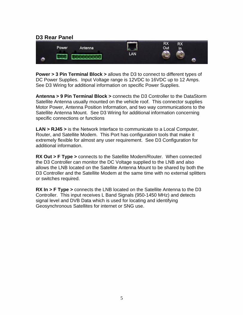
D3 Rear Panel
Power > 3 Pin Terminal Block > allows the D3 to connect to different types of DC Power Supplies. Input Voltage range is 12VDC to 16VDC up to 12 Amps. See D3 Wiring for additional information on specific Power Supplies. Antenna > 9 Pin Terminal Block > connects the D3 Controller to the DataStorm Satellite Antenna usually mounted on the vehicle roof. This connector supplies Motor Power, Antenna Position Information, and two way communications to the Satellite Antenna Mount. See D3 Wiring for additional information concerning specific connections or functions LAN > RJ45 > is the Network Interface to communicate to a Local Computer, Router, and Satellite Modem. This Port has configuration tools that make it extremely flexible for almost any user requirement. See D3 Configuration for additional information. RX Out > F Type > connects to the Satellite Modem/Router. When connected the D3 Controller can monitor the DC Voltage supplied to the LNB and also allows the LNB located on the Satellite Antenna Mount to be shared by both the D3 Controller and the Satellite Modem at the same time with no external splitters or switches required. RX In > F Type > connects the LNB located on the Satellite Antenna to the D3 Controller. This input receives L Band Signals (950-1450 MHz) and detects signal level and DVB Data which is used for locating and identifying Geosynchronous Satellites for internet or SNG use.

6
D3 Normal Operation IMPORTANT! Before the D3 is ready for normal use the system must be wired and configured correctly. Go to D3 Wiring and D3 Configuration for setup. The D3 Controller can be operated through either Front Panel Controls or via the HTML Interface built into the Controller. To use the HTML Interface you must access the D3 by using a standard Web Browser such as Internet Explorer, Netscape, or Mozilla Firefox. Open the Browser as you normally would then type into the address bar the IP Address of the D3 Controller. The default IP address of the D3 is set to 192.168.0.250 but this may/can be changed in the D3 Configuration “Network Settings” to work with any router/network configuration.

7
Find Satellite (Search) Note: Before the System will begin a search the LNB, LAN, and GPS lights
should be illuminated. Using either the Search Command on the HTML System Status Page or the Search Button on the Front Panel of the D3 Controller will initiate a search for the Target Satellite. The System will begin to search and the D3 Front Panel will show Ready and Busy Lights flashing. The HTML Status Screen will show current status. The Target Satellite is the Satellite that was configured in the D3
Configuration Satellite Longitude. The Longitude of the Satellite you want to locate is represented by a numerical value from 0 to 180 followed by an E or W for the correct Hemisphere.
When initiated the DataStorm Mount will move elevation to a calculated elevation position, perform a tilt sensor adjustment by moving azimuth 180 degrees then return azimuth to zero, adjust the Skew to the calculated Skew Angle, then begin an Azimuth Search of the sky looking for any valid satellite. Once any satellite is located the D3 will attempt to identify this satellite by testing the DVB data. If the data matches the Target Satellite then the system will begin a final peaking routine. If the data matches a different satellite then this becomes the Reference Satellite and the location of the Target Satellite is calculated and the DataStorm Mount will move to the correct location. Once the Target Satellite is located the D3 Controller will perform a final peak and then adjust skew for Final Isolation Peak. When finished the D3 Controller will show the Ready Light on. The HTML Screen will show Search Operation Complete. The System Modem should be ready for use. Operation complete. Stow Dish (Stow) Stowing the Dish puts the antenna back into a travel position where the Antenna is in a Face Down position on the roof of the vehicle pointing toward the rear of the vehicle. To Stow the dish use either the Stow Command on the HTML System Status Page or the Stow Button on the Front Panel of the D3 Controller.

8
The System will begin to stow and the D3 Front Panel will show Stow and Busy Lights flashing. The HTML Status Screen will show Stowing Dish. The typical stow routine will cause the antenna to first move elevation to a full back position, then rotate Skew fully clockwise (when behind the RF Assembly facing the dish), then rotate Azimuth fully counterclockwise, and finish stowing Elevation to a full down position. When stowed the D3 Controller (powered On) will show the Stow Light on. The HTML Screen will show Stow Dish Operation Complete. When the dish is “Stowed” it is recommended the D3 Controller is powered Off while traveling. Power The Power function is only available on the front panel of the D3. The D3 Controller can not be powered on thru the HTML screen. When Power to the D3 is ON, the Search and Stow Buttons are operational. The HTML Screens are only available when the D3 Power is On. When Power is ON the Green LED to the left of the Power Button is illuminated. It is recommended that when the D3 is not in use and the Dish is Stowed that the D3 Controller be left in the Off Mode. End of D3 Normal Operation

9
D3 Wiring Diagram
DataStorm D3 Wiring Diagram
10
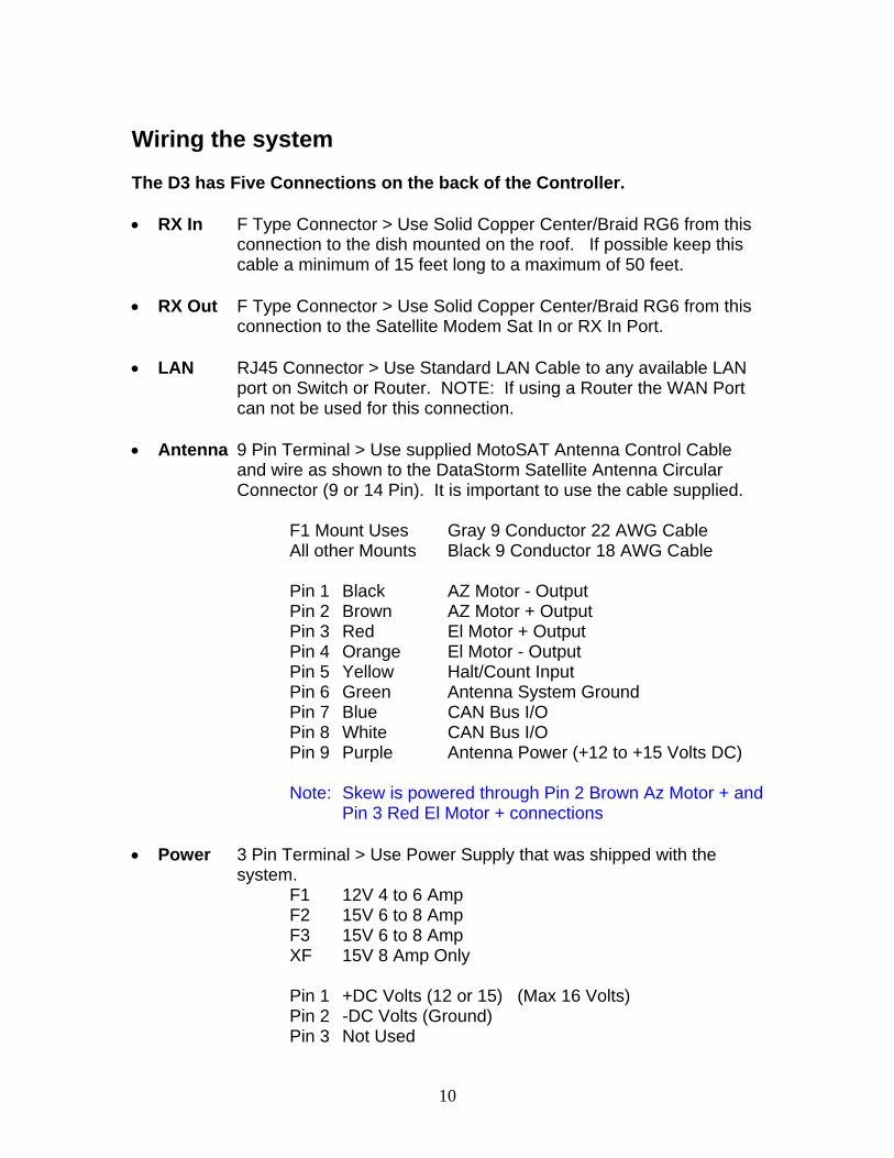
Wiring the system The D3 has Five Connections on the back of the Controller. • RX In F Type Connector > Use Solid Copper Center/Braid RG6 from this
connection to the dish mounted on the roof. If possible keep this cable a minimum of 15 feet long to a maximum of 50 feet.
• RX Out F Type Connector > Use Solid Copper Center/Braid RG6 from this
connection to the Satellite Modem Sat In or RX In Port.
• LAN RJ45 Connector > Use Standard LAN Cable to any available LAN port on Switch or Router. NOTE: If using a Router the WAN Port can not be used for this connection.
• Antenna 9 Pin Terminal > Use supplied MotoSAT Antenna Control Cable
and wire as shown to the DataStorm Satellite Antenna Circular Connector (9 or 14 Pin). It is important to use the cable supplied.
F1 Mount Uses Gray 9 Conductor 22 AWG Cable All other Mounts Black 9 Conductor 18 AWG Cable Pin 1 Black AZ Motor - Output Pin 2 Brown AZ Motor + Output Pin 3 Red El Motor + Output Pin 4 Orange El Motor - Output Pin 5 Yellow Halt/Count Input Pin 6 Green Antenna System Ground Pin 7 Blue CAN Bus I/O Pin 8 White CAN Bus I/O Pin 9 Purple Antenna Power (+12 to +15 Volts DC)
Note: Skew is powered through Pin 2 Brown Az Motor + and
Pin 3 Red El Motor + connections • Power 3 Pin Terminal > Use Power Supply that was shipped with the
system. F1 12V 4 to 6 Amp F2 15V 6 to 8 Amp F3 15V 6 to 8 Amp XF 15V 8 Amp Only Pin 1 +DC Volts (12 or 15) (Max 16 Volts) Pin 2 -DC Volts (Ground) Pin 3 Not Used

11
Do not connect the Power Supply to the D3 Controller until all other connections are completed.
MotoSAT DataStorm Satellite Antenna
Wire the Antenna Control Cable and RX connections as described in the D3 Controller wiring above. The TX (F Type Connector) port must be wired directly to the Satellite Modem using Solid Copper Center/Braid RG6. It is recommended that this cable be 15 to 50 Feet whenever possible. A longer cable may affect the performance of the Modem due to power loss through the extend cable length.
Ethernet Router and Satellite Modem
Use DataStorm D3 Wiring Diagram (page 9) as an example of a typical configuration.
For more detail in wiring the Router and Modem see the Installation Manuals supplied with these components. You may also go to www.motosat.com for several common configurations used by our customers. MotoSAT is not responsible for the accuracy or performance of these configurations and you should consult a Networking Professional for assistance in setting these components properly.
After Completing Wiring…
Using the Manuals supplied with the Switch/Router and Satellite Modem, configure these items as directed.
D3 Configuration Connection and Configuration! Nearly 95% of all technical support calls are due to either improper wiring, or incorrect configurations. Please be sure to review these two items before contacting technical support for assistance. The D3 must be configured properly before it can be used in normal operation. Before proceeding insure that all wiring to the D3 Controller is correct. This would include any connections to the DataStorm Mount. See DataStorm D3 Wiring Diagram (page 9).

12
Verify proper Power Supply Note: Check to see that you are using the correct power supply for the model of
DataStorm Mount. F1 12 Volt 4-6 Amp F2 15 Volt 6-8 Amp F3 15 Volt 6-8 Amp XF2 15 Volt 8 Amp XF3 15 Volt 8 Amp First Steps; Proceed only if all wiring to the D3, Computer, router/switch, and mount has been completed and checked. The computer must configured properly to allow communications with the D3 IP address of 192.168.0.250 to complete the D3 setup and configuration. D3 Version 3.9.1 requires performing an initial NVClear and Test Dish before configuring the D3 Controller. Even if your system has Version 3.9.1 installed if this is a new install it must be done.
• Press Search and Stow Buttons at the same time on the front of D3 Controller and then press Power until all LEDs on Front Panel Illuminate. This is known as Boot Mode.
• Open Telnet Session (192.168.0.250) Screenshot 1
• Type nvclear after D2Boot Prompt Note: Case sensitive. D2Boot % or D3Boot % may appear either display is acceptable.

13
Screenshot 2
• This will clear all user configurations to factory default. Always recommended on new installs.
Screenshot 3
• Turn off power to the D3 Controller, and then re-apply power. The Green LED Power indicator to the Left of the Power Button will illuminate.
• Open Web Browser i.e. Internet Explorer to access the D3 HTML Status Page.
• The D3 default page address after an NVClear is always 192.168.0.250, enter this address into the Browser. The following page should appear if the Computer and Router are configured properly.

14
Screenshot 4
• In the Blue Field on the left side of this page under Standard Functions click on Configuration. This will send you to the D3 Configuration Page.
The Screen below only shows the top part of the Configuration Screen. This is the area we are going to set the communications between the D3, Router or Switch, and Modem. It is important that these are configured properly or the system will not work.
• For more information on how to set the (Network Configurations), Local Address, Subnet Mask, Modem Gateway, Router Gateway, DNS Address, and Startup Delay go to D3 Configuration Definitions in this Manual

15
• After setting the Network Configurations click on the Update Settings Button to the right of the Screen to save these values.
o Note: If the Local Address is changed then the D3 will reset this
page, and you will now need to open the Browser using the new Local Address i.e. 192.168.1.250. Then re-enter the configuration page to complete the D3 Configuration.
Screenshot 5
• Satellite System, Satellite Longitude, Frequency, RX Polarization, and TX Polarization must be set for the D3 to operate properly. Get these settings from your VAR or ISP provider.

16
• The Satellite System has several options currently available. Use the light blue down arrow to select the correct system type.
• Once these 5 settings are input, click on the Update Settings Button to the
right of the Screen to save these values.
• Symbol Rate (below) currently is only used in HughesNet mode. This value is typically set to 30, but it is important to confirm this value with your ISP.
• LO Frequency (below) is typically set to 10750 MHz. Most Continental US
Satellites use this LO in their LNB’s. Only change this value if the LNB LO Frequency is different.
• For all other configuration settings go to D3 Configuration Definitions in
this Manual for additional information. Screenshot 6
17
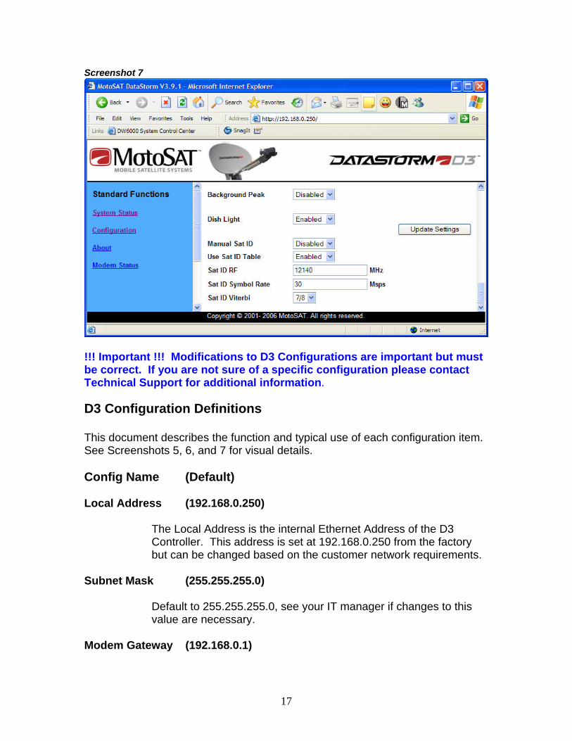
Screenshot 7
!!! Important !!! Modifications to D3 Configurations are important but must be correct. If you are not sure of a specific configuration please contact Technical Support for additional information. D3 Configuration Definitions This document describes the function and typical use of each configuration item. See Screenshots 5, 6, and 7 for visual details. Config Name (Default) Local Address (192.168.0.250)
The Local Address is the internal Ethernet Address of the D3 Controller. This address is set at 192.168.0.250 from the factory but can be changed based on the customer network requirements.
Subnet Mask (255.255.255.0)
Default to 255.255.255.0, see your IT manager if changes to this value are necessary.
Modem Gateway (192.168.0.1)
18
This value is set to the modem address. See Modem manual for more information.
Router Gateway (192.168.0.1)
This value is set to the Router address. If a LAN switch is used then setting this to the modem address is typical. See Router or Modem manuals for more information.
DNS Address (192.168.0.1)
This value is set to the modem address. See manuals or white papers for more information.
Startup Delay ( 0 )
Startup Delay sets a time delay from D3 Power On to active LAN connection. This time period is displayed in seconds (0 to 999). This time delay is used to allow the Router and or Modem time to configure properly and communicate after AC power has been applied to these devices. The D3 will attempt to communicate with the modem after the delay time has expired. Example; a Linksys router typically requires 20 seconds before it has set DHCP and accessed the WAN port before it is ready. So setting the Startup Delay to 30 seconds should resolve this for the D3 to see the modem. Network Switches do not require a delay.
Satellite System (Generic)
Satellite System sets Modem or ISP type. Setting this value for the proper modem type will allow the D3 to integrate at different levels with specific modems. Currently the D3 integrates closely with the HughesNet and iDirect Modems allowing the D3 to confirm correct Satellite Identification, Signal Quality level, set TX ranging values, etc. The D3 may soon integrate with other Modem suppliers. Other Modems currently displayed in the Satellite System drop down box are; UnaSAT, Aloha, and Generic. These currently function in Generic mode. Important Note: It is extremely important that when using HughesNet mode that many of the following configurations are set correctly. Just being close will not work.

19
Satellite Longitude (89W)
Satellite Longitude is a numerical value that sets the Target Satellite Location. I.E. 89W If inputting a Satellite Longitude in the western hemisphere then you would place a W after the numerical longitude value. It is not necessary to add the W as the western hemisphere is set to default. If inputting a Satellite Longitude in the eastern hemisphere then you would place a E after the numerical longitude value.
IF Frequency (1430)
HughesNet Required! This value is set from 950 to 1450 MHz. Check with the Hughes configurations to insure accuracy. For all other Modems including Generic this value is not necessary.
RX Polarization (Vertical)
This is a critical setting. For the D3 to set the Satellite System properly for correct modem operation the Receive Polarization must be correct. Contact your ISP for the proper RX Polarization setting.
TX Polarization (Horizontal)
HughesNet Required! Sets the TX Polarization value for Hughes. Not required for all other systems. Check with the Hughes configurations to insure accuracy. Note: When using the DataStorm F1 Mount TX Polarization must be Horizontal Only! When using F2, F3, XF2, and XF3 mounts the TX Polarization must be set to the opposite field of the RX Polarization.
Symbol Rate (30)
HughesNet Required! The symbol rate is entered in Msps (Mega Symbols per Second). Again this value is only needed in HughesNet mode. Example; 30,000,000 symbols per second is entered as 30 Msps.
20
LO Frequency (10750)
LO Frequency is used in the LNB to mix with the incoming RF signal to produce an IF Frequency in the 950 to 2150 MHz range. Check with the Modem supplier to see what IF Frequency is needed for your specific application. The Default LO Frequency is 10750 MHz. This value is usually set between 9750 to 11300 MHz. It is extremely important this value is set correctly for proper D3 operation.
22Khz Tone (Disabled)
The 22Khz Tone can be used to switch the LO Oscillator from one frequency to another. Some Modems may require 22Khz tone for other reasons. Check with your Modem Hardware supplier or ISP to see if 22Khz tone is necessary for your application.
13 Volt Search (Disabled)
The 13 Volt Search locks the LNB Voltage to 13 Volts. Typically the D3 Controller will follow the Modem LNB voltage and output the same DC Voltage Level as the Modem. When 13 Volt Search is Enabled the D3 will continuously output 13Volts until the Search Operation is completed. Usually 13 Volts correlates to Vertical Polarity.
H/V Voltage Invert (Disabled)
The H/V Voltage Invert is used when the LNB on the system is attached to the Feed Assembly in such a way that when 13 Volts supplied to the LNB is actually looking at the Horizontal Receive Field. When this happens the D3 Controller will need this configuration Enabled to operate properly.
Signal Trigger (9)
Signal Trigger is a numerical value that represents a change of Signal Strength Level during a small time period. When this value is triggered the D3 will initiate a Signal Identification Peak. The Signal Trigger Value is set to Default 9. It can be adjusted from 0 to 40. The lower this value can be set the wider view of the sky for a quicker search. If this value is set too low the D3 will begin to stop on false targets such as trees, lights, and buildings. The higher this value is set the narrower the sky view search angle.

21
Dual Verification (Disabled) Dual Verification is used in areas where high RF Reflectivity could cause the D3 to Lock to a mirror image. When Enabled the D3 must verify two satellites in the proper orbital locations before completing the Search Operation. A typical example of this would be when parked close to metal buildings.
Isolation Optimization (Medium)
Isolation Optimization is used to set Cross Polarization (Cross Pol) of the antenna Transmitter to an acceptable Isolation level. Low When set to Low the skew Cross Pol value is determined by calculating the proper skew rotation of the RF Assembly using GPS. If Skew has ever been set to Medium or High mode for initial Cross Pol to Optimize the Isolation then setting Isolation Optimization to low should offer a minimal acceptable isolation for TX use. Medium When set to Medium, Cross Pol is initially set similar to the Low setting. The D3 will then test DVB and Dish Sensors to adjust the DataStorm Mount for optimized Cross Pol. Some initial settings in Skew Offset and TX Offset will need to be adjusted for Medium to function properly. High When set to High, initializes like Medium. When in HughesNet mode the ACP routine will maximize Hughes Isolation to maximum value.
Skew Offset (0)
The D3 Controller use GPS Location to calculate the correct Horizontal and Vertical Skew Angles of a specific satellite based upon the Dish location on earth. However, some Satellites in the Clarke Orbit are Skewed off several degrees from what should be a true H/V based upon their Longitudal position.
22
Your ISP or NOC should provide you with a Skew Offset in this case which you can add as a positive or negative value in Skew Offset. This will correct the initial search skew angle.
Tx Offset (0)
Tx (Transmitter) Offset allows the installer /user the ability to correct the mechanical error of the RF Assembly so when the DataStorm Mount is peaked on Satellite the Transmitter pointing at the Satellite will be properly Cross polled for maximum Isolation. This one time setup requires the system to first be peaked on satellite in Medium Mode. Go to Manual Motor Screen and write down the Skew Count and Degree Values. Call NOC/NMC and perform a Isolation Peaking Test where the NOC steps you through the Skew field and noting when you have hit the maximum Isolation value. Not just a minimum pass value. Read the new Skew Count and Angle values. Add or subtract the difference and place this Angle value in Tx Offset. Note when you repeak the system the Skew Angle Value will display what your original Skew Angle Reading was, but your Skew Count Value will display the new Count Value. See Setting TX Offset (Xpol) in this manual.
Use Last Known Position (Disabled)
Disabled (Default) When Use Last Known Position is disabled the D3 reads the current location values (Latitude and Longitude) from the GPS and begins a new search from this location when “Search” has been initiated. Enabled When Enabled the D3 Controller will return the Dish to the last known location a “Search” has been initiated. If the Target Satellite is not found then the Dish will begin a normal search routine.

23
Azimuth Search Window (10)
The Azimuth Search Window is the horizontal search area of the Mount after a Reference Satellite has been located. The D3 will determine the calculated relative location of the Target Satellite from the Reference Satellite Location. The D3 Controller will begin a search for the Target Satellite from the low side of the Azimuth Search Window and continue to move the Dish Azimuth higher from this location until it reaches the end of the Azimuth Search Window. Elevation will then move either up or down and then Azimuth will return to the other end of the window. This will continue until the Target Satellite has been found or the entire search window has been searched. A value of 10 in this window will allow the azimuth to search 5 degrees above and below the calculated Target location. The Default value for Azimuth Search Window is 10. This value can be narrowed if the vehicle is always very level, but not recommended. If the Mount/Dish is placed on a Skid or Pallet and the ground is not level increasing this value may be necessary.
Elevation Search Window (10)
The Elevation Search Window is the vertical search area of the Mount after a Reference Satellite has been located. The D3 will determine the calculated relative location of the Target Satellite from the Reference Satellite Location. The D3 Controller will begin a search for the Target Satellite in the middle of the Elevation Search Window and continue to move the Dish Elevation higher and lower from this location at the end of every Azimuth pass until the total Value set in this window has been searched. I.E. a value of 10 in this window will allow the elevation to search 5 degrees above and below the calculated Target location. The Default value for Elevation Search Window is 10. This value can be narrowed if the vehicle is always very level, but not recommended. If the Mount/Dish is placed on a Skid or Pallet and the ground is not level increasing this value may be necessary.
Motion Stow (Disabled)
Motion Stow is initiated when the Tilt (accelerometer) Sensors detect motion other than mild rocking caused by wind. The D3 Controller must be on for Motion Stow to work.

24
NOTE: It is important to know that some vehicles may disable the AC power when the ignition has been turned on. If the DC Power Supply that runs the D3 is on this AC Power circuit then Motion Stow can not work.
Manual Location (Disabled)
Disabled When Manual Location is disabled the D3 reads the Location values (Latitude and Longitude) from the GPS module installed on the Mount/UCB. NOTE: If a Search has been initiated and it has been 3 minutes with GPS not acquiring valid latitude and longitude, the D3 will use the current values displayed in Latitude and Longitude and begin a search for the target satellite. These values may be from a previous location and not valid for Skew and Ranging information in some modems. Enabled When Enabled the D3 Controller will use the current Latitude and Longitude values located in the Latitude and Longitude fields.
Latitude
Latitude values can be entered manually if GPS is not able to deliver valid data to this field. But even if Manual Location has been Enabled once GPS can deliver a valid Latitude it will overwrite the current value in this field.
Longitude
Longitude values can be entered manually if GPS is not able to deliver valid data to this field. But even if Manual Location has been Enabled once GPS can deliver a valid Longitude it will overwrite the current value in this field.
Azimuth Origin (2.5)
After a Dish Calibrate the D3 will set Azimuth Origin on an F1 to 0 (zero) degrees. On an F2, F3 and XF mounts this value is set for about 2.5 degrees.

25
The primary reason for Azimuth Origin on the F2 and F3 is to allow the dealer to set the mechanical Azimuth Stow location to a true physical Azimuth Zero position relative to the mounting plate. Even though this adjustment is not necessary on most F2 and F3 mounts some dealers like the ability to set this stow zero position. The XF mounts actually have both Electronic Azimuth Zero sensors and mechanical Azimuth Stall position. The XF Electronic Zero position is very close to where mechanical stowed zero location is on the mounting plate. The XF allows the Dish to search and peak at Electronic zero because the mechanical stall is -2.5 degrees lower. It is not necessary to make any adjustments to this setting on the XF mounts.
Elevation Origin (3)
After a Dish Calibrate the D3 will set Elevation Origin to approximately 3 degrees. What this means is when the motor counts reach zero the F1, F2, or F3 have seen a mechanical stall in the Stowed position. From this stalled position the mount is about 3 degrees higher than a level (horizontal) stow. After a Search and Peak on the Target Satellite this value may change +/- several degrees. This automatic adjustment will now set the true horizontal stow value of the mount. This now means that when a search elevation value is determined by the D3, the D3 will move very close to the correct value to find the Target Satellite on the first search pass. It is recommended that this value not be adjusted after a successful Target Satellite Search and Peak.
Skew Origin (0) F1 (-96) F2/3 XF2/3
This value is different on all mounts. On the F1 it is approximately 468 Counts for Zero degrees Skew after a Dish Calibrate is performed. On an F2 or F3 mount 0 Counts is approximately -96 degrees after a Dish Calibrate is performed. However once a Dish has found and peaked the Target Satellite and the Ready Light has illuminated this value will be corrected automatically after ACP has completed. (ACP must be in Medium or High Mode.)

26
It is recommended that this value not be adjusted if ACP Isolation was performed in Medium or High mode.
Minimum Search Angle (17)
This is the lowest Satellite Look Angle allowed by the D3 Controller when in search mode. From the factory the D3 is set with an angle of 17 degrees. Seventeen degrees on the F1 and F3 mounts allows the Dish to rotate 360+ degrees in azimuth without the LNB Arm Assembly hitting objects on the roof of the vehicle. Once the Dish has been mounted on the roof or platform this value can be lowered as necessary as long as full Azimuth Rotation will not cause the LNB to hit objects in this rotation. Typically 17 degrees will work for most of US and Southern Canada.
Background Peak (Disabled)
Disabled When disabled the dish remains pointed in a fixed position. Any movement caused by wind or vehicle repositioning is ignored. Enabled When Enabled the D3 Controller will monitor DVB Signals and/or Modem Signal Data to try to maintain a peak at the Target Satellite. This will usually mean fine adjustments of Azimuth and Elevation to the Dish. Note: This is NOT an “Inmotion” routine are may not keep up positioning in a real time situation. There may be some signal degradation if movement of the Dish is too rapid.
Dish Light (Enabled)
Enabled Under normal use when the Dish Light is Enabled the DataStorm Dish will have a glowing Blue reflection off of the Dish surface when the dish is deployed. When the Dish is stowed this light will be off. Disabled If the user chooses to have this light off all the time simply disable this feature.
27
Manual Sat ID (Disabled) Disabled
If the D3 Satellite ID Table is current (valid) and the Target Satellite (Satellite Longitude) is valid in this table then Manual Sat ID should be Disabled. Enabled
If there is not a Valid Target Satellite in the current D3 Sat ID Table this feature can be enabled. When Enabled the user must input valid data in the Sat ID RF, Sat ID Symbol Rate, and the Sat ID Viterbi. Another condition where Manual Sat ID would be Enabled could happen if a Reference Satellite recently had changes where it would ID the same as the Target Satellite. Under this condition the user would need to change the Target Satellite Manual Sat ID values.
Use Sat ID Table (Enabled)
The D3 has an internal Satellite ID Table which covers most of the Ku Band Satellites around the world. This table is updated by firmware periodically. The D3 uses this table to ID any reference satellite in the sky that is within approximately +/_ 45 degrees of the “Satellite Longitude”, Target Satellite or Target Longitude. Once a reference Satellite within this range has been identified the D3 will calculate the correct azimuth distance to the Target Satellite. Terms; Reference Satellite is any satellite that can be used to
determine the correct location of the Target Satellite. Target Satellite is the Satellite that the D3 has been
configured to search and Peak. This is selected by inputting a valid Satellite Longitude in Configuration.
Target Satellite, Target Longitude, and Satellite Longitude are synonymous in this document.
Enabled
If the D3 Satellite ID Table is current (valid) the “Use Sat ID Table” should be Enabled. A current Satellite ID Table allows the D3 to perform faster searches.
28
Disabled If it has been a year or more since the last use of the D3 it is possible that there will be several or many errors in the Satellite Table. The more errors in this table the more likely the search time for the Target Satellite will increase. It is also possible that a Reference Satellite may now have the same ID information as the Target Satellite. Under these conditions a user may want to Disable the “Use Sat ID Table” and Enable the “Manual Sat ID” to be able to find the Target Satellite to download a current Firmware Upgrade with a current Satellite ID Table.
Sat ID RF
This value is displayed in Megahertz (MHz) (million cycles per second). This value must be input correctly when Manual Sat ID is “Enabled”. The Ku Band RF Receive Frequency range is from 10650 to 12950 MHz. Example; 12,140,000,000 Hertz (cycles per second) would be entered As 12140 MHz
Sat ID Symbol Rate
This value is displayed in Mega symbols per second. This value must be input correctly when Manual Sat ID is “Enabled”. The D3 controller can read values from 2 to 45 Msps. Examples; 26, 015,000 symbols per second must be entered as 26.015 Msps, or 10,000,000 symbols per second can be entered as 10.
Sat ID Viterbi
Viterbi or FEC are used to describe the Error Correction Ratio. This ratio must be input correctly when Manual Sat ID is “Enabled”. This value can be from 1/2, 2/3, 3/4, 5/6, or 7/8

29
Upgrading Firmware (software)
Occasionally MotoSAT will make changes to the D3 Firmware (software). Most of these changes are to enhance existing features or to add new features requested by a customer. When this happens this firmware is offered to all MotoSAT customers and at the customer’s option can update their D3 Controller. There are times when the changes to the firmware are significant and the performance of the system is greatly improved MotoSAT will strongly recommend that these upgrades take place. If your system is experiencing a problem our technical support team will typically suggest the D3 Firmware be updated first before continuing support. Many times customer issues can be resolved by upgrading their firmware to the newest version of firmware. Software Upgrades can be found on the MotoSAT Website http://www.motosat.com/downloads/, download the latest version of software/firmware and place it in a folder on your PC. (File will need to be uncompressed as a .hex file before performing upgrade. Follow steps below to upgrade firmware.
• On Main System Status Screen select the Upgrade Firmware command located in blue field to the left. The following screen appears.
• A Screen with “Launching firmware upgrade utility…” will
momentarily appear then the DataStorm Firmware Upgrade Utility Screen will load.
• Use the Browse command to find the new version D3 Software you
want to load into the D3 Controller. This will be a .hex file.
• Once the proper file has been selected press the Upgrade Command to begin Firmware Upgrade.
• The upgrade will take approximately five minutes and you should not
interrupt this upgrade until complete. The Bar in the center of the screen will show the upgrade status.

30
• Once Firmware Upgrade is complete the D3 should return to the Main
System Status Screen. If it does not, refresh the browser or recycle power on the D3 Controller.
• If the D3 Mount (UCB) requires new firmware, the D3 Controller will
automatically begin programming mount.
See Screen Shots below as examples.
It is extremely important to not power down the D3 Controller while this is happening. The HTLM Page will show a Status Bar with approximate progress. Upgrade must NOT be interrupted! See Firmware upgrade screens below as examples

31

32

33

34

35

36
NOTE: When A firmware update is complete you must ALWAYS perform an “nvclear” operation which was explained earlier in this manual. Failure to perform the “nvclear” after a firmware upgrade will result in unusual errors and operation. Also be sure to document all configurations before performing a new NVClear. Setting TX Offset (Xpol) Every Mobile Satellite Internet System should perform an initial Cross Polarization Isolation Test with the HUB/NOC to insure Compliance. The DataStorm Mounts with the D3 Controller have the ability to set Proper Antenna Skew if the following procedures are followed.
• First insure you are connected and configured correctly to the Router and Modem.
• Isolation MUST be set to Medium. • Let the D3 Find and Peak the Proper Satellite.
After the system has properly peaked on the correct Satellite then go to the Manual Motor Screen and record;

37
Skew Count (whole Count) (Old Skew Count) Skew Angle (including decimals) (Old Skew Angle)
Contact the HUB or NOC and request a MAXIMUM Cross Pol Test to find the Peak Isolation Value. This peak is very important for Mobile Systems. While in Manual Motor Movement you usually only need to adjust Skew Movement Only.
• Adjust Skew Motor Only. • Begin with .5 Degree Motor Angle Steps. • Have NOC confirm Value of Isolation and repeat Skew Steps • When NOC finds MAX Isolation then STOP!
Record the new values for;
Skew Count (whole Count) (New Skew Count) Skew Angle (including decimals) (New Skew Angle)
Find the difference of the Old and New Skew Values and Record them.
• New Skew Angle - Old Skew Angle = Difference Angle Go to the D3 Configuration Screen In the TX Offset Field enter the Skew Difference Angle (including minus sign if applicable) Update Configuration. To Test TX Offset;
• Stow Dish, let system Stow • Find Satellite again and let Peak
Once System has finished Peaking go to Manual Motor Screen and check that Skew Angle is approximately the same value as the “Old Skew Angle” but the Skew Count should be approximately the same value as the “New Skew Count” TX Offset and Isolation Setup Complete.

38
D3 Technical Assistance Abbreviated troubleshooting and Technical Assistance. !!! Warning !!! Telnet commands should only be used by certified installers or under the direction on MotoSAT Technical Support. Using Telnet Commands To access the D3 Telnet Commands go to the Windows Start Command, Run, and enter the Local IP Address of the D3 Controller in the Open: field as shown below. Even though the D3 default Local IP Address is 192.168.0.250 check with the IT Manager to find the actual IP address of this controller. Enter OK
If the Local IP Address is correct the DataStorm % prompt should appear.
Type “help” all in lower case. Remember that Telnet Commands are case sensitive. All of the available Telnet Commands for the D3 Controller Firmware Version 3.9.1 will display.

39
The following screens below are used commonly for Troubleshooting. For additional information or assistance using these commands contact Technical Support at 1-800-247-7486.

40

41

42

43
End Preliminary Document Jun 21, 2007