mobile banking application with barcode generation
TRANSCRIPT

Governors State UniversityOPUS Open Portal to University Scholarship
All Capstone Projects Student Capstone Projects
Spring 2015
Mobile Banking Application with BarcodeGenerationManoj KukkalaGovernors State University
Arun Teja LedalaGovernors State University
Naveed Ahmad ShaikGovernors State University
Follow this and additional works at: http://opus.govst.edu/capstones
Part of the Computer Sciences Commons
For more information about the academic degree, extended learning, and certificate programs of Governors State University, go tohttp://www.govst.edu/Academics/Degree_Programs_and_Certifications/
Visit the Governors State Computer Science DepartmentThis Project Summary is brought to you for free and open access by the Student Capstone Projects at OPUS Open Portal to University Scholarship. Ithas been accepted for inclusion in All Capstone Projects by an authorized administrator of OPUS Open Portal to University Scholarship. For moreinformation, please contact [email protected].
Recommended CitationKukkala, Manoj; Ledala, Arun Teja; and Shaik, Naveed Ahmad, "Mobile Banking Application with Barcode Generation" (2015). AllCapstone Projects. 118.http://opus.govst.edu/capstones/118

ABSTRACT
Mobile phones have become a part in our day to day life; every smart phone user is using different variety of mobile applications for various purposes. In the banking sector mobile banking is playing a major role in transferring money electronically, and to manage accounts. But to create new account, to apply loans and credit cards, and to close accounts banking customers must go to website, to make it easy and to work on it everywhere this Mobile Banking Application is used. And to make transactions easily in shopping malls (Card less Transactions) this application generates a barcode in mobile application, this barcode is been scanned by retailer to make a transaction easy. Modules: There are two main parts of this project:
• User Interface Part
• Administrator Part
User Interface:
User interface part deals with mobile banking application which has these below contents
1. New Account Creation
2. Account Information
3. Transaction’s History
4. Applying loans
5. Applying Credit Cards
6. Close Account
7. Generate Barcode
Administrator:
Administrator Part deals with the web application, where this is done by a authorized bank employee. This has following Contents.
1. New Account Approval 2. Loan Approval 3. Deposit Approval

Requirements:
Software requirements WINDOWS OS (windows 8) Visual Studio .Net 2012 Internet Information Server8.0 Visual Studio .Net Framework (Minimal for Deployment) SQL Server 2012 Enterprise Edition
Hardware requirements
INTEL I5 Processor RAM 2GB HDD 1 TB Hard Disk Space

TABLE OF CONTENTS
1. INTRODUCTION
1.1. INTRODUCTION TO PROJECT 1
1.2. HARDWARE & SOFTWARE REQUIREMENTS 4
1.3. PROPOSED SYSTEM 5
2. SYSTEM DESIGN
2.1. INTRODUCTION 7
2.2. E-R DIAGRAM 7
2.3. DATA FLOW DIAGRAMS 8
2.4. DATA DICTIONARY 14
3. OUTPUT SCREENS 17
4. QR-BARCODE GENERATOR
8.1. .NET QR- BARCODE INTRODUCTION 33
8.2. COMPATIBILITY 33
8.3. .NET QR-CODE BASIC CHARACTERISTICS 33
8.4. .NET QR-CODE ENCODING DATA SCOPE 34
5. CONCLUSION 35
6. REFERENCES 36


Page | 1
1. INTRODUCTION
1.1 INTRODUCTION TO PROJECT In this fast world of Science and Technology, everything is fast and
easy. It will soon become essential for most organizations with a web presence
to develop for mobile devices. Mobile Banking is a same effort in the field of
banking. Mobile Banking aims to make the bank transactions easy and fast.
Using this application you can do any transactions through your mobile form
easily.
NUMBER OF MODULES There are two main parts of this project:
• User Interface
• Administrator
User Interface: This system is aimed to provide banking facility to the user through mobile
and to implement all the banking transactions like
1. New Account Creation 2. Account Information 3. Transactions 4. Loans 5. Miscellaneous 6. Closing An Account
First, the user needs to sign up with the system. After login, using his userid and
password, the user can do any transactions or access the system. For sign up
the user needs to provide his personal information like name, address, phone
no, email id, mobile no, etc.
1. New Account Creation
After login a user can create his own account, this system facilitates to
create an account in his name. The customer must provide information regarding
the type of account he wants to open, amount of deposit, mode of pay, cheque
or draft no, reference of a person who is having account in the same bank. An
Account number and access code will be provided by the system. The user needs
to remember the access code. When he needs to do any transaction, he needs

Page | 2
to enter his access code, but the user can do any transaction only after the
administrator has approved his new Account. One user can have number of
account in the bank.
2. Account Information Here user can see his account details including access code, date of
opening an account, balance, etc He can also see his personal details. He needs
to enter his account number and access code.
3. Transactions In transaction module, there are three options:
• Withdraw All sort of banking withdraws need to be implemented in the
system. The user needs to enter the information like account number, access
code and amount. The system must maintain the minimum amount for each
account.
• Deposit All sort of banking deposits need to be implemented in the system.
The user needs to enter the information like account number, access code, the
mode of deposit, Demand draft/cheque No and the amount to be deposit. When
the bank will get the cheque or Demand draft, the deposit will be approved by
administrator and the money will be added to the respective account balance.
• Transfer The system will transfer the amount from one account to another.
Here the user needs to enter both the account numbers from and to account
number. He needs to enter the access code for from account number and the
amount to be transferred. Both accounts will get updated during the transaction.
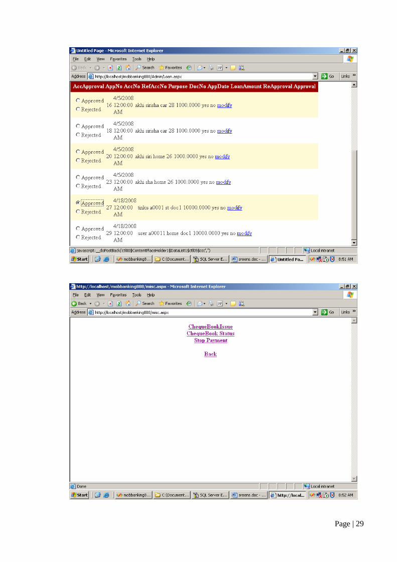
4. Loans Here the user can apply for different types of loans and also he can check
the status for applied loans whether it is sanctioned or not. The administrator
will approve or reject the loan.
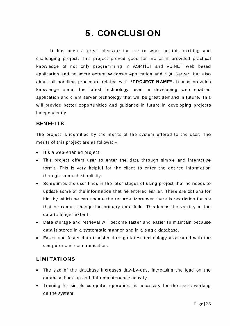
5. Miscellaneous Here there are two options:
• Chequebook Issues

Page | 3
Cheque books will be issued to an account holder whenever he
requests and it should be on the basis of the minimum balance. The chequebook
number generated by the system must be unique.
• Stop Payments Using this option an account holder can add a stop on particular
cheque number. The withdraws on a particular cheque will be stopped upon the
request made by the customer.
6. Closing An Account Using this option, user can close his account; the amount in his account
will be send to him through Draft/Cheque. After closing the account he can’t do
any transactions on that particular account number.
Administrator:
This is the second part of the project where administrator will approve
different requests of the user.
1. Loans Approval Here administrator will approve or reject the loan application applied by
different users. The status of applied loan will be stored in the database and
users can check this status using their mobile.
2. Deposit Approval
Here administrator will approve deposits of different users. When the bank
will get the Cheque/DD of amount to be deposited, the administrator will
approve the deposit and the amount will be added to the respective account.
3. New Account Approval
Here administrator will approve new accounts of different users. When the
bank will get the Cheque/DD of amount to be deposited as initial amount, the
administrator will approve the new account and the amount will be added to the
respective account. After approval only, the user can do the transactions on that
account.

Page | 4
PURPOSE OF THE PROJECT • Need of an application to make bank transactions easily and faster
through mobile.
PROBLEM IN EXISTING SYSTEM
• Cannot Upload and Download the latest updates.
• Risk of mismanagement and of data when the project is under
development.
• No proper coordination between different Applications and Users.
• Fewer Users - Friendly.
SOLUTION OF THESE PROBLEMS The development of the new system contains the following activities, which try
to automate the entire process keeping in view of the database integration
approach.
1. User friendliness is provided in the application with various controls.
2. The system makes the overall project management much easier and
flexible.
3. Readily upload the latest updates, allows user to download the alerts by
clicking the URL.
1.2. HARDWARE & SOFTWARE REQUIREMENTS
HARDWARE REQUIREMENTS: • Intel I5 Processor
• RAM 2GB
• HDD 1TBHard Disk Space
SOFTWARE REQUIREMENTS: • WINDOWS 8.1.
• Visual Studio .Net 2013
• Visual Studio .Net Framework (Minimal for Deployment)
• SQL Server 2012 Enterprise Edition

Page | 5
1.3. PROPOSED SYSTEM To debug the existing system, remove procedures those cause data redundancy,
make navigational sequence proper. To provide information about audits on
different level and also to reflect the current work status depending on
organization/auditor or date. To build strong password mechanism.
FUNCTIONAL FEATURES OF THE MODEL As far as the project is developed the functionality is simple, the objective
of the proposal is to strengthen the functioning of Audit Status Monitoring and
make them effective and better. The entire scope has been classified into five
streams knows as Coordinator Level, management Level, Auditor Level, User
Level and State Web Coordinator Level. The proposed software will cover the
information needs with respect to each request of the user group viz. accepting
the request, providing vulnerability document report and the current status of
the audit.
INPUT AND OUTPUT The main inputs, outputs and major functions of the system are as follows.
Inputs:
• Admin enters his or her user id and password.
• Users enter his or her user id and password.
Outputs:
• Admin allocate user id and password to the users.
• Updates user’s profiles as well as passwords.
PROCESS MODULES USED WITH JUSTIFICATION
ACCESS CONTROL FOR DATA WHICH REQUIRE USER AUTHENTICATION
The following commands specify access control identifiers and they are typically
used to authorize and authenticate the user (command codes are shown in
parentheses)

Page | 6
USER NAME (USER) The user identification is that which is required by the server for access to
its file system. This command will normally be the first command transmitted by
the user after the control connections are made (some servers may require
this).
PASSWORD (PASS) This command must be immediately preceded by the user name
command, and, for some sites, completes the user's identification for access
control. Since password information is quite sensitive, it is desirable in general to
"mask" it or suppress type out.

Page | 7
2. SYSTEM DESIGN
2.1 INTRODUCTION Software design sits at the technical kernel of the software engineering
process and is applied regardless of the development paradigm and area of
application. Design is the first step in the development phase for any engineered
product or system. The designer’s goal is to produce a model or representation
of an entity that will later be built. Beginning, once system requirement have
been specified and analyzed, system design is the first of the three technical
activities -design, code and test that is required to build and verify software.
2.2. E – R DIAGRAMS • The relation upon the system is structure through a conceptual ER-Diagram,
which not only specifics the existential entities but also the standard relations
through which the system exists and the cardinalities that are necessary for
the system state to continue.
• The entity Relationship Diagram (ERD) depicts the relationship between the
data objects. The ERD is the notation that is used to conduct the date
modeling activity the attributes of each data object noted is the ERD can be
described resign a data object descriptions.
• The set of primary components that are identified by the ERD are
Data object Relationships
Attributes Various types of indicators.
The primary purpose of the ERD is to represent data objects and their
relationships.

Page | 8
E–R DIAGRAM:
2.3. DATAFLOW DIAGRAMS Context Level Diagram
SECURITY
UserId
CUSTOMER
PASSWOR
HA
ACCOUNTS LOAN
APPL NO TYPE
APPL
TYPE
DATE
AMOUNT
ACCOUNTS APPROV
ADMINISTRATOR
TRANSACTIONS
MAK
0 Mobile
Banking
Administrator
Customer
Administrator
Customer

Page | 9
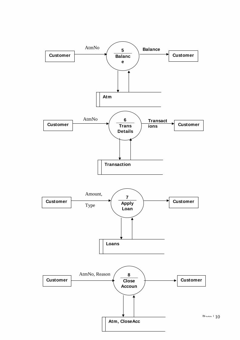
Level – 1
Id, Pwd, Name, Mobile Number
1 Register
Customer Customer Login Id
UserTable
User Table
Options Id, Pwd 2 Login Customer Customer
Balance Amount, AtmNo
3 Deposi
t Customer Customer
Atm, Transaction
Atm, Transaction
Balance Amount, AtmNo
4 Withdr
aw Customer Customer
Page | 10
Atm
AtmNo Balance 5 Balanc
e Customer Customer
Transactions
AtmNo 6 Trans
Details Customer Customer
Transaction
Loans
Amount, Type
7 Apply Loan
Customer Customer
AtmNo, Reason Customer
8 Close
Accoun
Customer
Atm, CloseAcc

Page | 11
Level – 2
AccInfo AtmNo
9 Get Acc
Info Customer Customer
Transact
Customer Approval Type, Atm Nos
10 Approval Admin
UserTable, Transaction, Loan, Atm
Id, Pwd, Name Mobile Number
Login Id Customer
Customer 1.2
Create Acc
1.1 Check
Ref
New_User New_User
AtmNo, Amt
Balance
Customer 4.1 Check Amoun
Balance
4.2 Deduct Amoun
Balance, Transact
Customer

Page | 12
UML DIAGRAMS : 1. Customer:-
2. Administrator:-
<<actor>> (Customer)
Administrator
Create Account
Loans
Transfer
ChequeBook
Closing A
<<actor>> User
registration
Transaction
Loans Status
Cheque Book Status
<<actor>> DataBase

Page | 13
CLASS DIAGRAM :
Loan
Attributes Userid : varchar(20) Accountno : varchar(20) Loanamount : int Date of apply : varchar(20)
Operations +Apply() : void
Withdraw
Attributes Userid : varchar(20) Accountno : varchar(20) Withamount : varchar(20) Date of withdraw : varchar(20)
Operations +withdraw() : void
Deposit
Attributes Userid : varchar(20) Accountno : varchar(20) Deposit amount : varchar(20) Date of apply : varchar(20)
Operations +insert() : void
User login Login id : varchar(20) Password : varchar(20) +submit() : void
New user name : varchar(20) id : varchar(20) email : varchar(20) address : varchar(20) phoneno : varchar(20) account type : varchar(20) minimum salary : varchar(20) date of apply : varchar(20) card type : varchar(20)

Page | 14
2.4.DATA DICTONARY After carefully understanding the requirements of the client the entire
data storage requirements are divided into tables. The below tables are
normalized to avoid any anomalies during the course of data entry.
1. Table Name :-- ACCDETAILS
ColumnName Data Type Length Key userid Varchar 10 accnum Varchar 10 PrimaryKey acctype Varchar 10 balance Money 8 accode Int 4 dop Datetime 8 ddchnum Nchar 10 modeofpay Varchar 15 reference Varchar 15 reapproval Varchar 5 approval Varchar 5
2. Table Name :-- ACCSTATUS
ColumnName Data Type Length Key accnum Varchar 10 PrimaryKey accstatus Varchar 20 userid Varchar 10
3. Table Name :-- ADMINLOGIN
ColumnName Data Type Length Key userid Varchar 10 pwd Varchar 10

Page | 15
4. Table Name :-- CHEQUEBOOKDETAILS
ColumnName Data Type Length Key chebookno Varchar 10 PrimaryKey accno Varchar 10 dateissued Datetime 8 chstartno Varchar 10 chendno Varchar 10 userid Varchar 20 accode Int 4 approve Char 10
5. Table Name :-- DEPOSITDET
ColumnName Data Type Length Key userid Varchar 10 accnum Varchar 10 dbalance Money 8 accode Int 4 dod Datetime 8 modeofpay Varchar 15 ddchnum Nchar 22
6. Table Name :-- LOANS
ColumnName Data Type Length Key appno Int 4 PrimaryKey appdate Datetime 8 userid Varchar 10 reference Varchar 20 purpose Varchar 50 docno Varchar 10 amount Money 8 reapproval Varchar 5 approval Varchar 5
Page | 16
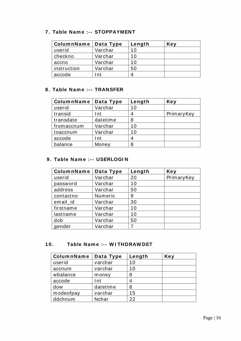
7. Table Name :-- STOPPAYMENT
ColumnName Data Type Length Key userid Varchar 10 checkno Varchar 10 accno Varchar 10 instruction Varchar 50 accode Int 4
8. Table Name :-- TRANSFER
ColumnName Data Type Length Key userid Varchar 10 transid Int 4 PrimaryKey transdate datetime 8 fromaccnum Varchar 10 toaccnum Varchar 10 accode Int 4 balance Money 8
9. Table Name :-- USERLOGIN
ColumnName Data Type Length Key userid Varchar 20 PrimaryKey password Varchar 10 address Varchar 50 contactno Numeric 9 email_id Varchar 30 firstname Varchar 10 lastname Varchar 10 dob Varchar 50 gender Varchar 7
10. Table Name :-- WITHDRAWDET
ColumnName Data Type Length Key userid varchar 10 accnum varchar 10 wbalance money 8 accode Int 4 dow datetime 8 modeofpay varchar 15 ddchnum Nchar 22

Page | 17
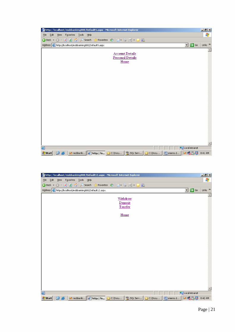
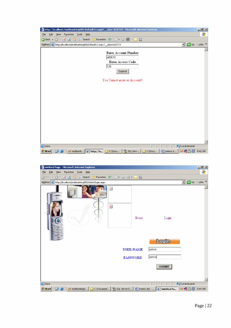
3. OUTPUT SCREENS

Page | 18

Page | 19

Page | 20
Page | 21
Page | 22

Page | 23

Page | 24

Page | 25

Page | 26

Page | 27

Page | 28
Page | 29

Page | 30

Page | 31

Page | 32

Page | 33
4.QR-BARCODE GENERATOR 4.1. .NET QR-Code Barcode Introduction QR-Code is also known as Denso Barcode, QRCode, Quick Response Code, JIS X 0510, ISO/IEC18004. 4.2. Compatibility: Barcode for .NET component is compatible with ISO/IEC 18004 (Second edition 2006-09-01). QR Code is a kind of 2-D (two-dimensional) symbology developed by Denso Wave (a division of Denso Corporation at the time) and released in 1994 with the primary aim of being a symbol that is easily interpreted by scanner equipment. QR Code is capable of handling all types of data, such as numeric and alphabetic characters, Kanji, Kana, Hiragana, symbols, binary, and control codes. The symbol versions of QR Code range from Version 1 to Version 40. Each version has a different module configuration or number of modules (the module refers to the black and white dots that make up QR Code). "Module configuration" refers to the number of modules contained in a symbol, commencing with Version 1 (21 x 21 modules) up to Version 40 (177 x 177 modules). Each higher version number comprises 4 additional modules per side. Each QR Code symbol version has the maximum data capacity according to the amount of data, character type and error correction level. In other words, as the amount of data increases, more modules are required to comprise QR Code, resulting in larger QR Code symbols. QR Code has error correction capability to restore data if the code is dirty or damaged. Four error correction levels are available for users to choose according to the operating environment. Raising this level improves error correction capability but also increases the amount of data QR Code size. To select error correction level, various factors such as the operating environment and QR Code size need to be considered. Level Q or H may be selected for factory environment where QR Code gets dirty, whereas Level L may be selected for clean environment with the large amount of data. Typically, Level M (15%) is most frequently selected. The QR Code error correction feature is implemented by adding a Reed-Solomon Code to the original data. 4.3. .NET QR-Code Basic Characteristics QR Code is a matrix symbology with the following characteristics:
1. Formats: QR Code, with full range of capabilities and maximum data capacity;
2. Encodable character set:
• numeric data (digits 0 - 9); • Alphanumeric data (digits 0 - 9; upper case letters A -Z; nine other
characters: space, $ % * + - . / : );

Page | 34
• byte data (default: ISO/IEC 8859-1); • Kanji characters.
1. Version (Symbol size) (not including quiet zone): 21 x 21 modules to 177 x 177 modules (Versions 1 to 40, increasing in steps of four modules per side).
2. Maximum QR Code symbol size, Version 40-L:
• numeric data: 7089 characters • alphanumeric data: 4296 characters • Byte data: 2953 characters • Kanji data: 1817 characters
1. Selectable error correction level: Four levels of Reed-Solomon error correction (referred to as L, M, Q and H in increasing order of capacity) allowing recovery of:
• L 7% of the symbol codewords • M 15% of the symbol codewords • Q 25% of the symbol codewords • H 30% of the symbol codewords
1. Structured Append: This allows files of data to be represented logically and continuously in up to 16 QR Code symbols.These may be scanned in any sequence to enable the original data to be correctly reconstructed.
2. Extended Channel Interpretations: This mechanism enables data using character sets other than the default encodable set (e.g. Arabic,Cyrillic, Greek) and other data interpretations (e.g. compacted data using defined compression schemes)or other industry-specific requirements to be encoded.
3. FNC1 Mode: FNC1 mode is used for messages containing specific data formats. In the "1st position" it designates data formatted in accordance with the GS1 General Specifications. In the "2nd position" it designates data formatted in accordance with a specific industry application previously agreed with AIM Inc. FNC1 mode applies to the entire symbol and is not affected by subsequent mode indicators.
4.4. .NET QR-Code Encoding Data Scope QRCode Barcode for .NET, ASP.NET supports:
• numeric data (digits 0 - 9); • alphanumeric data (digits 0 - 9; upper case letters A -Z; nine other
characters: space, $ % * + - . / : ); • byte data (default: ISO/IEC 8859-1); • Kanji characters.
Page | 35
5. CONCLUSION
It has been a great pleasure for me to work on this exciting and
challenging project. This project proved good for me as it provided practical
knowledge of not only programming in ASP.NET and VB.NET web based
application and no some extent Windows Application and SQL Server, but also
about all handling procedure related with “PROJECT NAME”. It also provides
knowledge about the latest technology used in developing web enabled
application and client server technology that will be great demand in future. This
will provide better opportunities and guidance in future in developing projects
independently.
BENEFITS:
The project is identified by the merits of the system offered to the user. The
merits of this project are as follows: -
• It’s a web-enabled project.
• This project offers user to enter the data through simple and interactive
forms. This is very helpful for the client to enter the desired information
through so much simplicity.
• Sometimes the user finds in the later stages of using project that he needs to
update some of the information that he entered earlier. There are options for
him by which he can update the records. Moreover there is restriction for his
that he cannot change the primary data field. This keeps the validity of the
data to longer extent.
• Data storage and retrieval will become faster and easier to maintain because
data is stored in a systematic manner and in a single database.
• Easier and faster data transfer through latest technology associated with the
computer and communication.
LIMITATIONS:
• The size of the database increases day-by-day, increasing the load on the
database back up and data maintenance activity.
• Training for simple computer operations is necessary for the users working
on the system.

Page | 36
6. REFERENCES
• FOR .NET INSTALLATION
www.support.microsoft.com
• FOR DEPLOYMENT AND PACKING ON SERVER
www.developer.com
www.15seconds.com
• FOR SQL
www.msdn.microsoft.com
• FOR ASP.NET
www.msdn.microsoft.com/net/quickstart/aspplus/defaul
t.com
www.asp.net
www.fmexpense.com/quickstart/aspplus/default.com
www.asptoday.com
www.aspfree.com
www.4guysfromrolla.com/index.aspx