ml507 bsb ppc440 design creation using edk base … · create the ml507 bsb ppc440 design ... –...
TRANSCRIPT
© Copyright 2010 Xilinx
ML507 BSB PPC440 Base System Builder Design Creation
May 2010
© Copyright 2010 Xilinx

Overview
ML507 and BSB Hardware Overview– Software Requirements– ML507 Setup– Using the Pre-Built Design
Create the ML507 BSB PPC440 Design– Generate the ELF Files– Generate the Bitstream
Download the Bitstream into the ML507 Loading a Bootloop ELF into the Block RAM
– Running the TestApp Peripheral
References
Note: This Presentation applies to the ML507
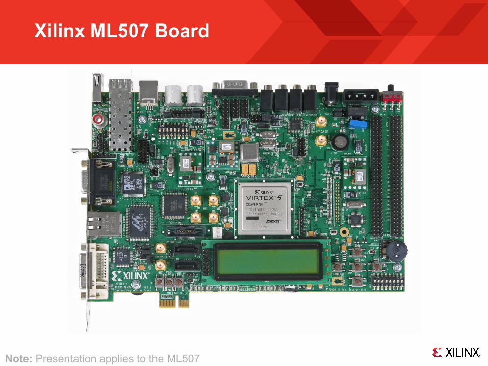
Xilinx ML507 Board
Note: Presentation applies to the ML507
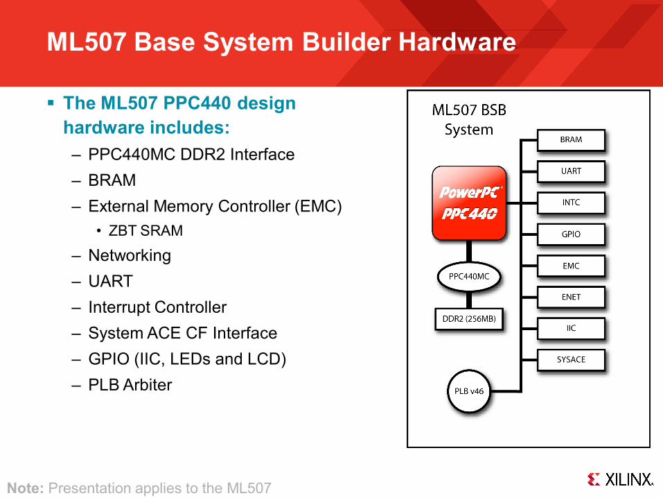
ML507 Base System Builder Hardware
The ML507 PPC440 design hardware includes:– PPC440MC DDR2 Interface– BRAM – External Memory Controller (EMC)
• ZBT SRAM
– Networking – UART– Interrupt Controller– System ACE CF Interface– GPIO (IIC, LEDs and LCD)– PLB Arbiter
Note: Presentation applies to the ML507
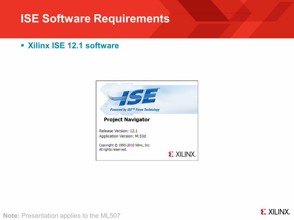
ISE Software Requirements
Xilinx ISE 12.1 software
Note: Presentation applies to the ML507
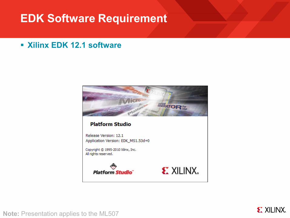
EDK Software Requirement
Xilinx EDK 12.1 software
Note: Presentation applies to the ML507
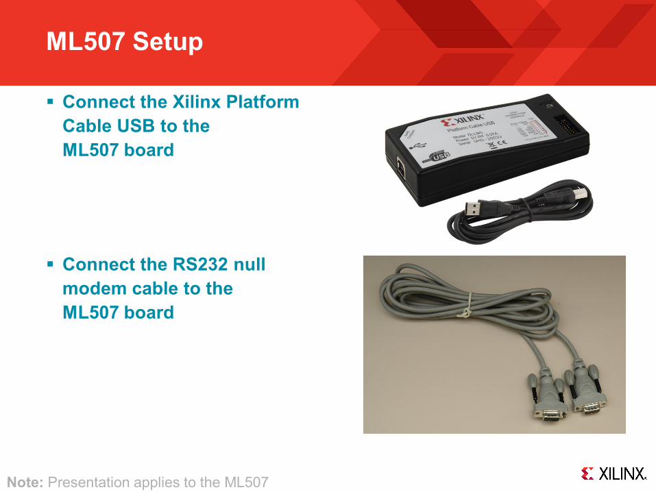
ML507 Setup
Connect the Xilinx Platform Cable USB to the ML507 board
Connect the RS232 nullmodem cable to the ML507 board
Note: Presentation applies to the ML507

ML507 Setup
Set ML507 Jumpers for GMII– Set both J22 and J23 to positions 1-2 (as shown)
Note: Presentation applies to the ML507
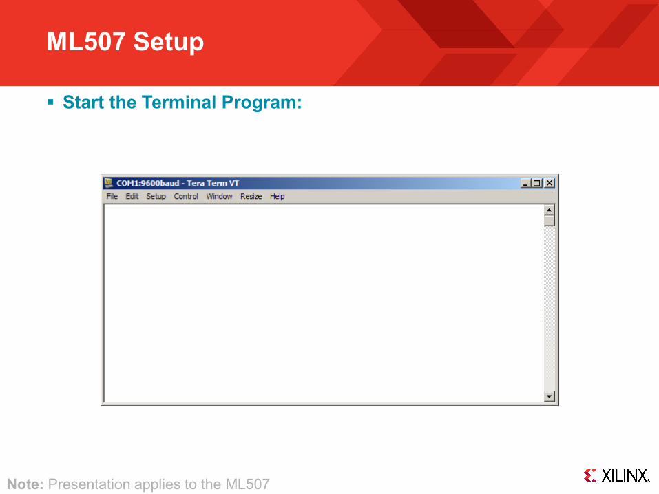
ML507 Setup
Start the Terminal Program:
Note: Presentation applies to the ML507

Additional ML507 Setup Details
Refer to ml505_overview_setup.ppt for details on:– Software Requirements– ML505/506/507 Board Setup– Equipment and Cables– Software– Network
Terminal Programs– This presentation requires the
9600-8-N-1 Baud terminal setup
Note: Presentation applies to the ML507
Using the Pre-Built Design
Unzip ml507_bsb_design_ppc440.zip and locate pre-built bitstream and executable software files:– ml507_bsb_design_ppc440/implementation/download.bit– ml507_bsb_design_ppc440/microblaze_0/code/*.elf
Configure FPGA– Launch XPS project, ml507_bsb_system.xmp– From the menu, select Project → Launch EDK Shell and type:
impact -batch etc/download.cmd– Go to Slide 35, to run the software application
For a tutorial on how to create the contents of the ml507_bsb_design_ppc440.zip continue to the next slide
Note: Presentation applies to the ML507
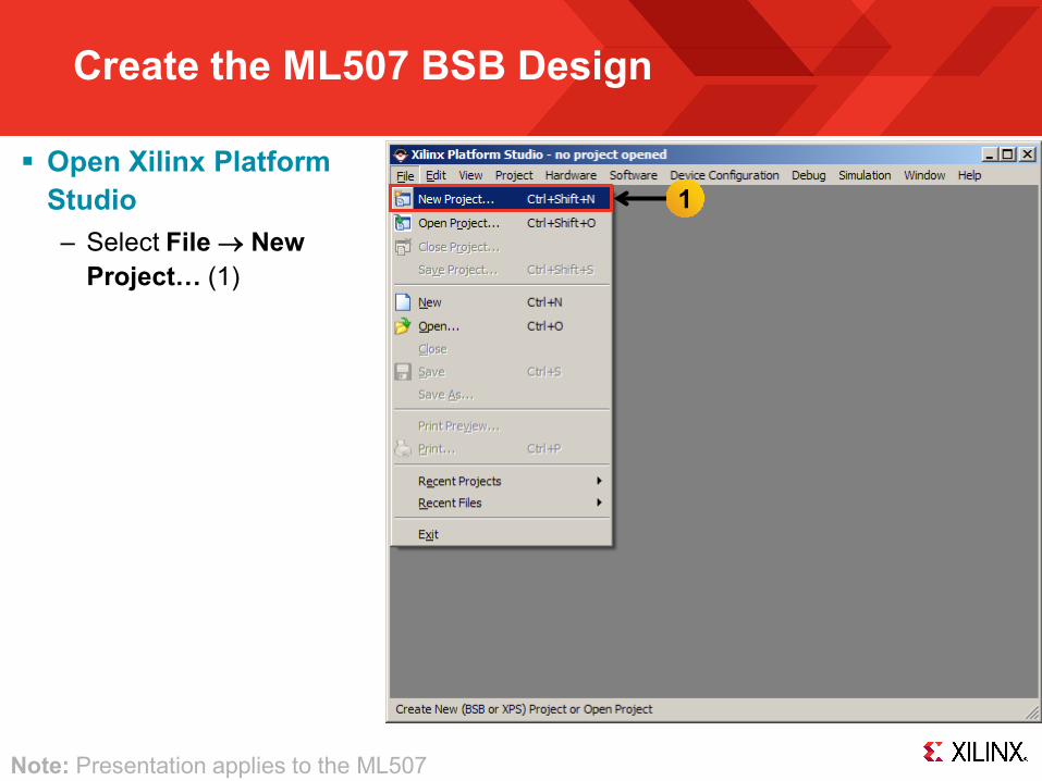
Create the ML507 BSB Design
Open Xilinx Platform Studio– Select File → New
Project… (1)
Note: Presentation applies to the ML507
1

Create the ML507 BSB Design
Select Base System Builder wizard (1)
Note: Presentation applies to the ML507
1
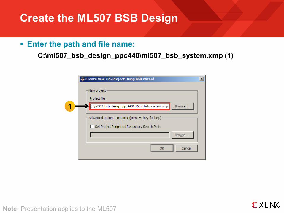
Create the ML507 BSB Design
Enter the path and file name: C:\ml507_bsb_design_ppc440\ml507_bsb_system.xmp (1)
Note: Presentation applies to the ML507
1

Create the ML507 BSB Design
Create a new design (1)
Note: Presentation applies to the ML507
1

Create the ML507 BSB Design
Select– Virtex-5 ML507
Evaluation Platform (1)
Note: Presentation applies to the ML507
1

Create the ML507 BSB Design
Select Single Processor (1)
Note: Presentation applies to the ML507
1
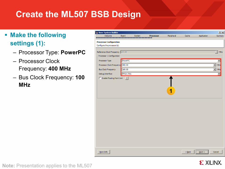
Create the ML507 BSB Design
Make the following settings (1):– Processor Type: PowerPC– Processor Clock
Frequency: 400 MHz– Bus Clock Frequency: 100
MHz
Note: Presentation applies to the ML507
1
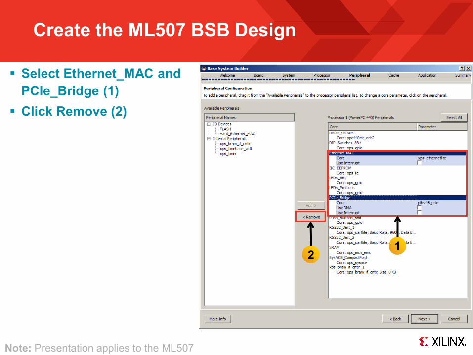
Create the ML507 BSB Design
Select Ethernet_MAC and PCIe_Bridge (1)
Click Remove (2)
Note: Presentation applies to the ML507
12
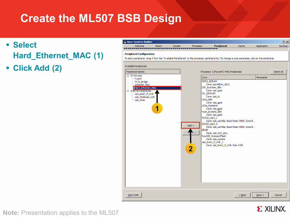
Create the ML507 BSB Design
Select Hard_Ethernet_MAC (1)
Click Add (2)
Note: Presentation applies to the ML507
2
1
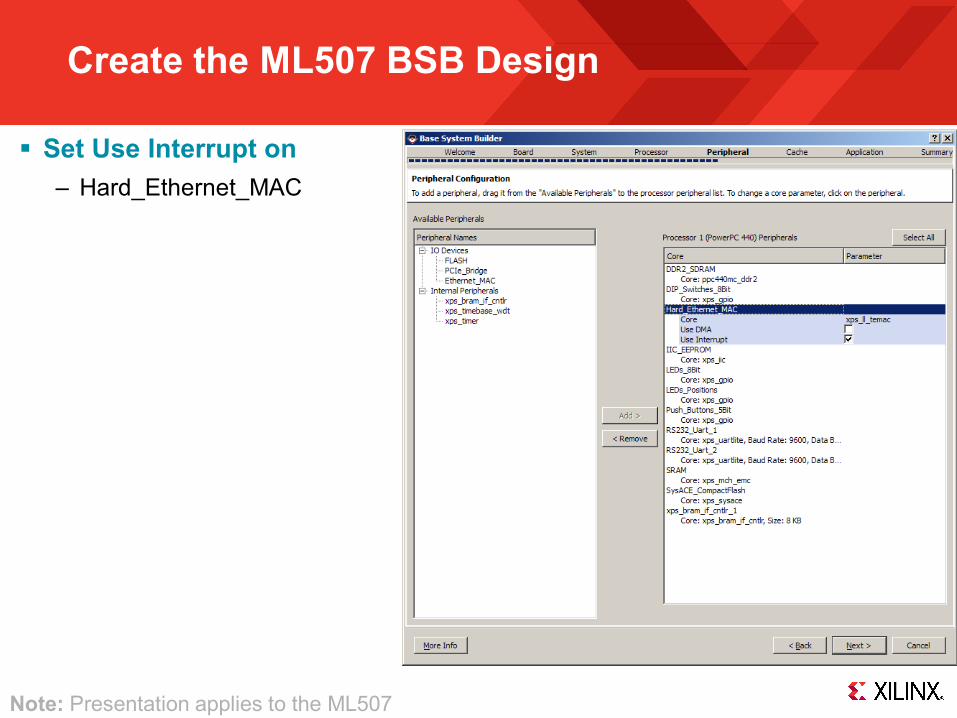
Create the ML507 BSB Design
Set Use Interrupt on– Hard_Ethernet_MAC
Note: Presentation applies to the ML507
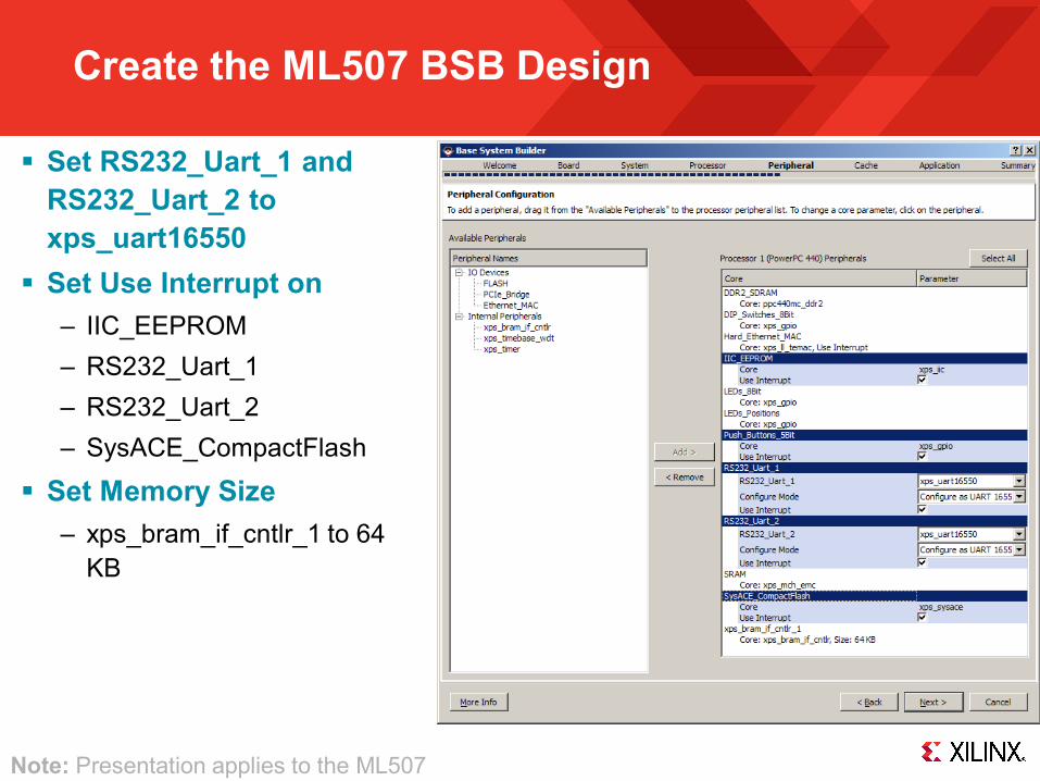
Create the ML507 BSB Design
Set RS232_Uart_1 and RS232_Uart_2 to xps_uart16550
Set Use Interrupt on– IIC_EEPROM– RS232_Uart_1– RS232_Uart_2– SysACE_CompactFlash
Set Memory Size– xps_bram_if_cntlr_1 to 64
KB
Note: Presentation applies to the ML507
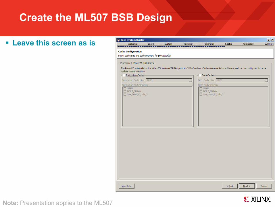
Create the ML507 BSB Design
Leave this screen as is
Note: Presentation applies to the ML507
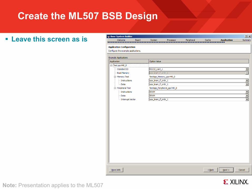
Create the ML507 BSB Design
Leave this screen as is
Note: Presentation applies to the ML507
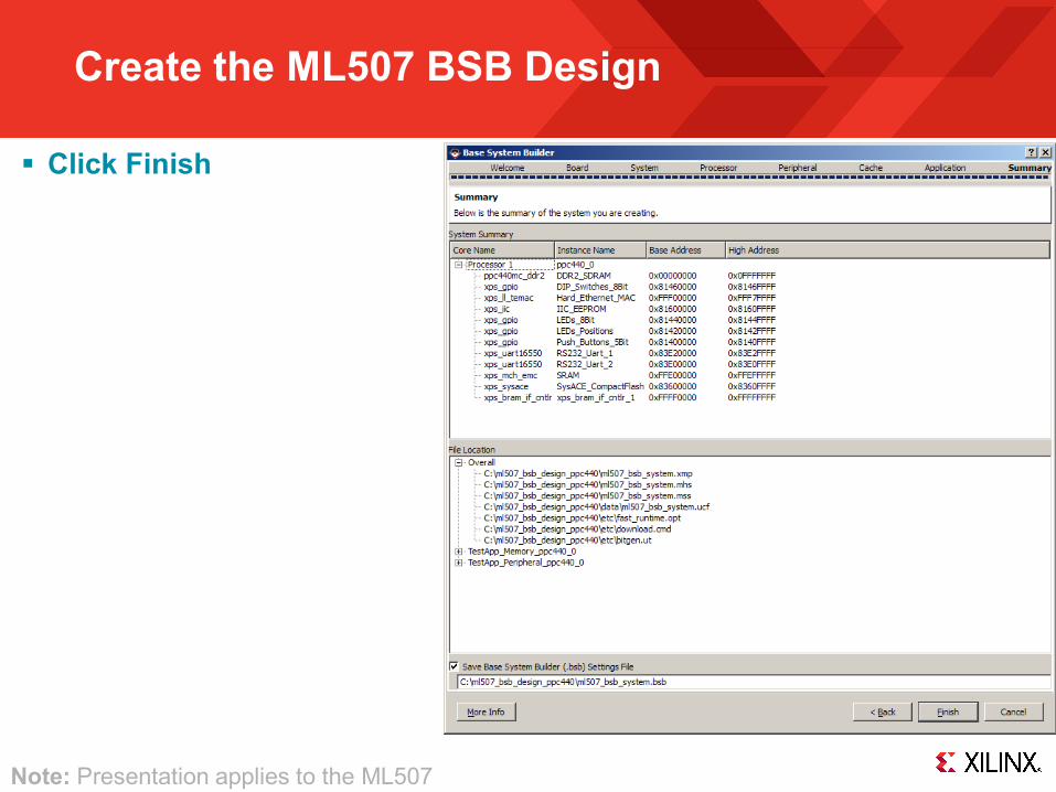
Create the ML507 BSB Design
Click Finish
Note: Presentation applies to the ML507

Generate the ELF Files
Generate the libraries needed to create the bitstream– Select Software →
Generate Libraries and BSPs (1)
Note: Presentation applies to the ML507
1

Generate the ELF Files
Compile the Software Applications and create an executable (executable.elf)– Select Software →
Build All User Applications (1)
Note: Presentation applies to the ML507
1
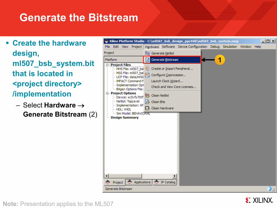
Generate the Bitstream
Create the hardware design, ml507_bsb_system.bit that is located in <project directory>/implementation– Select Hardware →
Generate Bitstream (2)
Note: Presentation applies to the ML507
1
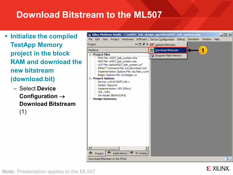
Download Bitstream to the ML507
Initialize the compiled TestApp Memory project in the block RAM and download the new bitstream (download.bit)– Select Device
Configuration →Download Bitstream(1)
Note: Presentation applies to the ML507
1

Download Bitstream to the ML507
View the output of a successful bitstream download in the terminal window
Note: Presentation applies to the ML507
Loading a Bootloop ELF into the Block RAM
A concatenated software/hardware file, known as an ACE file, is useful for loading large programs, such as a Linux, VxWorks, or U-Boot into the external memory
A bootloop program must be used to occupy the processor until the software is loaded into memory
The following pages show how to initialize a bootloopprogram into Block RAM and to test its existence
Note: Presentation applies to the ML507
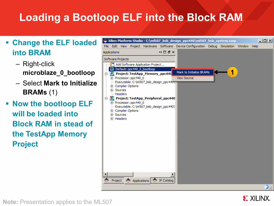
Loading a Bootloop ELF into the Block RAM
Change the ELF loaded into BRAM – Right-click
microblaze_0_bootloop – Select Mark to Initialize
BRAMs (1)
Now the bootloop ELF will be loaded into Block RAM in stead of the TestApp Memory Project
1
Note: Presentation applies to the ML507
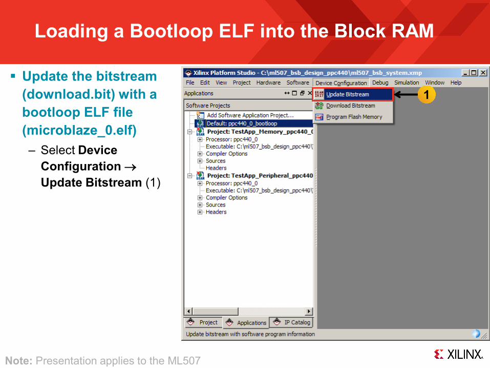
Loading a Bootloop ELF into the Block RAM
Update the bitstream (download.bit) with a bootloop ELF file (microblaze_0.elf)– Select Device
Configuration →Update Bitstream (1)
1
Note: Presentation applies to the ML507

Loading a Bootloop ELF into the Block RAM
Load the new design onto the FPGA and load the bootloop program into the Block RAM– Select Device
Configuration →Download Bitstream (1)
1
Note: Presentation applies to the ML507
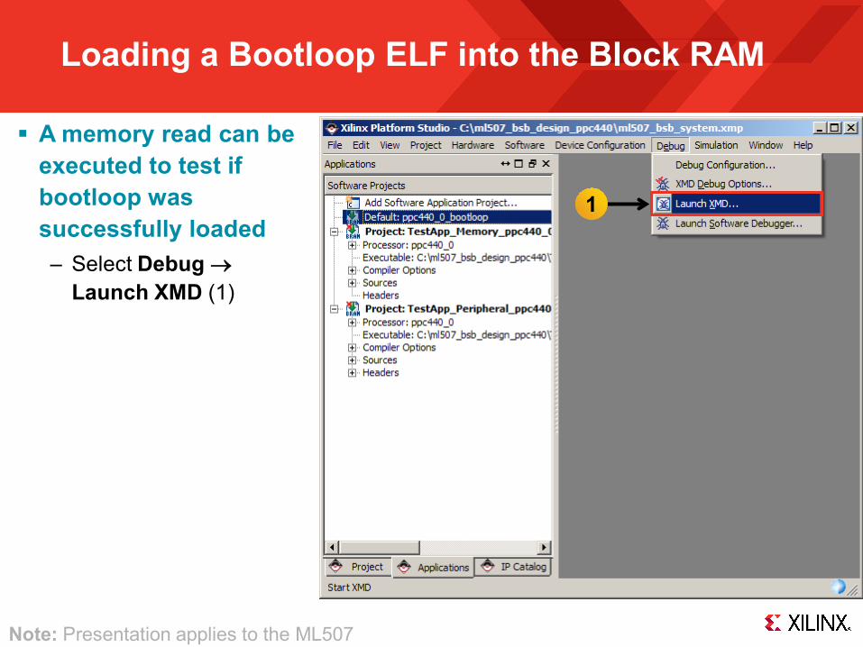
Loading a Bootloop ELF into the Block RAM
A memory read can be executed to test if bootloop was successfully loaded– Select Debug →
Launch XMD (1)
1
Note: Presentation applies to the ML507
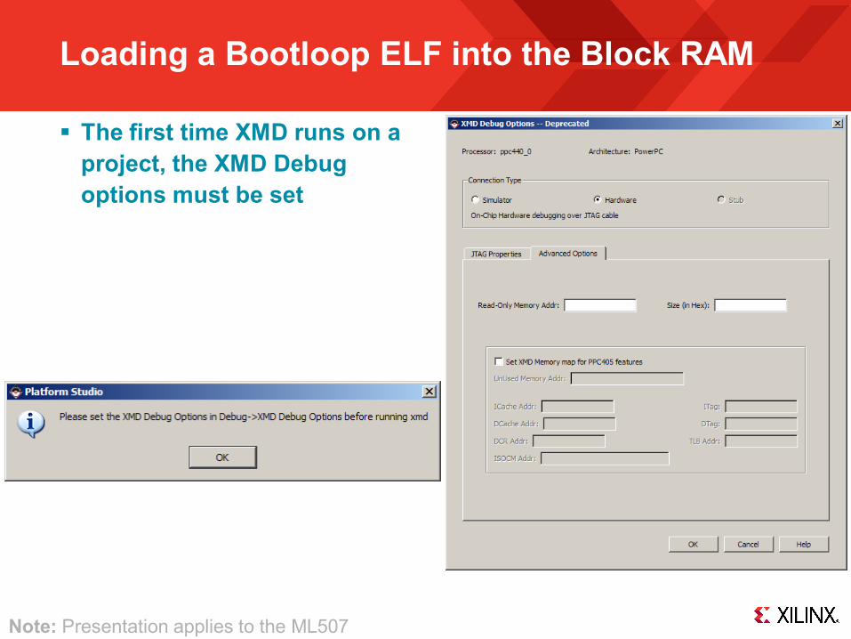
Loading a Bootloop ELF into the Block RAM
The first time XMD runs on a project, the XMD Debug options must be set
Note: Presentation applies to the ML507
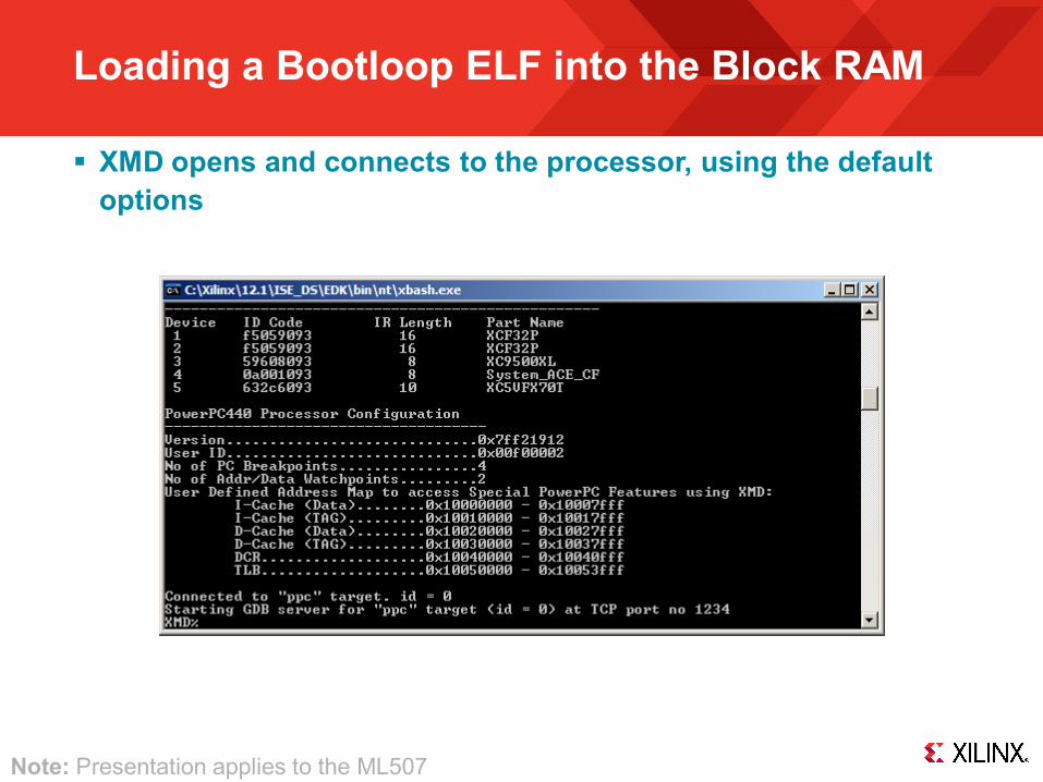
Loading a Bootloop ELF into the Block RAM
XMD opens and connects to the processor, using the default options
Note: Presentation applies to the ML507
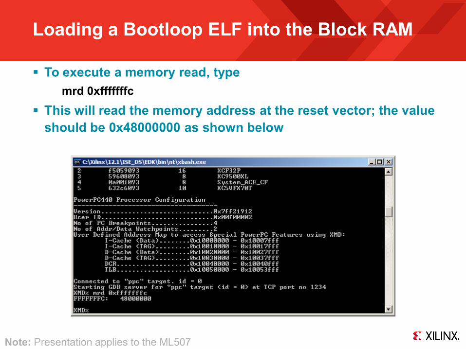
Loading a Bootloop ELF into the Block RAM
To execute a memory read, type mrd 0xfffffffc
This will read the memory address at the reset vector; the value should be 0x48000000 as shown below
Note: Presentation applies to the ML507
Running the TestApp Peripheral
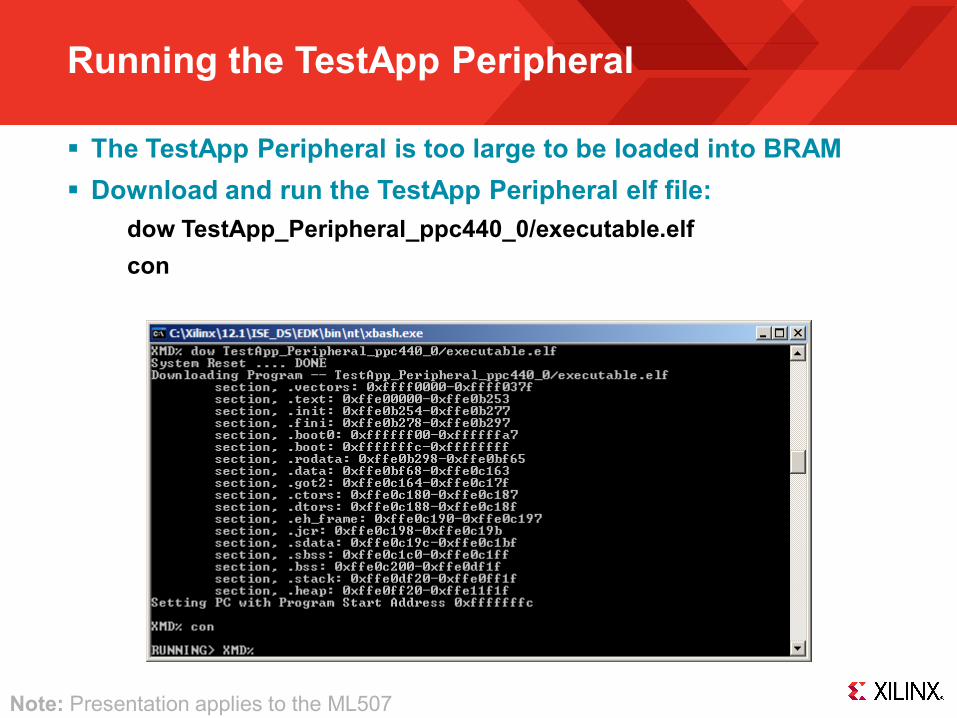
The TestApp Peripheral is too large to be loaded into BRAM Download and run the TestApp Peripheral elf file:
dow TestApp_Peripheral_ppc440_0/executable.elfcon
Note: Presentation applies to the ML507
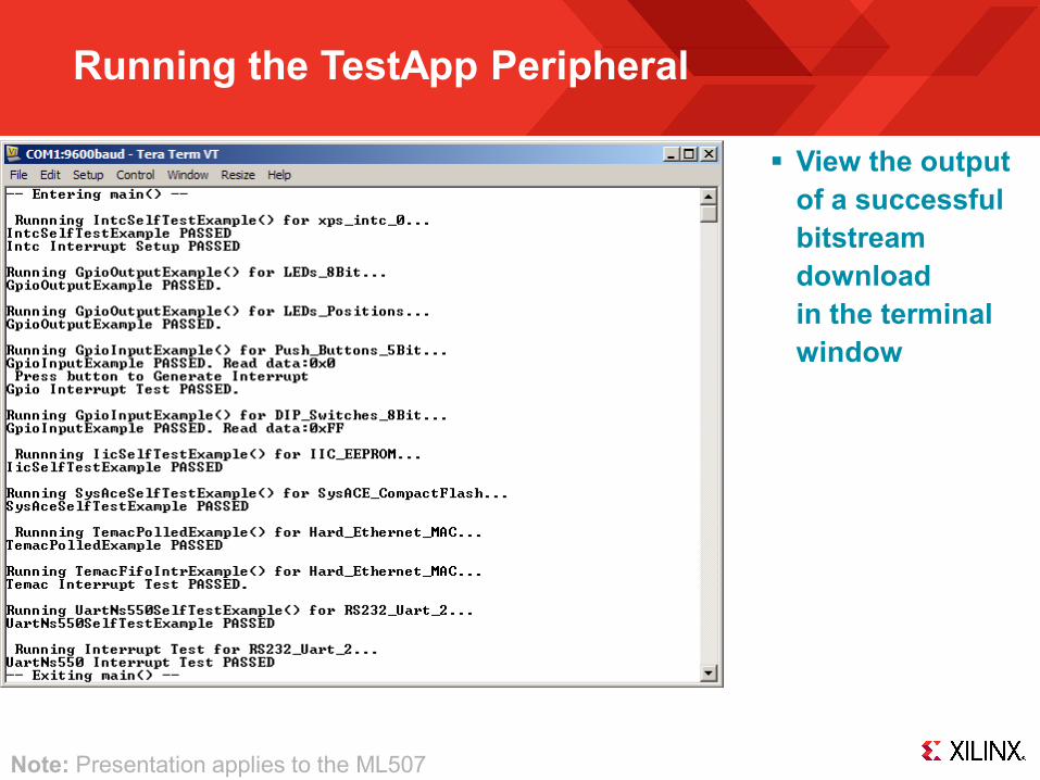
Running the TestApp Peripheral
View the output of a successful bitstream download in the terminal window
Note: Presentation applies to the ML507

References
References
Virtex-5– Virtex-5 FPGA Family
http://www.xilinx.com/products/virtex5/index.htm
Platform Studio– Embedded Development Kit (EDK) Resources
http://www.xilinx.com/tools/platform.htm– Embedded System Tools Reference Manual
http://www.xilinx.com/support/documentation/sw_manuals/xilinx12_1/est_rm.pdf– EDK Concepts, Tools, and Techniques
http://www.xilinx.com/support/documentation/sw_manuals/xilinx12_1/edk_ctt.pdf

Documentation
Documentation
ML505/506/507 Documentation– ML505 Overview
http://www.xilinx.com/ml505– ML506 Overview
http://www.xilinx.com/ml506– ML507 Overview
http://www.xilinx.com/ml507– ML505/506/507 Evaluation Platform User Guide – UG347
http://www.xilinx.com/support/documentation/boards_and_kits/ug347.pdf– ML505/506/507 Getting Started Tutorial – UG348
http://www.xilinx.com/support/documentation/boards_and_kits/ug348.pdf– ML505/506/507 Reference Design User Guide – UG349
http://www.xilinx.com/support/documentation/boards_and_kits/ug349.pdf