12 edk overview
TRANSCRIPT
1
© 2010 Xilinx, Inc. All Rights ReservedThis material exempt per Department of Commerce license exception TSU
EDK Overview
© 2010 Xilinx, Inc. All Rights Reserved For Academic Use Only
Objectives
After completing this module, you will be able to:
• Describe the embedded systems development flow
• Describe the components in the hardware design
• Specify ways to create a hardware design
• Identify the tools included in the Embedded Development Kit
(EDK)
12- 2 EDK Overview
2
© 2010 Xilinx, Inc. All Rights Reserved For Academic Use Only
Outline
• Introduction
• EDK
– Overview of EDK
– Embedded Development Design Flow
– Embedded Project Management
• Supported Platforms
• Appendix: Project Files and Structure
12- 3 EDK Overview
© 2010 Xilinx, Inc. All Rights Reserved For Academic Use Only
Embedded System
• An embedded system is nearly any computing system (other than
a general-purpose computer) with the following characteristics:
– Single function
• Typically designed to perform a predefined function
– Tightly constrained
• Tuned for low cost
• Single-to-fewer component based
• Performs functions fast enough
• Consumes minimum power
– Reactive and real-time
• Must continually monitor the desired environment and react to changes
– Hardware and software coexistence
12- 4 EDK Overview

3
© 2010 Xilinx, Inc. All Rights Reserved For Academic Use Only
Embedded Systems
• Examples:
– Mobile phone systems
• Customer handsets and base stations
– Automotive applications
• Braking systems, traction control, airbag release systems, and cruise-control
applications
– Aerospace applications
• Flight-control systems, engine controllers, auto-piloting systems, and
passenger in-flight entertainment systems
– Defense systems
• Radar systems, fighter aircraft flight-control systems, radio systems, and
missile guidance systems
12- 5 EDK Overview
© 2010 Xilinx, Inc. All Rights Reserved For Academic Use Only
Current Technologies
• Microcontroller-based systems
• DSP processor-based systems
• ASIC technology
• FPGA technology
12- 6 EDK Overview
4
© 2010 Xilinx, Inc. All Rights Reserved For Academic Use Only
Embedded Software Tools
CPU
Logic Design Tools
I/O
FPGA
Memory
Logic Design Tools
FPGA +
Memory + IP +
High Speed IO
(4K & Virtex)
Embedded Software Tools
CPU
Inte
gra
tio
n o
f F
un
ctio
ns
Inte
gra
tio
n o
f F
un
ctio
ns
TimeTime
Logic Design Tools
Embedded Software Tools
Logic + Memory
+ IP +
Processors +
RocketIO
(Virtex-II Pro)
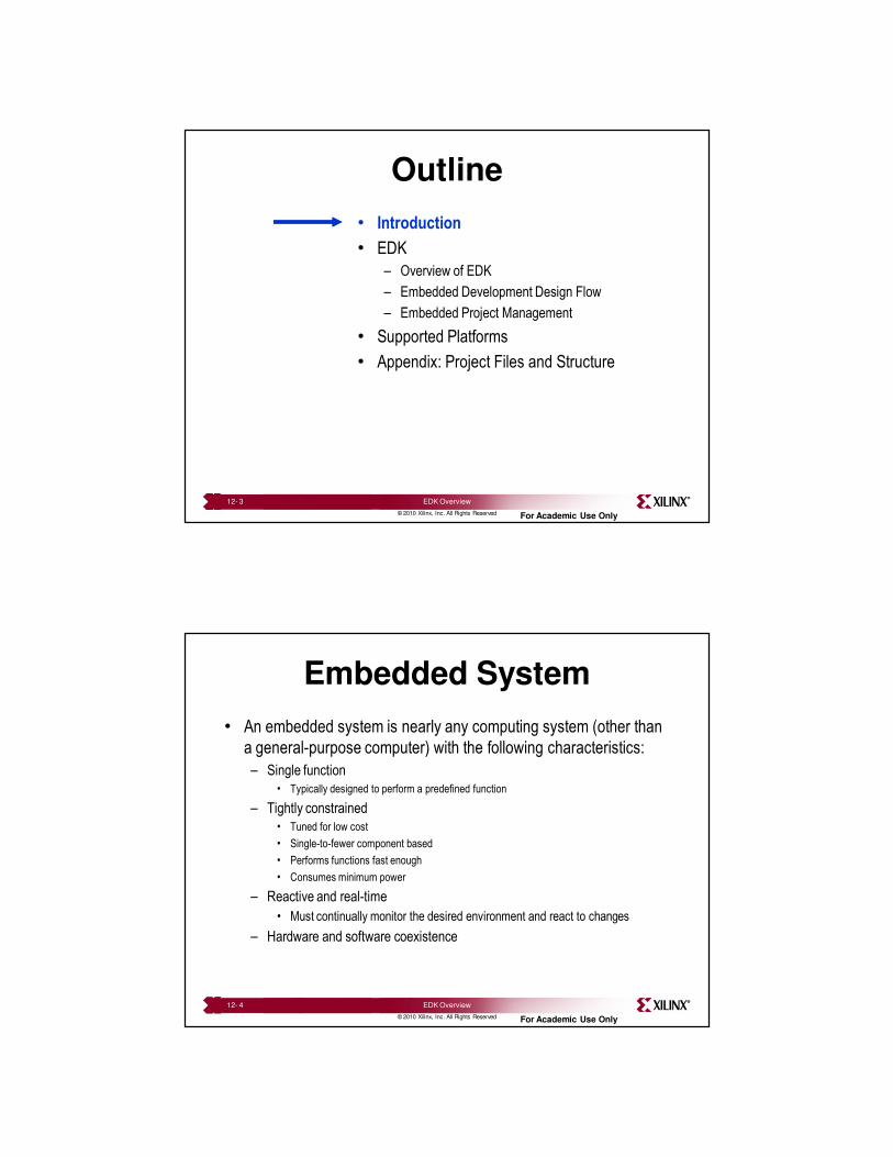
Programmable systems
usher in a new era of system
design integration
possibilities
Programmable systems
usher in a new era of system
design integration
possibilities
Integration in System Design
12- 7 EDK Overview
© 2010 Xilinx, Inc. All Rights Reserved For Academic Use Only
Embedded Design in an FPGA
• Embedded design in an FPGA consists of the following:
– Develop FPGA hardware design
– Generate drivers and libraries
– Create the software application
• Software routines
• Interrupt service routines (optional)
• Operating System (OS) or Real Time Operating System (RTOS) (optional)
12- 8 EDK Overview
5
© 2010 Xilinx, Inc. All Rights Reserved For Academic Use Only
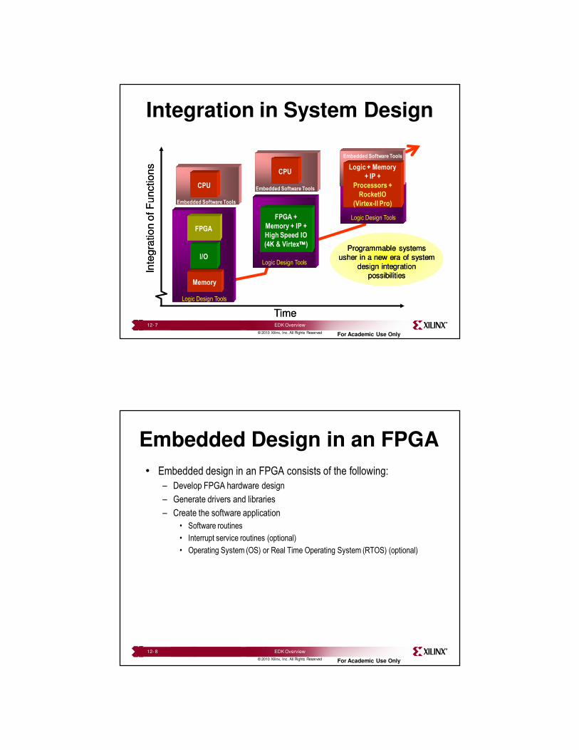
MicroBlaze Processor-Based Embedded Design
MicroBlaze32-Bit RISC Core
UART10/100
E-Net
Memory
Controller
Off-ChipMemory
FLASH/SRAM
Fast Simplex
Link
0,1….15
Custom
FunctionsCustom
Functions
BRAMLocal Memory
Bus
D-Cache
BRAM
I-Cache
BRAM
Configurable
Sizes
Arb
iter PLB
Processor Local Bus
CacheLink
SDRAM
Processor Local Bus
GPIO
BusBridge
PLB
Arb
iter
On-Chip
Peripheral
13- 9 Hardware Design
Another segment of PLB necessary when
slow devices to be operated at slower bus
speed enabling higher-performance system
Arbiter required only when a peripheral is
master capable and wants to write to
peripheral on the other segment
This is a v7.3 architecture. Versions 7.0, 7.1, and 7.2 supported OPB bus off the core if PLB interface was disabled
Versions 6.0 or earlier did not support PLB bus off the processor. Instead they had OPB bus
© 2010 Xilinx, Inc. All Rights Reserved For Academic Use Only
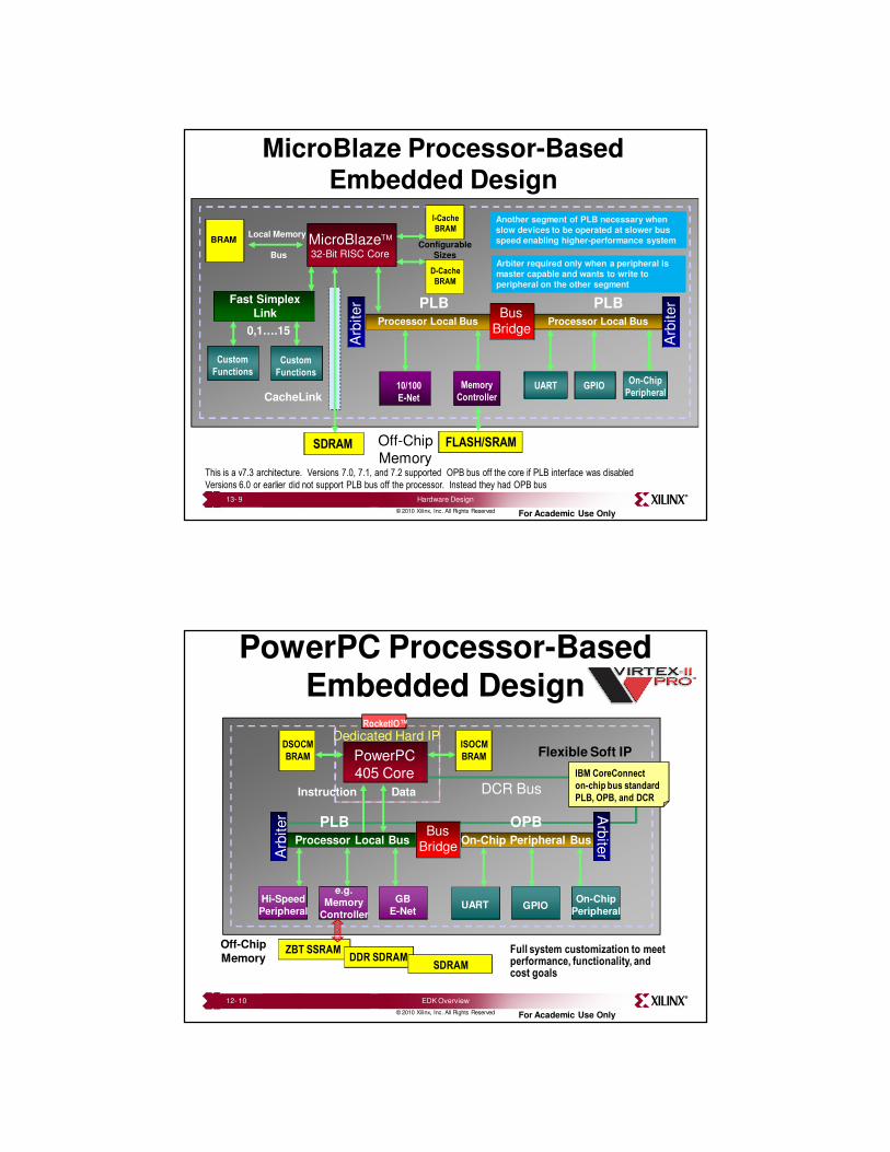
PowerPC Processor-Based Embedded Design
PowerPC405 Core
Dedicated Hard IP
Flexible Soft IP
RocketIO™
Full system customization to meet performance, functionality, and cost goals
DCR Bus
UART GPIOOn-Chip
Peripheral
Hi-Speed
Peripheral
GB
E-Net
e.g.
Memory
Controller
Arb
iter
On-Chip Peripheral Bus
OPB
Arb
iter
Processor Local Bus
Instruction Data
PLB
DSOCM
BRAM
ISOCM
BRAM
Off-Chip
MemoryZBT SSRAM
DDR SDRAMSDRAM
BusBridge
IBM CoreConnect
on-chip bus standard
PLB, OPB, and DCR
12- 10 EDK Overview
6
© 2010 Xilinx, Inc. All Rights Reserved For Academic Use Only
Outline
• Introduction
• EDK
– Overview of EDK
– Embedded Development Design Flow
– Embedded Project Management
• Supported Platforms
• Appendix: Project Files and Structure
12- 11 EDK Overview
© 2010 Xilinx, Inc. All Rights Reserved For Academic Use Only
Embedded Development Kit
• What is Embedded Development Kit (EDK)?
– The Embedded Development Kit is the Xilinx software suite for
designing complete embedded programmable systems
– The kit includes all the tools, documentation, and IP that you
require for designing systems with embedded IBM PowerPC™
hard processor cores, and/or Xilinx MicroBlaze™ soft
processor cores
– It enables the integration of both hardware and software
components of an embedded system
12- 12 EDK Overview
7
© 2010 Xilinx, Inc. All Rights Reserved For Academic Use Only
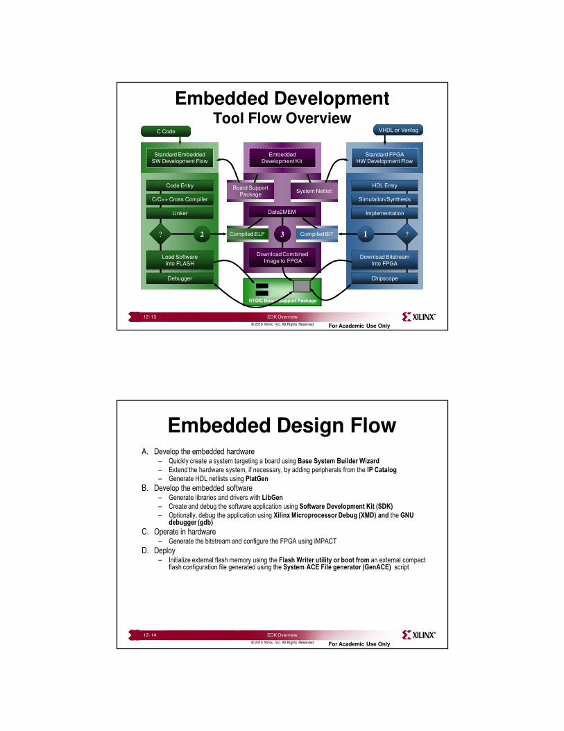
Embedded DevelopmentTool Flow Overview
Data2MEM
Download Combined
Image to FPGA
Compiled ELF Compiled BIT
RTOS, Board Support Package
Embedded
Development Kit
Instantiate the
‘System Netlist’
and Implement
the FPGA
?
HDL Entry
Simulation/Synthesis
Implementation
Download Bitstream
Into FPGA
Chipscope
Standard FPGA
HW Development Flow
VHDL or Verilog
System NetlistInclude the BSP
and Compile the
Software Image
?
Code Entry
C/C++ Cross Compiler
Linker
Load Software
Into FLASH
Debugger
Standard Embedded
SW Development Flow
C Code
Board Support
Package
12 3 Compiled BITCompiled ELF
12- 13 EDK Overview
© 2010 Xilinx, Inc. All Rights Reserved For Academic Use Only
Embedded Design FlowA. Develop the embedded hardware
– Quickly create a system targeting a board using Base System Builder Wizard
– Extend the hardware system, if necessary, by adding peripherals from the IP Catalog
– Generate HDL netlists using PlatGen
B. Develop the embedded software– Generate libraries and drivers with LibGen
– Create and debug the software application using Software Development Kit (SDK)
– Optionally, debug the application using Xilinx Microprocessor Debug (XMD) and the GNU debugger (gdb)
C. Operate in hardware– Generate the bitstream and configure the FPGA using iMPACT
D. Deploy– Initialize external flash memory using the Flash Writer utility or boot from an external compact
flash configuration file generated using the System ACE File generator (GenACE) script
12- 14 EDK Overview
8
© 2010 Xilinx, Inc. All Rights Reserved For Academic Use Only
Simulation
Generator
Hardware
Platform Generation
Library Generation
Embedded Software
Development
ISETools
IP Library or User Repository
MSS
LibGen
.a
Compiler (GCC)
.o, .a
Linker (GCC)
ELF
MHS
PlatGenDrivers,
MDDMPD, PAO
PcoreHDL
System andWrapper VHD
system.bmm
Synthesis (XST)
NGC
NGDBuildUCF
NGD
MAP, PAR
NCD
BitGensystem_bd.bmm
BITINIT
download.bit
iMPACT
system.bit
SimGen
BehavioralVHD Model
SimGen
StructuralVHD Model
SimGen
TimingVHD Model
Simulation
IP Models ISE Models
CompXLib
ApplicationSource.c, .h, .s
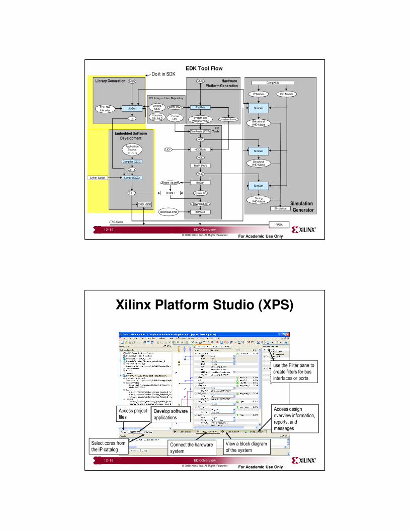
EDK Tool Flow
download.cmd
EDK SWLibraries
Libraries,OS, MLD
XMD, GDB
FPGAJTAG Cable
Linker Script
Do it in SDK
12- 15 EDK Overview
© 2010 Xilinx, Inc. All Rights Reserved For Academic Use Only
Xilinx Platform Studio (XPS)
Select cores from
the IP catalog
Develop software
applications
Access project
files
Connect the hardware
system
View a block diagram
of the system
Access design
overview information,
reports, and
messages
use the Filter pane to
create filters for bus
interfaces or ports
12- 16 EDK Overview
9
© 2010 Xilinx, Inc. All Rights Reserved For Academic Use Only
XPS Functions
• Project management
– Creation of Microprocessor Hardware
Specification (MHS) or Microprocessor
Software Specification (MSS) file
– Xilinx Microprocessor Project (XMP) file
• Platform management
– Tool flow settings
– Software platform settings
– Tool invocation
– Debug and simulation
12- 17 EDK Overview
© 2010 Xilinx, Inc. All Rights Reserved For Academic Use Only
Outline
• Introduction
• EDK– Overview of EDK
– Embedded Development Design Flow
– Embedded Project Management
• Supported Platforms
• Appendix: Project Files and Structure
12- 18 EDK Overview
10
© 2010 Xilinx, Inc. All Rights Reserved For Academic Use Only
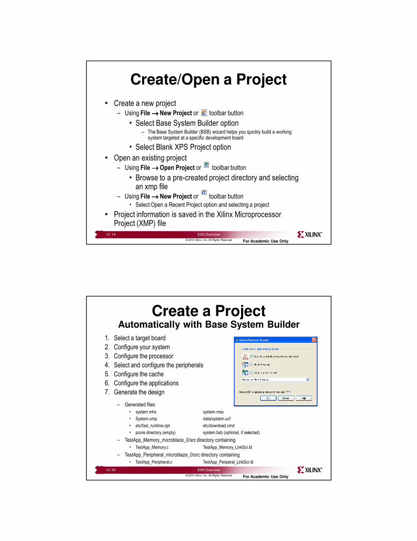
Create/Open a Project
• Create a new project– Using File →→→→ New Project or toolbar button
• Select Base System Builder option– The Base System Builder (BSB) wizard helps you quickly build a working
system targeted at a specific development board
• Select Blank XPS Project option
• Open an existing project– Using File →→→→ Open Project or toolbar button
• Browse to a pre-created project directory and selecting an xmp file
– Using File →→→→ New Project or toolbar button
• Select Open a Recent Project option and selecting a project
• Project information is saved in the Xilinx Microprocessor Project (XMP) file
12- 19 EDK Overview
© 2010 Xilinx, Inc. All Rights Reserved For Academic Use Only
Create a Project Automatically with Base System Builder
1. Select a target board
2. Configure your system
3. Configure the processor
4. Select and configure the peripherals
5. Configure the cache
6. Configure the applications
7. Generate the design
– Generated files:
• system.mhs system.mss
• System.xmp data/system.ucf
• etc/fast_runtime.opt etc/download.cmd
• pcore directory (empty) system.bsb (optional, if selected)
– TestApp_Memory_microblaze_0/src directory containing
• TestApp_Memory.c TestApp_Memory_LinkScr.ld
– TestApp_Peripheral_microblaze_0/src directory containing
• TestApp_Peripheral.c TestApp_Periperal_LinkScr.ld
12- 20 EDK Overview
11
© 2010 Xilinx, Inc. All Rights Reserved For Academic Use Only
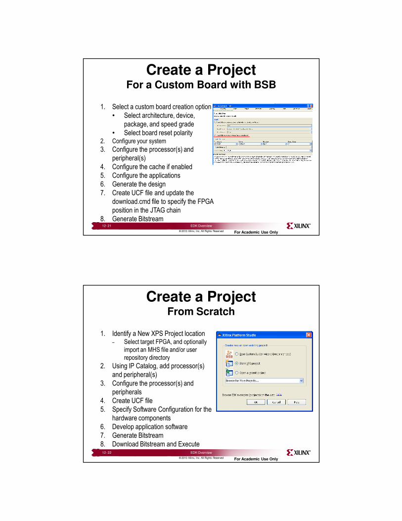
Create a ProjectFor a Custom Board with BSB
1. Select a custom board creation option
• Select architecture, device,
package, and speed grade
• Select board reset polarity2. Configure your system
3. Configure the processor(s) and
peripheral(s)
4. Configure the cache if enabled
5. Configure the applications
6. Generate the design
7. Create UCF file and update the
download.cmd file to specify the FPGA
position in the JTAG chain
8. Generate Bitstream12- 21 EDK Overview
© 2010 Xilinx, Inc. All Rights Reserved For Academic Use Only
Create a ProjectFrom Scratch
1. Identify a New XPS Project location– Select target FPGA, and optionally
import an MHS file and/or user
repository directory
2. Using IP Catalog, add processor(s)
and peripheral(s)
3. Configure the processor(s) and
peripherals
4. Create UCF file
5. Specify Software Configuration for the
hardware components
6. Develop application software
7. Generate Bitstream
8. Download Bitstream and Execute12- 22 EDK Overview
12
© 2010 Xilinx, Inc. All Rights Reserved For Academic Use Only
Hardware Creation Flow
Simulation
Generator
Hardware
Platform Generation
Library Generation
Embedded Software
Development
ISETools
IP Library or User Repository
MSS
LibGen
.a
Compiler (GCC)
.o, .a
Linker (GCC)
ELF
MHS
PlatGenDrivers,
MDDMPD, PAO
PcoreHDL
System andWrapper VHD
system.bmm
Synthesis (XST)
NGC
NGDBuildUCF
NGD
MAP, PAR
NCD
BitGensystem_bd.bmm
BITINIT
download.bit
iMPACT
system.bit
SimGen
BehavioralVHD Model
SimGen
StructuralVHD Model
SimGen
TimingVHD Model
Simulation
IP Models ISE Models
CompXLib
ApplicationSource.c, .h, .s
download.cmd
EDK SWLibraries
Libraries,OS, MLD
XMD, GDB
FPGAJTAG Cable
Linker Script
12- 23 EDK Overview
© 2010 Xilinx, Inc. All Rights Reserved For Academic Use Only
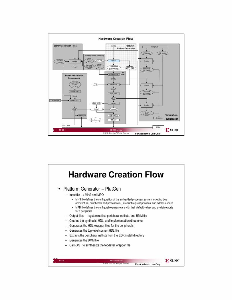
Hardware Creation Flow
• Platform Generator – PlatGen– Input file → MHS and MPD
• MHS file defines the configuration of the embedded processor system including bus
architecture, peripherals and processor(s), interrupt request priorities, and address space
• MPD file defines the configurable parameters with their default values and available ports
for a peripheral
– Output files → system netlist, peripheral netlists, and BMM file
– Creates the synthesis, HDL, and implementation directories
– Generates the HDL wrapper files for the peripherals
– Generates the top-level system HDL file
– Extracts the peripheral netlists from the EDK install directory
– Generates the BMM file
– Calls XST to synthesize the top-level wrapper file
12- 24 EDK Overview
13
© 2010 Xilinx, Inc. All Rights Reserved For Academic Use Only
Hardware Implementation Flow
Simulation
Generator
Hardware
Platform Generation
Library Generation
Embedded Software
Development
ISETools
IP Library or User Repository
MSS
LibGen
.a
Compiler (GCC)
.o, .a
Linker (GCC)
ELF
MHS
PlatGenDrivers,
MDDMPD, PAO
PcoreHDL
System andWrapper VHD
system.bmm
Synthesis (XST)
NGC
NGDBuildUCF
NGD
MAP, PAR
NCD
BitGensystem_bd.bmm
BITINIT
download.bit
iMPACT
system.bit
SimGen
BehavioralVHD Model
SimGen
StructuralVHD Model
SimGen
TimingVHD Model
Simulation
IP Models ISE Models
CompXLib
ApplicationSource.c, .h, .s
download.cmd
EDK SWLibraries
Libraries,OS, MLD
XMD, GDB
FPGAJTAG Cable
Linker Script
12- 25 EDK Overview
© 2010 Xilinx, Inc. All Rights Reserved For Academic Use Only
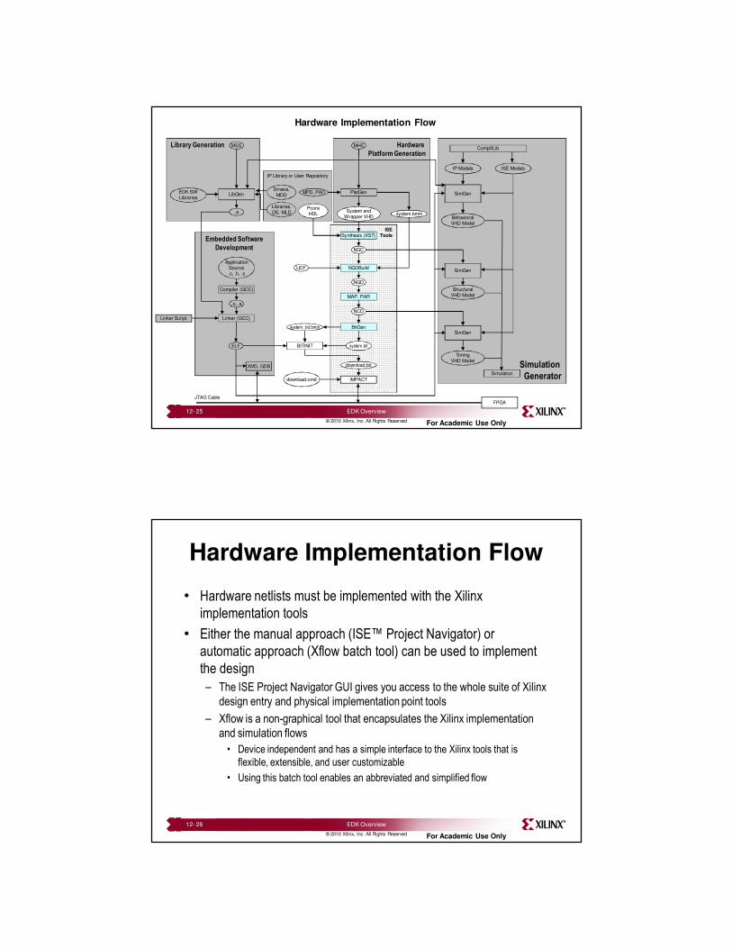
Hardware Implementation Flow
• Hardware netlists must be implemented with the Xilinx
implementation tools
• Either the manual approach (ISE™ Project Navigator) or
automatic approach (Xflow batch tool) can be used to implement
the design
– The ISE Project Navigator GUI gives you access to the whole suite of Xilinx
design entry and physical implementation point tools
– Xflow is a non-graphical tool that encapsulates the Xilinx implementation
and simulation flows
• Device independent and has a simple interface to the Xilinx tools that is
flexible, extensible, and user customizable
• Using this batch tool enables an abbreviated and simplified flow
12- 26 EDK Overview
14
© 2010 Xilinx, Inc. All Rights Reserved For Academic Use Only
Library Generation Flow
Simulation
Generator
Hardware
Platform Generation
Library Generation
Embedded Software
Development
ISETools
IP Library or User Repository
MSS
LibGen
.a
Compiler (GCC)
.o, .a
Linker (GCC)
ELF
MHS
PlatGenDrivers,
MDDMPD, PAO
PcoreHDL
System andWrapper VHD
system.bmm
Synthesis (XST)
NGC
NGDBuildUCF
NGD
MAP, PAR
NCD
BitGensystem_bd.bmm
BITINIT
download.bit
iMPACT
system.bit
SimGen
BehavioralVHD Model
SimGen
StructuralVHD Model
SimGen
TimingVHD Model
Simulation
IP Models ISE Models
CompXLib
ApplicationSource.c, .h, .s
download.cmd
EDK SWLibraries
Libraries,OS, MLD
XMD, GDB
FPGAJTAG Cable
Linker Script
12- 27 EDK Overview
© 2010 Xilinx, Inc. All Rights Reserved For Academic Use Only
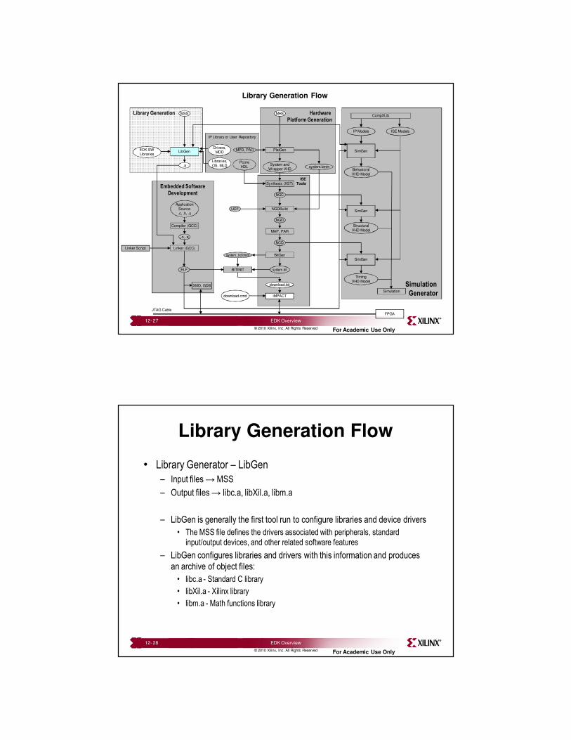
Library Generation Flow
• Library Generator – LibGen
– Input files → MSS
– Output files → libc.a, libXil.a, libm.a
– LibGen is generally the first tool run to configure libraries and device drivers
• The MSS file defines the drivers associated with peripherals, standard
input/output devices, and other related software features
– LibGen configures libraries and drivers with this information and produces
an archive of object files:
• libc.a - Standard C library
• libXil.a - Xilinx library
• libm.a - Math functions library
12- 28 EDK Overview
15
© 2010 Xilinx, Inc. All Rights Reserved For Academic Use Only
Software Application Flow
Simulation
Generator
Hardware
Platform Generation
Library Generation
Embedded Software
Development
ISETools
IP Library or User Repository
MSS
LibGen
.a
Compiler (GCC)
.o, .a
Linker (GCC)
ELF
MHS
PlatGenDrivers,
MDDMPD, PAO
PcoreHDL
System andWrapper VHD
system.bmm
Synthesis (XST)
NGC
NGDBuildUCF
NGD
MAP, PAR
NCD
BitGensystem_bd.bmm
BITINIT
download.bit
iMPACT
system.bit
SimGen
BehavioralVHD Model
SimGen
StructuralVHD Model
SimGen
TimingVHD Model
Simulation
IP Models ISE Models
CompXLib
ApplicationSource.c, .h, .s
download.cmd
EDK SWLibraries
Libraries,OS, MLD
XMD, GDB
FPGAJTAG Cable
Linker Script
12- 29 EDK Overview
© 2010 Xilinx, Inc. All Rights Reserved For Academic Use Only
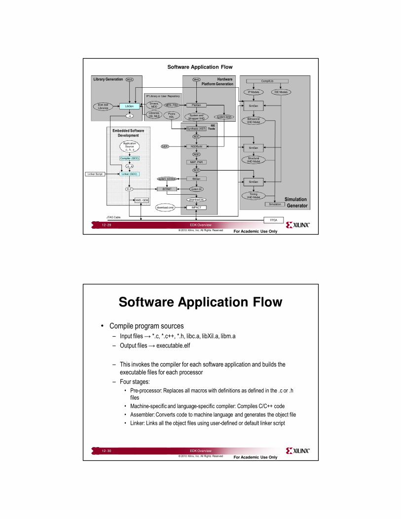
Software Application Flow
• Compile program sources
– Input files → *.c, *.c++, *.h, libc.a, libXil.a, libm.a
– Output files → executable.elf
– This invokes the compiler for each software application and builds the
executable files for each processor
– Four stages:
• Pre-processor: Replaces all macros with definitions as defined in the .c or .h
files
• Machine-specific and language-specific compiler: Compiles C/C++ code
• Assembler: Converts code to machine language and generates the object file
• Linker: Links all the object files using user-defined or default linker script
12- 30 EDK Overview
16
© 2010 Xilinx, Inc. All Rights Reserved For Academic Use Only
Merging Hardware and Software Flow
Simulation
Generator
Hardware
Platform Generation
Library Generation
Embedded Software
Development
ISETools
IP Library or User Repository
MSS
LibGen
.a
Compiler (GCC)
.o, .a
Linker (GCC)
ELF
MHS
PlatGenDrivers,
MDDMPD, PAO
PcoreHDL
System andWrapper VHD
system.bmm
Synthesis (XST)
NGC
NGDBuildUCF
NGD
MAP, PAR
NCD
BitGensystem_bd.bmm
BITINIT
download.bit
iMPACT
system.bit
SimGen
BehavioralVHD Model
SimGen
StructuralVHD Model
SimGen
TimingVHD Model
Simulation
IP Models ISE Models
CompXLib
ApplicationSource.c, .h, .s
download.cmd
EDK SWLibraries
Libraries,OS, MLD
XMD, GDB
FPGAJTAG Cable
Linker Script
12- 31 EDK Overview
© 2010 Xilinx, Inc. All Rights Reserved For Academic Use Only
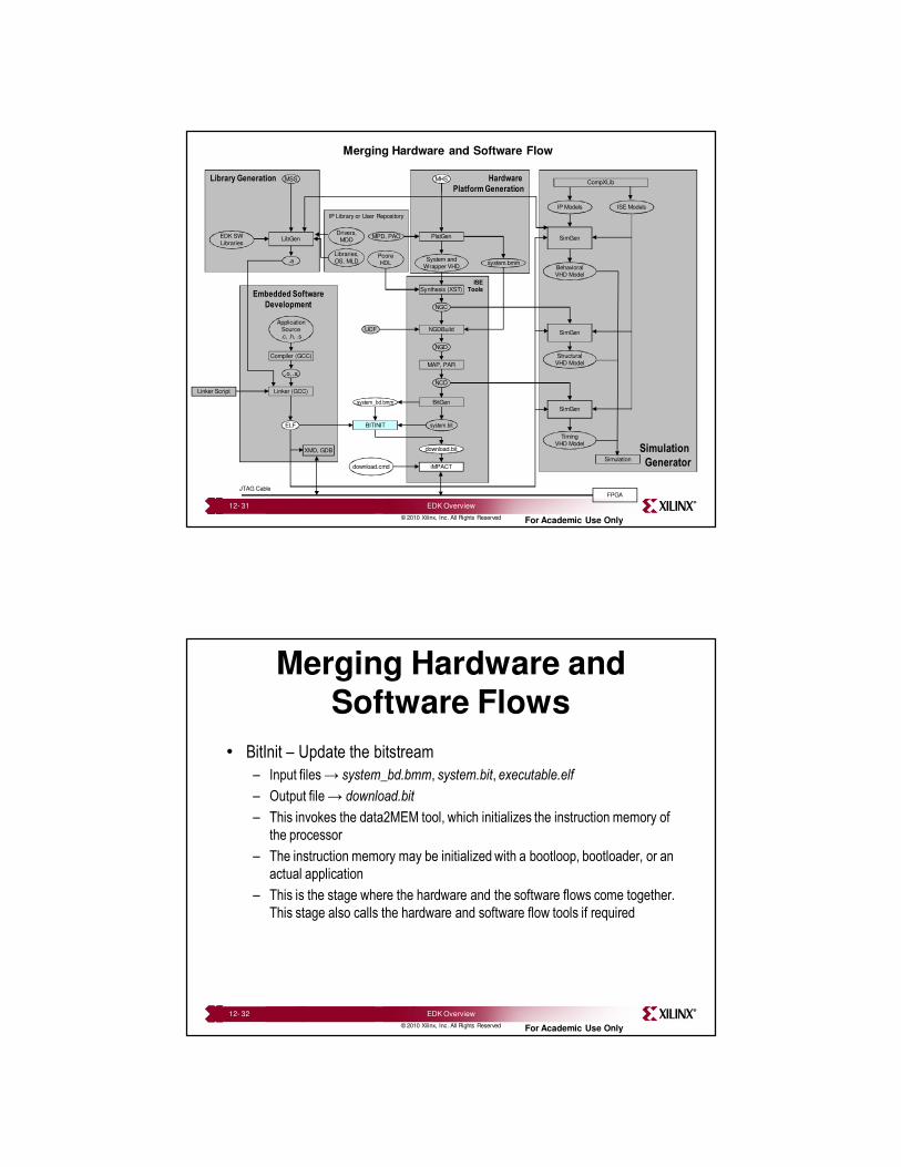
Merging Hardware and Software Flows
• BitInit – Update the bitstream
– Input files → system_bd.bmm, system.bit, executable.elf
– Output file → download.bit
– This invokes the data2MEM tool, which initializes the instruction memory of
the processor
– The instruction memory may be initialized with a bootloop, bootloader, or an
actual application
– This is the stage where the hardware and the software flows come together.
This stage also calls the hardware and software flow tools if required
12- 32 EDK Overview

17
© 2010 Xilinx, Inc. All Rights Reserved For Academic Use Only
Configuring the FPGA
• Download the bitstream
– Input file → download.bit
– This downloads the download.bit file onto the target board using the Xilinx
iMPACT tool in batch mode
– XPS uses the etc/download.cmd file for downloading the bitstream
• The download.cmd file contains information such as the type of cable is used
and the position of the FPGA in a JTAG chain
12- 33 EDK Overview
© 2010 Xilinx, Inc. All Rights Reserved For Academic Use Only
Outline
• Introduction
• EDK
– Overview of EDK
– Embedded Development Design Flow
– Embedded Project Management
• Supported Platforms
• Appendix: Project Files and Structure
12- 34 EDK Overview
18
© 2010 Xilinx, Inc. All Rights Reserved For Academic Use Only
XPS Platform Management
• Platform management tasks of XPS include:– Hardware Generation (PlatGen)
– Library and device driver configuration (LibGen)
– Simulation model generation (SimGen)
– Implementation (Xflow or ISE™)
– Compilation (GNU Compiler)
– Bitstream initialization (Data2MEM)
• For changing the system specification and software settings, XPS supports the following features and processes:– Add cores, edit core parameters, and make bus and port connections
through System Assembly view
– Generate and modify MSS file through Software Platform Settings
– Tool Flow Settings
– Tool Invocation
12- 35 EDK Overview
© 2010 Xilinx, Inc. All Rights Reserved For Academic Use Only
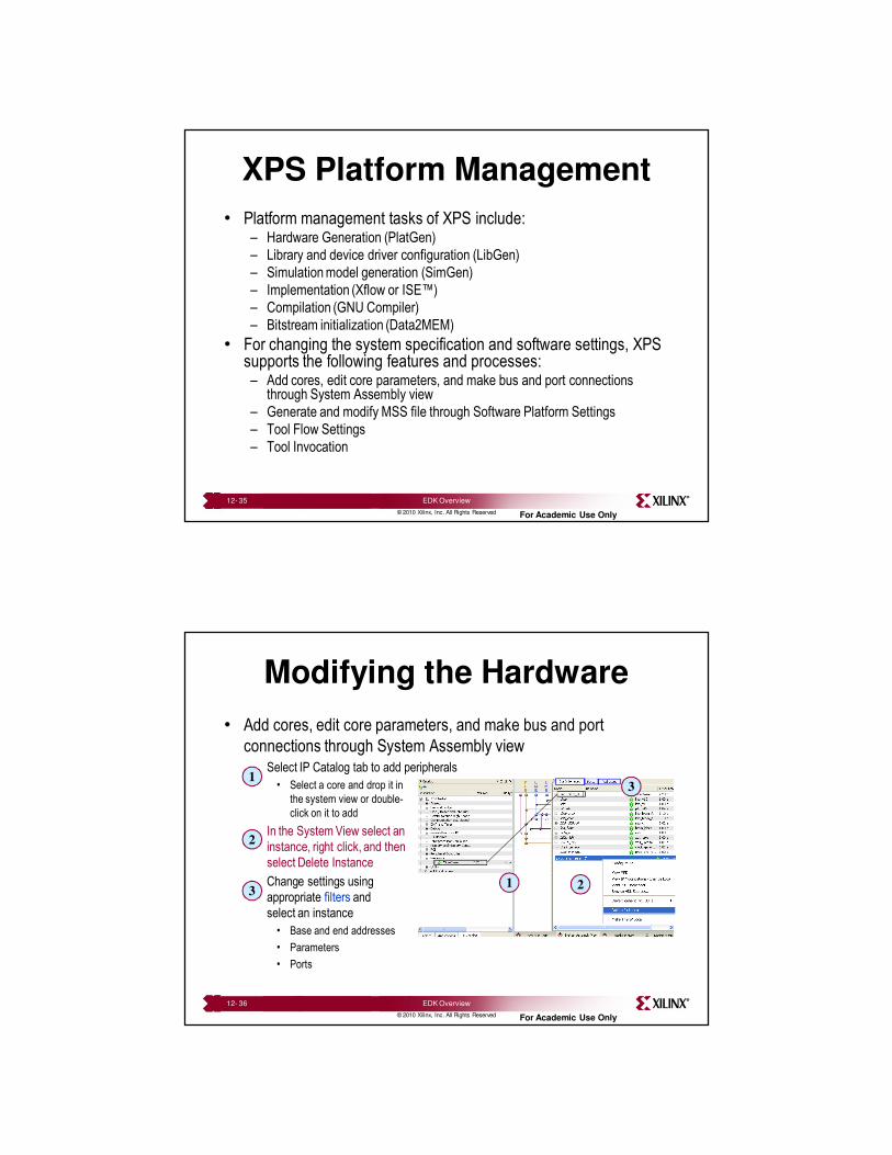
• Add cores, edit core parameters, and make bus and port
connections through System Assembly view– Select IP Catalog tab to add peripherals
• Select a core and drop it in
the system view or double-
click on it to add
– In the System View select an
instance, right click, and then
select Delete Instance
– Change settings using
appropriate filters and
select an instance
• Base and end addresses
• Parameters
• Ports
Modifying the Hardware
1
2
3
3
21
12- 36 EDK Overview

19
© 2010 Xilinx, Inc. All Rights Reserved For Academic Use Only
Setting Project Options
• XPS supports project options settings for:
– General tab
– Design Flow tab
12- 37 EDK Overview
© 2010 Xilinx, Inc. All Rights Reserved For Academic Use Only
Project OptionsGeneral Tab
• Set/Change Target Device
– Architecture
– Device Size
– Package
– Speed Grade
• Show dialog for evaluation cores
• Project Peripheral Repository– Specify the user repositories containing
custom pcores, drivers, Board Support
Packages (BSPs), and Software Services
• Custom Makefile Directory – Specify a custom make file to be used
instead of the make file generated by XPS.
The custom make file cannot have the same
name as XPS-generated make files:
<system>.make or <system>_incl.make.
12- 38 EDK Overview
20
© 2010 Xilinx, Inc. All Rights Reserved For Academic Use Only
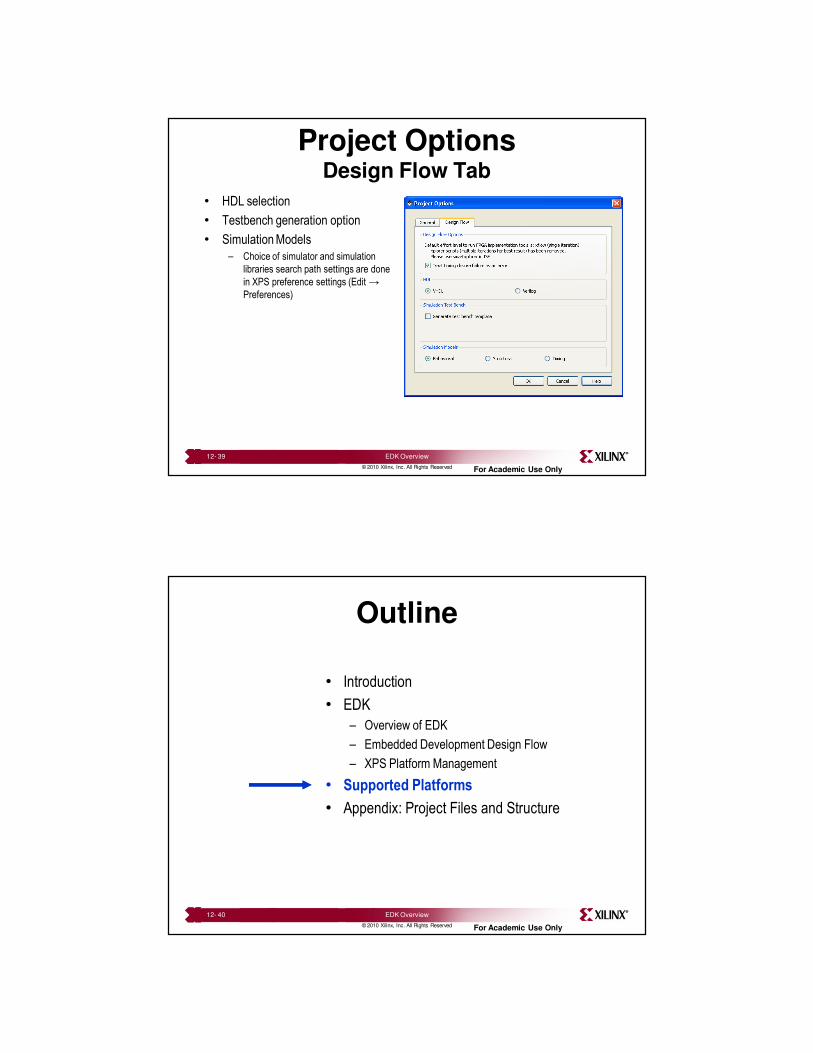
Project OptionsDesign Flow Tab
• HDL selection
• Testbench generation option
• Simulation Models
– Choice of simulator and simulation
libraries search path settings are done
in XPS preference settings (Edit →
Preferences)
12- 39 EDK Overview
© 2010 Xilinx, Inc. All Rights Reserved For Academic Use Only
Outline
• Introduction
• EDK
– Overview of EDK
– Embedded Development Design Flow
– XPS Platform Management
• Supported Platforms
• Appendix: Project Files and Structure
12- 40 EDK Overview
21
© 2010 Xilinx, Inc. All Rights Reserved For Academic Use Only
Supported Platforms
• Operating systems– Windows XP 32/64-bit SP2 Professional
– Windows Vista Business 32-bit
– Linux Red Hat Enterprise (4.0 and 5.0 32-bit/64-bit)
– SUSE Linux Enterprise 11, 32/64-bit
• FPGA families– Spartan-3E/3A/AN (MicroBlaze processor)
– Spartan-3A DSP (MicroBlaze processor)
– Spartan-6 (MicroBlaze processor)
– Virtex-4 FX (MicroBlaze and PowerPC processors) and LX/SX (MicroBlazeprocessor)
– Virtex-5 FXT (MicroBlaze and PowerPC processors) and LX/LXT/SXT (MicroBlaze processor)
– Virtex-6 FPGAs (MicroBlaze processor)
12- 41 EDK Overview
© 2010 Xilinx, Inc. All Rights Reserved For Academic Use Only
BSB-Supported Platforms
• A list of supported Xilinx hardware boards:– Spartan-3A/3AN Starter Kits
– Spartan-3E Starter Kit
– Spartan-3E 1600E MicroBlaze Development Kit
– Spartan-3A DSP 1800A Starter Kit
– Spartan-3A DSP 3400A
– Spartan-6 SP601, SP605
– Virtex-4 ML402, ML403, ML405, ML410
– Virtex-5 ML505, ML506,ML507,ML510
– Virtex-6 ML605
– Custom board
• Board definition (.xbd) files for third party boards can be downloaded from the board vendor web site– Links from the BSB wizard and Xilinx embedded Web page
12- 42 EDK Overview
22
© 2010 Xilinx, Inc. All Rights Reserved For Academic Use Only
Outline
• Introduction
• EDK
– Overview of EDK
– Embedded Development Design Flow
– XPS Platform Management
• Supported Platforms
• Appendix: Project Files and Structure
12- 43 EDK Overview
© 2010 Xilinx, Inc. All Rights Reserved For Academic Use Only
Project Directory Structure
project_directory
data - created by default upon project creation
etc - created by default upon project creation
pcores - created by default upon project creation
hdl - created during PlatGen
implementation - created during PlatGen
__xps - created by default upon project creation
ppc445_0/ppc405_0/microblaze_0 - created by default upon project creation
synthesis - created during PlatGen
12- 44 EDK Overview
23
© 2010 Xilinx, Inc. All Rights Reserved For Academic Use Only
Project Files and Structure
• ppc445_0/ppc405_0 / microblaze_0
– include
• *.h header files
– libsrc
• BSP, drivers, etc.
– lib
• libc.a file
• libm.a file
• libxil.a file
• boot.o file
– Code (default repository if user application is not defined)
• executable.elf file
12- 45 EDK Overview
© 2010 Xilinx, Inc. All Rights Reserved For Academic Use Only
Project Files and Structure
• pcores
– Peripheral IP files
• data
– system.ucf file
• Code or user-defined software application
– *.c / *.cpp, *.h files
• etc
– download.cmd file
– fast_runtime.opt file
– BSDL files
12- 46 EDK Overview
24
© 2010 Xilinx, Inc. All Rights Reserved For Academic Use Only
Project Files and Structure
• __xps – makefile
• synthesis– system.scr file
• HDL– system.[vhd|v], system_stub.[vhd|v]* file
– Peripheral_wrapper.[vhd|v] files
• implementation– peripheral_wrapper.ngc files
– system.ngc, system_stub.ngc* file
– system.bmm file
* files created if system is a submodule
12- 47 EDK Overview
© 2010 Xilinx, Inc. All Rights Reserved For Academic Use Only
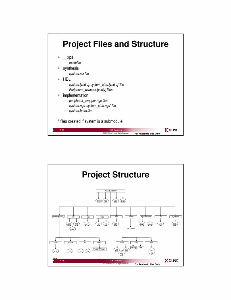
Project Structure
Project Directory
__xps pcores
<ip_name>
code
hdl devldata
verilog vhdl
MPD BBD
PAO
synthesisimplementation hdletcmblaze/ppc405_i
UCFCMD OPT
BSDL
MAKE
.H.C BMMNGC VHD SCR
PBD MSSMHS
data
include lib libsrccode
ELF .H .A .O
OS/BSP/DRIVER
OPT
ipwiz.l
og
12- 48 EDK Overview
25
© 2010 Xilinx, Inc. All Rights Reserved For Academic Use Only
Glossary of Tools and Files
• Some of the EDK tools:
– LibGen = Library Generator. Uses MSS file, copies device drivers source
files and generates software libraries for the defined system
– PlatGen = Platform Generator. Uses the MHS and MPD files to create an
implementation netlist of a bus-based sub-system
– SimGen = Simulation Generator. Uses MHS file to configure and generate a
simulation netlist pointing to various simulation model types, such as
SWIFT, BFM, netlist, RTL, etc.
12- 49 EDK Overview
© 2010 Xilinx, Inc. All Rights Reserved For Academic Use Only
Glossary of Tools and Files
• A few of the files the EDK tools generate:
– MDD = Microprocessor Driver Description
– MHS = Microprocessor Hardware Specification
– MPD = Microprocessor Peripheral Description
– MSS = Microprocessor Software Specification
– PAO = Peripheral Analyze Order
– BBD = Black Box Definition
– BMM = Block RAM Memory Map
12- 50 EDK Overview