mitigation of gps vulnerability - nist · wsts april 2013, san jose 1 april 2013 mitigation of gps...
TRANSCRIPT
WSTS April 2013, San Jose 1
APRIL 2013
MITIGATION OF GPS VULNERABILITY USING T IME TRANSFER OVER MICROWAVE SYSTEMS
Anurag Gupta Aviat Networks, Inc.
WSTS April 2013, San Jose
This presentation enumerates the critical infrastructure sectors that use GPS for Frequency or Time and are connected over one or more microwave links.
It touches up on how each of the sectors are likely to use the time/frequency
The mechanisms of transferring frequency and time over microwave links are covered and possible methods of backing up GPS are suggested
The level of accuracy in frequency/time transfer required for the backup mechanisms for some of the CIS sectors is also proposed.
Abstract
2
WSTS April 2013, San Jose
Critical Infrastructure Sectors
3
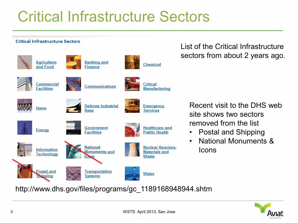
http://www.dhs.gov/files/programs/gc_1189168948944.shtm
List of the Critical Infrastructure sectors from about 2 years ago.
Recent visit to the DHS web site shows two sectors removed from the list • Postal and Shipping • National Monuments &
Icons
WSTS April 2013, San Jose
Critical Infrastructure Sectors
April 2013 4
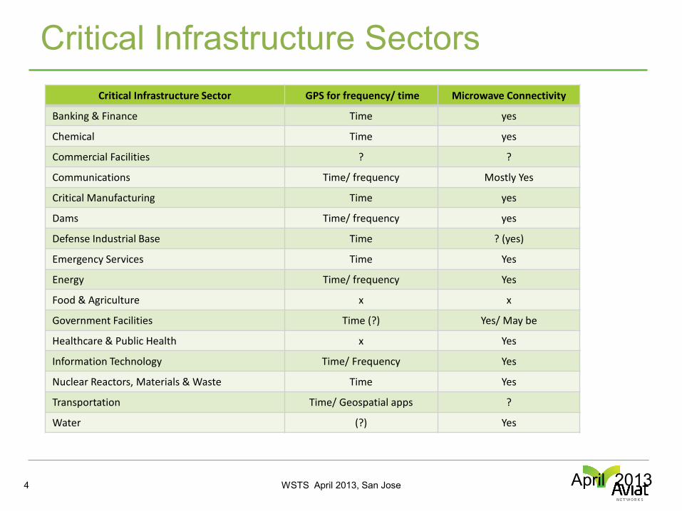
Critical Infrastructure Sector GPS for frequency/ time Microwave Connectivity
Banking & Finance Time yes
Chemical Time yes
Commercial Facilities ? ?
Communications Time/ frequency Mostly Yes
Critical Manufacturing Time yes
Dams Time/ frequency yes
Defense Industrial Base Time ? (yes)
Emergency Services Time Yes
Energy Time/ frequency Yes
Food & Agriculture x x
Government Facilities Time (?) Yes/ May be
Healthcare & Public Health x Yes
Information Technology Time/ Frequency Yes
Nuclear Reactors, Materials & Waste Time Yes
Transportation Time/ Geospatial apps ?
Water (?) Yes
WSTS April 2013, San Jose
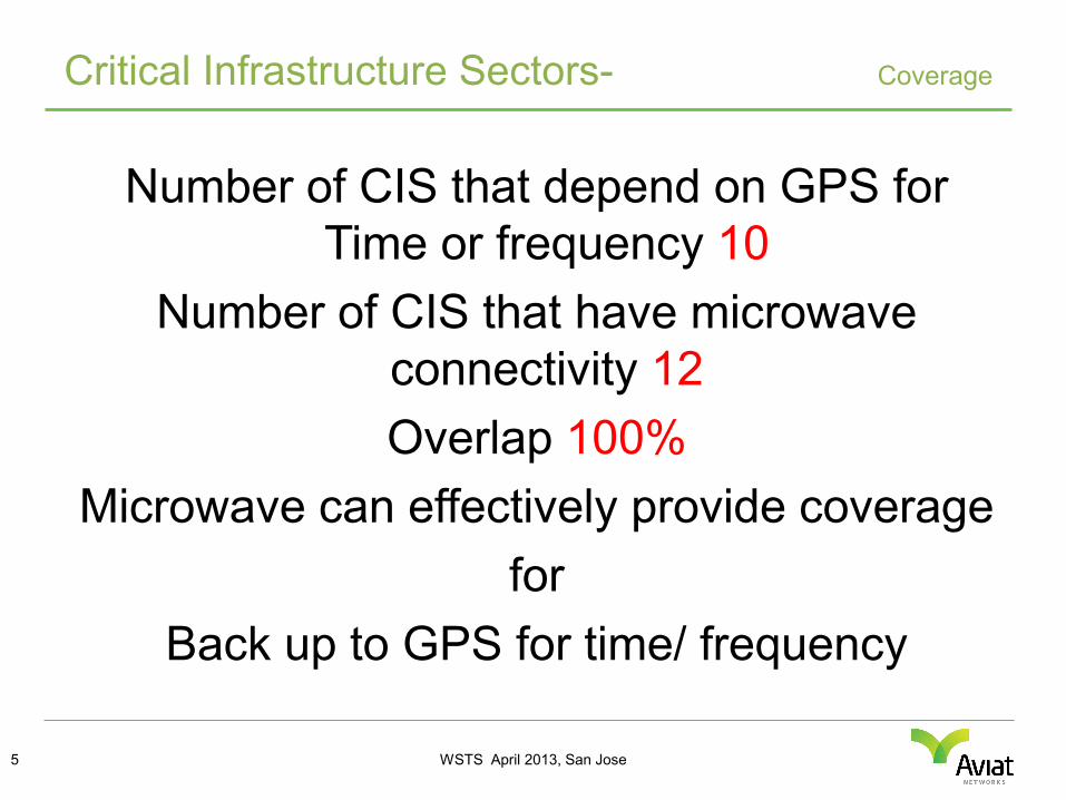
Number of CIS that depend on GPS for Time or frequency 10
Number of CIS that have microwave connectivity 12 Overlap 100%
Microwave can effectively provide coverage for
Back up to GPS for time/ frequency
Critical Infrastructure Sectors- Coverage
5
WSTS April 2013, San Jose
Typical Uses of Time/ Frequency
6
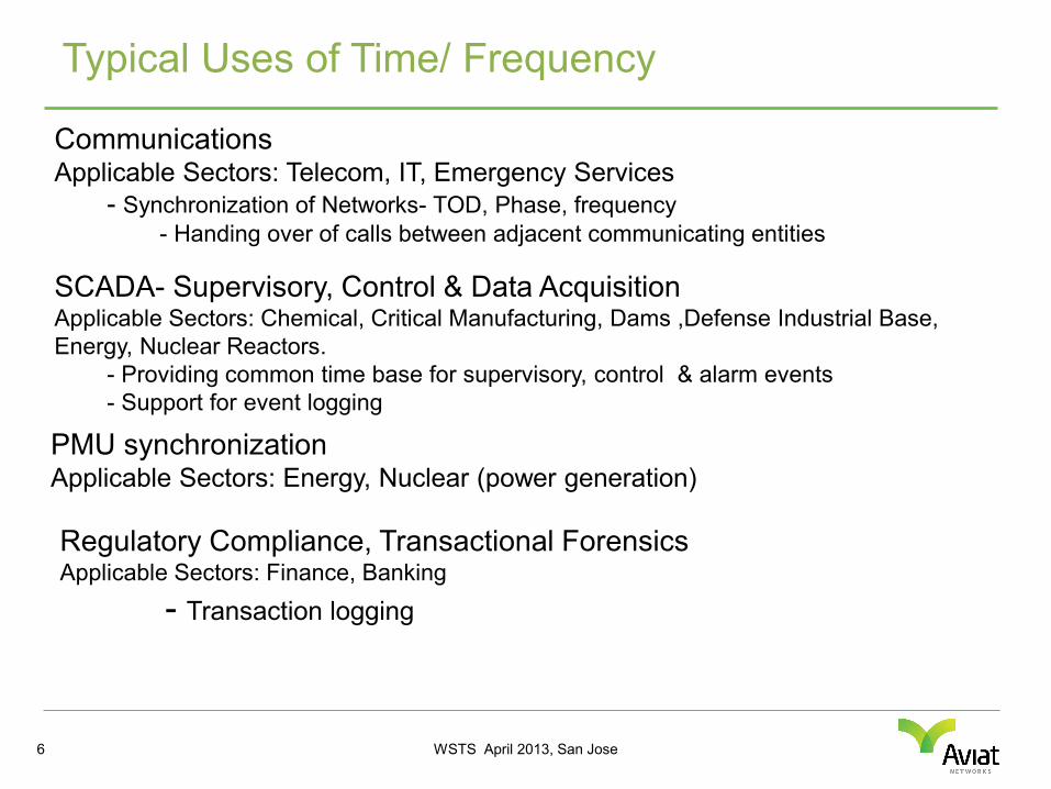
Communications Applicable Sectors: Telecom, IT, Emergency Services - Synchronization of Networks- TOD, Phase, frequency
- Handing over of calls between adjacent communicating entities SCADA- Supervisory, Control & Data Acquisition Applicable Sectors: Chemical, Critical Manufacturing, Dams ,Defense Industrial Base, Energy, Nuclear Reactors. - Providing common time base for supervisory, control & alarm events - Support for event logging
PMU synchronization Applicable Sectors: Energy, Nuclear (power generation) Regulatory Compliance, Transactional Forensics Applicable Sectors: Finance, Banking
- Transaction logging
WSTS April 2013, San Jose
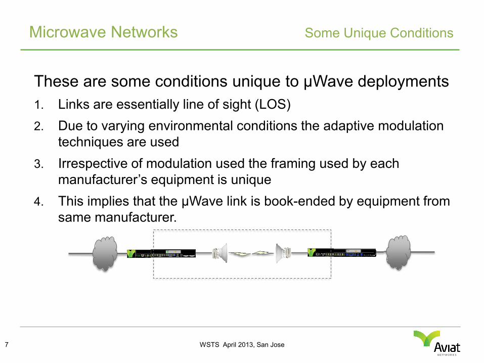
These are some conditions unique to μWave deployments 1. Links are essentially line of sight (LOS) 2. Due to varying environmental conditions the adaptive modulation
techniques are used 3. Irrespective of modulation used the framing used by each
manufacturer’s equipment is unique 4. This implies that the μWave link is book-ended by equipment from
same manufacturer.
Microwave Networks Some Unique Conditions
7
WSTS April 2013, San Jose
Microwave Modem Simplified block diagram
8
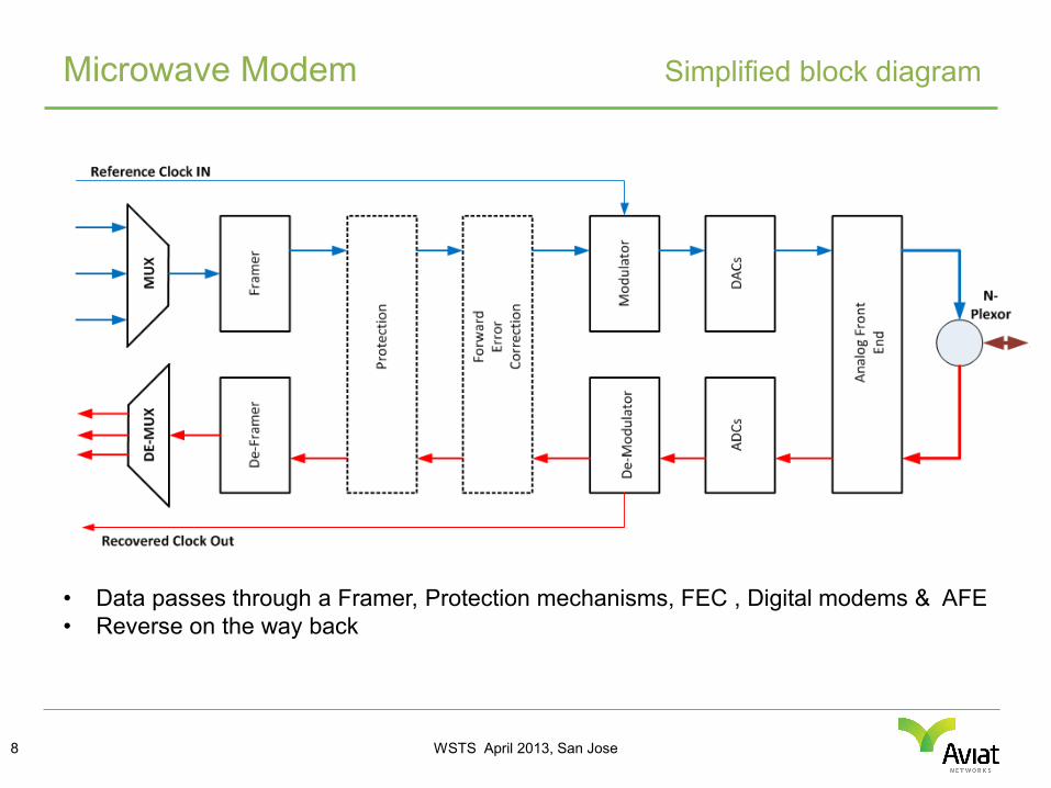
• Data passes through a Framer, Protection mechanisms, FEC , Digital modems & AFE • Reverse on the way back
WSTS April 2013, San Jose
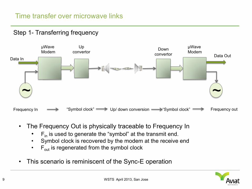
Step 1- Transferring frequency
Time transfer over microwave links
9
~
μWave Modem
μWave Modem
Up convertor Down
convertor Data In
Data Out
~
• The Frequency Out is physically traceable to Frequency In • Fin is used to generate the “symbol” at the transmit end. • Symbol clock is recovered by the modem at the receive end • Fout is regenerated from the symbol clock
• This scenario is reminiscent of the Sync-E operation
Frequency In Frequency out “Symbol clock” Up/ down conversion “Symbol clock”
WSTS April 2013, San Jose
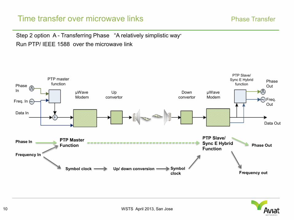
Step 2 option A - Transferring Phase “A relatively simplistic way”
Run PTP/ IEEE 1588 over the microwave link
Time transfer over microwave links Phase Transfer
10
Down convertor
μWave Modem
Up convertor
Data In
Data Out
Frequency In
Frequency out Symbol clock Up/ down conversion Symbol
clock
μWave Modem
PTP master function
PTP Slave/ Sync E Hybrid
function
Freq. In
Phase In
Phase Out
Freq. Out
Phase In PTP Master Function
PTP Slave/ Sync E Hybrid Function
Phase Out
WSTS April 2013, San Jose
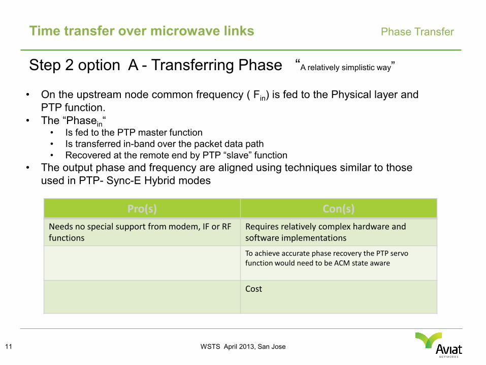
Step 2 option A - Transferring Phase “A relatively simplistic way”
Time transfer over microwave links Phase Transfer
11
• On the upstream node common frequency ( Fin) is fed to the Physical layer and PTP function.
• The “Phasein“ • Is fed to the PTP master function • Is transferred in-band over the packet data path • Recovered at the remote end by PTP “slave” function
• The output phase and frequency are aligned using techniques similar to those used in PTP- Sync-E Hybrid modes
Pro(s) Con(s) Needs no special support from modem, IF or RF functions
Requires relatively complex hardware and software implementations
To achieve accurate phase recovery the PTP servo function would need to be ACM state aware
Cost
WSTS April 2013, San Jose
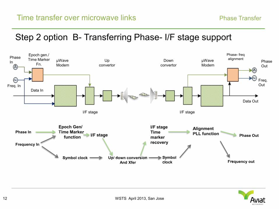
Step 2 option B- Transferring Phase- I/F stage support
Time transfer over microwave links Phase Transfer
12
Down convertor
μWave Modem
Up convertor
Data In
Data Out
μWave Modem
Epoch gen./ Time Marker
Fn.
Phase- freq alignment
Freq. In
Phase In Phase
Out
Freq. Out
Frequency In
Frequency out Symbol clock Up/ down conversion
And Xfer Symbol clock
Phase In Epoch Gen/ Time Marker
function
Alignment PLL function Phase Out I/F stage
I/F stage Time marker recovery
I/F stage I/F stage

WSTS April 2013, San Jose
Step 2 option B- Transferring Phase- I/F stage support
Time transfer over microwave links Phase Transfer
13
• On the upstream node common frequency ( Fin) is fed to the Physical layer and Time marker/ epoch generation function.
• The Phasein • is fed to the (above) time marker function • The time marker is used to generate “time marker” event at the I/F stage • The event is Recovered at the remote I/F stage
• The output phase and frequency are aligned using standard DPLL techniques.
Pro(s) Con(s) Cost would be lower than option A Requires Time marker event generation and
recovery support at the I/F stage in microwave modems
Relatively straight forward logic implementable in simple CPLD/ FPGA
WSTS April 2013, San Jose
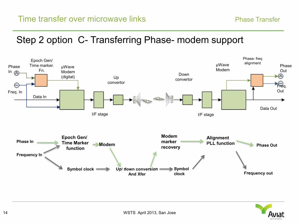
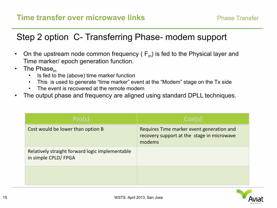
Step 2 option C- Transferring Phase- modem support
Time transfer over microwave links Phase Transfer
14
Down convertor
μWave Modem (digital) Up
convertor
Data In
Data Out
μWave Modem
Epoch Gen/ Time marker.
Fn.
Phase- freq alignment
Freq. In
Phase In
Phase Out
Freq. Out
Frequency In
Frequency out Symbol clock Up/ down conversion
And Xfer Symbol clock
Phase In Alignment PLL function Phase Out Modem
Modemmarker recovery
I/F stage I/F stage
Epoch Gen/ Time Marker
function
WSTS April 2013, San Jose
Step 2 option C- Transferring Phase- modem support
Time transfer over microwave links Phase Transfer
15
• On the upstream node common frequency ( Fin) is fed to the Physical layer and Time marker/ epoch generation function.
• The Phasein • Is fed to the (above) time marker function • This is used to generate “time marker” event at the “Modem” stage on the Tx side • The event is recovered at the remote modem
• The output phase and frequency are aligned using standard DPLL techniques.
Pro(s) Con(s) Cost would be lower than option B Requires Time marker event generation and
recovery support at the stage in microwave modems
Relatively straight forward logic implementable in simple CPLD/ FPGA
WSTS April 2013, San Jose
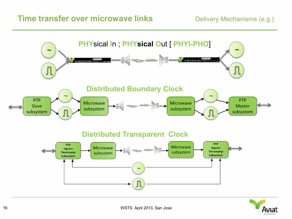
Time transfer over microwave links Delivery Mechanisms (e.g.)
16
~ ~ PHYsical In ; PHYsical Out [ PHYI-PHO]
Distributed Boundary Clock
Distributed Transparent Clock
WSTS April 2013, San Jose
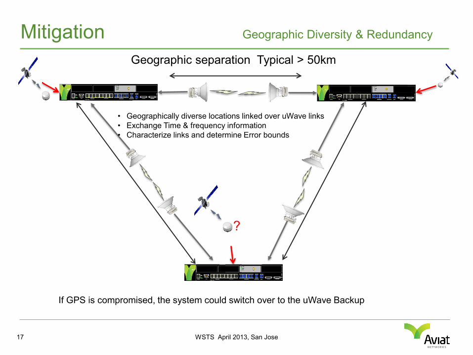
Mitigation Geographic Diversity & Redundancy
Geographic separation Typical > 50km
• Geographically diverse locations linked over uWave links • Exchange Time & frequency information • Characterize links and determine Error bounds
If GPS is compromised, the system could switch over to the uWave Backup
?
17
WSTS April 2013, San Jose
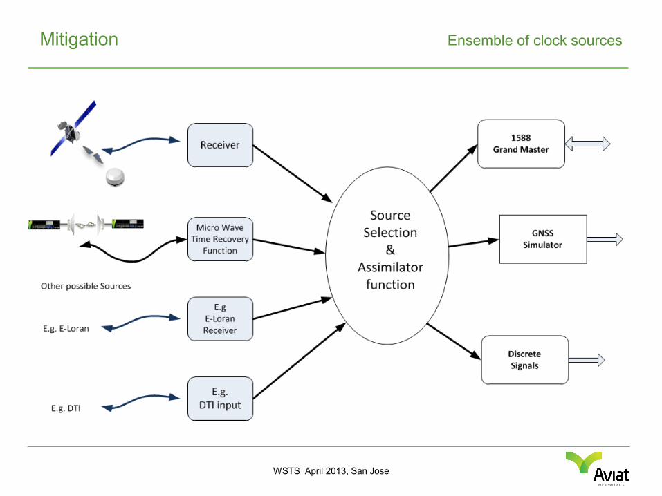
Mitigation Ensemble of clock sources
WSTS April 2013, San Jose
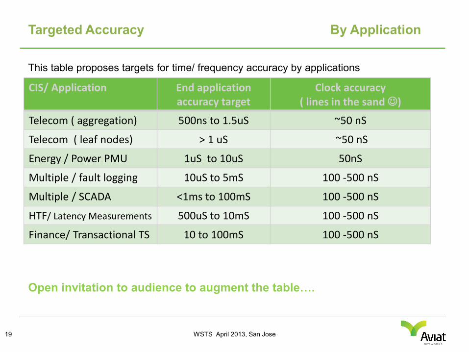
Targeted Accuracy By Application
19
CIS/ Application End application accuracy target
Clock accuracy ( lines in the sand )
Telecom ( aggregation) 500ns to 1.5uS ~50 nS
Telecom ( leaf nodes) > 1 uS ~50 nS
Energy / Power PMU 1uS to 10uS 50nS
Multiple / fault logging 10uS to 5mS 100 -500 nS
Multiple / SCADA <1ms to 100mS 100 -500 nS
HTF/ Latency Measurements 500uS to 10mS 100 -500 nS
Finance/ Transactional TS 10 to 100mS 100 -500 nS
This table proposes targets for time/ frequency accuracy by applications
Open invitation to audience to augment the table….
WSTS April 2013, San Jose
Summary & Conclusion
20
• Most entities in CIS use GNSS for synchronization ………………use Microwave for communication
• Microwave links with timing enhancements ……….can provide reliable back up to GPS for synchronization applications

WSTS April 2013, San Jose
QUESTIONS?
THANK YOU FOR YOUR ATTENTION…….
Anurag Gupta +1-408-567-7286 Email: [email protected]