microsoft exchange 2013 deployment guide
DESCRIPTION
Microsoft Exchange 2013 Deployment GuideTRANSCRIPT

7/18/2019 Microsoft Exchange 2013 Deployment Guide
http://slidepdf.com/reader/full/microsoft-exchange-2013-deployment-guide 1/49
oad Balancing Microsoft Exchange 2013
Deployment Guide
rev. 1.1.6
Copyright © 2002 – 2015 Loadbalancer.org, Inc.

7/18/2019 Microsoft Exchange 2013 Deployment Guide
http://slidepdf.com/reader/full/microsoft-exchange-2013-deployment-guide 2/49
Table of Contents
About this Guide............................................................................................................................................................4Appliances Supported..................................................................................................................................................4Microsoft Exchange Software Versions Supported...........................................................................................4Loadbalancer.org Software Versions Supported................................................................................................4
Exchange Server 2013..................................................................................................................................................5Exchange 2013 Server Roles......................................................................................................................................5Load Balancing Exchange 2013................................................................................................................................6Load Balancing & HA Requirements..................................................................................................................................6Client Access Array.............................................................................................................................................................6Database Availability Group (DAG)................................................................................................................................6
Persistence (aka Server Affinity)...........................................................................................................................................6Port Requirements...................................................................................................................................................................6HTTPS Namespaces & IP addresses....................................................................................................................................7
Deployment Overview.................................................................................................................................................8Virtual Service (VIP) Requirements......................................................................................................................................8Clustered Pair Configuration for HA..................................................................................................................................8
Load Balancer Deployment Methods.....................................................................................................................9Layer 4..........................................................................................................................................................................................9Direct Server Return (DR Mode).....................................................................................................................................9Network Address Translation (NAT Mode)................................................................................................................10
Layer 7 SNAT Mode................................................................................................................................................................11Our Recommendation.........................................................................................................................................................12Helping you Choose........................................................................................................................................................12
Exchange 2013 Configuration for Load Balancing..........................................................................................14External Access Domain......................................................................................................................................................14Virtual Directories..................................................................................................................................................................14Outlook Anywhere................................................................................................................................................................15Autodiscover............................................................................................................................................................................15Certificates................................................................................................................................................................................17Send & Receive Connectors...............................................................................................................................................17Adding Connectors..........................................................................................................................................................18
IIS Restart (Important step!)................................................................................................................................................18Exchange Server Configuration Steps (Depends on Load balancing Method)..................................................18DR Mode – Solve the ARP problem............................................................................................................................18NAT Mode – Set the Exchange Servers Default Gateway....................................................................................18SNAT Mode.........................................................................................................................................................................18
Loadbalancer.org Appliance – the Basics...........................................................................................................19Network Configuration........................................................................................................................................................19Accessing the Web User Interface (WUI).......................................................................................................................20
Appliance Configuration for Exchange 2013 – Using DR Mode.................................................................21Configure VIP1 – CAS Role HTTPS Services............................................................................................................21a) Setting up the Virtual Service.............................................................................................................................21b) Setting up the Real Servers.................................................................................................................................22
Configure VIP2 – CAS Role IMAP4 / POP3 Services.............................................................................................23a) Setting up the Virtual Service.............................................................................................................................23b) Setting up the Real Servers................................................................................................................................24
Configure VIP3 – CAS Role SMTP Services..............................................................................................................25a) Setting up the Virtual Service.............................................................................................................................25
b) Setting up the Real Servers................................................................................................................................26Configure HTTP to HTTPS OWA Redirect................................................................................................................26
Appliance Configuring for Exchange 2013 – Using NAT Mode..................................................................27Configure VIP1 – CAS Role HTTPS Services............................................................................................................27

7/18/2019 Microsoft Exchange 2013 Deployment Guide
http://slidepdf.com/reader/full/microsoft-exchange-2013-deployment-guide 3/49
a) Setting up the Virtual Service.............................................................................................................................27b) Setting up the Real Servers................................................................................................................................28
Configure VIP2 – CAS Role IMAP4 / POP3 Services.............................................................................................29a) Setting up the Virtual Service.............................................................................................................................29b) Setting up the Real Servers................................................................................................................................30
Configure VIP3 – CAS Role SMTP Services..............................................................................................................31a) Setting up the Virtual Service.............................................................................................................................31
b) Setting up the Real Servers.................................................................................................................................32Configure HTTP to HTTPS OWA Redirect................................................................................................................32
Appliance Configuring for Exchange 2013 – Using SNAT mode...............................................................33Configure Layer 7 Global Settings..............................................................................................................................33Configure VIP1 – CAS Role HTTPS Services............................................................................................................34a) Setting up the Virtual Service.............................................................................................................................34b) Setting up the Real Servers.................................................................................................................................35
Configure VIP2 – CAS Role IMAP4 / POP3 Services.............................................................................................36a) Setting up the Virtual Service.............................................................................................................................36b) Setting up the Real Servers.................................................................................................................................37
Configure VIP3 – CAS Role SMTP Services..............................................................................................................38a) Setting up the Virtual Service.............................................................................................................................38
b) Setting up the Real Servers................................................................................................................................39Configure HTTP to HTTPS OWA Redirect................................................................................................................39Finalizing the Configuration.........................................................................................................................................39
Testing & Verification.................................................................................................................................................40Useful Exchange 2013 & Other Microsoft Tools.........................................................................................................40Testing Mailflow...............................................................................................................................................................40Testing SMTP using Telnet.............................................................................................................................................41Microsoft Testing Tool....................................................................................................................................................42
Useful Appliance based Tools & Features......................................................................................................................42Using System Overview..................................................................................................................................................42Layer 4 Status Report......................................................................................................................................................43Layer 7 Statistics Report.................................................................................................................................................43
Appliance Logs..................................................................................................................................................................43Technical Support.......................................................................................................................................................44Conclusion....................................................................................................................................................................44Appendix........................................................................................................................................................................451 – Enabling full Transparency using Tproxy (applies to Layer 7 SNAT mode)..................................................452 – Limiting inbound SMTP Connections using Firewall Rules (applies to Layer 7 SNAT mode)................463 – Using a Layer 4 Virtual Service for SMTP................................................................................................................474 – Configuring an HTTP to HTTPS redirect for OWA..............................................................................................475 – Clustered Pair Configuration – Adding a Slave Unit...........................................................................................486 – Company Contact Information.................................................................................................................................49

7/18/2019 Microsoft Exchange 2013 Deployment Guide
http://slidepdf.com/reader/full/microsoft-exchange-2013-deployment-guide 4/49
About this Guide
This guide details the configuration of Loadbalancer.org appliances for deployment with MicrosoftExchange 2013. It includes details of ports/services that must be load balanced, topology considerationsfor the various Exchange 2013 server roles and also steps on how to configure the appliances.
For an introduction on setting up the appliance as well as more technical information, please also refer toour quick-start guides and full administration manuals which are available at the following links:
Version 7 Documentation
v7.x Quickstart Guide :http://www.loadbalancer.org/pdf/quickstartguideLBv7.pdf
v7.x Administration Manual : http://www.loadbalancer.org/pdf/loadbalanceradministrationv7.pdf
Version 8 Documentation
v8.x Quickstart Guide :http://www.loadbalancer.org/pdf/quickstartguideLBv8.pdf
v8.x Administration Manual : http://www.loadbalancer.org/pdf/loadbalanceradministrationv8.pdf
Appliances Supported
All our products can be used with Exchange 2013. The complete list of models is shown below:
Discontinued Models Current Models *
Enterprise R16 Enterprise R20
Enterprise VA R16 Enterprise MAX
Enterprise VA Enterprise 10G
Enterprise R320Enterprise VA R20
Enterprise VA MAX
Enterprise AWS **
Enterprise AZURE **
* For full specifications of these models please refer to: http://www.loadbalancer.org/products
** Some features may not be supported, please check with Loadbalancer.org support
Microsoft Exchange Software Versions Supported
• Microsoft Exchange 2013 CU2 (15.0.712.24) and later
oadbalancer.org Software Versions Supported
• v7.5 and later
N.B. this guide includes configuration steps for v7.6 & later. For older versions of the applianceplease contact Loadbalancer.org sales or support
4

7/18/2019 Microsoft Exchange 2013 Deployment Guide
http://slidepdf.com/reader/full/microsoft-exchange-2013-deployment-guide 5/49
Exchange Server 2013
Exchange 2013 is Microsoft's latest enterprise level messaging and collaboration server. Exchange 2013 hasbeen designed for simplicity of scale, hardware utilization, and failure isolation. This has greatly simplifiedboth the deployment process and the implementation of a load balancer.
Exchange 2013 Server Roles
Exchange 2013 has been consolidated into two roles, these are: theClient Access Server role and theMailbox Serverrole.
The functionality of the Hub Transport server role has split between the CAS role (theFront End TransportService) and the Mailbox Server role (theTransport Service and theMailbox Transport Service).
The Edge Transport server role has been removed.
Role Purpose
Client Access Server The Client Access Server role is comprised of three components, clientprotocols, SMTP, and a UM Call Router. The CAS role is a thin, protocol
session stateless server that is organized into a load balancedconfiguration. Unlike previous versions, session affinity is not required atthe load balancer. This is because logic now exists in CAS to authenticatethe request, and then route the request to the Mailbox server that hoststhe active copy of the mailbox database.
N.B. A number of issues have been seen with IOS-7 on the iPhone whenused with ActiveSync. Upgrading to IOS-8 resolved these issues.
Mailbox Server The Mailbox Server role now hosts all the components and/or protocolsthat process, render and store the data. No clients will ever connectdirectly to the Mailbox server role; all client connections are handled bythe Client Access Server role. Mailbox Servers can be added to a Database
Availability Group, thereby forming a high available unit that can bedeployed in one or more datacenters.
CAS Array Object
This concept has been removed and there is no longer any need to define a CAS array object.
Client Access Protocols
Outlook clients no longer use RPC to access their mailbox. This is now handled only by RPC over HTTPS(aka Outlook Anywhere). Native RPC is only used for server to sever communication. POP3 and IMAP4
continue to be supported as with previous versions.
External SMTP Mail flow
External SMTP communication is now handled by theFront End Transport Service on the CAS role.
Exchange Administration
The Exchange Admin Center (EAC) is the new web-based management console in Microsoft ExchangeServer 2013. The EAC replaces the Exchange Management Console (EMC) and the Exchange Control Panel(ECP), which were the two interfaces used to manage Exchange Server 2010. Note that “ECP” is still thename of the virtual directory used by the EAC.
5

7/18/2019 Microsoft Exchange 2013 Deployment Guide
http://slidepdf.com/reader/full/microsoft-exchange-2013-deployment-guide 6/49
oad Balancing Exchange 2013
Load Balancing & HA Requirements
In Exchange Server 2013, there are two basic building blocks – the Client Access Array and the DatabaseAvailability Group (DAG). Each provides a unit of high availability and fault tolerance that are decoupled
from one another. Multiple Client Access Servers make up the Client Access Array, while multiple MailboxServers form the DAG.
Client Access Array
As mentioned earlier, the 2010 concept of a CAS Array no longer exists. In 2013, a Client Access Array issimply a group of two or more Client Access Servers. The load balancer then enables resilience and HA.
Database Availability Group (DAG)
A DAG is a group of up to 16 Mailbox Servers that hosts a set of databases and provides automaticdatabase-level recovery from failures that affect individual servers or databases.
NOTE: DAG's utilize Microsoft Clustering Services which cannot be enabled on the sameserver as Microsoft Network Load Balancing (NLB). Therefore, using Microsoft NLB is not anoption in this case. Using a Loadbalancer.org hardware or virtual appliance provides an idealsolution.
Persistence (aka Server Affinity)Due to Exchange 2013's new architecture, all sessions to the CAS servers are stateless and thereforepersistence/affinity is no longer required on the load balancer.
Port Requirements
The following table shows the port list that must be load balanced. Some services such as IMAP4 or POP3may not be used in your environment.
TCP Port Role(s) Uses
25 CAS Inbound SMTP
110 CAS POP3 clients
143 CAS IMAP4 clients
443 CAS HTTPS (Outlook Web App, AutoDiscovery, Web Services, ActiveSync,Outlook Anywhere, Offline Address Book, Exchange AdministrationCenter)
993 CAS Secure IMAP4 clients
995 CAS Secure POP3 clients
6
7/18/2019 Microsoft Exchange 2013 Deployment Guide
http://slidepdf.com/reader/full/microsoft-exchange-2013-deployment-guide 7/49
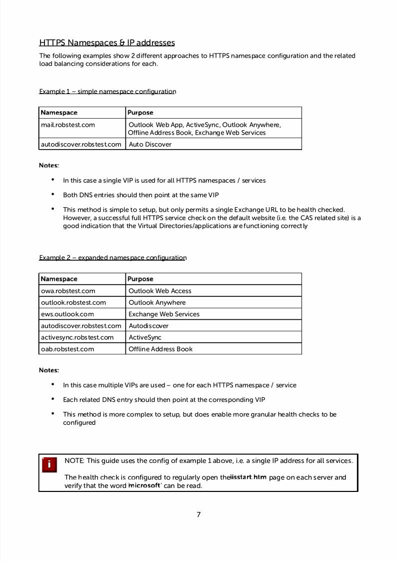
HTTPS Namespaces & IP addresses
The following examples show 2 different approaches to HTTPS namespace configuration and the relatedload balancing considerations for each.
Example 1 – simple namespace configuration
Namespace Purpose
mail.robstest.com Outlook Web App, ActiveSync, Outlook Anywhere,Offline Address Book, Exchange Web Services
autodiscover.robstest.com Auto Discover
Notes:
• In this case a single VIP is used for all HTTPS namespaces / services
• Both DNS entries should then point at the same VIP
• This method is simple to setup, but only permits a single Exchange URL to be health checked.However, a successful full HTTPS service check on the default website (i.e. the CAS related site) is agood indication that the Virtual Directories/applications are functioning correctly
Example 2 – expanded namespace configuration
Namespace Purpose
owa.robstest.com Outlook Web Access
outlook.robstest.com Outlook Anywhere
ews.outlook.com Exchange Web Services
autodiscover.robstest.com Autodiscover
activesync.robstest.com ActiveSync
oab.robstest.com Offline Address Book
Notes:
• In this case multiple VIPs are used – one for each HTTPS namespace / service
• Each related DNS entry should then point at the corresponding VIP
• This method is more complex to setup, but does enable more granular health checks to beconfigured
NOTE: This guide uses the config of example 1 above, i.e. a single IP address for all services.
The health check is configured to regularly open theiisstart.htm page on each server andverify that the word 'microsoft' can be read.
7

7/18/2019 Microsoft Exchange 2013 Deployment Guide
http://slidepdf.com/reader/full/microsoft-exchange-2013-deployment-guide 8/49
Deployment Overview
There are multiple ways to deploy Exchange, but in this example two servers are used. Each server hoststhe CAS & Mailbox roles in a DAG configuration. This provides high availability and uses a minimumnumber of Exchange Servers.
Clients then connect to the Virtual Services (VIPs) on the load balancer rather than connecting directly to aone of the real servers. These connections are then load balanced across the back-end servers todistribute the load according to the load balancing algorithm selected.
The load balancer can be deployed as a single unit, although Loadbalancer.org stronglyrecommends a clustered pair for resilience & high availability.
Virtual Service (VIP) Requirements
To provide load balancing and HA for Exchange, the following VIPs are required:
• HTTPS & HTTP (the HTTP VIP is only required for redirecting to HTTPS)
• SMTP
Optionally, additional VIPs may be required for the following services:
• IMAP4
• POP3
N.B. IMAP4 and POP3 are not typically used. Therefore these VIPs are not generally required.
Clustered Pair Configuration for HA
In this guide a single unit is deployed first, adding a secondary slave unit is covered in section 5 of the
Appendix.
8
CAS/MBOX 1LoadBalancer
(single unit
or clusteredpair)
InboundReuests
!I"(s)
CAS/MBOX #
$A%

7/18/2019 Microsoft Exchange 2013 Deployment Guide
http://slidepdf.com/reader/full/microsoft-exchange-2013-deployment-guide 9/49
oad Balancer Deployment Methods
The load balancer can be deployed in one of 3 fundamental ways, these are described below.
Layer 4
Two Layer 4 methods are available – 'DR Mode' and 'NAT Mode'.
Direct Server Return (DR Mode)
In this mode, traffic from the client to the Exchange Servers passes via the load balancer, return trafficpasses directly back to the client which maximizes performance. DR mode works by changing thedestination MAC address of the incoming packet on the fly, which is very fast. This mode is transparent bydefault meaning that the Exchange Servers see the real client IP address and not the IP address of the loadbalancer.
Notes:
• One-arm DR mode works by changing the destination MAC address of the incoming packet on thefly which is very fast
• The 'ARP problem' must be solved on each Exchange Server (please refer to page 18)
• The VIP and RIPs must be in the same switch fabric / logical network. They can be on differentsubnets, provided there are no router hops between them. If multiple subnets are used, an IPaddress in each subnet must be defined on the load balancer
• Layer 4 DR mode is transparent, i.e. servers will log the source IP address of the client
• The source IP address of reply packets is the VIP address
9
!I"(s)
CAS/MBOX1
CAS/MBOX#
LoadBalancer
One&ar' / single subnet
outbound responsesgo bac to te clientdirectl* b*passingte load balancer
inboundreuests
RIP1 RIP2
loadbalancedreuests

7/18/2019 Microsoft Exchange 2013 Deployment Guide
http://slidepdf.com/reader/full/microsoft-exchange-2013-deployment-guide 10/49
Network Address Translation (NAT Mode)
This modes requires the implementation of a two–arm infrastructure with an internal and external subnetto carry out the translation (the same way a firewall works). The real servers (i.e. the Exchange Servers)must have their default gateway configured to point at the load balancer. It also offers high performanceand like DR mode is transparent by default.
Notes:
• In two–arm NAT mode the load balancer translates all requests from the external Virtual Service tothe internal Exchange Servers
• Normally eth0 is used for theinternalnetwork and eth1 is used for theexternal network althoughthis is not mandatory. If the Exchange Servers require Internet access, Autonat should be enabledusing the WUI option:Edit Configuration > Layer 4 – Advanced Configuration, select the externalinterface
• The default gateway on each Exchange Server must be an IP address on the load balancer. Thisshould be a floating IP address to allow failover to the slave device
• Layer 4 NAT mode is transparent, i.e. servers will log the source IP address of the client
• The source IP address of the reply packets is the VIP address
10
LoadBalancer
!I"(s)
Subnet 1 Subnet #
CAS/MBOX#
CAS/MBOX1
+,o&ar' / dual subnets
de-aultgate,a*
replies 'ust gobac to te client
.ia te loadbalancer
inbound reuests /outbound responses
RIP1
RIP2
loadbalancedreuests

7/18/2019 Microsoft Exchange 2013 Deployment Guide
http://slidepdf.com/reader/full/microsoft-exchange-2013-deployment-guide 11/49
Layer 7 SNAT Mode
Layer 7 load balancing uses a proxy (HAProxy) at the application layer. Inbound requests are terminated onthe load balancer, and HAProxy generates a new request to the chosen real server. As a result, Layer 7 is aslower technique than DR or NAT mode at Layer 4. Layer 7 is generally chosen when the network topologyprohibits the use of the layer 4 methods.
Single–arm and two–arm configurations are supported as shown below. In both cases return traffic passes
via the load balancer. Since layer 7 works as a proxy, there is not need to set the appliance as the gateway.
One-Arm Configuration
Two-Arm Configuration
Notes:
• SNAT mode works as a full proxy, therefore the gateway does not need to be the load balancer
• The Exchange Servers can be located on any accessible subnet including across the Internet orWAN
• No Exchange Server changes are required
• This method is non-transparent, i.e. the load balancer proxies the application traffic to theExchange Servers so that the source IP address of all traffic is the load balancer
• Reply packets have their source IP address set as the interface of the load balancer
11
!I"(s) CAS/MBOX1
CAS/MBOX#
LoadBalancer
LoadBalancer
Subnet 1 Subnet #
CAS/MBOX#
CAS/MBOX1
+,o&ar' / dual subnets
inbound reuests
One&ar' / single subnet
RIP2RIP1
RIP1
RIP2
replies go bac tote client .ia te
load balancer
replies go bac tote client .ia te
load balancer
Loadbalancedreuests
load
balancedreuests
inbound reuests
outbound responses
outbound responses
!I"(s)

7/18/2019 Microsoft Exchange 2013 Deployment Guide
http://slidepdf.com/reader/full/microsoft-exchange-2013-deployment-guide 12/49
Our Recommendation
One-arm layer 4 DR mode is the fastest option so where possible this is recommended. If this is notfeasible for any reason – e.g. the Exchange Servers are located on a different subnet to the VIP, then two-arm layer 4 NAT mode is suggested as this also offers high performance.
In situations where the network topology does not allow DR mode to be used (e.g. because VIPs & RIPsnot located in different subnets) or NAT mode (e.g. because its not feasible to set the Exchange Servers
default gateway to be the load balancer), layer 7 SNAT mode is suggested since the Exchange Servers canbe positioned on any routeable network and no Exchange Server configuration changes are required.
Helping you Choose
12
Will the VIP and the
Exchange Servers be locatedin the same subnet and within
the same switch fabric?
Use layer 4 DR Mode
Is it ossible to set the
default gatewa! on theExchange Servers to be
the load balancer?
Use layer 7 SNAT Mode
"ES
#$
"ES
Use layer 4 NAT Mode
START
#$

7/18/2019 Microsoft Exchange 2013 Deployment Guide
http://slidepdf.com/reader/full/microsoft-exchange-2013-deployment-guide 13/49
NOTE: SNAT Mode Source IP Address Transparency
It's important to remember that when using SNAT mode (HAProxy), the source IP address of packetsreaching the Exchange Servers will be the IP address of the load balancer and not the source IP address ofthe client.
If this is an issue, please refer to section 4 in the Appendix for details on using Tproxy. Tproxy enables theoriginal source IP address to be maintained, but requires that separate subnets are used, and also requires
that the load balancer becomes the default gateway for the Exchange Servers. Enabling Tproxy is a globalsetting and therefore effects all Virtual Services configured on the load balancer which may not always bedesirable.
Transparency is normally only an issue for SMTP traffic at the receive connector. System Administratorstypically want to lock down receive connectors to accept SMTP connections only from a controlled set ofdevices such as external smart mail hosts, printers, networked photocopiers etc.
If transparency for SMTP is the only issue, there are a number of options available to address this:
Option 1 – Enable full layer 7 transparency using Tproxy. This is covered in section 1 of the Appendix.
Option 2 – Use the load balancers on-board firewall to lock down inbound SMTP connections rather thandoing this at the receive connector. This is covered in section 2 of the Appendix.
Option 3 –Configure a layer 4 Virtual Service for SMTP rather than a layer 7 (HAProxy) based VirtualService. Layer 4 is transparent by default so the source IP address is maintained. This is covered in section 3of the Appendix.
13

7/18/2019 Microsoft Exchange 2013 Deployment Guide
http://slidepdf.com/reader/full/microsoft-exchange-2013-deployment-guide 14/49
Exchange 2013 Configuration for oad Balancing
External Access Domain
This can be configured using the EAC. Select servers > serversand then click the spanner shaped icon. Thiswill open the form shown below. All CAS servers should be configured with a valid external name, e.g.
mail.robstest.com
Virtual Directories
For multi-namespace environments, individual virtual directories should be configured for each service.Note that all virtual directories are automatically set to be the same as the external access domain whenthis is set, but can be set individually using the EAC option:server > virtual directories as shown below:
14

7/18/2019 Microsoft Exchange 2013 Deployment Guide
http://slidepdf.com/reader/full/microsoft-exchange-2013-deployment-guide 15/49
Outlook Anywhere
This can be configured using the EAC. Select servers > serversand then click the edit icon, this will openthe Outlook Anywhere config screen as shown below. The external and internal names should beconfigured as required, e.g.mail.robstest.com
Autodiscover
Internal
A new Active Directory object named the service connection point (SCP) is created on the server whereyou install the Client Access Server role. The SCP object contains the authoritative list of Autodiscoverservice URLs for the forest. The Set-ClientAccessServer cmdlet is used to update the SCP object as shownin the following example:
Set-ClientAccessServer -Identity "EXCH01" -AutoDiscoverServiceInternalUri
"https://autodiscover.robstest.com/autodiscover/autodiscover.xml"
Once configured, theTest Email AutoConfigurationoption available when right clicking the Outlook iconin the taskbar can be used to view these settings as shown below:
N.B. The minimum Outlook client for Exchange 2013 is Outlook 2007, 2003 is NOT supported.
15
7/18/2019 Microsoft Exchange 2013 Deployment Guide
http://slidepdf.com/reader/full/microsoft-exchange-2013-deployment-guide 16/49
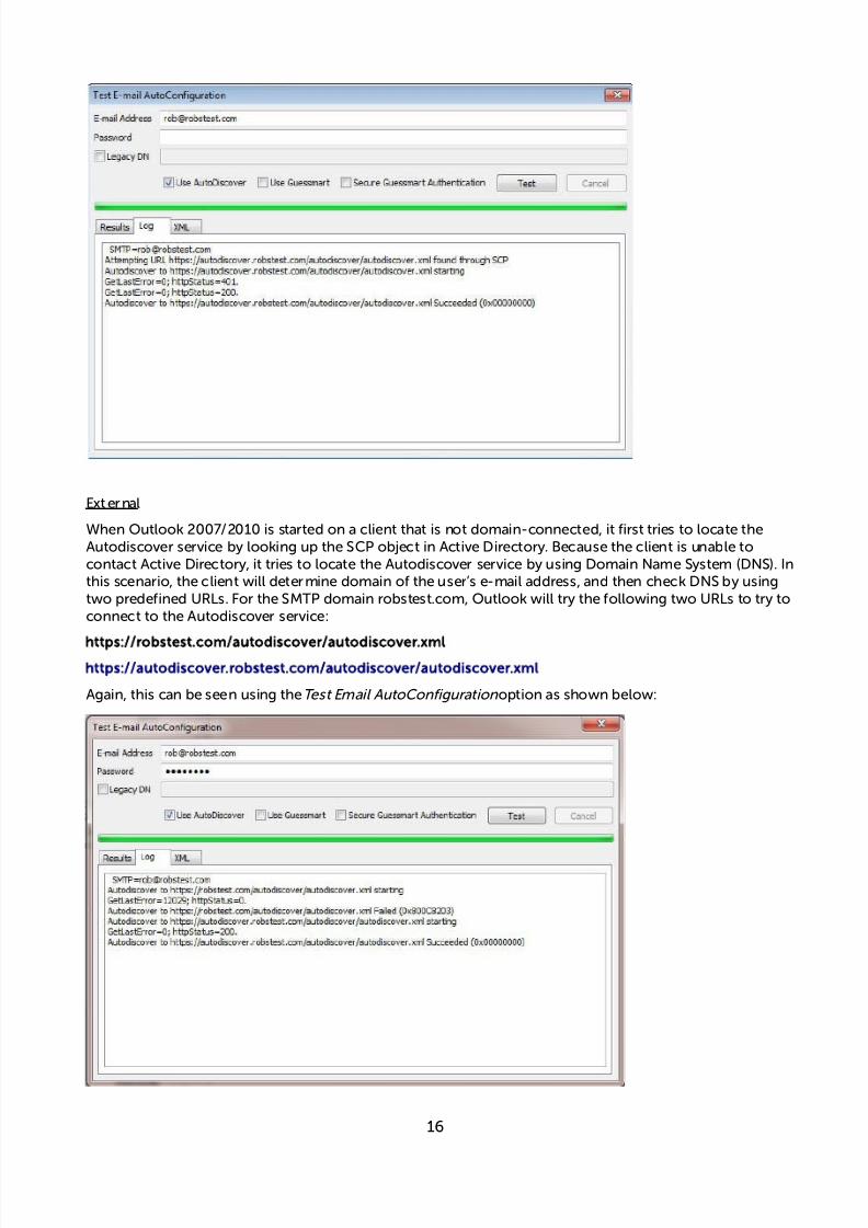
External
When Outlook 2007/2010 is started on a client that is not domain-connected, it first tries to locate theAutodiscover service by looking up the SCP object in Active Directory. Because the client is unable tocontact Active Directory, it tries to locate the Autodiscover service by using Domain Name System (DNS). Inthis scenario, the client will determine domain of the user’s e-mail address, and then check DNS by usingtwo predefined URLs. For the SMTP domain robstest.com, Outlook will try the following two URLs to try toconnect to the Autodiscover service:
https://robstest.com/autodiscover/autodiscover.xml
https://autodiscover.robstest.com/autodiscover/autodiscover.xml
Again, this can be seen using theTest Email AutoConfigurationoption as shown below:
16

7/18/2019 Microsoft Exchange 2013 Deployment Guide
http://slidepdf.com/reader/full/microsoft-exchange-2013-deployment-guide 17/49
Certificates
The recommended approach is to use SAN certificates and specify all required namespaces. It's alsopossible to use wildcard certs if preferred. Certificate requests can be generated using either the graphicalbased Exchange Admin Center or the command based Exchange Management Shell.
** IMPORTANT!! - the same certificate and private key must be deployed on all Exchange Servers **
NOTE: SSL offloading for Exchange 2013 is supported from SP1 as detailed in the followingMicrosoft article:http://technet.microsoft.com/library/dn635115(EXCHG.150).aspx. However,for scalability and effective load sharing we recommend terminating SSL on the ExchangeServers rather than on the load balancer.
Send & Receive Connectors
By default no send connectors are created when Exchange 2013 is installed. A send connector must be
created manually that either sends outbound email messages to a smart host or directly to their recipientusing DNS.
For a dual role server that has both the CAS and Mailbox roles, five receive connectors are automaticallycreated by default. The table below lists these connectors:
Receive Connector Role Purpose
Default <server name> Mailbox Accepts connections from Mailbox serversrunning the Transport service and from Edgeservers
Client Proxy <server name> Mailbox Accepts connections from front-end servers.Typically, messages are sent to a front-endserver over SMTP
Default FrontEnd <server name> CAS Accepts connections from SMTP senders overport 25. This is the common messaging entrypoint into your organization
Outbound Proxy Frontend <server name> CAS Accepts messages from a Send Connector on aback-end server, with front-end proxy enabled
Client Frontend <server name> CAS Accepts secure connections, with TransportLayer Security (TLS) applied
For more information on mail connectors please refer to the following Technet article:
http://technet.microsoft.com/en-us/library/jj657461(v=exchg.150).aspx
17
7/18/2019 Microsoft Exchange 2013 Deployment Guide
http://slidepdf.com/reader/full/microsoft-exchange-2013-deployment-guide 18/49
Adding Connectors
Connectors can be created using the Exchange Administration Center (EAC) or the Exchange ManagementShell. Receive connectors must use a unique combination of IP address bindings, port numberassignments, and remote IP address ranges from which mail is accepted. Multiple send connectors cancreated, this is typically done to enables multiple outbound email routes to specified that have differentcosts.
The exact connector configuration depends on your specific environment and requirements.
IIS Restart (Important step!)
Once all Exchange configuration is complete restart IIS on each server to ensure all changes are applied.This can be done using the following command in a command or Powershell Window:
iisreset /force
Exchange Server Configuration Steps (Depends on Load balancing Method)
DR Mode – Solve the ARP problem
The 'ARP problem' must be solved on each Exchange Server for DR mode to work. For detailed steps onsolving the ARP problem, please refer to the quick start guide available at the following link:
http://www.loadbalancer.org/pdf/quickstartguideLBVMv7.pdf
If you're using Windows 2008 then search this document for “Windows server 2008”
If you're using Windows 2012 then search this document for “Windows server 2012”
NAT Mode – Set the Exchange Servers Default Gateway
When using Layer 4 NAT mode, the default gateway on each Exchange Server MUST be set to be theloadbalancer. It's recommended that a floating IP address is used rather than the interface IP address. Thismakes it possible for the load balancer to failover to a slave unit and successfully bring up the gatewayaddress.
SNAT Mode
When using SNAT mode, no configuration changes to the Exchange Servers are required.
18

7/18/2019 Microsoft Exchange 2013 Deployment Guide
http://slidepdf.com/reader/full/microsoft-exchange-2013-deployment-guide 19/49
oadbalancer.org Appliance – the Basics
Network Configuration
The IP address, default gateway and DNS settings can be configured in several ways depending on theversion as detailed below.
Configure the IP address, Default Gateway & DNS Settings
Using the Network Setup Wizard at the console:
After boot, follow the console instructions to configure the IP address, gateway and DNS settings.
Using the WUI:
Using a browser, connect to the WUI on the default IP address/port:http://192.168.2.21:9080
to set the IP address use:Local Configuration > Network Interface Configurationto set the default gateway use:Local Configuration > Routingto configure DNS settings use: Local Configuration > Hostname & DNS
Using inux commands:
At the console, set the initial IP address using the following command:
ip addr add <IP address>/<mask> dev eth0e.g. ip addr add 192.168.2.10/24 dev eth0
At the console, set the initial default gateway using the following command:route add default gw <IP address> <interface>e.g. route add default gw 192.168.2.254 eth0
At the console, set the DNS server using the following command:echo nameserver <IP address> >> /etc/resolv.confe.g. echo nameserver 192.168.64.1 >> /etc/resolv.conf
N.B. If this method is used, you must also configure these settings using the WUI, otherwise settings willbe lost after a reboot
19

7/18/2019 Microsoft Exchange 2013 Deployment Guide
http://slidepdf.com/reader/full/microsoft-exchange-2013-deployment-guide 20/49
Accessing the Web User Interface (WUI)
The WUI can be accessed from a browser at:http://192.168.2.21:9080/lbadmin
* Note the port number 9080→
(replace 192.168.2.21 with the IP address of your load balancer if its been changed from the default)
Username: loadbalancer
Password: loadbalancer
Once you have entered the logon credentials the Loadbalancer.org Web User Interface will be displayed asshown below:
The screen shot below shows the v7.6 WUI once logged in:
20

7/18/2019 Microsoft Exchange 2013 Deployment Guide
http://slidepdf.com/reader/full/microsoft-exchange-2013-deployment-guide 21/49
Appliance Configuration for Exchange 2013 – Using DR Mode
NOTE: It's highly recommended that you have a working Exchange 2013 environment firstbefore implementing the load balancer.
Configure VIP1 – CAS Role HTTPS Services
a) Setting up the Virtual Service
• Using the WUI, go toCluster Configuration > Layer 4 – Virtual Service and click[Add a New Virtual Service]
• Enter the following details:
• Enter an appropriate label for the VIP, e.g.CAS-HTTPS
• Set theVirtual Service IP address field to the required IP address, e.g.192.168.30.10
• Set theVirtual Service Ports field to443
• LeaveProtocol set toTCP
• LeaveForwarding Method set toDirect Routing
• ClickUpdate
• Now click[Modify] next to the newly created VIP
• SetBalance modetoWeighted Round Robin
NOTE: Microsoft recommends that 'Round Robin' rather than 'Least Connection' should beused to help prevent over loading servers when they are brought online. This could occur ifLeast Connection was selected, since the load balancer would try to balance the number ofconnections across all real severs and therefore send all new requests to the new server. Thetrade off here is that using Round Robin will mean that server load may remain unbalancedfor some time after bringing a new server into the active pool.
• Un-check thePersistenceoption
• SetCheck TypetoNegotiate
• SetProtocol toHTTPS
21
7/18/2019 Microsoft Exchange 2013 Deployment Guide
http://slidepdf.com/reader/full/microsoft-exchange-2013-deployment-guide 22/49
• SetRequest to send toiisstart.htm
• SetResponse expected tomicrosoft
• ClickUpdate
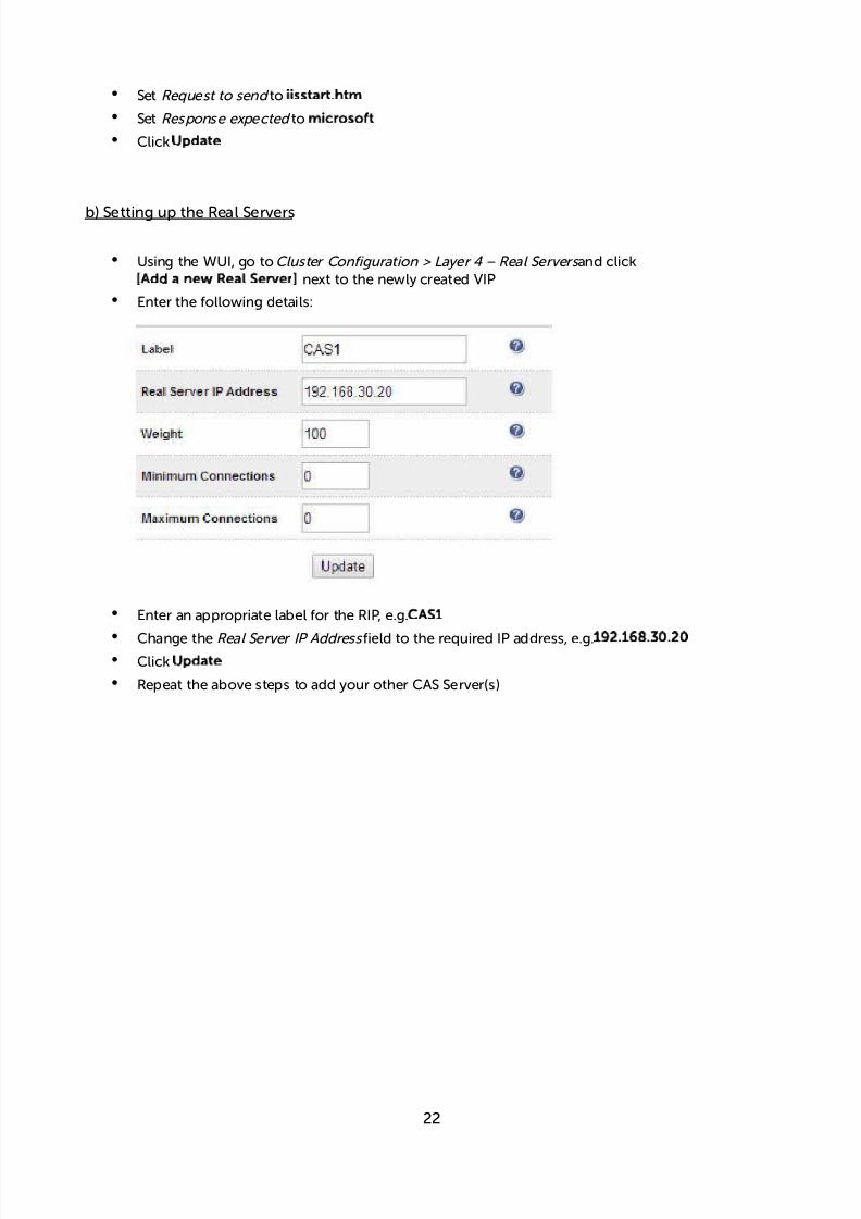
b) Setting up the Real Servers
• Using the WUI, go toCluster Configuration > Layer 4 – Real Servers and click[Add a new Real Server]next to the newly created VIP
• Enter the following details:
• Enter an appropriate label for the RIP, e.g.CAS1
• Change theReal Server IP Addressfield to the required IP address, e.g.192.168.30.20• ClickUpdate
• Repeat the above steps to add your other CAS Server(s)
22

7/18/2019 Microsoft Exchange 2013 Deployment Guide
http://slidepdf.com/reader/full/microsoft-exchange-2013-deployment-guide 23/49
Configure VIP2 – CAS Role IMAP4 / POP3 Services
a) Setting up the Virtual Service
N.B. these steps show IMAP4 settings, for POP3 change the port numbers from 143 & 993 to 110 & 995
• Using the WUI, go toCluster Configuration > Layer 4 – Virtual Service and click[Add a New Virtual Service]
• Enter the following details:
• Enter an appropriate label for the VIP, e.g.CAS-IMAP4
• Set theVirtual Service IP address field to the required IP address, e.g.192.168.30.10
• Set theVirtual Service Ports field to143,993
• LeaveProtocol set toTCP
• LeaveForwarding Method set toDirect Routing
• ClickUpdate
• Now click[Modify] next to the newly created VIP
• SetBalance modetoWeighted Round Robin
NOTE: Microsoft recommends that 'Round Robin' rather than 'Least Connection' should be usedto help prevent over loading servers when they are brought online. This could occur if LeastConnection was selected, since the load balancer would try to balance the number of
connections across all real severs and therefore send all new requests to the new server. Thetrade off here is that using Round Robin will mean that server load may remain unbalanced forsome time after bringing a new server into the active pool.
• Un-check thePersistenceoption
• ClickUpdate
23

7/18/2019 Microsoft Exchange 2013 Deployment Guide
http://slidepdf.com/reader/full/microsoft-exchange-2013-deployment-guide 24/49
b) Setting up the Real Servers
• Using the WUI, go toCluster Configuration > Layer 4 – Real Servers and click[Add a new Real Server]next to the newly created VIP
• Enter the following details:
• Enter an appropriate label for the RIP, e.g.CAS1
• Change theReal Server IP Addressfield to the required IP address, e.g.192.168.30.20
• ClickUpdate
• Repeat the above steps to add your other CAS Server(s)
24

7/18/2019 Microsoft Exchange 2013 Deployment Guide
http://slidepdf.com/reader/full/microsoft-exchange-2013-deployment-guide 25/49
Configure VIP3 – CAS Role SMTP Services
a) Setting up the Virtual Service
• Using the WUI, go toCluster Configuration > Layer 4 – Virtual Service and click
[Add a New Virtual Service] • Enter the following details:
• Enter an appropriate label for the VIP, e.g.CAS-SMTP
• Set theVirtual Service IP address field to the required IP address, e.g.192.168.30.10
• Set theVirtual Service Ports field to25
• LeaveProtocol set toTCP
• LeaveForwarding Method set toDirect Routing• ClickUpdate
• Now click[Modify] next to the newly created VIP
• Un-check thePersistenceoption
• ClickUpdate
25

7/18/2019 Microsoft Exchange 2013 Deployment Guide
http://slidepdf.com/reader/full/microsoft-exchange-2013-deployment-guide 26/49
b) Setting up the Real Servers
• Using the WUI, go toCluster Configuration > Layer 4 – Real Servers and click[Add a new Real Server]next to the newly created VIP
• Enter the following details:
• Enter an appropriate label for the RIP, e.g.CAS1
• Change theReal Server IP Addressfield to the required IP address, e.g.192.168.30.20
• ClickUpdate
• Repeat the above steps to add your other CAS Server(s)
Configure HTTP to HTTPS OWA Redirect
If required, the load balancer can be configured to automatically redirect users who attempt to connect tohttp://<URL to access OWA> to https://<URL to access OWA>. For details on configuring this, please referto section 4 in the Appendix.
26

7/18/2019 Microsoft Exchange 2013 Deployment Guide
http://slidepdf.com/reader/full/microsoft-exchange-2013-deployment-guide 27/49
Appliance Configuring for Exchange 2013 – Using NAT Mode
NOTE: It's highly recommended that you have a working Exchange 2013 environment firstbefore implementing the load balancer.
Configure VIP1 – CAS Role HTTPS Services
a) Setting up the Virtual Service
• Using the WUI, go toCluster Configuration > Layer 4 – Virtual Service and click[Add a New Virtual Service]
• Enter the following details:
• Enter an appropriate label for the VIP, e.g.CAS-HTTPS
• Set theVirtual Service IP address field to the required IP address, e.g.192.168.30.10
• Set theVirtual Service Ports field to443
• LeaveProtocol set toTCP
• Set theForwarding Method toNAT
• ClickUpdate
• Now click[Modify] next to the newly created VIP
• SetBalance modetoWeighted Round Robin
NOTE: Microsoft recommends that 'Round Robin' rather than 'Least Connection' should beused to help prevent over loading servers when they are brought online. This could occur ifLeast Connection was selected, since the load balancer would try to balance the number ofconnections across all real severs and therefore send all new requests to the new server. Thetrade off here is that using Round Robin will mean that server load may remain unbalancedfor some time after bringing a new server into the active pool.
• Un-check thePersistenceoption
• SetCheck TypetoNegotiate
• SetProtocol toHTTPS
27

7/18/2019 Microsoft Exchange 2013 Deployment Guide
http://slidepdf.com/reader/full/microsoft-exchange-2013-deployment-guide 28/49
• SetRequest to send toiisstart.htm
• SetResponse expected tomicrosoft
• ClickUpdate
b) Setting up the Real Servers
• Using the WUI, go toCluster Configuration > Layer 4 – Real Servers and click[Add a new Real Server]next to the newly created VIP
• Enter the following details:
• Enter an appropriate label for the RIP, e.g.CAS1
• Set theReal Server IP Addressfield to the required IP address, e.g.192.168.30.20
• set theReal Server Portfield to443
• ClickUpdate
• Repeat the above steps to add your other CAS Server(s)
28

7/18/2019 Microsoft Exchange 2013 Deployment Guide
http://slidepdf.com/reader/full/microsoft-exchange-2013-deployment-guide 29/49
Configure VIP2 – CAS Role IMAP4 / POP3 Services
a) Setting up the Virtual Service
N.B. these steps show IMAP4 settings, for POP3 change the port numbers from 143 & 993 to 110 & 995
• Using the WUI, go toCluster Configuration > Layer 4 – Virtual Service and click[Add a New Virtual Service]
• Enter the following details:
• Enter an appropriate label for the VIP, e.g.CAS-IMAP4
• Set theVirtual Service IP address field to the required IP address, e.g.192.168.30.10
• Set theVirtual Service Ports field to143,993
• LeaveProtocol set toTCP
• setForwarding Method toNAT
• ClickUpdate
• Now click[Modify] next to the newly created VIP
• SetBalance modetoWeighted Round Robin
NOTE: Microsoft recommends that 'Round Robin' rather than 'Least Connection' should be usedto help prevent over loading servers when they are brought online. This could occur if LeastConnection was selected, since the load balancer would try to balance the number of
connections across all real severs and therefore send all new requests to the new server. Thetrade off here is that using Round Robin will mean that server load may remain unbalanced forsome time after bringing a new server into the active pool.
• Un-check thePersistenceoption
• Click Update
29

7/18/2019 Microsoft Exchange 2013 Deployment Guide
http://slidepdf.com/reader/full/microsoft-exchange-2013-deployment-guide 30/49
b) Setting up the Real Servers
• Using the WUI, go toCluster Configuration > Layer 4 – Real Servers and click[Add a new Real Server]next to the newly created VIP
• Enter the following details:
• Enter an appropriate label for the RIP, e.g.CAS1
• Change theReal Server IP Addressfield to the required IP address, e.g.192.168.30.20
• Leave theReal Server Port field blank
• ClickUpdate
• Repeat the above steps to add your other CAS Server(s)
30
7/18/2019 Microsoft Exchange 2013 Deployment Guide
http://slidepdf.com/reader/full/microsoft-exchange-2013-deployment-guide 31/49
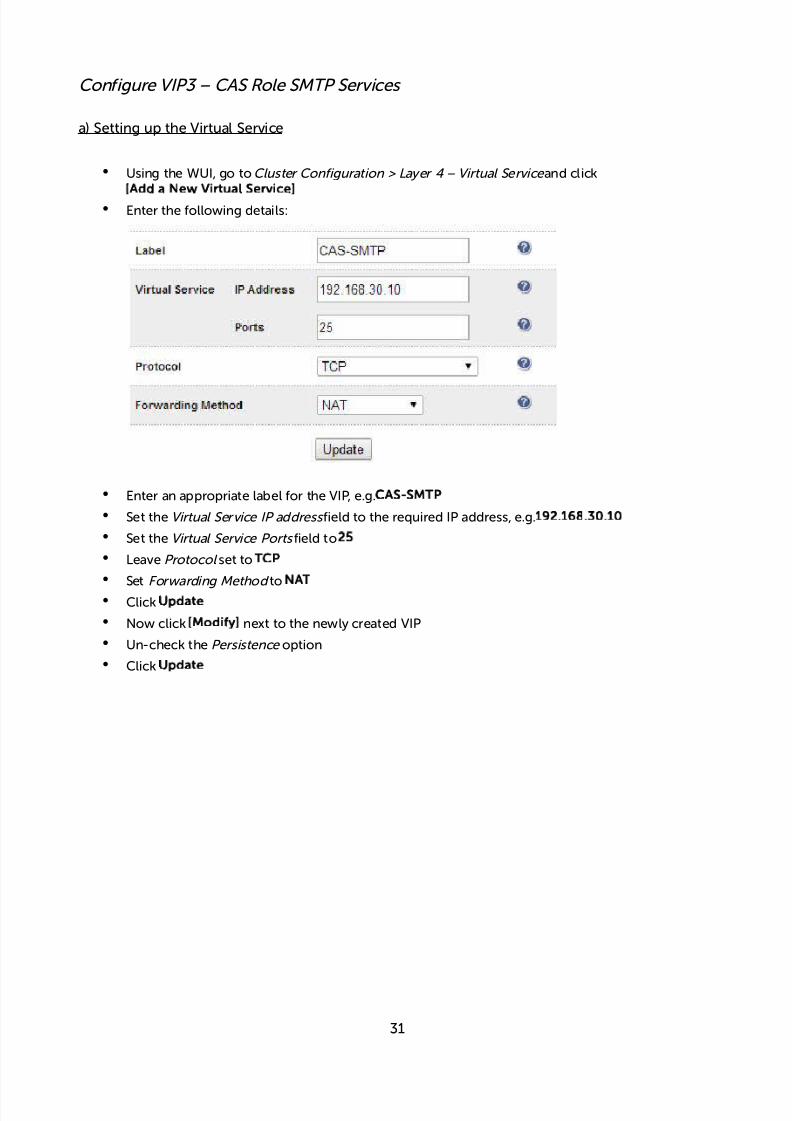
Configure VIP3 – CAS Role SMTP Services
a) Setting up the Virtual Service
• Using the WUI, go toCluster Configuration > Layer 4 – Virtual Service and click
[Add a New Virtual Service]
• Enter the following details:
• Enter an appropriate label for the VIP, e.g.CAS-SMTP
• Set theVirtual Service IP address field to the required IP address, e.g.192.168.30.10
• Set theVirtual Service Ports field to25
• LeaveProtocol set toTCP
• SetForwarding Method toNAT
• ClickUpdate
• Now click[Modify] next to the newly created VIP
• Un-check thePersistenceoption
• ClickUpdate
31

7/18/2019 Microsoft Exchange 2013 Deployment Guide
http://slidepdf.com/reader/full/microsoft-exchange-2013-deployment-guide 32/49
b) Setting up the Real Servers
• Using the WUI, go toCluster Configuration > Layer 4 – Real Servers and click[Add a new Real Server]next to the newly created VIP
• Enter the following details:
• Enter an appropriate label for the RIP, e.g.CAS1
• Change theReal Server IP Addressfield to the required IP address, e.g.192.168.30.20
• Change theReal Server Portfield to25
• ClickUpdate
• Repeat the above steps to add your other CAS Server(s)
Configure HTTP to HTTPS OWA Redirect
If required, the load balancer can be configured to automatically redirect users who attempt to connect tohttp://<URL to access OWA> to https://<URL to access OWA>. For details on configuring this, please referto section 4 in the Appendix.
32

7/18/2019 Microsoft Exchange 2013 Deployment Guide
http://slidepdf.com/reader/full/microsoft-exchange-2013-deployment-guide 33/49
Appliance Configuring for Exchange 2013 – Using SNAT mode
NOTE: It's highly recommended that you have a working Exchange 2013 environment firstbefore implementing the load balancer.
Configure Layer 7 Global Settings
To ensure that client connections remain open during periods of inactivity, the Client and Real ServerTimeout values must be changed from their default values of 43 seconds and 45 seconds respectively to 5minutes. To do this follow the steps below:
• Go toCluster Configuration > Layer 7 – Advanced Configuration
• ChangeClient Timeout to300000 as shown above (i.e. 5 minutes)
• ChangeReal Server Timeout to300000 as shown above (i.e. 5 minutes)
• Click theUpdate button to save the settings
33

7/18/2019 Microsoft Exchange 2013 Deployment Guide
http://slidepdf.com/reader/full/microsoft-exchange-2013-deployment-guide 34/49
Configure VIP1 – CAS Role HTTPS Services
a) Setting up the Virtual Service
• Using the WUI, go toCluster Configuration > Layer 7 – Virtual Service and click[Add a New Virtual Service]
• Enter the following details:
• Enter an appropriate label for the VIP, e.g.CAS-HTTPS
• Set theVirtual Service IP address field to the required IP address, e.g.192.168.30.10
• Set theVirtual Service Ports field to443
• SetLayer 7 Protocolset toTCP Mode
• ClickUpdate
• Now click[Modify] next to the newly created VIP
• SetBalance modetoWeighted Round Robin
NOTE: Microsoft recommends that 'Round Robin' rather than 'Least Connection' should beused to help prevent over loading servers when they are brought online. This could occur ifLeast Connection was selected, since the load balancer would try to balance the number ofconnections across all real severs and therefore send all new requests to the new server. Thetrade off here is that using Round Robin will mean that server load may remain unbalancedfor some time after bringing a new server into the active pool.
• EnsurePersistence Mode is set toNone
• ClickUpdate
34

7/18/2019 Microsoft Exchange 2013 Deployment Guide
http://slidepdf.com/reader/full/microsoft-exchange-2013-deployment-guide 35/49
b) Setting up the Real Servers
• Using the WUI, go toCluster Configuration > Layer 7 – Real Servers and click[Add a new Real Server]next to the newly created VIP
• Enter the following details:
• Enter an appropriate label for the RIP, e.g.CAS1
• Change theReal Server IP Addressfield to the required IP address, e.g.192.168.30.20
• Change theReal Server Portfield to443
• ClickUpdate
• Repeat the above steps to add your other CAS Server(s)
35

7/18/2019 Microsoft Exchange 2013 Deployment Guide
http://slidepdf.com/reader/full/microsoft-exchange-2013-deployment-guide 36/49
Configure VIP2 – CAS Role IMAP4 / POP3 Services
a) Setting up the Virtual Service
N.B. these steps show IMAP4 settings, for POP3 change the port numbers from 143 & 993 to 110 & 995
• Using the WUI, go toCluster Configuration > Layer 7 – Virtual Service and click[Add a New Virtual Service]
• Enter the following details:
• Enter an appropriate label for the VIP, e.g.CAS-IMAP4
• Set theVirtual Service IP address field to the required IP address, e.g.192.168.30.10
• Set theVirtual Service Ports field to143,993
• SetLayer 7 Protocol toTCP Mode
• ClickUpdate
• Now click[Modify] next to the newly created VIP
• SetBalance modetoWeighted Round Robin
NOTE: Microsoft recommends that 'Round Robin' rather than 'Least Connection' should beused to help prevent over loading servers when they are brought online. This could occur ifLeast Connection was selected, since the load balancer would try to balance the number ofconnections across all real severs and therefore send all new requests to the new server. Thetrade off here is that using Round Robin will mean that server load may remain unbalancedfor some time after bringing a new server into the active pool.
•EnsurePersistence Mode is set toNone
• ClickUpdate
36

7/18/2019 Microsoft Exchange 2013 Deployment Guide
http://slidepdf.com/reader/full/microsoft-exchange-2013-deployment-guide 37/49
b) Setting up the Real Servers
• Using the WUI, go toCluster Configuration > Layer 7 – Real Servers and click[Add a new Real Server]next to the newly created VIP
• Enter the following details:
• Enter an appropriate label for the RIP, e.g.CAS1
• Change theReal Server IP Addressfield to the required IP address, e.g.192.168.30.20
• Leave the Real Server Port field blank
• ClickUpdate
• Repeat the above steps to add your other CAS Server(s)
37

7/18/2019 Microsoft Exchange 2013 Deployment Guide
http://slidepdf.com/reader/full/microsoft-exchange-2013-deployment-guide 38/49
Configure VIP3 – CAS Role SMTP Services
NOTE: Source IP Address Transparency
It's important to remember that when using SNAT mode (HAProxy), the source IP address of packetsreaching the Exchange Servers will be the IP address of the load balancer and not the source IP address of
the client.If this is an issue, please refer to section 4 in the Appendix for details on using Tproxy. Tproxy enables theoriginal source IP address to be maintained, but requires that separate subnets are used, and also requiresthat the load balancer becomes the default gateway for the Exchange Servers. Enabling Tproxy is a globalsetting and therefore effects all Virtual Services configured on the load balancer which may not always bedesirable.
Transparency is normally only an issue for SMTP traffic at the receive connector. System Administratorstypically want to lock down receive connectors to accept SMTP connections only from a controlled set ofdevices such as external smart mail hosts, printers, networked photocopiers etc.
If transparency for SMTP is the only issue, there are a couple of options available to address this:
Option 1 – Enable full layer 7 transparency using Tproxy. This is covered in section 1 of the Appendix.
Option 2 – Enable the load balancers on-board firewall to lock down inbound SMTP connections ratherthan doing this at the receive connector. This is covered in section 2 of the Appendix.
Option 3 –Configure a layer 4 Virtual Service for SMTP rather than a layer 7 (HAProxy) based VirtualService. Layer 4 is transparent by default so the source IP address is maintained. This is covered in section 3of the Appendix.
a) Setting up the Virtual Service
• Using the WUI, go toCluster Configuration > Layer 7 – Virtual Service and click[Add a New Virtual Service]
• Enter the following details:
• Enter an appropriate label for the VIP, e.g.CAS-SMTP
• Set theVirtual Service IP address field to the required IP address, e.g.192.168.30.10
• Set theVirtual Service Ports field to25
• SetLayer 7 ProtocoltoTCP Mode
• ClickUpdate
38

7/18/2019 Microsoft Exchange 2013 Deployment Guide
http://slidepdf.com/reader/full/microsoft-exchange-2013-deployment-guide 39/49
• Now click[Modify] next to the newly created VIP
• EnsurePersistence Mode is set toNone
• ClickUpdate
b) Setting up the Real Servers
• Using the WUI, go toCluster Configuration > Layer 7 – Real Servers and click[Add a new Real Server]next to the newly created VIP
• Enter the following details:
• Enter an appropriate label for the RIP, e.g.CAS1
• Change theReal Server IP Addressfield to the required IP address, e.g.192.168.30.20
• Change the Real Server Port field to25
• ClickUpdate
• Repeat the above steps to add your other CAS Server(s)
Configure HTTP to HTTPS OWA Redirect
If required, the load balancer can be configured to automatically redirect users who attempt to connect tohttp://<URL to access OWA> to https://<URL to access OWA>. For details on configuring this, please referto section 4 in the Appendix.
Finalizing the Configuration
To apply the new settings, HAProxy must be restarted as follows:
• Go toMaintenance > Restart Servicesand clickRestart HAProxy
39
7/18/2019 Microsoft Exchange 2013 Deployment Guide
http://slidepdf.com/reader/full/microsoft-exchange-2013-deployment-guide 40/49
Testing & Verification
Useful Exchange 2013 & Other Microsoft Tools
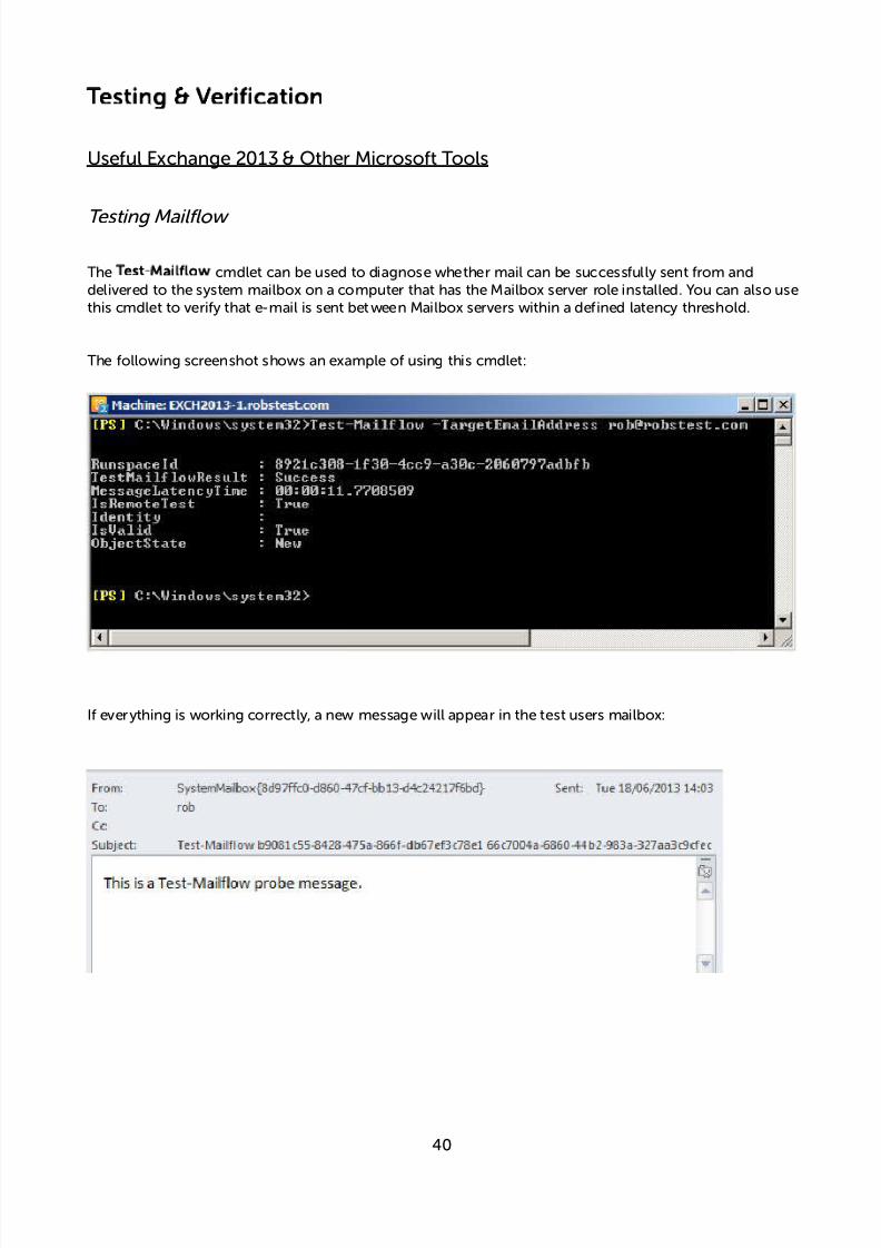
Testing Mailflow
TheTest-Mailflow cmdlet can be used to diagnose whether mail can be successfully sent from anddelivered to the system mailbox on a computer that has the Mailbox server role installed. You can also usethis cmdlet to verify that e-mail is sent between Mailbox servers within a defined latency threshold.
The following screenshot shows an example of using this cmdlet:
If everything is working correctly, a new message will appear in the test users mailbox:
40

7/18/2019 Microsoft Exchange 2013 Deployment Guide
http://slidepdf.com/reader/full/microsoft-exchange-2013-deployment-guide 41/49
Testing SMTP using Telnet
SMTP can be tested using telnet to connect to port 25, then by issuing various commands to simulate anemail being sent. Using S ystem Overview in the WUI, each CAS server can be tested by 'Halting' all othersthen running through the tests.
e.g. telnet 192.168.111.240 25
The following screenshot shows an example of using telnet to verify SMTP operation:
If everything is working correctly, a new message will appear in the test users mailbox:
To do the same test via the load balancer, connect to the VIP, e.g. : telnet mail.robstest.com 25
41

7/18/2019 Microsoft Exchange 2013 Deployment Guide
http://slidepdf.com/reader/full/microsoft-exchange-2013-deployment-guide 42/49
Microsoft Testing Tool
The Exchange Remote Connectivity Analyzer tool, available athttps://www.testexchangeconnectivity.com/ is a useful Web-based Microsoft tool designed to help ITAdministrators troubleshoot connectivity issues with their Exchange Server deployments. The toolsimulates several client logon and mail flow scenarios. When a test fails, many of the errors havetroubleshooting tips to assist the IT Administrator in correcting the problem.
Useful Appliance based Tools & Features
Using System Overview
The System Overview is accessed using the WUI. It shows a graphical view of all VIPs & RIPs (i.e. theExchange Servers) and shows the state/health of each server as well as the state of the each cluster as awhole. Th example below shows that both CAS servers are healthy and available to accept connections.
The example below shows that rip2 has been put in halt mode:
42

7/18/2019 Microsoft Exchange 2013 Deployment Guide
http://slidepdf.com/reader/full/microsoft-exchange-2013-deployment-guide 43/49
Layer 4 Status Report
The Layer 4 Status report gives a summary of layer 4 configuration and running stats as shown below. Thiscan be accessed in the WUI using the option:Reports > Layer 4 Status.
Layer 7 Statistics Report
The Layer 7 Statistics report gives a summary of all layer 7 configuration and running stats as shown below.This can be accessed in the WUI using the option:Reports > Layer 7 Status.
Appliance Logs
Logs are available for both layer 4 and layer 7 services and can be very useful when trying to diagnoseissues. Layer 4 logs are active by default and can be accessed using the WUI option:Logs > Layer 4.Layer 7logging is not enabled by default (because its extremely verbose) and can be enabled using the WUIoption:Cluster Configuration > Layer 7 – Advanced Configuration, and then viewed using the option:Logs> Layer 7.
43

7/18/2019 Microsoft Exchange 2013 Deployment Guide
http://slidepdf.com/reader/full/microsoft-exchange-2013-deployment-guide 44/49
Technical Support
For more details or assistance with your deployment please don't hesitate to contact the support team atthe following email address:[email protected]
Conclusion
Loadbalancer.org appliances provide a very cost effective solution for highly available load balancedExchange 2013 environments.
44

7/18/2019 Microsoft Exchange 2013 Deployment Guide
http://slidepdf.com/reader/full/microsoft-exchange-2013-deployment-guide 45/49
Appendix
1 – Enabling full Transparency using Tproxy (applies to Layer 7 SNAT mode)
As mentioned previously, Layer 7 SNAT mode is non-transparent by default. If a fully transparentconfiguration is required, Tproxy can be used. The main points to note are that two subnets must be usedand the default gateway on the Exchange Servers must be set to be the load balancer.
Key points to consider:
• The Exchange Servers must be on a different subnet to the VIP – this can achieved by using 2 IPaddresses assigned to a single interface, or two separate interfaces (eth0 & eth1)
• The default gateway on the Exchange Serversmust be configured to be an IP address on the loadbalancer. For a clustered pair of load balancers, It's best to add an additional floating IP for this toallow failover to the slave
• Tproxy must be enabled using the WUI:
Go toCluster Configuration>Layer 7 – Advanced Configuration and setTransparent Proxyto'On' and clickUpdate
N.B. If the load balancer has been deployed in Layer 4 DR or NAT mode, both are transparent by default sono additional steps are required. This section only applies when using Layer 7 SNAT mode.
45
Subnet 1 Subnet #
LoadBalancer
(single unitor clusteredpair)
InboundReuests
!I"(s)
CAS/MBOX #
$A%
CAS/MBOX 1

7/18/2019 Microsoft Exchange 2013 Deployment Guide
http://slidepdf.com/reader/full/microsoft-exchange-2013-deployment-guide 46/49
2 – Limiting inbound SMTP Connections using Firewall Rules (applies to Layer 7SNAT mode)
Since layer 7 is not transparent by default, it's not possible to filter inbound SMTP connections by IPaddress at the receive connector on the Hub Transport Server. One way to address this is to add firewallrules to the load balancer to limit which hosts can connect inbound on port 25.
Rules can be added using the WUI option:Maintenance > Firewall Script.Simply copy/paste/edit theexamples below into the firewall script then clickUpdate.
EXAMPLES:
1) to limit inbound SMTP connections to a specific smart host:
VIP1="192.168.30.10"
SRC1="192.168.30.50"
iptables -A INPUT -p tcp --src $SRC1 --dst $VIP1 --destination-port 25 -j ACCEPT
iptables -A INPUT -p tcp --dport 25 -j DROP
These rules will only allow SMTP traffic from the host 192.168.30.50 to reach the 192.168.30.10 VIP.
2) to limit inbound SMTP connections to a range of smart hosts:
VIP1="192.168.30.10"
SRC1="192.168.30.50-60"
iptables -A INPUT -p tcp -m iprange --src-range $SRC1 --destination $VIP1 --destination-port 25 -jACCEPT
iptables -A INPUT -p tcp --dport 25 -j DROP
These rules will only allow SMTP traffic from hosts in the range 192.168.30.50 through 192.168.30.60 to
reach the 192.168.30.10 VIP.
N.B. If the load balancer has been deployed in Layer 4 DR or NAT mode, both are transparent by default sono additional steps are required. This section only applies when using Layer 7 SNAT mode.
46

7/18/2019 Microsoft Exchange 2013 Deployment Guide
http://slidepdf.com/reader/full/microsoft-exchange-2013-deployment-guide 47/49
3 – Using a Layer 4 Virtual Service for SMTP
This guide uses Layer 7 HAProxy based Virtual Services for all load balanced services. Layer 7 VirtualServices are not transparent by default which can be an issue for SMTP. In these cases a Layer 4 VIP can beused instead for SMTP. There are two possibilities: DR (Direct Return) mode and NAT (Network AddressTranslation) mode. Layer 4 DR mode is covered on page 9 of this guide, Layer 4 NAT mode is covered onpage 10.
N.B. If the load balancer has been deployed in Layer 4 DR or NAT mode, both are transparent by default sono additional steps are required. This section only applies when using Layer 7 SNAT mode.
4 – Configuring an HTTP to HTTPS redirect for OWA
An additional layer 7 VIP is required that listens on HTTP port 80 on the same IP address. The VIP is thenconfigured to redirect connections to HTTPS port 443.
e.g.http://mail.robstest.com/owa should be redirected to https://mail.robstest.com/owa
The steps:
1) Create another ayer 7 VIP with the following settings:
• Label:HTTP-redirect
• Virtual Service IP Address:<same as the VIP that's listening on port 443>
• Virtual Service Ports:80
• Layer 7 Protocol:HTTP Mode
• Persistence Mode:None
• Force to HTTPS:Yes
N.B. This VIP will show in red in the System overview since no real servers are defined
2) Apply the new settings–to apply the new settings, HAProxy must be restarted:
• Using the WUI, go to:Maintenance > Restart Services and clickRestart HAProxy
47
7/18/2019 Microsoft Exchange 2013 Deployment Guide
http://slidepdf.com/reader/full/microsoft-exchange-2013-deployment-guide 48/49
5 – Clustered Pair Configuration – Adding a Slave Unit
If you initially configured just the master unit and now need to add a slave - our recommended procedure,please refer to the relevant document referenced below for more details:
Version 7
Please refer toChapter 8 – Appliance Clustering for HA in the v7 Administration Manual.
Version 8
Please refer toChapter 9 – Appliance Clustering for HA in the v8 Administration Manual.
Don't hesitate to contact our support team if you need further assistance:[email protected]
48

7/18/2019 Microsoft Exchange 2013 Deployment Guide
http://slidepdf.com/reader/full/microsoft-exchange-2013-deployment-guide 49/49
6 – Company Contact Information
Website
URL :www.loadbalancer.org
North America (US) Loadbalancer.org, Inc.270 Presidential DriveWilmington,DE 19807USA
Tel :Fax :
Email (sales) :Email (support) :
+1 888.867.9504 (24x7)+1 [email protected]@loadbalancer.org
North America (Canada) Loadbalancer.org Ltd.300-422 Richards StreetVancouver, BCV6B 2Z4Canada
Tel :Fax :
Email (sales) :Email (support) :
+1 855.681.6017 (24x7)+1 [email protected]@loadbalancer.org
Europe (UK) Loadbalancer.org Ltd.Portsmouth TechnopoleKingston CrescentPortsmouthPO2 8FAEngland, UK
Tel :Fax :
Email (sales) :Email (support) :
+44 (0)330 3801064 (24x7)+44 (0)870 [email protected]@loadbalancer.org
Europe (Germany) Loadbalancer.org GmbHAlt Pempelfort 240211 DüsseldorfGermany
Tel :Fax :
Email (sales) :Email (support) :
+49 (0)30 920 383 6494+49 (0)30 920 383 [email protected]@loadbalancer.org