hpe reference configuration for deploying microsoft ... hpe synergy composable infrastructure model...
TRANSCRIPT
HPE Reference Configuration for deploying Microsoft Exchange Server 2013 on HPE Synergy composable infrastructure
Technical white paper

Technical white paper
Contents Executive summary .................................................................................................................................................................................................................................................................................................................................3 Introduction ....................................................................................................................................................................................................................................................................................................................................................3 Solution overview ..................................................................................................................................................................................................................................................................................................................................... 4 Solution components ............................................................................................................................................................................................................................................................................................................................ 5
Hardware ................................................................................................................................................................................................................................................................................................................................................... 5 HPE Synergy Composer Modules and HPE Synergy Frame Link Modules ................................................................................................................................................................................ 7 HPE Synergy Compute Modules ......................................................................................................................................................................................................................................................................................... 8 HPE D3940 Storage Module .................................................................................................................................................................................................................................................................................................. 9
Exchange configuration guidance for the solution ................................................................................................................................................................................................................................................... 9 Exchange Server Preferred Architecture guidance............................................................................................................................................................................................................................................ 9 Exchange Server high availability and disaster resiliency ..........................................................................................................................................................................................................................10 Exchange database storage inside each Synergy Frame ........................................................................................................................................................................................................................... 12 Exchange network configuration options ................................................................................................................................................................................................................................................................. 13
Exchange Server capacity and sizing .................................................................................................................................................................................................................................................................................. 13 Analysis and recommendations ......................................................................................................................................................................................................................................................................................... 14 Data security ........................................................................................................................................................................................................................................................................................................................................ 14
Summary ........................................................................................................................................................................................................................................................................................................................................................ 14 Implementing a proof-of-concept ........................................................................................................................................................................................................................................................................................... 14 Appendix A: Bill of materials ........................................................................................................................................................................................................................................................................................................ 15 Resources and additional links .................................................................................................................................................................................................................................................................................................. 16

Technical white paper Page 3
Executive summary The deployment of data center infrastructure and business applications has become more complex with the addition of rapidly changing technology, higher uptime service level objectives, and the increasing complexity created by the addition of cloud and hybrid application deployment models compared to the traditional on premise model. The deployment of a single application like Microsoft® Exchange Server can involve multiple teams such as data center facilities, network, storage, server and the Exchange teams with each team providing a part of the overall configuration recipe, using their own specific expertise and toolsets to configure their components before handing it over to the next team in line. This is a time consuming process that requires an integrated approach to the overall project for deployment, management and monitoring and reconfiguration.
The introduction of the Hewlett Packard Enterprise Synergy composable infrastructure products simplifies this model by reducing the quantity of components and required skillsets needed for deployment. Deployment is accelerated by using HPE Synergy Composer as a single point for all interactions with HPE Synergy composable infrastructure. Pools of resources consisting of compute, storage and fabric can be deployed, managed and reconfigured using templates that describe the resources required for each server in an application. Once the initial template has been built, servers can be deployed quickly by specifying the template, server name and network address. This allows many steps in the configuration chain to be completed in a consistent and quick model allowing the entire infrastructure to be built out with as little administrative action as possible. For solutions like Exchange which use the same configuration for every server, the overall deployment process can be expedited and the possibility of administrative error reduced significantly.
The Exchange solution design presented in this reference configuration details the deployment of an Exchange 2013 environment that supports 42,000 – 6 GB mailboxes based on a profile of 150 messages sent and received per day for each user. The composable infrastructure components are assembled into building blocks based on an HPE Synergy 12000 Frame which is the foundation for a scalable infrastructure that contains pools of compute, storage, fabric, cooling and power resources with an embedded management solution and can be extended to fill a rack of four frames. The rack with the four frames is duplicated in the second site and the solution allows for a highly available and disaster resilient design which is easily deployed with the templates on the integrated set of Synergy components with all compute, storage and network hardware contained within the Synergy 12000 Frames.
The use of the composable infrastructure aligns with the Exchange Preferred Architecture deployment methodology to simplify the solution and provide a repeatable deployment experience with fewer components than other solutions.
Target audience: This HPE white paper is designed for IT professionals who design, build, and administer Microsoft Exchange deployments that require high availability and disaster resilience. Specifically, this information is intended for those who evaluate, recommend, or design Exchange messaging architectures.
The design concepts and sizing details included in this reference configuration are based on the Microsoft Exchange Preferred Architecture, best practices from Microsoft and HPE deployment guidance.
Introduction This reference configuration is one in a series that demonstrate the use of the HPE Synergy composable infrastructure to support enterprise applications. Composable infrastructure is designed around three core principles:
• A pool of resources including compute, storage and network that can be deployed, managed and reconfigured as business and application needs change.
• The ability to use templates or profiles to simply and quickly provision infrastructure resources in a repeatable and consistent manner.
• A unified API that provides access to all infrastructure components to provide access to hardware resources and allows for the management of hardware in a unified manner.
This series of projects demonstrates the concepts and solution designs used to place applications such as Microsoft Exchange, SQL, Oracle and other applications on the HPE composable infrastructure pools of compute, storage and fabric.
Microsoft Exchange is a business critical email workload that requires a balance of compute, storage and network. Microsoft Exchange provides high availability and disaster resiliency features within the application. Microsoft and Hewlett Packard Enterprise have a long relationship of collaborating to provide customers with stable Exchange communications infrastructure that meets their business requirements.
Technical white paper Page 4
The HPE Synergy composable infrastructure model offers design and scalability options for the deployment of Microsoft Exchange Server 2013. The Synergy Frame includes all of the components necessary for the deployment of Exchange. This includes compute modules, networking modules and storage modules that allow the messaging architect to specify an infrastructure composed of a balanced set of the elements necessary to make Exchange features available to customers while aligning to business needs and Service Level Objectives (SLO).
Design points included in this Exchange Server solution for deployment on composable infrastructure:
• Deployment of a highly available and disaster resilient Exchange Server architecture on the HPE Synergy composable infrastructure which allows implementation in a scalable manner with the ability to expand the architecture as needs change.
– Design the highly available Exchange solution to maintain client access in the event of the failure of a solution component.
– Define the service interruptions expected as connections are failed over from one component to another in the HA implementation.
• Align the deployment of Microsoft Exchange with Microsoft’s Exchange Preferred Architecture.
– Show examples of scale up and scale out scenarios for the Exchange server environment including multiple racks and Synergy Frames which include direct attached storage within each Synergy Frame using HPE D3940 Storage Modules.
– Demonstrate the advantage of pairing the HPE Virtual Connect SE 40Gb F8 Module with HPE Synergy 10Gb Interconnect Link Modules to extend Ethernet networking to multiple frames without top of rack switches to reduce overall solution cost and simplify management.
– Exhibit effective use of HPE Synergy Composer and HPE Synergy Frame Link Modules with consolidated management for compute modules, storage modules and networking components.
• Ensure that the solution design incorporates Microsoft and HPE design best practices while meeting customer requirements.
Solution overview The Synergy 12000 offers the following composable infrastructure for deploying Exchange:
• Two or four-socket compute modules
• Virtual Connect (HPE Virtual Connect SE 40Gb F8 Module) with Fibre Channel connectivity and network switch (HPE Synergy 40Gb F8 Switch Module)
• HPE Synergy D3940 12Gb SAS Storage Module supports up to 40 hot-pluggable 12 Gb small form factor drives with dual port connectivity including traditional hard drives and solid state drives.
The HPE Synergy 12000 Frame includes a consolidated management environment running on a redundant pair of HPE Synergy Composer Modules. Frame Link Modules connect up to 20 frames to manage, monitor and maintain compute, networking and storage components.
The use of the HPE Synergy composable infrastructure for applications allows the deployment and management of a set of hardware and subsequent adjustment of the balance of compute, storage, fabric and management in a simple and straightforward manner by either licensing the desired feature or the installation of additional compute modules or storage modules and drives. The wire-once model combined with the ability to expand compute, fabric and storage gives the user the ability to maintain the balance of hardware needs as application requirements change over time.
This Exchange Server 2013 solution design is built to show Exchange running at large scale and capitalize on the Synergy composable infrastructure features that allow for integration of hardware and management across multiple frames while reducing the overall cost of the solution. The design shows a configuration of two racks with each rack holding a set of four Synergy Frames. The second rack provides disaster resiliency and can be placed in a different part of the data center or a secondary data center. The design is expected to be run in an active/active configuration where active Outlook users connect to the servers contained in each rack. The next level of expansion of the solution can be made by adding another two racks for a total of four racks. Both the two and four rack configurations work in conjunction with the Exchange server high availability and the Database Availability Group (DAG) model to provide continued access to Exchange services for clients in the event of failure at the database, server, storage, network, rack or site level.
Technical white paper Page 5
Solution components The Synergy components used in this solution are based on a balanced architecture that uses components that fit within a set of four Synergy Frames within a rack and that design is duplicated for the second rack in the second site. The use of components that reside within the Synergy Frame allows for a simplification of design by using the fewest number of components necessary to deliver a highly available and disaster-resilient Exchange Server 2013 infrastructure.
Hardware This design for a highly available Microsoft Exchange Server 2013 solution uses a building block approach with each building block starting with a Synergy Frame and following Microsoft Best Practices as well as Microsoft’s Exchange Preferred Architecture principles as it is scaled up to multiple sites as Exchange-application-provided high availability and disaster resilient features are used. The solution is kept simple and uses similar components in each Synergy Frame so that the environment is straightforward to deploy, support and maintain.
The composable infrastructure used for this Microsoft Exchange Server solution uses the HPE Synergy 12000 Frame, HPE Synergy 480 Gen9 Compute Modules and the HPE D3940 Storage Modules as well as the supporting components discussed below. The solution that is appropriate to meet your company’s requirements is likely to differ from this design. HPE plans on updating the Sizer for Microsoft Exchange Server to include support for Exchange 2016 and for the HPE Synergy composable infrastructure components. A link to the sizer is included in the “Resources and additional links” section.
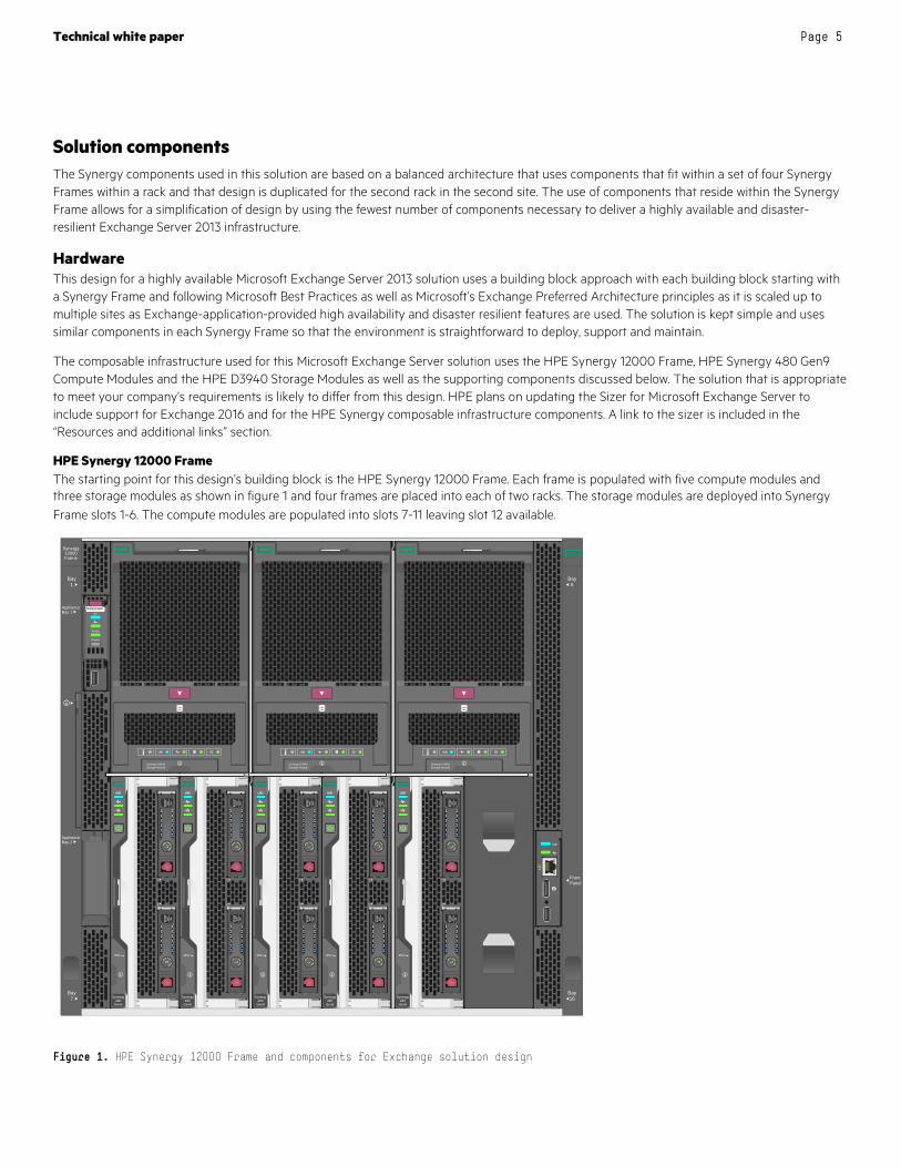
HPE Synergy 12000 Frame The starting point for this design’s building block is the HPE Synergy 12000 Frame. Each frame is populated with five compute modules and three storage modules as shown in figure 1 and four frames are placed into each of two racks. The storage modules are deployed into Synergy Frame slots 1-6. The compute modules are populated into slots 7-11 leaving slot 12 available.
Figure 1. HPE Synergy 12000 Frame and components for Exchange solution design
FrontPanel
Bay16
Bay6
Bay7
Bay1
ApplianceBay 2
ApplianceBay 1
Synergy12000Frame
UID
OneViewUID
Active
Power
Synergy Composer
UID
Synergy D3940Storage Module
UID
Synergy D3940Storage Module
UID
Synergy D3940Storage Module
1
2
UID
Synergy480
Gen9
1
2
UID
Synergy480
Gen9
1
2
UID
Synergy480
Gen9
1
2
UID
Synergy480
Gen9
1
2
UID
Synergy480
Gen9
SAS3 00 GB
15KSAS
3 00 GB
15K
SAS300 GB
15KSAS
300 GB
15K
SAS3 00 GB
1 5KSAS
3 00 GB
1 5K
SAS300 GB
15KSAS
300 GB
15K
SAS300 GB
15KSAS
3 00 GB
1 5K
Technical white paper Page 6
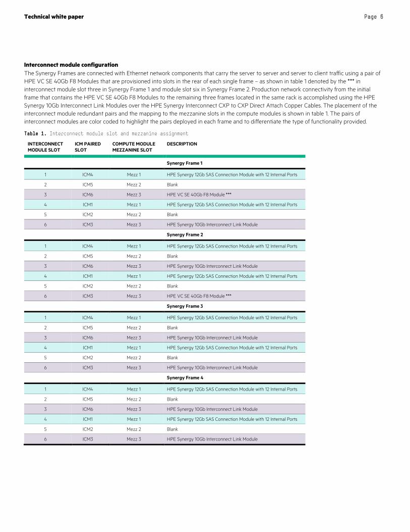
Interconnect module configuration The Synergy Frames are connected with Ethernet network components that carry the server to server and server to client traffic using a pair of HPE VC SE 40Gb F8 Modules that are provisioned into slots in the rear of each single frame – as shown in table 1 denoted by the *** in interconnect module slot three in Synergy Frame 1 and module slot six in Synergy Frame 2. Production network connectivity from the initial frame that contains the HPE VC SE 40Gb F8 Modules to the remaining three frames located in the same rack is accomplished using the HPE Synergy 10Gb Interconnect Link Modules over the HPE Synergy Interconnect CXP to CXP Direct Attach Copper Cables. The placement of the interconnect module redundant pairs and the mapping to the mezzanine slots in the compute modules is shown in table 1. The pairs of interconnect modules are color coded to highlight the pairs deployed in each frame and to differentiate the type of functionality provided.
Table 1. Interconnect module slot and mezzanine assignment
INTERCONNECT MODULE SLOT
ICM PAIRED SLOT
COMPUTE MODULE MEZZANINE SLOT
DESCRIPTION
Synergy Frame 1
1 ICM4 Mezz 1 HPE Synergy 12Gb SAS Connection Module with 12 Internal Ports
2 ICM5 Mezz 2 Blank
3 ICM6 Mezz 3 HPE VC SE 40Gb F8 Module ***
4 ICM1 Mezz 1 HPE Synergy 12Gb SAS Connection Module with 12 Internal Ports
5 ICM2 Mezz 2 Blank
6 ICM3 Mezz 3 HPE Synergy 10Gb Interconnect Link Module
Synergy Frame 2
1 ICM4 Mezz 1 HPE Synergy 12Gb SAS Connection Module with 12 Internal Ports
2 ICM5 Mezz 2 Blank
3 ICM6 Mezz 3 HPE Synergy 10Gb Interconnect Link Module
4 ICM1 Mezz 1 HPE Synergy 12Gb SAS Connection Module with 12 Internal Ports
5 ICM2 Mezz 2 Blank
6 ICM3 Mezz 3 HPE VC SE 40Gb F8 Module ***
Synergy Frame 3
1 ICM4 Mezz 1 HPE Synergy 12Gb SAS Connection Module with 12 Internal Ports
2 ICM5 Mezz 2 Blank
3 ICM6 Mezz 3 HPE Synergy 10Gb Interconnect Link Module
4 ICM1 Mezz 1 HPE Synergy 12Gb SAS Connection Module with 12 Internal Ports
5 ICM2 Mezz 2 Blank
6 ICM3 Mezz 3 HPE Synergy 10Gb Interconnect Link Module
Synergy Frame 4
1 ICM4 Mezz 1 HPE Synergy 12Gb SAS Connection Module with 12 Internal Ports
2 ICM5 Mezz 2 Blank
3 ICM6 Mezz 3 HPE Synergy 10Gb Interconnect Link Module
4 ICM1 Mezz 1 HPE Synergy 12Gb SAS Connection Module with 12 Internal Ports
5 ICM2 Mezz 2 Blank
6 ICM3 Mezz 3 HPE Synergy 10Gb Interconnect Link Module
Technical white paper Page 7
Benefit The combination of HPE VC SE 40Gb F8 Modules and Synergy Interconnect Link Modules obviate the need for a switch at the top of every rack and at the same time provides line rate performance to all frames, minimizes switch management, and simplifies the overall infrastructure management.
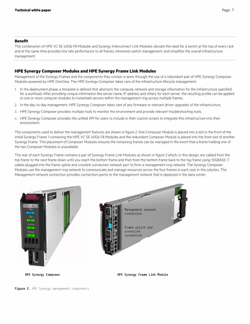
HPE Synergy Composer Modules and HPE Synergy Frame Link Modules Management of the Synergy Frames and the components they contain is done through the use of a redundant pair of HPE Synergy Composer Modules powered by HPE OneView. The HPE Synergy Composer takes care of the infrastructure lifecycle management.
1. In the deployment phase, a template is defined that abstracts the compute, network and storage information for the infrastructure specified for a workload. After providing unique information like server name, IP address and others for each server, the resulting profile can be applied to one or more compute modules to instantiate servers within the management ring across multiple frames.
2. In the day-to-day management, HPE Synergy Composer takes care of any firmware or relevant driver upgrades of the infrastructure.
3. HPE Synergy Composer provides multiple tools to monitor the environment and provide relevant troubleshooting tools.
4. HPE Synergy Composer provides the unified API for users to include in their custom scripts to integrate this infrastructure into their environment.
The components used to deliver the management features are shown in figure 2. One Composer Module is placed into a slot in the front of the initial Synergy Frame 1 containing the HPE VC SE 40Gb F8 Modules and the redundant Composer Module is placed into the front slot of another Synergy Frame. This placement of Composer Modules ensures the remaining frames can be managed in the event that a frame holding one of the two Composer Modules is unavailable.
The rear of each Synergy Frame contains a pair of Synergy Frame Link Modules as shown in figure 2 which, in this design, are cabled from the top frame to the next frame down until you reach the bottom frame and then from the bottom frame back to the top frame using 10GBASE-T cables plugged into the frame uplink and crosslink connection network port to form a management ring network. The Synergy Composer Modules use the management ring network to communicate and manage resources across the four frames in each rack in this solution. The Management network connection provides connection points to the management network that is deployed in the data center.
Figure 2. HPE Synergy management components
HPE Synergy Composer HPE Synergy Frame Link Module
Frame uplink and crosslink connection
Management networkconnection
Technical white paper Page 8
Benefit HPE Synergy Composer takes care of the infrastructure lifecycle management providing simpler, faster deployment, and ease of management in a scaled environment.
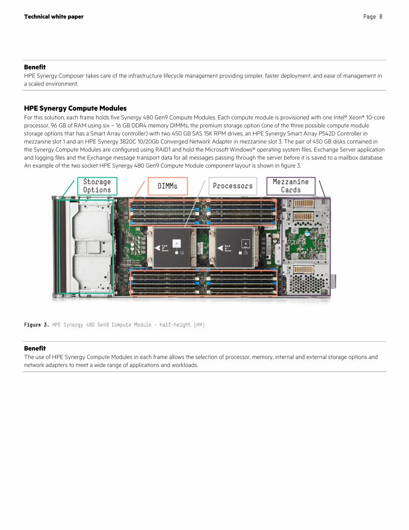
HPE Synergy Compute Modules For this solution, each frame holds five Synergy 480 Gen9 Compute Modules. Each compute module is provisioned with one Intel® Xeon® 10-core processor, 96 GB of RAM using six – 16 GB DDR4 memory DIMMs, the premium storage option (one of the three possible compute module storage options that has a Smart Array controller) with two 450 GB SAS 15K RPM drives, an HPE Synergy Smart Array P542D Controller in mezzanine slot 1 and an HPE Synergy 3820C 10/20Gb Converged Network Adapter in mezzanine slot 3. The pair of 450 GB disks contained in the Synergy Compute Modules are configured using RAID1 and hold the Microsoft Windows® operating system files, Exchange Server application and logging files and the Exchange message transport data for all messages passing through the server before it is saved to a mailbox database. An example of the two socket HPE Synergy 480 Gen9 Compute Module component layout is shown in figure 3.
Figure 3. HPE Synergy 480 Gen9 Compute Module – half-height (HH)
Benefit The use of HPE Synergy Compute Modules in each frame allows the selection of processor, memory, internal and external storage options and network adapters to meet a wide range of applications and workloads.
StorageOptions DIMMs Processors Mezzanine
Cards

Technical white paper Page 9
HPE D3940 Storage Module Every frame in this solution design contains three D3940 Storage Modules with an example shown in figure 4. Each D3940 Storage Module can hold up to 40 small form factor (SFF) drives that can be assigned to any compute module in the Synergy Frame. For this design, 23 - 2TB 12G SAS 7.2K rpm SFF drives are presented to each compute module. The disks contained in the D3940 Storage Module are configured with RAID0 on a single spindle and 21 of the disks each holds a set of two Exchange databases and their corresponding log files. Two additional disks are assigned to each server from a storage module with one disk used for database recovery operations and the other disk used for automatic reseeding of Exchange database data in the event of a physical disk failure. Each Exchange database disk is encrypted with Microsoft BitLocker to ensure data security in the event a disk is removed from the system. The D3940 Storage Module opens to provide access to the hot pluggable drives if a drive needs to be replaced.
Figure 4. HPE Synergy D3940 12Gb SAS Storage Module with 40 SFF Drive Bays
Benefit HPE Synergy D3940 Storage Modules in each frame provide higher density, scalability and flexibility to share the storage across the compute modules without the need for complex service operations and downtime to add or remove DAS.
Exchange configuration guidance for the solution The deployment of Exchange in this solution follows the Exchange Preferred Architecture as its guiding principle and incorporates Microsoft best practices and HPE deployment experience gained from previous Exchange deployments.
Exchange Server Preferred Architecture guidance The Microsoft Exchange Preferred Architecture (PA) available at http://blogs.technet.com/b/exchange/archive/2014/04/21/the-preferred-architecture.aspx provides guiding principles based on Exchange deployment best practices as well as input from the analysis of support cases that customers have opened with Microsoft as they experience Exchange outages or other problems where Exchange is not providing the expected behavior. The PA incorporates many helpful recommendations and a list of highlights are listed below:
• Simplicity: the more simple a design, the easier it is to deploy, maintain and troubleshoot.
• Site resiliency: adding a secondary site to your Exchange solution provides the ability to maintain higher feature availability to clients.
• Server design: guidance is provided on designing a consistent server configuration and expanding to meet your needs by adding servers that use the same layout.
• DAG design and witness server placement: this section discusses the use of multiple copies of each mailbox database and the location of the witness server to achieve the best availability for your needs.
Technical white paper Page 10
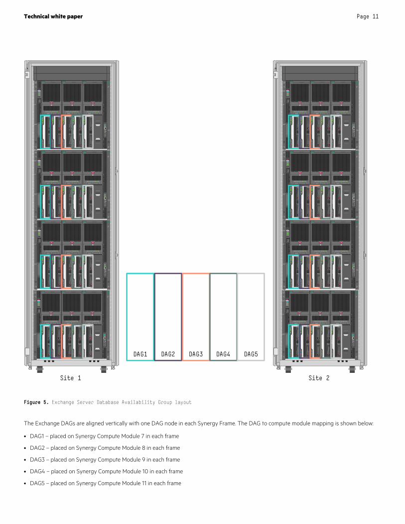
Exchange Server high availability and disaster resiliency Feedback from customers and partners has led to a focus on failure domains to ensure that Exchange features remain available to clients during periods of time when solution components are unavailable due to either maintenance activities (planned outages) or failure events (unplanned outages). Exchange uses Database Availability Groups (DAGs) to provide for continuous availability. In this solution, Exchange DAGs allow the placement of resources and database copies across racks, frames, network components, compute modules and storage modules to ensure that there are no single points of failure. A single DAG can contain up to 16 member servers and in this design we are using multiple DAGs which each contain eight member servers. The solution presented in this reference configuration is deployed across two racks with one in each site with the DAG node distribution shown in figure 5. Five DAGs are used in this solution design with four DAG nodes deployed in each of the two sites. Each Synergy Frame contains a DAG node from each Exchange DAG.
Exchange DAGs are based on the underlying Microsoft Windows failover cluster model and with an even number of nodes in the DAG a witness server is used so that the cluster has an odd number of quorum votes. The same witness server can be used for multiple DAGs and it is recommended that the server holding the witness server role reside in a third site so that cluster quorum is not lost in the event of a loss of either site or a WAN connection.
Technical white paper Page 11
Figure 5. Exchange Server Database Availability Group layout
The Exchange DAGs are aligned vertically with one DAG node in each Synergy Frame. The DAG to compute module mapping is shown below:
• DAG1 – placed on Synergy Compute Module 7 in each frame
• DAG2 – placed on Synergy Compute Module 8 in each frame
• DAG3 – placed on Synergy Compute Module 9 in each frame
• DAG4 – placed on Synergy Compute Module 10 in each frame
• DAG5 – placed on Synergy Compute Module 11 in each frame
01
02
03
04
05
06
07
08
09
10
11
12
13
14
15
16
17
18
19
20
21
22
23
24
25
26
27
28
29
30
31
32
33
34
35
36
37
38
39
40
41
42
01
02
03
04
05
06
07
08
09
10
11
12
13
14
15
16
17
18
19
20
21
22
23
24
25
26
27
28
29
30
31
32
33
34
35
36
37
38
39
40
41
42
FrontPanel
Bay16
Bay6
Bay7
Bay1
ApplianceBay 2
ApplianceBay 1
Synergy12000Frame
UID
OneViewUID
Active
Power
Synergy Composer
UID
Synergy D3940Storage Module
UID
Synergy D3940Storage Module
UID
Synergy D3940Storage Module
1
2
UID
Synergy480
Gen9
1
2
UID
Synergy480
Gen9
1
2
UID
Synergy480
Gen9
1
2
UID
Synergy480
Gen9
1
2
UID
Synergy480
Gen9
SAS300 GB
15KSAS
300 GB
15K
SAS300 GB
15KSAS
300 GB
15K
SAS300 GB
15 KSAS
300 GB
15 K
SAS300 GB
15KSAS
300 GB
15K
SAS300 GB
1 5KSAS
300 GB
15K
FrontPanel
Bay16
Bay6
Bay7
Bay1
ApplianceBay 2
ApplianceBay 1
Synergy12000Frame
UID
OneViewUID
Active
Power
Synergy Composer
UID
Synergy D3940Storage Module
UID
Synergy D3940Storage Module
UID
Synergy D3940Storage Module
1
2
UID
Synergy480
Gen9
1
2
UID
Synergy480
Gen9
1
2
UID
Synergy480
Gen9
1
2
UID
Synergy480
Gen9
1
2
UID
Synergy480
Gen9
SAS300 GB
15KSAS
300 GB
15 K
SAS300 GB
15KSAS
300 GB
15 K
SAS300 GB
15KSAS
300 GB
15K
SAS300 GB
15KSAS
300 GB
15K
SAS300 GB
15KSAS
300 GB
15K
FrontPanel
Bay16
Bay6
Bay7
Bay1
ApplianceBay 2
ApplianceBay 1
Synergy12000Frame
UID
OneViewUID
Active
Power
Synergy Composer
UID
Synergy D3940Storage Module
UID
Synergy D3940Storage Module
UID
Synergy D3940Storage Module
1
2
UID
Synergy480
Gen9
1
2
UID
Synergy480
Gen9
1
2
UID
Synergy480
Gen9
1
2
UID
Synergy480
Gen9
1
2
UID
Synergy480
Gen9
SAS300 GB
15 KSAS
300 GB
15K
SAS300 GB
15KSAS
300 GB
15K
SAS300 GB
15KSAS
300 GB
15K
SAS300 GB
15KSAS
300 GB
15K
SAS300 GB
15 KSAS
300 GB
15K
FrontPanel
Bay16
Bay6
Bay7
Bay1
ApplianceBay 2
ApplianceBay 1
Synergy12000Frame
UID
OneViewUID
Active
Power
Synergy Composer
UID
Synergy D3940Storage Module
UID
Synergy D3940Storage Module
UID
Synergy D3940Storage Module
1
2
UID
Synergy480
Gen9
1
2
UID
Synergy480
Gen9
1
2
UID
Synergy480
Gen9
1
2
UID
Synergy480
Gen9
1
2
UID
Synergy480
Gen9
SAS300 GB
15KSAS
300 GB
15K
SAS300 GB
15KSAS
300 GB
15K
SAS300 GB
15KSAS
300 GB
15K
SAS300 GB
15KSAS
300 GB
15K
SAS300 GB
15KSAS
300 GB
1 5K
DAG1 DAG2 DAG3 DAG4 DAG5 01
02
03
04
05
06
07
08
09
10
11
12
13
14
15
16
17
18
19
20
21
22
23
24
25
26
27
28
29
30
31
32
33
34
35
36
37
38
39
40
41
42
01
02
03
04
05
06
07
08
09
10
11
12
13
14
15
16
17
18
19
20
21
22
23
24
25
26
27
28
29
30
31
32
33
34
35
36
37
38
39
40
41
42
FrontPanel
Bay16
Bay6
Bay7
Bay1
ApplianceBay 2
ApplianceBay 1
Synergy12000Frame
UID
OneViewUID
Active
Power
Synergy Composer
UID
Synergy D3940Storage Module
UID
Synergy D3940Storage Module
UID
Synergy D3940Storage Module
1
2
UID
Synergy480
Gen9
1
2
UID
Synergy480
Gen9
1
2
UID
Synergy480
Gen9
1
2
UID
Synergy480
Gen9
1
2
UID
Synergy480
Gen9
SAS3 00 GB
1 5KSAS
3 00 GB
1 5K
SAS3 00 GB
15KSAS
3 00 GB
15K
SAS300 GB
15KSAS
3 00 GB
1 5K
SAS300 GB
1 5KSAS
300 GB
1 5K
SAS300 GB
1 5KSAS
300 GB
1 5K
FrontPanel
Bay16
Bay6
Bay7
Bay1
ApplianceBay 2
ApplianceBay 1
Synergy12000Frame
UID
OneViewUID
Active
Power
Synergy Composer
UID
Synergy D3940Storage Module
UID
Synergy D3940Storage Module
UID
Synergy D3940Storage Module
1
2
UID
Synergy480
Gen9
1
2
UID
Synergy480
Gen9
1
2
UID
Synergy480
Gen9
1
2
UID
Synergy480
Gen9
1
2
UID
Synergy480
Gen9
SAS300 GB
1 5KSAS
300 GB
1 5K
SAS3 00 GB
1 5KSAS
300 GB
15 K
SAS300 GB
15 KSAS
300 GB
15 K
SAS300 GB
15 KSAS
300 GB
15 K
SAS300 GB
15KSAS
300 GB
15K
FrontPanel
Bay16
Bay6
Bay7
Bay1
ApplianceBay 2
ApplianceBay 1
Synergy12000Frame
UID
OneViewUID
Active
Power
Synergy Composer
UID
Synergy D3940Storage Module
UID
Synergy D3940Storage Module
UID
Synergy D3940Storage Module
1
2
UID
Synergy480
Gen9
1
2
UID
Synergy480
Gen9
1
2
UID
Synergy480
Gen9
1
2
UID
Synergy480
Gen9
1
2
UID
Synergy480
Gen9
SAS300 GB
15 KSAS
300 GB
15 K
SAS300 GB
15 KSAS
300 GB
15 K
SAS3 00 GB
15 KSAS
300 GB
1 5K
SAS300 GB
1 5KSAS
3 00 GB
15 K
SAS300 GB
15KSAS
300 GB
15K
FrontPanel
Bay16
Bay6
Bay7
Bay1
ApplianceBay 2
ApplianceBay 1
Synergy12000Frame
UID
OneViewUID
Active
Power
Synergy Composer
UID
Synergy D3940Storage Module
UID
Synergy D3940Storage Module
UID
Synergy D3940Storage Module
1
2
UID
Synergy480
Gen9
1
2
UID
Synergy480
Gen9
1
2
UID
Synergy480
Gen9
1
2
UID
Synergy480
Gen9
1
2
UID
Synergy480
Gen9
SAS300 GB
1 5KSAS
300 GB
15 K
SAS300 GB
15KSAS
3 00 GB
15K
SAS300 GB
1 5KSAS
300 GB
15 K
SAS300 GB
15 KSAS
300 GB
15 K
SAS3 00 GB
1 5KSAS
3 00 GB
15K
Site 1 Site 2
Technical white paper Page 12
There is an open compute module slot in each frame. This could be used to install another server such as a load balancer. The deployment of two load balancers in each site would provide an easy method to add redundant load balancer functionality to better server Exchange client needs with a small amount of additional cost.
Benefit The Active/Active user distribution model across two sites ensures the lowest impact to the user base in the event that a planned or unplanned outage takes place.
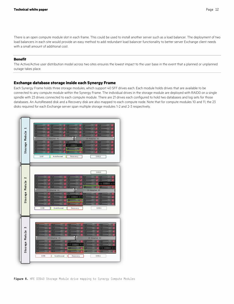
Exchange database storage inside each Synergy Frame Each Synergy Frame holds three storage modules, which support 40 SFF drives each. Each module holds drives that are available to be connected to any compute module within the Synergy Frame. The individual drives in the storage module are deployed with RAID0 on a single spindle with 23 drives connected to each compute module. There are 21 drives each configured to hold two databases and log sets for those databases. An AutoReseed disk and a Recovery disk are also mapped to each compute node. Note that for compute modules 10 and 11, the 23 disks required for each Exchange server span multiple storage modules 1-2 and 2-3 respectively.
Figure 6. HPE D3940 Storage Module drive mapping to Synergy Compute Modules
7 .2 KS A S2 T B
7 .2 KS A S2 T B
7 .2 KS A S2 T B
7 .2 KS A S2 T B
7 .2 KS A S2 T B
7 .2 KS A S2 T B
7 .2 KS A S2 T B
7 .2 KS A S2 T B
7 .2 KS A S2 T B
7 .2 KS A S2 T B
7 .2 KS A S2 T B
7 .2 KS A S2 T B
7 .2 KS A S2 T B
7 .2 KS A S2 T B
7 .2 KS A S2 T B
7 .2 KS A S2 T B
7 .2 KS A S2 T B
7 .2 KS A S2 T B
7 .2 KS A S2 T B
7 .2 KS A S2 T B
7 .2 KS A S2 T B
7 .2 KS A S2 T B
7 .2 KS A S2 T B
7 .2 KS A S2 T B
7 .2 KS A S2 T B
7 .2 KS A S2 T B
7 .2 KS A S2 T B
7 .2 KS A S2 T B
7 .2 KS A S2 T B
7 .2 KS A S2 T B
7 .2 KS A S2 T B
7 .2 KS A S2 T B
7 .2 KS A S2 T B
7 .2 KS A S2 T B
7 .2 KS A S2 T B
7 .2 KS A S2 T B
7 .2 KS A S2 T B
7 .2 KS A S2 T B
IO Adapter 01 IO Adapter 02
SVR9 AutoReseed Recovery SVR11
SVR10
7 .2 KS A S2 T B
7 .2 KS A S2 T B
7 .2 KS A S2 T B
7 .2 KS A S2 T B
7 .2 KS A S2 T B
7 .2 KS A S2 T B
7 .2 KS A S2 T B
7 .2 KS A S2 T B
7 .2 KS A S2 T B
7 .2 KS A S2 T B
7 .2 KS A S2 T B
7 .2 KS A S2 T B
7 .2 KS A S2 T B
7 .2 KS A S2 T B
7 .2 KS A S2 T B
7 .2 KS A S2 T B
7 .2 KS A S2 T B
7 .2 KS A S2 T B
7 .2 KS A S2 T B
7 .2 KS A S2 T B
7 .2 KS A S2 T B
7 .2 KS A S2 T B
7 .2 KS A S2 T B
7 .2 KS A S2 T B
7 .2 KS A S2 T B
7 .2 KS A S2 T B
7 .2 KS A S2 T B
7 .2 KS A S2 T B
7 .2 KS A S2 T B
7 .2 KS A S2 T B
7 .2 KS A S2 T B
7 .2 KS A S2 T B
7 .2 KS A S2 T B
7 .2 KS A S2 T B
7 .2 KS A S2 T B
7 .2 KS A S2 T B
7 .2 KS A S2 T B
7 .2 KS A S2 T B
7 .2 KS A S2 T B
IO Adapter 01 IO Adapter 02
SVR7 AutoReseed Recovery
SVR11
7 .2 KS A S2 T B
7 .2 KS A S2 T B
7 .2 KS A S2 T B
7 .2 KS A S2 T B
7 .2 KS A S2 T B
7 .2 KS A S2 T B
7 .2 KS A S2 T B
7 .2 KS A S2 T B
7 .2 KS A S2 T B
7 .2 KS A S2 T B
7 .2 KS A S2 T B
7 .2 KS A S2 T B
7 .2 KS A S2 T B
7 .2 KS A S2 T B
7 .2 KS A S2 T B
7 .2 KS A S2 T B
7 .2 KS A S2 T B
7 .2 KS A S2 T B
7 .2 KS A S2 T B
7 .2 KS A S2 T B
7 .2 KS A S2 T B
7 .2 KS A S2 T B
7 .2 KS A S2 T B
7 .2 KS A S2 T B
7 .2 KS A S2 T B
7 .2 KS A S2 T B
7 .2 KS A S2 T B
7 .2 KS A S2 T B
7 .2 KS A S2 T B
7 .2 KS A S2 T B
7 .2 KS A S2 T B
7 .2 KS A S2 T B
7 .2 KS A S2 T B
7 .2 KS A S2 T B
7 .2 KS A S2 T B
7 .2 KS A S2 T B
7 .2 KS A S2 T B
7 .2 KS A S2 T B
IO Adapter 01 IO Adapter 02
SVR8 AutoReseed Recovery
SVR10

Technical white paper Page 13
Note The Smart Array P542D storage controller offers a choice of acting as a traditional RAID controller or running in HBA mode, which then presents all attached drives directly to the operating system without RAID. Using the HBA configuration does not enable write caching and should not be used for Exchange databases due to the lower performance this causes. When using the default, as a traditional RAID controller, a new feature in the Smart Storage Administrator allows configuring individual drives as RAID0, which has the same net result of presenting the drives directly to the operating system while still using the Smart Array write caching.
A total of twelve (12) D3940 Storage Modules are deployed in each rack across the four Synergy Frames. The design uses 460 – 2 TB drives for Exchange database storage out of a total of 480 drive slots available in the D3940 Storage Modules in the rack.
Note The empty drive bays represented in figure 6 are not mapped to the server referenced since there is no drive to associate with a server. The figure is depicted in this manner for ease of representation of the concept of mapping drives in the Storage Module to the Compute Module.
Exchange network configuration options Each Synergy Frame provides redundant network connections which are provisioned to the Synergy 480 Gen9 Compute Modules through the use of the Synergy Composer. This provides each compute module with two 10 GbE connections through the HPE Synergy 3820C 10/20Gb Converged Network Adapter. The Microsoft Preferred Architecture recommends the deployment of a simple design with one network connection when using 10 GbE networks. The capability exists in Windows Server® 2012 R2 to team the two 10 GbE connections into a single logical network and the customer can decide if they prefer to use the redundant configuration that Windows teaming provides or to deploy a single (non-teamed) connection.
Exchange Server capacity and sizing Exchange server and storage sizing was performed using the Microsoft Exchange Server Role Requirements Calculator for Exchange 2013 (version 7.8) to calculate the server and storage design that provides a highly available and site resilient implementation that allows for the failures ranging from a single component up to an entire rack (site) while maintaining service to all 42,000 – 6 GB mailboxes with a workload of 150 messages sent and received per day per user. Version 7.8 of the Microsoft calculator has enabled sizing for Exchange Server 2016 in addition to Exchange Server 2013 so the sizing for both versions are included below.
Exchange Server 2013 is deployed in a multi-role configuration where the Client Access Server and Mailbox Server roles are combined as recommended by Microsoft. The load generated by combining both roles has been calculated into the compute and memory requirements for each Exchange Server. Microsoft has moved to a single role deployment methodology for Exchange Server 2016 that combines the Client Access Server (CAS) and Mailbox (MBX) server roles onto the same server. The difference in the amount of memory for the sizing of Exchange Server varies depending on the version of Exchange and the user distribution model shown in table 2.
Table 2. Sizing guidance for memory based on Exchange Server version and user distribution model
EXCHANGE SERVER VERSION MEMORY REQUIRED PER COMPUTE MODULE (ACTIVE/ACTIVE USER DISTRIBUTION MODEL)
MEMORY REQUIRED PER COMPUTE MODULE (ACTIVE/PASSIVE USER DISTRIBUTION MODEL)
Exchange Server 2013 (Multi-role: CAS + MBX) 96 GB 160 GB
Exchange Server 2016 96 GB 128 GB
A single Intel Xeon 10-core processor in each Synergy Compute Module is sufficient to support the workload during both normal operations and failure situations.
Two user distribution models were compared for the solution design:
• Active/Active: During normal operational situations half of the clients are connected to the Exchange servers in site 1 and half of the clients are connected to the Exchange servers in site 2. This model has the advantage that a site failure situation (the worst case) would result in the reconnection of 21,000 Exchange clients to the remaining site. This results in the lowest impact to the availability of Exchange Server overall.

Technical white paper Page 14
• Active/Passive: During normal operational situations all of the clients are connected to the Exchange servers in site 1. A site failure situation (the worst case) would result in the reconnection of all 42,000 Exchange clients to the disaster recovery site. This results in the highest impact to the availability of Exchange Server overall.
The design chosen was the Active/Active configuration where each site contains two copies of every mailbox database and the witness server is deployed in a third site to provide a design that can survive a site or WAN failure. The solution is able to run all client mailboxes from either of the two sites. Exchange Native Data Protection is used with four copies deployed across the two sites.
Note Microsoft guidance has recently changed to add a maximum recommended number of 24 processor cores with a maximum recommended memory of 96 GB. Additional information on this subject is detailed in the TechNet blog article: http://blogs.technet.com/b/exchange/archive/2015/06/19/ask-the-perf-guy-how-big-is-too-big.aspx. Testing of other Exchange designs by HPE has shown that increasing the RAM to 128 GB allows the number of users per server or workload of messages sent and received per day to be increased while still meeting acceptable performance without scaling so large to run into the support issues that Microsoft details in the above article.
The solution discussed in this reference configuration can be scaled out to support 84,000 clients with 6 GB mailboxes who each send and receive 150 messages per day and is based on 100% concurrent users by adding one rack of the same configuration into each site. The addition of the second rack in each site takes the solution to the maximum of 16 nodes per Exchange DAG while maintaining the ability to sustain availability of Exchange services to all 84,000 users.
Analysis and recommendations The Exchange Server 2013 solution presented in this reference configuration demonstrates the ability of the HPE Synergy components to enable close alignment with the key tenants of Microsoft’s Exchange Preferred Architecture.
• Simplicity: the more simple a design, the easier it is to deploy, maintain and troubleshoot.
• Site resiliency: adding a secondary site to your Exchange solution provides the ability to maintain higher feature availability to clients.
• Server design: guidance is provided on designing a consistent server configuration and expanding to meet your needs by adding servers that are configured with the same layout.
• DAG design and witness server placement: this section discusses the use of multiple copies of each mailbox database and the location of the witness server to achieve the best availability for your needs.
Data security The use of JBOD disks to hold client mailbox data in the Exchange databases presents a risk unless the data is encrypted. It is recommended to use Microsoft BitLocker in combination with a Trusted Platform Module (TPM) to permit the encryption of all storage, RAID 1 boot media and the JBOD disks used for Exchange database storage, connected to the compute node.
Summary The deployment of Microsoft Exchange 2013 on the Synergy composable infrastructure provides options that have not existed before now with the ability to use large quantities of direct attached storage within the Synergy 12000 Frame. The use of integrated networking interconnect modules allows the deployment of a simple networking model with a reduced number of components.
The composable infrastructure allows the deployment of a modular design that can be deployed quickly and modified easily using the Synergy Composer as needs change in the future due to new application requirements or a change in user demands or business needs.
Implementing a proof-of-concept As a matter of best practice for all deployments, HPE recommends implementing a proof-of-concept using a test environment that matches as closely as possible the planned production environment. In this way, appropriate performance and scalability characterizations can be obtained. For help with a proof-of-concept, contact an HPE Services representative (hpe.com/us/en/services/consulting.html) or your HPE partner.
Technical white paper Page 15
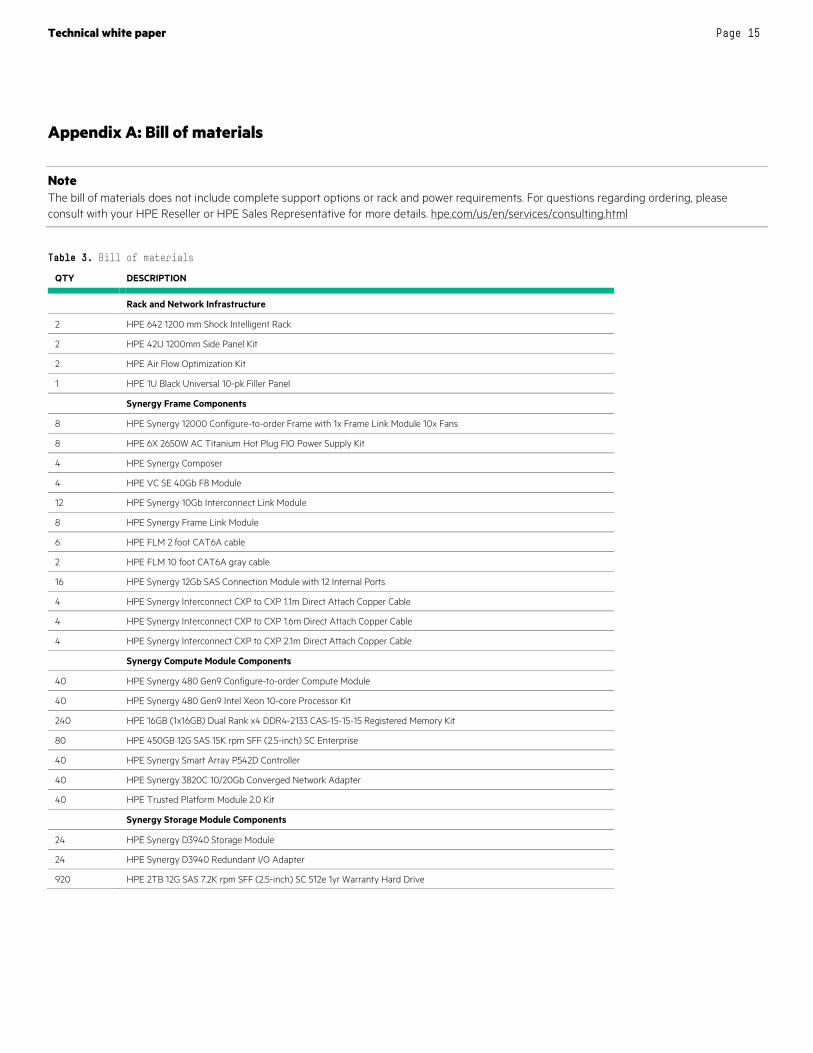
Appendix A: Bill of materials
Note The bill of materials does not include complete support options or rack and power requirements. For questions regarding ordering, please consult with your HPE Reseller or HPE Sales Representative for more details. hpe.com/us/en/services/consulting.html
Table 3. Bill of materials
QTY DESCRIPTION
Rack and Network Infrastructure
2 HPE 642 1200 mm Shock Intelligent Rack
2 HPE 42U 1200mm Side Panel Kit
2 HPE Air Flow Optimization Kit
1 HPE 1U Black Universal 10-pk Filler Panel
Synergy Frame Components
8 HPE Synergy 12000 Configure-to-order Frame with 1x Frame Link Module 10x Fans
8 HPE 6X 2650W AC Titanium Hot Plug FIO Power Supply Kit
4 HPE Synergy Composer
4 HPE VC SE 40Gb F8 Module
12 HPE Synergy 10Gb Interconnect Link Module
8 HPE Synergy Frame Link Module
6 HPE FLM 2 foot CAT6A cable
2 HPE FLM 10 foot CAT6A gray cable
16 HPE Synergy 12Gb SAS Connection Module with 12 Internal Ports
4 HPE Synergy Interconnect CXP to CXP 1.1m Direct Attach Copper Cable
4 HPE Synergy Interconnect CXP to CXP 1.6m Direct Attach Copper Cable
4 HPE Synergy Interconnect CXP to CXP 2.1m Direct Attach Copper Cable
Synergy Compute Module Components
40 HPE Synergy 480 Gen9 Configure-to-order Compute Module
40 HPE Synergy 480 Gen9 Intel Xeon 10-core Processor Kit
240 HPE 16GB (1x16GB) Dual Rank x4 DDR4-2133 CAS-15-15-15 Registered Memory Kit
80 HPE 450GB 12G SAS 15K rpm SFF (2.5-inch) SC Enterprise
40 HPE Synergy Smart Array P542D Controller
40 HPE Synergy 3820C 10/20Gb Converged Network Adapter
40 HPE Trusted Platform Module 2.0 Kit
Synergy Storage Module Components
24 HPE Synergy D3940 Storage Module
24 HPE Synergy D3940 Redundant I/O Adapter
920 HPE 2TB 12G SAS 7.2K rpm SFF (2.5-inch) SC 512e 1yr Warranty Hard Drive

Technical white paper Page 16
Sign up for updates
Rate this document
© Copyright 2015-2016 Hewlett Packard Enterprise Development LP. The information contained herein is subject to change without notice. The only warranties for HPE products and services are set forth in the express warranty statements accompanying such products and services. Nothing herein should be construed as constituting an additional warranty. HPE shall not be liable for technical or editorial errors or omissions contained herein.
Intel and Xeon are trademarks of Intel Corporation in the U.S. and other countries. Microsoft, Windows, and Windows Server are either registered trademarks or trademarks of Microsoft Corporation in the United States and/or other countries. Oracle is a registered trademark of Oracle and/or its affiliates.
4AA6-3238ENW, March 2016, Rev. 3
Resources and additional links HPE Sizer for Exchange 2013 http://h20195.www2.hpe.com/v2/GetDocument.aspx?docname=4AA6-0731ENW
HPE Enterprise Information Library - Microsoft Exchange http://h17007.www1.hpe.com/us/en/enterprise/converged-infrastructure/info-library/index.aspx?app=microsoft_exchange
HPE Synergy hpe.com/info/synergy
HPE Composable Infrastructure hpe.com/info/composableinfrastructure
HPE Enterprise Information Library hpe.com/info/convergedinfrastructure
HPE Technology Consulting Services hpe.com/us/en/services/consulting.html
To help us improve our documents, please provide feedback at hpe.com/contact/feedback.