micom p439 - technical manual -615 -618 -630 -631
TRANSCRIPT

MiCOM P439
Distance Protection and Control Unit
P439/EN M/Am5
Version P439 -304 -407/408 -615 P439 -304 -407/408 -618 P439 -305 -409/410 -630 P439 -305 -409/410 -631
Technical Manual Volume 2 of 2
Content P439/EN M/Cd4 (-615) P439/EN AD/Ae4 (-618) P439/EN AD/Ck5 (-630) P439/EN AD/Am5 (-631)


MiCOM P439
Distance Protection and Control Unit
P439/EN M/Cd4
Version P439 -304 -407/408 -615
Technical Manual Volume 2 of 2

Appendix
P439/EN M/Bd4 // AFSV.12.10190 D /// P439-304-407/408-615 AN-1
A Glossary
B Signal List
C List of Bay Types
D Overview of Changes
Terminal Connection Diagrams: See Volume 1, Chapter 5 “Installation and Connection”.
Appendix (continued)
P439/EN M/Bd4 // AFSV.12.10190 D /// P439-304-407/408-615 AN-2
A Glossary A-1A 1 Function Groups A-1A 2 Modules A-2A 3 Symbols A-3A 4 Examples of Signal Names A-10A 5 Symbols used A-11
B List of Signals B-1B 1 Internal Signal Names B-1B 2 Telecontrol Interface per EN 60870-5-101 or
IEC 870-5-101 (Companion Standard) B-6
B 2.1 Interoperability B-6B 2.1.1 Network Configuration (Network-Specific Parameters) B-6B 2.1.2 Physical Layer (Network-Specific Parameters) B-7B 2.1.3 Link Layer (Network-Specific Parameters) B-8B 2.1.4 Application Layer B-9B 2.1.5 Basic Application Functions B-15
B 3 Communication Interface per IEC 60870-5-103 B-18B 3.1 Interoperability B-18B 3.1.1 Physical Layer B-18B 3.1.1.1 Electrical Interface B-18B 3.1.1.2 Optical Interface B-18B 3.1.1.3 Transmission Rate B-18B 3.1.2 Link Layer B-19B 3.1.3 Application Layer B-19B 3.1.3.1 Transmission Mode for Application Data B-19B 3.1.3.2 Common Address of ASDU B-19B 3.1.3.3 Selection of Standard Information Numbers in Monitor
Direction B-19
B 3.1.3.3.1 System Functions in Monitor Direction B-19B 3.1.3.3.2 Status Indications in Monitor Direction B-20B 3.1.3.3.3 Monitoring Signals (Supervision Indications) in Monitor
Direction B-21
B 3.1.3.3.4 Earth Fault Indications in Monitor Direction B-22B 3.1.3.3.5 Fault Indications in Monitor Direction B-23B 3.1.3.3.6 Auto-Reclosure Indications in Monitor Direction B-25B 3.1.3.3.7 Measured values in Monitor Direction B-25B 3.1.3.3.8 Generic Functions in Monitor Direction B-26B 3.1.3.4 Selection of Standard Information Numbers in Control
Direction B-27
B 3.1.3.4.1 System Functions in Control Direction B-27B 3.1.3.4.2 General Commands in Control Direction B-27B 3.1.3.4.3 Generic Functions in Control Direction B-28B 3.1.3.5 Basic Application Functions B-29B 3.1.3.6 Miscellaneous B-29
C List of Bay Types C-1
D Overview of Changes D-1

Appendix A - Glossary
P439/EN M/Bd4 // AFSV.12.10190 D /// P439-304-407/408-615 A-1
A 1 Function Groups
IDMT: Inverse-Time Overcurrent Protection OUTP: Binary Outputs ARC: Auto-Reclosing Control CMD_1: Single-Pole Commands DEV01 to
DEV10: External Devices
OP_RC: Operating Data Recording DIST: Distance Protection GFTRP: Ground Fault Tripping INP: Binary Input GF_RC: Ground Fault Recording GF_DA: Ground Fault Data Acquisition GFSIG: Ground Fault Protection Signaling GFDSS: Ground Fault Direction Determination Using Steady-State
Values
TGFD: Transient Ground Fault Direction Determination f<>: Over-/Underfrequency Protection DVICE: Device LIMIT: Limit Value Monitoring MAIN: Main Function IRIGB: IRIG-B Interface COMM1: Communication Interface 1 COMM2: Communication Interface 2 LED: LED Indicators LOGIC: Logic CBM: Circuit Breaker Monitoring CBF: Circuit Breaker Failure Protection SIG_1: Single-Pole Signals MEASO: Measured Data Output MEASI: Measured Data Input MCMON: Measuring-Circuit Monitoring BUOC: Backup Overcurrent-Time Protection (Backup DTOC) P<>: Power Directional Protection PC: PC link PSB: Power Swing Blocking PSS: Parameter Subset Selection SFMON: Self-Monitoring ASC: Automatic Synchronism Check FT_RC: Fault Recording FT_DA: Fault Data Acquisition PSIG: Protective Signaling THERM: Thermal Overload Protection V<>: Time-Voltage Protection OL_RC: Overload Recording OL_DA: Overload Data Acquisition DTOC: Definite-Time Overcurrent Protection MT_RC: Monitoring Signal Recording ILOCK: Interlocking Logic LOC: Local Control Panel SOTF: Switch on to Fault Protection COUNT: Binary Counts

Appendix A - Glossary (continued)
A-2 P439/EN M/Bd4 // AFSV.12.10190 D /// P439-304-407/408-615
A 2 Modules
A: Communication module B: Digital bus module L: MMI module P: Processor module T: Transformer module V: Power supply module X: Binary I/O module Y: Analog I/O module
Appendix A - Glossary (continued)
P439/EN M/Bd4 // AFSV.12.10190 D /// P439-304-407/408-615 A-3
A 3 Symbols
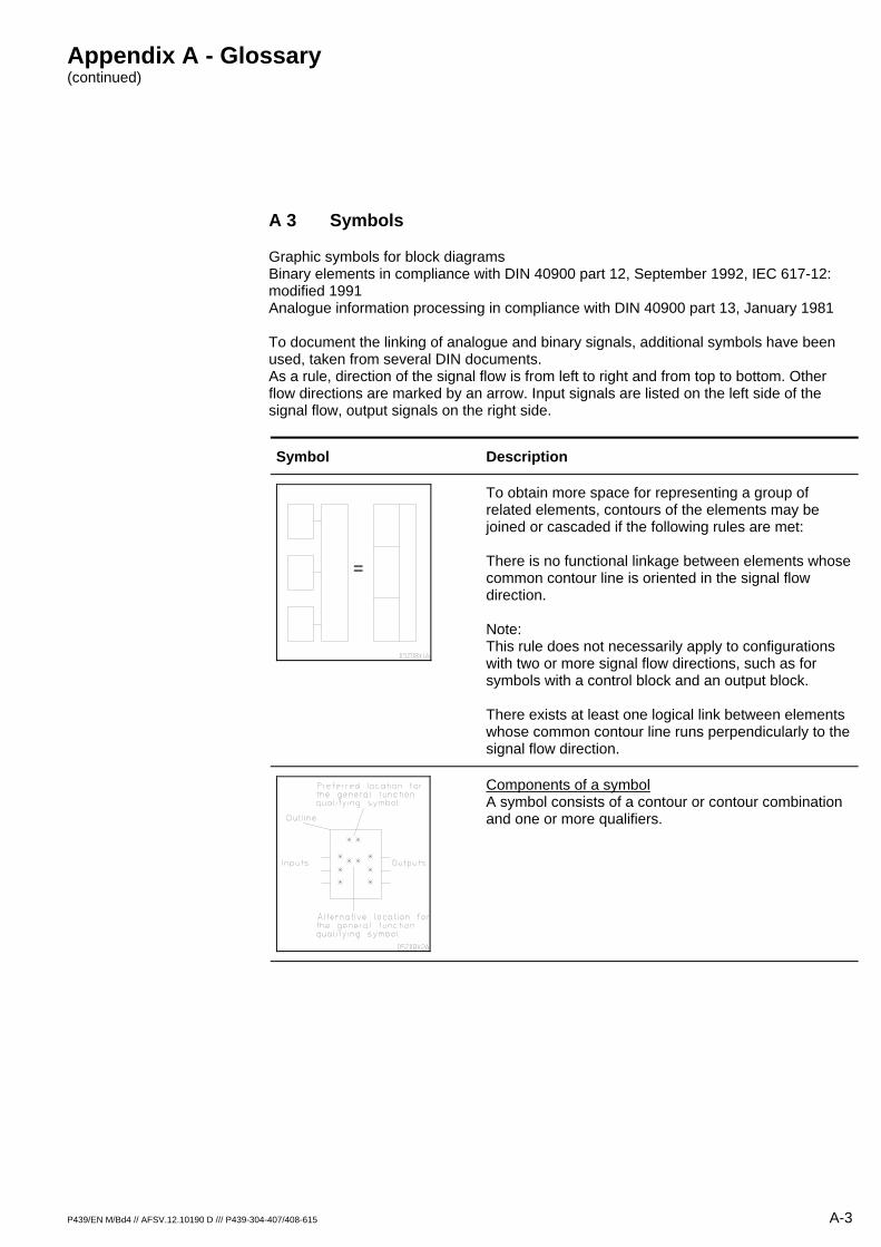
Graphic symbols for block diagrams Binary elements in compliance with DIN 40900 part 12, September 1992, IEC 617-12: modified 1991 Analogue information processing in compliance with DIN 40900 part 13, January 1981 To document the linking of analogue and binary signals, additional symbols have been used, taken from several DIN documents. As a rule, direction of the signal flow is from left to right and from top to bottom. Other flow directions are marked by an arrow. Input signals are listed on the left side of the signal flow, output signals on the right side.
Symbol Description
=
To obtain more space for representing a group of related elements, contours of the elements may be joined or cascaded if the following rules are met: There is no functional linkage between elements whose common contour line is oriented in the signal flow direction. Note: This rule does not necessarily apply to configurations with two or more signal flow directions, such as for symbols with a control block and an output block. There exists at least one logical link between elements whose common contour line runs perpendicularly to the signal flow direction.
Components of a symbol A symbol consists of a contour or contour combination and one or more qualifiers.
Appendix A - Glossary (continued)
A-4 P439/EN M/Bd4 // AFSV.12.10190 D /// P439-304-407/408-615
Symbol Description
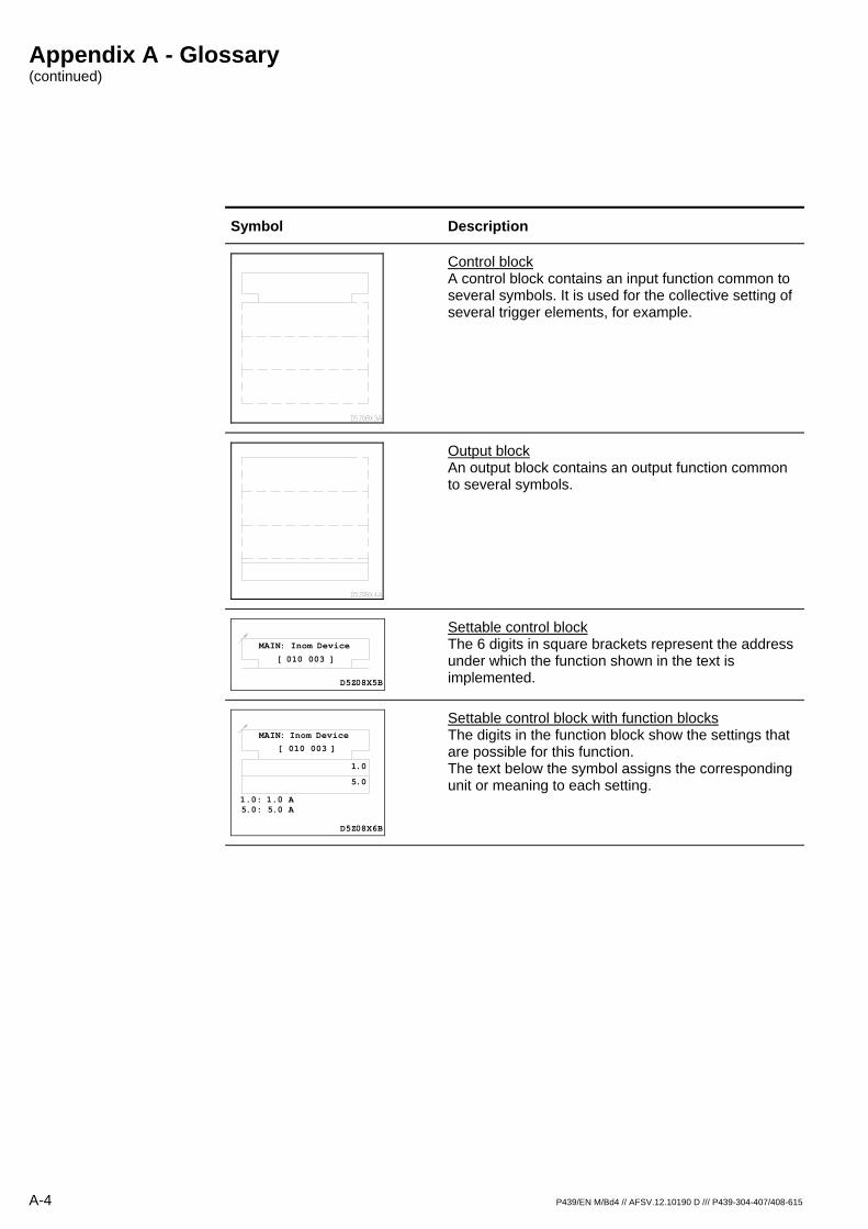
Control block A control block contains an input function common to several symbols. It is used for the collective setting of several trigger elements, for example.
Output block An output block contains an output function common to several symbols.
MAIN: Inom Device
[ 010 003 ]
D5Z08X5B
Settable control block The 6 digits in square brackets represent the address under which the function shown in the text is implemented.
MAIN: Inom Device
[ 010 003 ]
1.0
1.0: 1.0 A 5.0: 5.0 A
5.0
D5Z08X6B
Settable control block with function blocks The digits in the function block show the settings that are possible for this function. The text below the symbol assigns the corresponding unit or meaning to each setting.
Appendix A - Glossary (continued)
P439/EN M/Bd4 // AFSV.12.10190 D /// P439-304-407/408-615 A-5
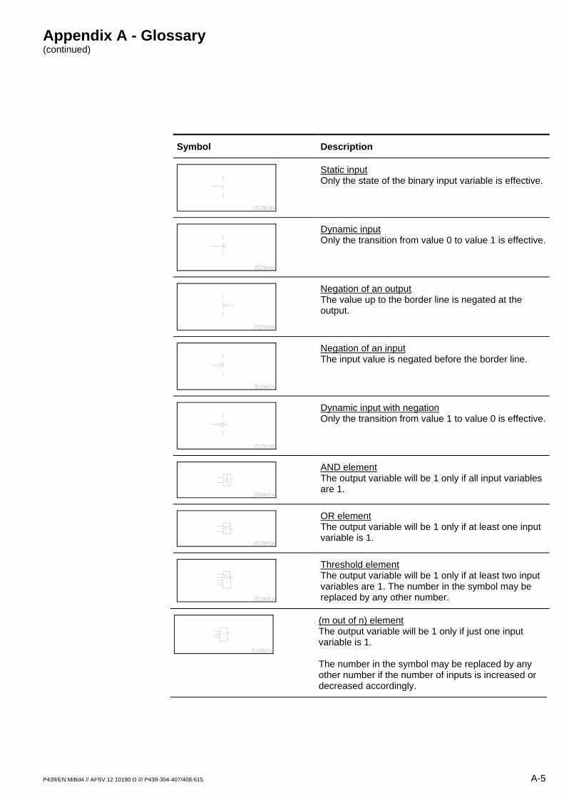
Symbol Description
Static input Only the state of the binary input variable is effective.
Dynamic input Only the transition from value 0 to value 1 is effective.
Negation of an output The value up to the border line is negated at the output.
Negation of an input The input value is negated before the border line.
Dynamic input with negation Only the transition from value 1 to value 0 is effective.
AND element The output variable will be 1 only if all input variables are 1.
OR element The output variable will be 1 only if at least one input variable is 1.
Threshold element The output variable will be 1 only if at least two input variables are 1. The number in the symbol may be replaced by any other number.
(m out of n) element The output variable will be 1 only if just one input variable is 1. The number in the symbol may be replaced by any other number if the number of inputs is increased or decreased accordingly.
Appendix A - Glossary (continued)
A-6 P439/EN M/Bd4 // AFSV.12.10190 D /// P439-304-407/408-615
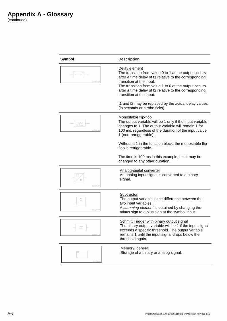
Symbol Description
Delay element The transition from value 0 to 1 at the output occurs after a time delay of t1 relative to the corresponding transition at the input. The transition from value 1 to 0 at the output occurs after a time delay of t2 relative to the corresponding transition at the input. t1 and t2 may be replaced by the actual delay values (in seconds or strobe ticks).
Monostable flip-flop The output variable will be 1 only if the input variable changes to 1. The output variable will remain 1 for 100 ms, regardless of the duration of the input value 1 (non-retriggerable). Without a 1 in the function block, the monostable flip-flop is retriggerable. The time is 100 ms in this example, but it may be changed to any other duration.
Analog-digital converter An analog input signal is converted to a binary signal.
Subtractor The output variable is the difference between the two input variables. A summing element is obtained by changing the minus sign to a plus sign at the symbol input.
Schmitt Trigger with binary output signal The binary output variable will be 1 if the input signal exceeds a specific threshold. The output variable remains 1 until the input signal drops below the threshold again.
Memory, general Storage of a binary or analog signal.

Appendix A - Glossary (continued)
P439/EN M/Bd4 // AFSV.12.10190 D /// P439-304-407/408-615 A-7
Symbol Description
Non-stable flip-flop When the input variable changes to 1, a pulse sequence is generated at the output. The ! to the left of the G indicates that the pulse sequence starts with the input variable transition (synchronized start). If there is a ! to the right of the G, the pulse sequence ends with the ending of the 1 signal at the input (synchronized stop).
Amplifier The output variable is 1 only if the input variable is also 1.
Band pass filter The output only transmits the 50 Hz component of the input signals. All other frequencies (above and below 50 Hz) are attenuated.
Counter At the + input the input variable transitions from 0 to 1 are counted and stored in the function block. At the R(eset) input a transition of the input variable from 0 to 1 resets the counter to 0.
Electromechanical drive in general, here a relay, for example.
Signal level converter with electrical isolation between input and output. L+ = pos. voltage input L- = neg. voltage input U1 = device identifier

Appendix A - Glossary (continued)
A-8 P439/EN M/Bd4 // AFSV.12.10190 D /// P439-304-407/408-615
Symbol Description
Input transformer with phase and item identifiers (according to DIN EN 60445) Phase identifiers for current inputs: for A: A1 and A2 for B: B1 and B2 for C: C1 and C2 for N: N1 and N2 Phase identifiers for voltage inputs via transformer 1: for A: 1U for B: 1V for C: 1W for N: 1N via transformer 2: for A: 2U for B: 2V Item identifiers for current transformers: for A: T1 for B: T2 for C: T3 for N: T4 for voltage transformer 1: for A: T5 for B: T6 for C: T7 for N: T8 for VG-N transformer: T90 for voltage transformer 2: for A: T15
Change-over contact with item identifier
Special symbol Output relay in normally-energized arrangement (‘closed-circuit operation’).

Appendix A - Glossary (continued)
P439/EN M/Bd4 // AFSV.12.10190 D /// P439-304-407/408-615 A-9
Symbol Description
PC interface with pin connections
Multiplier The output variable is the result of the multiplication of the two input variables.
Divider The output variable is the result of the division of the two input variables.
Comparator The output variable becomes 1 only if the input variable(s) are equal to the function in the function block.
Formula block The output variable becomes 1 only if the input variable(s) satisfy the equation in the function block
Appendix A - Glossary (continued)
A-10 P439/EN M/Bd4 // AFSV.12.10190 D /// P439-304-407/408-615
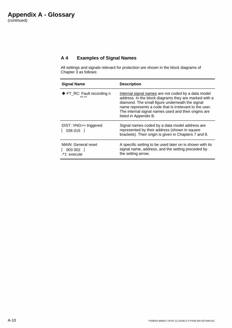
A 4 Examples of Signal Names
All settings and signals relevant for protection are shown in the block diagrams of Chapter 3 as follows:
Signal Name Description
FT_RC: Fault recording n 305 100
Internal signal names are not coded by a data model address. In the block diagrams they are marked with a diamond. The small figure underneath the signal name represents a code that is irrelevant to the user. The internal signal names used and their origins are listed in Appendix B.
DIST: VNG>> triggered [ 036 015 ]
Signal names coded by a data model address are represented by their address (shown in square brackets). Their origin is given in Chapters 7 and 8.
MAIN: General reset [ 003 002 ]
1: execute
A specific setting to be used later on is shown with its signal name, address, and the setting preceded by the setting arrow.
Appendix A - Glossary (continued)
P439/EN M/Bd4 // AFSV.12.10190 D /// P439-304-407/408-615 A-11
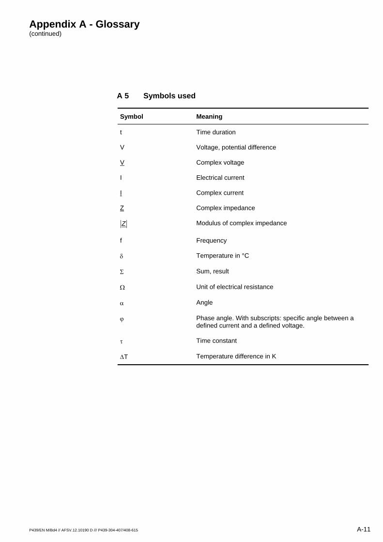
A 5 Symbols used
Symbol Meaning
t Time duration
V Voltage, potential difference
V Complex voltage
I Electrical current
I Complex current
Z Complex impedance
Z Modulus of complex impedance
f Frequency
δ Temperature in °C
Σ Sum, result
Ω Unit of electrical resistance
α Angle
ϕ Phase angle. With subscripts: specific angle between a defined current and a defined voltage.
τ Time constant
∆T Temperature difference in K

A-12 P439/EN M/Bd4 // AFSV.12.10190 D /// P439-304-407/408-615
Appendix B - List of signals
P439/EN M/Bd4 // AFSV.12.10190 D /// P439-304-407/408-615 B-1
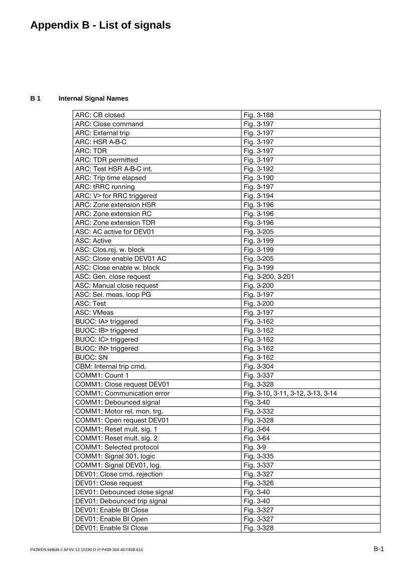
B 1 Internal Signal Names
ARC: CB closed Fig. 3-188 ARC: Close command Fig. 3-197 ARC: External trip Fig. 3-197 ARC: HSR A-B-C Fig. 3-197 ARC: TDR Fig. 3-197 ARC: TDR permitted Fig. 3-197 ARC: Test HSR A-B-C int. Fig. 3-192 ARC: Trip time elapsed Fig. 3-190 ARC: tRRC running Fig. 3-197 ARC: V> for RRC triggered Fig. 3-194 ARC: Zone extension HSR Fig. 3-196 ARC: Zone extension RC Fig. 3-196 ARC: Zone extension TDR Fig. 3-196 ASC: AC active for DEV01 Fig. 3-205 ASC: Active Fig. 3-199 ASC: Clos.rej. w. block Fig. 3-199 ASC: Close enable DEV01 AC Fig. 3-205 ASC: Close enable w. block Fig. 3-199 ASC: Gen. close request Fig. 3-200, 3-201 ASC: Manual close request Fig. 3-200 ASC: Sel. meas. loop PG Fig. 3-197 ASC: Test Fig. 3-200 ASC: VMeas Fig. 3-197 BUOC: IA> triggered Fig. 3-162 BUOC: IB> triggered Fig. 3-162 BUOC: IC> triggered Fig. 3-162 BUOC: IN> triggered Fig. 3-162 BUOC: SN Fig. 3-162 CBM: Internal trip cmd. Fig. 3-304 COMM1: Count 1 Fig. 3-337 COMM1: Close request DEV01 Fig. 3-328 COMM1: Communication error Fig. 3-10, 3-11, 3-12, 3-13, 3-14 COMM1: Debounced signal Fig. 3-40 COMM1: Motor rel. mon. trg. Fig. 3-332 COMM1: Open request DEV01 Fig. 3-328 COMM1: Reset mult. sig. 1 Fig. 3-64 COMM1: Reset mult. sig. 2 Fig. 3-64 COMM1: Selected protocol Fig. 3-9 COMM1: Signal 301, logic Fig. 3-335 COMM1: Signal DEV01, log. Fig. 3-337 DEV01: Close cmd. rejection Fig. 3-327 DEV01: Close request Fig. 3-326 DEV01: Debounced close signal Fig. 3-40 DEV01: Debounced trip signal Fig. 3-40 DEV01: Enable BI Close Fig. 3-327 DEV01: Enable BI Open Fig. 3-327 DEV01: Enable SI Close Fig. 3-328
Appendix B - List of signals (continued)
B-2 P439/EN M/Bd4 // AFSV.12.10190 D /// P439-304-407/408-615
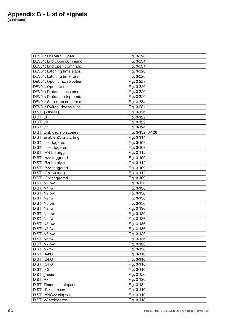
DEV01: Enable SI Open Fig. 3-328 DEV01: End close command Fig. 3-331 DEV01: End open command Fig. 3-331 DEV01: Latching time elaps. Fig. 3-326 DEV01: Latching time runn. Fig. 3-326 DEV01: Open cmd. rejection Fig. 3-327 DEV01: Open request Fig. 3-326 DEV01: Protect. close cmd. Fig. 3-329 DEV01: Protection trip cmd. Fig. 3-329 DEV01: Start runn.time mon. Fig. 3-334 DEV01: Switch. device runn. Fig. 3-331 DIST: |¾meas| Fig. 3-126 DIST: φF Fig. 3-122 DIST: φX Fig. 3-122 DIST: φZ Fig. 3-124 DIST: Dist. decision zone n Fig. 3-132, 3-128 DIST: Enable ZC-G starting Fig. 3-114 DIST: I>> triggered Fig. 3-109 DIST: I>>> triggered Fig. 3-109 DIST: IA>(Ibl) trigg. Fig. 3-112 DIST: IA>> triggered Fig. 3-109 DIST: IB>(Ibl) trigg. Fig. 3-112 DIST: IB>> triggered Fig. 3-109 DIST: IC>(Ibl) trigg. Fig. 3-112 DIST: IC>> triggered Fig. 3-109 DIST: N1,bw Fig. 3-136 DIST: N1,fw Fig. 3-136 DIST: N2,bw Fig. 3-136 DIST: N2,fw Fig. 3-136 DIST: N3,bw Fig. 3-136 DIST: N3,fw Fig. 3-136 DIST: N4,bw Fig. 3-136 DIST: N4,fw Fig. 3-136 DIST: N5,bw Fig. 3-136 DIST: N5,fw Fig. 3-136 DIST: N6,bw Fig. 3-136 DIST: N6,fw Fig. 3-136 DIST: N7,bw Fig. 3-136 DIST: N7,fw Fig. 3-136 DIST: ºA-kG Fig. 3-116 DIST: ºB-kG Fig. 3-116 DIST: ºC-kG Fig. 3-116 DIST: ºkG Fig. 3-116 DIST: ºmeas Fig. 3-120 DIST: RF Fig. 3-130 DIST: Timer st. 1 elapsed Fig. 3-134 DIST: tIN> elapsed Fig. 3-110 DIST: tVNG>> elapsed Fig. 3-110 DIST: VA< triggered Fig. 3-113
Appendix B - List of signals (continued)
P439/EN M/Bd4 // AFSV.12.10190 D /// P439-304-407/408-615 B-3
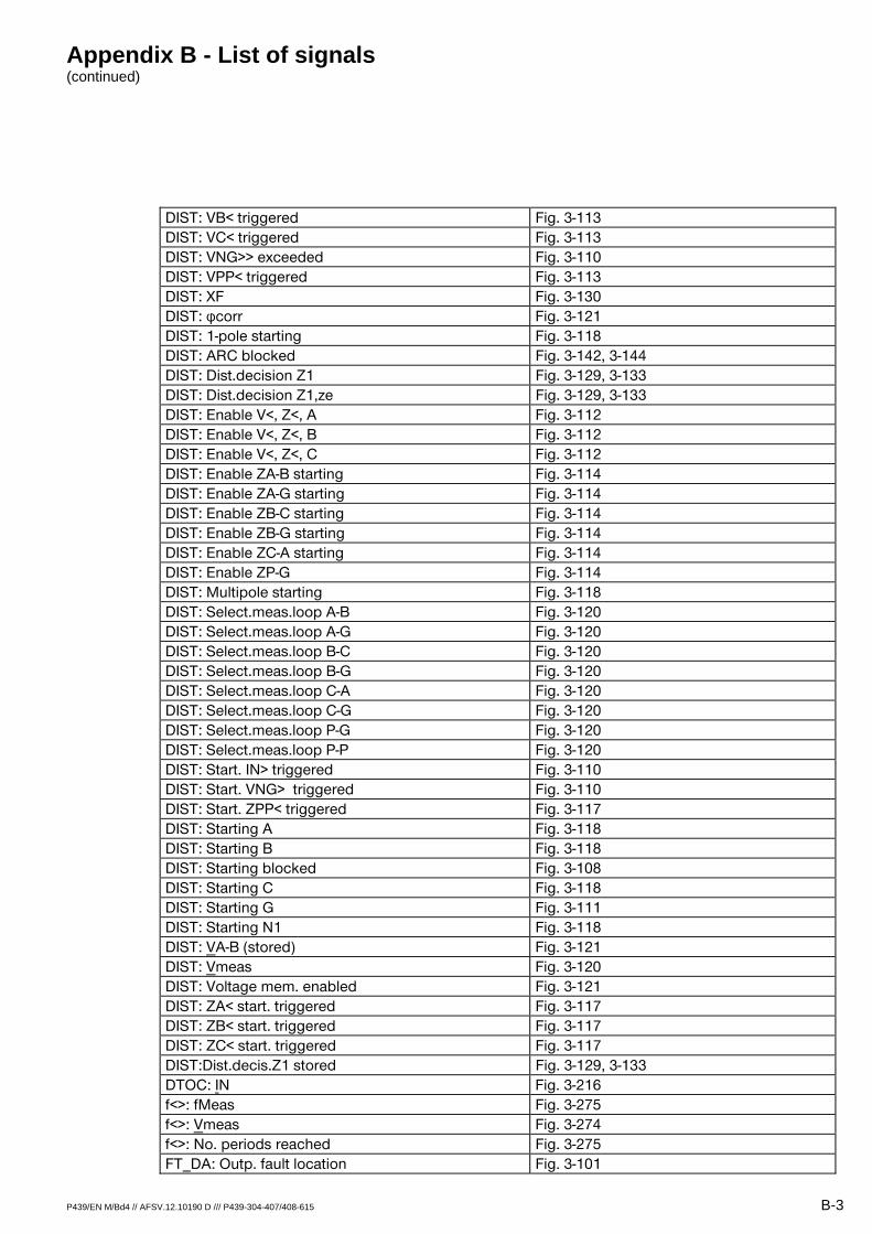
DIST: VB< triggered Fig. 3-113 DIST: VC< triggered Fig. 3-113 DIST: VNG>> exceeded Fig. 3-110 DIST: VPP< triggered Fig. 3-113 DIST: XF Fig. 3-130 DIST: φcorr Fig. 3-121 DIST: 1-pole starting Fig. 3-118 DIST: ARC blocked Fig. 3-142, 3-144 DIST: Dist.decision Z1 Fig. 3-129, 3-133 DIST: Dist.decision Z1,ze Fig. 3-129, 3-133 DIST: Enable V<, Z<, A Fig. 3-112 DIST: Enable V<, Z<, B Fig. 3-112 DIST: Enable V<, Z<, C Fig. 3-112 DIST: Enable ZA-B starting Fig. 3-114 DIST: Enable ZA-G starting Fig. 3-114 DIST: Enable ZB-C starting Fig. 3-114 DIST: Enable ZB-G starting Fig. 3-114 DIST: Enable ZC-A starting Fig. 3-114 DIST: Enable ZP-G Fig. 3-114 DIST: Multipole starting Fig. 3-118 DIST: Select.meas.loop A-B Fig. 3-120 DIST: Select.meas.loop A-G Fig. 3-120 DIST: Select.meas.loop B-C Fig. 3-120 DIST: Select.meas.loop B-G Fig. 3-120 DIST: Select.meas.loop C-A Fig. 3-120 DIST: Select.meas.loop C-G Fig. 3-120 DIST: Select.meas.loop P-G Fig. 3-120 DIST: Select.meas.loop P-P Fig. 3-120 DIST: Start. IN> triggered Fig. 3-110 DIST: Start. VNG> triggered Fig. 3-110 DIST: Start. ZPP< triggered Fig. 3-117 DIST: Starting A Fig. 3-118 DIST: Starting B Fig. 3-118 DIST: Starting blocked Fig. 3-108 DIST: Starting C Fig. 3-118 DIST: Starting G Fig. 3-111 DIST: Starting N1 Fig. 3-118 DIST: VA-B (stored) Fig. 3-121 DIST: Vmeas Fig. 3-120 DIST: Voltage mem. enabled Fig. 3-121 DIST: ZA< start. triggered Fig. 3-117 DIST: ZB< start. triggered Fig. 3-117 DIST: ZC< start. triggered Fig. 3-117 DIST:Dist.decis.Z1 stored Fig. 3-129, 3-133 DTOC: IN Fig. 3-216 f<>: fMeas Fig. 3-275 f<>: Vmeas Fig. 3-274 f<>: No. periods reached Fig. 3-275 FT_DA: Outp. fault location Fig. 3-101
Appendix B - List of signals (continued)
B-4 P439/EN M/Bd4 // AFSV.12.10190 D /// P439-304-407/408-615
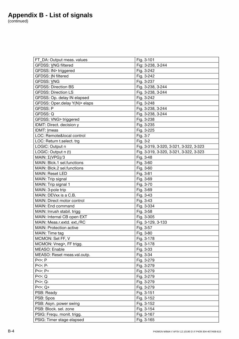
FT_DA: Output meas. values Fig. 3-101 GFDSS: ¼NG filtered Fig: 3-238, 3-244 GFDSS: IN> triggered Fig. 3-242 GFDSS: ºN filtered Fig. 3-242 GFDSS: VNG Fig. 3-237 GFDSS: Direction BS Fig. 3-238, 3-244 GFDSS: Direction LS Fig. 3-238, 3-244 GFDSS: Op. delay IN elapsed Fig. 3-242 GFDSS: Oper.delay Y(N)> elaps Fig. 3-248 GFDSS: P Fig. 3-238, 3-244 GFDSS: Q Fig. 3-238, 3-244 GFDSS: VNG> triggered Fig. 3-238 IDMT: Direct. decision y Fig. 3-235 IDMT: ºmeas Fig. 3-225 LOC: Remote&local control Fig. 3-7 LOC: Return t.select. trg Fig. 3-2 LOGIC: Output n Fig. 3-319, 3-320, 3-321, 3-322, 3-323 LOGIC: Output n (t) Fig. 3-319, 3-320, 3-321, 3-322, 3-323 MAIN: Σ(VPG)/3 Fig. 3-48 MAIN: Blck.1 sel.functions Fig. 3-60 MAIN: Blck.2 sel.functions Fig. 3-60 MAIN: Reset LED Fig. 3-81 MAIN: Trip signal Fig. 3-69 MAIN: Trip signal 1 Fig. 3-70 MAIN: 3-pole trip Fig. 3-69 MAIN: DEVxx is a C.B. Fig. 3-43 MAIN: Direct motor control Fig. 3-43 MAIN: End command Fig. 3-334 MAIN: Inrush stabil. trigg Fig. 3-58 MAIN: Internal CB open EXT Fig. 3-305 MAIN: Meas.r.extd. ext./RC Fig. 3-129, 3-133 MAIN: Protection active Fig. 3-57 MAIN: Time tag Fig. 3-80 MCMON: Set FF, V Fig. 3-178 MCMON: Vneg>, FF trigg. Fig. 3-178 MEASO: Enable Fig. 3-33 MEASO: Reset meas.val.outp. Fig. 3-34 P<>: P Fig. 3-279 P<>: P- Fig. 3-279 P<>: P+ Fig. 3-279 P<>: Q Fig. 3-279 P<>: Q- Fig. 3-279 P<>: Q+ Fig. 3-279 PSB: Ready Fig. 3-151 PSB: Spos Fig. 3-152 PSB: Asyn. power swing Fig. 3-152 PSB: Block. sel. zone Fig. 3-154 PSIG: Frequ. monit. trigg. Fig. 3-167 PSIG: Timer stage elapsed Fig. 3-165
Appendix B - List of signals (continued)
P439/EN M/Bd4 // AFSV.12.10190 D /// P439-304-407/408-615 B-5
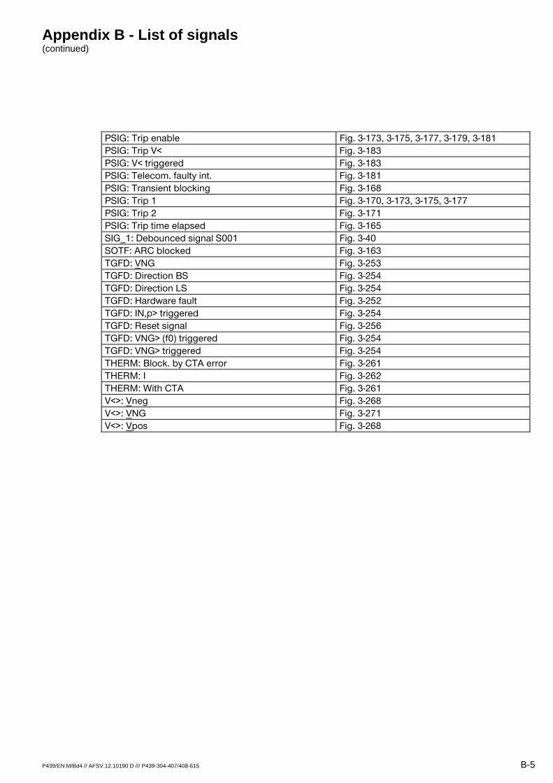
PSIG: Trip enable Fig. 3-173, 3-175, 3-177, 3-179, 3-181 PSIG: Trip V< Fig. 3-183 PSIG: V< triggered Fig. 3-183 PSIG: Telecom. faulty int. Fig. 3-181 PSIG: Transient blocking Fig. 3-168 PSIG: Trip 1 Fig. 3-170, 3-173, 3-175, 3-177 PSIG: Trip 2 Fig. 3-171 PSIG: Trip time elapsed Fig. 3-165 SIG_1: Debounced signal S001 Fig. 3-40 SOTF: ARC blocked Fig. 3-163 TGFD: VNG Fig. 3-253 TGFD: Direction BS Fig. 3-254 TGFD: Direction LS Fig. 3-254 TGFD: Hardware fault Fig. 3-252 TGFD: IN,p> triggered Fig. 3-254 TGFD: Reset signal Fig. 3-256 TGFD: VNG> (f0) triggered Fig. 3-254 TGFD: VNG> triggered Fig. 3-254 THERM: Block. by CTA error Fig. 3-261 THERM: I Fig. 3-262 THERM: With CTA Fig. 3-261 V<>: Vneg Fig. 3-268 V<>: VNG Fig. 3-271 V<>: Vpos Fig. 3-268

Appendix B - List of signals (continued)
B-6 P439/EN M/Bd4 // AFSV.12.10190 D /// P439-304-407/408-615
B 2 Telecontrol Interface per EN 60870-5-101 or IEC 870-5-101 (Companion Standard)
This section incorporates Section 8 of EN 60870-5-101 (1996), which includes a general definition of the telecontrol interface for substation control systems.
B 2.1 Interoperability
This application-based standard (companion standard) specifies parameter sets and other options from which subsets are to be selected in order to implement specific telecontrol systems. Certain parameters such as the number of bytes (octets) in the COMMON ADDRESS of the ASDU are mutually exclusive. This means that only one value of the defined parameter is allowed per system. Other parameters, such as the listed set of different process information in the command and monitor direction, permit definition of the total number or of subsets that are suitable for the given application. This section combines the parameters given in the previous sections in order to facilitate an appropriate selection for a specific application. If a system is made up of several system components supplied by different manufacturers, then it is necessary for all partners to agree on the selected parameters.
The boxes for the selected parameters should be checked. 1
Note: The overall definition of a system may also require individual selection of certain parameters for specific parts of a system such as individual selection of scaling factors for individually addressable measured values.
B 2.1.1 Network Configuration (Network-Specific Parameters)
x Point-to-point configuration x Multipoint-party line configuration
x Multiple point-to-point configuration Multipoint-star configuration
1 See National Preface of EN 60870-5-101.
Appendix B - List of signals (continued)
P439/EN M/Bd4 // AFSV.12.10190 D /// P439-304-407/408-615 B-7
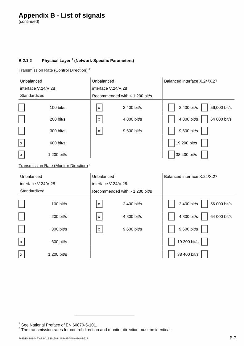
B 2.1.2 Physical Layer 1 (Network-Specific Parameters)
Transmission Rate (Control Direction) 2
Unbalanced
interface V.24/V.28
Standardized
Unbalanced
interface V.24/V.28
Recommended with > 1 200 bit/s
Balanced interface X.24/X.27
100 bit/s x 2 400 bit/s 2 400 bit/s 56,000 bit/s
200 bit/s x 4 800 bit/s 4 800 bit/s 64 000 bit/s
300 bit/s x 9 600 bit/s 9 600 bit/s
x 600 bit/s 19 200 bit/s
x 1 200 bit/s 38 400 bit/s
Transmission Rate (Monitor Direction) 3
Unbalanced
interface V.24/V.28
Standardized
Unbalanced
interface V.24/V.28
Recommended with > 1 200 bit/s
Balanced interface X.24/X.27
100 bit/s x 2 400 bit/s 2 400 bit/s 56 000 bit/s 200 bit/s x 4 800 bit/s 4 800 bit/s 64 000 bit/s 300 bit/s x 9 600 bit/s 9 600 bit/s x 600 bit/s 19 200 bit/s x 1 200 bit/s 38 400 bit/s
1 See National Preface of EN 60870-5-101. 2 The transmission rates for control direction and monitor direction must be identical.
Appendix B - List of signals (continued)
B-8 P439/EN M/Bd4 // AFSV.12.10190 D /// P439-304-407/408-615
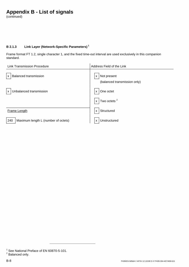
B 2.1.3 Link Layer (Network-Specific Parameters) 1
Frame format FT 1.2, single character 1, and the fixed time-out interval are used exclusively in this companion standard.
Link Transmission Procedure Address Field of the Link x Balanced transmission x Not present
(balanced transmission only) x Unbalanced transmission x One octet x Two octets 2 Frame Length x Structured 240 Maximum length L (number of octets) x Unstructured
1 See National Preface of EN 60870-5-101. 2 Balanced only.
Appendix B - List of signals (continued)
P439/EN M/Bd4 // AFSV.12.10190 D /// P439-304-407/408-615 B-9
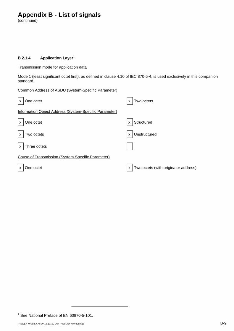
B 2.1.4 Application Layer1
Transmission mode for application data
Mode 1 (least significant octet first), as defined in clause 4.10 of IEC 870-5-4, is used exclusively in this companion standard.
Common Address of ASDU (System-Specific Parameter)
x One octet x Two octets
Information Object Address (System-Specific Parameter)
x One octet x Structured x Two octets x Unstructured x Three octets
Cause of Transmission (System-Specific Parameter)
x One octet x Two octets (with originator address)
1 See National Preface of EN 60870-5-101.
Appendix B - List of signals (continued)
B-10 P439/EN M/Bd4 // AFSV.12.10190 D /// P439-304-407/408-615
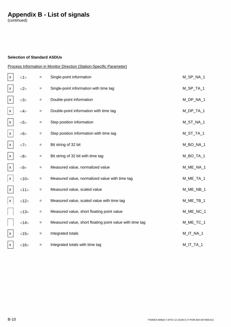
Selection of Standard ASDUs
Process Information in Monitor Direction (Station-Specific Parameter)
x <1> = Single-point information M_SP_NA_1
x <2> = Single-point information with time tag M_SP_TA_1
x <3> = Double-point information M_DP_NA_1
x <4> = Double-point information with time tag M_DP_TA_1
x <5> = Step position information M_ST_NA_1
x <6> = Step position information with time tag M_ST_TA_1
x <7> = Bit string of 32 bit M_BO_NA_1
x <8> = Bit string of 32 bit with time tag M_BO_TA_1
x <9> = Measured value, normalized value M_ME_NA_1
x <10> = Measured value, normalized value with time tag M_ME_TA_1
x <11> = Measured value, scaled value M_ME_NB_1
x <12> = Measured value, scaled value with time tag M_ME_TB_1
<13> = Measured value, short floating point value M_ME_NC_1
<14> = Measured value, short floating point value with time tag M_ME_TC_1
x <15> = Integrated totals M_IT_NA_1
x <16> = Integrated totals with time tag M_IT_TA_1

Appendix B - List of signals (continued)
P439/EN M/Bd4 // AFSV.12.10190 D /// P439-304-407/408-615 B-11
x <17> = Event of protection equipment with time tag M_EP_TA_1
x <18> = Packed start events of protection equipment with time tag ME_EP_TB_1
x <19> = Packed output circuit information of protection equipment with time tag M_EP_TC_1
<20> = Packed single-point information with status change detection M_PS_NA_1
<21> = Measured value, normalized value without quality descriptor M_ME_ND_1
Appendix B - List of signals (continued)
B-12 P439/EN M/Bd4 // AFSV.12.10190 D /// P439-304-407/408-615
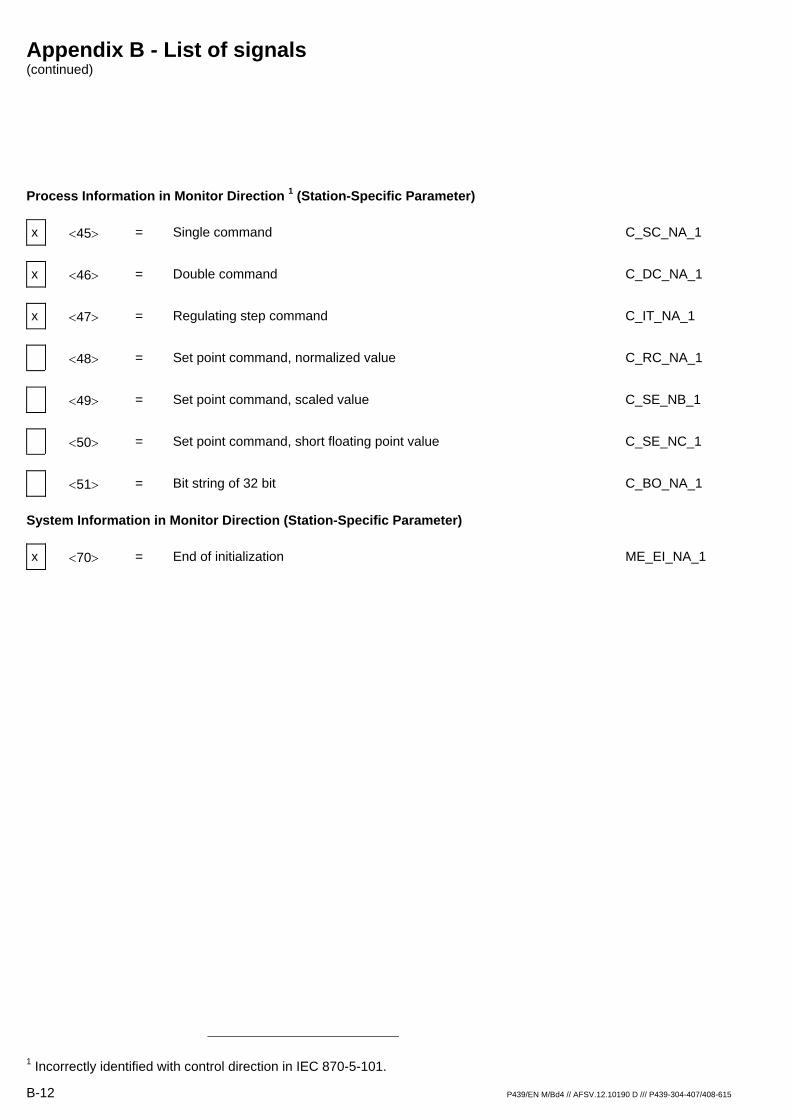
Process Information in Monitor Direction 1 (Station-Specific Parameter)
x <45> = Single command C_SC_NA_1 x <46> = Double command C_DC_NA_1 x <47> = Regulating step command C_IT_NA_1 <48> = Set point command, normalized value C_RC_NA_1 <49> = Set point command, scaled value C_SE_NB_1 <50> = Set point command, short floating point value C_SE_NC_1 <51> = Bit string of 32 bit C_BO_NA_1
System Information in Monitor Direction (Station-Specific Parameter)
x <70> = End of initialization ME_EI_NA_1
1 Incorrectly identified with control direction in IEC 870-5-101.
Appendix B - List of signals (continued)
P439/EN M/Bd4 // AFSV.12.10190 D /// P439-304-407/408-615 B-13
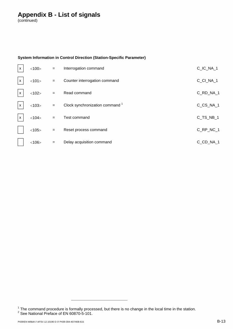
System Information in Control Direction (Station-Specific Parameter)
x <100> = Interrogation command C_IC_NA_1 x <101> = Counter interrogation command C_CI_NA_1 x <102> = Read command C_RD_NA_1 x <103> = Clock synchronization command 1 C_CS_NA_1 x <104> = Test command C_TS_NB_1 <105> = Reset process command C_RP_NC_1 <106> = Delay acquisition command C_CD_NA_1
1 The command procedure is formally processed, but there is no change in the local time in the station. 2 See National Preface of EN 60870-5-101.
Appendix B - List of signals (continued)
B-14 P439/EN M/Bd4 // AFSV.12.10190 D /// P439-304-407/408-615
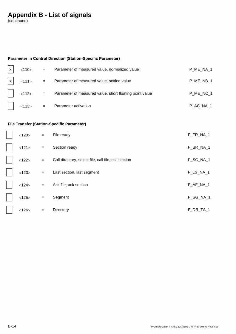
Parameter in Control Direction (Station-Specific Parameter)
x <110> = Parameter of measured value, normalized value P_ME_NA_1
x <111> = Parameter of measured value, scaled value P_ME_NB_1 <112> = Parameter of measured value, short floating point value P_ME_NC_1 <113> = Parameter activation P_AC_NA_1
File Transfer (Station-Specific Parameter)
<120> = File ready F_FR_NA_1 <121> = Section ready F_SR_NA_1 <122> = Call directory, select file, call file, call section F_SC_NA_1 <123> = Last section, last segment F_LS_NA_1 <124> = Ack file, ack section F_AF_NA_1 <125> = Segment F_SG_NA_1 <126> = Directory F_DR_TA_1

Appendix B - List of signals (continued)
P439/EN M/Bd4 // AFSV.12.10190 D /// P439-304-407/408-615 B-15
B 2.1.5 Basic Application Functions1
Station Initialization (Station-Specific Parameter)
x Remote initialization
General Interrogation (System- or Station-Specific Parameter)
x Global
x Group 1 x Group 7 x Group 13 x Group 2 x Group 8 x Group 14 x Group 3 x Group 9 x Group 15 x Group 4 x Group 10 x Group 16 x Group 5 x Group 11 x Group 6 x Group 12 Addresses per group have to be defined.
Clock Synchronization (Station-Specific Parameter)
x Clock synchronization
1 See National Preface of EN 60870-5-101.
Appendix B - List of signals (continued)
B-16 P439/EN M/Bd4 // AFSV.12.10190 D /// P439-304-407/408-615
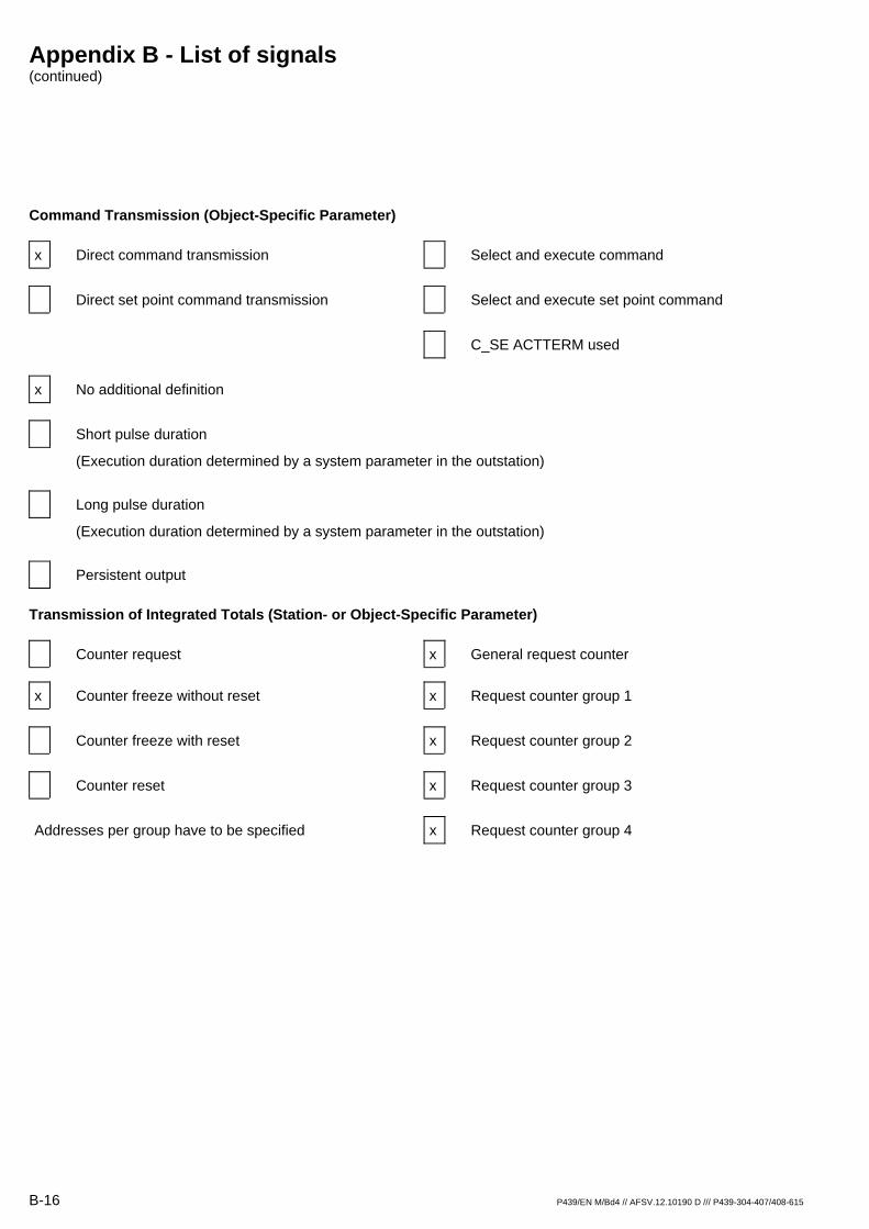
Command Transmission (Object-Specific Parameter)
x Direct command transmission Select and execute command Direct set point command transmission Select and execute set point command C_SE ACTTERM used x No additional definition
Short pulse duration
(Execution duration determined by a system parameter in the outstation) Long pulse duration
(Execution duration determined by a system parameter in the outstation) Persistent output
Transmission of Integrated Totals (Station- or Object-Specific Parameter)
Counter request x General request counter
x Counter freeze without reset x Request counter group 1 Counter freeze with reset x Request counter group 2 Counter reset x Request counter group 3 Addresses per group have to be specified x Request counter group 4

Appendix B - List of signals (continued)
P439/EN M/Bd4 // AFSV.12.10190 D /// P439-304-407/408-615 B-17
Parameter Loading (Object-Specific Parameter)
x Threshold value
Smoothing value Low limit for transmission of measured value High limit for transmission of measured value
Parameter Activation (Object-Specific Parameter)
Act/deact of persistent cyclic or periodic transmission of the addressed object
File Transfer (Station-Specific Parameter)
File transfer in monitor direction F_FR_NA_1 File transfer in control direction F_FR_NA_1
Appendix B - List of signals (continued)
B-18 P439/EN M/Bd4 // AFSV.12.10190 D /// P439-304-407/408-615
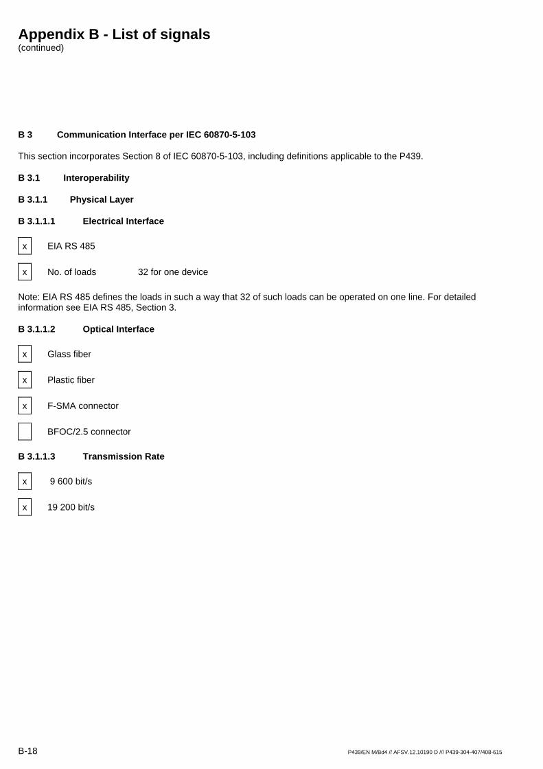
B 3 Communication Interface per IEC 60870-5-103
This section incorporates Section 8 of IEC 60870-5-103, including definitions applicable to the P439.
B 3.1 Interoperability
B 3.1.1 Physical Layer
B 3.1.1.1 Electrical Interface
x EIA RS 485
x No. of loads 32 for one device
Note: EIA RS 485 defines the loads in such a way that 32 of such loads can be operated on one line. For detailed information see EIA RS 485, Section 3.
B 3.1.1.2 Optical Interface
x Glass fiber
x Plastic fiber
x F-SMA connector
BFOC/2.5 connector
B 3.1.1.3 Transmission Rate
x 9 600 bit/s
x 19 200 bit/s
Appendix B - List of signals (continued)
P439/EN M/Bd4 // AFSV.12.10190 D /// P439-304-407/408-615 B-19
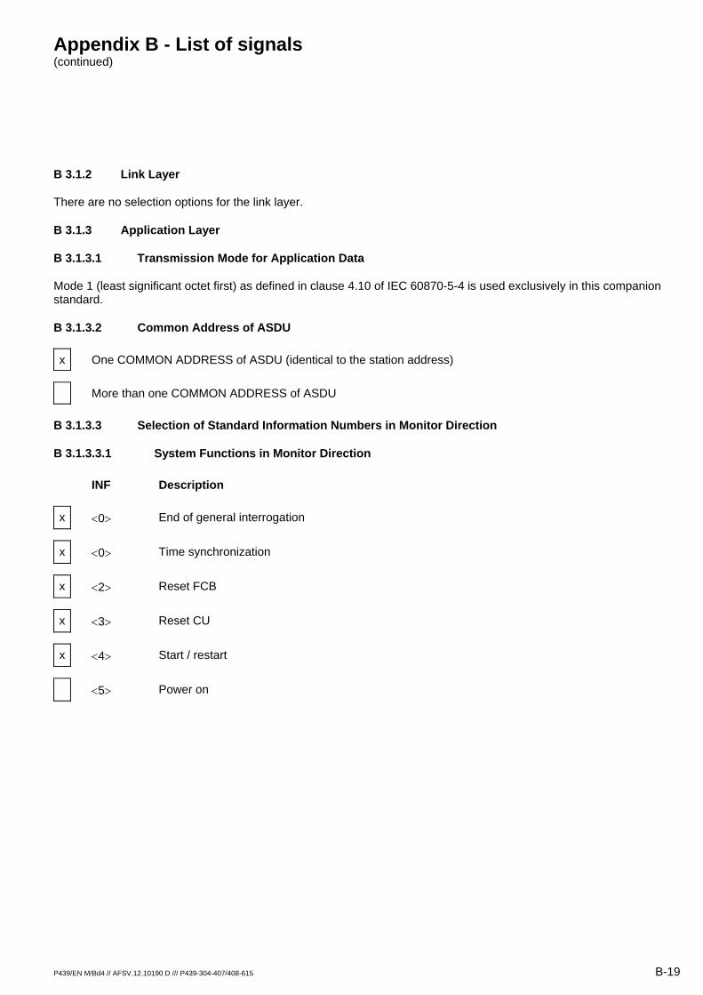
B 3.1.2 Link Layer
There are no selection options for the link layer.
B 3.1.3 Application Layer
B 3.1.3.1 Transmission Mode for Application Data
Mode 1 (least significant octet first) as defined in clause 4.10 of IEC 60870-5-4 is used exclusively in this companion standard.
B 3.1.3.2 Common Address of ASDU
x One COMMON ADDRESS of ASDU (identical to the station address)
More than one COMMON ADDRESS of ASDU
B 3.1.3.3 Selection of Standard Information Numbers in Monitor Direction
B 3.1.3.3.1 System Functions in Monitor Direction
INF Description
x <0> End of general interrogation
x <0> Time synchronization
x <2> Reset FCB
x <3> Reset CU
x <4> Start / restart
<5> Power on
Appendix B - List of signals (continued)
B-20 P439/EN M/Bd4-S // AFSV.12.10190 D /// P439-304-407/408-615
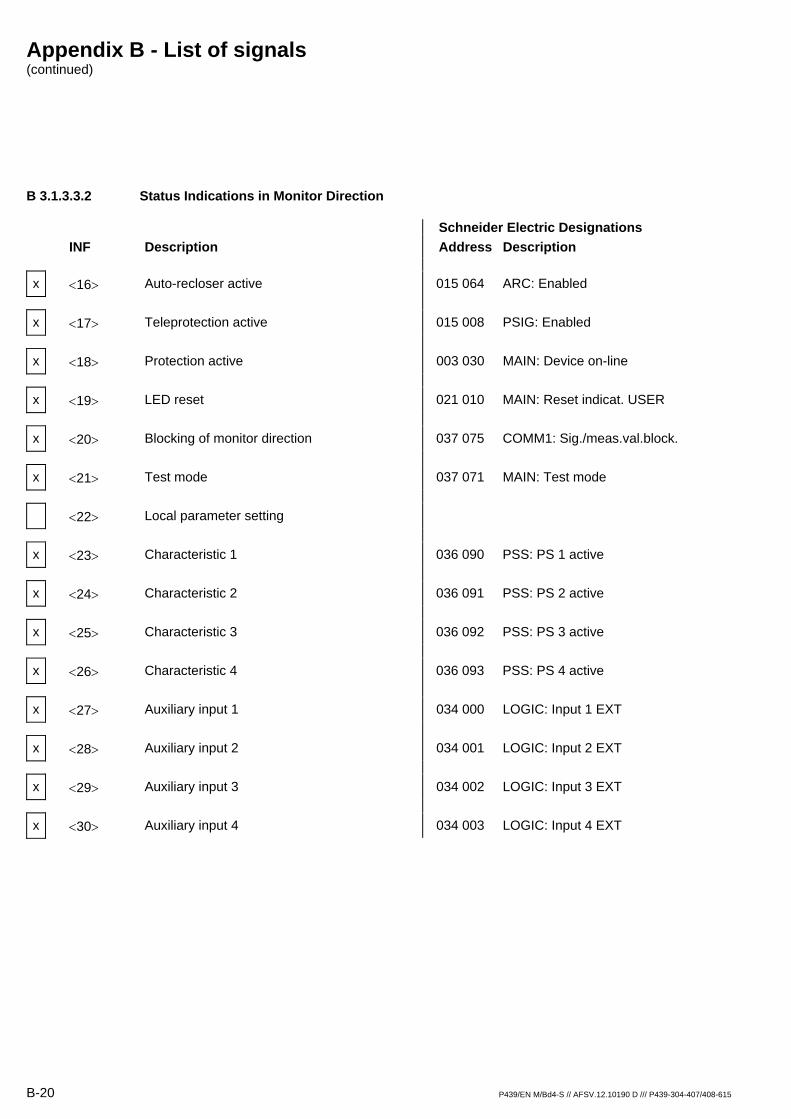
B 3.1.3.3.2 Status Indications in Monitor Direction
Schneider Electric Designations INF Description Address Description
x <16> Auto-recloser active 015 064 ARC: Enabled
x <17> Teleprotection active 015 008 PSIG: Enabled
x <18> Protection active 003 030 MAIN: Device on-line
x <19> LED reset 021 010 MAIN: Reset indicat. USER
x <20> Blocking of monitor direction 037 075 COMM1: Sig./meas.val.block.
x <21> Test mode 037 071 MAIN: Test mode
<22> Local parameter setting
x <23> Characteristic 1 036 090 PSS: PS 1 active
x <24> Characteristic 2 036 091 PSS: PS 2 active
x <25> Characteristic 3 036 092 PSS: PS 3 active
x <26> Characteristic 4 036 093 PSS: PS 4 active
x <27> Auxiliary input 1 034 000 LOGIC: Input 1 EXT
x <28> Auxiliary input 2 034 001 LOGIC: Input 2 EXT
x <29> Auxiliary input 3 034 002 LOGIC: Input 3 EXT
x <30> Auxiliary input 4 034 003 LOGIC: Input 4 EXT

Appendix B - List of signals (continued)
P439/EN M/Bd4-S // AFSV.12.10190 D /// P439-304-407/408-615 B-21
B 3.1.3.3.3 Monitoring Signals (Supervision Indications) in Monitor Direction
Schneider Electric Designations INF Description Address Description
x <32> Measured value supervision I 040 087 MCMON: Meas. circ. I faulty
x <33> Measured value supervision V 038 023 MCMON: Meas. circ. V faulty
x <35> Phase sequence supervision 038 049 MCMON: Phase sequ. V faulty
x <36>1 Trip circuit supervision 041 200 SFMON: Relay Kxx faulty
x <37> I>> back-up operation 037 021 BUOC: Active
x <38> VT fuse failure 004 061 MAIN: M.c.b. trip V EXT
x <39> Teleprotection disturbed 036 060 PSIG: Telecom. faulty
x <46> Group warning 036 100 SFMON: Warning (relay)
x <47> Group alarm 004 065 MAIN: Blocked/Faulty
1 The message content is formed from the OR operation of the individual signals.
Appendix B - List of signals (continued)
B-22 P439/EN M/Bd4-S // AFSV.12.10190 D /// P439-304-407/408-615
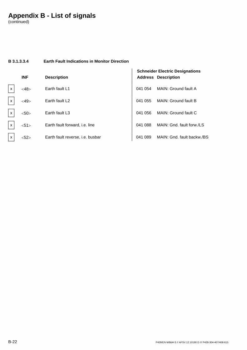
B 3.1.3.3.4 Earth Fault Indications in Monitor Direction
Schneider Electric Designations INF Description Address Description
x <48> Earth fault L1 041 054 MAIN: Ground fault A
x <49> Earth fault L2 041 055 MAIN: Ground fault B
x <50> Earth fault L3 041 056 MAIN: Ground fault C
x <51> Earth fault forward, i.e. line 041 088 MAIN: Gnd. fault forw./LS
x <52> Earth fault reverse, i.e. busbar 041 089 MAIN: Gnd. fault backw./BS
Appendix B - List of signals (continued)
P439/EN M/Bd4-S // AFSV.12.10190 D /// P439-304-407/408-615 B-23
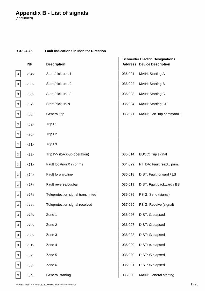
B 3.1.3.3.5 Fault Indications in Monitor Direction
Schneider Electric Designations INF Description Address Device Description
x <64> Start /pick-up L1 036 001 MAIN: Starting A
x <65> Start /pick-up L2 036 002 MAIN: Starting B
x <66> Start /pick-up L3 036 003 MAIN: Starting C
x <67> Start /pick-up N 036 004 MAIN: Starting GF
x <68> General trip 036 071 MAIN: Gen. trip command 1
x <69> Trip L1
x <70> Trip L2
x <71> Trip L3
x <72> Trip I>> (back-up operation) 036 014 BUOC: Trip signal
x <73> Fault location X in ohms 004 029 FT_DA: Fault react., prim.
x <74> Fault forward/line 036 018 DIST: Fault forward / LS
x <75> Fault reverse/busbar 036 019 DIST: Fault backward / BS
x <76> Teleprotection signal transmitted 036 035 PSIG: Send (signal)
x <77> Teleprotection signal received 037 029 PSIG: Receive (signal)
x <78> Zone 1 036 026 DIST: t1 elapsed
x <79> Zone 2 036 027 DIST: t2 elapsed
x <80> Zone 3 036 028 DIST: t3 elapsed
x <81> Zone 4 036 029 DIST: t4 elapsed
x <82> Zone 5 036 030 DIST: t5 elapsed
x <83> Zone 6 036 031 DIST: t6 elapsed
x <84> General starting 036 000 MAIN: General starting
Appendix B - List of signals (continued)
B-24 P439/EN M/Bd4-S // AFSV.12.10190 D /// P439-304-407/408-615
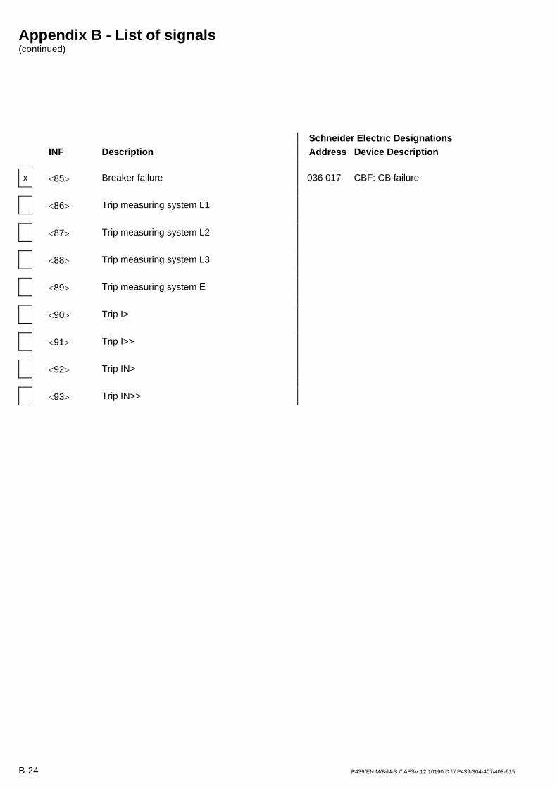
Schneider Electric Designations INF Description Address Device Description
x <85> Breaker failure 036 017 CBF: CB failure
<86> Trip measuring system L1
<87> Trip measuring system L2
<88> Trip measuring system L3
<89> Trip measuring system E
<90> Trip I>
<91> Trip I>>
<92> Trip IN>
<93> Trip IN>>
Appendix B - List of signals (continued)
P439/EN M/Bd4-S // AFSV.12.10190 D /// P439-304-407/408-615 B-25
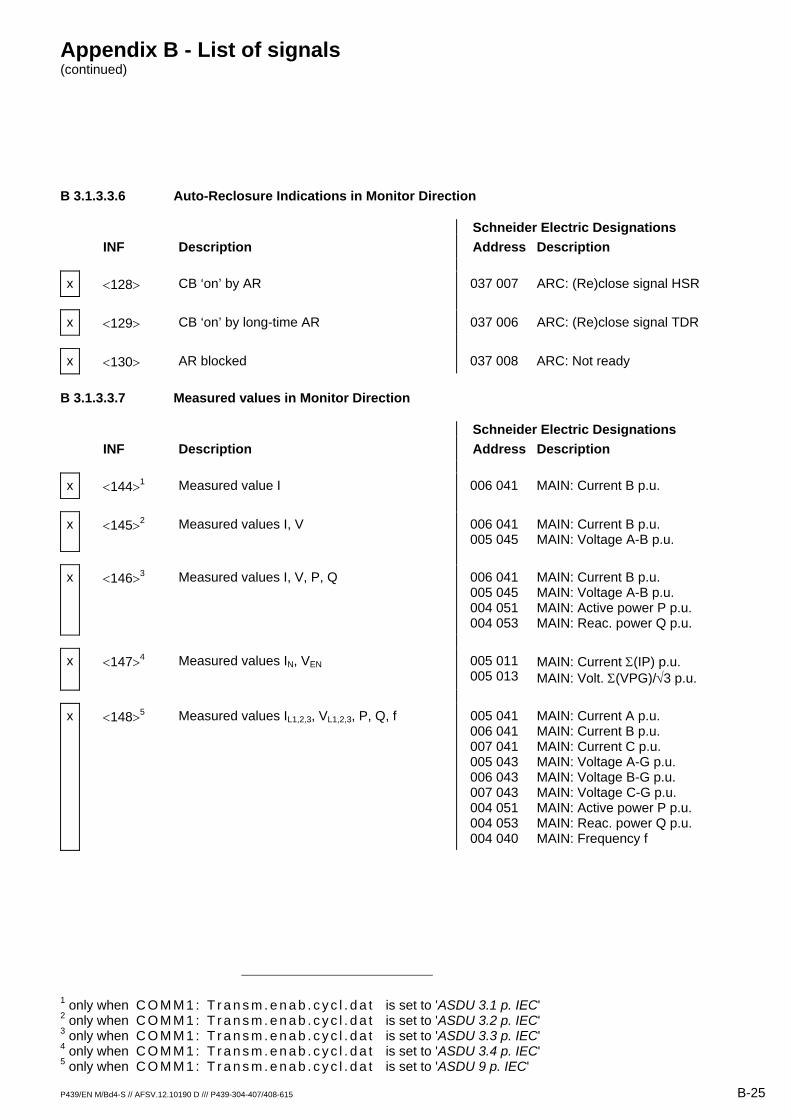
B 3.1.3.3.6 Auto-Reclosure Indications in Monitor Direction
Schneider Electric Designations INF Description Address Description
x <128> CB ‘on’ by AR 037 007 ARC: (Re)close signal HSR
x <129> CB ‘on’ by long-time AR 037 006 ARC: (Re)close signal TDR
x <130> AR blocked 037 008 ARC: Not ready
B 3.1.3.3.7 Measured values in Monitor Direction
Schneider Electric Designations INF Description Address Description
x <144>1 Measured value I 006 041 MAIN: Current B p.u.
x <145>2 Measured values I, V 006 041 005 045
MAIN: Current B p.u. MAIN: Voltage A-B p.u.
x <146>3 Measured values I, V, P, Q 006 041 005 045 004 051 004 053
MAIN: Current B p.u. MAIN: Voltage A-B p.u. MAIN: Active power P p.u. MAIN: Reac. power Q p.u.
x <147>4 Measured values IN, VEN 005 011 005 013
MAIN: Current Σ(IP) p.u. MAIN: Volt. Σ(VPG)/√3 p.u.
x <148>5 Measured values IL1,2,3, VL1,2,3, P, Q, f 005 041 006 041 007 041 005 043 006 043 007 043 004 051 004 053 004 040
MAIN: Current A p.u. MAIN: Current B p.u. MAIN: Current C p.u. MAIN: Voltage A-G p.u. MAIN: Voltage B-G p.u. MAIN: Voltage C-G p.u. MAIN: Active power P p.u. MAIN: Reac. power Q p.u. MAIN: Frequency f
1 only when C O M M 1 : T r a n s m . e n a b . c y c l . d a t is set to 'ASDU 3.1 p. IEC' 2 only when C O M M 1 : T r a n s m . e n a b . c y c l . d a t is set to 'ASDU 3.2 p. IEC' 3 only when C O M M 1 : T r a n s m . e n a b . c y c l . d a t is set to 'ASDU 3.3 p. IEC' 4 only when C O M M 1 : T r a n s m . e n a b . c y c l . d a t is set to 'ASDU 3.4 p. IEC' 5 only when C O M M 1 : T r a n s m . e n a b . c y c l . d a t is set to 'ASDU 9 p. IEC'

Appendix B - List of signals (continued)
B-26 P439/EN M/Bd4-S // AFSV.12.10190 D /// P439-304-407/408-615
B 3.1.3.3.8 Generic Functions in Monitor Direction
INF Description
<240> Read headings of all defined groups
<241> Read values or attributes of all entries of one group
<243> Read directory of a single entry
<244> Read value or attribute of a single entry
<245> General interrogation of generic data
<249> Write entry with confirmation
<250> Write entry with execution
<251> Write entry abort
Appendix B - List of signals (continued)
P439/EN M/Bd4-S // AFSV.12.10190 D /// P439-304-407/408-615 B-27
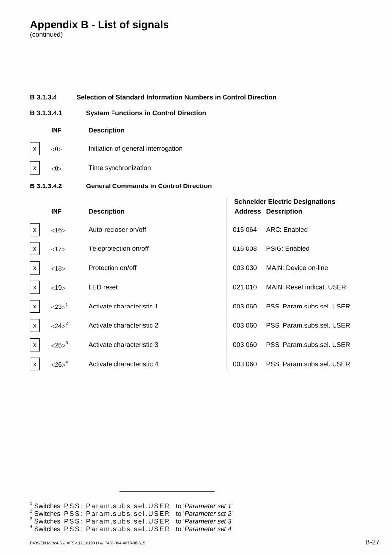
B 3.1.3.4 Selection of Standard Information Numbers in Control Direction
B 3.1.3.4.1 System Functions in Control Direction
INF Description
x <0> Initiation of general interrogation
x <0> Time synchronization
B 3.1.3.4.2 General Commands in Control Direction
Schneider Electric Designations INF Description Address Description
x <16> Auto-recloser on/off 015 064 ARC: Enabled
x <17> Teleprotection on/off 015 008 PSIG: Enabled
x <18> Protection on/off 003 030 MAIN: Device on-line
x <19> LED reset 021 010 MAIN: Reset indicat. USER
x <23>1 Activate characteristic 1 003 060 PSS: Param.subs.sel. USER
x <24>2 Activate characteristic 2 003 060 PSS: Param.subs.sel. USER
x <25>3 Activate characteristic 3 003 060 PSS: Param.subs.sel. USER
x <26>4 Activate characteristic 4 003 060 PSS: Param.subs.sel. USER
1 Switches P S S : P a r a m . s u b s . s e l . U S E R to 'Parameter set 1' 2 Switches P S S : P a r a m . s u b s . s e l . U S E R to 'Parameter set 2' 3 Switches P S S : P a r a m . s u b s . s e l . U S E R to 'Parameter set 3' 4 Switches P S S : P a r a m . s u b s . s e l . U S E R to 'Parameter set 4'
Appendix B - List of signals (continued)
B-28 P439/EN M/Bd4 // AFSV.12.10190 D /// P439-304-407/408-615
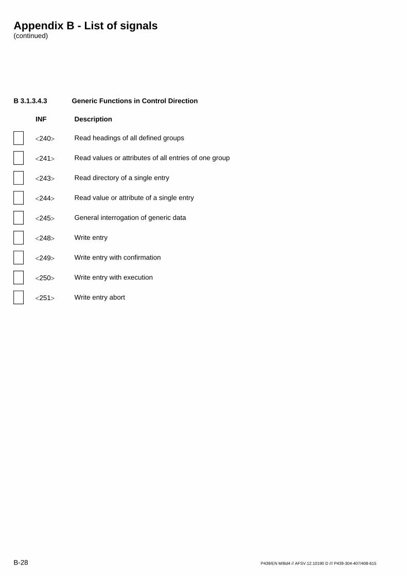
B 3.1.3.4.3 Generic Functions in Control Direction
INF Description
<240> Read headings of all defined groups
<241> Read values or attributes of all entries of one group
<243> Read directory of a single entry
<244> Read value or attribute of a single entry
<245> General interrogation of generic data
<248> Write entry
<249> Write entry with confirmation
<250> Write entry with execution
<251> Write entry abort

Appendix B - List of signals (continued)
P439/EN M/Bd4 // AFSV.12.10190 D /// P439-304-407/408-615 B-29
B 3.1.3.5 Basic Application Functions
x Test mode
x Blocking of monitor direction
x Disturbance data
Generic services
x Private data
B 3.1.3.6 Miscellaneous
Measured values are transmitted both with ASDU 3 and ASDU 9. As defined in Sec. 7.2.6.8, the maximum MVAL can be either 1.2 or 2.4 times the rated value. In ASDU 3 and ASDU 9, different ratings may not be used; in other words, there is only one choice for each measured value.
Measured value Max. MVAL = nom. value multiplied by
1.2 or 2.4
Current A x
Current B x
Current C x
Voltage A-G x
Voltage B-G x
Voltage C-G x
Enabled power P x
Reactive power Q x
Frequency f x
Voltage A-B x

B-30 P439/EN M/Bd4 // AFSV.12.10190 D /// P439-304-407/408-615
Appendix C - List of Bay Types
P439/EN M/Bd4 // AFSV.12.10190 D /// P439-304-407/408-615 C-1
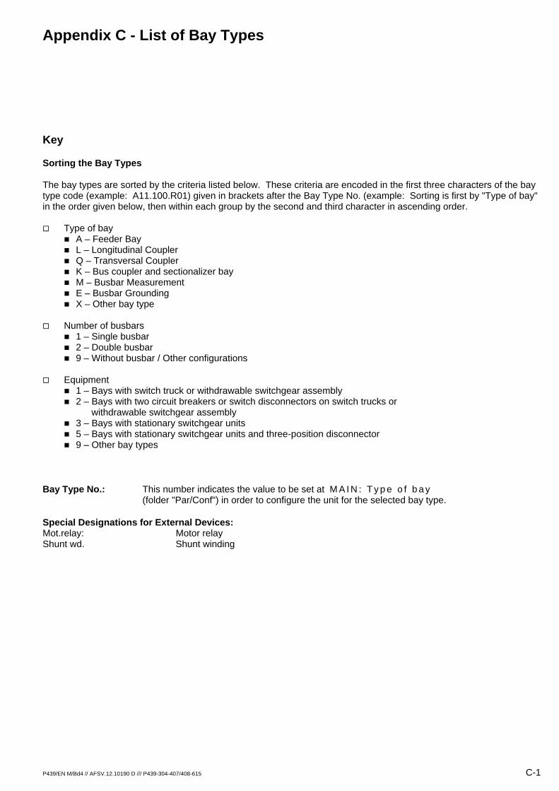
Key
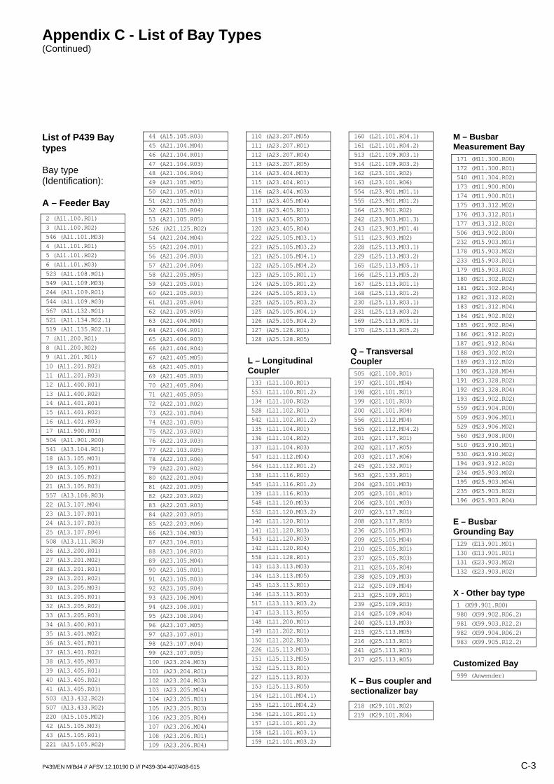
Sorting the Bay Types The bay types are sorted by the criteria listed below. These criteria are encoded in the first three characters of the bay type code (example: A11.100.R01) given in brackets after the Bay Type No. (example: Sorting is first by "Type of bay" in the order given below, then within each group by the second and third character in ascending order.
Type of bay A – Feeder Bay L – Longitudinal Coupler Q – Transversal Coupler K – Bus coupler and sectionalizer bay M – Busbar Measurement E – Busbar Grounding X – Other bay type
Number of busbars 1 – Single busbar 2 – Double busbar 9 – Without busbar / Other configurations
Equipment 1 – Bays with switch truck or withdrawable switchgear assembly 2 – Bays with two circuit breakers or switch disconnectors on switch trucks or withdrawable switchgear assembly 3 – Bays with stationary switchgear units 5 – Bays with stationary switchgear units and three-position disconnector 9 – Other bay types
Bay Type No.: This number indicates the value to be set at M A I N : T y p e o f b a y (folder "Par/Conf") in order to configure the unit for the selected bay type.
Special Designations for External Devices: Mot.relay: Motor relay Shunt wd. Shunt winding
Appendix C - List of Bay Types (Continued)
C-2 P439/EN M/Bd4 // AFSV.12.10190 D /// P439-304-407/408-615
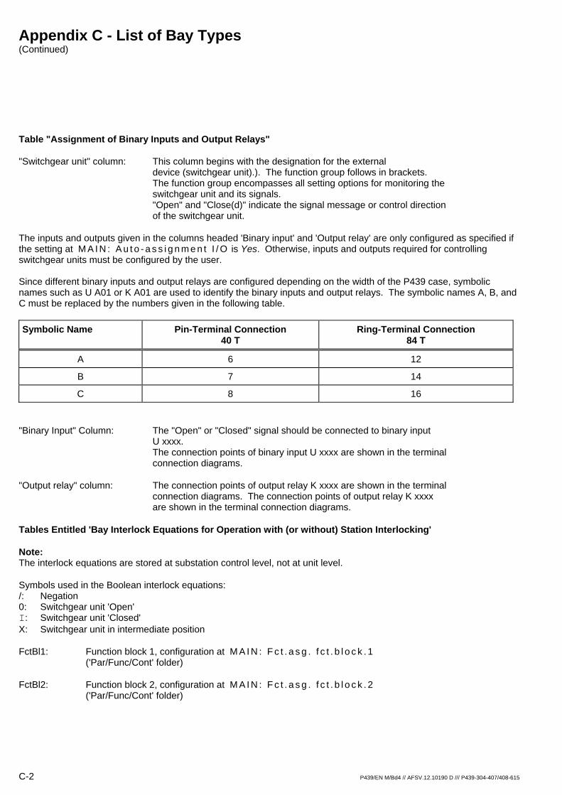
Table "Assignment of Binary Inputs and Output Relays"
"Switchgear unit" column: This column begins with the designation for the external device (switchgear unit).). The function group follows in brackets. The function group encompasses all setting options for monitoring the switchgear unit and its signals. "Open" and "Close(d)" indicate the signal message or control direction of the switchgear unit.
The inputs and outputs given in the columns headed 'Binary input' and 'Output relay' are only configured as specified if the setting at M A I N : A u t o - a s s i g n m e n t I / O is Yes. Otherwise, inputs and outputs required for controlling switchgear units must be configured by the user. Since different binary inputs and output relays are configured depending on the width of the P439 case, symbolic names such as U A01 or K A01 are used to identify the binary inputs and output relays. The symbolic names A, B, and C must be replaced by the numbers given in the following table.
Symbolic Name Pin-Terminal Connection 40 T
Ring-Terminal Connection 84 T
A 6 12
B 7 14
C 8 16
"Binary Input" Column: The "Open" or "Closed" signal should be connected to binary input U xxxx. The connection points of binary input U xxxx are shown in the terminal connection diagrams.
"Output relay" column: The connection points of output relay K xxxx are shown in the terminal connection diagrams. The connection points of output relay K xxxx are shown in the terminal connection diagrams.
Tables Entitled 'Bay Interlock Equations for Operation with (or without) Station Interlocking'
Note: The interlock equations are stored at substation control level, not at unit level.
Symbols used in the Boolean interlock equations: /: Negation 0: Switchgear unit 'Open' I: Switchgear unit 'Closed' X: Switchgear unit in intermediate position
FctBl1: Function block 1, configuration at M A I N : F c t . a s g . f c t . b l o c k . 1 ('Par/Func/Cont' folder)
FctBl2: Function block 2, configuration at M A I N : F c t . a s g . f c t . b l o c k . 2 ('Par/Func/Cont' folder)
Appendix C - List of Bay Types (Continued)
P439/EN M/Bd4 // AFSV.12.10190 D /// P439-304-407/408-615 C-3
List of P439 Bay types
Bay type (Identification):
A – Feeder Bay 2 (A11.100.R01)
3 (A11.100.R02)
546 (A11.101.M03)
4 (A11.101.R01)
5 (A11.101.R02)
6 (A11.101.R03)
523 (A11.108.R01)
549 (A11.109.M03) 244 (A11.109.R01) 544 (A11.109.R03) 567 (A11.132.R01) 521 (A11.134.R02.1) 519 (A11.135.R02.1) 7 (A11.200.R01)
8 (A11.200.R02)
9 (A11.201.R01)
10 (A11.201.R02)
11 (A11.201.R03)
12 (A11.400.R01)
13 (A11.400.R02)
14 (A11.401.R01)
15 (A11.401.R02)
16 (A11.401.R03)
17 (A11.900.R01)
504 (A11.901.R00)
541 (A13.104.R01)
18 (A13.105.M03) 19 (A13.105.R01)
20 (A13.105.R02)
21 (A13.105.R03)
557 (A13.106.R03)
22 (A13.107.M04) 23 (A13.107.R01) 24 (A13.107.R03) 25 (A13.107.R04) 508 (A13.111.R03) 26 (A13.200.R01)
27 (A13.201.M02) 28 (A13.201.R01)
29 (A13.201.R02)
30 (A13.205.M03) 31 (A13.205.R01)
32 (A13.205.R02)
33 (A13.205.R03)
34 (A13.400.R01)
35 (A13.401.M02) 36 (A13.401.R01)
37 (A13.401.R02)
38 (A13.405.M03) 39 (A13.405.R01)
40 (A13.405.R02)
41 (A13.405.R03)
503 (A13.432.R02)
507 (A13.433.R02)
220 (A15.105.M02) 42 (A15.105.M03) 43 (A15.105.R01)
221 (A15.105.R02)
44 (A15.105.R03)
45 (A21.104.M04) 46 (A21.104.R01) 47 (A21.104.R03) 48 (A21.104.R04) 49 (A21.105.M05) 50 (A21.105.R01) 51 (A21.105.R03) 52 (A21.105.R04) 53 (A21.105.R05) 526 (A21.125.R02) 54 (A21.204.M04) 55 (A21.204.R01) 56 (A21.204.R03) 57 (A21.204.R04) 58 (A21.205.M05) 59 (A21.205.R01) 60 (A21.205.R03) 61 (A21.205.R04) 62 (A21.205.R05) 63 (A21.404.M04) 64 (A21.404.R01) 65 (A21.404.R03) 66 (A21.404.R04) 67 (A21.405.M05) 68 (A21.405.R01) 69 (A21.405.R03) 70 (A21.405.R04) 71 (A21.405.R05) 72 (A22.101.R02) 73 (A22.101.R04) 74 (A22.101.R05) 75 (A22.103.R02) 76 (A22.103.R03) 77 (A22.103.R05) 78 (A22.103.R06) 79 (A22.201.R02) 80 (A22.201.R04) 81 (A22.201.R05) 82 (A22.203.R02) 83 (A22.203.R03) 84 (A22.203.R05) 85 (A22.203.R06) 86 (A23.104.M03) 87 (A23.104.R01)
88 (A23.104.R03)
89 (A23.105.M04) 90 (A23.105.R01) 91 (A23.105.R03) 92 (A23.105.R04) 93 (A23.106.M04) 94 (A23.106.R01) 95 (A23.106.R04) 96 (A23.107.M05) 97 (A23.107.R01) 98 (A23.107.R04) 99 (A23.107.R05) 100 (A23.204.M03) 101 (A23.204.R01)
102 (A23.204.R03)
103 (A23.205.M04) 104 (A23.205.R01) 105 (A23.205.R03) 106 (A23.205.R04) 107 (A23.206.M04) 108 (A23.206.R01) 109 (A23.206.R04)
110 (A23.207.M05) 111 (A23.207.R01) 112 (A23.207.R04) 113 (A23.207.R05) 114 (A23.404.M03) 115 (A23.404.R01)
116 (A23.404.R03)
117 (A23.405.M04) 118 (A23.405.R01) 119 (A23.405.R03) 120 (A23.405.R04) 222 (A25.105.M03.1) 223 (A25.105.M03.2) 121 (A25.105.M04.1) 122 (A25.105.M04.2) 123 (A25.105.R01.1) 124 (A25.105.R01.2) 224 (A25.105.R03.1) 225 (A25.105.R03.2) 125 (A25.105.R04.1) 126 (A25.105.R04.2) 127 (A25.128.R01) 128 (A25.128.R05)
L – Longitudinal Coupler 133 (L11.100.R01)
553 (L11.100.R01.2)
134 (L11.100.R02)
528 (L11.102.R01)
542 (L11.102.R01.2)
135 (L11.104.R01)
136 (L11.104.R02)
137 (L11.104.R03)
547 (L11.112.M04) 564 (L11.112.R01.2) 138 (L11.116.R01)
545 (L11.116.R01.2)
139 (L11.116.R03)
548 (L11.120.M03) 552 (L11.120.M03.2) 140 (L11.120.R01) 141 (L11.120.R03) 543 (L11.120.R03) 142 (L11.120.R04) 558 (L11.128.R01) 143 (L13.113.M03) 144 (L13.113.M05) 145 (L13.113.R01) 146 (L13.113.R03) 517 (L13.113.R03.2) 147 (L13.113.R05) 148 (L11.200.R01)
149 (L11.202.R01)
150 (L11.202.R03)
226 (L15.113.M03) 151 (L15.113.M05) 152 (L15.113.R01) 227 (L15.113.R03) 153 (L15.113.R05) 154 (L21.101.M04.1) 155 (L21.101.M04.2) 156 (L21.101.R01.1) 157 (L21.101.R01.2) 158 (L21.101.R03.1) 159 (L21.101.R03.2)
160 (L21.101.R04.1) 161 (L21.101.R04.2) 513 (L21.109.R03.1) 514 (L21.109.R03.2) 162 (L23.101.R02) 163 (L23.101.R06) 554 (L23.901.M01.1) 555 (L23.901.M01.2) 164 (L23.901.R02)
242 (L23.903.M01.3) 243 (L23.903.M01.4) 511 (L23.903.M02) 228 (L25.113.M03.1) 229 (L25.113.M03.2) 165 (L25.113.M05.1) 166 (L25.113.M05.2) 167 (L25.113.R01.1) 168 (L25.113.R01.2) 230 (L25.113.R03.1) 231 (L25.113.R03.2) 169 (L25.113.R05.1) 170 (L25.113.R05.2)
Q – Transversal Coupler 505 (Q21.100.R01)
197 (Q21.101.M04) 198 (Q21.101.R01) 199 (Q21.101.R03) 200 (Q21.101.R04) 556 (Q21.112.M04) 565 (Q21.112.M04.2) 201 (Q21.117.R01) 202 (Q21.117.R05) 203 (Q21.117.R06) 245 (Q21.132.R01) 563 (Q21.133.R01)
204 (Q23.101.M03) 205 (Q23.101.R01)
206 (Q23.101.R03)
207 (Q23.117.R01) 208 (Q23.117.R05) 236 (Q25.105.M03) 209 (Q25.105.M04) 210 (Q25.105.R01) 237 (Q25.105.R03) 211 (Q25.105.R04) 238 (Q25.109.M03) 212 (Q25.109.M04) 213 (Q25.109.R01) 239 (Q25.109.R03) 214 (Q25.109.R04) 240 (Q25.113.M03) 215 (Q25.113.M05) 216 (Q25.113.R01) 241 (Q25.113.R03) 217 (Q25.113.R05)
K – Bus coupler and sectionalizer bay 218 (K29.101.R02) 219 (K29.101.R06)
M – Busbar Measurement Bay 171 (M11.300.R00)
172 (M11.300.R01)
540 (M11.304.R02)
173 (M11.900.R00)
174 (M11.900.R01)
175 (M13.312.M02) 176 (M13.312.R01)
177 (M13.312.R02)
506 (M13.902.R00)
232 (M15.903.M01) 178 (M15.903.M02) 233 (M15.903.R01)
179 (M15.903.R02)
180 (M21.302.R02) 181 (M21.302.R04) 182 (M21.312.R02) 183 (M21.312.R04) 184 (M21.902.R02) 185 (M21.902.R04) 186 (M21.912.R02) 187 (M21.912.R04) 188 (M23.302.R02)
189 (M23.312.R02)
190 (M23.328.M04) 191 (M23.328.R02) 192 (M23.328.R04) 193 (M23.902.R02)
559 (M23.904.R00)
509 (M23.906.M01) 529 (M23.906.M02) 560 (M23.908.R00)
510 (M23.910.M01) 530 (M23.910.M02) 194 (M23.912.R02)
234 (M25.903.M02) 195 (M25.903.M04) 235 (M25.903.R02) 196 (M25.903.R04)
E – Busbar Grounding Bay 129 (E13.901.M01) 130 (E13.901.R01)
131 (E23.903.M02) 132 (E23.903.R02)
X - Other bay type 1 (X99.901.R00)
980 (X99.902.R06.2) 981 (X99.903.R12.2) 982 (X99.904.R06.2) 983 (X99.905.R12.2)
Customized Bay 999 (Anwender)

Appendix C - List of Bay Types (Continued)
C-4 P439/EN M/Bd4 // AFSV.12.10190 D /// P439-304-407/408-615
Bay Type No. 2 (A11.100.R01) Feeder bay with circuit breaker, single busbar
Assignment of Binary Inputs and Output Relays
Switchgear Unit Binary Input Output Relay
Q0 (DEV01) X0 (DEV02)
Open Close(d) Open Close(d)
U A01 U A02 U A03 U A04
K A01 K A02 / /
Bay Interlock Equations for Operation without Station Interlocking
Switchgear Unit Control O/C Interlock Equation
Q0 Close(d) /(X0=X) & /(FctBl1=I) & /(FctBl2=I)
Bay Interlock Equations for Operation with Station Interlocking
Switchgear Unit Control O/C Interlock Equation
Q0 Close(d) /(X0=X) & /(FctBl1=I) & /(FctBl2=I)
Appendix C - List of Bay Types (continued)
P439/EN M/Bd4 // AFSV.12.10190 D /// P439-304-407/408-615 C-5
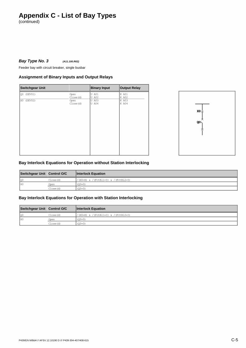
Bay Type No. 3 (A11.100.R02) Feeder bay with circuit breaker, single busbar
Assignment of Binary Inputs and Output Relays
Switchgear Unit Binary Input Output Relay
Q0 (DEV01) X0 (DEV02)
Open Close(d) Open Close(d)
U A01 U A02 U A03 U A04
K A01 K A02 K A03 K A04
Bay Interlock Equations for Operation without Station Interlocking
Switchgear Unit Control O/C Interlock Equation
Q0 Close(d) /(X0=X) & /(FctBl1=I) & /(FctBl2=I)
X0 Open (Q0=0)
Close(d) (Q0=0)
Bay Interlock Equations for Operation with Station Interlocking
Switchgear Unit Control O/C Interlock Equation
Q0 Close(d) /(X0=X) & /(FctBl1=I) & /(FctBl2=I)
X0 Open (Q0=0)
Close(d) (Q0=0)
Appendix C - List of Bay Types (continued)
C-6 P439/EN M/Bd4 // AFSV.12.10190 D /// P439-304-407/408-615
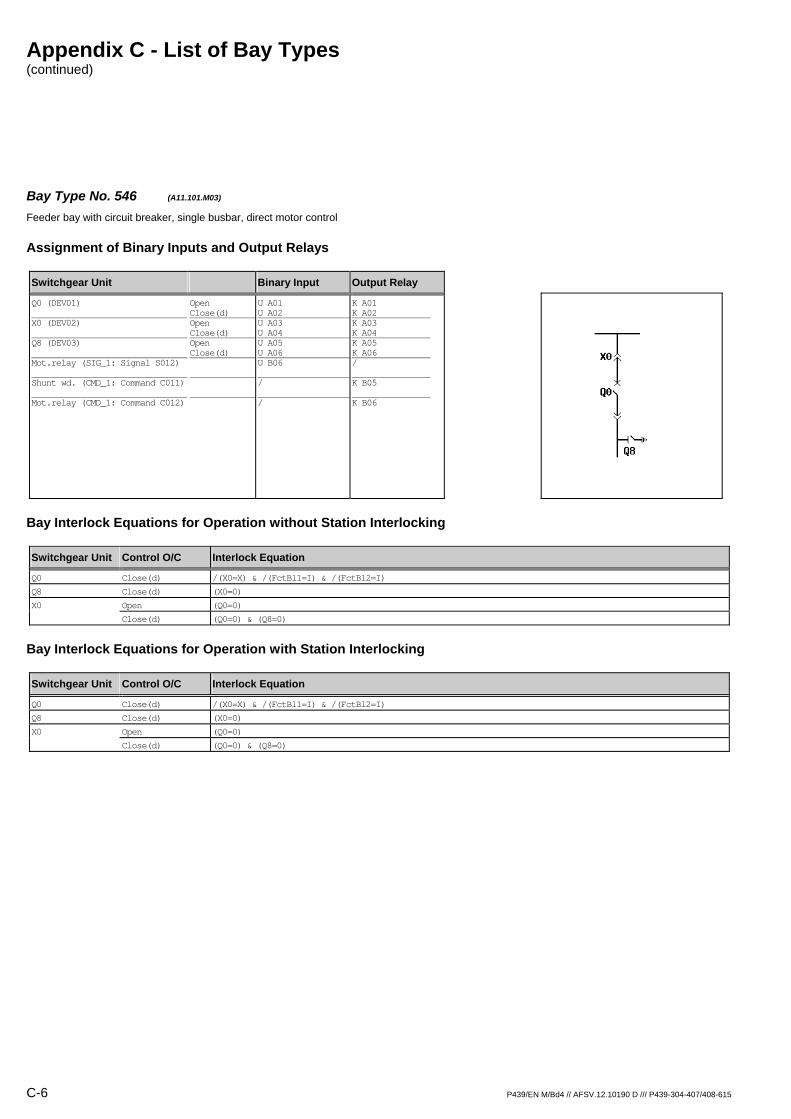
Bay Type No. 546 (A11.101.M03) Feeder bay with circuit breaker, single busbar, direct motor control
Assignment of Binary Inputs and Output Relays
Switchgear Unit Binary Input Output Relay
Q0 (DEV01) X0 (DEV02) Q8 (DEV03) Mot.relay (SIG_1: Signal S012) Shunt wd. (CMD_1: Command C011) Mot.relay (CMD_1: Command C012)
Open Close(d) Open Close(d) Open Close(d)
U A01 U A02 U A03 U A04 U A05 U A06 U B06 / /
K A01 K A02 K A03 K A04 K A05 K A06 / K B05 K B06
Bay Interlock Equations for Operation without Station Interlocking
Switchgear Unit Control O/C Interlock Equation
Q0 Close(d) /(X0=X) & /(FctBl1=I) & /(FctBl2=I)
Q8 Close(d) (X0=0)
X0 Open (Q0=0)
Close(d) (Q0=0) & (Q8=0)
Bay Interlock Equations for Operation with Station Interlocking
Switchgear Unit Control O/C Interlock Equation
Q0 Close(d) /(X0=X) & /(FctBl1=I) & /(FctBl2=I)
Q8 Close(d) (X0=0)
X0 Open (Q0=0)
Close(d) (Q0=0) & (Q8=0)

Appendix C - List of Bay Types (continued)
P439/EN M/Bd4 // AFSV.12.10190 D /// P439-304-407/408-615 C-7
Bay Type No. 4 (A11.101.R01) Feeder bay with circuit breaker, single busbar
Assignment of Binary Inputs and Output Relays
Switchgear Unit Binary Input Output Relay
Q0 (DEV01) X0 (DEV02) Q8 (DEV03)
Open Close(d) Open Close(d) Open Close(d)
U A01 U A02 U A03 U A04 U A05 U A06
K A01 K A02 / / / /
Bay Interlock Equations for Operation without Station Interlocking
Switchgear Unit Control O/C Interlock Equation
Q0 Close(d) /(X0=X) & /(FctBl1=I) & /(FctBl2=I)
Bay Interlock Equations for Operation with Station Interlocking
Switchgear Unit Control O/C Interlock Equation
Q0 Close(d) /(X0=X) & /(FctBl1=I) & /(FctBl2=I)

Appendix C - List of Bay Types (continued)
C-8 P439/EN M/Bd4 // AFSV.12.10190 D /// P439-304-407/408-615
Bay Type No. 5 (A11.101.R02) Feeder bay with circuit breaker, single busbar
Assignment of Binary Inputs and Output Relays
Switchgear Unit Binary Input Output Relay
Q0 (DEV01) X0 (DEV02) Q8 (DEV03)
Open Close(d) Open Close(d) Open Close(d)
U A01 U A02 U A03 U A04 U A05 U A06
K A01 K A02 K A03 K A04 / /
Bay Interlock Equations for Operation without Station Interlocking
Switchgear Unit Control O/C Interlock Equation
Q0 Close(d) /(X0=X) & /(FctBl1=I) & /(FctBl2=I)
X0 Open (Q0=0)
Close(d) (Q0=0) & (Q8=0)
Bay Interlock Equations for Operation with Station Interlocking
Switchgear Unit Control O/C Interlock Equation
Q0 Close(d) /(X0=X) & /(FctBl1=I) & /(FctBl2=I)
X0 Open (Q0=0)
Close(d) (Q0=0) & (Q8=0)

Appendix C - List of Bay Types (continued)
P439/EN M/Bd4 // AFSV.12.10190 D /// P439-304-407/408-615 C-9
Bay Type No. 6 (A11.101.R03) Feeder bay with circuit breaker, single busbar
Assignment of Binary Inputs and Output Relays
Switchgear Unit Binary Input Output Relay
Q0 (DEV01) X0 (DEV02) Q8 (DEV03)
Open Close(d) Open Close(d) Open Close(d)
U A01 U A02 U A03 U A04 U A05 U A06
K A01 K A02 K A03 K A04 K A05 K A06
Bay Interlock Equations for Operation without Station Interlocking
Switchgear Unit Control O/C Interlock Equation
Q0 Close(d) /(X0=X) & /(FctBl1=I) & /(FctBl2=I)
Q8 Close(d) (X0=0)
X0 Open (Q0=0)
Close(d) (Q0=0) & (Q8=0)
Bay Interlock Equations for Operation with Station Interlocking
Switchgear Unit Control O/C Interlock Equation
Q0 Close(d) /(X0=X) & /(FctBl1=I) & /(FctBl2=I)
Q8 Close(d) (X0=0)
X0 Open (Q0=0)
Close(d) (Q0=0) & (Q8=0)

Appendix C - List of Bay Types (continued)
C-10 P439/EN M/Bd4 // AFSV.12.10190 D /// P439-304-407/408-615
Bay Type No. 523 (A11.108.R01) Feeder bay with circuit breaker, single busbar
Assignment of Binary Inputs and Output Relays
Switchgear Unit Binary Input Output Relay
Q0 (DEV01) X0 (DEV02) Q15 (DEV03)
Open Close(d) Open Close(d) Open Close(d)
U A01 U A02 U A03 U A04 U A05 U A06
K A01 K A02 / / / /
Bay Interlock Equations for Operation without Station Interlocking
Switchgear Unit Control O/C Interlock Equation
Q0 Close(d) /(X0=X) & (Q15=0) & /(FctBl1=I) & /(FctBl2=I)
Bay Interlock Equations for Operation with Station Interlocking
Switchgear Unit Control O/C Interlock Equation
Q0 Close(d) /(X0=X) & (Q15=0) & /(FctBl1=I) & /(FctBl2=I)

Appendix C - List of Bay Types (continued)
P439/EN M/Bd4 // AFSV.12.10190 D /// P439-304-407/408-615 C-11
Bay Type No. 549 (A11.109.M03) Feeder bay with circuit breaker, single busbar, direct motor control
Assignment of Binary Inputs and Output Relays
Switchgear Unit Binary Input Output Relay
Q0 (DEV01) Q8 (DEV02) X0 (DEV03) Q15 (DEV04) Mot.relay (SIG_1: Signal S012) Shunt wd. (CMD_1: Command C011) Mot.relay (CMD_1: Command C012)
Open Close(d) Open Close(d) Open Close(d) Open Close(d)
U A01 U A02 U A03 U A04 U A05 U A06 U B01 U B02 U B06 / /
K A01 K A02 K A03 K A04 K A05 K A06 / / / K B05 K B06
Bay Interlock Equations for Operation without Station Interlocking
Switchgear Unit Control O/C Interlock Equation
Q0 Close(d) /(X0=X) & (Q15=0) & /(FctBl1=I) & /(FctBl2=I)
Q8 Close(d) (X0=0)
X0 Open (Q0=0)
Close(d) (Q0=0) & (Q8=0) & (Q15=0)
Bay Interlock Equations for Operation with Station Interlocking
Switchgear Unit Control O/C Interlock Equation
Q0 Close(d) /(X0=X) & (Q15=0) & /(FctBl1=I) & /(FctBl2=I)
Q8 Close(d) (X0=0)
X0 Open (Q0=0)
Close(d) (Q0=0) & (Q8=0) & (Q15=0)
Appendix C - List of Bay Types (continued)
C-12 P439/EN M/Bd4 // AFSV.12.10190 D /// P439-304-407/408-615
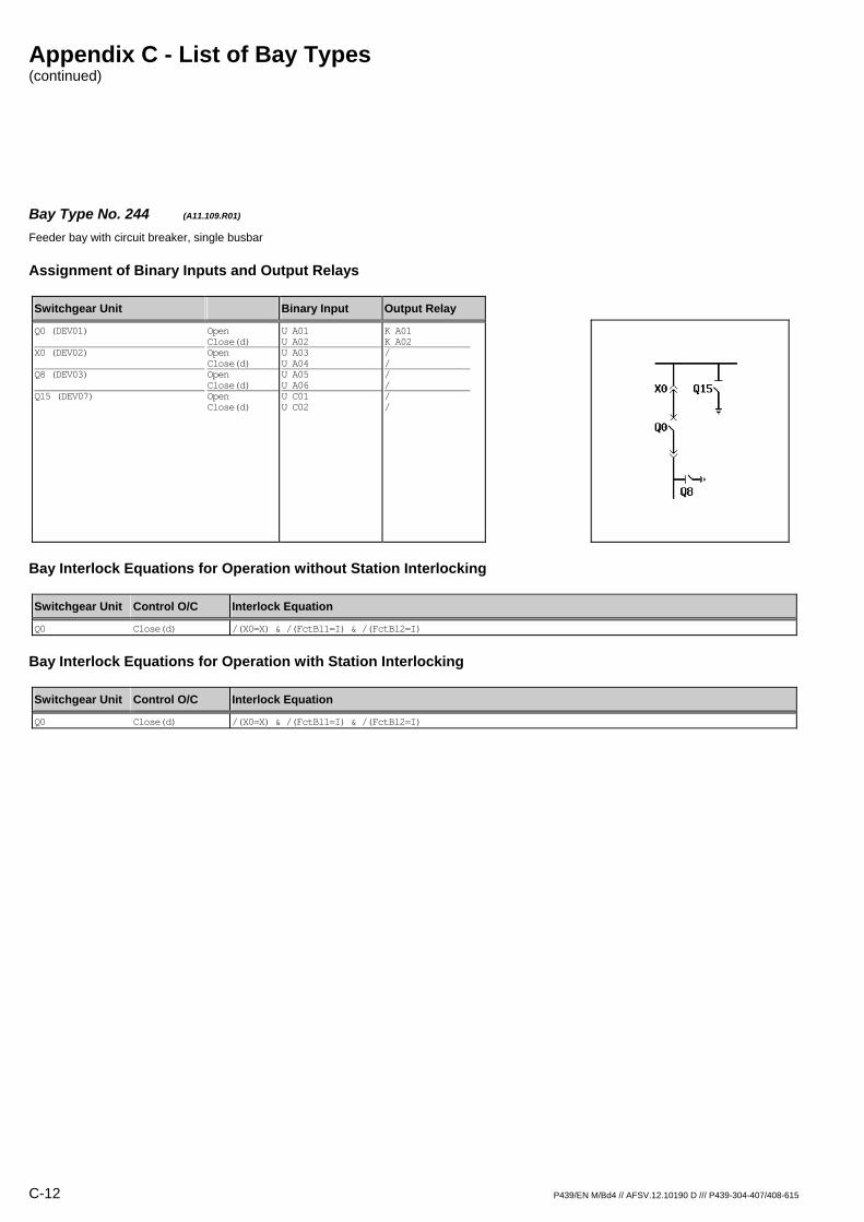
Bay Type No. 244 (A11.109.R01) Feeder bay with circuit breaker, single busbar
Assignment of Binary Inputs and Output Relays
Switchgear Unit Binary Input Output Relay
Q0 (DEV01) X0 (DEV02) Q8 (DEV03) Q15 (DEV07)
Open Close(d) Open Close(d) Open Close(d) Open Close(d)
U A01 U A02 U A03 U A04 U A05 U A06 U C01 U C02
K A01 K A02 / / / / / /
Bay Interlock Equations for Operation without Station Interlocking
Switchgear Unit Control O/C Interlock Equation
Q0 Close(d) /(X0=X) & /(FctBl1=I) & /(FctBl2=I)
Bay Interlock Equations for Operation with Station Interlocking
Switchgear Unit Control O/C Interlock Equation
Q0 Close(d) /(X0=X) & /(FctBl1=I) & /(FctBl2=I)

Appendix C - List of Bay Types (continued)
P439/EN M/Bd4 // AFSV.12.10190 D /// P439-304-407/408-615 C-13
Bay Type No. 544 (A11.109.R03) Feeder bay with circuit breaker, single busbar
Assignment of Binary Inputs and Output Relays
Switchgear Unit Binary Input Output Relay
Q0 (DEV01) X0 (DEV02) Q8 (DEV03) Q15 (DEV04)
Open Close(d) Open Close(d) Open Close(d) Open Close(d)
U A01 U A02 U A03 U A04 U A05 U A06 U B01 U B02
K A01 K A02 K A03 K A04 K A05 K A06 / /
Bay Interlock Equations for Operation without Station Interlocking
Switchgear Unit Control O/C Interlock Equation
Q0 Close(d) /(X0=X) & (Q15=0) & /(FctBl1=I) & /(FctBl2=I)
Q8 Close(d) (X0=0)
X0 Open (Q0=0)
Close(d) (Q0=0) & (Q8=0) & (Q15=0)
Bay Interlock Equations for Operation with Station Interlocking
Switchgear Unit Control O/C Interlock Equation
Q0 Close(d) /(X0=X) & (Q15=0) & /(FctBl1=I) & /(FctBl2=I)
Q8 Close(d) (X0=0)
X0 Open (Q0=0)
Close(d) (Q0=0) & (Q8=0) & (Q15=0)
Appendix C - List of Bay Types (continued)
C-14 P439/EN M/Bd4 // AFSV.12.10190 D /// P439-304-407/408-615
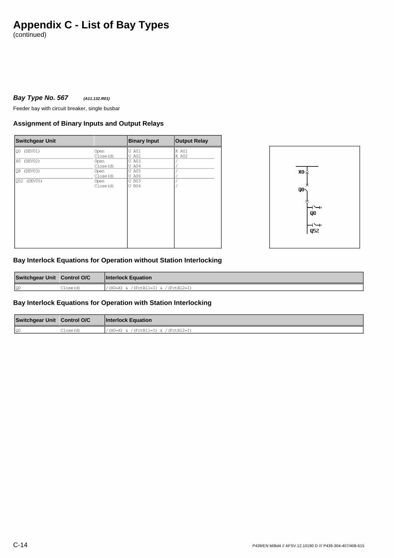
Bay Type No. 567 (A11.132.R01) Feeder bay with circuit breaker, single busbar
Assignment of Binary Inputs and Output Relays
Switchgear Unit Binary Input Output Relay
Q0 (DEV01) X0 (DEV02) Q8 (DEV03) Q52 (DEV05)
Open Close(d) Open Close(d) Open Close(d) Open Close(d)
U A01 U A02 U A03 U A04 U A05 U A06 U B03 U B04
K A01 K A02 / / / / / /
Bay Interlock Equations for Operation without Station Interlocking
Switchgear Unit Control O/C Interlock Equation
Q0 Close(d) /(X0=X) & /(FctBl1=I) & /(FctBl2=I)
Bay Interlock Equations for Operation with Station Interlocking
Switchgear Unit Control O/C Interlock Equation
Q0 Close(d) /(X0=X) & /(FctBl1=I) & /(FctBl2=I)
Appendix C - List of Bay Types (continued)
P439/EN M/Bd4 // AFSV.12.10190 D /// P439-304-407/408-615 C-15
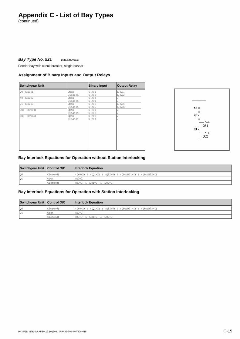
Bay Type No. 521 (A11.134.R02.1) Feeder bay with circuit breaker, single busbar
Assignment of Binary Inputs and Output Relays
Switchgear Unit Binary Input Output Relay
Q0 (DEV01) X0 (DEV02) Q1 (DEV03) Q81 (DEV04) Q82 (DEV05)
Open Close(d) Open Close(d) Open Close(d) Open Close(d) Open Close(d)
U A01 U A02 U A03 U A04 U A05 U A06 U B01 U B02 U B03 U B04
K A01 K A02 / / K A05 K A06 / / / /
Bay Interlock Equations for Operation without Station Interlocking
Switchgear Unit Control O/C Interlock Equation
Q0 Close(d) /(X0=X) & /(Q1=X) & (Q82=0) & /(FctBl1=I) & /(FctBl2=I)
Q1 Open (Q0=0)
Close(d) (Q0=0) & (Q81=0) & (Q82=0)
Bay Interlock Equations for Operation with Station Interlocking
Switchgear Unit Control O/C Interlock Equation
Q0 Close(d) /(X0=X) & /(Q1=X) & (Q82=0) & /(FctBl1=I) & /(FctBl2=I)
Q1 Open (Q0=0)
Close(d) (Q0=0) & (Q81=0) & (Q82=0)

Appendix C - List of Bay Types (continued)
C-16 P439/EN M/Bd4 // AFSV.12.10190 D /// P439-304-407/408-615
Bay Type No. 519 (A11.135.R02.1) Feeder bay with circuit breaker, single busbar
Assignment of Binary Inputs and Output Relays
Switchgear Unit Binary Input Output Relay
Q0 (DEV01) X0 (DEV02) Q1 (DEV03) Q81 (DEV04) Q82 (DEV05) Q15 (DEV06)
Open Close(d) Open Close(d) Open Close(d) Open Close(d) Open Close(d) Open Close(d)
U A01 U A02 U A03 U A04 U A05 U A06 U B01 U B02 U B03 U B04 U B05 U B06
K A01 K A02 / / K A05 K A06 / / / / / /
Bay Interlock Equations for Operation without Station Interlocking
Switchgear Unit Control O/C Interlock Equation
Q0 Close(d) /(X0=X) & /(Q1=X) & (Q15=0) & (Q82=0) & /(FctBl1=I) & /(FctBl2=I)
Q1 Open (Q0=0)
Close(d) (Q0=0) & (Q81=0) & (Q82=0)
Bay Interlock Equations for Operation with Station Interlocking
Switchgear Unit Control O/C Interlock Equation
Q0 Close(d) /(X0=X) & /(Q1=X) & (Q15=0) & (Q82=0) & /(FctBl1=I) & /(FctBl2=I)
Q1 Open (Q0=0)
Close(d) (Q0=0) & (Q81=0) & (Q82=0)

Appendix C - List of Bay Types (continued)
P439/EN M/Bd4 // AFSV.12.10190 D /// P439-304-407/408-615 C-17
Bay Type No. 7 (A11.200.R01) Feeder bay with switch disconnector, single busbar
Assignment of Binary Inputs and Output Relays
Switchgear Unit Binary Input Output Relay
Q0 (DEV01) X0 (DEV02)
Open Close(d) Open Close(d)
U A01 U A02 U A03 U A04
K A01 K A02 / /
Bay Interlock Equations for Operation without Station Interlocking
Switchgear Unit Control O/C Interlock Equation
Q0 Close(d) /(X0=X) & /(FctBl1=I) & /(FctBl2=I)
Bay Interlock Equations for Operation with Station Interlocking
Switchgear Unit Control O/C Interlock Equation
Q0 Close(d) /(X0=X) & /(FctBl1=I) & /(FctBl2=I)
Appendix C - List of Bay Types (continued)
C-18 P439/EN M/Bd4 // AFSV.12.10190 D /// P439-304-407/408-615
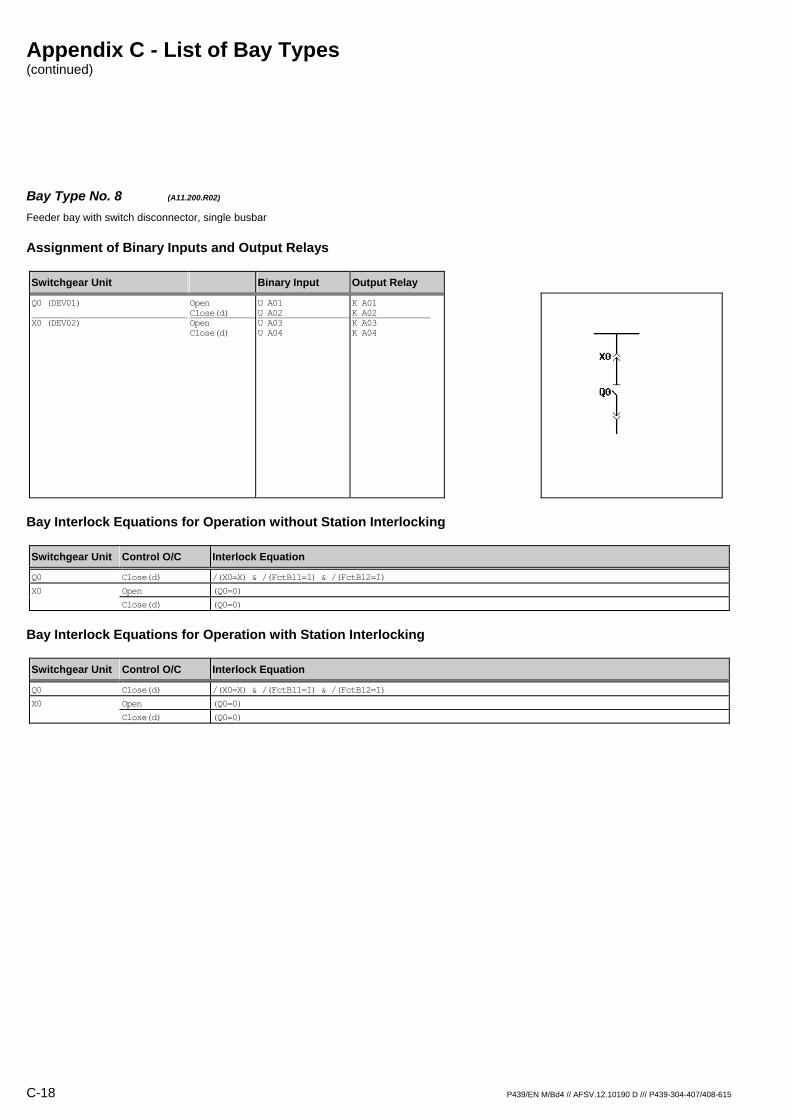
Bay Type No. 8 (A11.200.R02) Feeder bay with switch disconnector, single busbar
Assignment of Binary Inputs and Output Relays
Switchgear Unit Binary Input Output Relay
Q0 (DEV01) X0 (DEV02)
Open Close(d) Open Close(d)
U A01 U A02 U A03 U A04
K A01 K A02 K A03 K A04
Bay Interlock Equations for Operation without Station Interlocking
Switchgear Unit Control O/C Interlock Equation
Q0 Close(d) /(X0=X) & /(FctBl1=I) & /(FctBl2=I)
X0 Open (Q0=0)
Close(d) (Q0=0)
Bay Interlock Equations for Operation with Station Interlocking
Switchgear Unit Control O/C Interlock Equation
Q0 Close(d) /(X0=X) & /(FctBl1=I) & /(FctBl2=I)
X0 Open (Q0=0)
Close(d) (Q0=0)

Appendix C - List of Bay Types (continued)
P439/EN M/Bd4 // AFSV.12.10190 D /// P439-304-407/408-615 C-19
Bay Type No. 9 (A11.201.R01) Feeder bay with switch disconnector, single busbar
Assignment of Binary Inputs and Output Relays
Switchgear Unit Binary Input Output Relay
Q0 (DEV01) X0 (DEV02) Q8 (DEV03)
Open Close(d) Open Close(d) Open Close(d)
U A01 U A02 U A03 U A04 U A05 U A06
K A01 K A02 / / / /
Bay Interlock Equations for Operation without Station Interlocking
Switchgear Unit Control O/C Interlock Equation
Q0 Close(d) /(X0=X) & /(FctBl1=I) & /(FctBl2=I)
Bay Interlock Equations for Operation with Station Interlocking
Switchgear Unit Control O/C Interlock Equation
Q0 Close(d) /(X0=X) & /(FctBl1=I) & /(FctBl2=I)
Appendix C - List of Bay Types (continued)
C-20 P439/EN M/Bd4 // AFSV.12.10190 D /// P439-304-407/408-615
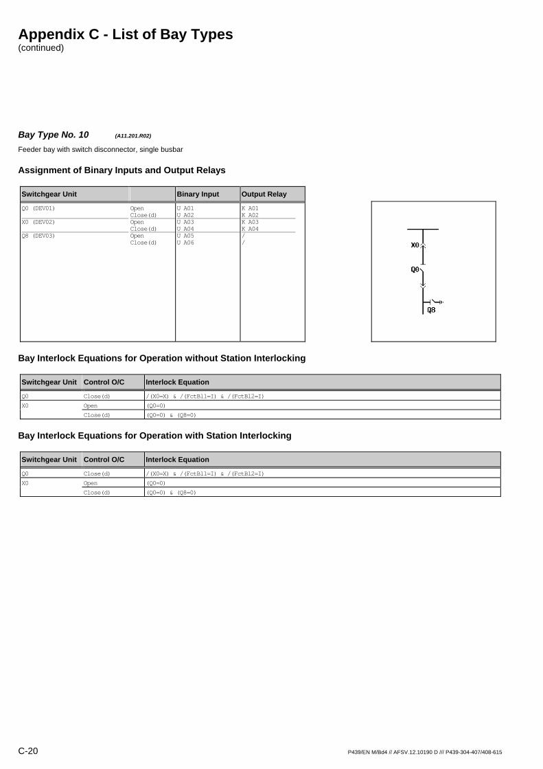
Bay Type No. 10 (A11.201.R02) Feeder bay with switch disconnector, single busbar
Assignment of Binary Inputs and Output Relays
Switchgear Unit Binary Input Output Relay
Q0 (DEV01) X0 (DEV02) Q8 (DEV03)
Open Close(d) Open Close(d) Open Close(d)
U A01 U A02 U A03 U A04 U A05 U A06
K A01 K A02 K A03 K A04 / /
Bay Interlock Equations for Operation without Station Interlocking
Switchgear Unit Control O/C Interlock Equation
Q0 Close(d) /(X0=X) & /(FctBl1=I) & /(FctBl2=I)
X0 Open (Q0=0)
Close(d) (Q0=0) & (Q8=0)
Bay Interlock Equations for Operation with Station Interlocking
Switchgear Unit Control O/C Interlock Equation
Q0 Close(d) /(X0=X) & /(FctBl1=I) & /(FctBl2=I)
X0 Open (Q0=0)
Close(d) (Q0=0) & (Q8=0)

Appendix C - List of Bay Types (continued)
P439/EN M/Bd4 // AFSV.12.10190 D /// P439-304-407/408-615 C-21
Bay Type No. 11 (A11.201.R03) Feeder bay with switch disconnector, single busbar
Assignment of Binary Inputs and Output Relays
Switchgear Unit Binary Input Output Relay
Q0 (DEV01) X0 (DEV02) Q8 (DEV03)
Open Close(d) Open Close(d) Open Close(d)
U A01 U A02 U A03 U A04 U A05 U A06
K A01 K A02 K A03 K A04 K A05 K A06
Bay Interlock Equations for Operation without Station Interlocking
Switchgear Unit Control O/C Interlock Equation
Q0 Close(d) /(X0=X) & /(FctBl1=I) & /(FctBl2=I)
Q8 Close(d) (X0=0)
X0 Open (Q0=0)
Close(d) (Q0=0) & (Q8=0)
Bay Interlock Equations for Operation with Station Interlocking
Switchgear Unit Control O/C Interlock Equation
Q0 Close(d) /(X0=X) & /(FctBl1=I) & /(FctBl2=I)
Q8 Close(d) (X0=0)
X0 Open (Q0=0)
Close(d) (Q0=0) & (Q8=0)

Appendix C - List of Bay Types (continued)
C-22 P439/EN M/Bd4 // AFSV.12.10190 D /// P439-304-407/408-615
Bay Type No. 12 (A11.400.R01) Feeder bay with switch disconnector / fuse unit, single busbar
Assignment of Binary Inputs and Output Relays
Switchgear Unit Binary Input Output Relay
Q0 (DEV01) X0 (DEV02) F (SIG_1: Signal S011)
Open Close(d) Open Close(d)
U A01 U A02 U A03 U A04 U B05
K A01 K A02 / / /
Bay Interlock Equations for Operation without Station Interlocking
Switchgear Unit Control O/C Interlock Equation
Q0 Close(d) /(X0=X) & /(FctBl1=I) & /(FctBl2=I)
Bay Interlock Equations for Operation with Station Interlocking
Switchgear Unit Control O/C Interlock Equation
Q0 Close(d) /(X0=X) & /(FctBl1=I) & /(FctBl2=I)
Appendix C - List of Bay Types (continued)
P439/EN M/Bd4 // AFSV.12.10190 D /// P439-304-407/408-615 C-23
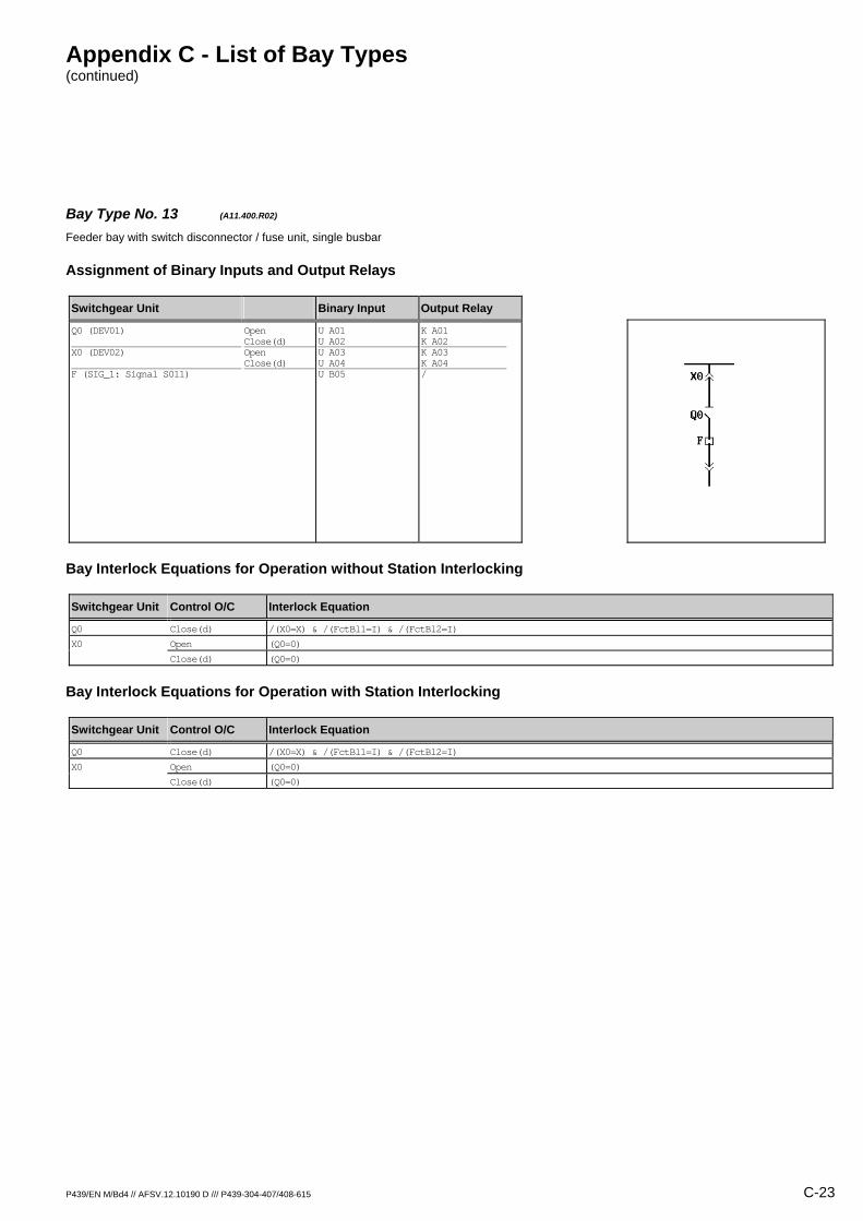
Bay Type No. 13 (A11.400.R02) Feeder bay with switch disconnector / fuse unit, single busbar
Assignment of Binary Inputs and Output Relays
Switchgear Unit Binary Input Output Relay
Q0 (DEV01) X0 (DEV02) F (SIG_1: Signal S011)
Open Close(d) Open Close(d)
U A01 U A02 U A03 U A04 U B05
K A01 K A02 K A03 K A04 /
Bay Interlock Equations for Operation without Station Interlocking
Switchgear Unit Control O/C Interlock Equation
Q0 Close(d) /(X0=X) & /(FctBl1=I) & /(FctBl2=I)
X0 Open (Q0=0)
Close(d) (Q0=0)
Bay Interlock Equations for Operation with Station Interlocking
Switchgear Unit Control O/C Interlock Equation
Q0 Close(d) /(X0=X) & /(FctBl1=I) & /(FctBl2=I)
X0 Open (Q0=0)
Close(d) (Q0=0)

Appendix C - List of Bay Types (continued)
C-24 P439/EN M/Bd4 // AFSV.12.10190 D /// P439-304-407/408-615
Bay Type No. 14 (A11.401.R01) Feeder bay with switch disconnector / fuse unit, single busbar
Assignment of Binary Inputs and Output Relays
Switchgear Unit Binary Input Output Relay
Q0 (DEV01) X0 (DEV02) Q8 (DEV03) F (SIG_1: Signal S011)
Open Close(d) Open Close(d) Open Close(d)
U A01 U A02 U A03 U A04 U A05 U A06 U B05
K A01 K A02 / / / / /
Bay Interlock Equations for Operation without Station Interlocking
Switchgear Unit Control O/C Interlock Equation
Q0 Close(d) /(X0=X) & /(FctBl1=I) & /(FctBl2=I)
Bay Interlock Equations for Operation with Station Interlocking
Switchgear Unit Control O/C Interlock Equation
Q0 Close(d) /(X0=X) & /(FctBl1=I) & /(FctBl2=I)
Appendix C - List of Bay Types (continued)
P439/EN M/Bd4 // AFSV.12.10190 D /// P439-304-407/408-615 C-25
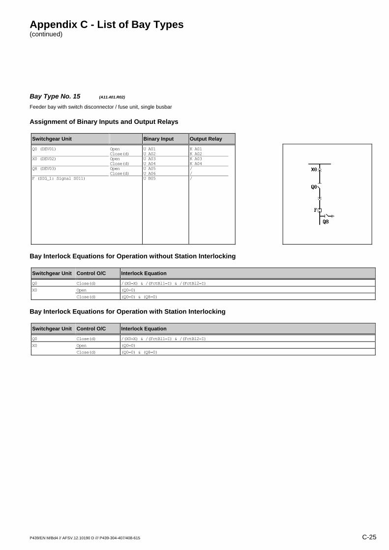
Bay Type No. 15 (A11.401.R02) Feeder bay with switch disconnector / fuse unit, single busbar
Assignment of Binary Inputs and Output Relays
Switchgear Unit Binary Input Output Relay
Q0 (DEV01) X0 (DEV02) Q8 (DEV03) F (SIG_1: Signal S011)
Open Close(d) Open Close(d) Open Close(d)
U A01 U A02 U A03 U A04 U A05 U A06 U B05
K A01 K A02 K A03 K A04 / / /
Bay Interlock Equations for Operation without Station Interlocking
Switchgear Unit Control O/C Interlock Equation
Q0 Close(d) /(X0=X) & /(FctBl1=I) & /(FctBl2=I)
X0 Open (Q0=0)
Close(d) (Q0=0) & (Q8=0)
Bay Interlock Equations for Operation with Station Interlocking
Switchgear Unit Control O/C Interlock Equation
Q0 Close(d) /(X0=X) & /(FctBl1=I) & /(FctBl2=I)
X0 Open (Q0=0)
Close(d) (Q0=0) & (Q8=0)

Appendix C - List of Bay Types (continued)
C-26 P439/EN M/Bd4 // AFSV.12.10190 D /// P439-304-407/408-615
Bay Type No. 16 (A11.401.R03) Feeder bay with switch disconnector / fuse unit, single busbar
Assignment of Binary Inputs and Output Relays
Switchgear Unit Binary Input Output Relay
Q0 (DEV01) X0 (DEV02) Q8 (DEV03) F (SIG_1: Signal S011)
Open Close(d) Open Close(d) Open Close(d)
U A01 U A02 U A03 U A04 U A05 U A06 U B05
K A01 K A02 K A03 K A04 K A05 K A06 /
Bay Interlock Equations for Operation without Station Interlocking
Switchgear Unit Control O/C Interlock Equation
Q0 Close(d) /(X0=X) & /(FctBl1=I) & /(FctBl2=I)
Q8 Close(d) (X0=0)
X0 Open (Q0=0)
Close(d) (Q0=0) & (Q8=0)
Bay Interlock Equations for Operation with Station Interlocking
Switchgear Unit Control O/C Interlock Equation
Q0 Close(d) /(X0=X) & /(FctBl1=I) & /(FctBl2=I)
Q8 Close(d) (X0=0)
X0 Open (Q0=0)
Close(d) (Q0=0) & (Q8=0)

Appendix C - List of Bay Types (continued)
P439/EN M/Bd4 // AFSV.12.10190 D /// P439-304-407/408-615 C-27
Bay Type No. 17 (A11.900.R01) Feeder bay with other switchgear unit, single busbar
Assignment of Binary Inputs and Output Relays
Switchgear Unit Binary Input Output Relay
X0 (DEV01)
Open Close(d)
U A01 U A02
K A01 K A02
Bay Interlock Equations for Operation without Station Interlocking
Switchgear Unit Control O/C Interlock Equation
Interlock Equations not defined
Bay Interlock Equations for Operation with Station Interlocking
Switchgear Unit Control O/C Interlock Equation
Interlock Equations not defined

Appendix C - List of Bay Types (continued)
C-28 P439/EN M/Bd4 // AFSV.12.10190 D /// P439-304-407/408-615
Bay Type No. 504 (A11.901.R00) Feeder bay with other switchgear unit, single busbar
Assignment of Binary Inputs and Output Relays
Switchgear Unit Binary Input Output Relay
X0 (DEV02) Q8 (DEV03)
Open Close(d) Open Close(d)
U A03 U A04 U A05 U A06
/ / / /
Bay Interlock Equations for Operation without Station Interlocking
Switchgear Unit Control O/C Interlock Equation
Interlock Equations not defined
Bay Interlock Equations for Operation with Station Interlocking
Switchgear Unit Control O/C Interlock Equation
Interlock Equations not defined
Appendix C - List of Bay Types (continued)
P439/EN M/Bd4 // AFSV.12.10190 D /// P439-304-407/408-615 C-29
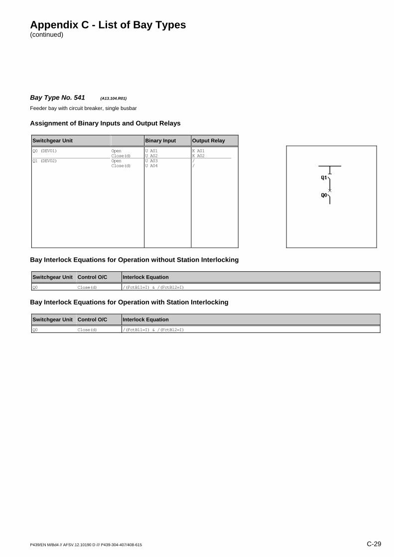
Bay Type No. 541 (A13.104.R01) Feeder bay with circuit breaker, single busbar
Assignment of Binary Inputs and Output Relays
Switchgear Unit Binary Input Output Relay
Q0 (DEV01) Q1 (DEV02)
Open Close(d) Open Close(d)
U A01 U A02 U A03 U A04
K A01 K A02 / /
Bay Interlock Equations for Operation without Station Interlocking
Switchgear Unit Control O/C Interlock Equation
Q0 Close(d) /(FctBl1=I) & /(FctBl2=I)
Bay Interlock Equations for Operation with Station Interlocking
Switchgear Unit Control O/C Interlock Equation
Q0 Close(d) /(FctBl1=I) & /(FctBl2=I)

Appendix C - List of Bay Types (continued)
C-30 P439/EN M/Bd4 // AFSV.12.10190 D /// P439-304-407/408-615
Bay Type No. 18 (A13.105.M03) Feeder bay with circuit breaker, single busbar, direct motor control
Assignment of Binary Inputs and Output Relays
Switchgear Unit Binary Input Output Relay
Q0 (DEV01) Q1 (DEV02) Q8 (DEV03) Mot.relay (SIG_1: Signal S012) Shunt wd. (CMD_1: Command C011) Mot.relay (CMD_1: Command C012)
Open Close(d) Open Close(d) Open Close(d)
U A01 U A02 U A03 U A04 U A05 U A06 U B06 / /
K A01 K A02 K A03 K A04 K A05 K A06 / K B05 K B06
Bay Interlock Equations for Operation without Station Interlocking
Switchgear Unit Control O/C Interlock Equation
Q0 Close(d) /(Q1=X) & (Q8=0) & /(FctBl1=I) & /(FctBl2=I)
Q1 Open (Q0=0)
Close(d) (Q0=0) & (Q8=0)
Q8 Close(d) (Q0=0) & (Q1=0)
Bay Interlock Equations for Operation with Station Interlocking
Switchgear Unit Control O/C Interlock Equation
Q0 Close(d) /(Q1=X) & (Q8=0) & /(FctBl1=I) & /(FctBl2=I)
Q1 Open (Q0=0)
Close(d) (Q0=0) & (Q8=0)
Q8 Close(d) (Q0=0) & (Q1=0)

Appendix C - List of Bay Types (continued)
P439/EN M/Bd4 // AFSV.12.10190 D /// P439-304-407/408-615 C-31
Bay Type No. 19 (A13.105.R01) Feeder bay with circuit breaker, single busbar
Assignment of Binary Inputs and Output Relays
Switchgear Unit Binary Input Output Relay
Q0 (DEV01) Q1 (DEV02) Q8 (DEV03)
Open Close(d) Open Close(d) Open Close(d)
U A01 U A02 U A03 U A04 U A05 U A06
K A01 K A02 / / / /
Bay Interlock Equations for Operation without Station Interlocking
Switchgear Unit Control O/C Interlock Equation
Q0 Close(d) /(Q1=X) & (Q8=0) & /(FctBl1=I) & /(FctBl2=I)
Bay Interlock Equations for Operation with Station Interlocking
Switchgear Unit Control O/C Interlock Equation
Q0 Close(d) /(Q1=X) & (Q8=0) & /(FctBl1=I) & /(FctBl2=I)

Appendix C - List of Bay Types (continued)
C-32 P439/EN M/Bd4 // AFSV.12.10190 D /// P439-304-407/408-615
Bay Type No. 20 (A13.105.R02) Feeder bay with circuit breaker, single busbar
Assignment of Binary Inputs and Output Relays
Switchgear Unit Binary Input Output Relay
Q0 (DEV01) Q1 (DEV02) Q8 (DEV03)
Open Close(d) Open Close(d) Open Close(d)
U A01 U A02 U A03 U A04 U A05 U A06
K A01 K A02 K A03 K A04 / /
Bay Interlock Equations for Operation without Station Interlocking
Switchgear Unit Control O/C Interlock Equation
Q0 Close(d) /(Q1=X) & (Q8=0) & /(FctBl1=I) & /(FctBl2=I)
Q1 Open (Q0=0)
Close(d) (Q0=0) & (Q8=0)
Bay Interlock Equations for Operation with Station Interlocking
Switchgear Unit Control O/C Interlock Equation
Q0 Close(d) /(Q1=X) & (Q8=0) & /(FctBl1=I) & /(FctBl2=I)
Q1 Open (Q0=0)
Close(d) (Q0=0) & (Q8=0)

Appendix C - List of Bay Types (continued)
P439/EN M/Bd4 // AFSV.12.10190 D /// P439-304-407/408-615 C-33
Bay Type No. 21 (A13.105.R03) Feeder bay with circuit breaker, single busbar
Assignment of Binary Inputs and Output Relays
Switchgear Unit Binary Input Output Relay
Q0 (DEV01) Q1 (DEV02) Q8 (DEV03)
Open Close(d) Open Close(d) Open Close(d)
U A01 U A02 U A03 U A04 U A05 U A06
K A01 K A02 K A03 K A04 K A05 K A06
Bay Interlock Equations for Operation without Station Interlocking
Switchgear Unit Control O/C Interlock Equation
Q0 Close(d) /(Q1=X) & (Q8=0) & /(FctBl1=I) & /(FctBl2=I)
Q1 Open (Q0=0)
Close(d) (Q0=0) & (Q8=0)
Q8 Close(d) (Q0=0) & (Q1=0)
Bay Interlock Equations for Operation with Station Interlocking
Switchgear Unit Control O/C Interlock Equation
Q0 Close(d) /(Q1=X) & (Q8=0) & /(FctBl1=I) & /(FctBl2=I)
Q1 Open (Q0=0)
Close(d) (Q0=0) & (Q8=0)
Q8 Close(d) (Q0=0) & (Q1=0)

Appendix C - List of Bay Types (continued)
C-34 P439/EN M/Bd4 // AFSV.12.10190 D /// P439-304-407/408-615
Bay Type No. 557 (A13.106.R03) Feeder bay with circuit breaker, single busbar
Assignment of Binary Inputs and Output Relays
Switchgear Unit Binary Input Output Relay
Q0 (DEV01) Q1 (DEV02) Q9 (DEV03)
Open Close(d) Open Close(d) Open Close(d)
U A01 U A02 U A03 U A04 U A05 U A06
K A01 K A02 K A03 K A04 K A05 K A06
Bay Interlock Equations for Operation without Station Interlocking
Switchgear Unit Control O/C Interlock Equation
Q0 Close(d) /(Q1=X) & /(Q9=X) & /(FctBl1=I) & /(FctBl2=I)
Q1 Open (Q0=0)
Close(d) (Q0=0)
Q9 Open (Q0=0)
Close(d) (Q0=0)
Bay Interlock Equations for Operation with Station Interlocking
Switchgear Unit Control O/C Interlock Equation
Q0 Close(d) /(Q1=X) & /(Q9=X) & /(FctBl1=I) & /(FctBl2=I)
Q1 Open (Q0=0)
Close(d) (Q0=0)
Q9 Open (Q0=0)
Close(d) (Q0=0)

Appendix C - List of Bay Types (continued)
P439/EN M/Bd4 // AFSV.12.10190 D /// P439-304-407/408-615 C-35
Bay Type No. 22 (A13.107.M04) Feeder bay with circuit breaker, single busbar, direct motor control
Assignment of Binary Inputs and Output Relays
Switchgear Unit Binary Input Output Relay
Q0 (DEV01) Q1 (DEV02) Q9 (DEV03) Q8 (DEV04) Mot.relay (SIG_1: Signal S012) Shunt wd. (CMD_1: Command C011) Mot.relay (CMD_1: Command C012)
Open Close(d) Open Close(d) Open Close(d) Open Close(d)
U A01 U A02 U A03 U A04 U A05 U A06 U B01 U B02 U B06 / /
K A01 K A02 K A03 K A04 K A05 K A06 K B01 K B02 / K B05 K B06
Bay Interlock Equations for Operation without Station Interlocking
Switchgear Unit Control O/C Interlock Equation
Q0 Close(d) /(Q1=X) & /(Q9=X) & /(FctBl1=I) & /(FctBl2=I)
Q1 Open (Q0=0)
Close(d) (Q0=0)
Q8 Close(d) (Q9=0)
Q9 Open (Q0=0)
Close(d) (Q0=0) & (Q8=0)
Bay Interlock Equations for Operation with Station Interlocking
Switchgear Unit Control O/C Interlock Equation
Q0 Close(d) /(Q1=X) & /(Q9=X) & /(FctBl1=I) & /(FctBl2=I)
Q1 Open (Q0=0)
Close(d) (Q0=0)
Q8 Close(d) (Q9=0)
Q9 Open (Q0=0)
Close(d) (Q0=0) & (Q8=0)
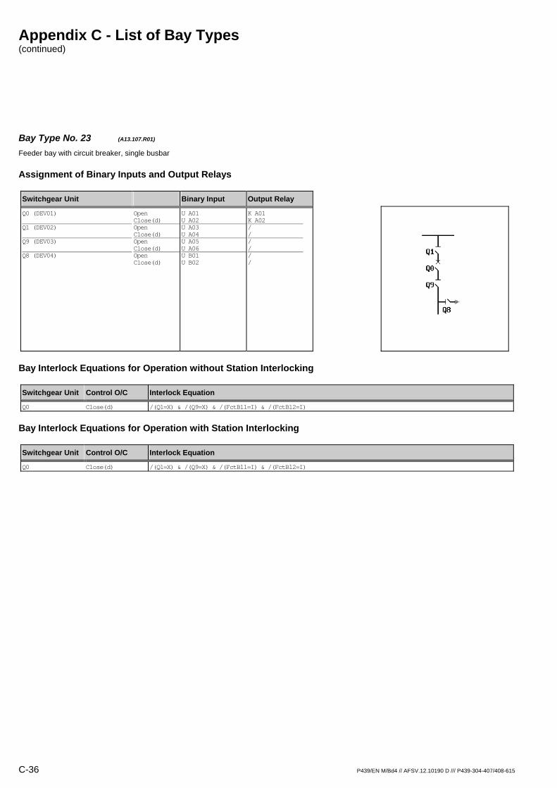
Appendix C - List of Bay Types (continued)
C-36 P439/EN M/Bd4 // AFSV.12.10190 D /// P439-304-407/408-615
Bay Type No. 23 (A13.107.R01) Feeder bay with circuit breaker, single busbar
Assignment of Binary Inputs and Output Relays
Switchgear Unit Binary Input Output Relay
Q0 (DEV01) Q1 (DEV02) Q9 (DEV03) Q8 (DEV04)
Open Close(d) Open Close(d) Open Close(d) Open Close(d)
U A01 U A02 U A03 U A04 U A05 U A06 U B01 U B02
K A01 K A02 / / / / / /
Bay Interlock Equations for Operation without Station Interlocking
Switchgear Unit Control O/C Interlock Equation
Q0 Close(d) /(Q1=X) & /(Q9=X) & /(FctBl1=I) & /(FctBl2=I)
Bay Interlock Equations for Operation with Station Interlocking
Switchgear Unit Control O/C Interlock Equation
Q0 Close(d) /(Q1=X) & /(Q9=X) & /(FctBl1=I) & /(FctBl2=I)
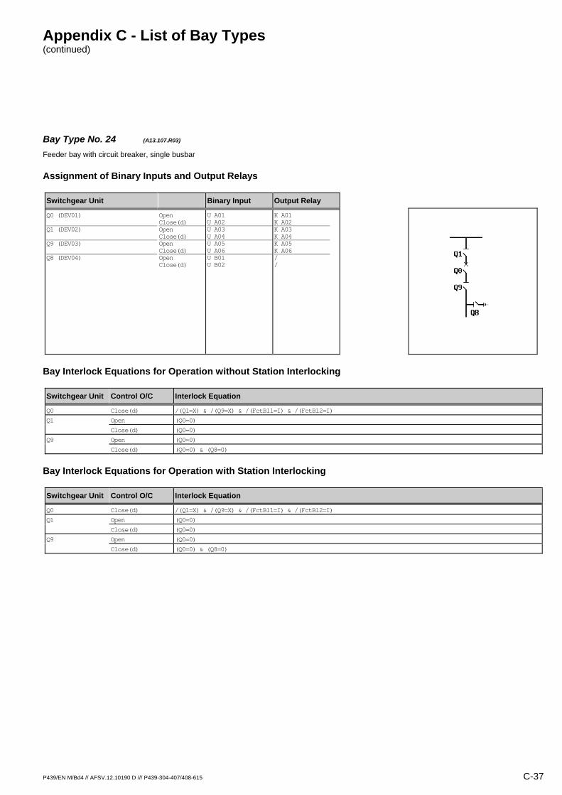
Appendix C - List of Bay Types (continued)
P439/EN M/Bd4 // AFSV.12.10190 D /// P439-304-407/408-615 C-37
Bay Type No. 24 (A13.107.R03) Feeder bay with circuit breaker, single busbar
Assignment of Binary Inputs and Output Relays
Switchgear Unit Binary Input Output Relay
Q0 (DEV01) Q1 (DEV02) Q9 (DEV03) Q8 (DEV04)
Open Close(d) Open Close(d) Open Close(d) Open Close(d)
U A01 U A02 U A03 U A04 U A05 U A06 U B01 U B02
K A01 K A02 K A03 K A04 K A05 K A06 / /
Bay Interlock Equations for Operation without Station Interlocking
Switchgear Unit Control O/C Interlock Equation
Q0 Close(d) /(Q1=X) & /(Q9=X) & /(FctBl1=I) & /(FctBl2=I)
Q1 Open (Q0=0)
Close(d) (Q0=0)
Q9 Open (Q0=0)
Close(d) (Q0=0) & (Q8=0)
Bay Interlock Equations for Operation with Station Interlocking
Switchgear Unit Control O/C Interlock Equation
Q0 Close(d) /(Q1=X) & /(Q9=X) & /(FctBl1=I) & /(FctBl2=I)
Q1 Open (Q0=0)
Close(d) (Q0=0)
Q9 Open (Q0=0)
Close(d) (Q0=0) & (Q8=0)
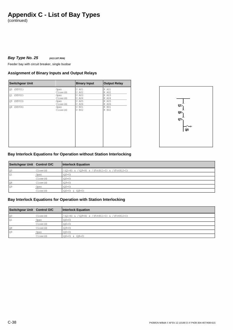
Appendix C - List of Bay Types (continued)
C-38 P439/EN M/Bd4 // AFSV.12.10190 D /// P439-304-407/408-615
Bay Type No. 25 (A13.107.R04) Feeder bay with circuit breaker, single busbar
Assignment of Binary Inputs and Output Relays
Switchgear Unit Binary Input Output Relay
Q0 (DEV01) Q1 (DEV02) Q9 (DEV03) Q8 (DEV04)
Open Close(d) Open Close(d) Open Close(d) Open Close(d)
U A01 U A02 U A03 U A04 U A05 U A06 U B01 U B02
K A01 K A02 K A03 K A04 K A05 K A06 K B01 K B02
Bay Interlock Equations for Operation without Station Interlocking
Switchgear Unit Control O/C Interlock Equation
Q0 Close(d) /(Q1=X) & /(Q9=X) & /(FctBl1=I) & /(FctBl2=I)
Q1 Open (Q0=0)
Close(d) (Q0=0)
Q8 Close(d) (Q9=0)
Q9 Open (Q0=0)
Close(d) (Q0=0) & (Q8=0)
Bay Interlock Equations for Operation with Station Interlocking
Switchgear Unit Control O/C Interlock Equation
Q0 Close(d) /(Q1=X) & /(Q9=X) & /(FctBl1=I) & /(FctBl2=I)
Q1 Open (Q0=0)
Close(d) (Q0=0)
Q8 Close(d) (Q9=0)
Q9 Open (Q0=0)
Close(d) (Q0=0) & (Q8=0)
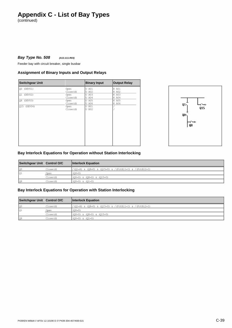
Appendix C - List of Bay Types (continued)
P439/EN M/Bd4 // AFSV.12.10190 D /// P439-304-407/408-615 C-39
Bay Type No. 508 (A13.111.R03) Feeder bay with circuit breaker, single busbar
Assignment of Binary Inputs and Output Relays
Switchgear Unit Binary Input Output Relay
Q0 (DEV01) Q1 (DEV02) Q8 (DEV03) Q15 (DEV04)
Open Close(d) Open Close(d) Open Close(d) Open Close(d)
U A01 U A02 U A03 U A04 U A05 U A06 U B01 U B02
K A01 K A02 K A03 K A04 K A05 K A06 / /
Bay Interlock Equations for Operation without Station Interlocking
Switchgear Unit Control O/C Interlock Equation
Q0 Close(d) /(Q1=X) & (Q8=0) & (Q15=0) & /(FctBl1=I) & /(FctBl2=I)
Q1 Open (Q0=0)
Close(d) (Q0=0) & (Q8=0) & (Q15=0)
Q8 Close(d) (Q0=0) & (Q1=0)
Bay Interlock Equations for Operation with Station Interlocking
Switchgear Unit Control O/C Interlock Equation
Q0 Close(d) /(Q1=X) & (Q8=0) & (Q15=0) & /(FctBl1=I) & /(FctBl2=I)
Q1 Open (Q0=0)
Close(d) (Q0=0) & (Q8=0) & (Q15=0)
Q8 Close(d) (Q0=0) & (Q1=0)
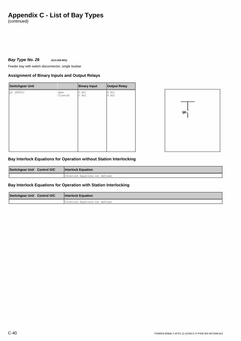
Appendix C - List of Bay Types (continued)
C-40 P439/EN M/Bd4 // AFSV.12.10190 D /// P439-304-407/408-615
Bay Type No. 26 (A13.200.R01) Feeder bay with switch disconnector, single busbar
Assignment of Binary Inputs and Output Relays
Switchgear Unit Binary Input Output Relay
Q0 (DEV01)
Open Close(d)
U A01 U A02
K A01 K A02
Bay Interlock Equations for Operation without Station Interlocking
Switchgear Unit Control O/C Interlock Equation
Interlock Equations not defined
Bay Interlock Equations for Operation with Station Interlocking
Switchgear Unit Control O/C Interlock Equation
Interlock Equations not defined
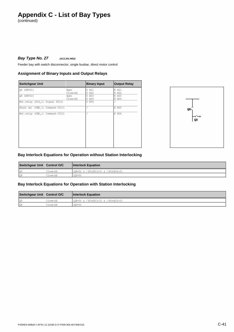
Appendix C - List of Bay Types (continued)
P439/EN M/Bd4 // AFSV.12.10190 D /// P439-304-407/408-615 C-41
Bay Type No. 27 (A13.201.M02) Feeder bay with switch disconnector, single busbar, direct motor control
Assignment of Binary Inputs and Output Relays
Switchgear Unit Binary Input Output Relay
Q0 (DEV01) Q8 (DEV02) Mot.relay (SIG_1: Signal S012) Shunt wd. (CMD_1: Command C011) Mot.relay (CMD_1: Command C012)
Open Close(d) Open Close(d)
U A01 U A02 U A03 U A04 U B06 / /
K A01 K A02 K A03 K A04 / K B05 K B06
Bay Interlock Equations for Operation without Station Interlocking
Switchgear Unit Control O/C Interlock Equation
Q0 Close(d) (Q8=0) & /(FctBl1=I) & /(FctBl2=I)
Q8 Close(d) (Q0=0)
Bay Interlock Equations for Operation with Station Interlocking
Switchgear Unit Control O/C Interlock Equation
Q0 Close(d) (Q8=0) & /(FctBl1=I) & /(FctBl2=I)
Q8 Close(d) (Q0=0)

Appendix C - List of Bay Types (continued)
C-42 P439/EN M/Bd4 // AFSV.12.10190 D /// P439-304-407/408-615
Bay Type No. 28 (A13.201.R01) Feeder bay with switch disconnector, single busbar
Assignment of Binary Inputs and Output Relays
Switchgear Unit Binary Input Output Relay
Q0 (DEV01) Q8 (DEV02)
Open Close(d) Open Close(d)
U A01 U A02 U A03 U A04
K A01 K A02 / /
Bay Interlock Equations for Operation without Station Interlocking
Switchgear Unit Control O/C Interlock Equation
Q0 Close(d) (Q8=0) & /(FctBl1=I) & /(FctBl2=I)
Bay Interlock Equations for Operation with Station Interlocking
Switchgear Unit Control O/C Interlock Equation
Q0 Close(d) (Q8=0) & /(FctBl1=I) & /(FctBl2=I)
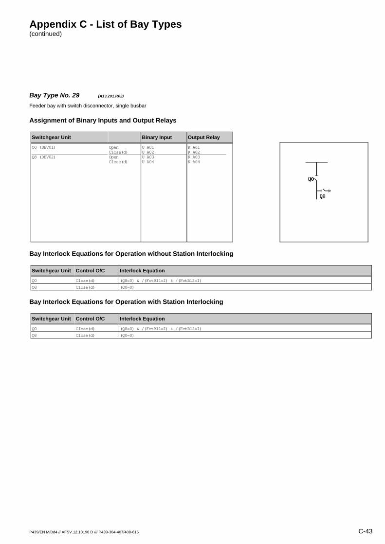
Appendix C - List of Bay Types (continued)
P439/EN M/Bd4 // AFSV.12.10190 D /// P439-304-407/408-615 C-43
Bay Type No. 29 (A13.201.R02) Feeder bay with switch disconnector, single busbar
Assignment of Binary Inputs and Output Relays
Switchgear Unit Binary Input Output Relay
Q0 (DEV01) Q8 (DEV02)
Open Close(d) Open Close(d)
U A01 U A02 U A03 U A04
K A01 K A02 K A03 K A04
Bay Interlock Equations for Operation without Station Interlocking
Switchgear Unit Control O/C Interlock Equation
Q0 Close(d) (Q8=0) & /(FctBl1=I) & /(FctBl2=I)
Q8 Close(d) (Q0=0)
Bay Interlock Equations for Operation with Station Interlocking
Switchgear Unit Control O/C Interlock Equation
Q0 Close(d) (Q8=0) & /(FctBl1=I) & /(FctBl2=I)
Q8 Close(d) (Q0=0)

Appendix C - List of Bay Types (continued)
C-44 P439/EN M/Bd4 // AFSV.12.10190 D /// P439-304-407/408-615
Bay Type No. 30 (A13.205.M03) Feeder bay with switch disconnector, single busbar, direct motor control
Assignment of Binary Inputs and Output Relays
Switchgear Unit Binary Input Output Relay
Q0 (DEV01) Q1 (DEV02) Q8 (DEV03) Mot.relay (SIG_1: Signal S012) Shunt wd. (CMD_1: Command C011) Mot.relay (CMD_1: Command C012)
Open Close(d) Open Close(d) Open Close(d)
U A01 U A02 U A03 U A04 U A05 U A06 U B06 / /
K A01 K A02 K A03 K A04 K A05 K A06 / K B05 K B06
Bay Interlock Equations for Operation without Station Interlocking
Switchgear Unit Control O/C Interlock Equation
Q0 Close(d) /(Q1=X) & (Q8=0) & /(FctBl1=I) & /(FctBl2=I)
Q1 Open (Q0=0)
Close(d) (Q0=0) & (Q8=0)
Q8 Close(d) (Q0=0) & (Q1=0)
Bay Interlock Equations for Operation with Station Interlocking
Switchgear Unit Control O/C Interlock Equation
Q0 Close(d) /(Q1=X) & (Q8=0) & /(FctBl1=I) & /(FctBl2=I)
Q1 Open (Q0=0)
Close(d) (Q0=0) & (Q8=0)
Q8 Close(d) (Q0=0) & (Q1=0)

Appendix C - List of Bay Types (continued)
P439/EN M/Bd4 // AFSV.12.10190 D /// P439-304-407/408-615 C-45
Bay Type No. 31 (A13.205.R01) Feeder bay with switch disconnector, single busbar
Assignment of Binary Inputs and Output Relays
Switchgear Unit Binary Input Output Relay
Q0 (DEV01) Q1 (DEV02) Q8 (DEV03)
Open Close(d) Open Close(d) Open Close(d)
U A01 U A02 U A03 U A04 U A05 U A06
K A01 K A02 / / / /
Bay Interlock Equations for Operation without Station Interlocking
Switchgear Unit Control O/C Interlock Equation
Q0 Close(d) /(Q1=X) & (Q8=0) & /(FctBl1=I) & /(FctBl2=I)
Bay Interlock Equations for Operation with Station Interlocking
Switchgear Unit Control O/C Interlock Equation
Q0 Close(d) /(Q1=X) & (Q8=0) & /(FctBl1=I) & /(FctBl2=I)

Appendix C - List of Bay Types (continued)
C-46 P439/EN M/Bd4 // AFSV.12.10190 D /// P439-304-407/408-615
Bay Type No. 32 (A13.205.R02) Feeder bay with switch disconnector, single busbar
Assignment of Binary Inputs and Output Relays
Switchgear Unit Binary Input Output Relay
Q0 (DEV01) Q1 (DEV02) Q8 (DEV03)
Open Close(d) Open Close(d) Open Close(d)
U A01 U A02 U A03 U A04 U A05 U A06
K A01 K A02 K A03 K A04 / /
Bay Interlock Equations for Operation without Station Interlocking
Switchgear Unit Control O/C Interlock Equation
Q0 Close(d) /(Q1=X) & (Q8=0) & /(FctBl1=I) & /(FctBl2=I)
Q1 Open (Q0=0)
Close(d) (Q0=0) & (Q8=0)
Bay Interlock Equations for Operation with Station Interlocking
Switchgear Unit Control O/C Interlock Equation
Q0 Close(d) /(Q1=X) & (Q8=0) & /(FctBl1=I) & /(FctBl2=I)
Q1 Open (Q0=0)
Close(d) (Q0=0) & (Q8=0)

Appendix C - List of Bay Types (continued)
P439/EN M/Bd4 // AFSV.12.10190 D /// P439-304-407/408-615 C-47
Bay Type No. 33 (A13.205.R03) Feeder bay with switch disconnector, single busbar
Assignment of Binary Inputs and Output Relays
Switchgear Unit Binary Input Output Relay
Q0 (DEV01) Q1 (DEV02) Q8 (DEV03)
Open Close(d) Open Close(d) Open Close(d)
U A01 U A02 U A03 U A04 U A05 U A06
K A01 K A02 K A03 K A04 K A05 K A06
Bay Interlock Equations for Operation without Station Interlocking
Switchgear Unit Control O/C Interlock Equation
Q0 Close(d) /(Q1=X) & (Q8=0) & /(FctBl1=I) & /(FctBl2=I)
Q1 Open (Q0=0)
Close(d) (Q0=0) & (Q8=0)
Q8 Close(d) (Q0=0) & (Q1=0)
Bay Interlock Equations for Operation with Station Interlocking
Switchgear Unit Control O/C Interlock Equation
Q0 Close(d) /(Q1=X) & (Q8=0) & /(FctBl1=I) & /(FctBl2=I)
Q1 Open (Q0=0)
Close(d) (Q0=0) & (Q8=0)
Q8 Close(d) (Q0=0) & (Q1=0)

Appendix C - List of Bay Types (continued)
C-48 P439/EN M/Bd4 // AFSV.12.10190 D /// P439-304-407/408-615
Bay Type No. 34 (A13.400.R01) Feeder bay with switch disconnector / fuse unit, single busbar
Assignment of Binary Inputs and Output Relays
Switchgear Unit Binary Input Output Relay
Q0 (DEV01) F (SIG_1: Signal S011)
Open Close(d)
U A01 U A02 U B05
K A01 K A02 /
Bay Interlock Equations for Operation without Station Interlocking
Switchgear Unit Control O/C Interlock Equation
Interlock Equations not defined
Bay Interlock Equations for Operation with Station Interlocking
Switchgear Unit Control O/C Interlock Equation
Interlock Equations not defined

Appendix C - List of Bay Types (continued)
P439/EN M/Bd4 // AFSV.12.10190 D /// P439-304-407/408-615 C-49
Bay Type No. 35 (A13.401.M02) Feeder bay with switch disconnector / fuse unit, single busbar, direct motor control
Assignment of Binary Inputs and Output Relays
Switchgear Unit Binary Input Output Relay
Q0 (DEV01) Q8 (DEV02) F (SIG_1: Signal S011) Mot.relay (SIG_1: Signal S012) Shunt wd. (CMD_1: Command C011) Mot.relay (CMD_1: Command C012)
Open Close(d) Open Close(d)
U A01 U A02 U A03 U A04 U B05 U B06 / /
K A01 K A02 K A03 K A04 / / K B05 K B06
Bay Interlock Equations for Operation without Station Interlocking
Switchgear Unit Control O/C Interlock Equation
Q0 Close(d) (Q8=0) & /(FctBl1=I) & /(FctBl2=I)
Q8 Close(d) (Q0=0)
Bay Interlock Equations for Operation with Station Interlocking
Switchgear Unit Control O/C Interlock Equation
Q0 Close(d) (Q8=0) & /(FctBl1=I) & /(FctBl2=I)
Q8 Close(d) (Q0=0)

Appendix C - List of Bay Types (continued)
C-50 P439/EN M/Bd4 // AFSV.12.10190 D /// P439-304-407/408-615
Bay Type No. 36 (A13.401.R01) Feeder bay with switch disconnector / fuse unit, single busbar
Assignment of Binary Inputs and Output Relays
Switchgear Unit Binary Input Output Relay
Q0 (DEV01) Q8 (DEV02) F (SIG_1: Signal S011)
Open Close(d) Open Close(d)
U A01 U A02 U A03 U A04 U B05
K A01 K A02 / / /
Bay Interlock Equations for Operation without Station Interlocking
Switchgear Unit Control O/C Interlock Equation
Q0 Close(d) (Q8=0) & /(FctBl1=I) & /(FctBl2=I)
Bay Interlock Equations for Operation with Station Interlocking
Switchgear Unit Control O/C Interlock Equation
Q0 Close(d) (Q8=0) & /(FctBl1=I) & /(FctBl2=I)

Appendix C - List of Bay Types (continued)
P439/EN M/Bd4 // AFSV.12.10190 D /// P439-304-407/408-615 C-51
Bay Type No. 37 (A13.401.R02) Feeder bay with switch disconnector / fuse unit, single busbar
Assignment of Binary Inputs and Output Relays
Switchgear Unit Binary Input Output Relay
Q0 (DEV01) Q8 (DEV02) F (SIG_1: Signal S011)
Open Close(d) Open Close(d)
U A01 U A02 U A03 U A04 U B05
K A01 K A02 K A03 K A04 /
Bay Interlock Equations for Operation without Station Interlocking
Switchgear Unit Control O/C Interlock Equation
Q0 Close(d) (Q8=0) & /(FctBl1=I) & /(FctBl2=I)
Q8 Close(d) (Q0=0)
Bay Interlock Equations for Operation with Station Interlocking
Switchgear Unit Control O/C Interlock Equation
Q0 Close(d) (Q8=0) & /(FctBl1=I) & /(FctBl2=I)
Q8 Close(d) (Q0=0)
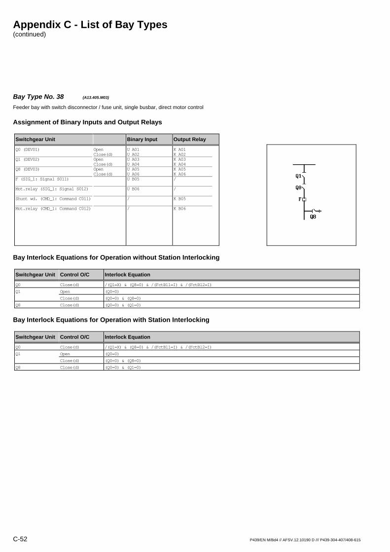
Appendix C - List of Bay Types (continued)
C-52 P439/EN M/Bd4 // AFSV.12.10190 D /// P439-304-407/408-615
Bay Type No. 38 (A13.405.M03) Feeder bay with switch disconnector / fuse unit, single busbar, direct motor control
Assignment of Binary Inputs and Output Relays
Switchgear Unit Binary Input Output Relay
Q0 (DEV01) Q1 (DEV02) Q8 (DEV03) F (SIG_1: Signal S011) Mot.relay (SIG_1: Signal S012) Shunt wd. (CMD_1: Command C011) Mot.relay (CMD_1: Command C012)
Open Close(d) Open Close(d) Open Close(d)
U A01 U A02 U A03 U A04 U A05 U A06 U B05 U B06 / /
K A01 K A02 K A03 K A04 K A05 K A06 / / K B05 K B06
Bay Interlock Equations for Operation without Station Interlocking
Switchgear Unit Control O/C Interlock Equation
Q0 Close(d) /(Q1=X) & (Q8=0) & /(FctBl1=I) & /(FctBl2=I)
Q1 Open (Q0=0)
Close(d) (Q0=0) & (Q8=0)
Q8 Close(d) (Q0=0) & (Q1=0)
Bay Interlock Equations for Operation with Station Interlocking
Switchgear Unit Control O/C Interlock Equation
Q0 Close(d) /(Q1=X) & (Q8=0) & /(FctBl1=I) & /(FctBl2=I)
Q1 Open (Q0=0)
Close(d) (Q0=0) & (Q8=0)
Q8 Close(d) (Q0=0) & (Q1=0)
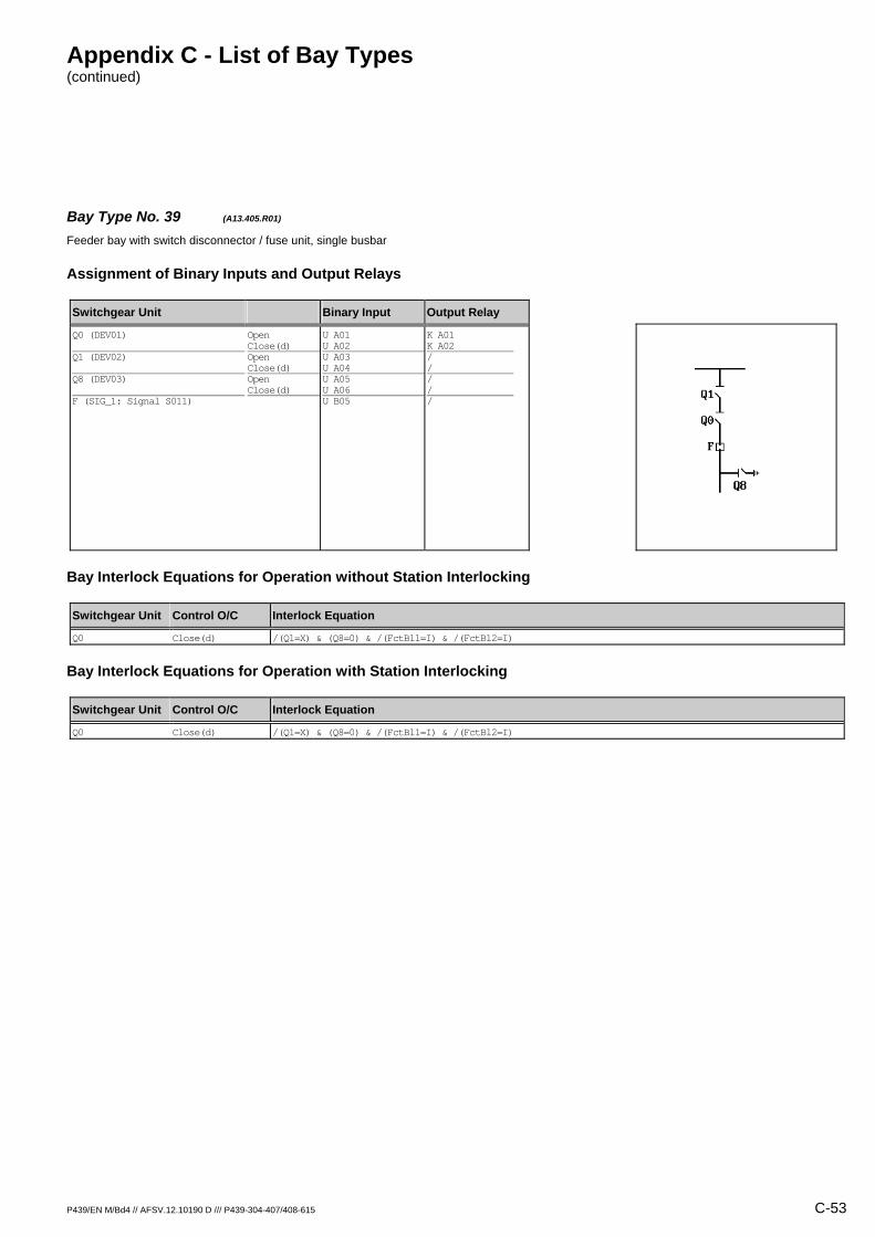
Appendix C - List of Bay Types (continued)
P439/EN M/Bd4 // AFSV.12.10190 D /// P439-304-407/408-615 C-53
Bay Type No. 39 (A13.405.R01) Feeder bay with switch disconnector / fuse unit, single busbar
Assignment of Binary Inputs and Output Relays
Switchgear Unit Binary Input Output Relay
Q0 (DEV01) Q1 (DEV02) Q8 (DEV03) F (SIG_1: Signal S011)
Open Close(d) Open Close(d) Open Close(d)
U A01 U A02 U A03 U A04 U A05 U A06 U B05
K A01 K A02 / / / / /
Bay Interlock Equations for Operation without Station Interlocking
Switchgear Unit Control O/C Interlock Equation
Q0 Close(d) /(Q1=X) & (Q8=0) & /(FctBl1=I) & /(FctBl2=I)
Bay Interlock Equations for Operation with Station Interlocking
Switchgear Unit Control O/C Interlock Equation
Q0 Close(d) /(Q1=X) & (Q8=0) & /(FctBl1=I) & /(FctBl2=I)
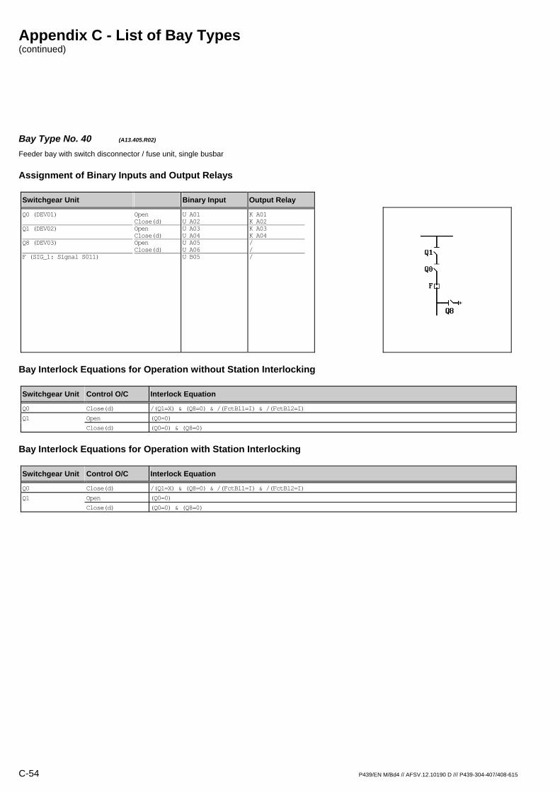
Appendix C - List of Bay Types (continued)
C-54 P439/EN M/Bd4 // AFSV.12.10190 D /// P439-304-407/408-615
Bay Type No. 40 (A13.405.R02) Feeder bay with switch disconnector / fuse unit, single busbar
Assignment of Binary Inputs and Output Relays
Switchgear Unit Binary Input Output Relay
Q0 (DEV01) Q1 (DEV02) Q8 (DEV03) F (SIG_1: Signal S011)
Open Close(d) Open Close(d) Open Close(d)
U A01 U A02 U A03 U A04 U A05 U A06 U B05
K A01 K A02 K A03 K A04 / / /
Bay Interlock Equations for Operation without Station Interlocking
Switchgear Unit Control O/C Interlock Equation
Q0 Close(d) /(Q1=X) & (Q8=0) & /(FctBl1=I) & /(FctBl2=I)
Q1 Open (Q0=0)
Close(d) (Q0=0) & (Q8=0)
Bay Interlock Equations for Operation with Station Interlocking
Switchgear Unit Control O/C Interlock Equation
Q0 Close(d) /(Q1=X) & (Q8=0) & /(FctBl1=I) & /(FctBl2=I)
Q1 Open (Q0=0)
Close(d) (Q0=0) & (Q8=0)
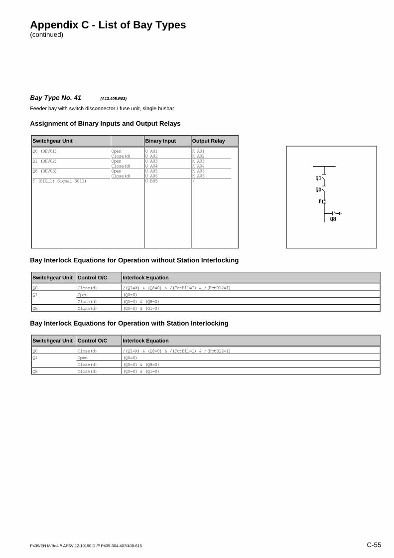
Appendix C - List of Bay Types (continued)
P439/EN M/Bd4 // AFSV.12.10190 D /// P439-304-407/408-615 C-55
Bay Type No. 41 (A13.405.R03) Feeder bay with switch disconnector / fuse unit, single busbar
Assignment of Binary Inputs and Output Relays
Switchgear Unit Binary Input Output Relay
Q0 (DEV01) Q1 (DEV02) Q8 (DEV03) F (SIG_1: Signal S011)
Open Close(d) Open Close(d) Open Close(d)
U A01 U A02 U A03 U A04 U A05 U A06 U B05
K A01 K A02 K A03 K A04 K A05 K A06 /
Bay Interlock Equations for Operation without Station Interlocking
Switchgear Unit Control O/C Interlock Equation
Q0 Close(d) /(Q1=X) & (Q8=0) & /(FctBl1=I) & /(FctBl2=I)
Q1 Open (Q0=0)
Close(d) (Q0=0) & (Q8=0)
Q8 Close(d) (Q0=0) & (Q1=0)
Bay Interlock Equations for Operation with Station Interlocking
Switchgear Unit Control O/C Interlock Equation
Q0 Close(d) /(Q1=X) & (Q8=0) & /(FctBl1=I) & /(FctBl2=I)
Q1 Open (Q0=0)
Close(d) (Q0=0) & (Q8=0)
Q8 Close(d) (Q0=0) & (Q1=0)

Appendix C - List of Bay Types (continued)
C-56 P439/EN M/Bd4 // AFSV.12.10190 D /// P439-304-407/408-615
Bay Type No. 503 (A13.432.R02) Feeder bay with switch disconnector / fuse unit, single busbar
Assignment of Binary Inputs and Output Relays
Switchgear Unit Binary Input Output Relay
Q0 (DEV01) Q8 (DEV02) F (SIG_1: Signal S011)
Open Close(d) Open Close(d)
U A01 U A02 U A03 U A04 U B05
K A01 K A02 K A03 K A04 /
Bay Interlock Equations for Operation without Station Interlocking
Switchgear Unit Control O/C Interlock Equation
Q0 Close(d) (Q8=0) & /(FctBl1=I) & /(FctBl2=I)
Q8 Close(d) (Q0=0)
Bay Interlock Equations for Operation with Station Interlocking
Switchgear Unit Control O/C Interlock Equation
Q0 Close(d) (Q8=0) & /(FctBl1=I) & /(FctBl2=I)
Q8 Close(d) (Q0=0)

Appendix C - List of Bay Types (continued)
P439/EN M/Bd4 // AFSV.12.10190 D /// P439-304-407/408-615 C-57
Bay Type No. 507 (A13.433.R02) Feeder bay with switch disconnector / fuse unit, single busbar
Assignment of Binary Inputs and Output Relays
Switchgear Unit Binary Input Output Relay
Q0 (DEV01) Q8 (DEV02) Q15 (DEV03) F (SIG_1: Signal S011)
Open Close(d) Open Close(d) Open Close(d)
U A01 U A02 U A03 U A04 U A05 U A06 U B05
K A01 K A02 K A03 K A04 / / /
Bay Interlock Equations for Operation without Station Interlocking
Switchgear Unit Control O/C Interlock Equation
Q0 Close(d) (Q8=0) & (Q15=0) & /(FctBl1=I) & /(FctBl2=I)
Q8 Close(d) (Q0=0)
Bay Interlock Equations for Operation with Station Interlocking
Switchgear Unit Control O/C Interlock Equation
Q0 Close(d) (Q8=0) & (Q15=0) & /(FctBl1=I) & /(FctBl2=I)
Q8 Close(d) (Q0=0)
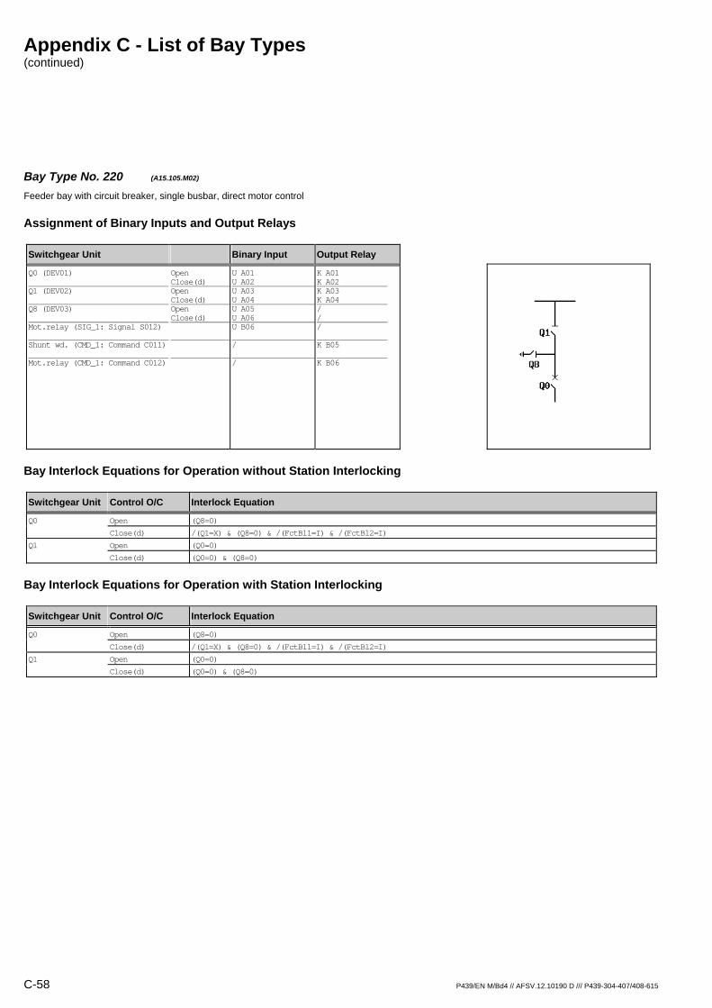
Appendix C - List of Bay Types (continued)
C-58 P439/EN M/Bd4 // AFSV.12.10190 D /// P439-304-407/408-615
Bay Type No. 220 (A15.105.M02) Feeder bay with circuit breaker, single busbar, direct motor control
Assignment of Binary Inputs and Output Relays
Switchgear Unit Binary Input Output Relay
Q0 (DEV01) Q1 (DEV02) Q8 (DEV03) Mot.relay (SIG_1: Signal S012) Shunt wd. (CMD_1: Command C011) Mot.relay (CMD_1: Command C012)
Open Close(d) Open Close(d) Open Close(d)
U A01 U A02 U A03 U A04 U A05 U A06 U B06 / /
K A01 K A02 K A03 K A04 / / / K B05 K B06
Bay Interlock Equations for Operation without Station Interlocking
Switchgear Unit Control O/C Interlock Equation
Q0 Open (Q8=0)
Close(d) /(Q1=X) & (Q8=0) & /(FctBl1=I) & /(FctBl2=I)
Q1 Open (Q0=0)
Close(d) (Q0=0) & (Q8=0)
Bay Interlock Equations for Operation with Station Interlocking
Switchgear Unit Control O/C Interlock Equation
Q0 Open (Q8=0)
Close(d) /(Q1=X) & (Q8=0) & /(FctBl1=I) & /(FctBl2=I)
Q1 Open (Q0=0)
Close(d) (Q0=0) & (Q8=0)
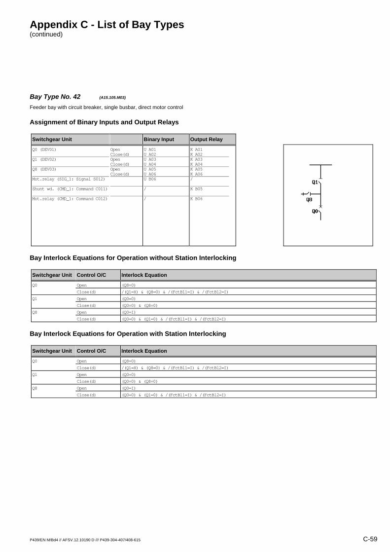
Appendix C - List of Bay Types (continued)
P439/EN M/Bd4 // AFSV.12.10190 D /// P439-304-407/408-615 C-59
Bay Type No. 42 (A15.105.M03) Feeder bay with circuit breaker, single busbar, direct motor control
Assignment of Binary Inputs and Output Relays
Switchgear Unit Binary Input Output Relay
Q0 (DEV01) Q1 (DEV02) Q8 (DEV03) Mot.relay (SIG_1: Signal S012) Shunt wd. (CMD_1: Command C011) Mot.relay (CMD_1: Command C012)
Open Close(d) Open Close(d) Open Close(d)
U A01 U A02 U A03 U A04 U A05 U A06 U B06 / /
K A01 K A02 K A03 K A04 K A05 K A06 / K B05 K B06
Bay Interlock Equations for Operation without Station Interlocking
Switchgear Unit Control O/C Interlock Equation
Q0 Open (Q8=0)
Close(d) /(Q1=X) & (Q8=0) & /(FctBl1=I) & /(FctBl2=I)
Q1 Open (Q0=0)
Close(d) (Q0=0) & (Q8=0)
Q8 Open (Q0=I)
Close(d) (Q0=0) & (Q1=0) & /(FctBl1=I) & /(FctBl2=I)
Bay Interlock Equations for Operation with Station Interlocking
Switchgear Unit Control O/C Interlock Equation
Q0 Open (Q8=0)
Close(d) /(Q1=X) & (Q8=0) & /(FctBl1=I) & /(FctBl2=I)
Q1 Open (Q0=0)
Close(d) (Q0=0) & (Q8=0)
Q8 Open (Q0=I)
Close(d) (Q0=0) & (Q1=0) & /(FctBl1=I) & /(FctBl2=I)

Appendix C - List of Bay Types (continued)
C-60 P439/EN M/Bd4 // AFSV.12.10190 D /// P439-304-407/408-615
Bay Type No. 43 (A15.105.R01) Feeder bay with circuit breaker, single busbar
Assignment of Binary Inputs and Output Relays
Switchgear Unit Binary Input Output Relay
Q0 (DEV01) Q1 (DEV02) Q8 (DEV03)
Open Close(d) Open Close(d) Open Close(d)
U A01 U A02 U A03 U A04 U A05 U A06
K A01 K A02 / / / /
Bay Interlock Equations for Operation without Station Interlocking
Switchgear Unit Control O/C Interlock Equation
Q0 Open (Q8=0)
Close(d) /(Q1=X) & (Q8=0) & /(FctBl1=I) & /(FctBl2=I)
Bay Interlock Equations for Operation with Station Interlocking
Switchgear Unit Control O/C Interlock Equation
Q0 Open (Q8=0)
Close(d) /(Q1=X) & (Q8=0) & /(FctBl1=I) & /(FctBl2=I)

Appendix C - List of Bay Types (continued)
P439/EN M/Bd4 // AFSV.12.10190 D /// P439-304-407/408-615 C-61
Bay Type No. 221 (A15.105.R02) Feeder bay with circuit breaker, single busbar
Assignment of Binary Inputs and Output Relays
Switchgear Unit Binary Input Output Relay
Q0 (DEV01) Q1 (DEV02) Q8 (DEV03)
Open Close(d) Open Close(d) Open Close(d)
U A01 U A02 U A03 U A04 U A05 U A06
K A01 K A02 K A03 K A04 / /
Bay Interlock Equations for Operation without Station Interlocking
Switchgear Unit Control O/C Interlock Equation
Q0 Open (Q8=0)
Close(d) /(Q1=X) & (Q8=0) & /(FctBl1=I) & /(FctBl2=I)
Q1 Open (Q0=0)
Close(d) (Q0=0) & (Q8=0)
Bay Interlock Equations for Operation with Station Interlocking
Switchgear Unit Control O/C Interlock Equation
Q0 Open (Q8=0)
Close(d) /(Q1=X) & (Q8=0) & /(FctBl1=I) & /(FctBl2=I)
Q1 Open (Q0=0)
Close(d) (Q0=0)

Appendix C - List of Bay Types (continued)
C-62 P439/EN M/Bd4 // AFSV.12.10190 D /// P439-304-407/408-615
Bay Type No. 44 (A15.105.R03) Feeder bay with circuit breaker, single busbar
Assignment of Binary Inputs and Output Relays
Switchgear Unit Binary Input Output Relay
Q0 (DEV01) Q1 (DEV02) Q8 (DEV03)
Open Close(d) Open Close(d) Open Close(d)
U A01 U A02 U A03 U A04 U A05 U A06
K A01 K A02 K A03 K A04 K A05 K A06
Bay Interlock Equations for Operation without Station Interlocking
Switchgear Unit Control O/C Interlock Equation
Q0 Open (Q8=0)
Close(d) /(Q1=X) & (Q8=0) & /(FctBl1=I) & /(FctBl2=I)
Q1 Open (Q0=0)
Close(d) (Q0=0) & (Q8=0)
Q8 Open (Q0=I)
Close(d) (Q0=0) & (Q1=0) & /(FctBl1=I) & /(FctBl2=I)
Bay Interlock Equations for Operation with Station Interlocking
Switchgear Unit Control O/C Interlock Equation
Q0 Open (Q8=0)
Close(d) /(Q1=X) & (Q8=0) & /(FctBl1=I) & /(FctBl2=I)
Q1 Open (Q0=0)
Close(d) (Q0=0)
Q8 Open (Q0=I)
Close(d) (Q0=0) & (Q1=0) & /(FctBl1=I) & /(FctBl2=I)
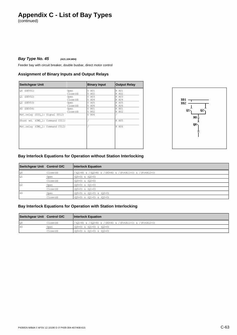
Appendix C - List of Bay Types (continued)
P439/EN M/Bd4 // AFSV.12.10190 D /// P439-304-407/408-615 C-63
Bay Type No. 45 (A21.104.M04) Feeder bay with circuit breaker, double busbar, direct motor control
Assignment of Binary Inputs and Output Relays
Switchgear Unit Binary Input Output Relay
Q0 (DEV01) Q1 (DEV02) Q2 (DEV03) X0 (DEV04) Mot.relay (SIG_1: Signal S012) Shunt wd. (CMD_1: Command C011) Mot.relay (CMD_1: Command C012)
Open Close(d) Open Close(d) Open Close(d) Open Close(d)
U A01 U A02 U A03 U A04 U A05 U A06 U B01 U B02 U B06 / /
K A01 K A02 K A03 K A04 K A05 K A06 K B01 K B02 / K B05 K B06
Bay Interlock Equations for Operation without Station Interlocking
Switchgear Unit Control O/C Interlock Equation
Q0 Close(d) /(Q1=X) & /(Q2=X) & /(X0=X) & /(FctBl1=I) & /(FctBl2=I)
Q1 Open (Q0=0) & (Q2=0)
Close(d) (Q0=0) & (Q2=0)
Q2 Open (Q0=0) & (Q1=0)
Close(d) (Q0=0) & (Q1=0)
X0 Open (Q0=0) & (Q1=0) & (Q2=0)
Close(d) (Q0=0) & (Q1=0) & (Q2=0)
Bay Interlock Equations for Operation with Station Interlocking
Switchgear Unit Control O/C Interlock Equation
Q0 Close(d) /(Q1=X) & /(Q2=X) & /(X0=X) & /(FctBl1=I) & /(FctBl2=I)
X0 Open (Q0=0) & (Q1=0) & (Q2=0)
Close(d) (Q0=0) & (Q1=0) & (Q2=0)

Appendix C - List of Bay Types (continued)
C-64 P439/EN M/Bd4 // AFSV.12.10190 D /// P439-304-407/408-615
Bay Type No. 46 (A21.104.R01) Feeder bay with circuit breaker, double busbar
Assignment of Binary Inputs and Output Relays
Switchgear Unit Binary Input Output Relay
Q0 (DEV01) Q1 (DEV02) Q2 (DEV03) X0 (DEV04)
Open Close(d) Open Close(d) Open Close(d) Open Close(d)
U A01 U A02 U A03 U A04 U A05 U A06 U B01 U B02
K A01 K A02 / / / / / /
Bay Interlock Equations for Operation without Station Interlocking
Switchgear Unit Control O/C Interlock Equation
Q0 Close(d) /(Q1=X) & /(Q2=X) & /(X0=X) & /(FctBl1=I) & /(FctBl2=I)
Bay Interlock Equations for Operation with Station Interlocking
Switchgear Unit Control O/C Interlock Equation
Q0 Close(d) /(Q1=X) & /(Q2=X) & /(X0=X) & /(FctBl1=I) & /(FctBl2=I)
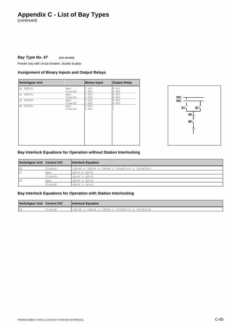
Appendix C - List of Bay Types (continued)
P439/EN M/Bd4 // AFSV.12.10190 D /// P439-304-407/408-615 C-65
Bay Type No. 47 (A21.104.R03) Feeder bay with circuit breaker, double busbar
Assignment of Binary Inputs and Output Relays
Switchgear Unit Binary Input Output Relay
Q0 (DEV01) Q1 (DEV02) Q2 (DEV03) X0 (DEV04)
Open Close(d) Open Close(d) Open Close(d) Open Close(d)
U A01 U A02 U A03 U A04 U A05 U A06 U B01 U B02
K A01 K A02 K A03 K A04 K A05 K A06 / /
Bay Interlock Equations for Operation without Station Interlocking
Switchgear Unit Control O/C Interlock Equation
Q0 Close(d) /(Q1=X) & /(Q2=X) & /(X0=X) & /(FctBl1=I) & /(FctBl2=I)
Q1 Open (Q0=0) & (Q2=0)
Close(d) (Q0=0) & (Q2=0)
Q2 Open (Q0=0) & (Q1=0)
Close(d) (Q0=0) & (Q1=0)
Bay Interlock Equations for Operation with Station Interlocking
Switchgear Unit Control O/C Interlock Equation
Q0 Close(d) /(Q1=X) & /(Q2=X) & /(X0=X) & /(FctBl1=I) & /(FctBl2=I)

Appendix C - List of Bay Types (continued)
C-66 P439/EN M/Bd4 // AFSV.12.10190 D /// P439-304-407/408-615
Bay Type No. 48 (A21.104.R04) Feeder bay with circuit breaker, double busbar
Assignment of Binary Inputs and Output Relays
Switchgear Unit Binary Input Output Relay
Q0 (DEV01) Q1 (DEV02) Q2 (DEV03) X0 (DEV04)
Open Close(d) Open Close(d) Open Close(d) Open Close(d)
U A01 U A02 U A03 U A04 U A05 U A06 U B01 U B02
K A01 K A02 K A03 K A04 K A05 K A06 K B01 K B02
Bay Interlock Equations for Operation without Station Interlocking
Switchgear Unit Control O/C Interlock Equation
Q0 Close(d) /(Q1=X) & /(Q2=X) & /(X0=X) & /(FctBl1=I) & /(FctBl2=I)
Q1 Open (Q0=0) & (Q2=0)
Close(d) (Q0=0) & (Q2=0)
Q2 Open (Q0=0) & (Q1=0)
Close(d) (Q0=0) & (Q1=0)
X0 Open (Q0=0) & (Q1=0) & (Q2=0)
Close(d) (Q0=0) & (Q1=0) & (Q2=0)
Bay Interlock Equations for Operation with Station Interlocking
Switchgear Unit Control O/C Interlock Equation
Q0 Close(d) /(Q1=X) & /(Q2=X) & /(X0=X) & /(FctBl1=I) & /(FctBl2=I)
X0 Open (Q0=0) & (Q1=0) & (Q2=0)
Close(d) (Q0=0) & (Q1=0) & (Q2=0)
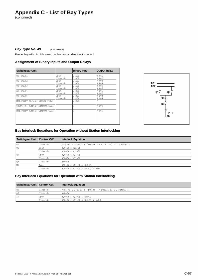
Appendix C - List of Bay Types (continued)
P439/EN M/Bd4 // AFSV.12.10190 D /// P439-304-407/408-615 C-67
Bay Type No. 49 (A21.105.M05) Feeder bay with circuit breaker, double busbar, direct motor control
Assignment of Binary Inputs and Output Relays
Switchgear Unit Binary Input Output Relay
Q0 (DEV01) Q1 (DEV02) Q2 (DEV03) X0 (DEV04) Q8 (DEV05) Mot.relay (SIG_1: Signal S012) Shunt wd. (CMD_1: Command C011) Mot.relay (CMD_1: Command C012)
Open Close(d) Open Close(d) Open Close(d) Open Close(d) Open Close(d)
U A01 U A02 U A03 U A04 U A05 U A06 U B01 U B02 U B03 U B04 U B06 / /
K A01 K A02 K A03 K A04 K A05 K A06 K B01 K B02 K B03 K B04 / K B05 K B06
Bay Interlock Equations for Operation without Station Interlocking
Switchgear Unit Control O/C Interlock Equation
Q0 Close(d) /(Q1=X) & /(Q2=X) & /(X0=X) & /(FctBl1=I) & /(FctBl2=I)
Q1 Open (Q0=0) & (Q2=0)
Close(d) (Q0=0) & (Q2=0)
Q2 Open (Q0=0) & (Q1=0)
Close(d) (Q0=0) & (Q1=0)
Q8 Close(d) (X0=0)
X0 Open (Q0=0) & (Q1=0) & (Q2=0)
Close(d) (Q0=0) & (Q1=0) & (Q2=0) & (Q8=0)
Bay Interlock Equations for Operation with Station Interlocking
Switchgear Unit Control O/C Interlock Equation
Q0 Close(d) /(Q1=X) & /(Q2=X) & /(X0=X) & /(FctBl1=I) & /(FctBl2=I)
Q8 Close(d) (X0=0)
X0 Open (Q0=0) & (Q1=0) & (Q2=0)
Close(d) (Q0=0) & (Q1=0) & (Q2=0) & (Q8=0)

Appendix C - List of Bay Types (continued)
C-68 P439/EN M/Bd4 // AFSV.12.10190 D /// P439-304-407/408-615
Bay Type No. 50 (A21.105.R01) Feeder bay with circuit breaker, double busbar
Assignment of Binary Inputs and Output Relays
Switchgear Unit Binary Input Output Relay
Q0 (DEV01) Q1 (DEV02) Q2 (DEV03) X0 (DEV04) Q8 (DEV05)
Open Close(d) Open Close(d) Open Close(d) Open Close(d) Open Close(d)
U A01 U A02 U A03 U A04 U A05 U A06 U B01 U B02 U B03 U B04
K A01 K A02 / / / / / / / /
Bay Interlock Equations for Operation without Station Interlocking
Switchgear Unit Control O/C Interlock Equation
Q0 Close(d) /(Q1=X) & /(Q2=X) & /(X0=X) & /(FctBl1=I) & /(FctBl2=I)
Bay Interlock Equations for Operation with Station Interlocking
Switchgear Unit Control O/C Interlock Equation
Q0 Close(d) /(Q1=X) & /(Q2=X) & /(X0=X) & /(FctBl1=I) & /(FctBl2=I)

Appendix C - List of Bay Types (continued)
P439/EN M/Bd4 // AFSV.12.10190 D /// P439-304-407/408-615 C-69
Bay Type No. 51 (A21.105.R03) Feeder bay with circuit breaker, double busbar
Assignment of Binary Inputs and Output Relays
Switchgear Unit Binary Input Output Relay
Q0 (DEV01) Q1 (DEV02) Q2 (DEV03) X0 (DEV04) Q8 (DEV05)
Open Close(d) Open Close(d) Open Close(d) Open Close(d) Open Close(d)
U A01 U A02 U A03 U A04 U A05 U A06 U B01 U B02 U B03 U B04
K A01 K A02 K A03 K A04 K A05 K A06 / / / /
Bay Interlock Equations for Operation without Station Interlocking
Switchgear Unit Control O/C Interlock Equation
Q0 Close(d) /(Q1=X) & /(Q2=X) & /(X0=X) & /(FctBl1=I) & /(FctBl2=I)
Q1 Open (Q0=0) & (Q2=0)
Close(d) (Q0=0) & (Q2=0)
Q2 Open (Q0=0) & (Q1=0)
Close(d) (Q0=0) & (Q1=0)
Bay Interlock Equations for Operation with Station Interlocking
Switchgear Unit Control O/C Interlock Equation
Q0 Close(d) /(Q1=X) & /(Q2=X) & /(X0=X) & /(FctBl1=I) & /(FctBl2=I)

Appendix C - List of Bay Types (continued)
C-70 P439/EN M/Bd4 // AFSV.12.10190 D /// P439-304-407/408-615
Bay Type No. 52 (A21.105.R04) Feeder bay with circuit breaker, double busbar
Assignment of Binary Inputs and Output Relays
Switchgear Unit Binary Input Output Relay
Q0 (DEV01) Q1 (DEV02) Q2 (DEV03) X0 (DEV04) Q8 (DEV05)
Open Close(d) Open Close(d) Open Close(d) Open Close(d) Open Close(d)
U A01 U A02 U A03 U A04 U A05 U A06 U B01 U B02 U B03 U B04
K A01 K A02 K A03 K A04 K A05 K A06 K B01 K B02 / /
Bay Interlock Equations for Operation without Station Interlocking
Switchgear Unit Control O/C Interlock Equation
Q0 Close(d) /(Q1=X) & /(Q2=X) & /(X0=X) & /(FctBl1=I) & /(FctBl2=I)
Q1 Open (Q0=0) & (Q2=0)
Close(d) (Q0=0) & (Q2=0)
Q2 Open (Q0=0) & (Q1=0)
Close(d) (Q0=0) & (Q1=0)
X0 Open (Q0=0) & (Q1=0) & (Q2=0)
Close(d) (Q0=0) & (Q1=0) & (Q2=0) & (Q8=0)
Bay Interlock Equations for Operation with Station Interlocking
Switchgear Unit Control O/C Interlock Equation
Q0 Close(d) /(Q1=X) & /(Q2=X) & /(X0=X) & /(FctBl1=I) & /(FctBl2=I)
X0 Open (Q0=0) & (Q1=0) & (Q2=0)
Close(d) (Q0=0) & (Q1=0) & (Q2=0) & (Q8=0)
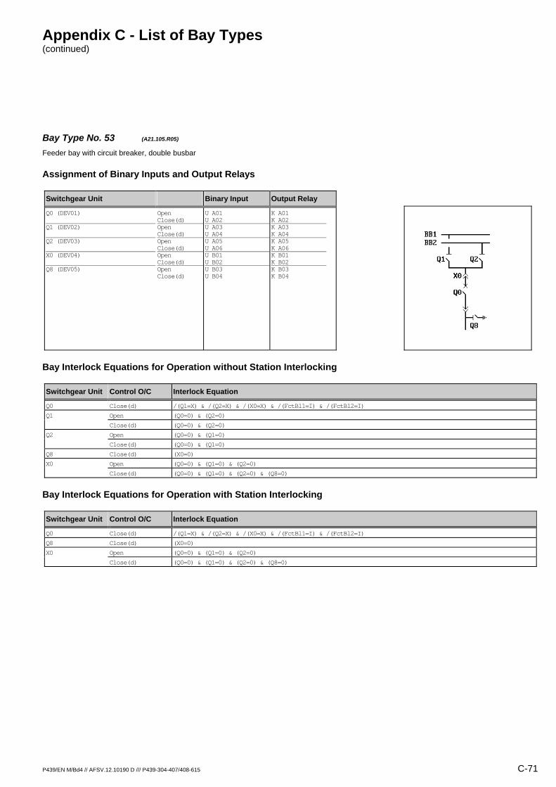
Appendix C - List of Bay Types (continued)
P439/EN M/Bd4 // AFSV.12.10190 D /// P439-304-407/408-615 C-71
Bay Type No. 53 (A21.105.R05) Feeder bay with circuit breaker, double busbar
Assignment of Binary Inputs and Output Relays
Switchgear Unit Binary Input Output Relay
Q0 (DEV01) Q1 (DEV02) Q2 (DEV03) X0 (DEV04) Q8 (DEV05)
Open Close(d) Open Close(d) Open Close(d) Open Close(d) Open Close(d)
U A01 U A02 U A03 U A04 U A05 U A06 U B01 U B02 U B03 U B04
K A01 K A02 K A03 K A04 K A05 K A06 K B01 K B02 K B03 K B04
Bay Interlock Equations for Operation without Station Interlocking
Switchgear Unit Control O/C Interlock Equation
Q0 Close(d) /(Q1=X) & /(Q2=X) & /(X0=X) & /(FctBl1=I) & /(FctBl2=I)
Q1 Open (Q0=0) & (Q2=0)
Close(d) (Q0=0) & (Q2=0)
Q2 Open (Q0=0) & (Q1=0)
Close(d) (Q0=0) & (Q1=0)
Q8 Close(d) (X0=0)
X0 Open (Q0=0) & (Q1=0) & (Q2=0)
Close(d) (Q0=0) & (Q1=0) & (Q2=0) & (Q8=0)
Bay Interlock Equations for Operation with Station Interlocking
Switchgear Unit Control O/C Interlock Equation
Q0 Close(d) /(Q1=X) & /(Q2=X) & /(X0=X) & /(FctBl1=I) & /(FctBl2=I)
Q8 Close(d) (X0=0)
X0 Open (Q0=0) & (Q1=0) & (Q2=0)
Close(d) (Q0=0) & (Q1=0) & (Q2=0) & (Q8=0)

Appendix C - List of Bay Types (continued)
C-72 P439/EN M/Bd4 // AFSV.12.10190 D /// P439-304-407/408-615
Bay Type No. 526 (A21.125.R02) Feeder bay with circuit breaker, double busbar
Assignment of Binary Inputs and Output Relays
Switchgear Unit Binary Input Output Relay
Q01 (DEV01) Q02 (DEV02) X01 (DEV03) X02 (DEV04) Q8 (DEV05) Q15 (DEV06) Q25 (DEV07)
Open Close(d) Open Close(d) Open Close(d) Open Close(d) Open Close(d) Open Close(d) Open Close(d)
U A01 U A02 U A03 U A04 U A05 U A06 U B01 U B02 U B03 U B04 U B05 U B06 U C01 U C02
K A01 K A02 K A03 K A04 / / / / / / / / / /
Bay Interlock Equations for Operation without Station Interlocking
Switchgear Unit Control O/C Interlock Equation
Q01 Close(d) /(X01=X) & /(X02=X) & (Q15=0) & (Q25=0) & /(FctBl1=I) & /(FctBl2=I)
Q02 Close(d) /(X01=X) & /(X02=X) & (Q15=0) & (Q25=0) & /(FctBl1=I) & /(FctBl2=I)
Bay Interlock Equations for Operation with Station Interlocking
Switchgear Unit Control O/C Interlock Equation
Q01 Close(d) /(X01=X) & /(X02=X) & (Q15=0) & (Q25=0) & /(FctBl1=I) & /(FctBl2=I)
Q02 Close(d) /(X01=X) & /(X02=X) & (Q15=0) & (Q25=0) & /(FctBl1=I) & /(FctBl2=I)

Appendix C - List of Bay Types (continued)
P439/EN M/Bd4 // AFSV.12.10190 D /// P439-304-407/408-615 C-73
Bay Type No. 54 (A21.204.M04) Feeder bay with switch disconnector, double busbar, direct motor control
Assignment of Binary Inputs and Output Relays
Switchgear Unit Binary Input Output Relay
Q0 (DEV01) Q1 (DEV02) Q2 (DEV03) X0 (DEV04) Mot.relay (SIG_1: Signal S012) Shunt wd. (CMD_1: Command C011) Mot.relay (CMD_1: Command C012)
Open Close(d) Open Close(d) Open Close(d) Open Close(d)
U A01 U A02 U A03 U A04 U A05 U A06 U B01 U B02 U B06 / /
K A01 K A02 K A03 K A04 K A05 K A06 K B01 K B02 / K B05 K B06
Bay Interlock Equations for Operation without Station Interlocking
Switchgear Unit Control O/C Interlock Equation
Q0 Close(d) /(Q1=X) & /(Q2=X) & /(X0=X) & /(FctBl1=I) & /(FctBl2=I)
Q1 Open (Q0=0) & (Q2=0)
Close(d) (Q0=0) & (Q2=0)
Q2 Open (Q0=0) & (Q1=0)
Close(d) (Q0=0) & (Q1=0)
X0 Open (Q0=0) & (Q1=0) & (Q2=0)
Close(d) (Q0=0) & (Q1=0) & (Q2=0)
Bay Interlock Equations for Operation with Station Interlocking
Switchgear Unit Control O/C Interlock Equation
Q0 Close(d) /(Q1=X) & /(Q2=X) & /(X0=X) & /(FctBl1=I) & /(FctBl2=I)
X0 Open (Q0=0) & (Q1=0) & (Q2=0)
Close(d) (Q0=0) & (Q1=0) & (Q2=0)

Appendix C - List of Bay Types (continued)
C-74 P439/EN M/Bd4 // AFSV.12.10190 D /// P439-304-407/408-615
Bay Type No. 55 (A21.204.R01) Feeder bay with switch disconnector, double busbar
Assignment of Binary Inputs and Output Relays
Switchgear Unit Binary Input Output Relay
Q0 (DEV01) Q1 (DEV02) Q2 (DEV03) X0 (DEV04)
Open Close(d) Open Close(d) Open Close(d) Open Close(d)
U A01 U A02 U A03 U A04 U A05 U A06 U B01 U B02
K A01 K A02 / / / / / /
Bay Interlock Equations for Operation without Station Interlocking
Switchgear Unit Control O/C Interlock Equation
Q0 Close(d) /(Q1=X) & /(Q2=X) & /(X0=X) & /(FctBl1=I) & /(FctBl2=I)
Bay Interlock Equations for Operation with Station Interlocking
Switchgear Unit Control O/C Interlock Equation
Q0 Close(d) /(Q1=X) & /(Q2=X) & /(X0=X) & /(FctBl1=I) & /(FctBl2=I)

Appendix C - List of Bay Types (continued)
P439/EN M/Bd4 // AFSV.12.10190 D /// P439-304-407/408-615 C-75
Bay Type No. 56 (A21.204.R03) Feeder bay with switch disconnector, double busbar
Assignment of Binary Inputs and Output Relays
Switchgear Unit Binary Input Output Relay
Q0 (DEV01) Q1 (DEV02) Q2 (DEV03) X0 (DEV04)
Open Close(d) Open Close(d) Open Close(d) Open Close(d)
U A01 U A02 U A03 U A04 U A05 U A06 U B01 U B02
K A01 K A02 K A03 K A04 K A05 K A06 / /
Bay Interlock Equations for Operation without Station Interlocking
Switchgear Unit Control O/C Interlock Equation
Q0 Close(d) /(Q1=X) & /(Q2=X) & /(X0=X) & /(FctBl1=I) & /(FctBl2=I)
Q1 Open (Q0=0) & (Q2=0)
Close(d) (Q0=0) & (Q2=0)
Q2 Open (Q0=0) & (Q1=0)
Close(d) (Q0=0) & (Q1=0)
Bay Interlock Equations for Operation with Station Interlocking
Switchgear Unit Control O/C Interlock Equation
Q0 Close(d) /(Q1=X) & /(Q2=X) & /(X0=X) & /(FctBl1=I) & /(FctBl2=I)

Appendix C - List of Bay Types (continued)
C-76 P439/EN M/Bd4 // AFSV.12.10190 D /// P439-304-407/408-615
Bay Type No. 57 (A21.204.R04) Feeder bay with switch disconnector, double busbar
Assignment of Binary Inputs and Output Relays
Switchgear Unit Binary Input Output Relay
Q0 (DEV01) Q1 (DEV02) Q2 (DEV03) X0 (DEV04)
Open Close(d) Open Close(d) Open Close(d) Open Close(d)
U A01 U A02 U A03 U A04 U A05 U A06 U B01 U B02
K A01 K A02 K A03 K A04 K A05 K A06 K B01 K B02
Bay Interlock Equations for Operation without Station Interlocking
Switchgear Unit Control O/C Interlock Equation
Q0 Close(d) /(Q1=X) & /(Q2=X) & /(X0=X) & /(FctBl1=I) & /(FctBl2=I)
Q1 Open (Q0=0) & (Q2=0)
Close(d) (Q0=0) & (Q2=0)
Q2 Open (Q0=0) & (Q1=0)
Close(d) (Q0=0) & (Q1=0)
X0 Open (Q0=0) & (Q1=0) & (Q2=0)
Close(d) (Q0=0) & (Q1=0) & (Q2=0)
Bay Interlock Equations for Operation with Station Interlocking
Switchgear Unit Control O/C Interlock Equation
Q0 Close(d) /(Q1=X) & /(Q2=X) & /(X0=X) & /(FctBl1=I) & /(FctBl2=I)
X0 Open (Q0=0) & (Q1=0) & (Q2=0)
Close(d) (Q0=0) & (Q1=0) & (Q2=0)

Appendix C - List of Bay Types (continued)
P439/EN M/Bd4 // AFSV.12.10190 D /// P439-304-407/408-615 C-77
Bay Type No. 58 (A21.205.M05) Feeder bay with switch disconnector, double busbar, direct motor control
Assignment of Binary Inputs and Output Relays
Switchgear Unit Binary Input Output Relay
Q0 (DEV01) Q1 (DEV02) Q2 (DEV03) X0 (DEV04) Q8 (DEV05) Mot.relay (SIG_1: Signal S012) Shunt wd. (CMD_1: Command C011) Mot.relay (CMD_1: Command C012)
Open Close(d) Open Close(d) Open Close(d) Open Close(d) Open Close(d)
U A01 U A02 U A03 U A04 U A05 U A06 U B01 U B02 U B03 U B04 U B06 / /
K A01 K A02 K A03 K A04 K A05 K A06 K B01 K B02 K B03 K B04 / K B05 K B06
Bay Interlock Equations for Operation without Station Interlocking
Switchgear Unit Control O/C Interlock Equation
Q0 Close(d) /(Q1=X) & /(Q2=X) & /(X0=X) & /(FctBl1=I) & /(FctBl2=I)
Q1 Open (Q0=0) & (Q2=0)
Close(d) (Q0=0) & (Q2=0)
Q2 Open (Q0=0) & (Q1=0)
Close(d) (Q0=0) & (Q1=0)
Q8 Close(d) (X0=0)
X0 Open (Q0=0) & (Q1=0) & (Q2=0)
Close(d) (Q0=0) & (Q1=0) & (Q2=0) & (Q8=0)
Bay Interlock Equations for Operation with Station Interlocking
Switchgear Unit Control O/C Interlock Equation
Q0 Close(d) /(Q1=X) & /(Q2=X) & /(X0=X) & /(FctBl1=I) & /(FctBl2=I)
Q8 Close(d) (X0=0)
X0 Open (Q0=0) & (Q1=0) & (Q2=0)
Close(d) (Q0=0) & (Q1=0) & (Q2=0) & (Q8=0)

Appendix C - List of Bay Types (continued)
C-78 P439/EN M/Bd4 // AFSV.12.10190 D /// P439-304-407/408-615
Bay Type No. 59 (A21.205.R01) Feeder bay with switch disconnector, double busbar
Assignment of Binary Inputs and Output Relays
Switchgear Unit Binary Input Output Relay
Q0 (DEV01) Q1 (DEV02) Q2 (DEV03) X0 (DEV04) Q8 (DEV05)
Open Close(d) Open Close(d) Open Close(d) Open Close(d) Open Close(d)
U A01 U A02 U A03 U A04 U A05 U A06 U B01 U B02 U B03 U B04
K A01 K A02 / / / / / / / /
Bay Interlock Equations for Operation without Station Interlocking
Switchgear Unit Control O/C Interlock Equation
Q0 Close(d) /(Q1=X) & /(Q2=X) & /(X0=X) & /(FctBl1=I) & /(FctBl2=I)
Bay Interlock Equations for Operation with Station Interlocking
Switchgear Unit Control O/C Interlock Equation
Q0 Close(d) /(Q1=X) & /(Q2=X) & /(X0=X) & /(FctBl1=I) & /(FctBl2=I)

Appendix C - List of Bay Types (continued)
P439/EN M/Bd4 // AFSV.12.10190 D /// P439-304-407/408-615 C-79
Bay Type No. 60 (A21.205.R03) Feeder bay with switch disconnector, double busbar
Assignment of Binary Inputs and Output Relays
Switchgear Unit Binary Input Output Relay
Q0 (DEV01) Q1 (DEV02) Q2 (DEV03) X0 (DEV04) Q8 (DEV05)
Open Close(d) Open Close(d) Open Close(d) Open Close(d) Open Close(d)
U A01 U A02 U A03 U A04 U A05 U A06 U B01 U B02 U B03 U B04
K A01 K A02 K A03 K A04 K A05 K A06 / / / /
Bay Interlock Equations for Operation without Station Interlocking
Switchgear Unit Control O/C Interlock Equation
Q0 Close(d) /(Q1=X) & /(Q2=X) & /(X0=X) & /(FctBl1=I) & /(FctBl2=I)
Q1 Open (Q0=0) & (Q2=0)
Close(d) (Q0=0) & (Q2=0)
Q2 Open (Q0=0) & (Q1=0)
Close(d) (Q0=0) & (Q1=0)
Bay Interlock Equations for Operation with Station Interlocking
Switchgear Unit Control O/C Interlock Equation
Q0 Close(d) /(Q1=X) & /(Q2=X) & /(X0=X) & /(FctBl1=I) & /(FctBl2=I)
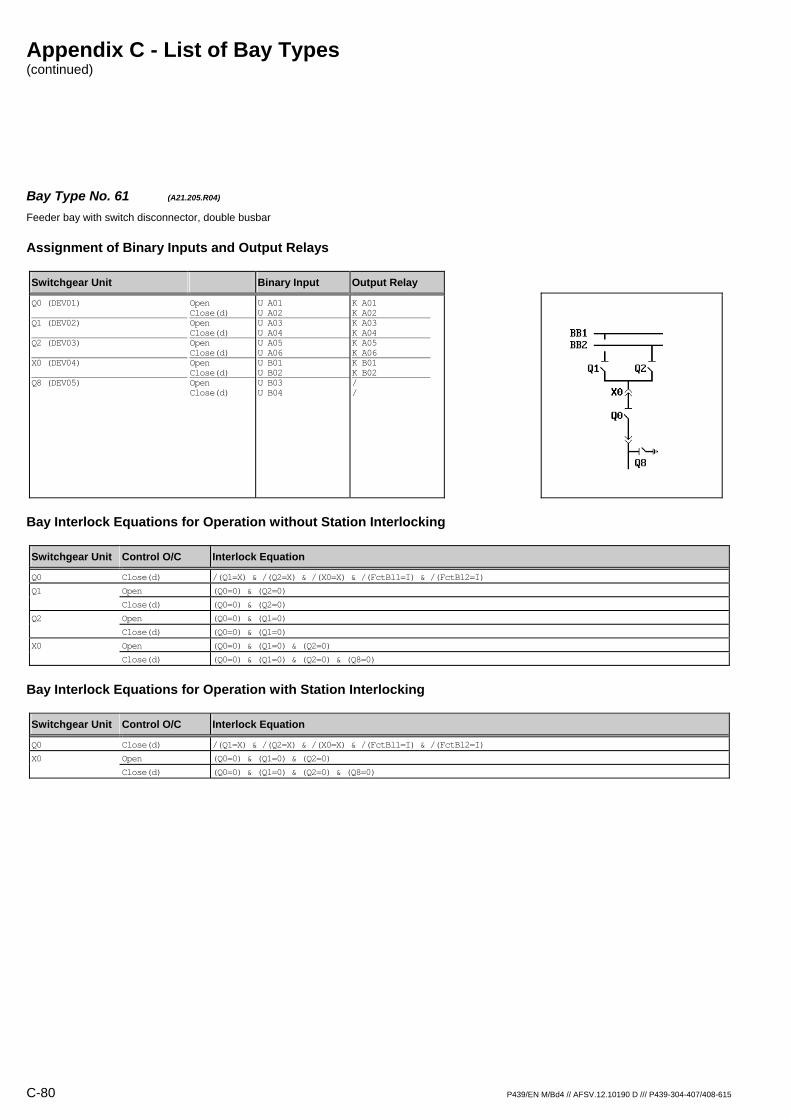
Appendix C - List of Bay Types (continued)
C-80 P439/EN M/Bd4 // AFSV.12.10190 D /// P439-304-407/408-615
Bay Type No. 61 (A21.205.R04) Feeder bay with switch disconnector, double busbar
Assignment of Binary Inputs and Output Relays
Switchgear Unit Binary Input Output Relay
Q0 (DEV01) Q1 (DEV02) Q2 (DEV03) X0 (DEV04) Q8 (DEV05)
Open Close(d) Open Close(d) Open Close(d) Open Close(d) Open Close(d)
U A01 U A02 U A03 U A04 U A05 U A06 U B01 U B02 U B03 U B04
K A01 K A02 K A03 K A04 K A05 K A06 K B01 K B02 / /
Bay Interlock Equations for Operation without Station Interlocking
Switchgear Unit Control O/C Interlock Equation
Q0 Close(d) /(Q1=X) & /(Q2=X) & /(X0=X) & /(FctBl1=I) & /(FctBl2=I)
Q1 Open (Q0=0) & (Q2=0)
Close(d) (Q0=0) & (Q2=0)
Q2 Open (Q0=0) & (Q1=0)
Close(d) (Q0=0) & (Q1=0)
X0 Open (Q0=0) & (Q1=0) & (Q2=0)
Close(d) (Q0=0) & (Q1=0) & (Q2=0) & (Q8=0)
Bay Interlock Equations for Operation with Station Interlocking
Switchgear Unit Control O/C Interlock Equation
Q0 Close(d) /(Q1=X) & /(Q2=X) & /(X0=X) & /(FctBl1=I) & /(FctBl2=I)
X0 Open (Q0=0) & (Q1=0) & (Q2=0)
Close(d) (Q0=0) & (Q1=0) & (Q2=0) & (Q8=0)

Appendix C - List of Bay Types (continued)
P439/EN M/Bd4 // AFSV.12.10190 D /// P439-304-407/408-615 C-81
Bay Type No. 62 (A21.205.R05) Feeder bay with switch disconnector, double busbar
Assignment of Binary Inputs and Output Relays
Switchgear Unit Binary Input Output Relay
Q0 (DEV01) Q1 (DEV02) Q2 (DEV03) X0 (DEV04) Q8 (DEV05)
Open Close(d) Open Close(d) Open Close(d) Open Close(d) Open Close(d)
U A01 U A02 U A03 U A04 U A05 U A06 U B01 U B02 U B03 U B04
K A01 K A02 K A03 K A04 K A05 K A06 K B01 K B02 K B03 K B04
Bay Interlock Equations for Operation without Station Interlocking
Switchgear Unit Control O/C Interlock Equation
Q0 Close(d) /(Q1=X) & /(Q2=X) & /(X0=X) & /(FctBl1=I) & /(FctBl2=I)
Q1 Open (Q0=0) & (Q2=0)
Close(d) (Q0=0) & (Q2=0)
Q2 Open (Q0=0) & (Q1=0)
Close(d) (Q0=0) & (Q1=0)
Q8 Close(d) (X0=0)
X0 Open (Q0=0) & (Q1=0) & (Q2=0)
Close(d) (Q0=0) & (Q1=0) & (Q2=0) & (Q8=0)
Bay Interlock Equations for Operation with Station Interlocking
Switchgear Unit Control O/C Interlock Equation
Q0 Close(d) /(Q1=X) & /(Q2=X) & /(X0=X) & /(FctBl1=I) & /(FctBl2=I)
Q8 Close(d) (X0=0)
X0 Open (Q0=0) & (Q1=0) & (Q2=0)
Close(d) (Q0=0) & (Q1=0) & (Q2=0) & (Q8=0)

Appendix C - List of Bay Types (continued)
C-82 P439/EN M/Bd4 // AFSV.12.10190 D /// P439-304-407/408-615
Bay Type No. 63 (A21.404.M04) Feeder bay with switch disconnector / fuse unit, double busbar, direct motor control
Assignment of Binary Inputs and Output Relays
Switchgear Unit Binary Input Output Relay
Q0 (DEV01) Q1 (DEV02) Q2 (DEV03) X0 (DEV04) F (SIG_1: Signal S011) Mot.relay (SIG_1: Signal S012) Shunt wd. (CMD_1: Command C011) Mot.relay (CMD_1: Command C012)
Open Close(d) Open Close(d) Open Close(d) Open Close(d)
U A01 U A02 U A03 U A04 U A05 U A06 U B01 U B02 U B05 U B06 / /
K A01 K A02 K A03 K A04 K A05 K A06 K B01 K B02 / / K B05 K B06
Bay Interlock Equations for Operation without Station Interlocking
Switchgear Unit Control O/C Interlock Equation
Q0 Close(d) /(Q1=X) & /(Q2=X) & /(X0=X) & /(FctBl1=I) & /(FctBl2=I)
Q1 Open (Q0=0) & (Q2=0)
Close(d) (Q0=0) & (Q2=0)
Q2 Open (Q0=0) & (Q1=0)
Close(d) (Q0=0) & (Q1=0)
X0 Open (Q0=0) & (Q1=0) & (Q2=0)
Close(d) (Q0=0) & (Q1=0) & (Q2=0)
Bay Interlock Equations for Operation with Station Interlocking
Switchgear Unit Control O/C Interlock Equation
Q0 Close(d) /(Q1=X) & /(Q2=X) & /(X0=X) & /(FctBl1=I) & /(FctBl2=I)
X0 Open (Q0=0) & (Q1=0) & (Q2=0)
Close(d) (Q0=0) & (Q1=0) & (Q2=0)

Appendix C - List of Bay Types (continued)
P439/EN M/Bd4 // AFSV.12.10190 D /// P439-304-407/408-615 C-83
Bay Type No. 64 (A21.404.R01) Feeder bay with switch disconnector / fuse unit, double busbar
Assignment of Binary Inputs and Output Relays
Switchgear Unit Binary Input Output Relay
Q0 (DEV01) Q1 (DEV02) Q2 (DEV03) X0 (DEV04) F (SIG_1: Signal S011)
Open Close(d) Open Close(d) Open Close(d) Open Close(d)
U A01 U A02 U A03 U A04 U A05 U A06 U B01 U B02 U B05
K A01 K A02 / / / / / / /
Bay Interlock Equations for Operation without Station Interlocking
Switchgear Unit Control O/C Interlock Equation
Q0 Close(d) /(Q1=X) & /(Q2=X) & /(X0=X) & /(FctBl1=I) & /(FctBl2=I)
Bay Interlock Equations for Operation with Station Interlocking
Switchgear Unit Control O/C Interlock Equation
Q0 Close(d) /(Q1=X) & /(Q2=X) & /(X0=X) & /(FctBl1=I) & /(FctBl2=I)
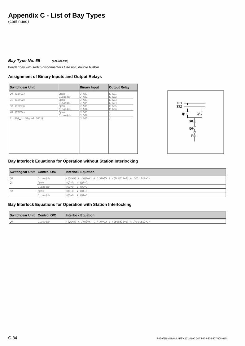
Appendix C - List of Bay Types (continued)
C-84 P439/EN M/Bd4 // AFSV.12.10190 D /// P439-304-407/408-615
Bay Type No. 65 (A21.404.R03) Feeder bay with switch disconnector / fuse unit, double busbar
Assignment of Binary Inputs and Output Relays
Switchgear Unit Binary Input Output Relay
Q0 (DEV01) Q1 (DEV02) Q2 (DEV03) X0 (DEV04) F (SIG_1: Signal S011)
Open Close(d) Open Close(d) Open Close(d) Open Close(d)
U A01 U A02 U A03 U A04 U A05 U A06 U B01 U B02 U B05
K A01 K A02 K A03 K A04 K A05 K A06 / / /
Bay Interlock Equations for Operation without Station Interlocking
Switchgear Unit Control O/C Interlock Equation
Q0 Close(d) /(Q1=X) & /(Q2=X) & /(X0=X) & /(FctBl1=I) & /(FctBl2=I)
Q1 Open (Q0=0) & (Q2=0)
Close(d) (Q0=0) & (Q2=0)
Q2 Open (Q0=0) & (Q1=0)
Close(d) (Q0=0) & (Q1=0)
Bay Interlock Equations for Operation with Station Interlocking
Switchgear Unit Control O/C Interlock Equation
Q0 Close(d) /(Q1=X) & /(Q2=X) & /(X0=X) & /(FctBl1=I) & /(FctBl2=I)
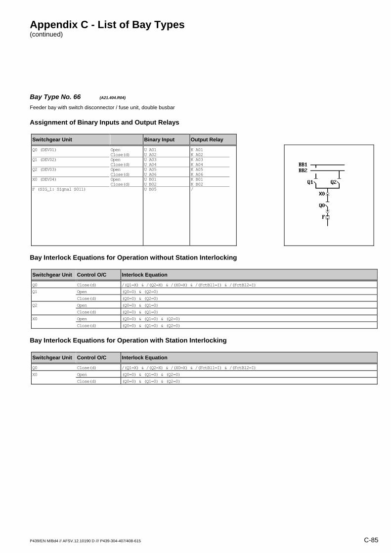
Appendix C - List of Bay Types (continued)
P439/EN M/Bd4 // AFSV.12.10190 D /// P439-304-407/408-615 C-85
Bay Type No. 66 (A21.404.R04) Feeder bay with switch disconnector / fuse unit, double busbar
Assignment of Binary Inputs and Output Relays
Switchgear Unit Binary Input Output Relay
Q0 (DEV01) Q1 (DEV02) Q2 (DEV03) X0 (DEV04) F (SIG_1: Signal S011)
Open Close(d) Open Close(d) Open Close(d) Open Close(d)
U A01 U A02 U A03 U A04 U A05 U A06 U B01 U B02 U B05
K A01 K A02 K A03 K A04 K A05 K A06 K B01 K B02 /
Bay Interlock Equations for Operation without Station Interlocking
Switchgear Unit Control O/C Interlock Equation
Q0 Close(d) /(Q1=X) & /(Q2=X) & /(X0=X) & /(FctBl1=I) & /(FctBl2=I)
Q1 Open (Q0=0) & (Q2=0)
Close(d) (Q0=0) & (Q2=0)
Q2 Open (Q0=0) & (Q1=0)
Close(d) (Q0=0) & (Q1=0)
X0 Open (Q0=0) & (Q1=0) & (Q2=0)
Close(d) (Q0=0) & (Q1=0) & (Q2=0)
Bay Interlock Equations for Operation with Station Interlocking
Switchgear Unit Control O/C Interlock Equation
Q0 Close(d) /(Q1=X) & /(Q2=X) & /(X0=X) & /(FctBl1=I) & /(FctBl2=I)
X0 Open (Q0=0) & (Q1=0) & (Q2=0)
Close(d) (Q0=0) & (Q1=0) & (Q2=0)
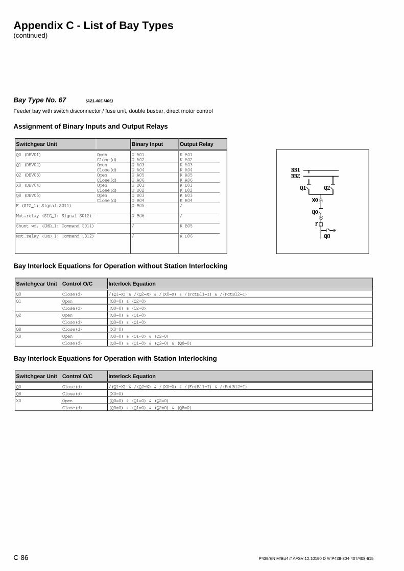
Appendix C - List of Bay Types (continued)
C-86 P439/EN M/Bd4 // AFSV.12.10190 D /// P439-304-407/408-615
Bay Type No. 67 (A21.405.M05) Feeder bay with switch disconnector / fuse unit, double busbar, direct motor control
Assignment of Binary Inputs and Output Relays
Switchgear Unit Binary Input Output Relay
Q0 (DEV01) Q1 (DEV02) Q2 (DEV03) X0 (DEV04) Q8 (DEV05) F (SIG_1: Signal S011) Mot.relay (SIG_1: Signal S012) Shunt wd. (CMD_1: Command C011) Mot.relay (CMD_1: Command C012)
Open Close(d) Open Close(d) Open Close(d) Open Close(d) Open Close(d)
U A01 U A02 U A03 U A04 U A05 U A06 U B01 U B02 U B03 U B04 U B05 U B06 / /
K A01 K A02 K A03 K A04 K A05 K A06 K B01 K B02 K B03 K B04 / / K B05 K B06
Bay Interlock Equations for Operation without Station Interlocking
Switchgear Unit Control O/C Interlock Equation
Q0 Close(d) /(Q1=X) & /(Q2=X) & /(X0=X) & /(FctBl1=I) & /(FctBl2=I)
Q1 Open (Q0=0) & (Q2=0)
Close(d) (Q0=0) & (Q2=0)
Q2 Open (Q0=0) & (Q1=0)
Close(d) (Q0=0) & (Q1=0)
Q8 Close(d) (X0=0)
X0 Open (Q0=0) & (Q1=0) & (Q2=0)
Close(d) (Q0=0) & (Q1=0) & (Q2=0) & (Q8=0)
Bay Interlock Equations for Operation with Station Interlocking
Switchgear Unit Control O/C Interlock Equation
Q0 Close(d) /(Q1=X) & /(Q2=X) & /(X0=X) & /(FctBl1=I) & /(FctBl2=I)
Q8 Close(d) (X0=0)
X0 Open (Q0=0) & (Q1=0) & (Q2=0)
Close(d) (Q0=0) & (Q1=0) & (Q2=0) & (Q8=0)
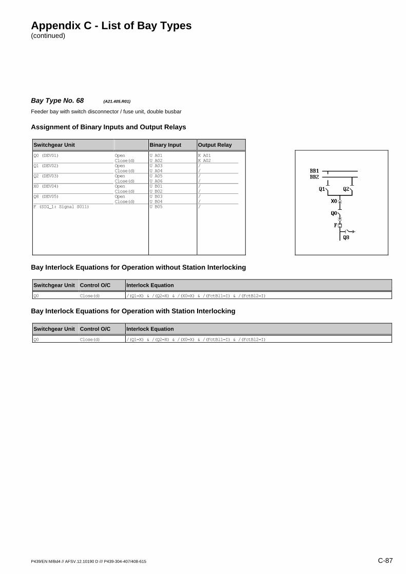
Appendix C - List of Bay Types (continued)
P439/EN M/Bd4 // AFSV.12.10190 D /// P439-304-407/408-615 C-87
Bay Type No. 68 (A21.405.R01) Feeder bay with switch disconnector / fuse unit, double busbar
Assignment of Binary Inputs and Output Relays
Switchgear Unit Binary Input Output Relay
Q0 (DEV01) Q1 (DEV02) Q2 (DEV03) X0 (DEV04) Q8 (DEV05) F (SIG_1: Signal S011)
Open Close(d) Open Close(d) Open Close(d) Open Close(d) Open Close(d)
U A01 U A02 U A03 U A04 U A05 U A06 U B01 U B02 U B03 U B04 U B05
K A01 K A02 / / / / / / / / /
Bay Interlock Equations for Operation without Station Interlocking
Switchgear Unit Control O/C Interlock Equation
Q0 Close(d) /(Q1=X) & /(Q2=X) & /(X0=X) & /(FctBl1=I) & /(FctBl2=I)
Bay Interlock Equations for Operation with Station Interlocking
Switchgear Unit Control O/C Interlock Equation
Q0 Close(d) /(Q1=X) & /(Q2=X) & /(X0=X) & /(FctBl1=I) & /(FctBl2=I)

Appendix C - List of Bay Types (continued)
C-88 P439/EN M/Bd4 // AFSV.12.10190 D /// P439-304-407/408-615
Bay Type No. 69 (A21.405.R03) Feeder bay with switch disconnector / fuse unit, double busbar
Assignment of Binary Inputs and Output Relays
Switchgear Unit Binary Input Output Relay
Q0 (DEV01) Q1 (DEV02) Q2 (DEV03) X0 (DEV04) Q8 (DEV05) F (SIG_1: Signal S011)
Open Close(d) Open Close(d) Open Close(d) Open Close(d) Open Close(d)
U A01 U A02 U A03 U A04 U A05 U A06 U B01 U B02 U B03 U B04 U B05
K A01 K A02 K A03 K A04 K A05 K A06 / / / / /
Bay Interlock Equations for Operation without Station Interlocking
Switchgear Unit Control O/C Interlock Equation
Q0 Close(d) /(Q1=X) & /(Q2=X) & /(X0=X) & /(FctBl1=I) & /(FctBl2=I)
Q1 Open (Q0=0) & (Q2=0)
Close(d) (Q0=0) & (Q2=0)
Q2 Open (Q0=0) & (Q1=0)
Close(d) (Q0=0) & (Q1=0)
Bay Interlock Equations for Operation with Station Interlocking
Switchgear Unit Control O/C Interlock Equation
Q0 Close(d) /(Q1=X) & /(Q2=X) & /(X0=X) & /(FctBl1=I) & /(FctBl2=I)
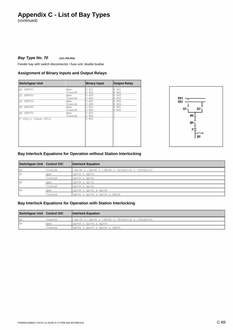
Appendix C - List of Bay Types (continued)
P439/EN M/Bd4 // AFSV.12.10190 D /// P439-304-407/408-615 C-89
Bay Type No. 70 (A21.405.R04) Feeder bay with switch disconnector / fuse unit, double busbar
Assignment of Binary Inputs and Output Relays
Switchgear Unit Binary Input Output Relay
Q0 (DEV01) Q1 (DEV02) Q2 (DEV03) X0 (DEV04) Q8 (DEV05) F (SIG_1: Signal S011)
Open Close(d) Open Close(d) Open Close(d) Open Close(d) Open Close(d)
U A01 U A02 U A03 U A04 U A05 U A06 U B01 U B02 U B03 U B04 U B05
K A01 K A02 K A03 K A04 K A05 K A06 K B01 K B02 / / /
Bay Interlock Equations for Operation without Station Interlocking
Switchgear Unit Control O/C Interlock Equation
Q0 Close(d) /(Q1=X) & /(Q2=X) & /(X0=X) & /(FctBl1=I) & /(FctBl2=I)
Q1 Open (Q0=0) & (Q2=0)
Close(d) (Q0=0) & (Q2=0)
Q2 Open (Q0=0) & (Q1=0)
Close(d) (Q0=0) & (Q1=0)
X0 Open (Q0=0) & (Q1=0) & (Q2=0)
Close(d) (Q0=0) & (Q1=0) & (Q2=0) & (Q8=0)
Bay Interlock Equations for Operation with Station Interlocking
Switchgear Unit Control O/C Interlock Equation
Q0 Close(d) /(Q1=X) & /(Q2=X) & /(X0=X) & /(FctBl1=I) & /(FctBl2=I)
X0 Open (Q0=0) & (Q1=0) & (Q2=0)
Close(d) (Q0=0) & (Q1=0) & (Q2=0) & (Q8=0)
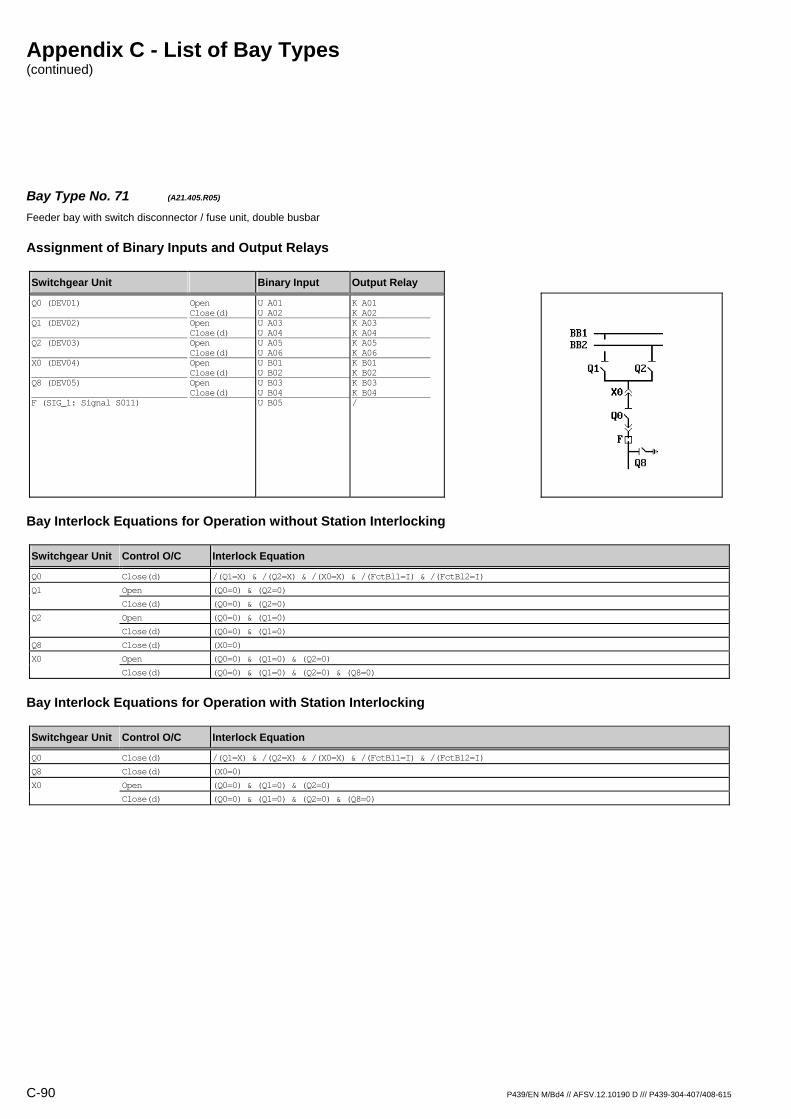
Appendix C - List of Bay Types (continued)
C-90 P439/EN M/Bd4 // AFSV.12.10190 D /// P439-304-407/408-615
Bay Type No. 71 (A21.405.R05) Feeder bay with switch disconnector / fuse unit, double busbar
Assignment of Binary Inputs and Output Relays
Switchgear Unit Binary Input Output Relay
Q0 (DEV01) Q1 (DEV02) Q2 (DEV03) X0 (DEV04) Q8 (DEV05) F (SIG_1: Signal S011)
Open Close(d) Open Close(d) Open Close(d) Open Close(d) Open Close(d)
U A01 U A02 U A03 U A04 U A05 U A06 U B01 U B02 U B03 U B04 U B05
K A01 K A02 K A03 K A04 K A05 K A06 K B01 K B02 K B03 K B04 /
Bay Interlock Equations for Operation without Station Interlocking
Switchgear Unit Control O/C Interlock Equation
Q0 Close(d) /(Q1=X) & /(Q2=X) & /(X0=X) & /(FctBl1=I) & /(FctBl2=I)
Q1 Open (Q0=0) & (Q2=0)
Close(d) (Q0=0) & (Q2=0)
Q2 Open (Q0=0) & (Q1=0)
Close(d) (Q0=0) & (Q1=0)
Q8 Close(d) (X0=0)
X0 Open (Q0=0) & (Q1=0) & (Q2=0)
Close(d) (Q0=0) & (Q1=0) & (Q2=0) & (Q8=0)
Bay Interlock Equations for Operation with Station Interlocking
Switchgear Unit Control O/C Interlock Equation
Q0 Close(d) /(Q1=X) & /(Q2=X) & /(X0=X) & /(FctBl1=I) & /(FctBl2=I)
Q8 Close(d) (X0=0)
X0 Open (Q0=0) & (Q1=0) & (Q2=0)
Close(d) (Q0=0) & (Q1=0) & (Q2=0) & (Q8=0)

Appendix C - List of Bay Types (continued)
P439/EN M/Bd4 // AFSV.12.10190 D /// P439-304-407/408-615 C-91
Bay Type No. 72 (A22.101.R02) Feeder bay with circuit breaker, double busbar
Assignment of Binary Inputs and Output Relays
Switchgear Unit Binary Input Output Relay
Q01 (DEV01) Q02 (DEV02) X01 (DEV03) X02 (DEV04) Q8 (DEV05)
Open Close(d) Open Close(d) Open Close(d) Open Close(d) Open Close(d)
U A01 U A02 U A03 U A04 U A05 U A06 U B01 U B02 U B03 U B04
K A01 K A02 K A03 K A04 / / / / / /
Bay Interlock Equations for Operation without Station Interlocking
Switchgear Unit Control O/C Interlock Equation
Q01 Close(d) (Q02=0) & /(X01=X) & /(X02=X) & /(FctBl1=I) & /(FctBl2=I)
Q02 Close(d) (Q01=0) & /(X01=X) & /(X02=X) & /(FctBl1=I) & /(FctBl2=I)
Bay Interlock Equations for Operation with Station Interlocking
Switchgear Unit Control O/C Interlock Equation
Q01 Close(d) /(X01=X) & /(X02=X) & /(FctBl1=I) & /(FctBl2=I)
Q02 Close(d) /(X01=X) & /(X02=X) & /(FctBl1=I) & /(FctBl2=I)
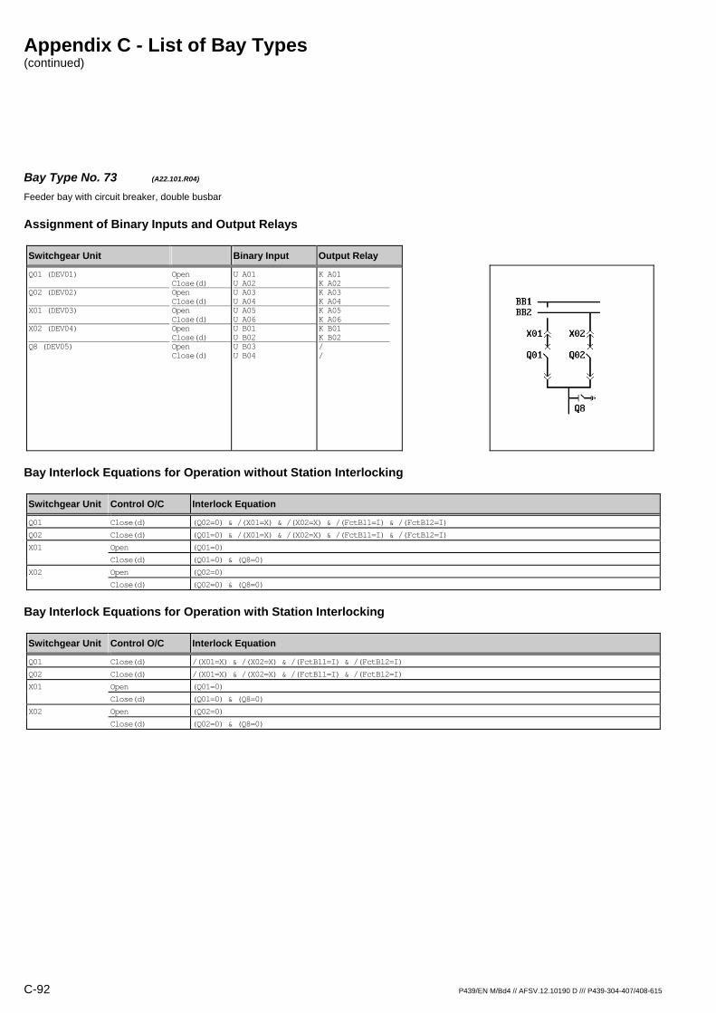
Appendix C - List of Bay Types (continued)
C-92 P439/EN M/Bd4 // AFSV.12.10190 D /// P439-304-407/408-615
Bay Type No. 73 (A22.101.R04) Feeder bay with circuit breaker, double busbar
Assignment of Binary Inputs and Output Relays
Switchgear Unit Binary Input Output Relay
Q01 (DEV01) Q02 (DEV02) X01 (DEV03) X02 (DEV04) Q8 (DEV05)
Open Close(d) Open Close(d) Open Close(d) Open Close(d) Open Close(d)
U A01 U A02 U A03 U A04 U A05 U A06 U B01 U B02 U B03 U B04
K A01 K A02 K A03 K A04 K A05 K A06 K B01 K B02 / /
Bay Interlock Equations for Operation without Station Interlocking
Switchgear Unit Control O/C Interlock Equation
Q01 Close(d) (Q02=0) & /(X01=X) & /(X02=X) & /(FctBl1=I) & /(FctBl2=I)
Q02 Close(d) (Q01=0) & /(X01=X) & /(X02=X) & /(FctBl1=I) & /(FctBl2=I)
X01 Open (Q01=0)
Close(d) (Q01=0) & (Q8=0)
X02 Open (Q02=0)
Close(d) (Q02=0) & (Q8=0)
Bay Interlock Equations for Operation with Station Interlocking
Switchgear Unit Control O/C Interlock Equation
Q01 Close(d) /(X01=X) & /(X02=X) & /(FctBl1=I) & /(FctBl2=I)
Q02 Close(d) /(X01=X) & /(X02=X) & /(FctBl1=I) & /(FctBl2=I)
X01 Open (Q01=0)
Close(d) (Q01=0) & (Q8=0)
X02 Open (Q02=0)
Close(d) (Q02=0) & (Q8=0)

Appendix C - List of Bay Types (continued)
P439/EN M/Bd4 // AFSV.12.10190 D /// P439-304-407/408-615 C-93
Bay Type No. 74 (A22.101.R05) Feeder bay with circuit breaker, double busbar
Assignment of Binary Inputs and Output Relays
Switchgear Unit Binary Input Output Relay
Q01 (DEV01) Q02 (DEV02) X01 (DEV03) X02 (DEV04) Q8 (DEV05)
Open Close(d) Open Close(d) Open Close(d) Open Close(d) Open Close(d)
U A01 U A02 U A03 U A04 U A05 U A06 U B01 U B02 U B03 U B04
K A01 K A02 K A03 K A04 K A05 K A06 K B01 K B02 K B03 K B04
Bay Interlock Equations for Operation without Station Interlocking
Switchgear Unit Control O/C Interlock Equation
Q01 Close(d) (Q02=0) & /(X01=X) & /(X02=X) & /(FctBl1=I) & /(FctBl2=I)
Q02 Close(d) (Q01=0) & /(X01=X) & /(X02=X) & /(FctBl1=I) & /(FctBl2=I)
Q8 Close(d) (X01=0) & (X02=0)
X01 Open (Q01=0)
Close(d) (Q01=0) & (Q8=0)
X02 Open (Q02=0)
Close(d) (Q02=0) & (Q8=0)
Bay Interlock Equations for Operation with Station Interlocking
Switchgear Unit Control O/C Interlock Equation
Q01 Close(d) /(X01=X) & /(X02=X) & /(FctBl1=I) & /(FctBl2=I)
Q02 Close(d) /(X01=X) & /(X02=X) & /(FctBl1=I) & /(FctBl2=I)
Q8 Close(d) (X01=0) & (X02=0)
X01 Open (Q01=0)
Close(d) (Q01=0) & (Q8=0)
X02 Open (Q02=0)
Close(d) (Q02=0) & (Q8=0)

Appendix C - List of Bay Types (continued)
C-94 P439/EN M/Bd4 // AFSV.12.10190 D /// P439-304-407/408-615
Bay Type No. 75 (A22.103.R02) Feeder bay with circuit breaker, double busbar
Assignment of Binary Inputs and Output Relays
Switchgear Unit Binary Input Output Relay
Q01 (DEV01) Q02 (DEV02) X01 (DEV03) X02 (DEV04) Q9 (DEV05) Q8 (DEV06)
Open Close(d) Open Close(d) Open Close(d) Open Close(d) Open Close(d) Open Close(d)
U A01 U A02 U A03 U A04 U A05 U A06 U B01 U B02 U B03 U B04 U B05 U B06
K A01 K A02 K A03 K A04 / / / / / / / /
Bay Interlock Equations for Operation without Station Interlocking
Switchgear Unit Control O/C Interlock Equation
Q01 Close(d) (Q02=0) & /(Q9=X) & /(X01=X) & /(X02=X) & /(FctBl1=I) & /(FctBl2=I)
Q02 Close(d) (Q01=0) & /(Q9=X) & /(X01=X) & /(X02=X) & /(FctBl1=I) & /(FctBl2=I)
Bay Interlock Equations for Operation with Station Interlocking
Switchgear Unit Control O/C Interlock Equation
Q01 Close(d) /(Q9=X) & /(X01=X) & /(X02=X) & /(FctBl1=I) & /(FctBl2=I)
Q02 Close(d) /(Q9=X) & /(X01=X) & /(X02=X) & /(FctBl1=I) & /(FctBl2=I)
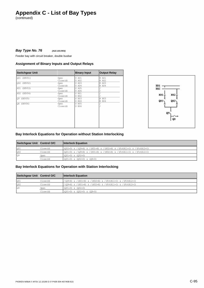
Appendix C - List of Bay Types (continued)
P439/EN M/Bd4 // AFSV.12.10190 D /// P439-304-407/408-615 C-95
Bay Type No. 76 (A22.103.R03) Feeder bay with circuit breaker, double busbar
Assignment of Binary Inputs and Output Relays
Switchgear Unit Binary Input Output Relay
Q01 (DEV01) Q02 (DEV02) X01 (DEV03) X02 (DEV04) Q9 (DEV05) Q8 (DEV06)
Open Close(d) Open Close(d) Open Close(d) Open Close(d) Open Close(d) Open Close(d)
U A01 U A02 U A03 U A04 U A05 U A06 U B01 U B02 U B03 U B04 U B05 U B06
K A01 K A02 K A03 K A04 / / / / K B03 K B04 / /
Bay Interlock Equations for Operation without Station Interlocking
Switchgear Unit Control O/C Interlock Equation
Q01 Close(d) (Q02=0) & /(Q9=X) & /(X01=X) & /(X02=X) & /(FctBl1=I) & /(FctBl2=I)
Q02 Close(d) (Q01=0) & /(Q9=X) & /(X01=X) & /(X02=X) & /(FctBl1=I) & /(FctBl2=I)
Q9 Open (Q01=0) & (Q02=0)
Close(d) (Q01=0) & (Q02=0) & (Q8=0)
Bay Interlock Equations for Operation with Station Interlocking
Switchgear Unit Control O/C Interlock Equation
Q01 Close(d) /(Q9=X) & /(X01=X) & /(X02=X) & /(FctBl1=I) & /(FctBl2=I)
Q02 Close(d) /(Q9=X) & /(X01=X) & /(X02=X) & /(FctBl1=I) & /(FctBl2=I)
Q9 Open (Q01=0) & (Q02=0)
Close(d) (Q01=0) & (Q02=0) & (Q8=0)
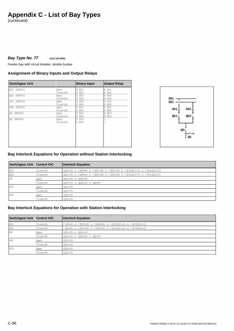
Appendix C - List of Bay Types (continued)
C-96 P439/EN M/Bd4 // AFSV.12.10190 D /// P439-304-407/408-615
Bay Type No. 77 (A22.103.R05) Feeder bay with circuit breaker, double busbar
Assignment of Binary Inputs and Output Relays
Switchgear Unit Binary Input Output Relay
Q01 (DEV01) Q02 (DEV02) X01 (DEV03) X02 (DEV04) Q9 (DEV05) Q8 (DEV06)
Open Close(d) Open Close(d) Open Close(d) Open Close(d) Open Close(d) Open Close(d)
U A01 U A02 U A03 U A04 U A05 U A06 U B01 U B02 U B03 U B04 U B05 U B06
K A01 K A02 K A03 K A04 K A05 K A06 K B01 K B02 K B03 K B04 / /
Bay Interlock Equations for Operation without Station Interlocking
Switchgear Unit Control O/C Interlock Equation
Q01 Close(d) (Q02=0) & /(Q9=X) & /(X01=X) & /(X02=X) & /(FctBl1=I) & /(FctBl2=I)
Q02 Close(d) (Q01=0) & /(Q9=X) & /(X01=X) & /(X02=X) & /(FctBl1=I) & /(FctBl2=I)
Q9 Open (Q01=0) & (Q02=0)
Close(d) (Q01=0) & (Q02=0) & (Q8=0)
X01 Open (Q01=0)
Close(d) (Q01=0)
X02 Open (Q02=0)
Close(d) (Q02=0)
Bay Interlock Equations for Operation with Station Interlocking
Switchgear Unit Control O/C Interlock Equation
Q01 Close(d) /(Q9=X) & /(X01=X) & /(X02=X) & /(FctBl1=I) & /(FctBl2=I)
Q02 Close(d) /(Q9=X) & /(X01=X) & /(X02=X) & /(FctBl1=I) & /(FctBl2=I)
Q9 Open (Q01=0) & (Q02=0)
Close(d) (Q01=0) & (Q02=0) & (Q8=0)
X01 Open (Q01=0)
Close(d) (Q01=0)
X02 Open (Q02=0)
Close(d) (Q02=0)

Appendix C - List of Bay Types (continued)
P439/EN M/Bd4 // AFSV.12.10190 D /// P439-304-407/408-615 C-97
Bay Type No. 78 (A22.103.R06) Feeder bay with circuit breaker, double busbar
Assignment of Binary Inputs and Output Relays
Switchgear Unit Binary Input Output Relay
Q01 (DEV01) Q02 (DEV02) X01 (DEV03) X02 (DEV04) Q9 (DEV05) Q8 (DEV06)
Open Close(d) Open Close(d) Open Close(d) Open Close(d) Open Close(d) Open Close(d)
U A01 U A02 U A03 U A04 U A05 U A06 U B01 U B02 U B03 U B04 U B05 U B06
K A01 K A02 K A03 K A04 K A05 K A06 K B01 K B02 K B03 K B04 K B05 K B06
Bay Interlock Equations for Operation without Station Interlocking
Switchgear Unit Control O/C Interlock Equation
Q01 Close(d) (Q02=0) & /(Q9=X) & /(X01=X) & /(X02=X) & /(FctBl1=I) & /(FctBl2=I)
Q02 Close(d) (Q01=0) & /(Q9=X) & /(X01=X) & /(X02=X) & /(FctBl1=I) & /(FctBl2=I)
Q8 Close(d) (Q9=0)
Q9 Open (Q01=0) & (Q02=0)
Close(d) (Q01=0) & (Q02=0) & (Q8=0)
X01 Open (Q01=0)
Close(d) (Q01=0)
X02 Open (Q02=0)
Close(d) (Q02=0)
Bay Interlock Equations for Operation with Station Interlocking
Switchgear Unit Control O/C Interlock Equation
Q01 Close(d) /(Q9=X) & /(X01=X) & /(X02=X) & /(FctBl1=I) & /(FctBl2=I)
Q02 Close(d) /(Q9=X) & /(X01=X) & /(X02=X) & /(FctBl1=I) & /(FctBl2=I)
Q8 Close(d) (Q9=0)
Q9 Open (Q01=0) & (Q02=0)
Close(d) (Q01=0) & (Q02=0) & (Q8=0)
X01 Open (Q01=0)
Close(d) (Q01=0)
X02 Open (Q02=0)
Close(d) (Q02=0)

Appendix C - List of Bay Types (continued)
C-98 P439/EN M/Bd4 // AFSV.12.10190 D /// P439-304-407/408-615
Bay Type No. 79 (A22.201.R02) Feeder bay with switch disconnector, double busbar
Assignment of Binary Inputs and Output Relays
Switchgear Unit Binary Input Output Relay
Q01 (DEV01) Q02 (DEV02) X01 (DEV03) X02 (DEV04) Q8 (DEV05)
Open Close(d) Open Close(d) Open Close(d) Open Close(d) Open Close(d)
U A01 U A02 U A03 U A04 U A05 U A06 U B01 U B02 U B03 U B04
K A01 K A02 K A03 K A04 / / / / / /
Bay Interlock Equations for Operation without Station Interlocking
Switchgear Unit Control O/C Interlock Equation
Q01 Close(d) (Q02=0) & /(X01=X) & /(X02=X) & /(FctBl1=I) & /(FctBl2=I)
Q02 Close(d) (Q01=0) & /(X01=X) & /(X02=X) & /(FctBl1=I) & /(FctBl2=I)
Bay Interlock Equations for Operation with Station Interlocking
Switchgear Unit Control O/C Interlock Equation
Q01 Close(d) /(X01=X) & /(X02=X) & /(FctBl1=I) & /(FctBl2=I)
Q02 Close(d) /(X01=X) & /(X02=X) & /(FctBl1=I) & /(FctBl2=I)

Appendix C - List of Bay Types (continued)
P439/EN M/Bd4 // AFSV.12.10190 D /// P439-304-407/408-615 C-99
Bay Type No. 80 (A22.201.R04) Feeder bay with switch disconnector, double busbar
Assignment of Binary Inputs and Output Relays
Switchgear Unit Binary Input Output Relay
Q01 (DEV01) Q02 (DEV02) X01 (DEV03) X02 (DEV04) Q8 (DEV05)
Open Close(d) Open Close(d) Open Close(d) Open Close(d) Open Close(d)
U A01 U A02 U A03 U A04 U A05 U A06 U B01 U B02 U B03 U B04
K A01 K A02 K A03 K A04 K A05 K A06 K B01 K B02 / /
Bay Interlock Equations for Operation without Station Interlocking
Switchgear Unit Control O/C Interlock Equation
Q01 Close(d) (Q02=0) & /(X01=X) & /(X02=X) & /(FctBl1=I) & /(FctBl2=I)
Q02 Close(d) (Q01=0) & /(X01=X) & /(X02=X) & /(FctBl1=I) & /(FctBl2=I)
X01 Open (Q01=0)
Close(d) (Q01=0) & (Q8=0)
X02 Open (Q02=0)
Close(d) (Q02=0) & (Q8=0)
Bay Interlock Equations for Operation with Station Interlocking
Switchgear Unit Control O/C Interlock Equation
Q01 Close(d) /(X01=X) & /(X02=X) & /(FctBl1=I) & /(FctBl2=I)
Q02 Close(d) /(X01=X) & /(X02=X) & /(FctBl1=I) & /(FctBl2=I)
X01 Open (Q01=0)
Close(d) (Q01=0) & (Q8=0)
X02 Open (Q02=0)
Close(d) (Q02=0) & (Q8=0)

Appendix C - List of Bay Types (continued)
C-100 P439/EN M/Bd4 // AFSV.12.10190 D /// P439-304-407/408-615
Bay Type No. 81 (A22.201.R05) Feeder bay with switch disconnector, double busbar
Assignment of Binary Inputs and Output Relays
Switchgear Unit Binary Input Output Relay
Q01 (DEV01) Q02 (DEV02) X01 (DEV03) X02 (DEV04) Q8 (DEV05)
Open Close(d) Open Close(d) Open Close(d) Open Close(d) Open Close(d)
U A01 U A02 U A03 U A04 U A05 U A06 U B01 U B02 U B03 U B04
K A01 K A02 K A03 K A04 K A05 K A06 K B01 K B02 K B03 K B04
Bay Interlock Equations for Operation without Station Interlocking
Switchgear Unit Control O/C Interlock Equation
Q01 Close(d) (Q02=0) & /(X01=X) & /(X02=X) & /(FctBl1=I) & /(FctBl2=I)
Q02 Close(d) (Q01=0) & /(X01=X) & /(X02=X) & /(FctBl1=I) & /(FctBl2=I)
Q8 Close(d) (X01=0) & (X02=0)
X01 Open (Q01=0)
Close(d) (Q01=0) & (Q8=0)
X02 Open (Q02=0)
Close(d) (Q02=0) & (Q8=0)
Bay Interlock Equations for Operation with Station Interlocking
Switchgear Unit Control O/C Interlock Equation
Q01 Close(d) /(X01=X) & /(X02=X) & /(FctBl1=I) & /(FctBl2=I)
Q02 Close(d) /(X01=X) & /(X02=X) & /(FctBl1=I) & /(FctBl2=I)
Q8 Close(d) (X01=0) & (X02=0)
X01 Open (Q01=0)
Close(d) (Q01=0) & (Q8=0)
X02 Open (Q02=0)
Close(d) (Q02=0) & (Q8=0)

Appendix C - List of Bay Types (continued)
P439/EN M/Bd4 // AFSV.12.10190 D /// P439-304-407/408-615 C-101
Bay Type No. 82 (A22.203.R02) Feeder bay with switch disconnector, double busbar
Assignment of Binary Inputs and Output Relays
Switchgear Unit Binary Input Output Relay
Q01 (DEV01) Q02 (DEV02) X01 (DEV03) X02 (DEV04) Q9 (DEV05) Q8 (DEV06)
Open Close(d) Open Close(d) Open Close(d) Open Close(d) Open Close(d) Open Close(d)
U A01 U A02 U A03 U A04 U A05 U A06 U B01 U B02 U B03 U B04 U B05 U B06
K A01 K A02 K A03 K A04 / / / / / / / /
Bay Interlock Equations for Operation without Station Interlocking
Switchgear Unit Control O/C Interlock Equation
Q01 Close(d) (Q02=0) & /(Q9=X) & /(X01=X) & /(X02=X) & /(FctBl1=I) & /(FctBl2=I)
Q02 Close(d) (Q01=0) & /(Q9=X) & /(X01=X) & /(X02=X) & /(FctBl1=I) & /(FctBl2=I)
Bay Interlock Equations for Operation with Station Interlocking
Switchgear Unit Control O/C Interlock Equation
Q01 Close(d) /(Q9=X) & /(X01=X) & /(X02=X) & /(FctBl1=I) & /(FctBl2=I)
Q02 Close(d) /(Q9=X) & /(X01=X) & /(X02=X) & /(FctBl1=I) & /(FctBl2=I)
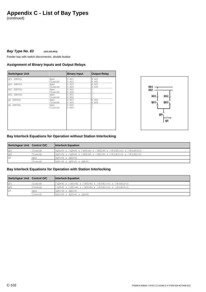
Appendix C - List of Bay Types (continued)
C-102 P439/EN M/Bd4 // AFSV.12.10190 D /// P439-304-407/408-615
Bay Type No. 83 (A22.203.R03) Feeder bay with switch disconnector, double busbar
Assignment of Binary Inputs and Output Relays
Switchgear Unit Binary Input Output Relay
Q01 (DEV01) Q02 (DEV02) X01 (DEV03) X02 (DEV04) Q9 (DEV05) Q8 (DEV06)
Open Close(d) Open Close(d) Open Close(d) Open Close(d) Open Close(d) Open Close(d)
U A01 U A02 U A03 U A04 U A05 U A06 U B01 U B02 U B03 U B04 U B05 U B06
K A01 K A02 K A03 K A04 / / / / K B03 K B04 / /
Bay Interlock Equations for Operation without Station Interlocking
Switchgear Unit Control O/C Interlock Equation
Q01 Close(d) (Q02=0) & /(Q9=X) & /(X01=X) & /(X02=X) & /(FctBl1=I) & /(FctBl2=I)
Q02 Close(d) (Q01=0) & /(Q9=X) & /(X01=X) & /(X02=X) & /(FctBl1=I) & /(FctBl2=I)
Q9 Open (Q01=0) & (Q02=0)
Close(d) (Q01=0) & (Q02=0) & (Q8=0)
Bay Interlock Equations for Operation with Station Interlocking
Switchgear Unit Control O/C Interlock Equation
Q01 Close(d) /(Q9=X) & /(X01=X) & /(X02=X) & /(FctBl1=I) & /(FctBl2=I)
Q02 Close(d) /(Q9=X) & /(X01=X) & /(X02=X) & /(FctBl1=I) & /(FctBl2=I)
Q9 Open (Q01=0) & (Q02=0)
Close(d) (Q01=0) & (Q02=0) & (Q8=0)

Appendix C - List of Bay Types (continued)
P439/EN M/Bd4 // AFSV.12.10190 D /// P439-304-407/408-615 C-103
Bay Type No. 84 (A22.203.R05) Feeder bay with switch disconnector, double busbar
Assignment of Binary Inputs and Output Relays
Switchgear Unit Binary Input Output Relay
Q01 (DEV01) Q02 (DEV02) X01 (DEV03) X02 (DEV04) Q9 (DEV05) Q8 (DEV06)
Open Close(d) Open Close(d) Open Close(d) Open Close(d) Open Close(d) Open Close(d)
U A01 U A02 U A03 U A04 U A05 U A06 U B01 U B02 U B03 U B04 U B05 U B06
K A01 K A02 K A03 K A04 K A05 K A06 K B01 K B02 K B03 K B04 / /
Bay Interlock Equations for Operation without Station Interlocking
Switchgear Unit Control O/C Interlock Equation
Q01 Close(d) (Q02=0) & /(Q9=X) & /(X01=X) & /(X02=X) & /(FctBl1=I) & /(FctBl2=I)
Q02 Close(d) (Q01=0) & /(Q9=X) & /(X01=X) & /(X02=X) & /(FctBl1=I) & /(FctBl2=I)
Q9 Open (Q01=0) & (Q02=0)
Close(d) (Q01=0) & (Q02=0) & (Q8=0)
X01 Open (Q01=0)
Close(d) (Q01=0)
X02 Open (Q02=0)
Close(d) (Q02=0)
Bay Interlock Equations for Operation with Station Interlocking
Switchgear Unit Control O/C Interlock Equation
Q01 Close(d) /(Q9=X) & /(X01=X) & /(X02=X) & /(FctBl1=I) & /(FctBl2=I)
Q02 Close(d) /(Q9=X) & /(X01=X) & /(X02=X) & /(FctBl1=I) & /(FctBl2=I)
Q9 Open (Q01=0) & (Q02=0)
Close(d) (Q01=0) & (Q02=0) & (Q8=0)
X01 Open (Q01=0)
Close(d) (Q01=0)
X02 Open (Q02=0)
Close(d) (Q02=0)

Appendix C - List of Bay Types (continued)
C-104 P439/EN M/Bd4 // AFSV.12.10190 D /// P439-304-407/408-615
Bay Type No. 85 (A22.203.R06) Feeder bay with switch disconnector, double busbar
Assignment of Binary Inputs and Output Relays
Switchgear Unit Binary Input Output Relay
Q01 (DEV01) Q02 (DEV02) X01 (DEV03) X02 (DEV04) Q9 (DEV05) Q8 (DEV06)
Open Close(d) Open Close(d) Open Close(d) Open Close(d) Open Close(d) Open Close(d)
U A01 U A02 U A03 U A04 U A05 U A06 U B01 U B02 U B03 U B04 U B05 U B06
K A01 K A02 K A03 K A04 K A05 K A06 K B01 K B02 K B03 K B04 K B05 K B06
Bay Interlock Equations for Operation without Station Interlocking
Switchgear Unit Control O/C Interlock Equation
Q01 Close(d) (Q02=0) & /(Q9=X) & /(X01=X) & /(X02=X) & /(FctBl1=I) & /(FctBl2=I)
Q02 Close(d) (Q01=0) & /(Q9=X) & /(X01=X) & /(X02=X) & /(FctBl1=I) & /(FctBl2=I)
Q8 Close(d) (Q9=0)
Q9 Open (Q01=0) & (Q02=0)
Close(d) (Q01=0) & (Q02=0) & (Q8=0)
X01 Open (Q01=0)
Close(d) (Q01=0)
X02 Open (Q02=0)
Close(d) (Q02=0)
Bay Interlock Equations for Operation with Station Interlocking
Switchgear Unit Control O/C Interlock Equation
Q01 Close(d) /(Q9=X) & /(X01=X) & /(X02=X) & /(FctBl1=I) & /(FctBl2=I)
Q02 Close(d) /(Q9=X) & /(X01=X) & /(X02=X) & /(FctBl1=I) & /(FctBl2=I)
Q8 Close(d) (Q9=0)
Q9 Open (Q01=0) & (Q02=0)
Close(d) (Q01=0) & (Q02=0) & (Q8=0)
X01 Open (Q01=0)
Close(d) (Q01=0)
X02 Open (Q02=0)
Close(d) (Q02=0)

Appendix C - List of Bay Types (continued)
P439/EN M/Bd4 // AFSV.12.10190 D /// P439-304-407/408-615 C-105
Bay Type No. 86 (A23.104.M03) Feeder bay with circuit breaker, double busbar, direct motor control
Assignment of Binary Inputs and Output Relays
Switchgear Unit Binary Input Output Relay
Q0 (DEV01) Q1 (DEV02) Q2 (DEV03) Mot.relay (SIG_1: Signal S012) Shunt wd. (CMD_1: Command C011) Mot.relay (CMD_1: Command C012)
Open Close(d) Open Close(d) Open Close(d)
U A01 U A02 U A03 U A04 U A05 U A06 U B06 / /
K A01 K A02 K A03 K A04 K A05 K A06 / K B05 K B06
Bay Interlock Equations for Operation without Station Interlocking
Switchgear Unit Control O/C Interlock Equation
Q0 Close(d) /(Q1=X) & /(Q2=X) & /(FctBl1=I) & /(FctBl2=I)
Q1 Open (Q0=0) & (Q2=0)
Close(d) (Q0=0) & (Q2=0)
Q2 Open (Q0=0) & (Q1=0)
Close(d) (Q0=0) & (Q1=0)
Bay Interlock Equations for Operation with Station Interlocking
Switchgear Unit Control O/C Interlock Equation
Q0 Close(d) /(Q1=X) & /(Q2=X) & /(FctBl1=I) & /(FctBl2=I)

Appendix C - List of Bay Types (continued)
C-106 P439/EN M/Bd4 // AFSV.12.10190 D /// P439-304-407/408-615
Bay Type No. 87 (A23.104.R01) Feeder bay with circuit breaker, double busbar
Assignment of Binary Inputs and Output Relays
Switchgear Unit Binary Input Output Relay
Q0 (DEV01) Q1 (DEV02) Q2 (DEV03)
Open Close(d) Open Close(d) Open Close(d)
U A01 U A02 U A03 U A04 U A05 U A06
K A01 K A02 / / / /
Bay Interlock Equations for Operation without Station Interlocking
Switchgear Unit Control O/C Interlock Equation
Q0 Close(d) /(Q1=X) & /(Q2=X) & /(FctBl1=I) & /(FctBl2=I)
Bay Interlock Equations for Operation with Station Interlocking
Switchgear Unit Control O/C Interlock Equation
Q0 Close(d) /(Q1=X) & /(Q2=X) & /(FctBl1=I) & /(FctBl2=I)
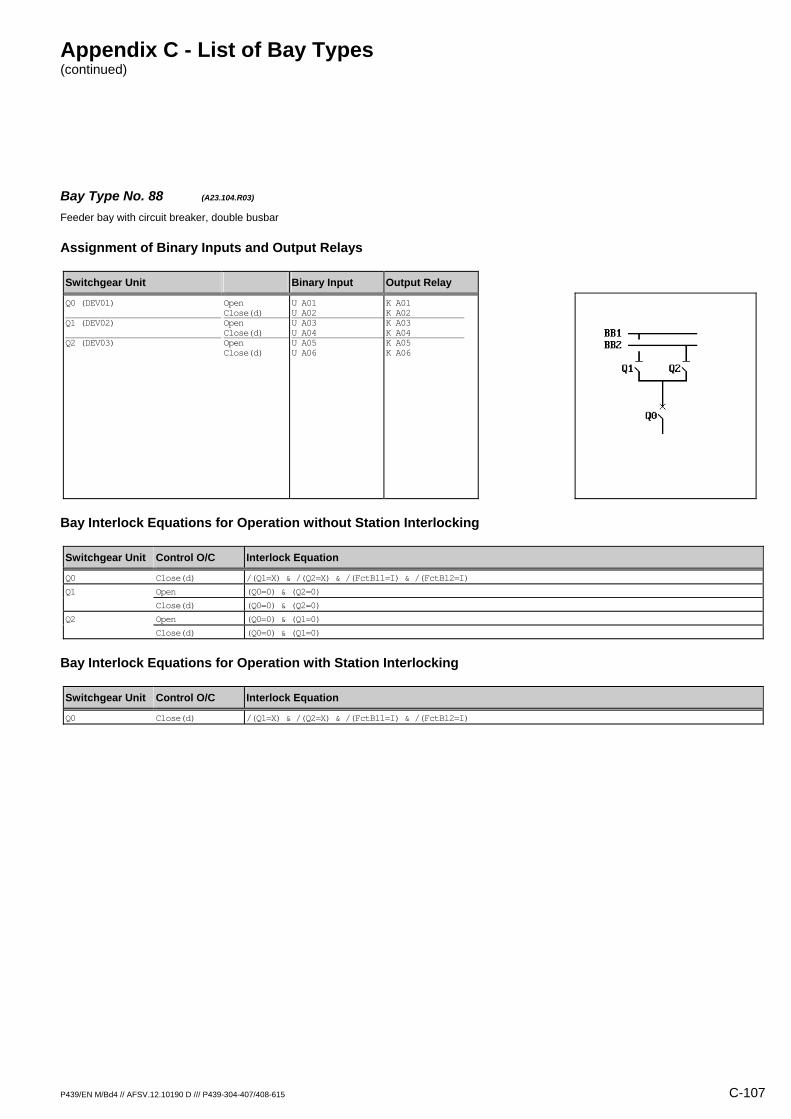
Appendix C - List of Bay Types (continued)
P439/EN M/Bd4 // AFSV.12.10190 D /// P439-304-407/408-615 C-107
Bay Type No. 88 (A23.104.R03) Feeder bay with circuit breaker, double busbar
Assignment of Binary Inputs and Output Relays
Switchgear Unit Binary Input Output Relay
Q0 (DEV01) Q1 (DEV02) Q2 (DEV03)
Open Close(d) Open Close(d) Open Close(d)
U A01 U A02 U A03 U A04 U A05 U A06
K A01 K A02 K A03 K A04 K A05 K A06
Bay Interlock Equations for Operation without Station Interlocking
Switchgear Unit Control O/C Interlock Equation
Q0 Close(d) /(Q1=X) & /(Q2=X) & /(FctBl1=I) & /(FctBl2=I)
Q1 Open (Q0=0) & (Q2=0)
Close(d) (Q0=0) & (Q2=0)
Q2 Open (Q0=0) & (Q1=0)
Close(d) (Q0=0) & (Q1=0)
Bay Interlock Equations for Operation with Station Interlocking
Switchgear Unit Control O/C Interlock Equation
Q0 Close(d) /(Q1=X) & /(Q2=X) & /(FctBl1=I) & /(FctBl2=I)

Appendix C - List of Bay Types (continued)
C-108 P439/EN M/Bd4 // AFSV.12.10190 D /// P439-304-407/408-615
Bay Type No. 89 (A23.105.M04) Feeder bay with circuit breaker, double busbar, direct motor control
Assignment of Binary Inputs and Output Relays
Switchgear Unit Binary Input Output Relay
Q0 (DEV01) Q1 (DEV02) Q2 (DEV03) Q8 (DEV04) Mot.relay (SIG_1: Signal S012) Shunt wd. (CMD_1: Command C011) Mot.relay (CMD_1: Command C012)
Open Close(d) Open Close(d) Open Close(d) Open Close(d)
U A01 U A02 U A03 U A04 U A05 U A06 U B01 U B02 U B06 / /
K A01 K A02 K A03 K A04 K A05 K A06 K B01 K B02 / K B05 K B06
Bay Interlock Equations for Operation without Station Interlocking
Switchgear Unit Control O/C Interlock Equation
Q0 Close(d) /(Q1=X) & /(Q2=X) & (Q8=0) & /(FctBl1=I) & /(FctBl2=I)
Q1 Open (Q0=0) & (Q2=0)
Close(d) (Q0=0) & (Q2=0) & (Q8=0)
Q2 Open (Q0=0) & (Q1=0)
Close(d) (Q0=0) & (Q1=0) & (Q8=0)
Q8 Close(d) (Q0=0) & (Q1=0) & (Q2=0)
Bay Interlock Equations for Operation with Station Interlocking
Switchgear Unit Control O/C Interlock Equation
Q0 Close(d) /(Q1=X) & /(Q2=X) & (Q8=0) & /(FctBl1=I) & /(FctBl2=I)
Q1 Close(d) (Q8=0)
Q2 Close(d) (Q8=0)
Q8 Close(d) (Q0=0) & (Q1=0) & (Q2=0)

Appendix C - List of Bay Types (continued)
P439/EN M/Bd4 // AFSV.12.10190 D /// P439-304-407/408-615 C-109
Bay Type No. 90 (A23.105.R01) Feeder bay with circuit breaker, double busbar
Assignment of Binary Inputs and Output Relays
Switchgear Unit Binary Input Output Relay
Q0 (DEV01) Q1 (DEV02) Q2 (DEV03) Q8 (DEV04)
Open Close(d) Open Close(d) Open Close(d) Open Close(d)
U A01 U A02 U A03 U A04 U A05 U A06 U B01 U B02
K A01 K A02 / / / / / /
Bay Interlock Equations for Operation without Station Interlocking
Switchgear Unit Control O/C Interlock Equation
Q0 Close(d) /(Q1=X) & /(Q2=X) & (Q8=0) & /(FctBl1=I) & /(FctBl2=I)
Bay Interlock Equations for Operation with Station Interlocking
Switchgear Unit Control O/C Interlock Equation
Q0 Close(d) /(Q1=X) & /(Q2=X) & (Q8=0) & /(FctBl1=I) & /(FctBl2=I)
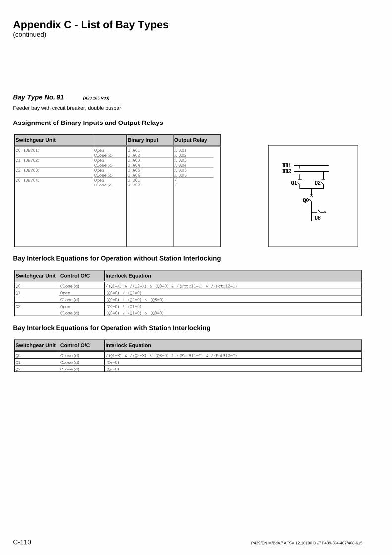
Appendix C - List of Bay Types (continued)
C-110 P439/EN M/Bd4 // AFSV.12.10190 D /// P439-304-407/408-615
Bay Type No. 91 (A23.105.R03) Feeder bay with circuit breaker, double busbar
Assignment of Binary Inputs and Output Relays
Switchgear Unit Binary Input Output Relay
Q0 (DEV01) Q1 (DEV02) Q2 (DEV03) Q8 (DEV04)
Open Close(d) Open Close(d) Open Close(d) Open Close(d)
U A01 U A02 U A03 U A04 U A05 U A06 U B01 U B02
K A01 K A02 K A03 K A04 K A05 K A06 / /
Bay Interlock Equations for Operation without Station Interlocking
Switchgear Unit Control O/C Interlock Equation
Q0 Close(d) /(Q1=X) & /(Q2=X) & (Q8=0) & /(FctBl1=I) & /(FctBl2=I)
Q1 Open (Q0=0) & (Q2=0)
Close(d) (Q0=0) & (Q2=0) & (Q8=0)
Q2 Open (Q0=0) & (Q1=0)
Close(d) (Q0=0) & (Q1=0) & (Q8=0)
Bay Interlock Equations for Operation with Station Interlocking
Switchgear Unit Control O/C Interlock Equation
Q0 Close(d) /(Q1=X) & /(Q2=X) & (Q8=0) & /(FctBl1=I) & /(FctBl2=I)
Q1 Close(d) (Q8=0)
Q2 Close(d) (Q8=0)
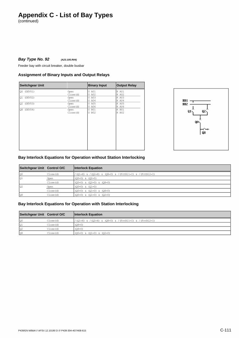
Appendix C - List of Bay Types (continued)
P439/EN M/Bd4 // AFSV.12.10190 D /// P439-304-407/408-615 C-111
Bay Type No. 92 (A23.105.R04) Feeder bay with circuit breaker, double busbar
Assignment of Binary Inputs and Output Relays
Switchgear Unit Binary Input Output Relay
Q0 (DEV01) Q1 (DEV02) Q2 (DEV03) Q8 (DEV04)
Open Close(d) Open Close(d) Open Close(d) Open Close(d)
U A01 U A02 U A03 U A04 U A05 U A06 U B01 U B02
K A01 K A02 K A03 K A04 K A05 K A06 K B01 K B02
Bay Interlock Equations for Operation without Station Interlocking
Switchgear Unit Control O/C Interlock Equation
Q0 Close(d) /(Q1=X) & /(Q2=X) & (Q8=0) & /(FctBl1=I) & /(FctBl2=I)
Q1 Open (Q0=0) & (Q2=0)
Close(d) (Q0=0) & (Q2=0) & (Q8=0)
Q2 Open (Q0=0) & (Q1=0)
Close(d) (Q0=0) & (Q1=0) & (Q8=0)
Q8 Close(d) (Q0=0) & (Q1=0) & (Q2=0)
Bay Interlock Equations for Operation with Station Interlocking
Switchgear Unit Control O/C Interlock Equation
Q0 Close(d) /(Q1=X) & /(Q2=X) & (Q8=0) & /(FctBl1=I) & /(FctBl2=I)
Q1 Close(d) (Q8=0)
Q2 Close(d) (Q8=0)
Q8 Close(d) (Q0=0) & (Q1=0) & (Q2=0)

Appendix C - List of Bay Types (continued)
C-112 P439/EN M/Bd4 // AFSV.12.10190 D /// P439-304-407/408-615
Bay Type No. 93 (A23.106.M04) Feeder bay with circuit breaker, double busbar, direct motor control
Assignment of Binary Inputs and Output Relays
Switchgear Unit Binary Input Output Relay
Q0 (DEV01) Q1 (DEV02) Q2 (DEV03) Q9 (DEV04) Mot.relay (SIG_1: Signal S012) Shunt wd. (CMD_1: Command C011) Mot.relay (CMD_1: Command C012)
Open Close(d) Open Close(d) Open Close(d) Open Close(d)
U A01 U A02 U A03 U A04 U A05 U A06 U B01 U B02 U B06 / /
K A01 K A02 K A03 K A04 K A05 K A06 K B01 K B02 / K B05 K B06
Bay Interlock Equations for Operation without Station Interlocking
Switchgear Unit Control O/C Interlock Equation
Q0 Close(d) /(Q1=X) & /(Q2=X) & /(Q9=X) & /(FctBl1=I) & /(FctBl2=I)
Q1 Open (Q0=0) & (Q2=0)
Close(d) (Q0=0) & (Q2=0)
Q2 Open (Q0=0) & (Q1=0)
Close(d) (Q0=0) & (Q1=0)
Q9 Open (Q0=0)
Close(d) (Q0=0)
Bay Interlock Equations for Operation with Station Interlocking
Switchgear Unit Control O/C Interlock Equation
Q0 Close(d) /(Q1=X) & /(Q2=X) & /(Q9=X) & /(FctBl1=I) & /(FctBl2=I)
Q9 Open (Q0=0)
Close(d) (Q0=0)

Appendix C - List of Bay Types (continued)
P439/EN M/Bd4 // AFSV.12.10190 D /// P439-304-407/408-615 C-113
Bay Type No. 94 (A23.106.R01) Feeder bay with circuit breaker, double busbar
Assignment of Binary Inputs and Output Relays
Switchgear Unit Binary Input Output Relay
Q0 (DEV01) Q1 (DEV02) Q2 (DEV03) Q9 (DEV04)
Open Close(d) Open Close(d) Open Close(d) Open Close(d)
U A01 U A02 U A03 U A04 U A05 U A06 U B01 U B02
K A01 K A02 / / / / / /
Bay Interlock Equations for Operation without Station Interlocking
Switchgear Unit Control O/C Interlock Equation
Q0 Close(d) /(Q1=X) & /(Q2=X) & /(Q9=X) & /(FctBl1=I) & /(FctBl2=I)
Bay Interlock Equations for Operation with Station Interlocking
Switchgear Unit Control O/C Interlock Equation
Q0 Close(d) /(Q1=X) & /(Q2=X) & /(Q9=X) & /(FctBl1=I) & /(FctBl2=I)
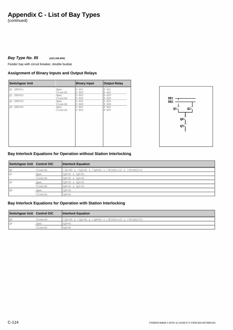
Appendix C - List of Bay Types (continued)
C-114 P439/EN M/Bd4 // AFSV.12.10190 D /// P439-304-407/408-615
Bay Type No. 95 (A23.106.R04) Feeder bay with circuit breaker, double busbar
Assignment of Binary Inputs and Output Relays
Switchgear Unit Binary Input Output Relay
Q0 (DEV01) Q1 (DEV02) Q2 (DEV03) Q9 (DEV04)
Open Close(d) Open Close(d) Open Close(d) Open Close(d)
U A01 U A02 U A03 U A04 U A05 U A06 U B01 U B02
K A01 K A02 K A03 K A04 K A05 K A06 K B01 K B02
Bay Interlock Equations for Operation without Station Interlocking
Switchgear Unit Control O/C Interlock Equation
Q0 Close(d) /(Q1=X) & /(Q2=X) & /(Q9=X) & /(FctBl1=I) & /(FctBl2=I)
Q1 Open (Q0=0) & (Q2=0)
Close(d) (Q0=0) & (Q2=0)
Q2 Open (Q0=0) & (Q1=0)
Close(d) (Q0=0) & (Q1=0)
Q9 Open (Q0=0)
Close(d) (Q0=0)
Bay Interlock Equations for Operation with Station Interlocking
Switchgear Unit Control O/C Interlock Equation
Q0 Close(d) /(Q1=X) & /(Q2=X) & /(Q9=X) & /(FctBl1=I) & /(FctBl2=I)
Q9 Open (Q0=0)
Close(d) (Q0=0)
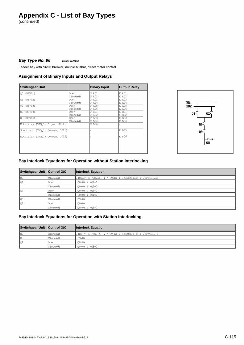
Appendix C - List of Bay Types (continued)
P439/EN M/Bd4 // AFSV.12.10190 D /// P439-304-407/408-615 C-115
Bay Type No. 96 (A23.107.M05) Feeder bay with circuit breaker, double busbar, direct motor control
Assignment of Binary Inputs and Output Relays
Switchgear Unit Binary Input Output Relay
Q0 (DEV01) Q1 (DEV02) Q2 (DEV03) Q9 (DEV04) Q8 (DEV05) Mot.relay (SIG_1: Signal S012) Shunt wd. (CMD_1: Command C011) Mot.relay (CMD_1: Command C012)
Open Close(d) Open Close(d) Open Close(d) Open Close(d) Open Close(d)
U A01 U A02 U A03 U A04 U A05 U A06 U B01 U B02 U B03 U B04 U B06 / /
K A01 K A02 K A03 K A04 K A05 K A06 K B01 K B02 K B03 K B04 / K B05 K B06
Bay Interlock Equations for Operation without Station Interlocking
Switchgear Unit Control O/C Interlock Equation
Q0 Close(d) /(Q1=X) & /(Q2=X) & /(Q9=X) & /(FctBl1=I) & /(FctBl2=I)
Q1 Open (Q0=0) & (Q2=0)
Close(d) (Q0=0) & (Q2=0)
Q2 Open (Q0=0) & (Q1=0)
Close(d) (Q0=0) & (Q1=0)
Q8 Close(d) (Q9=0)
Q9 Open (Q0=0)
Close(d) (Q0=0) & (Q8=0)
Bay Interlock Equations for Operation with Station Interlocking
Switchgear Unit Control O/C Interlock Equation
Q0 Close(d) /(Q1=X) & /(Q2=X) & /(Q9=X) & /(FctBl1=I) & /(FctBl2=I)
Q8 Close(d) (Q9=0)
Q9 Open (Q0=0)
Close(d) (Q0=0) & (Q8=0)
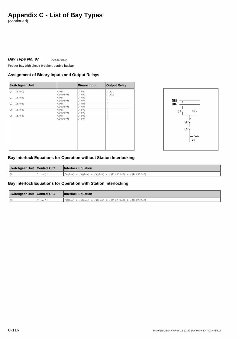
Appendix C - List of Bay Types (continued)
C-116 P439/EN M/Bd4 // AFSV.12.10190 D /// P439-304-407/408-615
Bay Type No. 97 (A23.107.R01) Feeder bay with circuit breaker, double busbar
Assignment of Binary Inputs and Output Relays
Switchgear Unit Binary Input Output Relay
Q0 (DEV01) Q1 (DEV02) Q2 (DEV03) Q9 (DEV04) Q8 (DEV05)
Open Close(d) Open Close(d) Open Close(d) Open Close(d) Open Close(d)
U A01 U A02 U A03 U A04 U A05 U A06 U B01 U B02 U B03 U B04
K A01 K A02 / / / / / / / /
Bay Interlock Equations for Operation without Station Interlocking
Switchgear Unit Control O/C Interlock Equation
Q0 Close(d) /(Q1=X) & /(Q2=X) & /(Q9=X) & /(FctBl1=I) & /(FctBl2=I)
Bay Interlock Equations for Operation with Station Interlocking
Switchgear Unit Control O/C Interlock Equation
Q0 Close(d) /(Q1=X) & /(Q2=X) & /(Q9=X) & /(FctBl1=I) & /(FctBl2=I)

Appendix C - List of Bay Types (continued)
P439/EN M/Bd4 // AFSV.12.10190 D /// P439-304-407/408-615 C-117
Bay Type No. 98 (A23.107.R04) Feeder bay with circuit breaker, double busbar
Assignment of Binary Inputs and Output Relays
Switchgear Unit Binary Input Output Relay
Q0 (DEV01) Q1 (DEV02) Q2 (DEV03) Q9 (DEV04) Q8 (DEV05)
Open Close(d) Open Close(d) Open Close(d) Open Close(d) Open Close(d)
U A01 U A02 U A03 U A04 U A05 U A06 U B01 U B02 U B03 U B04
K A01 K A02 K A03 K A04 K A05 K A06 K B01 K B02 / /
Bay Interlock Equations for Operation without Station Interlocking
Switchgear Unit Control O/C Interlock Equation
Q0 Close(d) /(Q1=X) & /(Q2=X) & /(Q9=X) & /(FctBl1=I) & /(FctBl2=I)
Q1 Open (Q0=0) & (Q2=0)
Close(d) (Q0=0) & (Q2=0)
Q2 Open (Q0=0) & (Q1=0)
Close(d) (Q0=0) & (Q1=0)
Q9 Open (Q0=0)
Close(d) (Q0=0) & (Q8=0)
Bay Interlock Equations for Operation with Station Interlocking
Switchgear Unit Control O/C Interlock Equation
Q0 Close(d) /(Q1=X) & /(Q2=X) & /(Q9=X) & /(FctBl1=I) & /(FctBl2=I)
Q9 Open (Q0=0)
Close(d) (Q0=0) & (Q8=0)
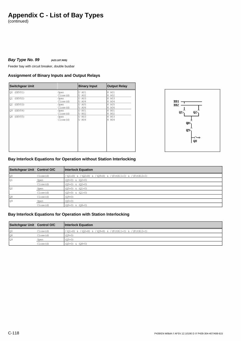
Appendix C - List of Bay Types (continued)
C-118 P439/EN M/Bd4 // AFSV.12.10190 D /// P439-304-407/408-615
Bay Type No. 99 (A23.107.R05) Feeder bay with circuit breaker, double busbar
Assignment of Binary Inputs and Output Relays
Switchgear Unit Binary Input Output Relay
Q0 (DEV01) Q1 (DEV02) Q2 (DEV03) Q9 (DEV04) Q8 (DEV05)
Open Close(d) Open Close(d) Open Close(d) Open Close(d) Open Close(d)
U A01 U A02 U A03 U A04 U A05 U A06 U B01 U B02 U B03 U B04
K A01 K A02 K A03 K A04 K A05 K A06 K B01 K B02 K B03 K B04
Bay Interlock Equations for Operation without Station Interlocking
Switchgear Unit Control O/C Interlock Equation
Q0 Close(d) /(Q1=X) & /(Q2=X) & /(Q9=X) & /(FctBl1=I) & /(FctBl2=I)
Q1 Open (Q0=0) & (Q2=0)
Close(d) (Q0=0) & (Q2=0)
Q2 Open (Q0=0) & (Q1=0)
Close(d) (Q0=0) & (Q1=0)
Q8 Close(d) (Q9=0)
Q9 Open (Q0=0)
Close(d) (Q0=0) & (Q8=0)
Bay Interlock Equations for Operation with Station Interlocking
Switchgear Unit Control O/C Interlock Equation
Q0 Close(d) /(Q1=X) & /(Q2=X) & /(Q9=X) & /(FctBl1=I) & /(FctBl2=I)
Q8 Close(d) (Q9=0)
Q9 Open (Q0=0)
Close(d) (Q0=0) & (Q8=0)
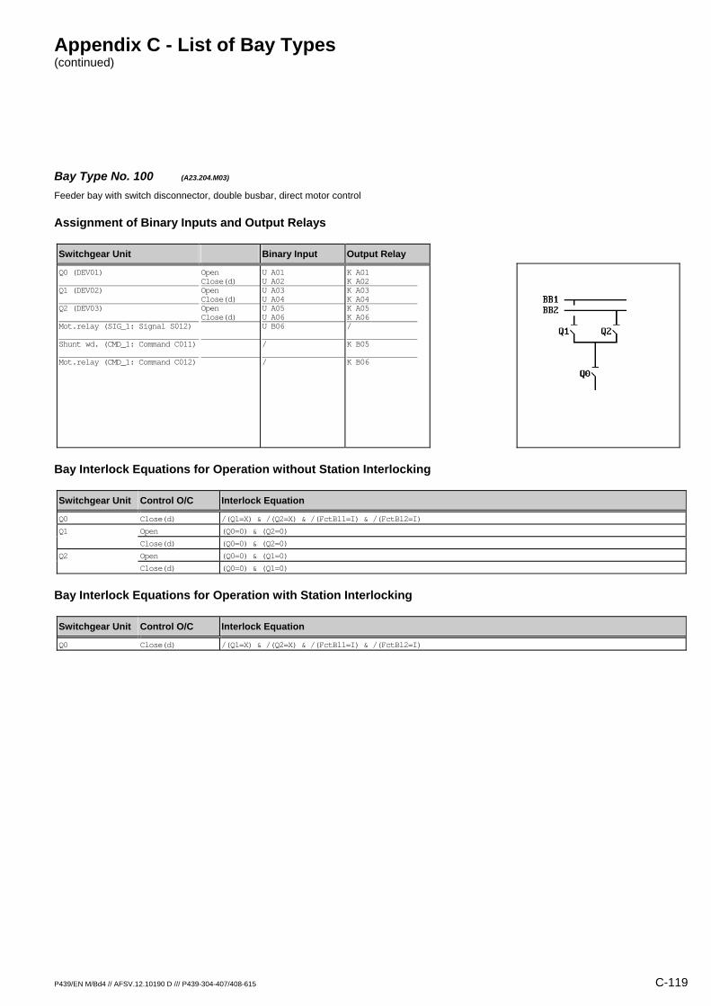
Appendix C - List of Bay Types (continued)
P439/EN M/Bd4 // AFSV.12.10190 D /// P439-304-407/408-615 C-119
Bay Type No. 100 (A23.204.M03) Feeder bay with switch disconnector, double busbar, direct motor control
Assignment of Binary Inputs and Output Relays
Switchgear Unit Binary Input Output Relay
Q0 (DEV01) Q1 (DEV02) Q2 (DEV03) Mot.relay (SIG_1: Signal S012) Shunt wd. (CMD_1: Command C011) Mot.relay (CMD_1: Command C012)
Open Close(d) Open Close(d) Open Close(d)
U A01 U A02 U A03 U A04 U A05 U A06 U B06 / /
K A01 K A02 K A03 K A04 K A05 K A06 / K B05 K B06
Bay Interlock Equations for Operation without Station Interlocking
Switchgear Unit Control O/C Interlock Equation
Q0 Close(d) /(Q1=X) & /(Q2=X) & /(FctBl1=I) & /(FctBl2=I)
Q1 Open (Q0=0) & (Q2=0)
Close(d) (Q0=0) & (Q2=0)
Q2 Open (Q0=0) & (Q1=0)
Close(d) (Q0=0) & (Q1=0)
Bay Interlock Equations for Operation with Station Interlocking
Switchgear Unit Control O/C Interlock Equation
Q0 Close(d) /(Q1=X) & /(Q2=X) & /(FctBl1=I) & /(FctBl2=I)
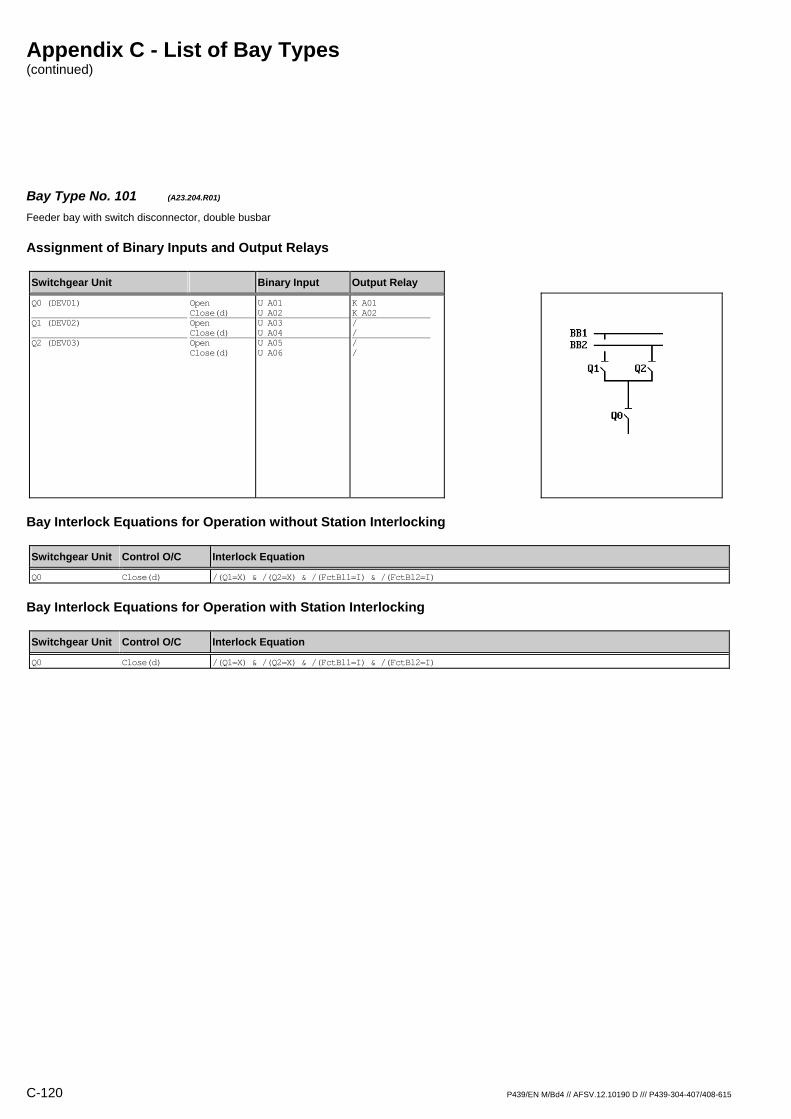
Appendix C - List of Bay Types (continued)
C-120 P439/EN M/Bd4 // AFSV.12.10190 D /// P439-304-407/408-615
Bay Type No. 101 (A23.204.R01) Feeder bay with switch disconnector, double busbar
Assignment of Binary Inputs and Output Relays
Switchgear Unit Binary Input Output Relay
Q0 (DEV01) Q1 (DEV02) Q2 (DEV03)
Open Close(d) Open Close(d) Open Close(d)
U A01 U A02 U A03 U A04 U A05 U A06
K A01 K A02 / / / /
Bay Interlock Equations for Operation without Station Interlocking
Switchgear Unit Control O/C Interlock Equation
Q0 Close(d) /(Q1=X) & /(Q2=X) & /(FctBl1=I) & /(FctBl2=I)
Bay Interlock Equations for Operation with Station Interlocking
Switchgear Unit Control O/C Interlock Equation
Q0 Close(d) /(Q1=X) & /(Q2=X) & /(FctBl1=I) & /(FctBl2=I)

Appendix C - List of Bay Types (continued)
P439/EN M/Bd4 // AFSV.12.10190 D /// P439-304-407/408-615 C-121
Bay Type No. 102 (A23.204.R03) Feeder bay with switch disconnector, double busbar
Assignment of Binary Inputs and Output Relays
Switchgear Unit Binary Input Output Relay
Q0 (DEV01) Q1 (DEV02) Q2 (DEV03)
Open Close(d) Open Close(d) Open Close(d)
U A01 U A02 U A03 U A04 U A05 U A06
K A01 K A02 K A03 K A04 K A05 K A06
Bay Interlock Equations for Operation without Station Interlocking
Switchgear Unit Control O/C Interlock Equation
Q0 Close(d) /(Q1=X) & /(Q2=X) & /(FctBl1=I) & /(FctBl2=I)
Q1 Open (Q0=0) & (Q2=0)
Close(d) (Q0=0) & (Q2=0)
Q2 Open (Q0=0) & (Q1=0)
Close(d) (Q0=0) & (Q1=0)
Bay Interlock Equations for Operation with Station Interlocking
Switchgear Unit Control O/C Interlock Equation
Q0 Close(d) /(Q1=X) & /(Q2=X) & /(FctBl1=I) & /(FctBl2=I)

Appendix C - List of Bay Types (continued)
C-122 P439/EN M/Bd4 // AFSV.12.10190 D /// P439-304-407/408-615
Bay Type No. 103 (A23.205.M04) Feeder bay with switch disconnector, double busbar, direct motor control
Assignment of Binary Inputs and Output Relays
Switchgear Unit Binary Input Output Relay
Q0 (DEV01) Q1 (DEV02) Q2 (DEV03) Q8 (DEV04) Mot.relay (SIG_1: Signal S012) Shunt wd. (CMD_1: Command C011) Mot.relay (CMD_1: Command C012)
Open Close(d) Open Close(d) Open Close(d) Open Close(d)
U A01 U A02 U A03 U A04 U A05 U A06 U B01 U B02 U B06 / /
K A01 K A02 K A03 K A04 K A05 K A06 K B01 K B02 / K B05 K B06
Bay Interlock Equations for Operation without Station Interlocking
Switchgear Unit Control O/C Interlock Equation
Q0 Close(d) /(Q1=X) & /(Q2=X) & (Q8=0) & /(FctBl1=I) & /(FctBl2=I)
Q1 Open (Q0=0) & (Q2=0)
Close(d) (Q0=0) & (Q2=0) & (Q8=0)
Q2 Open (Q0=0) & (Q1=0)
Close(d) (Q0=0) & (Q1=0) & (Q8=0)
Q8 Close(d) (Q0=0) & (Q1=0) & (Q2=0)
Bay Interlock Equations for Operation with Station Interlocking
Switchgear Unit Control O/C Interlock Equation
Q0 Close(d) /(Q1=X) & /(Q2=X) & (Q8=0) & /(FctBl1=I) & /(FctBl2=I)
Q1 Close(d) (Q8=0)
Q2 Close(d) (Q8=0)
Q8 Close(d) (Q0=0) & (Q1=0) & (Q2=0)

Appendix C - List of Bay Types (continued)
P439/EN M/Bd4 // AFSV.12.10190 D /// P439-304-407/408-615 C-123
Bay Type No. 104 (A23.205.R01) Feeder bay with switch disconnector, double busbar
Assignment of Binary Inputs and Output Relays
Switchgear Unit Binary Input Output Relay
Q0 (DEV01) Q1 (DEV02) Q2 (DEV03) Q8 (DEV04)
Open Close(d) Open Close(d) Open Close(d) Open Close(d)
U A01 U A02 U A03 U A04 U A05 U A06 U B01 U B02
K A01 K A02 / / / / / /
Bay Interlock Equations for Operation without Station Interlocking
Switchgear Unit Control O/C Interlock Equation
Q0 Close(d) /(Q1=X) & /(Q2=X) & (Q8=0) & /(FctBl1=I) & /(FctBl2=I)
Bay Interlock Equations for Operation with Station Interlocking
Switchgear Unit Control O/C Interlock Equation
Q0 Close(d) /(Q1=X) & /(Q2=X) & (Q8=0) & /(FctBl1=I) & /(FctBl2=I)

Appendix C - List of Bay Types (continued)
C-124 P439/EN M/Bd4 // AFSV.12.10190 D /// P439-304-407/408-615
Bay Type No. 105 (A23.205.R03) Feeder bay with switch disconnector, double busbar
Assignment of Binary Inputs and Output Relays
Switchgear Unit Binary Input Output Relay
Q0 (DEV01) Q1 (DEV02) Q2 (DEV03) Q8 (DEV04)
Open Close(d) Open Close(d) Open Close(d) Open Close(d)
U A01 U A02 U A03 U A04 U A05 U A06 U B01 U B02
K A01 K A02 K A03 K A04 K A05 K A06 / /
Bay Interlock Equations for Operation without Station Interlocking
Switchgear Unit Control O/C Interlock Equation
Q0 Close(d) /(Q1=X) & /(Q2=X) & (Q8=0) & /(FctBl1=I) & /(FctBl2=I)
Q1 Open (Q0=0) & (Q2=0)
Close(d) (Q0=0) & (Q2=0) & (Q8=0)
Q2 Open (Q0=0) & (Q1=0)
Close(d) (Q0=0) & (Q1=0) & (Q8=0)
Bay Interlock Equations for Operation with Station Interlocking
Switchgear Unit Control O/C Interlock Equation
Q0 Close(d) /(Q1=X) & /(Q2=X) & (Q8=0) & /(FctBl1=I) & /(FctBl2=I)
Q1 Close(d) (Q8=0)
Q2 Close(d) (Q8=0)
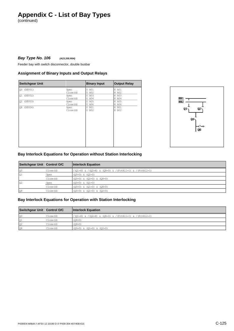
Appendix C - List of Bay Types (continued)
P439/EN M/Bd4 // AFSV.12.10190 D /// P439-304-407/408-615 C-125
Bay Type No. 106 (A23.205.R04) Feeder bay with switch disconnector, double busbar
Assignment of Binary Inputs and Output Relays
Switchgear Unit Binary Input Output Relay
Q0 (DEV01) Q1 (DEV02) Q2 (DEV03) Q8 (DEV04)
Open Close(d) Open Close(d) Open Close(d) Open Close(d)
U A01 U A02 U A03 U A04 U A05 U A06 U B01 U B02
K A01 K A02 K A03 K A04 K A05 K A06 K B01 K B02
Bay Interlock Equations for Operation without Station Interlocking
Switchgear Unit Control O/C Interlock Equation
Q0 Close(d) /(Q1=X) & /(Q2=X) & (Q8=0) & /(FctBl1=I) & /(FctBl2=I)
Q1 Open (Q0=0) & (Q2=0)
Close(d) (Q0=0) & (Q2=0) & (Q8=0)
Q2 Open (Q0=0) & (Q1=0)
Close(d) (Q0=0) & (Q1=0) & (Q8=0)
Q8 Close(d) (Q0=0) & (Q1=0) & (Q2=0)
Bay Interlock Equations for Operation with Station Interlocking
Switchgear Unit Control O/C Interlock Equation
Q0 Close(d) /(Q1=X) & /(Q2=X) & (Q8=0) & /(FctBl1=I) & /(FctBl2=I)
Q1 Close(d) (Q8=0)
Q2 Close(d) (Q8=0)
Q8 Close(d) (Q0=0) & (Q1=0) & (Q2=0)

Appendix C - List of Bay Types (continued)
C-126 P439/EN M/Bd4 // AFSV.12.10190 D /// P439-304-407/408-615
Bay Type No. 107 (A23.206.M04) Feeder bay with switch disconnector, double busbar, direct motor control
Assignment of Binary Inputs and Output Relays
Switchgear Unit Binary Input Output Relay
Q0 (DEV01) Q1 (DEV02) Q2 (DEV03) Q9 (DEV04) Mot.relay (SIG_1: Signal S012) Shunt wd. (CMD_1: Command C011) Mot.relay (CMD_1: Command C012)
Open Close(d) Open Close(d) Open Close(d) Open Close(d)
U A01 U A02 U A03 U A04 U A05 U A06 U B01 U B02 U B06 / /
K A01 K A02 K A03 K A04 K A05 K A06 K B01 K B02 / K B05 K B06
Bay Interlock Equations for Operation without Station Interlocking
Switchgear Unit Control O/C Interlock Equation
Q0 Close(d) /(Q1=X) & /(Q2=X) & /(Q9=X) & /(FctBl1=I) & /(FctBl2=I)
Q1 Open (Q0=0) & (Q2=0)
Close(d) (Q0=0) & (Q2=0)
Q2 Open (Q0=0) & (Q1=0)
Close(d) (Q0=0) & (Q1=0)
Q9 Open (Q0=0)
Close(d) (Q0=0)
Bay Interlock Equations for Operation with Station Interlocking
Switchgear Unit Control O/C Interlock Equation
Q0 Close(d) /(Q1=X) & /(Q2=X) & /(Q9=X) & /(FctBl1=I) & /(FctBl2=I)
Q9 Open (Q0=0)
Close(d) (Q0=0)

Appendix C - List of Bay Types (continued)
P439/EN M/Bd4 // AFSV.12.10190 D /// P439-304-407/408-615 C-127
Bay Type No. 108 (A23.206.R01) Feeder bay with switch disconnector, double busbar
Assignment of Binary Inputs and Output Relays
Switchgear Unit Binary Input Output Relay
Q0 (DEV01) Q1 (DEV02) Q2 (DEV03) Q9 (DEV04)
Open Close(d) Open Close(d) Open Close(d) Open Close(d)
U A01 U A02 U A03 U A04 U A05 U A06 U B01 U B02
K A01 K A02 / / / / / /
Bay Interlock Equations for Operation without Station Interlocking
Switchgear Unit Control O/C Interlock Equation
Q0 Close(d) /(Q1=X) & /(Q2=X) & /(Q9=X) & /(FctBl1=I) & /(FctBl2=I)
Bay Interlock Equations for Operation with Station Interlocking
Switchgear Unit Control O/C Interlock Equation
Q0 Close(d) /(Q1=X) & /(Q2=X) & /(Q9=X) & /(FctBl1=I) & /(FctBl2=I)

Appendix C - List of Bay Types (continued)
C-128 P439/EN M/Bd4 // AFSV.12.10190 D /// P439-304-407/408-615
Bay Type No. 109 (A23.206.R04) Feeder bay with switch disconnector, double busbar
Assignment of Binary Inputs and Output Relays
Switchgear Unit Binary Input Output Relay
Q0 (DEV01) Q1 (DEV02) Q2 (DEV03) Q9 (DEV04)
Open Close(d) Open Close(d) Open Close(d) Open Close(d)
U A01 U A02 U A03 U A04 U A05 U A06 U B01 U B02
K A01 K A02 K A03 K A04 K A05 K A06 K B01 K B02
Bay Interlock Equations for Operation without Station Interlocking
Switchgear Unit Control O/C Interlock Equation
Q0 Close(d) /(Q1=X) & /(Q2=X) & /(Q9=X) & /(FctBl1=I) & /(FctBl2=I)
Q1 Open (Q0=0) & (Q2=0)
Close(d) (Q0=0) & (Q2=0)
Q2 Open (Q0=0) & (Q1=0)
Close(d) (Q0=0) & (Q1=0)
Q9 Open (Q0=0)
Close(d) (Q0=0)
Bay Interlock Equations for Operation with Station Interlocking
Switchgear Unit Control O/C Interlock Equation
Q0 Close(d) /(Q1=X) & /(Q2=X) & /(Q9=X) & /(FctBl1=I) & /(FctBl2=I)
Q9 Open (Q0=0)
Close(d) (Q0=0)

Appendix C - List of Bay Types (continued)
P439/EN M/Bd4 // AFSV.12.10190 D /// P439-304-407/408-615 C-129
Bay Type No. 110 (A23.207.M05) Feeder bay with switch disconnector, double busbar, direct motor control
Assignment of Binary Inputs and Output Relays
Switchgear Unit Binary Input Output Relay
Q0 (DEV01) Q1 (DEV02) Q2 (DEV03) Q9 (DEV04) Q8 (DEV05) Mot.relay (SIG_1: Signal S012) Shunt wd. (CMD_1: Command C011) Mot.relay (CMD_1: Command C012)
Open Close(d) Open Close(d) Open Close(d) Open Close(d) Open Close(d)
U A01 U A02 U A03 U A04 U A05 U A06 U B01 U B02 U B03 U B04 U B06 / /
K A01 K A02 K A03 K A04 K A05 K A06 K B01 K B02 K B03 K B04 / K B05 K B06
Bay Interlock Equations for Operation without Station Interlocking
Switchgear Unit Control O/C Interlock Equation
Q0 Close(d) /(Q1=X) & /(Q2=X) & /(Q9=X) & /(FctBl1=I) & /(FctBl2=I)
Q1 Open (Q0=0) & (Q2=0)
Close(d) (Q0=0) & (Q2=0)
Q2 Open (Q0=0) & (Q1=0)
Close(d) (Q0=0) & (Q1=0)
Q8 Close(d) (Q9=0)
Q9 Open (Q0=0)
Close(d) (Q0=0) & (Q8=0)
Bay Interlock Equations for Operation with Station Interlocking
Switchgear Unit Control O/C Interlock Equation
Q0 Close(d) /(Q1=X) & /(Q2=X) & /(Q9=X) & /(FctBl1=I) & /(FctBl2=I)
Q8 Close(d) (Q9=0)
Q9 Open (Q0=0)
Close(d) (Q0=0) & (Q8=0)

Appendix C - List of Bay Types (continued)
C-130 P439/EN M/Bd4 // AFSV.12.10190 D /// P439-304-407/408-615
Bay Type No. 111 (A23.207.R01) Feeder bay with switch disconnector, double busbar
Assignment of Binary Inputs and Output Relays
Switchgear Unit Binary Input Output Relay
Q0 (DEV01) Q1 (DEV02) Q2 (DEV03) Q9 (DEV04) Q8 (DEV05)
Open Close(d) Open Close(d) Open Close(d) Open Close(d) Open Close(d)
U A01 U A02 U A03 U A04 U A05 U A06 U B01 U B02 U B03 U B04
K A01 K A02 / / / / / / / /
Bay Interlock Equations for Operation without Station Interlocking
Switchgear Unit Control O/C Interlock Equation
Q0 Close(d) /(Q1=X) & /(Q2=X) & /(Q9=X) & /(FctBl1=I) & /(FctBl2=I)
Bay Interlock Equations for Operation with Station Interlocking
Switchgear Unit Control O/C Interlock Equation
Q0 Close(d) /(Q1=X) & /(Q2=X) & /(Q9=X) & /(FctBl1=I) & /(FctBl2=I)

Appendix C - List of Bay Types (continued)
P439/EN M/Bd4 // AFSV.12.10190 D /// P439-304-407/408-615 C-131
Bay Type No. 112 (A23.207.R04) Feeder bay with switch disconnector, double busbar
Assignment of Binary Inputs and Output Relays
Switchgear Unit Binary Input Output Relay
Q0 (DEV01) Q1 (DEV02) Q2 (DEV03) Q9 (DEV04) Q8 (DEV05)
Open Close(d) Open Close(d) Open Close(d) Open Close(d) Open Close(d)
U A01 U A02 U A03 U A04 U A05 U A06 U B01 U B02 U B03 U B04
K A01 K A02 K A03 K A04 K A05 K A06 K B01 K B02 / /
Bay Interlock Equations for Operation without Station Interlocking
Switchgear Unit Control O/C Interlock Equation
Q0 Close(d) /(Q1=X) & /(Q2=X) & /(Q9=X) & /(FctBl1=I) & /(FctBl2=I)
Q1 Open (Q0=0) & (Q2=0)
Close(d) (Q0=0) & (Q2=0)
Q2 Open (Q0=0) & (Q1=0)
Close(d) (Q0=0) & (Q1=0)
Q9 Open (Q0=0)
Close(d) (Q0=0) & (Q8=0)
Bay Interlock Equations for Operation with Station Interlocking
Switchgear Unit Control O/C Interlock Equation
Q0 Close(d) /(Q1=X) & /(Q2=X) & /(Q9=X) & /(FctBl1=I) & /(FctBl2=I)
Q9 Open (Q0=0)
Close(d) (Q0=0) & (Q8=0)

Appendix C - List of Bay Types (continued)
C-132 P439/EN M/Bd4 // AFSV.12.10190 D /// P439-304-407/408-615
Bay Type No. 113 (A23.207.R05) Feeder bay with switch disconnector, double busbar
Assignment of Binary Inputs and Output Relays
Switchgear Unit Binary Input Output Relay
Q0 (DEV01) Q1 (DEV02) Q2 (DEV03) Q9 (DEV04) Q8 (DEV05)
Open Close(d) Open Close(d) Open Close(d) Open Close(d) Open Close(d)
U A01 U A02 U A03 U A04 U A05 U A06 U B01 U B02 U B03 U B04
K A01 K A02 K A03 K A04 K A05 K A06 K B01 K B02 K B03 K B04
Bay Interlock Equations for Operation without Station Interlocking
Switchgear Unit Control O/C Interlock Equation
Q0 Close(d) /(Q1=X) & /(Q2=X) & /(Q9=X) & /(FctBl1=I) & /(FctBl2=I)
Q1 Open (Q0=0) & (Q2=0)
Close(d) (Q0=0) & (Q2=0)
Q2 Open (Q0=0) & (Q1=0)
Close(d) (Q0=0) & (Q1=0)
Q8 Close(d) (Q9=0)
Q9 Open (Q0=0)
Close(d) (Q0=0) & (Q8=0)
Bay Interlock Equations for Operation with Station Interlocking
Switchgear Unit Control O/C Interlock Equation
Q0 Close(d) /(Q1=X) & /(Q2=X) & /(Q9=X) & /(FctBl1=I) & /(FctBl2=I)
Q8 Close(d) (Q9=0)
Q9 Open (Q0=0)
Close(d) (Q0=0) & (Q8=0)

Appendix C - List of Bay Types (continued)
P439/EN M/Bd4 // AFSV.12.10190 D /// P439-304-407/408-615 C-133
Bay Type No. 114 (A23.404.M03) Feeder bay with switch disconnector / fuse unit, double busbar, direct motor control
Assignment of Binary Inputs and Output Relays
Switchgear Unit Binary Input Output Relay
Q0 (DEV01) Q1 (DEV02) Q2 (DEV03) F (SIG_1: Signal S011) Mot.relay (SIG_1: Signal S012) Shunt wd. (CMD_1: Command C011) Mot.relay (CMD_1: Command C012)
Open Close(d) Open Close(d) Open Close(d)
U A01 U A02 U A03 U A04 U A05 U A06 U B05 U B06 / /
K A01 K A02 K A03 K A04 K A05 K A06 / / K B05 K B06
Bay Interlock Equations for Operation without Station Interlocking
Switchgear Unit Control O/C Interlock Equation
Q0 Close(d) /(Q1=X) & /(Q2=X) & /(FctBl1=I) & /(FctBl2=I)
Q1 Open (Q0=0) & (Q2=0)
Close(d) (Q0=0) & (Q2=0)
Q2 Open (Q0=0) & (Q1=0)
Close(d) (Q0=0) & (Q1=0)
Bay Interlock Equations for Operation with Station Interlocking
Switchgear Unit Control O/C Interlock Equation
Q0 Close(d) /(Q1=X) & /(Q2=X) & /(FctBl1=I) & /(FctBl2=I)

Appendix C - List of Bay Types (continued)
C-134 P439/EN M/Bd4 // AFSV.12.10190 D /// P439-304-407/408-615
Bay Type No. 115 (A23.404.R01) Feeder bay with switch disconnector / fuse unit, double busbar
Assignment of Binary Inputs and Output Relays
Switchgear Unit Binary Input Output Relay
Q0 (DEV01) Q1 (DEV02) Q2 (DEV03) F (SIG_1: Signal S011)
Open Close(d) Open Close(d) Open Close(d)
U A01 U A02 U A03 U A04 U A05 U A06 U B05
K A01 K A02 / / / / /
Bay Interlock Equations for Operation without Station Interlocking
Switchgear Unit Control O/C Interlock Equation
Q0 Close(d) /(Q1=X) & /(Q2=X) & /(FctBl1=I) & /(FctBl2=I)
Bay Interlock Equations for Operation with Station Interlocking
Switchgear Unit Control O/C Interlock Equation
Q0 Close(d) /(Q1=X) & /(Q2=X) & /(FctBl1=I) & /(FctBl2=I)

Appendix C - List of Bay Types (continued)
P439/EN M/Bd4 // AFSV.12.10190 D /// P439-304-407/408-615 C-135
Bay Type No. 116 (A23.404.R03) Feeder bay with switch disconnector / fuse unit, double busbar
Assignment of Binary Inputs and Output Relays
Switchgear Unit Binary Input Output Relay
Q0 (DEV01) Q1 (DEV02) Q2 (DEV03) F (SIG_1: Signal S011)
Open Close(d) Open Close(d) Open Close(d)
U A01 U A02 U A03 U A04 U A05 U A06 U B05
K A01 K A02 K A03 K A04 K A05 K A06 /
Bay Interlock Equations for Operation without Station Interlocking
Switchgear Unit Control O/C Interlock Equation
Q0 Close(d) /(Q1=X) & /(Q2=X) & /(FctBl1=I) & /(FctBl2=I)
Q1 Open (Q0=0) & (Q2=0)
Close(d) (Q0=0) & (Q2=0)
Q2 Open (Q0=0) & (Q1=0)
Close(d) (Q0=0) & (Q1=0)
Bay Interlock Equations for Operation with Station Interlocking
Switchgear Unit Control O/C Interlock Equation
Q0 Close(d) /(Q1=X) & /(Q2=X) & /(FctBl1=I) & /(FctBl2=I)
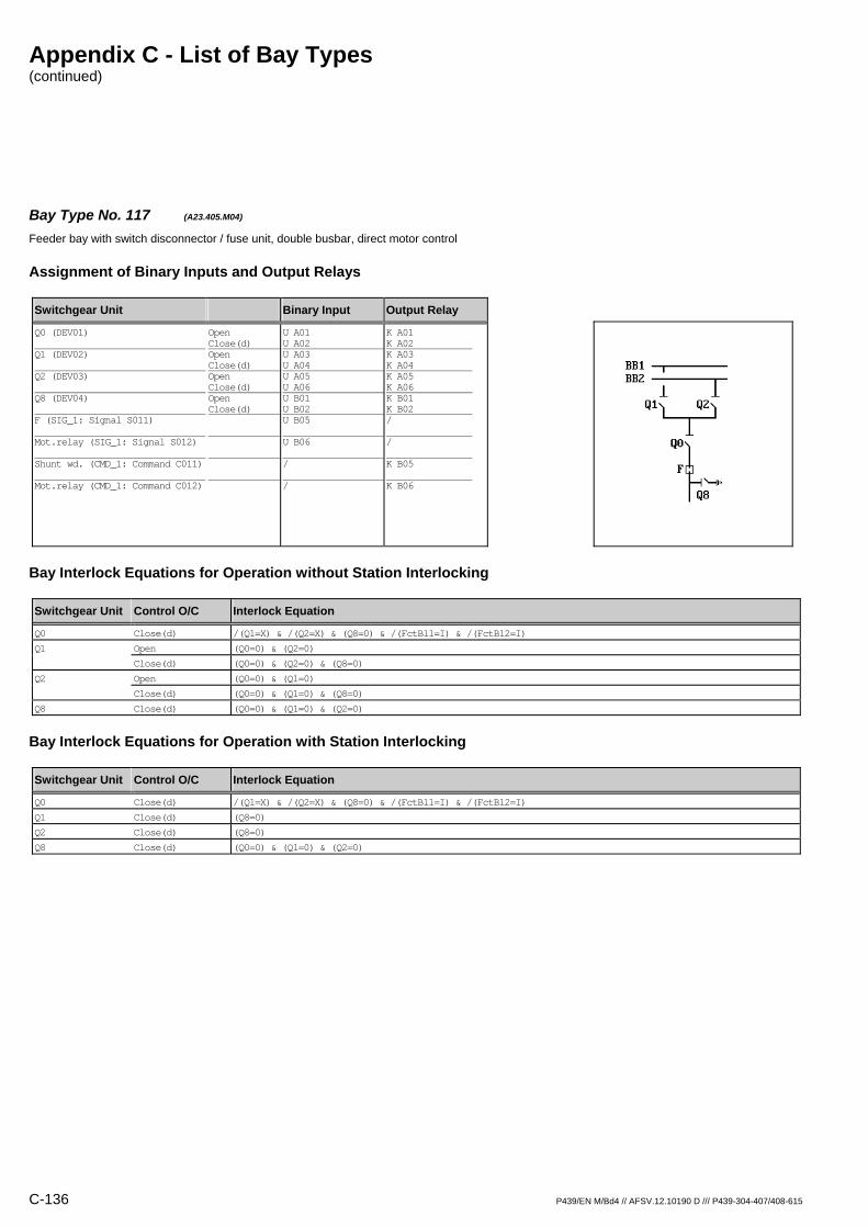
Appendix C - List of Bay Types (continued)
C-136 P439/EN M/Bd4 // AFSV.12.10190 D /// P439-304-407/408-615
Bay Type No. 117 (A23.405.M04) Feeder bay with switch disconnector / fuse unit, double busbar, direct motor control
Assignment of Binary Inputs and Output Relays
Switchgear Unit Binary Input Output Relay
Q0 (DEV01) Q1 (DEV02) Q2 (DEV03) Q8 (DEV04) F (SIG_1: Signal S011) Mot.relay (SIG_1: Signal S012) Shunt wd. (CMD_1: Command C011) Mot.relay (CMD_1: Command C012)
Open Close(d) Open Close(d) Open Close(d) Open Close(d)
U A01 U A02 U A03 U A04 U A05 U A06 U B01 U B02 U B05 U B06 / /
K A01 K A02 K A03 K A04 K A05 K A06 K B01 K B02 / / K B05 K B06
Bay Interlock Equations for Operation without Station Interlocking
Switchgear Unit Control O/C Interlock Equation
Q0 Close(d) /(Q1=X) & /(Q2=X) & (Q8=0) & /(FctBl1=I) & /(FctBl2=I)
Q1 Open (Q0=0) & (Q2=0)
Close(d) (Q0=0) & (Q2=0) & (Q8=0)
Q2 Open (Q0=0) & (Q1=0)
Close(d) (Q0=0) & (Q1=0) & (Q8=0)
Q8 Close(d) (Q0=0) & (Q1=0) & (Q2=0)
Bay Interlock Equations for Operation with Station Interlocking
Switchgear Unit Control O/C Interlock Equation
Q0 Close(d) /(Q1=X) & /(Q2=X) & (Q8=0) & /(FctBl1=I) & /(FctBl2=I)
Q1 Close(d) (Q8=0)
Q2 Close(d) (Q8=0)
Q8 Close(d) (Q0=0) & (Q1=0) & (Q2=0)

Appendix C - List of Bay Types (continued)
P439/EN M/Bd4 // AFSV.12.10190 D /// P439-304-407/408-615 C-137
Bay Type No. 118 (A23.405.R01) Feeder bay with switch disconnector / fuse unit, double busbar
Assignment of Binary Inputs and Output Relays
Switchgear Unit Binary Input Output Relay
Q0 (DEV01) Q1 (DEV02) Q2 (DEV03) Q8 (DEV04) F (SIG_1: Signal S011)
Open Close(d) Open Close(d) Open Close(d) Open Close(d)
U A01 U A02 U A03 U A04 U A05 U A06 U B01 U B02 U B05
K A01 K A02 / / / / / / /
Bay Interlock Equations for Operation without Station Interlocking
Switchgear Unit Control O/C Interlock Equation
Q0 Close(d) /(Q1=X) & /(Q2=X) & (Q8=0) & /(FctBl1=I) & /(FctBl2=I)
Bay Interlock Equations for Operation with Station Interlocking
Switchgear Unit Control O/C Interlock Equation
Q0 Close(d) /(Q1=X) & /(Q2=X) & (Q8=0) & /(FctBl1=I) & /(FctBl2=I)

Appendix C - List of Bay Types (continued)
C-138 P439/EN M/Bd4 // AFSV.12.10190 D /// P439-304-407/408-615
Bay Type No. 119 (A23.405.R03) Feeder bay with switch disconnector / fuse unit, double busbar
Assignment of Binary Inputs and Output Relays
Switchgear Unit Binary Input Output Relay
Q0 (DEV01) Q1 (DEV02) Q2 (DEV03) Q8 (DEV04) F (SIG_1: Signal S011)
Open Close(d) Open Close(d) Open Close(d) Open Close(d)
U A01 U A02 U A03 U A04 U A05 U A06 U B01 U B02 U B05
K A01 K A02 K A03 K A04 K A05 K A06 / / /
Bay Interlock Equations for Operation without Station Interlocking
Switchgear Unit Control O/C Interlock Equation
Q0 Close(d) /(Q1=X) & /(Q2=X) & (Q8=0) & /(FctBl1=I) & /(FctBl2=I)
Q1 Open (Q0=0) & (Q2=0)
Close(d) (Q0=0) & (Q2=0) & (Q8=0)
Q2 Open (Q0=0) & (Q1=0)
Close(d) (Q0=0) & (Q1=0) & (Q8=0)
Bay Interlock Equations for Operation with Station Interlocking
Switchgear Unit Control O/C Interlock Equation
Q0 Close(d) /(Q1=X) & /(Q2=X) & (Q8=0) & /(FctBl1=I) & /(FctBl2=I)
Q1 Close(d) (Q8=0)
Q2 Close(d) (Q8=0)

Appendix C - List of Bay Types (continued)
P439/EN M/Bd4 // AFSV.12.10190 D /// P439-304-407/408-615 C-139
Bay Type No. 120 (A23.405.R04) Feeder bay with switch disconnector / fuse unit, double busbar
Assignment of Binary Inputs and Output Relays
Switchgear Unit Binary Input Output Relay
Q0 (DEV01) Q1 (DEV02) Q2 (DEV03) Q8 (DEV04) F (SIG_1: Signal S011)
Open Close(d) Open Close(d) Open Close(d) Open Close(d)
U A01 U A02 U A03 U A04 U A05 U A06 U B01 U B02 U B05
K A01 K A02 K A03 K A04 K A05 K A06 K B01 K B02 /
Bay Interlock Equations for Operation without Station Interlocking
Switchgear Unit Control O/C Interlock Equation
Q0 Close(d) /(Q1=X) & /(Q2=X) & (Q8=0) & /(FctBl1=I) & /(FctBl2=I)
Q1 Open (Q0=0) & (Q2=0)
Close(d) (Q0=0) & (Q2=0) & (Q8=0)
Q2 Open (Q0=0) & (Q1=0)
Close(d) (Q0=0) & (Q1=0) & (Q8=0)
Q8 Close(d) (Q0=0) & (Q1=0) & (Q2=0)
Bay Interlock Equations for Operation with Station Interlocking
Switchgear Unit Control O/C Interlock Equation
Q0 Close(d) /(Q1=X) & /(Q2=X) & (Q8=0) & /(FctBl1=I) & /(FctBl2=I)
Q1 Close(d) (Q8=0)
Q2 Close(d) (Q8=0)
Q8 Close(d) (Q0=0) & (Q1=0) & (Q2=0)
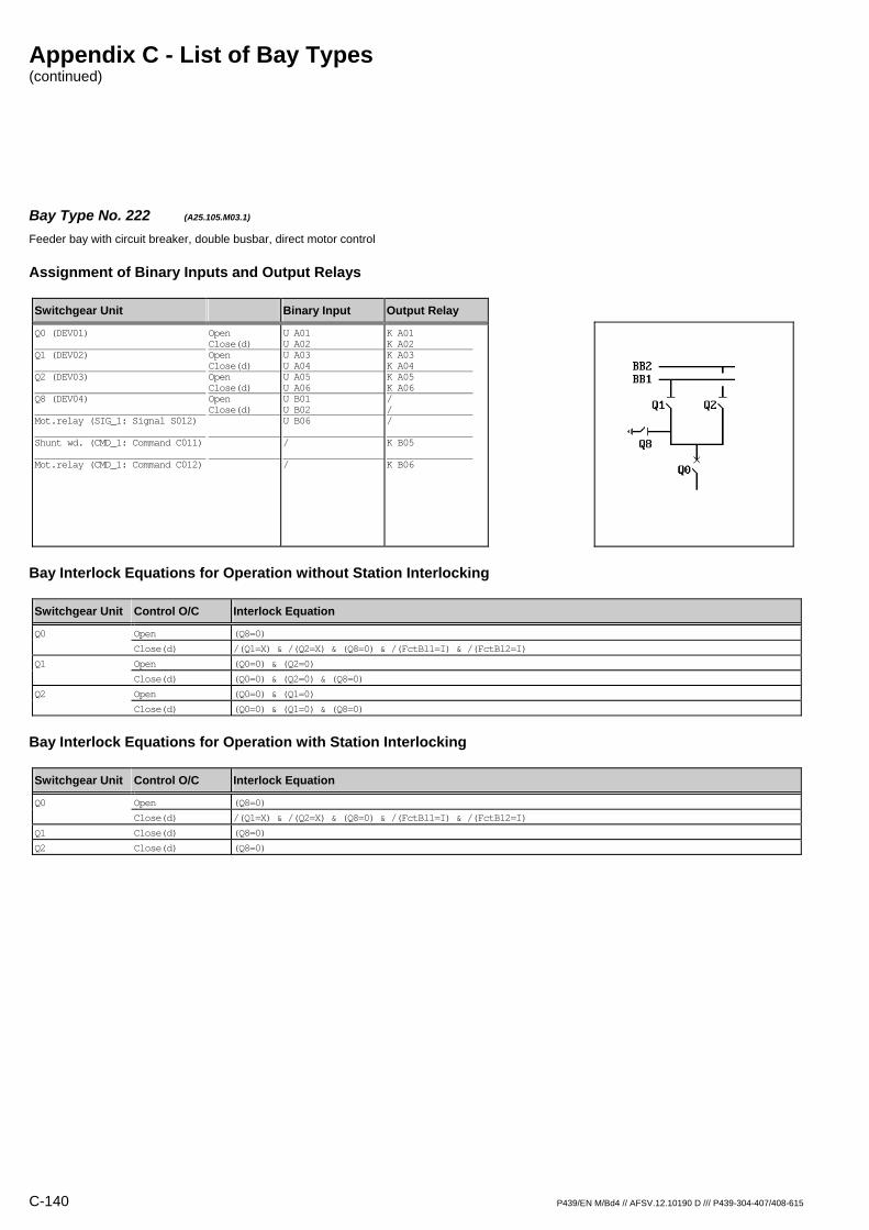
Appendix C - List of Bay Types (continued)
C-140 P439/EN M/Bd4 // AFSV.12.10190 D /// P439-304-407/408-615
Bay Type No. 222 (A25.105.M03.1) Feeder bay with circuit breaker, double busbar, direct motor control
Assignment of Binary Inputs and Output Relays
Switchgear Unit Binary Input Output Relay
Q0 (DEV01) Q1 (DEV02) Q2 (DEV03) Q8 (DEV04) Mot.relay (SIG_1: Signal S012) Shunt wd. (CMD_1: Command C011) Mot.relay (CMD_1: Command C012)
Open Close(d) Open Close(d) Open Close(d) Open Close(d)
U A01 U A02 U A03 U A04 U A05 U A06 U B01 U B02 U B06 / /
K A01 K A02 K A03 K A04 K A05 K A06 / / / K B05 K B06
Bay Interlock Equations for Operation without Station Interlocking
Switchgear Unit Control O/C Interlock Equation
Q0 Open (Q8=0)
Close(d) /(Q1=X) & /(Q2=X) & (Q8=0) & /(FctBl1=I) & /(FctBl2=I)
Q1 Open (Q0=0) & (Q2=0)
Close(d) (Q0=0) & (Q2=0) & (Q8=0)
Q2 Open (Q0=0) & (Q1=0)
Close(d) (Q0=0) & (Q1=0) & (Q8=0)
Bay Interlock Equations for Operation with Station Interlocking
Switchgear Unit Control O/C Interlock Equation
Q0 Open (Q8=0)
Close(d) /(Q1=X) & /(Q2=X) & (Q8=0) & /(FctBl1=I) & /(FctBl2=I)
Q1 Close(d) (Q8=0)
Q2 Close(d) (Q8=0)

Appendix C - List of Bay Types (continued)
P439/EN M/Bd4 // AFSV.12.10190 D /// P439-304-407/408-615 C-141
Bay Type No. 223 (A25.105.M03.2) Feeder bay with circuit breaker, double busbar, direct motor control
Assignment of Binary Inputs and Output Relays
Switchgear Unit Binary Input Output Relay
Q0 (DEV01) Q1 (DEV02) Q2 (DEV03) Q8 (DEV04) Mot.relay (SIG_1: Signal S012) Shunt wd. (CMD_1: Command C011) Mot.relay (CMD_1: Command C012)
Open Close(d) Open Close(d) Open Close(d) Open Close(d)
U A01 U A02 U A03 U A04 U A05 U A06 U B01 U B02 U B06 / /
K A01 K A02 K A03 K A04 K A05 K A06 / / / K B05 K B06
Bay Interlock Equations for Operation without Station Interlocking
Switchgear Unit Control O/C Interlock Equation
Q0 Open (Q8=0)
Close(d) /(Q1=X) & /(Q2=X) & (Q8=0) & /(FctBl1=I) & /(FctBl2=I)
Q1 Open (Q0=0) & (Q2=0)
Close(d) (Q0=0) & (Q2=0) & (Q8=0)
Q2 Open (Q0=0) & (Q1=0)
Close(d) (Q0=0) & (Q1=0) & (Q8=0)
Bay Interlock Equations for Operation with Station Interlocking
Switchgear Unit Control O/C Interlock Equation
Q0 Open (Q8=0)
Close(d) /(Q1=X) & /(Q2=X) & (Q8=0) & /(FctBl1=I) & /(FctBl2=I)
Q1 Close(d) (Q8=0)
Q2 Close(d) (Q8=0)
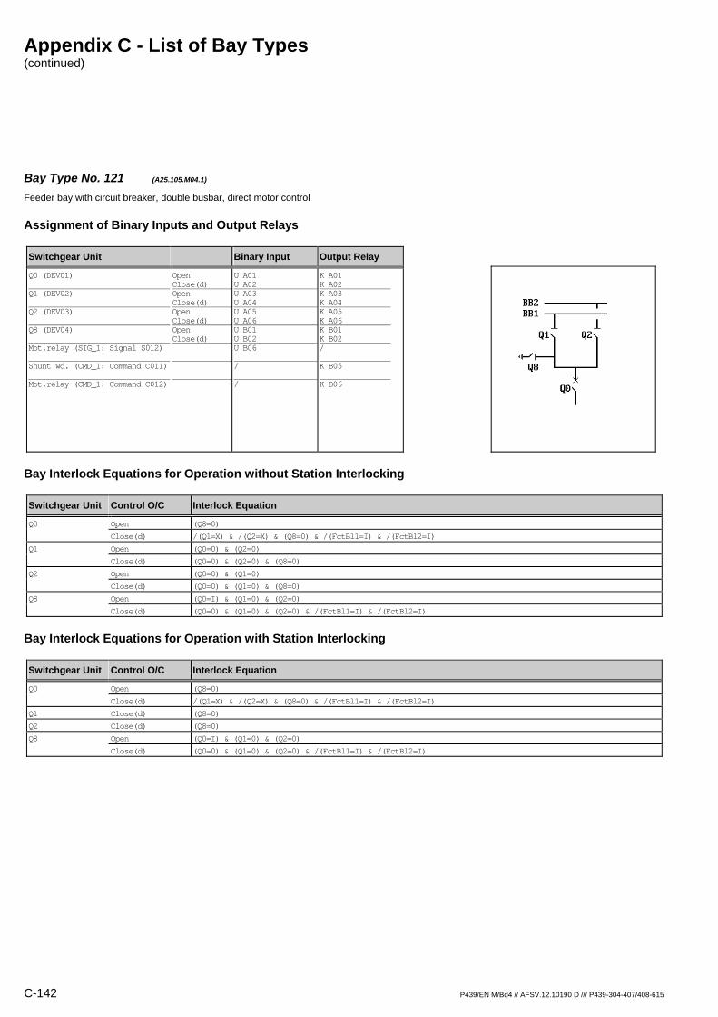
Appendix C - List of Bay Types (continued)
C-142 P439/EN M/Bd4 // AFSV.12.10190 D /// P439-304-407/408-615
Bay Type No. 121 (A25.105.M04.1) Feeder bay with circuit breaker, double busbar, direct motor control
Assignment of Binary Inputs and Output Relays
Switchgear Unit Binary Input Output Relay
Q0 (DEV01) Q1 (DEV02) Q2 (DEV03) Q8 (DEV04) Mot.relay (SIG_1: Signal S012) Shunt wd. (CMD_1: Command C011) Mot.relay (CMD_1: Command C012)
Open Close(d) Open Close(d) Open Close(d) Open Close(d)
U A01 U A02 U A03 U A04 U A05 U A06 U B01 U B02 U B06 / /
K A01 K A02 K A03 K A04 K A05 K A06 K B01 K B02 / K B05 K B06
Bay Interlock Equations for Operation without Station Interlocking
Switchgear Unit Control O/C Interlock Equation
Q0 Open (Q8=0)
Close(d) /(Q1=X) & /(Q2=X) & (Q8=0) & /(FctBl1=I) & /(FctBl2=I)
Q1 Open (Q0=0) & (Q2=0)
Close(d) (Q0=0) & (Q2=0) & (Q8=0)
Q2 Open (Q0=0) & (Q1=0)
Close(d) (Q0=0) & (Q1=0) & (Q8=0)
Q8 Open (Q0=I) & (Q1=0) & (Q2=0)
Close(d) (Q0=0) & (Q1=0) & (Q2=0) & /(FctBl1=I) & /(FctBl2=I)
Bay Interlock Equations for Operation with Station Interlocking
Switchgear Unit Control O/C Interlock Equation
Q0 Open (Q8=0)
Close(d) /(Q1=X) & /(Q2=X) & (Q8=0) & /(FctBl1=I) & /(FctBl2=I)
Q1 Close(d) (Q8=0)
Q2 Close(d) (Q8=0)
Q8 Open (Q0=I) & (Q1=0) & (Q2=0)
Close(d) (Q0=0) & (Q1=0) & (Q2=0) & /(FctBl1=I) & /(FctBl2=I)
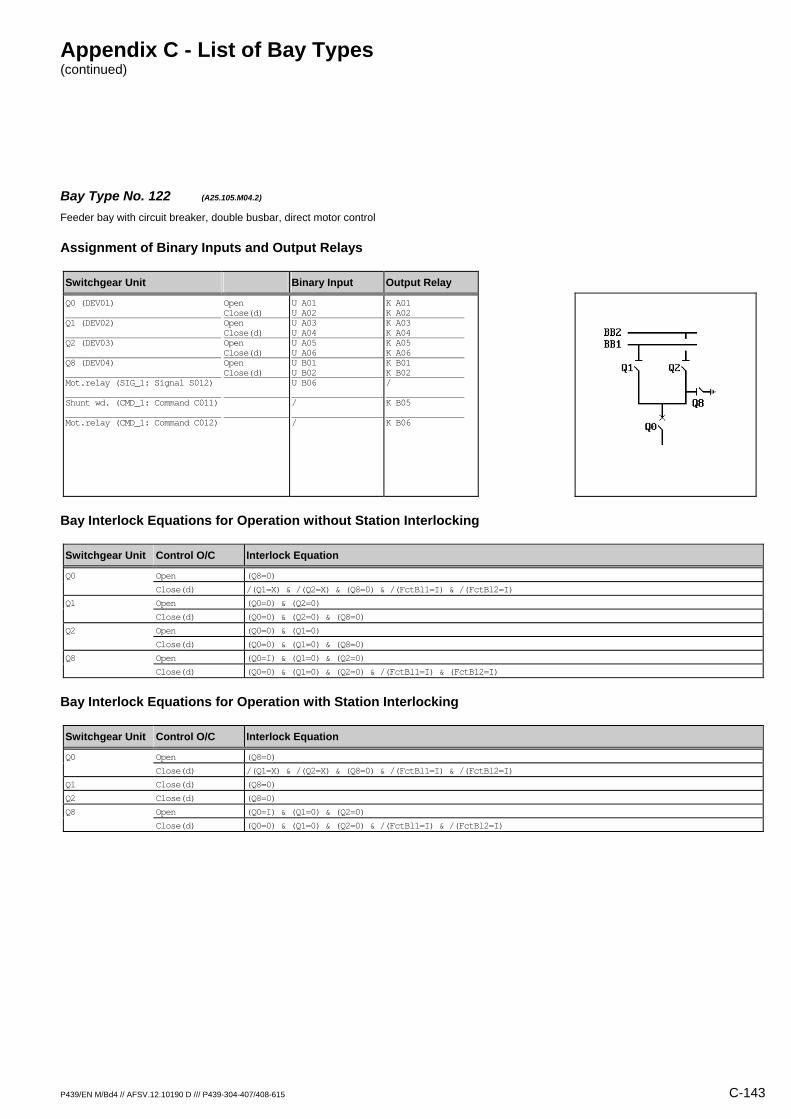
Appendix C - List of Bay Types (continued)
P439/EN M/Bd4 // AFSV.12.10190 D /// P439-304-407/408-615 C-143
Bay Type No. 122 (A25.105.M04.2) Feeder bay with circuit breaker, double busbar, direct motor control
Assignment of Binary Inputs and Output Relays
Switchgear Unit Binary Input Output Relay
Q0 (DEV01) Q1 (DEV02) Q2 (DEV03) Q8 (DEV04) Mot.relay (SIG_1: Signal S012) Shunt wd. (CMD_1: Command C011) Mot.relay (CMD_1: Command C012)
Open Close(d) Open Close(d) Open Close(d) Open Close(d)
U A01 U A02 U A03 U A04 U A05 U A06 U B01 U B02 U B06 / /
K A01 K A02 K A03 K A04 K A05 K A06 K B01 K B02 / K B05 K B06
Bay Interlock Equations for Operation without Station Interlocking
Switchgear Unit Control O/C Interlock Equation
Q0 Open (Q8=0)
Close(d) /(Q1=X) & /(Q2=X) & (Q8=0) & /(FctBl1=I) & /(FctBl2=I)
Q1 Open (Q0=0) & (Q2=0)
Close(d) (Q0=0) & (Q2=0) & (Q8=0)
Q2 Open (Q0=0) & (Q1=0)
Close(d) (Q0=0) & (Q1=0) & (Q8=0)
Q8 Open (Q0=I) & (Q1=0) & (Q2=0)
Close(d) (Q0=0) & (Q1=0) & (Q2=0) & /(FctBl1=I) & (FctBl2=I)
Bay Interlock Equations for Operation with Station Interlocking
Switchgear Unit Control O/C Interlock Equation
Q0 Open (Q8=0)
Close(d) /(Q1=X) & /(Q2=X) & (Q8=0) & /(FctBl1=I) & /(FctBl2=I)
Q1 Close(d) (Q8=0)
Q2 Close(d) (Q8=0)
Q8 Open (Q0=I) & (Q1=0) & (Q2=0)
Close(d) (Q0=0) & (Q1=0) & (Q2=0) & /(FctBl1=I) & /(FctBl2=I)

Appendix C - List of Bay Types (continued)
C-144 P439/EN M/Bd4 // AFSV.12.10190 D /// P439-304-407/408-615
Bay Type No. 123 (A25.105.R01.1) Feeder bay with circuit breaker, double busbar
Assignment of Binary Inputs and Output Relays
Switchgear Unit Binary Input Output Relay
Q0 (DEV01) Q1 (DEV02) Q2 (DEV03) Q8 (DEV04)
Open Close(d) Open Close(d) Open Close(d) Open Close(d)
U A01 U A02 U A03 U A04 U A05 U A06 U B01 U B02
K A01 K A02 / / / / / /
Bay Interlock Equations for Operation without Station Interlocking
Switchgear Unit Control O/C Interlock Equation
Q0 Open (Q8=0)
Close(d) /(Q1=X) & /(Q2=X) & (Q8=0) & /(FctBl1=I) & /(FctBl2=I)
Bay Interlock Equations for Operation with Station Interlocking
Switchgear Unit Control O/C Interlock Equation
Q0 Open (Q8=0)
Close(d) /(Q1=X) & /(Q2=X) & (Q8=0) & /(FctBl1=I) & /(FctBl2=I)

Appendix C - List of Bay Types (continued)
P439/EN M/Bd4 // AFSV.12.10190 D /// P439-304-407/408-615 C-145
Bay Type No. 124 (A25.105.R01.2) Feeder bay with circuit breaker, double busbar
Assignment of Binary Inputs and Output Relays
Switchgear Unit Binary Input Output Relay
Q0 (DEV01) Q1 (DEV02) Q2 (DEV03) Q8 (DEV04)
Open Close(d) Open Close(d) Open Close(d) Open Close(d)
U A01 U A02 U A03 U A04 U A05 U A06 U B01 U B02
K A01 K A02 / / / / / /
Bay Interlock Equations for Operation without Station Interlocking
Switchgear Unit Control O/C Interlock Equation
Q0 Open (Q8=0)
Close(d) /(Q1=X) & /(Q2=X) & (Q8=0) & /(FctBl1=I) & /(FctBl2=I)
Bay Interlock Equations for Operation with Station Interlocking
Switchgear Unit Control O/C Interlock Equation
Q0 Open (Q8=0)
Close(d) /(Q1=X) & /(Q2=X) & (Q8=0) & /(FctBl1=I) & /(FctBl2=I)
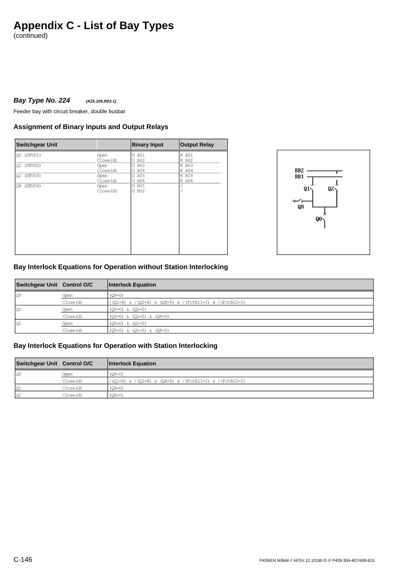
Appendix C - List of Bay Types (continued)
C-146 P439/EN M/Bd4 // AFSV.12.10190 D /// P439-304-407/408-615
Bay Type No. 224 (A25.105.R03.1) Feeder bay with circuit breaker, double busbar
Assignment of Binary Inputs and Output Relays
Switchgear Unit Binary Input Output Relay
Q0 (DEV01) Q1 (DEV02) Q2 (DEV03) Q8 (DEV04)
Open Close(d) Open Close(d) Open Close(d) Open Close(d)
U A01 U A02 U A03 U A04 U A05 U A06 U B01 U B02
K A01 K A02 K A03 K A04 K A05 K A06 / /
Bay Interlock Equations for Operation without Station Interlocking
Switchgear Unit Control O/C Interlock Equation
Q0 Open (Q8=0)
Close(d) /(Q1=X) & /(Q2=X) & (Q8=0) & /(FctBl1=I) & /(FctBl2=I)
Q1 Open (Q0=0) & (Q2=0)
Close(d) (Q0=0) & (Q2=0) & (Q8=0)
Q2 Open (Q0=0) & (Q1=0)
Close(d) (Q0=0) & (Q1=0) & (Q8=0)
Bay Interlock Equations for Operation with Station Interlocking
Switchgear Unit Control O/C Interlock Equation
Q0 Open (Q8=0)
Close(d) /(Q1=X) & /(Q2=X) & (Q8=0) & /(FctBl1=I) & /(FctBl2=I)
Q1 Close(d) (Q8=0)
Q2 Close(d) (Q8=0)

Appendix C - List of Bay Types (continued)
P439/EN M/Bd4 // AFSV.12.10190 D /// P439-304-407/408-615 C-147
Bay Type No. 225 (A25.105.R03.2) Feeder bay with circuit breaker, double busbar
Assignment of Binary Inputs and Output Relays
Switchgear Unit Binary Input Output Relay
Q0 (DEV01) Q1 (DEV02) Q2 (DEV03) Q8 (DEV04)
Open Close(d) Open Close(d) Open Close(d) Open Close(d)
U A01 U A02 U A03 U A04 U A05 U A06 U B01 U B02
K A01 K A02 K A03 K A04 K A05 K A06 / /
Bay Interlock Equations for Operation without Station Interlocking
Switchgear Unit Control O/C Interlock Equation
Q0 Open (Q8=0)
Close(d) /(Q1=X) & /(Q2=X) & (Q8=0) & /(FctBl1=I) & /(FctBl2=I)
Q1 Open (Q0=0) & (Q2=0)
Close(d) (Q0=0) & (Q2=0) & (Q8=0)
Q2 Open (Q0=0) & (Q1=0)
Close(d) (Q0=0) & (Q1=0) & (Q8=0)
Bay Interlock Equations for Operation with Station Interlocking
Switchgear Unit Control O/C Interlock Equation
Q0 Open (Q8=0)
Close(d) /(Q1=X) & /(Q2=X) & (Q8=0) & /(FctBl1=I) & /(FctBl2=I)
Q1 Close(d) (Q8=0)
Q2 Close(d) (Q8=0)

Appendix C - List of Bay Types (continued)
C-148 P439/EN M/Bd4 // AFSV.12.10190 D /// P439-304-407/408-615
Bay Type No. 125 (A25.105.R04.1) Feeder bay with circuit breaker, double busbar
Assignment of Binary Inputs and Output Relays
Switchgear Unit Binary Input Output Relay
Q0 (DEV01) Q1 (DEV02) Q2 (DEV03) Q8 (DEV04)
Open Close(d) Open Close(d) Open Close(d) Open Close(d)
U A01 U A02 U A03 U A04 U A05 U A06 U B01 U B02
K A01 K A02 K A03 K A04 K A05 K A06 K B01 K B02
Bay Interlock Equations for Operation without Station Interlocking
Switchgear Unit Control O/C Interlock Equation
Q0 Open (Q8=0)
Close(d) /(Q1=X) & /(Q2=X) & (Q8=0) & /(FctBl1=I) & /(FctBl2=I)
Q1 Open (Q0=0) & (Q2=0)
Close(d) (Q0=0) & (Q2=0) & (Q8=0)
Q2 Open (Q0=0) & (Q1=0)
Close(d) (Q0=0) & (Q1=0) & (Q8=0)
Q8 Open (Q0=I) & (Q1=0) & (Q2=0)
Close(d) (Q0=0) & (Q1=0) & (Q2=0) & /(FctBl1=I) & /(FctBl2=I)
Bay Interlock Equations for Operation with Station Interlocking
Switchgear Unit Control O/C Interlock Equation
Q0 Open (Q8=0)
Close(d) /(Q1=X) & /(Q2=X) & (Q8=0) & /(FctBl1=I) & /(FctBl2=I)
Q1 Close(d) (Q8=0)
Q2 Close(d) (Q8=0)
Q8 Open (Q0=I) & (Q1=0) & (Q2=0)
Close(d) (Q0=0) & (Q1=0) & (Q2=0) & /(FctBl1=I) & /(FctBl2=I)
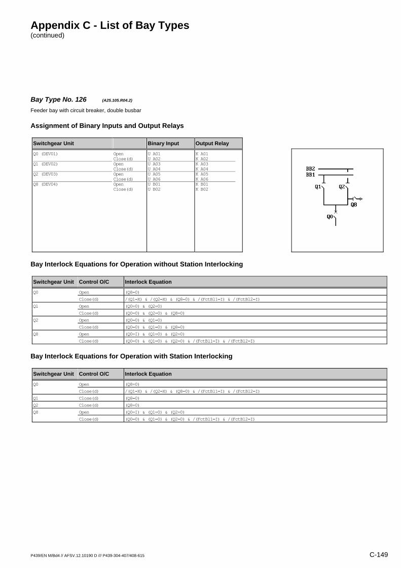
Appendix C - List of Bay Types (continued)
P439/EN M/Bd4 // AFSV.12.10190 D /// P439-304-407/408-615 C-149
Bay Type No. 126 (A25.105.R04.2) Feeder bay with circuit breaker, double busbar
Assignment of Binary Inputs and Output Relays
Switchgear Unit Binary Input Output Relay
Q0 (DEV01) Q1 (DEV02) Q2 (DEV03) Q8 (DEV04)
Open Close(d) Open Close(d) Open Close(d) Open Close(d)
U A01 U A02 U A03 U A04 U A05 U A06 U B01 U B02
K A01 K A02 K A03 K A04 K A05 K A06 K B01 K B02
Bay Interlock Equations for Operation without Station Interlocking
Switchgear Unit Control O/C Interlock Equation
Q0 Open (Q8=0)
Close(d) /(Q1=X) & /(Q2=X) & (Q8=0) & /(FctBl1=I) & /(FctBl2=I)
Q1 Open (Q0=0) & (Q2=0)
Close(d) (Q0=0) & (Q2=0) & (Q8=0)
Q2 Open (Q0=0) & (Q1=0)
Close(d) (Q0=0) & (Q1=0) & (Q8=0)
Q8 Open (Q0=I) & (Q1=0) & (Q2=0)
Close(d) (Q0=0) & (Q1=0) & (Q2=0) & /(FctBl1=I) & /(FctBl2=I)
Bay Interlock Equations for Operation with Station Interlocking
Switchgear Unit Control O/C Interlock Equation
Q0 Open (Q8=0)
Close(d) /(Q1=X) & /(Q2=X) & (Q8=0) & /(FctBl1=I) & /(FctBl2=I)
Q1 Close(d) (Q8=0)
Q2 Close(d) (Q8=0)
Q8 Open (Q0=I) & (Q1=0) & (Q2=0)
Close(d) (Q0=0) & (Q1=0) & (Q2=0) & /(FctBl1=I) & /(FctBl2=I)
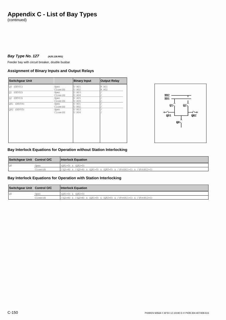
Appendix C - List of Bay Types (continued)
C-150 P439/EN M/Bd4 // AFSV.12.10190 D /// P439-304-407/408-615
Bay Type No. 127 (A25.128.R01) Feeder bay with circuit breaker, double busbar
Assignment of Binary Inputs and Output Relays
Switchgear Unit Binary Input Output Relay
Q0 (DEV01) Q1 (DEV02) Q2 (DEV03) Q81 (DEV04) Q82 (DEV05)
Open Close(d) Open Close(d) Open Close(d) Open Close(d) Open Close(d)
U A01 U A02 U A03 U A04 U A05 U A06 U B01 U B02 U B03 U B04
K A01 K A02 / / / / / / / /
Bay Interlock Equations for Operation without Station Interlocking
Switchgear Unit Control O/C Interlock Equation
Q0 Open (Q81=0) & (Q82=0)
Close(d) /(Q1=X) & /(Q2=X) & (Q81=0) & (Q82=0) & /(FctBl1=I) & /(FctBl2=I)
Bay Interlock Equations for Operation with Station Interlocking
Switchgear Unit Control O/C Interlock Equation
Q0 Open (Q81=0) & (Q82=0)
Close(d) /(Q1=X) & /(Q2=X) & (Q81=0) & (Q82=0) & /(FctBl1=I) & /(FctBl2=I)
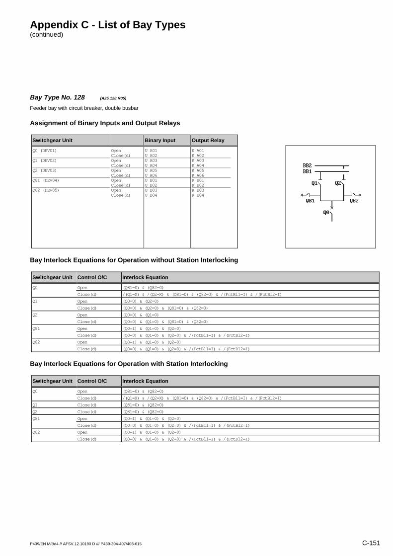
Appendix C - List of Bay Types (continued)
P439/EN M/Bd4 // AFSV.12.10190 D /// P439-304-407/408-615 C-151
Bay Type No. 128 (A25.128.R05) Feeder bay with circuit breaker, double busbar
Assignment of Binary Inputs and Output Relays
Switchgear Unit Binary Input Output Relay
Q0 (DEV01) Q1 (DEV02) Q2 (DEV03) Q81 (DEV04) Q82 (DEV05)
Open Close(d) Open Close(d) Open Close(d) Open Close(d) Open Close(d)
U A01 U A02 U A03 U A04 U A05 U A06 U B01 U B02 U B03 U B04
K A01 K A02 K A03 K A04 K A05 K A06 K B01 K B02 K B03 K B04
Bay Interlock Equations for Operation without Station Interlocking
Switchgear Unit Control O/C Interlock Equation
Q0 Open (Q81=0) & (Q82=0)
Close(d) /(Q1=X) & /(Q2=X) & (Q81=0) & (Q82=0) & /(FctBl1=I) & /(FctBl2=I)
Q1 Open (Q0=0) & (Q2=0)
Close(d) (Q0=0) & (Q2=0) & (Q81=0) & (Q82=0)
Q2 Open (Q0=0) & (Q1=0)
Close(d) (Q0=0) & (Q1=0) & (Q81=0) & (Q82=0)
Q81 Open (Q0=I) & (Q1=0) & (Q2=0)
Close(d) (Q0=0) & (Q1=0) & (Q2=0) & /(FctBl1=I) & /(FctBl2=I)
Q82 Open (Q0=I) & (Q1=0) & (Q2=0)
Close(d) (Q0=0) & (Q1=0) & (Q2=0) & /(FctBl1=I) & /(FctBl2=I)
Bay Interlock Equations for Operation with Station Interlocking
Switchgear Unit Control O/C Interlock Equation
Q0 Open (Q81=0) & (Q82=0)
Close(d) /(Q1=X) & /(Q2=X) & (Q81=0) & (Q82=0) & /(FctBl1=I) & /(FctBl2=I)
Q1 Close(d) (Q81=0) & (Q82=0)
Q2 Close(d) (Q81=0) & (Q82=0)
Q81 Open (Q0=I) & (Q1=0) & (Q2=0)
Close(d) (Q0=0) & (Q1=0) & (Q2=0) & /(FctBl1=I) & /(FctBl2=I)
Q82 Open (Q0=I) & (Q1=0) & (Q2=0)
Close(d) (Q0=0) & (Q1=0) & (Q2=0) & /(FctBl1=I) & /(FctBl2=I)

Appendix C - List of Bay Types (continued)
C-152 P439/EN M/Bd4 // AFSV.12.10190 D /// P439-304-407/408-615
Bay Type No. 133 (L11.100.R01) Bus sectionalizer bay with circuit breaker, single busbar
Assignment of Binary Inputs and Output Relays
Switchgear Unit Binary Input Output Relay
Q0 (DEV01) X01 (DEV02)
Open Close(d) Open Close(d)
U A01 U A02 U A03 U A04
K A01 K A02 / /
Bay Interlock Equations for Operation without Station Interlocking
Switchgear Unit Control O/C Interlock Equation
Q0 Close(d) /(X01=X) & /(FctBl1=I) & /(FctBl2=I)
Bay Interlock Equations for Operation with Station Interlocking
Switchgear Unit Control O/C Interlock Equation
Q0 Close(d) /(X01=X) & /(FctBl1=I) & /(FctBl2=I)
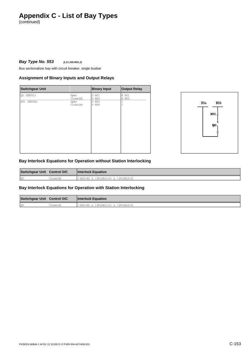
Appendix C - List of Bay Types (continued)
P439/EN M/Bd4 // AFSV.12.10190 D /// P439-304-407/408-615 C-153
Bay Type No. 553 (L11.100.R01.2) Bus sectionalizer bay with circuit breaker, single busbar
Assignment of Binary Inputs and Output Relays
Switchgear Unit Binary Input Output Relay
Q0 (DEV01) X01 (DEV02)
Open Close(d) Open Close(d)
U A01 U A02 U A03 U A04
K A01 K A02 / /
Bay Interlock Equations for Operation without Station Interlocking
Switchgear Unit Control O/C Interlock Equation
Q0 Close(d) /(X01=X) & /(FctBl1=I) & /(FctBl2=I)
Bay Interlock Equations for Operation with Station Interlocking
Switchgear Unit Control O/C Interlock Equation
Q0 Close(d) /(X01=X) & /(FctBl1=I) & /(FctBl2=I)

Appendix C - List of Bay Types (continued)
C-154 P439/EN M/Bd4 // AFSV.12.10190 D /// P439-304-407/408-615
Bay Type No. 134 (L11.100.R02) Bus sectionalizer bay with circuit breaker, single busbar
Assignment of Binary Inputs and Output Relays
Switchgear Unit Binary Input Output Relay
Q0 (DEV01) X01 (DEV02)
Open Close(d) Open Close(d)
U A01 U A02 U A03 U A04
K A01 K A02 K A03 K A04
Bay Interlock Equations for Operation without Station Interlocking
Switchgear Unit Control O/C Interlock Equation
Q0 Close(d) /(X01=X) & /(FctBl1=I) & /(FctBl2=I)
X01 Open (Q0=0)
Close(d) (Q0=0)
Bay Interlock Equations for Operation with Station Interlocking
Switchgear Unit Control O/C Interlock Equation
Q0 Close(d) /(X01=X) & /(FctBl1=I) & /(FctBl2=I)
X01 Open (Q0=0)
Close(d) (Q0=0)

Appendix C - List of Bay Types (continued)
P439/EN M/Bd4 // AFSV.12.10190 D /// P439-304-407/408-615 C-155
Bay Type No. 528 (L11.102.R01) Bus sectionalizer bay with circuit breaker, single busbar
Assignment of Binary Inputs and Output Relays
Switchgear Unit Binary Input Output Relay
Q0 (DEV01) X0 (DEV02) Q15 (DEV03)
Open Close(d) Open Close(d) Open Close(d)
U A01 U A02 U A03 U A04 U A05 U A06
K A01 K A02 / / / /
Bay Interlock Equations for Operation without Station Interlocking
Switchgear Unit Control O/C Interlock Equation
Q0 Close(d) /(X0=X) & (Q15=0) & /(FctBl1=I) & /(FctBl2=I)
Bay Interlock Equations for Operation with Station Interlocking
Switchgear Unit Control O/C Interlock Equation
Q0 Close(d) /(X0=X) & (Q15=0) & /(FctBl1=I) & /(FctBl2=I)
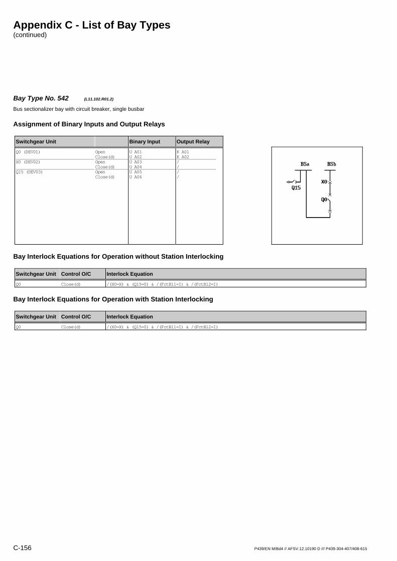
Appendix C - List of Bay Types (continued)
C-156 P439/EN M/Bd4 // AFSV.12.10190 D /// P439-304-407/408-615
Bay Type No. 542 (L11.102.R01.2) Bus sectionalizer bay with circuit breaker, single busbar
Assignment of Binary Inputs and Output Relays
Switchgear Unit Binary Input Output Relay
Q0 (DEV01) X0 (DEV02) Q15 (DEV03)
Open Close(d) Open Close(d) Open Close(d)
U A01 U A02 U A03 U A04 U A05 U A06
K A01 K A02 / / / /
Bay Interlock Equations for Operation without Station Interlocking
Switchgear Unit Control O/C Interlock Equation
Q0 Close(d) /(X0=X) & (Q15=0) & /(FctBl1=I) & /(FctBl2=I)
Bay Interlock Equations for Operation with Station Interlocking
Switchgear Unit Control O/C Interlock Equation
Q0 Close(d) /(X0=X) & (Q15=0) & /(FctBl1=I) & /(FctBl2=I)

Appendix C - List of Bay Types (continued)
P439/EN M/Bd4 // AFSV.12.10190 D /// P439-304-407/408-615 C-157
Bay Type No. 135 (L11.104.R01) Bus sectionalizer bay with circuit breaker, single busbar
Assignment of Binary Inputs and Output Relays
Switchgear Unit Binary Input Output Relay
Q0 (DEV01) X01 (DEV02) Q8 (DEV03)
Open Close(d) Open Close(d) Open Close(d)
U A01 U A02 U A03 U A04 U A05 U A06
K A01 K A02 / / / /
Bay Interlock Equations for Operation without Station Interlocking
Switchgear Unit Control O/C Interlock Equation
Q0 Close(d) /(X01=X) & /(FctBl1=I) & /(FctBl2=I)
Bay Interlock Equations for Operation with Station Interlocking
Switchgear Unit Control O/C Interlock Equation
Q0 Close(d) /(X01=X) & /(FctBl1=I) & /(FctBl2=I)

Appendix C - List of Bay Types (continued)
C-158 P439/EN M/Bd4 // AFSV.12.10190 D /// P439-304-407/408-615
Bay Type No. 136 (L11.104.R02) Bus sectionalizer bay with circuit breaker, single busbar
Assignment of Binary Inputs and Output Relays
Switchgear Unit Binary Input Output Relay
Q0 (DEV01) X01 (DEV02) Q8 (DEV03)
Open Close(d) Open Close(d) Open Close(d)
U A01 U A02 U A03 U A04 U A05 U A06
K A01 K A02 K A03 K A04 / /
Bay Interlock Equations for Operation without Station Interlocking
Switchgear Unit Control O/C Interlock Equation
Q0 Close(d) /(X01=X) & /(FctBl1=I) & /(FctBl2=I)
X01 Open (Q0=0)
Close(d) (Q0=0) & (Q8=0)
Bay Interlock Equations for Operation with Station Interlocking
Switchgear Unit Control O/C Interlock Equation
Q0 Close(d) /(X01=X) & /(FctBl1=I) & /(FctBl2=I)
X01 Open (Q0=0)
Close(d) (Q0=0) & (Q8=0)

Appendix C - List of Bay Types (continued)
P439/EN M/Bd4 // AFSV.12.10190 D /// P439-304-407/408-615 C-159
Bay Type No. 137 (L11.104.R03) Bus sectionalizer bay with circuit breaker, single busbar
Assignment of Binary Inputs and Output Relays
Switchgear Unit Binary Input Output Relay
Q0 (DEV01) X01 (DEV02) Q8 (DEV03)
Open Close(d) Open Close(d) Open Close(d)
U A01 U A02 U A03 U A04 U A05 U A06
K A01 K A02 K A03 K A04 K A05 K A06
Bay Interlock Equations for Operation without Station Interlocking
Switchgear Unit Control O/C Interlock Equation
Q0 Close(d) /(X01=X) & /(FctBl1=I) & /(FctBl2=I)
Q8 Close(d) (X01=0) & (Q8=I)
X01 Open (Q0=0)
Close(d) (Q0=0) & (Q8=0)
Bay Interlock Equations for Operation with Station Interlocking
Switchgear Unit Control O/C Interlock Equation
Q0 Close(d) /(X01=X) & /(FctBl1=I) & /(FctBl2=I)
Q8 Close(d) (X01=0)
X01 Open (Q0=0)
Close(d) (Q0=0) & (Q8=0)

Appendix C - List of Bay Types (continued)
C-160 P439/EN M/Bd4 // AFSV.12.10190 D /// P439-304-407/408-615
Bay Type No. 547 (L11.112.M04) Bus sectionalizer bay with circuit breaker, single busbar, direct motor control
Assignment of Binary Inputs and Output Relays
Switchgear Unit Binary Input Output Relay
Q0 (DEV01) X0 (DEV02) Q15 (DEV03) Q16 (DEV04) Mot.relay (SIG_1: Signal S012) Shunt wd. (CMD_1: Command C011) Mot.relay (CMD_1: Command C012)
Open Close(d) Open Close(d) Open Close(d) Open Close(d)
U A01 U A02 U A03 U A04 U A05 U A06 U B01 U B02 U B06 / /
K A01 K A02 K A03 K A04 K A05 K A06 K B01 K B02 / K B05 K B06
Bay Interlock Equations for Operation without Station Interlocking
Switchgear Unit Control O/C Interlock Equation
Q0 Close(d) /(X0=X) & (Q15=0) & (Q16=0) & /(FctBl1=I) & /(FctBl2=I)
Q15 Close(d) (Q15=I)
Q16 Close(d) (Q16=I)
X0 Open (Q0=0)
Close(d) (Q0=0) & (Q15=0) & (Q16=0)
Bay Interlock Equations for Operation with Station Interlocking
Switchgear Unit Control O/C Interlock Equation
Q0 Close(d) /(X0=X) & (Q15=0) & (Q16=0) & /(FctBl1=I) & /(FctBl2=I)
X0 Open (Q0=0)
Close(d) (Q0=0) & (Q15=0) & (Q16=0)

Appendix C - List of Bay Types (continued)
P439/EN M/Bd4 // AFSV.12.10190 D /// P439-304-407/408-615 C-161
Bay Type No. 564 (L11.112.R01.2) Bus sectionalizer bay with circuit breaker, single busbar
Assignment of Binary Inputs and Output Relays
Switchgear Unit Binary Input Output Relay
Q0 (DEV01) X01 (DEV02) Q15 (DEV03) Q16 (DEV04)
Open Close(d) Open Close(d) Open Close(d) Open Close(d)
U A01 U A02 U A03 U A04 U A05 U A06 U B01 U B02
K A01 K A02 / / / / / /
Bay Interlock Equations for Operation without Station Interlocking
Switchgear Unit Control O/C Interlock Equation
Q0 Close(d) /(X01=X) & (Q15=0) & (Q16=0) & /(FctBl1=I) & /(FctBl2=I)
Bay Interlock Equations for Operation with Station Interlocking
Switchgear Unit Control O/C Interlock Equation
Q0 Close(d) /(X01=X) & /(FctBl1=I) & /(FctBl2=I)

Appendix C - List of Bay Types (continued)
C-162 P439/EN M/Bd4 // AFSV.12.10190 D /// P439-304-407/408-615
Bay Type No. 138 (L11.116.R01) Bus sectionalizer bay with circuit breaker, single busbar
Assignment of Binary Inputs and Output Relays
Switchgear Unit Binary Input Output Relay
Q0 (DEV01) X01 (DEV02) X02 (DEV03)
Open Close(d) Open Close(d) Open Close(d)
U A01 U A02 U A03 U A04 U A05 U A06
K A01 K A02 / / / /
Bay Interlock Equations for Operation without Station Interlocking
Switchgear Unit Control O/C Interlock Equation
Q0 Close(d) /(X01=X) & /(X02=X) & /(FctBl1=I) & /(FctBl2=I)
Bay Interlock Equations for Operation with Station Interlocking
Switchgear Unit Control O/C Interlock Equation
Q0 Close(d) /(X01=X) & /(X02=X) & /(FctBl1=I) & /(FctBl2=I)

Appendix C - List of Bay Types (continued)
P439/EN M/Bd4 // AFSV.12.10190 D /// P439-304-407/408-615 C-163
Bay Type No. 545 (L11.116.R01.2) Bus sectionalizer bay with circuit breaker, single busbar
Assignment of Binary Inputs and Output Relays
Switchgear Unit Binary Input Output Relay
Q0 (DEV01) X01 (DEV02) X02 (DEV03)
Open Close(d) Open Close(d) Open Close(d)
U A01 U A02 U A03 U A04 U A05 U A06
K A01 K A02 / / / /
Bay Interlock Equations for Operation without Station Interlocking
Switchgear Unit Control O/C Interlock Equation
Q0 Close(d) /(X01=X) & /(X02=X) & /(FctBl1=I) & /(FctBl2=I)
Bay Interlock Equations for Operation with Station Interlocking
Switchgear Unit Control O/C Interlock Equation
Q0 Close(d) /(X01=X) & /(X02=X) & /(FctBl1=I) & /(FctBl2=I)

Appendix C - List of Bay Types (continued)
C-164 P439/EN M/Bd4 // AFSV.12.10190 D /// P439-304-407/408-615
Bay Type No. 139 (L11.116.R03) Bus sectionalizer bay with circuit breaker, single busbar
Assignment of Binary Inputs and Output Relays
Switchgear Unit Binary Input Output Relay
Q0 (DEV01) X01 (DEV02) X02 (DEV03)
Open Close(d) Open Close(d) Open Close(d)
U A01 U A02 U A03 U A04 U A05 U A06
K A01 K A02 K A03 K A04 K A05 K A06
Bay Interlock Equations for Operation without Station Interlocking
Switchgear Unit Control O/C Interlock Equation
Q0 Close(d) /(X01=X) & /(X02=X) & /(FctBl1=I) & /(FctBl2=I)
X01 Open (Q0=0)
Close(d) (Q0=0)
X02 Open (Q0=0)
Close(d) (Q0=0)
Bay Interlock Equations for Operation with Station Interlocking
Switchgear Unit Control O/C Interlock Equation
Q0 Close(d) /(X01=X) & /(X02=X) & /(FctBl1=I) & /(FctBl2=I)
X01 Open (Q0=0)
Close(d) (Q0=0)
X02 Open (Q0=0)
Close(d) (Q0=0)
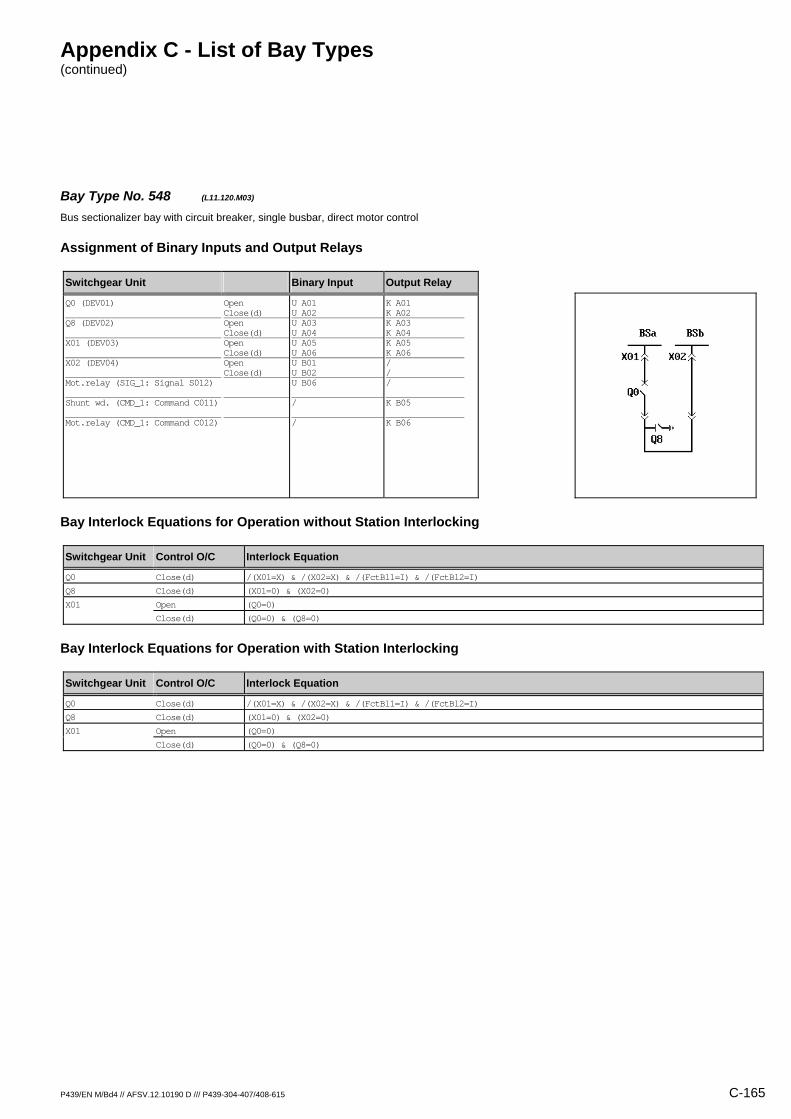
Appendix C - List of Bay Types (continued)
P439/EN M/Bd4 // AFSV.12.10190 D /// P439-304-407/408-615 C-165
Bay Type No. 548 (L11.120.M03) Bus sectionalizer bay with circuit breaker, single busbar, direct motor control
Assignment of Binary Inputs and Output Relays
Switchgear Unit Binary Input Output Relay
Q0 (DEV01) Q8 (DEV02) X01 (DEV03) X02 (DEV04) Mot.relay (SIG_1: Signal S012) Shunt wd. (CMD_1: Command C011) Mot.relay (CMD_1: Command C012)
Open Close(d) Open Close(d) Open Close(d) Open Close(d)
U A01 U A02 U A03 U A04 U A05 U A06 U B01 U B02 U B06 / /
K A01 K A02 K A03 K A04 K A05 K A06 / / / K B05 K B06
Bay Interlock Equations for Operation without Station Interlocking
Switchgear Unit Control O/C Interlock Equation
Q0 Close(d) /(X01=X) & /(X02=X) & /(FctBl1=I) & /(FctBl2=I)
Q8 Close(d) (X01=0) & (X02=0)
X01 Open (Q0=0)
Close(d) (Q0=0) & (Q8=0)
Bay Interlock Equations for Operation with Station Interlocking
Switchgear Unit Control O/C Interlock Equation
Q0 Close(d) /(X01=X) & /(X02=X) & /(FctBl1=I) & /(FctBl2=I)
Q8 Close(d) (X01=0) & (X02=0)
X01 Open (Q0=0)
Close(d) (Q0=0) & (Q8=0)
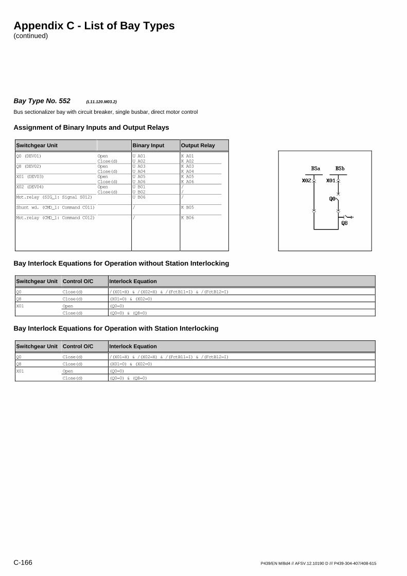
Appendix C - List of Bay Types (continued)
C-166 P439/EN M/Bd4 // AFSV.12.10190 D /// P439-304-407/408-615
Bay Type No. 552 (L11.120.M03.2) Bus sectionalizer bay with circuit breaker, single busbar, direct motor control
Assignment of Binary Inputs and Output Relays
Switchgear Unit Binary Input Output Relay
Q0 (DEV01) Q8 (DEV02) X01 (DEV03) X02 (DEV04) Mot.relay (SIG_1: Signal S012) Shunt wd. (CMD_1: Command C011) Mot.relay (CMD_1: Command C012)
Open Close(d) Open Close(d) Open Close(d) Open Close(d)
U A01 U A02 U A03 U A04 U A05 U A06 U B01 U B02 U B06 / /
K A01 K A02 K A03 K A04 K A05 K A06 / / / K B05 K B06
Bay Interlock Equations for Operation without Station Interlocking
Switchgear Unit Control O/C Interlock Equation
Q0 Close(d) /(X01=X) & /(X02=X) & /(FctBl1=I) & /(FctBl2=I)
Q8 Close(d) (X01=0) & (X02=0)
X01 Open (Q0=0)
Close(d) (Q0=0) & (Q8=0)
Bay Interlock Equations for Operation with Station Interlocking
Switchgear Unit Control O/C Interlock Equation
Q0 Close(d) /(X01=X) & /(X02=X) & /(FctBl1=I) & /(FctBl2=I)
Q8 Close(d) (X01=0) & (X02=0)
X01 Open (Q0=0)
Close(d) (Q0=0) & (Q8=0)

Appendix C - List of Bay Types (continued)
P439/EN M/Bd4 // AFSV.12.10190 D /// P439-304-407/408-615 C-167
Bay Type No. 140 (L11.120.R01) Bus sectionalizer bay with circuit breaker, single busbar
Assignment of Binary Inputs and Output Relays
Switchgear Unit Binary Input Output Relay
Q0 (DEV01) X01 (DEV02) X02 (DEV03) Q8 (DEV04)
Open Close(d) Open Close(d) Open Close(d) Open Close(d)
U A01 U A02 U A03 U A04 U A05 U A06 U B01 U B02
K A01 K A02 / / / / / /
Bay Interlock Equations for Operation without Station Interlocking
Switchgear Unit Control O/C Interlock Equation
Q0 Close(d) /(X01=X) & /(X02=X) & /(FctBl1=I) & /(FctBl2=I)
Bay Interlock Equations for Operation with Station Interlocking
Switchgear Unit Control O/C Interlock Equation
Q0 Close(d) /(X01=X) & /(X02=X) & /(FctBl1=I) & /(FctBl2=I)

Appendix C - List of Bay Types (continued)
C-168 P439/EN M/Bd4 // AFSV.12.10190 D /// P439-304-407/408-615
Bay Type No. 543 (L11.120.R03) Bus sectionalizer bay with circuit breaker, single busbar
Assignment of Binary Inputs and Output Relays
Switchgear Unit Binary Input Output Relay
Q0 (DEV01) X01 (DEV02) X02 (DEV03) Q8 (DEV04)
Open Close(d) Open Close(d) Open Close(d) Open Close(d)
U A01 U A02 U A03 U A04 U A05 U A06 U B01 U B02
K A01 K A02 K A03 K A04 / / K B01 K B02
Bay Interlock Equations for Operation without Station Interlocking
Switchgear Unit Control O/C Interlock Equation
Q0 Close(d) /(X01=X) & /(X02=X) & /(FctBl1=I) & /(FctBl2=I)
Q8 Close(d) (X01=0) & (X02=0)
X01 Open (Q0=0)
Close(d) (Q0=0) & (Q8=0)
Bay Interlock Equations for Operation with Station Interlocking
Switchgear Unit Control O/C Interlock Equation
Q0 Close(d) /(X01=X) & /(X02=X) & /(FctBl1=I) & /(FctBl2=I)
Q8 Close(d) (X01=0) & (X02=0)
X01 Open (Q0=0)
Close(d) (Q0=0) & (Q8=0)

Appendix C - List of Bay Types (continued)
P439/EN M/Bd4 // AFSV.12.10190 D /// P439-304-407/408-615 C-169
Bay Type No. 141 (L11.120.R03) Bus sectionalizer bay with circuit breaker, single busbar
Assignment of Binary Inputs and Output Relays
Switchgear Unit Binary Input Output Relay
Q0 (DEV01) X01 (DEV02) X02 (DEV03) Q8 (DEV04)
Open Close(d) Open Close(d) Open Close(d) Open Close(d)
U A01 U A02 U A03 U A04 U A05 U A06 U B01 U B02
K A01 K A02 K A03 K A04 K A05 K A06 / /
Bay Interlock Equations for Operation without Station Interlocking
Switchgear Unit Control O/C Interlock Equation
Q0 Close(d) /(X01=X) & /(X02=X) & /(FctBl1=I) & /(FctBl2=I)
X01 Open (Q0=0)
Close(d) (Q0=0) & (Q8=0)
X02 Open (Q0=0)
Close(d) (Q0=0) & (Q8=0)
Bay Interlock Equations for Operation with Station Interlocking
Switchgear Unit Control O/C Interlock Equation
Q0 Close(d) /(X01=X) & /(X02=X) & /(FctBl1=I) & /(FctBl2=I)
X01 Open (Q0=0)
Close(d) (Q0=0) & (Q8=0)
X02 Open (Q0=0)
Close(d) (Q0=0) & (Q8=0)

Appendix C - List of Bay Types (continued)
C-170 P439/EN M/Bd4 // AFSV.12.10190 D /// P439-304-407/408-615
Bay Type No. 142 (L11.120.R04) Bus sectionalizer bay with circuit breaker, single busbar
Assignment of Binary Inputs and Output Relays
Switchgear Unit Binary Input Output Relay
Q0 (DEV01) X01 (DEV02) X02 (DEV03) Q8 (DEV04)
Open Close(d) Open Close(d) Open Close(d) Open Close(d)
U A01 U A02 U A03 U A04 U A05 U A06 U B01 U B02
K A01 K A02 K A03 K A04 K A05 K A06 K B01 K B02
Bay Interlock Equations for Operation without Station Interlocking
Switchgear Unit Control O/C Interlock Equation
Q0 Close(d) /(X01=X) & /(X02=X) & /(FctBl1=I) & /(FctBl2=I)
Q8 Close(d) (X01=0) & (X02=0)
X01 Open (Q0=0)
Close(d) (Q0=0) & (Q8=0)
X02 Open (Q0=0)
Close(d) (Q0=0) & (Q8=0)
Bay Interlock Equations for Operation with Station Interlocking
Switchgear Unit Control O/C Interlock Equation
Q0 Close(d) /(X01=X) & /(X02=X) & /(FctBl1=I) & /(FctBl2=I)
Q8 Close(d) (X01=0) & (X02=0)
X01 Open (Q0=0)
Close(d) (Q0=0) & (Q8=0)
X02 Open (Q0=0)
Close(d) (Q0=0) & (Q8=0)

Appendix C - List of Bay Types (continued)
P439/EN M/Bd4 // AFSV.12.10190 D /// P439-304-407/408-615 C-171
Bay Type No. 558 (L11.128.R01) Bus sectionalizer bay with circuit breaker, single busbar
Assignment of Binary Inputs and Output Relays
Switchgear Unit Binary Input Output Relay
Q0 (DEV01) X01 (DEV02) X02 (DEV03) Q81 (DEV04) Q82 (DEV05)
Open Close(d) Open Close(d) Open Close(d) Open Close(d) Open Close(d)
U A01 U A02 U A03 U A04 U A05 U A06 U B01 U B02 U B03 U B04
K A01 K A02 / / / / / / / /
Bay Interlock Equations for Operation without Station Interlocking
Switchgear Unit Control O/C Interlock Equation
Q0 Close(d) /(X01=X) & /(X02=X) & /(FctBl1=I) & /(FctBl2=I)
Bay Interlock Equations for Operation with Station Interlocking
Switchgear Unit Control O/C Interlock Equation
Q0 Close(d) /(X01=X) & /(X02=X) & /(FctBl1=I) & /(FctBl2=I)
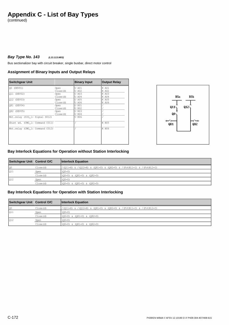
Appendix C - List of Bay Types (continued)
C-172 P439/EN M/Bd4 // AFSV.12.10190 D /// P439-304-407/408-615
Bay Type No. 143 (L13.113.M03) Bus sectionalizer bay with circuit breaker, single busbar, direct motor control
Assignment of Binary Inputs and Output Relays
Switchgear Unit Binary Input Output Relay
Q0 (DEV01) Q11 (DEV02) Q12 (DEV03) Q81 (DEV04) Q82 (DEV05) Mot.relay (SIG_1: Signal S012) Shunt wd. (CMD_1: Command C011) Mot.relay (CMD_1: Command C012)
Open Close(d) Open Close(d) Open Close(d) Open Close(d) Open Close(d)
U A01 U A02 U A03 U A04 U A05 U A06 U B01 U B02 U B03 U B04 U B06 / /
K A01 K A02 K A03 K A04 K A05 K A06 / / / / / K B05 K B06
Bay Interlock Equations for Operation without Station Interlocking
Switchgear Unit Control O/C Interlock Equation
Q0 Close(d) /(Q11=X) & /(Q12=X) & (Q81=0) & (Q82=0) & /(FctBl1=I) & /(FctBl2=I)
Q11 Open (Q0=0)
Close(d) (Q0=0) & (Q81=0) & (Q82=0)
Q12 Open (Q0=0)
Close(d) (Q0=0) & (Q81=0) & (Q82=0)
Bay Interlock Equations for Operation with Station Interlocking
Switchgear Unit Control O/C Interlock Equation
Q0 Close(d) /(Q11=X) & /(Q12=X) & (Q81=0) & (Q82=0) & /(FctBl1=I) & /(FctBl2=I)
Q11 Open (Q0=0)
Close(d) (Q0=0) & (Q81=0) & (Q82=0)
Q12 Open (Q0=0)
Close(d) (Q0=0) & (Q81=0) & (Q82=0)

Appendix C - List of Bay Types (continued)
P439/EN M/Bd4 // AFSV.12.10190 D /// P439-304-407/408-615 C-173
Bay Type No. 144 (L13.113.M05) Bus sectionalizer bay with circuit breaker, single busbar, direct motor control
Assignment of Binary Inputs and Output Relays
Switchgear Unit Binary Input Output Relay
Q0 (DEV01) Q11 (DEV02) Q12 (DEV03) Q81 (DEV04) Q82 (DEV05) Mot.relay (SIG_1: Signal S012) Shunt wd. (CMD_1: Command C011) Mot.relay (CMD_1: Command C012)
Open Close(d) Open Close(d) Open Close(d) Open Close(d) Open Close(d)
U A01 U A02 U A03 U A04 U A05 U A06 U B01 U B02 U B03 U B04 U B06 / /
K A01 K A02 K A03 K A04 K A05 K A06 K B01 K B02 K B03 K B04 / K B05 K B06
Bay Interlock Equations for Operation without Station Interlocking
Switchgear Unit Control O/C Interlock Equation
Q0 Close(d) /(Q11=X) & /(Q12=X) & (Q81=0) & (Q82=0) & /(FctBl1=I) & /(FctBl2=I)
Q11 Open (Q0=0)
Close(d) (Q0=0) & (Q81=0) & (Q82=0)
Q12 Open (Q0=0)
Close(d) (Q0=0) & (Q81=0) & (Q82=0)
Q81 Close(d) (Q0=0) & (Q11=0) & (Q12=0)
Q82 Close(d) (Q0=0) & (Q11=0) & (Q12=0)
Bay Interlock Equations for Operation with Station Interlocking
Switchgear Unit Control O/C Interlock Equation
Q0 Close(d) /(Q11=X) & /(Q12=X) & (Q81=0) & (Q82=0) & /(FctBl1=I) & /(FctBl2=I)
Q11 Open (Q0=0)
Close(d) (Q0=0) & (Q81=0) & (Q82=0)
Q12 Open (Q0=0)
Close(d) (Q0=0) & (Q81=0) & (Q82=0)
Q81 Close(d) (Q0=0) & (Q11=0) & (Q12=0)
Q82 Close(d) (Q0=0) & (Q11=0) & (Q12=0)

Appendix C - List of Bay Types (continued)
C-174 P439/EN M/Bd4 // AFSV.12.10190 D /// P439-304-407/408-615
Bay Type No. 145 (L13.113.R01) Bus sectionalizer bay with circuit breaker, single busbar
Assignment of Binary Inputs and Output Relays
Switchgear Unit Binary Input Output Relay
Q0 (DEV01) Q11 (DEV02) Q12 (DEV03) Q81 (DEV04) Q82 (DEV05)
Open Close(d) Open Close(d) Open Close(d) Open Close(d) Open Close(d)
U A01 U A02 U A03 U A04 U A05 U A06 U B01 U B02 U B03 U B04
K A01 K A02 / / / / / / / /
Bay Interlock Equations for Operation without Station Interlocking
Switchgear Unit Control O/C Interlock Equation
Q0 Close(d) /(Q11=X) & /(Q12=X) & (Q81=0) & (Q82=0) & /(FctBl1=I) & /(FctBl2=I)
Bay Interlock Equations for Operation with Station Interlocking
Switchgear Unit Control O/C Interlock Equation
Q0 Close(d) /(Q11=X) & /(Q12=X) & (Q81=0) & (Q82=0) & /(FctBl1=I) & /(FctBl2=I)
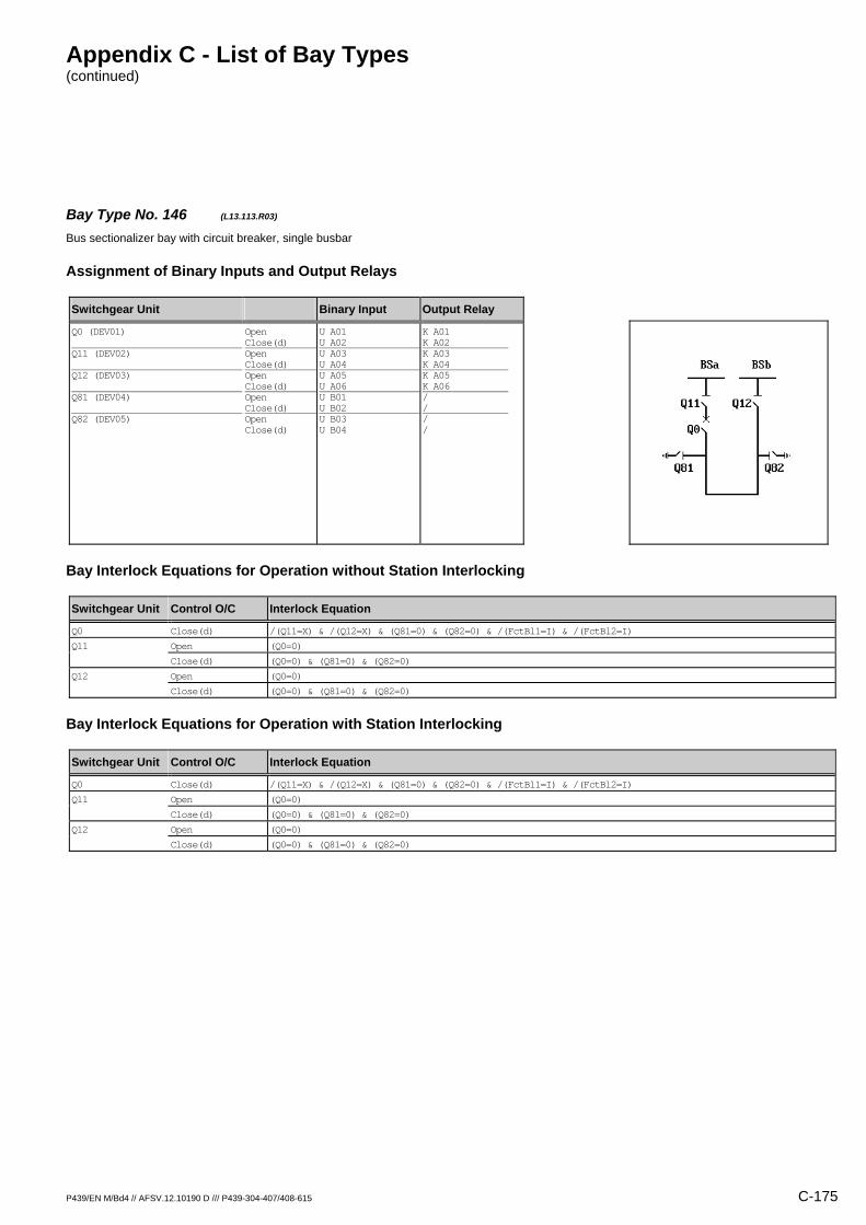
Appendix C - List of Bay Types (continued)
P439/EN M/Bd4 // AFSV.12.10190 D /// P439-304-407/408-615 C-175
Bay Type No. 146 (L13.113.R03) Bus sectionalizer bay with circuit breaker, single busbar
Assignment of Binary Inputs and Output Relays
Switchgear Unit Binary Input Output Relay
Q0 (DEV01) Q11 (DEV02) Q12 (DEV03) Q81 (DEV04) Q82 (DEV05)
Open Close(d) Open Close(d) Open Close(d) Open Close(d) Open Close(d)
U A01 U A02 U A03 U A04 U A05 U A06 U B01 U B02 U B03 U B04
K A01 K A02 K A03 K A04 K A05 K A06 / / / /
Bay Interlock Equations for Operation without Station Interlocking
Switchgear Unit Control O/C Interlock Equation
Q0 Close(d) /(Q11=X) & /(Q12=X) & (Q81=0) & (Q82=0) & /(FctBl1=I) & /(FctBl2=I)
Q11 Open (Q0=0)
Close(d) (Q0=0) & (Q81=0) & (Q82=0)
Q12 Open (Q0=0)
Close(d) (Q0=0) & (Q81=0) & (Q82=0)
Bay Interlock Equations for Operation with Station Interlocking
Switchgear Unit Control O/C Interlock Equation
Q0 Close(d) /(Q11=X) & /(Q12=X) & (Q81=0) & (Q82=0) & /(FctBl1=I) & /(FctBl2=I)
Q11 Open (Q0=0)
Close(d) (Q0=0) & (Q81=0) & (Q82=0)
Q12 Open (Q0=0)
Close(d) (Q0=0) & (Q81=0) & (Q82=0)
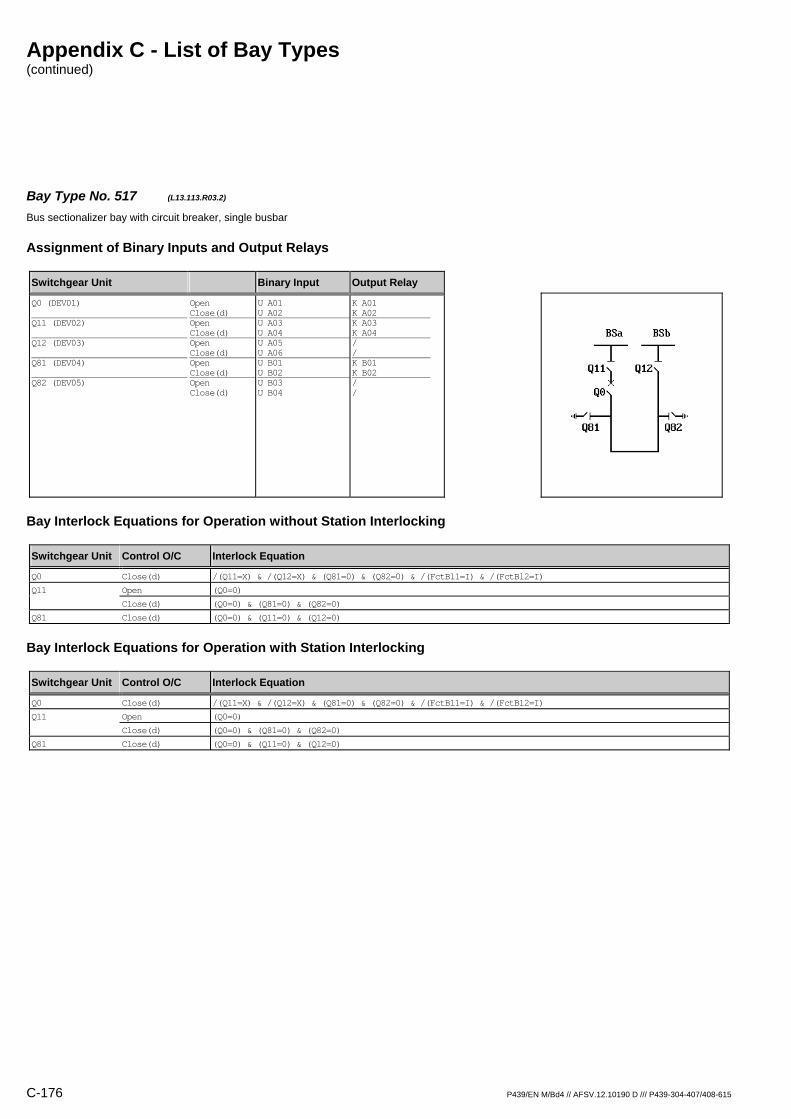
Appendix C - List of Bay Types (continued)
C-176 P439/EN M/Bd4 // AFSV.12.10190 D /// P439-304-407/408-615
Bay Type No. 517 (L13.113.R03.2) Bus sectionalizer bay with circuit breaker, single busbar
Assignment of Binary Inputs and Output Relays
Switchgear Unit Binary Input Output Relay
Q0 (DEV01) Q11 (DEV02) Q12 (DEV03) Q81 (DEV04) Q82 (DEV05)
Open Close(d) Open Close(d) Open Close(d) Open Close(d) Open Close(d)
U A01 U A02 U A03 U A04 U A05 U A06 U B01 U B02 U B03 U B04
K A01 K A02 K A03 K A04 / / K B01 K B02 / /
Bay Interlock Equations for Operation without Station Interlocking
Switchgear Unit Control O/C Interlock Equation
Q0 Close(d) /(Q11=X) & /(Q12=X) & (Q81=0) & (Q82=0) & /(FctBl1=I) & /(FctBl2=I)
Q11 Open (Q0=0)
Close(d) (Q0=0) & (Q81=0) & (Q82=0)
Q81 Close(d) (Q0=0) & (Q11=0) & (Q12=0)
Bay Interlock Equations for Operation with Station Interlocking
Switchgear Unit Control O/C Interlock Equation
Q0 Close(d) /(Q11=X) & /(Q12=X) & (Q81=0) & (Q82=0) & /(FctBl1=I) & /(FctBl2=I)
Q11 Open (Q0=0)
Close(d) (Q0=0) & (Q81=0) & (Q82=0)
Q81 Close(d) (Q0=0) & (Q11=0) & (Q12=0)

Appendix C - List of Bay Types (continued)
P439/EN M/Bd4 // AFSV.12.10190 D /// P439-304-407/408-615 C-177
Bay Type No. 147 (L13.113.R05) Bus sectionalizer bay with circuit breaker, single busbar
Assignment of Binary Inputs and Output Relays
Switchgear Unit Binary Input Output Relay
Q0 (DEV01) Q11 (DEV02) Q12 (DEV03) Q81 (DEV04) Q82 (DEV05)
Open Close(d) Open Close(d) Open Close(d) Open Close(d) Open Close(d)
U A01 U A02 U A03 U A04 U A05 U A06 U B01 U B02 U B03 U B04
K A01 K A02 K A03 K A04 K A05 K A06 K B01 K B02 K B03 K B04
Bay Interlock Equations for Operation without Station Interlocking
Switchgear Unit Control O/C Interlock Equation
Q0 Close(d) /(Q11=X) & /(Q12=X) & (Q81=0) & (Q82=0) & /(FctBl1=I) & /(FctBl2=I)
Q11 Open (Q0=0)
Close(d) (Q0=0) & (Q81=0) & (Q82=0)
Q12 Open (Q0=0)
Close(d) (Q0=0) & (Q81=0) & (Q82=0)
Q81 Close(d) (Q0=0) & (Q11=0) & (Q12=0)
Q82 Close(d) (Q0=0) & (Q11=0) & (Q12=0)
Bay Interlock Equations for Operation with Station Interlocking
Switchgear Unit Control O/C Interlock Equation
Q0 Close(d) /(Q11=X) & /(Q12=X) & (Q81=0) & (Q82=0) & /(FctBl1=I) & /(FctBl2=I)
Q11 Open (Q0=0)
Close(d) (Q0=0) & (Q81=0) & (Q82=0)
Q12 Open (Q0=0)
Close(d) (Q0=0) & (Q81=0) & (Q82=0)
Q81 Close(d) (Q0=0) & (Q11=0) & (Q12=0)
Q82 Close(d) (Q0=0) & (Q11=0) & (Q12=0)
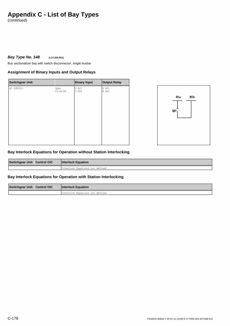
Appendix C - List of Bay Types (continued)
C-178 P439/EN M/Bd4 // AFSV.12.10190 D /// P439-304-407/408-615
Bay Type No. 148 (L13.200.R01) Bus sectionalizer bay with switch disconnector, single busbar
Assignment of Binary Inputs and Output Relays
Switchgear Unit Binary Input Output Relay
Q0 (DEV01)
Open Close(d)
U A01 U A02
K A01 K A02
Bay Interlock Equations for Operation without Station Interlocking
Switchgear Unit Control O/C Interlock Equation
Interlock Equations not defined
Bay Interlock Equations for Operation with Station Interlocking
Switchgear Unit Control O/C Interlock Equation
Interlock Equations not defined

Appendix C - List of Bay Types (continued)
P439/EN M/Bd4 // AFSV.12.10190 D /// P439-304-407/408-615 C-179
Bay Type No. 149 (L13.202.R01) Bus sectionalizer bay with switch disconnector, single busbar
Assignment of Binary Inputs and Output Relays
Switchgear Unit Binary Input Output Relay
Q0 (DEV01) Q15 (DEV02) Q16 (DEV03)
Open Close(d) Open Close(d) Open Close(d)
U A01 U A02 U A03 U A04 U A05 U A06
K A01 K A02 / / / /
Bay Interlock Equations for Operation without Station Interlocking
Switchgear Unit Control O/C Interlock Equation
Q0 Close(d) (Q15=0) & (Q16=0) & /(FctBl1=I) & /(FctBl2=I)
Bay Interlock Equations for Operation with Station Interlocking
Switchgear Unit Control O/C Interlock Equation
Q0 Close(d) (Q15=0) & (Q16=0) & /(FctBl1=I) & /(FctBl2=I)

Appendix C - List of Bay Types (continued)
C-180 P439/EN M/Bd4 // AFSV.12.10190 D /// P439-304-407/408-615
Bay Type No. 150 (L13.202.R03) Bus sectionalizer bay with switch disconnector, single busbar
Assignment of Binary Inputs and Output Relays
Switchgear Unit Binary Input Output Relay
Q0 (DEV01) Q15 (DEV02) Q16 (DEV03)
Open Close(d) Open Close(d) Open Close(d)
U A01 U A02 U A03 U A04 U A05 U A06
K A01 K A02 K A03 K A04 K A05 K A06
Bay Interlock Equations for Operation without Station Interlocking
Switchgear Unit Control O/C Interlock Equation
Q0 Close(d) (Q15=0) & (Q16=0) & /(FctBl1=I) & /(FctBl2=I)
Q15 Close(d) (Q0=0) & (Q15=I)
Q16 Close(d) (Q0=0) & (Q16=I)
Bay Interlock Equations for Operation with Station Interlocking
Switchgear Unit Control O/C Interlock Equation
Q0 Close(d) (Q15=0) & (Q16=0) & /(FctBl1=I) & /(FctBl2=I)
Q15 Close(d) (Q0=0)
Q16 Close(d) (Q0=0)

Appendix C - List of Bay Types (continued)
P439/EN M/Bd4 // AFSV.12.10190 D /// P439-304-407/408-615 C-181
Bay Type No. 226 (L15.113.M03) Bus sectionalizer bay with circuit breaker, single busbar, direct motor control
Assignment of Binary Inputs and Output Relays
Switchgear Unit Binary Input Output Relay
Q0 (DEV01) Q11 (DEV02) Q12 (DEV03) Q15 (DEV04) Q16 (DEV05) Mot.relay (SIG_1: Signal S012) Shunt wd. (CMD_1: Command C011) Mot.relay (CMD_1: Command C012)
Open Close(d) Open Close(d) Open Close(d) Open Close(d) Open Close(d)
U A01 U A02 U A03 U A04 U A05 U A06 U B01 U B02 U B03 U B04 U B06 / /
K A01 K A02 K A03 K A04 K A05 K A06 / / / / / K B05 K B06
Bay Interlock Equations for Operation without Station Interlocking
Switchgear Unit Control O/C Interlock Equation
Q0 Open (Q15=0) & (Q16=0)
Close(d) /(Q11=X) & /(Q12=X) & (Q15=0) & (Q16=0) & /(FctBl1=I) & /(FctBl2=I)
Q11 Open (Q0=0)
Close(d) (Q0=0) & (Q15=0)
Q12 Open (Q0=0)
Close(d) (Q0=0) & (Q16=0)
Bay Interlock Equations for Operation with Station Interlocking
Switchgear Unit Control O/C Interlock Equation
Q0 Open (Q15=0) & (Q16=0)
Close(d) /(Q11=X) & /(Q12=X) & (Q15=0) & (Q16=0) & /(FctBl1=I) & /(FctBl2=I)
Q11 Open (Q0=0)
Close(d) (Q0=0) & (Q15=0)
Q12 Open (Q0=0)
Close(d) (Q0=0) & (Q16=0)
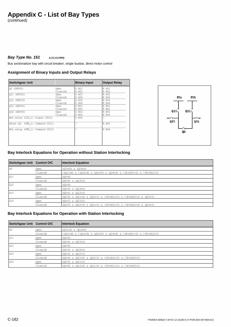
Appendix C - List of Bay Types (continued)
C-182 P439/EN M/Bd4 // AFSV.12.10190 D /// P439-304-407/408-615
Bay Type No. 151 (L15.113.M05) Bus sectionalizer bay with circuit breaker, single busbar, direct motor control
Assignment of Binary Inputs and Output Relays
Switchgear Unit Binary Input Output Relay
Q0 (DEV01) Q11 (DEV02) Q12 (DEV03) Q15 (DEV04) Q16 (DEV05) Mot.relay (SIG_1: Signal S012) Shunt wd. (CMD_1: Command C011) Mot.relay (CMD_1: Command C012)
Open Close(d) Open Close(d) Open Close(d) Open Close(d) Open Close(d)
U A01 U A02 U A03 U A04 U A05 U A06 U B01 U B02 U B03 U B04 U B06 / /
K A01 K A02 K A03 K A04 K A05 K A06 K B01 K B02 K B03 K B04 / K B05 K B06
Bay Interlock Equations for Operation without Station Interlocking
Switchgear Unit Control O/C Interlock Equation
Q0 Open (Q15=0) & (Q16=0)
Close(d) /(Q11=X) & /(Q12=X) & (Q15=0) & (Q16=0) & /(FctBl1=I) & /(FctBl2=I)
Q11 Open (Q0=0)
Close(d) (Q0=0) & (Q15=0)
Q12 Open (Q0=0)
Close(d) (Q0=0) & (Q16=0)
Q15 Open (Q0=I) & (Q12=I)
Close(d) (Q0=0) & (Q11=0) & (Q12=I) & /(FctBl1=I) & /(FctBl2=I) & (Q15=I)
Q16 Open (Q0=I) & (Q11=I)
Close(d) (Q0=0) & (Q12=0) & (Q11=I) & /(FctBl1=I) & /(FctBl2=I) & (Q16=I)
Bay Interlock Equations for Operation with Station Interlocking
Switchgear Unit Control O/C Interlock Equation
Q0 Open (Q15=0) & (Q16=0)
Close(d) /(Q11=X) & /(Q12=X) & (Q15=0) & (Q16=0) & /(FctBl1=I) & /(FctBl2=I)
Q11 Open (Q0=0)
Close(d) (Q0=0) & (Q15=0)
Q12 Open (Q0=0)
Close(d) (Q0=0) & (Q16=0)
Q15 Open (Q0=I) & (Q12=I)
Close(d) (Q0=0) & (Q11=0) & (Q12=I) & /(FctBl1=I) & /(FctBl2=I)
Q16 Open (Q0=I) & (Q11=I)
Close(d) (Q0=0) & (Q12=0) & (Q11=I) & /(FctBl1=I) & /(FctBl2=I)

Appendix C - List of Bay Types (continued)
P439/EN M/Bd4 // AFSV.12.10190 D /// P439-304-407/408-615 C-183
Bay Type No. 152 (L15.113.R01) Bus sectionalizer bay with circuit breaker, single busbar
Assignment of Binary Inputs and Output Relays
Switchgear Unit Binary Input Output Relay
Q0 (DEV01) Q11 (DEV02) Q12 (DEV03) Q15 (DEV04) Q16 (DEV05)
Open Close(d) Open Close(d) Open Close(d) Open Close(d) Open Close(d)
U A01 U A02 U A03 U A04 U A05 U A06 U B01 U B02 U B03 U B04
K A01 K A02 / / / / / / / /
Bay Interlock Equations for Operation without Station Interlocking
Switchgear Unit Control O/C Interlock Equation
Q0 Open (Q15=0) & (Q16=0)
Close(d) /(Q11=X) & /(Q12=X) & (Q15=0) & (Q16=0) & /(FctBl1=I) & /(FctBl2=I)
Bay Interlock Equations for Operation with Station Interlocking
Switchgear Unit Control O/C Interlock Equation
Q0 Open (Q15=0) & (Q16=0)
Close(d) /(Q11=X) & /(Q12=X) & (Q15=0) & (Q16=0) & /(FctBl1=I) & /(FctBl2=I)

Appendix C - List of Bay Types (continued)
C-184 P439/EN M/Bd4 // AFSV.12.10190 D /// P439-304-407/408-615
Bay Type No. 227 (L15.113.R03) Bus sectionalizer bay with circuit breaker, single busbar
Assignment of Binary Inputs and Output Relays
Switchgear Unit Binary Input Output Relay
Q0 (DEV01) Q11 (DEV02) Q12 (DEV03) Q15 (DEV04) Q16 (DEV05)
Open Close(d) Open Close(d) Open Close(d) Open Close(d) Open Close(d)
U A01 U A02 U A03 U A04 U A05 U A06 U B01 U B02 U B03 U B04
K A01 K A02 K A03 K A04 K A05 K A06 / / / /
Bay Interlock Equations for Operation without Station Interlocking
Switchgear Unit Control O/C Interlock Equation
Q0 Open (Q15=0) & (Q16=0)
Close(d) /(Q11=X) & /(Q12=X) & (Q15=0) & (Q16=0) & /(FctBl1=I) & /(FctBl2=I)
Q11 Open (Q0=0)
Close(d) (Q0=0) & (Q15=0)
Q12 Open (Q0=0)
Close(d) (Q0=0) & (Q16=0)
Bay Interlock Equations for Operation with Station Interlocking
Switchgear Unit Control O/C Interlock Equation
Q0 Open (Q15=0) & (Q16=0)
Close(d) /(Q11=X) & /(Q12=X) & (Q15=0) & (Q16=0) & /(FctBl1=I) & /(FctBl2=I)
Q11 Open (Q0=0)
Close(d) (Q0=0) & (Q15=0)
Q12 Open (Q0=0)
Close(d) (Q0=0) & (Q16=0)

Appendix C - List of Bay Types (continued)
P439/EN M/Bd4 // AFSV.12.10190 D /// P439-304-407/408-615 C-185
Bay Type No. 153 (L15.113.R05) Bus sectionalizer bay with circuit breaker, single busbar
Assignment of Binary Inputs and Output Relays
Switchgear Unit Binary Input Output Relay
Q0 (DEV01) Q11 (DEV02) Q12 (DEV03) Q15 (DEV04) Q16 (DEV05)
Open Close(d) Open Close(d) Open Close(d) Open Close(d) Open Close(d)
U A01 U A02 U A03 U A04 U A05 U A06 U B01 U B02 U B03 U B04
K A01 K A02 K A03 K A04 K A05 K A06 K B01 K B02 K B03 K B04
Bay Interlock Equations for Operation without Station Interlocking
Switchgear Unit Control O/C Interlock Equation
Q0 Open (Q15=0) & (Q16=0)
Close(d) /(Q11=X) & /(Q12=X) & (Q15=0) & (Q16=0) & /(FctBl1=I) & /(FctBl2=I)
Q11 Open (Q0=0)
Close(d) (Q0=0) & (Q15=0)
Q12 Open (Q0=0)
Close(d) (Q0=0) & (Q16=0)
Q15 Open (Q0=I) & (Q12=I)
Close(d) (Q0=0) & (Q11=0) & (Q12=I) & /(FctBl1=I) & /(FctBl2=I) & (Q15=I)
Q16 Open (Q0=I) & (Q11=I)
Close(d) (Q0=0) & (Q12=0) & (Q11=I) & /(FctBl1=I) & /(FctBl2=I) & (Q16=I)
Bay Interlock Equations for Operation with Station Interlocking
Switchgear Unit Control O/C Interlock Equation
Q0 Open (Q15=0) & (Q16=0)
Close(d) /(Q11=X) & /(Q12=X) & (Q15=0) & (Q16=0) & /(FctBl1=I) & /(FctBl2=I)
Q11 Open (Q0=0)
Close(d) (Q0=0) & (Q15=0)
Q12 Open (Q0=0)
Close(d) (Q0=0) & (Q16=0)
Q15 Open (Q0=I) & (Q12=I)
Close(d) (Q0=0) & (Q11=0) & (Q12=I) & /(FctBl1=I) & /(FctBl2=I)
Q16 Open (Q0=I) & (Q11=I)
Close(d) (Q0=0) & (Q12=0) & (Q11=I) & /(FctBl1=I) & /(FctBl2=I)
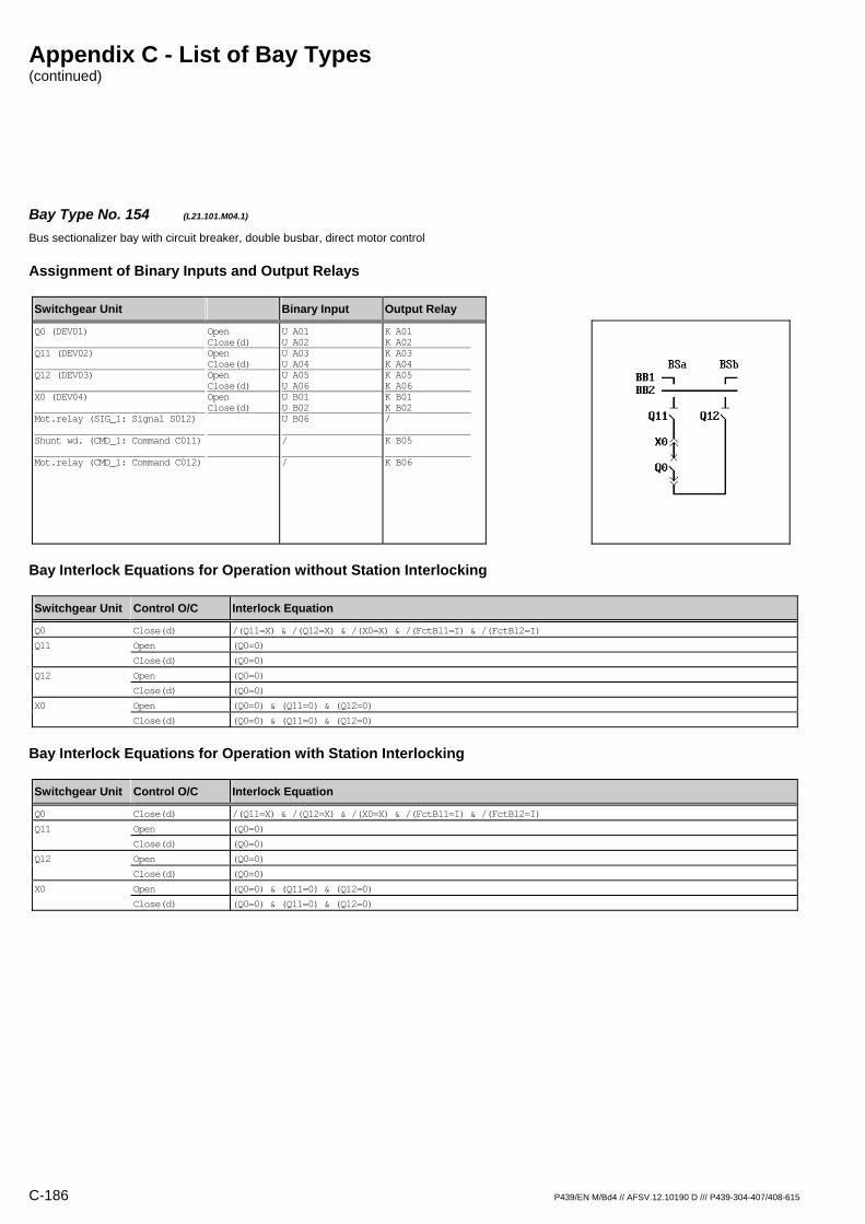
Appendix C - List of Bay Types (continued)
C-186 P439/EN M/Bd4 // AFSV.12.10190 D /// P439-304-407/408-615
Bay Type No. 154 (L21.101.M04.1) Bus sectionalizer bay with circuit breaker, double busbar, direct motor control
Assignment of Binary Inputs and Output Relays
Switchgear Unit Binary Input Output Relay
Q0 (DEV01) Q11 (DEV02) Q12 (DEV03) X0 (DEV04) Mot.relay (SIG_1: Signal S012) Shunt wd. (CMD_1: Command C011) Mot.relay (CMD_1: Command C012)
Open Close(d) Open Close(d) Open Close(d) Open Close(d)
U A01 U A02 U A03 U A04 U A05 U A06 U B01 U B02 U B06 / /
K A01 K A02 K A03 K A04 K A05 K A06 K B01 K B02 / K B05 K B06
Bay Interlock Equations for Operation without Station Interlocking
Switchgear Unit Control O/C Interlock Equation
Q0 Close(d) /(Q11=X) & /(Q12=X) & /(X0=X) & /(FctBl1=I) & /(FctBl2=I)
Q11 Open (Q0=0)
Close(d) (Q0=0)
Q12 Open (Q0=0)
Close(d) (Q0=0)
X0 Open (Q0=0) & (Q11=0) & (Q12=0)
Close(d) (Q0=0) & (Q11=0) & (Q12=0)
Bay Interlock Equations for Operation with Station Interlocking
Switchgear Unit Control O/C Interlock Equation
Q0 Close(d) /(Q11=X) & /(Q12=X) & /(X0=X) & /(FctBl1=I) & /(FctBl2=I)
Q11 Open (Q0=0)
Close(d) (Q0=0)
Q12 Open (Q0=0)
Close(d) (Q0=0)
X0 Open (Q0=0) & (Q11=0) & (Q12=0)
Close(d) (Q0=0) & (Q11=0) & (Q12=0)

Appendix C - List of Bay Types (continued)
P439/EN M/Bd4 // AFSV.12.10190 D /// P439-304-407/408-615 C-187
Bay Type No. 155 (L21.101.M04.2) Bus sectionalizer bay with circuit breaker, double busbar, direct motor control
Assignment of Binary Inputs and Output Relays
Switchgear Unit Binary Input Output Relay
Q0 (DEV01) Q21 (DEV02) Q22 (DEV03) X0 (DEV04) Mot.relay (SIG_1: Signal S012) Shunt wd. (CMD_1: Command C011) Mot.relay (CMD_1: Command C012)
Open Close(d) Open Close(d) Open Close(d) Open Close(d)
U A01 U A02 U A03 U A04 U A05 U A06 U B01 U B02 U B06 / /
K A01 K A02 K A03 K A04 K A05 K A06 K B01 K B02 / K B05 K B06
Bay Interlock Equations for Operation without Station Interlocking
Switchgear Unit Control O/C Interlock Equation
Q0 Close(d) /(Q21=X) & /(Q22=X) & /(X0=X) & /(FctBl1=I) & /(FctBl2=I)
Q21 Open (Q0=0)
Close(d) (Q0=0)
Q22 Open (Q0=0)
Close(d) (Q0=0)
X0 Open (Q0=0) & (Q21=0) & (Q22=0)
Close(d) (Q0=0) & (Q21=0) & (Q22=0)
Bay Interlock Equations for Operation with Station Interlocking
Switchgear Unit Control O/C Interlock Equation
Q0 Close(d) /(Q21=X) & /(Q22=X) & /(X0=X) & /(FctBl1=I) & /(FctBl2=I)
Q21 Open (Q0=0)
Close(d) (Q0=0)
Q22 Open (Q0=0)
Close(d) (Q0=0)
X0 Open (Q0=0) & (Q21=0) & (Q22=0)
Close(d) (Q0=0) & (Q21=0) & (Q22=0)
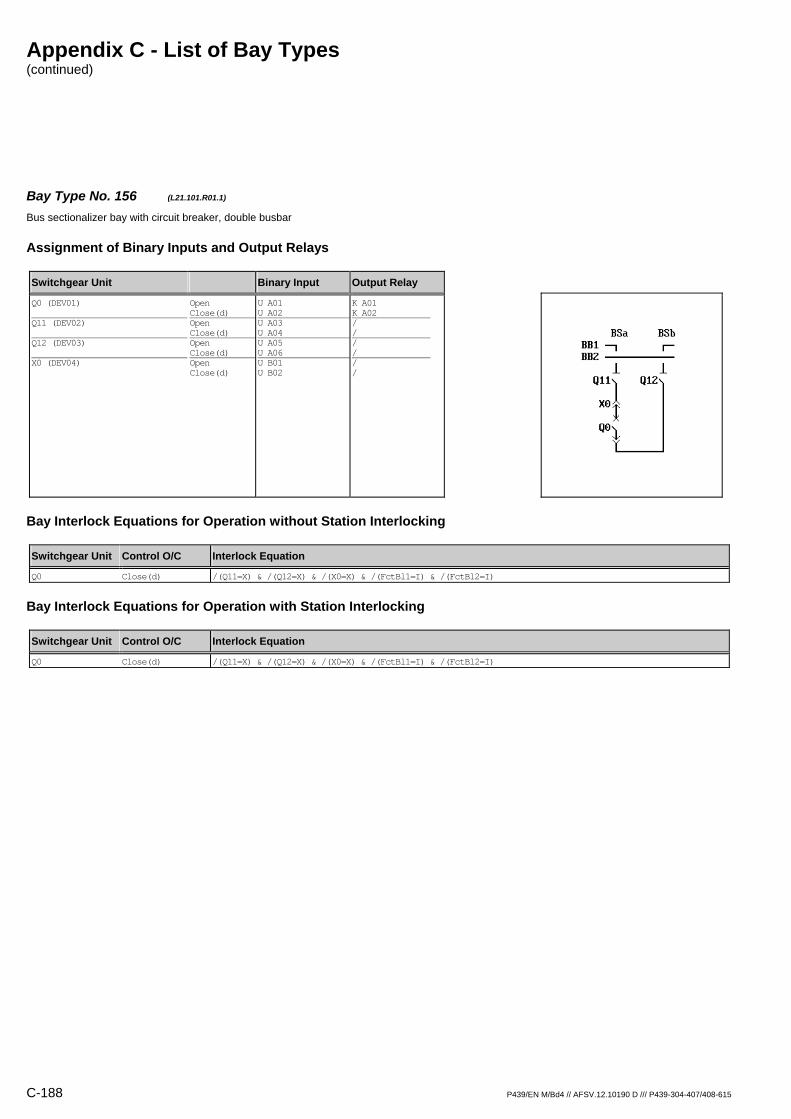
Appendix C - List of Bay Types (continued)
C-188 P439/EN M/Bd4 // AFSV.12.10190 D /// P439-304-407/408-615
Bay Type No. 156 (L21.101.R01.1) Bus sectionalizer bay with circuit breaker, double busbar
Assignment of Binary Inputs and Output Relays
Switchgear Unit Binary Input Output Relay
Q0 (DEV01) Q11 (DEV02) Q12 (DEV03) X0 (DEV04)
Open Close(d) Open Close(d) Open Close(d) Open Close(d)
U A01 U A02 U A03 U A04 U A05 U A06 U B01 U B02
K A01 K A02 / / / / / /
Bay Interlock Equations for Operation without Station Interlocking
Switchgear Unit Control O/C Interlock Equation
Q0 Close(d) /(Q11=X) & /(Q12=X) & /(X0=X) & /(FctBl1=I) & /(FctBl2=I)
Bay Interlock Equations for Operation with Station Interlocking
Switchgear Unit Control O/C Interlock Equation
Q0 Close(d) /(Q11=X) & /(Q12=X) & /(X0=X) & /(FctBl1=I) & /(FctBl2=I)

Appendix C - List of Bay Types (continued)
P439/EN M/Bd4 // AFSV.12.10190 D /// P439-304-407/408-615 C-189
Bay Type No. 157 (L21.101.R01.2) Bus sectionalizer bay with circuit breaker, double busbar
Assignment of Binary Inputs and Output Relays
Switchgear Unit Binary Input Output Relay
Q0 (DEV01) Q21 (DEV02) Q22 (DEV03) X0 (DEV04)
Open Close(d) Open Close(d) Open Close(d) Open Close(d)
U A01 U A02 U A03 U A04 U A05 U A06 U B01 U B02
K A01 K A02 / / / / / /
Bay Interlock Equations for Operation without Station Interlocking
Switchgear Unit Control O/C Interlock Equation
Q0 Close(d) /(Q21=X) & /(Q22=X) & /(X0=X) & /(FctBl1=I) & /(FctBl2=I)
Bay Interlock Equations for Operation with Station Interlocking
Switchgear Unit Control O/C Interlock Equation
Q0 Close(d) /(Q21=X) & /(Q22=X) & /(X0=X) & /(FctBl1=I) & /(FctBl2=I)
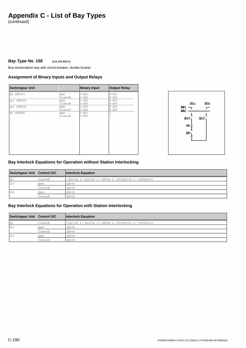
Appendix C - List of Bay Types (continued)
C-190 P439/EN M/Bd4 // AFSV.12.10190 D /// P439-304-407/408-615
Bay Type No. 158 (L21.101.R03.1) Bus sectionalizer bay with circuit breaker, double busbar
Assignment of Binary Inputs and Output Relays
Switchgear Unit Binary Input Output Relay
Q0 (DEV01) Q11 (DEV02) Q12 (DEV03) X0 (DEV04)
Open Close(d) Open Close(d) Open Close(d) Open Close(d)
U A01 U A02 U A03 U A04 U A05 U A06 U B01 U B02
K A01 K A02 K A03 K A04 K A05 K A06 / /
Bay Interlock Equations for Operation without Station Interlocking
Switchgear Unit Control O/C Interlock Equation
Q0 Close(d) /(Q11=X) & /(Q12=X) & /(X0=X) & /(FctBl1=I) & /(FctBl2=I)
Q11 Open (Q0=0)
Close(d) (Q0=0)
Q12 Open (Q0=0)
Close(d) (Q0=0)
Bay Interlock Equations for Operation with Station Interlocking
Switchgear Unit Control O/C Interlock Equation
Q0 Close(d) /(Q11=X) & /(Q12=X) & /(X0=X) & /(FctBl1=I) & /(FctBl2=I)
Q11 Open (Q0=0)
Close(d) (Q0=0)
Q12 Open (Q0=0)
Close(d) (Q0=0)

Appendix C - List of Bay Types (continued)
P439/EN M/Bd4 // AFSV.12.10190 D /// P439-304-407/408-615 C-191
Bay Type No. 159 (L21.101.R03.2) Bus sectionalizer bay with circuit breaker, double busbar
Assignment of Binary Inputs and Output Relays
Switchgear Unit Binary Input Output Relay
Q0 (DEV01) Q21 (DEV02) Q22 (DEV03) X0 (DEV04)
Open Close(d) Open Close(d) Open Close(d) Open Close(d)
U A01 U A02 U A03 U A04 U A05 U A06 U B01 U B02
K A01 K A02 K A03 K A04 K A05 K A06 / /
Bay Interlock Equations for Operation without Station Interlocking
Switchgear Unit Control O/C Interlock Equation
Q0 Close(d) /(Q21=X) & /(Q22=X) & /(X0=X) & /(FctBl1=I) & /(FctBl2=I)
Q21 Open (Q0=0)
Close(d) (Q0=0)
Q22 Open (Q0=0)
Close(d) (Q0=0)
Bay Interlock Equations for Operation with Station Interlocking
Switchgear Unit Control O/C Interlock Equation
Q0 Close(d) /(Q21=X) & /(Q22=X) & /(X0=X) & /(FctBl1=I) & /(FctBl2=I)
Q21 Open (Q0=0)
Close(d) (Q0=0)
Q22 Open (Q0=0)
Close(d) (Q0=0)
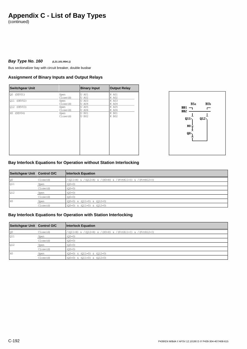
Appendix C - List of Bay Types (continued)
C-192 P439/EN M/Bd4 // AFSV.12.10190 D /// P439-304-407/408-615
Bay Type No. 160 (L21.101.R04.1) Bus sectionalizer bay with circuit breaker, double busbar
Assignment of Binary Inputs and Output Relays
Switchgear Unit Binary Input Output Relay
Q0 (DEV01) Q11 (DEV02) Q12 (DEV03) X0 (DEV04)
Open Close(d) Open Close(d) Open Close(d) Open Close(d)
U A01 U A02 U A03 U A04 U A05 U A06 U B01 U B02
K A01 K A02 K A03 K A04 K A05 K A06 K B01 K B02
Bay Interlock Equations for Operation without Station Interlocking
Switchgear Unit Control O/C Interlock Equation
Q0 Close(d) /(Q11=X) & /(Q12=X) & /(X0=X) & /(FctBl1=I) & /(FctBl2=I)
Q11 Open (Q0=0)
Close(d) (Q0=0)
Q12 Open (Q0=0)
Close(d) (Q0=0)
X0 Open (Q0=0) & (Q11=0) & (Q12=0)
Close(d) (Q0=0) & (Q11=0) & (Q12=0)
Bay Interlock Equations for Operation with Station Interlocking
Switchgear Unit Control O/C Interlock Equation
Q0 Close(d) /(Q11=X) & /(Q12=X) & /(X0=X) & /(FctBl1=I) & /(FctBl2=I)
Q11 Open (Q0=0)
Close(d) (Q0=0)
Q12 Open (Q0=0)
Close(d) (Q0=0)
X0 Open (Q0=0) & (Q11=0) & (Q12=0)
Close(d) (Q0=0) & (Q11=0) & (Q12=0)

Appendix C - List of Bay Types (continued)
P439/EN M/Bd4 // AFSV.12.10190 D /// P439-304-407/408-615 C-193
Bay Type No. 161 (L21.101.R04.2) Bus sectionalizer bay with circuit breaker, double busbar
Assignment of Binary Inputs and Output Relays
Switchgear Unit Binary Input Output Relay
Q0 (DEV01) Q21 (DEV02) Q22 (DEV03) X0 (DEV04)
Open Close(d) Open Close(d) Open Close(d) Open Close(d)
U A01 U A02 U A03 U A04 U A05 U A06 U B01 U B02
K A01 K A02 K A03 K A04 K A05 K A06 K B01 K B02
Bay Interlock Equations for Operation without Station Interlocking
Switchgear Unit Control O/C Interlock Equation
Q0 Close(d) /(Q21=X) & /(Q22=X) & /(X0=X) & /(FctBl1=I) & /(FctBl2=I)
Q21 Open (Q0=0)
Close(d) (Q0=0)
Q22 Open (Q0=0)
Close(d) (Q0=0)
X0 Open (Q0=0) & (Q21=0) & (Q22=0)
Close(d) (Q0=0) & (Q21=0) & (Q22=0)
Bay Interlock Equations for Operation with Station Interlocking
Switchgear Unit Control O/C Interlock Equation
Q0 Close(d) /(Q21=X) & /(Q22=X) & /(X0=X) & /(FctBl1=I) & /(FctBl2=I)
Q21 Open (Q0=0)
Close(d) (Q0=0)
Q22 Open (Q0=0)
Close(d) (Q0=0)
X0 Open (Q0=0) & (Q21=0) & (Q22=0)
Close(d) (Q0=0) & (Q21=0) & (Q22=0)

Appendix C - List of Bay Types (continued)
C-194 P439/EN M/Bd4 // AFSV.12.10190 D /// P439-304-407/408-615
Bay Type No. 513 (L21.109.R03.1) Bus sectionalizer bay with circuit breaker, double busbar
Assignment of Binary Inputs and Output Relays
Switchgear Unit Binary Input Output Relay
Q0 (DEV01) Q11 (DEV02) Q12 (DEV03) X0 (DEV04) Q8 (DEV05)
Open Close(d) Open Close(d) Open Close(d) Open Close(d) Open Close(d)
U A01 U A02 U A03 U A04 U A05 U A06 U B01 U B02 U B03 U B04
K A01 K A02 K A03 K A04 K A05 K A06 / / / /
Bay Interlock Equations for Operation without Station Interlocking
Switchgear Unit Control O/C Interlock Equation
Q0 Close(d) /(Q11=X) & /(Q12=X) & /(X0=X) & (Q8=0) & /(FctBl1=I) & /(FctBl2=I)
Q11 Open (Q0=0)
Close(d) (Q0=0) & (Q8=0)
Q12 Open (Q0=0)
Close(d) (Q0=0) & (Q8=0)
Bay Interlock Equations for Operation with Station Interlocking
Switchgear Unit Control O/C Interlock Equation
Q0 Close(d) /(Q11=X) & /(Q12=X) & /(X0=X) & (Q8=0) & /(FctBl1=I) & /(FctBl2=I)
Q11 Open (Q0=0)
Close(d) (Q0=0) & (Q8=0)
Q12 Open (Q0=0)
Close(d) (Q0=0) & (Q8=0)

Appendix C - List of Bay Types (continued)
P439/EN M/Bd4 // AFSV.12.10190 D /// P439-304-407/408-615 C-195
Bay Type No. 514 (L21.109.R03.2) Bus sectionalizer bay with circuit breaker, double busbar
Assignment of Binary Inputs and Output Relays
Switchgear Unit Binary Input Output Relay
Q0 (DEV01) Q21 (DEV02) Q22 (DEV03) X0 (DEV04) Q8 (DEV05)
Open Close(d) Open Close(d) Open Close(d) Open Close(d) Open Close(d)
U A01 U A02 U A03 U A04 U A05 U A06 U B01 U B02 U B03 U B04
K A01 K A02 K A03 K A04 K A05 K A06 / / / /
Bay Interlock Equations for Operation without Station Interlocking
Switchgear Unit Control O/C Interlock Equation
Q0 Close(d) /(Q21=X) & /(Q22=X) & /(X0=X) & (Q8=0) & /(FctBl1=I) & /(FctBl2=I)
Q21 Open (Q0=0)
Close(d) (Q0=0) & (Q8=0)
Q22 Open (Q0=0)
Close(d) (Q0=0) & (Q8=0)
Bay Interlock Equations for Operation with Station Interlocking
Switchgear Unit Control O/C Interlock Equation
Q0 Close(d) /(Q21=X) & /(Q22=X) & /(X0=X) & (Q8=0) & /(FctBl1=I) & /(FctBl2=I)
Q21 Open (Q0=0)
Close(d) (Q0=0) & (Q8=0)
Q22 Open (Q0=0)
Close(d) (Q0=0) & (Q8=0)
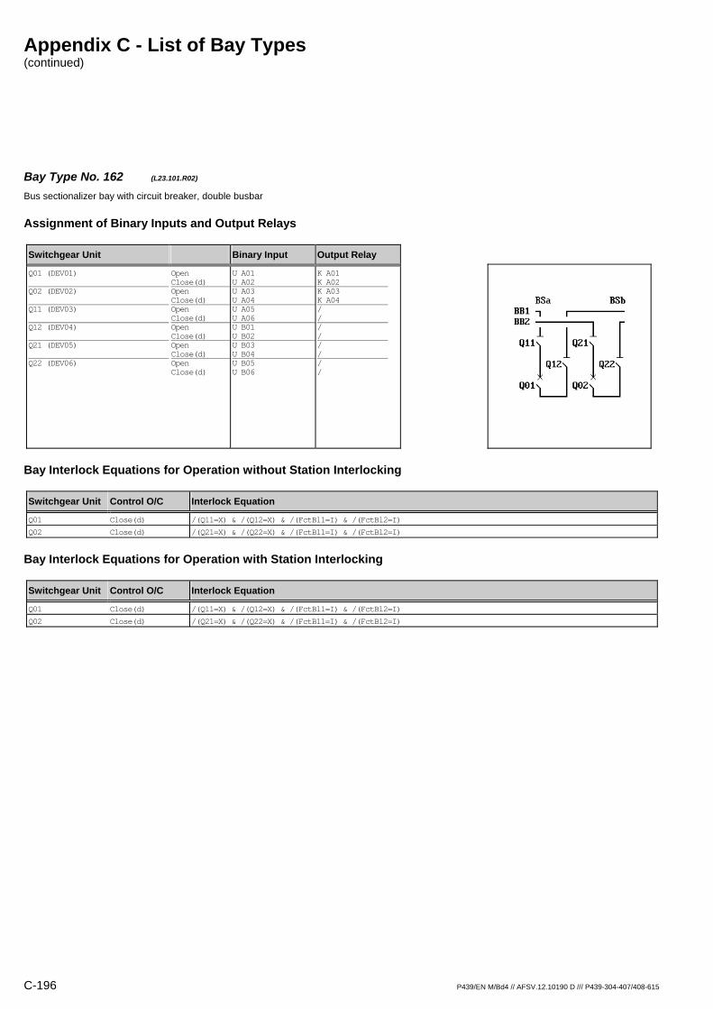
Appendix C - List of Bay Types (continued)
C-196 P439/EN M/Bd4 // AFSV.12.10190 D /// P439-304-407/408-615
Bay Type No. 162 (L23.101.R02) Bus sectionalizer bay with circuit breaker, double busbar
Assignment of Binary Inputs and Output Relays
Switchgear Unit Binary Input Output Relay
Q01 (DEV01) Q02 (DEV02) Q11 (DEV03) Q12 (DEV04) Q21 (DEV05) Q22 (DEV06)
Open Close(d) Open Close(d) Open Close(d) Open Close(d) Open Close(d) Open Close(d)
U A01 U A02 U A03 U A04 U A05 U A06 U B01 U B02 U B03 U B04 U B05 U B06
K A01 K A02 K A03 K A04 / / / / / / / /
Bay Interlock Equations for Operation without Station Interlocking
Switchgear Unit Control O/C Interlock Equation
Q01 Close(d) /(Q11=X) & /(Q12=X) & /(FctBl1=I) & /(FctBl2=I)
Q02 Close(d) /(Q21=X) & /(Q22=X) & /(FctBl1=I) & /(FctBl2=I)
Bay Interlock Equations for Operation with Station Interlocking
Switchgear Unit Control O/C Interlock Equation
Q01 Close(d) /(Q11=X) & /(Q12=X) & /(FctBl1=I) & /(FctBl2=I)
Q02 Close(d) /(Q21=X) & /(Q22=X) & /(FctBl1=I) & /(FctBl2=I)
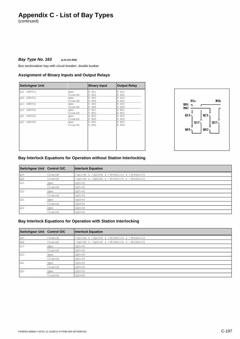
Appendix C - List of Bay Types (continued)
P439/EN M/Bd4 // AFSV.12.10190 D /// P439-304-407/408-615 C-197
Bay Type No. 163 (L23.101.R06) Bus sectionalizer bay with circuit breaker, double busbar
Assignment of Binary Inputs and Output Relays
Switchgear Unit Binary Input Output Relay
Q01 (DEV01) Q02 (DEV02) Q11 (DEV03) Q12 (DEV04) Q21 (DEV05) Q22 (DEV06)
Open Close(d) Open Close(d) Open Close(d) Open Close(d) Open Close(d) Open Close(d)
U A01 U A02 U A03 U A04 U A05 U A06 U B01 U B02 U B03 U B04 U B05 U B06
K A01 K A02 K A03 K A04 K A05 K A06 K B01 K B02 K B03 K B04 K B05 K B06
Bay Interlock Equations for Operation without Station Interlocking
Switchgear Unit Control O/C Interlock Equation
Q01 Close(d) /(Q11=X) & /(Q12=X) & /(FctBl1=I) & /(FctBl2=I)
Q02 Close(d) /(Q21=X) & /(Q22=X) & /(FctBl1=I) & /(FctBl2=I)
Q11 Open (Q01=0)
Close(d) (Q01=0)
Q12 Open (Q01=0)
Close(d) (Q01=0)
Q21 Open (Q02=0)
Close(d) (Q02=0)
Q22 Open (Q02=0)
Close(d) (Q02=0)
Bay Interlock Equations for Operation with Station Interlocking
Switchgear Unit Control O/C Interlock Equation
Q01 Close(d) /(Q11=X) & /(Q12=X) & /(FctBl1=I) & /(FctBl2=I)
Q02 Close(d) /(Q21=X) & /(Q22=X) & /(FctBl1=I) & /(FctBl2=I)
Q11 Open (Q01=0)
Close(d) (Q01=0)
Q12 Open (Q01=0)
Close(d) (Q01=0)
Q21 Open (Q02=0)
Close(d) (Q02=0)
Q22 Open (Q02=0)
Close(d) (Q02=0)

Appendix C - List of Bay Types (continued)
C-198 P439/EN M/Bd4 // AFSV.12.10190 D /// P439-304-407/408-615
Bay Type No. 554 (L23.901.M01.1) Bus sectionalizer bay with other switchgear unit, double busbar, direct motor control
Assignment of Binary Inputs and Output Relays
Switchgear Unit Binary Input Output Relay
Q11 (DEV01) Mot.relay (SIG_1: Signal S012) Shunt wd. (CMD_1: Command C011) Mot.relay (CMD_1: Command C012)
Open Close(d)
U A01 U A02 U B06 / /
K A01 K A02 / K B05 K B06
Bay Interlock Equations for Operation without Station Interlocking
Switchgear Unit Control O/C Interlock Equation
Interlock Equations not defined
Bay Interlock Equations for Operation with Station Interlocking
Switchgear Unit Control O/C Interlock Equation
Interlock Equations not defined
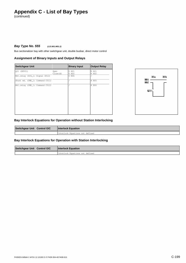
Appendix C - List of Bay Types (continued)
P439/EN M/Bd4 // AFSV.12.10190 D /// P439-304-407/408-615 C-199
Bay Type No. 555 (L23.901.M01.2) Bus sectionalizer bay with other switchgear unit, double busbar, direct motor control
Assignment of Binary Inputs and Output Relays
Switchgear Unit Binary Input Output Relay
Q21 (DEV01) Mot.relay (SIG_1: Signal S012) Shunt wd. (CMD_1: Command C011) Mot.relay (CMD_1: Command C012)
Open Close(d)
U A01 U A02 U B06 / /
K A01 K A02 / K B05 K B06
Bay Interlock Equations for Operation without Station Interlocking
Switchgear Unit Control O/C Interlock Equation
Interlock Equations not defined
Bay Interlock Equations for Operation with Station Interlocking
Switchgear Unit Control O/C Interlock Equation
Interlock Equations not defined

Appendix C - List of Bay Types (continued)
C-200 P439/EN M/Bd4 // AFSV.12.10190 D /// P439-304-407/408-615
Bay Type No. 164 (L23.901.R02) Bus sectionalizer bay with other switchgear unit, double busbar
Assignment of Binary Inputs and Output Relays
Switchgear Unit Binary Input Output Relay
Q11 (DEV01) Q21 (DEV02)
Open Close(d) Open Close(d)
U A01 U A02 U A03 U A04
K A01 K A02 K A03 K A04
Bay Interlock Equations for Operation without Station Interlocking
Switchgear Unit Control O/C Interlock Equation
Q11 Open (Q11=0)
Close(d) (Q11=I)
Q21 Open (Q21=0)
Close(d) (Q21=I)
Bay Interlock Equations for Operation with Station Interlocking
Switchgear Unit Control O/C Interlock Equation
Interlock Equations not defined

Appendix C - List of Bay Types (continued)
P439/EN M/Bd4 // AFSV.12.10190 D /// P439-304-407/408-615 C-201
Bay Type No. 242 (L23.903.M01.3) Bus sectionalizer bay with other switchgear unit, double busbar, direct motor control
Assignment of Binary Inputs and Output Relays
Switchgear Unit Binary Input Output Relay
Q12 (DEV01) Q15 (DEV02) Q25 (DEV03) Mot.relay (SIG_1: Signal S012) Shunt wd. (CMD_1: Command C011) Mot.relay (CMD_1: Command C012)
Open Close(d) Open Close(d) Open Close(d)
U A01 U A02 U A03 U A04 U A05 U A06 U B06 / /
K A01 K A02 / / / / / K B05 K B06
Bay Interlock Equations for Operation without Station Interlocking
Switchgear Unit Control O/C Interlock Equation
Q12 Open (Q12=0)
Close(d) (Q12=I)
Bay Interlock Equations for Operation with Station Interlocking
Switchgear Unit Control O/C Interlock Equation
Interlock Equations not defined
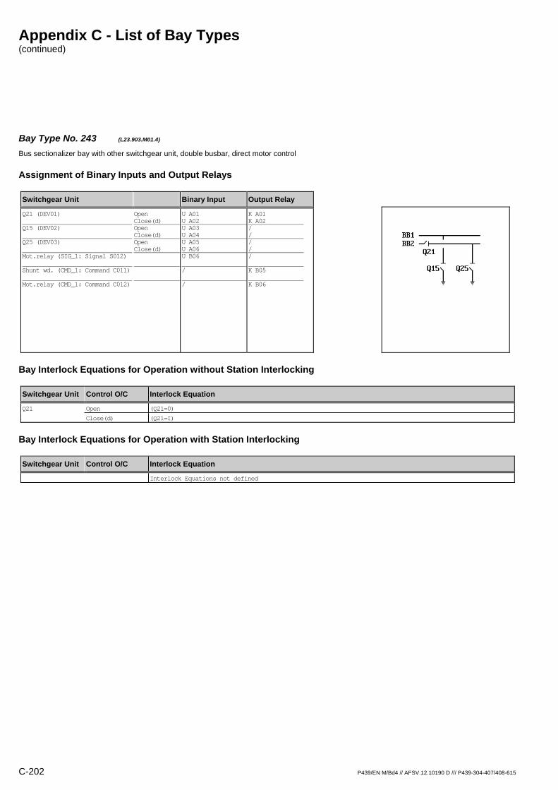
Appendix C - List of Bay Types (continued)
C-202 P439/EN M/Bd4 // AFSV.12.10190 D /// P439-304-407/408-615
Bay Type No. 243 (L23.903.M01.4) Bus sectionalizer bay with other switchgear unit, double busbar, direct motor control
Assignment of Binary Inputs and Output Relays
Switchgear Unit Binary Input Output Relay
Q21 (DEV01) Q15 (DEV02) Q25 (DEV03) Mot.relay (SIG_1: Signal S012) Shunt wd. (CMD_1: Command C011) Mot.relay (CMD_1: Command C012)
Open Close(d) Open Close(d) Open Close(d)
U A01 U A02 U A03 U A04 U A05 U A06 U B06 / /
K A01 K A02 / / / / / K B05 K B06
Bay Interlock Equations for Operation without Station Interlocking
Switchgear Unit Control O/C Interlock Equation
Q21 Open (Q21=0)
Close(d) (Q21=I)
Bay Interlock Equations for Operation with Station Interlocking
Switchgear Unit Control O/C Interlock Equation
Interlock Equations not defined
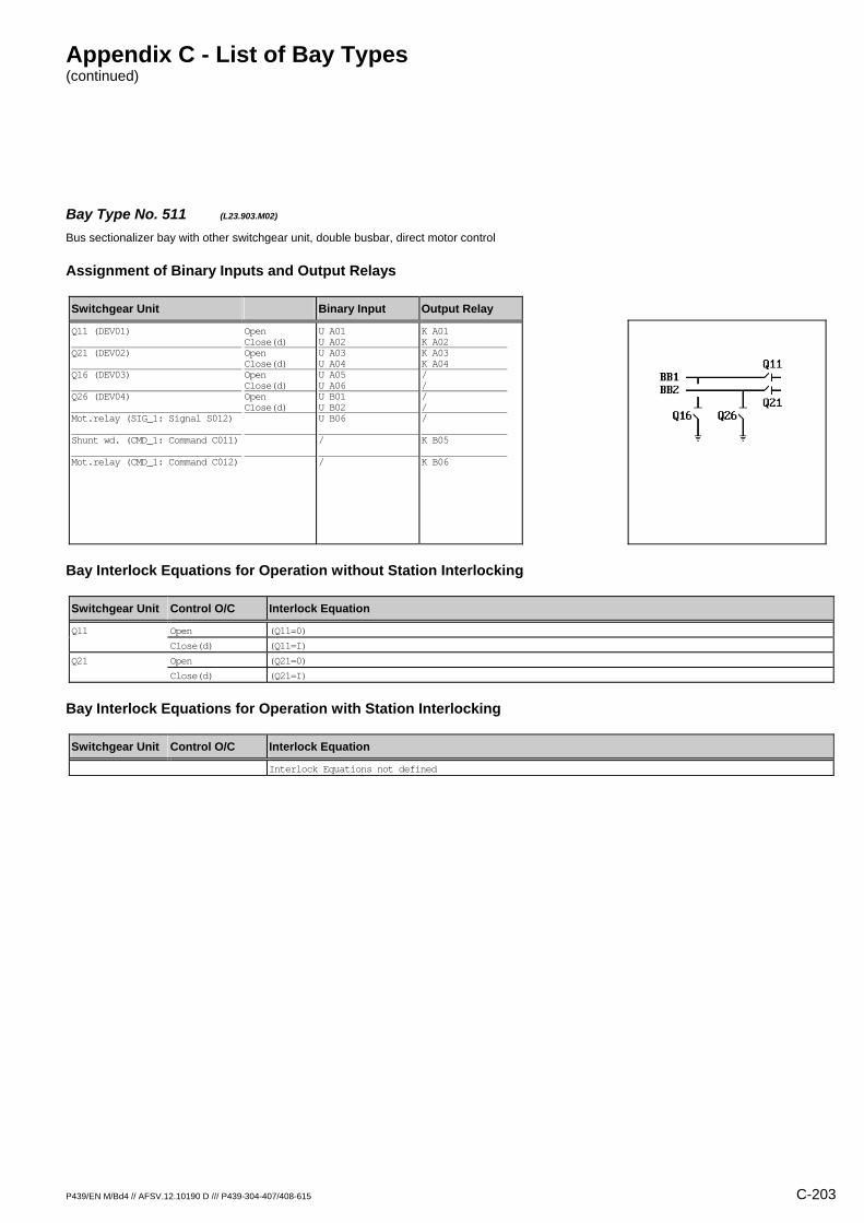
Appendix C - List of Bay Types (continued)
P439/EN M/Bd4 // AFSV.12.10190 D /// P439-304-407/408-615 C-203
Bay Type No. 511 (L23.903.M02) Bus sectionalizer bay with other switchgear unit, double busbar, direct motor control
Assignment of Binary Inputs and Output Relays
Switchgear Unit Binary Input Output Relay
Q11 (DEV01) Q21 (DEV02) Q16 (DEV03) Q26 (DEV04) Mot.relay (SIG_1: Signal S012) Shunt wd. (CMD_1: Command C011) Mot.relay (CMD_1: Command C012)
Open Close(d) Open Close(d) Open Close(d) Open Close(d)
U A01 U A02 U A03 U A04 U A05 U A06 U B01 U B02 U B06 / /
K A01 K A02 K A03 K A04 / / / / / K B05 K B06
Bay Interlock Equations for Operation without Station Interlocking
Switchgear Unit Control O/C Interlock Equation
Q11 Open (Q11=0)
Close(d) (Q11=I)
Q21 Open (Q21=0)
Close(d) (Q21=I)
Bay Interlock Equations for Operation with Station Interlocking
Switchgear Unit Control O/C Interlock Equation
Interlock Equations not defined

Appendix C - List of Bay Types (continued)
C-204 P439/EN M/Bd4 // AFSV.12.10190 D /// P439-304-407/408-615
Bay Type No. 228 (L25.113.M03.1) Bus sectionalizer bay with circuit breaker, double busbar, direct motor control
Assignment of Binary Inputs and Output Relays
Switchgear Unit Binary Input Output Relay
Q0 (DEV01) Q11 (DEV02) Q12 (DEV03) Q15 (DEV04) Q16 (DEV05) Mot.relay (SIG_1: Signal S012) Shunt wd. (CMD_1: Command C011) Mot.relay (CMD_1: Command C012)
Open Close(d) Open Close(d) Open Close(d) Open Close(d) Open Close(d)
U A01 U A02 U A03 U A04 U A05 U A06 U B01 U B02 U B03 U B04 U B06 / /
K A01 K A02 K A03 K A04 K A05 K A06 / / / / / K B05 K B06
Bay Interlock Equations for Operation without Station Interlocking
Switchgear Unit Control O/C Interlock Equation
Q0 Open (Q15=0) & (Q16=0)
Close(d) /(Q11=X) & /(Q12=X) & (Q15=0) & (Q16=0) & /(FctBl1=I) & /(FctBl2=I)
Q11 Open (Q0=0)
Close(d) (Q0=0) & (Q15=0)
Q12 Open (Q0=0)
Close(d) (Q0=0) & (Q16=0)
Bay Interlock Equations for Operation with Station Interlocking
Switchgear Unit Control O/C Interlock Equation
Q0 Open (Q15=0) & (Q16=0)
Close(d) /(Q11=X) & /(Q12=X) & (Q15=0) & (Q16=0) & /(FctBl1=I) & /(FctBl2=I)
Q11 Open (Q0=0)
Close(d) (Q0=0) & (Q15=0)
Q12 Open (Q0=0)
Close(d) (Q0=0) & (Q16=0)
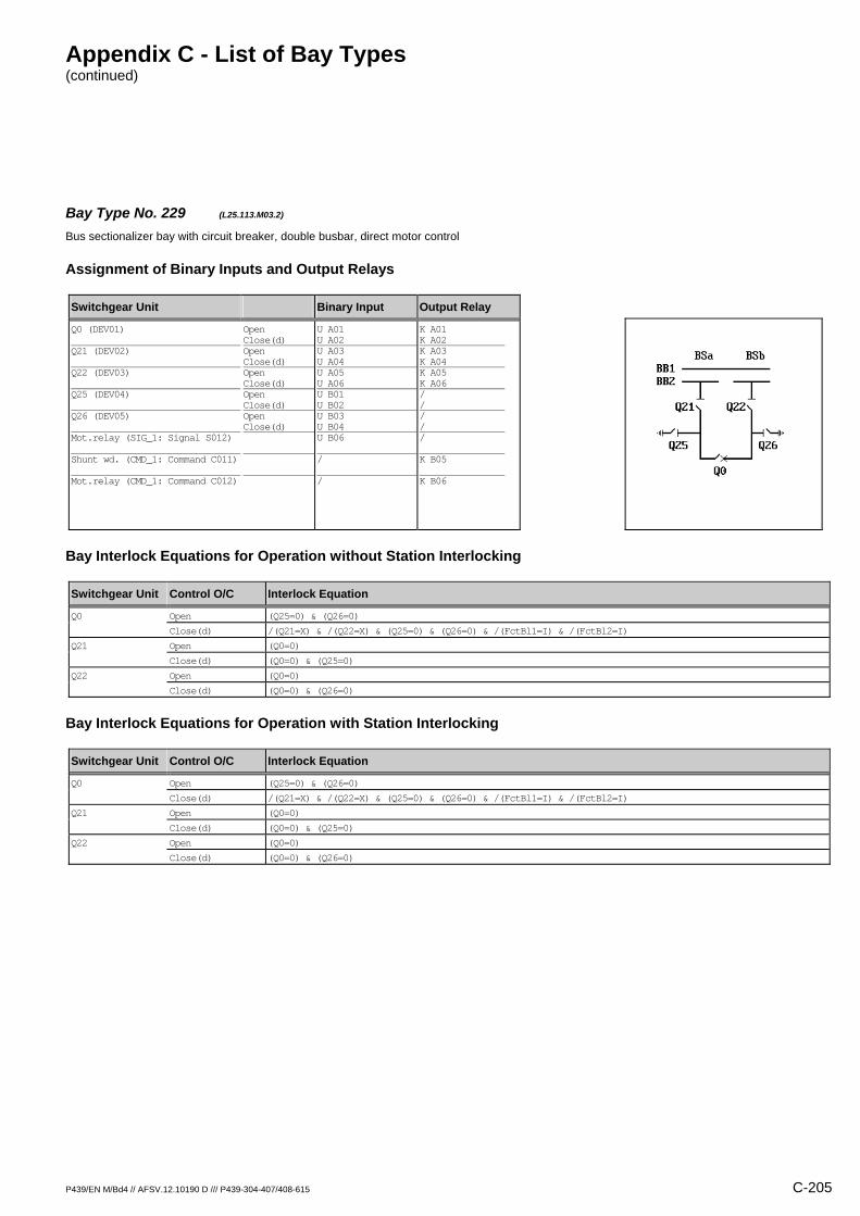
Appendix C - List of Bay Types (continued)
P439/EN M/Bd4 // AFSV.12.10190 D /// P439-304-407/408-615 C-205
Bay Type No. 229 (L25.113.M03.2) Bus sectionalizer bay with circuit breaker, double busbar, direct motor control
Assignment of Binary Inputs and Output Relays
Switchgear Unit Binary Input Output Relay
Q0 (DEV01) Q21 (DEV02) Q22 (DEV03) Q25 (DEV04) Q26 (DEV05) Mot.relay (SIG_1: Signal S012) Shunt wd. (CMD_1: Command C011) Mot.relay (CMD_1: Command C012)
Open Close(d) Open Close(d) Open Close(d) Open Close(d) Open Close(d)
U A01 U A02 U A03 U A04 U A05 U A06 U B01 U B02 U B03 U B04 U B06 / /
K A01 K A02 K A03 K A04 K A05 K A06 / / / / / K B05 K B06
Bay Interlock Equations for Operation without Station Interlocking
Switchgear Unit Control O/C Interlock Equation
Q0 Open (Q25=0) & (Q26=0)
Close(d) /(Q21=X) & /(Q22=X) & (Q25=0) & (Q26=0) & /(FctBl1=I) & /(FctBl2=I)
Q21 Open (Q0=0)
Close(d) (Q0=0) & (Q25=0)
Q22 Open (Q0=0)
Close(d) (Q0=0) & (Q26=0)
Bay Interlock Equations for Operation with Station Interlocking
Switchgear Unit Control O/C Interlock Equation
Q0 Open (Q25=0) & (Q26=0)
Close(d) /(Q21=X) & /(Q22=X) & (Q25=0) & (Q26=0) & /(FctBl1=I) & /(FctBl2=I)
Q21 Open (Q0=0)
Close(d) (Q0=0) & (Q25=0)
Q22 Open (Q0=0)
Close(d) (Q0=0) & (Q26=0)
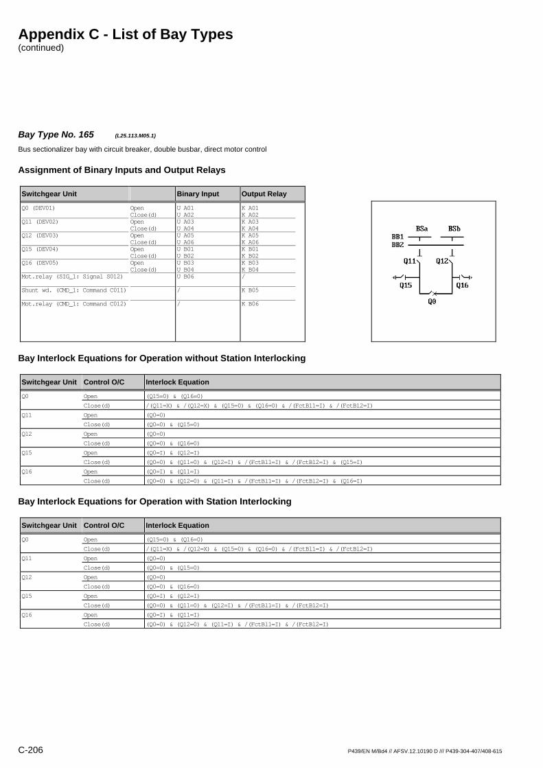
Appendix C - List of Bay Types (continued)
C-206 P439/EN M/Bd4 // AFSV.12.10190 D /// P439-304-407/408-615
Bay Type No. 165 (L25.113.M05.1) Bus sectionalizer bay with circuit breaker, double busbar, direct motor control
Assignment of Binary Inputs and Output Relays
Switchgear Unit Binary Input Output Relay
Q0 (DEV01) Q11 (DEV02) Q12 (DEV03) Q15 (DEV04) Q16 (DEV05) Mot.relay (SIG_1: Signal S012) Shunt wd. (CMD_1: Command C011) Mot.relay (CMD_1: Command C012)
Open Close(d) Open Close(d) Open Close(d) Open Close(d) Open Close(d)
U A01 U A02 U A03 U A04 U A05 U A06 U B01 U B02 U B03 U B04 U B06 / /
K A01 K A02 K A03 K A04 K A05 K A06 K B01 K B02 K B03 K B04 / K B05 K B06
Bay Interlock Equations for Operation without Station Interlocking
Switchgear Unit Control O/C Interlock Equation
Q0 Open (Q15=0) & (Q16=0)
Close(d) /(Q11=X) & /(Q12=X) & (Q15=0) & (Q16=0) & /(FctBl1=I) & /(FctBl2=I)
Q11 Open (Q0=0)
Close(d) (Q0=0) & (Q15=0)
Q12 Open (Q0=0)
Close(d) (Q0=0) & (Q16=0)
Q15 Open (Q0=I) & (Q12=I)
Close(d) (Q0=0) & (Q11=0) & (Q12=I) & /(FctBl1=I) & /(FctBl2=I) & (Q15=I)
Q16 Open (Q0=I) & (Q11=I)
Close(d) (Q0=0) & (Q12=0) & (Q11=I) & /(FctBl1=I) & /(FctBl2=I) & (Q16=I)
Bay Interlock Equations for Operation with Station Interlocking
Switchgear Unit Control O/C Interlock Equation
Q0 Open (Q15=0) & (Q16=0)
Close(d) /(Q11=X) & /(Q12=X) & (Q15=0) & (Q16=0) & /(FctBl1=I) & /(FctBl2=I)
Q11 Open (Q0=0)
Close(d) (Q0=0) & (Q15=0)
Q12 Open (Q0=0)
Close(d) (Q0=0) & (Q16=0)
Q15 Open (Q0=I) & (Q12=I)
Close(d) (Q0=0) & (Q11=0) & (Q12=I) & /(FctBl1=I) & /(FctBl2=I)
Q16 Open (Q0=I) & (Q11=I)
Close(d) (Q0=0) & (Q12=0) & (Q11=I) & /(FctBl1=I) & /(FctBl2=I)
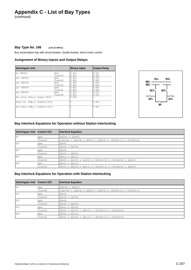
Appendix C - List of Bay Types (continued)
P439/EN M/Bd4 // AFSV.12.10190 D /// P439-304-407/408-615 C-207
Bay Type No. 166 (L25.113.M05.2) Bus sectionalizer bay with circuit breaker, double busbar, direct motor control
Assignment of Binary Inputs and Output Relays
Switchgear Unit Binary Input Output Relay
Q0 (DEV01) Q21 (DEV02) Q22 (DEV03) Q25 (DEV04) Q26 (DEV05) Mot.relay (SIG_1: Signal S012) Shunt wd. (CMD_1: Command C011) Mot.relay (CMD_1: Command C012)
Open Close(d) Open Close(d) Open Close(d) Open Close(d) Open Close(d)
U A01 U A02 U A03 U A04 U A05 U A06 U B01 U B02 U B03 U B04 U B06 / /
K A01 K A02 K A03 K A04 K A05 K A06 K B01 K B02 K B03 K B04 / K B05 K B06
Bay Interlock Equations for Operation without Station Interlocking
Switchgear Unit Control O/C Interlock Equation
Q0 Open (Q25=0) & (Q26=0)
Close(d) /(Q21=X) & /(Q22=X) & (Q25=0) & (Q26=0) & /(FctBl1=I) & /(FctBl2=I)
Q21 Open (Q0=0)
Close(d) (Q0=0) & (Q25=0)
Q22 Open (Q0=0)
Close(d) (Q0=0) & (Q26=0)
Q25 Open (Q0=I) & (Q22=I)
Close(d) (Q0=0) & (Q21=0) & (Q22=I) & /(FctBl1=I) & /(FctBl2=I) & (Q25=I)
Q26 Open (Q0=I) & (Q21=I)
Close(d) (Q0=0) & (Q22=0) & (Q21=I) & /(FctBl1=I) & /(FctBl2=I) & (Q26=I)
Bay Interlock Equations for Operation with Station Interlocking
Switchgear Unit Control O/C Interlock Equation
Q0 Open (Q25=0) & (Q26=0)
Close(d) /(Q21=X) & /(Q22=X) & (Q25=0) & (Q26=0) & /(FctBl1=I) & /(FctBl2=I)
Q21 Open (Q0=0)
Close(d) (Q0=0) & (Q25=0)
Q22 Open (Q0=0)
Close(d) (Q0=0) & (Q26=0)
Q25 Open (Q0=I) & (Q22=I)
Close(d) (Q0=0) & (Q21=0) & (Q22=I) & /(FctBl1=I) & /(FctBl2=I)
Q26 Open (Q0=I) & (Q21=I)
Close(d) (Q0=0) & (Q22=0) & (Q21=I) & /(FctBl1=I) & /(FctBl2=I)

Appendix C - List of Bay Types (continued)
C-208 P439/EN M/Bd4 // AFSV.12.10190 D /// P439-304-407/408-615
Bay Type No. 167 (L25.113.R01.1) Bus sectionalizer bay with circuit breaker, double busbar
Assignment of Binary Inputs and Output Relays
Switchgear Unit Binary Input Output Relay
Q0 (DEV01) Q11 (DEV02) Q12 (DEV03) Q15 (DEV04) Q16 (DEV05)
Open Close(d) Open Close(d) Open Close(d) Open Close(d) Open Close(d)
U A01 U A02 U A03 U A04 U A05 U A06 U B01 U B02 U B03 U B04
K A01 K A02 / / / / / / / /
Bay Interlock Equations for Operation without Station Interlocking
Switchgear Unit Control O/C Interlock Equation
Q0 Open (Q15=0) & (Q16=0)
Close(d) /(Q11=X) & /(Q12=X) & (Q15=0) & (Q16=0) & /(FctBl1=I) & /(FctBl2=I)
Bay Interlock Equations for Operation with Station Interlocking
Switchgear Unit Control O/C Interlock Equation
Q0 Open (Q15=0) & (Q16=0)
Close(d) /(Q11=X) & /(Q12=X) & (Q15=0) & (Q16=0) & /(FctBl1=I) & /(FctBl2=I)
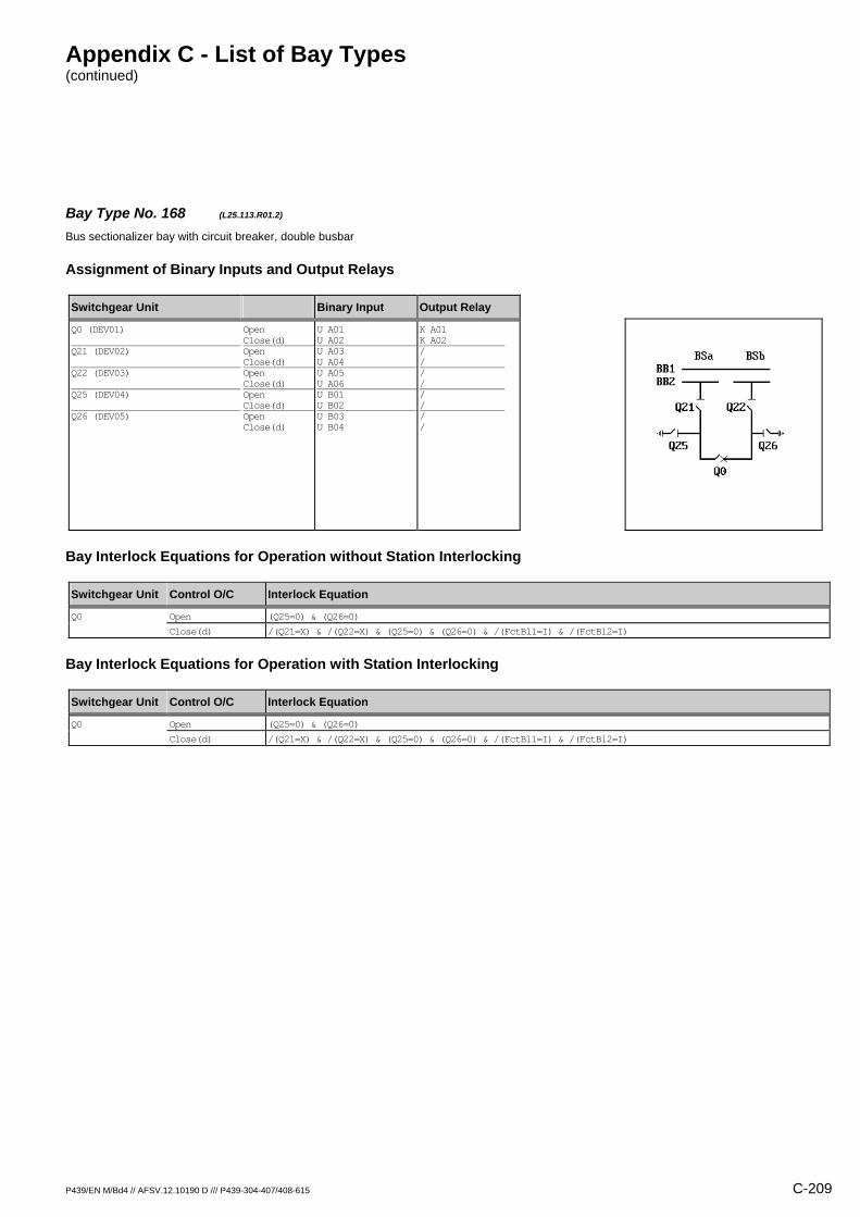
Appendix C - List of Bay Types (continued)
P439/EN M/Bd4 // AFSV.12.10190 D /// P439-304-407/408-615 C-209
Bay Type No. 168 (L25.113.R01.2) Bus sectionalizer bay with circuit breaker, double busbar
Assignment of Binary Inputs and Output Relays
Switchgear Unit Binary Input Output Relay
Q0 (DEV01) Q21 (DEV02) Q22 (DEV03) Q25 (DEV04) Q26 (DEV05)
Open Close(d) Open Close(d) Open Close(d) Open Close(d) Open Close(d)
U A01 U A02 U A03 U A04 U A05 U A06 U B01 U B02 U B03 U B04
K A01 K A02 / / / / / / / /
Bay Interlock Equations for Operation without Station Interlocking
Switchgear Unit Control O/C Interlock Equation
Q0 Open (Q25=0) & (Q26=0)
Close(d) /(Q21=X) & /(Q22=X) & (Q25=0) & (Q26=0) & /(FctBl1=I) & /(FctBl2=I)
Bay Interlock Equations for Operation with Station Interlocking
Switchgear Unit Control O/C Interlock Equation
Q0 Open (Q25=0) & (Q26=0)
Close(d) /(Q21=X) & /(Q22=X) & (Q25=0) & (Q26=0) & /(FctBl1=I) & /(FctBl2=I)

Appendix C - List of Bay Types (continued)
C-210 P439/EN M/Bd4 // AFSV.12.10190 D /// P439-304-407/408-615
Bay Type No. 230 (L25.113.R03.1) Bus sectionalizer bay with circuit breaker, double busbar
Assignment of Binary Inputs and Output Relays
Switchgear Unit Binary Input Output Relay
Q0 (DEV01) Q11 (DEV02) Q12 (DEV03) Q15 (DEV04) Q16 (DEV05)
Open Close(d) Open Close(d) Open Close(d) Open Close(d) Open Close(d)
U A01 U A02 U A03 U A04 U A05 U A06 U B01 U B02 U B03 U B04
K A01 K A02 K A03 K A04 K A05 K A06 / / / /
Bay Interlock Equations for Operation without Station Interlocking
Switchgear Unit Control O/C Interlock Equation
Q0 Open (Q15=0) & (Q16=0)
Close(d) /(Q11=X) & /(Q12=X) & (Q15=0) & (Q16=0) & /(FctBl1=I) & /(FctBl2=I)
Q11 Open (Q0=0)
Close(d) (Q0=0) & (Q15=0)
Q12 Open (Q0=0)
Close(d) (Q0=0) & (Q16=0)
Bay Interlock Equations for Operation with Station Interlocking
Switchgear Unit Control O/C Interlock Equation
Q0 Open (Q15=0) & (Q16=0)
Close(d) /(Q11=X) & /(Q12=X) & (Q15=0) & (Q16=0) & /(FctBl1=I) & /(FctBl2=I)
Q11 Open (Q0=0)
Close(d) (Q0=0) & (Q15=0)
Q12 Open (Q0=0)
Close(d) (Q0=0) & (Q16=0)
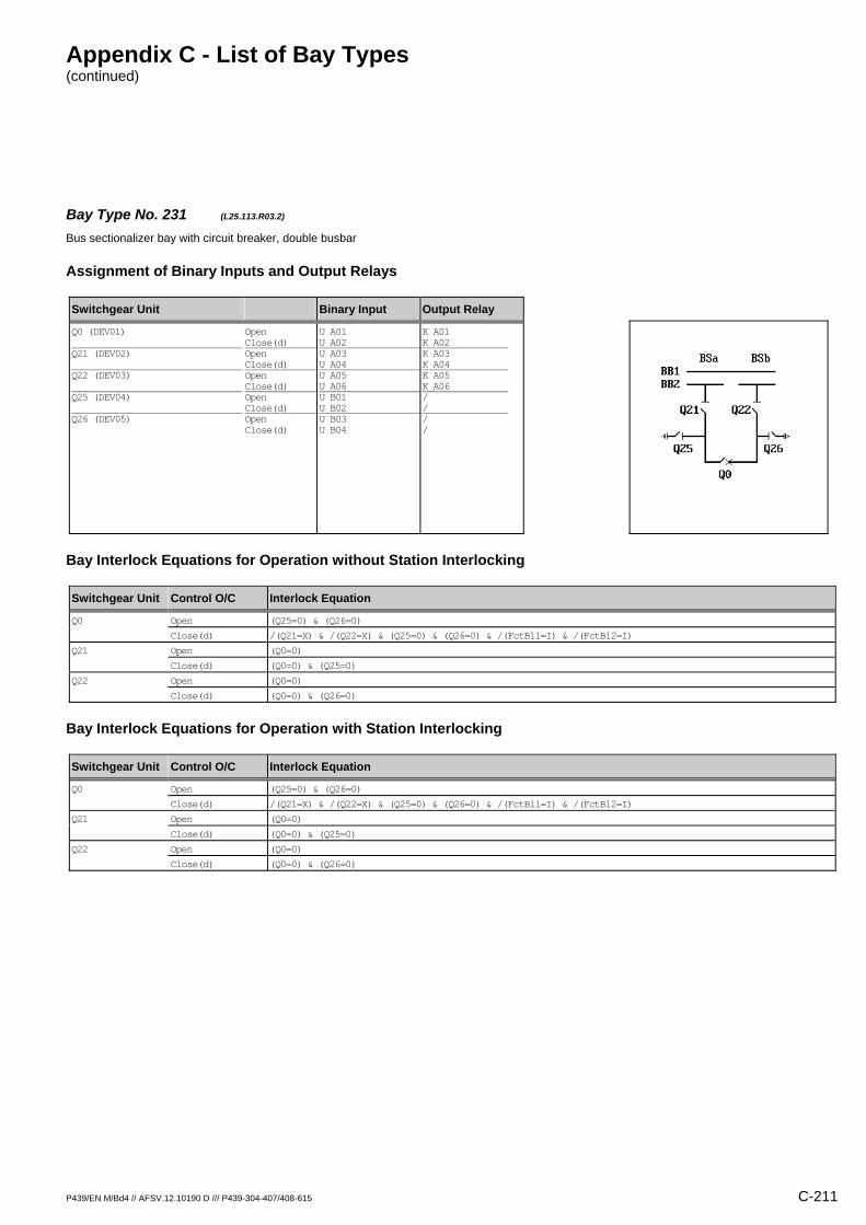
Appendix C - List of Bay Types (continued)
P439/EN M/Bd4 // AFSV.12.10190 D /// P439-304-407/408-615 C-211
Bay Type No. 231 (L25.113.R03.2) Bus sectionalizer bay with circuit breaker, double busbar
Assignment of Binary Inputs and Output Relays
Switchgear Unit Binary Input Output Relay
Q0 (DEV01) Q21 (DEV02) Q22 (DEV03) Q25 (DEV04) Q26 (DEV05)
Open Close(d) Open Close(d) Open Close(d) Open Close(d) Open Close(d)
U A01 U A02 U A03 U A04 U A05 U A06 U B01 U B02 U B03 U B04
K A01 K A02 K A03 K A04 K A05 K A06 / / / /
Bay Interlock Equations for Operation without Station Interlocking
Switchgear Unit Control O/C Interlock Equation
Q0 Open (Q25=0) & (Q26=0)
Close(d) /(Q21=X) & /(Q22=X) & (Q25=0) & (Q26=0) & /(FctBl1=I) & /(FctBl2=I)
Q21 Open (Q0=0)
Close(d) (Q0=0) & (Q25=0)
Q22 Open (Q0=0)
Close(d) (Q0=0) & (Q26=0)
Bay Interlock Equations for Operation with Station Interlocking
Switchgear Unit Control O/C Interlock Equation
Q0 Open (Q25=0) & (Q26=0)
Close(d) /(Q21=X) & /(Q22=X) & (Q25=0) & (Q26=0) & /(FctBl1=I) & /(FctBl2=I)
Q21 Open (Q0=0)
Close(d) (Q0=0) & (Q25=0)
Q22 Open (Q0=0)
Close(d) (Q0=0) & (Q26=0)
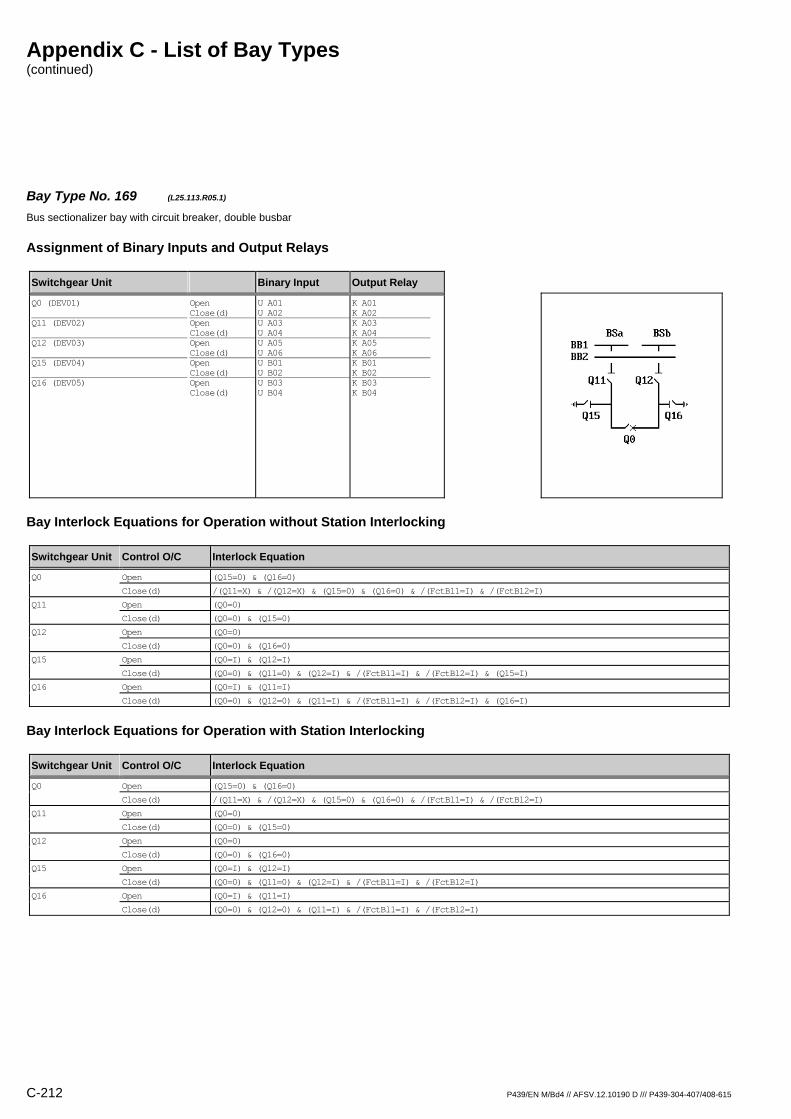
Appendix C - List of Bay Types (continued)
C-212 P439/EN M/Bd4 // AFSV.12.10190 D /// P439-304-407/408-615
Bay Type No. 169 (L25.113.R05.1) Bus sectionalizer bay with circuit breaker, double busbar
Assignment of Binary Inputs and Output Relays
Switchgear Unit Binary Input Output Relay
Q0 (DEV01) Q11 (DEV02) Q12 (DEV03) Q15 (DEV04) Q16 (DEV05)
Open Close(d) Open Close(d) Open Close(d) Open Close(d) Open Close(d)
U A01 U A02 U A03 U A04 U A05 U A06 U B01 U B02 U B03 U B04
K A01 K A02 K A03 K A04 K A05 K A06 K B01 K B02 K B03 K B04
Bay Interlock Equations for Operation without Station Interlocking
Switchgear Unit Control O/C Interlock Equation
Q0 Open (Q15=0) & (Q16=0)
Close(d) /(Q11=X) & /(Q12=X) & (Q15=0) & (Q16=0) & /(FctBl1=I) & /(FctBl2=I)
Q11 Open (Q0=0)
Close(d) (Q0=0) & (Q15=0)
Q12 Open (Q0=0)
Close(d) (Q0=0) & (Q16=0)
Q15 Open (Q0=I) & (Q12=I)
Close(d) (Q0=0) & (Q11=0) & (Q12=I) & /(FctBl1=I) & /(FctBl2=I) & (Q15=I)
Q16 Open (Q0=I) & (Q11=I)
Close(d) (Q0=0) & (Q12=0) & (Q11=I) & /(FctBl1=I) & /(FctBl2=I) & (Q16=I)
Bay Interlock Equations for Operation with Station Interlocking
Switchgear Unit Control O/C Interlock Equation
Q0 Open (Q15=0) & (Q16=0)
Close(d) /(Q11=X) & /(Q12=X) & (Q15=0) & (Q16=0) & /(FctBl1=I) & /(FctBl2=I)
Q11 Open (Q0=0)
Close(d) (Q0=0) & (Q15=0)
Q12 Open (Q0=0)
Close(d) (Q0=0) & (Q16=0)
Q15 Open (Q0=I) & (Q12=I)
Close(d) (Q0=0) & (Q11=0) & (Q12=I) & /(FctBl1=I) & /(FctBl2=I)
Q16 Open (Q0=I) & (Q11=I)
Close(d) (Q0=0) & (Q12=0) & (Q11=I) & /(FctBl1=I) & /(FctBl2=I)
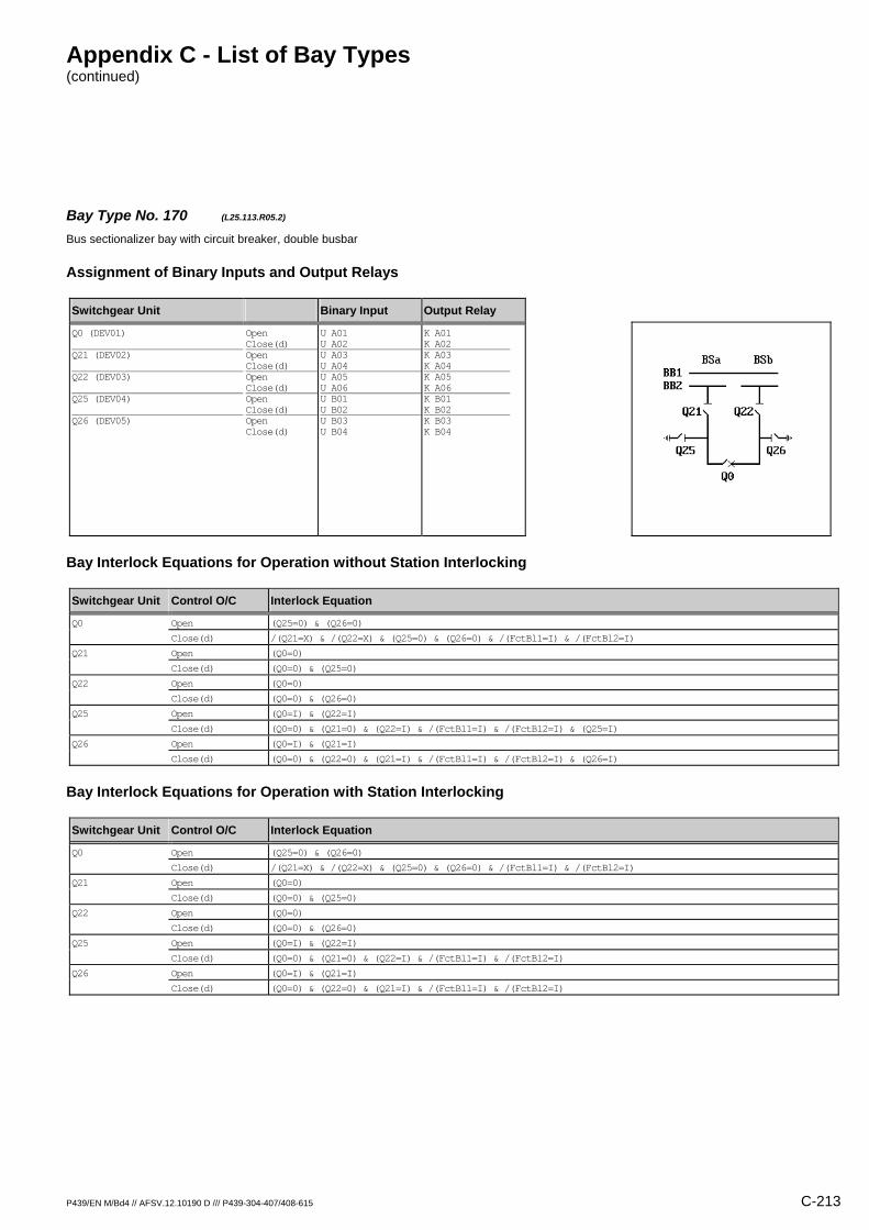
Appendix C - List of Bay Types (continued)
P439/EN M/Bd4 // AFSV.12.10190 D /// P439-304-407/408-615 C-213
Bay Type No. 170 (L25.113.R05.2) Bus sectionalizer bay with circuit breaker, double busbar
Assignment of Binary Inputs and Output Relays
Switchgear Unit Binary Input Output Relay
Q0 (DEV01) Q21 (DEV02) Q22 (DEV03) Q25 (DEV04) Q26 (DEV05)
Open Close(d) Open Close(d) Open Close(d) Open Close(d) Open Close(d)
U A01 U A02 U A03 U A04 U A05 U A06 U B01 U B02 U B03 U B04
K A01 K A02 K A03 K A04 K A05 K A06 K B01 K B02 K B03 K B04
Bay Interlock Equations for Operation without Station Interlocking
Switchgear Unit Control O/C Interlock Equation
Q0 Open (Q25=0) & (Q26=0)
Close(d) /(Q21=X) & /(Q22=X) & (Q25=0) & (Q26=0) & /(FctBl1=I) & /(FctBl2=I)
Q21 Open (Q0=0)
Close(d) (Q0=0) & (Q25=0)
Q22 Open (Q0=0)
Close(d) (Q0=0) & (Q26=0)
Q25 Open (Q0=I) & (Q22=I)
Close(d) (Q0=0) & (Q21=0) & (Q22=I) & /(FctBl1=I) & /(FctBl2=I) & (Q25=I)
Q26 Open (Q0=I) & (Q21=I)
Close(d) (Q0=0) & (Q22=0) & (Q21=I) & /(FctBl1=I) & /(FctBl2=I) & (Q26=I)
Bay Interlock Equations for Operation with Station Interlocking
Switchgear Unit Control O/C Interlock Equation
Q0 Open (Q25=0) & (Q26=0)
Close(d) /(Q21=X) & /(Q22=X) & (Q25=0) & (Q26=0) & /(FctBl1=I) & /(FctBl2=I)
Q21 Open (Q0=0)
Close(d) (Q0=0) & (Q25=0)
Q22 Open (Q0=0)
Close(d) (Q0=0) & (Q26=0)
Q25 Open (Q0=I) & (Q22=I)
Close(d) (Q0=0) & (Q21=0) & (Q22=I) & /(FctBl1=I) & /(FctBl2=I)
Q26 Open (Q0=I) & (Q21=I)
Close(d) (Q0=0) & (Q22=0) & (Q21=I) & /(FctBl1=I) & /(FctBl2=I)

Appendix C - List of Bay Types (continued)
C-214 P439/EN M/Bd4 // AFSV.12.10190 D /// P439-304-407/408-615
Bay Type No. 505 (Q21.100.R01) Bus coupler bay with circuit breaker, double busbar
Assignment of Binary Inputs and Output Relays
Switchgear Unit Binary Input Output Relay
Q0 (DEV01) X0 (DEV02)
Open Close(d) Open Close(d)
U A01 U A02 U A03 U A04
K A01 K A02 / /
Bay Interlock Equations for Operation without Station Interlocking
Switchgear Unit Control O/C Interlock Equation
Q0 Close(d) /(X0=X) & /(FctBl1=I) & /(FctBl2=I)
Bay Interlock Equations for Operation with Station Interlocking
Switchgear Unit Control O/C Interlock Equation
Q0 Close(d) /(X0=X) & /(FctBl1=I) & /(FctBl2=I)
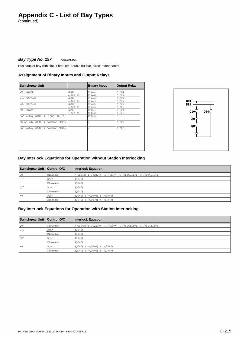
Appendix C - List of Bay Types (continued)
P439/EN M/Bd4 // AFSV.12.10190 D /// P439-304-407/408-615 C-215
Bay Type No. 197 (Q21.101.M04) Bus coupler bay with circuit breaker, double busbar, direct motor control
Assignment of Binary Inputs and Output Relays
Switchgear Unit Binary Input Output Relay
Q0 (DEV01) Q10 (DEV02) Q20 (DEV03) X0 (DEV04) Mot.relay (SIG_1: Signal S012) Shunt wd. (CMD_1: Command C011) Mot.relay (CMD_1: Command C012)
Open Close(d) Open Close(d) Open Close(d) Open Close(d)
U A01 U A02 U A03 U A04 U A05 U A06 U B01 U B02 U B06 / /
K A01 K A02 K A03 K A04 K A05 K A06 K B01 K B02 / K B05 K B06
Bay Interlock Equations for Operation without Station Interlocking
Switchgear Unit Control O/C Interlock Equation
Q0 Close(d) /(Q10=X) & /(Q20=X) & /(X0=X) & /(FctBl1=I) & /(FctBl2=I)
Q10 Open (Q0=0)
Close(d) (Q0=0)
Q20 Open (Q0=0)
Close(d) (Q0=0)
X0 Open (Q0=0) & (Q10=0) & (Q20=0)
Close(d) (Q0=0) & (Q10=0) & (Q20=0)
Bay Interlock Equations for Operation with Station Interlocking
Switchgear Unit Control O/C Interlock Equation
Q0 Close(d) /(Q10=X) & /(Q20=X) & /(X0=X) & /(FctBl1=I) & /(FctBl2=I)
Q10 Open (Q0=0)
Close(d) (Q0=0)
Q20 Open (Q0=0)
Close(d) (Q0=0)
X0 Open (Q0=0) & (Q10=0) & (Q20=0)
Close(d) (Q0=0) & (Q10=0) & (Q20=0)

Appendix C - List of Bay Types (continued)
C-216 P439/EN M/Bd4 // AFSV.12.10190 D /// P439-304-407/408-615
Bay Type No. 198 (Q21.101.R01) Bus coupler bay with circuit breaker, double busbar
Assignment of Binary Inputs and Output Relays
Switchgear Unit Binary Input Output Relay
Q0 (DEV01) Q10 (DEV02) Q20 (DEV03) X0 (DEV04)
Open Close(d) Open Close(d) Open Close(d) Open Close(d)
U A01 U A02 U A03 U A04 U A05 U A06 U B01 U B02
K A01 K A02 / / / / / /
Bay Interlock Equations for Operation without Station Interlocking
Switchgear Unit Control O/C Interlock Equation
Q0 Close(d) /(Q10=X) & /(Q20=X) & /(X0=X) & /(FctBl1=I) & /(FctBl2=I)
Bay Interlock Equations for Operation with Station Interlocking
Switchgear Unit Control O/C Interlock Equation
Q0 Close(d) /(Q10=X) & /(Q20=X) & /(X0=X) & /(FctBl1=I) & /(FctBl2=I)
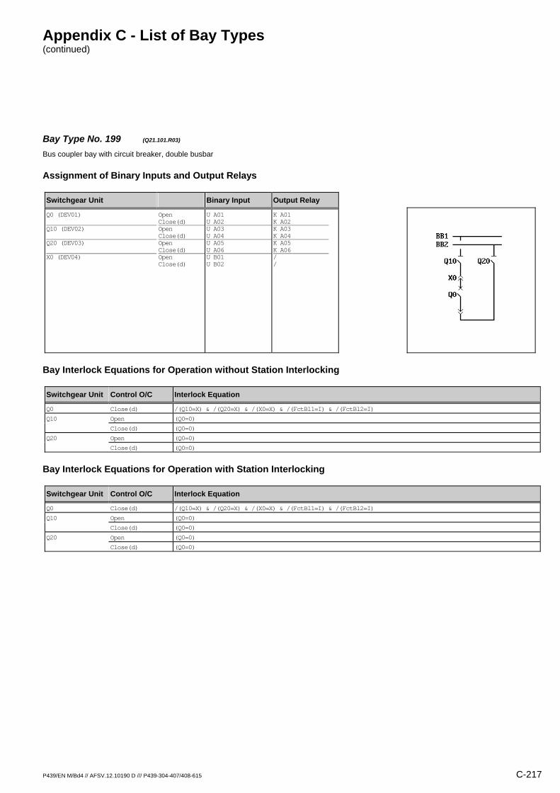
Appendix C - List of Bay Types (continued)
P439/EN M/Bd4 // AFSV.12.10190 D /// P439-304-407/408-615 C-217
Bay Type No. 199 (Q21.101.R03) Bus coupler bay with circuit breaker, double busbar
Assignment of Binary Inputs and Output Relays
Switchgear Unit Binary Input Output Relay
Q0 (DEV01) Q10 (DEV02) Q20 (DEV03) X0 (DEV04)
Open Close(d) Open Close(d) Open Close(d) Open Close(d)
U A01 U A02 U A03 U A04 U A05 U A06 U B01 U B02
K A01 K A02 K A03 K A04 K A05 K A06 / /
Bay Interlock Equations for Operation without Station Interlocking
Switchgear Unit Control O/C Interlock Equation
Q0 Close(d) /(Q10=X) & /(Q20=X) & /(X0=X) & /(FctBl1=I) & /(FctBl2=I)
Q10 Open (Q0=0)
Close(d) (Q0=0)
Q20 Open (Q0=0)
Close(d) (Q0=0)
Bay Interlock Equations for Operation with Station Interlocking
Switchgear Unit Control O/C Interlock Equation
Q0 Close(d) /(Q10=X) & /(Q20=X) & /(X0=X) & /(FctBl1=I) & /(FctBl2=I)
Q10 Open (Q0=0)
Close(d) (Q0=0)
Q20 Open (Q0=0)
Close(d) (Q0=0)

Appendix C - List of Bay Types (continued)
C-218 P439/EN M/Bd4 // AFSV.12.10190 D /// P439-304-407/408-615
Bay Type No. 200 (Q21.101.R04) Bus coupler bay with circuit breaker, double busbar
Assignment of Binary Inputs and Output Relays
Switchgear Unit Binary Input Output Relay
Q0 (DEV01) Q10 (DEV02) Q20 (DEV03) X0 (DEV04)
Open Close(d) Open Close(d) Open Close(d) Open Close(d)
U A01 U A02 U A03 U A04 U A05 U A06 U B01 U B02
K A01 K A02 K A03 K A04 K A05 K A06 K B01 K B02
Bay Interlock Equations for Operation without Station Interlocking
Switchgear Unit Control O/C Interlock Equation
Q0 Close(d) /(Q10=X) & /(Q20=X) & /(X0=X) & /(FctBl1=I) & /(FctBl2=I)
Q10 Open (Q0=0)
Close(d) (Q0=0)
Q20 Open (Q0=0)
Close(d) (Q0=0)
X0 Open (Q0=0) & (Q10=0) & (Q20=0)
Close(d) (Q0=0) & (Q10=0) & (Q20=0)
Bay Interlock Equations for Operation with Station Interlocking
Switchgear Unit Control O/C Interlock Equation
Q0 Close(d) /(Q10=X) & /(Q20=X) & /(X0=X) & /(FctBl1=I) & /(FctBl2=I)
Q10 Open (Q0=0)
Close(d) (Q0=0)
Q20 Open (Q0=0)
Close(d) (Q0=0)
X0 Open (Q0=0) & (Q10=0) & (Q20=0)
Close(d) (Q0=0) & (Q10=0) & (Q20=0)
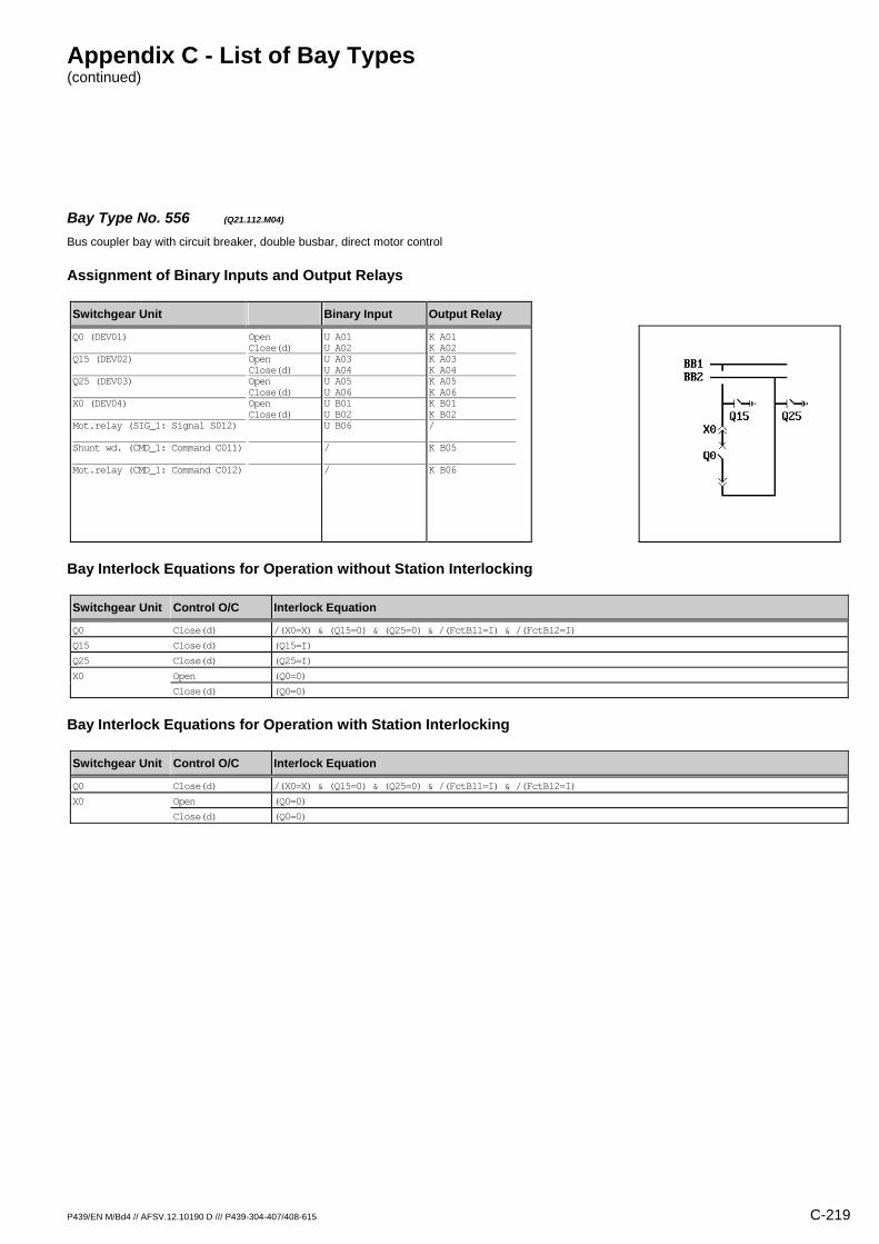
Appendix C - List of Bay Types (continued)
P439/EN M/Bd4 // AFSV.12.10190 D /// P439-304-407/408-615 C-219
Bay Type No. 556 (Q21.112.M04) Bus coupler bay with circuit breaker, double busbar, direct motor control
Assignment of Binary Inputs and Output Relays
Switchgear Unit Binary Input Output Relay
Q0 (DEV01) Q15 (DEV02) Q25 (DEV03) X0 (DEV04) Mot.relay (SIG_1: Signal S012) Shunt wd. (CMD_1: Command C011) Mot.relay (CMD_1: Command C012)
Open Close(d) Open Close(d) Open Close(d) Open Close(d)
U A01 U A02 U A03 U A04 U A05 U A06 U B01 U B02 U B06 / /
K A01 K A02 K A03 K A04 K A05 K A06 K B01 K B02 / K B05 K B06
Bay Interlock Equations for Operation without Station Interlocking
Switchgear Unit Control O/C Interlock Equation
Q0 Close(d) /(X0=X) & (Q15=0) & (Q25=0) & /(FctBl1=I) & /(FctBl2=I)
Q15 Close(d) (Q15=I)
Q25 Close(d) (Q25=I)
X0 Open (Q0=0)
Close(d) (Q0=0)
Bay Interlock Equations for Operation with Station Interlocking
Switchgear Unit Control O/C Interlock Equation
Q0 Close(d) /(X0=X) & (Q15=0) & (Q25=0) & /(FctBl1=I) & /(FctBl2=I)
X0 Open (Q0=0)
Close(d) (Q0=0)

Appendix C - List of Bay Types (continued)
C-220 P439/EN M/Bd4 // AFSV.12.10190 D /// P439-304-407/408-615
Bay Type No. 565 (Q21.112.M04.2) Bus coupler bay with circuit breaker, double busbar, direct motor control
Assignment of Binary Inputs and Output Relays
Switchgear Unit Binary Input Output Relay
Q0 (DEV01) Q15 (DEV02) Q25 (DEV03) X0 (DEV04) Mot.relay (SIG_1: Signal S012) Shunt wd. (CMD_1: Command C011) Mot.relay (CMD_1: Command C012)
Open Close(d) Open Close(d) Open Close(d) Open Close(d)
U A01 U A02 U A03 U A04 U A05 U A06 U B01 U B02 U B06 / /
K A01 K A02 K A03 K A04 K A05 K A06 K B01 K B02 / K B05 K B06
Bay Interlock Equations for Operation without Station Interlocking
Switchgear Unit Control O/C Interlock Equation
Q0 Close(d) /(X0=X) & (Q15=0) & (Q25=0) & /(FctBl1=I) & /(FctBl2=I)
Q15 Close(d) (Q15=I)
Q25 Close(d) (Q25=I)
X0 Open (Q0=0)
Close(d) (Q0=0)
Bay Interlock Equations for Operation with Station Interlocking
Switchgear Unit Control O/C Interlock Equation
Q0 Close(d) /(X0=X) & (Q15=0) & (Q25=0) & /(FctBl1=I) & /(FctBl2=I)
X0 Open (Q0=0)
Close(d) (Q0=0)

Appendix C - List of Bay Types (continued)
P439/EN M/Bd4 // AFSV.12.10190 D /// P439-304-407/408-615 C-221
Bay Type No. 201 (Q21.117.R01) Bus coupler bay with circuit breaker, double busbar
Assignment of Binary Inputs and Output Relays
Switchgear Unit Binary Input Output Relay
Q0 (DEV01) Q10 (DEV02) Q20 (DEV03) Q11 (DEV04) Q21 (DEV05) X0 (DEV06)
Open Close(d) Open Close(d) Open Close(d) Open Close(d) Open Close(d) Open Close(d)
U A01 U A02 U A03 U A04 U A05 U A06 U B01 U B02 U B03 U B04 U B05 U B06
K A01 K A02 / / / / / / / / / /
Bay Interlock Equations for Operation without Station Interlocking
Switchgear Unit Control O/C Interlock Equation
Q0 Close(d) /(Q10=X) & /(Q20=X) & /(X0=X) & /(FctBl1=I) & /(FctBl2=I)
Bay Interlock Equations for Operation with Station Interlocking
Switchgear Unit Control O/C Interlock Equation
Q0 Close(d) /(Q10=X) & /(Q20=X) & /(X0=X) & /(FctBl1=I) & /(FctBl2=I)

Appendix C - List of Bay Types (continued)
C-222 P439/EN M/Bd4 // AFSV.12.10190 D /// P439-304-407/408-615
Bay Type No. 202 (Q21.117.R05) Bus coupler bay with circuit breaker, double busbar
Assignment of Binary Inputs and Output Relays
Switchgear Unit Binary Input Output Relay
Q0 (DEV01) Q10 (DEV02) Q20 (DEV03) Q11 (DEV04) Q21 (DEV05) X0 (DEV06)
Open Close(d) Open Close(d) Open Close(d) Open Close(d) Open Close(d) Open Close(d)
U A01 U A02 U A03 U A04 U A05 U A06 U B01 U B02 U B03 U B04 U B05 U B06
K A01 K A02 K A03 K A04 K A05 K A06 K B01 K B02 K B03 K B04 / /
Bay Interlock Equations for Operation without Station Interlocking
Switchgear Unit Control O/C Interlock Equation
Q0 Close(d) /(Q10=X) & /(Q20=X) & /(X0=X) & /(FctBl1=I) & /(FctBl2=I)
Q10 Open (Q0=0)
Close(d) (Q0=0)
Q20 Open (Q0=0)
Close(d) (Q0=0)
Bay Interlock Equations for Operation with Station Interlocking
Switchgear Unit Control O/C Interlock Equation
Q0 Close(d) /(Q10=X) & /(Q20=X) & /(X0=X) & /(FctBl1=I) & /(FctBl2=I)
Q10 Open (Q0=0)
Close(d) (Q0=0)
Q20 Open (Q0=0)
Close(d) (Q0=0)

Appendix C - List of Bay Types (continued)
P439/EN M/Bd4 // AFSV.12.10190 D /// P439-304-407/408-615 C-223
Bay Type No. 203 (Q21.117.R06) Bus coupler bay with circuit breaker, double busbar
Assignment of Binary Inputs and Output Relays
Switchgear Unit Binary Input Output Relay
Q0 (DEV01) Q10 (DEV02) Q20 (DEV03) Q11 (DEV04) Q21 (DEV05) X0 (DEV06)
Open Close(d) Open Close(d) Open Close(d) Open Close(d) Open Close(d) Open Close(d)
U A01 U A02 U A03 U A04 U A05 U A06 U B01 U B02 U B03 U B04 U B05 U B06
K A01 K A02 K A03 K A04 K A05 K A06 K B01 K B02 K B03 K B04 K B05 K B06
Bay Interlock Equations for Operation without Station Interlocking
Switchgear Unit Control O/C Interlock Equation
Q0 Close(d) /(Q10=X) & /(Q20=X) & /(X0=X) & /(FctBl1=I) & /(FctBl2=I)
Q10 Open (Q0=0)
Close(d) (Q0=0)
Q20 Open (Q0=0)
Close(d) (Q0=0)
X0 Open (Q0=0) & (Q10=0) & (Q20=0)
Close(d) (Q0=0) & (Q10=0) & (Q20=0)
Bay Interlock Equations for Operation with Station Interlocking
Switchgear Unit Control O/C Interlock Equation
Q0 Close(d) /(Q10=X) & /(Q20=X) & /(X0=X) & /(FctBl1=I) & /(FctBl2=I)
Q10 Open (Q0=0)
Close(d) (Q0=0)
Q20 Open (Q0=0)
Close(d) (Q0=0)
X0 Open (Q0=0) & (Q10=0) & (Q20=0)
Close(d) (Q0=0) & (Q10=0) & (Q20=0)

Appendix C - List of Bay Types (continued)
C-224 P439/EN M/Bd4 // AFSV.12.10190 D /// P439-304-407/408-615
Bay Type No. 245 (Q21.132.R01) Bus coupler bay with circuit breaker, double busbar
Assignment of Binary Inputs and Output Relays
Switchgear Unit Binary Input Output Relay
Q0 (DEV01) X0 (DEV02) Q15 (DEV03) Q25 (DEV04)
Open Close(d) Open Close(d) Open Close(d) Open Close(d)
U A01 U A02 U A03 U A04 U A05 U A06 U B01 U B02
K A01 K A02 / / / / / /
Bay Interlock Equations for Operation without Station Interlocking
Switchgear Unit Control O/C Interlock Equation
Q0 Close(d) /(X0=X) & /(FctBl1=I) & /(FctBl2=I)
Bay Interlock Equations for Operation with Station Interlocking
Switchgear Unit Control O/C Interlock Equation
Q0 Close(d) /(X0=X) & /(FctBl1=I) & /(FctBl2=I)
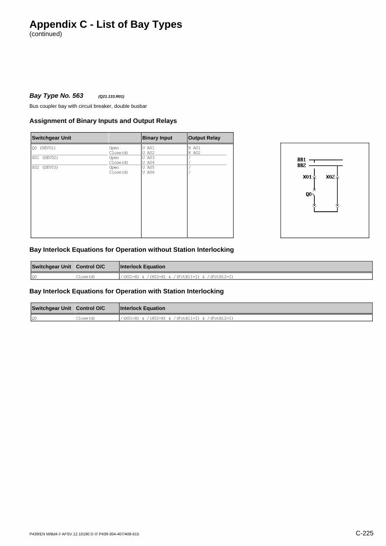
Appendix C - List of Bay Types (continued)
P439/EN M/Bd4 // AFSV.12.10190 D /// P439-304-407/408-615 C-225
Bay Type No. 563 (Q21.133.R01) Bus coupler bay with circuit breaker, double busbar
Assignment of Binary Inputs and Output Relays
Switchgear Unit Binary Input Output Relay
Q0 (DEV01) X01 (DEV02) X02 (DEV03)
Open Close(d) Open Close(d) Open Close(d)
U A01 U A02 U A03 U A04 U A05 U A06
K A01 K A02 / / / /
Bay Interlock Equations for Operation without Station Interlocking
Switchgear Unit Control O/C Interlock Equation
Q0 Close(d) /(X01=X) & /(X02=X) & /(FctBl1=I) & /(FctBl2=I)
Bay Interlock Equations for Operation with Station Interlocking
Switchgear Unit Control O/C Interlock Equation
Q0 Close(d) /(X01=X) & /(X02=X) & /(FctBl1=I) & /(FctBl2=I)

Appendix C - List of Bay Types (continued)
C-226 P439/EN M/Bd4 // AFSV.12.10190 D /// P439-304-407/408-615
Bay Type No. 204 (Q23.101.M03) Bus coupler bay with circuit breaker, double busbar, direct motor control
Assignment of Binary Inputs and Output Relays
Switchgear Unit Binary Input Output Relay
Q0 (DEV01) Q10 (DEV02) Q20 (DEV03) Mot.relay (SIG_1: Signal S012) Shunt wd. (CMD_1: Command C011) Mot.relay (CMD_1: Command C012)
Open Close(d) Open Close(d) Open Close(d)
U A01 U A02 U A03 U A04 U A05 U A06 U B06 / /
K A01 K A02 K A03 K A04 K A05 K A06 / K B05 K B06
Bay Interlock Equations for Operation without Station Interlocking
Switchgear Unit Control O/C Interlock Equation
Q0 Close(d) /(Q10=X) & /(Q20=X) & /(FctBl1=I) & /(FctBl2=I)
Q10 Open (Q0=0)
Close(d) (Q0=0)
Q20 Open (Q0=0)
Close(d) (Q0=0)
Bay Interlock Equations for Operation with Station Interlocking
Switchgear Unit Control O/C Interlock Equation
Q0 Close(d) /(Q10=X) & /(Q20=X) & /(FctBl1=I) & /(FctBl2=I)
Q10 Open (Q0=0)
Close(d) (Q0=0)
Q20 Open (Q0=0)
Close(d) (Q0=0)
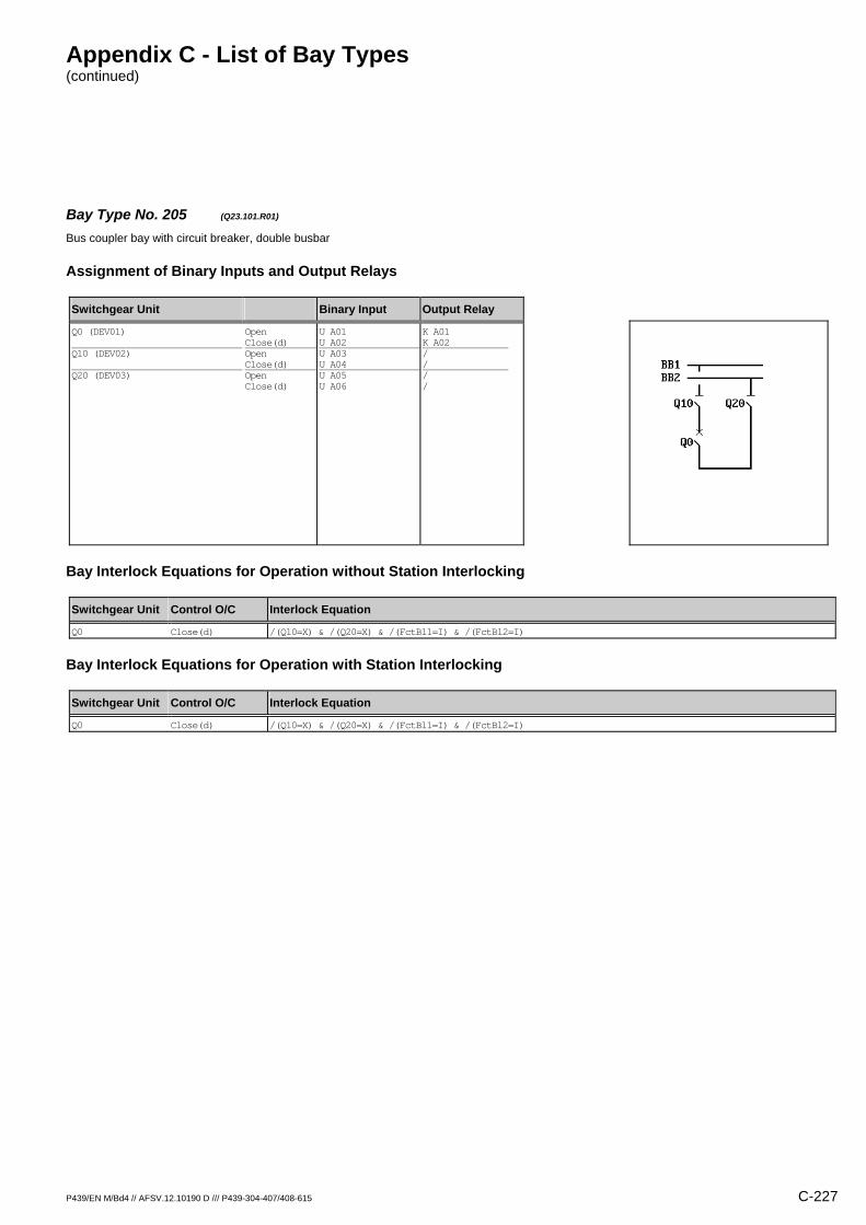
Appendix C - List of Bay Types (continued)
P439/EN M/Bd4 // AFSV.12.10190 D /// P439-304-407/408-615 C-227
Bay Type No. 205 (Q23.101.R01) Bus coupler bay with circuit breaker, double busbar
Assignment of Binary Inputs and Output Relays
Switchgear Unit Binary Input Output Relay
Q0 (DEV01) Q10 (DEV02) Q20 (DEV03)
Open Close(d) Open Close(d) Open Close(d)
U A01 U A02 U A03 U A04 U A05 U A06
K A01 K A02 / / / /
Bay Interlock Equations for Operation without Station Interlocking
Switchgear Unit Control O/C Interlock Equation
Q0 Close(d) /(Q10=X) & /(Q20=X) & /(FctBl1=I) & /(FctBl2=I)
Bay Interlock Equations for Operation with Station Interlocking
Switchgear Unit Control O/C Interlock Equation
Q0 Close(d) /(Q10=X) & /(Q20=X) & /(FctBl1=I) & /(FctBl2=I)
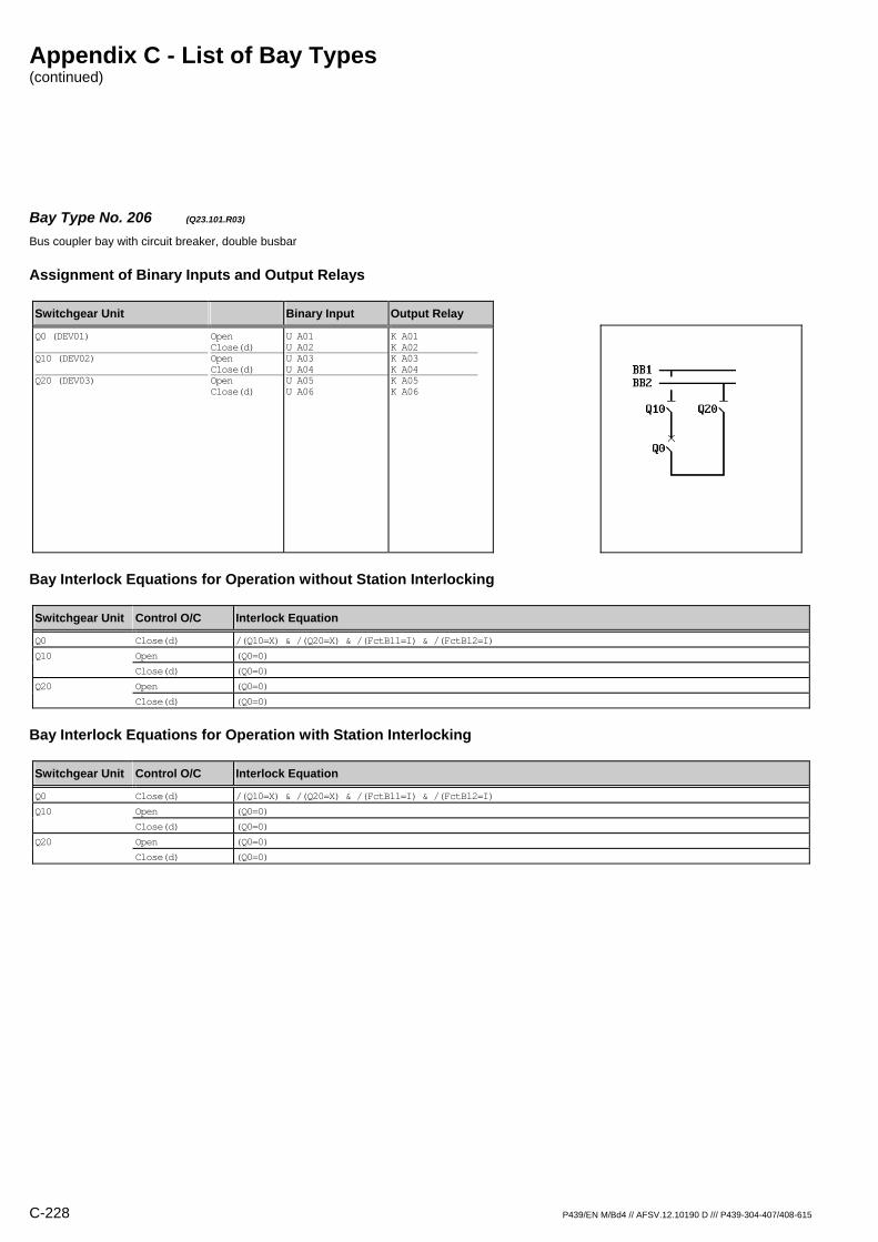
Appendix C - List of Bay Types (continued)
C-228 P439/EN M/Bd4 // AFSV.12.10190 D /// P439-304-407/408-615
Bay Type No. 206 (Q23.101.R03) Bus coupler bay with circuit breaker, double busbar
Assignment of Binary Inputs and Output Relays
Switchgear Unit Binary Input Output Relay
Q0 (DEV01) Q10 (DEV02) Q20 (DEV03)
Open Close(d) Open Close(d) Open Close(d)
U A01 U A02 U A03 U A04 U A05 U A06
K A01 K A02 K A03 K A04 K A05 K A06
Bay Interlock Equations for Operation without Station Interlocking
Switchgear Unit Control O/C Interlock Equation
Q0 Close(d) /(Q10=X) & /(Q20=X) & /(FctBl1=I) & /(FctBl2=I)
Q10 Open (Q0=0)
Close(d) (Q0=0)
Q20 Open (Q0=0)
Close(d) (Q0=0)
Bay Interlock Equations for Operation with Station Interlocking
Switchgear Unit Control O/C Interlock Equation
Q0 Close(d) /(Q10=X) & /(Q20=X) & /(FctBl1=I) & /(FctBl2=I)
Q10 Open (Q0=0)
Close(d) (Q0=0)
Q20 Open (Q0=0)
Close(d) (Q0=0)

Appendix C - List of Bay Types (continued)
P439/EN M/Bd4 // AFSV.12.10190 D /// P439-304-407/408-615 C-229
Bay Type No. 207 (Q23.117.R01) Bus coupler bay with circuit breaker, double busbar
Assignment of Binary Inputs and Output Relays
Switchgear Unit Binary Input Output Relay
Q0 (DEV01) Q10 (DEV02) Q20 (DEV03) Q11 (DEV04) Q21 (DEV05)
Open Close(d) Open Close(d) Open Close(d) Open Close(d) Open Close(d)
U A01 U A02 U A03 U A04 U A05 U A06 U B01 U B02 U B03 U B04
K A01 K A02 / / / / / / / /
Bay Interlock Equations for Operation without Station Interlocking
Switchgear Unit Control O/C Interlock Equation
Q0 Close(d) /(Q10=X) & /(Q20=X) & /(FctBl1=I) & /(FctBl2=I)
Bay Interlock Equations for Operation with Station Interlocking
Switchgear Unit Control O/C Interlock Equation
Q0 Close(d) /(Q10=X) & /(Q20=X) & /(FctBl1=I) & /(FctBl2=I)
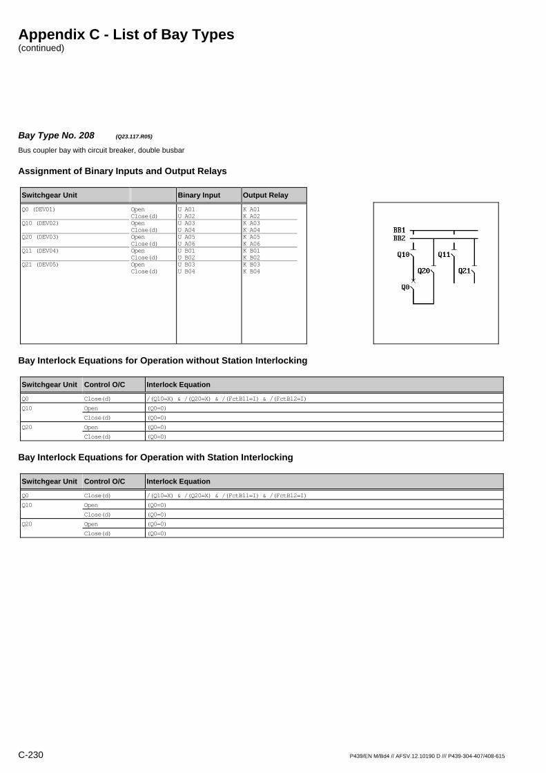
Appendix C - List of Bay Types (continued)
C-230 P439/EN M/Bd4 // AFSV.12.10190 D /// P439-304-407/408-615
Bay Type No. 208 (Q23.117.R05) Bus coupler bay with circuit breaker, double busbar
Assignment of Binary Inputs and Output Relays
Switchgear Unit Binary Input Output Relay
Q0 (DEV01) Q10 (DEV02) Q20 (DEV03) Q11 (DEV04) Q21 (DEV05)
Open Close(d) Open Close(d) Open Close(d) Open Close(d) Open Close(d)
U A01 U A02 U A03 U A04 U A05 U A06 U B01 U B02 U B03 U B04
K A01 K A02 K A03 K A04 K A05 K A06 K B01 K B02 K B03 K B04
Bay Interlock Equations for Operation without Station Interlocking
Switchgear Unit Control O/C Interlock Equation
Q0 Close(d) /(Q10=X) & /(Q20=X) & /(FctBl1=I) & /(FctBl2=I)
Q10 Open (Q0=0)
Close(d) (Q0=0)
Q20 Open (Q0=0)
Close(d) (Q0=0)
Bay Interlock Equations for Operation with Station Interlocking
Switchgear Unit Control O/C Interlock Equation
Q0 Close(d) /(Q10=X) & /(Q20=X) & /(FctBl1=I) & /(FctBl2=I)
Q10 Open (Q0=0)
Close(d) (Q0=0)
Q20 Open (Q0=0)
Close(d) (Q0=0)
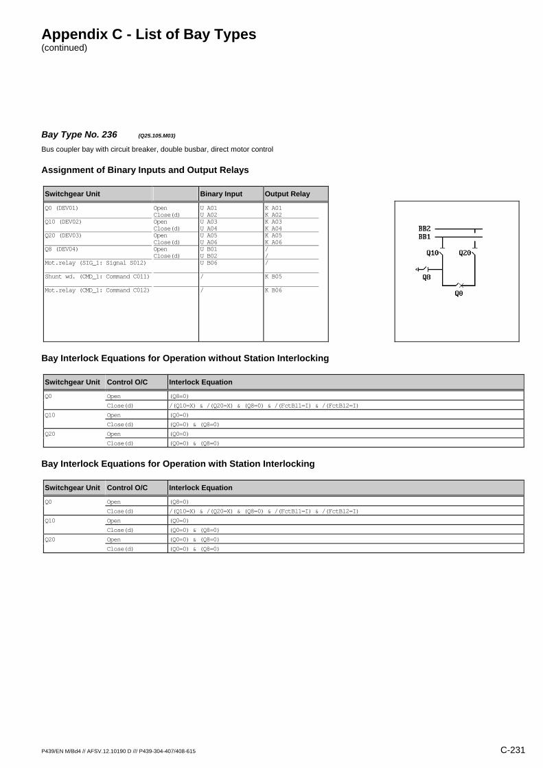
Appendix C - List of Bay Types (continued)
P439/EN M/Bd4 // AFSV.12.10190 D /// P439-304-407/408-615 C-231
Bay Type No. 236 (Q25.105.M03) Bus coupler bay with circuit breaker, double busbar, direct motor control
Assignment of Binary Inputs and Output Relays
Switchgear Unit Binary Input Output Relay
Q0 (DEV01) Q10 (DEV02) Q20 (DEV03) Q8 (DEV04) Mot.relay (SIG_1: Signal S012) Shunt wd. (CMD_1: Command C011) Mot.relay (CMD_1: Command C012)
Open Close(d) Open Close(d) Open Close(d) Open Close(d)
U A01 U A02 U A03 U A04 U A05 U A06 U B01 U B02 U B06 / /
K A01 K A02 K A03 K A04 K A05 K A06 / / / K B05 K B06
Bay Interlock Equations for Operation without Station Interlocking
Switchgear Unit Control O/C Interlock Equation
Q0 Open (Q8=0)
Close(d) /(Q10=X) & /(Q20=X) & (Q8=0) & /(FctBl1=I) & /(FctBl2=I)
Q10 Open (Q0=0)
Close(d) (Q0=0) & (Q8=0)
Q20 Open (Q0=0)
Close(d) (Q0=0) & (Q8=0)
Bay Interlock Equations for Operation with Station Interlocking
Switchgear Unit Control O/C Interlock Equation
Q0 Open (Q8=0)
Close(d) /(Q10=X) & /(Q20=X) & (Q8=0) & /(FctBl1=I) & /(FctBl2=I)
Q10 Open (Q0=0)
Close(d) (Q0=0) & (Q8=0)
Q20 Open (Q0=0) & (Q8=0)
Close(d) (Q0=0) & (Q8=0)
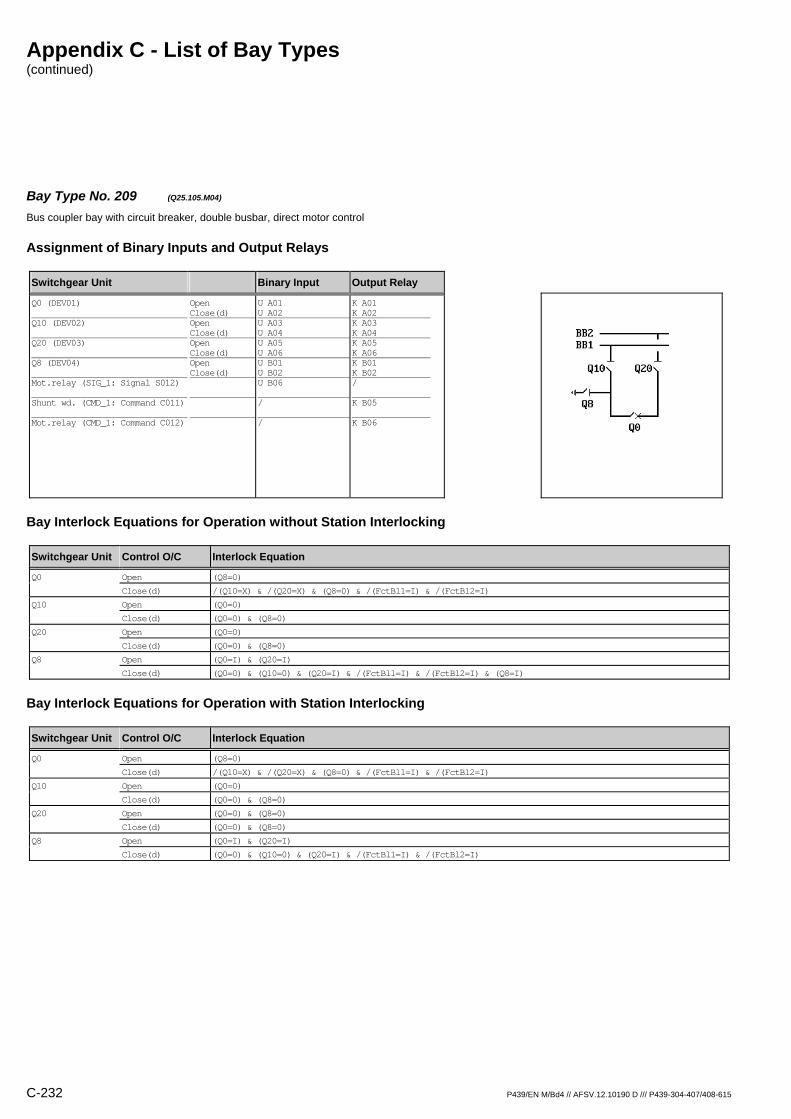
Appendix C - List of Bay Types (continued)
C-232 P439/EN M/Bd4 // AFSV.12.10190 D /// P439-304-407/408-615
Bay Type No. 209 (Q25.105.M04) Bus coupler bay with circuit breaker, double busbar, direct motor control
Assignment of Binary Inputs and Output Relays
Switchgear Unit Binary Input Output Relay
Q0 (DEV01) Q10 (DEV02) Q20 (DEV03) Q8 (DEV04) Mot.relay (SIG_1: Signal S012) Shunt wd. (CMD_1: Command C011) Mot.relay (CMD_1: Command C012)
Open Close(d) Open Close(d) Open Close(d) Open Close(d)
U A01 U A02 U A03 U A04 U A05 U A06 U B01 U B02 U B06 / /
K A01 K A02 K A03 K A04 K A05 K A06 K B01 K B02 / K B05 K B06
Bay Interlock Equations for Operation without Station Interlocking
Switchgear Unit Control O/C Interlock Equation
Q0 Open (Q8=0)
Close(d) /(Q10=X) & /(Q20=X) & (Q8=0) & /(FctBl1=I) & /(FctBl2=I)
Q10 Open (Q0=0)
Close(d) (Q0=0) & (Q8=0)
Q20 Open (Q0=0)
Close(d) (Q0=0) & (Q8=0)
Q8 Open (Q0=I) & (Q20=I)
Close(d) (Q0=0) & (Q10=0) & (Q20=I) & /(FctBl1=I) & /(FctBl2=I) & (Q8=I)
Bay Interlock Equations for Operation with Station Interlocking
Switchgear Unit Control O/C Interlock Equation
Q0 Open (Q8=0)
Close(d) /(Q10=X) & /(Q20=X) & (Q8=0) & /(FctBl1=I) & /(FctBl2=I)
Q10 Open (Q0=0)
Close(d) (Q0=0) & (Q8=0)
Q20 Open (Q0=0) & (Q8=0)
Close(d) (Q0=0) & (Q8=0)
Q8 Open (Q0=I) & (Q20=I)
Close(d) (Q0=0) & (Q10=0) & (Q20=I) & /(FctBl1=I) & /(FctBl2=I)

Appendix C - List of Bay Types (continued)
P439/EN M/Bd4 // AFSV.12.10190 D /// P439-304-407/408-615 C-233
Bay Type No. 210 (Q25.105.R01) Bus coupler bay with circuit breaker, double busbar
Assignment of Binary Inputs and Output Relays
Switchgear Unit Binary Input Output Relay
Q0 (DEV01) Q10 (DEV02) Q20 (DEV03) Q8 (DEV04)
Open Close(d) Open Close(d) Open Close(d) Open Close(d)
U A01 U A02 U A03 U A04 U A05 U A06 U B01 U B02
K A01 K A02 / / / / / /
Bay Interlock Equations for Operation without Station Interlocking
Switchgear Unit Control O/C Interlock Equation
Q0 Open (Q8=0)
Close(d) /(Q10=X) & /(Q20=X) & (Q8=0) & /(FctBl1=I) & /(FctBl2=I)
Bay Interlock Equations for Operation with Station Interlocking
Switchgear Unit Control O/C Interlock Equation
Q0 Open (Q8=0)
Close(d) /(Q10=X) & /(Q20=X) & (Q8=0) & /(FctBl1=I) & /(FctBl2=I)
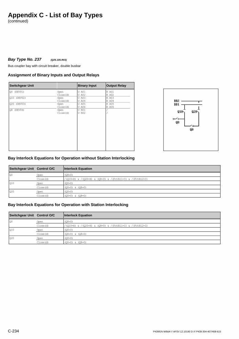
Appendix C - List of Bay Types (continued)
C-234 P439/EN M/Bd4 // AFSV.12.10190 D /// P439-304-407/408-615
Bay Type No. 237 (Q25.105.R03) Bus coupler bay with circuit breaker, double busbar
Assignment of Binary Inputs and Output Relays
Switchgear Unit Binary Input Output Relay
Q0 (DEV01) Q10 (DEV02) Q20 (DEV03) Q8 (DEV04)
Open Close(d) Open Close(d) Open Close(d) Open Close(d)
U A01 U A02 U A03 U A04 U A05 U A06 U B01 U B02
K A01 K A02 K A03 K A04 K A05 K A06 / /
Bay Interlock Equations for Operation without Station Interlocking
Switchgear Unit Control O/C Interlock Equation
Q0 Open (Q8=0)
Close(d) /(Q10=X) & /(Q20=X) & (Q8=0) & /(FctBl1=I) & /(FctBl2=I)
Q10 Open (Q0=0)
Close(d) (Q0=0) & (Q8=0)
Q20 Open (Q0=0)
Close(d) (Q0=0) & (Q8=0)
Bay Interlock Equations for Operation with Station Interlocking
Switchgear Unit Control O/C Interlock Equation
Q0 Open (Q8=0)
Close(d) /(Q10=X) & /(Q20=X) & (Q8=0) & /(FctBl1=I) & /(FctBl2=I)
Q10 Open (Q0=0)
Close(d) (Q0=0) & (Q8=0)
Q20 Open (Q0=0)
Close(d) (Q0=0) & (Q8=0)
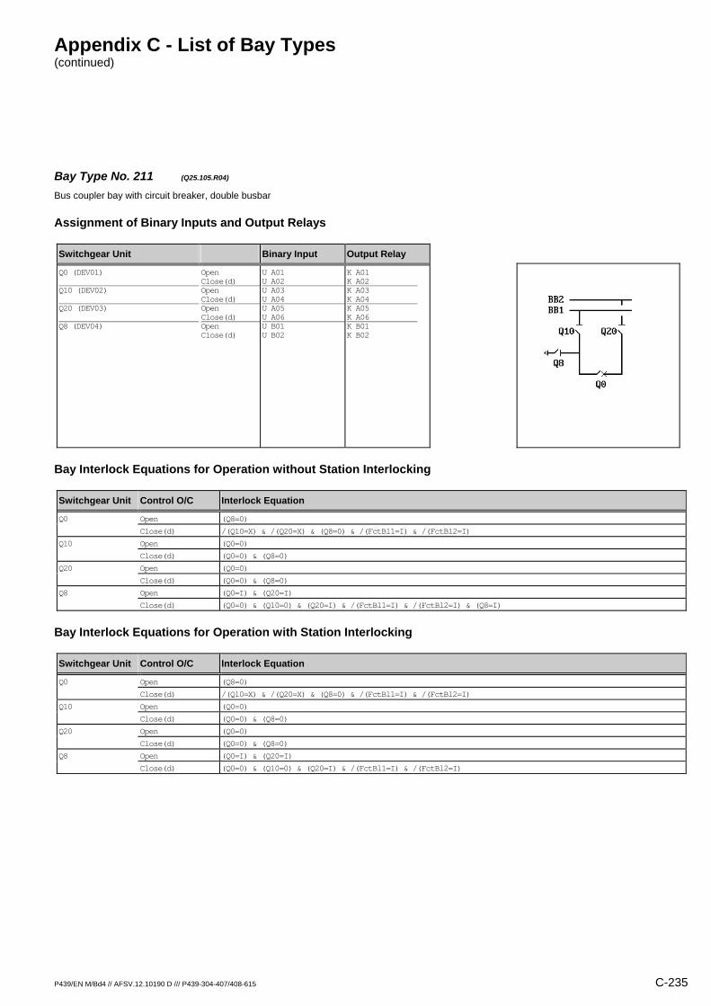
Appendix C - List of Bay Types (continued)
P439/EN M/Bd4 // AFSV.12.10190 D /// P439-304-407/408-615 C-235
Bay Type No. 211 (Q25.105.R04) Bus coupler bay with circuit breaker, double busbar
Assignment of Binary Inputs and Output Relays
Switchgear Unit Binary Input Output Relay
Q0 (DEV01) Q10 (DEV02) Q20 (DEV03) Q8 (DEV04)
Open Close(d) Open Close(d) Open Close(d) Open Close(d)
U A01 U A02 U A03 U A04 U A05 U A06 U B01 U B02
K A01 K A02 K A03 K A04 K A05 K A06 K B01 K B02
Bay Interlock Equations for Operation without Station Interlocking
Switchgear Unit Control O/C Interlock Equation
Q0 Open (Q8=0)
Close(d) /(Q10=X) & /(Q20=X) & (Q8=0) & /(FctBl1=I) & /(FctBl2=I)
Q10 Open (Q0=0)
Close(d) (Q0=0) & (Q8=0)
Q20 Open (Q0=0)
Close(d) (Q0=0) & (Q8=0)
Q8 Open (Q0=I) & (Q20=I)
Close(d) (Q0=0) & (Q10=0) & (Q20=I) & /(FctBl1=I) & /(FctBl2=I) & (Q8=I)
Bay Interlock Equations for Operation with Station Interlocking
Switchgear Unit Control O/C Interlock Equation
Q0 Open (Q8=0)
Close(d) /(Q10=X) & /(Q20=X) & (Q8=0) & /(FctBl1=I) & /(FctBl2=I)
Q10 Open (Q0=0)
Close(d) (Q0=0) & (Q8=0)
Q20 Open (Q0=0)
Close(d) (Q0=0) & (Q8=0)
Q8 Open (Q0=I) & (Q20=I)
Close(d) (Q0=0) & (Q10=0) & (Q20=I) & /(FctBl1=I) & /(FctBl2=I)

Appendix C - List of Bay Types (continued)
C-236 P439/EN M/Bd4 // AFSV.12.10190 D /// P439-304-407/408-615
Bay Type No. 238 (Q25.109.M03) Bus coupler bay with circuit breaker, double busbar, direct motor control
Assignment of Binary Inputs and Output Relays
Switchgear Unit Binary Input Output Relay
Q0 (DEV01) Q10 (DEV02) Q20 (DEV03) Q8 (DEV04) Mot.relay (SIG_1: Signal S012) Shunt wd. (CMD_1: Command C011) Mot.relay (CMD_1: Command C012)
Open Close(d) Open Close(d) Open Close(d) Open Close(d)
U A01 U A02 U A03 U A04 U A05 U A06 U B01 U B02 U B06 / /
K A01 K A02 K A03 K A04 K A05 K A06 / / / K B05 K B06
Bay Interlock Equations for Operation without Station Interlocking
Switchgear Unit Control O/C Interlock Equation
Q0 Open (Q8=0)
Close(d) /(Q10=X) & /(Q20=X) & (Q8=0) & /(FctBl1=I) & /(FctBl2=I)
Q10 Open (Q0=0)
Close(d) (Q0=0) & (Q8=0)
Q20 Open (Q0=0)
Close(d) (Q0=0) & (Q8=0)
Bay Interlock Equations for Operation with Station Interlocking
Switchgear Unit Control O/C Interlock Equation
Q0 Open (Q8=0)
Close(d) /(Q10=X) & /(Q20=X) & (Q8=0) & /(FctBl1=I) & /(FctBl2=I)
Q10 Open (Q0=0)
Close(d) (Q0=0) & (Q8=0)
Q20 Open (Q0=0)
Close(d) (Q0=0) & (Q8=0)
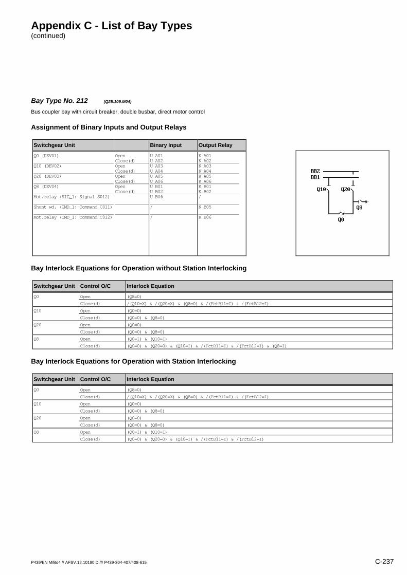
Appendix C - List of Bay Types (continued)
P439/EN M/Bd4 // AFSV.12.10190 D /// P439-304-407/408-615 C-237
Bay Type No. 212 (Q25.109.M04) Bus coupler bay with circuit breaker, double busbar, direct motor control
Assignment of Binary Inputs and Output Relays
Switchgear Unit Binary Input Output Relay
Q0 (DEV01) Q10 (DEV02) Q20 (DEV03) Q8 (DEV04) Mot.relay (SIG_1: Signal S012) Shunt wd. (CMD_1: Command C011) Mot.relay (CMD_1: Command C012)
Open Close(d) Open Close(d) Open Close(d) Open Close(d)
U A01 U A02 U A03 U A04 U A05 U A06 U B01 U B02 U B06 / /
K A01 K A02 K A03 K A04 K A05 K A06 K B01 K B02 / K B05 K B06
Bay Interlock Equations for Operation without Station Interlocking
Switchgear Unit Control O/C Interlock Equation
Q0 Open (Q8=0)
Close(d) /(Q10=X) & /(Q20=X) & (Q8=0) & /(FctBl1=I) & /(FctBl2=I)
Q10 Open (Q0=0)
Close(d) (Q0=0) & (Q8=0)
Q20 Open (Q0=0)
Close(d) (Q0=0) & (Q8=0)
Q8 Open (Q0=I) & (Q10=I)
Close(d) (Q0=0) & (Q20=0) & (Q10=I) & /(FctBl1=I) & /(FctBl2=I) & (Q8=I)
Bay Interlock Equations for Operation with Station Interlocking
Switchgear Unit Control O/C Interlock Equation
Q0 Open (Q8=0)
Close(d) /(Q10=X) & /(Q20=X) & (Q8=0) & /(FctBl1=I) & /(FctBl2=I)
Q10 Open (Q0=0)
Close(d) (Q0=0) & (Q8=0)
Q20 Open (Q0=0)
Close(d) (Q0=0) & (Q8=0)
Q8 Open (Q0=I) & (Q10=I)
Close(d) (Q0=0) & (Q20=0) & (Q10=I) & /(FctBl1=I) & /(FctBl2=I)
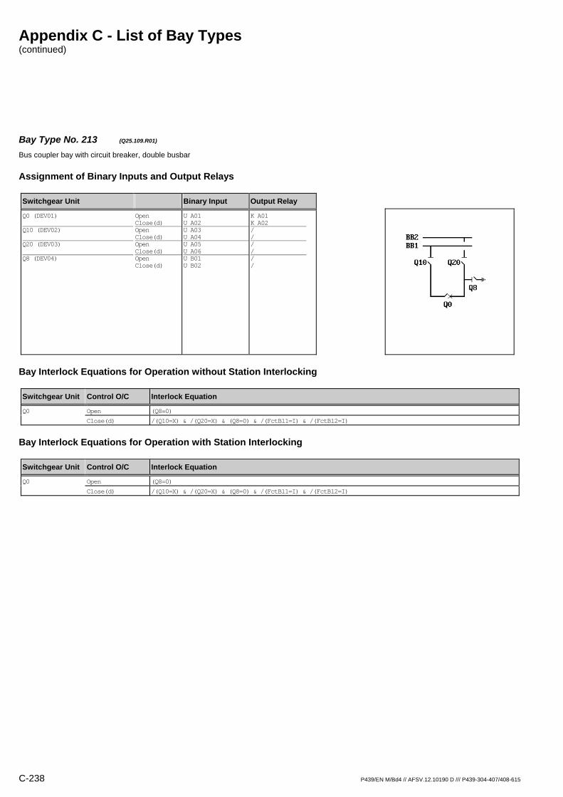
Appendix C - List of Bay Types (continued)
C-238 P439/EN M/Bd4 // AFSV.12.10190 D /// P439-304-407/408-615
Bay Type No. 213 (Q25.109.R01) Bus coupler bay with circuit breaker, double busbar
Assignment of Binary Inputs and Output Relays
Switchgear Unit Binary Input Output Relay
Q0 (DEV01) Q10 (DEV02) Q20 (DEV03) Q8 (DEV04)
Open Close(d) Open Close(d) Open Close(d) Open Close(d)
U A01 U A02 U A03 U A04 U A05 U A06 U B01 U B02
K A01 K A02 / / / / / /
Bay Interlock Equations for Operation without Station Interlocking
Switchgear Unit Control O/C Interlock Equation
Q0 Open (Q8=0)
Close(d) /(Q10=X) & /(Q20=X) & (Q8=0) & /(FctBl1=I) & /(FctBl2=I)
Bay Interlock Equations for Operation with Station Interlocking
Switchgear Unit Control O/C Interlock Equation
Q0 Open (Q8=0)
Close(d) /(Q10=X) & /(Q20=X) & (Q8=0) & /(FctBl1=I) & /(FctBl2=I)
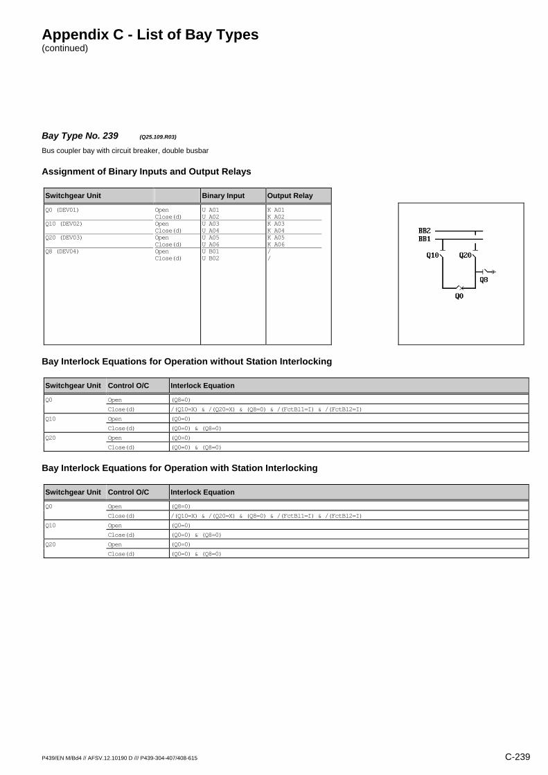
Appendix C - List of Bay Types (continued)
P439/EN M/Bd4 // AFSV.12.10190 D /// P439-304-407/408-615 C-239
Bay Type No. 239 (Q25.109.R03) Bus coupler bay with circuit breaker, double busbar
Assignment of Binary Inputs and Output Relays
Switchgear Unit Binary Input Output Relay
Q0 (DEV01) Q10 (DEV02) Q20 (DEV03) Q8 (DEV04)
Open Close(d) Open Close(d) Open Close(d) Open Close(d)
U A01 U A02 U A03 U A04 U A05 U A06 U B01 U B02
K A01 K A02 K A03 K A04 K A05 K A06 / /
Bay Interlock Equations for Operation without Station Interlocking
Switchgear Unit Control O/C Interlock Equation
Q0 Open (Q8=0)
Close(d) /(Q10=X) & /(Q20=X) & (Q8=0) & /(FctBl1=I) & /(FctBl2=I)
Q10 Open (Q0=0)
Close(d) (Q0=0) & (Q8=0)
Q20 Open (Q0=0)
Close(d) (Q0=0) & (Q8=0)
Bay Interlock Equations for Operation with Station Interlocking
Switchgear Unit Control O/C Interlock Equation
Q0 Open (Q8=0)
Close(d) /(Q10=X) & /(Q20=X) & (Q8=0) & /(FctBl1=I) & /(FctBl2=I)
Q10 Open (Q0=0)
Close(d) (Q0=0) & (Q8=0)
Q20 Open (Q0=0)
Close(d) (Q0=0) & (Q8=0)
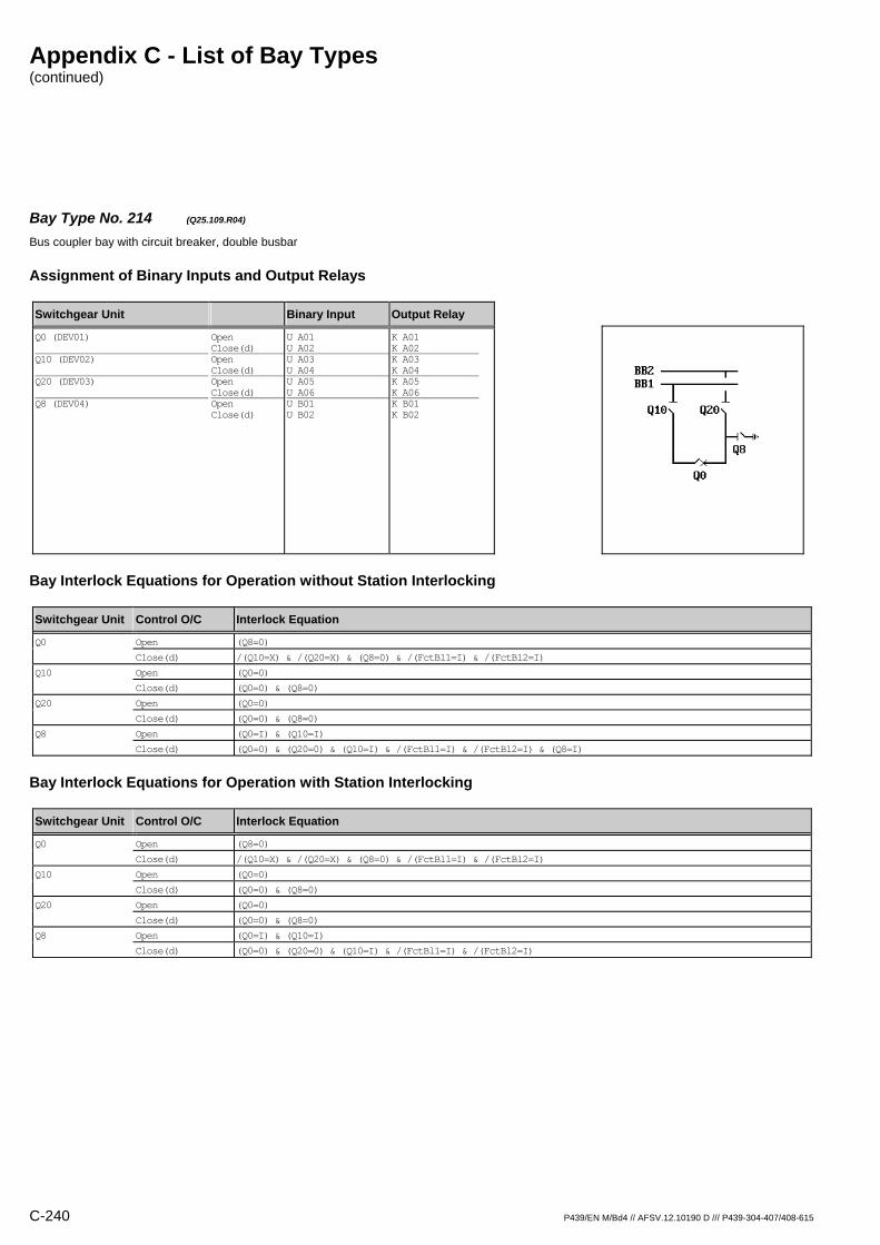
Appendix C - List of Bay Types (continued)
C-240 P439/EN M/Bd4 // AFSV.12.10190 D /// P439-304-407/408-615
Bay Type No. 214 (Q25.109.R04) Bus coupler bay with circuit breaker, double busbar
Assignment of Binary Inputs and Output Relays
Switchgear Unit Binary Input Output Relay
Q0 (DEV01) Q10 (DEV02) Q20 (DEV03) Q8 (DEV04)
Open Close(d) Open Close(d) Open Close(d) Open Close(d)
U A01 U A02 U A03 U A04 U A05 U A06 U B01 U B02
K A01 K A02 K A03 K A04 K A05 K A06 K B01 K B02
Bay Interlock Equations for Operation without Station Interlocking
Switchgear Unit Control O/C Interlock Equation
Q0 Open (Q8=0)
Close(d) /(Q10=X) & /(Q20=X) & (Q8=0) & /(FctBl1=I) & /(FctBl2=I)
Q10 Open (Q0=0)
Close(d) (Q0=0) & (Q8=0)
Q20 Open (Q0=0)
Close(d) (Q0=0) & (Q8=0)
Q8 Open (Q0=I) & (Q10=I)
Close(d) (Q0=0) & (Q20=0) & (Q10=I) & /(FctBl1=I) & /(FctBl2=I) & (Q8=I)
Bay Interlock Equations for Operation with Station Interlocking
Switchgear Unit Control O/C Interlock Equation
Q0 Open (Q8=0)
Close(d) /(Q10=X) & /(Q20=X) & (Q8=0) & /(FctBl1=I) & /(FctBl2=I)
Q10 Open (Q0=0)
Close(d) (Q0=0) & (Q8=0)
Q20 Open (Q0=0)
Close(d) (Q0=0) & (Q8=0)
Q8 Open (Q0=I) & (Q10=I)
Close(d) (Q0=0) & (Q20=0) & (Q10=I) & /(FctBl1=I) & /(FctBl2=I)
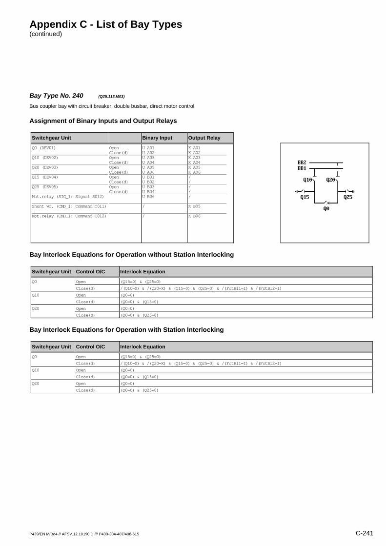
Appendix C - List of Bay Types (continued)
P439/EN M/Bd4 // AFSV.12.10190 D /// P439-304-407/408-615 C-241
Bay Type No. 240 (Q25.113.M03) Bus coupler bay with circuit breaker, double busbar, direct motor control
Assignment of Binary Inputs and Output Relays
Switchgear Unit Binary Input Output Relay
Q0 (DEV01) Q10 (DEV02) Q20 (DEV03) Q15 (DEV04) Q25 (DEV05) Mot.relay (SIG_1: Signal S012) Shunt wd. (CMD_1: Command C011) Mot.relay (CMD_1: Command C012)
Open Close(d) Open Close(d) Open Close(d) Open Close(d) Open Close(d)
U A01 U A02 U A03 U A04 U A05 U A06 U B01 U B02 U B03 U B04 U B06 / /
K A01 K A02 K A03 K A04 K A05 K A06 / / / / / K B05 K B06
Bay Interlock Equations for Operation without Station Interlocking
Switchgear Unit Control O/C Interlock Equation
Q0 Open (Q15=0) & (Q25=0)
Close(d) /(Q10=X) & /(Q20=X) & (Q15=0) & (Q25=0) & /(FctBl1=I) & /(FctBl2=I)
Q10 Open (Q0=0)
Close(d) (Q0=0) & (Q15=0)
Q20 Open (Q0=0)
Close(d) (Q0=0) & (Q25=0)
Bay Interlock Equations for Operation with Station Interlocking
Switchgear Unit Control O/C Interlock Equation
Q0 Open (Q15=0) & (Q25=0)
Close(d) /(Q10=X) & /(Q20=X) & (Q15=0) & (Q25=0) & /(FctBl1=I) & /(FctBl2=I)
Q10 Open (Q0=0)
Close(d) (Q0=0) & (Q15=0)
Q20 Open (Q0=0)
Close(d) (Q0=0) & (Q25=0)
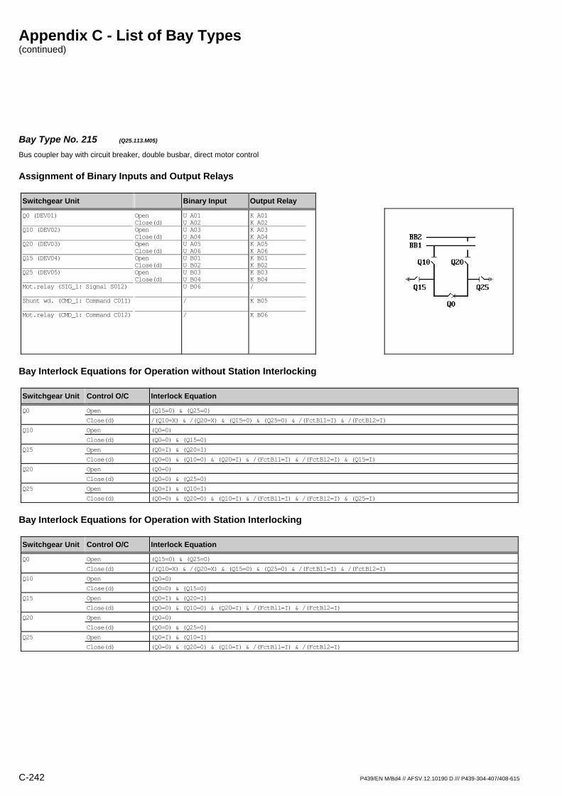
Appendix C - List of Bay Types (continued)
C-242 P439/EN M/Bd4 // AFSV.12.10190 D /// P439-304-407/408-615
Bay Type No. 215 (Q25.113.M05) Bus coupler bay with circuit breaker, double busbar, direct motor control
Assignment of Binary Inputs and Output Relays
Switchgear Unit Binary Input Output Relay
Q0 (DEV01) Q10 (DEV02) Q20 (DEV03) Q15 (DEV04) Q25 (DEV05) Mot.relay (SIG_1: Signal S012) Shunt wd. (CMD_1: Command C011) Mot.relay (CMD_1: Command C012)
Open Close(d) Open Close(d) Open Close(d) Open Close(d) Open Close(d)
U A01 U A02 U A03 U A04 U A05 U A06 U B01 U B02 U B03 U B04 U B06 / /
K A01 K A02 K A03 K A04 K A05 K A06 K B01 K B02 K B03 K B04 / K B05 K B06
Bay Interlock Equations for Operation without Station Interlocking
Switchgear Unit Control O/C Interlock Equation
Q0 Open (Q15=0) & (Q25=0)
Close(d) /(Q10=X) & /(Q20=X) & (Q15=0) & (Q25=0) & /(FctBl1=I) & /(FctBl2=I)
Q10 Open (Q0=0)
Close(d) (Q0=0) & (Q15=0)
Q15 Open (Q0=I) & (Q20=I)
Close(d) (Q0=0) & (Q10=0) & (Q20=I) & /(FctBl1=I) & /(FctBl2=I) & (Q15=I)
Q20 Open (Q0=0)
Close(d) (Q0=0) & (Q25=0)
Q25 Open (Q0=I) & (Q10=I)
Close(d) (Q0=0) & (Q20=0) & (Q10=I) & /(FctBl1=I) & /(FctBl2=I) & (Q25=I)
Bay Interlock Equations for Operation with Station Interlocking
Switchgear Unit Control O/C Interlock Equation
Q0 Open (Q15=0) & (Q25=0)
Close(d) /(Q10=X) & /(Q20=X) & (Q15=0) & (Q25=0) & /(FctBl1=I) & /(FctBl2=I)
Q10 Open (Q0=0)
Close(d) (Q0=0) & (Q15=0)
Q15 Open (Q0=I) & (Q20=I)
Close(d) (Q0=0) & (Q10=0) & (Q20=I) & /(FctBl1=I) & /(FctBl2=I)
Q20 Open (Q0=0)
Close(d) (Q0=0) & (Q25=0)
Q25 Open (Q0=I) & (Q10=I)
Close(d) (Q0=0) & (Q20=0) & (Q10=I) & /(FctBl1=I) & /(FctBl2=I)
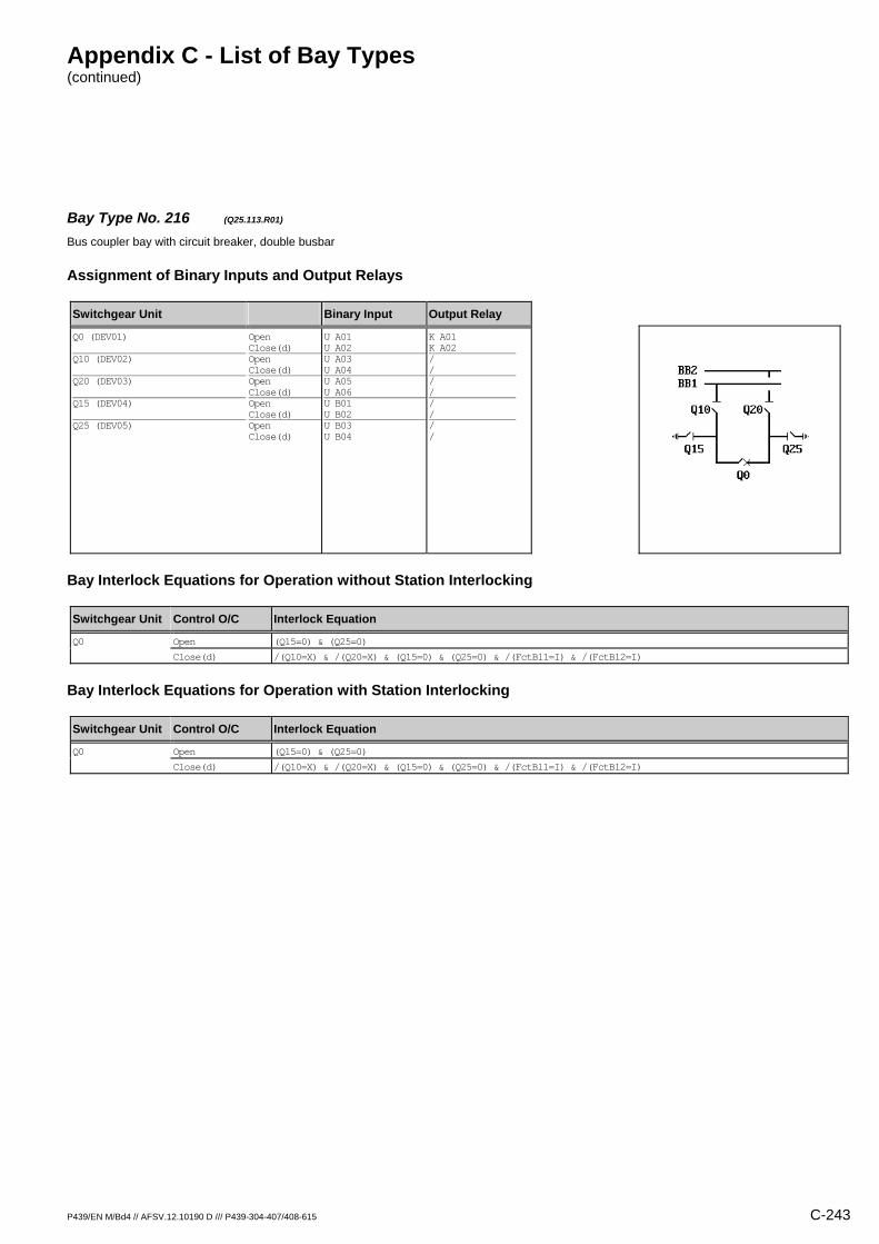
Appendix C - List of Bay Types (continued)
P439/EN M/Bd4 // AFSV.12.10190 D /// P439-304-407/408-615 C-243
Bay Type No. 216 (Q25.113.R01) Bus coupler bay with circuit breaker, double busbar
Assignment of Binary Inputs and Output Relays
Switchgear Unit Binary Input Output Relay
Q0 (DEV01) Q10 (DEV02) Q20 (DEV03) Q15 (DEV04) Q25 (DEV05)
Open Close(d) Open Close(d) Open Close(d) Open Close(d) Open Close(d)
U A01 U A02 U A03 U A04 U A05 U A06 U B01 U B02 U B03 U B04
K A01 K A02 / / / / / / / /
Bay Interlock Equations for Operation without Station Interlocking
Switchgear Unit Control O/C Interlock Equation
Q0 Open (Q15=0) & (Q25=0)
Close(d) /(Q10=X) & /(Q20=X) & (Q15=0) & (Q25=0) & /(FctBl1=I) & /(FctBl2=I)
Bay Interlock Equations for Operation with Station Interlocking
Switchgear Unit Control O/C Interlock Equation
Q0 Open (Q15=0) & (Q25=0)
Close(d) /(Q10=X) & /(Q20=X) & (Q15=0) & (Q25=0) & /(FctBl1=I) & /(FctBl2=I)

Appendix C - List of Bay Types (continued)
C-244 P439/EN M/Bd4 // AFSV.12.10190 D /// P439-304-407/408-615
Bay Type No. 241 (Q25.113.R03) Bus coupler bay with circuit breaker, double busbar
Assignment of Binary Inputs and Output Relays
Switchgear Unit Binary Input Output Relay
Q0 (DEV01) Q10 (DEV02) Q20 (DEV03) Q15 (DEV04) Q25 (DEV05)
Open Close(d) Open Close(d) Open Close(d) Open Close(d) Open Close(d)
U A01 U A02 U A03 U A04 U A05 U A06 U B01 U B02 U B03 U B04
K A01 K A02 K A03 K A04 K A05 K A06 / / / /
Bay Interlock Equations for Operation without Station Interlocking
Switchgear Unit Control O/C Interlock Equation
Q0 Open (Q15=0) & (Q25=0)
Close(d) /(Q10=X) & /(Q20=X) & (Q15=0) & (Q25=0) & /(FctBl1=I) & /(FctBl2=I)
Q10 Open (Q0=0)
Close(d) (Q0=0) & (Q15=0)
Q20 Open (Q0=0)
Close(d) (Q0=0) & (Q25=0)
Bay Interlock Equations for Operation with Station Interlocking
Switchgear Unit Control O/C Interlock Equation
Q0 Open (Q15=0) & (Q25=0)
Close(d) /(Q10=X) & /(Q20=X) & (Q15=0) & (Q25=0) & /(FctBl1=I) & /(FctBl2=I)
Q10 Open (Q0=0)
Close(d) (Q0=0) & (Q15=0)
Q20 Open (Q0=0)
Close(d) (Q0=0) & (Q25=0)
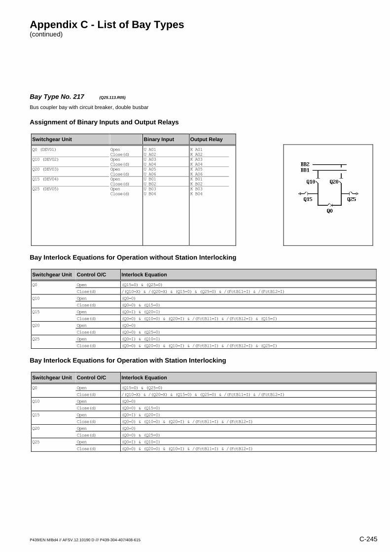
Appendix C - List of Bay Types (continued)
P439/EN M/Bd4 // AFSV.12.10190 D /// P439-304-407/408-615 C-245
Bay Type No. 217 (Q25.113.R05) Bus coupler bay with circuit breaker, double busbar
Assignment of Binary Inputs and Output Relays
Switchgear Unit Binary Input Output Relay
Q0 (DEV01) Q10 (DEV02) Q20 (DEV03) Q15 (DEV04) Q25 (DEV05)
Open Close(d) Open Close(d) Open Close(d) Open Close(d) Open Close(d)
U A01 U A02 U A03 U A04 U A05 U A06 U B01 U B02 U B03 U B04
K A01 K A02 K A03 K A04 K A05 K A06 K B01 K B02 K B03 K B04
Bay Interlock Equations for Operation without Station Interlocking
Switchgear Unit Control O/C Interlock Equation
Q0 Open (Q15=0) & (Q25=0)
Close(d) /(Q10=X) & /(Q20=X) & (Q15=0) & (Q25=0) & /(FctBl1=I) & /(FctBl2=I)
Q10 Open (Q0=0)
Close(d) (Q0=0) & (Q15=0)
Q15 Open (Q0=I) & (Q20=I)
Close(d) (Q0=0) & (Q10=0) & (Q20=I) & /(FctBl1=I) & /(FctBl2=I) & (Q15=I)
Q20 Open (Q0=0)
Close(d) (Q0=0) & (Q25=0)
Q25 Open (Q0=I) & (Q10=I)
Close(d) (Q0=0) & (Q20=0) & (Q10=I) & /(FctBl1=I) & /(FctBl2=I) & (Q25=I)
Bay Interlock Equations for Operation with Station Interlocking
Switchgear Unit Control O/C Interlock Equation
Q0 Open (Q15=0) & (Q25=0)
Close(d) /(Q10=X) & /(Q20=X) & (Q15=0) & (Q25=0) & /(FctBl1=I) & /(FctBl2=I)
Q10 Open (Q0=0)
Close(d) (Q0=0) & (Q15=0)
Q15 Open (Q0=I) & (Q20=I)
Close(d) (Q0=0) & (Q10=0) & (Q20=I) & /(FctBl1=I) & /(FctBl2=I)
Q20 Open (Q0=0)
Close(d) (Q0=0) & (Q25=0)
Q25 Open (Q0=I) & (Q10=I)
Close(d) (Q0=0) & (Q20=0) & (Q10=I) & /(FctBl1=I) & /(FctBl2=I)
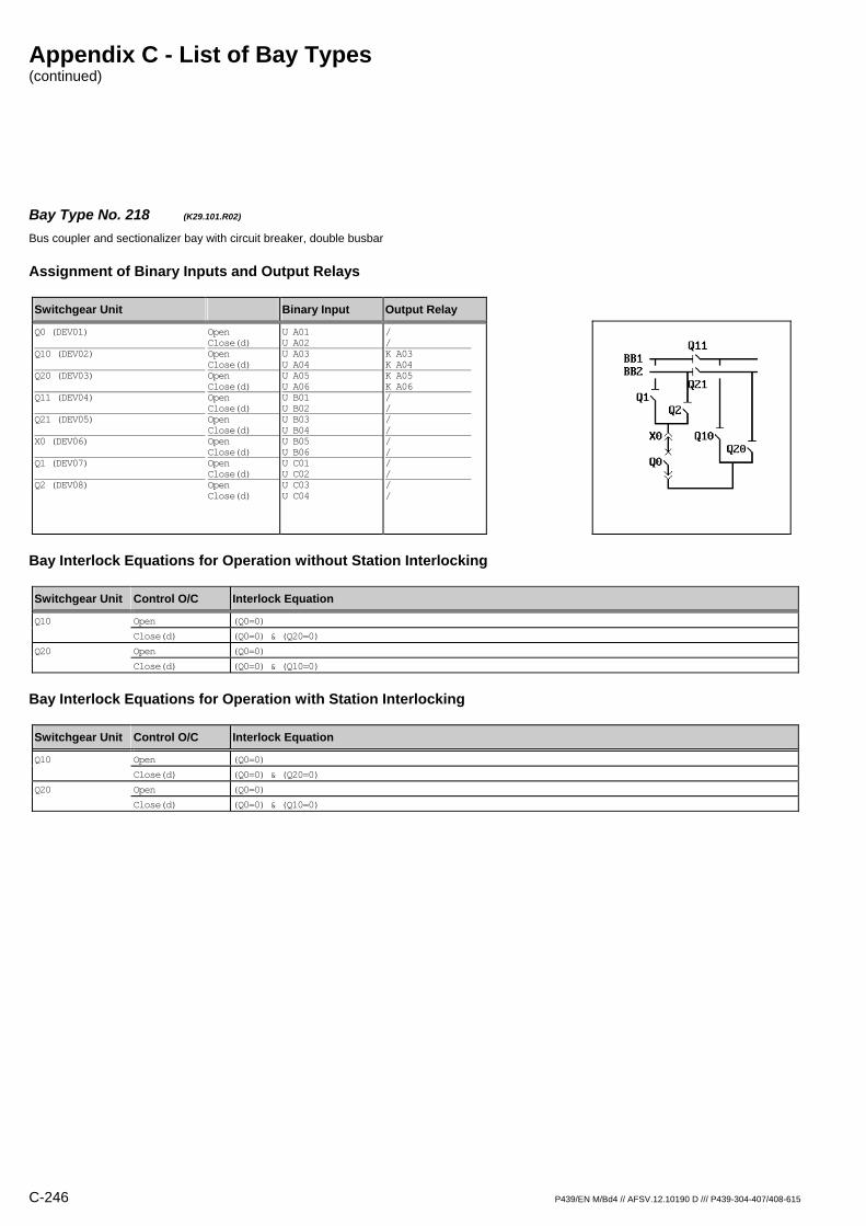
Appendix C - List of Bay Types (continued)
C-246 P439/EN M/Bd4 // AFSV.12.10190 D /// P439-304-407/408-615
Bay Type No. 218 (K29.101.R02) Bus coupler and sectionalizer bay with circuit breaker, double busbar
Assignment of Binary Inputs and Output Relays
Switchgear Unit Binary Input Output Relay
Q0 (DEV01) Q10 (DEV02) Q20 (DEV03) Q11 (DEV04) Q21 (DEV05) X0 (DEV06) Q1 (DEV07) Q2 (DEV08)
Open Close(d) Open Close(d) Open Close(d) Open Close(d) Open Close(d) Open Close(d) Open Close(d) Open Close(d)
U A01 U A02 U A03 U A04 U A05 U A06 U B01 U B02 U B03 U B04 U B05 U B06 U C01 U C02 U C03 U C04
/ / K A03 K A04 K A05 K A06 / / / / / / / / / /
Bay Interlock Equations for Operation without Station Interlocking
Switchgear Unit Control O/C Interlock Equation
Q10 Open (Q0=0)
Close(d) (Q0=0) & (Q20=0)
Q20 Open (Q0=0)
Close(d) (Q0=0) & (Q10=0)
Bay Interlock Equations for Operation with Station Interlocking
Switchgear Unit Control O/C Interlock Equation
Q10 Open (Q0=0)
Close(d) (Q0=0) & (Q20=0)
Q20 Open (Q0=0)
Close(d) (Q0=0) & (Q10=0)
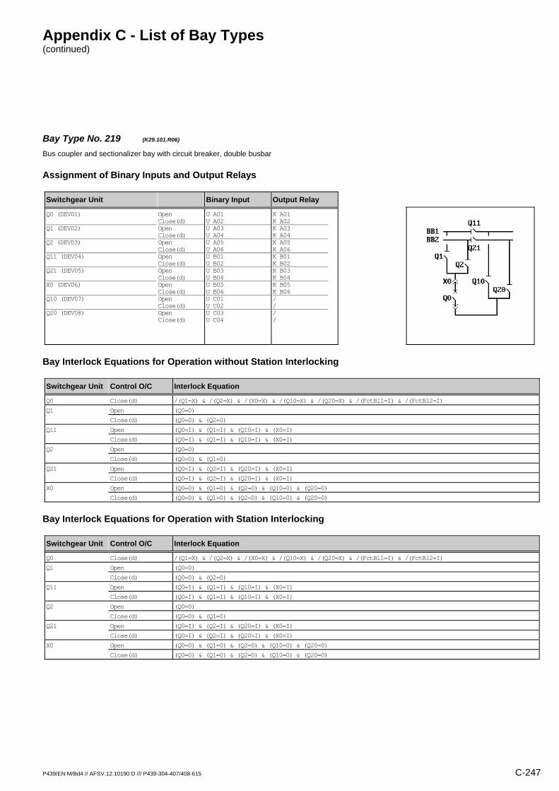
Appendix C - List of Bay Types (continued)
P439/EN M/Bd4 // AFSV.12.10190 D /// P439-304-407/408-615 C-247
Bay Type No. 219 (K29.101.R06) Bus coupler and sectionalizer bay with circuit breaker, double busbar
Assignment of Binary Inputs and Output Relays
Switchgear Unit Binary Input Output Relay
Q0 (DEV01) Q1 (DEV02) Q2 (DEV03) Q11 (DEV04) Q21 (DEV05) X0 (DEV06) Q10 (DEV07) Q20 (DEV08)
Open Close(d) Open Close(d) Open Close(d) Open Close(d) Open Close(d) Open Close(d) Open Close(d) Open Close(d)
U A01 U A02 U A03 U A04 U A05 U A06 U B01 U B02 U B03 U B04 U B05 U B06 U C01 U C02 U C03 U C04
K A01 K A02 K A03 K A04 K A05 K A06 K B01 K B02 K B03 K B04 K B05 K B06 / / / /
Bay Interlock Equations for Operation without Station Interlocking
Switchgear Unit Control O/C Interlock Equation
Q0 Close(d) /(Q1=X) & /(Q2=X) & /(X0=X) & /(Q10=X) & /(Q20=X) & /(FctBl1=I) & /(FctBl2=I)
Q1 Open (Q0=0)
Close(d) (Q0=0) & (Q2=0)
Q11 Open (Q0=I) & (Q1=I) & (Q10=I) & (X0=I)
Close(d) (Q0=I) & (Q1=I) & (Q10=I) & (X0=I)
Q2 Open (Q0=0)
Close(d) (Q0=0) & (Q1=0)
Q21 Open (Q0=I) & (Q2=I) & (Q20=I) & (X0=I)
Close(d) (Q0=I) & (Q2=I) & (Q20=I) & (X0=I)
X0 Open (Q0=0) & (Q1=0) & (Q2=0) & (Q10=0) & (Q20=0)
Close(d) (Q0=0) & (Q1=0) & (Q2=0) & (Q10=0) & (Q20=0)
Bay Interlock Equations for Operation with Station Interlocking
Switchgear Unit Control O/C Interlock Equation
Q0 Close(d) /(Q1=X) & /(Q2=X) & /(X0=X) & /(Q10=X) & /(Q20=X) & /(FctBl1=I) & /(FctBl2=I)
Q1 Open (Q0=0)
Close(d) (Q0=0) & (Q2=0)
Q11 Open (Q0=I) & (Q1=I) & (Q10=I) & (X0=I)
Close(d) (Q0=I) & (Q1=I) & (Q10=I) & (X0=I)
Q2 Open (Q0=0)
Close(d) (Q0=0) & (Q1=0)
Q21 Open (Q0=I) & (Q2=I) & (Q20=I) & (X0=I)
Close(d) (Q0=I) & (Q2=I) & (Q20=I) & (X0=I)
X0 Open (Q0=0) & (Q1=0) & (Q2=0) & (Q10=0) & (Q20=0)
Close(d) (Q0=0) & (Q1=0) & (Q2=0) & (Q10=0) & (Q20=0)

Appendix C - List of Bay Types (continued)
C-248 P439/EN M/Bd4 // AFSV.12.10190 D /// P439-304-407/408-615
Bay Type No. 171 (M11.300.R00) Busbar measurement bay with fuse unit, single busbar
Assignment of Binary Inputs and Output Relays
Switchgear Unit Binary Input Output Relay
X0 (DEV01) F (SIG_1: Signal S011)
Open Close(d)
U A01 U A02 U B05
/ / /
Bay Interlock Equations for Operation without Station Interlocking
Switchgear Unit Control O/C Interlock Equation
Interlock Equations not defined
Bay Interlock Equations for Operation with Station Interlocking
Switchgear Unit Control O/C Interlock Equation
Interlock Equations not defined

Appendix C - List of Bay Types (continued)
P439/EN M/Bd4 // AFSV.12.10190 D /// P439-304-407/408-615 C-249
Bay Type No. 172 (M11.300.R01) Busbar measurement bay with fuse unit, single busbar
Assignment of Binary Inputs and Output Relays
Switchgear Unit Binary Input Output Relay
X0 (DEV01) F (SIG_1: Signal S011)
Open Close(d)
U A01 U A02 U B05
K A01 K A02 /
Bay Interlock Equations for Operation without Station Interlocking
Switchgear Unit Control O/C Interlock Equation
Interlock Equations not defined
Bay Interlock Equations for Operation with Station Interlocking
Switchgear Unit Control O/C Interlock Equation
Interlock Equations not defined
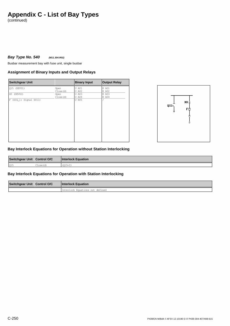
Appendix C - List of Bay Types (continued)
C-250 P439/EN M/Bd4 // AFSV.12.10190 D /// P439-304-407/408-615
Bay Type No. 540 (M11.304.R02) Busbar measurement bay with fuse unit, single busbar
Assignment of Binary Inputs and Output Relays
Switchgear Unit Binary Input Output Relay
Q15 (DEV01) X0 (DEV02) F (SIG_1: Signal S011)
Open Close(d) Open Close(d)
U A01 U A02 U A03 U A04 U B05
K A01 K A02 K A03 K A04 /
Bay Interlock Equations for Operation without Station Interlocking
Switchgear Unit Control O/C Interlock Equation
Q15 Close(d) (Q15=I)
Bay Interlock Equations for Operation with Station Interlocking
Switchgear Unit Control O/C Interlock Equation
Interlock Equations not defined

Appendix C - List of Bay Types (continued)
P439/EN M/Bd4 // AFSV.12.10190 D /// P439-304-407/408-615 C-251
Bay Type No. 173 (M11.900.R00) Busbar measurement bay with other switchgear unit, single busbar
Assignment of Binary Inputs and Output Relays
Switchgear Unit Binary Input Output Relay
X0 (DEV01)
Open Close(d)
U A01 U A02
/ /
Bay Interlock Equations for Operation without Station Interlocking
Switchgear Unit Control O/C Interlock Equation
Interlock Equations not defined
Bay Interlock Equations for Operation with Station Interlocking
Switchgear Unit Control O/C Interlock Equation
Interlock Equations not defined
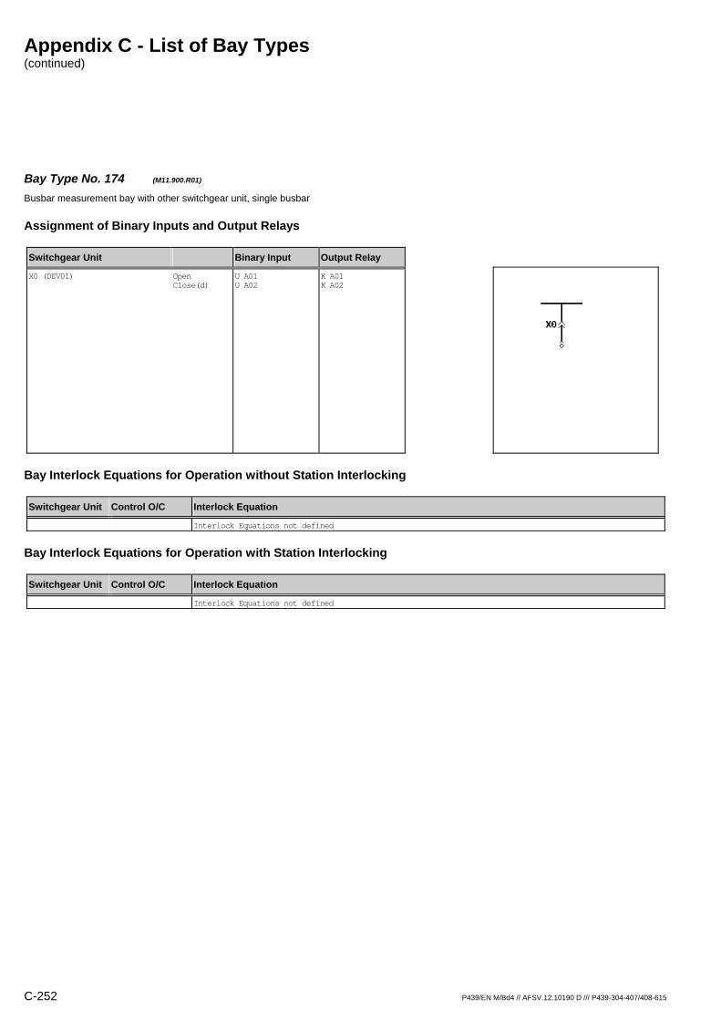
Appendix C - List of Bay Types (continued)
C-252 P439/EN M/Bd4 // AFSV.12.10190 D /// P439-304-407/408-615
Bay Type No. 174 (M11.900.R01) Busbar measurement bay with other switchgear unit, single busbar
Assignment of Binary Inputs and Output Relays
Switchgear Unit Binary Input Output Relay
X0 (DEV01)
Open Close(d)
U A01 U A02
K A01 K A02
Bay Interlock Equations for Operation without Station Interlocking
Switchgear Unit Control O/C Interlock Equation
Interlock Equations not defined
Bay Interlock Equations for Operation with Station Interlocking
Switchgear Unit Control O/C Interlock Equation
Interlock Equations not defined
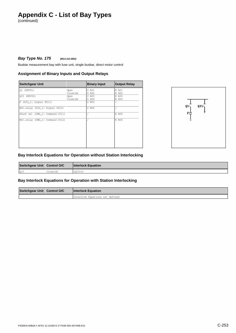
Appendix C - List of Bay Types (continued)
P439/EN M/Bd4 // AFSV.12.10190 D /// P439-304-407/408-615 C-253
Bay Type No. 175 (M13.312.M02) Busbar measurement bay with fuse unit, single busbar, direct motor control
Assignment of Binary Inputs and Output Relays
Switchgear Unit Binary Input Output Relay
Q1 (DEV01) Q15 (DEV02) F (SIG_1: Signal S011) Mot.relay (SIG_1: Signal S012) Shunt wd. (CMD_1: Command C011) Mot.relay (CMD_1: Command C012)
Open Close(d) Open Close(d)
U A01 U A02 U A03 U A04 U B05 U B06 / /
K A01 K A02 K A03 K A04 / / K B05 K B06
Bay Interlock Equations for Operation without Station Interlocking
Switchgear Unit Control O/C Interlock Equation
Q15 Close(d) (Q15=I)
Bay Interlock Equations for Operation with Station Interlocking
Switchgear Unit Control O/C Interlock Equation
Interlock Equations not defined

Appendix C - List of Bay Types (continued)
C-254 P439/EN M/Bd4 // AFSV.12.10190 D /// P439-304-407/408-615
Bay Type No. 176 (M13.312.R01) Busbar measurement bay with fuse unit, single busbar
Assignment of Binary Inputs and Output Relays
Switchgear Unit Binary Input Output Relay
Q1 (DEV01) Q15 (DEV02) F (SIG_1: Signal S011)
Open Close(d) Open Close(d)
U A01 U A02 U A03 U A04 U B05
K A01 K A02 / / /
Bay Interlock Equations for Operation without Station Interlocking
Switchgear Unit Control O/C Interlock Equation
Interlock Equations not defined
Bay Interlock Equations for Operation with Station Interlocking
Switchgear Unit Control O/C Interlock Equation
Interlock Equations not defined

Appendix C - List of Bay Types (continued)
P439/EN M/Bd4 // AFSV.12.10190 D /// P439-304-407/408-615 C-255
Bay Type No. 177 (M13.312.R02) Busbar measurement bay with fuse unit, single busbar
Assignment of Binary Inputs and Output Relays
Switchgear Unit Binary Input Output Relay
Q1 (DEV01) Q15 (DEV02) F (SIG_1: Signal S011)
Open Close(d) Open Close(d)
U A01 U A02 U A03 U A04 U B05
K A01 K A02 K A03 K A04 /
Bay Interlock Equations for Operation without Station Interlocking
Switchgear Unit Control O/C Interlock Equation
Q15 Close(d) (Q15=I)
Bay Interlock Equations for Operation with Station Interlocking
Switchgear Unit Control O/C Interlock Equation
Interlock Equations not defined

Appendix C - List of Bay Types (continued)
C-256 P439/EN M/Bd4 // AFSV.12.10190 D /// P439-304-407/408-615
Bay Type No. 506 (M13.902.R00) Busbar measurement bay with other switchgear unit, single busbar
Assignment of Binary Inputs and Output Relays
Switchgear Unit Binary Input Output Relay
Q1 (DEV01)
Open Close(d)
U A01 U A02
/ /
Bay Interlock Equations for Operation without Station Interlocking
Switchgear Unit Control O/C Interlock Equation
Interlock Equations not defined
Bay Interlock Equations for Operation with Station Interlocking
Switchgear Unit Control O/C Interlock Equation
Interlock Equations not defined
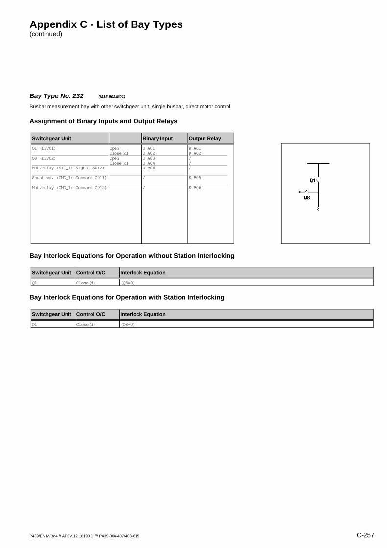
Appendix C - List of Bay Types (continued)
P439/EN M/Bd4 // AFSV.12.10190 D /// P439-304-407/408-615 C-257
Bay Type No. 232 (M15.903.M01) Busbar measurement bay with other switchgear unit, single busbar, direct motor control
Assignment of Binary Inputs and Output Relays
Switchgear Unit Binary Input Output Relay
Q1 (DEV01) Q8 (DEV02) Mot.relay (SIG_1: Signal S012) Shunt wd. (CMD_1: Command C011) Mot.relay (CMD_1: Command C012)
Open Close(d) Open Close(d)
U A01 U A02 U A03 U A04 U B06 / /
K A01 K A02 / / / K B05 K B06
Bay Interlock Equations for Operation without Station Interlocking
Switchgear Unit Control O/C Interlock Equation
Q1 Close(d) (Q8=0)
Bay Interlock Equations for Operation with Station Interlocking
Switchgear Unit Control O/C Interlock Equation
Q1 Close(d) (Q8=0)
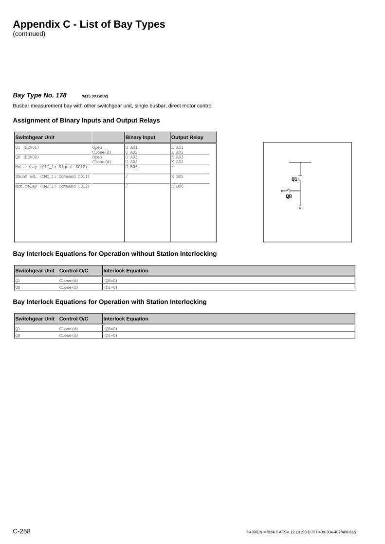
Appendix C - List of Bay Types (continued)
C-258 P439/EN M/Bd4 // AFSV.12.10190 D /// P439-304-407/408-615
Bay Type No. 178 (M15.903.M02) Busbar measurement bay with other switchgear unit, single busbar, direct motor control
Assignment of Binary Inputs and Output Relays
Switchgear Unit Binary Input Output Relay
Q1 (DEV01) Q8 (DEV02) Mot.relay (SIG_1: Signal S012) Shunt wd. (CMD_1: Command C011) Mot.relay (CMD_1: Command C012)
Open Close(d) Open Close(d)
U A01 U A02 U A03 U A04 U B06 / /
K A01 K A02 K A03 K A04 / K B05 K B06
Bay Interlock Equations for Operation without Station Interlocking
Switchgear Unit Control O/C Interlock Equation
Q1 Close(d) (Q8=0)
Q8 Close(d) (Q1=0)
Bay Interlock Equations for Operation with Station Interlocking
Switchgear Unit Control O/C Interlock Equation
Q1 Close(d) (Q8=0)
Q8 Close(d) (Q1=0)

Appendix C - List of Bay Types (continued)
P439/EN M/Bd4 // AFSV.12.10190 D /// P439-304-407/408-615 C-259
Bay Type No. 233 (M15.903.R01) Busbar measurement bay with other switchgear unit, single busbar
Assignment of Binary Inputs and Output Relays
Switchgear Unit Binary Input Output Relay
Q1 (DEV01) Q8 (DEV02)
Open Close(d) Open Close(d)
U A01 U A02 U A03 U A04
K A01 K A02 / /
Bay Interlock Equations for Operation without Station Interlocking
Switchgear Unit Control O/C Interlock Equation
Q1 Close(d) (Q8=0)
Bay Interlock Equations for Operation with Station Interlocking
Switchgear Unit Control O/C Interlock Equation
Q1 Close(d) (Q8=0)
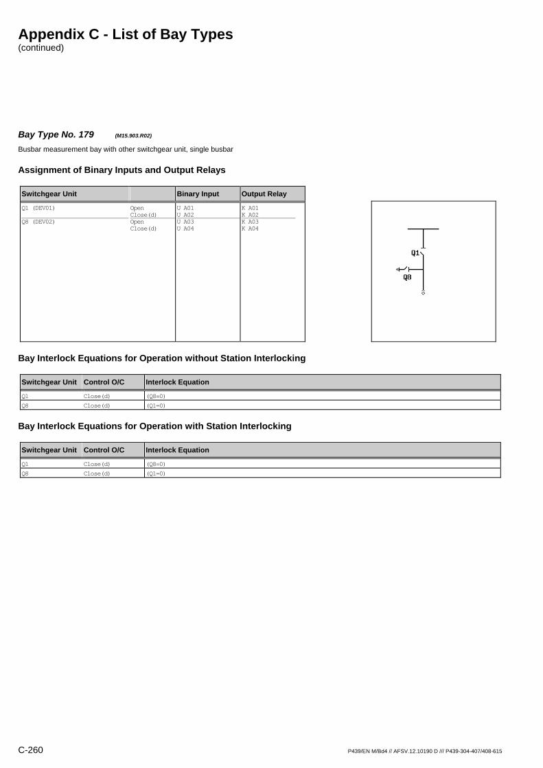
Appendix C - List of Bay Types (continued)
C-260 P439/EN M/Bd4 // AFSV.12.10190 D /// P439-304-407/408-615
Bay Type No. 179 (M15.903.R02) Busbar measurement bay with other switchgear unit, single busbar
Assignment of Binary Inputs and Output Relays
Switchgear Unit Binary Input Output Relay
Q1 (DEV01) Q8 (DEV02)
Open Close(d) Open Close(d)
U A01 U A02 U A03 U A04
K A01 K A02 K A03 K A04
Bay Interlock Equations for Operation without Station Interlocking
Switchgear Unit Control O/C Interlock Equation
Q1 Close(d) (Q8=0)
Q8 Close(d) (Q1=0)
Bay Interlock Equations for Operation with Station Interlocking
Switchgear Unit Control O/C Interlock Equation
Q1 Close(d) (Q8=0)
Q8 Close(d) (Q1=0)
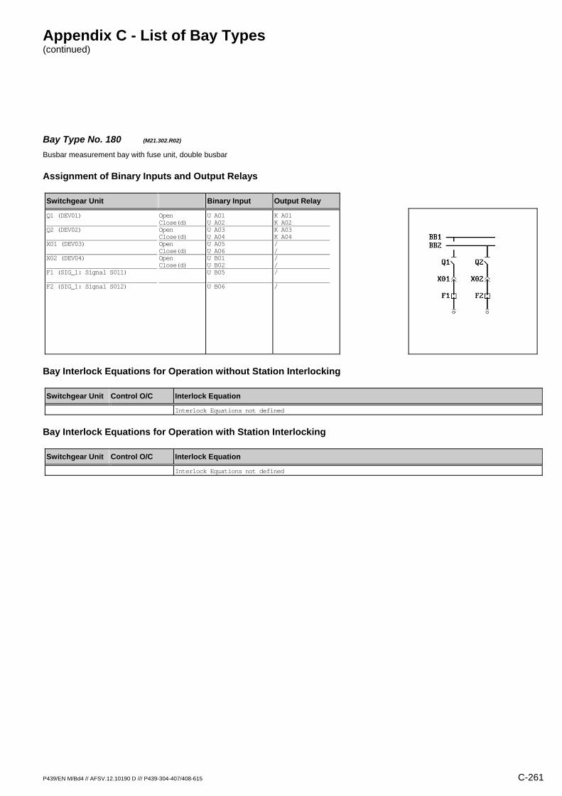
Appendix C - List of Bay Types (continued)
P439/EN M/Bd4 // AFSV.12.10190 D /// P439-304-407/408-615 C-261
Bay Type No. 180 (M21.302.R02) Busbar measurement bay with fuse unit, double busbar
Assignment of Binary Inputs and Output Relays
Switchgear Unit Binary Input Output Relay
Q1 (DEV01) Q2 (DEV02) X01 (DEV03) X02 (DEV04) F1 (SIG_1: Signal S011) F2 (SIG_1: Signal S012)
Open Close(d) Open Close(d) Open Close(d) Open Close(d)
U A01 U A02 U A03 U A04 U A05 U A06 U B01 U B02 U B05 U B06
K A01 K A02 K A03 K A04 / / / / / /
Bay Interlock Equations for Operation without Station Interlocking
Switchgear Unit Control O/C Interlock Equation
Interlock Equations not defined
Bay Interlock Equations for Operation with Station Interlocking
Switchgear Unit Control O/C Interlock Equation
Interlock Equations not defined
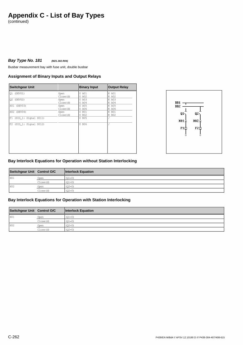
Appendix C - List of Bay Types (continued)
C-262 P439/EN M/Bd4 // AFSV.12.10190 D /// P439-304-407/408-615
Bay Type No. 181 (M21.302.R04) Busbar measurement bay with fuse unit, double busbar
Assignment of Binary Inputs and Output Relays
Switchgear Unit Binary Input Output Relay
Q1 (DEV01) Q2 (DEV02) X01 (DEV03) X02 (DEV04) F1 (SIG_1: Signal S011) F2 (SIG_1: Signal S012)
Open Close(d) Open Close(d) Open Close(d) Open Close(d)
U A01 U A02 U A03 U A04 U A05 U A06 U B01 U B02 U B05 U B06
K A01 K A02 K A03 K A04 K A05 K A06 K B01 K B02 / /
Bay Interlock Equations for Operation without Station Interlocking
Switchgear Unit Control O/C Interlock Equation
X01 Open (Q1=0)
Close(d) (Q1=0)
X02 Open (Q2=0)
Close(d) (Q2=0)
Bay Interlock Equations for Operation with Station Interlocking
Switchgear Unit Control O/C Interlock Equation
X01 Open (Q1=0)
Close(d) (Q1=0)
X02 Open (Q2=0)
Close(d) (Q2=0)
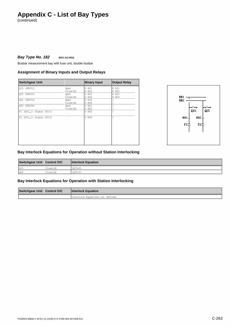
Appendix C - List of Bay Types (continued)
P439/EN M/Bd4 // AFSV.12.10190 D /// P439-304-407/408-615 C-263
Bay Type No. 182 (M21.312.R02) Busbar measurement bay with fuse unit, double busbar
Assignment of Binary Inputs and Output Relays
Switchgear Unit Binary Input Output Relay
Q15 (DEV01) Q25 (DEV02) X01 (DEV03) X02 (DEV04) F1 (SIG_1: Signal S011) F2 (SIG_1: Signal S012)
Open Close(d) Open Close(d) Open Close(d) Open Close(d)
U A01 U A02 U A03 U A04 U A05 U A06 U B01 U B02 U B05 U B06
K A01 K A02 K A03 K A04 / / / / / /
Bay Interlock Equations for Operation without Station Interlocking
Switchgear Unit Control O/C Interlock Equation
Q15 Close(d) (Q15=I)
Q25 Close(d) (Q25=I)
Bay Interlock Equations for Operation with Station Interlocking
Switchgear Unit Control O/C Interlock Equation
Interlock Equations not defined
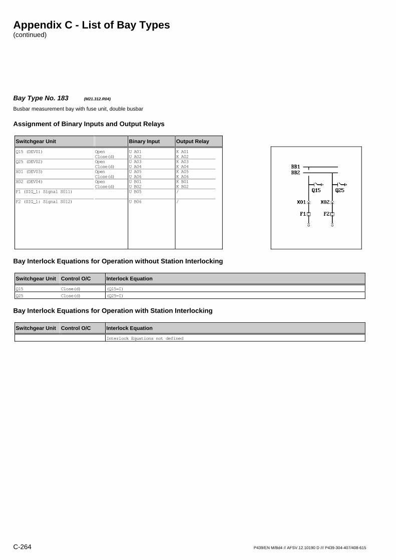
Appendix C - List of Bay Types (continued)
C-264 P439/EN M/Bd4 // AFSV.12.10190 D /// P439-304-407/408-615
Bay Type No. 183 (M21.312.R04) Busbar measurement bay with fuse unit, double busbar
Assignment of Binary Inputs and Output Relays
Switchgear Unit Binary Input Output Relay
Q15 (DEV01) Q25 (DEV02) X01 (DEV03) X02 (DEV04) F1 (SIG_1: Signal S011) F2 (SIG_1: Signal S012)
Open Close(d) Open Close(d) Open Close(d) Open Close(d)
U A01 U A02 U A03 U A04 U A05 U A06 U B01 U B02 U B05 U B06
K A01 K A02 K A03 K A04 K A05 K A06 K B01 K B02 / /
Bay Interlock Equations for Operation without Station Interlocking
Switchgear Unit Control O/C Interlock Equation
Q15 Close(d) (Q15=I)
Q25 Close(d) (Q25=I)
Bay Interlock Equations for Operation with Station Interlocking
Switchgear Unit Control O/C Interlock Equation
Interlock Equations not defined

Appendix C - List of Bay Types (continued)
P439/EN M/Bd4 // AFSV.12.10190 D /// P439-304-407/408-615 C-265
Bay Type No. 184 (M21.902.R02) Busbar measurement bay with other switchgear unit, double busbar
Assignment of Binary Inputs and Output Relays
Switchgear Unit Binary Input Output Relay
Q1 (DEV01) Q2 (DEV02) X01 (DEV03) X02 (DEV04)
Open Close(d) Open Close(d) Open Close(d) Open Close(d)
U A01 U A02 U A03 U A04 U A05 U A06 U B01 U B02
K A01 K A02 K A03 K A04 / / / /
Bay Interlock Equations for Operation without Station Interlocking
Switchgear Unit Control O/C Interlock Equation
Interlock Equations not defined
Bay Interlock Equations for Operation with Station Interlocking
Switchgear Unit Control O/C Interlock Equation
Interlock Equations not defined

Appendix C - List of Bay Types (continued)
C-266 P439/EN M/Bd4 // AFSV.12.10190 D /// P439-304-407/408-615
Bay Type No. 185 (M21.902.R04) Busbar measurement bay with other switchgear unit, double busbar
Assignment of Binary Inputs and Output Relays
Switchgear Unit Binary Input Output Relay
Q1 (DEV01) Q2 (DEV02) X01 (DEV03) X02 (DEV04)
Open Close(d) Open Close(d) Open Close(d) Open Close(d)
U A01 U A02 U A03 U A04 U A05 U A06 U B01 U B02
K A01 K A02 K A03 K A04 K A05 K A06 K B01 K B02
Bay Interlock Equations for Operation without Station Interlocking
Switchgear Unit Control O/C Interlock Equation
X01 Open (Q1=0)
Close(d) (Q1=0)
X02 Open (Q2=0)
Close(d) (Q2=0)
Bay Interlock Equations for Operation with Station Interlocking
Switchgear Unit Control O/C Interlock Equation
X01 Open (Q1=0)
Close(d) (Q1=0)
X02 Open (Q2=0)
Close(d) (Q2=0)

Appendix C - List of Bay Types (continued)
P439/EN M/Bd4 // AFSV.12.10190 D /// P439-304-407/408-615 C-267
Bay Type No. 186 (M21.912.R02) Busbar measurement bay with other switchgear unit, double busbar
Assignment of Binary Inputs and Output Relays
Switchgear Unit Binary Input Output Relay
Q15 (DEV01) Q25 (DEV02) X01 (DEV03) X02 (DEV04)
Open Close(d) Open Close(d) Open Close(d) Open Close(d)
U A01 U A02 U A03 U A04 U A05 U A06 U B01 U B02
K A01 K A02 K A03 K A04 / / / /
Bay Interlock Equations for Operation without Station Interlocking
Switchgear Unit Control O/C Interlock Equation
Q15 Close(d) (Q15=I)
Q25 Close(d) (Q25=I)
Bay Interlock Equations for Operation with Station Interlocking
Switchgear Unit Control O/C Interlock Equation
Interlock Equations not defined

Appendix C - List of Bay Types (continued)
C-268 P439/EN M/Bd4 // AFSV.12.10190 D /// P439-304-407/408-615
Bay Type No. 187 (M21.912.R04) Busbar measurement bay with other switchgear unit, double busbar
Assignment of Binary Inputs and Output Relays
Switchgear Unit Binary Input Output Relay
Q15 (DEV01) Q25 (DEV02) X01 (DEV03) X02 (DEV04)
Open Close(d) Open Close(d) Open Close(d) Open Close(d)
U A01 U A02 U A03 U A04 U A05 U A06 U B01 U B02
K A01 K A02 K A03 K A04 K A05 K A06 K B01 K B02
Bay Interlock Equations for Operation without Station Interlocking
Switchgear Unit Control O/C Interlock Equation
Q15 Close(d) (Q15=I)
Q25 Close(d) (Q25=I)
Bay Interlock Equations for Operation with Station Interlocking
Switchgear Unit Control O/C Interlock Equation
Interlock Equations not defined

Appendix C - List of Bay Types (continued)
P439/EN M/Bd4 // AFSV.12.10190 D /// P439-304-407/408-615 C-269
Bay Type No. 188 (M23.302.R02) Busbar measurement bay with fuse unit, double busbar
Assignment of Binary Inputs and Output Relays
Switchgear Unit Binary Input Output Relay
Q1 (DEV01) Q2 (DEV02) F1 (SIG_1: Signal S011) F2 (SIG_1: Signal S012)
Open Close(d) Open Close(d)
U A01 U A02 U A03 U A04 U B05 U B06
K A01 K A02 K A03 K A04 / /
Bay Interlock Equations for Operation without Station Interlocking
Switchgear Unit Control O/C Interlock Equation
Interlock Equations not defined
Bay Interlock Equations for Operation with Station Interlocking
Switchgear Unit Control O/C Interlock Equation
Interlock Equations not defined
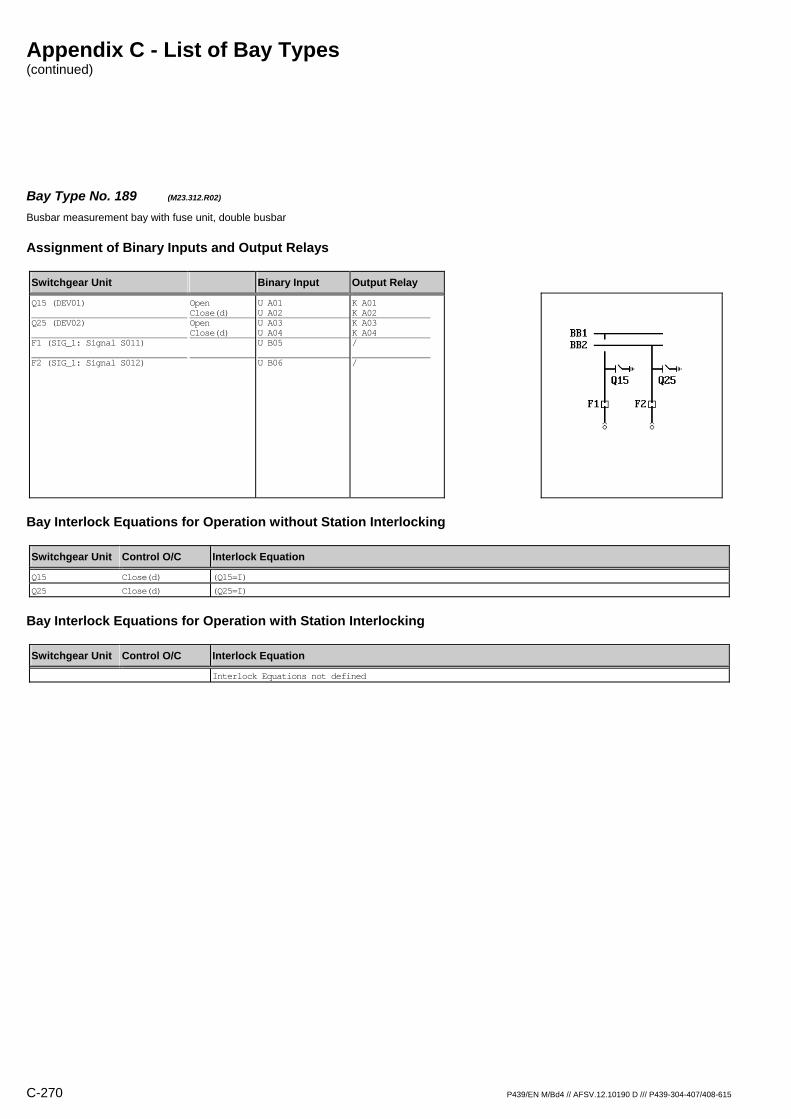
Appendix C - List of Bay Types (continued)
C-270 P439/EN M/Bd4 // AFSV.12.10190 D /// P439-304-407/408-615
Bay Type No. 189 (M23.312.R02) Busbar measurement bay with fuse unit, double busbar
Assignment of Binary Inputs and Output Relays
Switchgear Unit Binary Input Output Relay
Q15 (DEV01) Q25 (DEV02) F1 (SIG_1: Signal S011) F2 (SIG_1: Signal S012)
Open Close(d) Open Close(d)
U A01 U A02 U A03 U A04 U B05 U B06
K A01 K A02 K A03 K A04 / /
Bay Interlock Equations for Operation without Station Interlocking
Switchgear Unit Control O/C Interlock Equation
Q15 Close(d) (Q15=I)
Q25 Close(d) (Q25=I)
Bay Interlock Equations for Operation with Station Interlocking
Switchgear Unit Control O/C Interlock Equation
Interlock Equations not defined

Appendix C - List of Bay Types (continued)
P439/EN M/Bd4 // AFSV.12.10190 D /// P439-304-407/408-615 C-271
Bay Type No. 190 (M23.328.M04) Busbar measurement bay with fuse unit, double busbar, direct motor control
Assignment of Binary Inputs and Output Relays
Switchgear Unit Binary Input Output Relay
Q1 (DEV01) Q2 (DEV02) Q15 (DEV03) Q25 (DEV04) F2 (SIG_1: Signal S010) F1 (SIG_1: Signal S011) Mot.relay (SIG_1: Signal S012) Shunt wd. (CMD_1: Command C011) Mot.relay (CMD_1: Command C012)
Open Close(d) Open Close(d) Open Close(d) Open Close(d)
U A01 U A02 U A03 U A04 U A05 U A06 U B01 U B02 U B04 U B05 U B06 / /
K A01 K A02 K A03 K A04 K A05 K A06 K B01 K B02 / / / K B05 K B06
Bay Interlock Equations for Operation without Station Interlocking
Switchgear Unit Control O/C Interlock Equation
Q15 Close(d) (Q15=I)
Q25 Close(d) (Q25=I)
Bay Interlock Equations for Operation with Station Interlocking
Switchgear Unit Control O/C Interlock Equation
Interlock Equations not defined

Appendix C - List of Bay Types (continued)
C-272 P439/EN M/Bd4 // AFSV.12.10190 D /// P439-304-407/408-615
Bay Type No. 191 (M23.328.R02) Busbar measurement bay with fuse unit, double busbar
Assignment of Binary Inputs and Output Relays
Switchgear Unit Binary Input Output Relay
Q1 (DEV01) Q2 (DEV02) Q15 (DEV03) Q25 (DEV04) F1 (SIG_1: Signal S011) F2 (SIG_1: Signal S012)
Open Close(d) Open Close(d) Open Close(d) Open Close(d)
U A01 U A02 U A03 U A04 U A05 U A06 U B01 U B02 U B05 U B06
K A01 K A02 K A03 K A04 / / / / / /
Bay Interlock Equations for Operation without Station Interlocking
Switchgear Unit Control O/C Interlock Equation
Interlock Equations not defined
Bay Interlock Equations for Operation with Station Interlocking
Switchgear Unit Control O/C Interlock Equation
Interlock Equations not defined

Appendix C - List of Bay Types (continued)
P439/EN M/Bd4 // AFSV.12.10190 D /// P439-304-407/408-615 C-273
Bay Type No. 192 (M23.328.R04) Busbar measurement bay with fuse unit, double busbar
Assignment of Binary Inputs and Output Relays
Switchgear Unit Binary Input Output Relay
Q1 (DEV01) Q2 (DEV02) Q15 (DEV03) Q25 (DEV04) F1 (SIG_1: Signal S011) F2 (SIG_1: Signal S012)
Open Close(d) Open Close(d) Open Close(d) Open Close(d)
U A01 U A02 U A03 U A04 U A05 U A06 U B01 U B02 U B05 U B06
K A01 K A02 K A03 K A04 K A05 K A06 K B01 K B02 / /
Bay Interlock Equations for Operation without Station Interlocking
Switchgear Unit Control O/C Interlock Equation
Q15 Close(d) (Q15=I)
Q25 Close(d) (Q25=I)
Bay Interlock Equations for Operation with Station Interlocking
Switchgear Unit Control O/C Interlock Equation
Interlock Equations not defined

Appendix C - List of Bay Types (continued)
C-274 P439/EN M/Bd4 // AFSV.12.10190 D /// P439-304-407/408-615
Bay Type No. 193 (M23.902.R02) Busbar measurement bay with other switchgear unit, double busbar
Assignment of Binary Inputs and Output Relays
Switchgear Unit Binary Input Output Relay
Q1 (DEV01) Q2 (DEV02)
Open Close(d) Open Close(d)
U A01 U A02 U A03 U A04
K A01 K A02 K A03 K A04
Bay Interlock Equations for Operation without Station Interlocking
Switchgear Unit Control O/C Interlock Equation
Interlock Equations not defined
Bay Interlock Equations for Operation with Station Interlocking
Switchgear Unit Control O/C Interlock Equation
Interlock Equations not defined

Appendix C - List of Bay Types (continued)
P439/EN M/Bd4 // AFSV.12.10190 D /// P439-304-407/408-615 C-275
Bay Type No. 559 (M23.904.R00) Busbar measurement bay with other switchgear unit, double busbar
Assignment of Binary Inputs and Output Relays
Switchgear Unit Binary Input Output Relay
Q15 (DEV01)
Open Close(d)
U A01 U A02
/ /
Bay Interlock Equations for Operation without Station Interlocking
Switchgear Unit Control O/C Interlock Equation
Interlock Equations not defined
Bay Interlock Equations for Operation with Station Interlocking
Switchgear Unit Control O/C Interlock Equation
Interlock Equations not defined
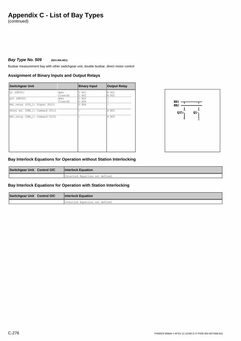
Appendix C - List of Bay Types (continued)
C-276 P439/EN M/Bd4 // AFSV.12.10190 D /// P439-304-407/408-615
Bay Type No. 509 (M23.906.M01) Busbar measurement bay with other switchgear unit, double busbar, direct motor control
Assignment of Binary Inputs and Output Relays
Switchgear Unit Binary Input Output Relay
Q1 (DEV01) Q15 (DEV02) Mot.relay (SIG_1: Signal S012) Shunt wd. (CMD_1: Command C011) Mot.relay (CMD_1: Command C012)
Open Close(d) Open Close(d)
U A01 U A02 U A03 U A04 U B06 / /
K A01 K A02 / / / K B05 K B06
Bay Interlock Equations for Operation without Station Interlocking
Switchgear Unit Control O/C Interlock Equation
Interlock Equations not defined
Bay Interlock Equations for Operation with Station Interlocking
Switchgear Unit Control O/C Interlock Equation
Interlock Equations not defined
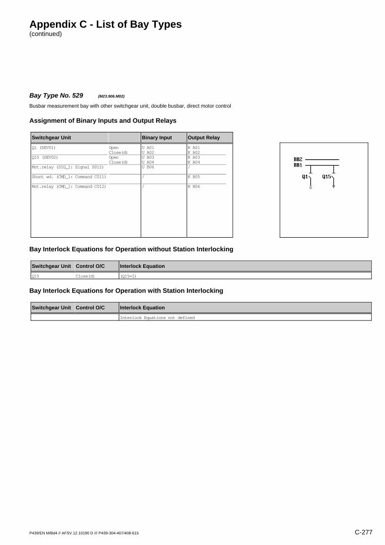
Appendix C - List of Bay Types (continued)
P439/EN M/Bd4 // AFSV.12.10190 D /// P439-304-407/408-615 C-277
Bay Type No. 529 (M23.906.M02) Busbar measurement bay with other switchgear unit, double busbar, direct motor control
Assignment of Binary Inputs and Output Relays
Switchgear Unit Binary Input Output Relay
Q1 (DEV01) Q15 (DEV02) Mot.relay (SIG_1: Signal S012) Shunt wd. (CMD_1: Command C011) Mot.relay (CMD_1: Command C012)
Open Close(d) Open Close(d)
U A01 U A02 U A03 U A04 U B06 / /
K A01 K A02 K A03 K A04 / K B05 K B06
Bay Interlock Equations for Operation without Station Interlocking
Switchgear Unit Control O/C Interlock Equation
Q15 Close(d) (Q15=I)
Bay Interlock Equations for Operation with Station Interlocking
Switchgear Unit Control O/C Interlock Equation
Interlock Equations not defined
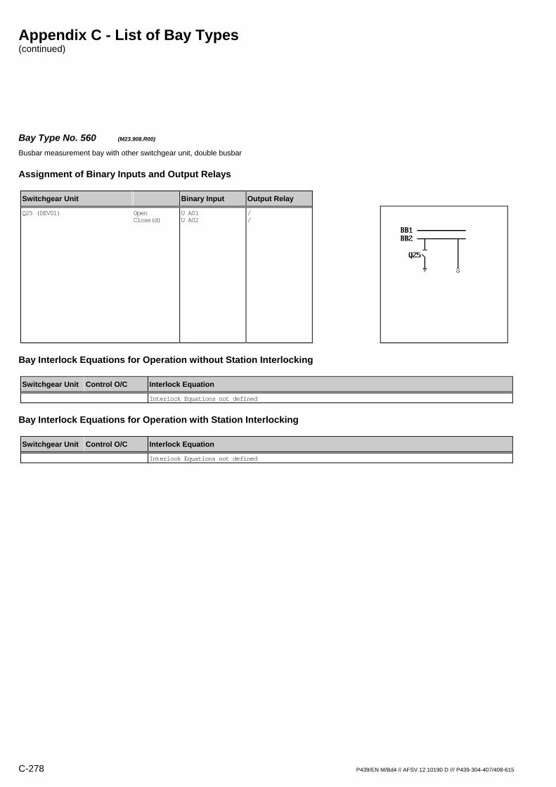
Appendix C - List of Bay Types (continued)
C-278 P439/EN M/Bd4 // AFSV.12.10190 D /// P439-304-407/408-615
Bay Type No. 560 (M23.908.R00) Busbar measurement bay with other switchgear unit, double busbar
Assignment of Binary Inputs and Output Relays
Switchgear Unit Binary Input Output Relay
Q25 (DEV01)
Open Close(d)
U A01 U A02
/ /
Bay Interlock Equations for Operation without Station Interlocking
Switchgear Unit Control O/C Interlock Equation
Interlock Equations not defined
Bay Interlock Equations for Operation with Station Interlocking
Switchgear Unit Control O/C Interlock Equation
Interlock Equations not defined

Appendix C - List of Bay Types (continued)
P439/EN M/Bd4 // AFSV.12.10190 D /// P439-304-407/408-615 C-279
Bay Type No. 510 (M23.910.M01) Busbar measurement bay with other switchgear unit, double busbar, direct motor control
Assignment of Binary Inputs and Output Relays
Switchgear Unit Binary Input Output Relay
Q2 (DEV01) Q25 (DEV02) Mot.relay (SIG_1: Signal S012) Shunt wd. (CMD_1: Command C011) Mot.relay (CMD_1: Command C012)
Open Close(d) Open Close(d)
U A01 U A02 U A03 U A04 U B06 / /
K A01 K A02 / / / K B05 K B06
Bay Interlock Equations for Operation without Station Interlocking
Switchgear Unit Control O/C Interlock Equation
Interlock Equations not defined
Bay Interlock Equations for Operation with Station Interlocking
Switchgear Unit Control O/C Interlock Equation
Interlock Equations not defined
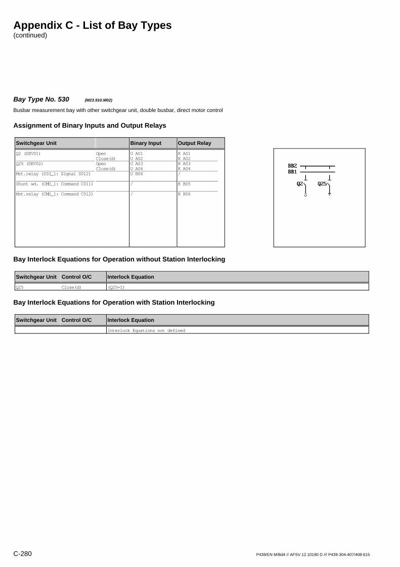
Appendix C - List of Bay Types (continued)
C-280 P439/EN M/Bd4 // AFSV.12.10190 D /// P439-304-407/408-615
Bay Type No. 530 (M23.910.M02) Busbar measurement bay with other switchgear unit, double busbar, direct motor control
Assignment of Binary Inputs and Output Relays
Switchgear Unit Binary Input Output Relay
Q2 (DEV01) Q25 (DEV02) Mot.relay (SIG_1: Signal S012) Shunt wd. (CMD_1: Command C011) Mot.relay (CMD_1: Command C012)
Open Close(d) Open Close(d)
U A01 U A02 U A03 U A04 U B06 / /
K A01 K A02 K A03 K A04 / K B05 K B06
Bay Interlock Equations for Operation without Station Interlocking
Switchgear Unit Control O/C Interlock Equation
Q25 Close(d) (Q25=I)
Bay Interlock Equations for Operation with Station Interlocking
Switchgear Unit Control O/C Interlock Equation
Interlock Equations not defined

Appendix C - List of Bay Types (continued)
P439/EN M/Bd4 // AFSV.12.10190 D /// P439-304-407/408-615 C-281
Bay Type No. 194 (M23.912.R02) Busbar measurement bay with other switchgear unit, double busbar
Assignment of Binary Inputs and Output Relays
Switchgear Unit Binary Input Output Relay
Q15 (DEV01) Q25 (DEV02)
Open Close(d) Open Close(d)
U A01 U A02 U A03 U A04
K A01 K A02 K A03 K A04
Bay Interlock Equations for Operation without Station Interlocking
Switchgear Unit Control O/C Interlock Equation
Q15 Close(d) (Q15=I)
Q25 Close(d) (Q25=I)
Bay Interlock Equations for Operation with Station Interlocking
Switchgear Unit Control O/C Interlock Equation
Interlock Equations not defined
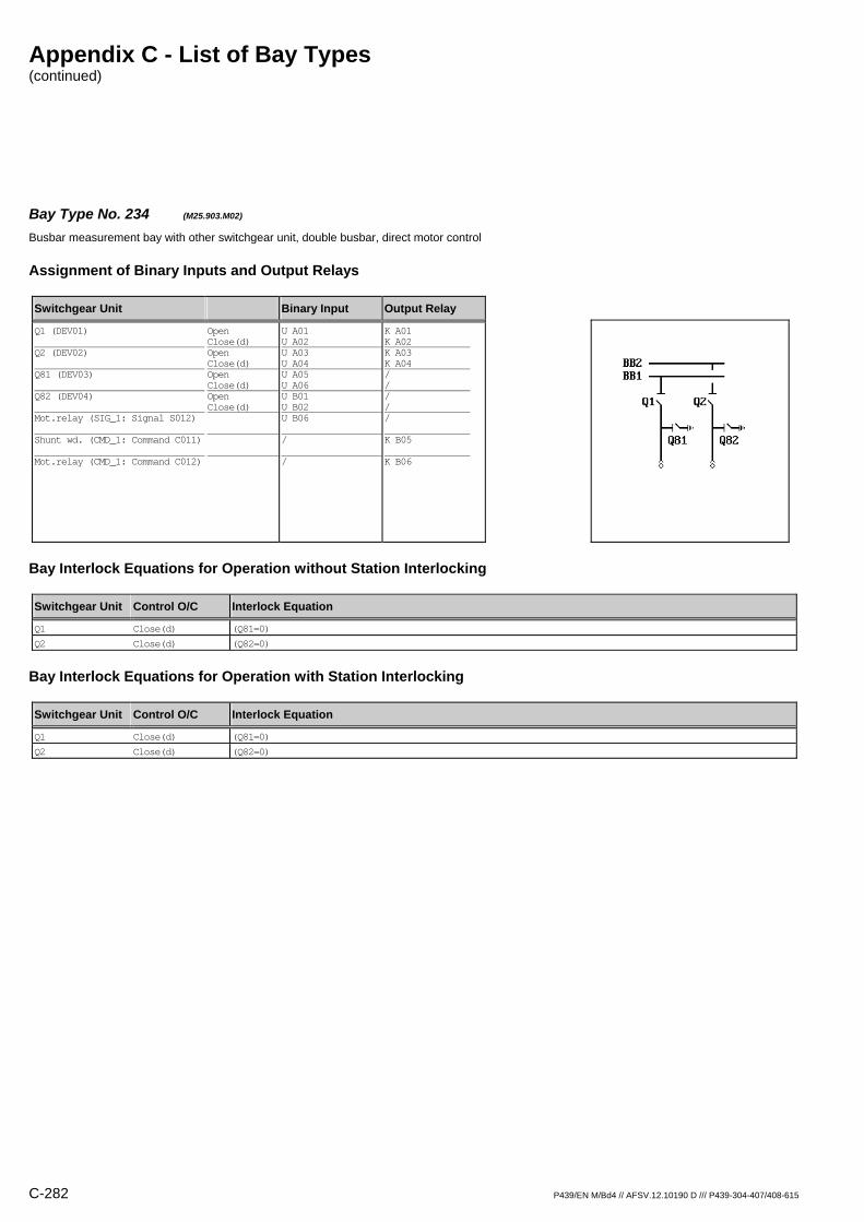
Appendix C - List of Bay Types (continued)
C-282 P439/EN M/Bd4 // AFSV.12.10190 D /// P439-304-407/408-615
Bay Type No. 234 (M25.903.M02) Busbar measurement bay with other switchgear unit, double busbar, direct motor control
Assignment of Binary Inputs and Output Relays
Switchgear Unit Binary Input Output Relay
Q1 (DEV01) Q2 (DEV02) Q81 (DEV03) Q82 (DEV04) Mot.relay (SIG_1: Signal S012) Shunt wd. (CMD_1: Command C011) Mot.relay (CMD_1: Command C012)
Open Close(d) Open Close(d) Open Close(d) Open Close(d)
U A01 U A02 U A03 U A04 U A05 U A06 U B01 U B02 U B06 / /
K A01 K A02 K A03 K A04 / / / / / K B05 K B06
Bay Interlock Equations for Operation without Station Interlocking
Switchgear Unit Control O/C Interlock Equation
Q1 Close(d) (Q81=0)
Q2 Close(d) (Q82=0)
Bay Interlock Equations for Operation with Station Interlocking
Switchgear Unit Control O/C Interlock Equation
Q1 Close(d) (Q81=0)
Q2 Close(d) (Q82=0)
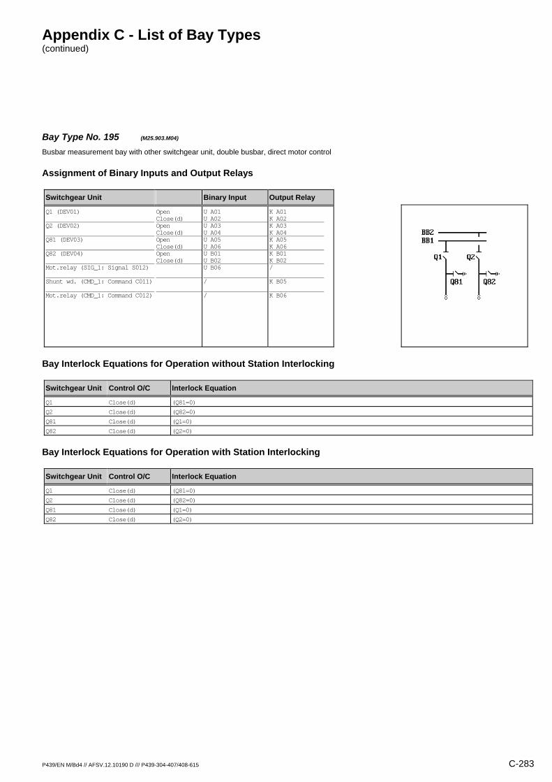
Appendix C - List of Bay Types (continued)
P439/EN M/Bd4 // AFSV.12.10190 D /// P439-304-407/408-615 C-283
Bay Type No. 195 (M25.903.M04) Busbar measurement bay with other switchgear unit, double busbar, direct motor control
Assignment of Binary Inputs and Output Relays
Switchgear Unit Binary Input Output Relay
Q1 (DEV01) Q2 (DEV02) Q81 (DEV03) Q82 (DEV04) Mot.relay (SIG_1: Signal S012) Shunt wd. (CMD_1: Command C011) Mot.relay (CMD_1: Command C012)
Open Close(d) Open Close(d) Open Close(d) Open Close(d)
U A01 U A02 U A03 U A04 U A05 U A06 U B01 U B02 U B06 / /
K A01 K A02 K A03 K A04 K A05 K A06 K B01 K B02 / K B05 K B06
Bay Interlock Equations for Operation without Station Interlocking
Switchgear Unit Control O/C Interlock Equation
Q1 Close(d) (Q81=0)
Q2 Close(d) (Q82=0)
Q81 Close(d) (Q1=0)
Q82 Close(d) (Q2=0)
Bay Interlock Equations for Operation with Station Interlocking
Switchgear Unit Control O/C Interlock Equation
Q1 Close(d) (Q81=0)
Q2 Close(d) (Q82=0)
Q81 Close(d) (Q1=0)
Q82 Close(d) (Q2=0)
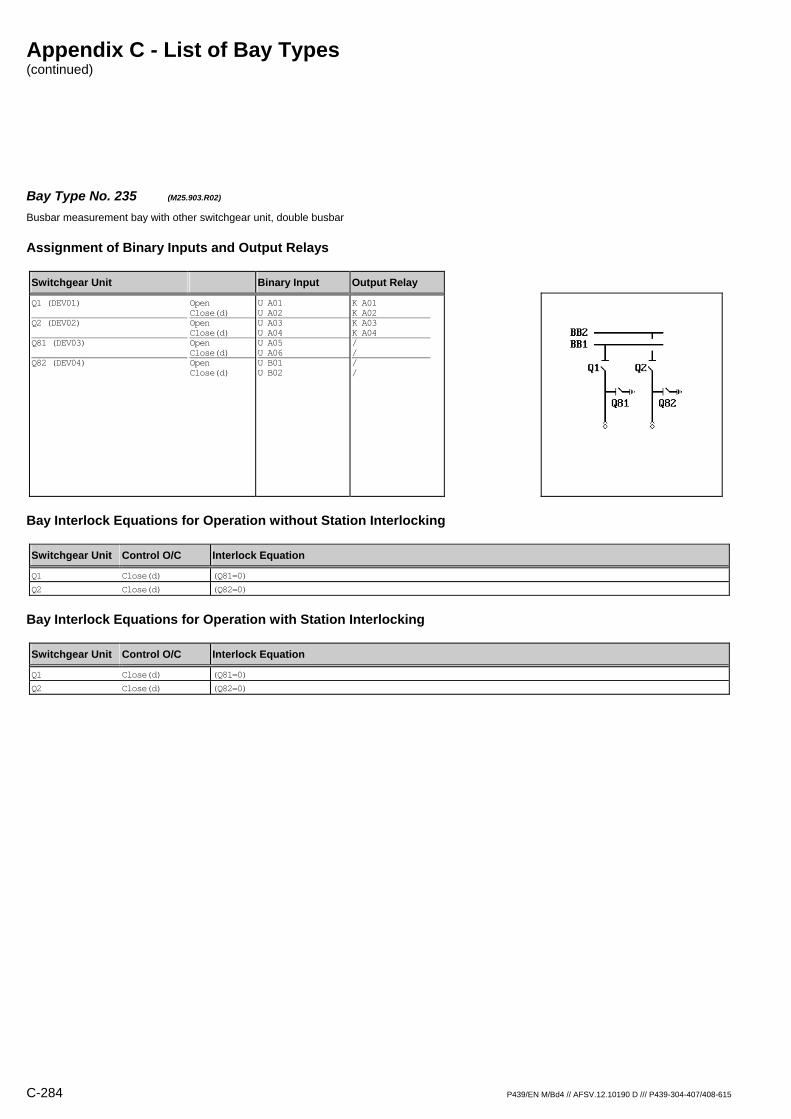
Appendix C - List of Bay Types (continued)
C-284 P439/EN M/Bd4 // AFSV.12.10190 D /// P439-304-407/408-615
Bay Type No. 235 (M25.903.R02) Busbar measurement bay with other switchgear unit, double busbar
Assignment of Binary Inputs and Output Relays
Switchgear Unit Binary Input Output Relay
Q1 (DEV01) Q2 (DEV02) Q81 (DEV03) Q82 (DEV04)
Open Close(d) Open Close(d) Open Close(d) Open Close(d)
U A01 U A02 U A03 U A04 U A05 U A06 U B01 U B02
K A01 K A02 K A03 K A04 / / / /
Bay Interlock Equations for Operation without Station Interlocking
Switchgear Unit Control O/C Interlock Equation
Q1 Close(d) (Q81=0)
Q2 Close(d) (Q82=0)
Bay Interlock Equations for Operation with Station Interlocking
Switchgear Unit Control O/C Interlock Equation
Q1 Close(d) (Q81=0)
Q2 Close(d) (Q82=0)

Appendix C - List of Bay Types (continued)
P439/EN M/Bd4 // AFSV.12.10190 D /// P439-304-407/408-615 C-285
Bay Type No. 196 (M25.903.R04) Busbar measurement bay with other switchgear unit, double busbar
Assignment of Binary Inputs and Output Relays
Switchgear Unit Binary Input Output Relay
Q1 (DEV01) Q2 (DEV02) Q81 (DEV03) Q82 (DEV04)
Open Close(d) Open Close(d) Open Close(d) Open Close(d)
U A01 U A02 U A03 U A04 U A05 U A06 U B01 U B02
K A01 K A02 K A03 K A04 K A05 K A06 K B01 K B02
Bay Interlock Equations for Operation without Station Interlocking
Switchgear Unit Control O/C Interlock Equation
Q1 Close(d) (Q81=0)
Q2 Close(d) (Q82=0)
Q81 Close(d) (Q1=0)
Q82 Close(d) (Q2=0)
Bay Interlock Equations for Operation with Station Interlocking
Switchgear Unit Control O/C Interlock Equation
Q1 Close(d) (Q81=0)
Q2 Close(d) (Q82=0)
Q81 Close(d) (Q1=0)
Q82 Close(d) (Q2=0)
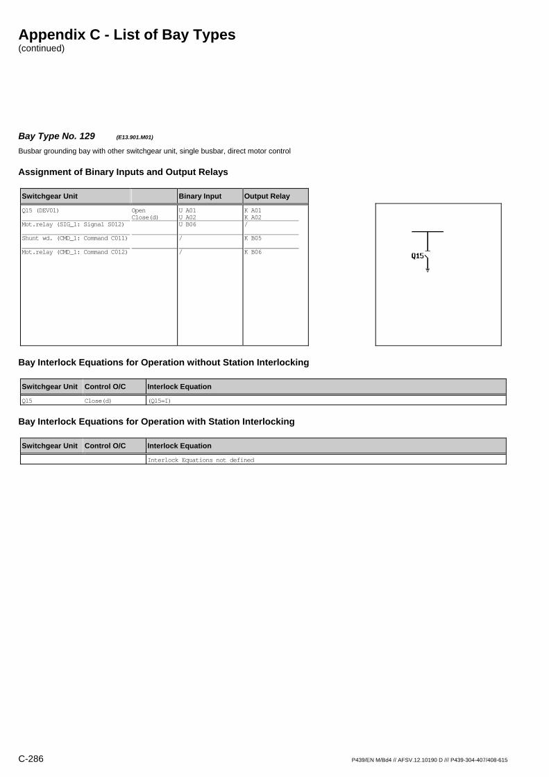
Appendix C - List of Bay Types (continued)
C-286 P439/EN M/Bd4 // AFSV.12.10190 D /// P439-304-407/408-615
Bay Type No. 129 (E13.901.M01) Busbar grounding bay with other switchgear unit, single busbar, direct motor control
Assignment of Binary Inputs and Output Relays
Switchgear Unit Binary Input Output Relay
Q15 (DEV01) Mot.relay (SIG_1: Signal S012) Shunt wd. (CMD_1: Command C011) Mot.relay (CMD_1: Command C012)
Open Close(d)
U A01 U A02 U B06 / /
K A01 K A02 / K B05 K B06
Bay Interlock Equations for Operation without Station Interlocking
Switchgear Unit Control O/C Interlock Equation
Q15 Close(d) (Q15=I)
Bay Interlock Equations for Operation with Station Interlocking
Switchgear Unit Control O/C Interlock Equation
Interlock Equations not defined

Appendix C - List of Bay Types (continued)
P439/EN M/Bd4 // AFSV.12.10190 D /// P439-304-407/408-615 C-287
Bay Type No. 130 (E13.901.R01) Busbar grounding bay with other switchgear unit, single busbar
Assignment of Binary Inputs and Output Relays
Switchgear Unit Binary Input Output Relay
Q15 (DEV01)
Open Close(d)
U A01 U A02
K A01 K A02
Bay Interlock Equations for Operation without Station Interlocking
Switchgear Unit Control O/C Interlock Equation
Q15 Close(d) (Q15=I)
Bay Interlock Equations for Operation with Station Interlocking
Switchgear Unit Control O/C Interlock Equation
Interlock Equations not defined
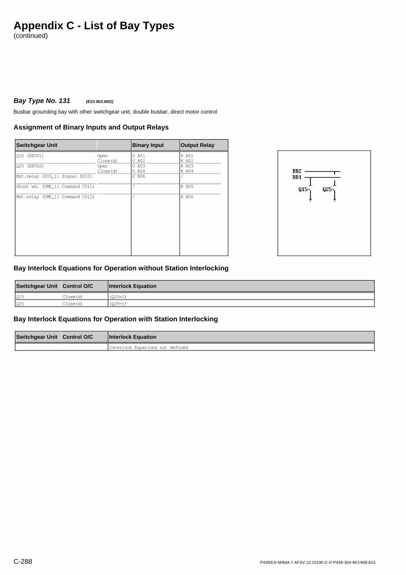
Appendix C - List of Bay Types (continued)
C-288 P439/EN M/Bd4 // AFSV.12.10190 D /// P439-304-407/408-615
Bay Type No. 131 (E23.903.M02) Busbar grounding bay with other switchgear unit, double busbar, direct motor control
Assignment of Binary Inputs and Output Relays
Switchgear Unit Binary Input Output Relay
Q15 (DEV01) Q25 (DEV02) Mot.relay (SIG_1: Signal S012) Shunt wd. (CMD_1: Command C011) Mot.relay (CMD_1: Command C012)
Open Close(d) Open Close(d)
U A01 U A02 U A03 U A04 U B06 / /
K A01 K A02 K A03 K A04 / K B05 K B06
Bay Interlock Equations for Operation without Station Interlocking
Switchgear Unit Control O/C Interlock Equation
Q15 Close(d) (Q15=I)
Q25 Close(d) (Q25=I)
Bay Interlock Equations for Operation with Station Interlocking
Switchgear Unit Control O/C Interlock Equation
Interlock Equations not defined
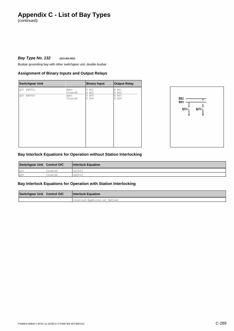
Appendix C - List of Bay Types (continued)
P439/EN M/Bd4 // AFSV.12.10190 D /// P439-304-407/408-615 C-289
Bay Type No. 132 (E23.903.R02) Busbar grounding bay with other switchgear unit, double busbar
Assignment of Binary Inputs and Output Relays
Switchgear Unit Binary Input Output Relay
Q15 (DEV01) Q25 (DEV02)
Open Close(d) Open Close(d)
U A01 U A02 U A03 U A04
K A01 K A02 K A03 K A04
Bay Interlock Equations for Operation without Station Interlocking
Switchgear Unit Control O/C Interlock Equation
Q15 Close(d) (Q15=I)
Q25 Close(d) (Q25=I)
Bay Interlock Equations for Operation with Station Interlocking
Switchgear Unit Control O/C Interlock Equation
Interlock Equations not defined
Appendix C - List of Bay Types (continued)
C-290 P439/EN M/Bd4 // AFSV.12.10190 D /// P439-304-407/408-615
Bay Type No. 1 (X99.901.R00) Other bay type with other switchgear unit, without busbar
Assignment of Binary Inputs and Output Relays
Switchgear Unit Binary Input Output Relay
Bay Interlock Equations for Operation without Station Interlocking
Switchgear Unit Control O/C Interlock Equation
Interlock Equations not defined
Bay Interlock Equations for Operation with Station Interlocking
Switchgear Unit Control O/C Interlock Equation
Interlock Equations not defined
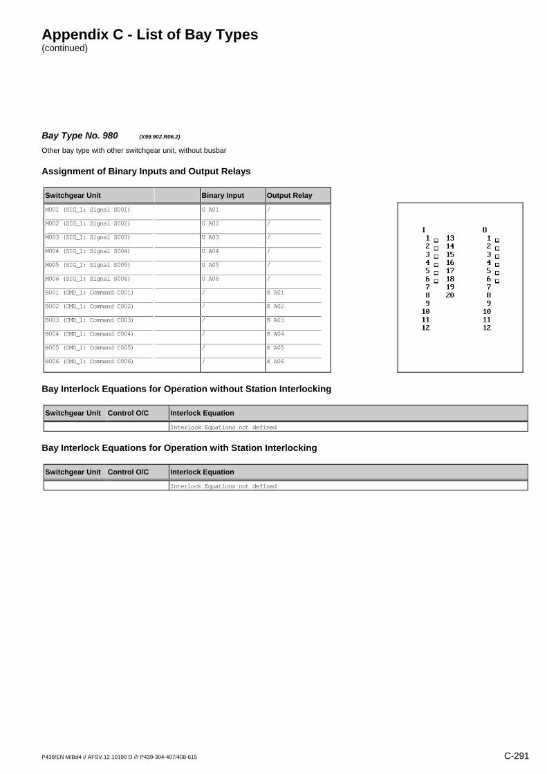
Appendix C - List of Bay Types (continued)
P439/EN M/Bd4 // AFSV.12.10190 D /// P439-304-407/408-615 C-291
Bay Type No. 980 (X99.902.R06.2) Other bay type with other switchgear unit, without busbar
Assignment of Binary Inputs and Output Relays
Switchgear Unit Binary Input Output Relay
M001 (SIG_1: Signal S001) M002 (SIG_1: Signal S002) M003 (SIG_1: Signal S003) M004 (SIG_1: Signal S004) M005 (SIG_1: Signal S005) M006 (SIG_1: Signal S006) B001 (CMD_1: Command C001) B002 (CMD_1: Command C002) B003 (CMD_1: Command C003) B004 (CMD_1: Command C004) B005 (CMD_1: Command C005) B006 (CMD_1: Command C006)
U A01 U A02 U A03 U A04 U A05 U A06 / / / / / /
/ / / / / / K A01 K A02 K A03 K A04 K A05 K A06
Bay Interlock Equations for Operation without Station Interlocking
Switchgear Unit Control O/C Interlock Equation
Interlock Equations not defined
Bay Interlock Equations for Operation with Station Interlocking
Switchgear Unit Control O/C Interlock Equation
Interlock Equations not defined
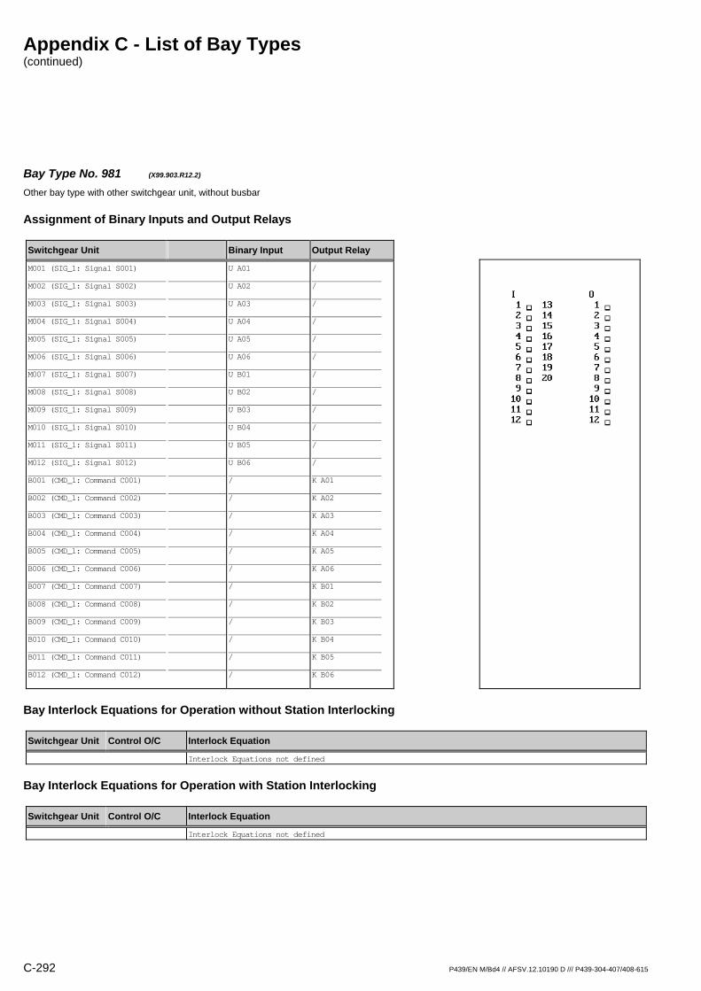
Appendix C - List of Bay Types (continued)
C-292 P439/EN M/Bd4 // AFSV.12.10190 D /// P439-304-407/408-615
Bay Type No. 981 (X99.903.R12.2) Other bay type with other switchgear unit, without busbar
Assignment of Binary Inputs and Output Relays
Switchgear Unit Binary Input Output Relay
M001 (SIG_1: Signal S001) M002 (SIG_1: Signal S002) M003 (SIG_1: Signal S003) M004 (SIG_1: Signal S004) M005 (SIG_1: Signal S005) M006 (SIG_1: Signal S006) M007 (SIG_1: Signal S007) M008 (SIG_1: Signal S008) M009 (SIG_1: Signal S009) M010 (SIG_1: Signal S010) M011 (SIG_1: Signal S011) M012 (SIG_1: Signal S012) B001 (CMD_1: Command C001) B002 (CMD_1: Command C002) B003 (CMD_1: Command C003) B004 (CMD_1: Command C004) B005 (CMD_1: Command C005) B006 (CMD_1: Command C006) B007 (CMD_1: Command C007) B008 (CMD_1: Command C008) B009 (CMD_1: Command C009) B010 (CMD_1: Command C010) B011 (CMD_1: Command C011) B012 (CMD_1: Command C012)
U A01 U A02 U A03 U A04 U A05 U A06 U B01 U B02 U B03 U B04 U B05 U B06 / / / / / / / / / / / /
/ / / / / / / / / / / / K A01 K A02 K A03 K A04 K A05 K A06 K B01 K B02 K B03 K B04 K B05 K B06
Bay Interlock Equations for Operation without Station Interlocking
Switchgear Unit Control O/C Interlock Equation
Interlock Equations not defined
Bay Interlock Equations for Operation with Station Interlocking
Switchgear Unit Control O/C Interlock Equation
Interlock Equations not defined
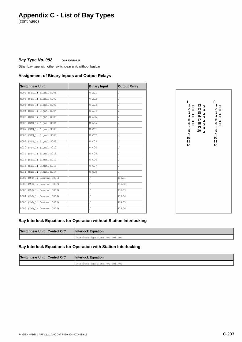
Appendix C - List of Bay Types (continued)
P439/EN M/Bd4 // AFSV.12.10190 D /// P439-304-407/408-615 C-293
Bay Type No. 982 (X99.904.R06.2) Other bay type with other switchgear unit, without busbar
Assignment of Binary Inputs and Output Relays
Switchgear Unit Binary Input Output Relay
M001 (SIG_1: Signal S001) M002 (SIG_1: Signal S002) M003 (SIG_1: Signal S003) M004 (SIG_1: Signal S004) M005 (SIG_1: Signal S005) M006 (SIG_1: Signal S006) M007 (SIG_1: Signal S007) M008 (SIG_1: Signal S008) M009 (SIG_1: Signal S009) M010 (SIG_1: Signal S010) M011 (SIG_1: Signal S011) M012 (SIG_1: Signal S012) M013 (SIG_1: Signal S013) M014 (SIG_1: Signal S014) B001 (CMD_1: Command C001) B002 (CMD_1: Command C002) B003 (CMD_1: Command C003) B004 (CMD_1: Command C004) B005 (CMD_1: Command C005) B006 (CMD_1: Command C006)
U A01 U A02 U A03 U A04 U A05 U A06 U C01 U C02 U C03 U C04 U C05 U C06 U C07 U C08 / / / / / /
/ / / / / / / / / / / / / / K A01 K A02 K A03 K A04 K A05 K A06
Bay Interlock Equations for Operation without Station Interlocking
Switchgear Unit Control O/C Interlock Equation
Interlock Equations not defined
Bay Interlock Equations for Operation with Station Interlocking
Switchgear Unit Control O/C Interlock Equation
Interlock Equations not defined
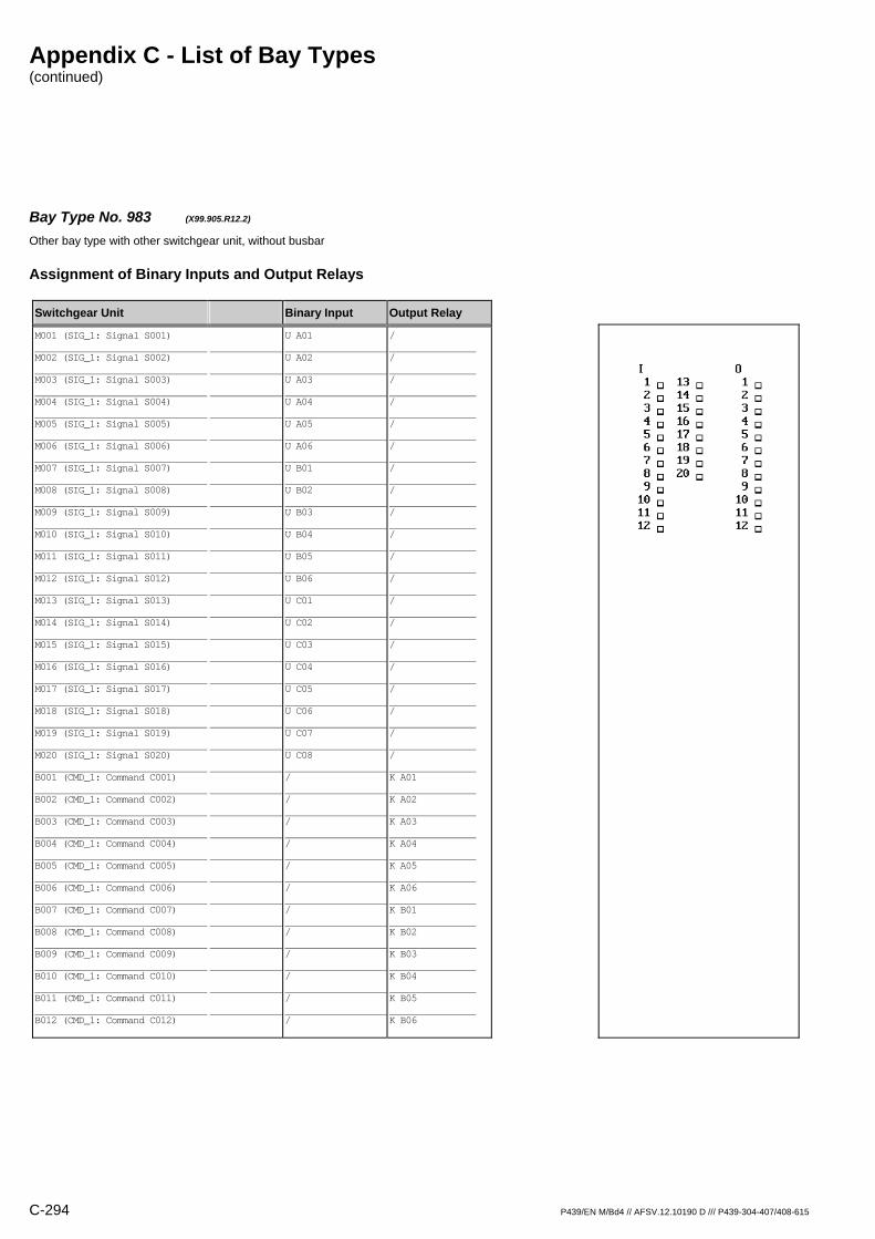
Appendix C - List of Bay Types (continued)
C-294 P439/EN M/Bd4 // AFSV.12.10190 D /// P439-304-407/408-615
Bay Type No. 983 (X99.905.R12.2) Other bay type with other switchgear unit, without busbar
Assignment of Binary Inputs and Output Relays
Switchgear Unit Binary Input Output Relay
M001 (SIG_1: Signal S001) M002 (SIG_1: Signal S002) M003 (SIG_1: Signal S003) M004 (SIG_1: Signal S004) M005 (SIG_1: Signal S005) M006 (SIG_1: Signal S006) M007 (SIG_1: Signal S007) M008 (SIG_1: Signal S008) M009 (SIG_1: Signal S009) M010 (SIG_1: Signal S010) M011 (SIG_1: Signal S011) M012 (SIG_1: Signal S012) M013 (SIG_1: Signal S013) M014 (SIG_1: Signal S014) M015 (SIG_1: Signal S015) M016 (SIG_1: Signal S016) M017 (SIG_1: Signal S017) M018 (SIG_1: Signal S018) M019 (SIG_1: Signal S019) M020 (SIG_1: Signal S020) B001 (CMD_1: Command C001) B002 (CMD_1: Command C002) B003 (CMD_1: Command C003) B004 (CMD_1: Command C004) B005 (CMD_1: Command C005) B006 (CMD_1: Command C006) B007 (CMD_1: Command C007) B008 (CMD_1: Command C008) B009 (CMD_1: Command C009) B010 (CMD_1: Command C010) B011 (CMD_1: Command C011) B012 (CMD_1: Command C012)
U A01 U A02 U A03 U A04 U A05 U A06 U B01 U B02 U B03 U B04 U B05 U B06 U C01 U C02 U C03 U C04 U C05 U C06 U C07 U C08 / / / / / / / / / / / /
/ / / / / / / / / / / / / / / / / / / / K A01 K A02 K A03 K A04 K A05 K A06 K B01 K B02 K B03 K B04 K B05 K B06
Appendix C - List of Bay Types (continued)
P439/EN M/Bd4 // AFSV.12.10190 D /// P439-304-407/408-615 C-295
Bay Interlock Equations for Operation without Station Interlocking
Switchgear Unit Control O/C Interlock Equation
Interlock Equations not defined
Bay Interlock Equations for Operation with Station Interlocking
Switchgear Unit Control O/C Interlock Equation
Interlock Equations not defined
Appendix C - List of Bay Types (continued)
C-296 P439/EN M/Bd4 // AFSV.12.10190 D /// P439-304-407/408-615
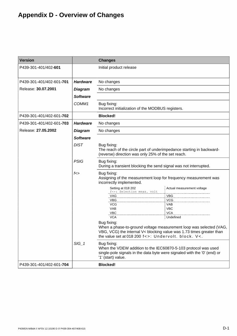
Appendix D - Overview of Changes
P439/EN M/Bd4 // AFSV.12.10190 D /// P439-304-407/408-615 D-1
Version Changes
P439-301-401/402-601 Initial product release
Hardware No changes P439-301-401/402-601-701
Release: 30.07.2001 Diagram No changes
Software
COMM1 Bug fixing: Incorrect initialization of the MODBUS registers.
P439-301-401/402-601-702 Blocked!
Hardware No changes P439-301-401/402-601-703
Release: 27.05.2002 Diagram No changes
Software
DIST Bug fixing: The reach of the circle part of underimpedance starting in backward- (reverse) direction was only 25% of the set reach.
PSIG Bug fixing: During a transient blocking the send signal was not interrupted.
f<> Bug fixing: Assigning of the measurement loop for frequency measurement was incorrectly implemented.
Setting at 018 202 f<>: Selection meas. volt
Actual measurement voltage
VAG VBG VBG VCG VCG VAB VAB VBC VBC VCA VCA Undefined
Bug fixing: When a phase-to-ground voltage measurement loop was selected (VAG, VBG, VCG) the internal V< blocking value was 1.73 times greater than the value set at 018 200 f < > : U n d e r v o l t . b l o c k . V < .
SIG_1 Bug fixing: When the VDEW addition to the IEC60870-5-103 protocol was used single-pole signals in the data byte were signaled with the '0' (end) or '1' (start) value.
P439-301-401/402-601-704 Blocked!
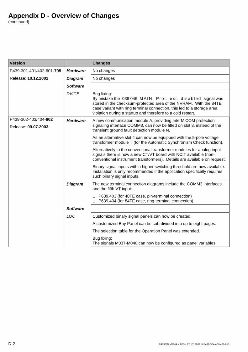
Appendix D - Overview of Changes (continued)
D-2 P439/EN M/Bd4 // AFSV.12.10190 D /// P439-304-407/408-615
Version Changes
Hardware No changes P439-301-401/402-601-705
Release: 10.12.2002 Diagram No changes
Software
DVICE Bug fixing: By mistake the 038 046 M A I N : P r o t . e x t . d i s a b l e d signal was stored in the checksum-protected area of the NVRAM. With the 84TE case variant with ring terminal connection, this led to a storage area violation during a startup and therefore to a cold restart.
Hardware A new communication module A, providing InterMiCOM protection signaling interface COMM3, can now be fitted on slot 3, instead of the transient ground fault detection module N.
As an alternative slot 4 can now be equipped with the 5-pole voltage transformer module T (for the Automatic Synchronism Check function).
Alternatively to the conventional transformer modules for analog input signals there is now a new CT/VT board with NCIT available (non-conventional instrument transformers). Details are available on request.
Binary signal inputs with a higher switching threshold are now available. Installation is only recommended if the application specifically requires such binary signal inputs.
P439-302-403/404-602
Release: 09.07.2003
Diagram The new terminal connection diagrams include the COMM3 interfaces and the fifth VT input:
P639.403 (for 40TE case, pin-terminal connection) P639.404 (for 84TE case, ring-terminal connection)
Software
LOC Customized binary signal panels can now be created.
A customized Bay Panel can be sub-divided into up to eight pages.
The selection table for the Operation Panel was extended.
Bug fixing: The signals M037-M040 can now be configured as panel variables.
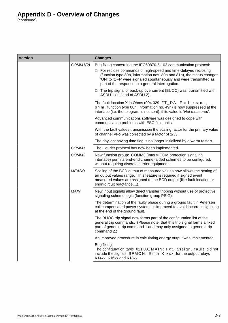
Appendix D - Overview of Changes (continued)
P439/EN M/Bd4 // AFSV.12.10190 D /// P439-304-407/408-615 D-3
Version Changes
COMM1(2) Bug fixing concerning the IEC60870-5-103 communication protocol: For reclose commands of high-speed and time-delayed reclosing
(function type 80h, information nos. 80h and 81h), the status changes 'ON' to 'OFF' were signaled spontaneously and were transmitted as part of the response to a general interrogation.
The trip signal of back-up overcurrent (BUOC) was transmitted with ASDU 1 (instead of ASDU 2).
The fault location X in Ohms (004 029 F T _ D A : F a u l t r e a c t . , p r i m . function type 80h, information no. 49h) is now suppressed at the interface (i.e. the telegram is not sent), if its value is 'Not measured‘.
Advanced communications software was designed to cope with communication problems with ESC field units.
With the fault values transmission the scaling factor for the primary value of channel VNG was corrected by a factor of 1/√3.
The daylight saving time flag is no longer initialized by a warm restart.
COMM1 The Courier protocol has now been implemented.
COMM3 New function group: COMM3 (InterMiCOM protection signaling interface) permits end-end channel-aided schemes to be configured, without requiring discrete carrier equipment.
MEASO Scaling of the BCD output of measured values now allows the setting of an output values range. This feature is required if signed event measured values are assigned to the BCD output (like fault location or short-circuit reactance,...).
MAIN New input signals allow direct transfer tripping without use of protective signaling scheme logic (function group PSIG).
The determination of the faulty phase during a ground fault in Petersen coil compensated power systems is improved to avoid incorrect signaling at the end of the ground fault.
The BUOC trip signal now forms part of the configuration list of the general trip commands. (Please note, that this trip signal forms a fixed part of general trip command 1 and may only assigned to general trip command 2.)
An improved procedure in calculating energy output was implemented.
Bug fixing: The configuration table 021 031 M A I N : F c t . a s s i g n . f a u l t did not include the signals S F M O N : E r r o r K x x x for the output relays K14xx, K16xx and K18xx.
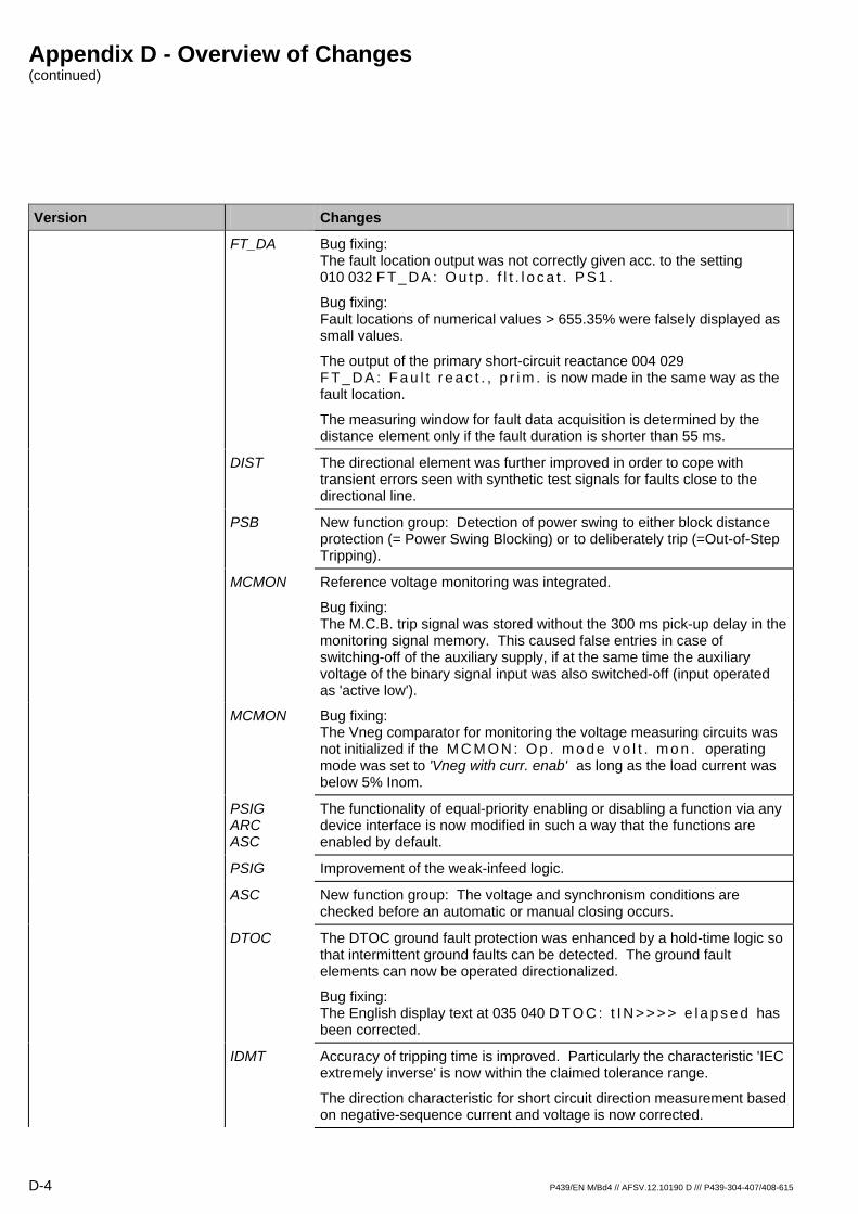
Appendix D - Overview of Changes (continued)
D-4 P439/EN M/Bd4 // AFSV.12.10190 D /// P439-304-407/408-615
Version Changes
FT_DA Bug fixing: The fault location output was not correctly given acc. to the setting 010 032 F T _ D A : O u t p . f l t . l o c a t . P S 1 .
Bug fixing: Fault locations of numerical values > 655.35% were falsely displayed as small values.
The output of the primary short-circuit reactance 004 029 F T _ D A : F a u l t r e a c t . , p r i m . is now made in the same way as the fault location.
The measuring window for fault data acquisition is determined by the distance element only if the fault duration is shorter than 55 ms.
DIST The directional element was further improved in order to cope with transient errors seen with synthetic test signals for faults close to the directional line.
PSB New function group: Detection of power swing to either block distance protection (= Power Swing Blocking) or to deliberately trip (=Out-of-Step Tripping).
MCMON Reference voltage monitoring was integrated.
Bug fixing: The M.C.B. trip signal was stored without the 300 ms pick-up delay in the monitoring signal memory. This caused false entries in case of switching-off of the auxiliary supply, if at the same time the auxiliary voltage of the binary signal input was also switched-off (input operated as 'active low').
MCMON Bug fixing: The Vneg comparator for monitoring the voltage measuring circuits was not initialized if the M C M O N : O p . m o d e v o l t . m o n . operating mode was set to 'Vneg with curr. enab' as long as the load current was below 5% Inom.
PSIG ARC ASC
The functionality of equal-priority enabling or disabling a function via any device interface is now modified in such a way that the functions are enabled by default.
PSIG Improvement of the weak-infeed logic.
ASC New function group: The voltage and synchronism conditions are checked before an automatic or manual closing occurs.
DTOC The DTOC ground fault protection was enhanced by a hold-time logic so that intermittent ground faults can be detected. The ground fault elements can now be operated directionalized.
Bug fixing: The English display text at 035 040 D T O C : t I N > > > > e l a p s e d has been corrected.
IDMT Accuracy of tripping time is improved. Particularly the characteristic 'IEC extremely inverse' is now within the claimed tolerance range.
The direction characteristic for short circuit direction measurement based on negative-sequence current and voltage is now corrected.

Appendix D - Overview of Changes (continued)
P439/EN M/Bd4 // AFSV.12.10190 D /// P439-304-407/408-615 D-5
Version Changes
f<> Measurements of minimum frequency during an underfrequency situation and maximum frequency during an overfrequency situation have been added.
TGFD The setting range for 016 042 T G F D : I N , p > is extended to 0.03 Inom.
The pick-up delay of the measuring circuit monitoring signal at 093 094 S F M O N : T G F D m o n . t r i g g e r e d is now increased from 5 s to 65 s.
LOGIC Bug fixing: The time dependent logic outputs 042 033 L O G I C : O u t p u t x ( t ) , with x=1 to 32) were reset for a short period during parameter subset selection.
SIG_1 Bug fixing: A concurrent use of signals M001 and M033 was not possible.
DEVxx Bug fixing: The SIN-Byte was not supported in the transmission per IEC60850-5-103/VDEW mode.
CMD_1 Single commands, created with the bay editor from the PC Access Software MiCOM S1, can now also be assigned to output relays on the output module X (6xO) in slot 10 (with 40TE cases) or slot 18 (with 84TE cases).
Hardware No changes P439-302-403/404-602-706 Release: 11.12.2003 Diagram No changes
Software
LOC Bug fixing: Selecting (user defined) switchgear units without device designation is now made possible.
COMM1 Bug fixing concerning various communication protocols:
DNP3: Multiple telegrams are prevented.
The protocol per IEC 60850-5-101 incorrectly transmitted negative operating values.
COMM1 COMM2 PC
Change of the type characteristic for the measured operating values in the IEC 60870-5-103 communication protocol from F2 to F8 hex.
MAIN Bug fixing:
When a warm restart occurred with version -602 the primary nominal voltages V and Vref were initialized with their default values.
With version -602 the setting for the close command pulse time was ignored; the close command pulse time was fixed permanently at 50 ms.
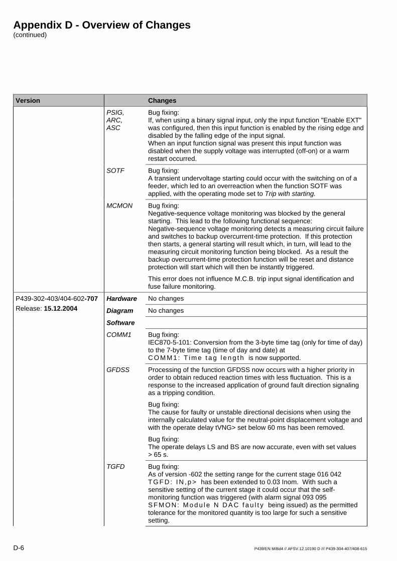
Appendix D - Overview of Changes (continued)
D-6 P439/EN M/Bd4 // AFSV.12.10190 D /// P439-304-407/408-615
Version Changes
PSIG, ARC, ASC
Bug fixing: If, when using a binary signal input, only the input function "Enable EXT" was configured, then this input function is enabled by the rising edge and disabled by the falling edge of the input signal. When an input function signal was present this input function was disabled when the supply voltage was interrupted (off-on) or a warm restart occurred.
SOTF Bug fixing: A transient undervoltage starting could occur with the switching on of a feeder, which led to an overreaction when the function SOTF was applied, with the operating mode set to Trip with starting.
MCMON Bug fixing: Negative-sequence voltage monitoring was blocked by the general starting. This lead to the following functional sequence: Negative-sequence voltage monitoring detects a measuring circuit failure and switches to backup overcurrent-time protection. If this protection then starts, a general starting will result which, in turn, will lead to the measuring circuit monitoring function being blocked. As a result the backup overcurrent-time protection function will be reset and distance protection will start which will then be instantly triggered.
This error does not influence M.C.B. trip input signal identification and fuse failure monitoring.
Hardware No changes P439-302-403/404-602-707 Release: 15.12.2004 Diagram No changes
Software
COMM1 Bug fixing: IEC870-5-101: Conversion from the 3-byte time tag (only for time of day) to the 7-byte time tag (time of day and date) at C O M M 1 : T i m e t a g l e n g t h is now supported.
GFDSS Processing of the function GFDSS now occurs with a higher priority in order to obtain reduced reaction times with less fluctuation. This is a response to the increased application of ground fault direction signaling as a tripping condition.
Bug fixing: The cause for faulty or unstable directional decisions when using the internally calculated value for the neutral-point displacement voltage and with the operate delay tVNG> set below 60 ms has been removed.
Bug fixing: The operate delays LS and BS are now accurate, even with set values > 65 s.
TGFD Bug fixing: As of version -602 the setting range for the current stage 016 042 T G F D : I N , p > has been extended to 0.03 Inom. With such a sensitive setting of the current stage it could occur that the self-monitoring function was triggered (with alarm signal 093 095 S F M O N : M o d u l e N D A C f a u l t y being issued) as the permitted tolerance for the monitored quantity is too large for such a sensitive setting.
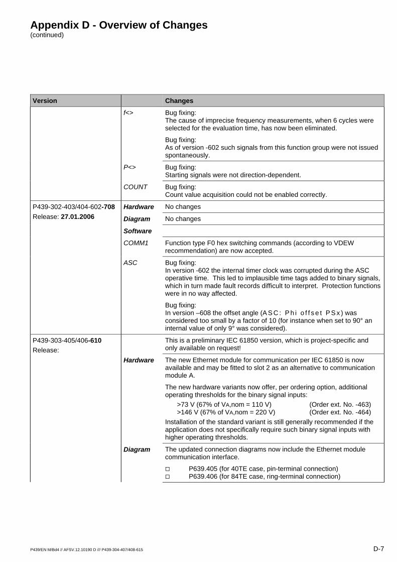
Appendix D - Overview of Changes (continued)
P439/EN M/Bd4 // AFSV.12.10190 D /// P439-304-407/408-615 D-7
Version Changes
f<> Bug fixing: The cause of imprecise frequency measurements, when 6 cycles were selected for the evaluation time, has now been eliminated.
Bug fixing: As of version -602 such signals from this function group were not issued spontaneously.
P<> Bug fixing: Starting signals were not direction-dependent.
COUNT Bug fixing: Count value acquisition could not be enabled correctly.
Hardware No changes P439-302-403/404-602-708 Release: 27.01.2006 Diagram No changes
Software
COMM1 Function type F0 hex switching commands (according to VDEW recommendation) are now accepted.
ASC Bug fixing: In version -602 the internal timer clock was corrupted during the ASC operative time. This led to implausible time tags added to binary signals, which in turn made fault records difficult to interpret. Protection functions were in no way affected.
Bug fixing: In version –608 the offset angle (A S C : P h i o f f s e t P S x ) was considered too small by a factor of 10 (for instance when set to 90° an internal value of only 9° was considered).
This is a preliminary IEC 61850 version, which is project-specific and only available on request!
P439-303-405/406-610 Release:
Hardware The new Ethernet module for communication per IEC 61850 is now available and may be fitted to slot 2 as an alternative to communication module A.
The new hardware variants now offer, per ordering option, additional operating thresholds for the binary signal inputs:
>73 V (67% of VA,nom = 110 V) (Order ext. No. -463) >146 V (67% of VA,nom = 220 V) (Order ext. No. -464)
Installation of the standard variant is still generally recommended if the application does not specifically require such binary signal inputs with higher operating thresholds.
Diagram The updated connection diagrams now include the Ethernet module communication interface.
P639.405 (for 40TE case, pin-terminal connection) P639.406 (for 84TE case, ring-terminal connection)

Appendix D - Overview of Changes (continued)
D-8 P439/EN M/Bd4 // AFSV.12.10190 D /// P439-304-407/408-615
Version Changes
Software
LOC Extensive expansion of the parameter selection at 080 110 L O C : A s s i g n m e n t r e a d k e y . Instead of selecting only one assigned protocol by pressing the READ key there are now up to 16 different addresses assigned which can be selected by pressing the READ key more than once in succession (menu jump function).
COMM1 Time stamping of status signals from external devices has been adapted to the DNP3 protocol.
Bug fixing: A change of a communication parameter will no longer lead to a sporadic warm restart of the device, when the Courier protocol is used.
COMM1/ COMM2
With the IEC 60870-5-103 protocol, the selection of measured operating values has been extended for the cyclic ILS telegram (see MAIN, new measured operating values).
COMM2 It is now possible to select by setting 103 203 C O M M 2 : P o s i t i v e a c k n . F a u l t whether a fault read out at COMM2 is to be acknowledged positively and consequently deleted from the fault overview at the COMM2/PC interface or not.
IEC Initial implementation of the IEC 61850 communication protocol.
GSSE In conjunction with the IEC 61850 communication protocol a communication procedure has been implemented that is compatible with previous UCA2 GOOSE for the exchange of binary information within an Ethernet network section.
GOOSE For the exchange of binary information in an Ethernet network section the IEC 61850 communication procedure (IEC-GOOSE) has been implemented.

Appendix D - Overview of Changes (continued)
P439/EN M/Bd4 // AFSV.12.10190 D /// P439-304-407/408-615 D-9
Version Changes
SFMON A number of device bugs previously lead to a blocking with the second entry to the monitoring signal memory (i.e. if the recurring fault was already stored in the monitoring signal memory – see Chapter 10 in the Technical Manual). This reaction was modified such that device blocking will only occur if a renewed appearance of the same device fault lies within a set "memory retention time" at 021 018 S F M O N : M o n . s i g . r e t e n t i o n . This makes it possible to tolerate sporadic faults, resulting from control actions, without having to clear the monitoring signal memory in the interim.
The significance of the time stamp was modified to accommodate this new feature. The time stamp now represents the last appearance of the fault.
In the course of platform harmonization the configuration table of the user defined alarm condition has been supplemented by the instantaneous outputs 30...32 and the timed outputs 30...32 (t) of the programmable LOGIC:
098 053 SFMON: Ou tpu t 30 ↔ 042 090 LOGIC: Ou tpu t 30 098 054 SFMON: Ou tpu t 30 ( t ) ↔ 042 091 LOGIC: Ou tpu t 30 ( t ) 098 055 SFMON: Ou tpu t 31 ↔ 042 092 LOGIC: Ou tpu t 31 098 056 SFMON: Ou tpu t 31 ( t ) ↔ 042 093 LOGIC: Ou tpu t 31 ( t ) 098 057 SFMON: Ou tpu t 32 ↔ 042 094 LOGIC: Ou tpu t 32 098 058 SFMON: Ou tpu t 32 ( t ) ↔ 042 095 LOGIC: Ou tpu t 32 ( t )
These signals can be used to create an alarm signal under complex application conditions. This signaling has no influence on the device's operation (i.e. no warm restart or blocking).
The following alarm signals relate to the communication module that supports the protocol per IEC 60870-5-103 only:
093 070 S F M O N : M o d u l e A D P R f a u l t y 093 071 S F M O N : M o d u l e A R A M f a u l t y
This communication module cannot be fitted to the P439 and the signals have therefore been removed.
FT_RC The duration of the disturbance record is limited to 1 minute so as to avoid a record of an endless disturbance. The 002 002 F T _ R C : R e c o r d . t r i g a c t i v e signal shows that a fault-recording trigger is present.
The 036 050 A R C : B l o c k i n g E X T signal is now stored in the fault record (previously only the resulting signal 004 069 A R C : B l o c k e d was recorded).
MEASI Open-circuit monitoring of the 20 mA input and the "PT 100" input has been improved.

Appendix D - Overview of Changes (continued)
D-10 P439/EN M/Bd4 // AFSV.12.10190 D /// P439-304-407/408-615
Version Changes
MAIN Parameters, which could previously only be set in the "General Functions" branch of the menu tree, have been transferred to the parameter subsets.
M A I N : N e u t r . p t . t r e a t . P S x M A I N : P h a s e p r i o . 2 p G P S x M A I N : T r a n s f e r f o r 1 p P S x M A I N : O p . m o d e r u s h r . P S x M A I N : I > l i f t r u s h r . P S x M A I N : I ( 2 * f n ) / I ( f n ) P S x
With this improvement it is now possible to consider operational changes in the system's neutral grounding by selecting the appropriate parameter subset.
The CB close time (e.g. time from close command to closing of CB contacts) can now be set at 000 032 M A I N : t C B , c l o s e . This time duration may be applied in the function ASC for the new functionality "switch on at point of synchronism".
The primary source for synchronizing the date and time can now be selected. Available are COMM1, COMM2/PC, IRIG-B or a binary input for minute signal pulses. A backup source may additionally be selected:
103 210 M A I N : P r i m . S o u r c e T i m e S y n c 103 211 M A I N : B a c k u p S o u r c e T i m e S y n c
The following per unit measured operating values have been added:
004 070 M A I N : F r e q u e n c y f p . u . 005 072 M A I N : A n g l e V P G / I N p . u . 005 073 M A I N : L o a d a n g l e p h i A p . u 005 074 M A I N : L o a d a n g l e p h i B p . u 005 075 M A I N : L o a d a n g l e p h i C p . u 005 076 M A I N : A n g l e p h i N p . u .
The parameter 010 049 M A I N : R o t a r y f i e l d was renamed to 010 049 M A I N : P h a s e s e q u . In addition the parameter selection for clockwise and anticlockwise was also changed to A-B-C and A-C-B.
For bay control function signals detected via binary signal inputs and conditioned with debouncing it is now possible to select whether the time tag for the signal is to be issued after debouncing (or when the first pulse edge is detected). The setting 221 083 M A I N : T i m e T a g A f t e r D e b o u n c e is provided for this purpose.
DIST The ground fault starting condition has been made settable by an 'OR'-linked or an 'AND'-linked condition of the IN> and VNG> thresholds, if the system star point is low-impedance grounded (setting at M A I N : G r o u n d s t a r t i n g P S x ).
The enable logic for the sensitive double earth fault detection has been enhanced such that now the base point current must be enabled in one of the two phases for which the undervoltage condition is met.
Bug fixing: Correction of the angle error which appeared when the system frequency deviated from the nominal frequency fnom = 60 Hz and had an incorrect value differing by a factor of 5/6.
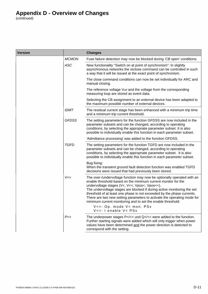
Appendix D - Overview of Changes (continued)
P439/EN M/Bd4 // AFSV.12.10190 D /// P439-304-407/408-615 D-11
Version Changes
MCMON Fuse failure detection may now be blocked during 'CB open' conditions.
ASC New functionality "Switch on at point of synchronism": In slightly asynchronous networks the reclose command can be controlled in such a way that it will be issued at the exact point of synchronism.
The close command conditions can now be set individually for ARC and manual closing.
The reference voltage Vref and the voltage from the corresponding measuring loop are stored as event data.
Selecting the CB assignment to an external device has been adapted to the maximum possible number of external devices.
IDMT The residual current stage has been enhanced with a minimum trip time and a minimum trip current threshold.
GFDSS The setting parameters for the function GFDSS are now included in the parameter subsets and can be changed, according to operating conditions, by selecting the appropriate parameter subset. It is also possible to individually enable this function in each parameter subset.
'Admittance processing' was added to the function GFDSS.
TGFD The setting parameters for the function TGFD are now included in the parameter subsets and can be changed, according to operating conditions, by selecting the appropriate parameter subset. It is also possible to individually enable this function in each parameter subset.
Bug fixing: When the transient ground fault detection function was enabled TGFD decisions were issued that had previously been stored.
V<> The over-/undervoltage function may now be optionally operated with an enable threshold based on the minimum current monitor for the undervoltage stages (V<, V<<, Vpos<, Vpos<<). The undervoltage stages are blocked if during active monitoring the set threshold of at least one phase is not exceeded by the phase currents. There are two new setting parameters to activate the operating mode for minimum current monitoring and to set the enable threshold:
V < > : O p . m o d e V < m o n . P S x V < > : I e n a b l e V < P S x
P<> The underpower stages P</<< und Q</<< were added to the function. Further starting signals were added which will only trigger when power values have been determined and the power direction is detected to correspond with the setting.

Appendix D - Overview of Changes (continued)
D-12 P439/EN M/Bd4 // AFSV.12.10190 D /// P439-304-407/408-615
Version Changes
CBF The complete revision of the circuit breaker failure protection function now includes a current reset criterion.
CBM Function circuit breaker monitoring (CBM) has been added.
P439-303-405/406-611 Hardware No changes
Release: Diagram No changes
Software
DVICE The basic software for the device has been adapted to support a detachable HMI.
IEC A settable VLA identifier has been implemented.
The IEC data model has been extended and harmonized.
The settable IED name now precedes the LD name.
Bug fixing: A fault could occur when the device was overloaded with too many switching commands. Bug notice: With versions -610 and -611 it is not possible to enter GOOSE events into the interlocking logic.
P439-303-405/406-612 Hardware No changes
Release: 06.12.2006 Diagram No changes
Software
COMM1 The upgraded communications software 3.18 is now implemented. Various small bugs have been fixed in communication protocols per IEC 60870-5-101 and MODBUS.
IEC Bug fixing: Inactivity monitoring has been modified so as to remove the break in the client-server communications link after approximately 49 days for about 20 minutes. Note: GOOSE and GSSE were not affected by this break in the client-server communications link.
Bug fixing: If communication was interrupted during control access via the Ethernet interface using the operating program MiCOM S1, renewed control access was only possible after a warm restart of the protection and control unit.
Bug fixing: If a 'Select' or 'Operate' command for an external device, in which the interlock bit had been set, was sent from a client to the protection and control unit it could occur that such a command was rejected.
GOOSE For the exchange of binary information in an Ethernet network section the IEC 61850 communication procedure (IEC-GOOSE) has been implemented.
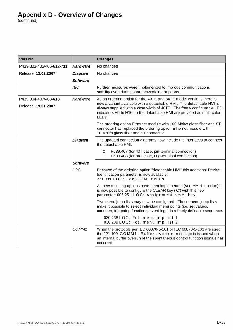
Appendix D - Overview of Changes (continued)
P439/EN M/Bd4 // AFSV.12.10190 D /// P439-304-407/408-615 D-13
Version Changes
P439-303-405/406-612-711 Hardware No changes
Release: 13.02.2007 Diagram No changes
Software
IEC Further measures were implemented to improve communications stability even during short network interruptions.
P439-304-407/408-613
Release: 19.01.2007
Hardware As an ordering option for the 40TE and 84TE model versions there is now a variant available with a detachable HMI. The detachable HMI is always supplied with a case width of 40TE. The freely configurable LED indicators H4 to H16 on the detachable HMI are provided as multi-color LEDs.
The ordering option Ethernet module with 100 Mbit/s glass fiber and ST connector has replaced the ordering option Ethernet module with 10 Mbit/s glass fiber and ST connector.
Diagram The updated connection diagrams now include the interfaces to connect the detachable HMI.
P639.407 (for 40T case, pin-terminal connection) P639.408 (for 84T case, ring-terminal connection)
Software LOC Because of the ordering option "detachable HMI" this additional Device
Identification parameter is now available: 221 099 L O C : L o c a l H M I e x i s t s .
As new resetting options have been implemented (see MAIN function) it is now possible to configure the CLEAR key ('C') with this new parameter: 005 251 L O C : A s s i g n m e n t r e s e t k e y .
Two menu jump lists may now be configured. These menu jump lists make it possible to select individual menu points (i.e. set values, counters, triggering functions, event logs) in a freely definable sequence.
030 238 L O C : F c t . m e n u j m p l i s t 1 030 239 L O C : F c t . m e n u j m p l i s t 2
COMM1 When the protocols per IEC 60870-5-101 or IEC 60870-5-103 are used, the 221 100 C O M M 1 : B u f f e r o v e r r u n message is issued when an internal buffer overrun of the spontaneous control function signals has occurred.
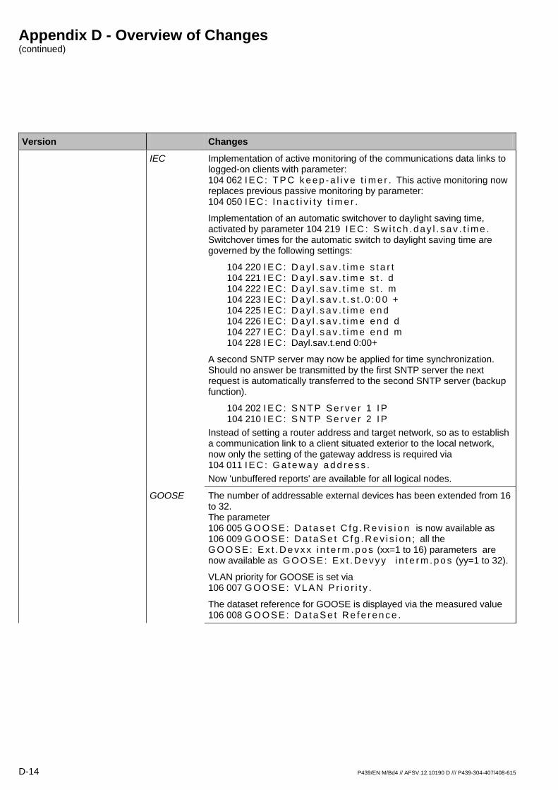
Appendix D - Overview of Changes (continued)
D-14 P439/EN M/Bd4 // AFSV.12.10190 D /// P439-304-407/408-615
Version Changes
IEC Implementation of active monitoring of the communications data links to logged-on clients with parameter: 104 062 I E C : T P C k e e p - a l i v e t i m e r . This active monitoring now replaces previous passive monitoring by parameter: 104 050 I E C : I n a c t i v i t y t i m e r .
Implementation of an automatic switchover to daylight saving time, activated by parameter 104 219 I E C : S w i t c h . d a y l . s a v . t i m e . Switchover times for the automatic switch to daylight saving time are governed by the following settings:
104 220 I E C : D a y l . s a v . t i m e s t a r t 104 221 I E C : D a y l . s a v . t i m e s t . d 104 222 I E C : D a y l . s a v . t i m e s t . m 104 223 I E C : D a y l . s a v . t . s t . 0 : 0 0 + 104 225 I E C : D a y l . s a v . t i m e e n d 104 226 I E C : D a y l . s a v . t i m e e n d d 104 227 I E C : D a y l . s a v . t i m e e n d m 104 228 I E C : Dayl.sav.t.end 0:00+
A second SNTP server may now be applied for time synchronization. Should no answer be transmitted by the first SNTP server the next request is automatically transferred to the second SNTP server (backup function).
104 202 I E C : S N T P S e r v e r 1 I P 104 210 I E C : S N T P S e r v e r 2 I P
Instead of setting a router address and target network, so as to establish a communication link to a client situated exterior to the local network, now only the setting of the gateway address is required via 104 011 I E C : G a t e w a y a d d r e s s . Now 'unbuffered reports' are available for all logical nodes.
GOOSE The number of addressable external devices has been extended from 16 to 32. The parameter 106 005 G O O S E : D a t a s e t C f g . R e v i s i o n is now available as 106 009 G O O S E : D a t a S e t C f g . R e v i s i o n ; all the G O O S E : E x t . D e v x x i n t e r m . p o s (xx=1 to 16) parameters are now available as G O O S E : E x t . D e v y y i n t e r m . p o s (yy=1 to 32).
VLAN priority for GOOSE is set via 106 007 G O O S E : V L A N P r i o r i t y .
The dataset reference for GOOSE is displayed via the measured value 106 008 G O O S E : D a t a S e t R e f e r e n c e .
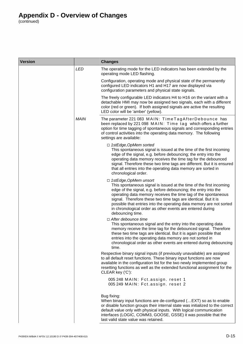
Appendix D - Overview of Changes (continued)
P439/EN M/Bd4 // AFSV.12.10190 D /// P439-304-407/408-615 D-15
Version Changes
LED The operating mode for the LED indicators has been extended by the operating mode LED flashing.
Configuration, operating mode and physical state of the permanently configured LED indicators H1 and H17 are now displayed via configuration parameters and physical state signals.
The freely configurable LED indicators H4 to H16 on the variant with a detachable HMI may now be assigned two signals, each with a different color (red or green). If both assigned signals are active the resulting LED color will be 'amber' (yellow).
MAIN The parameter 221 083 M A I N : T i m e T a g A f t e r D e b o u n c e has been replaced by 221 098 M A I N : T i m e t a g which offers a further option for time tagging of spontaneous signals and corresponding entries of control activities into the operating data memory. The following settings are available:
1stEdge,OpMem sorted This spontaneous signal is issued at the time of the first incoming edge of the signal, e.g. before debouncing; the entry into the operating data memory receives the time tag for the debounced signal. Therefore these two time tags are different. But it is ensured that all entries into the operating data memory are sorted in chronological order.
1stEdge,OpMem unsort This spontaneous signal is issued at the time of the first incoming edge of the signal, e.g. before debouncing; the entry into the operating data memory receives the time tag of the spontaneous signal. Therefore these two time tags are identical. But it is possible that entries into the operating data memory are not sorted in chronological order as other events are entered during debouncing time.
After debounce time This spontaneous signal and the entry into the operating data memory receive the time tag for the debounced signal. Therefore these two time tags are identical. But it is again possible that entries into the operating data memory are not sorted in chronological order as other events are entered during debouncing time.
Respective binary signal inputs (if previously unavailable) are assigned to all default reset functions. These binary input functions are now available in the configuration list for the two newly implemented group resetting functions as well as the extended functional assignment for the CLEAR key ('C'):
005 248 M A I N : F c t . a s s i g n . r e s e t 1 005 249 M A I N : F c t . a s s i g n . r e s e t 2
Bug fixing: When binary input functions are de-configured (…EXT) so as to enable or disable function groups their internal state was initialized to the correct default value only with physical inputs. With logical communication interfaces (LOGIC, COMM3, GOOSE, GSSE) it was possible that the last valid state value was retained.
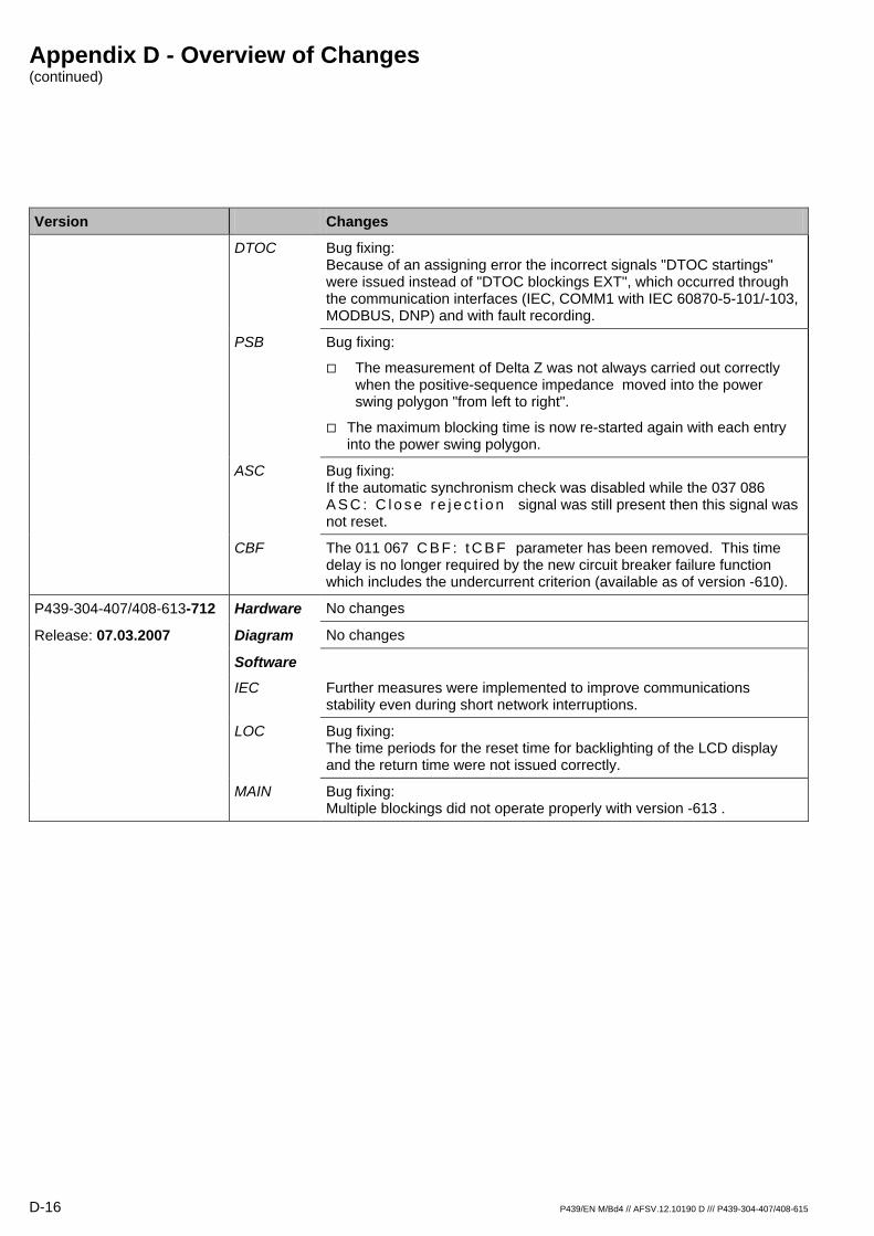
Appendix D - Overview of Changes (continued)
D-16 P439/EN M/Bd4 // AFSV.12.10190 D /// P439-304-407/408-615
Version Changes
DTOC Bug fixing: Because of an assigning error the incorrect signals "DTOC startings" were issued instead of "DTOC blockings EXT", which occurred through the communication interfaces (IEC, COMM1 with IEC 60870-5-101/-103, MODBUS, DNP) and with fault recording.
PSB Bug fixing:
The measurement of Delta Z was not always carried out correctly when the positive-sequence impedance moved into the power swing polygon "from left to right".
The maximum blocking time is now re-started again with each entry into the power swing polygon.
ASC Bug fixing: If the automatic synchronism check was disabled while the 037 086 A S C : C l o s e r e j e c t i o n signal was still present then this signal was not reset.
CBF The 011 067 C B F : t C B F parameter has been removed. This time delay is no longer required by the new circuit breaker failure function which includes the undercurrent criterion (available as of version -610).
P439-304-407/408-613-712 Hardware No changes
Release: 07.03.2007 Diagram No changes
Software
IEC Further measures were implemented to improve communications stability even during short network interruptions.
LOC Bug fixing: The time periods for the reset time for backlighting of the LCD display and the return time were not issued correctly.
MAIN Bug fixing: Multiple blockings did not operate properly with version -613 .
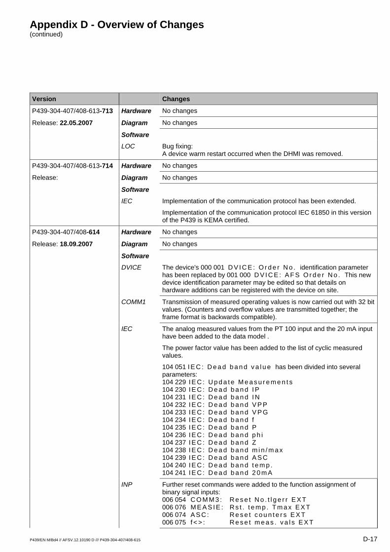
Appendix D - Overview of Changes (continued)
P439/EN M/Bd4 // AFSV.12.10190 D /// P439-304-407/408-615 D-17
Version Changes
P439-304-407/408-613-713 Hardware No changes
Release: 22.05.2007 Diagram No changes
Software
LOC Bug fixing: A device warm restart occurred when the DHMI was removed.
P439-304-407/408-613-714 Hardware No changes
Release: Diagram No changes
Software
IEC Implementation of the communication protocol has been extended.
Implementation of the communication protocol IEC 61850 in this version of the P439 is KEMA certified.
P439-304-407/408-614 Hardware No changes
Release: 18.09.2007 Diagram No changes
Software
DVICE The device's 000 001 D V I C E : O r d e r N o . identification parameter has been replaced by 001 000 D V I C E : A F S O r d e r N o . This new device identification parameter may be edited so that details on hardware additions can be registered with the device on site.
COMM1 Transmission of measured operating values is now carried out with 32 bit values. (Counters and overflow values are transmitted together; the frame format is backwards compatible).
IEC The analog measured values from the PT 100 input and the 20 mA input have been added to the data model .
The power factor value has been added to the list of cyclic measured values.
104 051 I E C : D e a d b a n d v a l u e has been divided into several parameters: 104 229 I E C : U p d a t e M e a s u r e m e n t s 104 230 I E C : D e a d b a n d I P 104 231 I E C : D e a d b a n d I N 104 232 I E C : D e a d b a n d V P P 104 233 I E C : D e a d b a n d V P G 104 234 I E C : D e a d b a n d f 104 235 I E C : D e a d b a n d P 104 236 I E C : D e a d b a n d p h i 104 237 I E C : D e a d b a n d Z 104 238 I E C : D e a d b a n d m i n / m a x 104 239 I E C : D e a d b a n d A S C 104 240 I E C : D e a d b a n d t e m p . 104 241 I E C : D e a d b a n d 2 0 m A
INP Further reset commands were added to the function assignment of binary signal inputs: 006 054 C O M M 3 : R e s e t N o . t l g e r r E X T 006 076 M E A S I E : R s t . t e m p . T m a x E X T 006 074 A S C : R e s e t c o u n t e r s E X T 006 075 f < > : R e s e t m e a s . v a l s E X T
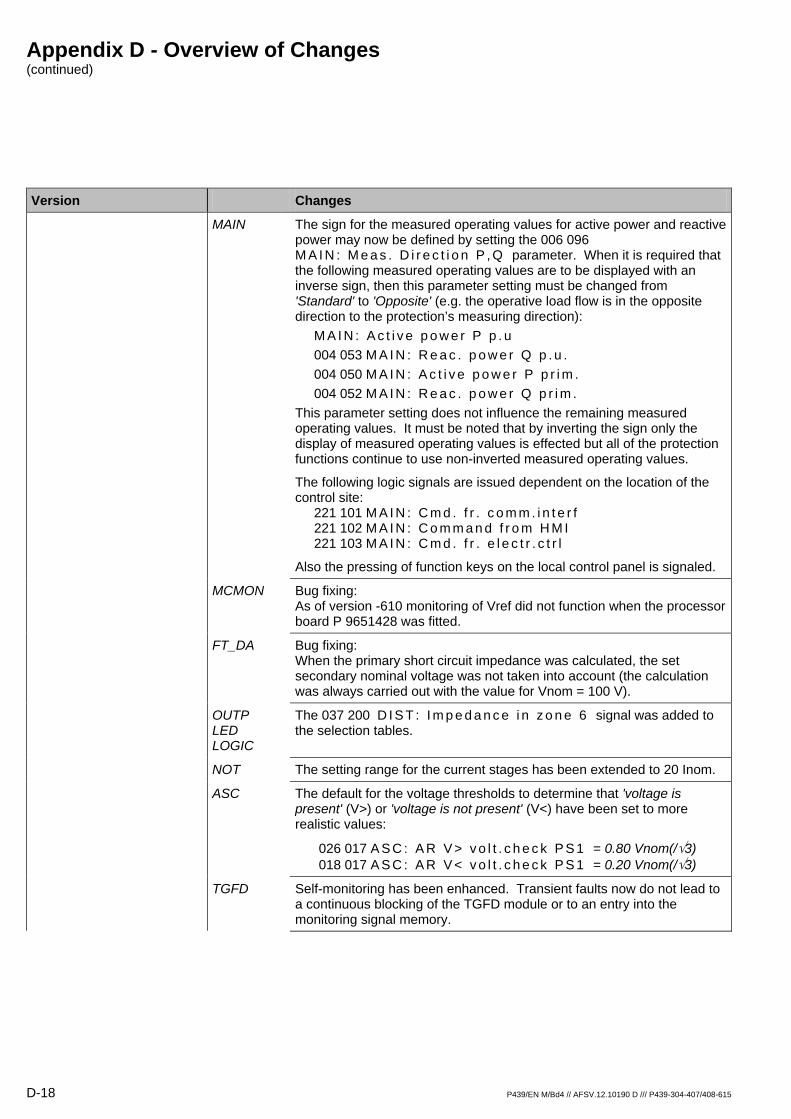
Appendix D - Overview of Changes (continued)
D-18 P439/EN M/Bd4 // AFSV.12.10190 D /// P439-304-407/408-615
Version Changes
MAIN The sign for the measured operating values for active power and reactive power may now be defined by setting the 006 096 M A I N : M e a s . D i r e c t i o n P , Q parameter. When it is required that the following measured operating values are to be displayed with an inverse sign, then this parameter setting must be changed from 'Standard' to 'Opposite' (e.g. the operative load flow is in the opposite direction to the protection’s measuring direction):
M A I N : A c t i v e p o w e r P p . u 004 053 M A I N : R e a c . p o w e r Q p . u . 004 050 M A I N : A c t i v e p o w e r P p r i m . 004 052 M A I N : R e a c . p o w e r Q p r i m .
This parameter setting does not influence the remaining measured operating values. It must be noted that by inverting the sign only the display of measured operating values is effected but all of the protection functions continue to use non-inverted measured operating values.
The following logic signals are issued dependent on the location of the control site: 221 101 M A I N : C m d . f r . c o m m . i n t e r f 221 102 M A I N : C o m m a n d f r o m H M I 221 103 M A I N : C m d . f r . e l e c t r . c t r l
Also the pressing of function keys on the local control panel is signaled.
MCMON Bug fixing: As of version -610 monitoring of Vref did not function when the processor board P 9651428 was fitted.
FT_DA Bug fixing: When the primary short circuit impedance was calculated, the set secondary nominal voltage was not taken into account (the calculation was always carried out with the value for Vnom = 100 V).
OUTP LED LOGIC
The 037 200 D I S T : I m p e d a n c e i n z o n e 6 signal was added to the selection tables.
NOT The setting range for the current stages has been extended to 20 Inom.
ASC The default for the voltage thresholds to determine that 'voltage is present' (V>) or 'voltage is not present' (V<) have been set to more realistic values:
026 017 A S C : A R V > v o l t . c h e c k P S 1 = 0.80 Vnom(/√3) 018 017 A S C : A R V < v o l t . c h e c k P S 1 = 0.20 Vnom(/√3)
TGFD Self-monitoring has been enhanced. Transient faults now do not lead to a continuous blocking of the TGFD module or to an entry into the monitoring signal memory.

Appendix D - Overview of Changes (continued)
P439/EN M/Bd4 // AFSV.12.10190 D /// P439-304-407/408-615 D-19
Version Changes
P<> Bug fixing: The setting parameters P<> were not converted when the settings for Inom or the dynamic range had been changed. A new calculation was only carried out after a warm restart.
Dependent on the setting (large operate value + large hysteresis) an overflow error could occur with the underpower stages P</<< and Q</<< so that the hysteresis could not be adhered to correctly.
LIMIT Additional stages have been implemented to monitor whether the reference voltage exceeds or falls below settable threshold values.
DEVxx The D E V x x : O p e n c m d . r e c e i v e d and D E V x x : C l o s e c m d . r e c e i v e d state signals are now issued and entered into the operating data memory.
The function type may now again be set in the range from 1 to 254. It must be observed that setting type numbers may not be applied from the range of standardized or reserved signals according to IEC 60870-5-103 for distance protection devices (80 to 8F hex = 128 to 143 dec) in order to avoid conflict situations with commands and signals within the protection’s extent.
The external device "3 position switches", created with the bay editor from the PC Access Software MiCOM S1, are now supported.
The setting parameters required only with communication protocols per IEC 60870-5 are now only available if such a protocol is used. The following settings are visible only when 003 215 C O M M 1 : B a s i c I E C 8 7 0 - 5 e n a b l has been set to 'Yes' (example shown for DEV01):
210 034 D E V 0 1 : F u n c t . t y p e , s i g n a l 210 035 D E V 0 1 : I n f o r m . N o . , s i g n a l 210 032 D E V 0 1 : F u n c t . t y p e , c o m m a n d 210 033 D E V 0 1 : I n f o r m . N o . , c o m m a n d 221 002 M A I N : S I a c t i v e U S E R 210 025 D E V 0 1 : O p e n w / o s t a t . i n t e r l 210 026 D E V 0 1 : C l o s e w / o s t a t . i n t . 210 039 D E V 0 1 : F c t . a s s i g . B I w S I o p e n 210 040 D E V 0 1 : F c t . a s s i g . B I w S I c l o s
P439-304-407/408-614-715 Hardware No changes
Release: 22.10.2007 Diagram No changes
Software
IEC Bug fixing:
Communication errors would occur if the output relay K200 was not wired correctly in bays with motor control.
After approximately 36.4 hours had passed measured operating values were no longer updated.
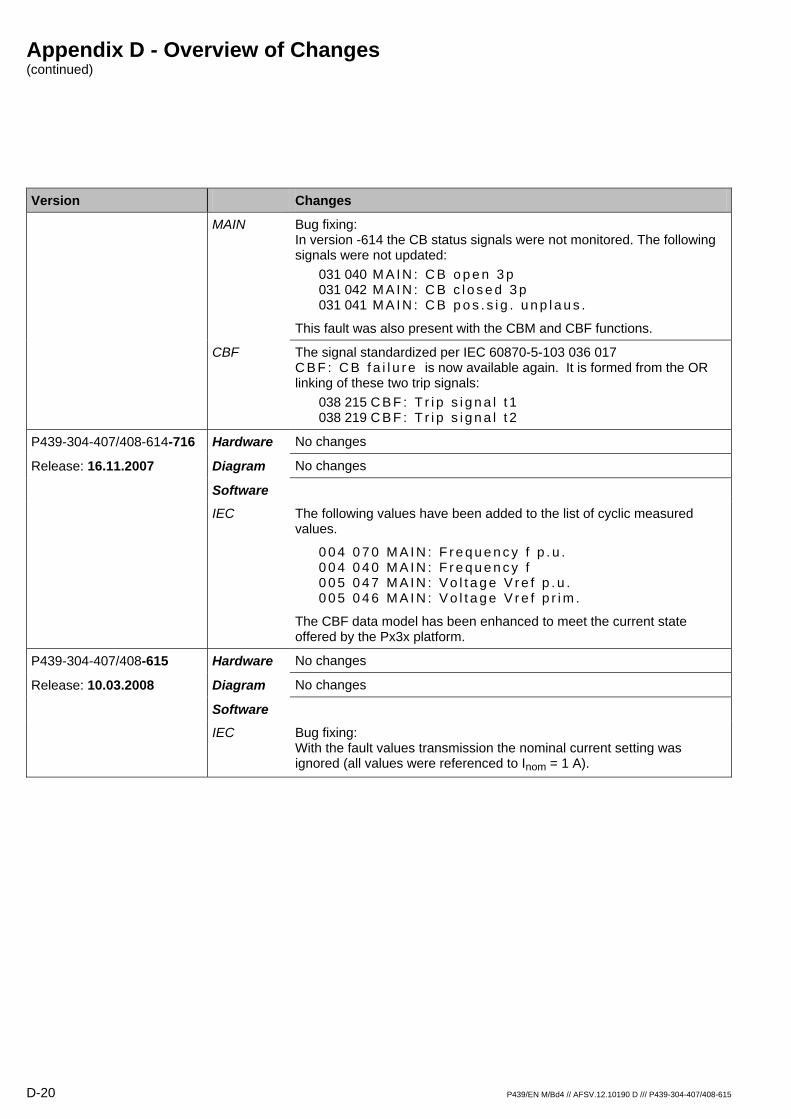
Appendix D - Overview of Changes (continued)
D-20 P439/EN M/Bd4 // AFSV.12.10190 D /// P439-304-407/408-615
Version Changes
MAIN Bug fixing: In version -614 the CB status signals were not monitored. The following signals were not updated:
031 040 M A I N : C B o p e n 3 p 031 042 M A I N : C B c l o s e d 3 p 031 041 M A I N : C B p o s . s i g . u n p l a u s .
This fault was also present with the CBM and CBF functions.
CBF The signal standardized per IEC 60870-5-103 036 017 C B F : C B f a i l u r e is now available again. It is formed from the OR linking of these two trip signals:
038 215 C B F : T r i p s i g n a l t 1 038 219 C B F : T r i p s i g n a l t 2
P439-304-407/408-614-716 Hardware No changes
Release: 16.11.2007 Diagram No changes
Software
IEC The following values have been added to the list of cyclic measured values.
0 0 4 0 7 0 M A I N : F r e q u e n c y f p . u . 0 0 4 0 4 0 M A I N : F r e q u e n c y f 0 0 5 0 4 7 M A I N : V o l t a g e V r e f p . u . 0 0 5 0 4 6 M A I N : V o l t a g e V r e f p r i m .
The CBF data model has been enhanced to meet the current state offered by the Px3x platform.
P439-304-407/408-615 Hardware No changes
Release: 10.03.2008 Diagram No changes
Software
IEC Bug fixing: With the fault values transmission the nominal current setting was ignored (all values were referenced to Inom = 1 A).


Schneider Electric 35 rue Joseph Monier 92506 Rueil-Malmaison FRANCE
Phone: +33 (0) 1 41 29 70 00 Fax: +33 (0) 1 41 29 71 00 www.schneider-electric.com Publishing: Schneider Electric
Publication: P439/EN M/Cd4 Version: -615 Vol.2 11/2010
© 2
010
Sch
neid
er E
lect
ric. A
ll rig
hts
rese
rved
.
MiCOM P439
Distance Protection and Control Unit
P439/EN AD/Ae4 (AFSV.12.10980 D)
Version P439 -304 -407/408 -615 ⇒ P439 -304 -407/408 -618
Upgrade Documentation


P439, Changes in software version -615 to -618
In the new versions of the Distance Protection and Control Unit MiCOM P439, several enhanced features and changes on existing features have been included. These are described with reference to the documentation listed below:
References Version Documentation Released
10.03.2008 P439-304-407/408-615 Technical Manual P439/EN M/Cd4 (AFSV.12.10190 D)
Note:
The software versions P439-61x constitute a product line that was developed independent to versions P439-63x. (The main difference is that the device versions with software versions P439-63x feature the “phase 2” implementation of function group IEC whereas software versions P439-61x continue with the “phase 1” implementation.)
P439/EN AD/Ae4 // AFSV.12.10980 D /// P439-304-407/408-618 3

P439, Changes in software version -615 to -618 (continued)
1 Overview
Changes Version
P439-304-407/408-616 Hardware No changes
Release: 26.03.2009 Diagram No changes
Software
LOC A new address was added to the hold-time of the measured value display. (031 072) L O C : H o l d - t . m e a s . v . d i s p l Values range from 1 to 60 seconds or 'Blocked'.
In the default setting the hold-time is 'Blocked', therefore the behavior is backwards-compatible (new functionality disabled).
Functionality: With the Bay Panel display the next or the previous configured measured value may be selected by pressing the keys "cursor down" or "cursor up". The new feature is that the next value will appear after the set time period has elapsed. When set to 'Blocked' the selected value will always be displayed.
Bug fixing:
The Password Display mode was not supported during a startup.
The detachable HMI did not support the character set 3.
COMM1 Communications protocol IEC 60870-5-103: When checking during test operations it is now possible to trigger signals (SIG) and contact positions (DEV) from the control part (previously only possible from the protection part).
Bug fixing:
Communications protocol DNP3: Contact positions were transmitted twice.
MODBUS protocol: The analog channel with the reference voltage value was not transmitted.
COMMx Bug fixing: The time-tags with entries into various recording memories could differ, in particular when the parameter subset was changed.
LED Modification of the default for the following parameter: (085 008) L E D : O p e r a t i n g m o d e H 4 - ES reset (fault)
MAIN The parameter (036 051) M A I N : C B c l o s e d s i g . E X T was renamed to: (036 051) M A I N : C B c l o s e d 3 p E X T
New addresses with a 32-bit measured value display have been added for the 4 energy measured values: (008 065) M A I N : A c t . e n e r g y o u t p . p r i m 0 ... 6,553,500.00 MWh (008 066) M A I N : A c t . e n e r g y i n p . p r i m 0 ... 6,553,500.00 MWh (008 067) M A I N : R e a c t . e n . o u t p . p r i m 0 ... 6,553,500.00 MVAr h (008 068) M A I N : R e a c t . e n . i n p . p r i m 0 ... 6,553,500.00 MVAr hBug fixing: The manual close command from the local control panel did not function.
4 P439/EN AD/Ae4 // AFSV.12.10980 D /// P439-304-407/408-618

P439, Changes in software version -615 to -618 (continued)
Changes Version
FT_DA The fault location may now be determined, based solely on a ground starting condition (without a general starting). For this the device determines all three phase-to-ground loop impedances and then provides the fault location based on the reactance of the measurement loop with the lowest impedance value. The following new data points have been introduced: (008 007, 008 008, 008 009, 008 027) F T _ D A : M o d e C a l c u l a t i o n P S x
Note: With version -630 this feature was again revised.
The signal (093 094) S F M O N : T G F D m o n . t r i g g e r e d is now no longer a fixed warning signal but it may be configured, if required, to (021 030) S F M O N : F c t . a s s i g n . W a r n i n g .
Bug fixing: The six signals (098 053) S F M O N : O u t p u t 3 0 to (098 058) S F M O N : O u t p u t 3 2 ( t ) did not issue a warning signal when they had been configured to (021 030) S F M O N : F c t . a s s i g n . W a r n i n g .
SFMON
MCMON During a starting of the backup overcurrent-time protection (BUOC) monitoring of the negative-sequence voltage is now suspended. This will prevent the measuring-circuit monitoring function from dropping out and distance protection from becoming active again when the measured value falls below the threshold Vneg> because of a short-circuit occurring in the primary system.
DIST Monitoring speed and accuracy of the tripping time with isolated and compensated systems has been improved.
The designation text at (035 073) D I S T : T r i p s i g . Z o n e 2 - 6 was corrected to: (035 073) D I S T : T r i p s i g . Z o n e 2 - 8
The following parameters have been given new default values: D I S T : Z f w , P G P S x – 0 Ω D I S T : Z f w , P P P S x – 0 Ω DIST: kze,PG HSR PSx – 1.50 DIST: kze,PP HSR PSx – 1.50 DIST: kze,PG TDR PSx – 1.50 DIST: kze,PP TDR PSx – 1.50
PSIG The following parameter has a new default value: P S I G : E c h o o n r e c e i v e P S x – Without
The operative time 2 (A R C : O p e r a t i v e t i m e 2 P S x ) is now available. In relation with the now also available maximum dead time at A R C : D e a d t i m e m a x P S x , it will now be possible to set a dead time according to ASC requirements which will prevent predictable unsuccessful reclosure commands.
Bug fixing: Up to now the zone extension factors (kze) from the high-speed reclosure (HSR) were always used, even with a time-delayed reclosure (TDR).
ARC
ASC When the operating mode is set to 'Vref & Z1 but not V', the significance of 'Z1' has been modified such that the condition is met with a Trip by distance zone 1 OR a PSIG Trip. This condition now makes a reclosure possible if the primary fault has occurred on the protected line.
P439/EN AD/Ae4 // AFSV.12.10980 D /// P439-304-407/408-618 5
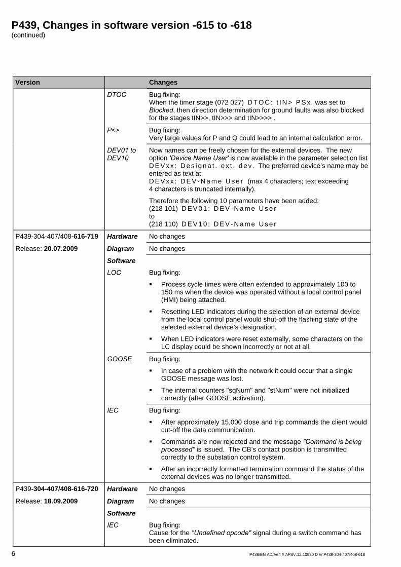
P439, Changes in software version -615 to -618 (continued)
Changes Version
DTOC Bug fixing: When the timer stage (072 027) D T O C : t I N > P S x was set to Blocked, then direction determination for ground faults was also blocked for the stages tIN>>, tIN>>> and tIN>>>> .
P<> Bug fixing: Very large values for P and Q could lead to an internal calculation error.
Now names can be freely chosen for the external devices. The new option 'Device Name User' is now available in the parameter selection list D E V x x : D e s i g n a t . e x t . d e v . The preferred device’s name may be entered as text at D E V x x : D E V - N a m e U s e r (max 4 characters; text exceeding 4 characters is truncated internally).
Therefore the following 10 parameters have been added: (218 101) D E V 0 1 : D E V - N a m e U s e r to (218 110) D E V 1 0 : D E V - N a m e U s e r
DEV01 to DEV10
P439-304-407/408-616-719 Hardware No changes
Release: 20.07.2009 Diagram No changes
Software
LOC Bug fixing:
Process cycle times were often extended to approximately 100 to 150 ms when the device was operated without a local control panel (HMI) being attached.
Resetting LED indicators during the selection of an external device from the local control panel would shut-off the flashing state of the selected external device’s designation.
When LED indicators were reset externally, some characters on the LC display could be shown incorrectly or not at all.
GOOSE Bug fixing:
In case of a problem with the network it could occur that a single GOOSE message was lost.
The internal counters "sqNum" and "stNum" were not initialized correctly (after GOOSE activation).
IEC Bug fixing:
After approximately 15,000 close and trip commands the client would cut-off the data communication.
Commands are now rejected and the message "Command is being processed" is issued. The CB’s contact position is transmitted correctly to the substation control system.
After an incorrectly formatted termination command the status of the external devices was no longer transmitted.
P439-304-407/408-616-720 Hardware No changes
Release: 18.09.2009 Diagram No changes
Software
IEC Bug fixing: Cause for the "Undefined opcode" signal during a switch command has been eliminated.
6 P439/EN AD/Ae4 // AFSV.12.10980 D /// P439-304-407/408-618
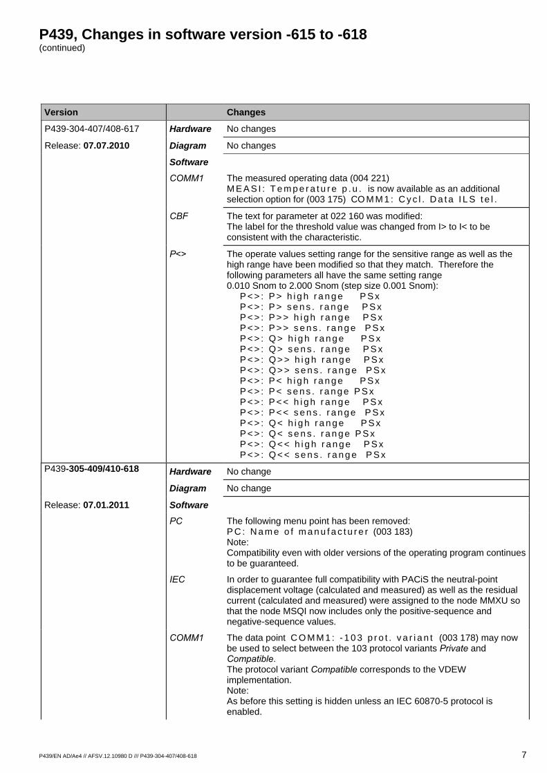
P439, Changes in software version -615 to -618 (continued)
Changes Version
P439-304-407/408-617 Hardware No changes
Release: 07.07.2010 Diagram No changes
Software
COMM1 The measured operating data (004 221) M E A S I : T e m p e r a t u r e p . u . is now available as an additional selection option for (003 175) CO M M 1 : C y c l . D a t a I L S t e l .
CBF The text for parameter at 022 160 was modified: The label for the threshold value was changed from I> to I< to be consistent with the characteristic.
The operate values setting range for the sensitive range as well as the high range have been modified so that they match. Therefore the following parameters all have the same setting range 0.010 Snom to 2.000 Snom (step size 0.001 Snom): P < > : P > h i g h r a n g e P S x P < > : P > s e n s . r a n g e P S x P < > : P > > h i g h r a n g e P S x P < > : P > > s e n s . r a n g e P S x P < > : Q > h i g h r a n g e P S x P < > : Q > s e n s . r a n g e P S x P < > : Q > > h i g h r a n g e P S x P < > : Q > > s e n s . r a n g e P S x P < > : P < h i g h r a n g e P S x P < > : P < s e n s . r a n g e P S x P < > : P < < h i g h r a n g e P S x P < > : P < < s e n s . r a n g e P S x P < > : Q < h i g h r a n g e P S x P < > : Q < s e n s . r a n g e P S x P < > : Q < < h i g h r a n g e P S x P < > : Q < < s e n s . r a n g e P S x
P<>
Hardware No change P439-305-409/410-618
No change Diagram
Release: 07.01.2011 Software The following menu point has been removed:
P C : N a m e o f m a n u f a c t u r e r (003 183) Note: Compatibility even with older versions of the operating program continues to be guaranteed.
PC
In order to guarantee full compatibility with PACiS the neutral-point displacement voltage (calculated and measured) as well as the residual current (calculated and measured) were assigned to the node MMXU so that the node MSQI now includes only the positive-sequence and negative-sequence values.
IEC
The data point C O M M 1 : - 1 0 3 p r o t . v a r i a n t (003 178) may now be used to select between the 103 protocol variants Private and Compatible. The protocol variant Compatible corresponds to the VDEW implementation. Note: As before this setting is hidden unless an IEC 60870-5 protocol is enabled.
COMM1
P439/EN AD/Ae4 // AFSV.12.10980 D /// P439-304-407/408-618 7
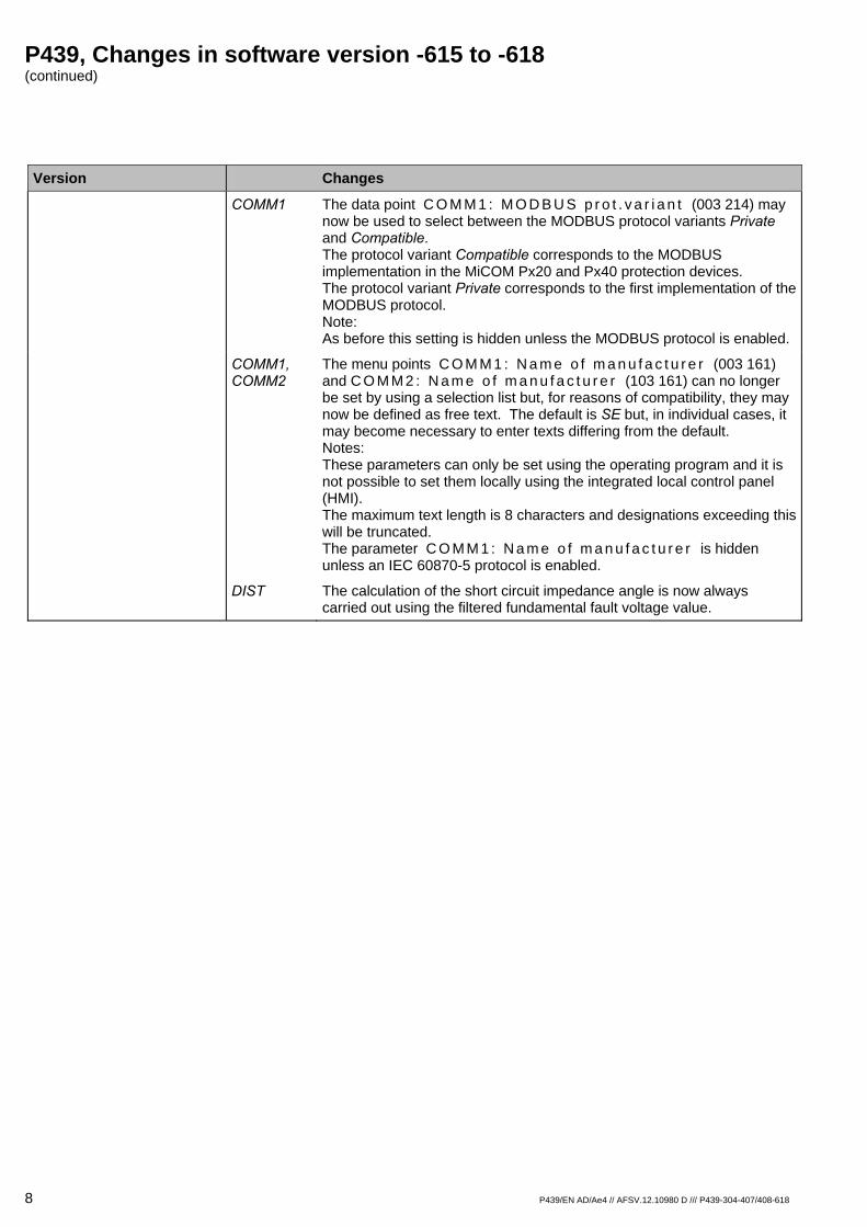
P439, Changes in software version -615 to -618 (continued)
8 P439/EN AD/Ae4 // AFSV.12.10980 D /// P439-304-407/408-618
Version Changes COMM1 The data point C O M M 1 : M O D B U S p r o t . v a r i a n t (003 214) may
now be used to select between the MODBUS protocol variants Private and Compatible. The protocol variant Compatible corresponds to the MODBUS implementation in the MiCOM Px20 and Px40 protection devices. The protocol variant Private corresponds to the first implementation of the MODBUS protocol. Note: As before this setting is hidden unless the MODBUS protocol is enabled.
COMM1, COMM2
The menu points C O M M 1 : N a m e o f m a n u f a c t u r e r (003 161) and C O M M 2 : N a m e o f m a n u f a c t u r e r (103 161) can no longer be set by using a selection list but, for reasons of compatibility, they may now be defined as free text. The default is SE but, in individual cases, it may become necessary to enter texts differing from the default. Notes: These parameters can only be set using the operating program and it is not possible to set them locally using the integrated local control panel (HMI). The maximum text length is 8 characters and designations exceeding this will be truncated. The parameter C O M M 1 : N a m e o f m a n u f a c t u r e r is hidden unless an IEC 60870-5 protocol is enabled.
DIST The calculation of the short circuit impedance angle is now always carried out using the filtered fundamental fault voltage value.

Customer Care Centre
http://www.schneider-electric.com/CCC
© 2
011
Sch
neid
er E
lect
ric. A
ll rig
hts
rese
rved
.
Schneider Electric 35 rue Joseph Monier 92506 Rueil-Malmaison FRANCE
Phone: +33 (0) 1 41 29 70 00 Fax: +33 (0) 1 41 29 71 00 www.schneider-electric.com Publishing: Schneider ElectricPublication: P439/EN AD/Ae4 // AFSV.12.10980 D /// P439-304-407/408-618 06/2011
MiCOM P439
Distance Protection and Control Unit
P439/EN AD/Ck5 (AFSV.12.10372 D)
Version P439 -304 -407/408 -615 ⇒ P439 -305 -409/410 -630
Upgrade Documentation

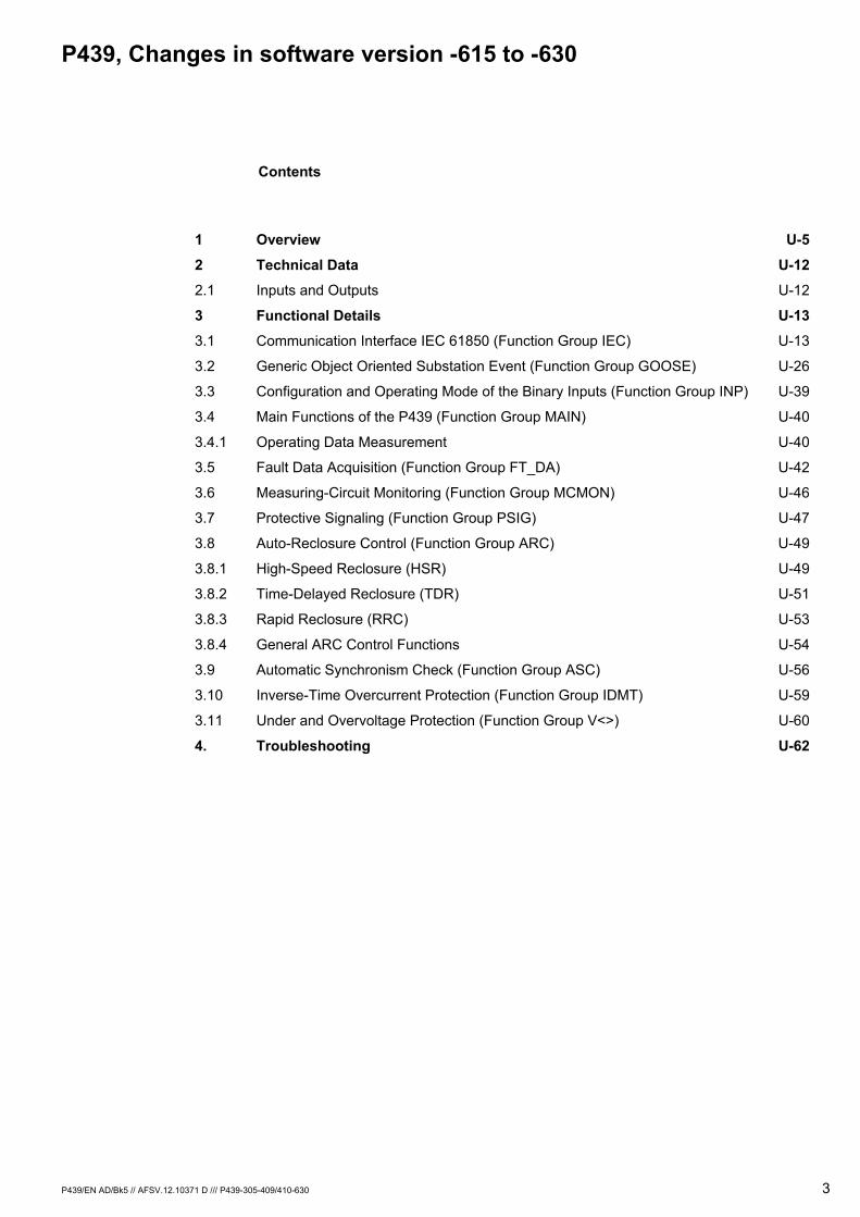
P439, Changes in software version -615 to -630
P439/EN AD/Bk5 // AFSV.12.10371 D /// P439-305-409/410-630 3
Contents
1 Overview U-5
2 Technical Data U-12
2.1 Inputs and Outputs U-12
3 Functional Details U-13
3.1 Communication Interface IEC 61850 (Function Group IEC) U-13
3.2 Generic Object Oriented Substation Event (Function Group GOOSE) U-26
3.3 Configuration and Operating Mode of the Binary Inputs (Function Group INP) U-39
3.4 Main Functions of the P439 (Function Group MAIN) U-40
3.4.1 Operating Data Measurement U-40
3.5 Fault Data Acquisition (Function Group FT_DA) U-42
3.6 Measuring-Circuit Monitoring (Function Group MCMON) U-46
3.7 Protective Signaling (Function Group PSIG) U-47
3.8 Auto-Reclosure Control (Function Group ARC) U-49
3.8.1 High-Speed Reclosure (HSR) U-49
3.8.2 Time-Delayed Reclosure (TDR) U-51
3.8.3 Rapid Reclosure (RRC) U-53
3.8.4 General ARC Control Functions U-54
3.9 Automatic Synchronism Check (Function Group ASC) U-56
3.10 Inverse-Time Overcurrent Protection (Function Group IDMT) U-59
3.11 Under and Overvoltage Protection (Function Group V<>) U-60
4. Troubleshooting U-62
P439, Changes in software version -615 to -630 (continued)
4 P439/EN AD/Bk5 // AFSV.12.10371 D /// P439-305-409/410-630
In the new version of the P439 several enhanced features and changes on existing features have been included. These are described with references to the Technical Manual listed below.
References Released Version Documentation
10.03.2008 P439-304-407/408-615 Technical Manual P439/EN M//Cd4 (AFSV.12.10190 D)
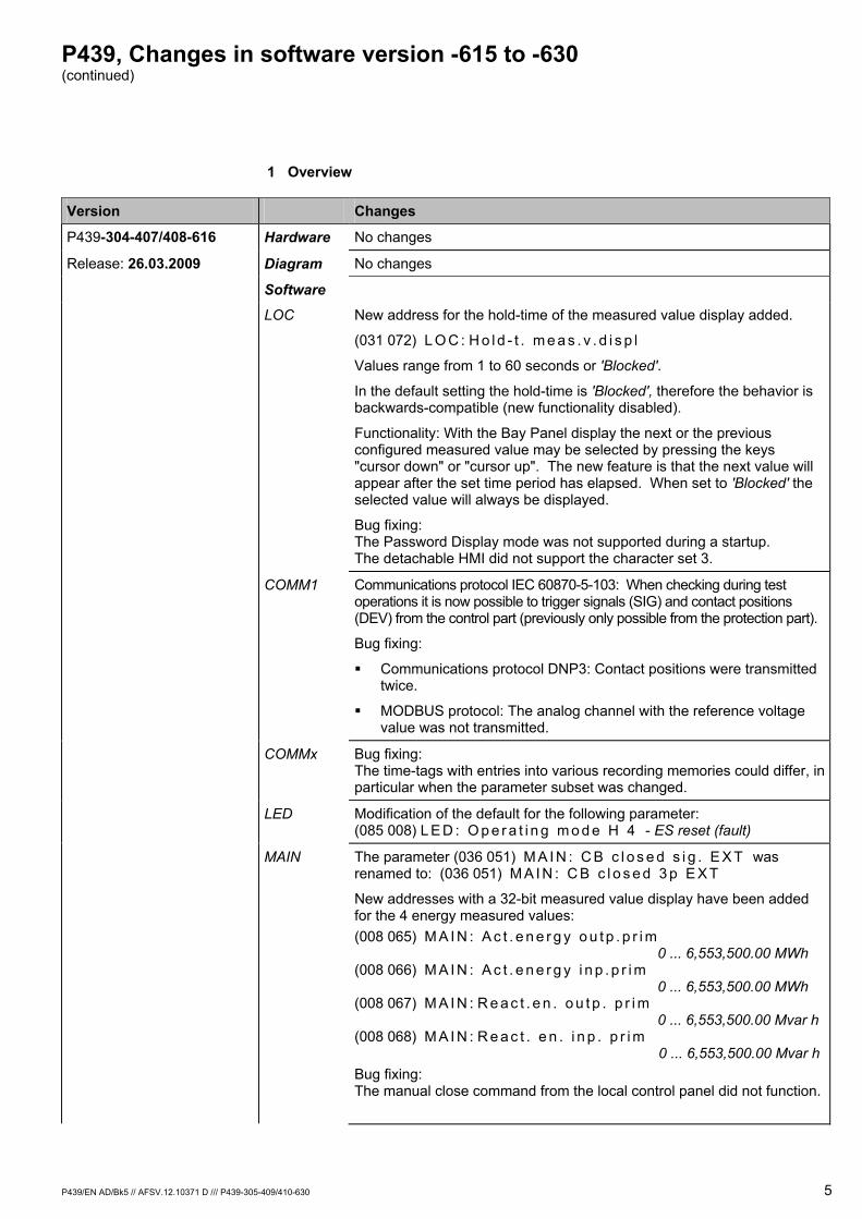
P439, Changes in software version -615 to -630 (continued)
P439/EN AD/Bk5 // AFSV.12.10371 D /// P439-305-409/410-630 5
1 Overview
Version Changes
P439-304-407/408-616 Hardware No changes
Release: 26.03.2009 Diagram No changes
Software
LOC New address for the hold-time of the measured value display added.
(031 072) L O C : H o l d - t . m e a s . v . d i s p l
Values range from 1 to 60 seconds or 'Blocked'.
In the default setting the hold-time is 'Blocked', therefore the behavior is backwards-compatible (new functionality disabled).
Functionality: With the Bay Panel display the next or the previous configured measured value may be selected by pressing the keys "cursor down" or "cursor up". The new feature is that the next value will appear after the set time period has elapsed. When set to 'Blocked' the selected value will always be displayed.
Bug fixing: The Password Display mode was not supported during a startup. The detachable HMI did not support the character set 3.
COMM1 Communications protocol IEC 60870-5-103: When checking during test operations it is now possible to trigger signals (SIG) and contact positions (DEV) from the control part (previously only possible from the protection part).
Bug fixing:
Communications protocol DNP3: Contact positions were transmitted twice.
MODBUS protocol: The analog channel with the reference voltage value was not transmitted.
COMMx Bug fixing: The time-tags with entries into various recording memories could differ, in particular when the parameter subset was changed.
LED Modification of the default for the following parameter: (085 008) L E D : O p e r a t i n g m o d e H 4 - ES reset (fault)
MAIN The parameter (036 051) M A I N : C B c l o s e d s i g . E X T was renamed to: (036 051) M A I N : C B c l o s e d 3 p E X T
New addresses with a 32-bit measured value display have been added for the 4 energy measured values: (008 065) M A I N : A c t . e n e r g y o u t p . p r i m 0 ... 6,553,500.00 MWh (008 066) M A I N : A c t . e n e r g y i n p . p r i m 0 ... 6,553,500.00 MWh (008 067) M A I N : R e a c t . e n . o u t p . p r i m 0 ... 6,553,500.00 Mvar h (008 068) M A I N : R e a c t . e n . i n p . p r i m 0 ... 6,553,500.00 Mvar h Bug fixing: The manual close command from the local control panel did not function.

P439, Changes in software version -615 to -630 (continued)
6 P439/EN AD/Bk5 // AFSV.12.10371 D /// P439-305-409/410-630
Version Changes
FT_DA The fault location may now be determined, based solely on a ground starting condition (without a general start). For this the device determines all three phase-to-ground loop impedances and then provides the fault location based on the reactance of the measurement loop with the lowest impedance value. The following new data points have been introduced: (008 007, 008 008, 008 009, 008 027) F T _ D A : M o d e C a l c u l a t i o n P S x
Note: With the present version P439 -630 this feature was again revised.
SFMON The signal (093 094) S F M O N : T G F D m o n . t r i g g e r e d is now no longer a fixed warning signal but it may be configured, if required, to (021 030) S F M O N : F c t . a s s i g n . W a r n i n g .
Bug fixing: The signals (098 053) S F M O N : O u t p u t 3 0 to (098 058) S F M O N : O u t p u t 3 2 ( t ) did not issue a warning signal if they had been configured to (021 030) S F M O N : F c t . a s s i g n . W a r n i n g .
MCMON During a starting of the backup overcurrent-time protection (BUOC) monitoring of the negative-sequence voltage is now suspended. This will prevent the measuring-circuit monitoring function from dropping out and distance protection from becoming active again when the measured value falls below the threshold Vneg> because of a short-circuit occurring in the primary system.
DIST Monitoring speed and accuracy of the tripping time with isolated and compensated systems has been improved.
The designation text at (035 073) D I S T : T r i p s i g . Z o n e 2 - 6 was corrected to: (035 073) D I S T : T r i p s i g . Z o n e 2 - 8
The following parameters have been given new default values: D I S T : Z f w , P G P S x – 0 Ω D I S T : Z f w , P P P S x – 0 Ω DIST: kze,PG HSR PSx – 1.50 DIST: kze,PP HSR PSx – 1.50 DIST: kze,PG TDR PSx – 1.50 DIST: kze,PP TDR PSx – 1.50
PSIG This parameter has been given a new default value: P S I G : E c h o o n r e c e i v e P S x - Without
ARC The operative time 2 (A R C : O p e r a t i v e t i m e 2 P S x ) is now available.
Bug fixing: Up to now the zone extension factors (kze) from the high-speed reclosure (HSR) were always used, even with a time-delayed reclosure (TDR).
ASC When the operating mode is set to 'Vref & Z1 but not V,' the meaning of 'Z1' has been modified such that the condition is met with a Trip by distance zone 1 OR a PSIG Trip. This measure now makes a reclosure possible if the primary fault has occurred on the protected line.
DTOC Bug fixing: When the timer stage (072 027) D T O C : t I N > P S x was set to 'Blocked', then direction determination for ground faults was also blocked for the stages tIN>>, tIN>>> and tIN>>>> .
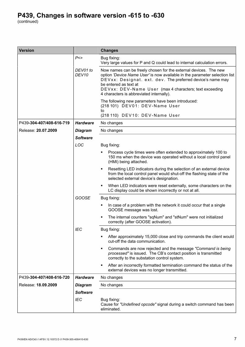
P439, Changes in software version -615 to -630 (continued)
P439/EN AD/Ck5 // AFSV.12.10372 D /// P439-305-409/410-630 7
Version Changes
P<> Bug fixing: Very large values for P and Q could lead to internal calculation errors.
DEV01 to DEV10
Now names can be freely chosen for the external devices. The new option 'Device Name User' is now available in the parameter selection list D E V x x : D e s i g n a t . e x t . d e v . The preferred device’s name may be entered as text at D E V x x : D E V - N a m e U s e r (max 4 characters; text exceeding 4 characters is abbreviated internally).
The following new parameters have been introduced: (218 101) D E V 0 1 : D E V - N a m e U s e r to (218 110) D E V 1 0 : D E V - N a m e U s e r
P439-304-407/408-616-719 Hardware No changes
Release: 20.07.2009 Diagram No changes
Software
LOC Bug fixing:
Process cycle times were often extended to approximately 100 to 150 ms when the device was operated without a local control panel (HMI) being attached.
Resetting LED indicators during the selection of an external device from the local control panel would shut-off the flashing state of the selected external device’s designation.
When LED indicators were reset externally, some characters on the LC display could be shown incorrectly or not at all.
GOOSE Bug fixing:
In case of a problem with the network it could occur that a single GOOSE message was lost.
The internal counters "sqNum" and "stNum" were not initialized correctly (after GOOSE activation).
IEC Bug fixing:
After approximately 15,000 close and trip commands the client would cut-off the data communication.
Commands are now rejected and the message "Command is being processed" is issued. The CB’s contact position is transmitted correctly to the substation control system.
After an incorrectly formatted termination command the status of the external devices was no longer transmitted.
P439-304-407/408-616-720 Hardware No changes
Release: 18.09.2009 Diagram No changes
Software
IEC Bug fixing: Cause for "Undefined opcode" signal during a switch command has been eliminated.
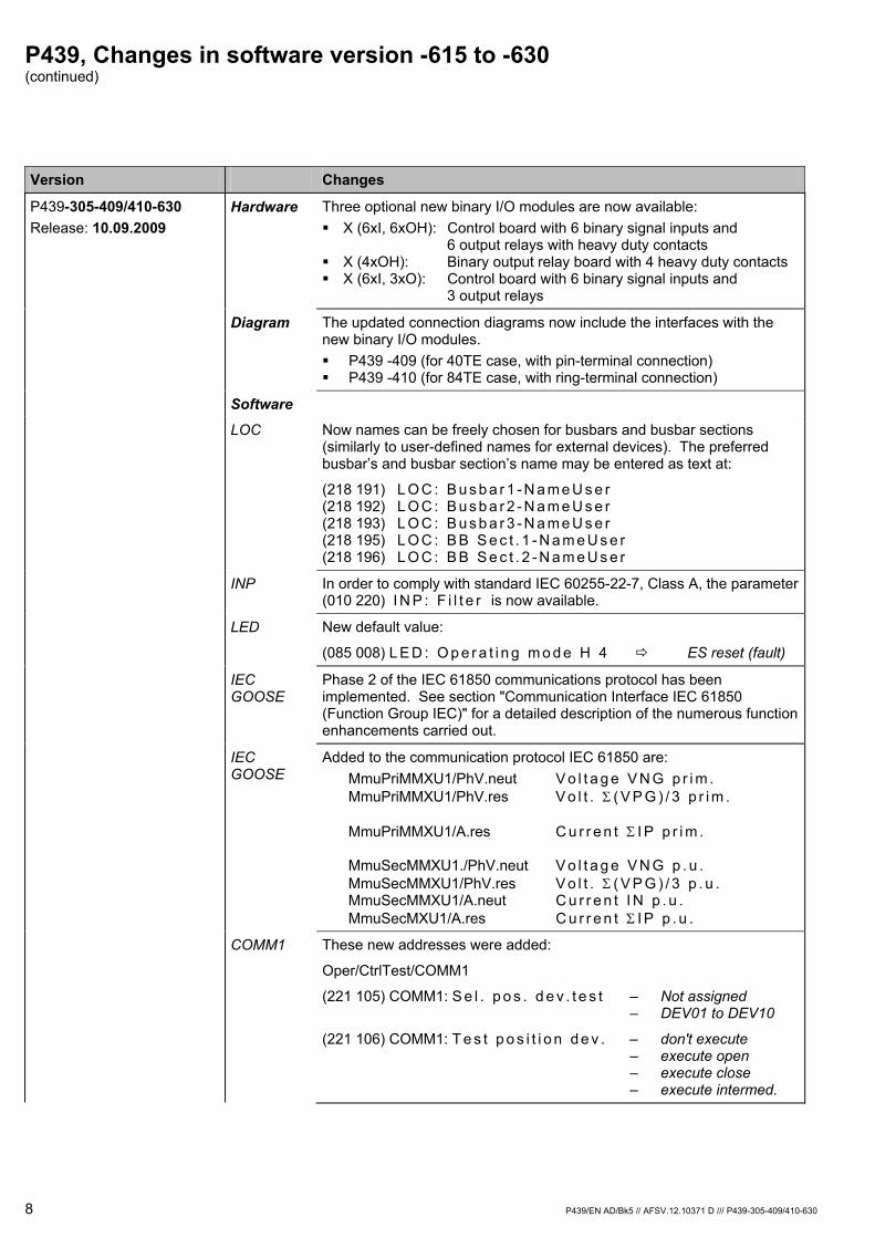
P439, Changes in software version -615 to -630 (continued)
8 P439/EN AD/Bk5 // AFSV.12.10371 D /// P439-305-409/410-630
Version Changes
P439-305-409/410-630 Release: 10.09.2009
Hardware Three optional new binary I/O modules are now available: X (6xI, 6xOH): Control board with 6 binary signal inputs and
6 output relays with heavy duty contacts X (4xOH): Binary output relay board with 4 heavy duty contacts X (6xI, 3xO): Control board with 6 binary signal inputs and
3 output relays
Diagram The updated connection diagrams now include the interfaces with the new binary I/O modules. P439 -409 (for 40TE case, with pin-terminal connection) P439 -410 (for 84TE case, with ring-terminal connection)
Software LOC Now names can be freely chosen for busbars and busbar sections
(similarly to user-defined names for external devices). The preferred busbar’s and busbar section’s name may be entered as text at:
(218 191) L O C : B u s b a r 1 - N a m e U s e r (218 192) L O C : B u s b a r 2 - N a m e U s e r (218 193) L O C : B u s b a r 3 - N a m e U s e r (218 195) L O C : B B S e c t . 1 - N a m e U s e r (218 196) L O C : B B S e c t . 2 - N a m e U s e r
INP In order to comply with standard IEC 60255-22-7, Class A, the parameter (010 220) I N P : F i l t e r is now available.
LED New default value:
(085 008) L E D : O p e r a t i n g m o d e H 4 ES reset (fault)
IEC GOOSE
Phase 2 of the IEC 61850 communications protocol has been implemented. See section "Communication Interface IEC 61850 (Function Group IEC)" for a detailed description of the numerous function enhancements carried out.
IEC GOOSE
Added to the communication protocol IEC 61850 are: MmuPriMMXU1/PhV.neut V o l t a g e V N G p r i m . MmuPriMMXU1/PhV.res V o l t . Σ ( V P G ) / 3 p r i m . MmuPriMMXU1/A.res C u r r e n t Σ I P p r i m . MmuSecMMXU1./PhV.neut V o l t a g e V N G p . u . MmuSecMMXU1/PhV.res V o l t . Σ ( V P G ) / 3 p . u . MmuSecMMXU1/A.neut C u r r e n t I N p . u . MmuSecMXU1/A.res C u r r e n t Σ I P p . u .
COMM1 These new addresses were added:
Oper/CtrlTest/COMM1
(221 105) COMM1: S e l . p o s . d e v . t e s t – Not assigned – DEV01 to DEV10
(221 106) COMM1: T e s t p o s i t i o n d e v . – don't execute – execute open – execute close – execute intermed.
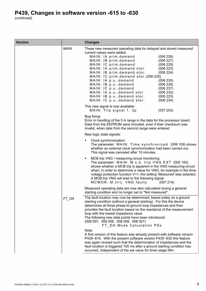
P439, Changes in software version -615 to -630 (continued)
P439/EN AD/Bk5 // AFSV.12.10371 D /// P439-305-409/410-630 9
Version Changes
MAIN These new measured operating data for delayed and stored measured
current values were added: M A I N : I A p r i m , d e m a n d (006 226) M A I N : I B p r i m , d e m a n d (006 227) M A I N : I C p r i m , d e m a n d (006 228) M A I N : I A p r i m , d e m a n d s t o r . (006 223) M A I N : I B p r i m , d e m a n d s t o r . (006 224) M A I N : I C p r i m , d e m a n d s t o r . (006 225) M A I N : I A p . u . , d e m a n d (006 235) M A I N : I B p . u . , d e m a n d (006 236) M A I N : I C p . u . , d e m a n d (006 237) M A I N : I A p . u . , d e m a n d s t o r . (006 232) M A I N : I B p . u . , d e m a n d s t o r . (006 223) M A I N : I C p . u . , d e m a n d s t o r . (006 234)
This new signal is now available: M A I N : T r i p s i g n a l 1 , 3 p (037 253)
Bug fixing: Error in handling of the 5 A range in the data for the processor board. Data from the EEPROM were included, even if their checksum was invalid, when data from the second range were entered.
New logic state signals:
Clock synchronization: The parameter: M A I N : T i m e s y n c h r o n i z e d (009 109) shows whether an external clock synchronization had been carried out. This signal was canceled after 10 minutes.
MCB trip VNG / measuring-circuit monitoring: The parameter: M A I N : M . c . b . t r i p V N G E X T (002 183) shows whether a MCB trip is apparent in the VNG measuring-circuit when, in order to determine a value for VNG, for example in the time-voltage protection function V<>, the setting 'Measured' was selected. A MCB trip VNG will lead to the following signal: M C M O N : M . c i r c . V N G f a u l t y (007 214)
Measured operating data are now also calculated during a general starting condition and no longer set to "Not measured".
FT_DA The fault location may now be determined, based solely on a ground starting condition (without a general starting). For this the device determines all three phase-to-ground loop impedances and then provides the fault location based on the reactance of the measurement loop with the lowest impedance value. The following new data points have been introduced: (008 007, 008 008, 008 009, 008 027) F T _ D A : M o d e C a l c u l a t i o n P S x Note: A first version of this feature was already present with software version P439 -616. With the present software version P439 -630 this feature was again revised such that the determination of impedances and the fault location is triggered 100 ms after a ground starting condition has occurred, independent of the set value for timer stage tIN>.
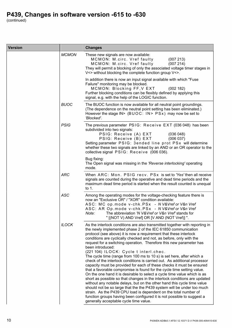
P439, Changes in software version -615 to -630 (continued)
10 P439/EN AD/Bk5 // AFSV.12.10371 D /// P439-305-409/410-630
Version Changes MCMON These new signals are now available:
M C M O N : M . c i r c . V r e f f a u l t y (007 213) M C M O N : M . c i r c . V r e f f a u l t y (007 214) They will permit a blocking of only the associated voltage timer stages in V<> without blocking the complete function group V<>.
In addition there is now an input signal available with which "Fuse Failure" monitoring may be blocked. M C M O N : B l o c k i n g F F , V E X T (002 182) Further blocking conditions can be flexibly defined by applying this signal, e.g. with the help of the LOGIC function.
BUOC The BUOC function is now available for all neutral point groundings. (The dependence on the neutral point setting has been eliminated.) However the stage IN> (B U O C : I N > P S x ) may now be set to 'Blocked'.
PSIG The previous parameter PS I G : R e c e i v e E X T (036 048) has been subdivided into two signals: P S I G : R e c e i v e ( A ) E X T (036 048) P S I G : R e c e i v e ( B ) E X T (006 037) Setting parameter P S I G : 3 e n d e d l i n e p r o t P S x will determine whether these two signals are linked by an AND or an OR operator to the collective signal P S I G : R e c e i v e (006 036).
Bug fixing: The Open signal was missing in the 'Reverse interlocking' operating mode.
ARC When A R C : M o n . P S I G r e c v . P S x is set to 'Yes' then all receive signals are counted during the operative and dead time periods and the maximum dead time period is started when the result counted is unequal to 1.
ASC Among the operating modes for the voltage-checking feature there is now an "Exclusive OR" / "XOR" condition available: A S C : M C o p . m o d e v - c h k . P S x - N V&Vref or V&n Vref A S C : A R O p . m o d e v - c h k . P S x - N V&Vref or V&n Vref Note: The abbreviation 'N V&Vref or V&n Vref' stands for " [(NOT V) AND Vref] OR [V AND (NOT Vref)] ".
ILOCK As the interlock conditions are also transmitted together with reporting in the newly implemented phase 2 of the IEC 61850 communication protocol (see above) it is now a requirement that these interlock conditions are cyclically checked and not, as before, only with the request for a switching operation. Therefore this new parameter has been introduced: (221 104) I L O C K : C y c l e t i n t e r l . c h e c . The cycle time (range from 100 ms to 10 s) is set here, after which a check of the interlock conditions is carried out. As additional processor capacity must be provided for each of these checks it must be ensured that a favorable compromise is found for the cycle time setting value. On the one hand it is desirable to select a cycle time value which is as short as possible so that changes in the interlock conditions are updated without any notable delays, but on the other hand this cycle time value should not be so large that the the P439 system will be under too much strain. As the P439 CPU load is dependent on the total number of function groups having been configured it is not possible to suggest a generally acceptable cycle time value.
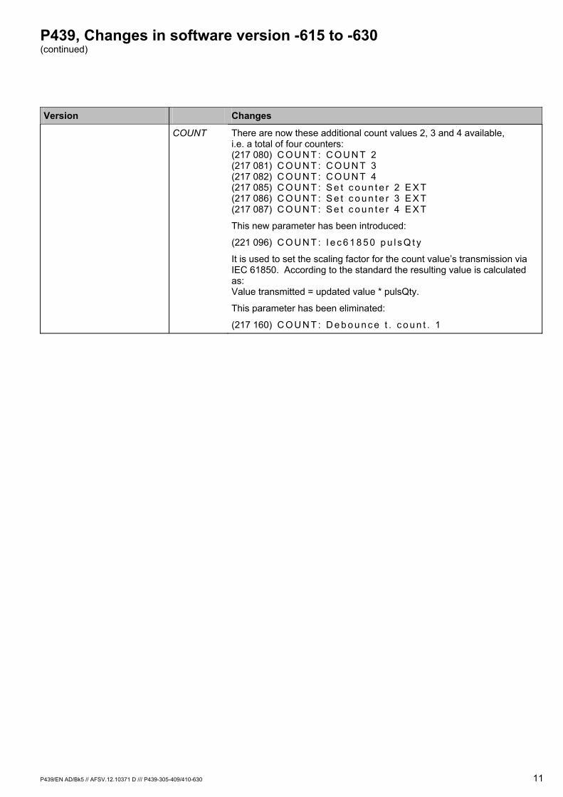
P439, Changes in software version -615 to -630 (continued)
P439/EN AD/Bk5 // AFSV.12.10371 D /// P439-305-409/410-630 11
Version Changes
COUNT There are now these additional count values 2, 3 and 4 available, i.e. a total of four counters: (217 080) C O U N T : C O U N T 2 (217 081) C O U N T : C O U N T 3 (217 082) C O U N T : C O U N T 4 (217 085) C O U N T : S e t c o u n t e r 2 E X T (217 086) C O U N T : S e t c o u n t e r 3 E X T (217 087) C O U N T : S e t c o u n t e r 4 E X T
This new parameter has been introduced:
(221 096) C O U N T : I e c 6 1 8 5 0 p u l s Q t y
It is used to set the scaling factor for the count value’s transmission via IEC 61850. According to the standard the resulting value is calculated as: Value transmitted = updated value * pulsQty.
This parameter has been eliminated:
(217 160) C O U N T : D e b o u n c e t . c o u n t . 1
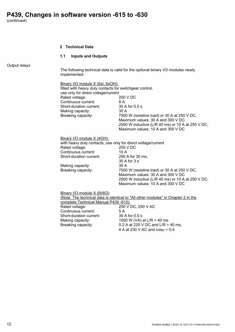
P439, Changes in software version -615 to -630 (continued)
12 P439/EN AD/Bk5 // AFSV.12.10371 D /// P439-305-409/410-630
2 Technical Data
1.1 Inputs and Outputs
Output relays The following technical data is valid for the optional binary I/O modules newly implemented:
Binary I/O module X (6xI, 6xOH): fitted with heavy duty contacts for switchgear control, use only for direct voltage/current Rated voltage: 250 V DC Continuous current: 8 A Short-duration current: 30 A for 0.5 s Making capacity: 30 A Breaking capacity: 7500 W (resistive load) or 30 A at 250 V DC, Maximum values: 30 A and 300 V DC 2500 W inductive (L/R 40 ms) or 10 A at 250 V DC, Maximum values: 10 A and 300 V DC
Binary I/O module X (4OH): with heavy duty contacts, use only for direct voltage/current Rated voltage: 250 V DC Continuous current: 10 A Short-duration current: 250 A for 30 ms, 30 A for 3 s Making capacity: 30 A Breaking capacity: 7500 W (resistive load) or 30 A at 250 V DC, Maximum values: 30 A and 300 V DC 2500 W inductive (L/R 40 ms) or 10 A at 250 V DC, Maximum values: 10 A and 300 V DC
Binary I/O module X (6I/6O) (Note: The technical data is identical to "All other modules" in Chapter 2 in the complete Technical Manual P439 -615): Rated voltage: 250 V DC, 250 V AC Continuous current: 5 A Short-duration current: 30 A for 0.5 s Making capacity: 1000 W (VA) at L/R = 40 ms Breaking capacity: 0.2 A at 220 V DC and L/R = 40 ms, 4 A at 230 V AC and cosϕ = 0.4
P439, Changes in software version -615 to -630 (continued)
P439/EN AD/Bk5 // AFSV.12.10371 D /// P439-305-409/410-630 13
2 Functional Details
2.1 Communication Interface IEC 61850 (Function Group IEC)
As a further option the device is provided with the interface protocol according to the Ethernet based communication standard IEC 61850. As of firmware version P439 -630 the implementation and configuration of the IEC communication interface are now different from previous design versions.
IEC 61850 IEC 61850 was created jointly by users and manufacturers as an international standard. The main target of IEC 61850 is interoperability of devices. This includes the capability for two or more intelligent electronic devices (IED), manufactured by the same company or different companies, to exchange data for combined operation.
This communication standard IEC 61850 has now created an open and common basis for communication from the process control level down to the network control level, for the exchange of signals, data, measured values and commands.
For a standardized description of all information and services available in a field device a data model, which lists all visible functions, is created. Such a data model, specifically created for each device, is used as a basis for an exchange of data between the devices and all process control installations interested in such information. In order to facilitate engineering at the process control level a standardized description file of the device, based on XML, is created with the help of the data model. This file can be imported and processed further by the relevant configuration program used by the process control device. This makes possible an automated creation of process variables, substations and signal images.
The following documentation providing the description of the IEC 61850 data model used with this unit is available:
An XML-based IDC file in the SCL (Substation Configuration Description Language) with a description of data, properties and services, available from the unit, that are to be imported into the configuration tool "IED Configurator” or into a system configurator.
A PICS_MICS_ADL file with the following contents:
PICS (Protocol Implementation Conformance Statement) with an overview of available services.
MICS (Model Implementation Conformance Statement) with an overview of available object types.
ADL (Address Assignment List) with an overview of the assignment of parameter addresses (signals, measuring values, commands, etc.) used by the device with the device data model as per IEC 61850.

P439, Changes in software version -615 to -630 (continued)
14 P439/EN AD/Bk5 // AFSV.12.10371 D /// P439-305-409/410-630
Ethernet Module The optional Ethernet module provides an RJ45 connection and a fiber optic interface where an Ethernet network can be connected. The selection of which of the two interfaces is to be used to connect to the Ethernet network is made by setting the parameter [IC]: Media.
Note: Setting parameters from the IEC function group and identified by "[ IC]: . . . " provide information only. They are set with the "IED Configurator", but they cannot be modified from the local control panel (HMI) or with the operating program.
There are two ordering variants available for the fiber-optic interface: the ST connector and the SC connector both for 100 Mbit/s and 1300 nm (a third variant ST connector for 100 Mbit/s and 1300 nm is pending). The RJ45 connector supports 10 Mbit/s and 100 Mbit/s.
The optional Ethernet module additionally provides an RS485 interface for remote access with the MiCOM S1 operating program (function group COMM2).
Notes: The unit may be equipped with the optional Ethernet module only as an alternative to the standard optional communication module. Therefore the Ethernet-based communication protocol IEC 61850 is available only as an alternative to function group COMM1.
Configuration and enabling
The IEC function group can be included in the configuration by setting the parameter I E C : F u n c t i o n g r o u p I E C . This parameter is visible only if the optional Ethernet communication module is fitted to the device. After having included the parameter I E C : F u n c t i o n g r o u p I E C in the configuration the parameter I E C : G e n e r a l e n a b l e U S E R and the parameters for internal clock tracking are visible and freely configurable.
The function can then be enabled or disabled by setting I E C : G e n e r a l e n a b l e U S E R .
The setting parameters from the IEC function group as well as the related function groups GOOSE and GSSE are not automatically active in the unit. The unit features two memory "banks" one of which includes the active setting parameters. The other memory bank is used with the configuration procedure for parameters from the IED Configurator and the operating system. Specific project-related extensions of the IEC 61850 parameters from the IED Configurator are loaded into the unit by downloading a .MCL file. The inactive communication parameters are activated by executing the command I E C : S w i t c h C o n f i g . B a n k . This command may also be issued from the IED Configurator.

P439, Changes in software version -615 to -630 (continued)
P439/EN AD/Bk5 // AFSV.12.10371 D /// P439-305-409/410-630 15
.scd.icd
.mcl .x3v
IED Configurator
.iid
IED Configurator
PACiS SCE
19Z7001A_EN
System configurator
S&R 103Operating program
U-1 Configuration according to IEC 61850-6

P439, Changes in software version -615 to -630 (continued)
16 P439/EN AD/Bk5 // AFSV.12.10371 D /// P439-305-409/410-630
U-2 Saving configuration parameters
Client Log-on Communication in Ethernet no longer occurs in a restrictive master slave system, as is common with other protocols. Instead, server or client functionalities, as defined in the 'Abstract Communication Service Interface' (ACSI, IEC 61870-7-2), are assigned to the devices. A 'server' is always that unit which provides information to other units. A client may log on to this server in order to receive information, for instance 'reports'. In its function as server the P439 unit can supply up to 16 clients, linked into the network, with spontaneous or cyclic information.
P439, Changes in software version -615 to -630 (continued)
P439/EN AD/Bk5 // AFSV.12.10371 D /// P439-305-409/410-630 17
Clock Synchronization With IEC 61850 clock synchronization is effected via the SNTP protocol, defined as standard for Ethernet. Here the unit functions as an SNTP client.
For clock synchronization one can choose between the operating modes Anycast from SNTP Server or Request from Server. With the first operating mode synchronization occurs by a broadcast message sent from the SNTP server to all units in the network, and in the second operating mode the unit requests a unit-specific time signal during a settable cycle.
Two SNTP servers may be set. In this case, clock synchronization is preferably performed by the first server. The second server is reverted to only if no signal is received from the first server.
When looking at the source priority for clock synchronization, which is set at the MAIN function then, by selecting "COMM1/IEC", synchronization per IEC 61850 is automatically active but only if this communication protocol is applied.
Generating datasets, reporting
The specific project related feature of the unit’s communications behavior is determined by the configuration of datasets, reports and high priority transmission methods. A piece of information must be included in a dataset so as to be transmitted as a signal. A dataset is a list to transmit certain data objects. The selection of data objects and the resulting length of the dataset are determined by the application; merely the maximum size of a dataset to be transmitted by GOOSE (see next section) is limited to 1500 bytes. Data objects provided by the unit are available for selection with a structure as specified by IEC 61850. Within the quality descriptor for each piece of information the invalid bit and the test bit are served according to the unit’s state; the other attributes are not set. Any number of datasets may be created with the IED Configurator. Saving datasets at System\LLN0 is compulsory. The knowledge of dataset content is imperative for decoding and evaluating received signals. Configuration files possess a listing of all datasets with a description of all data objects included.
Next to their use with high priority transmission methods (see following section) datasets are used mainly for reporting. The unit provides up to sixteen unbuffered reports and eight buffered reports independent of the number of clients logged-on. Management is arranged into sixteen Unbuffered Report Control Blocks (urcbA to urcbP) and eight Buffered Report Control Blocks (brcbA to brcbH). Whereas with unbuffered reporting pieces of information may be lost during a communications failure, the buffered report control blocks support a buffered transmission which is required for the uninterrupted writing of events. A pre-defined dataset may be assigned to each report which will then determine which data object will be transmitted with the relevant report. Assigning datasets is not limited; the same dataset may be referenced in various reports or even in GOOSEs.
The unit can serve up to sixteen clients. Each client can log-on to any number of available reports, but one report is always allocated exclusively to only one client. The client is then able to activate the wanted report for himself and to set the transmission behavior to his requirements. The system concept with intended clients must be taken into account when datasets are assigned to the reports.
Reports are not received by the unit.

P439, Changes in software version -615 to -630 (continued)
18 P439/EN AD/Bk5 // AFSV.12.10371 D /// P439-305-409/410-630
Transmitting modeled signals not provided by the IEC 61850 data model
In addition to the information included in the IEC 61850 data model an optional number of up to 16 signals can be selected from all the signals available in the unit to be transmitted via reporting. A selection of state signals (shuttling to communications) is made by setting I E C : S i g G G I O 1 s e l e c t i o n . The data object indexes defined for SigGGIO1 must follow the sequence given for the ‘m out of n’ selection for the state signals. The indexes SigGGIO1.ST.ind1 to SigGGIO1.ST.ind16 may then be included in the datasets just as the other data objects.
Single commands Single commands (e.g. short command, long command, persistent command) are configured with the operating program. Sending commands to the unit can be carried out from all clients that have previously logged-on to the unit. But only one command at a time is carried out. The operating mode Direct control with normal security is provided for single commands.
Control and monitoring of switchgear units
Configuration of control of switchgear devices for the IEC 61850 is only possible with the IED Configurator.
Control of switchgear devices can be carried out from all clients that have previously logged-on to the unit. Only one control command is executed at a time, i.e. further control requests issued by other clients during the execution of such a command are rejected. The following operating modes [ I C ] : c t l M o d e l are available to control external devices by clients and they can be individually set for each switchgear device:
Status only
Direct control with enhanced security
SBO (Select before operate) with enhanced security
When set to the operating mode Select before operate the switchgear unit is selected by the client before the control command is issued. Because of this selection the switchgear unit is reserved for the client. Control requests issued by other clients are rejected. If after a selection no control command is issued by the client the unit resets this selection after a settable timeout period [ IC]: sboTimeout (default: 2 minutes) has elapsed.
If with a system application it must be ensured that only one control command at a time is being processed system wide ("uniqueness") then interlocking of secondary units among themselves is setup with GOOSE. For further details see description of function group GOOSE.
The switchgear device’s contact positions are signaled to the clients with the reports.
Fault transmission Including fault transmission for IEC 61850 in the configuration is possible only with the IED Configurator.
Transmission of fault files is supported per "File Transfer". COMTRADE fault files in the unit are transmitted uniformly either as ASCII or binary formatted files. Fault transmission can be cancelled from the configuration.
P439, Changes in software version -615 to -630 (continued)
P439/EN AD/Bk5 // AFSV.12.10371 D /// P439-305-409/410-630 19
High priority transmission of information
Whereas normal server-client services are transmitted at the MMS and TCP/IP level the high priority transmission of information is carried out directly at Ethernet level. Furthermore messages in such a particular form can be received by all participants in the relevant sub-network, independent of their server or client function. They are deployed in instances where high-speed transmission of information is wanted between two or more devices. Applications, for example, are reverse interlocking, transfer trip or decentralized substation interlock.
The standard IEC 61850 provides two modes for high priority transmission of information: the GSSE and the GOOSE. The GSSE (also named UCA2-GOOSE) is used to transmit binary information with a simple configuration by 'bit pairs', and it is compatible with UCA2. The GOOSE enables transmission of all data formats available in the data model, such as binary information, integer values, two-pole contact position signals or analog measured values. The unit supports receipt and evaluation of GOOSE including binary information and two-pole contact position signals from external devices.
Communication with the MiCOM S1 operating program via the Ethernet interface
Direct access by the MiCOM S1 operating program via the Ethernet interface on the device may occur through the "tunneling principle". Transmission is carried out by an Ethernet Standard Protocol, but this is supported only by the associated MiCOM S1 operating program (specific manufacturer solution). Such transmission is accomplished over the same hardware for the network, which is used for server-client communication. Available are all the familiar functions offered by the MiCOM S1 operating program such as reading/writing of setting parameters or retrieving stored data.
P439, Changes in software version -615 to -630 (continued)
20 P439/EN AD/Bk5 // AFSV.12.10371 D /// P439-305-409/410-630
Function group IEC presents the following parameters, measured values and signals:
Parameters listed in italic letters provide information only. They are set with
the IEC 61850 configuration tool "IED Configurator", but they cannot be modified from the local control panel (HMI) or with the operating program.
Configuration parameters in the operating program
IEC: Function group IEC 056 059
Canceling function group IEC or including it in the configuration. If the function group is cancelled from the configuration, then all associated settings and signals are hidden.
IEC: General enable USER 104 000
Enabling and disabling function group IEC. IEC: Sw i tch Con f ig . Bank 104 043
This parameter can only be sent individually. Accepting the previously set communication parameters as the active communication settings.
IEC: Active Config. Name 104 045
Name of the configuration bank currently valid. Setting is carried out with the IED Configurator.
IEC: Active Config. Vers. 104 046
Version number of the configuration bank currently valid. Setting is carried out with the IED Configurator.
IEC: Inact. Config. Name 104 047
Name of the inactive configuration bank. Setting is carried out with the IED Configurator.
IEC: Inact. Config. Vers. 104 048
Version number of the inactive configuration bank. Setting is carried out with the IED Configurator.
IEC: IED name 104 057
Explicitly assigned unit name for the function in the system (IED); is part of the Logical Device Name. Setting is carried out with the IED Configurator.

P439, Changes in software version -615 to -630 (continued)
P439/EN AD/Bk5 // AFSV.12.10371 D /// P439-305-409/410-630 21
IEC: IP address 104 001
IP address of the unit set for the server function in the system. Note: With software versions previous to P439 -630 this parameter was used to set the IP address. Now it is only an information parameter ('read only'), for which a value can be set by using the "IED configurator" with Communications: IP Address.
IEC: Subnet mask 104 005
The subnet mask defines which part of the IP address is addressed by the sub-network and which part by the device that is logged-on to the network. Note: With software versions previous to P439 -630 this parameter was used to set the sub-network. Now it is only an information parameter ('read only'), for which a value can be set by using the "IED configurator" with Communications: SubNet Mask.
IEC: Gateway address 104 011
This parameter shows the IPv4 address of the network gateway for communication links to clients outside of the local network. Note: With software versions previous to P439 -630 this parameter was used to set the network gateway. Now it is only an information parameter ('read only'), for which a value can be set by using the "IED configurator" with Communications: Gateway Address.
IEC: SNTP server 1 IP 104 202
IP address of the preferred server used for clock synchronization. IEC: SNTP server 2 IP 104 202
IP address of the backup server used for clock synchronization IEC: SigGGIO1 selection 104 064
Optional signal assignment for a transmission per communication protocol IEC 61850 based on the selection table of the binary inputs (opto coupler inputs).
IEC: Diff. local time 104 206
Time difference between UTC and local time at the unit’s substation. IEC: Diff. dayl.sav. time 104 207
Time difference of the daylight saving time to standard time. IEC: Switch.dayl.sav.time 104 219
This setting defines whether an automatic switching to daylight saving time is wanted.
IEC: Dayl.sav.time start 104 220
IEC: Dayl.sav.time st. d 104 221
IEC: Dayl.sav.time st. m 104 222
These three parameters define the date for switching from standard time over to daylight saving time. By combining the three parameters I E C : D a y l . s a v . t i m e s t a r t (values "first", "second", "third", "fourth", "last"), I E C : D a y l . s a v . t i m e s t . d (seven weekdays) and I E C : D a y l . s a v . t i m e s t . m (month) a setting, for example, such as "on the last Sunday in March" can be carried out.
IEC: Dayl.sav.t.st.0:00 + 104 223
Time period in minutes after midnight when daylight saving time is switched to standard time. If for example the clock is advanced one hour from 2:00 AM to 3:00 AM the parameter I E C : D a y l . s a v . t . s t . 0 : 0 0 + is set to 120 (minutes).
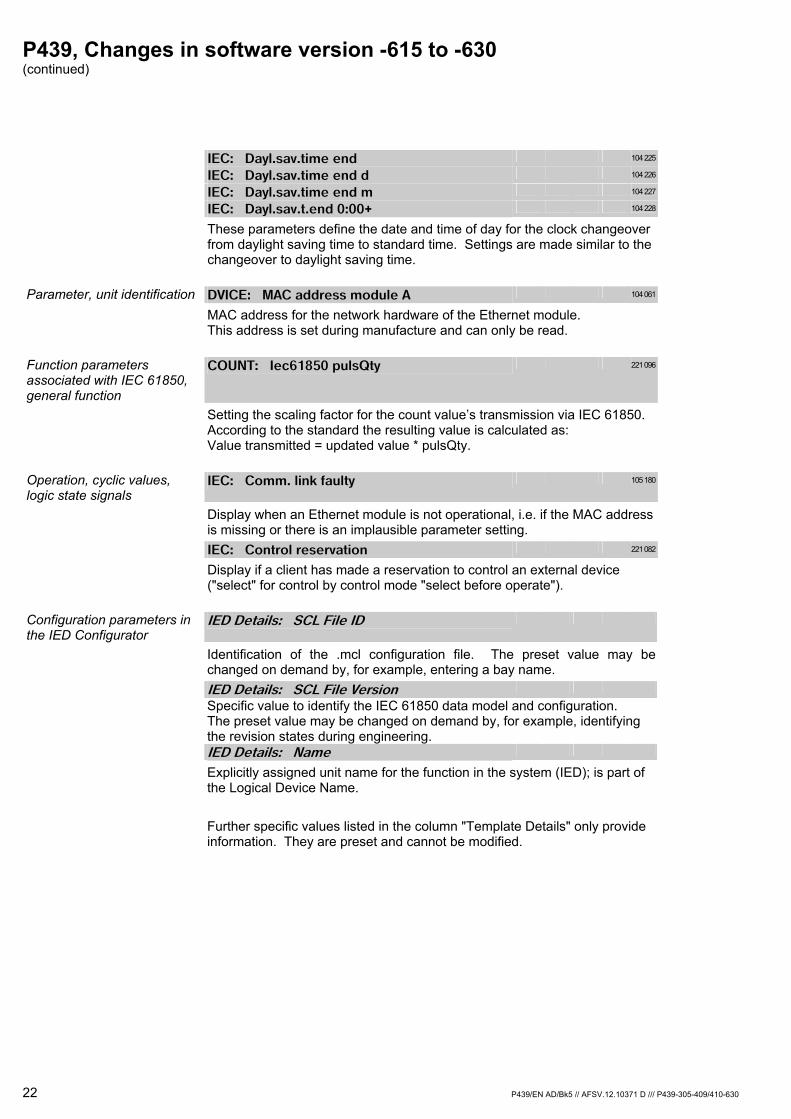
P439, Changes in software version -615 to -630 (continued)
22 P439/EN AD/Bk5 // AFSV.12.10371 D /// P439-305-409/410-630
IEC: Dayl.sav.time end 104 225
IEC: Dayl.sav.time end d 104 226
IEC: Dayl.sav.time end m 104 227
IEC: Dayl.sav.t.end 0:00+ 104 228
These parameters define the date and time of day for the clock changeover from daylight saving time to standard time. Settings are made similar to the changeover to daylight saving time.
Parameter, unit identification DVICE: MAC address module A 104 061
MAC address for the network hardware of the Ethernet module. This address is set during manufacture and can only be read.
Function parameters associated with IEC 61850, general function
COUNT: Iec61850 pulsQty 221 096
Setting the scaling factor for the count value’s transmission via IEC 61850. According to the standard the resulting value is calculated as: Value transmitted = updated value * pulsQty.
Operation, cyclic values, logic state signals
IEC: Comm. link faulty 105 180
Display when an Ethernet module is not operational, i.e. if the MAC address is missing or there is an implausible parameter setting.
IEC: Control reservation 221 082
Display if a client has made a reservation to control an external device ("select" for control by control mode "select before operate").
Configuration parameters in the IED Configurator
IED Details: SCL File ID
Identification of the .mcl configuration file. The preset value may be changed on demand by, for example, entering a bay name.
IED Details: SCL File Version
Specific value to identify the IEC 61850 data model and configuration. The preset value may be changed on demand by, for example, identifying the revision states during engineering.
IED Details: Name
Explicitly assigned unit name for the function in the system (IED); is part of the Logical Device Name.
Further specific values listed in the column "Template Details" only provide
information. They are preset and cannot be modified.

P439, Changes in software version -615 to -630 (continued)
P439/EN AD/Bk5 // AFSV.12.10371 D /// P439-305-409/410-630 23
Communications: Connected Sub-Network
Optional name available to identify the Ethernet. Communications: Access Point
Part of the communications control; preset, cannot be modified. Communications: IP Address
Explicitly assigned IP address of the unit for the server function in the system.
Communications: SubNet Mask
The subnet mask defines which part of the IP address is addressed by the sub-network and which part by the device that is logged-on to the network.
Communications: Gateway Address
This parameter defines the IPv4 address of the network gateway for communication links to clients outside of the local network.
Communications: Media
Network hardware provided as fiber optics or twisted pair copper wires. Communications: TCP Keepalive
Communication monitoring at TCP level; preset. Communications: Database Lock Timeout
Return time period for setting procedures that have commenced; preset. SNTP: Poll Rate (seconds)
Polling interval for clock synchronization; preset. SNTP: Accepted Stratum level
Quality criterion to accept an SNTP server for clock synchronization; preset, cannot be modified.
SNTP: IP Address
IP address of the preferred server used for clock synchronization. SNTP: virtual key "Use Anycast"
Appointing any server in the local network to provide clock synchronization.
Further specific values listed in the column "External server parameters" may be accepted when imported from an XML configuration file.
Dataset Definitions: Name
Explicitly assigned name for the dataset. Dataset Definitions: Location
Saving datasets at System\LLN0 is compulsory. Dataset Definitions: Contents
Content (data objects, data attributes) of a dataset Dataset Definitions: Display “GOOSE Capacity”
Checking the length of a dataset for less than 1500 bytes to permit transmission in GOOSE messages. The display is irrelevant when the dataset is only used in reports.
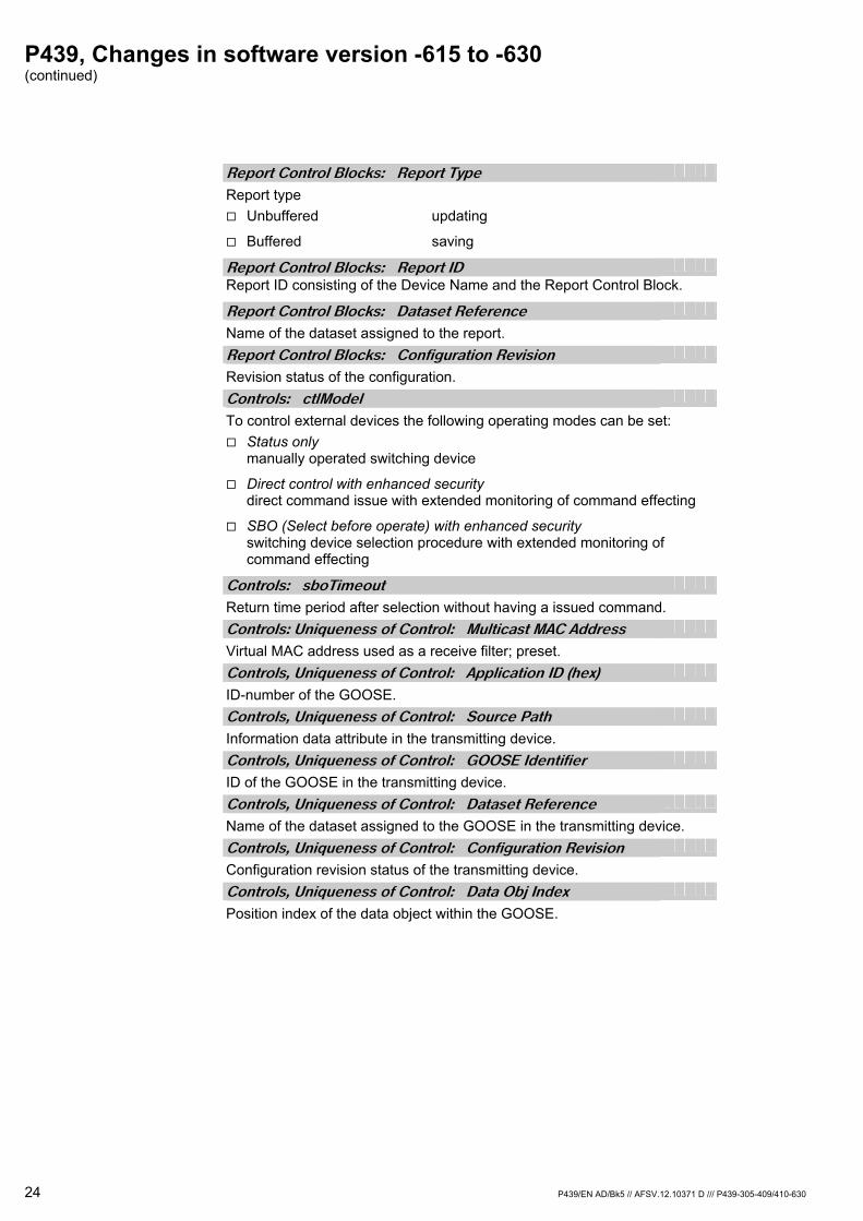
P439, Changes in software version -615 to -630 (continued)
24 P439/EN AD/Bk5 // AFSV.12.10371 D /// P439-305-409/410-630
Report Control Blocks: Report Type
Report type Unbuffered updating
Buffered saving
Report Control Blocks: Report ID
Report ID consisting of the Device Name and the Report Control Block. Report Control Blocks: Dataset Reference
Name of the dataset assigned to the report. Report Control Blocks: Configuration Revision
Revision status of the configuration. Controls: ctlModel
To control external devices the following operating modes can be set: Status only
manually operated switching device
Direct control with enhanced security direct command issue with extended monitoring of command effecting
SBO (Select before operate) with enhanced security switching device selection procedure with extended monitoring of command effecting
Controls: sboTimeout
Return time period after selection without having a issued command. Controls: Uniqueness of Control: Multicast MAC Address
Virtual MAC address used as a receive filter; preset. Controls, Uniqueness of Control: Application ID (hex)
ID-number of the GOOSE. Controls, Uniqueness of Control: Source Path
Information data attribute in the transmitting device. Controls, Uniqueness of Control: GOOSE Identifier
ID of the GOOSE in the transmitting device. Controls, Uniqueness of Control: Dataset Reference
Name of the dataset assigned to the GOOSE in the transmitting device. Controls, Uniqueness of Control: Configuration Revision
Configuration revision status of the transmitting device. Controls, Uniqueness of Control: Data Obj Index
Position index of the data object within the GOOSE.
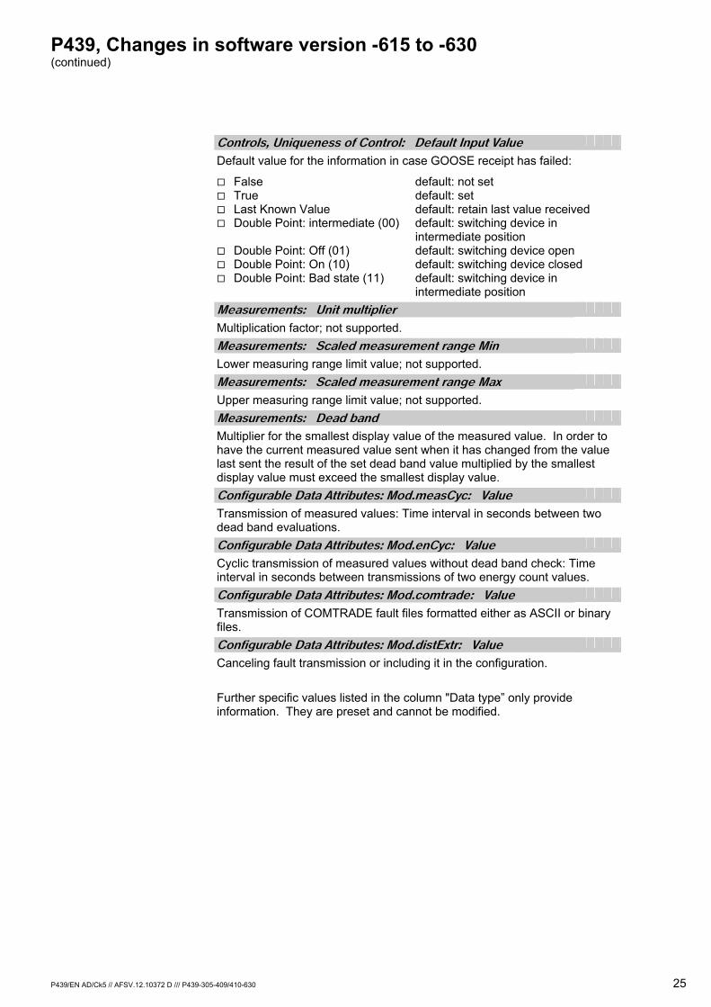
P439, Changes in software version -615 to -630 (continued)
P439/EN AD/Ck5 // AFSV.12.10372 D /// P439-305-409/410-630 25
Controls, Uniqueness of Control: Default Input Value
Default value for the information in case GOOSE receipt has failed:
False default: not set True default: set Last Known Value default: retain last value received Double Point: intermediate (00) default: switching device in
intermediate position Double Point: Off (01) default: switching device open Double Point: On (10) default: switching device closed Double Point: Bad state (11) default: switching device in
intermediate position
Measurements: Unit multiplier
Multiplication factor; not supported. Measurements: Scaled measurement range Min
Lower measuring range limit value; not supported. Measurements: Scaled measurement range Max
Upper measuring range limit value; not supported. Measurements: Dead band
Multiplier for the smallest display value of the measured value. In order to have the current measured value sent when it has changed from the value last sent the result of the set dead band value multiplied by the smallest display value must exceed the smallest display value.
Configurable Data Attributes: Mod.measCyc: Value
Transmission of measured values: Time interval in seconds between two dead band evaluations.
Configurable Data Attributes: Mod.enCyc: Value
Cyclic transmission of measured values without dead band check: Time interval in seconds between transmissions of two energy count values.
Configurable Data Attributes: Mod.comtrade: Value
Transmission of COMTRADE fault files formatted either as ASCII or binary files.
Configurable Data Attributes: Mod.distExtr: Value
Canceling fault transmission or including it in the configuration.
Further specific values listed in the column "Data type” only provide information. They are preset and cannot be modified.
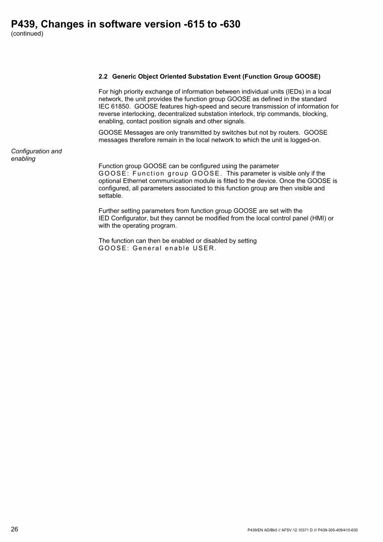
P439, Changes in software version -615 to -630 (continued)
26 P439/EN AD/Bk5 // AFSV.12.10371 D /// P439-305-409/410-630
2.2 Generic Object Oriented Substation Event (Function Group GOOSE)
For high priority exchange of information between individual units (IEDs) in a local network, the unit provides the function group GOOSE as defined in the standard IEC 61850. GOOSE features high-speed and secure transmission of information for reverse interlocking, decentralized substation interlock, trip commands, blocking, enabling, contact position signals and other signals.
GOOSE Messages are only transmitted by switches but not by routers. GOOSE messages therefore remain in the local network to which the unit is logged-on.
Configuration and enabling
Function group GOOSE can be configured using the parameter G O O S E : F u n c t i o n g r o u p G O O S E . This parameter is visible only if the optional Ethernet communication module is fitted to the device. Once the GOOSE is configured, all parameters associated to this function group are then visible and settable.
Further setting parameters from function group GOOSE are set with the IED Configurator, but they cannot be modified from the local control panel (HMI) or with the operating program.
The function can then be enabled or disabled by setting G O O S E : G e n e r a l e n a b l e U S E R .
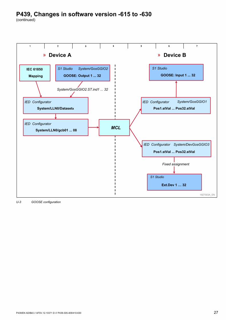
P439, Changes in software version -615 to -630 (continued)
P439/EN AD/Bk5 // AFSV.12.10371 D /// P439-305-409/410-630 27
» Device A » Device B
GOOSE: Output 1 ... 32
S1 Studio System/GosGGIO2
System/LLN0/gcb01 ... 08
System/LLN0/Datasetx
System/GosGGIO2.ST.ind1 ... 32
IEC 61850
Mapping
MCL
Pos1.stVal ... Pos32.stVal
System/DevGosGGIO3
Pos1.stVal ... Pos32.stVal
System/GosGGIO1
Ext.Dev 1 … 32
S1 Studio
GOOSE: Input 1 ... 32
S1 Studio
19Z7003A_EN
IED Configurator
IED ConfiguratorIED Configurator
IED Configurator
Fixed assignment
U-3 GOOSE configuration

P439, Changes in software version -615 to -630 (continued)
28 P439/EN AD/Bk5 // AFSV.12.10371 D /// P439-305-409/410-630
Sending GOOSE The unit can send up to eight different GOOSE messages that are managed in eight GOOSE Control Blocks (gcb01 to gcb08). Information content depends on the respective dataset assigned to GOOSE. The maximum size of a dataset to be sent by GOOSE is limited to 1500 bytes. A control display is shown by the IED Configurator to check this limit.
When defining the datasets for GOOSE it is advised to select the individual data attributes and not the overlapping data objects. By this the amount of data is kept within a limit and decoding is guaranteed on the receiving end.
In addition to the information included in the IEC 61850 data model an optional number of up to 32 signals can be selected from all the signals available in the unit to be transmitted via GOOSE, as it is also possible with reporting. Selection of binary state signals (shuttling to communications) is made by setting G O O S E : O u t p u t n f c t . a s s i g . (n = 1 to 32). The data object indexes defined for SigGGIO1 must follow the function assignments for the GOOSE outputs. The indexes GosGGIO2.ST.ind1 to GosGGIO2.ST.ind32 may then be included in the datasets just as the other data objects.
When a state change occurs with a selected state signal or a measured value changes which is greater than the dead band set for the relevant data point then the complete GOOSE is sent. There will be multiple send repetitions at ascending time periods. The first send repetition occurs at the given cycle time set with the parameter [ I C ] : M i n i m u m C y c l e T i m e . The cycles for the following send repetitions result from a conditional equation with the increment set with the parameter [ I C ] : I n c r e m e n t . Should no further state changes occur up to the time when the maximum cycle time has elapsed [ IC]: Maximum Cycle Time, then GOOSE will be sent cyclically at intervals as set for the maximum cycle time.
In order to have unambiguous identification of a GOOSE sent, characteristics such as [ IC]: Mult icast MAC Address, [ IC]: Appl icat ion ID (hex), [ IC]: VLAN Ident i f ier (hex), [ IC]: VLAN Pr ior i ty and [ IC]: GOOSE Identi f ier must be entered in the IED Configurator settings. Further characteristics are [ IC]: Dataset Reference and [ IC]: Configurat ion Revis ion.
Each GOOSE is given the state change index and the number of send repetitions.
P439, Changes in software version -615 to -630 (continued)
P439/EN AD/Bk5 // AFSV.12.10371 D /// P439-305-409/410-630 29
Receiving GOOSE With GOOSE up to 32 logic binary state signals as well as 32 two-pole contact position signals from external devices (Ext.Devxx) can be received. For each state signal or contact position signal to be received a specific GOOSE message is to be selected, which will contain the information wanted, by setting [ IC]: Mult icast MAC Address, [ IC]: Appl icat ion ID (hex), [ IC]: Source Path, [ IC]: GOOSE Ident i f ier and [ IC] : DataSet Reference. With the further setting of [ IC]: Data Obj Index / Type, which corresponds to the GOOSE position index and the information structure of the sending unit, the required information from the chosen GOOSE will be selected. The identification features "VLAN identifier" and [ I C ] : C o n f i g u r a t i o n R e v i s i o n that are also included in the GOOSE received will not be evaluated.
These parameters characterizing the information may be taken either from unit or project planning documentation of the sending unit or from a configuration file which is conform to IEC 61850. The IED Configurator will support the import of .IID, .SCD and .MCL files when the "browse function" (virtual key) is applied. The selection and acceptance of parameters from an existing project planning is distinguished by a simplified and very reliable data input.
Should the data type of the selected data object provide quality information then this can be evaluated. When activating [ I C ] : Q u a l i t y O b j I n d e x, the distance of the quality descriptor to the data object (if not preset) must be given as well as the quality criterion, which is to be tested. A signal is rejected when one of the bits ([ IC]: Inval id i ty Qual i ty b i ts , see displayed bar with bit state) is received as a set bit. These parameters are usually described in a configuration file and are accepted from there during an import action.
Each GOOSE includes time information on the duration of validity of its information. This corresponds to the double time period to the next GOOSE repetition. If the duration of validity has elapsed without this GOOSE having been received again (e.g. because of a fault in communications), the received signals will automatically be set to their respective default values [ I C ] : D e f a u l t I n p u t V a l u e . Which of the possible state values will set the desired security grade depends on the relevant application.
The following configuration (shuttling to the unit functions) of the logic state signals received from the logic node GosGGIO1 (G O O S E : I n p u t n f c t . a s s i g . , n = 1 to 32) is made on the basis of the selection table of the binary signal inputs (opto-coupler inputs). Contact position signals received from external devices (LN: DevGosGGIO3) are listed in the selection table for interlocking equations of the function group ILOCK, which are available to design a decentralized substation interlock.
The virtual key "Unmap" may be used to remove the link of a binary signal input to an external data point. In such a case all entries for this binary signal input are deleted.
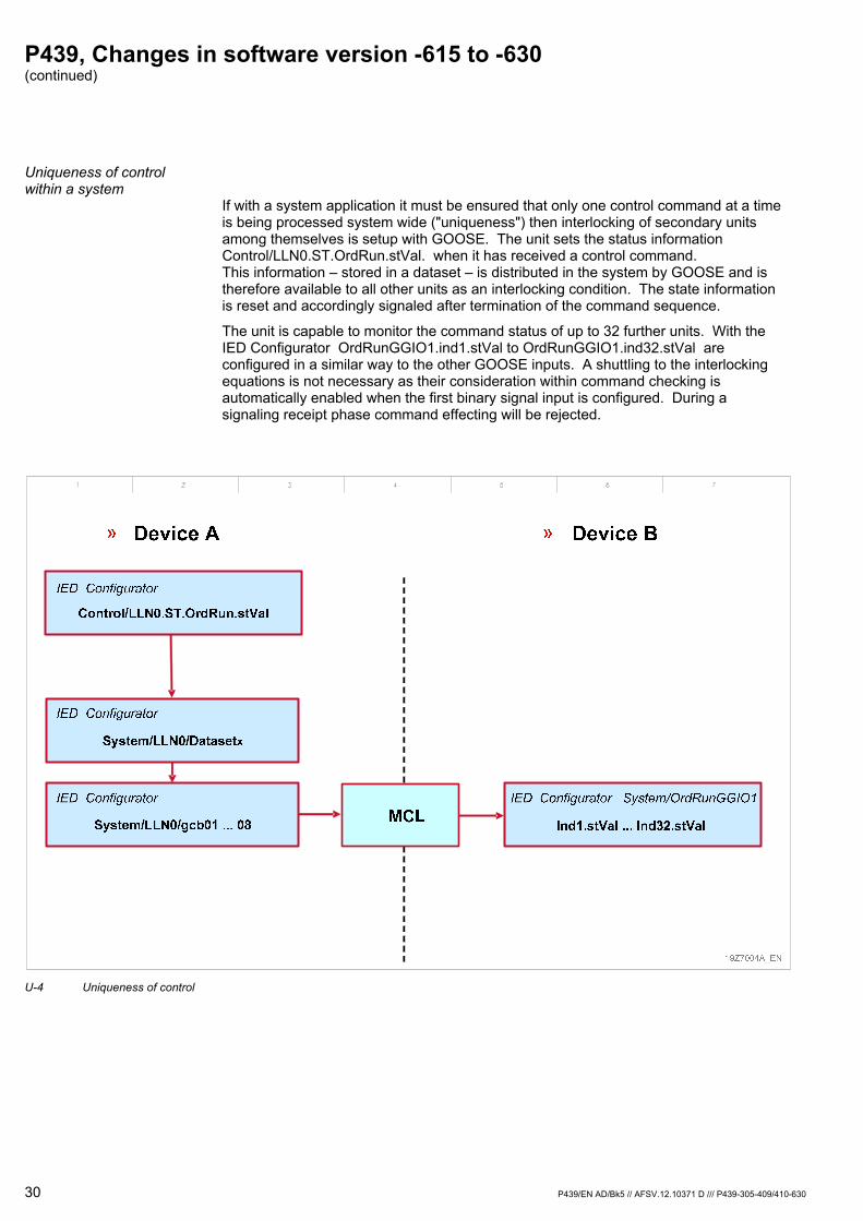
P439, Changes in software version -615 to -630 (continued)
30 P439/EN AD/Bk5 // AFSV.12.10371 D /// P439-305-409/410-630
Uniqueness of control within a system
If with a system application it must be ensured that only one control command at a time is being processed system wide ("uniqueness") then interlocking of secondary units among themselves is setup with GOOSE. The unit sets the status information Control/LLN0.ST.OrdRun.stVal. when it has received a control command. This information – stored in a dataset – is distributed in the system by GOOSE and is therefore available to all other units as an interlocking condition. The state information is reset and accordingly signaled after termination of the command sequence.
The unit is capable to monitor the command status of up to 32 further units. With the IED Configurator OrdRunGGIO1.ind1.stVal to OrdRunGGIO1.ind32.stVal are configured in a similar way to the other GOOSE inputs. A shuttling to the interlocking equations is not necessary as their consideration within command checking is automatically enabled when the first binary signal input is configured. During a signaling receipt phase command effecting will be rejected.
U-4 Uniqueness of control
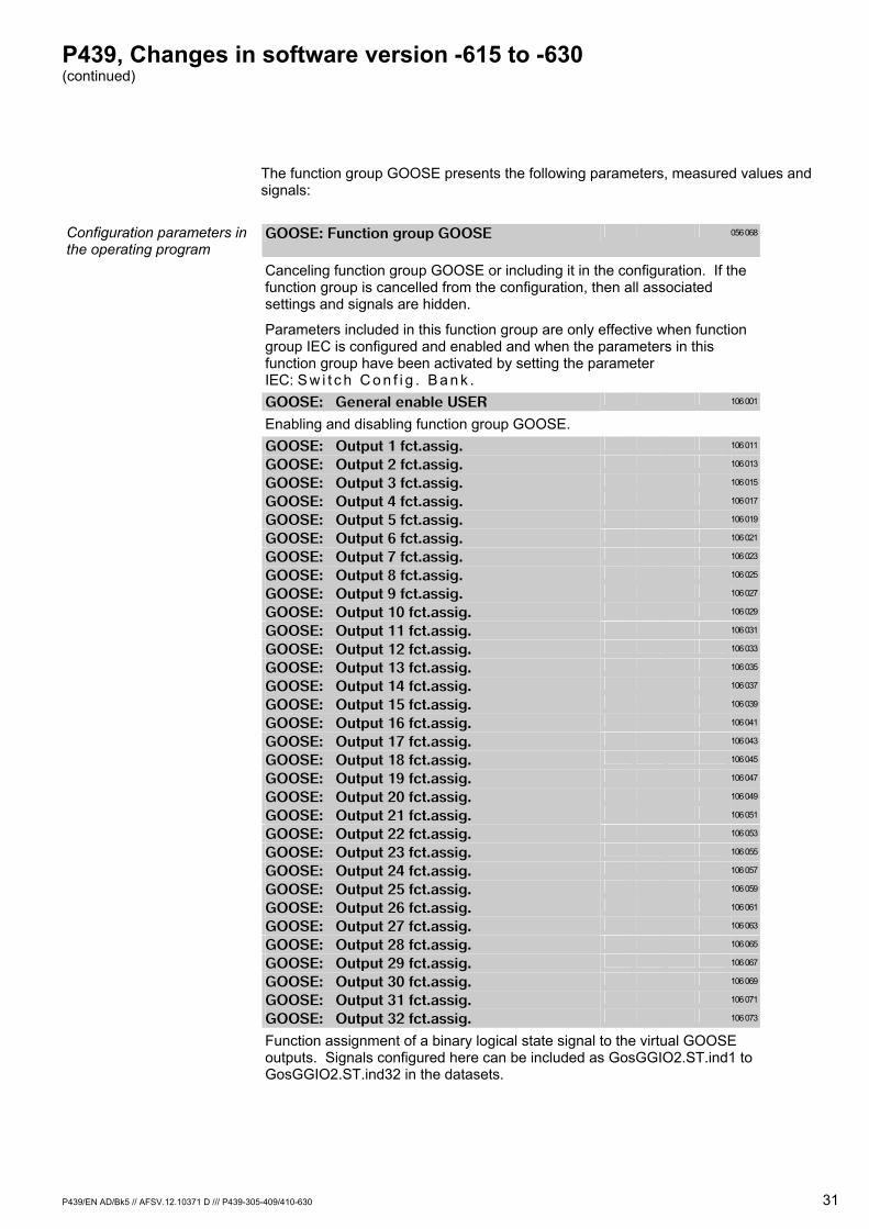
P439, Changes in software version -615 to -630 (continued)
P439/EN AD/Bk5 // AFSV.12.10371 D /// P439-305-409/410-630 31
The function group GOOSE presents the following parameters, measured values and signals:
Configuration parameters in the operating program
GOOSE: Function group GOOSE 056 068
Canceling function group GOOSE or including it in the configuration. If the function group is cancelled from the configuration, then all associated settings and signals are hidden.
Parameters included in this function group are only effective when function group IEC is configured and enabled and when the parameters in this function group have been activated by setting the parameter IEC: S w i t c h C o n f i g . B a n k .
GOOSE: General enable USER 106 001
Enabling and disabling function group GOOSE. GOOSE: Output 1 fct.assig. 106 011
GOOSE: Output 2 fct.assig. 106 013
GOOSE: Output 3 fct.assig. 106 015
GOOSE: Output 4 fct.assig. 106 017
GOOSE: Output 5 fct.assig. 106 019
GOOSE: Output 6 fct.assig. 106 021
GOOSE: Output 7 fct.assig. 106 023
GOOSE: Output 8 fct.assig. 106 025
GOOSE: Output 9 fct.assig. 106 027
GOOSE: Output 10 fct.assig. 106 029
GOOSE: Output 11 fct.assig. 106 031
GOOSE: Output 12 fct.assig. 106 033
GOOSE: Output 13 fct.assig. 106 035
GOOSE: Output 14 fct.assig. 106 037
GOOSE: Output 15 fct.assig. 106 039
GOOSE: Output 16 fct.assig. 106 041
GOOSE: Output 17 fct.assig. 106 043
GOOSE: Output 18 fct.assig. 106 045
GOOSE: Output 19 fct.assig. 106 047
GOOSE: Output 20 fct.assig. 106 049
GOOSE: Output 21 fct.assig. 106 051
GOOSE: Output 22 fct.assig. 106 053
GOOSE: Output 23 fct.assig. 106 055
GOOSE: Output 24 fct.assig. 106 057
GOOSE: Output 25 fct.assig. 106 059
GOOSE: Output 26 fct.assig. 106 061
GOOSE: Output 27 fct.assig. 106 063
GOOSE: Output 28 fct.assig. 106 065
GOOSE: Output 29 fct.assig. 106 067
GOOSE: Output 30 fct.assig. 106 069
GOOSE: Output 31 fct.assig. 106 071
GOOSE: Output 32 fct.assig. 106 073
Function assignment of a binary logical state signal to the virtual GOOSE outputs. Signals configured here can be included as GosGGIO2.ST.ind1 to GosGGIO2.ST.ind32 in the datasets.
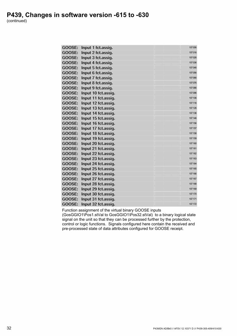
P439, Changes in software version -615 to -630 (continued)
32 P439/EN AD/Bk5 // AFSV.12.10371 D /// P439-305-409/410-630
GOOSE: Input 1 fct.assig. 107 006
GOOSE: Input 2 fct.assig. 107 016
GOOSE: Input 3 fct.assig. 107 026
GOOSE: Input 4 fct.assig. 107 036
GOOSE: Input 5 fct.assig. 107 046
GOOSE: Input 6 fct.assig. 107 056
GOOSE: Input 7 fct.assig. 107 066
GOOSE: Input 8 fct.assig. 107 076
GOOSE: Input 9 fct.assig. 107 086
GOOSE: Input 10 fct.assig. 107 096
GOOSE: Input 11 fct.assig. 107 106
GOOSE: Input 12 fct.assig. 107 116
GOOSE: Input 13 fct.assig. 107 126
GOOSE: Input 14 fct.assig. 107 136
GOOSE: Input 15 fct.assig. 107 146
GOOSE: Input 16 fct.assig. 107 156
GOOSE: Input 17 fct.assig. 107 157
GOOSE: Input 18 fct.assig. 107 158
GOOSE: Input 19 fct.assig. 107 159
GOOSE: Input 20 fct.assig. 107 160
GOOSE: Input 21 fct.assig. 107 161
GOOSE: Input 22 fct.assig. 107 162
GOOSE: Input 23 fct.assig. 107 163
GOOSE: Input 24 fct.assig. 107 164
GOOSE: Input 25 fct.assig. 107 165
GOOSE: Input 26 fct.assig. 107 166
GOOSE: Input 27 fct.assig. 107 167
GOOSE: Input 28 fct.assig. 107 168
GOOSE: Input 29 fct.assig. 107 169
GOOSE: Input 30 fct.assig. 107 170
GOOSE: Input 31 fct.assig. 107 171
GOOSE: Input 32 fct.assig. 107 172
Function assignment of the virtual binary GOOSE inputs (GosGGIO1\Pos1.stVal to GosGGIO1\Pos32.stVal) to a binary logical state signal on the unit so that they can be processed further by the protection, control or logic functions. Signals configured here contain the received and pre-processed state of data attributes configured for GOOSE receipt.

P439, Changes in software version -615 to -630 (continued)
P439/EN AD/Bk5 // AFSV.12.10371 D /// P439-305-409/410-630 33
Physical state signals GOOSE: Output 1 state 106 010
GOOSE: Output 2 state 106 012
GOOSE: Output 3 state 106 014
GOOSE: Output 4 state 106 016
GOOSE: Output 5 state 106 018
GOOSE: Output 6 state 106 020
GOOSE: Output 7 state 106 022
GOOSE: Output 8 state 106 024
GOOSE: Output 9 state 106 026
GOOSE: Output 10 state 106 028
GOOSE: Output 11 state 106 030
GOOSE: Output 12 state 106 032
GOOSE: Output 13 state 106 034
GOOSE: Output 14 state 106 036
GOOSE: Output 15 state 106 038
GOOSE: Output 16 state 106 040
GOOSE: Output 17 state 106 042
GOOSE: Output 18 state 106 044
GOOSE: Output 19 state 106 046
GOOSE: Output 20 state 106 048
GOOSE: Output 21 state 106 050
GOOSE: Output 22 state 106 052
GOOSE: Output 23 state 106 054
GOOSE: Output 24 state 106 056
GOOSE: Output 25 state 106 058
GOOSE: Output 26 state 106 060
GOOSE: Output 27 state 106 062
GOOSE: Output 28 state 106 064
GOOSE: Output 29 state 106 066
GOOSE: Output 30 state 106 068
GOOSE: Output 31 state 106 070
GOOSE: Output 32 state 106 072
Display of the virtual binary GOOSE output state.
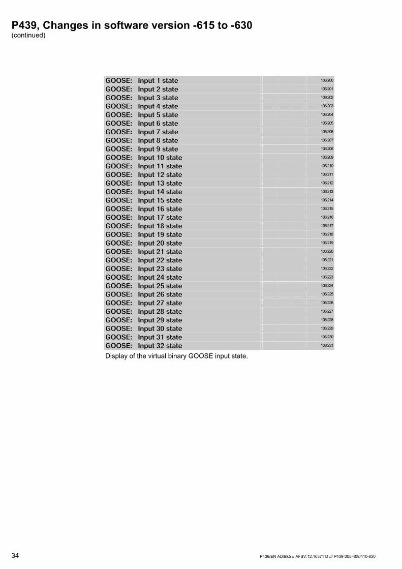
P439, Changes in software version -615 to -630 (continued)
34 P439/EN AD/Bk5 // AFSV.12.10371 D /// P439-305-409/410-630
GOOSE: Input 1 state 106 200
GOOSE: Input 2 state 106 201
GOOSE: Input 3 state 106 202
GOOSE: Input 4 state 106 203
GOOSE: Input 5 state 106 204
GOOSE: Input 6 state 106 205
GOOSE: Input 7 state 106 206
GOOSE: Input 8 state 106 207
GOOSE: Input 9 state 106 208
GOOSE: Input 10 state 106 209
GOOSE: Input 11 state 106 210
GOOSE: Input 12 state 106 211
GOOSE: Input 13 state 106 212
GOOSE: Input 14 state 106 213
GOOSE: Input 15 state 106 214
GOOSE: Input 16 state 106 215
GOOSE: Input 17 state 106 216
GOOSE: Input 18 state 106 217
GOOSE: Input 19 state 106 218
GOOSE: Input 20 state 106 219
GOOSE: Input 21 state 106 220
GOOSE: Input 22 state 106 221
GOOSE: Input 23 state 106 222
GOOSE: Input 24 state 106 223
GOOSE: Input 25 state 106 224
GOOSE: Input 26 state 106 225
GOOSE: Input 27 state 106 226
GOOSE: Input 28 state 106 227
GOOSE: Input 29 state 106 228
GOOSE: Input 30 state 106 229
GOOSE: Input 31 state 106 230
GOOSE: Input 32 state 106 231
Display of the virtual binary GOOSE input state.

P439, Changes in software version -615 to -630 (continued)
P439/EN AD/Bk5 // AFSV.12.10371 D /// P439-305-409/410-630 35
Logic state signals GOOSE: Ext.Dev01 position 109 000
State of the virtual two-pole GOOSE input, representing the state of an external device.
(Addresses 109 000,109 005…109 175 for the external devices Dev01 to Dev32.)
GOOSE: Ext.Dev01 open 109 001
Binary open state of the virtual two-pole GOOSE input, representing the state of an external device.
(Addresses 109 001,109 006…109 176 for the external devices Dev01 to Dev32.)
GOOSE: Ext.Dev01 closed 109 002
Binary closed state of the virtual two-pole GOOSE input, representing the state of an external device.
(Addresses 109 002,109 007…109 177 for the external devices Dev01 to Dev32.)
GOOSE: Ext.Dev01 interm.pos 109 003
Binary intermediate position state of the virtual two-pole GOOSE input, representing the state of an external device.
(Addresses 109 003,109 008…109 178 for the external devices Dev01 to Dev32.)
GOOSE: IED01 link faulty 107 180
Display whether GOOSE receipt of the configured signal is faulty or not available. To each GOOSE the GOOSE sending device will attach a validity stamp, up to which a repetition of GOOSE will be carried out independently of a change of state. Thus the unit monitors the time interval before the reception of the next state signal.
(Addresses 107 180…107 215 for IED01 to IED32.)
GOOSE: ExtDev01 link faulty 107 216
Display whether GOOSE receipt of the configured external device is faulty or not available. To each GOOSE the GOOSE sending device will attach a validity stamp, up to which a repetition of GOOSE will be carried out independently of a change of state. Thus the unit monitors the time interval before the reception of the next state signal.
(Addresses 107 216…107 247 for the external devices Dev01 to Dev32.)
GOOSE: IED link faulty 107 250
Display that appears as soon as receipt of at least one of the configured GOOSEs is faulty or not available. To each GOOSE the GOOSE sending device will attach a validity stamp, up to which a repetition of GOOSE will be carried out independently of a change of state. Thus the unit monitors the time interval before the reception of the next state signal.
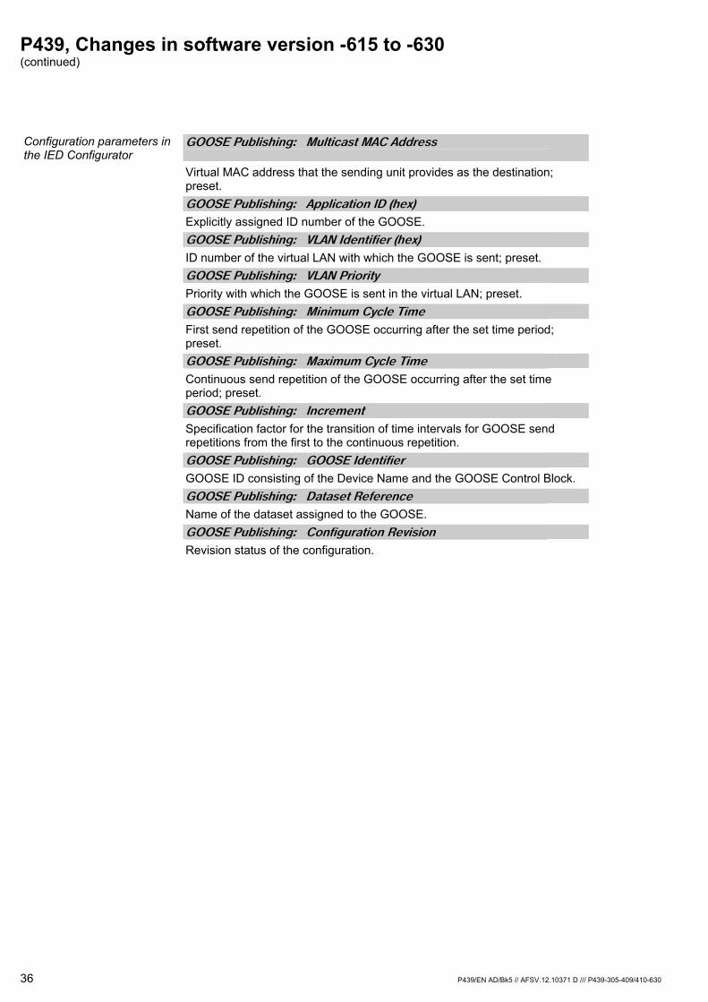
P439, Changes in software version -615 to -630 (continued)
36 P439/EN AD/Bk5 // AFSV.12.10371 D /// P439-305-409/410-630
Configuration parameters in the IED Configurator
GOOSE Publishing: Multicast MAC Address
Virtual MAC address that the sending unit provides as the destination; preset.
GOOSE Publishing: Application ID (hex)
Explicitly assigned ID number of the GOOSE. GOOSE Publishing: VLAN Identifier (hex)
ID number of the virtual LAN with which the GOOSE is sent; preset. GOOSE Publishing: VLAN Priority
Priority with which the GOOSE is sent in the virtual LAN; preset. GOOSE Publishing: Minimum Cycle Time
First send repetition of the GOOSE occurring after the set time period; preset.
GOOSE Publishing: Maximum Cycle Time
Continuous send repetition of the GOOSE occurring after the set time period; preset.
GOOSE Publishing: Increment
Specification factor for the transition of time intervals for GOOSE send repetitions from the first to the continuous repetition.
GOOSE Publishing: GOOSE Identifier
GOOSE ID consisting of the Device Name and the GOOSE Control Block. GOOSE Publishing: Dataset Reference
Name of the dataset assigned to the GOOSE. GOOSE Publishing: Configuration Revision
Revision status of the configuration.

P439, Changes in software version -615 to -630 (continued)
P439/EN AD/Bk5 // AFSV.12.10371 D /// P439-305-409/410-630 37
GOOSE Publishing: Multicast MAC Address
Virtual MAC address used as a receive filter; preset. GOOSE Publishing: Application ID (hex)
ID-number of the GOOSE. GOOSE Publishing: Source Path
Information data attribute in the transmitting device. GOOSE Publishing: GOOSE Identifier
ID of the GOOSE in the transmitting device. GOOSE Publishing: Dataset Reference
Name of the dataset assigned to the GOOSE in the transmitting device. GOOSE Publishing: Configuration Revision
Configuration revision status of the transmitting device. GOOSE Publishing: Data Obj Index
Position index of the data object within the GOOSE. GOOSE Publishing: Data Type
Structure of the data object; possible settings:
Unknown Unknown Boolean Boolean Int8 integer, 8 digits Int16 integer, 16 digits Int32 integer, 32 digits UInt8 positive integer, 8 digits UInt16 positive integer, 16 digits UInt32 positive integer, 32 digits Float floating-point number BStr2 binary state, with 2 digits SPS single-pole signal DPS two-pole signal
GOOSE Publishing: Quality Obj Index
Distance of the quality descriptor to the data object if not preset. The quality of the received information is to be tested if such has been configured.
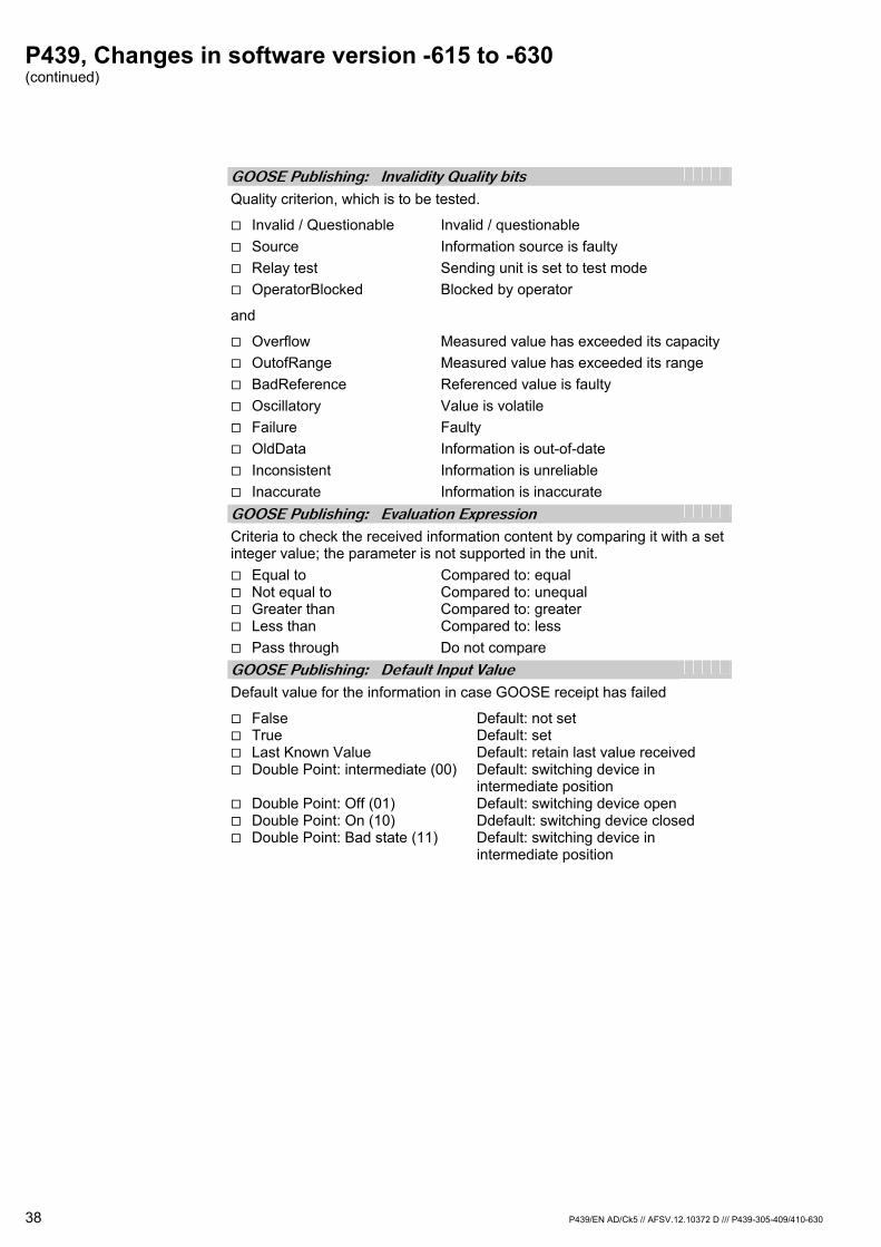
P439, Changes in software version -615 to -630 (continued)
38 P439/EN AD/Ck5 // AFSV.12.10372 D /// P439-305-409/410-630
GOOSE Publishing: Invalidity Quality bits
Quality criterion, which is to be tested.
Invalid / Questionable Invalid / questionable Source Information source is faulty Relay test Sending unit is set to test mode OperatorBlocked Blocked by operator
and
Overflow Measured value has exceeded its capacity OutofRange Measured value has exceeded its range BadReference Referenced value is faulty Oscillatory Value is volatile Failure Faulty OldData Information is out-of-date Inconsistent Information is unreliable Inaccurate Information is inaccurate
GOOSE Publishing: Evaluation Expression
Criteria to check the received information content by comparing it with a set integer value; the parameter is not supported in the unit.
Equal to Compared to: equal Not equal to Compared to: unequal Greater than Compared to: greater Less than Compared to: less Pass through Do not compare
GOOSE Publishing: Default Input Value
Default value for the information in case GOOSE receipt has failed
False Default: not set True Default: set Last Known Value Default: retain last value received Double Point: intermediate (00) Default: switching device in
intermediate position Double Point: Off (01) Default: switching device open Double Point: On (10) Ddefault: switching device closed Double Point: Bad state (11) Default: switching device in
intermediate position
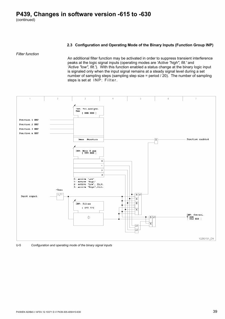
P439, Changes in software version -615 to -630 (continued)
P439/EN AD/Bk5 // AFSV.12.10371 D /// P439-305-409/410-630 39
2.3 Configuration and Operating Mode of the Binary Inputs (Function Group INP)
Filter function An additional filter function may be activated in order to suppress transient interference peaks at the logic signal inputs (operating modes are 'Active "high", filt.' and 'Active "low", filt.'). With this function enabled a status change at the binary logic input is signaled only when the input signal remains at a steady signal level during a set number of sampling steps (sampling step size = period / 20). The number of sampling steps is set at I N P : F i l t e r .
U-5 Configuration and operating mode of the binary signal inputs
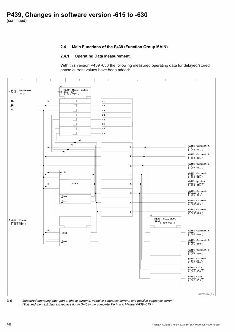
P439, Changes in software version -615 to -630 (continued)
40 P439/EN AD/Bk5 // AFSV.12.10371 D /// P439-305-409/410-630
2.4 Main Functions of the P439 (Function Group MAIN)
2.4.1 Operating Data Measurement
With this version P439 -630 the following measured operating data for delayed/stored phase current values have been added:
MAIN: Phasesequence[ 010 049 ]
49Z7001A_EN
MAIN: Hardwarefault
306 618
Ineg
Ipos
IA
IB
IC
MAIN: Meas. Valuerel. IP[ 011 030 ]
C
C1
C2
C3
C4
C5
C6
C7
C8
Imax
Imin
1 MAIN: Current Ap.u.[ 005 041 ]
MAIN: Inom C.T.prim.
[ 010 001 ]
2
3
4
5
6
7
8
MAIN: Current Bp.u.[ 006 041 ]
MAIN: Current Cp.u.[ 007 041 ]
MAIN: Current (IP) p.u.[ 005 011 ]
MAIN: Current Cprim.[ 007 040 ]
MAIN: Current Aprim.[ 005 040 ]
MAIN: Current Bprim.[ 006 040 ]
MAIN: Activepower P p.u.[ 005 051 ]
MAIN: CurrentIP,min p.u.[ 005 056 ]
MAIN: CurrentIneg p.u.[ 009 015 ]
MAIN: CurrentIpos p.u.[ 009 016 ]
MAIN: Curr.IP,max prim.[ 005 050 ]
MAIN: Curr.IP,min prim.[ 005 055 ]
MAIN: Current (IP) prim.[ 005 010 ]
COMP
+++
U-6 Measured operating data, part 1: phase currents, negative-sequence current, and positive-sequence current
(This and the next diagram replace figure 3-45 in the complete Technical Manual P439 -615.)

P439, Changes in software version -615 to -630 (continued)
P439/EN AD/Bk5 // AFSV.12.10371 D /// P439-305-409/410-630 41
MAIN: General reset EXT[ 005 255 ]
MAIN: Reset IP,max,st.USER[ 003 033 ]
0
1
0: don`t execute1: execute
MAIN: Reset IP,max,st. EXT[ 005 211 ]
MAIN: Settl. t.IP,max,del[ 010 113 ]
R
MAIN: Inom C.T.prim.
[ 010 001 ]
MAIN: Current A p.u.[ 005 041 ]
MAIN: Current B p.u.[ 006 041 ]
MAIN: Current C p.u.[ 007 041 ]
MAIN: CurrentIP,max p.u.[ 005 051 ]
MAIN: IP,max p.u.,demand[ 005 037 ]
MAIN: IP,maxp.u.,demand.st[ 005 035 ]
MAIN: Generalreset USER[ 003 002 ]1: execute
R
R
R
MAIN: IA p.u.,demand [ 006 235 ]
MAIN: IB p.u.,demand[ 006 236 ]
MAIN: IC p.u.,demand[ 006 237 ]
MAIN: IA p.u.,demand stor.[ 006 232 ]
MAIN: IB p.u.,demand stor.[ 006 233 ]
MAIN: IC p.u.,demand stor.[ 006 234 ]
MAIN: IP,max prim.,demand[ 005 036 ]
MAIN: IP,maxprim,demand.st.[ 005 034 ]
MAIN: IA prim,demand [ 006 226 ]MAIN: IB prim,demand[ 006 227 ]
MAIN: IC prim,demand.[ 006 228 ]
MAIN: IA prim,demand stor.[ 006 223 ]
MAIN: IB prim,demand stor.[ 006 224 ]
MAIN: IC prim,demand stor.[ 006 225 ]
19Z6404A_EN
U-7 Measured operating data, part 2: delayed and stored measured current values (This and the previous diagram replace figure 3-45 in the complete Technical Manual P439 -615.)

P439, Changes in software version -615 to -630 (continued)
42 P439/EN AD/Bk5 // AFSV.12.10371 D /// P439-305-409/410-630
2.5 Fault Data Acquisition (Function Group FT_DA)
Calculation of the fault location after a short-duration grounding
As of version –616, the P439 will calculate the fault location after a short-duration grounding (e.g. a grounding through a relatively large resistor, possibly without a DIST phase starting or a general starting). This is done by determining all three phase-to-ground impedance values and then calculating the fault location based on the measuring loop reactance with the lowest impedance value. With the present version, P439 –630, this feature was again revised:
This mode of calculating a fault location is enabled by setting F T _ D A : M o d e C a l c u l a t i o n P S x to 'with GS or N' (see Fig. U-9). Then fault recording together with fault location will be started by an internal trigger signal. This internal trigger signal, with a fixed operate delay time of 100 ms, will be issued after a measured ground starting (IN> & VNG>) with the neutral point treatment set to 'isolated/compensated'. This internal trigger signal (given in the following diagram as: F T _ R C : T r i g g e r E or F T _ D A : T r i g g e r E ) is independent of the preset delay time tIN> (D I S T : t I N > P S x ).
49Z7004A_EN
MAIN: Neutr.pt.treat. PSx[ * ]
1: Low-imped.grounding
2: Isol./res.w.start.PG
3: Isol./res.w/ost. PG
4: Short-durat.ground.
DIST: Start.IN> triggered
303 502
DIST: tIN>elapsed
303 503
DIST: Start.VNG> triggered
303 504
DIST: IA>>triggered
303 511
DIST: IB>>triggered
303 512
DIST: IC>>triggered
303 513
DIST: VPP<triggered
303 509
DIST: Start.ZPP< triggered
303 510
DIST: Starting G303 507
DIST: Start.switch. to PG[ 040 052 ]
Parameter
set 1set 2set 3set 4
MAIN: Neutr.pt.treat. PSx010 048001 076001 077001 078
*
100ms 0 FT_RC: Trigger G310 058
FT_DA: Trigger G310 059
U-8 Evaluation of trigger signals (function group DIST)
(This diagram replaces figure 3-111 in the complete Technical Manual P439 -615.)
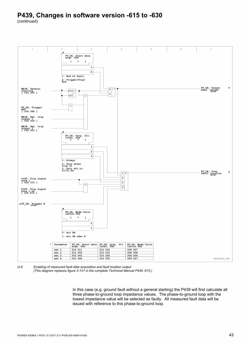
P439, Changes in software version -615 to -630 (continued)
P439/EN AD/Bk5 // AFSV.12.10371 D /// P439-305-409/410-630 43
49Z7005A_EN
FT_DA: Outp. flt.locat. PSx010 032010 033010 034010 035
FT_DA: Start dataacqu. PSx010 011010 042010 043010 044
Parameter
set 1set 2set 3set 4
FT_DA: Start dataacqu. PSx
[ * ]
FT_DA: Outp. flt.locat. PSx
[ * ]
1: Always
2: Only aftertrip t13: Only aft.tr.t1/t1,ze
1
2
3
1: End of fault
2: Trigger/Trip/End
1
2
FT_DA: Mode Calculation PSx
[ * ]
0: mit GA
1: mit GA oder N
0
1
FT_DA: Mode Calculation PSx008 007008 008008 009008 027
FT_DA: Trigger N310 059
FT_DA: TriggerEXT[ 036 088 ]
MAIN: Generalstarting[ 036 000 ]
MAIN: Gen. tripsignal 1[ 036 005 ]
MAIN: Gen. tripsignal 2[ 036 023 ]
DIST: Trip signalzone 1[ 035 072 ]
DIST: Trip signalzone 1,ze[ 035 074 ]
FT_DA: Outputmeas. values
305 050
FT_DA: Outp.fault location
305 051
U-9 Enabling of measured fault data acquisition and fault location output
(This diagram replaces figure 3-101 in the complete Technical Manual P439 -615.)
In this case (e.g. ground fault without a general starting) the P439 will first calculate all three phase-to-ground loop impedance values. The phase-to-ground loop with the lowest impedance value will be selected as faulty. All measured fault data will be issued with reference to this phase-to-ground loop.

P439, Changes in software version -615 to -630 (continued)
44 P439/EN AD/Bk5 // AFSV.12.10371 D /// P439-305-409/410-630
49Z7006A_EN
MAIN: Generalreset USER[ 003 002 ]1: execute
MAIN: ResetLED
306 020
≥1MAIN: Generalreset EXT[ 005 255 ]
FT_DA: Outputmeas. values
305 050
MAIN: Vnom V.T.prim.[ 010 002 ]
FT_DA: Trigger G310 059
MAIN: Inom C.T.prim.[ 010 001 ]
IA
IB
IC
R
R
R
C
C
DIST: Vmeas303 546
FT_DA: ImpedanceZAG, sec.
310 060
FT_DA: ImpedanceZBG, sec.
310 061
FT_DA: ImpedanceZCG, sec.
310 062
U-10 Determining the phase-to-ground loop impedances
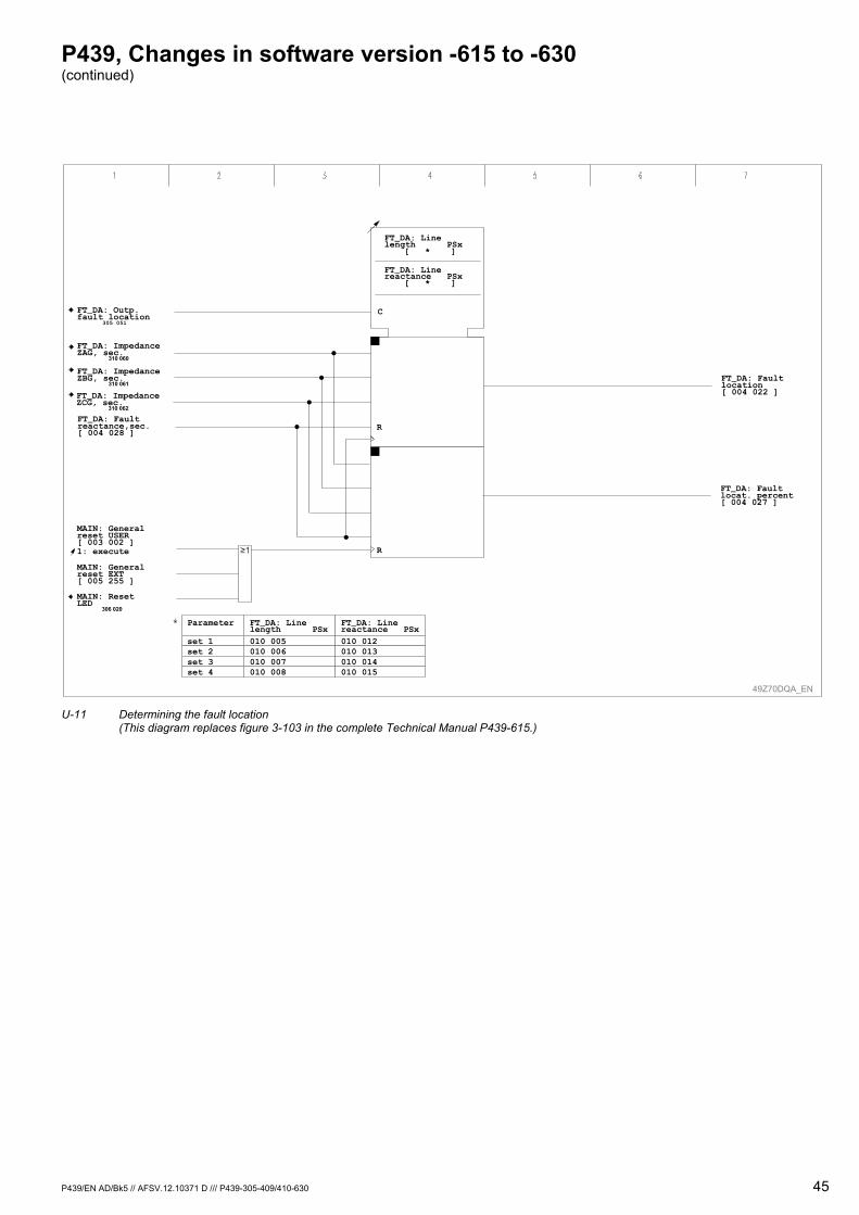
P439, Changes in software version -615 to -630 (continued)
P439/EN AD/Bk5 // AFSV.12.10371 D /// P439-305-409/410-630 45
49Z70DQA_EN
R
FT_DA: Faultlocation[ 004 022 ]
FT_DA: Faultlocat. percent[ 004 027 ]
C
FT_DA: ImpedanceZAG, sec.
310 060
FT_DA: ImpedanceZBG, sec.
310 061
FT_DA: ImpedanceZCG, sec.
310 062
R
MAIN: Generalreset USER[ 003 002 ]1: execute
MAIN: ResetLED
306 020
MAIN: Generalreset EXT[ 005 255 ]
FT_DA: Linereactance PSx010 012010 013010 014010 015
FT_DA: Linelength PSx010 005010 006010 007010 008
Parameter
set 1set 2set 3set 4
FT_DA: Outp.fault location
305 051
FT_DA: Faultreactance,sec.[ 004 028 ]
FT_DA: Linelength PSx
[ * ]
FT_DA: Linereactance PSx
[ * ]
U-11 Determining the fault location
(This diagram replaces figure 3-103 in the complete Technical Manual P439-615.)
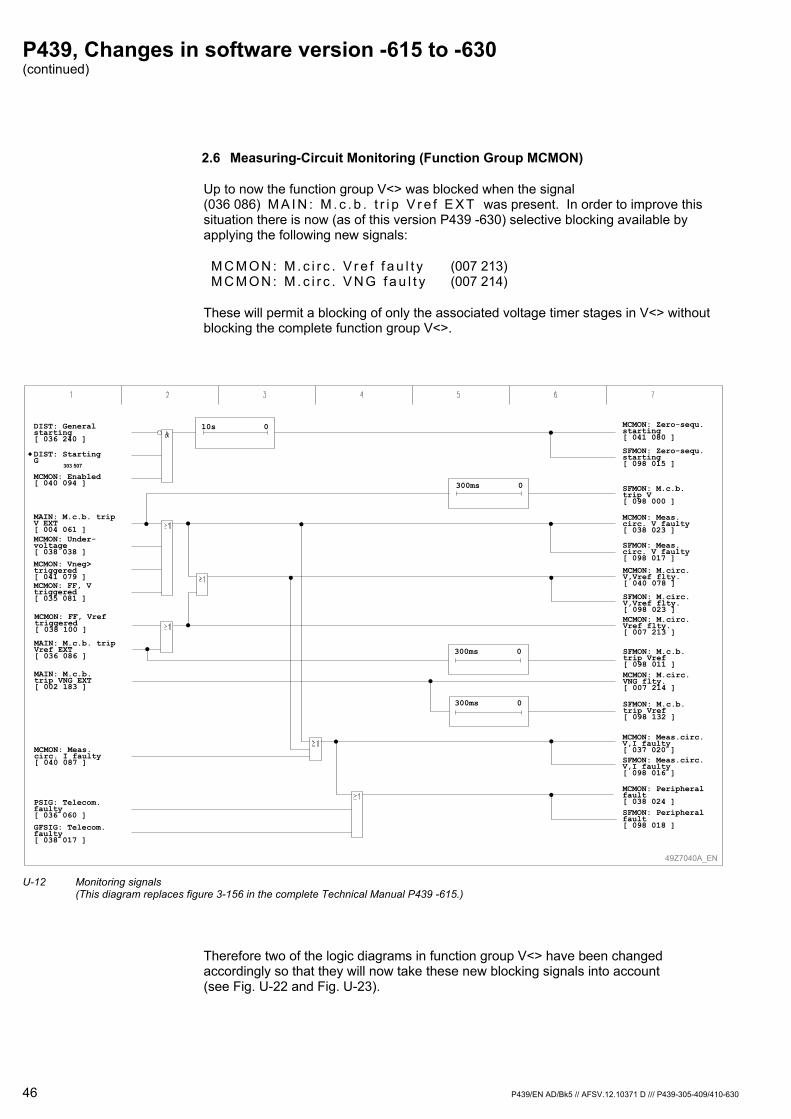
P439, Changes in software version -615 to -630 (continued)
46 P439/EN AD/Bk5 // AFSV.12.10371 D /// P439-305-409/410-630
2.6 Measuring-Circuit Monitoring (Function Group MCMON)
Up to now the function group V<> was blocked when the signal (036 086) M A I N : M . c . b . t r i p V r e f E X T was present. In order to improve this situation there is now (as of this version P439 -630) selective blocking available by applying the following new signals:
M C M O N : M . c i r c . V r e f f a u l t y (007 213) M C M O N : M . c i r c . V N G f a u l t y (007 214)
These will permit a blocking of only the associated voltage timer stages in V<> without blocking the complete function group V<>.
49Z7040A_EN
DIST: Generalstarting[ 036 240 ]
DIST: StartingG
303 507
MCMON: Enabled[ 040 094 ]
MCMON: Under-voltage[ 038 038 ]
MCMON: Vneg>triggered[ 041 079 ]MCMON: FF, Vtriggered[ 035 081 ]
MAIN: M.c.b. tripV EXT[ 004 061 ]
MCMON: Meas.circ. I faulty[ 040 087 ]
PSIG: Telecom.faulty[ 036 060 ]
GFSIG: Telecom.faulty[ 038 017 ]
MCMON: Zero-sequ.starting[ 041 080 ]
SFMON: Zero-sequ.starting[ 098 015 ]
SFMON: M.c.b.trip V[ 098 000 ]
MCMON: Meas.circ. V faulty[ 038 023 ]
MCMON: Meas.circ.V,I faulty[ 037 020 ]SFMON: Meas.circ.V,I faulty[ 098 016 ]
MCMON: Peripheralfault[ 038 024 ]SFMON: Peripheralfault[ 098 018 ]
SFMON: Meas.circ. V faulty[ 098 017 ]
300ms 0
10s 0
MCMON: FF, Vreftriggered[ 038 100 ]
MAIN: M.c.b. tripVref EXT[ 036 086 ]
MCMON: M.circ.V,Vref flty.[ 040 078 ]
SFMON: M.circ.V,Vref flty.[ 098 023 ]
SFMON: M.c.b.trip Vref[ 098 011 ]
300ms 0
MCMON: M.circ.Vref flty.[ 007 213 ]
MAIN: M.c.b.trip VNG EXT[ 002 183 ]
MCMON: M.circ.VNG flty.[ 007 214 ]
300ms 0 SFMON: M.c.b.trip Vref[ 098 132 ]
U-12 Monitoring signals
(This diagram replaces figure 3-156 in the complete Technical Manual P439 -615.)
Therefore two of the logic diagrams in function group V<> have been changed accordingly so that they will now take these new blocking signals into account (see Fig. U-22 and Fig. U-23).
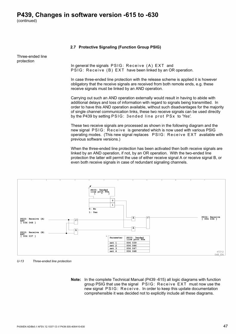
P439, Changes in software version -615 to -630 (continued)
P439/EN AD/Bk5 // AFSV.12.10371 D /// P439-305-409/410-630 47
2.7 Protective Signaling (Function Group PSIG)
Three-ended line protection
In general the signals P S I G : R e c e i v e ( A ) E X T and P S I G : R e c e i v e ( B ) E X T have been linked by an OR operation.
In case three-ended line protection with the release scheme is applied it is however obligatory that the receive signals are received from both remote ends, e.g. these receive signals must be linked by an AND operation.
Carrying out such an AND operation externally would result in having to abide with additional delays and loss of information with regard to signals being transmitted. In order to have this AND operation available, without such disadvantages for the majority of single channel communication links, these two receive signals can be used directly by the P439 by setting P S I G : 3 e n d e d l i n e p r o t P S x to 'Yes'.
These two receive signals are processed as shown in the following diagram and the new signal P S I G : R e c e i v e is generated which is now used with various PSIG operating modes. (This new signal replaces P S I G : R e c e i v e E X T available with previous software versions.)
When the three-ended line protection has been activated then both receive signals are linked by an AND operation, if not, by an OR operation. With the two-ended line protection the latter will permit the use of either receive signal A or receive signal B, or even both receive signals in case of redundant signaling channels.
PSIG: 3endedline prot PSx
[ * ]
0: No1: Yes
0
1
&
&&
47Z1204B_EN
PSIG: Receive (A)EXT[ 036 048 ]
PSIG: Receive[ 006 036 ]
PSIG: Receive (B)EXT[ 006 037 ]
PSIG: 3endedline prot PSx006 039006 046006 047006 048
Parameter
set 1set 2set 3set 4
U-13 Three-ended line protection
Note: In the complete Technical Manual (P439 -615) all logic diagrams with function group PSIG that use the signal P S I G : R e c e i v e E X T must now use the new signal P S I G : R e c e i v e . In order to keep this update documentation comprehensible it was decided not to explicitly include all these diagrams.
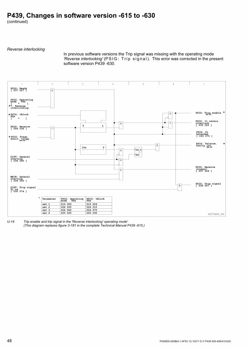
P439, Changes in software version -615 to -630 (continued)
48 P439/EN AD/Bk5 // AFSV.12.10371 D /// P439-305-409/410-630
Reverse interlocking In previous software versions the Trip signal was missing with the operating mode 'Reverse interlocking' (P S I G : T r i p s i g n a l ). This error was corrected in the present software version P439 -630.
PSIG: Trip enable305 157
PSIG: Ready[ 037 027 ]
PSIG: Operatingmode PSx[ * ]7: Reverseinterlocking
MAIN: Generalstarting[ 036 000 ]
49Z7088A_EN
DIST: Generalstarting[ 036 240 ]
PSIG: Frequ.monit. trigg.
305 152
PSIG: Receive[ 006 036 ]
PSIG: t1 revers.interlock[ 036 020 ]
PSIG: Receive(signal)[ 037 029 ]
PSIG: Telecom.faulty int.
305 151
PSIG: tBlockPSx[ * ]
S1
R1
1
0 t
10s 0
PSIG: Z1extended[ 035 075 ]
DIST: Trip signalZ1,ze[ 035 074 ]
PSIG: Trip signal[ 038 007 ]
PSIG: tBlockPSx015 024024 010024 070025 030
Parameter
set 1set 2set 3set 4
PSIG: Operatingmode PSx015 000024 000024 060025 020
U-14 Trip enable and trip signal in the 'Reverse interlocking' operating mode'
(This diagram replaces figure 3-181 in the complete Technical Manual P439 -615.)
P439, Changes in software version -615 to -630 (continued)
P439/EN AD/Bk5 // AFSV.12.10371 D /// P439-305-409/410-630 49
2.8 Auto-Reclosure Control (Function Group ARC)
With the present software version P439 -630 there is now an operative time 2 in addition to operative time 1 available.
2.8.1 High-Speed Reclosure (HSR)
When the ARC cycle starts, operative time 1 and operative time 2 are started. The starting conditions for the ARC cycle must drop out while both operative times are elapsing. This means that the circuit breaker must have opened so that a dead time is started. If both operative times are set at ≤ 25 ms, then ARC will not be ready in the event of starting; in the event of a trip, the reclaim time is started. ARC will be ready again when starting has dropped out without a subsequent trip. Operative time 1 has preference over operative time 2.
Should the circuit breaker fail to clear the fault within the operative times, the reclaim time will be started and a three-pole trip will occur (final trip). If the operative times have elapsed without a trip decision, then the ARC is ready again immediately after the general starting condition has dropped out.
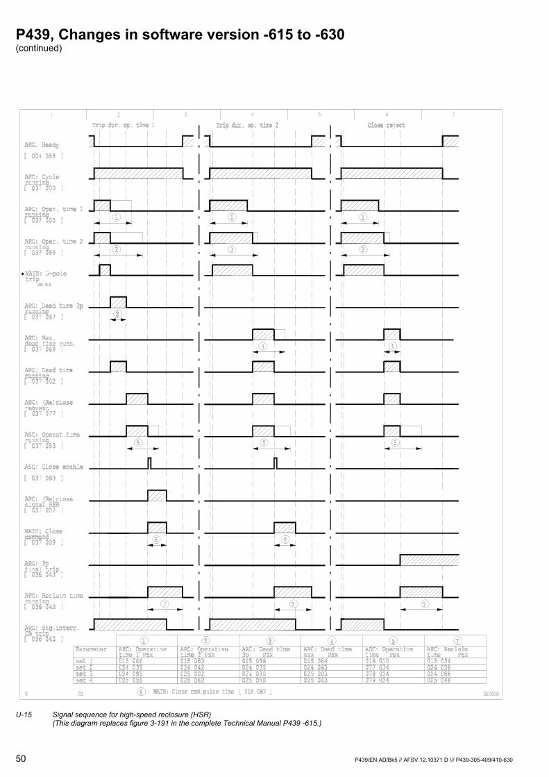
P439, Changes in software version -615 to -630 (continued)
50 P439/EN AD/Bk5 // AFSV.12.10371 D /// P439-305-409/410-630
U-15 Signal sequence for high-speed reclosure (HSR)
(This diagram replaces figure 3-191 in the complete Technical Manual P439 -615.)
P439, Changes in software version -615 to -630 (continued)
P439/EN AD/Bk5 // AFSV.12.10371 D /// P439-305-409/410-630 51
2.8.2 Time-Delayed Reclosure (TDR)
The TDR is started if either a new general starting condition or the trip of an external protection device (if configured accordingly) occurs while the reclaim time is elapsing. Operative times 1 and 2 are started. If the starting conditions for the TDR drop out while operative times 1 and 2 are elapsing, then the TDR dead time is started. The close command is issued once the dead time has elapsed.
If the fault is still present even after another reclosing, the TDR can be started again. This process can be repeated as often as allowed by the number of permitted TDRs. If the fault is still present after that, then a final trip occurs.
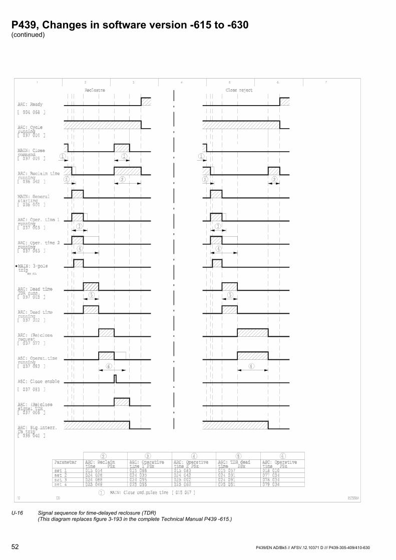
P439, Changes in software version -615 to -630 (continued)
52 P439/EN AD/Bk5 // AFSV.12.10371 D /// P439-305-409/410-630
U-16 Signal sequence for time-delayed reclosure (TDR)
(This diagram replaces figure 3-193 in the complete Technical Manual P439 -615.)
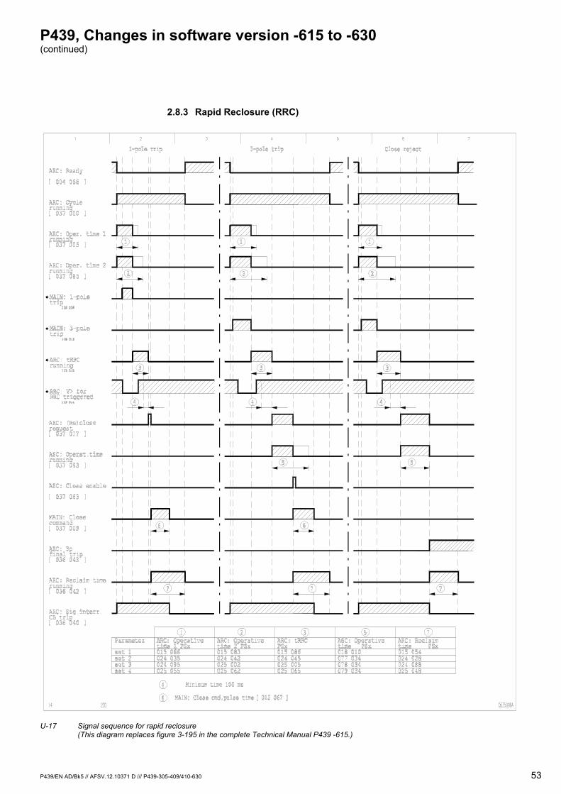
P439, Changes in software version -615 to -630 (continued)
P439/EN AD/Bk5 // AFSV.12.10371 D /// P439-305-409/410-630 53
2.8.3 Rapid Reclosure (RRC)
U-17 Signal sequence for rapid reclosure
(This diagram replaces figure 3-195 in the complete Technical Manual P439 -615.)
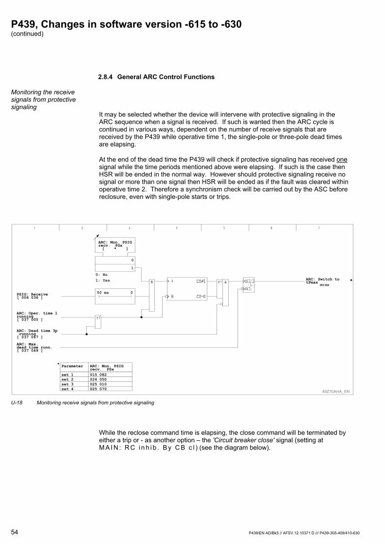
P439, Changes in software version -615 to -630 (continued)
54 P439/EN AD/Bk5 // AFSV.12.10371 D /// P439-305-409/410-630
2.8.4 General ARC Control Functions
Monitoring the receive signals from protective signaling
It may be selected whether the device will intervene with protective signaling in the ARC sequence when a signal is received. If such is wanted then the ARC cycle is continued in various ways, dependent on the number of receive signals that are received by the P439 while operative time 1, the single-pole or three-pole dead times are elapsing.
At the end of the dead time the P439 will check if protective signaling has received one signal while the time periods mentioned above were elapsing. If such is the case then HSR will be ended in the normal way. However should protective signaling receive no signal or more than one signal then HSR will be ended as if the fault was cleared within operative time 2. Therefore a synchronism check will be carried out by the ASC before reclosure, even with single-pole starts or trips.
49Z70AHA_EN
ARC: Mon. PSIGrecv. PSx015 082024 050025 010025 070
Parameter
set 1set 2set 3set 4
0
1
ARC: Mon. PSIGrecv. PSx[ * ]
0: No1: Yes
PSIG: Receive[ 006 036 ]
ARC: Oper. time 1running[ 037 005 ]
ARC: Dead time 3p running[ 037 067 ]
ARC: Max.dead time runn.[ 037 069 ]
ARC: Switch totPmax
303 024
50 ms 0
*
U-18 Monitoring receive signals from protective signaling
While the reclose command time is elapsing, the close command will be terminated by either a trip or - as another option – the 'Circuit breaker close' signal (setting at M A I N : R C i n h i b . B y C B c l ) (see the diagram below).

P439, Changes in software version -615 to -630 (continued)
P439/EN AD/Bk5 // AFSV.12.10371 D /// P439-305-409/410-630 55
49Z70ABA_EN
ARC: TDR deadtime PSx015 057024 031024 091025 051
ARC: No. permit.TDR PSx015 068024 037024 097025 057
ARC: Operating modePSx[ * ]
ARC: Operative time 1 PSx [ * ]
ARC: Enable RRCPSx[ * ]
ARC: Operative time 2 PSx [ * ]
ARC: Dead time 3p PSx [ * ]
ARC: Dead time max PSx [ * ]
ARC: TDR dead time PSx [ * ]
ARC: Reclaimtime PSx015 054024 028024 088025 048
ARC: tRRCPSx015 086024 045025 005025 065
ARC: No. permit. TDR PSx [ * ]
ARC: tRRC PSx [ * ]
ARC: Reclaim time PSx [ * ]
ARC: Parallel trip PSx [ * ]
ARC: Cycle running[ 037 000 ]
ARC: Oper. time 1 running[ 037 005 ]
ARC: Oper. time 2 running[ 037 065 ]
ARC: Dead time 3p running[ 037 067 ]
ARC: Max. dead time runn.[ 037 069 ]
ARC: Dead time running[ 037 002 ]
ARC: Dead time TDR runn.[ 037 003 ]
ARC: (Re)close request[ 037 077 ]
MAIN: RC inhib.by CB close[ 015 042 ]1: Yes
ARC: Operativetime 2 PSx015 083024 042025 002025 062
ARC: Operativetime 1 PSx015 066024 035024 095025 055
ARC: Dead timemax PSx015 084024 043025 003025 063
ARC: Dead time3p PSx015 056024 030024 090025 050
Parameter
set 1set 2set 3set 4
ARC: Paralleltrip PSx015 053024 027024 087025 047
SettingARC: Parallel trip PSx
0: Without function1: Parall. bloc.w/o ini2: Parall. bloc.w. init
Parameter
set 1set 2set 3set 4
ARC: Enable RRCPSx015 085024 044025 004025 065
Parameter
set 1set 2set 3set 4
ARC: Operatingmode PSx015 100015 101015 102015 103
Parameter
set 1set 2set 3set 4
Parameter
set 1set 2set 3set 4
Parameter
set 1set 2set 3set 4
MAIN: 1-pole trip306 006
ARC: General starting EXT[ 037 096 ]
MAIN: 3-pole trip306 013
ARC: Switch to tPmax303 024
ARC: V> for RRC triggered303 014
MAIN: Parallel trip EXT[ 037 019 ]
MAIN: General starting[ 036 000 ]
ARC: CB closed303 004
MAIN: Man. close command[ 037 068 ]
ASC: Close enable[ 037 083 ]
ASC: Close rejection[ 037 086 ]
ARC: Close command303 021
ARC: TDR permitted303 019
ARC: 3-pole transfer int.303 020
ARC: HSR A-B-C303 005
ARC: TDR303 006
ARC: 3-pole RRC303 007
ARC: tRRC running303 015
ARC: Reclaim time running[ 036 042 ]ARC: Sig.interr. CB trip[ 036 040 ]
ARC: 3p final trip[ 036 043 ]
ARC: (Re)close signal HSR[ 037 007 ]
ARC: (Re)close signal TDR[ 037 006 ]
ARC: Reclosure successful[ 036 062 ]
U-19 ARC sequence control (This diagram replaces figure 3-197 in the complete Technical Manual P439 -615.)

P439, Changes in software version -615 to -630 (continued)
56 P439/EN AD/Bk5 // AFSV.12.10371 D /// P439-305-409/410-630
2.9 Automatic Synchronism Check (Function Group ASC)
Voltage-checked The following operating modes for voltage checking can be selected separately for each parameter subset:
Vref but not V
V but not Vref
Not V and not Vref
Not V or not Vref
Vref & Z1 but not V
N V&Vref or V&n Vref
The 'N V&Vref or V&n Vref' operating mode has been newly implemented as of this software version, P439 -630.
The 'Vref & Z1 but not V' operating mode includes a further requirement, which specifies that the close request is issued during an ARC cycle and the cause of the fault for the previous protective trip lies inside the reach of impedance zone 1.
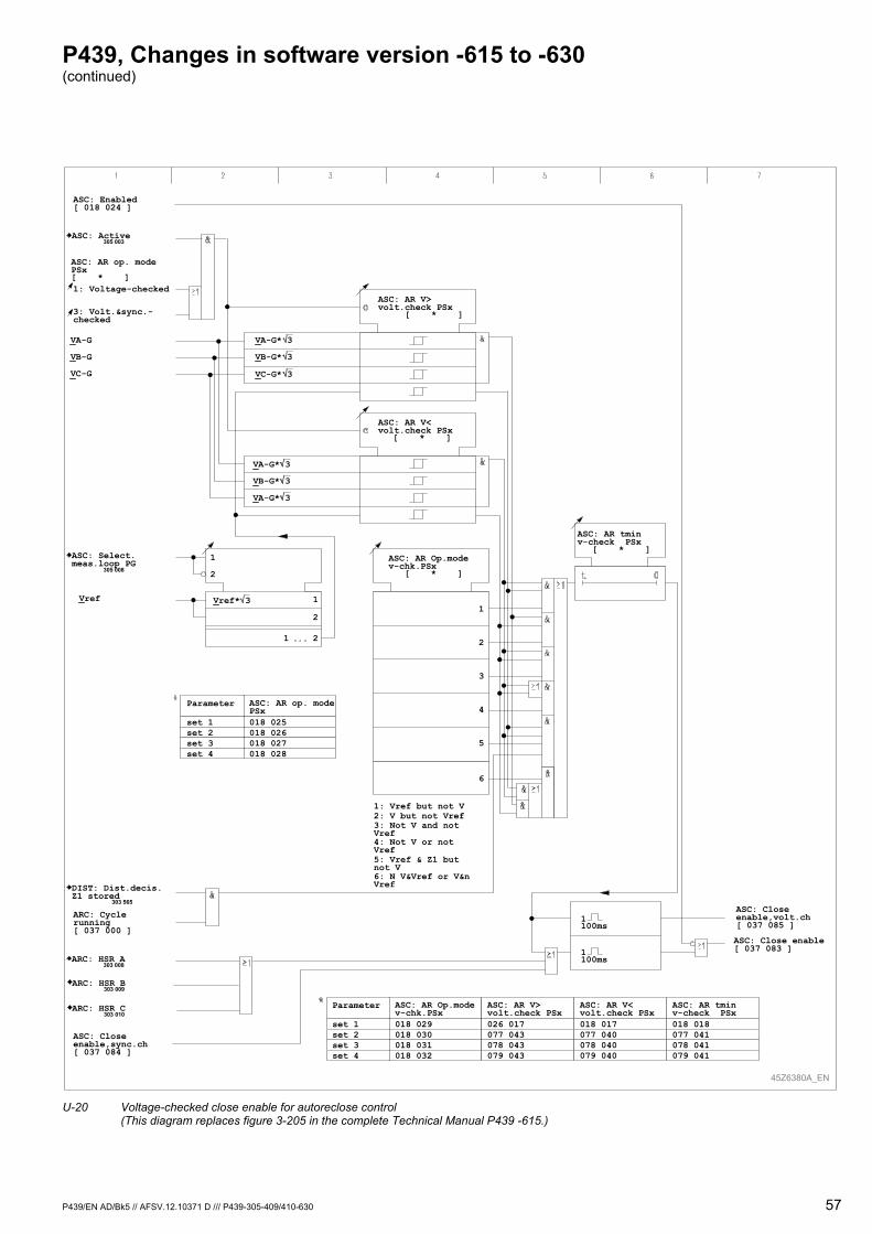
P439, Changes in software version -615 to -630 (continued)
P439/EN AD/Bk5 // AFSV.12.10371 D /// P439-305-409/410-630 57
45Z6380A_EN
ASC: AR V>volt.check PSx [ * ]
ASC: AR V<volt.check PSx
[ * ]
ASC: AR tminv-check PSx
[ * ]ASC: AR Op.modev-chk.PSx
[ * ]
ASC: AR op. modePSx[ * ]
1: Vref but not V2: V but not Vref3: Not V and notVref4: Not V or notVref5: Vref & Z1 butnot V6: N V&Vref or V&nVref
6
1
2
3
4
5
VA-G
VB-G
VC-G
ASC: Enabled[ 018 024 ]
1: Voltage-checked
Vref
ASC: AR op. modePSx018 025018 026018 027018 028
Parameter
set 1set 2set 3set 4
ASC: AR Op.modev-chk.PSx018 029018 030018 031018 032
Parameter
set 1set 2set 3set 4
ASC: AR V>volt.check PSx026 017077 043078 043079 043
ASC: AR V<volt.check PSx018 017077 040078 040079 040
ASC: AR tminv-check PSx018 018077 041078 041079 041
1
2
21
ASC: Close enable[ 037 083 ]
ASC: Closeenable,volt.ch[ 037 085 ]
ASC: Closeenable,sync.ch[ 037 084 ]
ARC: HSR C303 010
ARC: HSR A303 008
ARC: HSR B303 009
DIST: Dist.decis.Z1 stored
303 565
ARC: Cyclerunning[ 037 000 ]
ASC: Select.meas.loop PG
305 008
3: Volt.&sync.-checked
ASC: Active305 003
1
2
VA-G* 3
VB-G* 3
VC-G* 3
VA-G* 3
VB-G* 3
VA-G* 3
Vref* 3
1100ms
1100ms
U-20 Voltage-checked close enable for autoreclose control
(This diagram replaces figure 3-205 in the complete Technical Manual P439 -615.)
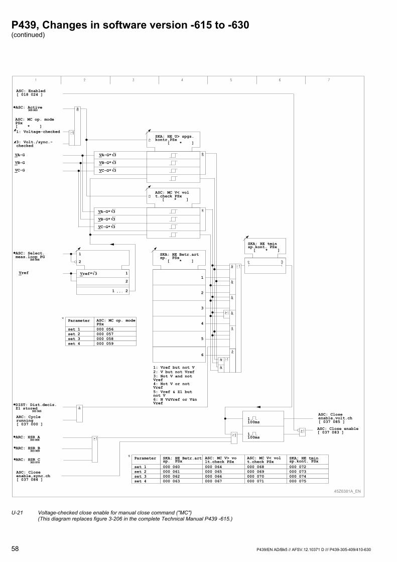
P439, Changes in software version -615 to -630 (continued)
58 P439/EN AD/Bk5 // AFSV.12.10371 D /// P439-305-409/410-630
45Z6381A_EN
SKA: HE U> spgs.kontr.PSx [ * ]
ASC: MC V< volt.check PSx
[ * ]
SKA: HE tminsp.kont. PSx
[ * ]SKA: HE Betr.artsp. PSx
[ * ]
ASC: MC op. modePSx[ * ]
1: Vref but not V2: V but not Vref3: Not V and notVref4: Not V or notVref5: Vref & Z1 butnot V6: N V&Vref or V&nVref
6
1
2
3
4
5
VA-G
VB-G
VC-G
ASC: Enabled[ 018 024 ]
1: Voltage-checked
Vref
ASC: MC op. modePSx000 056000 057000 058000 059
Parameter
set 1set 2set 3set 4
SKA: HE Betr.artsp. PSx000 060000 061000 062000 063
Parameter
set 1set 2set 3set 4
ASC: MC V> volt.check PSx000 064000 065000 066000 067
ASC: MC V< volt.check PSx000 068000 069000 070000 071
SKA: HE tminsp.kont. PSx000 072000 073000 074000 075
1
2
21
ASC: Close enable[ 037 083 ]
ASC: Closeenable,volt.ch[ 037 085 ]
ASC: Closeenable,sync.ch[ 037 084 ]
ARC: HSR C303 010
ARC: HSR A303 008
ARC: HSR B303 009
DIST: Dist.decis.Z1 stored
303 565
ARC: Cyclerunning[ 037 000 ]
ASC: Select.meas.loop PG
305 008
3: Volt./sync.-checked
ASC: Active305 003
1
2
VA-G* 3
VB-G* 3
VC-G* 3
VA-G* 3
VB-G* 3
VC-G* 3
Vref* 3
1100ms
1100ms
U-21 Voltage-checked close enable for manual close command ("MC") (This diagram replaces figure 3-206 in the complete Technical Manual P439 -615.)
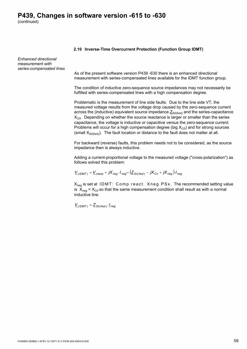
P439, Changes in software version -615 to -630 (continued)
P439/EN AD/Bk5 // AFSV.12.10371 D /// P439-305-409/410-630 59
2.10 Inverse-Time Overcurrent Protection (Function Group IDMT)
Enhanced directional measurement with series-compensated lines
As of the present software version P439 -630 there is an enhanced directional measurement with series-compensated lines available for the IDMT function group.
The condition of inductive zero-sequence source impedances may not necessarily be fulfilled with series-compensated lines with a high compensation degree.
Problematic is the measurement of line side faults: Due to the line side VT, the measured voltage results from the voltage drop caused by the zero-sequence current across the (inductive) equivalent source impedance ZS0(fwd) and the series-capacitance XC0. Depending on whether the source reactance is larger or smaller than the series capacitance, the voltage is inductive or capacitive versus the zero-sequence current. Problems will occur for a high compensation degree (big XC0) and for strong sources (small XS0(fwd)). The fault location or distance to the fault does not matter at all.
For backward (reverse) faults, this problem needs not to be considered, as the source impedance then is always inductive.
Adding a current-proportional voltage to the measured voltage ("cross-polarization") as follows solved this problem:
( ) negnegC)fwd(Snegnegmeas)IDMT( IjXjXZIjXVV ⋅+−=⋅+= 00
Xneg is set at I D M T : C o m p . r e a c t . X n e g P S x . The recommended setting value is Xneg = XC0 so that the same measurement condition shall result as with a normal inductive line.
neg)fwd(S)IDMT( IZV ⋅= 0
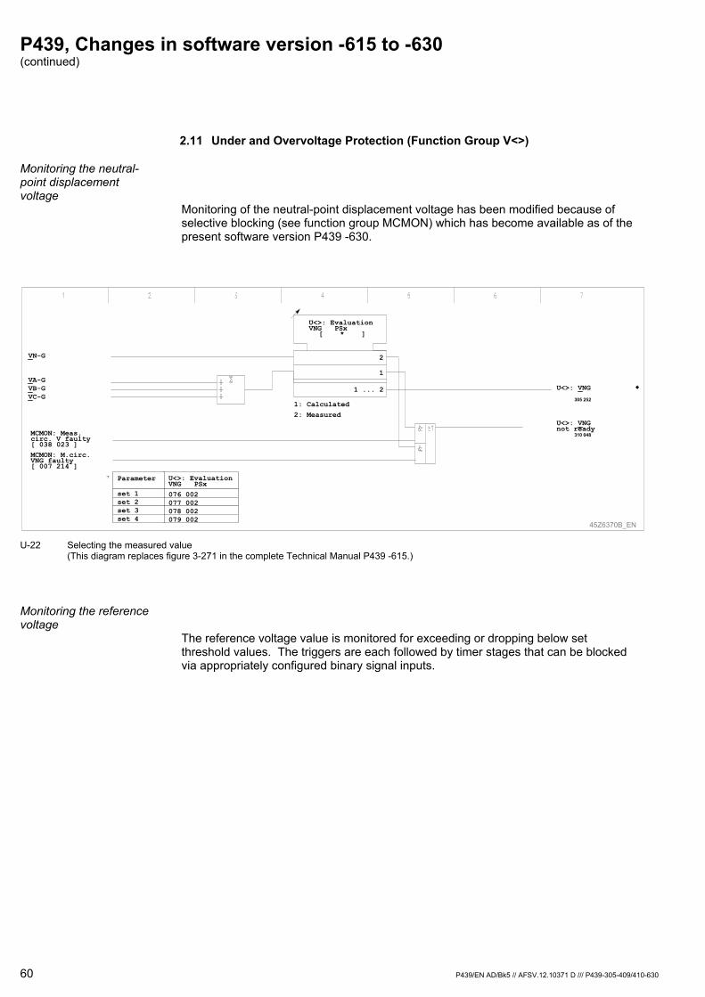
P439, Changes in software version -615 to -630 (continued)
60 P439/EN AD/Bk5 // AFSV.12.10371 D /// P439-305-409/410-630
2.11 Under and Overvoltage Protection (Function Group V<>)
Monitoring the neutral-point displacement voltage
Monitoring of the neutral-point displacement voltage has been modified because of selective blocking (see function group MCMON) which has become available as of the present software version P439 -630.
U<>: EvaluationVNG PSx
[ * ]
45Z6370B_EN
U<>: EvaluationVNG PSx076 002077 002078 002079 002
Parameter
set 1set 2set 3set 4
VA-GVB-GVC-G
VN-G
1
2
1: Calculated2: Measured
1 ... 2 U<>: VNG
305 252
U<>: VNGnot ready
310 048
MCMON: M.circ.VNG faulty[ 007 214 ]
MCMON: Meas.circ. V faulty[ 038 023 ]
U-22 Selecting the measured value
(This diagram replaces figure 3-271 in the complete Technical Manual P439 -615.)
Monitoring the reference voltage
The reference voltage value is monitored for exceeding or dropping below set threshold values. The triggers are each followed by timer stages that can be blocked via appropriately configured binary signal inputs.
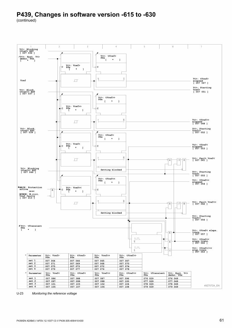
P439, Changes in software version -615 to -630 (continued)
P439/EN AD/Bk5 // AFSV.12.10371 D /// P439-305-409/410-630 61
V<>: Vref>PSx[ * ]
V<>: tVref>PSx
[ * ]
V<>: Vref>>PSx[ * ]
V<>: tVref>>PSx
[ * ]
V<>: Vref<PSx[ * ]
V<>: tVref<PSx
[ * ]
V<>: Vref<<PSx[ * ]
V<>: tVref<<PSx
[ * ]
V<>: BlockingtVref> EXT[ 007 036 ]
V<>: Block.tVref>> EXT[ 007 037 ]
V<>: Block.tVref< EXT[ 007 039 ]
V<>: BlockingtVref<< EXT[ 007 046 ]
V<>: tVref< elaps.trans.[ 007 057 ]
V<>: tVref<<elaps.trans.[ 007 060 ]
V<>: tVref</<<elap.trans[ 007 063 ]
V<>: StartingVref<<[ 007 056 ]
V<>: Fault Vref<<[ 007 062 ]
V<>: tVref<<elapsed[ 007 054 ]
V<>: StartingVref<[ 007 055 ]
V<>: Fault Vref<[ 007 061 ]
V<>: tVref<elapsed[ 007 053 ]
V<>: StartingVref>>[ 007 052 ]
V<>: tVref>>elapsed[ 007 048 ]
V<>: StartingVref>[ 007 051 ]
V<>: tVref>elapsed[ 007 047 ]
Vref
49Z7072A_EN
V<>: tTransientPSx[ * ]
V<>: tVref>PSx007 066007 069007 073007 077
V<>: Vref>PSx007 064007 071007 075007 079
Parameter
set 1set 2set 3set 4
V<>: tVref<PSx007 088007 099007 103007 107
V<>: Vref<PSx007 086007 097007 101007 105
Parameter
set 1set 2set 3set 4
V<>: tVref>>PSx007 067007 070007 074007 078
V<>: Vref>>PSx007 065007 068007 072007 076
V<>: tVref<<PSx007 096007 100007 104007 108
V<>: Vref<<PSx007 087007 098007 102007 106
V<>: Hyst. V<>deduc. PSx076 049077 049078 049079 049
V<>: tTransientPSx076 029077 029078 029079 029
V<>: Hyst. V<>deduc. PSx[ * ]
Setting blocked
Setting blocked
CC
CC
CC
CCMAIN: Protectionactive
306 001
MCMON: M.circ.Vref faulty[ 007 213 ]
U-23 Monitoring the reference voltage
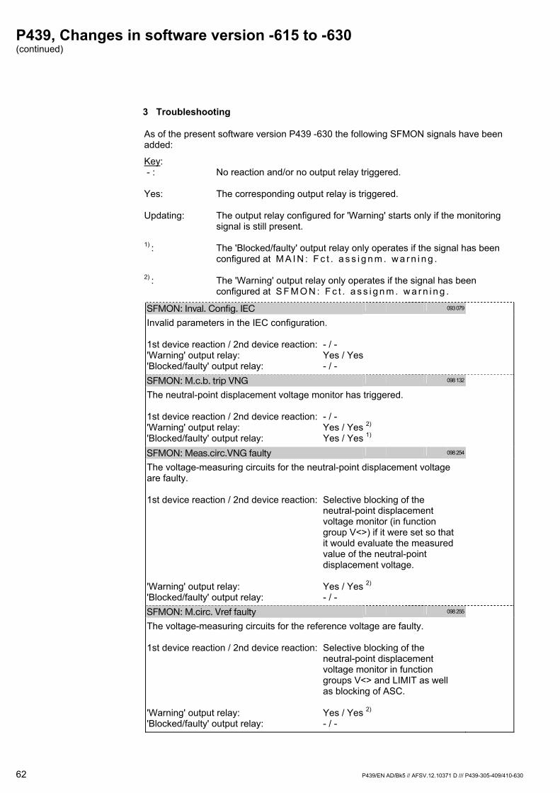
P439, Changes in software version -615 to -630 (continued)
62 P439/EN AD/Bk5 // AFSV.12.10371 D /// P439-305-409/410-630
3 Troubleshooting
As of the present software version P439 -630 the following SFMON signals have been added:
Key: - : No reaction and/or no output relay triggered. Yes: The corresponding output relay is triggered. Updating: The output relay configured for 'Warning' starts only if the monitoring signal is still present. 1) : The 'Blocked/faulty' output relay only operates if the signal has been configured at M A I N : F c t . a s s i g n m . w a r n i n g . 2) : The 'Warning' output relay only operates if the signal has been configured at S F M O N : F c t . a s s i g n m . w a r n i n g .
SFMON: Inval. Config. IEC 093 079
Invalid parameters in the IEC configuration. 1st device reaction / 2nd device reaction: - / - 'Warning' output relay: Yes / Yes 'Blocked/faulty' output relay: - / -
SFMON: M.c.b. trip VNG 098 132
The neutral-point displacement voltage monitor has triggered. 1st device reaction / 2nd device reaction: - / - 'Warning' output relay: Yes / Yes 2) 'Blocked/faulty' output relay: Yes / Yes 1)
SFMON: Meas.circ.VNG faulty 098 254
The voltage-measuring circuits for the neutral-point displacement voltage are faulty. 1st device reaction / 2nd device reaction: Selective blocking of the neutral-point displacement voltage monitor (in function group V<>) if it were set so that it would evaluate the measured value of the neutral-point displacement voltage. 'Warning' output relay: Yes / Yes 2) 'Blocked/faulty' output relay: - / -
SFMON: M.circ. Vref faulty 098 255
The voltage-measuring circuits for the reference voltage are faulty. 1st device reaction / 2nd device reaction: Selective blocking of the neutral-point displacement voltage monitor in function groups V<> and LIMIT as well as blocking of ASC. 'Warning' output relay: Yes / Yes 2) 'Blocked/faulty' output relay: - / -

P439/EN AD/Bk5 // AFSV.12.10371 D /// P439-305-409/410-630 63
Schneider Electric 35 rue Joseph Monier 92506 Rueil-Malmaison FRANCE
Phone: +33 (0) 1 41 29 70 00 Fax: +33 (0) 1 41 29 71 00 www.schneider-electric.com Publishing: Schneider ElectricPublication: P439/EN AD/Ck5 // AFSV.12.10372 D /// P439-305-409/410-630 06/2011
Customer Care Centre
http://www.schneider-electric.com/CCC
©
201
1 S
chne
ider
Ele
ctric
. All
right
s re
serv
ed.

MiCOM P439
Distance Protection and Control Unit
P439/EN AD/Am5 (AFSV.12.10990 D)
Version P439 -305 -409/410 -630 ⇒ P439 -305 -409/410 -631
Upgrade Documentation


P439, Changes in software version -630 to -631
In the new versions of the Distance Protection and Control Unit MiCOM P439, several enhanced features and changes on existing features have been included. These are described with reference to the documentation listed below:
References Version Documentation Released
10.03.2008 P439-304-407/408-615 Technical Manual P439/EN M/Cd4 (AFSV.12.10190 D) Upgrade Documentation P439/EN AD/Ak5 (AFSV.12.10370 D)
10.09.2009 P439-305-409/410-630
Note:
The software versions P439-61x constitute a product line that was developed independent to versions P439-63x. (The main difference is that the device versions with software versions P439-63x feature the “phase 2” implementation of function group IEC whereas software versions P439-61x continue with the “phase 1” implementation.)
P439/EN AD/Am5 // AFSV.12.10990 D /// P439-305-409/410-631 3

P439, Changes in software version -630 to -631 (continued)
1 Overview
Version Changes
Hardware No change P439-305-409/410-631
No change Diagram
Release: 07.01.2011 Software The following menu point has been removed:
P C : N a m e o f m a n u f a c t u r e r (003 183) Note: Compatibility even with older versions of the operating program continues to be guaranteed.
PC
In order to guarantee full compatibility with PACiS the neutral-point displacement voltage (calculated and measured) as well as the residual current (calculated and measured) were assigned to the node MMXU so that the node MSQI now includes only the positive-sequence and negative-sequence values.
IEC
The data point C O M M 1 : - 1 0 3 p r o t . v a r i a n t (003 178) may now be used to select between the 103 protocol variants Private and Compatible. The protocol variant Compatible corresponds to the VDEW implementation. Note: As before this setting is hidden unless an IEC 60870-5 protocol is enabled.
COMM1
The data point C O M M 1 : M O D B U S p r o t . v a r i a n t (003 214) may now be used to select between the MODBUS protocol variants Private and Compatible. The protocol variant Compatible corresponds to the MODBUS implementation in the MiCOM Px20 and Px40 protection devices. The protocol variant Private corresponds to the first implementation of the MODBUS protocol. Note: As before this setting is hidden unless the MODBUS protocol is enabled.
COMM1
The menu points C O M M 1 : N a m e o f m a n u f a c t u r e r (003 161) and C O M M 2 : N a m e o f m a n u f a c t u r e r (103 161) can no longer be set by using a selection list but, for reasons of compatibility, they may now be defined as free text. The default is SE but, in individual cases, it may become necessary to enter texts differing from the default. Notes: These parameters can only be set using the operating program and it is not possible to set them locally using the integrated local control panel (HMI). The maximum text length is 8 characters and designations exceeding this will be truncated. The parameter C O M M 1 : N a m e o f m a n u f a c t u r e r is hidden unless an IEC 60870-5 protocol is enabled.
COMM1, COMM2
The internal range for the primary measured power values was extended from 1000 MW, 1000 MVAr and 1300 MVA to 3200 MW, 3200 MVAr and 3200 MVA, respectively. This applies to the following data points: (005 025) M A I N : A p p a r . p o w e r S p r i m . (004 050) M A I N : A c t i v e p o w e r P p r i m . (004 052) M A I N : R e a c . p o w e r Q p r i m .
MAIN
4 P439/EN AD/Am5 // AFSV.12.10990 D /// P439-305-409/410-631
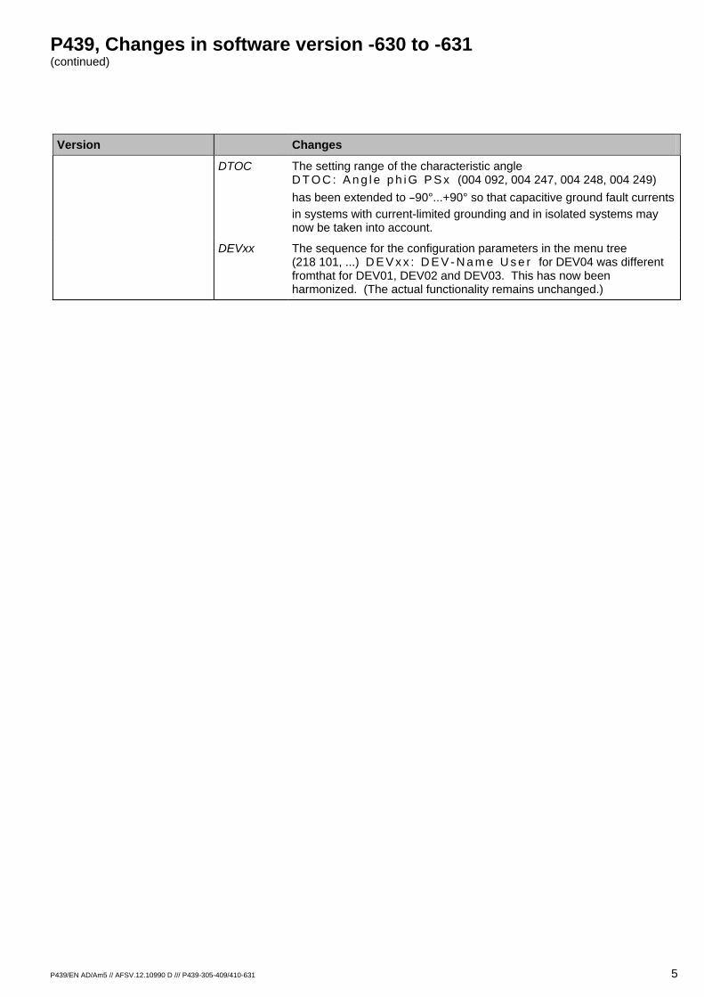
P439, Changes in software version -630 to -631 (continued)
P439/EN AD/Am5 // AFSV.12.10990 D /// P439-305-409/410-631 5
Version Changes DTOC The setting range of the characteristic angle
D T O C : A n g l e p h i G P S x (004 092, 004 247, 004 248, 004 249) has been extended to -90°...+90° so that capacitive ground fault currents in systems with current-limited grounding and in isolated systems may now be taken into account.
DEVxx The sequence for the configuration parameters in the menu tree (218 101, ...) D E V x x : D E V - N a m e U s e r for DEV04 was different fromthat for DEV01, DEV02 and DEV03. This has now been harmonized. (The actual functionality remains unchanged.)
Customer Care Centre
http://www.schneider-electric.com/CCC
© 2
011
Sch
neid
er E
lect
ric. A
ll rig
hts
rese
rved
.
Schneider Electric 35 rue Joseph Monier 92506 Rueil-Malmaison FRANCE
Phone: +33 (0) 1 41 29 70 00 Fax: +33 (0) 1 41 29 71 00 www.schneider-electric.com Publishing: Schneider ElectricPublication: P439/EN AD/Am5 // AFSV.12.10990 D /// P439-305-409/410-631 06/2011


Customer Care Centre
http://www.schneider-electric.com/CCC
©
201
1 S
chne
ider
Ele
ctric
. All
right
s re
serv
ed.
Schneider Electric 35 rue Joseph Monier 92506 Rueil-Malmaison FRANCE
Phone: +33 (0) 1 41 29 70 00 Fax: +33 (0) 1 41 29 71 00 www.schneider-electric.com Publishing: Schneider ElectricPublication: P439/EN M/Am5 Version: -615 -618 -630 -631 Vol. 2 06/2011