miata installation and setup instructions for hydra ... flyin ' miata tuningflyinmiata.com...
TRANSCRIPT
1
[email protected]' Miata970.464.5600
Rev 7.3
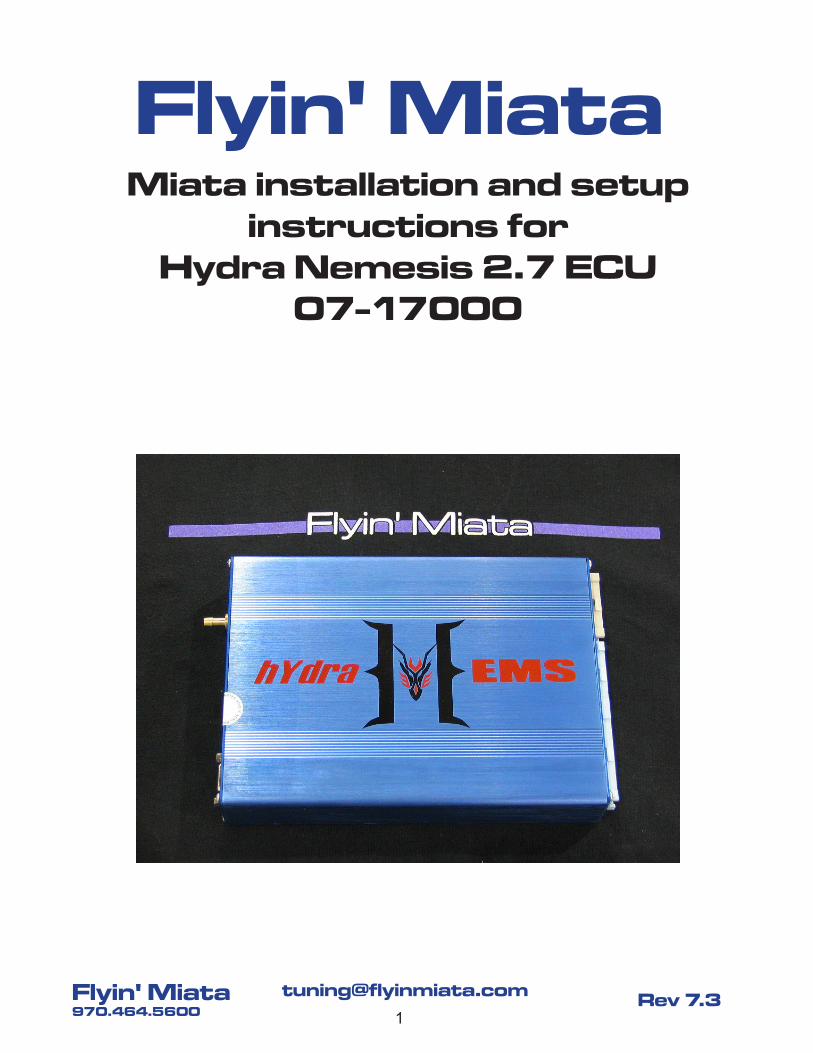
Miata installation and setup instructions for
Hydra Nemesis 2.7 ECU07-17000
Flyin' Miata
2
[email protected]' Miata970.464.5600
Rev 7.3
ContentsBasic Info About the Hydra Nemesis Engine Management System ......3Installing the Hydra Nemesis Engine Control Unit.................................4Setting up the ECU ..............................................................................12Initial ECU Tuning ................................................................................15Fuel "Auto" Tuning ...............................................................................19Tuning Your Timing ..............................................................................19Closed Loop Alternator Control (99-05) ...............................................21Variable Intake Valve Timing (01-05, except MSM) .............................22Electronic Boost Control for turbo cars ................................................23Other Capabilities ................................................................................24Appendix A- Emissions ........................................................................24
WARNINGS!
Modifying your vehicle can be very rewarding, but it also has the potential of leading to finan-cial and emotional distress. The Hydra Nemesis ECU is no different- standalone engine man-agement tuning is serious business! If you are not qualified to tune your vehicle's computer, PLEASE seek out the assistance of a professional. The tech staff at FM will be happy to help as much as we can with installation and tuning via phone and e-mail, but there are still a num-ber of things that have to be understood & calibrated in person by you or a qualified profes-sional. FM's base maps are good, but it is impossible to account for every variable there is. With that in mind, neither Flyin' Miata nor Hydra EMS will be held responsible for the results of bad tuning or bad luck on the part of the end user. Also, when street tuning, use either a co-pilot or the datalog feature in your laptop in order to make safe tuning changes. Please do not drive and tune at the same time! We of course recommend dyno tuning for the best and safest results.
The Hydra ECU will not return OBD-II codes and is not CARB legal. The end user is responsible for determining if this system is legal for use on public roads in their state. By installing the Hydra EMS in your car you acknowledge and understand the aforemen-tioned guidelines & recommendations.
3
[email protected]' Miata970.464.5600
Rev 7.3
Basic Info About the Hydra Nemesis Engine Management System
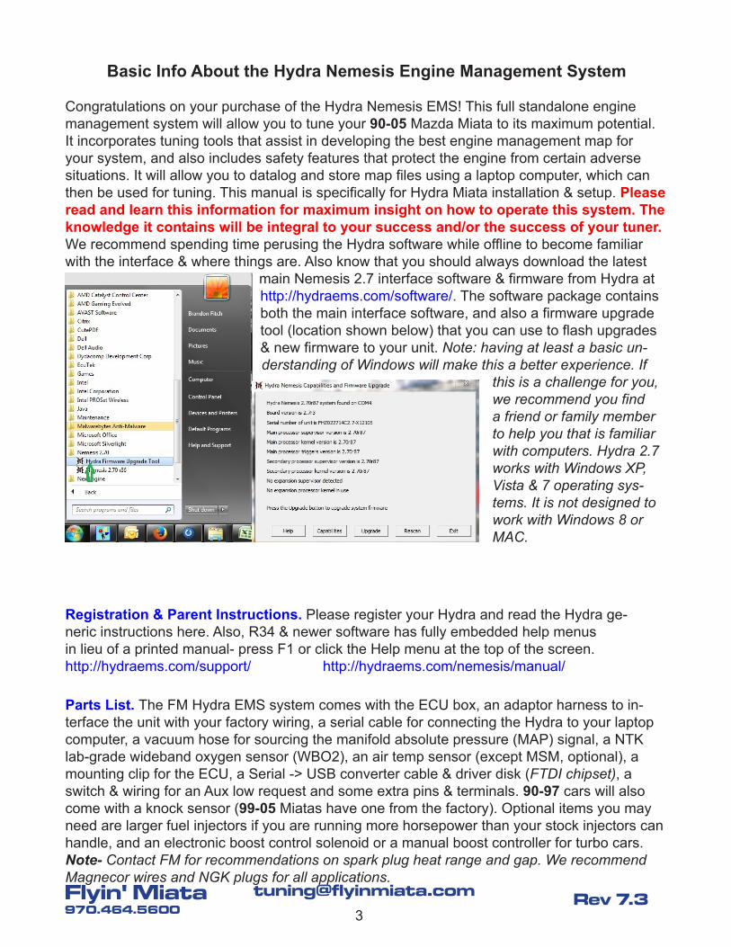
Congratulations on your purchase of the Hydra Nemesis EMS! This full standalone engine management system will allow you to tune your 90-05 Mazda Miata to its maximum potential. It incorporates tuning tools that assist in developing the best engine management map for your system, and also includes safety features that protect the engine from certain adverse situations. It will allow you to datalog and store map files using a laptop computer, which can then be used for tuning. This manual is specifically for Hydra Miata installation & setup. Please read and learn this information for maximum insight on how to operate this system. The knowledge it contains will be integral to your success and/or the success of your tuner. We recommend spending time perusing the Hydra software while offline to become familiar with the interface & where things are. Also know that you should always download the latest
main Nemesis 2.7 interface software & firmware from Hydra at http://hydraems.com/software/. The software package contains both the main interface software, and also a firmware upgrade tool (location shown below) that you can use to flash upgrades & new firmware to your unit. Note: having at least a basic un-derstanding of Windows will make this a better experience. If
this is a challenge for you, we recommend you find a friend or family member to help you that is familiar with computers. Hydra 2.7 works with Windows XP, Vista & 7 operating sys-tems. It is not designed to work with Windows 8 or MAC.
Registration & Parent Instructions. Please register your Hydra and read the Hydra ge-neric instructions here. Also, R34 & newer software has fully embedded help menus in lieu of a printed manual- press F1 or click the Help menu at the top of the screen. http://hydraems.com/support/ http://hydraems.com/nemesis/manual/
Parts List. The FM Hydra EMS system comes with the ECU box, an adaptor harness to in-terface the unit with your factory wiring, a serial cable for connecting the Hydra to your laptop computer, a vacuum hose for sourcing the manifold absolute pressure (MAP) signal, a NTK lab-grade wideband oxygen sensor (WBO2), an air temp sensor (except MSM, optional), a mounting clip for the ECU, a Serial -> USB converter cable & driver disk (FTDI chipset), a switch & wiring for an Aux low request and some extra pins & terminals. 90-97 cars will also come with a knock sensor (99-05 Miatas have one from the factory). Optional items you may need are larger fuel injectors if you are running more horsepower than your stock injectors can handle, and an electronic boost control solenoid or a manual boost controller for turbo cars. Note- Contact FM for recommendations on spark plug heat range and gap. We recommend Magnecor wires and NGK plugs for all applications.
4
[email protected]' Miata970.464.5600
Rev 7.3
Installing the Hydra Nemesis Engine Control Unit
Location. Start by disconnecting the negative battery terminal. Then, locate the stock ECU. On U.S. spec vehicles it is: under the dash by the steering column on 99-05 cars; behind the passenger seat on 94-97 cars; and under the passenger's kick panel on 90-93 cars. Unplug the factory harness connectors. For 90-97 cars the Hydra will sit in the location that the facto-ry ECU occupied using the supplied clip, so you'll need to remove the stock ECU. Note- For 90-93 cars with ABS you'll have to do what you need to do in order to fit both the ABS module & the Hydra under the kick panel- it's a tight fit. We recommend removing that padding against the floor so the computer can breathe better & is less likely to overheat. For 99-05 cars take the adaptor harness and run it under the dash (above the transmission tunnel) such that the single connector end is on the driver's side and the three connector end is on the passenger's side. Then you'll mount the Hydra behind the glove box with the supplied bracket: on 99-00 cars the bracket mounts to a 6mm stud at the bottom, while on 01-05 cars it mounts to a 6mm stud at the top. To remove the glove box on the 99-05, open it and pull the right side towards the rear of the car. Once the right side pops out the left side will slide out. Note- For 01-05 cars with the keyless entry module, or 99-00 cars with the ABS module, you will need to stash the module behind the ECU in the blower motor area.
Next (for all cars) plug the stock harness ends into the adaptor harness plug. Attach the seri-al cable and run it out somewhere where it can be stashed normally but accessed for tuning. Leave the 3 plug side of the adaptor harness be for now- you'll have to pin in the WBO2 wires which will be described later. Attach the MAP sensor hose to the barb on the Hydra and run it out through the firewall to an appropriate signal source (vacuum nipple) on the intake manifold plenum. The source must be between the throttle body and head when looking at the direction of airflow- this way the Hydra will see both vacuum and boost. This means no check valves inline! In fact, we don't recommend sharing this MAP hose with anything other than a boost gauge. Note- This is the most important hose on the car! A failure, a leak, or a pinch here can cause poor running and possibly major engine damage. Please maintain this hose accordingly! Also, on 99-05 intake manifolds there's at least one nipple and also a check valve that does not see vacuum & boost, so be sure to verify that the Hydra MAP sensor sees both vacuum & boost when you first drive the car. (In the software "Dashboard" make sure that the Load values are appropriate for your throttle inputs.) If you download the turbo kit instruc-tions from our website we have photos of recommended places to pick up the vacuum source on the various year cars.
Extra Grounds. The 2.7's extra processing power has led us to recommend bolstering the ECU ground wires in some applications where the stock ground footprint is not robust enough to keep up with the ground demand. Your harness may have the following flying-lead ground wires that you'll need to crimp a ring terminal to & bolt to a chassis ground point. If it does not you can add them by building a wire. 90-93: BC03. 99-05 & MSM: BC03 & GB12. Contact FM if you would like a copy of your wiring harness diagram.
5
[email protected]' Miata970.464.5600
Rev 7.3
Note: If you need to crimp on a terminal pin this requires a special terminal crimping tool. For-tunately we know a fellow Hydra owner who sells them. TOOL-01002 will be the cheapest one available, TOOL-01015 is better but much more costly.
http://www.bmotorsports.com/shop/product_info.php/products_id/364 http://www.bmotorsports.com/shop/product_info.php/products_id/2268
MAF Removal. Because the Hydra uses an internal MAP sensor you can eliminate the factory mass air flow sensor on 94-05 cars (MAF) or the air flow meter on 90-93 cars (AFM) which im-poses a restriction on your intake system. This sensor is located at the outlet of the factory air cleaner assembly. Remove this sensor if you want to increase the flow potential of your intake. If the removal of this unit creates a void that needs to be filled in your intake system, you will need to fabricate or purchase a pipe to take its place. Our FM2 turbo kits include a stainless steel delete pipe for the 94-05 MAF. The section of harness that went to the MAF can be tied back out of the way- it is no longer used. You will want to tape the end up to prevent a short since at least one wire is hot.
Upgrading from a Piggyback (optional). If you are upgrading to the Hydra from some other brand of engine management, you will first need to remove everything associated with that system and return the car's electronics in effect to stock. This will make the Hydra installation much more straightforward. You can do this by applying the install instructions for the old unit in reverse.
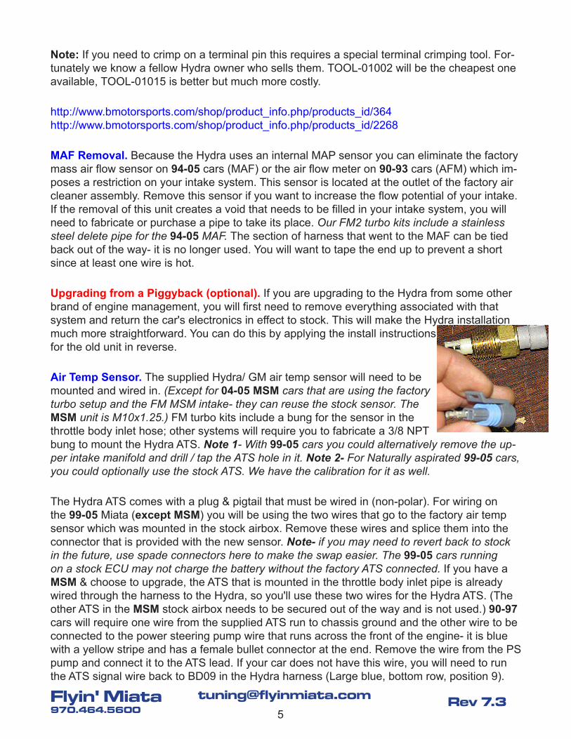
Air Temp Sensor. The supplied Hydra/ GM air temp sensor will need to be mounted and wired in. (Except for 04-05 MSM cars that are using the factory turbo setup and the FM MSM intake- they can reuse the stock sensor. The MSM unit is M10x1.25.) FM turbo kits include a bung for the sensor in the throttle body inlet hose; other systems will require you to fabricate a 3/8 NPT bung to mount the Hydra ATS. Note 1- With 99-05 cars you could alternatively remove the up-per intake manifold and drill / tap the ATS hole in it. Note 2- For Naturally aspirated 99-05 cars, you could optionally use the stock ATS. We have the calibration for it as well.
The Hydra ATS comes with a plug & pigtail that must be wired in (non-polar). For wiring on the 99-05 Miata (except MSM) you will be using the two wires that go to the factory air temp sensor which was mounted in the stock airbox. Remove these wires and splice them into the connector that is provided with the new sensor. Note- if you may need to revert back to stock in the future, use spade connectors here to make the swap easier. The 99-05 cars running on a stock ECU may not charge the battery without the factory ATS connected. If you have a MSM & choose to upgrade, the ATS that is mounted in the throttle body inlet pipe is already wired through the harness to the Hydra, so you'll use these two wires for the Hydra ATS. (The other ATS in the MSM stock airbox needs to be secured out of the way and is not used.) 90-97 cars will require one wire from the supplied ATS run to chassis ground and the other wire to be connected to the power steering pump wire that runs across the front of the engine- it is blue with a yellow stripe and has a female bullet connector at the end. Remove the wire from the PS pump and connect it to the ATS lead. If your car does not have this wire, you will need to run the ATS signal wire back to BD09 in the Hydra harness (Large blue, bottom row, position 9).
6
[email protected]' Miata970.464.5600
Rev 7.3
Fuel Injectors (optional). The factory fuel injectors will support up to around 170-200 rwhp on 99-05 cars and around 150-170 rwhp on 90-97 cars, give or take, based on octane, induction type and tuning. The Hydra can control both high impedance (saturated) and low impedance (peak and hold) injectors with a change to the table at 2D Engine Calibration -> Injector Re-sponse. This injector dead-time compensation is unique to different types of injector, and will affect starting, idle and high vacuum cruising fuel values. FM will program the base map for your injectors so it is important that we know what you are using. We will have the best cali-brations for the injectors we stock. Contact us if you have questions on what injector will best suit your needs- we offer many different types. One other thing to consider is that if you plan on running E85 you'll need injectors that are ~50% larger for the same HP level.
To install the injectors on a 99-05 Miata you will need to remove the upper portion of your intake manifold (including the throttle body) and your fuel rail. For the 90-97 Miatas, you will just need to remove the fuel rail and the hoses/ solenoids that are in the way. Some injectors are plug-in, some come with an adaptor harness. (BTW, solenoids & injectors are non-polar.) Note- After installing fuel injectors make sure to check for fuel leaks immediately after start-ing the car for the first time! Remember to use a light coating of oil on the upper O-ring before pushing the injector into the rail to avoid a pinch. Also, cleaning out the lower seat cup can pre-vent vacuum leaks on a fresh install. Make sure the lower seat rubber is tight enough against the injector when installed to prevent vacuum leaks. Be careful not to drop any debris into the engine through the holes while they are exposed!
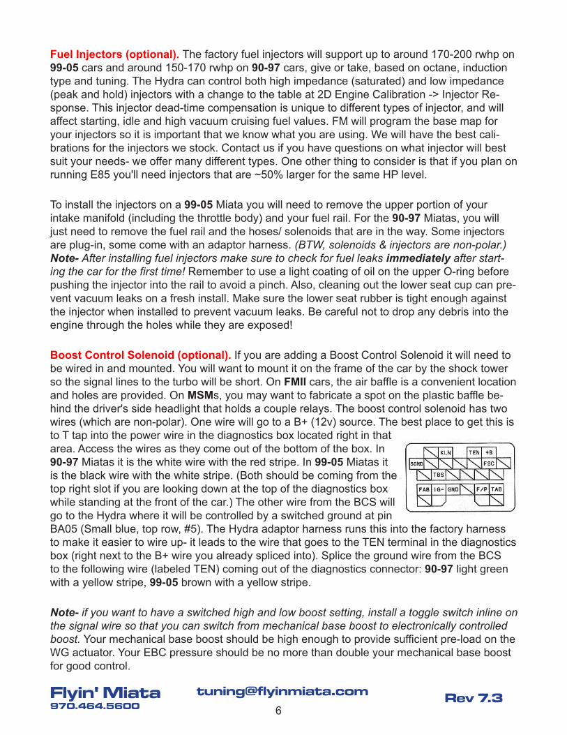
Boost Control Solenoid (optional). If you are adding a Boost Control Solenoid it will need to be wired in and mounted. You will want to mount it on the frame of the car by the shock tower so the signal lines to the turbo will be short. On FMII cars, the air baffle is a convenient location and holes are provided. On MSMs, you may want to fabricate a spot on the plastic baffle be-hind the driver's side headlight that holds a couple relays. The boost control solenoid has two wires (which are non-polar). One wire will go to a B+ (12v) source. The best place to get this is to T tap into the power wire in the diagnostics box located right in that area. Access the wires as they come out of the bottom of the box. In 90-97 Miatas it is the white wire with the red stripe. In 99-05 Miatas it is the black wire with the white stripe. (Both should be coming from the top right slot if you are looking down at the top of the diagnostics box while standing at the front of the car.) The other wire from the BCS will go to the Hydra where it will be controlled by a switched ground at pin BA05 (Small blue, top row, #5). The Hydra adaptor harness runs this into the factory harness to make it easier to wire up- it leads to the wire that goes to the TEN terminal in the diagnostics box (right next to the B+ wire you already spliced into). Splice the ground wire from the BCS to the following wire (labeled TEN) coming out of the diagnostics connector: 90-97 light green with a yellow stripe, 99-05 brown with a yellow stripe.
Note- if you want to have a switched high and low boost setting, install a toggle switch inline on the signal wire so that you can switch from mechanical base boost to electronically controlled boost. Your mechanical base boost should be high enough to provide sufficient pre-load on the WG actuator. Your EBC pressure should be no more than double your mechanical base boost for good control.
7
[email protected]' Miata970.464.5600
Rev 7.3
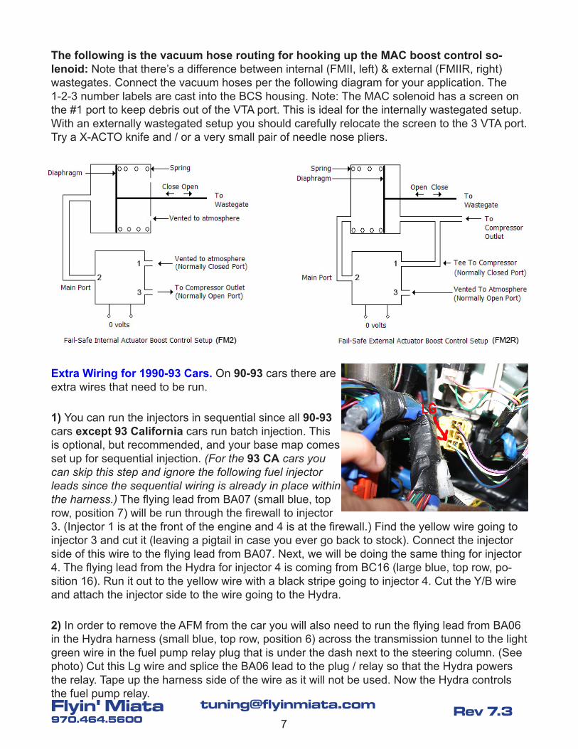
The following is the vacuum hose routing for hooking up the MAC boost control so-lenoid: Note that there’s a difference between internal (FMII, left) & external (FMIIR, right) wastegates. Connect the vacuum hoses per the following diagram for your application. The 1-2-3 number labels are cast into the BCS housing. Note: The MAC solenoid has a screen on the #1 port to keep debris out of the VTA port. This is ideal for the internally wastegated setup. With an externally wastegated setup you should carefully relocate the screen to the 3 VTA port. Try a X-ACTO knife and / or a very small pair of needle nose pliers.
Extra Wiring for 1990-93 Cars. On 90-93 cars there are extra wires that need to be run.
1) You can run the injectors in sequential since all 90-93 cars except 93 California cars run batch injection. This is optional, but recommended, and your base map comes set up for sequential injection. (For the 93 CA cars you can skip this step and ignore the following fuel injector leads since the sequential wiring is already in place within the harness.) The flying lead from BA07 (small blue, top row, position 7) will be run through the firewall to injector 3. (Injector 1 is at the front of the engine and 4 is at the firewall.) Find the yellow wire going to injector 3 and cut it (leaving a pigtail in case you ever go back to stock). Connect the injector side of this wire to the flying lead from BA07. Next, we will be doing the same thing for injector 4. The flying lead from the Hydra for injector 4 is coming from BC16 (large blue, top row, po-sition 16). Run it out to the yellow wire with a black stripe going to injector 4. Cut the Y/B wire and attach the injector side to the wire going to the Hydra.
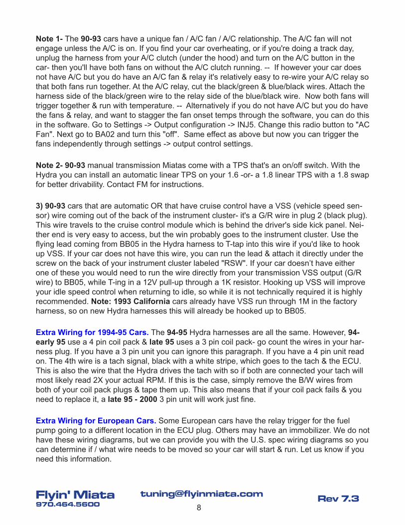
2) In order to remove the AFM from the car you will also need to run the flying lead from BA06 in the Hydra harness (small blue, top row, position 6) across the transmission tunnel to the light green wire in the fuel pump relay plug that is under the dash next to the steering column. (See photo) Cut this Lg wire and splice the BA06 lead to the plug / relay so that the Hydra powers the relay. Tape up the harness side of the wire as it will not be used. Now the Hydra controls the fuel pump relay.
8
[email protected]' Miata970.464.5600
Rev 7.3
Note 1- The 90-93 cars have a unique fan / A/C fan / A/C relationship. The A/C fan will not engage unless the A/C is on. If you find your car overheating, or if you're doing a track day, unplug the harness from your A/C clutch (under the hood) and turn on the A/C button in the car- then you'll have both fans on without the A/C clutch running. -- If however your car does not have A/C but you do have an A/C fan & relay it's relatively easy to re-wire your A/C relay so that both fans run together. At the A/C relay, cut the black/green & blue/black wires. Attach the harness side of the black/green wire to the relay side of the blue/black wire. Now both fans will trigger together & run with temperature. -- Alternatively if you do not have A/C but you do have the fans & relay, and want to stagger the fan onset temps through the software, you can do this in the software. Go to Settings -> Output configuration -> INJ5. Change this radio button to "AC Fan". Next go to BA02 and turn this "off". Same effect as above but now you can trigger the fans independently through settings -> output control settings.
Note 2- 90-93 manual transmission Miatas come with a TPS that's an on/off switch. With the Hydra you can install an automatic linear TPS on your 1.6 -or- a 1.8 linear TPS with a 1.8 swap for better drivability. Contact FM for instructions.
3) 90-93 cars that are automatic OR that have cruise control have a VSS (vehicle speed sen-sor) wire coming out of the back of the instrument cluster- it's a G/R wire in plug 2 (black plug). This wire travels to the cruise control module which is behind the driver's side kick panel. Nei-ther end is very easy to access, but the win probably goes to the instrument cluster. Use the flying lead coming from BB05 in the Hydra harness to T-tap into this wire if you'd like to hook up VSS. If your car does not have this wire, you can run the lead & attach it directly under the screw on the back of your instrument cluster labeled "RSW". If your car doesn’t have either one of these you would need to run the wire directly from your transmission VSS output (G/R wire) to BB05, while T-ing in a 12V pull-up through a 1K resistor. Hooking up VSS will improve your idle speed control when returning to idle, so while it is not technically required it is highly recommended. Note: 1993 California cars already have VSS run through 1M in the factory harness, so on new Hydra harnesses this will already be hooked up to BB05.
Extra Wiring for 1994-95 Cars. The 94-95 Hydra harnesses are all the same. However, 94- early 95 use a 4 pin coil pack & late 95 uses a 3 pin coil pack- go count the wires in your har-ness plug. If you have a 3 pin unit you can ignore this paragraph. If you have a 4 pin unit read on. The 4th wire is a tach signal, black with a white stripe, which goes to the tach & the ECU. This is also the wire that the Hydra drives the tach with so if both are connected your tach will most likely read 2X your actual RPM. If this is the case, simply remove the B/W wires from both of your coil pack plugs & tape them up. This also means that if your coil pack fails & you need to replace it, a late 95 - 2000 3 pin unit will work just fine.
Extra Wiring for European Cars. Some European cars have the relay trigger for the fuel pump going to a different location in the ECU plug. Others may have an immobilizer. We do not have these wiring diagrams, but we can provide you with the U.S. spec wiring diagrams so you can determine if / what wire needs to be moved so your car will start & run. Let us know if you need this information.
9
[email protected]' Miata970.464.5600
Rev 7.3
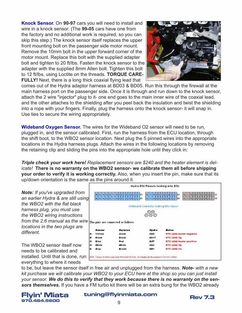
Knock Sensor. On 90-97 cars you will need to install and wire in a knock sensor. (The 99-05 cars have one from the factory and no additional work is required, so you can skip this step.) The knock sensor itself replaces the upper front mounting bolt on the passenger side motor mount. Remove the 10mm bolt in the upper forward corner of the motor mount. Replace this bolt with the supplied adapter bolt and tighten to 20 ft/lbs. Fasten the knock sensor to the adapter with the supplied 8mm Allen bolt. Tighten this bolt to 12 ft/lbs, using Loctite on the threads. TORQUE CARE-FULLY! Next, there is a long thick coaxial flying lead that comes out of the Hydra adaptor harness at BD03 & BD05. Run this through the firewall at the main harness port on the passenger side. Once it is through and run down to the knock sensor, attach the 2 wire "injector" plug to it- one end goes to the main inner wire of the coaxial lead, and the other attaches to the shielding after you peel back the insulation and twist the shielding into a rope with your fingers. Finally, plug the harness onto the knock sensor- it will snap in. Use ties to secure the wiring appropriately.
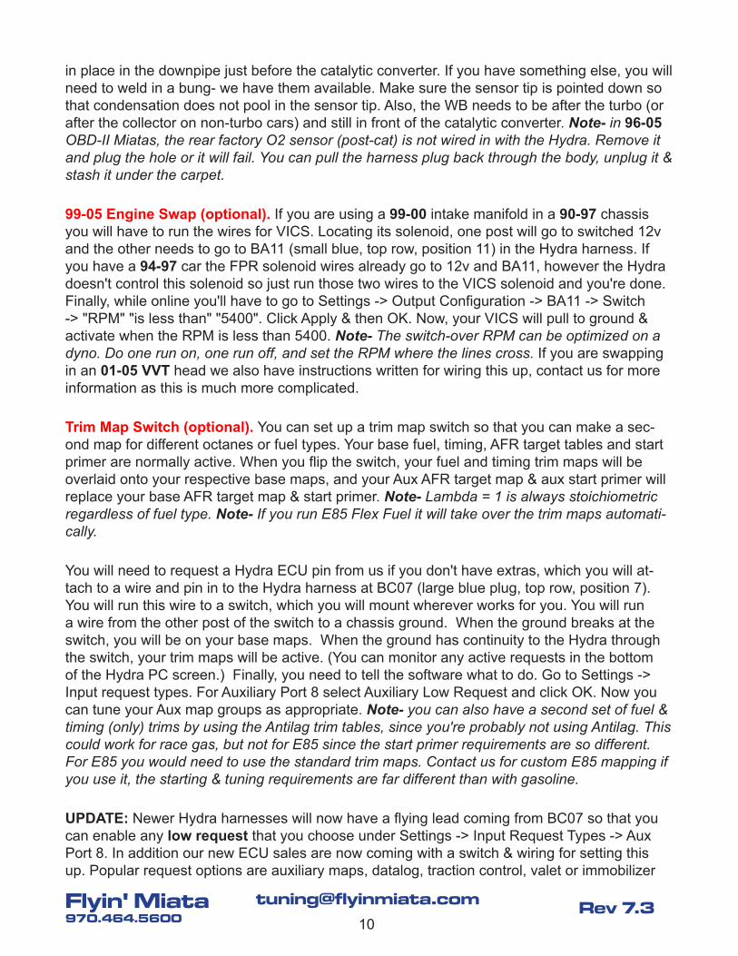
Wideband Oxygen Sensor. The wires for the Wideband O2 sensor will need to be run, plugged in, and the sensor calibrated. First, run the harness from the ECU location, through the shift boot, to the WBO2 sensor location. Next plug the 5 pinned wires into the appropriate locations in the Hydra harness plugs. Attach the wires in the following locations by removing the retaining clip and sliding the pins into the appropriate hole until they click in:
Triple check your work here! Replacement sensors are $240 and the heater element is del-icate! There is no warranty on the WBO2 sensor- we calibrate them all before shipping your order to verify it is working correctly. Also, when you insert the pin, make sure that its up/down orientation is the same as the pins around it.
Note: If you've upgraded from an earlier Hydra & are still using the WBO2 with the flat black harness plug, you must use the WBO2 wiring instructions from the 2.6 manual as the wire locations in the two plugs are different.
The WBO2 sensor itself now needs to be calibrated and installed. Until that is done, run everything to where it needs to be, but leave the sensor itself in free air and unplugged from the harness. Note- with a new kit purchase we will calibrate your WBO2 to your ECU here at the shop so you can just install your sensor. We do this to verify that they work because there is no warranty on the sen-sors themselves. If you have a FM turbo kit there will be an extra bung for the WBO2 already
10
[email protected]' Miata970.464.5600
Rev 7.3
in place in the downpipe just before the catalytic converter. If you have something else, you will need to weld in a bung- we have them available. Make sure the sensor tip is pointed down so that condensation does not pool in the sensor tip. Also, the WB needs to be after the turbo (or after the collector on non-turbo cars) and still in front of the catalytic converter. Note- in 96-05 OBD-II Miatas, the rear factory O2 sensor (post-cat) is not wired in with the Hydra. Remove it and plug the hole or it will fail. You can pull the harness plug back through the body, unplug it & stash it under the carpet.
99-05 Engine Swap (optional). If you are using a 99-00 intake manifold in a 90-97 chassis you will have to run the wires for VICS. Locating its solenoid, one post will go to switched 12v and the other needs to go to BA11 (small blue, top row, position 11) in the Hydra harness. If you have a 94-97 car the FPR solenoid wires already go to 12v and BA11, however the Hydra doesn't control this solenoid so just run those two wires to the VICS solenoid and you're done. Finally, while online you'll have to go to Settings -> Output Configuration -> BA11 -> Switch -> "RPM" "is less than" "5400". Click Apply & then OK. Now, your VICS will pull to ground & activate when the RPM is less than 5400. Note- The switch-over RPM can be optimized on a dyno. Do one run on, one run off, and set the RPM where the lines cross. If you are swapping in an 01-05 VVT head we also have instructions written for wiring this up, contact us for more information as this is much more complicated.
Trim Map Switch (optional). You can set up a trim map switch so that you can make a sec-ond map for different octanes or fuel types. Your base fuel, timing, AFR target tables and start primer are normally active. When you flip the switch, your fuel and timing trim maps will be overlaid onto your respective base maps, and your Aux AFR target map & aux start primer will replace your base AFR target map & start primer. Note- Lambda = 1 is always stoichiometric regardless of fuel type. Note- If you run E85 Flex Fuel it will take over the trim maps automati-cally.
You will need to request a Hydra ECU pin from us if you don't have extras, which you will at-tach to a wire and pin in to the Hydra harness at BC07 (large blue plug, top row, position 7). You will run this wire to a switch, which you will mount wherever works for you. You will run a wire from the other post of the switch to a chassis ground. When the ground breaks at the switch, you will be on your base maps. When the ground has continuity to the Hydra through the switch, your trim maps will be active. (You can monitor any active requests in the bottom of the Hydra PC screen.) Finally, you need to tell the software what to do. Go to Settings -> Input request types. For Auxiliary Port 8 select Auxiliary Low Request and click OK. Now you can tune your Aux map groups as appropriate. Note- you can also have a second set of fuel & timing (only) trims by using the Antilag trim tables, since you're probably not using Antilag. This could work for race gas, but not for E85 since the start primer requirements are so different. For E85 you would need to use the standard trim maps. Contact us for custom E85 mapping if you use it, the starting & tuning requirements are far different than with gasoline.
UPDATE: Newer Hydra harnesses will now have a flying lead coming from BC07 so that you can enable any low request that you choose under Settings -> Input Request Types -> Aux Port 8. In addition our new ECU sales are now coming with a switch & wiring for setting this up. Popular request options are auxiliary maps, datalog, traction control, valet or immobilizer
11
[email protected]' Miata970.464.5600
Rev 7.3
requests. Scroll through the drop-down list & see what's available. To use this you'll need to run the lead through a switch then attach it to chassis ground. When you close the circuit with the switch the request will be active.
LS3 Coil Conversion (optional). The Miata runs its stock coils in batch (waste spark) ignition. While the factory coils are good for most applications, in high boost cars they can run out of steam. An excellent upgrade in these situations is to upgrade to full sequential ignition using the much stronger individual coils from the GM LS3 engine. FM has a complete Big Spark kit including coils, brackets, harness, wires, instructions, etc.- see http://www.flyinmiata.com/ for details.
Flex Fuel (optional). Hydra 2.7 can control a GM flex fuel sensor so that you can set up the mapping to seamlessly handle any ethanol content from E0 to E100. If you live in an area that sells E85 at the pump this gives you the potential for much more power. It is very high octane stuff- we recommend it. A standard FM2 car going from 91 octane to E85 at the same boost level will usually pick up around 25-30 rwhp from the extra timing advance, and for high boost E85 cars octane is no longer an issue. We sell a Big Fuel kit w/ the Flex Fuel sensor included, see http://www.flyinmiata.com/ for details.
36-2 Trigger Wheel. (optional). We offer a 36-2 trigger wheel that can be fitted to your 2.7-powered car for increased timing resolution & smoothness. See http://www.flyinmiata.com/ for details & instructions.
Upgrading from an earlier Hydra.
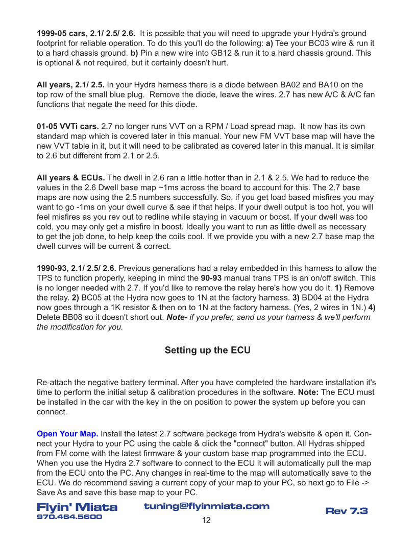
1999-05 cars, 2.1/ 2.5/ 2.6. The tachometer in the NB Miata is more sensitive & we've had to use a different configuration for proper operation w/ 2.7. Without doing this you may lose your tach over ~5K RPM. We've seen a couple 90-97 cars who have also required this mod, but for the most part they do not. If your tach does drop out you will need to follow these instructions to set it up. 1) In the software go to Settings -> Output configuration -> Inj 6. Under the Sim-ple tab Select "Tach". Click OK, and save your new configuration to your PC. 2) At the Hydra harness disconnect the large blue plug that attaches to the Hydra ECU. Remove the plastic combs on both sides to access the terminal pins. 3) Remove the tach wire that is on the top row (thumb tab side), position 12. 4) Re-pin this wire into the same plug, bottom row, position 10. (This is the output for Inj 6.) 5) Procure a 1K (1000) ohm resistor. You'll use the resistor to jumper between the following two wires. This is what we call a "pull-up" resistor. 6) Attach one end of the resistor to the wire you just moved- bottom row #10. 7) Attach the other end of the wire to the wire also on the large blue plug, bottom row, position #1. This is B+. 8) Cover the jumper so it doesn't short out on anything- it is hot! 9) Re-install the combs on the plug and re-assemble everything. 10) Start the car, your tach should work properly. Note- if you prefer, send us your harness & we'll perform the modifica-tion for you.
12
[email protected]' Miata970.464.5600
Rev 7.3
1999-05 cars, 2.1/ 2.5/ 2.6. It is possible that you will need to upgrade your Hydra's ground footprint for reliable operation. To do this you'll do the following: a) Tee your BC03 wire & run it to a hard chassis ground. b) Pin a new wire into GB12 & run it to a hard chassis ground. This is optional & not required, but it certainly doesn't hurt.
All years, 2.1/ 2.5. In your Hydra harness there is a diode between BA02 and BA10 on the top row of the small blue plug. Remove the diode, leave the wires. 2.7 has new A/C & A/C fan functions that negate the need for this diode.
01-05 VVTi cars. 2.7 no longer runs VVT on a RPM / Load spread map. It now has its own standard map which is covered later in this manual. Your new FM VVT base map will have the new VVT table in it, but it will need to be calibrated as covered later in this manual. It is similar to 2.6 but different from 2.1 or 2.5.
All years & ECUs. The dwell in 2.6 ran a little hotter than in 2.1 & 2.5. We had to reduce the values in the 2.6 Dwell base map ~1ms across the board to account for this. The 2.7 base maps are now using the 2.5 numbers successfully. So, if you get load based misfires you may want to go -1ms on your dwell curve & see if that helps. If your dwell output is too hot, you will feel misfires as you rev out to redline while staying in vacuum or boost. If your dwell was too cold, you may only get a misfire in boost. Ideally you want to run as little dwell as necessary to get the job done, to help keep the coils cool. If we provide you with a new 2.7 base map the dwell curves will be current & correct.
1990-93, 2.1/ 2.5/ 2.6. Previous generations had a relay embedded in this harness to allow the TPS to function properly, keeping in mind the 90-93 manual trans TPS is an on/off switch. This is no longer needed with 2.7. If you'd like to remove the relay here's how you do it. 1) Remove the relay. 2) BC05 at the Hydra now goes to 1N at the factory harness. 3) BD04 at the Hydra now goes through a 1K resistor & then on to 1N at the factory harness. (Yes, 2 wires in 1N.) 4) Delete BB08 so it doesn't short out. Note- if you prefer, send us your harness & we'll perform the modification for you.
Setting up the ECU
Re-attach the negative battery terminal. After you have completed the hardware installation it's time to perform the initial setup & calibration procedures in the software. Note: The ECU must be installed in the car with the key in the on position to power the system up before you can connect.
Open Your Map. Install the latest 2.7 software package from Hydra's website & open it. Con-nect your Hydra to your PC using the cable & click the "connect" button. All Hydras shipped from FM come with the latest firmware & your custom base map programmed into the ECU. When you use the Hydra 2.7 software to connect to the ECU it will automatically pull the map from the ECU onto the PC. Any changes in real-time to the map will automatically save to the ECU. We do recommend saving a current copy of your map to your PC, so next go to File -> Save As and save this base map to your PC.
13
[email protected]' Miata970.464.5600
Rev 7.3
Notes- a) The base map programmed into your ECU prior to shipping at FM has settings as appropriate for your car. This should get your car going, and may even be really close to op-timum. However as all cars are a little different, you are in charge of verifying that the fuelling & timing tables are in fact safe for your octane & the type of driving you'll be doing- this is where a professional tuner would be a worthwhile investment. b) When you key on 01-05 cars after installing the Hydra you will get a "blinky key" light. This is the immobilizer function in the factory ECU. It is not an operational issue- you can simply remove the light bulb from the instrument cluster. The Hydra BYPASSES the factory immobilizer. c) If we have emailed you a new base map you can install it into your Hydra by getting connected & going to File -> Open. Follow the prompts that tell you you're about to overwrite the current file, choose the file we sent you, and the software will upload it into your ECU. You can verify the upload by looking at the file name in the top of the screen. d) The 1999-05 setups do not have the battery charge light connected, just FYI.
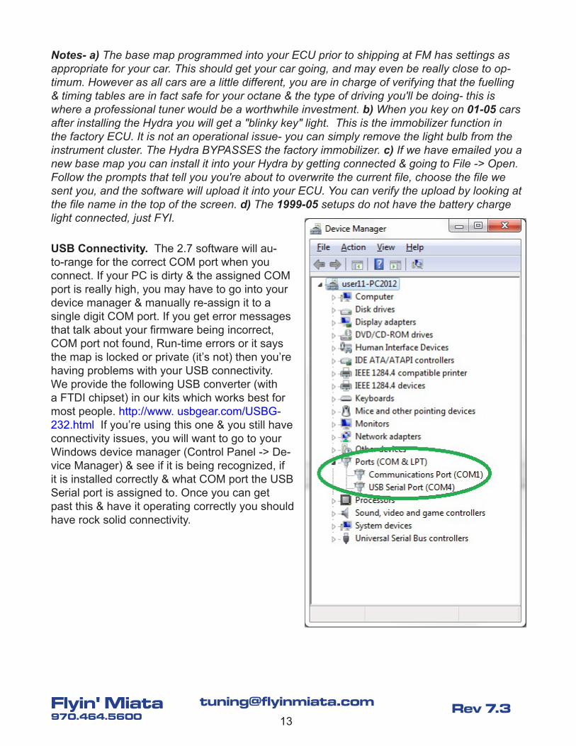
USB Connectivity. The 2.7 software will au-to-range for the correct COM port when you connect. If your PC is dirty & the assigned COM port is really high, you may have to go into your device manager & manually re-assign it to a single digit COM port. If you get error messages that talk about your firmware being incorrect, COM port not found, Run-time errors or it says the map is locked or private (it’s not) then you’re having problems with your USB connectivity. We provide the following USB converter (with a FTDI chipset) in our kits which works best for most people. http://www. usbgear.com/USBG-232.html If you’re using this one & you still have connectivity issues, you will want to go to your Windows device manager (Control Panel -> De-vice Manager) & see if it is being recognized, if it is installed correctly & what COM port the USB Serial port is assigned to. Once you can get past this & have it operating correctly you should have rock solid connectivity.
14
[email protected]' Miata970.464.5600
Rev 7.3
Throttle Position Sensor Calibration. Next, you need to calibrate your Throttle Position Sensor for closed throttle and WOT. Key on but do not start the engine. While connected go to Tools -> Calibrations & follow the prompts. Note- You should re-check the closed throttle cal once the engine bay is heat-soaked. If you notice your closed throttle cal values floating more than a point or two after initial calibration you may need to replace your TPS.
If your ISC is healthy & does not float when it gets hot the current calibration spec is good. If it does float you may improve drivability by manually entering the calibration to account for the float. Go to Tools -> calibrations and move the TPS zero cal slider bar +1 or +2 to achieve the desired results. Do NOT hit the calibrate button if you do it manually- just hit the Done button at the bottom. Reason being if your TPS does float up with heat you may get stuck in open loop ISC control & your idle speed will raise or oscillate. The Hydra will run closed loop ISC only when the TPS = 0 & your RPM is < the value in Decel Fuel Cut Lower Limit.
Note: When you are driving, as the car is rolling up to a stop, it is advisable to clutch in while your RPM is > your (Tuning Maps -> Engine Trimming ->) Decel Fuel Cut Lower Limit value. If you wait till your RPM falls below this value to clutch in, your ISC closed loop control will start working, dragging down the ISC%, and when you finally do clutch in the engine may stall or else droop then recover in a big oscillation pattern.
WBO2 Calibration. While in the Tools -> Calibrations screen you'll also calibrate the wideband O2 sensor if we haven't already. If your battery is not between 12.5-14.5v with the key on you may want to hook a charger up while doing this- Miata batteries are weak, and the WB heater circuit needs a lot of juice to make full temp. However, if the voltage goes over 14.8 the heat-er circuit will shut down & it also won't calibrate properly. Note- new Hydra kits from FM now have your WBO2 calibrated to your ECU before we ship the kit to you. So, if we indicate that this has been done at the shop, you can skip this step & install your WBO2 sensor. Also, these calibrations stay onboard the ECU so write them down in case you ever load in a different map & have to enter them manually- for example if we send you a new base map. They should be written on the box the WBO2 sensor shipped in. You can see the calibration numbers in the software when you're online by clicking on the cal slider bar pointer.
**My Zero cal is _______ My Gradient cal is _______**
First for the UEGO Zero cal you'll leave the WBO2 unplugged. Second for the UEGO Gradient cal you'll plug the sensor in but leave it hanging in free-air. Note- a) When setting Zero cal, the relationship is actually inverse. b) During gradient calibration the sensor will get very hot- so be careful! When these steps are complete you can save your calibrated base map & then re-move the key from the ignition. Install the WBO2 sensor in the exhaust pipe once it has cooled down. Note- as the sensor ages it is a good idea to repeat the free-air calibration procedure. You can easily check to see if it is off- your AFR (WBO2) should read around 14.7 when your O2 (NBO2) left bank is dithering between 0-1 (assuming the front NBO2 is still in the car).
Hint- as you make alterations it is a good idea to save the files to your PC so you have a run-ning log of changes. This way, if a map error occurs you always have a place to go back to. If an * appears at the end of your file name at the top of your screen, there are changes in the ECU that have not been saved to your PC map file.
15
[email protected]' Miata970.464.5600
Rev 7.3
Switching from WBO2 to NBO2. The base map comes set up for the Wideband O2 sensor. (linear 0-5v, 5 wire) We do recommend leaving your factory primary narrowband O2 sensor (non-linear, 0-1v, 1 or 4 wire) installed so you can a) reality check the WBO2 calibration since the NB will only effectively tell you stoichiometric (14.7 for gasoline) or b) switch back to the NB if the WB dies. Also, NBO2s are usually better for stoich & emissions testing. The sensor type can be changed by going to Settings -> AFR target settings -> Left module sensor source. The Miata application only uses the left module.
Note- the only times you would run Open Loop (no O2 sensor feedback at all) are a) if you had a failed O2 sensor causing the car to run poorly, b) if you are dyno tuning and want to see your A/F ratios and injector pulse width straight as they are in the map without any O2 closed loop trim applied, or c) if you have a well tuned track-only race car.
If your car is a track car that spends all its time at full throttle, keep in mind that WBO2s are fairly temperature & pressure sensitive & may lose accuracy (and lifespan) under sustained WOT driving conditions. In this case you may consider confirming your fuel mapping before a track day (or during warm-up) & then racing under open loop.
Initial ECU Tuning
Starting. Once you are confident that everything has been installed correctly & there are no fuel leaks let's try to start the car. Get connected to your laptop & make sure all of your sen-sor inputs are giving correct readings. Make sure there's no magic smoke when you key-on, and check for fuel leaks if you did any work to the fuel system. CTS & ATS should be close to ambient temperature. The MAP sensor should be around 100 kPa at sea level, and lower with altitude. Your TPS & WBO2 calibrations should be done. Take a deep breath & turn the key. Hopefully it fires right up! If not, look at the following. A) Is your battery voltage good? Try jumper cables to a running car. (A jumper box is not always adequate.) B) Is your MAP sensor pulling some vacuum under cranking? If it does start, is the map pulling to somewhere in the 30 kPa range? C) Does your screen show 200-300 RPM during cranking? D) Are your spark plugs fouling out (way too rich) or completely dry (way too lean)? Might need an initial fuelling adjustment. E) Does it feel like it's firing 180° out of time when you crank? (backfires & coughs) Could be a bad cam sensor or something similar.
Here are some analysis tools you may need if the base map doesn't fire right up & run well. A) Go to Tools -> Ignition Advance Trims & Fuel Trims. This shows how all your base tables plus trims are stacking up in real-time. B) Go to Tools -> Trigger test, and run this test during crank-ing. Save it & e-mail it to us for review. We have examples of what the trigger test should look like, we can e-mail them upon request to you if you'd like to make the comparison. C) Check your sensor inputs to make sure their numbers look reasonable. If ANY of your sensor inputs are not working properly this will need to be addressed first. D) Datalogging this issue, or any issue really, is definitely your friend when it comes to troubleshooting. We're happy to review datalogs with you- we need a short log showing the problem & also your current Hydra map file. A screen shot of the software's dashboard during cranking is useful as well. Let us know if you need help choosing which variables to datalog for a given problem.
16
[email protected]' Miata970.464.5600
Rev 7.3
If everything else is good to go you may just need to massage your starting fuel numbers. Pull your plugs after cranking, see if they are dripping or dry, and then alter your cranking fuel table in the appropriate direction to get it within range where the car will start. You need to get it started & warmed up before you can really dial in the fuel numbers, so good enough to run decent is good enough for now. Note- you can select multiple cells by holding down the Shift key while arrowing around, and you can apply math to selected cells by hitting the M/ D/ A/ S/ Enter keys. Standard Windows keystrokes such as Ctrl A, X, C, V also work in your 2D & 3D maps.
Important Note- Once the car is idling smoothly & warming up, make sure your fans are com-ing on at the correct temperature! (Settings -> Output Control Settings) It is important to verify this first so you don't get involved in other things & find out the hard way they didn't come on & the engine overheated.
Side Note- There have been a few cars that have an issue where the AC clutch & AC fan relay chatter when engaged. We’ve been discussing this with Hydra for a while now- while they have not been able to come up with an embedded solution they have come up with a work-around that does solve the problem. Where are these relays you might ask? That’s simple. They’re under the hood. If you turn on the AC fan & a relay starts chattering, that’s it. If you turn on the AC clutch & a relay starts chattering, that’s it. If you turn these things on & no relays are chat-tering then you don’t have the issue & you can forget these paragraphs & move on. That said, here are the work-arounds for solving the issue should you experience it.
AC Clutch work-around. Go to Settings -> Output configuration -> INJ 5. This is your AC clutch output. If its relay is chattering do the following. Click on the PWM tab. Choose an available PWM map that you are not using (most folks are using none), say for example PWM 2 Map. Click its radio button. Under Frequency click 6Hz. Click OK. Next go to Tuning maps -> PWM maps -> 2D PWM Map 2. In the drop down menu click, clear it out & start typing “external AC clutch” & choose it. Under 0 enter 0.0 Under 1 enter 100.0 It should now operate without chat-ter.
AC Fan work-around. Go to Settings -> Output configuration -> BA 02. This is normally your AC fan, although in some cars this may have been swapped with the main fan to GB 06. If its relay is chattering do the following. Click on the PWM tab. Choose an available PWM map that you are not using (most folks are using none), say for example PWM 3 Map. Click its radio but-ton. Under Frequency click 6Hz. Click OK. Next go to Tuning maps -> PWM maps -> 2D PWM Map 3. In the drop down menu click, clear it out & start typing “external AC condensor fan” & choose it. Under 0 enter 0.0 Under 1 enter 100.0 It should now operate without chatter.
Fuel. Start the car and let it idle. Once it is warmed up, if it is obviously rich (spitting) or obvi-ously lean (hunting or stalling) you'll want to make an initial adjustment to the idle fuel areas (Tuning maps -> Base Fuel Table) to get it smoothed out so that you can set the idle speed & base timing. The base map that you were provided is based on cars tuned at FM with similar setups to yours, so it should get you going. You will need to determine if your fuelling is in the ballpark with good drivability so that the auto-tuning (Long Term Trim) can start working. If it is not close enough you will need to set it to open loop & manually set up your base fuel values
17
[email protected]' Miata970.464.5600
Rev 7.3
such that the car is safely drivable before turning closed loop back on & letting auto-tuning do its thing. If you have a custom setup, your mapping should be pretty close assuming that we knew about it before we shipped you the ECU. FWIW, if you're using a fuel injector that we sell you will have a lot less work to do here than if you're using some other injector that we don't have tuned maps for.
Note: in the base maps we have Settings -> AFR target settings -> Closed loop start tem-perature set very low to 0°c for initial installation to help get your idle fuel going right away on a fresh install. Once you have gone through the first process of porting your long term trims back to your base fuel table (after driving through 2-3 tanks of gas) you can set that value back up to a more reasonable floor, say around 70°c.
Idle Speed. Once the car is warned up & idling smoothly you may need to adjust your idle speed. You'll find the controls under Tuning maps -> Base idle speed target, Settings -> Idle Speed Control Settings, and also more advanced mapping under Tuning maps -> Idle speed control. The only mechanical control you have here is the idle air bypass screw in the sheath on the side of your throttle body, and usually this is all you need to set up. We recommend starting out by warming up the car, turning electrical loads off, and rotating the mechanical bypass screw on the side of the throttle body until your ISC% as seen in the Hydra real-time display is in the 30% range. Make sure to do this to calibrate your ISC before thinking about making adjustments to the ISC mapping in the Hydra. For troubleshooting, if rotating that bypass screw in does not reduce a high idle and your ISC % is bottoming out at the value in your (Tuning Maps -> Idle Speed Control ->) Minimum ISC Valve Duty Cycle map the car most likely has a vacuum leak that you'll need to fix before proceeding. Most cars will have this value set in the 15-20% range, but for a car with a lot of idle droop issues you can raise this up to just below the ISC% that the engine normally idles at. (You can also test your ISC motor to see if it's working by unplugging it & seeing if the idle speed changes.) Realistically, the base map settings should be pretty close. Note: The lighter your flywheel, the more challenging idle speed control will be. Superchargers will also have more difficult idle speed control & need to be idled higher. If you find that you do need to fine tune your ISC parameters, start by reading the embedded tutorial & instructions under Help -> Help Topics -> Idle Speed Control Settings.
Note: Here are some initial idle speed control setup troubleshooting tips. These things can cause a high or oscillating idle. 1) As mentioned above, if your Idle Valve % in the dashboard equals the value in your Minimum ISC Valve Duty Cycle map, you may have a vacuum leak that must be fixed. If too much idle air is coming in, either from a leak or from the ISC valve running too far open, the idle can run up into the Tuning maps -> Engine trimming -> Decel fuel cut lower limit map which will cause the idle to swing wildly. 2) If the Idle Valve % is very high, up in the 60% range, It’s possible that your TPS zero calibration is not correct & the ECU thinks your TPS is > 0.0%. Alternatively it could mean that one of your ISC Anticipate values (found under Settings -> Idle speed control settings) is running too high, but that’s unlikely in the base map. 3) If your Idle Valve % is a reasonable value (around 30%) & you’re still getting an idle oscillation, it’s possible that your base idle fuel is simply lean. Manually richen your idle fuel values & see if the idle settles down. 4) For VVT engines- if you haven’t calibrated your VVT base yet (instructions to follow in this document) for now you can unplug the VVT actuator to take it out of the equation for initial idle speed control setup. It can be plugged back in later when you perform the VVT calibration, after achieving a steady idle.
18
[email protected]' Miata970.464.5600
Rev 7.3
Base Timing. Once the car is idling smoothly with a reasonable AFR you'll need to set the base timing- that way what the ECU says for timing advance and what the car is actually doing are the same thing. We have seen some base timing variance when just strapping the Hydra onto a stock car, so this step must be done on 90-97 cars & should be done on 99-05 cars. Setting the base timing will require a timing light. With the car running and at a smooth idle, look at the top of the real-time number display on the right of the home screen. The box la-beled "Advance" is your ignition advance output in degrees, according to the ECU. This value is determined by taking the value from the ignition map and applying to it any ignition trims. (see Tools -> Ignition advance trims) Next, under the hood of the car hook a timing light up to the #1 plug wire and flash the light at the timing marker (around 1-2 o'clock) on the main (crank) pulley. What we want to see is the following: the timing marker on the pulley lines up with the value on the backing plate that corresponds to the displayed ADV reading, in real-time. If it does not you will need to adjust your base timing. Note: if your timing gun has an advance dial, set it to 0.
For example- if the value in ADV is 10, it makes the procedure easy. If your main pulley has one timing notch (90-93), we want this notch to line up with the "10" on the backing plate. If your main pulley has two timing notches (94-05), you want the "driver's right" side notch to line up with the "10" on the backing plate. (Always ignore the "driver's left" side notch.) If the value in ADV is more or less than 10 you will use the idea behind the procedure in the last sentence while making sure the backing plate marker value that you line the correct timing notch up with is the same as the value you see in the ADV screen. Note- each notch on the backing plate is 2 degrees! Therefore, if the real-time ADV value says 12, line the appropriate timing notch up to the notch on the backing plate one "driver's right" of the 10 marker. If it says 9, line it up in-between the 10 and the next notch to the "driver's left". The following explains how to do this in the software. Note- If you have an ATI damper you'll use the timing marker that's farthest to the driver's right side. It's slightly removed from the grouping of other notches.
Adjustments to your base timing will be made in the Timing Reference Angle box under Set-tings -> Ignition Triggers. Lowering this number will advance the base timing and raising the number will retard it. Alter this number as necessary and re-check it with the timing light until the ADV value matches the pulley value in real-time. Once it matches, the base timing is cali-brated & all future timing changes will be made in the Hydra's base ignition table.
For 90-97 cars you may run out of adjustment in Timing Reference Angle (There is a floor and a ceiling) and will have to rotate your Cam Angle Sensor to get it back in range. To do this, loosen the 12mm bolt that locks the cam angle sensor (CAS) in place and rotate the sensor until the timing marker on the pulley lines up with the appropriate marker on the backing plate. Remember to re-tighten when finished. The CAS is at the back of the head: behind the intake cam for 1.6L engines and behind the exhaust cam for 1.8L engines.
VVT calibration. For 01-05 VVT engines, see pages 19-20. Yes, you also need to calibrate your VCT Intake Target to your VVT mechanical base so the engine & computer agree.
19
[email protected]' Miata970.464.5600
Rev 7.3
Fuel "Auto" Tuning
Hydra 2.7s purchased as a kit from FM come with a WBO2 that runs short term trim (STT) and a self-learning long term trim (LTT). This is part of your ECU, so you can use any compatible PC to tune the ECU (no more passwords required). The Hydra will automatically "Auto-tune" while you're driving by saving consistent STT changes to the LTT table. This will occur with or without a laptop hooked up, so the more you drive the better your fuel table will be. You can access these parameters through Settings -> AFR Target Settings, and you can see your LTT table at Tuning maps -> Closed loop -> Left bank long term fuel trim when connected & on-line. Before you begin LTT tuning you'll want to go to Tools -> Zero long-term trims so that any trim in the base map gets reset to 0. Note- We still recommend tuning your full throttle zones in open loop on a dyno to optimize power & safety! At the very least you should take & review some datalogs of full throttle running to make sure the tune is safe & appropriate. WB-LTT now works at all throttle & load inputs so it is capable of dialing your base map into a custom fuel table for your car relatively quickly. Note- We do have an Excel spreadsheet that allows you to "port" your LTT back into your base fuel table or your aux fuel trim table as appropriate, but you really need to be careful that it doesn't make your fuel map choppy. When in doubt use the "interpolate" feature to manually clean it up. E-mail us a request if you'd like a copy of this spreadsheet.
Tech note- The maximum number of milliseconds that can be injected into the engine at any given engine speed is defined in the equation [120 / thousand RPM]. Therefore, for a 7500 RPM redline the time available is 120 / 7.5, or 16 milliseconds. If the base fuel plus any added trims exceed this amount at that RPM, the additional fuel will not richen the AFR & you should consider a larger injector / bigger fuel system. Also, in the latest mapping if your injectors ex-ceed 90% duty cycle your CEL will illuminate.
Tuning note- Your car may still have the original (old & tired) fuel pump. It is entirely possible that it cannot keep up with the fuelling requirements of your new boosted system. If the base map spools up at a reasonable AFR & then goes very lean on the top end, odds are you need a new fuel pump & filter. We have high performance pumps, rails, filters, and complete sys-tems in stock. See http://www.flyinmiata.com/ for details.
Tuning Your Timing
The timing table that came with your base map was developed using cars tuned at FM on 91 octane gas. The off-boost spark timing is pretty good- there is no real reason to change it unless you have an exhaust gas analyzer and wish to dial it in for emissions. It approximates newer cars such as the NC which are running a lot of cruise advance. The on-boost timing can be tuned using datalogging, or preferably on a Dyno for optimum power & safety. If you're run-ning 93+ octane, race fuel or even E85, you'll likely be able to get some more advance in there with tuning. You always want to run at least a couple degrees away from any advance level that could produce knock.
Note- If you have a well tuned map & then on a really hot day or on track you hear some ping-ing, you should look at making your air & coolant temp fuel & ignition trims more conservative in those hot areas rather than altering your base fuel or ignition table.
20
[email protected]' Miata970.464.5600
Rev 7.3
Knock Threshold. When you are ready to boost go to Tuning maps -> Knock Threshold. Here you will see a stream of "x"s that represent the real-time voltage output from your knock sensor, as well as your threshold line. The threshold level is user adjustable & should be calibrated for your car. The way to set it up is to monitor the "x"s while you rev the engine out to redline while staying deep in vacuum (less than 10" on your boost gauge). Without load there won't be knock. Therefore, any "x" activity is engine noise. Realistically, the best way to do this is to datalog "knock voltage" since the values are so small. Set your threshold slightly above this noise level that occurred during this test. Then, it is reasonable to assume that any "x" outlying from the group while driving under load will be knock. Make sure the threshold is contoured above any noise. Note: Starting in R82 firmware Hydra completely re-vamped the knock control strategy so that now it only listens for knock in the window which it can occur, and also can detect knock per cylinder. The calibrations are now much tighter & noise should now be filtered out unless it happens in the sampling window. You'll want to learn about the new strategy by reading Help -> Help Topics -> Knock Control Settings and also Knock Control under the how-to section.
Note- If you exceed your knock threshold or your excessive knock threshold as defined in the knock threshold settings, your CEL will illuminate & you'll go into your spark backup map which is basically an across the board advance cut. 2.7 knock retard is very fast & effective, you will feel the engine go soft it if it happens. Make sure your threshold is properly calibrated for your car.
Diagnostics. Hydra has implemented a diagnostic panel under the Tools menu. Here it can tell you if say you have a bad sensor or have had too much detonation. The idea is to give some basic failure mode feedback similar to the factory OBD system which you no longer have. If your check engine light comes on, leave the car running & go view this panel to learn why. If you turn off the car you will lose the code!
21
[email protected]' Miata970.464.5600
Rev 7.3
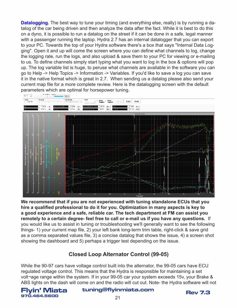
Datalogging. The best way to tune your timing (and everything else, really) is by running a da-talog of the car being driven and then analyze the data after the fact. While it is best to do this on a dyno, it is possible to run a datalog on the street if it can be done in a safe, legal manner with a passenger running the laptop. Hydra 2.7 has an internal datalogger that you can export to your PC. Towards the top of your Hydra software there's a box that says "Internal Data Log-ging". Open it and up will come the screen where you can define what channels to log, change the logging rate, run the logs, and also upload & save them to your PC for viewing or e-mailing to us. To define channels simply start typing what you want to log in the box & options will pop up. The log variable list is huge, to peruse what channels are available in the software you can go to Help -> Help Topics -> Information -> Variables. If you'd like to save a log you can save it in the native format which is great in 2.7. When sending us a datalog please also send your current map file for a more complete review. Here is the datalogging screen with the default parameters which are optimal for horsepower tuning.
We recommend that if you are not experienced with tuning standalone ECUs that you hire a qualified professional to do it for you. Optimization in many aspects is key to a good experience and a safe, reliable car. The tech department at FM can assist you remotely to a certain degree- feel free to call or e-mail us if you have any questions. If you would like us to assist in tuning or troubleshooting we'll generally want to see the following things- 1) your current map file, 2) your left bank long-term trim table, right-click & save grid as a comma separated values file, 3) a concise datalog that shows the issue, 4) a screen shot showing the dashboard and 5) perhaps a trigger test depending on the issue.
Closed Loop Alternator Control (99-05)
While the 90-97 cars have voltage control built into the alternator, the 99-05 cars have ECU regulated voltage control. This means that the Hydra is responsible for maintaining a set volt¬age range within the system. If in your 99-05 car your system exceeds 15v, your Brake & ABS lights on the dash will come on and the radio will cut out. Note- the Hydra software will not
22
[email protected]' Miata970.464.5600
Rev 7.3
read over 15v! This means that your system voltage could be dangerously more! Your controls for this parameter can be found in Tuning maps -> Closed loop -> Alternator Voltage Target and also Settings -> Alternator Voltage Control Settings. The default charging target is 13.7v. Note: Keep in mind that a 94-97 internally regulated Miata alternator will bolt on to a 99-05 car and work with a couple wiring changes, negating the need for ECU alternator control. Contact FM for instruc¬tions on how to set it up if you'd like to do this. Note: if the voltage goes below 11.3v or over 14.8v the WBO2 heater will shut down. In addition, if you see that your WBO2 readout seems to oscillate wildly it’s an indication that your voltage is too high for the liking of that circuit. The solution is to drop your voltage target a couple tenths at a time until the AFR trace stabilizes. You can verify this with datalogs.
You’ll need to calibrate your voltage control since most cars have a variance between voltage measured at the battery & what is displayed in the Hydra screen. Therefore, alter your Alter-nator Voltage Target until the voltage measured at the battery is at your desired voltage tar-get- we recommend around 14.2v for optimal battery life, but you can go down to the mid 13s safely if the aforementioned AFR trace oscillation is an issue. If this variance between the ECU reading & the battery posts seems excessive you may want to re¬move, clean & reinstall all of your chassis grounds in case corrosion is causing resistance in your voltage flow. In addition, if your voltage oscillates too much (you'll see it in your lights) you will need to reduce your Alter-nator Voltage Control P-term value from the default of 200. Try going down 10 points at a time until you achieve stable voltage, or at least stable enough that your lights don't oscillate. If you do have to reduce the P value to damp the oscillation it's a sign that your alternator is getting tired. Note- Factory NBs run around 14.7v at the battery, while factory NAs run about 13.7.
Variable Intake Valve Timing (01-05, except MSM)
On 2001-2005 Miatas (except MSMs) there is a hydraulic assembly on the intake cam that allows for real-time adjustable cam timing between two end points based on a 3D map. Hav-ing control of your valve overlap is an excellent tool- it allows for the user to realize optimal flow rates for both cruise, full throttle, and all points in-between. Without this there is always some compromise involved in cam timing. Warning- improper cam timing can cause increased EGTs, detonation, and also bent valves in interference engines. This variable is not for the amateur tuner! This is a powerful tuning tool that can potentially have an even greater power effect than fuel & timing fine tuning.
To access the cam timing map, go to Tuning maps -> Engine trimming -> VCT Intake Target. In this map you set the amount of intake cam advance & retard in relation to the "zero" position of a non-adjustable cam. In our testing the factory engines tend to have 44°- 45° of total cam range, so for our purposes let's say that the effective range is from -22° to +22°, with 0° being as-if the car had a fixed cam. This -22° full-retard point is where you want it to park for idle & low RPM so that's what we'll calibrate your map to. Note- stock Miata engines are non-interfer-ence. If you have a head shave, aftermarket pistons, high lift cams, or oversized valves you need to determine if your engine has become an interference one. If so, incorrect tuning of this
23
[email protected]' Miata970.464.5600
Rev 7.3
map (too much advance) could put a piston into a valve! If you have an interference engine, or are not sure, unplug your VVT from the harness so the cam is locked at full retard. Wait to activate the VVT & tune the map until the car is in the hands of a qualified tuner.
Calibration. Fortunately there is an easy way to calibrate the FM base VVT map to your car. Once your car is up to temp & idling pop your hood & un-plug your harness connector to the VVT assembly (top front of the intake cam). When you do this the cam will sit at full retard. Note: if this calibration is way off base you may have to unplug the VVT solenoid before the car will start & hold an idle. Next go to Tools -> VCT Target vs. Actual where you can monitor the intake cam target advance vs. actual advance. Then go to Settings -> Ignition Triggers -> VCTi Offset. Alter this number until your actual advance lines up with the target of -22°. After this is done plug the VVT harness back in, and go monitor VCT Target vs. Actual while free-revving to make sure the target & the actual are tracking each other.
Note: The VCTi offset value moves the calibration 1° at a time, which is good for fine-tuning on most cars. In some cases your actual may be way off base of your target & you first have to use the Left VCTi Sequencer, which moves the calibration 10° per point, to get the target vs. actual within 10 points. Common situations where you may have to do this are with the 36-2 timing wheel, or with autocrossers that have the problem where the pressed-on cam trigger wheel rotates on the cam from over-revving all the time. Autocrossers will often tack-weld this wheel to the camshaft to stop this from happening.
For idle and low RPM, there is not enough oil pressure in the system to reliably hold advance in the cam gear, and therefore you should leave the value in the chart at full retard so that it does not even try to advance the cam. Trying to advance it can result in a bad idle or jerky driv-ability. This poor behavior can come from a few different things including the VVT or the AFR being lean, so if you experience it, you can rule VVT in or out by simply unplugging the con-nector from the solenoid and see if the problem goes away. If so, try holding the fully retarded limit to higher in the rev range before you allow any cam advance. (If not, your idle may be lean.) Remember, when you're done tuning this map make sure that the transition points are smooth- large, abrupt changes to the cam advance under load can damage the valve train in the long run and cause poor drivability.
Note- You can retrofit a VVT head or engine to a non-VVT 1.8. It is a lot of work, but it may be worthwhile for your project. Contact FM for the VVT wiring & Hydra settings info you'll need.
Electronic Boost Control for turbo cars
Starting in the R34 Hydra software (with the help menus) there is an excellent tutorial on Hydra EBC at help -> help topics -> how tos -> boost control. Please refer to this for information on how to properly set up this function. Given that, we’re still not entirely satisfied with the closed loop EBC control so at this time we are recommending you set the system up using open loop control. This will give you results similar to a manual boost controller, however you will also benefit from boost assist plus the Hydra can do various boost trims and protections so it’s still an overall better way to go compared to MBC. The base mapping has open loop control al-
24
[email protected]' Miata970.464.5600
Rev 7.3
most all set up for you, you’ll just have to dial in one map for it to meet with the needs of your car. This map is Tuning maps -> Boost control -> Minimum boost solenoid duty cycle. You now need to determine what duty cycle it takes to hit each boost level break point- determine this manually through experimentation and develop your curve. Once the curve is developed, the ECU will use this duty cycle curve as a reference for whatever value you plug into your Tun-ing maps -> Boost control -> Boost target map, plus or minus any trims or protections. If you find you have some droop or creep you can trim it out with max-min boost solenoid duty cycle engine speed trim map. Also, we recommend setting this curve up when the temps are cool & you’re at your lowest normal driving elevation (since temperature & elevation affect boost lev-els). This way, if it gets hot or you go up the boost will go down which is the safest way to have it set up & probably better for your engine that it does anyway.
Note: We recommend setting your tuning maps -> maximum boost map 5 psi or 35 kPa above your boost target. If your car is currently running & you are upgrading, send your current map to [email protected] with the request & we’ll update it with basic EBC starting numbers.
Other Capabilities
The Hydra system is very powerful & gives you lots of potential for peripheral & custom setup & programming. It comes in 5 levels (Alpha / Beta / Gamma / Delta / Epsilon), and each level unlocks new capabilities. (http://www.flyinmiata.com/tech/Hydra_levels.php) There are some things built in to the various levels like auxiliary maps, launch control, Flex Fuel, CAN bus, gear based controls, EGT trims and various other trims. There are also extra inputs & outputs that will allow you to get creative using its various capabilities. We even have FM custom options like our 36-2 trigger wheel & sequential spark system. Some of these things we have used & have base maps for such as our Flex Fuel kit, others we have not but could possibly get you set up in the right direction. Let us know if you need assistance exploring what else the system can do.
We know that while many owners want to “set it & forget it”, we have other customers who like to tinker with the system & explore its capabilities. If you are the type of owner that likes to try out different things in the calibration, and you would like to be on a special email list of owners to whom we will send new things for you to beta test alongside us, let us know & we’ll add your name to this “tester” list. Thanks!
Appendix A- Emissions
The Hydra ECU does not have the ability to return any OBD-2 information for 1996 & newer cars. If you have occasion to need the car to return to OBD-2 functionality then you will need to go back to your stock electronics. This includes the following components: A) The stock ECU. B) The stock fuel injectors. C) The stock ignition coils (if you have switched them). D) The stock mass airflow sensor or airflow meter. E) The stock air temp sensor in NB cars. F) The stock post-cat O2 sensor (assuming you left the pre-cat sensor in the downpipe). G) The stock EGR if you have removed it. (The Hydra does not run EGR.) H) Any other stock electron-ics you have manipulated. I) You must also remove the Hydra WBO2 sensor to prevent dam-age from running it without power. J) Stock N/A heat-range spark plugs (NGK BKR5E-11). K)
25
[email protected]' Miata970.464.5600
Rev 7.3
If you have a turbo / supercharger you may want to wire your wastegate / bypass valve open to reduce the airflow to the engine. -- Once you are running on the stock components you must complete the necessary number of drive cycles for the stock computer to declare all the required codes as "ready". This readiness is not very straightforward so you'll just have to keep driving until it does. Also, and this is important, if your car is turbo or supercharged stay out of boost! If it is high compression N/A stay off of full throttle!
The Hydra-powered engine does have the ability to produce clean tailpipe emissions when it's properly calibrated. The fact that Hydra-powered cars generally get as good or better gas mileage than stock cars underscores this. The basis of this is that first you must have your base fuel table dialed in as close as you can so that any day-to-day variances in fuelling can easily be trimmed out by the closed loop O2 sensor system. Beyond that, here are some hints to improve your engine's emissions. Start by saving your working map before making all these changes for your emissions map so that you can revert easily after the test. A) The factory NBO2 sensor is better at regulating stoichiometric emissions than the WBO2 sensor is. Switch the Hydra control back to the left narrowband sensor under Settings -> AFR target settings -> Left module sensor source (assuming you still have the NBO2 sensor installed). Make sure the left module closed loop & long term trim are both enabled. B) In your AFR target table, assum-ing you are doing this for tailpipe testing & not for normal driving, set your target to 14.7 across the board. This will ensure that no matter what the worker at the test station does with his right foot the computer will be trying to trim it for stoichiometric. C) Set your throttle pump fuel trim table, throttle tip-in fuel trim table, post-start fuel trim decay & your post-decel cut fuel trim tables to 0 across the board. This will prevent the worker's digital right foot from throwing rich spikes into the test. Also drop your Closed Loop Start Delay table to 0. D) Drop your base idle speed target down to the target RPM on the emissions sticker under your hood. E) Drop your maximum boost down to around say 4 PSI / 128 kPa so that the ECU won't let the engine go into boost. F) Turn off air conditioning (including defrost on 2001-05 cars) and other electrical loads. G) Zero out your post start idle speed target trim, post start fuel trim, post start throttle pump fuel trim & (closed loop) start delay maps to keep it from being rich when the operator runs the test immediately after stalling your engine & restarting it. H) Make sure the car will still hot restart smoothly after doing all of these things. I) Set your fan temperatures hotter so that the engine runs hot, say 105°C / 221°F. J) If you have a well-developed LTT table you should apply it back to your base fuel table, and zero out your LTT table. We have a spreadsheet available for doing this manually- email us if you need a copy.
While emissions test results can never be guaranteed, these things can help hedge your bets. To take it any farther than this you would really need access to a 5 gas analyzer so you could really dial in your ignition advance & cam timing in VVTi cars for the lowest possible emissions. Note- while our FM high flow catalytic converters are high quality 3-way cats, they are also high flow. A healthy factory cat will produce better emissions test results so you may want to keep yours on hand, just in case.