meridianâ„¢ - digimap
TRANSCRIPT
Meridian User Guidev2.0 - 1/1997 © Crown copyright
Meridian™
User Guide

Meridian User Guidev2.0 - 1/1997 © Crown copyright
Preface
Meridian User Guidev2.0 - 1/1997 © Crown copyright
Preface
Thank you for choosing Meridian™ for your business needs.
This User Guide contains all the information you need to makeeffective use of Meridian™.
The User Guide is in two parts: the Meridian ™ ReferenceSection is designed to help you understand the informationcontained in the data; the Meridian ™ Format Section isdesigned to help you load the data into your software.

Preface
Meridian User Guidev2.0 - 1/1997 © Crown copyright

Meridian User Guidev2.0 - 1/1997 © Crown copyright
Meridian™ User Guide
Contact DetailsCustomer Services - Digital Help Desk will be pleased to deal with yourenquiries.Customer Services - Digital Help DeskTelephone: 01703 792773Fax: 01703 792324E-mail: [email protected]
or write to:
Customer Services - Digital Help DeskOrdnance SurveyRomsey RoadSOUTHAMPTONUnited KingdomSO16 4GU
Product PerformanceIf you have any problems or identify any errors in the data, please completethe Product Performance Report Form at Appendix E in the ReferenceSection.
LiabilityThis User Guide has been checked and validated before issue and everyendeavour made to ensure that the contents are accurate. If you find anyerrors or omissions please write to us at the address shown above so thatwe can investigate them.
Ordnance Survey makes every effort to ensure that data supplied are freefrom errors and omissions. We will remedy, as soon as reasonablypracticable, errors and omissions the Customer notifies to Ordnance Surveyin writing. It is the Customer's responsibility to ensure that data ordered aresuitable for the intended purpose. Ordnance Survey will not be liable to theCustomer or any other party for any loss, damage, inconvenience orexpense resulting from the use of, or reliance upon, the data.
Trade MarksOrdnance Survey and Land-Line are registered trade marks and the OSsymbol and Meridian are trade marks of Ordnance Survey, the NationalMapping Agency of Great Britain.
MS-DOS is a registered trade mark of Microsoft Corporation in the UnitedStates and other countries. UNIX is a registered trade mark of UNIXSystems Laboratories. AutoCAD is a registered trade mark and DXF is atrade mark of Autodesk Inc.

Meridian™ User Guide
Meridian User Guidev2.0 - 1/1997 © Crown copyright
Table of Contents
Meridian User Guidev2.0 - 1/1997 © Crown copyright
Contents Page 1
Reference Section Contents
Preface
Chapter 1 Introduction 1.1
Meridian Features 1.2
Applications of Meridian 1.3
What You Need to Use Meridian 1.4Computer Hardware 1.4Computer Software 1.4
Output of Meridian Information 1.5
Supply 1.6Meridian Supply Options 1.6Meridian Supply Formats 1.6Meridian Supply Media 1.6
Chapter 2 Overview of Meridian 2.1
Data Overview 2.1Basic Principles 2.1Meridian Vector Data Structure 2.2
Chapter 3 Meridian Explained 3.1
Features 3.1
Points and Lines 3.2
Feature Position 3.5
Feature Attribute Data 3.6Feature Codes 3.6Names as Attributes 3.8Road Number 3.8Trunk Road 3.8Junction Name 3.9Unique Identifiers 3.10Link Level at Node 3.11
Feature Layer Descriptions 3.12Roads 3.12Railways 3.12Administrative Areas and Coastline 3.13
Table of Contents
Meridian User Guidev2.0 - 1/1997 © Crown copyright
Contents Page 2
Developed Land Use Areas 3.14Cartographic Names 3.15
Appendix A Quality Statement A.1
Source of Meridian A.1
Currency A.2
Accuracy and Resolution A.2
Completeness A.2
Appendix B The National Grid B.1
Appendix C Glossary C.1
Appendix D Terms and Conditions D.1
Use of Meridian D.1
Delivery of Meridian D.1
Invoice D.1
Copyright D.2
Appendix E Product Performance Report Form E.1

Table of Contents
Meridian User Guidev2.0 - 1/1997 © Crown copyright
Contents Page 3
Format Section Contents
Chapter 1 Introduction 1.1
Meridian General Specifications 1.2
Chapter 2 Introduction to Data Formats 2.1
NTF 2.1
Drawing Interchange File (DXF) 2.4
Chapter 3 NTF Explained 3.1
Chapter 4 DXF Explained 4.1
Introduction 4.1
Overview 4.1Structure of Meridian 4.1
Drawing Content and Format 4.3Coordinate System 4.3Height 4.3Layer Names 4.3Neatline 4.3Grid 4.4Grid Values 4.4DXF Layers 4.5
Appendix A NTF File Structure for Meridian A.1
An Overview of the Data in NTF A.1Outline Description of the Data Structure A.2Supply of Data on Unformatted Media A.3Supply of Data on Formatted Media A.4
Version Management A.7
General A.7
Section Body A.8Point and Line Features A.8Name Detail A.9Node Detail A.10
Feature Information Relevant to NTF A.11
Table of Contents
Meridian User Guidev2.0 - 1/1997 © Crown copyright
Contents Page 4
Point Features A.11Line Features A.11Coordinates A.12Bearings A.12Attribute Codes A.13Unique Identifiers A.14Record IDs A.14
Feature Layers A.16
Record Breakdown A.18NTF Record List A.18Volume Header Record [VOLHDREC] 01 A.19Database Header Record [DBHREC] 02 A.20Feature Classification Record [FEATCLASS] 05 A.21Section Header Record [SECHREC] 07 A.22Attribute Record [ATTREC] 14 A.24Point Feature Record [POINTREC] 15 A.33Node Record [NODEREC] 16 A.34Two-Dimensional Geometry Record [GEOMETRY1] 21 A.35Line Feature Record [LINEREC] 23 A.37Attribute Description Record [ATTDESC] 40 A.38Text Record [TEXTREC] 43 A.40Text Position Record [TEXTPOS] 44 A.41Text Representation Record [TEXTREP] 45 A.42Volume Terminator Record [VOLTERM] 99 A.43
Appendix B DXF File Structure for Meridian B.1
General B.1
Data Structure B.2Header B.3Tables B.6Blocks B.12Entities Section B.13End of File Group B.17
Chapter 1 Introduction
Meridian User Guidev2.0 - 1/1997 © Crown copyright
Reference Section - Page 1.1
Chapter 1 Introduction
This Reference Section is designed to enable users to makeeffective use of Meridian, and contains all the information youwill need.
This Chapter and Chapter 2 provide an introduction to Meridianand illustrate potential applications. Chapter 3 contains details ofthe components of the data. Please refer to the Glossary if youare unfamiliar with the terms used.
All aspects of Meridian discussed in this User Guide relate toMeridian in both BS 7567 (NTF v2.0) and DXF (AutoCADRelease 12) formats. If the two format versions differ in theirtreatment of a particular aspect, the specific differences will bestated. Icons, as shown below, will be used to denote thesedifferences.
For convenience BS 7567 (NTF v2.0 level 2) isreferred to as NTF in this Section.
Drawing Interchange File (DXF) is referred to as DXFin this Section.
For information on the Meridian data format, please refer to Part2 of the User Guide.
Ordnance Survey’s Meridian provides a comprehensive nationaldatabase of geographic (spatial) information designed tosupport a wide range of applications including initial planningand project work at a regional level. Concepts of Meridian areexplained fully in Chapter 2.
Appropriate software is required to facilitate the customer’sintended application.
The database has been derived from Ordnance Survey’sexisting large and small scales digital databases. Railways havebeen digitised from Ordnance Survey’s 1:50 000 Scale ColourRaster data.
DXF
BS 7567
NTF
Chapter 1 Introduction
Meridian User Guidev2.0 - 1/1997 © Crown copyright
Reference Section - Page 1.2
Meridian Features● Meridian has feature codes which allow everything in the
database to be allocated to a specific category; users cangroup like-features for search, display and output routines.
● Meridian is defined as a limited ‘link and node’ structurewithin each layer. It contains points, lines and nodes. Nodeshave pointers to lines that join at the node and similarly,there are lines that enclose an area containing a point. Somepoints are not contained within areas enclosed by lines.
● Department of transport road classification numbers arestored in attribute records and are applied to features suchas roads. Names applying to administrative areas anddeveloped land use areas are also included in the attributerecord of the appropriate point feature
● Annual updating of source databases ensures that highstandards of currency and integrity are maintained.
● Enhancement of Meridian incorporating selected additionalfeatures is proposed from October 1997.

Chapter 1 Introduction
Meridian User Guidev2.0 - 1/1997 © Crown copyright
Reference Section - Page 1.3
Applications of Meridian
There are many potential applications for Meridian. Theseinclude:
● Environmental analysis
● Land management
● Commercial/business site development
● Routing Analysis
● Retail/Wholesale Trades● Distribution networks● Store/warehouse locations● Strategic business expansion/development
● Marketing and Media Planning● Sales force locations/territories● Sales prospecting● Market analysis of customers, competitors or outlet
densities● Market analysis of direct mail responses● Poster distribution● TV/Radio advertising Regions● Product/Brand promotion campaigns
● Financial/Insurance● Customer bases● High/Low risk areas
● Health● Community health● Health black-spots
● Leisure Activities● Large site planning, e.g. golf courses● Tourism● Theme Park locations.
Chapter 1 Introduction
Meridian User Guidev2.0 - 1/1997 © Crown copyright
Reference Section - Page 1.4
What You Need to Use Meridian
Computer Hardware
Providing that sufficient memory and storage facilities areavailable there are no constraints on hardware platforms whichcan be used. The range of hardware which can typically be usedvaries from higher specification personal computers (PCs) tomainframe computers.
Computer Software
Meridian is inert data and does not include software for datamanipulation. To exploit fully the potential of Meridian it isnecessary to use appropriate application software. There aremany proprietary systems available and Ordnance Surveypublishes a list of Geographical Information Systems (GIS),CAD and Digital Mapping System Suppliers who have confirmedtheir software can import NTF format. Contact CustomerServices - Digital Help Desk for a current list of these details,see Contact Details at the beginning of this User Guide.
Chapter 1 Introduction
Meridian User Guidev2.0 - 1/1997 © Crown copyright
Reference Section - Page 1.5
Output of Meridian Information
Meridian is inert data. It requires software (not provided byOrdnance Survey) to display it on a screen or to plot it out ashard copy.
The parameters defining colours, line styles, textstyles, symbols, etc. should be built into usersoftware. Symbol definitions used by OrdnanceSurvey are given in the Meridian Format Section.
The parameters defining colours, line styles, textstyles, symbols, etc. are embedded within the DXFfile, as is customary with this CAD format.
Meridian may be customised by viewing or plotting features indifferent colours, line styles and scales to suit differentapplications. Certain classes of features may be omitted fromcustomised plans on the basis of selection by feature code.
DXF
BS 7567
NTF
Chapter 1 Introduction
Meridian User Guidev2.0 - 1/1997 © Crown copyright
Reference Section - Page 1.6
Supply
Meridian Supply Options
The options for data supply are as follows:
● Complete national cover of Great Britain (805 tiles)
● Regional Area data are supplied along tile lines containingwhole counties.● Northern Scotland (205 tiles)● Southern Scotland (151 tiles)● Northern England (134 tiles)● West and East Midlands (101 tiles)● South East England (134 tiles)● South West England (98 tiles)● Wales (84 tiles)(these areas correspond with Nomenclature des UnitesTerritoriales Statistique (NUTS) Level 1 Areas)
● 20 km by 20 km tiles
Meridian Supply Formats
Meridian is available in:
BS 7567 (NTF v2.0 Level 3)
DXF (conforming to AutoCAD release 12 with ExtendedEntity Data).
Meridian Supply Media
NTF is supplied on the standard Ordnance Survey mediaoptions.
DXF is supplied on CD-ROM only.
Chapter 2 Overview of Meridian
Meridian User Guidev2.0 - 1/1997 © Crown copyright
Reference Section - Page 2.1
Chapter 2 Overview of Meridian
Data Overview
Basic Principles
Links represent roads, railways, administrative areas, coastlineand developed land use area lines.
Nodes represent all intersections of links within each layer,changes in attributes in links and link ends.
Each feature has associated geometry; this may be a singlecoordinate pair for a single point feature for a railway station ortwo or more coordinate pairs for a linear feature.
Each feature is classified by means of a feature code.
Roads, railways, railway stations, administrative area seedpoints and developed land use area seed points have uniqueidentifiers.
Chapter 2 Overview of Meridian
Meridian User Guidev2.0 - 1/1997 © Crown copyright
Reference Section - Page 2.2
Meridian Vector Data Structure
Meridian data within each layer are supplied as vector data, in alink and node structure. Geographical features are representedas data entities either as points or lines. Points are fixedpositionally by one coordinate pair, e.g. a railway station. Linesare fixed positionally by a series of connected coordinate pointsto represent linear map features such as roads, railways, etc.Points and lines within the data model determine the geometric(positional) characteristics of the data.
Points and lines within the data model also have associatedattributes. These give the point and line entities meaning, i.e.they represent the descriptive characteristic of an entity such asa feature code, a name or numerical value. Lines are alsoadded as closing links (neat lines) along tile edges; these arerequired to complete the enclosure of an area. The closing linkhas a different feature code to the other links enclosing the area.
Throughout the Meridian product no line feature crosses fromone tile to the next, but a point feature created at the tile edgehas the same coordinate value as its partner on the adjacenttile.
All features having the same Feature Code arerecorded on the same layer. DXF has a limited ‘linkand node’ structure; within this structure, a featuremay be a name, point or line. Each feature isfree-standing, i.e. its topological relationship to anyother feature is not expressed in the data.
Other important data structure concepts include networks andpolygons .
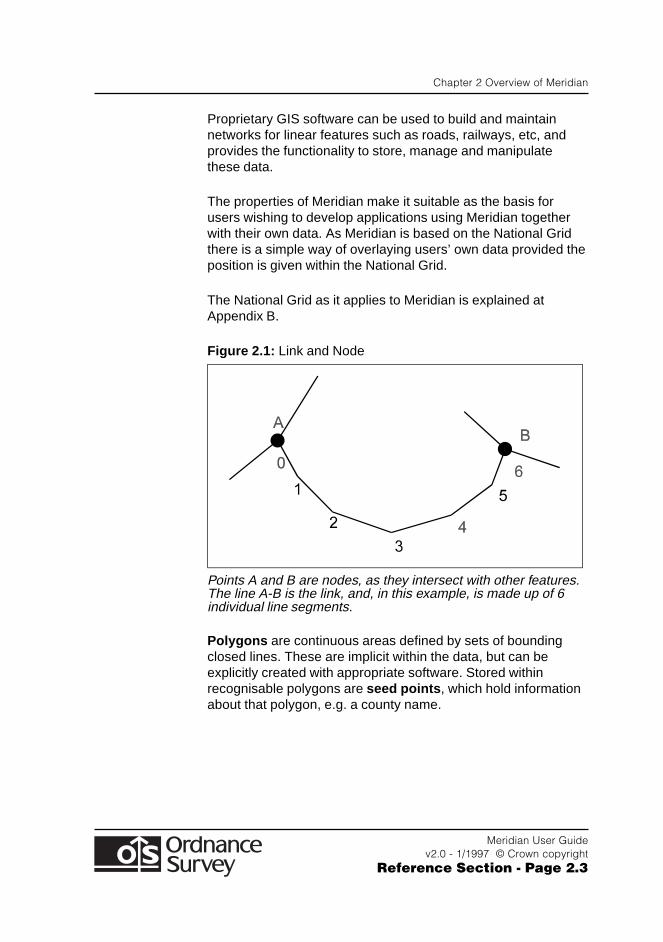
Networks are interconnecting features structurally related bymeans of an explicit point described as a node . Between thenodes are series of non-intersecting line segments described aslinks ; hence link and node - see figure 2.1. This is of specialinterest in GIS where there may be a need to analyse thenetwork in order to follow routes or to close polygons.
DXF
Chapter 2 Overview of Meridian
Meridian User Guidev2.0 - 1/1997 © Crown copyright
Reference Section - Page 2.3
Proprietary GIS software can be used to build and maintainnetworks for linear features such as roads, railways, etc, andprovides the functionality to store, manage and manipulatethese data.
The properties of Meridian make it suitable as the basis forusers wishing to develop applications using Meridian togetherwith their own data. As Meridian is based on the National Gridthere is a simple way of overlaying users’ own data provided theposition is given within the National Grid.
The National Grid as it applies to Meridian is explained atAppendix B.
Figure 2.1: Link and Node
Points A and B are nodes, as they intersect with other features.The line A-B is the link, and, in this example, is made up of 6individual line segments.
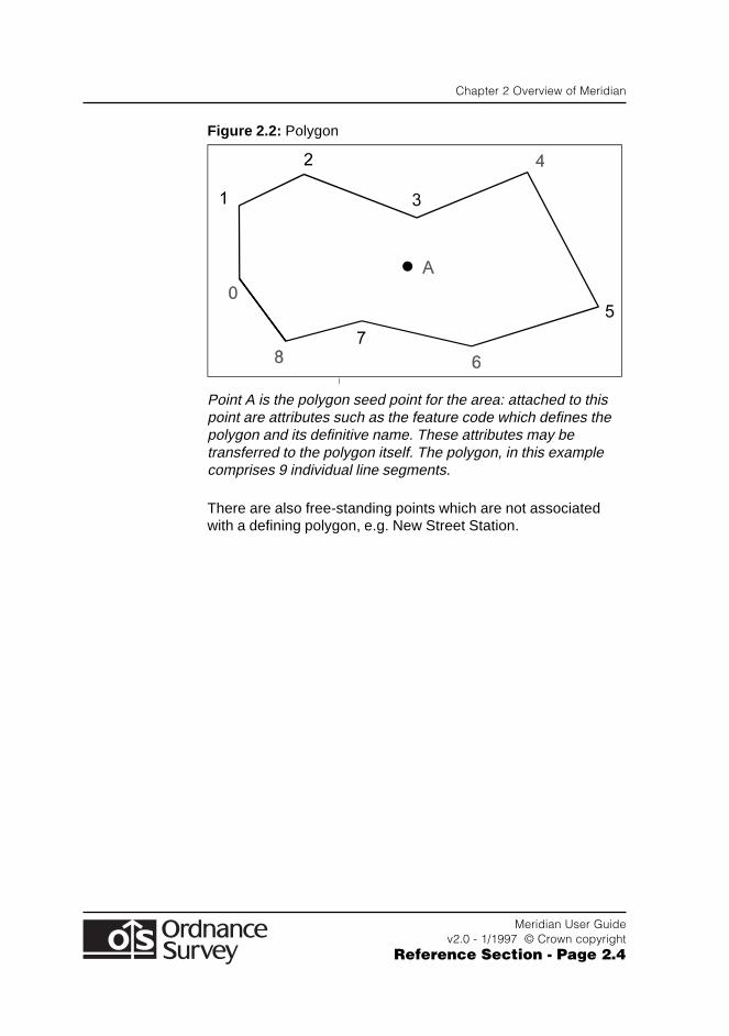
Polygons are continuous areas defined by sets of boundingclosed lines. These are implicit within the data, but can beexplicitly created with appropriate software. Stored withinrecognisable polygons are seed points , which hold informationabout that polygon, e.g. a county name.
Chapter 2 Overview of Meridian
Meridian User Guidev2.0 - 1/1997 © Crown copyright
Reference Section - Page 2.4
Figure 2.2: Polygon
Point A is the polygon seed point for the area: attached to thispoint are attributes such as the feature code which defines thepolygon and its definitive name. These attributes may betransferred to the polygon itself. The polygon, in this examplecomprises 9 individual line segments.
There are also free-standing points which are not associatedwith a defining polygon, e.g. New Street Station.
Chapter 3 Meridian Explained
Meridian User Guidev2.0 - 1/1997 © Crown copyright
Reference Section - Page 3.1
Chapter 3 Meridian Explained
Features
Meridian has two feature classes:
● Point features
● Line features.
Point features such as administrative area seed points and linefeatures such as roads, railways and developed land use areasare arranged into recognisable categories. A full listing ofindividual features is given in Appendix A of the Format Section.
Each feature has two components:
● Feature position
● Feature attribute data.
Also covered in this Chapter:
● Feature layer descriptions.
Each feature recorded in Meridian should beconsidered as a DXF Entity. Line features arerecorded as DXF Line(s) or Polyline(s).
Point features will be recorded in the data as INSERTBLOCKS. Certain standard symbols are defined inthe BLOCKS section of the data file. A list of thesestandard symbols is shown in the Format Section.Attributes are stored as Extended Entity Data.
DXF
DXF
Chapter 3 Meridian Explained
Meridian User Guidev2.0 - 1/1997 © Crown copyright
Reference Section - Page 3.2
Points and Lines
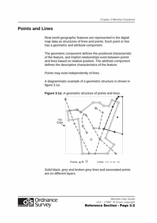
Real world geographic features are represented in the digitalmap data as structures of lines and points. Each point or linehas a geometric and attribute component.
The geometric component defines the positional characteristicof the feature, and implicit relationships exist between pointsand lines based on relative position. The attribute componentdefines the descriptive characteristics of the feature.
Points may exist independently of lines.
A diagrammatic example of a geometric structure is shown infigure 3.1a.
Figure 3.1a: A geometric structure of points and lines.
TileEdge
Points Lines
Solid black, grey and broken grey lines and associated pointsare on different layers.
Chapter 3 Meridian Explained
Meridian User Guidev2.0 - 1/1997 © Crown copyright
Reference Section - Page 3.3
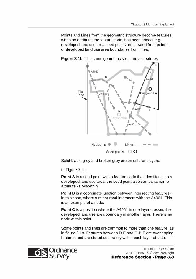
Points and Lines from the geometric structure become featureswhen an attribute, the feature code, has been added, e.g.developed land use area seed points are created from points,or developed land use area boundaries from lines.
Figure 3.1b: The same geometric structure as features
Bryncethin
Bridgend UA
A4061
A4063
A4061
A4061
A
B
C
G
DE
F
A4063
TileEdge
Nodes Links
Seed points
Solid black, grey and broken grey are on different layers.
In Figure 3.1b:
Point A is a seed point with a feature code that identifies it as adeveloped land use area, the seed point also carries its nameattribute - Bryncethin.
Point B is a coordinate junction between intersecting features -in this case, where a minor road intersects with the A4061. Thisis an example of a node.
Point C is a position where the A4061 in one layer crosses thedeveloped land use area boundary in another layer. There is nonode at this point.
Some points and lines are common to more than one feature, asin figure 3.1b. Features between D-E and G-B-F are overlappingfeatures and are stored separately within each layer of data.
Chapter 3 Meridian Explained
Meridian User Guidev2.0 - 1/1997 © Crown copyright
Reference Section - Page 3.4
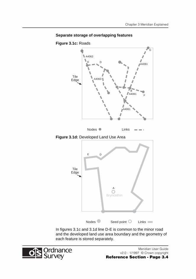
Separate storage of overlapping features
Figure 3.1c: Roads
A4061
A4063
A4061
A4061
B
G
DE
F
A4063
TileEdge
Nodes Links
Figure 3.1d: Developed Land Use Area
Bryncethin
A
DE
TileEdge
Nodes LinksSeed point
In figures 3.1c and 3.1d line D-E is common to the minor roadand the developed land use area boundary and the geometry ofeach feature is stored separately.
Chapter 3 Meridian Explained
Meridian User Guidev2.0 - 1/1997 © Crown copyright
Reference Section - Page 3.5
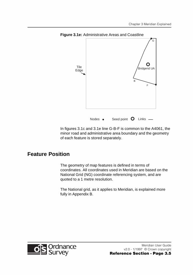
Figure 3.1e: Administrative Areas and Coastline
B
G
F
TileEdge
Nodes Seed point Links
Bridgend UA
In figures 3.1c and 3.1e line G-B-F is common to the A4061, theminor road and administrative area boundary and the geometryof each feature is stored separately.
Feature Position
The geometry of map features is defined in terms ofcoordinates. All coordinates used in Meridian are based on theNational Grid (NG) coordinate referencing system, and arequoted to a 1 metre resolution.
The National grid, as it applies to Meridian, is explained morefully in Appendix B.
Chapter 3 Meridian Explained
Meridian User Guidev2.0 - 1/1997 © Crown copyright
Reference Section - Page 3.6
Feature Attribute Data
An attribute is the descriptive characteristic of a feature, i.e. anon-spatial element.
The geometry of the points and lines within the data would bemeaningless to the user unless they are assigned somedistinguishing property. In Ordnance Survey map data terms, anattribute can be a feature code (in NTF these are numericcodes), e.g. 6001, or a distinctive name or number, e.g.‘Birmingham’ or ‘M40’.
Attribute codes relevant to NTF are listed and described withinthe Format Section but an overview is given below.
Feature Codes
Each feature is classified by means of a feature code (FC). Afeature code is allocated when each feature is initiallyinterpreted and captured from the map base. In this way, an Aroad is distinguished, by the feature code allocated to it, from aB road and other kinds of line feature.
Each feature is classified as belonging to a specificfeature layer. These layers range in value fromG8050570 to G8056801, using the BS 1192 Part 5Guide for structuring of computer information. Thesefeature layers are listed in Chapter 2 of the FormatSection. Attributes are stored as Extended EntityData .
A further four text feature codes for Layout ofFootnotes are included. These feature codes arelisted in the Format Section.
DXF
Chapter 3 Meridian Explained
Meridian User Guidev2.0 - 1/1997 © Crown copyright
Reference Section - Page 3.7
In order to display the attributes stored as extendedentity data, the following two scripts are required.These two files, ‘Showeed.lsp’ and ‘ Showeed.dcl’,are contained in the ‘EXE’ directory on the OrdnanceSurvey-supplied CD-ROM and should be placed in adirectory in the AutoCAD preferences search string.This should include the directory containing the mapdata files in DXF.
To utilise the scripts, type the following at theAutoCAD command line prompt within a drawingsession:
AutoCAD: (load "showeed")AutoCAD: eedd
Selecting a map feature will now display the alliedattributes of that feature in a dialogue box. Tointerrogate other features, the ‘Re-Select’ option onthe user dialogue box should be chosen. The ‘Cancel’option will return the user to a normal AutoCADsession.
If the ‘eedd’ command is repeated at the commandprompt, the facility will again be available to the user.
The visibility of extended entity data to software otherthan AutoCAD Release 12 will be constrained by thefunctionality of those individual software applications.
Each feature is classified as belonging to a specificfeature code. These feature codes are listed inChapter 2 of the Format Section.
These differences in the data are inferred during translation fromOrdnance Survey’s internal data format to the required customertransfer format.
BS 7567
NTF
Chapter 3 Meridian Explained
Meridian User Guidev2.0 - 1/1997 © Crown copyright
Reference Section - Page 3.8
Names as Attributes
The criteria for names attribute attachment are as follows:
● Admin Name (NM) is an attribute of a seed point in itsadministrative area, e.g. Hampshire County
● Proper Name (PN) is an attribute of a seed point in adeveloped land use area, e.g. Bexhill, or a node point for arailway station, e.g. Great Ayton Station
● Text (TX) is a text string transferred in an attribute record tobe displayed as ‘standalone’ cartographic text, e.g. Sidley, aplace name.
Road Number
The Road Number (RN) attribute defines the Department ofTransport (DoT) road classification number e.g. M40 whichrelates to a link. If a road is not classified then this attribute willnot be present.
Trunk Road
The Trunk Road (TR) attribute defines whether the link formspart of a trunk road. If it is then the link will have a trunk roadattribute with a value of ‘Y’ and if it is not a trunk road then therewill be no value in this field.
Chapter 3 Meridian Explained
Meridian User Guidev2.0 - 1/1997 © Crown copyright
Reference Section - Page 3.9
Junction Name
The Junction Name (JN) attribute indicates the junction numberof motorway junctions, and the other classified roads at thatjunction. The junction name is variable length text, and is in theformat ‘M6J10A’, where ‘M6’ is the DoT road number, and‘J10A’ indicates that this is the junction numbered 10A of theM6. If the junction has no junction number, then that part of thejunction name is not supplied.
There could be any number of roads at a junction, thereforeeach classified road at that junction may be repeated in thejunction name attribute. Each road number and junction isseparated by a forward slash character (/). The following is anexample of a junction name attribute:
M40J1/A40/A413/A4020
This attribute only applies to nodes . If the node does not have ajunction name, then this attribute is not present.
Chapter 3 Meridian Explained
Meridian User Guidev2.0 - 1/1997 © Crown copyright
Reference Section - Page 3.10
Unique Identifiers
Unique Identifiers are used to uniquely identify some featureswithin Meridian. These are:
● Ordnance Survey Meridian Database Reference(OSMDR). This uniquely identifies any road link or road nodewithin the national Meridian database and is compatible withthe OSCAR family of products. Interchange of data betweenMeridian and OSCAR is possible with software modification.
● Railway and Railway Station Identifiers. These uniquelyidentify any railway link or railway station within the nationalMeridian database.
● Developed Land Use Area Identifier . This uniquelyidentifies any developed land use area seed point within thenational Meridian database.
● Global Identifier . This uniquely identifies any AdministrativeArea seed point within the 20 km by 20 km tile.
The Unique Identifiers are unique references and will bemaintained, except where there has been significant change toa feature.
The Unique Identifier may refer to several links representing alinear object across tiles, e.g. a road or a railway, which may bechained together across tile edges. Thus, on adjoining tiles,there may be two or more links with the same unique identifier.
Unique identifiers have been assigned to all existing roads (linksand nodes), railway links and railway stations and to seed pointsfor administrative areas and developed land use areas. Any ofthese features which are new to Meridian after the initialallocation will be assigned an appropriate unique identifier whenthe database is refreshed.
The Unique Identifier for a feature will never be modified - onlycreated and deleted. If a feature is deleted from the Meridiandatabase, then the Unique Identifier allocated to that feature willcease to exist.
Chapter 3 Meridian Explained
Meridian User Guidev2.0 - 1/1997 © Crown copyright
Reference Section - Page 3.11
OSMDR There may be many changes to a feature with aspecific OSMDR during the lifetime of that OSMDR allocation.There are two reasons for these changes:
1. The coordinates of the feature may move within a specifiedtolerance - currently 3 metres. Any changes to the featurewithin this tolerance will mean that the OSMDR will beretained for the feature.
2. The attributes associated with a feature may change. Anychanges to these attributes will not affect the OSMDRallocated to that feature. The following attributes may changefor link features:
● Feature Code
● Trunk Road indicator
● Road Number
The following attributes may change for node or point features:
● Direction of Links at Node
● Feature Code
● Junction Name
● Number of Links at Node
● Level of Link at Node
● Name
If a feature moves by more than the specified tolerance,currently 3 metres, then the OSMDR for the feature will bedeleted and a new OSMDR allocated to that feature.
Link Level at Node
In Chapter 2 of the Format Section, the level field in NodeRecord 16 indicates - for roads - the relative height relationshipbetween intersecting links at a node. It does not relate to groundsurface level. If a road over a bridge can be accessed then alevel value of 0 is used; a value of 1 used when there is noaccess from one road to the other at an intersection.
Chapter 3 Meridian Explained
Meridian User Guidev2.0 - 1/1997 © Crown copyright
Reference Section - Page 3.12
Feature Layer Descriptions
The feature codes which appear in Meridian within each layerare detailed in Chapter 2 of the Format Section . The individuallayers, are described in the following sub-sections:
Note: Names or numbers appear in all layers as attributes.
Roads
Motorways, major and minor roads are represented in the data.Complex junctions are collapsed to single nodes andmulti-carriageways to single links. To avoid congestion someminor roads and cul-de-sacs are not represented in the minorroad feature description of the data. Private roads and tracksare not included.
Railways
All railway stations open to passengers and multiple and singletrack passenger lines are represented.
A railway intersection consists of links and a node, but whererailways cross at different levels, links are not broken. Links andnodes carry a feature code. Points carry a railway station nameif it differs from the built up area name on Ordnance Survey's1:50 000 scale colour raster data, e.g. New Street Station inBirmingham, or if the railway station name is not associated toany built up area name, e.g. Great Ayton Station. These nodeattributes are also shown as cartographic station names.
To maintain positional relationship, features in this layer may beadjusted and fitted to the roads.
Chapter 3 Meridian Explained
Meridian User Guidev2.0 - 1/1997 © Crown copyright
Reference Section - Page 3.13
Administrative Areas and Coastline
Administrative areas includes information for new UnitaryAuthority Areas for Scotland and Wales and County, District andLondon Borough boundaries for England.
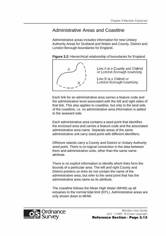
Figure 3.2: Hierarchical relationship of boundaries for England
Each link for an administrative area carries a feature code andthe administrative level associated with the left and right sides ofthat link. This also applies to coastline, but only to the land sideof the coastline, i.e. no administrative area information is addedto the seaward side.
Each administrative area contains a seed point that identifiesthe enclosed area and carries a feature code and the associatedadministrative area name. Separate areas of the sameadministrative unit carry seed point with different identifiers.
Offshore islands carry a County and District or Unitary Authorityseed point. There is no logical connection in the data betweenthem and administrative units, other than the same nameattribute.
There is no explicit information to identify which links form thebounds of a particular area. The left and right County andDistrict pointers on links do not contain the name of theadministrative area, but refer to the seed point that has theadministrative area name as its attribute.
The coastline follows the Mean High Water (MHW) up allestuaries to the normal tidal limit (NTL). Administrative areas areonly shown down to MHW.
Chapter 3 Meridian Explained
Meridian User Guidev2.0 - 1/1997 © Crown copyright
Reference Section - Page 3.14
The administrative areas are adjusted to the coastline.
To maintain positional relationship, features in this layer may beadjusted and fitted to roads and railways.
The Local Authorities of Wales and Scotland have beenchanged to create a single tier of administration at the locallevel, operative from 1 April 1996. These boundaries have beenincluded in the Meridian database.
Local Government in England is still under review althoughsome counties have been concluded. The operative dates forthe new authorities extend from 1 April 1995 through to 1 April1998. In view of this gradual change-over from two-tier LocalGovernment to a mixture of single- or two-tier authorities, theAuthorities in place at 1 April 1994, and currently still inoperation, have been used on this occasion. An exception tothis is the Isle of Wight which is already a single-tier Authority.
Developed Land Use Areas
Developed land use area features include cities, towns, villagesand industrial, commercial and business parks.
Developed land use area features are enclosed by link features.Such areas contain a seed point that identifies the enclosedarea and carry a feature code and the associated developedland use area name. There is no explicit information to identifywhich link forms the bounds of a particular area.
The whole developed land use area has been positioned to theroad pattern by ‘best fit’ practice.

Chapter 3 Meridian Explained
Meridian User Guidev2.0 - 1/1997 © Crown copyright
Reference Section - Page 3.15
Cartographic Names
Place names from the Small Scales database and railwaystation attribute names are also shown as independent textfeatures and located near the feature that they describe.
Place names are collapsed from double-banked, treble-bankedor composite text to a single text feature with all the text as onestring.
The text font ‘STANDARD’ and text height in metreshave been used for these cartographic names andare as layers separate from the feature with whichthey are associated.
The text font identifier of 0004 (Univers MediumRoman Condensed) and text height in millimetres hasbeen used for these cartographic names and istransferred with the text feature.
The Ordnance Survey convention for the digitising of names isas follows: all names are digitised as point features, given as Xand Y National Grid coordinates. The point has been digitisedrelative to the map feature it describes, and the actual pointrepresents one of the standard positions as illustrated below:
Figure 3.3: Standard Ordnance Survey text positions
0
1
2
3
4
5
6
7
8
Names are normally placed on the printed map parallel to thehorizontal grid.
DXF
BS 7567
NTF
Chapter 3 Meridian Explained
Meridian User Guidev2.0 - 1/1997 © Crown copyright
Reference Section - Page 3.16
Position 0 is supplied.
The text string may start, end or be centred on thiscoordinate pair; the relationship of the text to itscoordinate pair is expressed as an ‘original digitisedposition’. Where the position of text features arerecorded, one of these positions is digitised.
DXF
BS 7567
NTF
Appendix A Quality Statement
Meridian User Guidev2.0 - 1/1997 © Crown copyright
Reference Section - Page A.1
Appendix A Quality Statement
Source of Meridian
Meridian data are derived from Large and Small Scales digitaldatabases. The data capture source and scales are:
Feature Data Source Source Scale
Road network Road centre-lines 1:1250, 1:2500database and 1:10 000
County, District and Boundaries 1:10 000London Borough databaseboundariesfor England
Unitary Authority Boundaries 1:10 000Areas for Wales database
Unitary Authority Large Scales 1:1250, 1:2500Areas for database and 1:10 000Scotland
Coastline Small Scales 1:50 000database
Developed Land Small Scales 1:250 000Use Area databaseand place names
Main railways, railway stations and station names have beendigitised from Ordnance Survey’s 1:50 000 Scale Colour Rasterdata for Meridian.
Appendix A Quality Statement
Meridian User Guidev2.0 - 1/1997 © Crown copyright
Reference Section - Page A.2
Currency
Meridian data are derived from the latest available versions ofOrdnance Survey’s databases. The Meridian database will berefreshed annually commencing October 1997.
The Large and Small Scales databases are controlled by therevision criteria for topography that are defined by OrdnanceSurvey for the various geographical areas.
Accuracy and Resolution
The resolution of the data supplied is 1 metre. Meridian dataretains the same accuracy as the source data during its capture.However, it is not possible to calculate meaningful accuracycriteria for these data due to different source databases.
Administrative areas and roads data have a 20 metre lateralfilter applied to the boundary and centre-lines. The 20 metrefilter does not affect the positional accuracy of node points.
Features derived from the Small Scales databases have beensubjected to generalisation where accurate positionalrepresentation would have caused confusing clutter. Tomaintain positional relationships such data have been furtheradjusted to roads and railways where necessary.
Completeness
During production many checks are undertaken to ensure thatdata supplied to customers are both accurate and complete.
These quality control checks take the form of:
● visual checks by operators
● independent quality assurance checks
● computer validation within the flowline.
Appendix B Quality Statement
Meridian User Guidev2.0 - 1/1997 © Crown copyright
Reference Section - Page B.1
Appendix B The National Grid
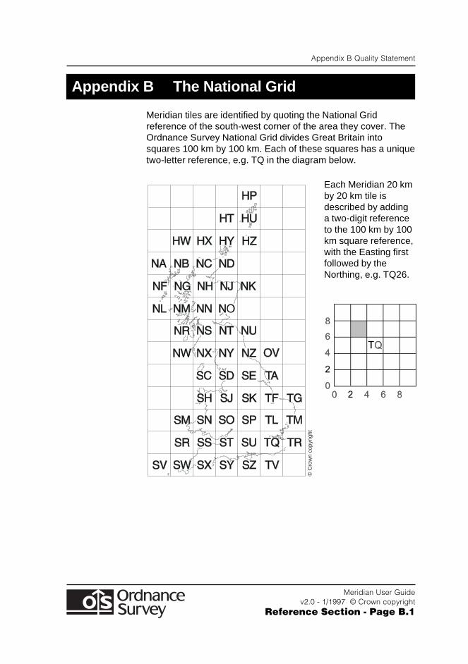
Meridian tiles are identified by quoting the National Gridreference of the south-west corner of the area they cover. TheOrdnance Survey National Grid divides Great Britain intosquares 100 km by 100 km. Each of these squares has a uniquetwo-letter reference, e.g. TQ in the diagram below.
Each Meridian 20 kmby 20 km tile isdescribed by addinga two-digit referenceto the 100 km by 100km square reference,with the Easting firstfollowed by theNorthing, e.g. TQ26.
©C
row
n co
pyrig
ht

Appendix B Quality Statement
Meridian User Guidev2.0 - 1/1997 © Crown copyright
Reference Section - Page B.2
Appendix C Glossary
Meridian User Guidev2.0 - 1/1997 © Crown copyright
Reference Section - Page C.1
Appendix C Glossary
AccuracyThe closeness of the results of observations, computations orestimates to the true values or the values accepted as beingtrue. Accuracy relates to the exactness of the result, and is theexactness of the operation by which the result is obtained.
Administrative AreaA blanket term used by Ordnance Survey to refer to all publicadministrative areas, specifically Local Governmentmanagement and electoral areas.
American Standard Code for Information Interchange(ASCII)A 7-bit code for encoding a standard character set.
AreaA spatial extent defined by circumscribing lines that form aclosed perimeter that does not intersect itself.
Area SeedA point within an area that can be used to carry the attributes ofthe whole area, e.g. ownership, address and use type.
Asset Management/Facilities Management (AM/FM)An American term for computerised information systemsinvolving digital mapping used by utilities, for example, tomanage their plant.
AttributeAn attribute is a property of an entity, usually used to refer to anon-spatial qualification of a spatially referenced entity. Forexample, a descriptive code indicating what an entityrepresents, or how it should be portrayed.
Attribute ClassA specific group of attributes, e.g. those describing measure,serviceability, structure, or composition.
Appendix C Glossary
Meridian User Guidev2.0 - 1/1997 © Crown copyright
Reference Section - Page C.2
Attribute CodeAn alphanumeric identifier for an attribute type.
Attribute ValueA specific quality or quantity assigned to an attribute.
Basic ScaleThe scale at which the survey is maintained. For OrdnanceSurvey mapping, three scales (1:1250, 1:2500, 1:10 000) areused. Any area is only maintained at one basic scale.
BearingBearings are angles measured against National Grid bearings indegrees. They are measured clockwise from Grid North.
BlockData on magnetic media may be recorded in blocks ofcharacters for more efficient movement within or betweencomputer systems. The length of the block will vary according tothe medium and the data transfer format used.
BoundaryA boundary is the limit of a predefined and established areawhose limit is determined by one or more Lines , e.g. Countyarea boundary and developed land use area boundary.
ByteA unit of computer storage of binary data usually comprising 8bits, equivalent to a character. Hence Megabyte (Mb) andGigabyte (Gb).
CADComputer Aided Design
CartographyThe organisation and communication of geographically relatedinformation in either graphic or digital form. It can include allstages from data acquisition to presentation and use.
CharacterA distinctive mark; an inscribed letter; one of a set of writing-symbols.
Appendix C Glossary
Meridian User Guidev2.0 - 1/1997 © Crown copyright
Reference Section - Page C.3
Character StringA one-dimensional array of charcters held either in memory or inanother storage medium.
CodingAllocation of a feature code to a feature being created fromconstituent construction data - points and/or segments; withoptional linking to an existing feature of the same feature code.
Compact Disc - Read Only Memory (CD-ROM)A data storage medium. A 12 cm disc similar to an audio CD.Ordnance Survey uses the Writable CD, a WORM (write onceread many) device. The digital ‘bits’ are encoded into avegetable dye and, once written, cannot be erased byoverwriting with subsequent data. The disc is read by laser.
Continuation MarkA logical record may contain more data than can be held in asingle physical record. The physical record contains acontinuation mark - the penultimate character of the record inNTF - to indicate whether more data is to be found in acontinuation record.
Continuation RecordA specific NTF term. A continuation record is used where spacedos not allow one logical record to be contained wholly withinone physical record.
Coordinate pairA coordinate pair is an Easting and a Northing.
CoordinatesPairs of numbers expressing horizontal distances along originalaxis. Alternatively triplets of numbers measuring horizontal andvertical distances. Row and column numbers of pixels from rawimagery are not considered coordinates for the purpose of thestandard.
Appendix C Glossary
Meridian User Guidev2.0 - 1/1997 © Crown copyright
Reference Section - Page C.4
CopyrightCopyright is a legal property right which enables the creator ofan original work to protect it from unauthorised use. Through the1988 Copyright, Designs and Patents Act , Crown copyrightcontinues to subsist in all Ordnance Survey products until theend of the period of 50 years from the end of the year in whichthey were published, and in the case of data from the end of theyear in which it was extracted from the Ordnance Surveydatabase. Crown copyright is vested in The Controller of HerMajesty’s Stationery Office, who has delegated powers to theDirector General, Ordnance Survey for the administration ofcopyright in publications and data, including the determination ofterms and conditions under which permission for theirreproduction is given.
CurrencyAn expression of the up-to-dateness of data.
DataA representation of facts, concepts or instructions in aformalised manner suitable for communication, interpretation orprocessing.
Data CaptureThe encoding of data. In the context of digital mapping, thisincludes map digitising, direct recording by electronic surveyinstruments and the encoding of text and attributes by whatevermeans.
Data FormatA specification that defines the order in which data is stored or adescription of the way data is held in a file or record.
Data ModelAn abstraction of the real world which incorporates only thoseproperties thought to be relevant to the application orapplications at hand. The data model would normally definespecific groups of entities and their attributes and therelationship between these entities. A data model is independentof a computer system and its associated data structures. A mapis one example of an analogue data model.

Appendix C Glossary
Meridian User Guidev2.0 - 1/1997 © Crown copyright
Reference Section - Page C.5
DatabaseAn organised, integrated collection of data stored so as to becapable of use in relevant applications, with the data beingaccessed by different logical paths. Theoretically it isapplication-independent, but in reality it is rarely so.
DatasetAn Ordnance Survey term for a named collection of logicallyrelated features arranged in a prescribed manner. For example,all water features. A dataset has more internal structure than alayer and is related to another dataset only by position.
DDSDigital Data Storage
DensityA measure of the number of units of data held on a stated lengthof storage surface. For example some magnetic tapes may berecorded at a density of 1600 bits per inch (bpi). Often referredto as packing density.
Detached PartA term appying to a part of a Local Government orParliamentary area which is completely surrounded by otherLocal Government or Parliamentary areas, and is not connectedto the ‘parent’ area by direct access on the ground.
DigitalData which is expressed as numbers (digits) in computerreadable form is said to be digital.
Digital MapAny map sold by Ordnance Survey or its agents in any form -i.e. on computer-readable media or as hard copy on paper/filmor microfilm - produced mainly, or wholly, using computerisedmeans.
Digital Map DataThe digital data required to represent a map. The data includesnot only map detail but also feature header data, map headerdata and management data.

Appendix C Glossary
Meridian User Guidev2.0 - 1/1997 © Crown copyright
Reference Section - Page C.6
DigitisingThe process of converting analogue maps and other sources toa computer readable form. This may be point digitising, wherepoints are only recorded when a button is pressed on a cursor,or stream digitising where points are recorded automatically atpreset intervals of either distance or time as the cursor is tracedalong a map feature.
Distinctive nameA text feature consisting of text string(s) which form(s) a propername.
DXF (Drawing Interchange File)A proprietary data format, devised by Autodesk, by which digitaldrawings may be transferred between users of CAD (ComputerAided Design) systems. DXF has become an industry standarddata format and is used for the transfer of some OrdnanceSurvey data products.
EastingsSee Rectangular Coordinates .
Edge MatchThe process of ensuring that data along the adjacent edges ofmap sheets, or some other unit of storage, matches in bothpositional and attribute terms.
EntitySomething about which data is stored in a databank ordatabase. For example, building, tree. The data may consist ofrelationships, attributes, positional and shape information, etc.Often synonymous with feature.
ExabyteThe propriety name for a high density ¼" cartridge tape that willhold up to 2.4 Gb of data. See Gigabyte .
Extended Binary Coded Decimal Interchange Code(EBDCDIC)An 8-bit character encoding scheme.
Appendix C Glossary
Meridian User Guidev2.0 - 1/1997 © Crown copyright
Reference Section - Page C.7
Extent of the Realm (EOR)The external bounding lines of Land-Line data is the Extent ofthe Realm. The Territorial Waters Jurisdiction Act 1878 and theTerritorial Waters Order in Council 1964 confirm that the Extentof the Realm of Great Britain as used by Ordnance Survey isproperly shown to the limit of Mean Low Water (Mean LowWater Springs in Scotland) for the time being (except whereextended by Parliament).
FeatureAn item of detail within a map which can be either a point/symbol, a line or text.
Feature Classification RecordA specific, named NTF record which lists the Feature Codes inuse in the current database.
Feature Code (FC)An alphanumeric attribute code used in digital map data todescribe each feature in terms of the object surveyed, itsrepresentation on the map, or both.
Feature Serial Number (FSN)A number used as a feature identifier usually allocated on asequential basis. For example, the order in which features aredigitised.
FieldA specific part of a record containing a unit of data, such as thedate of digitising. The unit of data may be a data element or adata item. In NTF, a field is a subdivision of of a physical record.Every field has a name and a predefined interpretation.
FileAn organised collection of related Records . The records on afile may be related by a specific purpose, Format or data source- the records may or may not be arranged in sequence. A filemay consist of records, fields, words, Bytes , Characters or bits.
Floppy DiscThese are a magnetic medium, generally used inmicrocomputers (PCs) and come in 5¼" and 3½" sizes.
Appendix C Glossary
Meridian User Guidev2.0 - 1/1997 © Crown copyright
Reference Section - Page C.8
FontThe style of text character used by a printer or plotter.
FormatThe specified arrangement of data. For example, the layout of aprinted document, the arrangement of the parts of a computerinstruction, the arrangement of data in a Record .
Geographical Information System (GIS)A system for capturing, storing, checking, integrating, analysingand displaying data that is spatially referenced to the Earth. Thisis normally considered to involve a spatially referencedcomputer Database and appropriate applications software.
Geometric StructureThe ground is modelled in the data as a series of lines andpoints.
Gigabyte (Gb)1,073,741,824 bytes; a measure of data storage capacity.
GridThe planimetric frame of reference. For example, the NationalGrid.
Hard CopyA print or plot of output data on paper or some other tangiblemedium.
JunctionA connection between two or more links at a common node.Junctions may be X-junctions or T-junctions.
Kilobyte (Kb)1024 bytes; a measure of data storage capacity.
LayerA subset of digital map data, selected on a basis other thanposition. For example, one layer might consist of all featuresrelating to roads, and another to railways.
Appendix C Glossary
Meridian User Guidev2.0 - 1/1997 © Crown copyright
Reference Section - Page C.9
LineA series of connected coordinated points forming a simplefeature with homogeneous attribution.
Line FeatureThe spatial abstraction of an object in one dimension. Lines mayintersect with other lines. They are defined as a series of two ormore coordinates and may be curved or straight. Curved linesconsist of a series of very short straight line segments. Linesmay be concurrent with other lines under certain conditions. Asan object abstraction a line has no width.
Line SegmentA vector connecting two coordinated points.
Linear FeatureMap feature in the form of a line, e.g. road centre-lines, that mayor may not represent a real-world feature.
LinkLinks are the representation of line features. They are made upof one or more consecutive, non-intersecting, link segments withcommon attributes, between two terminating nodes. Links haveno connection with other links except at the start or end viacommon (shared) terminating nodes (points). All links containtheir terminating coordinates. Links may form the boundaries ofpolygons and may be shared between polygons. See also Line .
Link and Node DataA form of vector data in which linear features are represented aslinks. Links are terminated where they intersect other links.These intersection points, and link ends, may carry nodeswhose feature records express the geometric relationshipsbetween links.
Link and Node StructureA data structure in which links and nodes are stored with cross-referencing.
Appendix C Glossary
Meridian User Guidev2.0 - 1/1997 © Crown copyright
Reference Section - Page C.10
Magnetic TapeThis is the traditional data storage and data transfer medium formainframe computers. It consists of ½" wide magnetic tape on aspool or reel - 2400' length is used by Ordnance Survey. Thetape is referred to as 9-Track; 9 bits representing eachcharacter are recorded across the tape and whole charactersare read as the tape passes the read-head.
MapThe representation on a flat surface of all or part of the earth’ssurface, intended to be communicated for a purpose orpurposes, transforming relevant geographic data into anend-product which is visual, digital or tactile.
Map GeneralisationA reduction in map detail, so that the information remains clearand uncluttered when map scale is reduced. May also involvere-sampling to larger spacing, and/or a reduction in the numberof points in a line.
Map HeaderData at the start of the digital map file describing that data. Itmay contain information on the source and history of thegeometric data within the map and the coordinate system in useas well as holding information essential to the management ofOrdnance Survey’s digital mapping system.
Map ScaleThe ratio between the extent of a feature on the map and itsextent on the ground, normally expressed as a representativefraction. e.g. 1:1250, 1:50 000.
Megabyte (Mb)1,048,576 bytes; a measure of data storage capacity.
Name or Text featureThe proper name or label of an object (real-world) or feature(object abstraction) consisting of one or more text strings. Aname position is defined by a coordinate pair.
Appendix C Glossary
Meridian User Guidev2.0 - 1/1997 © Crown copyright
Reference Section - Page C.11
National GridA unique referencing system which can be applied to allOrdnance Survey maps of Great Britain (GB) at all scales. It isbased on 100 km squares covering the whole of GB based on aTransverse Mercator Projection. It is used by Ordnance Surveyon all postwar mapping to provide an unambiguous spatialreference in GB for any place or entity whatever the map scale.
National Transfer Format (NTF)A format designed in 1988 specifically for the transfer of spatialinformation; it is published as British Standard BS 7567 and isadministered by the Association for Geographic Information. It isnow the standard transfer format for Ordnance Survey digitalmap data.
NodeAn object representation of a point which either does not formany part of a link (isolated node or polygon seed point); or is therepresentation of a point at the start or end of a link (terminatingnode). The position of a node is defined by a single coordinatepair - which is repeated within all links logically connected atthat node and/or containing it. A node is only deleted if the linkcontaining it as a terminating node is deleted.
NorthingsSee Rectangular Coordinates .
OrientationOrientation of a point or a text feature is measured in degreesanticlockwise from Grid East.
OriginThe zero point in a system of Rectangular Coordinates .
PackingSpaces used as fillers to complete a record or field.
Pecked LineA line drawn as a series of dashes.
Appendix C Glossary
Meridian User Guidev2.0 - 1/1997 © Crown copyright
Reference Section - Page C.12
Physical RecordA physical record may be fixed length containing 80 characters,or variable length containing up to 80 characters.
PointA zero-dimensional spatial abstraction of an object representedas a coordinate pair.
Point and Line DataA form of vector data designed for map production in which allmap features are designated as points, lines or text. Point andline data does not carry the topological relationships betweenfeatures.
Point FeatureA zero-dimensional spatial abstraction of an object with itsposition defined by a coordinate tuple. Points are representedby nodes which may be isolated or part of a link (terminating).Points may also be represented by symbols which may haveattributes such as rotation and size.
PolygonPolygons are a representation of areas. A polygon is defined asa closed line or perimeter completely enclosing a contiguousspace and made up of one or more links. At least one nodeoccurs on the perimeter of a polygon where the bounding linkcompletes the enclosure of the area. There may be many nodesconnecting the bounding links of a polygon. Links may beshared between polygons. Polygons may wholly contain otherpolygons, or be contained within other polygons. Each maycontain a single isolated node (seed point) which identifies thepolygon.
Polygon BoundaryThe link or links which enclose a polygon, projected into thehorizontal plane.
Polygon PointA polygon seed.
Polygon SeedSee Seed.
Appendix C Glossary
Meridian User Guidev2.0 - 1/1997 © Crown copyright
Reference Section - Page C.13
Positional AccuracyThe degree to which the coordinates define a point’s trueposition in the world, directly related to the spheroid/projectionon which the coordinate system is based.
PrecisionThe exactness with which a value is expressed, whether thevalue be right or wrong.
RecordA set of related data fields grouped for processing.
Recording FormatThe logical and/or physical levels of the protocol governing thelaying down of data on the physical transfer medium.
Rectangular CoordinatesAlso known as X-Y Coordinates and as Eastings andNorthings . These are two-dimensional coordinates whichmeasure the position of any point relative to an arbitrary originon a plane surface, e.g. a map projection, a digitising table, aVDU screen.
ResolutionA measure of the ability to detect quantities. High resolutionimplies a high degree of discrimination but has no implication asto Accuracy . For example, in a collection of data in which theCoordinates are rounded to the nearest metre, resolution willbe 1 m but the accuracy may be ±5 m or worse.
SectionIn NTF terminology, a subdivision of a database. In OrdnanceSurvey terms this equates to a single map sheet, i.e. a digitalmap file or a tile.
SeedA seed is a digitised point within an area, usually a definedpolygon, e.g. lake or woodland, but not always, e.g. ageographical seed, such as the South Downs.
Appendix C Glossary
Meridian User Guidev2.0 - 1/1997 © Crown copyright
Reference Section - Page C.14
Seed PointA coordinated point within a polygon to which alphanumericinformation may be attached.
SegmentA chord defined by two consecutive Coordinates in a linestring.
Source ScaleThe scale of the source information from which the map wasdigitised, i.e. the scale of survey for a Basic Scale Map, or thescale of the source map for a Derived Map.
Spatial DataData which includes a reference to a two- or three-dimensionalposition in space as one of its attributes. It is used as asynonym for geometric data.
Structured dataData within which collections of features - of any type - formobjects. Topographically structured data also containstopological information defining the relationships betweenfeatures and objects.
TerminatorA character, character string, field or record used to signal theend of a record, section, volume or database.
Text CoordinatesEach text feature has a ‘start-of-text’ coordinate which isdigitised.
Text FeatureA free standing text string in the digital data describing a feature,or particualr instance of a feature, e.g. Factory, Acacia Avenue.
Text HeightThe height at which a text string is intended to be plotted out atthe nominal map scale. This information is included in thefeature header of the text feature.
Appendix C Glossary
Meridian User Guidev2.0 - 1/1997 © Crown copyright
Reference Section - Page C.15
Text PositionSee Text Coordinates. Also known as Original DigitisingPosition.
TileBroadly synonymous with digital map file, it implies evenly sizedmap sheet units.
TK50A data cartridge for use with Digital Equipment Corporation(DEC) hardware.
Topographic DatabaseA database holding data relating to physical features andboundaries on the Earth’s surface.
TopographyTopography is the study of the physical features of the Earth. Atopographic map’s principal purpose is to portray and identifythe features of the Earth.
TopologyThe study of the properties of a geometric figure which are notdependent on position, such as connectivity and relationshipsbetween lines, nodes and polygons.
Transfer FormatThe format used to transfer data between computer systems. Ingeneral usage this can refer not only to the organisation of data,but also to the associated information, such as attribute codes,which are required in order to successfully complete thetransfer.
Transfer MediumThe physical medium on which digital data is transferred fromone computer system to another. For example, magnetic tape.
Transfer SetA specific NTF term for the data, together with its supportinginformation, which the customer receives.
Appendix C Glossary
Meridian User Guidev2.0 - 1/1997 © Crown copyright
Reference Section - Page C.16
UNIXAn operating system that supports multi-tasking and is used bymany workstations and minicomputers.
UpdateThe process of adding to and revising existing digital map datato take account of change.
VectorA straight line joining two data points.
Vector DataPositional data in the form of coordinates of the ends of linesegments, points, text positions, etc.
VolumeA physical unit of the transfer medium, that is, a single disc, asingle cartridge or a single tape.
Appendix D Terms and Conditions
Meridian User Guidev2.0 - 1/1997 © Crown copyright
Reference Section - Page D.1
Appendix D Terms and Conditions
The following give a brief guide to the terms and conditions ofsupply and use of Meridian. A full description is detailed in thesigned customer contract held by your organization.
Use of Meridian
Meridian is supplied under single payment license, valid for fiveyears and includes copyright royalties
The fee includes a customer-use factor (charge band) and theright to make up to 5 000 hard copies per year for agreedinternal business use.
Delivery of Meridian
Customers are advised to copy the supplied data to a back-upmedium.
Written notification of any deficiency in the data or damage tothe goods must be given to Ordnance Survey within 28 days ofreceipt of Meridian.
Invoice
Payment in full, of the amount shown on the invoice, is due 30days after the invoice date. The only exception is whereOrdnance Survey have agreed extended terms with a customer.
Appendix D Terms and Conditions
Meridian User Guidev2.0 - 1/1997 © Crown copyright
Reference Section - Page D.2
Copyright
All Ordnance Survey Digital Map Data are Crown copyright. Fulldetails of the conditions under which Ordnance Survey DigitalMap Data may be processed/manipulated or copied by acustomer – whether or not for use on visual terminals or formaking hard copies – are contained in Ordnance Survey leaflet:Copyright 3 - Digital Map Data. These are available fromCopyright, please see below. Users should check the terms andconditions with Ordnance Survey before using the data. It isalso the responsibility of the holder of the Digital Map Data toensure that any output contains the required copyrightacknowledgement.
No part of this document may be reproduced or transmitted inany form or by any means, electronic or mechanical, for anypurpose, without the express written permission of OrdnanceSurvey.
© Crown copyright Reserved
CopyrightOrdnance SurveyRomsey RoadSOUTHAMPTONSO16 4GU
Telephone 01703 792684Fax 01703 792535

Appendix E Product Performance Report Form
Meridian User Guidev2.0 - 1/1997 © Crown copyright
Reference Section - Page E.1
Appendix E Product Performance Report Form
Please photocopy and send completed to:
Ordnance SurveySenior Product Manager Meridian TeamRomsey RoadSOUTHAMPTONSO16 4GU
Problem description/suggestion for:
....................................................................................................
....................................................................................................
....................................................................................................
....................................................................................................
....................................................................................................
....................................................................................................
....................................................................................................
....................................................................................................
....................................................................................................
Quotation/Order Ref: ...........................................................
Your Name: ...........................................................
Company: ...........................................................
Address: ...........................................................
...........................................................
...........................................................
...........................................................
...........................................................
Tel: ....................................... Fax: .......................................

Appendix E Product Performance Report Form
Meridian User Guidev2.0 - 1/1997 © Crown copyright
Reference Section - Page E.2
Meridian Format Section
Meridian User Guidev2.0 - 1/1997 © Crown copyright
Format Section
MeridianUser Guide
Format Section

Meridian Format Section
Meridian User Guidev2.0 - 1/1997 © Crown copyright
Format Section
Chapter 1 Introduction
Meridian User Guidev2.0 - 1/1997 © Crown copyright
Format Section - Page 1.1
Chapter 1 Introduction
The purpose of this Format Section is to:
● Provide a brief description of the presentation of Meridian inthe two transfer formats in which it is supplied:
● BS 7567 (NTF v2.0 Level 3)● Drawing Interchange File (DXF) (conforming to AutoCAD
release 12 with Extended Entity Data)
As part of this description, Data Structure diagrams are usedto give greater explanation where necessary
● Provide Licenced System Suppliers with as much detail asnecessary to enable Meridian files in either NTF or DXF to beeasily understood and processed by application software.
The term ‘Data Structure’ used in this Format Section refers tothe organisation and sequence of the records in the data file andNOT to the geographical topology of the data.
Because of the fundamental differences in the data format ofStrategi supplied in NTF and DXF, this section devotes separatechapters to these transfer formats for the following aspects:
● General explanation of file format
● Data structure.
In other chapters where there is a need to be specific about oneformat the relevant text is highlighted. The following is anexample of the style used in these circumstances.
For convenience, BS 7567 (NTF v2.0 Level 3) isreferred to as NTF in this Section.
Drawing Interchange File (DXF) is referred to as DXFin this Section. Complies with BS 1192 Part 5 Guidefor structuring of computer graphic information.
This Section should be read in conjunction with the MeridianReference Section which describes the content of Meridian.
DXF
BS 7567
NTF
Chapter 1 Introduction
Meridian User Guidev2.0 - 1/1997 © Crown copyright
Format Section - Page 1.2
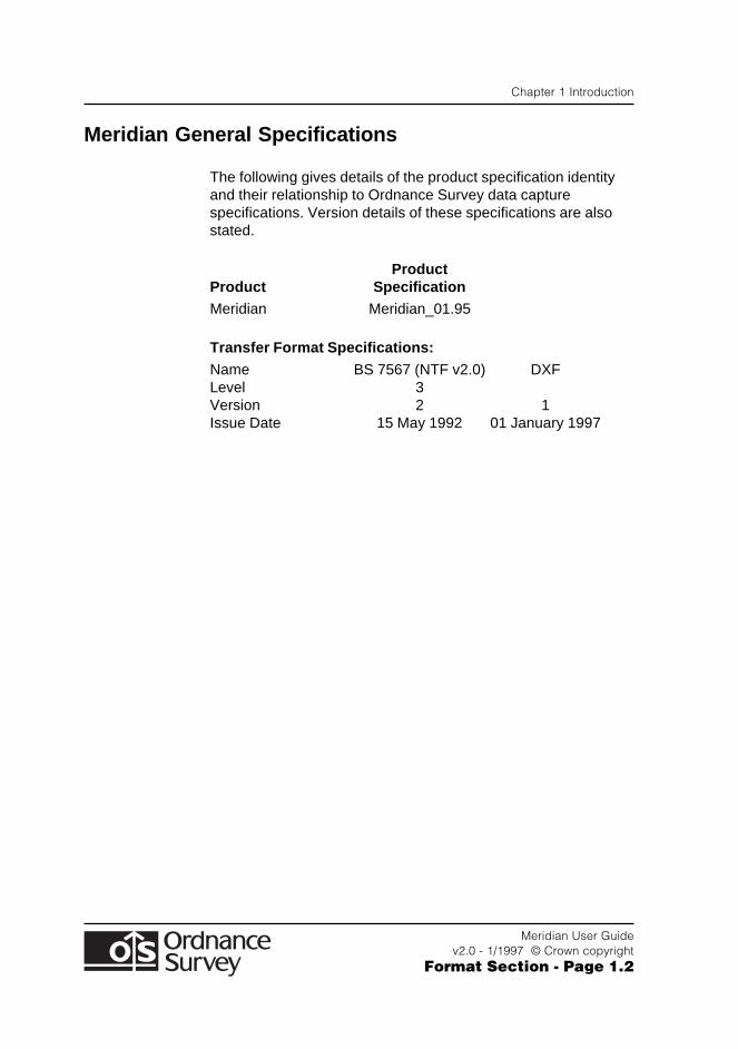
Meridian General Specifications
The following gives details of the product specification identityand their relationship to Ordnance Survey data capturespecifications. Version details of these specifications are alsostated.
ProductProduct SpecificationMeridian Meridian_01.95
Transfer Format Specifications:
Name BS 7567 (NTF v2.0) DXFLevel 3Version 2 1Issue Date 15 May 1992 01 January 1997
Chapter 2 Introduction to Data Formats
Meridian User Guidev2.0 - 1/1997 © Crown copyright
Format Section - Page 2.1
Chapter 2 Introduction to Data Formats
NTF
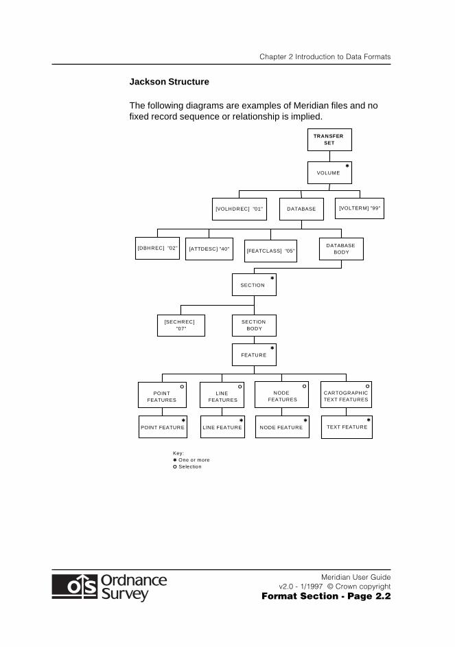
Data supplied in this format has variable length records. Anoverview of the data format of a Meridian file in NTF is shownover the page. The convention used for diagramming data filesis the industry standard adopted for Jackson StructuredProgramming (JSP).
Chapter 2 Introduction to Data Formats
Meridian User Guidev2.0 - 1/1997 © Crown copyright
Format Section - Page 2.2
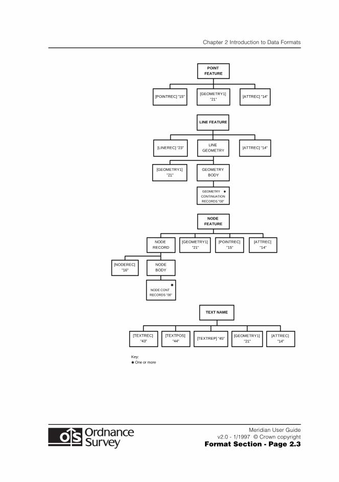
Jackson Structure
The following diagrams are examples of Meridian files and nofixed record sequence or relationship is implied.
✱
NODE FEATURE
✱
POINT FEATURE
✱
LINE FEATURE
O NODE
FEATURES
O LINE
FEATURES
✱
FEATURE
[SECHREC] "07"
SECTION BODY
✱
SECTION
DATABASE BODY[FEATCLASS] "05"[ATTDESC] "40"[DBHREC] "02"
[VOLTERM] "99"[VOLHDREC] "01" DATABASE
✱
VOLUME
TRANSFER SET
O POINT
FEATURES
O CARTOGRAPHIC TEXT FEATURES
✱
TEXT FEATURE
Key: ✱ One or more O Selection
Chapter 2 Introduction to Data Formats
Meridian User Guidev2.0 - 1/1997 © Crown copyright
Format Section - Page 2.3
[GEOMETRY1]
"21"[POINTREC] "15"
POINT FEATURE
[ATTREC] "14"
[TEXTREC]
"43"
[TEXTPOS]
"44"[TEXTREP] "45"
[GEOMETRY1]
"21"
[ATTREC]
"14"
LINE
GEOMETRY[LINEREC] "23"
LINE FEATURE
[ATTREC] "14"
[GEOMETRY1]
"21"
[ATTREC]
"14"
[GEOMETRY1]
"21"
GEOMETRY
BODY
GEOMETRY ✱
CONTINUATION
RECORDS "00"
NODE FEATURE
[POINTREC]
"15"
NODE
RECORD
TEXT NAME
✱
NODE CONT
RECORDS "00"
NODE
BODY
[NODEREC]
"16"
Key:
✱ One or more
Chapter 2 Introduction to Data Formats
Meridian User Guidev2.0 - 1/1997 © Crown copyright
Format Section - Page 2.4
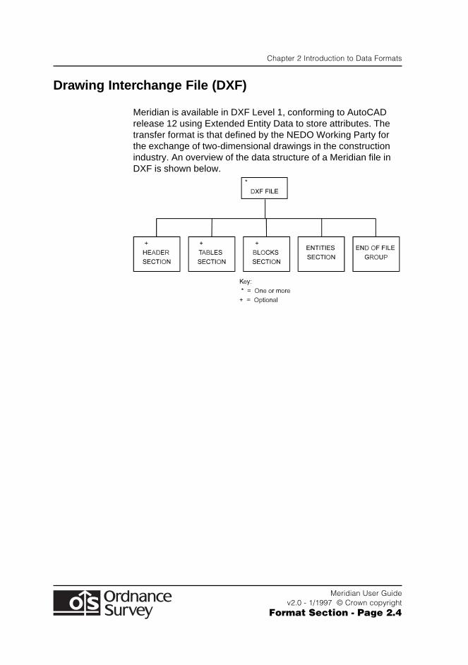
Drawing Interchange File (DXF)
Meridian is available in DXF Level 1, conforming to AutoCADrelease 12 using Extended Entity Data to store attributes. Thetransfer format is that defined by the NEDO Working Party forthe exchange of two-dimensional drawings in the constructionindustry. An overview of the data structure of a Meridian file inDXF is shown below.
Chapter 3 NTF Explained
Meridian User Guidev2.0 - 1/1997 © Crown copyright
Format Section - Page 3.1
Chapter 3 NTF Explained
Meridian data is supplied in the British Standard national formatcommon to all Ordnance Survey’s digital map data products;namely NTF, and is transferred in Level 3 as variable lengthrecords. An overview of the data structure of a Meridian data fileis shown in diagrammatic form in Chapter 2 of the FormatSection. The convention used for this diagram is in the industrystandard adopted for Jackson Structured Programming (JSP).
The British Standard for NTF stipulates the following for Level 3:This level supports a variety of data models that may includenetwork data, polygons, semantic relationships and complexfeatures - for example, a school consisting of its buildings,boundaries and playing fields.
This level is designed for:
● Transferring basic geometry and simple features through theuse of geometry and feature records
● Relating basic geometrical and topological elements to oneor more features through the use of chain, polygon andcomplex line records
● Combining features to form complex features through theuse of collection and complex polygon records
● Using text records both to relate text strings to features andcartographic output
● Referencing and positioning external features, for example,raster data.
The record structure at this level may also be defined to becompatible with data in Levels 1 and 2.
The colour and line weights of some layers may differ whenDXF is used with certain software packages.

Chapter 3 NTF Explained
Meridian User Guidev2.0 - 1/1997 © Crown copyright
Format Section - Page 3.2
The governing body for the industry standard NTF is theAssociation for Geographic Information (AGI).
Their address is as follows:
The Association for Geographic Informationc/o The Royal Institution of Chartered Surveyors12 Great George StreetParliament SquareLONDONSW1P 3AD
Telephone: 0171 222 7000
Any queries relating to the Meridian product should be referredto Customer Services - Digital Help Desk at the address given inContact Details at the beginning of this User Guide.
Chapter 4 DXF Explained
Meridian User Guidev2.0 - 10/1997 © Crown copyright
Format Section - Page 4.1
Chapter 4 DXF Explained
Introduction
This chapter describes the representation of Meridian inOrdnance Survey’s implementation of DXF. Meridian is suppliedto the Product Specification Meridian_01.95
Overview
Structure of Meridian
Meridian has a limited ‘Link and Node’ data structure; within thisstructure a feature may be a name, a point, or a line (or series oflines forming a coherent unit). Each feature is free standing; thatis, its topological relationship to any other feature is NOTexpressed in the data.
Features are classified by type and each type is placed in aseparate DXF layer.
Line Features
A feature is a subjective entity; that is, so long as the constituentlines are of the same description (layer), a feature need not fullydescribe a logical piece of detail.
The extent of a feature is determined by digitising conventionsand does not always coincide with the topology. Each linearfeature is composed of a string of XY coordinate pairs implicitlyjoined by straight lines.
The colour and line weights of some layers may differ whenDXF is used with certain software packages.
Chapter 4 DXF Explained
Meridian User Guidev2.0 - 1/1997 © Crown copyright
Format Section - Page 4.2
Area Features
Area features are not defined within vector link and node data.Features which might be thought of as area features are treatedin the data as linear features, e.g. a developed land use areaboundary is treated as a polyline in layer G8056300.
Name Features
Name features are treated as free standing text data. There isno explicit relationship (in the data) between a text feature andthe point or line feature to which it belongs.
Ordnance Survey distinguishes between layer name types, forexample Place Names and Station Names - by placing eachname type in a separate DXF layer.
Text has position, expressed as a single coordinate pair, held asX and Y offsets from the map origin (SW corner). Text which isdouble or treble banked is treated as two or three separatefeatures. The text string may be considered to be containedwithin an ‘envelope’ whose bottom left hand corner is positionedon this coordinate pair. Text is oriented, that is, it may run fromwest to east across the map, or it may be plotted at some otherangle measured anti-clockwise from grid east.
Chapter 4 DXF Explained
Meridian User Guidev2.0 - 10/1997 © Crown copyright
Format Section - Page 4.3
Drawing Content and Format
Coordinate System
The coordinate system is National Grid, (NG).
The NG coordinates are to a resolution of 0.01 metre. This is theresolution of the source data.
Height
No height attributes are applied to any feature.
Layer Names
British Standard 1192 Part 5, (Guide for structuring of computergraphic information) has been adopted.
Each layer name is an eight character string. The first fourcharacters relate to the AUG/Autodesk system, with G (GIS) asthe source of the information, and 800-899 as the part code.This product is G805.
The remaining four digits relate to existing Ordnance SurveyDigital Map Data in their own NTF system and are leading zerofilled.
For example:
G8056001 - Motorways
Neatline
Neatlines around the extent of the map data are added as linesin the ENTITIES section, (layer name G8050572).
Chapter 4 DXF Explained
Meridian User Guidev2.0 - 1/1997 © Crown copyright
Format Section - Page 4.4
Grid
A grid is added as lines in the ENTITIES section (layer nameG8050572). The grid is created by the translator and thereforemust be specified before the translation takes place.
Grid Values
Full 100 000 metre National Grid Easting and Northing valuesfollowed by an ‘m’ are added as text strings in the ENTITIESsection, (layer name G8050573) at each corner of the mapextent either horizontal or vertical to read from the lower leftcorner of the tile.
Intermediate grid values are shown as multiples of 1000 metresfrom the nearest 100 km National Grid, (layer name G8050572).These are horizontal.
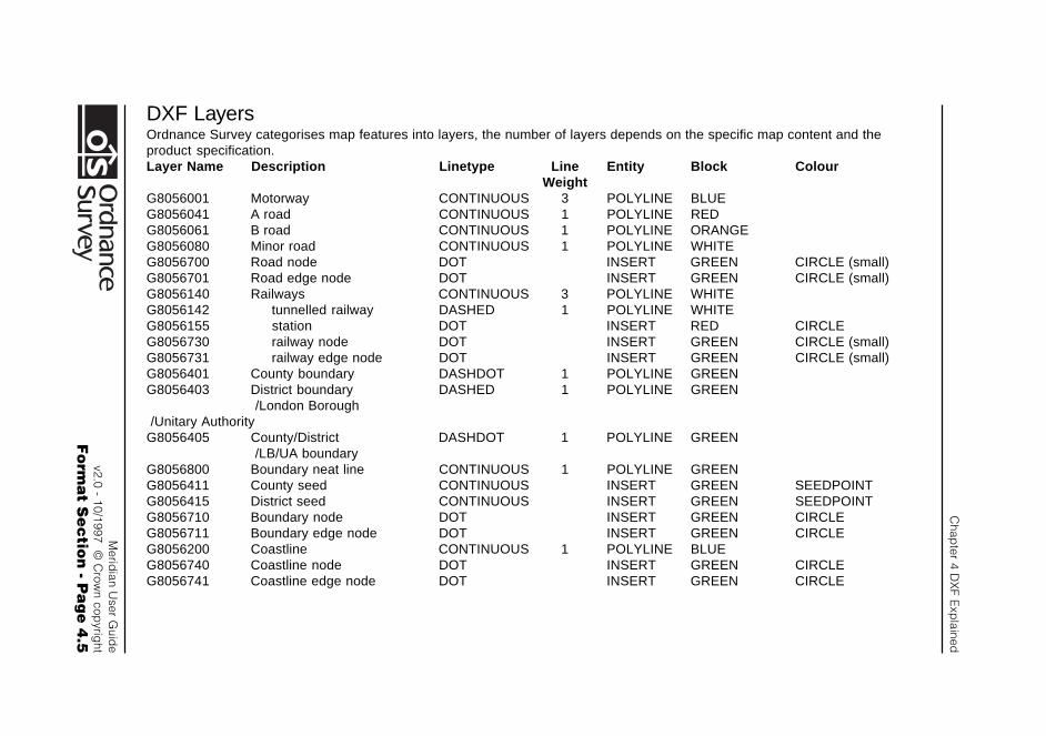
Chap
ter 4 DX
F Exp
lained
Merid
ian User G
uide
v2.0 - 10/1997 © C
rown cop
yright
Fo
rma
t Se
ctio
n - P
ag
e 4
.5
DXF LayersOrdnance Survey categorises map features into layers, the number of layers depends on the specific map content and theproduct specification.Layer Name Description Linetype Line Entity Block Colour
WeightG8056001 Motorway CONTINUOUS 3 POLYLINE BLUEG8056041 A road CONTINUOUS 1 POLYLINE REDG8056061 B road CONTINUOUS 1 POLYLINE ORANGEG8056080 Minor road CONTINUOUS 1 POLYLINE WHITEG8056700 Road node DOT INSERT GREEN CIRCLE (small)G8056701 Road edge node DOT INSERT GREEN CIRCLE (small)G8056140 Railways CONTINUOUS 3 POLYLINE WHITEG8056142 tunnelled railway DASHED 1 POLYLINE WHITEG8056155 station DOT INSERT RED CIRCLEG8056730 railway node DOT INSERT GREEN CIRCLE (small)G8056731 railway edge node DOT INSERT GREEN CIRCLE (small)G8056401 County boundary DASHDOT 1 POLYLINE GREENG8056403 District boundary DASHED 1 POLYLINE GREEN
/London Borough /Unitary AuthorityG8056405 County/District DASHDOT 1 POLYLINE GREEN
/LB/UA boundaryG8056800 Boundary neat line CONTINUOUS 1 POLYLINE GREENG8056411 County seed CONTINUOUS INSERT GREEN SEEDPOINTG8056415 District seed CONTINUOUS INSERT GREEN SEEDPOINTG8056710 Boundary node DOT INSERT GREEN CIRCLEG8056711 Boundary edge node DOT INSERT GREEN CIRCLEG8056200 Coastline CONTINUOUS 1 POLYLINE BLUEG8056740 Coastline node DOT INSERT GREEN CIRCLEG8056741 Coastline edge node DOT INSERT GREEN CIRCLE
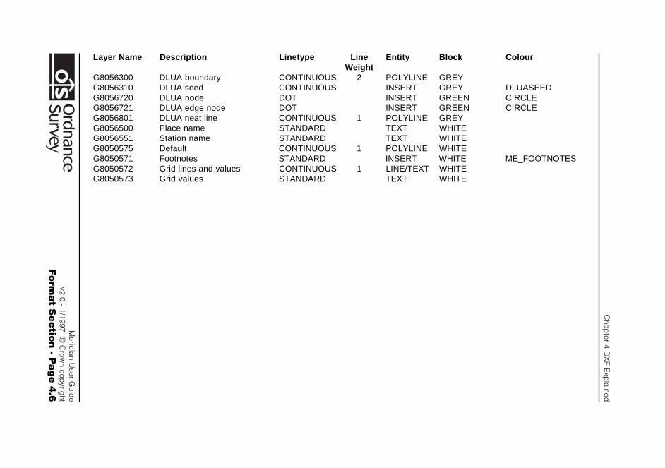
Chap
ter 4 DX
F Exp
lained
Merid
ian User G
uide
v2.0 - 1/1997 © C
rown cop
yright
Fo
rma
t Se
ctio
n - P
ag
e 4
.6
Layer Name Description Linetype Line Entity Block ColourWeight
G8056300 DLUA boundary CONTINUOUS 2 POLYLINE GREYG8056310 DLUA seed CONTINUOUS INSERT GREY DLUASEEDG8056720 DLUA node DOT INSERT GREEN CIRCLEG8056721 DLUA edge node DOT INSERT GREEN CIRCLEG8056801 DLUA neat line CONTINUOUS 1 POLYLINE GREYG8056500 Place name STANDARD TEXT WHITEG8056551 Station name STANDARD TEXT WHITEG8050575 Default CONTINUOUS 1 POLYLINE WHITEG8050571 Footnotes STANDARD INSERT WHITE ME_FOOTNOTESG8050572 Grid lines and values CONTINUOUS 1 LINE/TEXT WHITEG8050573 Grid values STANDARD TEXT WHITE
Chapter 4 DXF Explained
Meridian User Guidev2.0 - 10/1997 © Crown copyright
Format Section - Page 4.7
Footnotes
The following footnotes are added as an insert BLOCK in theENTITIES section of the DXF data file. The positions of thefootnotes are indicated in Figure 4.1.
Note 1: Top Margin centrally aligned, 700 ground metres,Layer: G8050571
Ordnance Survey ®
Note 2: Top Margin centrally aligned, 600 ground metres,Layer: G8050571
Meridian ™ Data
Note 3: Lower left margin, 200 ground metres,Layer: G8050571
Translation Date dd Mmmmmmmmm CCYY
Note 4: Lower left margin, 200 ground metres,Layer: G8050571
Tile reference number __ __ __
Note 5: Lower left margin, 200 ground metres,Layer: G8050571
Reproduced from Ordnance Survey Meridian ™ data withthe permission of the controller of Her Majesty’sStationary Office.
© Crown Copyright CCYY
Note 6: Lower right margin, 200 ground metres,Layer: G8050571
The derived scale of the product is dependent uponthe source data.
Note 7: Lower right margin, 200 ground metres,Layer: G8050571
The representation of a road, track or path is noevidence of a right of way.
The alignment of tunnels is approximate.
Note 8: Lower right margin, 200 ground metres,Layer: G8050571
Date of last amendment dd Mmmmmmmmm CCYY
Note 9: Lower right margin, 200 ground metres,Layer: G8050571
Product specification Meridian_01.96
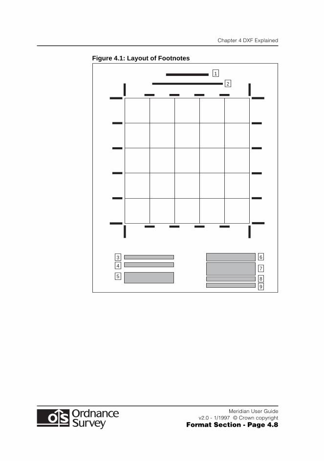
Chapter 4 DXF Explained
Meridian User Guidev2.0 - 1/1997 © Crown copyright
Format Section - Page 4.8
Figure 4.1: Layout of Footnotes
6
7
8
9
3
4
5
1
2
Appendix A NTF File Structure for Meridian
Meridian User Guidev2.0 - 1/1997 © Crown copyright
Format Section - Page A.1
Appendix A NTF File Structure for Meridian
An Overview of the Data in NTF
The following section gives a detailed breakdown of the datastructure of Meridian in NTF.
This is a two stage procedure which consists of:
1. Outline description of the data structure
2. Record breakdown.
There are certain conventions used in the record examples,which are:
[ ] Square brackets are placed around record names, e.g.[VOLHDREC].
{ } A pair of braces denote field names, e.g. {REC_DESC} isthe Record Descriptor Field.
[ ] 90 A two-digit number following square brackets denotes theRecord Descriptor which uniquely identifies the recordname between the brackets.
<S> This is the space character (ASCII code 32).
<3S> This denotes three successive space characters.
% The percentage character (ASCII code 37).
Appendix A NTF File Structure for Meridian
Meridian User Guidev2.0 - 1/1997 © Crown copyright
Format Section - Page A.2
Outline Description of the Data Structure
Record Size
NTF data is written to the output device in variable lengthrecords, with a maximum record length of 80 characters, whichincludes {CONT_MARK} and {EOR}.
Record Terminator {EOR}
The end of record terminator is the percent (%) (ASCII 37)character for both formatted and unformatted media.
Transfer Set
A transfer set normally equates to a single file except wherecontinuation volumes are used when the transfer set exceedsthe capacity of the media. The data the customer receives is inone or more Transfer Sets. Each Transfer Set starts with aVolume Header Record [VOLHDREC] and terminates with aVolume Terminator Record [VOLTERM].
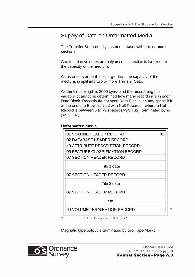
Appendix A NTF File Structure for Meridian
Meridian User Guidev2.0 - 1/1997 © Crown copyright
Format Section - Page A.3
Supply of Data on Unformatted Media
The Transfer Set normally has one dataset with one or moresections.
Continuation volumes are only used if a section is larger thanthe capacity of the medium.
A customer’s order that is larger than the capacity of themedium, is split into two or more Transfer Sets.
As the block length is 2000 bytes and the record length isvariable it cannot be determined how many records are in eachData Block. Records do not span Data Blocks, so any space leftat the end of a Block is filled with Null Records - where a NullRecord is between 0 to 79 spaces (ASCII 32), terminated by %(ASCII 37).
Unformatted media
01 VOLUME HEADER RECORD 01
02 DATABASE HEADER RECORD
40 ATTRIBUTE DESCRIPTION RECORD
05 FEATURE CLASSIFICATION RECORD
07 SECTION HEADER RECORD
Tile 1 data
07 SECTION HEADER RECORD
Tile 2 data
07 SECTION HEADER RECORD
etc.
99 VOLUME TERMINATION RECORD *
* ’99End Of Transfer Set 0%’
Magnetic tape output is terminated by two Tape Marks.
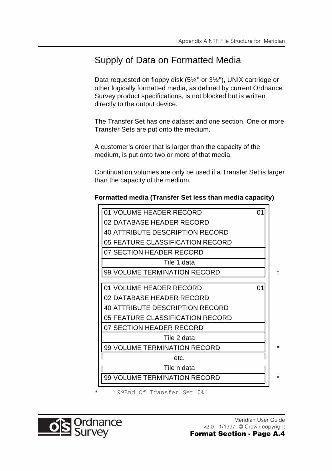
Appendix A NTF File Structure for Meridian
Meridian User Guidev2.0 - 1/1997 © Crown copyright
Format Section - Page A.4
Supply of Data on Formatted Media
Data requested on floppy disk (5¼" or 3½"), UNIX cartridge orother logically formatted media, as defined by current OrdnanceSurvey product specifications, is not blocked but is writtendirectly to the output device.
The Transfer Set has one dataset and one section. One or moreTransfer Sets are put onto the medium.
A customer’s order that is larger than the capacity of themedium, is put onto two or more of that media.
Continuation volumes are only be used if a Transfer Set is largerthan the capacity of the medium.
Formatted media (Transfer Set less than media capacity)
01 VOLUME HEADER RECORD 01
02 DATABASE HEADER RECORD
40 ATTRIBUTE DESCRIPTION RECORD
05 FEATURE CLASSIFICATION RECORD
07 SECTION HEADER RECORD
Tile 1 data
99 VOLUME TERMINATION RECORD *
01 VOLUME HEADER RECORD 01
02 DATABASE HEADER RECORD
40 ATTRIBUTE DESCRIPTION RECORD
05 FEATURE CLASSIFICATION RECORD
07 SECTION HEADER RECORD
Tile 2 data
99 VOLUME TERMINATION RECORD *
etc.
Tile n data
99 VOLUME TERMINATION RECORD *
* ’99End Of Transfer Set 0%’
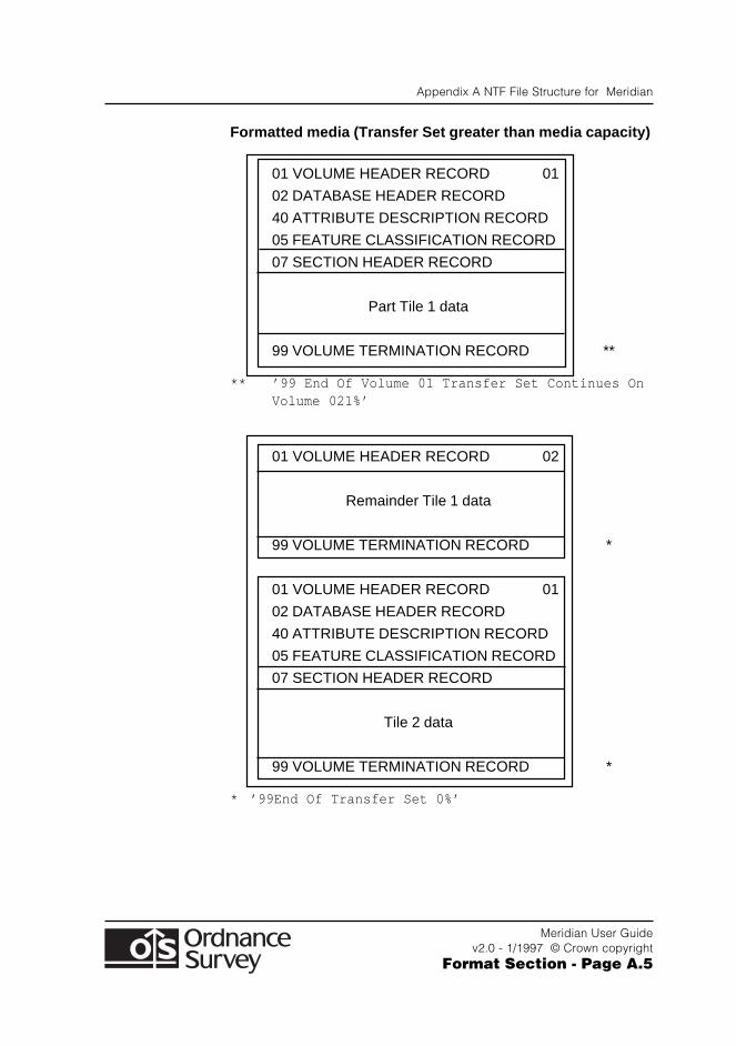
Appendix A NTF File Structure for Meridian
Meridian User Guidev2.0 - 1/1997 © Crown copyright
Format Section - Page A.5
Formatted media (Transfer Set greater than media capacity)
01 VOLUME HEADER RECORD 01
02 DATABASE HEADER RECORD
40 ATTRIBUTE DESCRIPTION RECORD
05 FEATURE CLASSIFICATION RECORD
07 SECTION HEADER RECORD
Part Tile 1 data
99 VOLUME TERMINATION RECORD **
** ’99 End Of Volume 01 Transfer Set Continues OnVolume 021%’
01 VOLUME HEADER RECORD 02
Remainder Tile 1 data
99 VOLUME TERMINATION RECORD *
01 VOLUME HEADER RECORD 01
02 DATABASE HEADER RECORD
40 ATTRIBUTE DESCRIPTION RECORD
05 FEATURE CLASSIFICATION RECORD
07 SECTION HEADER RECORD
Tile 2 data
99 VOLUME TERMINATION RECORD *
* ’99End Of Transfer Set 0%’
Appendix A NTF File Structure for Meridian
Meridian User Guidev2.0 - 1/1997 © Crown copyright
Format Section - Page A.6
The beginning of each Transfer Set is structured with thefollowing ‘introductory’, or ‘leading’, records:
Database Header Record [DBHREC]: this gives details of:
1. The Database Name
2. NTF Release Date
3. Feature Classification Table Name
4. Release date which applies to the whole of theTransfer Set.
Attribute Description Record [ATTDESC]: this lists andgives a description of the Attributes that can be applied tofeatures within the Transfer Set.
Feature Classification Record [FEATCLASS]: this listsand gives descriptions of all possible Feature Codes for theTransfer Set.
These ‘introductory’ records are followed by the data requestedby the customer, which are contained in the section.
The section consists of two parts:
1. Section Header Record [SECHREC]: this gives theNational Grid coordinates of the section and on unformattedmedia informs the customer that a new section is starting.
2. Section Body: this comprises all the features within thesection.
Appendix A NTF File Structure for Meridian
Meridian User Guidev2.0 - 1/1997 © Crown copyright
Format Section - Page A.7
Version Management
Each version and release of all Meridian products are defined bya unique Product Version number and Release number - theseare reflected in this User Guide. The Product Version numberrelates to the specification of the data being supplied, and theRelease number relates to the release of the product.
The Product Version number takes the form xx.yy , where xxis the major product number, and yy is the minor changenumber. Thus version 02.04 would indicate that this is the majorproduct version 02, and that this is the fourth minor amendmentto the product specification.
The Release number takes the form xx.yy , where xx is thesequential release within a year, and yy is the year of therelease. Thus release 02.94 would indicate that this is thesecond data release in 1994.
The Product Version number and the Release number arespecified in the Database Header Record [DBHREC], assupplied in NTF.
General
The following are the Record definitions for the transfer ofMeridian data in NTF:
● Volume Header Record [VOLHDREC]
● Database Header Record [DBHREC]
● Feature Classification Record [FEATCLASS]
● Attribute Description Record [ATTDESC]
● Section Header Record [SECHREC]
● Section Body - see Point and Line Features
● Name Detail
● Node Detail
● Volume Terminator Record [VOLTERM]
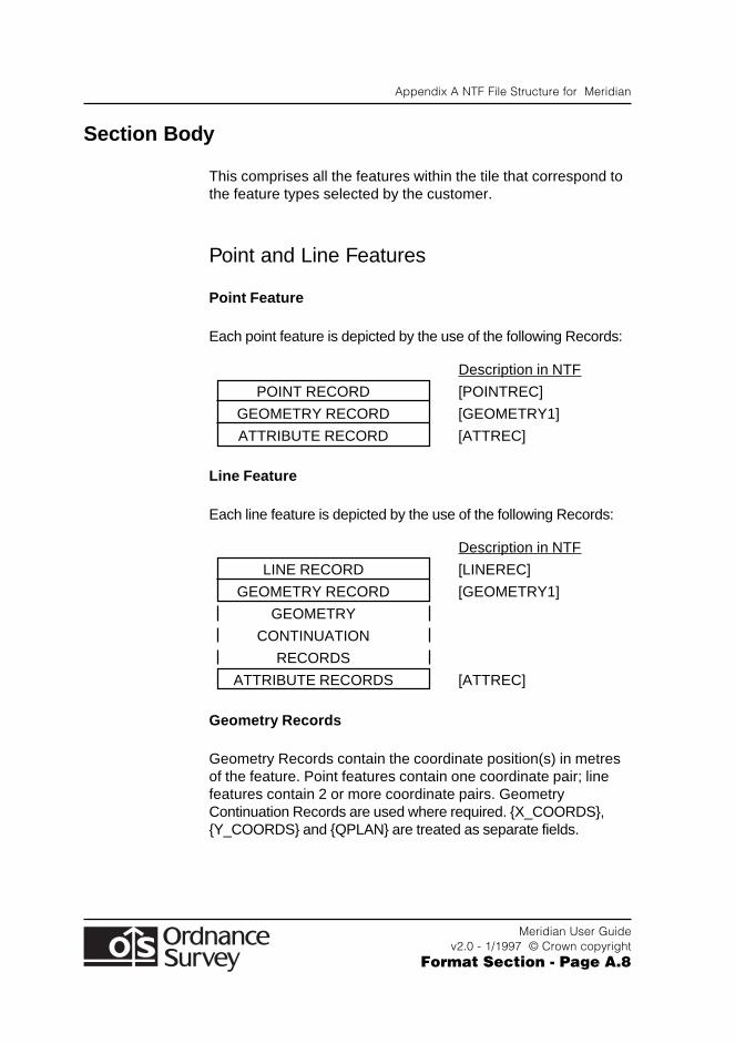
Appendix A NTF File Structure for Meridian
Meridian User Guidev2.0 - 1/1997 © Crown copyright
Format Section - Page A.8
Section Body
This comprises all the features within the tile that correspond tothe feature types selected by the customer.
Point and Line Features
Point Feature
Each point feature is depicted by the use of the following Records:
Description in NTF
POINT RECORD [POINTREC]
GEOMETRY RECORD [GEOMETRY1]
ATTRIBUTE RECORD [ATTREC]
Line Feature
Each line feature is depicted by the use of the following Records:
Description in NTF
LINE RECORD [LINEREC]
GEOMETRY RECORD [GEOMETRY1]
GEOMETRY
CONTINUATION
RECORDS
ATTRIBUTE RECORDS [ATTREC]
Geometry Records
Geometry Records contain the coordinate position(s) in metresof the feature. Point features contain one coordinate pair; linefeatures contain 2 or more coordinate pairs. GeometryContinuation Records are used where required. {X_COORDS},{Y_COORDS} and {QPLAN} are treated as separate fields.
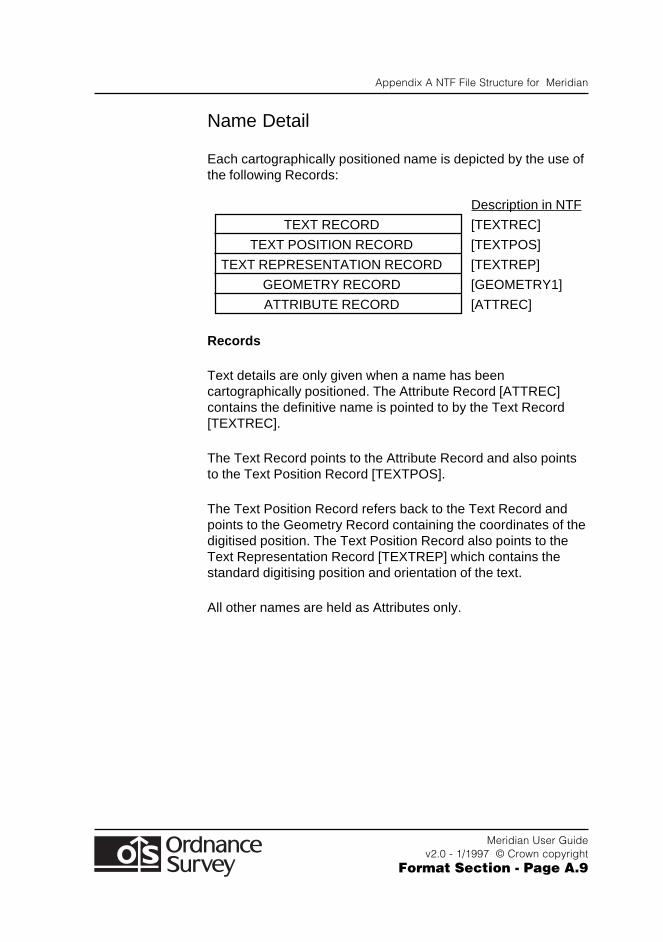
Appendix A NTF File Structure for Meridian
Meridian User Guidev2.0 - 1/1997 © Crown copyright
Format Section - Page A.9
Name Detail
Each cartographically positioned name is depicted by the use ofthe following Records:
Description in NTF
TEXT RECORD [TEXTREC]
TEXT POSITION RECORD [TEXTPOS]
TEXT REPRESENTATION RECORD [TEXTREP]
GEOMETRY RECORD [GEOMETRY1]
ATTRIBUTE RECORD [ATTREC]
Records
Text details are only given when a name has beencartographically positioned. The Attribute Record [ATTREC]contains the definitive name is pointed to by the Text Record[TEXTREC].
The Text Record points to the Attribute Record and also pointsto the Text Position Record [TEXTPOS].
The Text Position Record refers back to the Text Record andpoints to the Geometry Record containing the coordinates of thedigitised position. The Text Position Record also points to theText Representation Record [TEXTREP] which contains thestandard digitising position and orientation of the text.
All other names are held as Attributes only.
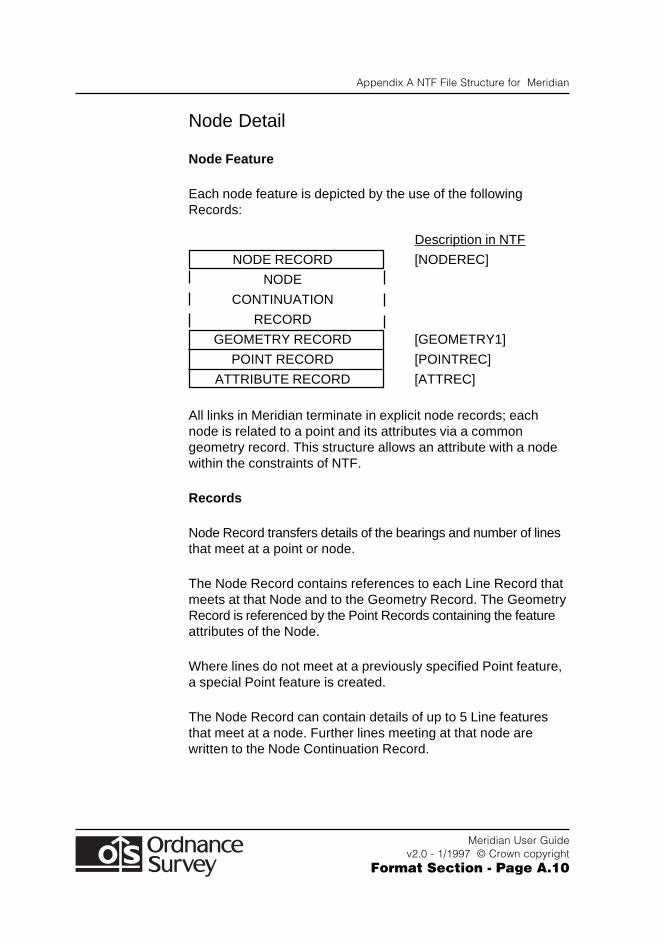
Appendix A NTF File Structure for Meridian
Meridian User Guidev2.0 - 1/1997 © Crown copyright
Format Section - Page A.10
Node Detail
Node Feature
Each node feature is depicted by the use of the followingRecords:
Description in NTF
NODE RECORD [NODEREC]
NODE
CONTINUATION
RECORD
GEOMETRY RECORD [GEOMETRY1]
POINT RECORD [POINTREC]
ATTRIBUTE RECORD [ATTREC]
All links in Meridian terminate in explicit node records; eachnode is related to a point and its attributes via a commongeometry record. This structure allows an attribute with a nodewithin the constraints of NTF.
Records
Node Record transfers details of the bearings and number of linesthat meet at a point or node.
The Node Record contains references to each Line Record thatmeets at that Node and to the Geometry Record. The GeometryRecord is referenced by the Point Records containing the featureattributes of the Node.
Where lines do not meet at a previously specified Point feature,a special Point feature is created.
The Node Record can contain details of up to 5 Line featuresthat meet at a node. Further lines meeting at that node arewritten to the Node Continuation Record.
Appendix A NTF File Structure for Meridian
Meridian User Guidev2.0 - 1/1997 © Crown copyright
Format Section - Page A.11
It is important to note that, although the Node Record containsreferences to its appropriate Point and Line features, the Pointand Line features do not contain references to the Node.
Feature Information Relevant to NTF
Point Features
Point features can exist independently and at the junction orends of lines. The point feature gives a position and attribute tothe corresponding node.
Line Features
All line features, with the exception of where railways cross atdifferent levels, are broken when they intersect one anotherwithin a layer. Note: a layer is a subset of digital map data,selected on a basis other than position. For example, one layermight consist of all features relating to roads, and another torailways.
The first and last coordinate pairs in a line correspond exactlywith the start or end coordinates of any adjoining line(s).
A line cannot cross from one tile (20 km by 20 km square) to thenext - it is split on the tile edge, but see Unique Identifiers.
All linear features are continuous. Cartographic gaps are closedduring the digitising process.
Appendix A NTF File Structure for Meridian
Meridian User Guidev2.0 - 1/1997 © Crown copyright
Format Section - Page A.12
Coordinates
Coordinate values and the number of coordinate pairs in afeature are transferred in the [GEOMETRY1] NTF record.
All coordinates within the data are expressed as strings of fivenumeric characters. Leading zeros are present to complete thefive characters.
All coordinates are measured from the local origin, which is thesouth-west corner of the tile.
To convert coordinate data to full National Grid coordinates, addthe coordinates of the feature to those of the south-west cornerof the tile. The south-west corner coordinates are containedwithin the {X_ORIG} and {Y_ORIG} fields of the Section HeaderRecord ([SECHREC] ‘07’).
Bearings
Bearings are transferred in the {ORIENT} field of the NodeRecord ([NODEREC] ‘16’).
Bearings are National Grid Bearings, in degrees, measuredclockwise from Grid North.
The start of line bearing, indicated by a value of ‘1’ in the {DIR}field of [NODEREC], is the bearing of the first segment of theline. The direction is from the start of the line to the next pair ofcoordinates or, if there are only two coordinate pairs, from thestart to the end of the line.
The end of line bearing, indicated by a ‘2’ in the {DIR} field, isthe bearing of the last segment of the line. The direction is fromthe end of the feature to the last-minus-one pair of coordinates.
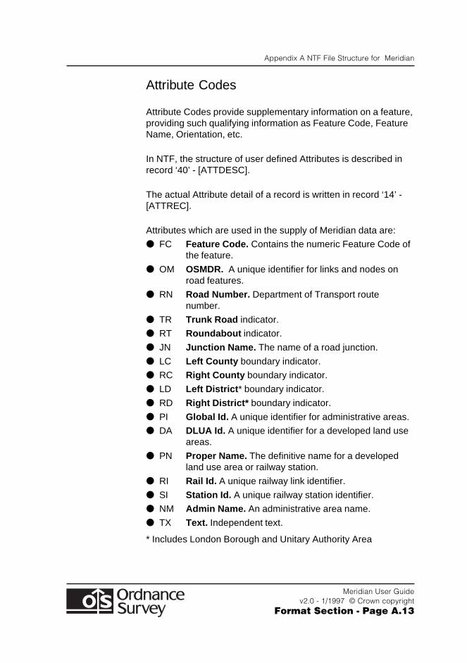
Appendix A NTF File Structure for Meridian
Meridian User Guidev2.0 - 1/1997 © Crown copyright
Format Section - Page A.13
Attribute Codes
Attribute Codes provide supplementary information on a feature,providing such qualifying information as Feature Code, FeatureName, Orientation, etc.
In NTF, the structure of user defined Attributes is described inrecord ‘40’ - [ATTDESC].
The actual Attribute detail of a record is written in record ‘14’ -[ATTREC].
Attributes which are used in the supply of Meridian data are:
● FC Feature Code. Contains the numeric Feature Code ofthe feature.
● OM OSMDR. A unique identifier for links and nodes onroad features.
● RN Road Number. Department of Transport routenumber.
● TR Trunk Road indicator.
● RT Roundabout indicator.
● JN Junction Name. The name of a road junction.
● LC Left County boundary indicator.
● RC Right County boundary indicator.
● LD Left District * boundary indicator.
● RD Right District* boundary indicator.
● PI Global Id. A unique identifier for administrative areas.
● DA DLUA Id. A unique identifier for a developed land useareas.
● PN Proper Name. The definitive name for a developedland use area or railway station.
● RI Rail Id. A unique railway link identifier.
● SI Station Id. A unique railway station identifier.
● NM Admin Name. An administrative area name.
● TX Text. Independent text.
* Includes London Borough and Unitary Authority Area
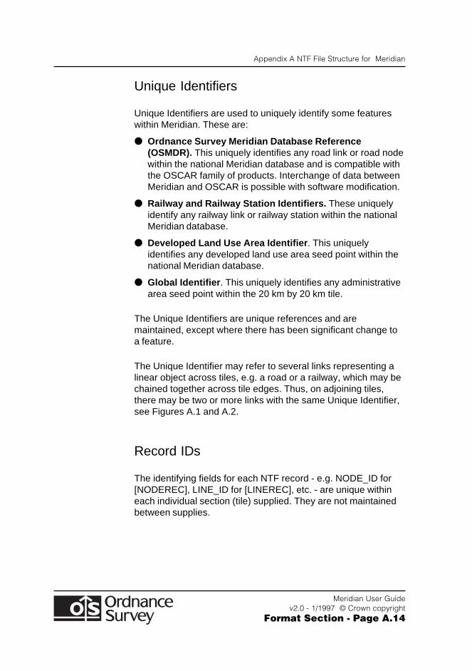
Appendix A NTF File Structure for Meridian
Meridian User Guidev2.0 - 1/1997 © Crown copyright
Format Section - Page A.14
Unique Identifiers
Unique Identifiers are used to uniquely identify some featureswithin Meridian. These are:
● Ordnance Survey Meridian Database Reference(OSMDR). This uniquely identifies any road link or road nodewithin the national Meridian database and is compatible withthe OSCAR family of products. Interchange of data betweenMeridian and OSCAR is possible with software modification.
● Railway and Railway Station Identifiers. These uniquelyidentify any railway link or railway station within the nationalMeridian database.
● Developed Land Use Area Identifier . This uniquelyidentifies any developed land use area seed point within thenational Meridian database.
● Global Identifier . This uniquely identifies any administrativearea seed point within the 20 km by 20 km tile.
The Unique Identifiers are unique references and aremaintained, except where there has been significant change toa feature.
The Unique Identifier may refer to several links representing alinear object across tiles, e.g. a road or a railway, which may bechained together across tile edges. Thus, on adjoining tiles,there may be two or more links with the same Unique Identifier,see Figures A.1 and A.2.
Record IDs
The identifying fields for each NTF record - e.g. NODE_ID for[NODEREC], LINE_ID for [LINEREC], etc. - are unique withineach individual section (tile) supplied. They are not maintainedbetween supplies.
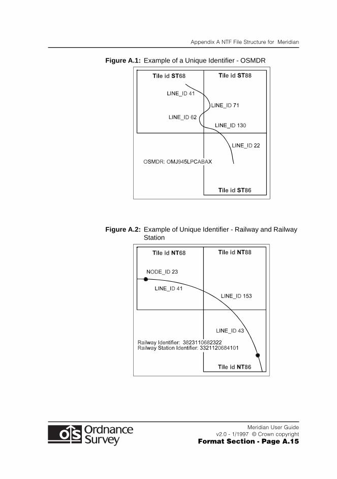
Appendix A NTF File Structure for Meridian
Meridian User Guidev2.0 - 1/1997 © Crown copyright
Format Section - Page A.15
Figure A.1: Example of a Unique Identifier - OSMDR
Figure A.2: Example of Unique Identifier - Railway and RailwayStation
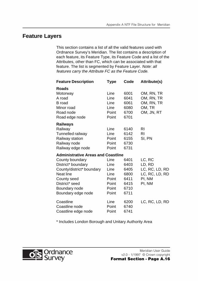
Appendix A NTF File Structure for Meridian
Meridian User Guidev2.0 - 1/1997 © Crown copyright
Format Section - Page A.16
Feature Layers
This section contains a list of all the valid features used withOrdnance Survey’s Meridian. The list contains a description ofeach feature, its Feature Type, its Feature Code and a list of theAttributes, other than FC, which can be associated with thatfeature. The list is segmented by Feature Layer. Note: allfeatures carry the Attribute FC as the Feature Code.
Feature Description Type Code Attribute(s)
RoadsMotorway Line 6001 OM, RN, TRA road Line 6041 OM, RN, TRB road Line 6061 OM, RN, TRMinor road Line 6080 OM, TRRoad node Point 6700 OM, JN, RTRoad edge node Point 6701
RailwaysRailway Line 6140 RITunnelled railway Line 6142 RIRailway station Point 6155 SI, PNRailway node Point 6730Railway edge node Point 6731
Administrative Areas and CoastlineCounty boundary Line 6401 LC, RCDistrict* boundary Line 6403 LD, RDCounty/district* boundary Line 6405 LC, RC, LD, RDNeat line Line 6800 LC, RC, LD, RDCounty seed Point 6411 PI, NMDistrict* seed Point 6415 PI, NMBoundary node Point 6710Boundary edge node Point 6711
Coastline Line 6200 LC, RC, LD, RDCoastline node Point 6740Coastline edge node Point 6741
* Includes London Borough and Unitary Authority Area
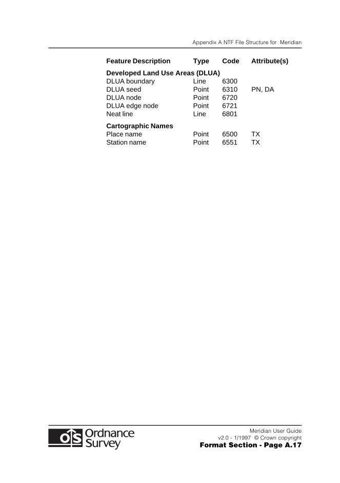
Appendix A NTF File Structure for Meridian
Meridian User Guidev2.0 - 1/1997 © Crown copyright
Format Section - Page A.17
Feature Description Type Code Attribute(s)
Developed Land Use Areas (DLUA)DLUA boundary Line 6300DLUA seed Point 6310 PN, DADLUA node Point 6720DLUA edge node Point 6721Neat line Line 6801
Cartographic NamesPlace name Point 6500 TXStation name Point 6551 TX
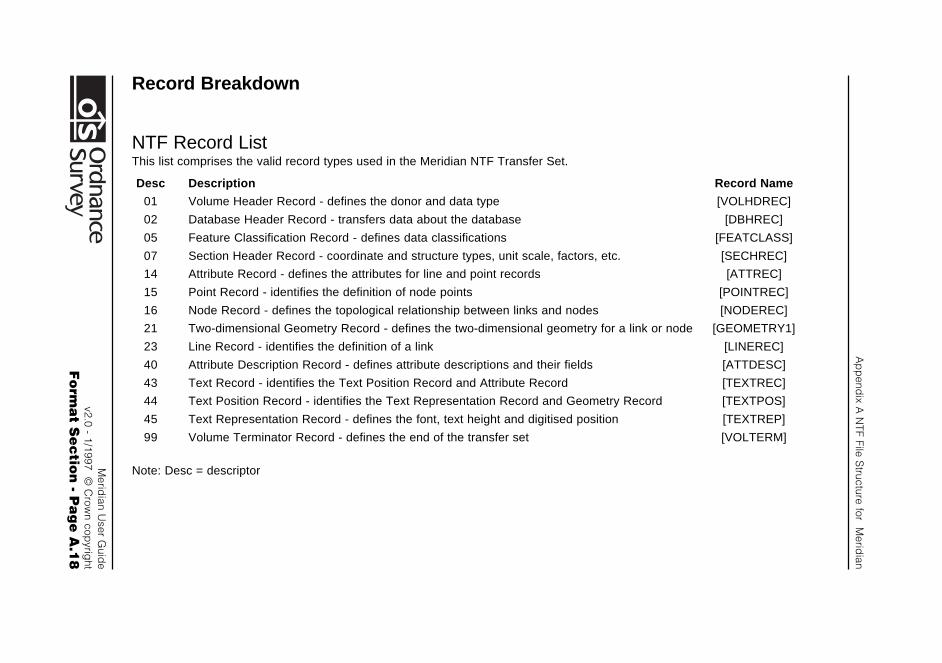
Ap
pend
ix A N
TF File Structure for M
eridian
Merid
ian User G
uide
v2.0 - 1/1997 © C
rown cop
yright
Fo
rma
t Se
ctio
n - P
ag
e A
.18
Record Breakdown
NTF Record ListThis list comprises the valid record types used in the Meridian NTF Transfer Set.
Desc Description Record Name
01 Volume Header Record - defines the donor and data type [VOLHDREC]
02 Database Header Record - transfers data about the database [DBHREC]
05 Feature Classification Record - defines data classifications [FEATCLASS]
07 Section Header Record - coordinate and structure types, unit scale, factors, etc. [SECHREC]
14 Attribute Record - defines the attributes for line and point records [ATTREC]
15 Point Record - identifies the definition of node points [POINTREC]
16 Node Record - defines the topological relationship between links and nodes [NODEREC]
21 Two-dimensional Geometry Record - defines the two-dimensional geometry for a link or node [GEOMETRY1]
23 Line Record - identifies the definition of a link [LINEREC]
40 Attribute Description Record - defines attribute descriptions and their fields [ATTDESC]
43 Text Record - identifies the Text Position Record and Attribute Record [TEXTREC]
44 Text Position Record - identifies the Text Representation Record and Geometry Record [TEXTPOS]
45 Text Representation Record - defines the font, text height and digitised position [TEXTREP]
99 Volume Terminator Record - defines the end of the transfer set [VOLTERM]
Note: Desc = descriptor
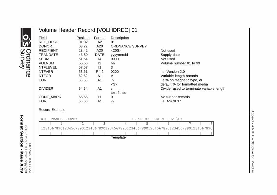
Ap
pend
ix A N
TF File Structure for M
eridian
Merid
ian User G
uide
v2.0 - 1/1997 © C
rown cop
yright
Fo
rma
t Se
ctio
n - P
ag
e A
.19
Volume Header Record [VOLHDREC] 01Field Position Format DescriptionREC_DESC 01:02 A2 01DONOR 03:22 A20 ORDNANCE SURVEYRECIPIENT 23:42 A20 <20S> Not usedTRANDATE 43:50 DATE yyyymmdd Supply dateSERIAL 51:54 I4 0000 Not usedVOLNUM 55:56 I2 nn Volume number 01 to 99NTFLEVEL 57:57 I1 3NTFVER 58:61 R4.2 0200 i.e. Version 2.0NTFOR 62:62 A1 V Variable length recordsEOR 63:63 A1 % i.e % on magnetic type, or
<S> default % for formatted mediaDIVIDER 64:64 A1 \ Divider used to terminate variable length
text fieldsCONT_MARK 65:65 I1 0 No further recordsEOR 66:66 A1 % i.e. ASCII 37
Record Example
01ORDNANCE SURVEY 1995113000000130200V \0% | 1 | 2 | 3 | 4 | 5 | 6 | 7 | 812345678901234567890123456789012345678901234567890123456789012345678901234567890 | | | | | | | | | | | | | | | |
Template

Ap
pend
ix A N
TF File Structure for M
eridian
Merid
ian User G
uide
v2.0 - 1/1997 © C
rown cop
yright
Fo
rma
t Se
ctio
n - P
ag
e A
.20
Database Header Record [DBHREC] 02Record 1Field Position Format DescriptionREC_DESC 01:02 A2 02DBNAME 03:22 A20 Meridian_01.95<6S> Database nameDDNAME 23:42 A20 DEFAULT_02.00<7S>DDATE 43:50 DATE 19920515 Release date of NTF version being usedDDBASE 51:70 A20 <20S> Not usedDDBDATE 71:78 DATE 00000000 Not usedCONT_MARK 79:79 I1 1 Followed by continuation recordEOR 80:80 A1 % i.e. ASCII 37
Record 2Field Position Format DescriptionREC_DESC 01:02 A2 00FCNAME 03:22 A20 Meridian_01.00<6S> Data Specification (Product Version)FCDATE 23:30 DATE 19950901 Date of Data SpecificationDQNAME 31:50 A20 <20S> Not usedDQDATE 51:58 DATE 00000000 Not usedDATA_MODEL 59:60 I2 00CONT_MARK 61:61 I1 0 No further recordsEOR 62:62 A1 % i.e. ASCII 37
Record Example
02Meridian_01.95 DEFAULT_02.00 19920515 000000001%00Meridian_01.00 19950901 00000000000% | 1 | 2 | 3 | 4 | 5 | 6 | 7 | 812345678901234567890123456789012345678901234567890123456789012345678901234567890 | | | | | | | | | | | | | | | |
Template
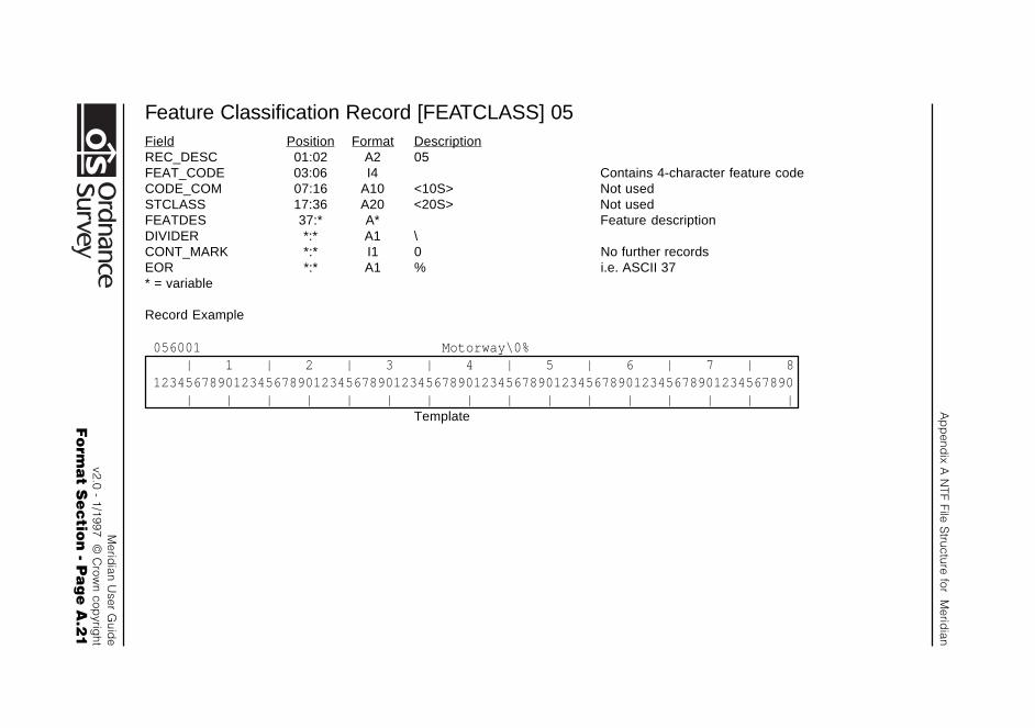
Ap
pend
ix A N
TF File Structure for M
eridian
Merid
ian User G
uide
v2.0 - 1/1997 © C
rown cop
yright
Fo
rma
t Se
ctio
n - P
ag
e A
.21
Feature Classification Record [FEATCLASS] 05Field Position Format DescriptionREC_DESC 01:02 A2 05FEAT_CODE 03:06 I4 Contains 4-character feature codeCODE_COM 07:16 A10 <10S> Not usedSTCLASS 17:36 A20 <20S> Not usedFEATDES 37:* A* Feature descriptionDIVIDER *:* A1 \CONT_MARK *:* I1 0 No further recordsEOR *:* A1 % i.e. ASCII 37* = variable
Record Example
056001 Motorway\0% | 1 | 2 | 3 | 4 | 5 | 6 | 7 | 812345678901234567890123456789012345678901234567890123456789012345678901234567890 | | | | | | | | | | | | | | | |
Template
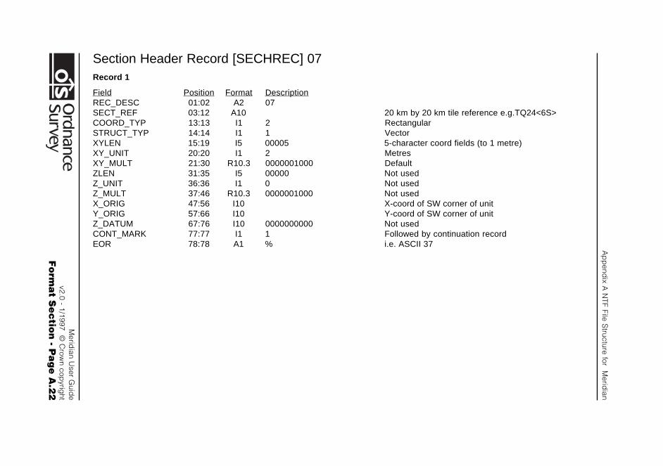
Ap
pend
ix A N
TF File Structure for M
eridian
Merid
ian User G
uide
v2.0 - 1/1997 © C
rown cop
yright
Fo
rma
t Se
ctio
n - P
ag
e A
.22
Section Header Record [SECHREC] 07Record 1
Field Position Format DescriptionREC_DESC 01:02 A2 07SECT_REF 03:12 A10 20 km by 20 km tile reference e.g.TQ24<6S>COORD_TYP 13:13 I1 2 RectangularSTRUCT_TYP 14:14 I1 1 VectorXYLEN 15:19 I5 00005 5-character coord fields (to 1 metre)XY_UNIT 20:20 I1 2 MetresXY_MULT 21:30 R10.3 0000001000 DefaultZLEN 31:35 I5 00000 Not usedZ_UNIT 36:36 I1 0 Not usedZ_MULT 37:46 R10.3 0000001000 Not usedX_ORIG 47:56 I10 X-coord of SW corner of unitY_ORIG 57:66 I10 Y-coord of SW corner of unitZ_DATUM 67:76 I10 0000000000 Not usedCONT_MARK 77:77 I1 1 Followed by continuation recordEOR 78:78 A1 % i.e. ASCII 37
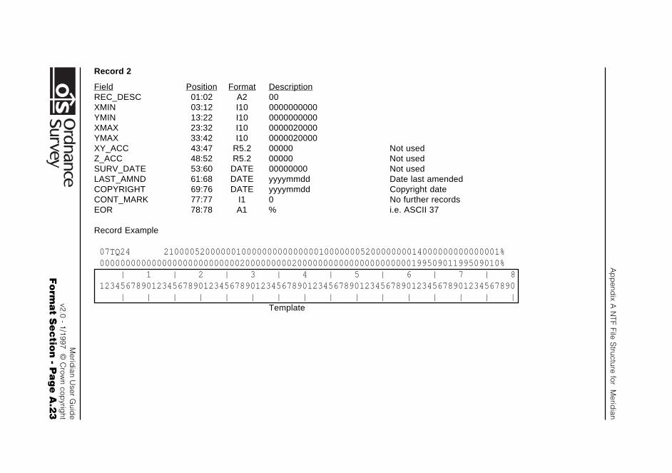
Ap
pend
ix A N
TF File Structure for M
eridian
Merid
ian User G
uide
v2.0 - 1/1997 © C
rown cop
yright
Fo
rma
t Se
ctio
n - P
ag
e A
.23
Record 2
Field Position Format DescriptionREC_DESC 01:02 A2 00XMIN 03:12 I10 0000000000YMIN 13:22 I10 0000000000XMAX 23:32 I10 0000020000YMAX 33:42 I10 0000020000XY_ACC 43:47 R5.2 00000 Not usedZ_ACC 48:52 R5.2 00000 Not usedSURV_DATE 53:60 DATE 00000000 Not usedLAST_AMND 61:68 DATE yyyymmdd Date last amendedCOPYRIGHT 69:76 DATE yyyymmdd Copyright dateCONT_MARK 77:77 I1 0 No further recordsEOR 78:78 A1 % i.e. ASCII 37
Record Example
07TQ24 21000052000000100000000000000010000000520000000014000000000000001%00000000000000000000000000020000000002000000000000000000000019950901199509010% | 1 | 2 | 3 | 4 | 5 | 6 | 7 | 812345678901234567890123456789012345678901234567890123456789012345678901234567890 | | | | | | | | | | | | | | | |
Template
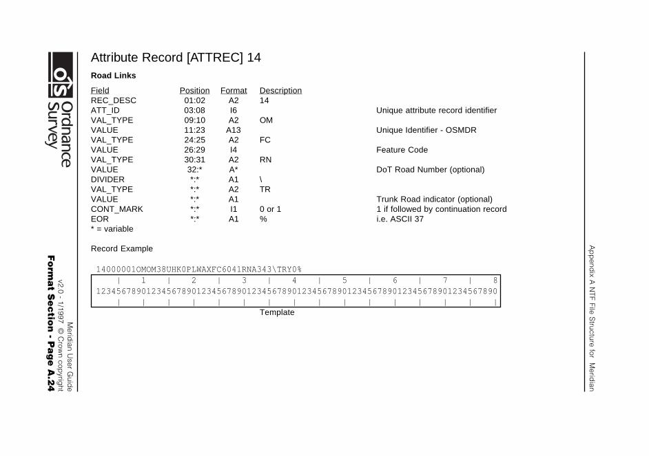
Ap
pend
ix A N
TF File Structure for M
eridian
Merid
ian User G
uide
v2.0 - 1/1997 © C
rown cop
yright
Fo
rma
t Se
ctio
n - P
ag
e A
.24
Attribute Record [ATTREC] 14Road Links
Field Position Format DescriptionREC_DESC 01:02 A2 14ATT_ID 03:08 I6 Unique attribute record identifierVAL_TYPE 09:10 A2 OMVALUE 11:23 A13 Unique Identifier - OSMDRVAL_TYPE 24:25 A2 FCVALUE 26:29 I4 Feature CodeVAL_TYPE 30:31 A2 RNVALUE 32:* A* DoT Road Number (optional)DIVIDER *:* A1 \VAL_TYPE *:* A2 TRVALUE *:* A1 Trunk Road indicator (optional)CONT_MARK *:* I1 0 or 1 1 if followed by continuation recordEOR *:* A1 % i.e. ASCII 37* = variable
Record Example
14000001OMOM38UHK0PLWAXFC6041RNA343\TRY0% | 1 | 2 | 3 | 4 | 5 | 6 | 7 | 812345678901234567890123456789012345678901234567890123456789012345678901234567890 | | | | | | | | | | | | | | | |
Template
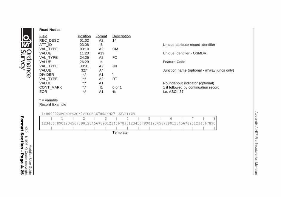
Ap
pend
ix A N
TF File Structure for M
eridian
Merid
ian User G
uide
v2.0 - 1/1997 © C
rown cop
yright
Fo
rma
t Se
ctio
n - P
ag
e A
.25
Road Nodes
Field Position Format DescriptionREC_DESC 01:02 A2 14ATT_ID 03:08 I6 Unique attribute record identifierVAL_TYPE 09:10 A2 OMVALUE 11:23 A13 Unique Identifier - OSMDRVAL_TYPE 24:25 A2 FCVALUE 26:29 I4 Feature CodeVAL_TYPE 30:31 A2 JNVALUE 32:* A* Junction name (optional - m’way juncs only)DIVIDER *:* A1 \VAL_TYPE *:* A2 RTVALUE *:* A1 Roundabout indicator (optional)CONT_MARK *:* I1 0 or 1 1 if followed by continuation recordEOR *:* A1 % i.e. ASCII 37
* = variableRecord Example
14000002OMOMDF42CK0VTEGFC6700JNM27 J2\RTY0% | 1 | 2 | 3 | 4 | 5 | 6 | 7 | 812345678901234567890123456789012345678901234567890123456789012345678901234567890 | | | | | | | | | | | | | | | |
Template
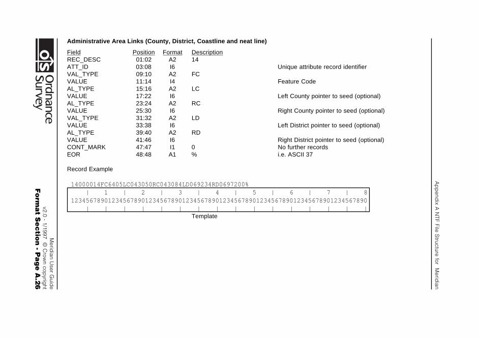
Ap
pend
ix A N
TF File Structure for M
eridian
Merid
ian User G
uide
v2.0 - 1/1997 © C
rown cop
yright
Fo
rma
t Se
ctio
n - P
ag
e A
.26
Administrative Area Links (County, District, Coastline and neat line)
Field Position Format DescriptionREC_DESC 01:02 A2 14ATT_ID 03:08 I6 Unique attribute record identifierVAL_TYPE 09:10 A2 FCVALUE 11:14 I4 Feature CodeAL_TYPE 15:16 A2 LCVALUE 17:22 I6 Left County pointer to seed (optional)AL_TYPE 23:24 A2 RCVALUE 25:30 I6 Right County pointer to seed (optional)VAL_TYPE 31:32 A2 LDVALUE 33:38 I6 Left District pointer to seed (optional)AL_TYPE 39:40 A2 RDVALUE 41:46 I6 Right District pointer to seed (optional)CONT_MARK 47:47 I1 0 No further recordsEOR 48:48 A1 % i.e. ASCII 37
Record Example
14000014FC6405LC043050RC043084LD069234RD0697200% | 1 | 2 | 3 | 4 | 5 | 6 | 7 | 812345678901234567890123456789012345678901234567890123456789012345678901234567890 | | | | | | | | | | | | | | | |
Template
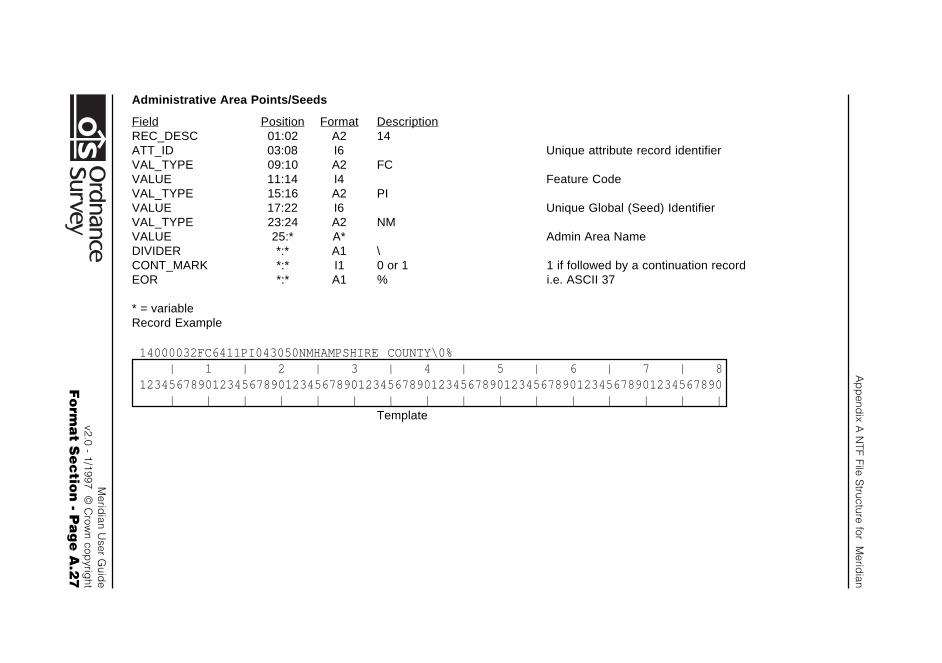
Ap
pend
ix A N
TF File Structure for M
eridian
Merid
ian User G
uide
v2.0 - 1/1997 © C
rown cop
yright
Fo
rma
t Se
ctio
n - P
ag
e A
.27
Administrative Area Points/Seeds
Field Position Format DescriptionREC_DESC 01:02 A2 14ATT_ID 03:08 I6 Unique attribute record identifierVAL_TYPE 09:10 A2 FCVALUE 11:14 I4 Feature CodeVAL_TYPE 15:16 A2 PIVALUE 17:22 I6 Unique Global (Seed) IdentifierVAL_TYPE 23:24 A2 NMVALUE 25:* A* Admin Area NameDIVIDER *:* A1 \CONT_MARK *:* I1 0 or 1 1 if followed by a continuation recordEOR *:* A1 % i.e. ASCII 37
* = variableRecord Example
14000032FC6411PI043050NMHAMPSHIRE COUNTY\0% | 1 | 2 | 3 | 4 | 5 | 6 | 7 | 812345678901234567890123456789012345678901234567890123456789012345678901234567890 | | | | | | | | | | | | | | | |
Template
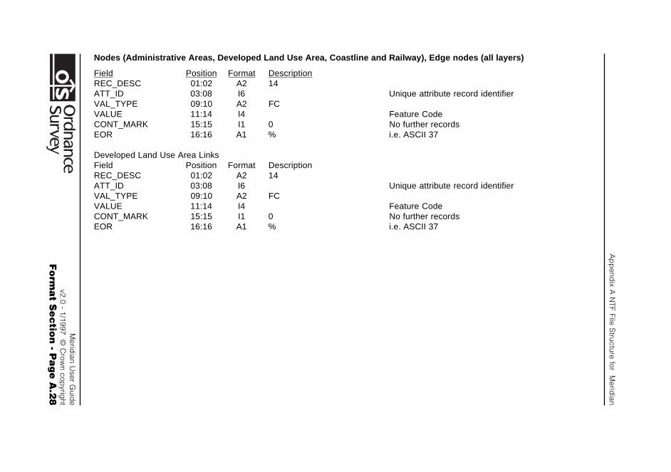
Ap
pend
ix A N
TF File Structure for M
eridian
Merid
ian User G
uide
v2.0 - 1/1997 © C
rown cop
yright
Fo
rma
t Se
ctio
n - P
ag
e A
.28
Nodes (Administrative Areas, Developed Land Use Area, Coastline and Railway), Edge nodes (all layers)
Field Position Format DescriptionREC_DESC 01:02 A2 14ATT_ID 03:08 I6 Unique attribute record identifierVAL_TYPE 09:10 A2 FCVALUE 11:14 I4 Feature CodeCONT_MARK 15:15 I1 0 No further recordsEOR 16:16 A1 % i.e. ASCII 37
Developed Land Use Area LinksField Position Format DescriptionREC_DESC 01:02 A2 14ATT_ID 03:08 I6 Unique attribute record identifierVAL_TYPE 09:10 A2 FCVALUE 11:14 I4 Feature CodeCONT_MARK 15:15 I1 0 No further recordsEOR 16:16 A1 % i.e. ASCII 37
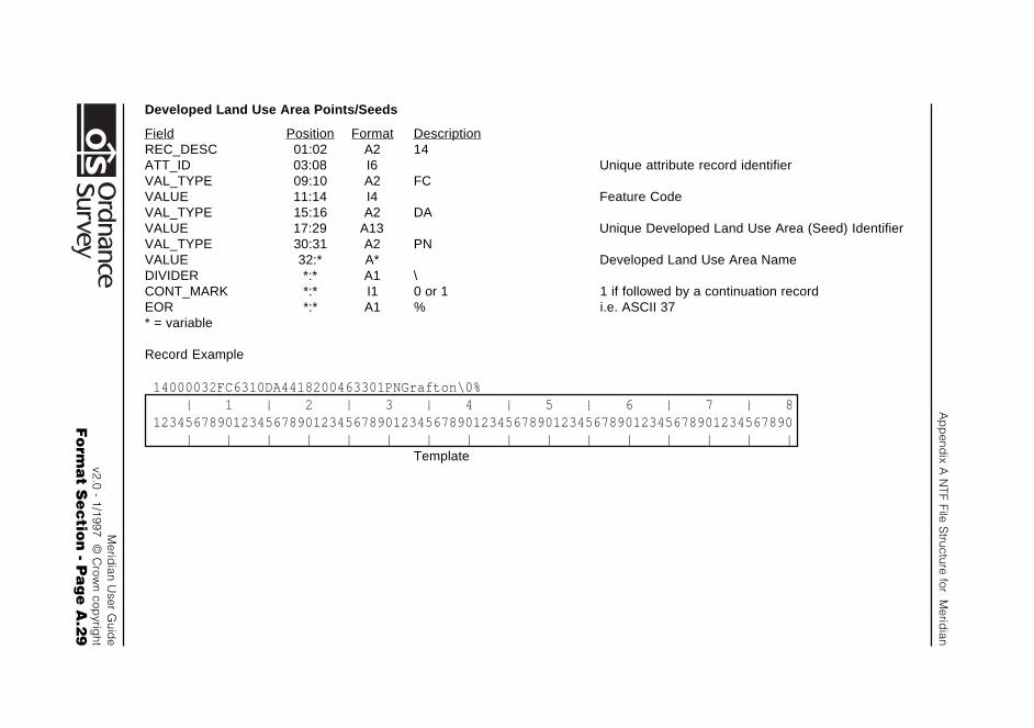
Ap
pend
ix A N
TF File Structure for M
eridian
Merid
ian User G
uide
v2.0 - 1/1997 © C
rown cop
yright
Fo
rma
t Se
ctio
n - P
ag
e A
.29
Developed Land Use Area Points/Seeds
Field Position Format DescriptionREC_DESC 01:02 A2 14ATT_ID 03:08 I6 Unique attribute record identifierVAL_TYPE 09:10 A2 FCVALUE 11:14 I4 Feature CodeVAL_TYPE 15:16 A2 DAVALUE 17:29 A13 Unique Developed Land Use Area (Seed) IdentifierVAL_TYPE 30:31 A2 PNVALUE 32:* A* Developed Land Use Area NameDIVIDER *:* A1 \CONT_MARK *:* I1 0 or 1 1 if followed by a continuation recordEOR *:* A1 % i.e. ASCII 37* = variable
Record Example
14000032FC6310DA4418200463301PNGrafton\0% | 1 | 2 | 3 | 4 | 5 | 6 | 7 | 812345678901234567890123456789012345678901234567890123456789012345678901234567890 | | | | | | | | | | | | | | | |
Template
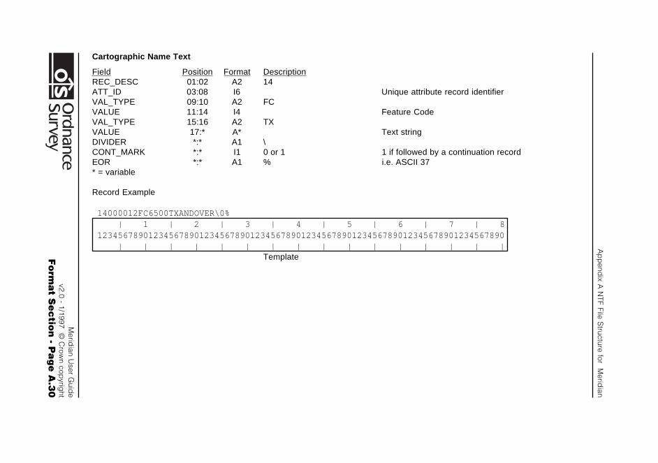
Ap
pend
ix A N
TF File Structure for M
eridian
Merid
ian User G
uide
v2.0 - 1/1997 © C
rown cop
yright
Fo
rma
t Se
ctio
n - P
ag
e A
.30
Cartographic Name Text
Field Position Format DescriptionREC_DESC 01:02 A2 14ATT_ID 03:08 I6 Unique attribute record identifierVAL_TYPE 09:10 A2 FCVALUE 11:14 I4 Feature CodeVAL_TYPE 15:16 A2 TXVALUE 17:* A* Text stringDIVIDER *:* A1 \CONT_MARK *:* I1 0 or 1 1 if followed by a continuation recordEOR *:* A1 % i.e. ASCII 37* = variable
Record Example
14000012FC6500TXANDOVER\0% | 1 | 2 | 3 | 4 | 5 | 6 | 7 | 812345678901234567890123456789012345678901234567890123456789012345678901234567890 | | | | | | | | | | | | | | | |
Template
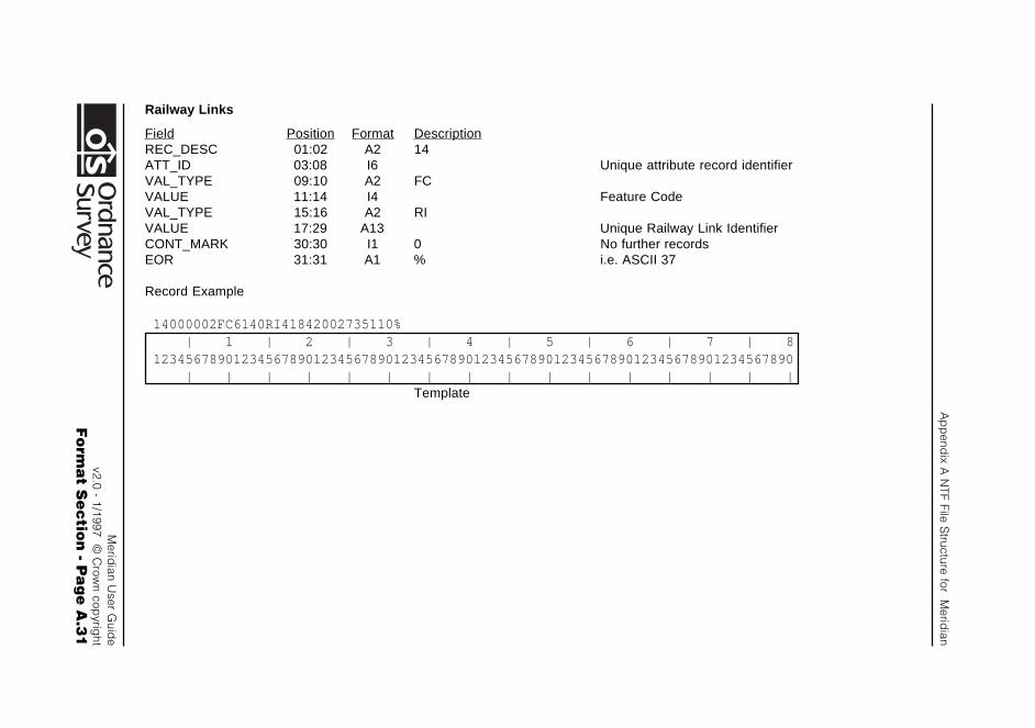
Ap
pend
ix A N
TF File Structure for M
eridian
Merid
ian User G
uide
v2.0 - 1/1997 © C
rown cop
yright
Fo
rma
t Se
ctio
n - P
ag
e A
.31
Railway Links
Field Position Format DescriptionREC_DESC 01:02 A2 14ATT_ID 03:08 I6 Unique attribute record identifierVAL_TYPE 09:10 A2 FCVALUE 11:14 I4 Feature CodeVAL_TYPE 15:16 A2 RIVALUE 17:29 A13 Unique Railway Link IdentifierCONT_MARK 30:30 I1 0 No further recordsEOR 31:31 A1 % i.e. ASCII 37
Record Example
14000002FC6140RI41842002735110% | 1 | 2 | 3 | 4 | 5 | 6 | 7 | 812345678901234567890123456789012345678901234567890123456789012345678901234567890 | | | | | | | | | | | | | | | |
Template
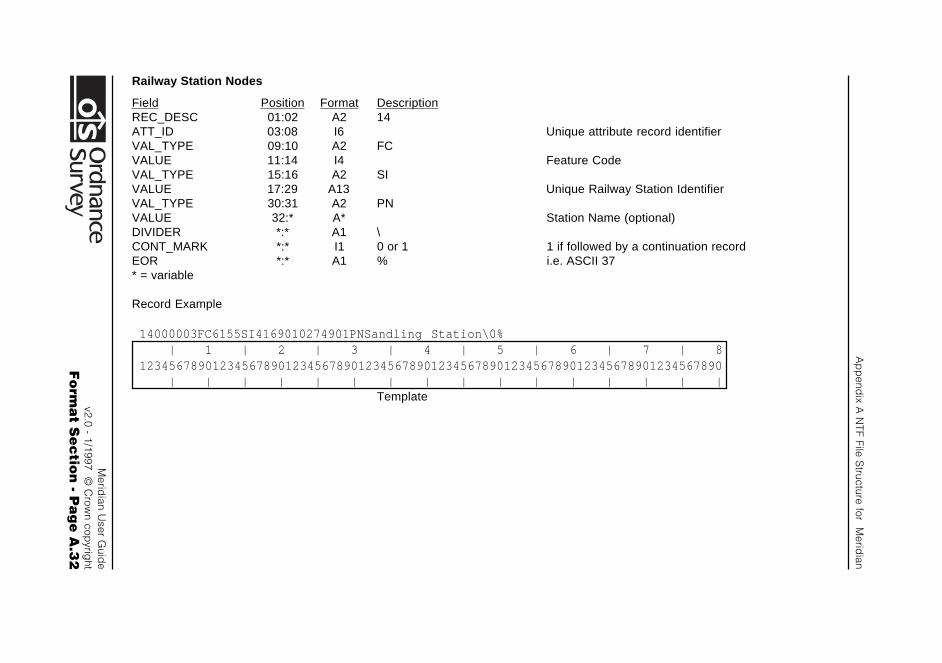
Ap
pend
ix A N
TF File Structure for M
eridian
Merid
ian User G
uide
v2.0 - 1/1997 © C
rown cop
yright
Fo
rma
t Se
ctio
n - P
ag
e A
.32
Railway Station Nodes
Field Position Format DescriptionREC_DESC 01:02 A2 14ATT_ID 03:08 I6 Unique attribute record identifierVAL_TYPE 09:10 A2 FCVALUE 11:14 I4 Feature CodeVAL_TYPE 15:16 A2 SIVALUE 17:29 A13 Unique Railway Station IdentifierVAL_TYPE 30:31 A2 PNVALUE 32:* A* Station Name (optional)DIVIDER *:* A1 \CONT_MARK *:* I1 0 or 1 1 if followed by a continuation recordEOR *:* A1 % i.e. ASCII 37* = variable
Record Example
14000003FC6155SI4169010274901PNSandling Station\0% | 1 | 2 | 3 | 4 | 5 | 6 | 7 | 812345678901234567890123456789012345678901234567890123456789012345678901234567890 | | | | | | | | | | | | | | | |
Template
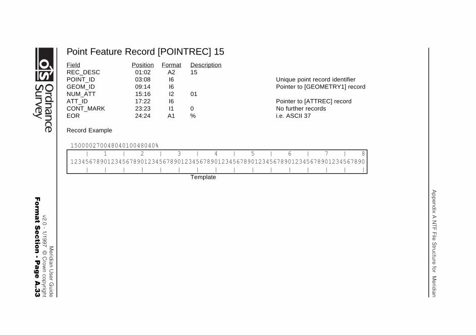
Ap
pend
ix A N
TF File Structure for M
eridian
Merid
ian User G
uide
v2.0 - 1/1997 © C
rown cop
yright
Fo
rma
t Se
ctio
n - P
ag
e A
.33
Point Feature Record [POINTREC] 15Field Position Format DescriptionREC_DESC 01:02 A2 15POINT_ID 03:08 I6 Unique point record identifierGEOM_ID 09:14 I6 Pointer to [GEOMETRY1] recordNUM_ATT 15:16 I2 01ATT_ID 17:22 I6 Pointer to [ATTREC] recordCONT_MARK 23:23 I1 0 No further recordsEOR 24:24 A1 % i.e. ASCII 37
Record Example
15000027004804010048040% | 1 | 2 | 3 | 4 | 5 | 6 | 7 | 812345678901234567890123456789012345678901234567890123456789012345678901234567890 | | | | | | | | | | | | | | | |
Template
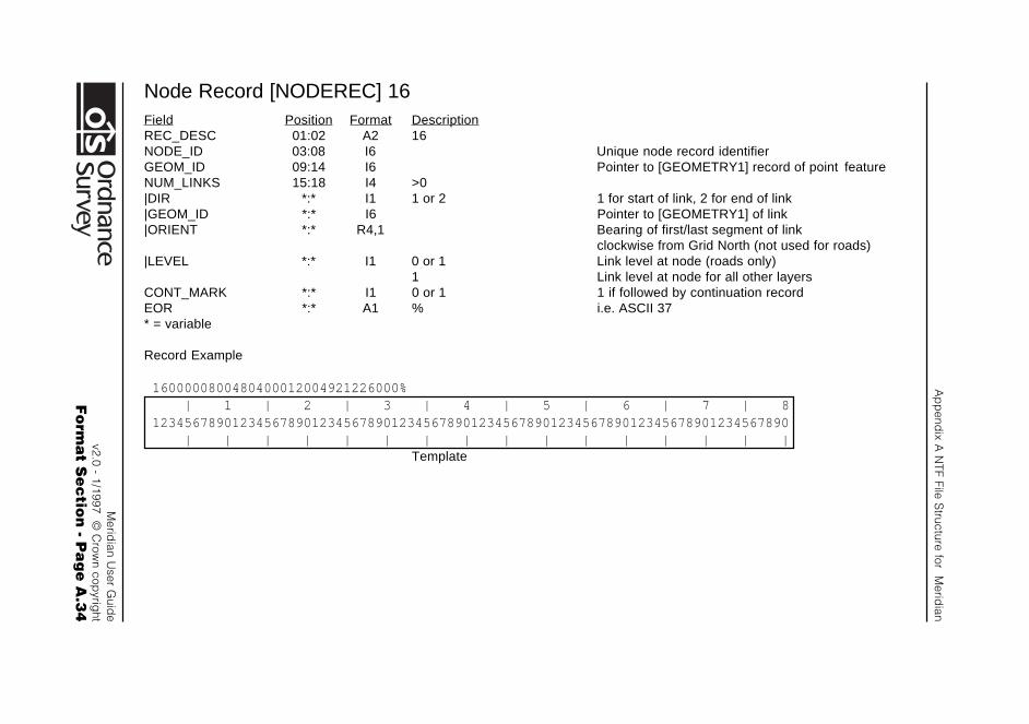
Ap
pend
ix A N
TF File Structure for M
eridian
Merid
ian User G
uide
v2.0 - 1/1997 © C
rown cop
yright
Fo
rma
t Se
ctio
n - P
ag
e A
.34
Node Record [NODEREC] 16Field Position Format DescriptionREC_DESC 01:02 A2 16NODE_ID 03:08 I6 Unique node record identifierGEOM_ID 09:14 I6 Pointer to [GEOMETRY1] record of point featureNUM_LINKS 15:18 I4 >0|DIR *:* I1 1 or 2 1 for start of link, 2 for end of link|GEOM_ID *:* I6 Pointer to [GEOMETRY1] of link|ORIENT *:* R4,1 Bearing of first/last segment of link
clockwise from Grid North (not used for roads)|LEVEL *:* I1 0 or 1 Link level at node (roads only)
1 Link level at node for all other layersCONT_MARK *:* I1 0 or 1 1 if followed by continuation recordEOR *:* A1 % i.e. ASCII 37* = variable
Record Example
1600000800480400012004921226000% | 1 | 2 | 3 | 4 | 5 | 6 | 7 | 812345678901234567890123456789012345678901234567890123456789012345678901234567890 | | | | | | | | | | | | | | | |
Template
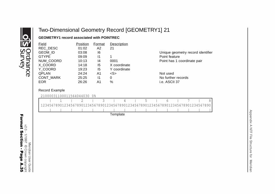
Ap
pend
ix A N
TF File Structure for M
eridian
Merid
ian User G
uide
v2.0 - 1/1997 © C
rown cop
yright
Fo
rma
t Se
ctio
n - P
ag
e A
.35
Two-Dimensional Geometry Record [GEOMETRY1] 21GEOMETRY1 record associated with POINTREC
Field Position Format DescriptionREC_DESC 01:02 A2 21GEOM_ID 03:08 I6 Unique geometry record identifierGTYPE 09:09 I1 1 Point featureNUM_COORD 10:13 I4 0001 Point has 1 coordinate pairX_COORD 14:18 I5 X coordinateY_COORD 19:23 I5 Y coordinateQPLAN 24:24 A1 <S> Not usedCONT_MARK 25:25 I1 0 No further recordsEOR 26:26 A1 % i.e. ASCII 37
Record Example
21000031100011564044030 0% | 1 | 2 | 3 | 4 | 5 | 6 | 7 | 812345678901234567890123456789012345678901234567890123456789012345678901234567890 | | | | | | | | | | | | | | | |
Template
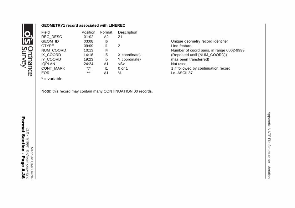
Ap
pend
ix A N
TF File Structure for M
eridian
Merid
ian User G
uide
v2.0 - 1/1997 © C
rown cop
yright
Fo
rma
t Se
ctio
n - P
ag
e A
.36
GEOMETRY1 record associated with LINEREC
Field Position Format DescriptionREC_DESC 01:02 A2 21GEOM_ID 03:08 I6 Unique geometry record identifierGTYPE 09:09 I1 2 Line featureNUM_COORD 10:13 I4 Number of coord pairs, in range 0002-9999|X_COORD 14:18 I5 X coordinate} (Repeated until {NUM_COORD})|Y_COORD 19:23 I5 Y coordinate} (has been transferred)|QPLAN 24:24 A1 <S> Not usedCONT_MARK *:* I1 0 or 1 1 if followed by continuation recordEOR *:* A1 % i.e. ASCII 37
* = variable
Note: this record may contain many CONTINUATION 00 records.

Ap
pend
ix A N
TF File Structure for M
eridian
Merid
ian User G
uide
v2.0 - 1/1997 © C
rown cop
yright
Fo
rma
t Se
ctio
n - P
ag
e A
.37
Line Feature Record [LINEREC] 23Field Position Format DescriptionREC_DESC 01:02 A2 23LINE_ID 03:08 I6 Unique line record identifierGEOM_ID 09:14 I6 Pointer to [GEOMETRY1] recordNUM_ATT 15:16 I2 01ATT_ID 17:22 I6 Pointer to [ATTREC] recordCONT_MARK 23:23 I1 0 No further recordsEOR 24:24 A1 % i.e. ASCII 37
Record Example
23004804005369010053690% | 1 | 2 | 3 | 4 | 5 | 6 | 7 | 812345678901234567890123456789012345678901234567890123456789012345678901234567890 | | | | | | | | | | | | | | | |
Template
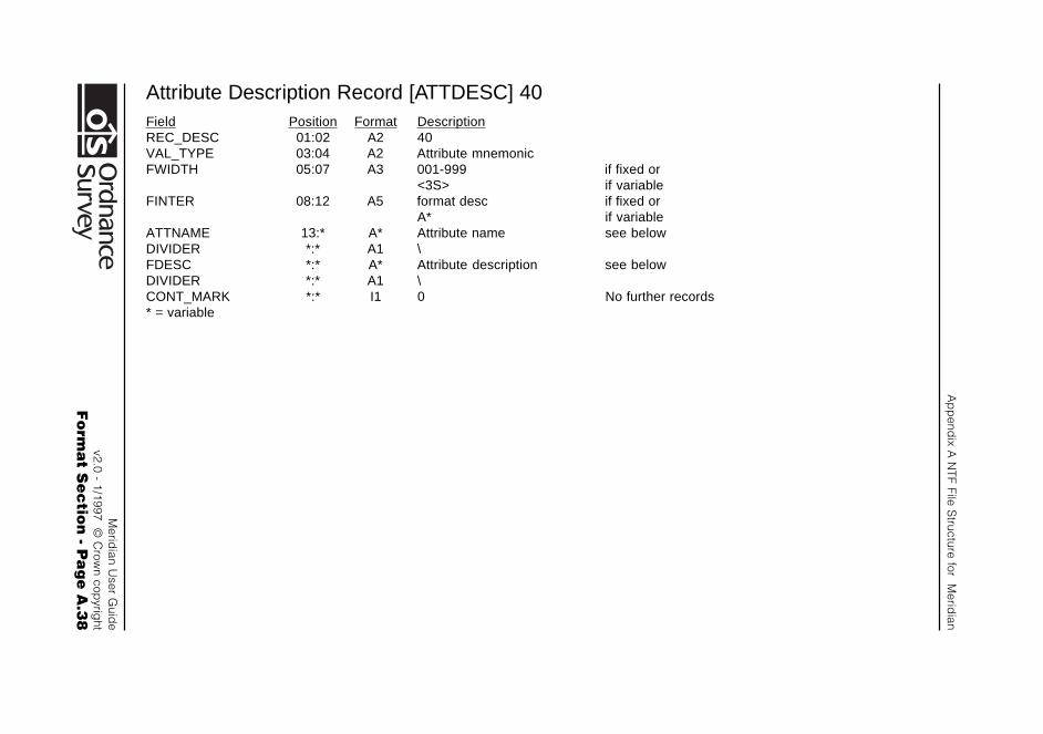
Ap
pend
ix A N
TF File Structure for M
eridian
Merid
ian User G
uide
v2.0 - 1/1997 © C
rown cop
yright
Fo
rma
t Se
ctio
n - P
ag
e A
.38
Attribute Description Record [ATTDESC] 40Field Position Format DescriptionREC_DESC 01:02 A2 40VAL_TYPE 03:04 A2 Attribute mnemonicFWIDTH 05:07 A3 001-999 if fixed or
<3S> if variableFINTER 08:12 A5 format desc if fixed or
A* if variableATTNAME 13:* A* Attribute name see belowDIVIDER *:* A1 \FDESC *:* A* Attribute description see belowDIVIDER *:* A1 \CONT_MARK *:* I1 0 No further records* = variable
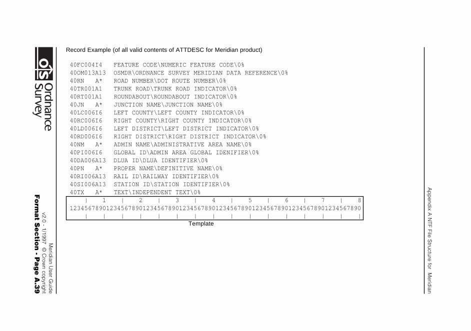
Ap
pend
ix A N
TF File Structure for M
eridian
Merid
ian User G
uide
v2.0 - 1/1997 © C
rown cop
yright
Fo
rma
t Se
ctio
n - P
ag
e A
.39
Record Example (of all valid contents of ATTDESC for Meridian product)
40FC004I4 FEATURE CODE\NUMERIC FEATURE CODE\0%40OM013A13 OSMDR\ORDNANCE SURVEY MERIDIAN DATA REFERENCE\0%40RN A* ROAD NUMBER\DOT ROUTE NUMBER\0%40TR001A1 TRUNK ROAD\TRUNK ROAD INDICATOR\0%40RT001A1 ROUNDABOUT\ROUNDABOUT INDICATOR\0%40JN A* JUNCTION NAME\JUNCTION NAME\0%40LC006I6 LEFT COUNTY\LEFT COUNTY INDICATOR\0%40RC006I6 RIGHT COUNTY\RIGHT COUNTY INDICATOR\0%40LD006I6 LEFT DISTRICT\LEFT DISTRICT INDICATOR\0%40RD006I6 RIGHT DISTRICT\RIGHT DISTRICT INDICATOR\0%40NM A* ADMIN NAME\ADMINISTRATIVE AREA NAME\0%40PI006I6 GLOBAL ID\ADMIN AREA GLOBAL IDENIFIER\0%40DA006A13 DLUA ID\DLUA IDENTIFIER\0%40PN A* PROPER NAME\DEFINITIVE NAME\0%40RI006A13 RAIL ID\RAILWAY IDENTIFIER\0%40SI006A13 STATION ID\STATION IDENTIFIER\0%40TX A* TEXT\INDEPENDENT TEXT\0% | 1 | 2 | 3 | 4 | 5 | 6 | 7 | 812345678901234567890123456789012345678901234567890123456789012345678901234567890 | | | | | | | | | | | | | | | |
Template
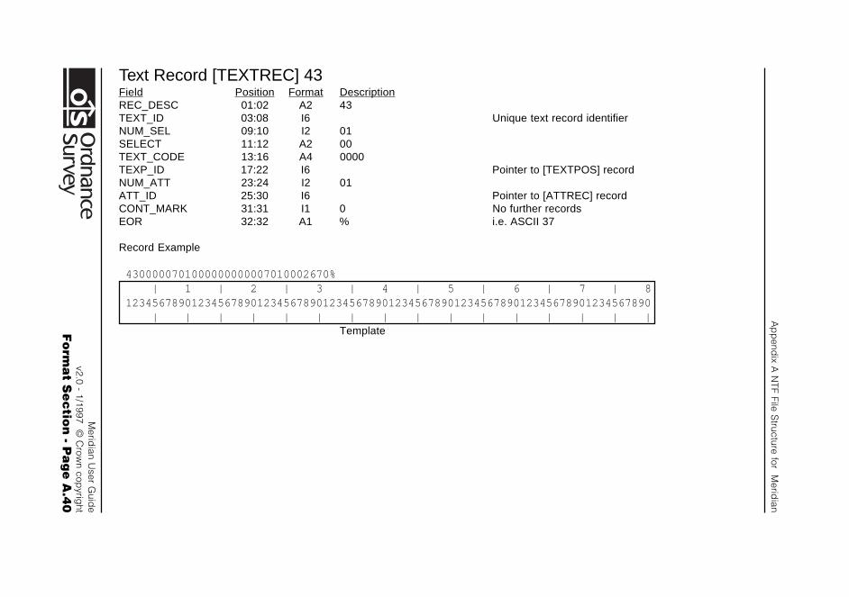
Ap
pend
ix A N
TF File Structure for M
eridian
Merid
ian User G
uide
v2.0 - 1/1997 © C
rown cop
yright
Fo
rma
t Se
ctio
n - P
ag
e A
.40
Text Record [TEXTREC] 43Field Position Format DescriptionREC_DESC 01:02 A2 43TEXT_ID 03:08 I6 Unique text record identifierNUM_SEL 09:10 I2 01SELECT 11:12 A2 00TEXT_CODE 13:16 A4 0000TEXP_ID 17:22 I6 Pointer to [TEXTPOS] recordNUM_ATT 23:24 I2 01ATT_ID 25:30 I6 Pointer to [ATTREC] recordCONT_MARK 31:31 I1 0 No further recordsEOR 32:32 A1 % i.e. ASCII 37
Record Example
4300000701000000000007010002670% | 1 | 2 | 3 | 4 | 5 | 6 | 7 | 812345678901234567890123456789012345678901234567890123456789012345678901234567890 | | | | | | | | | | | | | | | |
Template
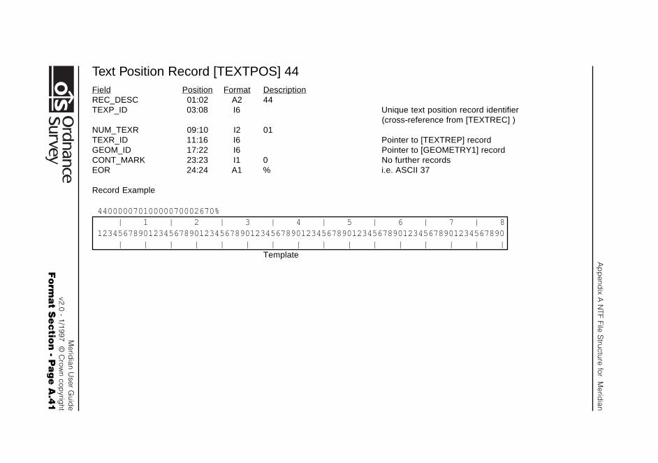
Ap
pend
ix A N
TF File Structure for M
eridian
Merid
ian User G
uide
v2.0 - 1/1997 © C
rown cop
yright
Fo
rma
t Se
ctio
n - P
ag
e A
.41
Text Position Record [TEXTPOS] 44Field Position Format DescriptionREC_DESC 01:02 A2 44TEXP_ID 03:08 I6 Unique text position record identifier
(cross-reference from [TEXTREC] )NUM_TEXR 09:10 I2 01TEXR_ID 11:16 I6 Pointer to [TEXTREP] recordGEOM_ID 17:22 I6 Pointer to [GEOMETRY1] recordCONT_MARK 23:23 I1 0 No further recordsEOR 24:24 A1 % i.e. ASCII 37
Record Example
44000007010000070002670% | 1 | 2 | 3 | 4 | 5 | 6 | 7 | 812345678901234567890123456789012345678901234567890123456789012345678901234567890 | | | | | | | | | | | | | | | |
Template
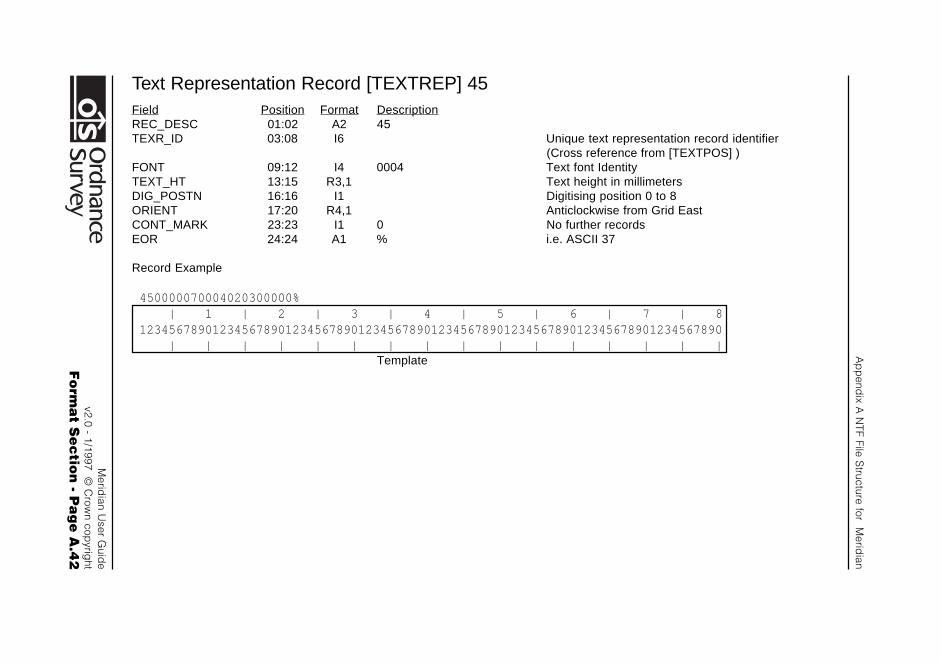
Ap
pend
ix A N
TF File Structure for M
eridian
Merid
ian User G
uide
v2.0 - 1/1997 © C
rown cop
yright
Fo
rma
t Se
ctio
n - P
ag
e A
.42
Text Representation Record [TEXTREP] 45Field Position Format DescriptionREC_DESC 01:02 A2 45TEXR_ID 03:08 I6 Unique text representation record identifier
(Cross reference from [TEXTPOS] )FONT 09:12 I4 0004 Text font IdentityTEXT_HT 13:15 R3,1 Text height in millimetersDIG_POSTN 16:16 I1 Digitising position 0 to 8ORIENT 17:20 R4,1 Anticlockwise from Grid EastCONT_MARK 23:23 I1 0 No further recordsEOR 24:24 A1 % i.e. ASCII 37
Record Example
450000070004020300000% | 1 | 2 | 3 | 4 | 5 | 6 | 7 | 812345678901234567890123456789012345678901234567890123456789012345678901234567890 | | | | | | | | | | | | | | | |
Template
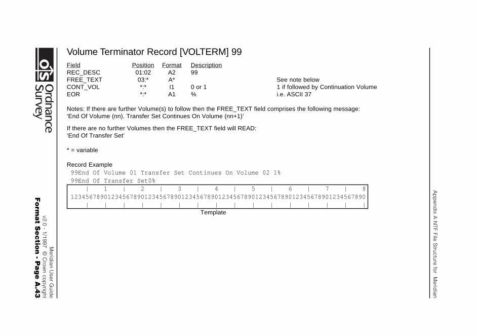
Ap
pend
ix A N
TF File Structure for M
eridian
Merid
ian User G
uide
v2.0 - 1/1997 © C
rown cop
yright
Fo
rma
t Se
ctio
n - P
ag
e A
.43
Volume Terminator Record [VOLTERM] 99Field Position Format DescriptionREC_DESC 01:02 A2 99FREE_TEXT 03:* A* See note belowCONT_VOL *:* I1 0 or 1 1 if followed by Continuation VolumeEOR *:* A1 % i.e. ASCII 37
Notes: If there are further Volume(s) to follow then the FREE_TEXT field comprises the following message:‘End Of Volume (nn). Transfer Set Continues On Volume (nn+1)’
If there are no further Volumes then the FREE_TEXT field will READ:‘End Of Transfer Set’
* = variable
Record Example99End Of Volume 01 Transfer Set Continues On Volume 02 1%99End Of Transfer Set0% | 1 | 2 | 3 | 4 | 5 | 6 | 7 | 812345678901234567890123456789012345678901234567890123456789012345678901234567890 | | | | | | | | | | | | | | | |
Template

Appendix A NTF File Structure for Meridian
Meridian User Guidev2.0 - 1/1997 © Crown copyright
Format Section - Page A.44
Appendix B DXF File Structure for Meridian
Meridian User Guidev2.0 - 1/1997 © Crown copyright
Format Section - Page B.1
Appendix B DXF File Structure for Meridian
General
The following paragraphs describe the DXF group and sectionstructure for the transfer of Meridian.
It is assumed that the reader of this Appendix is familar withAppendix C of the AutoCAD reference manual, which ispublished by Autodesk Ltd, Cross Lane, GUILDFORDGU1 1UJ, or an equivalent document published by the reader’ssoftware supplier if a CAD package other than AutoCAD is to beused.
Meridian DXF files containing Ordnance Survey data can bevery large and so are supplied on CD-ROM media only
The following section gives a detailed breakdown of the datastructure of Meridian in DXF.
This is a two stage procedure which consists of:
1. Diagrammatic view of the Data Structure with a precedingoutline description of that part of the data structure
2. Detailed examples of the record sequence and contents ofthe data structure. A diagram of the Record Group precedeseach example.
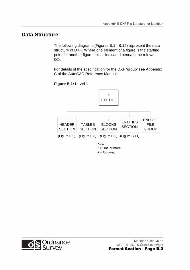
Appendix B DXF File Structure for Meridian
Meridian User Guidev2.0 - 1/1997 © Crown copyright
Format Section - Page B.2
Data Structure
The following diagrams (Figures B.1 - B.14) represent the datastructure of DXF. Where one element of a figure is the startingpoint for another figure, this is indicated beneath the relevantbox.
For details of the specification for the DXF ‘group’ see AppendixC of the AutoCAD Reference Manual.
Figure B.1: Level 1
+ HEADER SECTION
+ TABLES
SECTION
+ BLOCKS SECTION
ENTITIES SECTION
END OF FILE
GROUP
* DXF FILE
(Figure B.2) (Figure B.3) (Figure B.9) (Figure B.11)
Key: * = One or more + = Optional
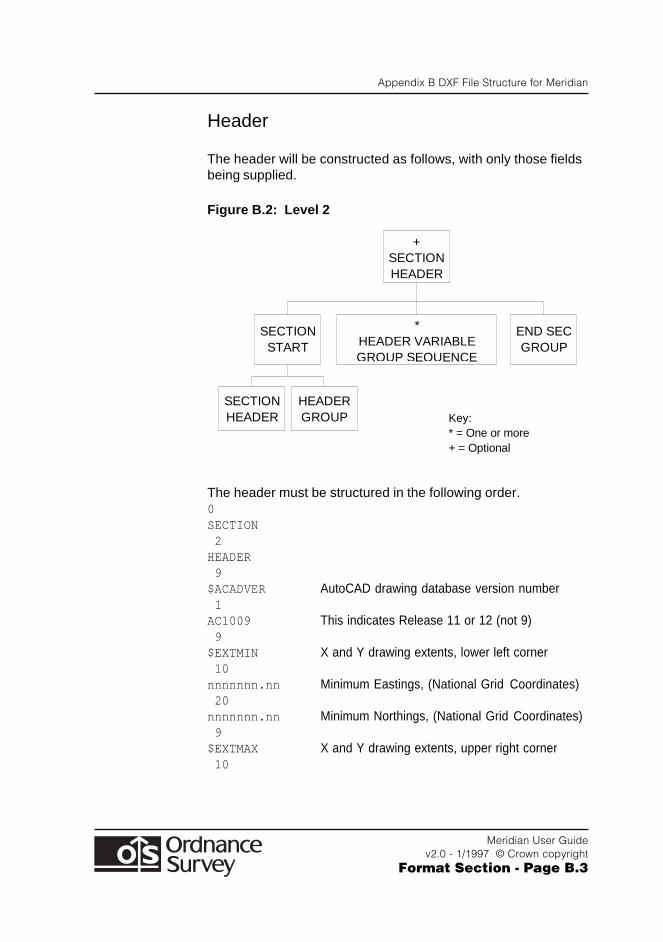
Appendix B DXF File Structure for Meridian
Meridian User Guidev2.0 - 1/1997 © Crown copyright
Format Section - Page B.3
Header
The header will be constructed as follows, with only those fieldsbeing supplied.
Figure B.2: Level 2
+ SECTION HEADER
SECTION START
SECTION HEADER
HEADER GROUP
END SEC GROUP
* HEADER VARIABLE GROUP SEQUENCE
Key: * = One or more + = Optional
The header must be structured in the following order.0SECTION 2HEADER 9$ACADVER AutoCAD drawing database version number 1AC1009 This indicates Release 11 or 12 (not 9) 9$EXTMIN X and Y drawing extents, lower left corner 10nnnnnnn.nn Minimum Eastings, (National Grid Coordinates) 20nnnnnnn.nn Minimum Northings, (National Grid Coordinates) 9$EXTMAX X and Y drawing extents, upper right corner 10
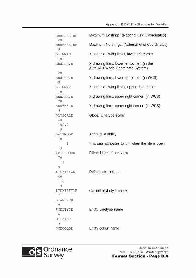
Appendix B DXF File Structure for Meridian
Meridian User Guidev2.0 - 1/1997 © Crown copyright
Format Section - Page B.4
nnnnnnn.nn Maximum Eastings, (National Grid Coordinates) 20nnnnnnn.nn Maximum Northings, (National Grid Coordinates) 9$LIMMIN X and Y drawing limits, lower left corner 10nnnnnn.n X drawing limit, lower left corner, (in the
AutoCAD World Coordinate System) 20nnnnnn.n Y drawing limit, lower left corner, (in WCS) 9$LIMMAX X and Y drawing limits, upper right corner 10nnnnnn.n X drawing limit, upper right corner, (in WCS) 20nnnnnn.n Y drawing limit, upper right corner, (in WCS) 9$LTSCALE Global Linetype scale 40 100.0 9$ATTMODE Attribute visibility 70 1 This sets attributes to ‘on’ when the file is open 9$FILLMODE Fillmode ‘on’ if non-zero 70 1 9$TEXTSIZE Default text height 40 1.0 9$TEXTSTYLE Current text style name 7STANDARD 9$CELTYPE Entity Linetype name 6BYLAYER 9$CECOLOR Entity colour name
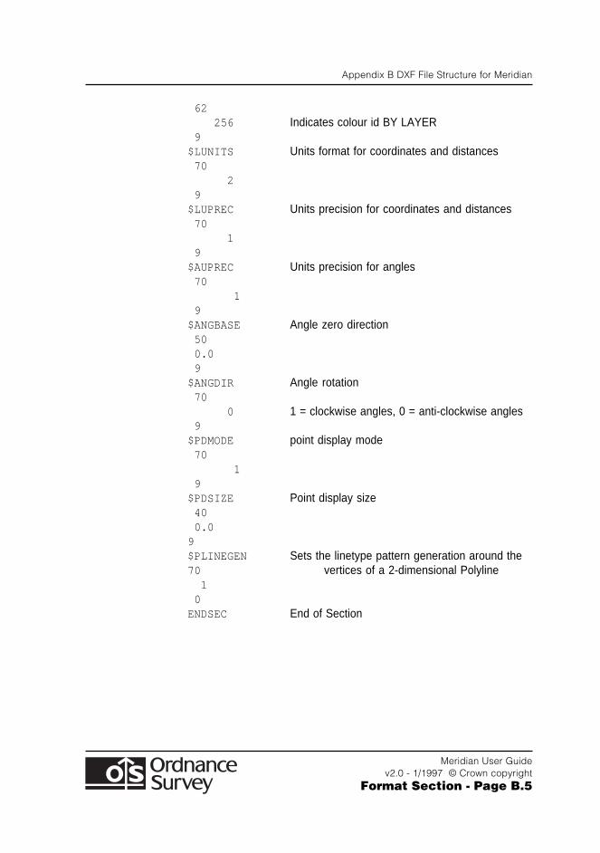
Appendix B DXF File Structure for Meridian
Meridian User Guidev2.0 - 1/1997 © Crown copyright
Format Section - Page B.5
62 256 Indicates colour id BY LAYER 9$LUNITS Units format for coordinates and distances 70 2 9$LUPREC Units precision for coordinates and distances 70 1 9$AUPREC Units precision for angles 70 1 9$ANGBASE Angle zero direction 50 0.0 9$ANGDIR Angle rotation 70 0 1 = clockwise angles, 0 = anti-clockwise angles 9$PDMODE point display mode 70 1 9$PDSIZE Point display size 40 0.09$PLINEGEN Sets the linetype pattern generation around the70 vertices of a 2-dimensional Polyline 1 0ENDSEC End of Section

Appendix B DXF File Structure for Meridian
Meridian User Guidev2.0 - 1/1997 © Crown copyright
Format Section - Page B.6
Tables
Figure B.3: Level 2
+ TABLES
SECTION
SECTION START
+ LINETYPE
TABLE
+ LAYER TABLE
+ STYLE TABLE
ENDSEC GROUP
TABLES GROUP
SECTION GROUP
Key: + = Optional
(Figure B.4)
The Tables Secion will follow the Header Section and willcontain three tables:
● Linetype Table
● Layer Table
● Style Table.
Figure B.4: Linetype Table Level 3
+ LINETYPE
TABLE
* LINETYPE
DEFINITIONS
TABLE START
ENDTAB GROUP
TABLE GROUP
LTYPE GROUP
FLAGS GROUP
Key: * = One or more + = Optional
(Figure B.5)
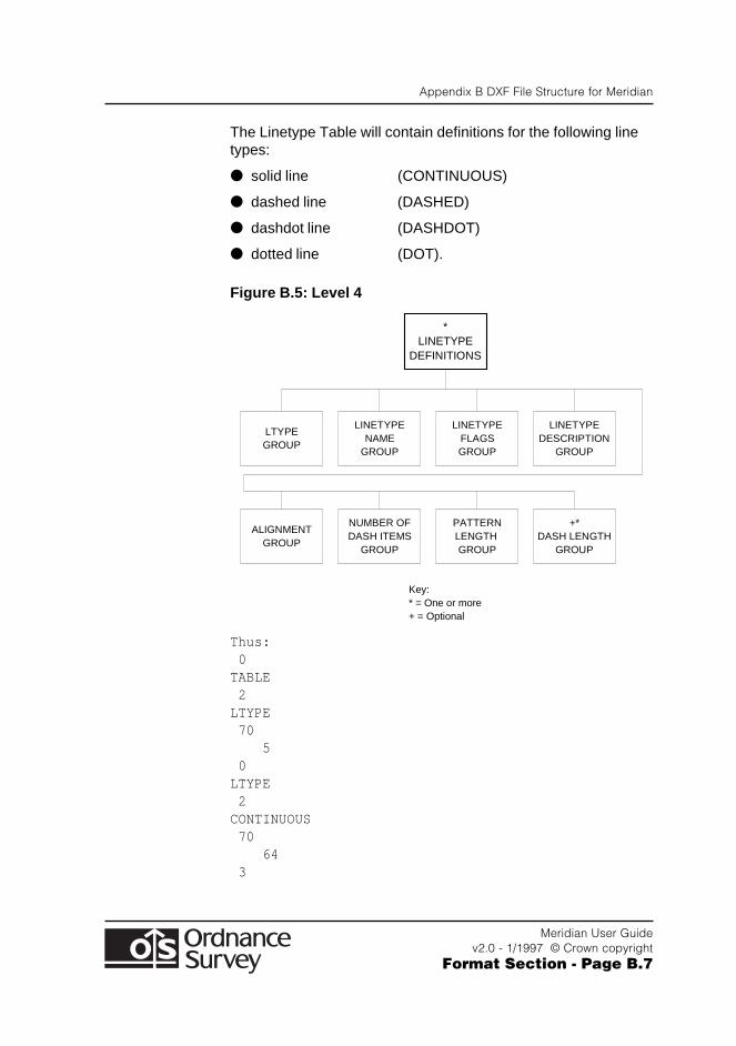
Appendix B DXF File Structure for Meridian
Meridian User Guidev2.0 - 1/1997 © Crown copyright
Format Section - Page B.7
The Linetype Table will contain definitions for the following linetypes:
● solid line (CONTINUOUS)
● dashed line (DASHED)
● dashdot line (DASHDOT)
● dotted line (DOT).
Figure B.5: Level 4
* LINETYPE
DEFINITIONS
LTYPE GROUP
LINETYPE NAME
GROUP
LINETYPE FLAGS GROUP
LINETYPE DESCRIPTION
GROUP
ALIGNMENT GROUP
NUMBER OF DASH ITEMS
GROUP
PATTERN LENGTH GROUP
+* DASH LENGTH
GROUP
Key: * = One or more + = Optional
Thus: 0TABLE 2LTYPE 70 5 0LTYPE 2CONTINUOUS 70 64 3
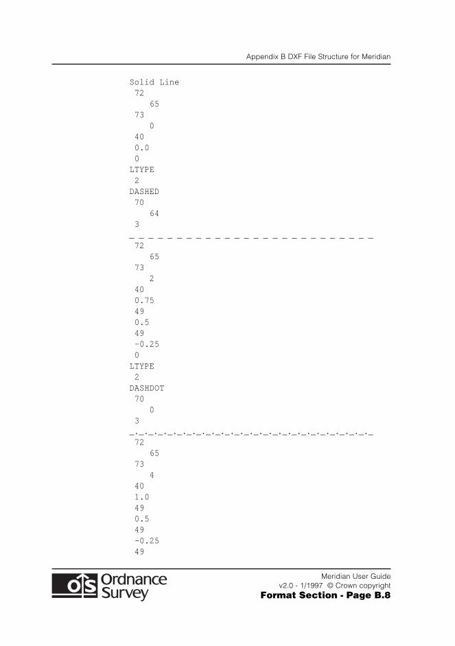
Appendix B DXF File Structure for Meridian
Meridian User Guidev2.0 - 1/1997 © Crown copyright
Format Section - Page B.8
Solid Line 72 65 73 0 40 0.0 0LTYPE 2DASHED 70 64 3_ _ _ _ _ _ _ _ _ _ _ _ _ _ _ _ _ _ _ _ _ _ _ _ _ _ 72 65 73 2 40 0.75 49 0.5 49 -0.25 0LTYPE 2DASHDOT 70 0 3_._._._._._._._._._._._._._._._._._._._._._._._._._ 72 65 73 4 40 1.0 49 0.5 49 -0.25 49
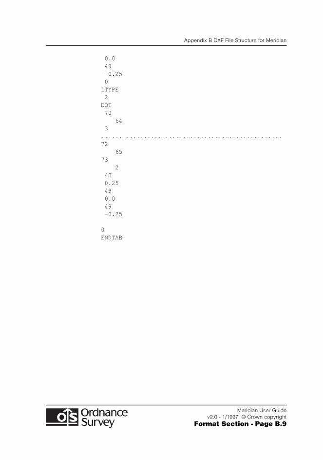
Appendix B DXF File Structure for Meridian
Meridian User Guidev2.0 - 1/1997 © Crown copyright
Format Section - Page B.9
0.0 49 -0.25 0LTYPE 2DOT 70 64 3...................................................72 6573 2 40 0.25 49 0.0 49 -0.25
0ENDTAB
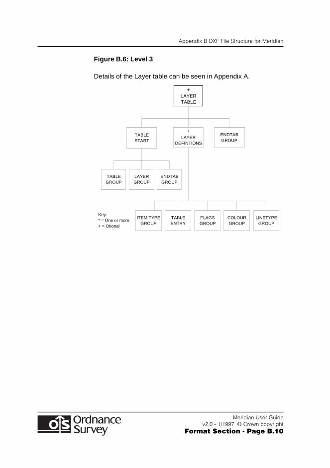
Appendix B DXF File Structure for Meridian
Meridian User Guidev2.0 - 1/1997 © Crown copyright
Format Section - Page B.10
Figure B.6: Level 3
Details of the Layer table can be seen in Appendix A.
+ LAYER TABLE
TABLE START
* LAYER
DEFINTIONS
ENDTAB GROUP
TABLE GROUP
LAYER GROUP
ENDTAB GROUP
ITEM TYPE GROUP
TABLE ENTRY
FLAGS GROUP
COLOUR GROUP
LINETYPE GROUP
Key: * = One or more + = Otional
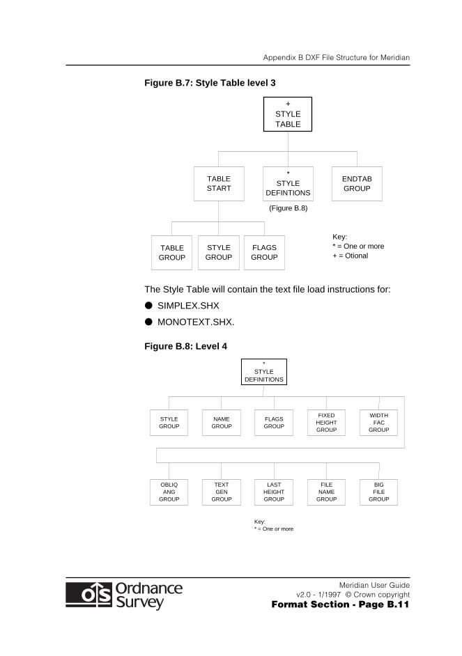
Appendix B DXF File Structure for Meridian
Meridian User Guidev2.0 - 1/1997 © Crown copyright
Format Section - Page B.11
Figure B.7: Style Table level 3
+ STYLE TABLE
TABLE START
* STYLE
DEFINTIONS
ENDTAB GROUP
TABLE GROUP
STYLE GROUP
FLAGS GROUP
Key: * = One or more + = Otional
(Figure B.8)
The Style Table will contain the text file load instructions for:
● SIMPLEX.SHX
● MONOTEXT.SHX.
Figure B.8: Level 4
* STYLE
DEFINITIONS
STYLE GROUP
NAME GROUP
FLAGS GROUP
Key: * = One or more
FIXED HEIGHT GROUP
WIDTH FAC
GROUP
OBLIQ ANG
GROUP
TEXT GEN
GROUP
LAST HEIGHT GROUP
FILE NAME
GROUP
BIG FILE
GROUP
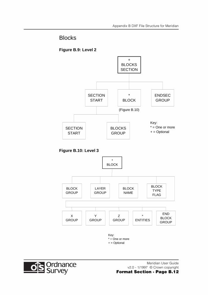
Appendix B DXF File Structure for Meridian
Meridian User Guidev2.0 - 1/1997 © Crown copyright
Format Section - Page B.12
Blocks
Figure B.9: Level 2
+ BLOCKS SECTION
* BLOCK
SECTION START
ENDSEC GROUP
SECTION START
BLOCKS GROUP
Key: * = One or more + = Optional
(Figure B.10)
Figure B.10: Level 3
* BLOCK
LAYER GROUP
BLOCK GROUP
BLOCK NAME
Key: * = One or more + = Optional
BLOCK TYPE FLAG
Y GROUP
X GROUP
Z GROUP
* ENTITIES
END BLOCK GROUP
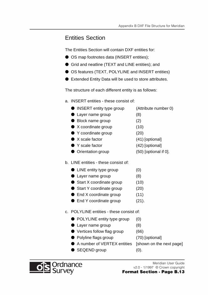
Appendix B DXF File Structure for Meridian
Meridian User Guidev2.0 - 1/1997 © Crown copyright
Format Section - Page B.13
Entities Section
The Entities Section will contain DXF entities for:
● OS map footnotes data (INSERT entities);
● Grid and neatline (TEXT and LINE entities); and
● OS features (TEXT, POLYLINE and INSERT entities)
● Extended Entity Data will be used to store attributes.
The structure of each different entity is as follows:
a. INSERT entities - these consist of:
● INSERT entity type group (Attribute number 0)
● Layer name group (8)
● Block name group (2)
● X coordinate group (10)
● Y coordinate group (20)
● X scale factor (41) [optional]
● Y scale factor (42) [optional]
● Orientation group (50) [optional if 0].
b. LINE entities - these consist of:
● LINE entity type group (0)
● Layer name group (8)
● Start X coordinate group (10)
● Start Y coordinate group (20)
● End X coordinate group (11)
● End Y coordinate group (21).
c. POLYLINE entities - these consist of:
● POLYLINE entity type group (0)
● Layer name group (8)
● Vertices follow flag group (66)
● Polyline flags group (70) [optional]
● A number of VERTEX entities [shown on the next page]
● SEQEND group (0).
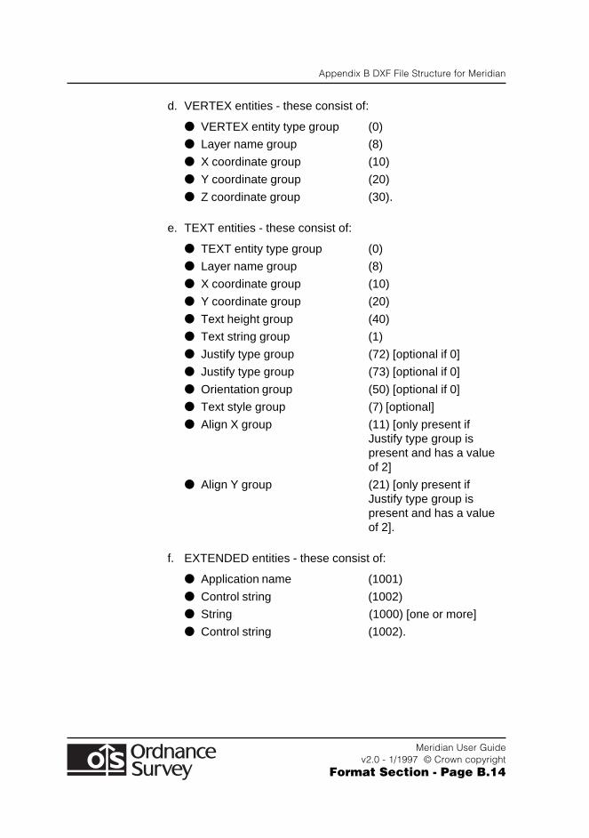
Appendix B DXF File Structure for Meridian
Meridian User Guidev2.0 - 1/1997 © Crown copyright
Format Section - Page B.14
d. VERTEX entities - these consist of:
● VERTEX entity type group (0)
● Layer name group (8)
● X coordinate group (10)
● Y coordinate group (20)
● Z coordinate group (30).
e. TEXT entities - these consist of:
● TEXT entity type group (0)
● Layer name group (8)
● X coordinate group (10)
● Y coordinate group (20)
● Text height group (40)
● Text string group (1)
● Justify type group (72) [optional if 0]
● Justify type group (73) [optional if 0]
● Orientation group (50) [optional if 0]
● Text style group (7) [optional]
● Align X group (11) [only present ifJustify type group ispresent and has a valueof 2]
● Align Y group (21) [only present ifJustify type group ispresent and has a valueof 2].
f. EXTENDED entities - these consist of:
● Application name (1001)
● Control string (1002)
● String (1000) [one or more]
● Control string (1002).
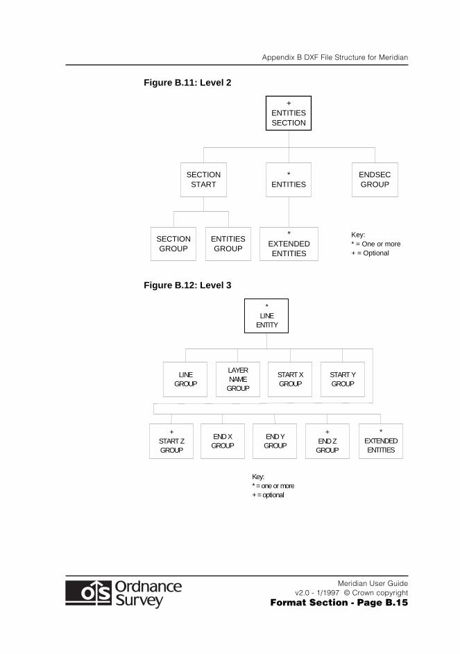
Appendix B DXF File Structure for Meridian
Meridian User Guidev2.0 - 1/1997 © Crown copyright
Format Section - Page B.15
Figure B.11: Level 2
+ ENTITIES SECTION
* ENTITIES
SECTION START
ENDSEC GROUP
SECTION GROUP
ENTITIES GROUP
Key: * = One or more + = Optional
* EXTENDED ENTITIES
Figure B.12: Level 3
* LINE
ENTITY
LINE GROUP
LAYER NAME
GROUP
START X GROUP
START Y GROUP
+ START Z GROUP
END X GROUP
END Y GROUP
+ END Z
GROUP
Key: * = one or more + = optional
* EXTENDED ENTITIES
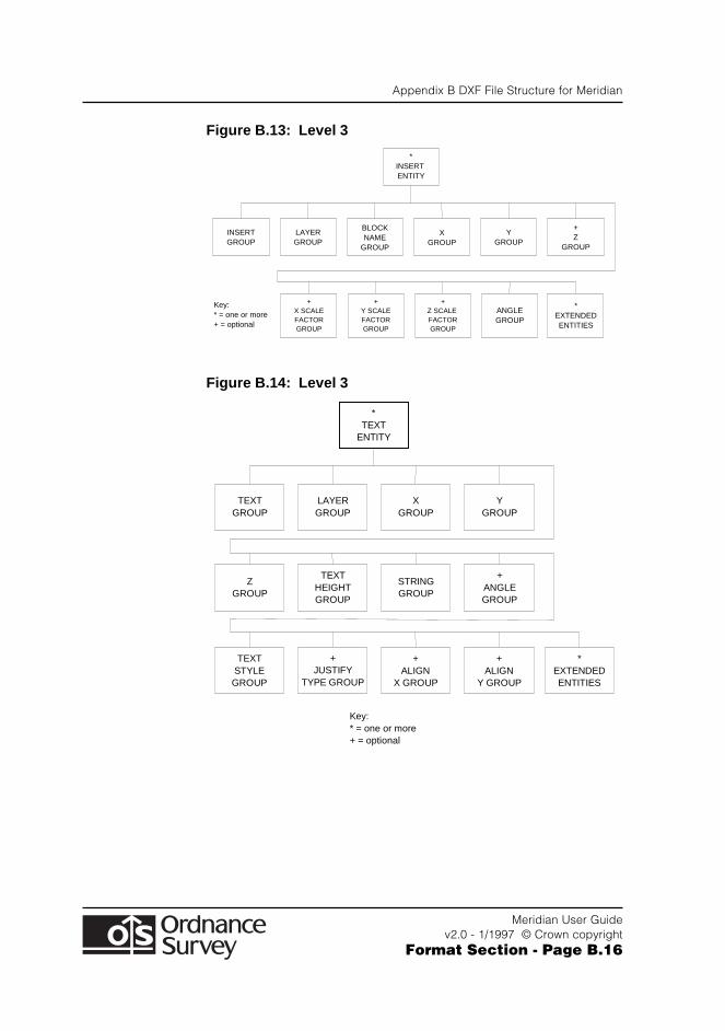
Appendix B DXF File Structure for Meridian
Meridian User Guidev2.0 - 1/1997 © Crown copyright
Format Section - Page B.16
Figure B.13: Level 3
* INSERT ENTITY
INSERT GROUP
LAYER GROUP
BLOCK NAME
GROUP
X GROUP
Y GROUP
+ Z
GROUP
+ X SCALE FACTOR GROUP
+ Y SCALE FACTOR GROUP
+ Z SCALE FACTOR GROUP
ANGLE GROUP
Key: * = one or more + = optional
* EXTENDED ENTITIES
Figure B.14: Level 3
* TEXT
ENTITY
TEXT GROUP
LAYER GROUP
X GROUP
Y GROUP
Z GROUP
TEXT HEIGHT GROUP
STRING GROUP
+ ANGLE GROUP
TEXT STYLE GROUP
+ JUSTIFY
TYPE GROUP
+ ALIGN
X GROUP
+ ALIGN
Y GROUP
Key: * = one or more + = optional
* EXTENDED ENTITIES
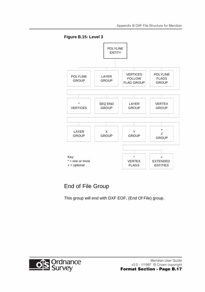
Appendix B DXF File Structure for Meridian
Meridian User Guidev2.0 - 1/1997 © Crown copyright
Format Section - Page B.17
Figure B.15: Level 3
POLYLINE GROUP
LAYER GROUP
VERTICES FOLLOW
FLAG GROUP
POLYLINE FLAGS GROUP
* VERTICES
SEQ END GROUP
LAYER GROUP
VERTEX GROUP
LAYER GROUP
X GROUP
Y GROUP
+ Z
GROUP
+ EXTENDED
ENTITIES
POLYLINE ENTITY
Key: * = one or more + = optional
* VERTEX FLAGS
End of File Group
This group will end with DXF EOF, (End Of File) group.

Appendix B DXF File Structure for Meridian
Meridian User Guidev2.0 - 1/1997 © Crown copyright
Format Section - Page B.18