members in compression - iv
TRANSCRIPT

7/29/2019 Members in Compression - IV
http://slidepdf.com/reader/full/members-in-compression-iv 1/38
Compression Members

7/29/2019 Members in Compression - IV
http://slidepdf.com/reader/full/members-in-compression-iv 2/38
COLUMN STABILITY
A. Flexural Buckling
• Elastic Buckling
•Inelastic Buckling
• Yielding
B. Local Buckling – Section E7 pp 16.1-39
and B4 pp 16.1-14
C. Lateral Torsional Buckling

7/29/2019 Members in Compression - IV
http://slidepdf.com/reader/full/members-in-compression-iv 3/38
AISC Requirements
CHAPTER E pp 16.1-32
Nominal Compressive Strength
g cr n A F P
AISC Eqtn E3-1

7/29/2019 Members in Compression - IV
http://slidepdf.com/reader/full/members-in-compression-iv 4/38
AISC Requirements
LRFD
ncu P P
loadsfactoredof Sumu P
strengthecompressivdesignnc P
0.90ncompressiofor factor resistance c

7/29/2019 Members in Compression - IV
http://slidepdf.com/reader/full/members-in-compression-iv 5/38
Design Strength

7/29/2019 Members in Compression - IV
http://slidepdf.com/reader/full/members-in-compression-iv 6/38
In Summary
877.0
44.0or
71.4658.0
otherwise F
F F
F
E
r
KLif F
F
e
ye
y
y F
F
cr
e
y
200
r
KL

7/29/2019 Members in Compression - IV
http://slidepdf.com/reader/full/members-in-compression-iv 7/38
Local Stability - Section B4 pp 16.1-14
Local Stability: If elements of cross section are thin LOCAL buckling occurs
The strength corresponding to any buckling mode cannot be developed

7/29/2019 Members in Compression - IV
http://slidepdf.com/reader/full/members-in-compression-iv 8/38
Local Stability - Section B4 pp 16.1-14
Local Stability: If elements of cross section are thin LOCAL buckling occurs
The strength corresponding to any buckling mode cannot be developed

7/29/2019 Members in Compression - IV
http://slidepdf.com/reader/full/members-in-compression-iv 9/38
Local Stability - Section B4 pp 16.1-14
• Stiffened Elements of Cross-Section
• Unstiffened Elements of Cross-Section

7/29/2019 Members in Compression - IV
http://slidepdf.com/reader/full/members-in-compression-iv 10/38
Local Stability - Section B4 pp 16.1-14
• Compact
– Section Develops its full plastic stress before buckling
(failure is due to yielding only)
• Noncompact – Yield stress is reached in some but not all of its compression elements
before buckling takes place
(failure is due to partial buckling partial yielding)
• Slender – Yield stress is never reached in any of the compression elements
(failure is due to local buckling only)

7/29/2019 Members in Compression - IV
http://slidepdf.com/reader/full/members-in-compression-iv 11/38
Local Stability - Section B4 pp 16.1-14
If local buckling occurs cross section is not fully effective Avoid whenever possible
Measure of susceptibility to local buckling
Width-Thickness ratio of each cross sectional element: l
If cross section has slender elements - l lr
Reduce Axial Strength (E7 pp 16.1-39 )

7/29/2019 Members in Compression - IV
http://slidepdf.com/reader/full/members-in-compression-iv 12/38
Slenderness Parameter - Limiting Values
AISC B5 Table B4.1
pp 16.1-16

7/29/2019 Members in Compression - IV
http://slidepdf.com/reader/full/members-in-compression-iv 13/38
Slenderness Parameter - Limiting Values
AISC B5 Table B4.1
pp 16.1-17

7/29/2019 Members in Compression - IV
http://slidepdf.com/reader/full/members-in-compression-iv 14/38
Slenderness Parameter - Limiting Values
AISC B5 Table B4.1
pp 16.1-18

7/29/2019 Members in Compression - IV
http://slidepdf.com/reader/full/members-in-compression-iv 15/38
Slender Cross Sectional Element:
Strength Reduction E7 pp 16.1-39
Reduction Factor Q:
Q: B4.1 – B4.2 pp 16.1-40 to 16.1-43
877.0
44.0or
71.4658.0
otherwise F
QF F
QF
E
r
KLif QF
F
e
ye
y y
F
QF
cr
e
y

7/29/2019 Members in Compression - IV
http://slidepdf.com/reader/full/members-in-compression-iv 16/38
Slender Cross Sectional Element:
Strength Reduction E7 pp 16.1-39
Reduction Factor Q:
Qs, Qa: B4.1 – B4.2 pp 16.1-40 to 16.1-43
877.0
44.0or
71.4658.0
otherwise F
QF F
QF
E
r
KLif F
F
e
ye
y
y F
QF
cr
e
y
Q=QsQa

7/29/2019 Members in Compression - IV
http://slidepdf.com/reader/full/members-in-compression-iv 17/38
COLUMN STABILITY
A. Flexural Buckling
• Elastic Buckling
•
Inelastic Buckling• Yielding
B. Local Buckling – Section E7 pp 16.1-39
and B4 pp 16.1-14
C. Torsional, Lateral/Torsional Buckling

7/29/2019 Members in Compression - IV
http://slidepdf.com/reader/full/members-in-compression-iv 18/38
Torsional & Flexural Torsional Buckling
When an axially loaded member becomes unstable overall
(no local buckling) it buckles one of the three ways
• Flexural Buckling
• Torsional Buckling
• Flexural-Torsional
Buckling

7/29/2019 Members in Compression - IV
http://slidepdf.com/reader/full/members-in-compression-iv 19/38
Torsional Buckling
Twisting about longitudinal axis of member Only with doubly symmetrical cross sections with slender cross-
sectional elements
Standard Hot-Rolled Shapes are
NOT susceptible
Built-Up Members should be
investigated
Cruciform shape particularly
vulnerable

7/29/2019 Members in Compression - IV
http://slidepdf.com/reader/full/members-in-compression-iv 20/38
Flexural Torsional Buckling
Combination of Flexural and Torsional BucklingOnly with unsymmetrical cross sections
1 Axis of Symmetry: channels, structuraltees, double-angle, equal
length single angles
No Axis of Symmetry: unequal length singleangles

7/29/2019 Members in Compression - IV
http://slidepdf.com/reader/full/members-in-compression-iv 21/38
Torsional Buckling
y x z
we
I I GJ L K
EC F
12
2 Eq. E4-4
Cw = Warping Constant (in6)
Kz = Effective Length Factor for Torsional Buckling
(based on end restraints against twisting)
G = Shear Modulus (11,200 ksi for structural steel)
J = Torsional Constant

7/29/2019 Members in Compression - IV
http://slidepdf.com/reader/full/members-in-compression-iv 22/38
Lateral Torsional Buckling 1-Axis of Symmetry
24
112 ez ey
ez eyez ey
e F F
H F F
H
F F F AISC Eq. E4-5
22
y y
eyr L K
E F
22
21
o g z
wez
r AGJ
L K
EC F
2
22
1o
oo
r
y x H g
y xooo
A I I y xr
222
oo y x , Coordinates of shear center w.r.t centroid of section

7/29/2019 Members in Compression - IV
http://slidepdf.com/reader/full/members-in-compression-iv 23/38
Lateral Torsional Buckling No Axis of Symmetry
0
2
2
2
2
o
oexee
o
oeyee
ez eeyeexe
r
y F F F
r x F F F
F F F F F F
AISC Eq. E4-6
Fe is the lowest root of the
Cubic equation

7/29/2019 Members in Compression - IV
http://slidepdf.com/reader/full/members-in-compression-iv 24/38
In Summary - Definition of F e
Elastic Buckling Stress corresponding to the controlling mode of
failure (flexural, torsional or flexural torsional)F
e :
Theory of Elastic Stability (Timoshenko & Gere 1961)
Flexural Buckling Torsional Buckling
2-axis of symmetry
Flexural Torsional
Buckling
1 axis of symmetry
Flexural Torsional
Buckling
No axis of symmetry
22
/ r KL E F e AISC Eqtn
E4-4AISC EqtnE4-5
AISC EqtnE4-6
7/29/2019 Members in Compression - IV
http://slidepdf.com/reader/full/members-in-compression-iv 25/38
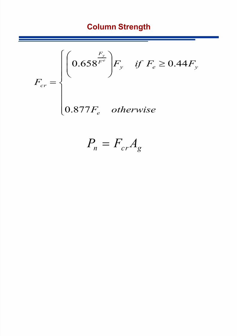
Column Strength
877.0
44.0658.0
otherwise F
F F if F
F
e
ye y F
F
cr
e
y
g cr n A F P

7/29/2019 Members in Compression - IV
http://slidepdf.com/reader/full/members-in-compression-iv 26/38
EXAMPLE
Compute the compressive strength of a WT12x81 of A992 steel.
Assume (K xL) = 25.5 ft, (K yL) = 20 ft, and (K z L) = 20 ft
20043.8750.3
125.25
x
x
r
L K
r
KL
OK
43.8711350
000,2971.471.4
y F
E
ksi44.3743.87
000,292
2
2
2
r KL
E
F e
ksi59.28)50(658.0658.0 44.37
50
y
F
F
cr F F e
y
Inelastic Buckling
FLEXURAL Buckling – X axis
WT 12X81
Ag=23.9 in2
r x=3.50 in
r y=3.05 in
kips3.683)9.23(59.28 g cr n
A F P

7/29/2019 Members in Compression - IV
http://slidepdf.com/reader/full/members-in-compression-iv 27/38
EXAMPLE
20069.7805.3
1220
y
y
r
L K OK
ksi22.46
69.78
000,292
2
2
2
y y
eyr L K
E F
FLEXURAL TORSIONAL Buckling – Y axis (axis of symmetry)
WT 12X81
Ag=23.9 in2
r x=3.50 in
r y=3.05 in
y=2.70 in
tf =1.22 in
Ix=293 in4
Iy=221 in4
J=9.22 in4
Cw=43.8 in6
00 x
20
f t y y
87.259.23
221293)09.2(02
222
g
y x
ooo A
I I
y xr
Shear Center

7/29/2019 Members in Compression - IV
http://slidepdf.com/reader/full/members-in-compression-iv 28/38
EXAMPLE
FLEXURAL TORSIONAL Buckling – Y axis (axis of symmetry)
WT 12X81
Ag=23.9 in2
r x=3.50 in
r y=3.05 in
y=2.70 in
tf =1.22 in
Ix=293 in4
Iy=221 in4
J=9.22 in4
Cw=43.8 in6
ksi
r AGJ
L K EC F
o g z
wez
4.16787.259.23
1)22.9(200,11
1220
)8.43)(000,29(
1
22
2
22
2

7/29/2019 Members in Compression - IV
http://slidepdf.com/reader/full/members-in-compression-iv 29/38
EXAMPLE
FLEXURAL TORSIONAL Buckling – Y axis (axis of symmetry)
WT 12X81
Ag=23.9 in2
r x=3.50 in
r y=3.05 in
y=2.70 in
tf =1.22 in
Ix=293 in4
Iy=221 in4
J=9.22 in4
Cw=43.8 in6
ksi
F F
H F F
H
F F F
ez ey
ez eyez ey
e
63.53
4.16722.46
8312.04.16722.46411
8312.02
4.16722.46
411
2
2
8312.0
87.25
090.2011
2
2
22
o
oo
r
y x H

7/29/2019 Members in Compression - IV
http://slidepdf.com/reader/full/members-in-compression-iv 30/38
EXAMPLE
FLEXURAL TORSIONAL Buckling – Y axis (axis of symmetry)
WT 12X81
Ag=23.9 in2
r x=3.50 in
r y=3.05 in
y=2.70 in
tf =1.22 in
Ix=293 in4
Iy=221 in4
J=9.22 in4
Cw=43.8 in6
Elastic or Inelastic LTB?
63.430.22)50(44.044.0
e y F ksi F
877.0
44.0658.0
otherwise F
F F if F
F
e
ye y F
F
cr
e
y

7/29/2019 Members in Compression - IV
http://slidepdf.com/reader/full/members-in-compression-iv 31/38
EXAMPLE
FLEXURAL TORSIONAL Buckling – Y axis (axis of symmetry)
WT 12X81
Ag=23.9 in2
r x=3.50 in
r y=3.05 in
y=2.70 in
tf =1.22 in
Ix=293 in4
Iy=221 in4
J=9.22 in4
Cw=43.8 in6
ksi
F F y F
F
cr
e
y
59.2850658.0
658.0
63.43
50
kips7.739)70.2(95.30 g cr n A F P
Compare to FLEXURAL Buckling – X axis
kips3.683)9.23(82.21 g cr n A F P

7/29/2019 Members in Compression - IV
http://slidepdf.com/reader/full/members-in-compression-iv 32/38
Column Design Tables
Assumption : Strength Governed by Flexural Buckling
Check Local Buckling
Column Design Tables
Design strength of selected shapes for effective length KL
Table 4-1 to 4-2, (pp 4-10 to 4-316)
Critical Stress for Slenderness KL/r
table 4.22 pp (4-318 to 4-322)

7/29/2019 Members in Compression - IV
http://slidepdf.com/reader/full/members-in-compression-iv 33/38
EXAMPLE
Compute the available compressive strength of a W14x74 A992 steel
compression member. Assume pinned ends and L=20 ft. Use (a) Table 4-
22 and (b) column load tables
(a) LRFD - Table 4-22 – pp 4-318
20077.9648.2
)12)(20)(1(Maximum
yr
KL
r
KL
Table has integer values of (KL/r) Round up or interpolate
Fy=50 ksi
ksi P cr 67.22
ksi A P P g cr n 494)8.21(67.22

7/29/2019 Members in Compression - IV
http://slidepdf.com/reader/full/members-in-compression-iv 34/38
EXAMPLE
Compute the available compressive strength of a W14x74 A992 steel
compression member. Assume pinned ends and L=20 ft. Use (a) Table 4-
22 and (b) column load tables
(b) LRFD Column Load Tables
f t KL 20)20)(1(Maximum
Tabular values based on minimum radius of gyration
Fy=50 ksi
kips P nc 494

7/29/2019 Members in Compression - IV
http://slidepdf.com/reader/full/members-in-compression-iv 35/38
Example II
A W12x58, 24 feet long in pinned at both ends and braced in the weak
direction at the third points. A992 steel is used. Determine available
compressive strength
20025.3851.2
)12)(8(1
y
y
r
L K
20055.54
28.5
)12)(24(1
x
x
r
L K
Enter table 4.22 with KL/r=54.55 (LRFD)
28.5 xr
51.2 yr ksi P cr 24.36
kips
A P P g cr n
616
)17(24.36
17 g A

7/29/2019 Members in Compression - IV
http://slidepdf.com/reader/full/members-in-compression-iv 36/38
Example II
A W12x58, 24 feet long in pinned at both ends and braced in the weak
direction at the third points. A992 steel is used. Determine available
compressive strength
20025.3851.2
)12)(8(1
y
y
r
L K
20055.54
28.5
)12)(24(1
x
x
r
L K
Enter table 4.22 with KL/r=54.55 (ASD)
28.5 xr
51.2 yr
ksi F
c
cr 09.24
kips A
F P
g c
cr
c
n
410
17 g A

7/29/2019 Members in Compression - IV
http://slidepdf.com/reader/full/members-in-compression-iv 37/38
Example II
A W12x58, 24 feet long in pinned at both ends and braced in the weak
direction at the third points. A992 steel is used. Determine available
compressive strength
20025.3851.2
)12)(8(1
y
y
r
L K
20055.5428.5
)12)(24(1
x
x
r
L K CAN I USE Column Load Tables?
y x
x
r r
L K KL
Not Directly because they are
based on min r (y axis buckling)
If x-axis buckling enter table with

7/29/2019 Members in Compression - IV
http://slidepdf.com/reader/full/members-in-compression-iv 38/38
Example II
A W12x58, 24 feet long in pinned at both ends and braced in the weak
direction at the third points. A992 steel is used. Determine available
compressive strength
20025.3851.2
)12)(8(1
y
y
r
L K
20055.5428.5
)12)(24(1
x
x
r
L K X-axis buckling enter table with
ft r r
L K KL
y x
x 43.111.2
)24)(1(
kips P n 616