compression members with hollow sections and concentric
TRANSCRIPT

Proceedings of the Annual Stability Conference
Structural Stability Research Council St. Louis, Missouri, April 16-20, 2013
Compression Members with Hollow Sections and Concentric Slotted Gusset Plates – Behavior and Recommended Design Model
H. Unterweger1, A. Taras2
Abstract In practical applications, compression members in trusses or bracing systems are often composed of hollow sections with slotted gusset plates on both ends. Either a bolted connection with splice plates on both sides or a welded connection are used to achieve a concentric configuration. In recent application cases, members of this type were designed with unusually long gusset plates at their ends, leading to reduced load bearing capacities. In the present paper, the load carrying behavior of such members is shown by means of realistic numerical calculations. The resulting compression member capacities are compared with the design models for flexural buckling as they are commonly employed in practice. It will be shown that these models significantly overestimate the compression member capacity – particularly in cases with low slenderness. Interestingly, imperfection forms similar to the second eigenmode often lead to the most critical design situation. The influence of residual stresses due to the welding of the gusset plate to the slotted hollow section is also studied in detail. On the basis of these numerical results, an improved engineering design recommendation for the practical verification of the gusset plate stability could be developed, which should be used in addition to the conventional member buckling verification. 1. Introduction and motivation for a comprehensive study Members in trusses as well as members of bracings are often designed with hollow sections (rectangular – RHS or circular – CHS) and slotted gusset plates on both ends. Either a bolted connection with splice plates on both sides or a welded connection are used to achieve a concentric configuration. Two typical examples are shown in Fig. 1.
1 Full Professor, Graz University of Technology, <[email protected]> 2 Assistant Professor, Graz University of Technology, <[email protected]>
19

A boltedis also vdependi
Fig. 2 apinned eclamped The autwith slolacks a cmust bepredomibuckling
Figure
d connectiovisible in Fing on the m
also shows tend must bed support is
thors’ motivotted gusset comprehense pointed oinant, whicg of the gus
e 1: Examples
on leads to aFig. 1. Basemember dept
Figure 2:
the two limie assumed, wpresent. On
vation for aplates was
sive analyticout that for ch can alsosset plate.
for member j
a greater lend on a studth h, are giv
Studied RHS
iting cases fwhereas in nly these tw
a comprehegiven by th
cal and numthese hollo
o be interpr
oints – welded
ngth L1, witdy of commven in Fig. 2
– member joi
for memberFig. 2b – a o cases are
nsive studyhe fact that merical studyow sectionsreted as an
d and bolted, r
th reduced bmon detailing2.
ints; a.) bolted
r support ouconnection studied in d
y of the behthe literatury dealing ws out of plan interaction
respectively (f
bending stifg solutions,
d, b.) welded
ut of plane. to a concre
detail.
havior of core – to the a
with bucklingane flexuran of global
from [1])
ffness out of, usual valu
In Fig. 2a iete wall –a p
ompression authors’ knog of such mal buckling l buckling
f plane, as ues for L1,
n axis I, a practically
members owledge –
members. It is always and local
20

Within the literature, a lot of studies are available dealing with the load transfer from the gusset plate to the hollow section (e.g. Zhao R. (2009) and references there), however the focus is placed on tension applications, excluding buckling phenomena. In past detailing practice, the buckling resistance was sufficiently warranted by performing a buckling check for the hollow section itself, since the gusset plates were usually very short and had a negligible effect on the buckling length and/or were not the subject to significant second-order out of plane bending. However, more recent detailing practice led to free lengths L1 of the gusset plates that are significantly larger than old design tradition. As will be shown in the following, the limited cross-sectional bending capacity of the gusset plate can also lead to a significant reduction of the overall compression strength of the member. Only for very slender members a conventional buckling verification – even when taking account of the potentially increased buckling length due to the reduced bending stiffness in the joint region – is sufficient to guarantee structural safety. If, in addition to a long gusset plate, an eccentric joint configuration is chosen (e.g. directly bolted without splice plates) a further, significant reduction of the member compression capacity is observed. In this case design recommendations are given in Unterweger (2010). 2. Simplifications and parameter range of the study In order to study the load bearing capacity of hollow sections with slotted gusset plates on both ends, some simplifications were introduced, shown in Fig. 3. In this figure, the studied geometry with the chosen symbols and notations is presented as well. The two studied border cases for boundary conditions of the gusset plate are: - pinned (BC1) and, - fully clamped (BC2) ends, with rigid support out of plane (in both cases). In the study described here, squared hollow sections were analyzed, ignoring the fillets at the edges (b = h) and leading to the area A0, second moment of area Jz0 and radius of gyration rz0. However, the final results can be shown to also be valid for rectangular and circular hollow sections. The free length L1 of the gusset plate was varied between L1 = 1,0 · h ÷ 2,0 · h. The height of the gusset plate h1 was fixed with h1 = 1,3 · h, which is typical for practical applications. The slotted length Ls, which was chosen to be Ls = 1,75 · h, is of great significance and represents a minimum value: this length is at least necessary in order to utilize the full axial and bending capacity of the member at the end of the gusset plate, due to the load introduction from the gusset plate into the hollow section. This was also verified within the comprehensive FEM-study, which will be presented in section 4.
21

2.1 ReleThe bucplate (I1
Based oused in member
In pract Another÷ 0,10 i 2.2 LoadIn this swere tak
Figure 3: S
evant stiffneckling capac1 according t
on the assumEurope for
r respectivel
ice, A1 ~ A
r important s often valid
ding of the mstudy, only ken into acc
Sketch of studi
ess ratio I1/Icity of the mto Eq. 1) an
med geometr the stiffnely; A0 = are
A0 is often va
parameter id.
member constant ax
count, based
ied joint confi
I0 and membmember str
nd member (
try of the gess ratio I1/Iea of the mem
4,
alid leading
is the memb
xial compred on execut
iguration; geom
ber length rarongly depe(I0 = Iz0)
∙
gusset platesI0, Eq. (2) imber, A1 =
68 ∙ ∙
g to very sm
ber length r
ession forcetion toleranc
metry and ide
atio L1/L0 nds on the
s (h1 = 1,3 is valid (h =area of the
all stiffness
atio L1/L0. F
es are consices. The eff
alized bounda
stiffness ra
· h) and qu= depth andgusset plate
ratios of ab
For practica
idered. Geofect of resid
ary conditions
tio I1/I0 of t
uadratic RHd t = thickne)
bout I1/I0 ~ 0
al cases, L1/
ometric impdual stresses
the gusset
(1)
S-sections ness of the
(2)
0,01.
/L0 = 0,05
perfections s was also
22

studied,and gus 3. Buck 3.1 BuckDue to (length bendingused. Thbuckling2 repla
Figu The relathe well
In the lifactors (DimitroanalyticUnterwe For pracup in Fiare plott
in particulset plate.
kling verific
kling verificthe significL1), for th
g stiffness Iz
his is illustrg mode is re
aces Lcr,1 cal
ure 4: a.) First
ationship bel known Eq.
iterature, a i and ideaov (1953),
cal formulaeger, Taras
ctical applicig. 5. In theted for I = 0
ar those res
cation in pr
cation in praantly reduce buckling
z,0 over the wrated in Fig.elevant for tlculated with
t and b.) secon
etween effec. (3)
number of al buckling also found
s for the s(2011).
cations, all se figures, t
0,01 , 0,02 a
sidual stress
ractice and
actice ced bending
verificationwhole length. 4. For memthe ultimateh 1.
nd bifurcation
ctive length
analytic forloads Ncr,i
d in Petersestudied cas
the relevantthe paramet
and 0,04, cov
ses caused b
danger of o
stiffness ofn of the meh L0 – an inmbers with e buckling st
buckling mod
and ideal b
,∙ ∙
∙
rmulas for ai can be foen (1982)),ses (see Fig
t results forter I is equavering all pr
by the weld
overestima
f the gussetember out
ncreased effeslotted gusstrength of th
de shapes and t
uckling load
an iterative und (Pflüge, lead to vg. 4) are s
r the effectial to the stiffractical case
ded connect
tion of mem
t plate at thof plane – ective lengthset plates, she member,
the associated
d Ncr for ea
solution foer (1964)).
very unsafe summed up
ve length faffness ratio (es.
tion between
mber capac
he end of thbased on a
h Lcr = · Lsometimes t so that Lcr,2
d equivalent co
ch mode i is
or the effectSimplified results. Ap
p by the a
actors i are(I = I1/I0). T
n member
city
e member a constant L0 must be the second 2 based on
olumns
s given by
(3)
ive length solutions
ppropriate authors in
e summed The results
23

Figure
3.2 OveBefore section, bucklingover wh Fig. 6 shsimply order thincreasewell-kno
Makingstrengthlike the member
e 5: Factors i
erestimationall the detaa simplifi
g behavior hole length L
hows an altesupported m
heory, the ined deformatown second
use of theh of the mem
Eurocode (r as the one
i for the determm
of the buckails and resed examplewhen compL0).
ernative appmember. Banternal forcetion w depend-order elast
(elastic) mmber can b2012), givegiven by th
mination of bumember for, a.)
kling strengtsults of thee is shown,pared to a si
proach for thased on an ees at the relends on the tic amplifica
member capae determine
e formulas fohe buckling
uckling lengths) pinned ends
th of a mem comprehen, in order timply suppo
he calculatiequivalent ievant sectioactual load ation factor
⁄
acity in sectied analyticaor eequ that lcurves codi
s (1st and 2nd band b.) fixed e
ber with slonsive studyto emphasiorted const
on of the ulimperfection
on m (N = PP and the ifII in Eq. (4
ion m (max
ally from selead to the sfied in the s
buckling modeends
otted gusset are presenize the signtant-section
ltimate compn eequ and a
P, M = P · wdeal bucklin
4).
x = Fy), the uecond-order same comprsame standa
e) using the eq
plate nted in the nificant diffn member (s
pression strapplication w) are calcung load Pcr,
ultimate comtheory. Som
ression strenard.
quivalent
following ference in section Iz,0
rength of a of second
ulated. The using the
(4)
mpression me codes,
ngth of the
24

Figure 6: Compressive Strength of a column – alternative approach
Based on the second order theory approach in Fig. 6, it is now possible to show the utilization of the relevant gusset-plate section capacity in axis 1. In Fig. 7, a typical example of a hollow section member (RHS: h = b = 200, t = 10 mm) of length L0 = 8000 mm is shown. The member compression strength of Pn = 840 kN given in Fig. 7a is based on the proposed verification in Fig. 4, using the effective length factors 1 in Fig. 5 and the buckling curve a of the Eurocode (2012). The shape of the imperfections is based on the 1st buckling eigenmode (simplified in a sine-wave form) in Fig. 7a and on the 2nd mode (simplified, with eequ in section 1 of Fig. 7) in Fig. 7b. When the load is thus set equal to the theoretical resistance Pn = 840 kN, only the hollow member has sufficient section capacity. In the gusset plate section 1 – particularly for the imperfections based on the 2nd mode – the utilization factors UF1 are significantly higher than 1, and this even if the increased plastic section capacity is used (UF1,pl). This means that the compression strength based on the buckling verification of the member with increased, equivalent buckling length (see Fig. 4) significantly overestimates the buckling capacity of the member with slotted gusset plates, because the gusset plate section 1 (and not the mid-span cross-section of the HS member) determines the ultimate capacity, as well as the fact that imperfections based on the 2nd mode must also be considered.
25
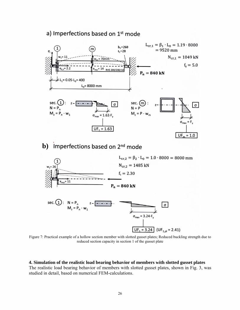
Figure 7: Practical example of a hollow section member with slotted gusset plates; Reduced buckling strength due to
reduced section capacity in section 1 of the gusset plate 4. Simulation of the realistic load bearing behavior of members with slotted gusset plates The realistic load bearing behavior of members with slotted gusset plates, shown in Fig. 3, was studied in detail, based on numerical FEM-calculations.
h1=260 t1=28
b)
26

4.1 FEMThe numFEM-mwas choelementthe joinwelds bexecutiooutside element The bouof plane Within section In all cachosen, A0 · Fy were sel
4.2 LineFor eaclinear cathe selec
M-model merical calc
model at the osen. The gts with linea
nt region wabetween theon of butt wthe joint wa
ts.
undary conde.
the calculatRHS 200/20
alculations, with a yield= 1.786 kNlected.
Figu
ear bucklingh studied malculations, cted geomet
culations wemember en
gusset platear interpolatas modeled gusset plat
welds. The sas modeled
ditions in ax
tions memb00/10 mm w
a linear elad stress Fy =
N. An elastic
ure 8: FEM nu
g Analyses member, a
due to the tric imperfe
ere done witnd is showns were modtion functionusing shell te and mem
sealing plated using beam
xis I were b
ber lengths owithout fille
astic-ideal p= 235 N/mmc modulus o
umerical mode
linear buckfact that th
ections (1st a
th the Finiten. A combindeled using ns over the elements w
mber are noes (see Fig. m elements
based on the
of L0 = 4,8 ets (leading t
plastic materm². This leaof E = 210.0
el for the calcu
kling analyshe calculatedand 2nd mod
e Element Snation of vovolume ele
gusset platewith 20 elemot modeled
1, 3) were with a rigid
e studied ca
and 12 m to A0 = 760
rial behaviods to an ulti
000 N/mm²
ulation of the l
ses (LBA) wd buckling m
de studied).
Software ABolume, shelements withe thickness. ments for eain detail, imomitted. Th
d kinematic
ases, pinned
were consid00 mm², rz0 =
our without imate sectioand a Poiss
oad bearing ca
was performmodes also
BAQUS. In ll and beamh eight isopThe RHS-m
ach section mplying mehe rest of th
coupling to
or fully cla
dered with = 78 mm).
strain-hardeon capacity son’s ratio o
apacity
med prior toformed the
Fig. 8 the m elements parametric member in wall. The
eaning the he member o the shell
amped out
a member
ening was of N0,pl =
of = 0,3
o the non-e basis for
27

Fig. 9 shas well a The comcalculatoverestiintroducbending Based oincreasebasis of = h/5. Tused (ne
Figure
4.3 RealFor the plates, imperfe In a firselectedmaximuEN 109eigenmo
hows the firas fully clam
mparison oted using bimation by ction from tg stiffness pa
on a compree the – comf beam-theorThis leads toew paramete
9: Different b
listic comprcalculationa series ctions) was
st step, LBd for the impum value of 90-2 (2008) ode shapes.
rst and secomped ends o
f the ideal beam-theory
the latter.the gusset partially inef
ehensive stumputational -
retical metho an increaseer L1
*/L0).
buckling mode
ression loadn of realisticof GMNIAcarried out
BA-analysesperfection s
f the imperfenow used
ond bucklingof the gusse
buckling ly (Eq. (3) . This is uplate to the ffective, lead
udy by the a- free lengthhods such ased length L
es (FEM-Modeplate 2
d bearing bec compressiA-analyses t.
were perfoshape along
fection chosein Europe,
g modes foret plate.
oads Ncr,i bwith effec
understandamember, mding to an o
authors, it ih of the guss the one rep1
* = L1 + h/
el) for a memb260/28; L1 = 4
ehaviour ion strength(geometric
ormed. Theg the membeen with e0,m
which give
r a member
based on thctive length
able as a cmaking the f
verestimatio
is suggestedsset plate Lpresented by/5 if the effe
ber with L0 = 400 mm)
h values of c and mat
e calculateder. These sh
max = L0/750es measurem
with L0 = 8
he LBA anah factors oconsequencfirst portion on of Ncr,i.
d - for practL1 (used to dy Fig. 5 ) byective length
8 m (Profile R
the membeterial nonli
d eigenmodehapes were
0, based on tments that
000 mm an
alyses withof Fig. 5) e of the l of the RHS
tical applicadetermine Ny a distance h factors of
RHS 200/200/1
er with slottinear analy
es (1st and then scaled
the code of are relevan
nd pinned
h the ones shows a
local load S member
ations - to Ncr,i on the L1 = b/5
f Fig. 5 are
10; gusset
ted gusset yses with
2nd) were d, with the
execution nt for both
28
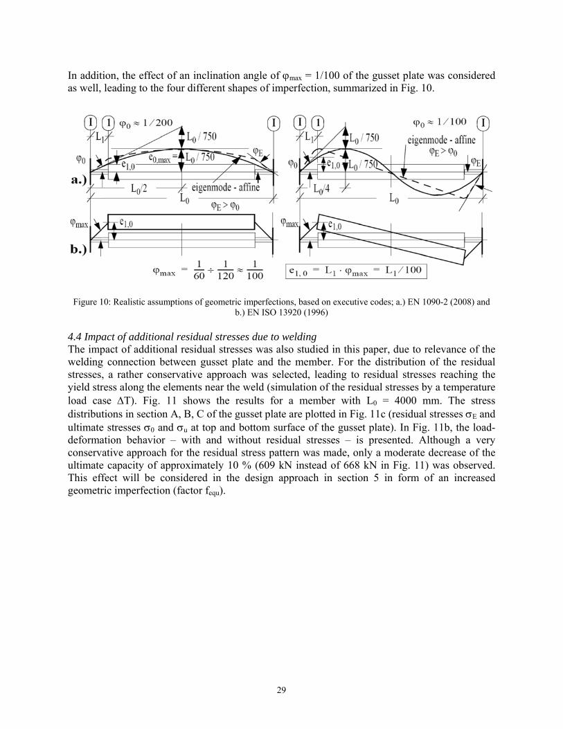
In additas well,
Figure 1
4.4 ImpaThe impweldingstressesyield strload cadistributultimatedeformaconservultimateThis effgeometr
tion, the effeleading to t
10: Realistic a
act of additpact of addig connection, a rather cress along thase T). Fitions in secte stresses 0
ation behavvative approe capacity offect will beric imperfec
fect of an inthe four diff
ssumptions of
ional residuitional residn between gonservativehe elementsig. 11 showtion A, B, C0 and u at
vior – with ach for the
of approxime considerection (factor
nclination anferent shape
f geometric imb.) E
ual stresses dual stressesgusset plate
e approach ws near the wews the resuC of the guss
top and botand witho
residual strmately 10 % ed in the der fequ).
ngle of max
es of imperf
mperfections, bEN ISO 13920
due to welds was also ste and the mwas selecteeld (simulatults for a mset plate arettom surface
out residual ress pattern
(609 kN inesign appro
x = 1/100 offection, sum
based on execu (1996)
ding tudied in th
member. Fored, leading ttion of the rmember wie plotted in Fe of the gus
stresses –was made,
nstead of 66oach in sec
f the gusset mmarized in F
utive codes; a.
his paper, dur the distribto residual
residual streith L0 = 40Fig. 11c (ressset plate). I
is presenteonly a mod
68 kN in Fition 5 in f
plate was cFig. 10.
.) EN 1090-2 (
ue to relevabution of thstresses reasses by a te000 mm. Tsidual stressIn Fig. 11b,ed. Althougderate decreig. 11) was form of an
considered
(2008) and
ance of the he residual aching the mperature
The stress ses E and , the load-gh a very ease of the
observed. increased
29

Figure 11
5. SuggBased oplates, tmodel, s 5.1 Desplate As showto the lim The mamemberat the e“realisti Startingin Fig. 1factor fI
e1,0 · fII) In additdescendincreaselinear) p
1: Load bearin
estion of a on the resuthe authors summed up
ign model fo
wn for the emited sectio
ain idea of tr with pinneend of the mic” behaviou
g from the ge12) increaseII that accou.
tion, the sding lines, les (due to adplastic and t
ng capacities aends (geome
design modlts of the Gdeveloped ain section 5
for compress
xample in Fon capacity
the design med ends. Thmember (seur, determin
eometric imes followingunts for the c
section capleading to dditional mothe (too low
and consideredtric imperfecti
del for pracGMNA-calca simple de5.2, will be
sive strength
Fig. 7, the cof the gusse
model, basee plot showection 1) wned by GMN
mperfection eg the elasticcorrect idea
pacity of threduced axoment MII =
w) linear-ela
d residual stresions based on
ctical applicculations fosign model shown in th
h considerin
ompressive et plate in it
ed on 2nd orws the deformwith increasiNIA-calcula
e1,0 at the mc 2nd order aal buckling l
he gusset plxial load ca= N · U3). Aastic cross-s
sses E for a mthe 1st bucklin
cation or the studie
for practicahe following
ng the limite
strength ofts cross-sect
rder theory,mation U3 (ing axial loations.
member end amplificationload Pcr, nea
late is alsoarrying capaAs border linsectional cap
member with Lng mode shap
ed memberal design. Thg.
ed section c
f the membetion 1.
, is summed(out-of-plan
oad N. The
in section 1n factor givarly up to th
representeacites N if nes the (toopacity curve
L0 = 4000 mme)
s with slotthe backgrou
capacity of th
er is often li
d up in Figne) in the gu
circles rep
, the deformven by Eq. (he ultimate l
ed in Fig. 1f the deformo high) fullyes for the re
m and pinned
ted gusset und of this
he gusset
imited due
g. 12 for a usset plate resent the
mation (U3 4), i.e. the load (U3 =
12 by the mation U3 y (i.e. non-ectangular
30
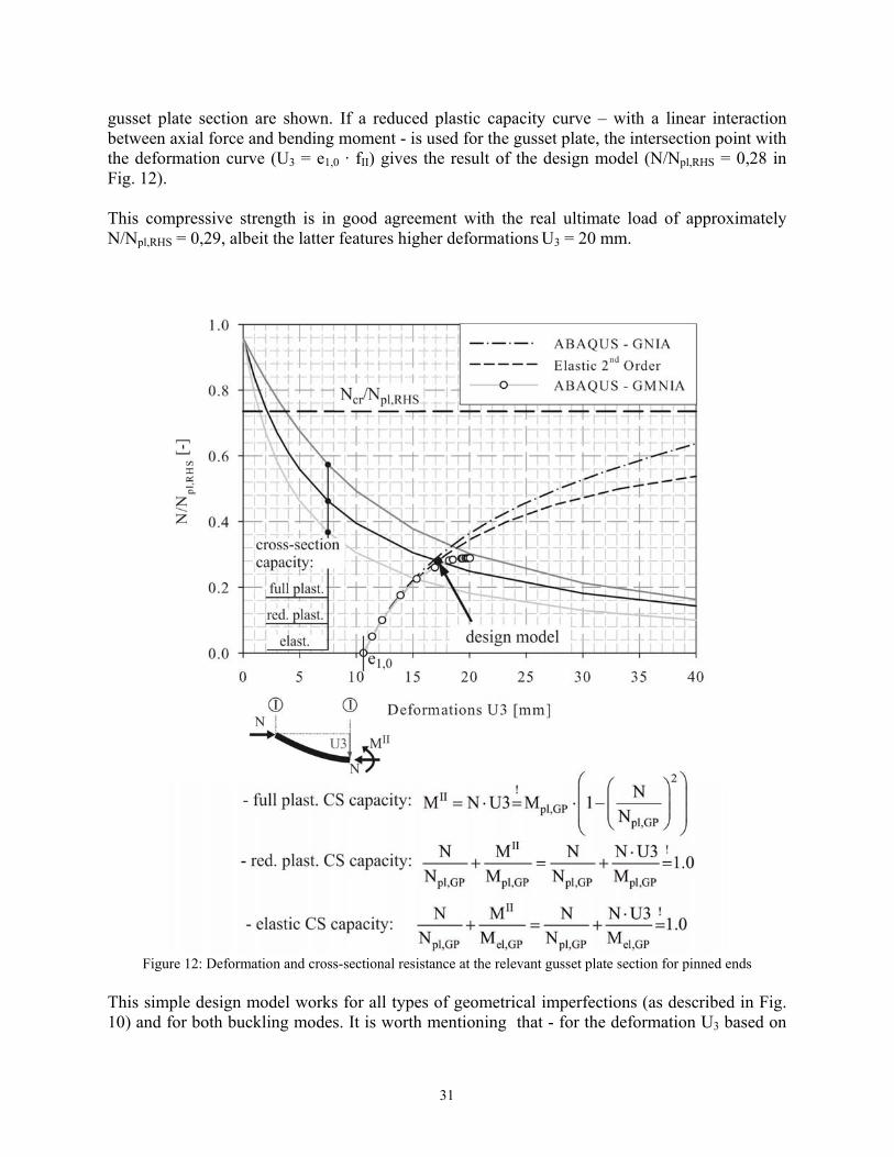
gusset plate section are shown. If a reduced plastic capacity curve – with a linear interaction between axial force and bending moment - is used for the gusset plate, the intersection point with the deformation curve (U3 = e1,0 · fII) gives the result of the design model (N/Npl,RHS = 0,28 in Fig. 12). This compressive strength is in good agreement with the real ultimate load of approximately N/Npl,RHS = 0,29, albeit the latter features higher deformations U3 = 20 mm.
Figure 12: Deformation and cross-sectional resistance at the relevant gusset plate section for pinned ends
This simple design model works for all types of geometrical imperfections (as described in Fig. 10) and for both buckling modes. It is worth mentioning that - for the deformation U3 based on
31

the simple elastic 2nd order amplification factor, the relevant ideal buckling load Ncr,i must always be considered. Table 1 summarized some additional examples. The results of the simple engineering design model (NEng.model) are compared with the FEM-calculations (NGMNIA). It can be seen that - for the eigenmode-affine imperfections, with equal amplitudes, see Fig. 10a- nearly in all cases the 2nd modes lead to the lower ultimate compressive strength. In the case of a member with clamped ends at the gusset plate (BC2 in Fig. 3), the design model is more complex due to the fact that the overall moment Mges caused by the deformation w1 at the member end must be splitted in two individual parts for the two relevant sections I and 1, see Fig. 13. Table 1: Load bearing capacities NR [kN] for the variation of geometric imperfection shapes only (based on Fig. 10);
RHS 100/200/10, t1 = 28, L1 = 400 mm
end support
length L0 [m]
Ncr,1 Ncr,2
eigenmode-affine; e0,max = L0/750 Gusset plate inclination e1,0
[mm] NGMNIA
[kN] NEng.model
[kN] e1,0
[mm] NGMNIA
[kN] NEng.model
[kN] BC 1 pinned
4,0 1.184 1527
4,51 5,33
670 707
680 (+1,5 %) 708 (+0,1 %)
4,0 4,0
697 772
707 (+1,4 %) 786 (+1,8 %)
8,0 954 1.313
4,45 10,6
611 514
615 (+0,7 %) 497 (-3,3 %)
4,0 4,0
646 726
633 (-2,0 %) 740 (+1,9 %)
12,0 595 1.213
2,78 14,6
497 430
497 (0 %) 412 (-4,2 %)
4,0 4,0
521 700
467 (-10,4 %) 1
716 (+2,3 %) BC 2 fully clamped
4,0 4.642 5.199
3,27 5,32
1.386 1.241
1.361 (-1,8 %) 1.217 (-2,0 %)
4,0 4,0
1.373 1.340
1.300 (-5,3 %) 1.313 (-2,0 %)
8,0 1.791 4.697
1,13 8,65
1.213 1.086
1.357 (+12 %) 1.012 (-6,8 %)
4,0 4,0
1.312 1.351
1.064 (-19 %) 1
1.302 (-3,6 %) 1. not relevant, because buckling of the member determined (section m)
The proposed design model for this cases focuses now on section I, because at this location a design verification of the welded connection is needed as well. The moment in section I can conservatively be estimated to amount to about 70 % of Mges, due to the fact that the simple engineering model underestimates the deformation w1 by using fII. In partial compensation of this error, it can be shown that at section I the full plastic section capacity can be utilized.
32

5.2 Sumslotted gSummincompres This de(particuagainst represenThe verAlternat(utilizatof the m Veri Con
buck For
incre Note
Veria) geom
e1,0 =
Figure 13: E
mmary of thegusset plateng up the ssion streng
sign model ularly, buck
axial comprntation of thrification otively, for tion factor e
member.
ification 1: bnventional bkling mode the calcula
eased lengthe: Verificat
internal f
ification 2: ametric impe= L1/100 ≥ 2
Engineering m
e suggested es
results of gth of memb
can be adaling curvesression forc
he design moof the mem
each verifequal to 1,0)
buckling chbuckling ch(L = 1 · L0
ation of theh L1
* = L1 +tion 1 checkforces (comp
additional verfection at t2 mm
model for the ca
design mod
section 4 bers with slo
apted to difs and toleraces Nd. For aodel all safe
mber contaification a m) – the mini
heck of the meck, based
0, see Fig. 5)e effective + h/5 shouldks the mempression + b
verification othe gusset p
alculation of th
del for the co
and 5.1, a otted gusset
fferent natioance requirea better undety factors ains two indmaximum imum of bo
member on an incr
) length fact
d be used mber in the bending) ex
of the sectioplate (section
he load bearin
ompression
design moplates is no
onal codes, ements) forderstandingare omitted.dividual chcompressio
oth gives the
reased effec
tor 1 using
region neaxceeding the
on capacity n 1)
ng capacity Nd
strength of
odel for thow available
which mayr column bof the prop
hecks - boton strength e resulting c
ctive buckli
g e.g. the g
ar midspan e section cap
of the gusse
d for fixed end
f members w
he calculatioe.
y have diffebuckling verosal, in the
th must becan be d
compression
ing length f
graphs in F
against secpacity
et plate
ds
with
on of the
erent rules rifications following
fulfilled. determined n capacity
for the 1st
Fig. 5, an
cond-order
33

Note: Based on execution codes EN 1090-2 (2008) and EN ISO 13920 (1996). Different imperfection amplitudes may be considered on the basis of other national or industry-specific tolerance requirements.
b) geometric equivalent imperfections at the gusset plate (section 1) e1,equ = fequ · e1,0 = 2.0 · e10 = 2.0 · L1/100 ≥ 4 mm Note: The factor fequ is a very conservative assumption, based on the study of the effects of
residual stresses due to welding of the connection between gusset plate and member.
c) verification pinned ends (BC1): (only reduced plastic section capacity available)
∙ , ∙,⁄ , , ∙ 1 , ,⁄ (5)
fully clamped ends (BC2):
0,7 ∙ ∙ , ∙,⁄ , , ∙ 1 , ,⁄ (6)
- End moment MI (basis for weld connection design)
0,7 ∙ ∙ , ∙,⁄ (7)
Note 1: - the ideal buckling load Ncr,1 for the 1st mode must always be used Note 2: - the plastic section capacity M1,pl,Rd and N1,pl,Rd of the gusset plate are defined (with
Fyd … design value of the yield stress), respectively:
, ,∙∙ ; , , ∙ ∙
References Zhao, R., Huang, R., Khoo, H.A., Cheng, J.J.R. (2009). “Parametric finite element study on slotted rectangular and
square HSS tension connections”. Journal of constructional steel research, 65 611-621. Unterweger, H. (2010). “Load bearing capacity of bracing members with almost centric joints”. Proceedings of Int.
conference stability and ductility of steel structures – SDSS, Rio de Janeiro, 603-610. Unterweger, H., Taras, A. (2011). “Hohlprofile mit beidseits zentrisch eingeschlitzten Knotenblechen –
Drucktragverhalten und Bemessungsvorschlag.” Stahlbau, Band 680, Heft 11, 839-851. Eurocode EN 1993-1-1 (2012). “Eurocode 3; Design of Steel Structures – Part 1-1: General rules and rules for
buildings.” Eurocode EN 1090-2 (2008). “Execution of steel structures and aluminium structures – Part 2: Technical
requirements for steel structures.” EN ISO 13920 (1996). “Welding – General tolerances for welded constructions – Dimensions for lengths and
angles, shape and position.” Petersen, Ch. (1982). “Statik und Stabilität der Baukonstruktionen”. Vieweg & Sohn, 2. Auflage. Pflüger, A. (1964). “Stabilitätsprobleme der Elastostatik”, Springer Verlag, 2. Auflage. Dimitrov, N. (1953). “Ermittlung konstanter Ersatz-Trägheitsmomente für Druckstäbe mit veränderlichen
Querschnitten”. Der Bauingenieur, 28, H6, 208-211.
34