columns (compression members)
TRANSCRIPT

1
Columns (Compression members):Columns are element with height larger or equal three times the least dimension; primary designed for compressive loads, and classified to short and Long (slender) columns.
Types of columns:1- Tied columns: with separate ties at distance as allowable.
2- Spirally reinforced columns: effect of spiral indicated in figure.
3- Composite columns

2
Limits for reinforcement of compression members ( ACI-CODE 08):
1- Area of longitudinal reinforcement: For compression members shall be not less than 0.01Ag or more than 0.08Ag. Minimum number of longitudinal bars in compression members shall be 4 for bars within rectangular or circular ties, 3 for bars within triangular ties, and 6 for bars enclosed by spirals.
2- Tie reinforcement for compression members shall conform to the following:3.1- Tie reinforcement for compression members shall conform to the following:
All bars shall be enclosed by lateral ties, at least No. 10 in size for longitudinal bars No. 32 or smaller and at least No. 13 in size for No. 36, No. 43, No. 57, and bundled longitudinal bars. 3.2- Vertical spacing of ties shall not exceed 16 longitudinal bar diameters, 48 tie bar or wire diameters, or least dimension of the compression member. Ties shall be arranged such that every corner and alternate longitudinal bar shall have lateral support provided by the corner of a tie with an included angle of not more than 135 degrees and no bar shall be farther than 150 mm clear on each side along the tie from such a laterally supported bar. Where longitudinal bars are located around the perimeter of a circle, a complete circular tie shall be permitted.
3.3- Ties shall be located vertically not more than one-half a tie spacing above the top of footing or slab in any story, and shall be spaced as provided herein to not more than one-half a tie spacing below the lowest horizontal reinforcement in slab, drop panel, or shear cap above.
3- Spirals: Spirals shall consist of evenly spaced continuous bar or wire of such size and so assembled to permit handling and placing without distortion from designed dimensions. For cast-in-place construction, size of spirals shall not be less than 10 mm diameter.
Clear spacing between spirals shall not exceed 75 mm, nor be less than 25 mm. Volumetric spiral reinforcement ratio, ��� , shall be not less than the value given by

3
��� = 0.45 � �� � 22 � 1� ���
��� Or ��� = 0.45 � ���� �2
2 � 1� ������
And the spacing ������ = 4��� (��� � ���� )��� ���� � 2
Anchorage of spiral reinforcement shall be provided by 1-1/2 extra turns of spiral bar or wire at each end of a spiral unit. Spiral reinforcement shall be spliced, if needed, by any one of the following methods:(a) Lap splices not less than the larger of 300 mm and the length indicatedbelow:(1) deformed uncoated bar or wire............... 48d(2) plain uncoated bar or wire ...................... 72d(3) epoxy-coated deformed bar or wire........ 72d
��������� ������ :for compression members shall not be taken greater than �������� computed by ;
1- For nonprestressed members with spiral reinforcement ;
�! = "��, #�$ = 0.85 � "[0.85 �� � � ( � ��) + �� � ��]2- For nonprestressed members with tie reinforcement;
�! = "��, #�$ = 0.8 � "[0.85 �� � � ( � ��) + �� � ��]

4
Compression-controlled sections, as defined above the " value:(a) Members with spiral reinforcement .................................0.75(b) Other reinforced members ............................0.65For sections in which the net tensile strain in the extreme tension steel at nomi������������ t, isbetween the limits for compression-controlled and tension-���������� ��������� � shall be permitted to be linearly increased from that for compression-����������������������������� tincreases from the compression controlled strain limit to 0.005.
��������-factor is used for compression-controlled sections than is used for tension-controlled sections because compression-controlled sections have less ductility, are more sensitive to variations in concrete strength, and generally occur in members that support larger loaded areas than members with tension-controlled sections. Members with spiral reinforcement are assigned �������� than tied columns because they have greater ductility or toughness.
Ex.1: For the two columns shown below compare the capacity of the columns if they specify the minimum ACI-Code requirements. (f’c=25MPa, and fy = 414MPa)
For tied: �! = 0.8 � "[0.85 �� � � ( � ��) + �� � ��]�! = 0.8 � 0.65 %0.85 � 25(450 � 450 � 4�&�202
4 ) + 4�&�2024 � 414'/1000= 2494.37 kN
For spiral:
�! = 0.85 � 0.75 %0.85 � 25(&�45024 � 6�&�202
4 ) + 6�&�2024 � 414'= 2627.36kN
The ratio = 2627.36/2494.37 = 1.05
Ex.2: Design a short tied column support service dead load of 1600kN and service live load of 900kN try �� � *��- ���#��� = 28## ��� � �� 1.7% with f’c= 20.7MPa and fy = 350MPa.
Pu= 1.2 *1600 + 1.6* 900 = 3360 kN� = ��
then Ast = 0.017 Ag
�! = 0.8 � "[0.85 �� � � ( � ��) + �� � ��]3360 � 1000 = 0.8 � 0.65[0.85 � 20.7( � 0.017 � ) + 0.017 � 350]

5
Ag= 277963.45mm2 the - = 9277963.45 = 527.2## use 530mm
3360 � 1000 = 0.8 � 0.65[0.85 � 20.7(5302 � ��) + �� � 350]Ast= 4570.036mm2 no. of bars = 4570.036
&�142 = 7.4 use 8 bars
���� = 8 � & � 142530 � 530 = 0.0175 �;. > 1% ��� < 8%
For ties use 10mm bars with spacing � ? 16 � 28 = 448## ? 48 � 10 = 480## ? 530##Use 10 mm ties @ 440mm c/c
Clear spacing for
Sect. A= 530�2�40�2�10�4�283 = 106## < 150## �� ���� �� ���������@ ���
Sect. B= 530�2�40�2�10�3�282 = 177## > 150## ���� �� ���������@ ���.
Ex.3: Design a short circular spirally reinforced column support service dead load of 1100kN and service live load of 950kN try �� � *��- ���#��� = 25## ��� � �� 2% with f’c= 27.5 MPa and fy = 400MPa.
Pu= 1.2*1100+ 1.6* 950 = 2840 kN� = ��
then Ast = 0.02 Ag
�! = 0.8 � "[0.85 �� � � ( � ��) + �� � ��]2840 � 1000 = 0.8 � 0.65[0.85 � 27.5( � 0.02 � ) + 0.02 � 400]Ag= 176705.93 mm2 the � = A4�176705 .93
& = 474.3## use 480 mm

6
2840 � 1000 = 0.8 � 0.65 B0.85 � 27.5(& � 48024 � ��) + �� � 400C
Ast = 3270.36 mm2 try bars with 30 mm diameter, then no. of bars = 3270.36&�152 = 4.6 bars use
minimum of 6 bars
���� = 6 � & � 152& � 48024
= 0.0234 �;. > 1% ��� < 8%For spirals use bars with 10mm diameter then:
��� = D. EF � GHGIJKLMM � N� O�I
OPQ = D. EF R ESDM(ESD�M�ED)M � NT MU.F
EDD = D. DNVW������ = 4 � ��(��� � � ��� )��� � ��� � 2 = 4 � 79(400 � 10)0.0136 � 4002
= 56.6 ## !�� 50## > 25 ��� < 75## �. ;.
Ex.4: Design a rectangular short tied column with h/b ratio of 1.5 , support service dead load of 300kN and service live load of 500kN try �� � *��- ���#��� = 20## ��� � �� 2% with f’c= 20.7MPa and fy = 400MPa.
Pu= 1.2 *300 + 1.6* 500 = 1160 kN� = ��
then Ast = 0.02 Ag
�! = 0.8 � "[0.85 �� � � ( � ��) + �� � ��]1160 � 1000 = 0.8 � 0.65[0.85 � 20.7( � 0.02 � ) + 0.02 � 400]Ag= 88371.526mm2 = - � � = 1.5�2 �-�� � = A88371 .526
1.5 = 242.7## use 250mm
h= 1.5*250=375mm use 380mm Ag = 250*380mm2
1160 � 1000 = 0.8 � 0.65[0.85 � 20.7(250 � 380 � ��) + �� � 400]Ast = 1807.52mm2 no. of bars = 1807.52
&�102 = 5.7 use 6 bars

7
���� = 6 � & � 102250 � 380 = 0.0198 �;. > 1% ��� < 8%
For ties use 10mm bars with spacing � ? 16 � 20 = 320## ? 48 � 10 = 480## ? 250##Use 10 mm ties @ 250mm c/c
Clear spacing for = 380�2�40�2�10�3�202 = 110## <
150## �� ���� �� ���������@ ��� Plastic centroid: the point that the resultant of compressive loading should be applied through and it coincide with the section center if symmetry exist.
Po = Cc + Cs = 0.85*f’c*b*h+As*fy+As’ *fy
X = �� � $ = Y� � -2 + ���(- � �� ) + ������Where:Po= resultant of forcesCc= concrete compressive strengthCs= steel compressive strength.
Ex.5: Find the position of plastic centroid for the column section shown below, use f’c=30MPa and fy= 400MPa. (As total = 10 20mm )Po= [0.85*30(300*600+200*200)+10*314*400]/1000
Po= 6866kNCc*Xc= 0.85*30[300*600*350+200*200*100]/10 = 1708.5kN.m
6
As*fyx=400[2*314*40+4*314*240+4*314*460]/106
= 361.73 kN.m

8
M= Cc*Xc +As*fyx= 1708.5+361.73=2070.23kN.mPo*X= M then X= 2070.23/6866 = 0.302= 302mm
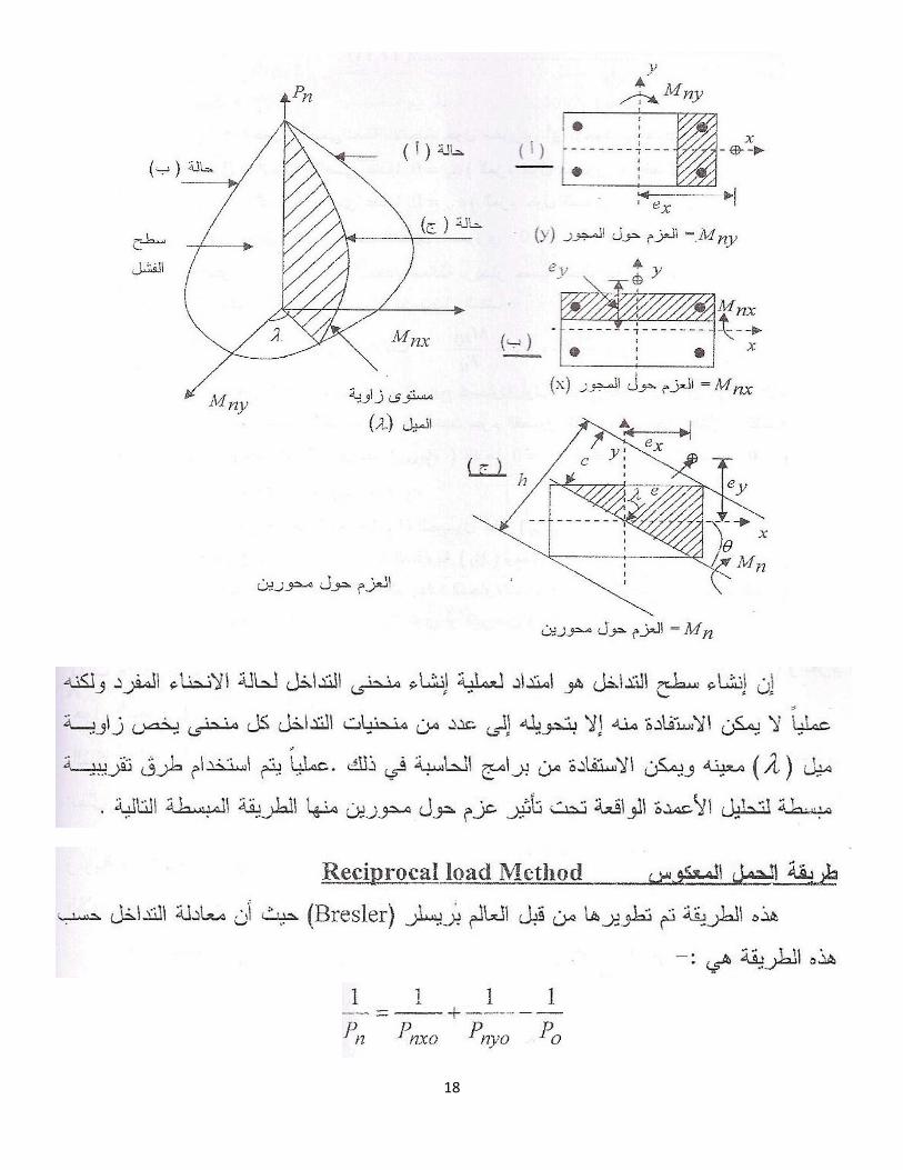
Analysis of rectangular eccentrically loaded columns:
:���������� !��"�#$"%&�'()Z� = ���
� Z! and Z� = ���� Z! then �� = 600 ���
� and ��� = 600 �����
:(*+,-"�./01-"�2%3�4). -"�56�7)�8%9-"�*:"%&�'()\ �� = 0 �� = Y� + Y� � ^ then �� = 0.85�� �. �. � + �� . ��� + �. ��

9
_ X = 0 ��. � = Y� �-2 � �2� + Y� �-2 � �� � + ^(� � -2)X = 0.85�� �. �. � �-2 � �2� + �� . ��� (-2 � �� ) + �. ��(� � -2)Ex.1; A short column 300*500mm supports load with eccentricity of e= 150 mm find nominal section axial capacity and moment, use d’ =60mm, f’c= 25MPa and fy= 350MPa?
Assume c=300mm then a= 0.85*300=255mm
Fs=600(d-c)/c= 600(500-60-300)/300= 280MPa
T =280 *1323 /1000 = 345kN
Fs’= 600 (c-d’)/c= 600 (300-60)/300= 480 MPa > 350MPa
Cs’ = 350*1232 /1000 = 431.2kN
Cc = 0.85*25*255*300/1000 =1625.63kN
Pn= Cc+Cs’ –T = 1625.63431.2-345= 1711.83kN
_ X = 0 ��. � = Y� �-2 � �2� + Y� �-2 � �� � + ^ �� � -2�X� = 1625.63(0.25 � 0.128) + 431.2(0.25 � 0.06) + 345(0.44 � 0.25) = 345.8;`. #E= 345.8/1711.83= 0.2m = 200mm more than 150 mm
Try c= 350mm then a= 298mm
Fs=600(d-c)/c= 600(500-60-350)/350= 154MPa
T =154 *1323 /1000 = 189.73kN
Fs’= 600 (c-d’)/c= 600 (350-60)/350= 350 MPa
Cs’ = 350*1232 /1000 = 431.2kN
Cc = 0.85*25*298*300/1000 =1899.75kN
Pn= Cc+Cs’ –T = 2141.22kN
_ X = 0 ��. � = Y� �-2 � �2� + Y� �-2 � �� � + ^ �� � -2�

10
X� = 1899.75(0.25 � 0.15) + 431.2(0.25 � 0.06) + 189.73(0.44 � 0.25) = 307.95;`. #e= 307.95/2414.22= 0.144m = 144mm less more than 150 mm try another value of c.
)�;<./0(=-"�;1>?�@,A�B-C�+1� <)����3�D=E�@-"�FG!-"�FHI�@,A�"J�1�A"�K+1A�"�L�M&e����N-") (-:OP�;>-��-"
1- Balanced Failure ��������������:The failure happened when the stresses in steel reach the value of maximum (fy) at the same moment the strain in concrete reaches the maximum value of (Z! = 0.003)
�� = 0.003��0.003+Z� = 600��
600+�� then ��� = 600 ����� ? ��
Y� = 0.85�� �. �. � ��� � = a � � ��� = 0.85�� �. �. � + �� . ��� + �. �� X�� = 0.85�� �. �. � �-
2 � �2� + �� . ��� (-
2 � �� ) + �. ��(� � -2)
�� = X��/���2- Tension failure ���������
3- Compression failure��� !"#$�����
Q,�1-"�4. -")�F1N-"�@,A�"J�1�A"�; ?%�1-"�FG!-"�2�HI"�'>R<)�K+1A=-�4). -�7�8%9-"�;?=A�ST%<�U��J"�FHG-"�*"

11
:;>-��-"���J� 1-"�V�3

12
Ex. 2: Find the balanced eccentricity for the column shown use f’c= 30MPa and Fy= 400MPa?
AS= As’ = 1847mm2Cb
a=600d /(600+fy) =600*440/(600+ 400) = 264mm
b
f’s =600*(264 -60)/264 = 463 > 400MPa T =Cs’= 400 *1847/1000 = 738.8kNCc = 0.85*30*224.4*300 /1000 = 1716.7kNPnRbR = Cc + Cs’-T = Cc = 1716.7kN MnRbR = 1716(0.25-0.112) + 738.8(0.25-0.06) +738.8(0.44-0.25)= 517.65 kN.meRbR =517.65/1716.7 = 0.302m = 302 mm

13
Ex.3: The column shown in figure below finds the axial strength and moment capacity, use f’c=30MPa, fy= 400MPa and 4 bars with 28mm diameter if:
=0.85*264= 224.4mm1- ex= 250mm2- ey= 250mm
For c = 0.7 �-�� d� = 0.36For c = 0.8 �-�� d� = 0.38Then for c = 0.76 �-�� d� = 0.37

14

15
Ex.4: A short tied column with 400x550mm supports Pu=4000kN and Mu= 220kN.m .find area of steel required if f’c =30MPa and fy= 400MPa and d’= 70mm use two layer one at each side.
d� = 4000 � 10000.65 � 30 � 400 � 550 = 0.93For c = 0.7 �-�� � = 0.023For c = 0.8 �-�� � = 0.021Then for c = 0.75 �-�� � = 0.022

16
Ex.5: Design the rectangular column if it supports Pu= 2200kN and Mu= 660kN.m, using f’c= 30MPa and fy= 400MPa( assume � = 0.03 �� � ��� � ��).Try h= 600mm and d’= 75mm
then c = 600�2���600 = 0.75 � = X!
�! = 300## �-�� �- = 0.5
For c = 0.7 �-�� d� = 0.46For c = 0.8 �-�� d� = 0.50Then for c = 0.75 �-�� d� = 0.48
d� = ���� � � � � - = 2200 � 10000.65 � 30 � � � 600 = 0.48 e � = 392## !�� � = 400##As= 0.03 * 400* 600= 7200mm2Use 8 36mm (4 at eacg side) anduse 12mm for tiesSpacing W�XYZ[\�]�^_`aa W�X`�Zb`�]^_`aa W�[��aa���
Ex. 6: A circular column with diameter of 400mm supports design load of 2800kN and designmoment of 135kN.m. Find area of steel and stirrups required for the section, use f’c= 30MPa, d’= 60mm and fy= 400MPa.
� = X!�! = 1352800 = 0.048# = 48## �-�� �� = 48400 = 0.12 = & � 4002
4 = 125664 ##2Try = 0.75 then
and c = 400�2�60400 = 0.7
from the chart � = 0.045 �-�� �� = 0.045 � 125664 = 5655##2Use 8 30mm for stirrups use 10mm dcore= 400 - 2*40= 320mm

17
��� = 0.45 R ���� � 22 � 1T ������ = 0.45 f 4002
(320)2 � 1g 30400 = 0.016
������ = 4 � ��(��� � � ��� )��� � ��� � 2 = 4 � 79(320 � 10)0.016 � 3202 = 59.8 ## !�� 50## > 25 ��� < 75## �. ;
18

19

20
Ex.7: Check the adequency of the column shown below the loads Pu= 1200kN and the moments are Mux= 90kN.m and Muy= 180kN.m, use f’c= 30MPa and fy= 400MPa.Try = 0.65
Moment about y-axis :�$ = X!��! = 1801200 = 0.15# = 150## �-�� �- = 0.3
Moment about x-axis :�� = X!$�! = 901200 = 0.075# = 75## �-�� �- = 0.25then c = 180�2�60
180 = 0.6 from charts Kn = 0.67= ��f’c �b�h
Pn= Pnx0= 0.67* 30* 300 *500 /1000 = 3015kN
For ex=0 and ey=0 Pno =[ 0.85*30(300*500-4928) +400*4928]/1000= 5670.54 kN1
�� = 12790 + 1
3015 � 15670.54 then Pn = 1946.5kN
Pu= 0.65*1946.5 = 1265.2 kN W��cd]���`^Z���\Z�5670.54 =2948.7 kN o.k.
Pu W� Pn o.k.
Ex.8: A rectangular tied column with 400*500mm reinforced with 6 bars 0f 30mm diameter arranged as shown below, calculate the loads ( Pu) that is appliedat the corner of the column, use f’c= 30MPa, and fy= 400MPa.
Moment about x-axis: e=200mm

21
e/h= 200/400=0.5
then c = 400�2�60400 = 0.7 � = 6�&�302
400�500�4 = 0.0212from charts Kn = 0.42= ��
f’c �b�hPn= Pnx0= 0.42* 30* 400 *500 /1000 = 2520 kN
Moment about y-axis: e=250mm then e/h= 250/500=0.5 and c = 500�2�75500 = 0.7
� = 4�&�302400�500�4 = 0.01414 from charts Kn = 0.36= ��
f’c �b�hPn = Pnx0= 0.36* 30* 400 *500 /1000 = 2160 kN
Pno =[ 0.85*30(400*500-6*707) +400*6*707]/1000= 6688.63kN1
�� = 12520 + 1
2160 � 16688.63 then Pn = 1408.2kN
Pu= 0.65*1408.2 = 915.33kN W� Pu= 0.65* 0.8* 6688.63 =3478.08 kN o.k.
Ex.8: The circular spiral column with diameter of 500mm is reinforced by 8 bars of 25mm the axial aplied load was Pu =2250kN , what moment would cause the column fail? Use f’c= 30MPa, and fy= 400MPa.
c = 500�2�75500 = 0.7
Kn = ��"f’c�Ag = 2250�1000
0.75�30�&�5002/4 = 0.507 � = 8 � & � 252/4& � 5002/4 = .02From chart e/h= 0.25 then e= 0.25*500=125mm
Mu= 2250* 0.125 = 281.25 kN.m
Ex.9 : The circular spiral column with diameter of 500mm is reinforced by 8 bars of 25mm the axial aplied load was Pu = 1200kN , the moments are Mux= 90kN.m and Muy= 180kN.m, use f’c= 30MPa, d’= 75mm and fy= 400MPa. Check the adequency of the column shown below.
c = 500�2�75500 = 0.7 �$ = X!�
�! = 1801200 = 0.15# = 150##

22
�-�� �- = 150
500 = 0.3�� = X!$�! = 901200 = 0.075# = 75## � ��!@���� = o1502 + 752 = 167.7## � = 8�&�252/4
&�5002/4 = .02from charts Kn = 0.41= ��
f’c �AgPn = 0.41* 30* e *5002
Where:
/(4*1000) = 2416.07 kN
Slender columns (long columns):A column is said to be slender if its cross-sectional dimension are small compared with its length (Height). Slender columns fail by buckling at the critical buckling ,compression Eular’s load (Pc):
�� = &2pq(;r! ))2 Or buckling compression stress
PcA = t2 EIA(kLu )2 = t2E
(kLur )2 K = A{
| = K}~��� JO HPK}Q�J� JO Q�L IKJ�� � �LIQ�J�,
Lu= unsupported length of column ( clear span between floors)k= effective length factor ( measured between points of zero moments);r!
= �@���� ���� ���� < 100From the figure below it seen that the buckling stress (or load) decreases rapidly with increasing slenderness ratio for short column the value of buckling loads exceeds the direct crushing strengthPn = 0.85 f f c Ac + Ast fy When ;r!
< �;r! �@�#���� [ failur occurs by simple crushing
regardless of concrete strength]

23
When ;r! > �;r!
�@�#���� [failure occurs by buckling]
Effectve Length Measuerment:Effective length measured between the points of zero moments or inflection points, it depends on two factors :a) Rrestrained against rotation .b) Restrained against horizontal displacements.
Non-sway side sway
First: horizontal restrained (braced against side sway)The structurs built with (steel bracing, shear walls around stairs or lifts etc), it depends on the end supports and its rotation. Fig. a) shows hinge-hinge ends free end rotaion k=1 ,Fig. b) fixed-fixed ends (full restrained case) k=0.5 and Fig. c) partailly restrained in structrue which depends of stiffness of columns ratio to stiffness of beams (degree of restrained)
� = ��EILc �columns��EILc �beamsattached �-�� 0.5 < ; < 1
Second : free restrained (side sway exist)There is horizontal movement in the ends of column assume that one end move and the other restrained. Fig. d) shows fixed free end then k = 2 , Fig. e) no rotation for both ends k=1 and Fig. f) partially restrained in structures �-�� 1 < ; < �
Note: From above Pc value for braced column is larger than Pc for unbraced column and depending on degree of restrained k value could be calculated from the chart below.

24
Slenderness effects:ACI-Code 318 allow to neglect slenderness effect and design as short column if :
a) Braced columns (non- sway)neglect slenderness if ���
� ? VE � NM �N�M ? ED

25
where : M1 (smaller) and M2 (larger)
b) Un-braced columns (sway)
end moments�N�M � �D. F the sign of �N�M is (+) for single curvature and (-) for double curvature.
� = D. V� �� ��!� � ��� ����!@� ��@!#�� ( *-� � - �� �-� �� #�@ ��#������ �� ������) � = D. MF� �� �� �!@� ��@!#�� ( D is the diamerter)
neglect slenderness if ���� ? MM
Neglect side sway:ACI-Code 318 allow to neglect side sway effect if there are walls or any bracing as well as to:
1- Increase in moments due to sway case less than 5% from moment in linear calculation.2- Neglect side sway if the stability index (Q) less or equal (0.05):
� = �Pu �oVu Lc ? 0.05
Where:�Pu = sum of axial load in the floor (kN).Vu= sum of shear force in floor (kN).�o = horizontal displacement ( difference between displacement at the ends due to horizontal loads) (m)Lc = length of column center to center between floors (m).
ACI-Code Slenderness effects:ACI code for magnify the moments for long (slender) columns depends on increasing the
moments by multyplying the moment by factor larger than one. This increase came from axial
load multyplied by displacement due to rotation . The amount of increase depends on
direction and magnitude of main moments at the ends, if the structure is braced or
unbraced to side sway and the slenderness ratio. For single curvature shows increase in
moment at mid-span if the end moments are equal. For double curvature case the moments have
same sign, the moments become larger near the ends.

26
Moment magnification for Braced framesSlender columns shall be designed using the factored axial load obtained from conventional frame analysis and magnified moment defined for non-sway framesX� = �� X2Where: X2 = value of larger factored end moments. (M2 min = Pu (15+0.03h) in N.mm) �� = moment magnification factor �� = Y#
1� �!0.75�� � 1
Pu= design axial load from analysis (kN)
Pc = buckling load for column �� = &2pq(;r! ))2
Cm = factor curvature effect without transverse loads between supports
Secondary moment
Main moments
Increase in moment
due to single curvature
Increase in moment due to double curvature
Secooondary momemm nt
Main moments

27
Y# = 0.6 + 0.4 X1X2 � 0.4 (sign of ¡¢£¤¤¥� �N¤£�¦¥� �M is (+) for single curvature and (-) for double curvature) (for other cases Cm
=1.0) . To calculate Pc it is required:
1- Calculate k for the column � = ��EILc �columns��EILc �beams(for hing support=g���h � = 10 and for
fixed support =0 take � = 1)p� = 4700o�� � and Ig moment of interia of section without reinforcement.Beams Ib= 0.35Ig , Lc for beams are taken span cneter to center.Columns Ic= 0.7Ig , Lc for columns are taken span cneter to center.Walls no cracks Iw= 0.7Ig ,Walls with cracks Iw= 0.35Ig ,Slabs without beams Is= 0.25IgArea for beams, columns and slabs is taken Ag without reinforcements, Ig moment of interia for hall section. For (T) or (I) beams use Ig = 2Iweb
2- Find EI for columns in Pc equation pq = 0.4 p� q1+a� or more exact and if steel is known
and exist
.
EI = o. 2Ec Ig + Es. Ise1 + §dEs = 200000MPa for steel and Ise moment of interia of reinforcement about centroidal axis of
cross section.§d = ratio of maximum factored sustained axial dead load to maximum total factored axial load ( effect of creep)
§d = �PuD.L.susPuDL + PuLLEx.1) A rectangular tied braced column is reinforced with 6-28mm bars as shown in figure below check the adeqancy of the column for the followning gravity loads . Service dead load= 900kN, service live loads = 800kN both are at eccentricity of 40mm. Service dead load moments=34kN.m, service live load moments =25kN.m, F’c =27.5MPa, fy = 400MPa, Lu =5m ,���� = ������# = 1.0 ? Sol:
Pu = 1.2 (900)+1.6 ( 800) = 1080+1280 =2360 kN
Mu = 1.2* 34+ 1.6* 25 + 2360*0.04 = 175.2 kN.mCheck slenderness ���� = ����� = 1.0 �� � ���� ��@!#�

28
k= 0.77 from chart , r= 0.3* h= 0.3* 500=150mm
kLur = 0.77�5000
150 = 25.7 < 10034 � 12 X1
X2 = 34 � 12(+1) = 22kLu
r = 25.7 > 22 the column is slender
single curvature opposite direction momentsY# = 0.6 + 0.4 X1X2 � 0.4Cm =0.6 + 0.4 (1) =1
§d = �Pu D .L.susPu DL +Pu LL = 1.4�9002360 = 1260
2360 = 0.534
pq = 0.4 p� q1 + a� = 0.4 � �350 � 500312 � � 4700927.5 (1 + 0.534) � 109
= 23431.26 ;`. #2q�� = 6 R & � ��� 4
64 + �2T = 6 R& � 28464 + & � 282
4 (186)2T = 6(0 + 21302561) = 127815370.4 ##4
EI = o.2Ec Ig+Es .Ise1+§d = 0.2�350�500 3
12 �4700�927.5�+200000 �127815370 .4(1+0.534)�109 = 28379.95 kN.m2
�� = &2pq(;r! ))2 = ª2�28379.95
(0.77�5)2 = 18896.87 ;` �� = «¬
N� �D.UFI = N
N� MVWDD.UF�18896 .87= 1.199 � 1
Mmin = Pu*emin
Mc= �� � X2 = 1.199 � 175.2 = 210.06 ;`. #= 2360*(15+0.03*500)/1000= 70.8 kN.m
Design values:Pu=2360kN , Mc =213.64 kN.m
� = 210.06 � 10002360 = 89##�- = 89
500 = 0.178 > 0.1 �. ;

29
c = 500�2(40+10+282 )500 = 0.75
;� = �!"�� ��- = 2360 � 10000.65 � 27.5 � 350 � 500 = 0.754 For c = 0.7 � = 0.018 c = 0.8 � =0.017c = 0.75 � =0.0175As = 0.0175*350*500 = 3062.5 mm2 As provided 6-28 As= 3694mm2 more than required. The column is adequate.Ties -10mm spaecing ? 16*28= 448mm ?48*10= 480mm ?350mm then adequate.
Ex.2: The column with (300*375mm) and single curvature about y-axis shown below in a building braced against side sway,and ultimate loads shwon in figure (the service dead load of 133kN). Find steel area required and check the slenderness about bending axis (y-axis) use Lu=4.8m and k=0.85 f’c = 30 MPa fy = 400MPa,
Try as short column:
c = 375�2(60)375 = 0.68 use c = 0.7 then
;� = �!"�� ��- = 490 � 10000.65 � 30 � 300 � 375 = 0.223 ®� = X!"�� ��-2 = 117 � 10000000.65 � 30 � 300 � 3752 = 0.142 Then from charts find � = 0.013 which is less than maximum percent

30
Check slenderness:
kLur = 0.85�4800
0.3�375 = 35.4 < 10034 � 12 X1
X2 = 34 � 12 �115117� = 22.5 < 35.4 then column is slender
single curvature opposite direction momentsY# = 0.6 + 0.4 X1X2 = 0.6 + 0.4 112117 0.893 � 0.4§d = �PuD.L.susPuDL + PuLL = 1.4 � 133490 = 0.38
pq = 0.4 p� q1 + a� = 0.4 � �300 � 375312 � � 4700930 (1 + 0.38) � 109 = 9837.2 ;`. #2
�� = &2pq(;r! ))2 = ª2�9837.2
(0.83�4.8)2 = 5832 ;` �� = Y#
1 � �!0.75�� = 0.983
1 � 4900.75 � 5832= 1.107 � 1
Mmin = Pu*emin = 490*(15+0.03*370)/1000= 12.86 kN.mMc= �� � X2 = 1.107 � 117 = 128.7 ;`. #Design values:Pu = 490kN , Mc = 128.7 kN.m
®� = X!"�� ��-2 = 128.7 � 10000000.65 � 30 � 300 � 3752 = 0.16 For c = 0.7 � = 0.015 As = 0.015* 300* 375= 1688 mm2 As provided 6-20 As= 1886mm2 more than required. Ties -10mm spacing ? 16*20= 320mm ?48*10= 480mm ?300mm then adequate. Use 10mm @300mm c/c
31
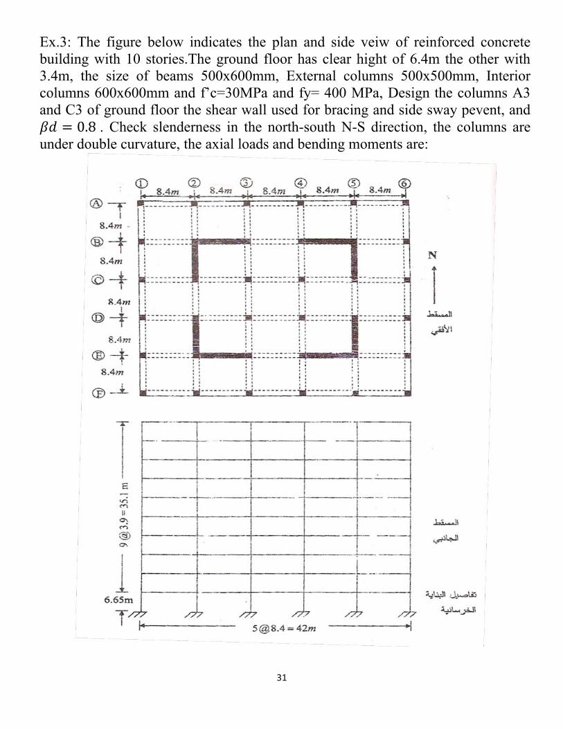
Ex.3: The figure below indicates the plan and side veiw of reinforced concrete building with 10 stories.The ground floor has clear hight of 6.4m the other with 3.4m, the size of beams 500x600mm, External columns 500x500mm, Interior columns 600x600mm and f’c=30MPa and fy= 400 MPa, Design the columns A3 and C3 of ground floor the shear wall used for bracing and side sway pevent, and a� = 0.8 . Check slenderness in the north-south N-S direction, the columns are under double curvature, the axial loads and bending moments are:

32
For column C3 try d’= 75mm
c = 600�2(75)600 = 0.75
;� = �!"�� ��- = 8950 � 10000.65 � 30 � 6002 = 1.28 ®� = X!"�� ��-2 = 16 � 10000000.65 � 30 � 6003 = 0.003
Then from charts find � = 0.052 Check slenderness use k=1:
kLur = 1�6400
0.3�600 = 35.6 < 10034 � 12 X1
X2 = 34 � 12 ��8.416 � = 40.3 > 40 !�� 40 *-��- > 35.6 �-�� �-� � ��@!#�
For column A3 try d’= 75mm
c = 500�2(75)500 = 0.7
;� = �!"�� ��- = 4870 � 10000.65 � 30 � 5002 = 1.0 ®� = X!"�� ��-2 = 158 � 10000000.65 � 30 � 5003 = 0.065
Then from charts find � = 0.028Check slenderness use k=1: kLu
r = 1�64000.3�500 = 42.7 < 100
34 � 12 X1X2 = 34 � 12 ��81
158 � = 40.14 > 40 !�� 40 *-��- < 42.7 �-�� �@���� ��@!#�

33
Check k exactly : � = ��EILc �columns��EILc �beams
q�r� �����# = 0.7 � 5004126650 = 0.548 � 106##4
q�r� ��� = 0.7 � 5004123900 = 0.935 � 106##4
q�r� = 0.35 � 600 � 5003128400 = 0.26 � 106##4
���� = ��EILc �columns��EILc �beams= 0.548�106+0.935�106
0.26�106 = 5.7������# = 1.0 ��$�� � �# �����#k = 0.84 and : kLu
r = 0.84�64000.3�500 = 35.9 <40
34 � 12 X1X2 = 34 � 12 � 81
158� = 27.85 < 35.9 �� ���@� �! ¯��! � �-�� �@���� ��@!#� Y# = 0.6 + 0.4 X1X2 = 0.6 + 0.4 81
138 = 0.8 � 0.4 ����i��]��\����
pq = 0.4 p� q1 + a� = 0.4 � �500412 � � 4700930 (1 + 0.8) � 109 = 29795 ;`. #2
�� = &2pq(;r! ))2 = ª2�29795
(0.84�6.4)2 = 10175 ;` �� = Y#
1 � �!0.75�� = 0.8
1 � 48700.75 � 10175= 2.21 � 1
M2 min= 4870(15+0.03*500)/1000=146.1 kN.m < M2=158kN.mMc= �� � X2 = 2.21 � 158 = 349.2 ;`. #Design values:c = 500�2(75)
500 = 0.7

34
;� = �!"�� ��- = 4870 � 10000.65 � 30 � 5002 = 1.0
®� = X!"�� ��-2 = 349.2 � 10000000.65 � 30 � 5003 = 0.14 For c = 0.7 � = 0.042 As = 0.042* 500*500= 10500 mm2 As provided 12 36 As = 12215 mm2 more than required. Ties -12mm spacing ? 16*36= 576mm ? 48*12= 576mm ? 500mm then adequate. Use 12mm @500mm c/c

35
Moment magnification for un-brasecd framesFor compression members (columns) not braced against sidesway effect of slenderness may be neglected when: kLu
r ? 22The moments M1 and M2 at the ends of an individual compression member shall be taken as:X1 = X1�� + � X1�
X2 = X2�� + � X2�Where: X1�� = factored end moments on a compression members at end at which X1 acts, due to loads that cause no appreciable side sway.X2�� = factored end moments on a compression members at end at which X2 acts, due to loads that cause no appreciable side sway.X1�= factored end moments on a compression members at end at which X1 acts, due to loads that cause appreciable side sway.X2�= factored end moments on a compression members at end at which X1 acts, due to loads that cause appreciable side sway. � = moment magnification factor for frames not braced against sidesway to reflect drift results from lateral (wind , earth pressure and gravity loads… etc.).
There are three methods to calculate moment magnification factor � X�:First- from nonlinear analysis of moments depending on moment of inertia :
Beams Ib= 0.35Ig , Lc for beams are taken span center to center. Columns Ic= 0.7Ig , Lc for columns are taken span center to center. Walls no cracks Iw= 0.7Ig , Walls with cracks Iw= 0.35Ig , Slabs without beams Is= 0.25Ig For (T) or (I) beams use Ig = 2Iweb .
Second: calculate from
� = 11�� � 1 and should be � ? 1.5 if not use the first or third method.
Third : the same � = 11� � �!0.75���
� 1(Note if � ? 2.5 the frame must be stiffened to reduce � and not exceed 2.5 ) ��! = sum of axil vertical factored loads for all columns in the floor under consideration. ��� = sum of all buckling loads for all columns in the floor under consideration.

36
�� = &2pq(;r! ))2 *-� � 1 ? ; < �
Find EI for columns in Pc equation pq = 0.4 p� q1+a� or more exact and if steel is known and
exist EI = o.2Ec Ig+Es .Ise1+§d
Es = 200000MPa for steel and Ise moment of interia of reinforcement about centroidal axis of cross section.
§d = ratio of maximum factored sustained lateral dead load to maximum total factored lateraload ( effect of creep)
§d = total sustained lateral (horizontal) loads in the floortotal lateral (horizontal) shear force in the floor for wind load and earthquake loads ±² = D because are generally at short duration butfor other cases like earth pressure ±² ³ D £´² ¡�µ¶¥·¸¥² ¹´ ¹´¥ ¡º²¥.If an individual compression member has: Lur > 35
A PuAg. fc�Then the maximum moments will be in a point between the column ends and not at the ends and the maximum moment will be larger than the magnified moment by 5% . then replay moment calculation as it is braced against side sway then magnify M1 and M2 as:
X1 = X1�� + � X1�X2 = X2�� + � X2�Thus the moments will be magnify two times first as non sway and second sway case with moments equal that gained from the first magnify as:Mc = ¼ns M2 = ¼ns ( M2ns + ¼sM2s )
The ultimate loads calulation with lateral should be calculated as:U = 1.2D + 1.6L
U =1.2D + 1.6L+ 0.8WU = 0.9D + 1.6W
U = 1.2D + 1.6L + 1.6H
Where; D= dead loads , L = live loads, W = wind loads, H = lateral soil pressure.

37
Ex. 4: The figure below indicates the side veiw of reinforced concrete building not braced against sidesway dimension of beams are (1200x300mm), interior columns (450x450mm), exterior columns 400x400mm clear height Lu= 3.9m, f’c= 30MPa , fy=400MPa, and horizontaldisplacement due to total shear wind loads (250 kN) at third floor = 20mm. Design the column C, the service loads and moments from linear analysis for third floor are :
loads Columns A3,F3 Columns B3, E3 Columns D3, C3Deadload Pd (kN) 500 1000 1000Live load PL 400(kN) 750 750Wind load Pw (kN) ½125 ½75 ½25Wind shear (kN) 25 50 50Dead load moment M2d (kN.m)
3
live load moment M2L (kN.m)
150
Wind load moment M2w (kN.m)
½115Dead load moment M1d (kN.m)
-3
live load moment M1L (kN.m)
135
Wind load moment M1w (kN.m)
½95

38
Vu= 1.6*250 =400kN�o= 1.6* 20 = 32mm
Pu = 1.2* 500 + 1.0 *400 = 1000kN for A3, F3 columns
Pu= 1.2* 1000+ 1.0* 750 = 1950kN for B3, C3, D3, E3 columns
_ �! = 2 � 1000 + 4 � 1950 = 9800;`� = \ �! ¾�¿! r� = 9800 � 32400 � 4200 = 0.19 > 0.05 !� � ���� � �#q�r� ��� =
0.7 � 4504124200 = 570 � 103##4q�r� =
0.35 � 1200 � 3003127200 = 263 � 103##4
���� = � �EILc �columns� �EILc �beams
= 2 � 5702 � 263 = 2.17 = ������#
k = 1.64 and : kLur = 1.64�3900
0.3�450 = 47.4 > 34 � 12 X1X2 = 34 � 12(1) = 22
For column C3 case of loading:
Load cases Design load (kN)
M2ns (due to gravity loads only) (kN.m)
M2s (due to wind loads) (kN.m)
Wu=1.2D + 1.6L 2400 243.6 0Wu=1.2D + 0.8W 1200 3.6 92Wu= 1.2D +1.6W +1.0L 1950 153.6 184Wu= 0.9D +1.6W 900 2.7 184

39

40

41
Ex.5: Design a typical exterior column (col.D4) of the third multi-stroy building . The stability index for this story Q= 0.36 f’c=27.5MPa and fy=400MPa. All columns are 500x500mm and height center to center of floor 5.8m, all the beams are 300*600mm.

42
Loading Exterior columns Interior columns NotesFactored axial load (kN)
2600 3500 for a� assume factored dead load is 50% of total factored loads
Factored non-sway moment Mns (kN.m)
M top= 100 Mbottom= 170
M top= 60Mbottom= 100
Factored sway moment Ms (kN.m)
M top= 70 Mbottom= 80
M top= 100Mbottom= 100
Assume all lateral loads are live loads a�=0
Sol; (� ¯�@!�� �$�� . ��@!#�)
(qr )��@!#� = 500�500 3
125800 = 900 � 103 ##3 , (qr )���# = 300�600 3
124500 = 1200 � 103 ##3
Àext. col. = Àtop = Àbottom = 0.7(900 + 900)0.35(1200) = 3since Q = 0.36 the story is not braced against sidesway k(ext.) unbraced=1.82
Àint. col. = Àtop = Àbottom = 0.7(900 + 900)0.35(1200 + 1200) = 1.5then k(int.) unbraced = 1.45
check slenderness col. D4
;@! = 1.82 � 52000.3 � 500 = 63 > 22 ��� < 100 �@���� ��@.pq = 0.4�4700�927.5(1+0)�109 � 500�5003
12 = 51348;`. #2All lateral loads are live load
for ext. columns Pcunbraced = t2�51348(1.82�5.2)2 = 5658 kN
for int. columns Pcunbraced = t2�51348(1.45�5.2)2 = 8914 kN
� = 11�� = 1
1�0.36 = 1.563 > 1.5 �� �$�. ��@. ��� �. ;.

43
� = 11� ��!0.75���
� 1.0 �� �� �� > 2.5 �-�� ��� ���� ������� ��#������ or increase number
of column or use shear wall.
��! = 16 � 2600 + 16 � 3500 = 97600 ;`��� = 16 � 5658 + 16 � 891 = 233152 ;` � = 1
1� 976000.75�(233152 )= 2.263 > 1.0 and < 2.5
M2=M2ns + � M2s = 170+2.263*80 = 351kN.m
M1= M1ns + � X1� = 100+ 2.263* 70 =258.4kN.m
r! = 5200
0.3�500 = 34.6735
A �!�� � � = 35
A 2600 � 10327.5 � 500 � 500= 56.91 > r! = 34.67 �-�� �� ���� �� X� = �� � X2
If r! > 35
A �!�� ��then take M2 new and magnified by �� as braced col. and use a� for axial load.
Design Pu =2600 kN M2 = 351kN.m � = 351�10002600 = 135##
�- = 135
500 = 0.27 K� = 2600�10000.65�27.5�500�500 = 0.58
assume using bars with 22mm and ties 10mm; c = 500�2(40+10+11)500 = 0.756
c = 0.7 �-�� � = 0.015c = 0.8 �-�� � = 0.012 c = 0.75 �-�� � = 0.0135 As = 0.0135*500*500 = 3375mm2
No. of bars = 3375&�(22)2
4= 8.88 !�� 10 �� �  22## As= 10*380 = 3800mm2
For ties use bars with 10mm

44
Spacing ? 16 � 22 = 352## ? 10 � 48 = 480## ? 500## then use 10mm @350mm c/c
Clear spacing in side the stirrups= 500�(2�40+5�22+2�10)4 = 72.5## < 150##
Use additional to provide for corner bars
Or the other order

45