mechanical governors and associated fuel injection...
TRANSCRIPT
MAJOR POWER MAJOR
)SUPPLEMENT SECTION 2
MECHANICAL GOVERNORS AND ASSOCIATED FUEL INJECTION PUMPS
On industrial diesel engines which require accurate and sensitive speed control a mechanical centrifugal type governor is fitted at the rear of a conventionally operated type of fuel injection pump.
Two basic types of mechanical governor may be encountered in service, the GV type on early engines and the GM type on current production engines. Both types may, however, be found with various speed ranges depending on the engine application.
The basic principles of operation of the fuel injection pump have been fully covered in previous tractor bulletins and existing repair manuals, therefore, using the pneumatic governed pump fitted to standard tractor diesel engines, as a basis for comparison, the differences which exist in build-up and design of individual components are detailed below.
The mounting of a mechanical governor on the rear of the injection pump necessitates the fitting of a slightly modified excess fuel and stop device at the front of the injection pump. It also means that a special pump control rod is fitted which operates in ,t$e opposite direction to that on the pneumatic gkerned pump. In consequence the helices on the pump plungers are machined in the opposite direction and the elements are not therefore interchangeable with those fitted to tractor pumps.
The pump body is a special one having a fuel inlet at the front, whereas when a pneumatic governor is fitted the fuel inlet is at the rear of the body. Likewise a different cambox is used on which provision has been made for mounting the fuel lift pump directly to the side of the casing.
The injection pump camshaft incorporates a thread and keyway at both ends, which means that care must be taken on assembly to ensure that it is fitted correctly. View the camshaft from one end and rotate it in a clockwise direction, observing the positioning of the cams. The end which shows the peaks of the cams coming to the vertically upward position in the order I, 2, 4, 3 must be assembled away from the governor end of the injection pump.
It should also be noted that where a GV governor is fitted, the camshaft front and rear bearing housings are identical with that used at the front of the
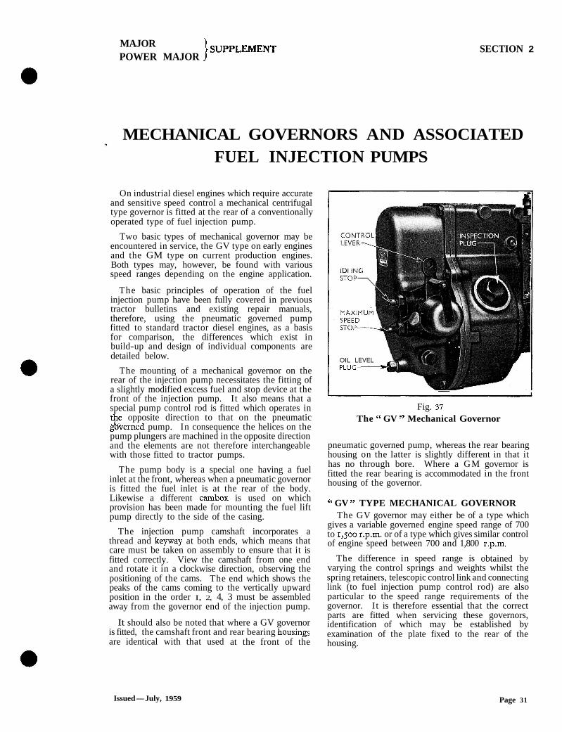
OIL LEVEL 1 PLUG-4
Fig. 37
The " GV " Mechanical Governor
pneumatic governed pump, whereas the rear bearing housing on the latter is slightly different in that it has no through bore. Where a GM governor is fitted the rear bearing is accommodated in the front housing of the governor.
" GV " TYPE MECHANICAL GOVERNOR The GV governor may either be of a type which
gives a variable governed engine speed range of 700 to 1,500 r.p.m. or of a type which gives similar control of engine speed between 700 and 1,800 r.p.m.
The difference in speed range is obtained by varying the control springs and weights whilst the spring retainers, telescopic control link and connecting link (to fuel injection pump control rod) are also particular to the speed range requirements of the governor. I t is therefore essential that the correct parts are fitted when servicing these governors, identification of which may be established by examination of the plate fixed to the rear of the housing.
Issued-July, 1959 Page 31

MAJOR POWER MAJOR 1 SUPPLEMENT SECTION 2
B ,- ROCKING LEVER
CROSS HEAD
\ l\.-;>- OPERATING LEVER
IRNED SPEED-REDUCED FUEL POSITION W Fig. 38
The " GV " Mechanical Governor-Diagrammatic View (Showing Maximum Speed and Idling Positions) Page 32
MAJOR POWER MAJOR
}SUPPLEMENT SECTION 2
The identification plate shows the type of governor and the speed range in pump r.p.m. (half engine speed)-GVA 3501750 indicates a governed engine speed range of 700 to 1,500 r.p.m. and GVA 35o/goo a governed range of 700 to 1,800 r.p.m.
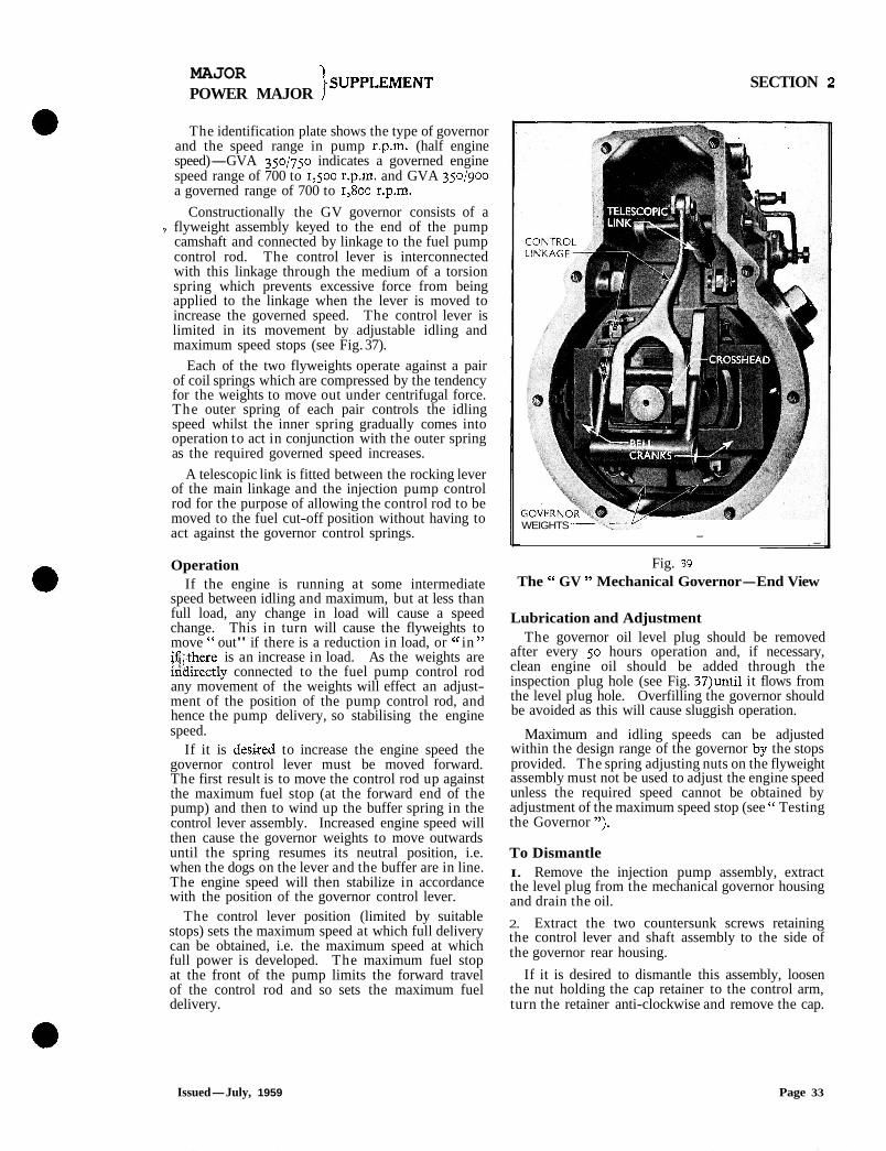
Constructionally the GV governor consists of a ? flyweight assembly keyed to the end of the pump
camshaft and connected by linkage to the fuel pump control rod. The control lever is interconnected with this linkage through the medium of a torsion spring which prevents excessive force from being applied to the linkage when the lever is moved to increase the governed speed. The control lever is limited in its movement by adjustable idling and maximum speed stops (see Fig. 37).
Each of the two flyweights operate against a pair of coil springs which are compressed by the tendency for the weights to move out under centrifugal force. The outer spring of each pair controls the idling speed whilst the inner spring gradually comes into operation to act in conjunction with the outer spring as the required governed speed increases.
A telescopic link is fitted between the rocking lever of the main linkage and the injection pump control rod for the purpose of allowing the control rod to be moved to the fuel cut-off position without having to act against the governor control springs.
Operation If the engine is running at some intermediate
speed between idling and maximum, but at less than full load, any change in load will cause a speed change. This in turn will cause the flyweights to move " out" if there is a reduction in load, or cc in " i4;there is an increase in load. As the weights are &Iirectly connected to the fuel pump control rod any movement of the weights will effect an adjust- ment of the position of the pump control rod, and hence the pump delivery, so stabilising the engine speed.
If it is desked to increase the engine speed the governor control lever must be moved forward. The first result is to move the control rod up against the maximum fuel stop (at the forward end of the pump) and then to wind up the buffer spring in the control lever assembly. Increased engine speed will then cause the governor weights to move outwards until the spring resumes its neutral position, i.e. when the dogs on the lever and the buffer are in line. The engine speed will then stabilize in accordance with the position of the governor control lever.
The control lever position (limited by suitable stops) sets the maximum speed at which full delivery can be obtained, i.e. the maximum speed at which full power is developed. The maximum fuel stop at the front of the pump limits the forward travel of the control rod and so sets the maximum fuel delivery.
WEIGHTS - .-
Fig. 39
The " GV " Mechanical Governor-End View
Lubrication and Adjustment The governor oil level plug should be removed
after every 50 hours operation and, if necessary, clean engine oil should be added through the inspection plug hole (see Fig. 37)until it flows from the level plug hole. Overfilling the governor should be avoided as this will cause sluggish operation.
Maximum and idling speeds can be adjusted within the design range of the governor by the stops provided. The spring adjusting nuts on the flyweight assembly must not be used to adjust the engine speed unless the required speed cannot be obtained by adjustment of the maximum speed stop (see " Testing the Governor ").
To Dismantle I. Remove the injection pump assembly, extract the level plug from the mechanical governor housing and drain the oil.
2. Extract the two countersunk screws retaining the control lever and shaft assembly to the side of the governor rear housing.
If it is desired to dismantle this assembly, loosen the nut holding the cap retainer to the control arm, turn the retainer anti-clockwise and remove the cap.
Issued-July, 1959 Page 33
MAJOR l SUPPLEMENT POWER MAJOR j
SECTION 2
Drive out.the taper pin retaining the buffer plate to the shaft and remove the buffer plate and spring. Withdraw the shaft from the control lever and the control lever from the bearing housing.
3. Unscrew the two hexagon-headed plugs from the rear half of the governor housing and push out the operating lever fulcrum pin.
4. Unscrew the bolts securing the two halves of the governor housing and remove the rear half.
5. Remove the clevis pin securing the rocking lever to the telescopic link and remove the rocking lever, operating lever and crosshead as an assembly.
If necessary further dismantle this assembly by rotating the crosshead until the flats on the pins line up with the slots in the ends of the rocking lever fork, then slide the crosshead out of the fork. Remove the split pin and extract the rocking lever fulcrum pin. 6. Remove the split pin and clevis pin securing the connecting link to the fuel pump control rod, extract the " E " clip, plain washer and " 0 " ring from one side of the connecting link cross-shaft and withdraw the cross-shaft from the housing.
Remove the telescopic link and connecting link as an assembly and dismantle, if necessary, by removing the pin securing the two links together.
The telescopic link may be further dismantled by compressing the plunger and spring until the plunger pin (inside the sleeve) lines up with the two holes drilled in the sleeve and then driving out the pin.
7. Remove the split pins, unscrew the nuts and remove one of the side plates from the bell cranks. Note that a flat!'&asher is fitted between each end of the side plates and the bell cranks. Remove the gudgeon pin and the governor operating spindle.
8. Remove the locking wire, unscrew the two bolts retaining the brass-flanged bush to the rear face of the governor hub, and detach the bush.
9. Unscrew the slotted nut securing the governor mass to the injection pump camshaft and remove the nut with special wrench (Tool No. T.9048). Extract the spring washer and screw the special puller (Tool No. T.9047) into the threaded centre of the governor hub. Tighten the centre screw of the tool to with- draw the governor mass from the injection pump cams haft.
10. Remove the remaining side plate and flat washers from the bellcrank fulcrum pins.
11. Remove the split pins and unscrew the spring adjusting nuts using special tongued tool (No. T.9049). Withdraw the spring retainers followed by the inner and outer springs and unscrew the stop nuts. Detach the spring collars, spring guide bushes and flat washers from the spring retaining pins on the governor hub.
12. Remove the split pins passing through the governor weights, extract the pins from the weights and detach the weights from the bellcranks.
13. To remove the bellcranks press out the bell- crank fulcrum pins from the governor hub.
NOTE.-In some instances the fulcrum pins are located in the governor hub by small dowels. Remove the dowels before pressing out the pins.
Inspection After the governor has been completely dismantled,
thoroughly clean and inspect all components. If the fulcrum pins, bushes or linkage components are worn they must be renewed, otherwise the accuracy of governing will be seriously affected.
The governor weights are supplied in pairs and should be used as such. Likewise each governor weight inner and outer spring are supplied as a matched pair but it is recommended that both pairs of springs are renewed if any one requires replace- ment.
To Reassemble I. Locate the bellcrank levers on the governor hub and press the fulcrum pins into position so that they are located centrally in the hub, retaining them with dowels if necessary. Take care not to damage the threads on the ends of the fulcrum pins or to distort the bellcrank levers. Ensure that the bellcrank levers move with perfect freedom on the pins without binding in any position.
2. Locate the governor weights over the spring retainer pins of the hub, position the bellcrank lever arms and install the short governor weight pins.
3. Align the holes in the pins with the holes in the weights and lock the pins in position with split pins through the weights and weight pins. Recheck that the weights and bellcrank levers are free to move.
4. Fit a flat washer, spring collar guide bush, spring collar and stop nut to each spring retaining pin on the hub. Securely tighten the stop nuts.
5. Install an inner and outer spring, spring retainer and adjusting nut on each spring retaining pin of the hub. Screw on the adjusting nuts until the outer springs are just retained by their free lengths without any pre-load. The top of the nuts must always be flush with or below the tops of the studs, but not more than two turns below. If this setting cannot be obtained renew the springs.
6. Fit a flat washer on each bellcrank lever fulcrum pin (one side only) and assemble the corresponding side plate, securing it in position with two castellated nuts which should be tightened securely and then split-pinned.
7. Locate the governor mass on the key in the camshaft, fit a spring washer and a special slotted nut. Tighten the nut to a torque of 45 lbs. ft. (6.2 kg.m.), using Tool No. T.9048 in conjunction with standard type torque wrench.
8. Install the flanged bush and secure to the governor hub with two hexagon-headed screws. Wire the bolt heads to retain them in position.
Page 34
MAJOR 1 -SUPPLEMENT
POWER MAJOR I SECTION 2
9. Insert the governor operating spindle in the bush and pass the gudgeon pin through the bellcrank levers and the spindle.
10. Fit flat washers and the remaining side plate to the bellcrank lever fulcrum pins and retain with two castellated nuts and split pins. Push in the operating spindle and check if any free movement exists in
"ither of the governor weights. Any such movement indicates a weak or incorrectly adjusted control spring.
11. If the telescopic link has been dismantled, place the spring seat on the plunger followed by the spring. Assemble the plunger to the sleeve and compress the assembly at the same time rotating the sleeve until the holes in the sleeve line up with the hole in the plunger. Drive the stop pin into position to give even protrusion each side of the plunger and check that the plunger is free to slide in the sleeve.
12. Attach the telescopic link to the centre hole of the connecting link with the appropriate clevis pin and split pin. The tongue on the sleeve locates on the same side as the circular boss of the connecting link.
13. Attach the forked end of the connecting link (circular boss to the left) to the fuel injection pump control rod and retain with a clevis pin and split pin.
14. Align the hole in the connecting link boss with the cross-shaft bores in the governor housing and assemble the cross-shaft. Assemble an " 0 " ring, flat washer and " E " clip to each end of the cross- shaft to retain it in position.
15. Assemble the rocking lever to the governor operating lever, retaining the rocking !ever fulcrum pin with a split pin. Assemble the crosshead to the rocking lever and insrall this assembly in the governor, sliding the crosshead into the annular groove in the governor operating spindle. Connect the upper end of the rocking lever to the telescopic link using an appropriate clevis pin and split pin.
16. Place a new gasket on the governor front housing flange and locate the rear half of the governor housing over the lower end of the governor operating lever. Assemble the operating lever fulcrum pin to the governor rear housing picking up the operating lever on the,pin.
17. Fully assemble the rear half of the governor housing and fit the appropriate retaining screws and spring washers.
18. Fit the operating lever fulcrum pin retaining plugs with a sealing washer under each plug.
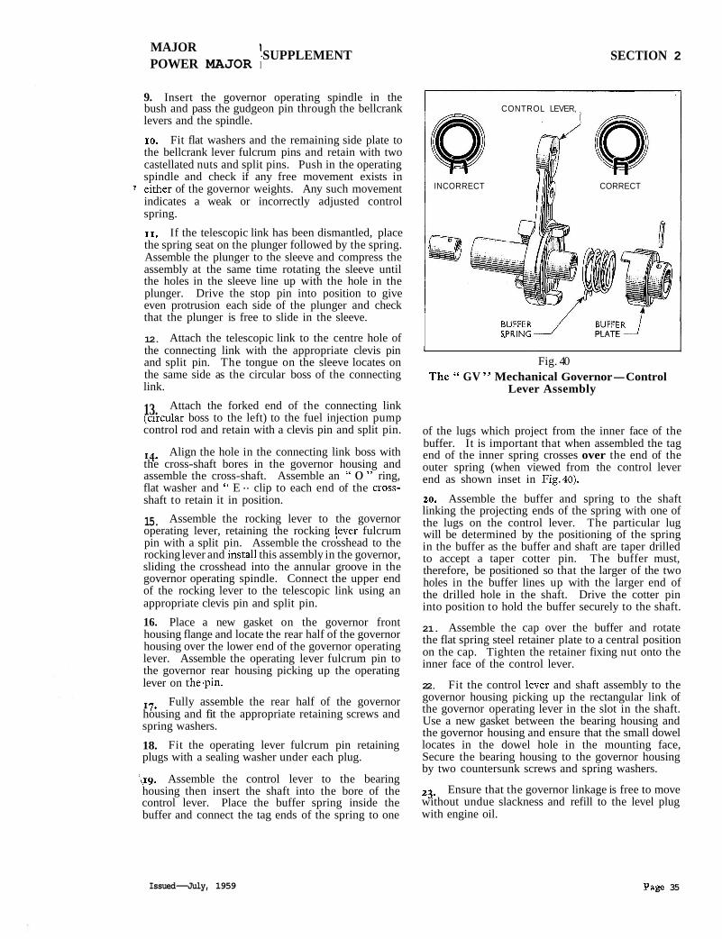
'l,~g. Assemble the control lever to the bearing housing then insert the shaft into the bore of the control lever. Place the buffer spring inside the buffer and connect the tag ends of the spring to one
I CONTROL LEVER,
INCORRECT CORRECT
BUFFER _I BURIRJ SPRING PLATE
l - Fig. 40
The " GV " Mechanical Governor-Control Lever Assembly
of the lugs which project from the inner face of the buffer. It is important that when assembled the tag end of the inner spring crosses over the end of the outer spring (when viewed from the control lever end as shown inset in Fig.40).
20. Assemble the buffer and spring to the shaft linking the projecting ends of the spring with one of the lugs on the control lever. The particular lug will be determined by the positioning of the spring in the buffer as the buffer and shaft are taper drilled to accept a taper cotter pin. The buffer must, therefore, be positioned so that the larger of the two holes in the buffer lines up with the larger end of the drilled hole in the shaft. Drive the cotter pin into position to hold the buffer securely to the shaft.
21. Assemble the cap over the buffer and rotate the flat spring steel retainer plate to a central position on the cap. Tighten the retainer fixing nut onto the inner face of the control lever.
22. Fit the control lever and shaft assembly to the governor housing picking up the rectangular link of the governor operating lever in the slot in the shaft. Use a new gasket between the bearing housing and the governor housing and ensure that the small dowel locates in the dowel hole in the mounting face, Secure the bearing housing to the governor housing by two countersunk screws and spring washers.
23. Ensure that the governor linkage is free to move without undue slackness and refill to the level plug with engine oil.
Issued-July, 1959 Page 35
MAJOR ' SUPPLEMENT POWER MAJOR j
SECTION 2
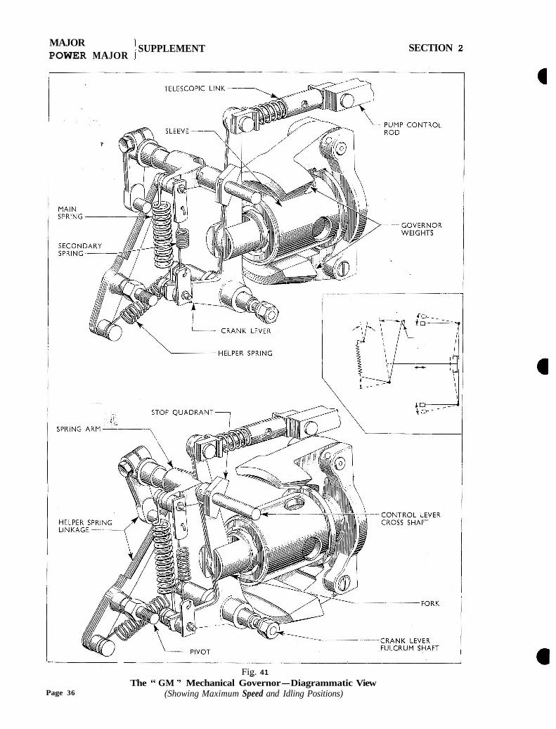
Fig. 41 - The " GM " Mechanical Governor-Diagrammatic View
Page 36 (Showing Maximum Speed and Idling Positions)

MAJOR POWER MAJOR
}SUPPLEMENT SECTION 2
" GM " TYPE MECHANICAL GOVERNOR This type of governor may be encountered giving
any one of three engine speed ranges, i.e. 500 to 1,500 r.p.m., 500 to 1,800 r.p.m. and 500 to 2,250 r.p.m. They are identical in construction apart from the flyweights, a lighter pair of weights being fitted to the 2,250 r.p.m. governor than to the 1,500 and 1,800 r.p.m. units (see Fig. 43. j. The weights used on the 1,506 and 1,800 r.p.m. units are identical and the variat~on in speed range is obtained by adjustment of the maximum speed stop screw on the governor housing. The same control springs are used on all three governors.
On the high speed unit, the type and the complete speed range in pump r.p.m. (half engine speed) is inscribed on a plate which is fixed to the rear half of the governor housing, i.e. GMVA 25011 125, indicating a governed engine speed range of 500 to 2,250 r.p.m.
On the two lower speed governors, although the minimum governed speed is still 250 r.p.m. (pump), the plate carries the inscription GMVA 750/900, indicating a governed maximum engine speed of either 1,500 or 1,800 r.p.m. It will therefore be necessary to determine which of these maximum speeds is required for the particular engine application before adjusting the maximum speed stop.
Constructionally, the G M governor consists of two wedge-shaped flyweights pivoting about pins which are secured to the governor hub, and this in turn is keyed and secured by a slotted nut to the fuel injection pump camshaft. Supported, and free to slide, on the hub is a sleeve, one end of which carries a forked
Fig.42 The " GM " Mechanical Governor
Issued-July, 1959
Fig.43 The " GM " Governor Weights
shaft in a ball bearing whilst the other end is in contact with the toes of the flyweights. A cranked lever, the longer arm of which is connected through the medium of a telescopic link with the fuel injection pump control rod, locates in the forked shaft and pivots on a fulcrum pin which is fixed to the governor housing. The shorter arm of the cranked lever is connected through a pair of tension springs with an arm which is fixed to the control lever cross-shaft. The control lever is limited in its movement by stop screws, in the rear of the governor, which bear against a stop quadrant fixed to the control lever cross-shaft, so setting the maximum and idling speeds.
The telescopic link between the cranked lever and the fuel injection pump control rod allows the control rod to be moved to the fuel cut-off position without having to act against the governor control springs.
Fitted externally is a helper spring which is connected through suitable linkage with the control lever in such a manner that the effort required to move the lever to obtain a. speed increase is relatively constant throughout the speed range.
Operation In operation, initial movement of the control lever
in a forward direction, to provide an increase in governed speed, loads the governor springs causing the cranked lever to pivot about the fulcrum pin, moving the hub sleeve forward against the toes of the weights and the injection pump control rod into
-the' maximum fuel position. As the engine speed rises, centrifugal force causes the flyweights to move
Page 37
MAJOR \SUPPLEMENT
POWER MAJOR J SECTION 2
out, so bringing the hub sleeve and injection pump control rod rearwards until the centrifugal force from the governor weights is balanced by the loading of the governor springs, thus stabilizing the engine speed in accordance with the position of the control lever.
Should the engine load decrease with the control lever$. the same position, engine speed will rise and cause the governor weights to move outwards, so moving the injection pump control rod towards the minimum fuel position, and vice versa. FigAl shows the relative governor weight and control rod positions when the engine is at idling and full load positions.
The main governor spring controls the idling and lower speeds of the governor and the secondary spring gradually comes into effect as higher speeds are attained.
Lubrication The governor should be lubricated every 50 hours
by adding clean engine oil through the combined oil filler and breather (see Fig.42). Remove the breather cap and the oil level plug provided near the bottom of the governor housing and add oil until it flows from this hole. Do not overfill, as this will cause sluggish governor operation.
T o Dismantle I. Unscrew the bolt retaining the control lever to the cross-shaft and remove the lever.
2. Remove the screws securing the governor rear housing to the front housing.
3. Pull away the governor rear housing assembly sufficiently to remove the self-locking nut from the set scrgw securing the crank lever to the telescopic link. Unscrew the set screw from the crank lever and completely remove the rear housing assembly.
4. Withdraw the hub sleeve complete with ball bearing and fork.
This assembly may be dismantled, if necessary, by pressing the bearing and fork assembly from the housing and then pressing the fork from the bearing. Note the shims fitted between the fork and the bearing to provide a specified dimension (see assen~bly instructions) between the inside of the fork and the rear flange of the front governor housing.
5. Using special slotted wrench (Tool No. 17.9048), remove the nut securing the governor weight assembly to the camshaft and remove the spring washer.
6. Screw the special extractor (Tool No. T.9047) into the hub of the governor weight assembly and tighten the centre screw of the tool to withdraw the assembly from the camshaft.
NOTE.-The hub and governor weights are serviced as a balanced assembly and no attempt should be made to dismantle.
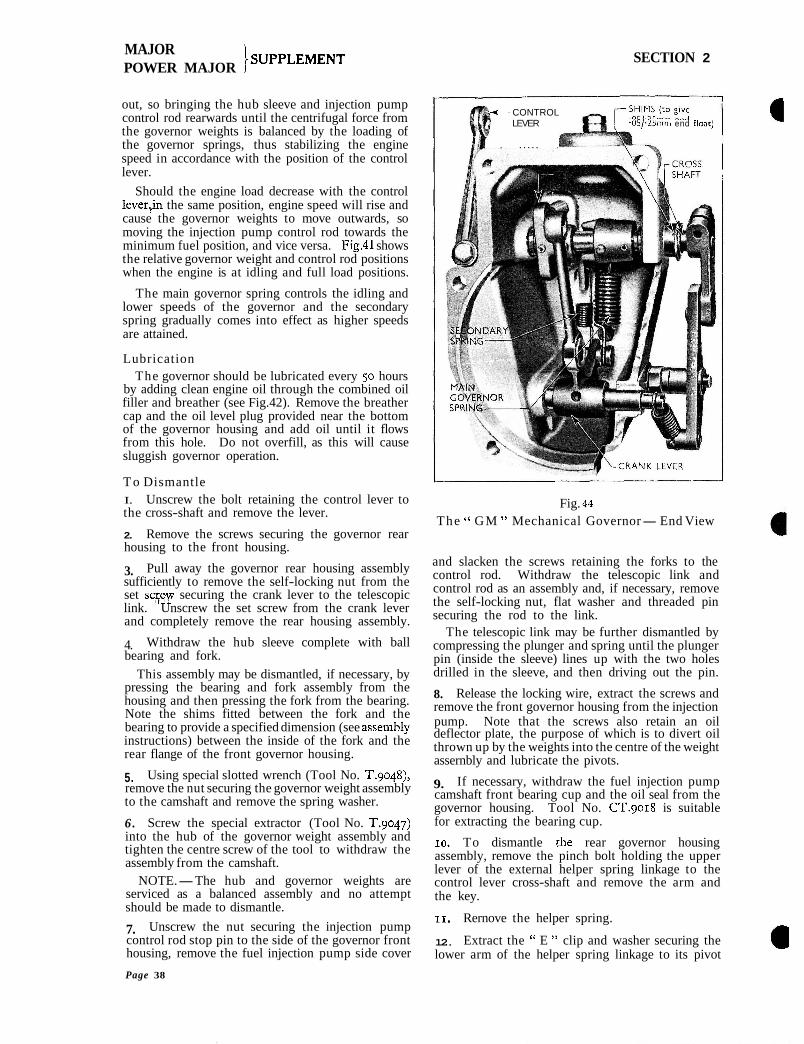
7. Unscrew the nut securing the injection pump control rod stop pin to the side of the governor front housing, remove the fuel injection pump side cover
- CONTROL LEVER .05/.25mni end flosc)
. . . . . . .
Fig. 44
The " GM " Mechanical Governor-End View
and slacken the screws retaining the forks to the control rod. Withdraw the telescopic link and control rod as an assembly and, if necessary, remove the self-locking nut, flat washer and threaded pin securing the rod to the link.
The telescopic link may be further dismantled by compressing the plunger and spring until the plunger pin (inside the sleeve) lines up with the two holes drilled in the sleeve, and then driving out the pin.
8. Release the locking wire, extract the screws and remove the front governor housing from the injection pump. Note that the screws also retain an oil deflector plate, the purpose of which is to divert oil thrown up by the weights into the centre of the weight assernbly and lubricate the pivots.
9. If necessary, withdraw the fuel injection pump camshaft front bearing cup and the oil seal from the governor housing. Tool No. CT.9018 is suitable for extracting the bearing cup.
10. To dismantle the rear governor housing assembly, remove the pinch bolt holding the upper lever of the external helper spring linkage to the control lever cross-shaft and remove the arm and the key.
11. Rernove the helper spring.
12. Extract the " E " clip and washer securing the lower arm of the helper spring linkage to its pivot
Page 38
MAJOR ' SUPPLEMENT POWER MAJOR \ SECTION 2
pin and remove the arm. If necessary, straighten the locking tab and unscrew the pivot pin from the governor housing.
13. Extract the " E " clip and remove the lower plate connecting the secondary spring to the crank lever.
14. Remove the secondary spring and the spacer from the crank lever.
15. Remove the governor main spring.
16. Extract the " E " clip, spring connecting plate (upper) and spacer from the spring arm pin.
17. Remove the spring connecting pins from the spring arm and crank lever.
18. Remove the self-locking nut and copper washer from the crank lever fulcrum shaft, withdraw the shaft from the housing and remove the crank lever.
19. Tap out the pins securing the stop quadrant and spring arm to the control lever cross-shaft, remove the " E " clips, flat washers and " 0 " sealing rings and withdraw the cross-shaft spring arm and stop quadrant. Note that shims may be fitted between the flat washers and the cross-shaft bushes to control end-float of the shaft.
To Reassemble I. Insert the control lever cross-shaft in the rear governor housing picking up the stop control quadrant 2nd the spring arm on the shaft. Pin the quadrant and arm to the shaft.
2. Place new " 0 " rings in the recess of each cross-shaft bush, assemble a flat washer and " E " clip on each end of the shaft and check the end-float gf the shaft. Fit shims as necessary between the fl8t washer and the bushes to restrict the end-float to within .o5 to .25 mm.
3. Fit a new " 0 " sealing ring to the groove in the crank lever fulcrum shaft and insert the shaft in the housing picking up the crank lever. Secure the shaft in position with a self-locking nut and a copper washer.
4. Replace the governor spring connecting pins to the crank lever and spring arm making the assemblies so that the heads of the pins are to the right when looking into the housing.
5. Fit a spacer, the longer of the two spring connecting plates and an " E " retaining clip to the spring arm pin.
6. Install the main governor spring, locating the hooked ends in the grooves immediately behind the heads of the crank lever and spring arm connecting pins.
7. Attach the shorter spring connecting plate to one end of the secondary spring and attach the other end of the spring to the longer plate.
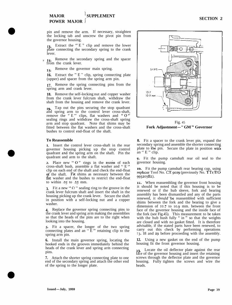
Fig. 45
Fork Adjustment-" GM " Governor
8. Fit a spacer to the crank lever pin, expand the secondary spring and assemble the shorter connecting plate to the pin. Secure the plate in position witi an " E " clip.
9. Fit the pump camshaft rear oil seal to the governor housing.
10. Fit the pump camshaft rear bearing cup, using replacer Tool No. cT.9019 (previously No. TTr/DD 993203B2).
11. When reassembling the governor front housing it should be noted that if this housing is to be renewed or if the hub sleeve, fork and bearing assembly has been dismantled and any of the parts renewed, it shouldbbe reassembled with sufficient shims between the fork and the bearing to give a dimension of 10.7 to 10.9 mm. between the front face of the governor housing and the inside face of the fork (see Fig.45). This measurement to be taken with the hub bush fully " in " so that the weights are closed and with no gasket fitted. It is therefore advisable, if the stated parts have been renewed, to carry out this check by performing operations 13, 18 and 19 before proceeding with the assembly.
12. Using a new gasket on the end of the pump housing fit the front governor housing.
13. Locate the oil deflector plate against the rear face of the governor housing and insert the retaining screws through the deflector plate and the governor housing. Fully tighten the screws and wire the heads.
Issued-July, 1959 Page 39

MAJOR SUPPLEMENT POWER MAJOR j
SECTION 2
14. If the telescopic link has been dismantled, place the spring seat on the plung& followed by the spring. Fit the plunger to the sleeve and compress the assembly, at the same time rotating the sleeve until the holes in the sleeve line up with the hole in the plunger. Drive the stop pin into position to give even protrusion each side of the plunger and check that the plung$r is free to slide in the sleeve.
15;. Attach the telescopic link to the rear of the pump control rod by means of the appropriate flat washer and self-locking nut.
16. Assemble the control rod and telescopic link assemblies to the pump, picking up the control rod forks. Ensure that the cut-out machined in the front end of the control rod faces the operating side of the excess fuel and stop device. Locate No. I fork approximately I mm. from the end of the square section at the front of the rod and roughly dign the remaining elements at the same angle. The final position of the forks will be established when the pump is calibrated.
17. Replace the injection pump control rod stop pm in the governor front housing and secure with the appropriate nut.
18. Fit the woodruff key to the pump camshaft, install the governor weights and hub assembly (serviced as a balanced assembly) and retain with a spring washer and special slotted nut. Using Tool No. T.9048 and a torque wrench tighten the nut to a torqde of 45 lbs. ft. (6.2 kg.m.).
19. Fit the hub sleeve, fork and bearing assembly and ensure that it is free to slide on the hub.
20. Locate a new gasket on the rear flange of the governor front ,h,pusing and connect the upper end of the crank lev& (in the rear housing) with the telescopic control link using the appropriate threaded pin and self-locking nut.
21. Fully assemble the governor rear housing, insert and fully tighten the retaining screws.
22. Place a locking tab on the helper spring lever pivot pin and screw it into the governor rear housing. Bend over the tabs of the washer to retain it in position.
23. Assemble the helper spring lower lever to the pivot pin and retain with a flat washer and " E " clip. 24. Install the helper spring between the crank lever fulcrum shaft and the lower lever of the external linkage.
25. Place a woodruff key in the control lever cross-shaft and assemble the upper lever of the helper spring linkage. Ensure that there is a clearance of I to 2 mm. between the inside edge of the upper lever and the outside edge of the lower lever. 26. Tighten the pinch bolt to retain the upper lever in position.
27. Assemble the control lever to the cross-shaft and tighten the fixing bolt.
28. Refill the governor to the level plug with clean engine oil.
29. Calibrate the pump and test the governor.
TESTING THE MECHANICAL GOVERNOR
The operation of the Mechanical Governor can be most satisfactorily tested on a variable speed calibrating machine but should this equipment not be available it is possible to check and adjust the maximum and idling speed on the engine to which it is fitted. The later procedure will, of course, only be satisfactory providing the engine itself is in good condition.
To check the maximum and idling speeds on a variable speed machine, mount the injection pump and governor assembly on the machine, remove the inspection cover from the pump and hold the governor control lever in the. maximum speed position. Slowly increase the speed of the machine and note the speed at which the control rod starts to move towards the fuel cut-off position. This should correspond to the maximum speed indicated on the governor housing plate.
Decrease the speed slightly and observe if the control rod moves immediately towards the minimum fuel position. Any sluggishness in response indicates internal stiffness in the governor or binding of the pump control rod and this condition should be corrected before making adjustments.
If the response is satisfactory and the maximum governed speed is incorrect, remove the seal from the maximum speed stop screw, back-off the locknut and adjust the stop to obtain the specified speed.
Re-tighten the locknut then wire and seal the stop to prevent arbitrary adjustment by operators, which could cause consequential damage if the speed is increased beyond that specified.
On GV pumps it is possible to also make a limited adjustment on the control springs by removing the inspection plug and screwing the adjusting nut " I n" to increase, or " Out" to decrease, the governed speed. Under no circumstances, however, should the nuts be screwed out beyond the ends of the threaded spring retaining pins or below two threads from the flush position. Ensure that the split pins are replaced to hold the nut in position after completing the adjustment.
Having set the maximum speed the machine should be set to run slightly below the specified idling speed of the governor (350 r.p.m. for GV governors-250 r.p.m. for GM governors). I t may be necessary to change the driving belt of the machine to a lower speed pulley to enable this check to be carried out. Set the governor control lever in the minimum fuel position, gradually increase the speed of the machine and again note the speed at which the injection pump control rod moves towards the fuel cut-off position. Adjust the idling speed stop as necessary.
Page 40

MAJOR '\
POWER MAJOR I SUPPLEMENT SECTION 2
If the tests and adjustments are to be made on the engine the same procedure applies using a tachometer on either the engine crankshaft or crankshaft pulley belt as a guide to speed.
PHASING AND CALIBRATING THE FUEL PUMP (when fitted with Mechanical Governor)
The method to be used when calibrating a fuel injection pump incorporating a mechanical governor differs slightly from that published for performing similar operations on one fitted with a pneumatic governor. Phasing may be checked with the unit mounted on the calibrating machine but should any discrepancies exist it will be necessary to remove the rear governor housing and the injection pump control rod to gain access to the phasing spacers.
The variable speed calibrating machine will enable all tests to be carried out on the pump and the governor. Where however the original approved fixed speed machine CT.gooo (previously numbered TTr1 DD.gg31oo) is the only one available it may be adapted to enable calibration of the pump to be performed. I t is not suitable for checking the mechanical governor.
As the mechanical governor projects below the base of the pump it will require mounting on the CT.gooo machine in such a manner that the governor overhangs the end of the mounting plate. This
involves drilling the mounting plate and inserting a suitable extension for the drive to the pump.
The necessary parts to make the adaption can be supplied by Messrs. V. L. Churchill & Co. under Tool No. CT.gooo-4 d consisting of a coupling and shaft assembly, CT.gooo-4 a template for drilling the mounting plate, CT.gooo-2 consisting of a movable coupling, fibre coupling and fixed coupling. The CT.gooo-a will have already been supplied to those dealers who have adapted this machine to suit the Fordson Dexta fuel injection pump. Fig. 40 shows the build-up of the drive.
Calibration When calibrating disregard the first set of readmgs
and balance the elements so that they all deliver the same amount of fuel for an average of four readings. Allow 10 secs. for the fuel to settle in the tubes after delivery and take the reading from the bottom of the curve of the fuel surface after it has settled. Allow a constant drain period of 10 secs. when emptying on each occasion. I. After mounting the pump and governor on the calibrating machine turn on the fuel fced and loosen the bleed screw on the pump body to bleed the system of air. Re-tighten the scrcw and run the calibrating machine at 600 r.p.m. for at least 10 mins. to warm the pump and oil to a temperature of 65 to 70°F. (18 to 21°C.).
CT. 9600- 2
'MOVABLE FIBRE FIXED ' COUPLING COUPLING COUPLING
CT. 9000-'4/d COUPLING AND SHAFT SCREW
ASSEMBLY
Fig. 46
Mechanical Governor Drive for CT.gooo Calibrating Machine
Issued-July, 1959 Page 41

MAJOR I
POWER MAJOR 1 SUPPLEMENT SECTION 2
2. Set No. I control fork so that it is approximately I mm. from the square section at the excess fuel end of the pump control rod.
3. Run the pump at 600 r.p.m. with the control lever in the maximum speed position and collect 200 injections of fuel from No. I element in the graduated test tube. Adjust the maximum fuel stop screw at the ffont of the pump to obtain a fuel delivery from this element of 11 .6 to I I .8 c.cs.
Operate the excess fuel device and ensure that the fork securing screw does not foul on the hexagon head of the bolt which secures the maximum fuel and stop device to the pump.
4. Balance the remaining elements by adjusting the position of the forks on the pump control rod so that the average of four deliveries, each of 200 injec- tions at 600 r.p.m. from all elements is between 11.6 and 11.8 c.cs.
5. When the calibration is satisfactory, run the machine at 200 r.p.m. and check the delivery over 200 injections. Delivery drop on each element should not exceed 2.5 c.cs. below the figure obtained at 600 r.p.m. If the drop exceeds 2.5 c.cs. it indicates a worn element. If the delivery at 200
r.p.m. exceeds that obtained at 600 r.p.m. fit a new delivery valve assembly to the element affected and re-calibrate at 600 r.p.m. and recheck at 200 r.p.m.
6. Check at 600 r.p.m. that when the excess fuel device is operated, all elements deliver at least 19 c.cs. of fuel over 200 injections. It is not necessary for all elements to deliver exactly the same amount.
7. With the control lever in the maximum fuel position increase the speed of the calibrating machine to the maximum specified on the governor plate and adjust the maximum speed stop screw as previously described under "Testing the Mechanical Governor." Tighten the locknut and seal the stop in this position.
8. Adjust the governor idling speed as described under " Testing the .Mechanical Governor."
NOTE.-Operations 5 and 6 can only be carried out on calibrating machines fitted with a variable speed control.
g. With the pump running at idling speed check that the delivery from all elements ceases when the stop control lever is operated.
10. Before replacing the pump inspection cover ensure that the fork screws are securely tightened onto the control rod.
11. Irrespective of the setting of the idling speed stop, final idling adjustment should be made after the unit is fitted to the particular engine on which it is to operate.
I SPECIFICATIONS /I / -
GV MECHANICAL GOVERNOR
Maximum Speed (Governor r.p.m.) . . Idling Speed (Governor r.p.m.) . . Inner Spring Test Length . . . .
i Colour Identification-Inner Spring Inner Spring Test Load . . . . Colour Identification-Outer Spring Outer Spring Test Length . . . . Outer Spring Test Load . . ' . .
GM MECHANICAL GOVERNOR
Mvrimum Speed (Governor r.p.m.) . . Idling Speed (Governor r.p.m.) . . Governor Weight . . . . . . Main Spring Rate . . . . . . Colour Identification-Main Spring Secondary Spring Rate . . . . Colour Identification. . . . . . Helper Spring Rate . . . . . .
. . 750
. . 350
. . 20 mm.
. . Blue and Brown
.. 23lb~.4$OZS.t024lb~, 1 2 2 0 Z S .
(10.567 to 10.774 kg.) . . Red and Blue . . 25 mm. . . 5 lbs. 4 ozs.
(2.381 kg.)
. . . . . . . . .- 750
. . . . . . . . . . 250
. . . . . . . . . . Heavy
350 20 mm.
Blue and Yellow 39 Ibs. to 43 Ibs.
(17.69 to 19.50 kgs.) Red, Blue and White
36.75 Inm. 4 lbs. g ozs. (2.069 kg.)
900 I I25 250 250 Heavy Light
44 lbs./in. (7.85 kg./cm.) . . Red and Yellow 26 Ibs./in. (4.64 kg./cm.) . . Blue and Yellow 40 Ibs./in. (7.14 kg./cm.)
Page 42
SUPER MAJOR SUPPLEMENT SECTION 2
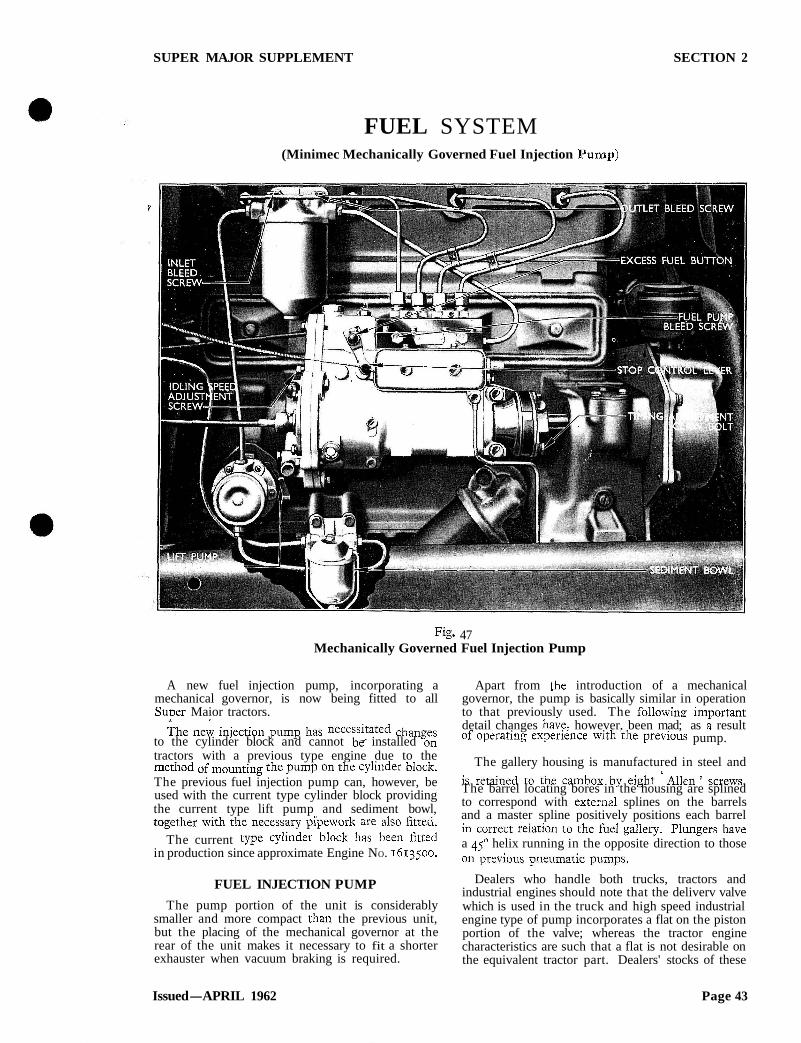
FUEL SYSTEM (Minimec Mechanically Governed Fuel Injection Pump)
Fig. 47 Mechanically Governed Fuel Injection Pump
A new fuel injection pump, incorporating a Apart from the introduction of a mechanical mechanical governor, is now being fitted to all governor, the pump is basically similar in operation S u ~ e r Maior tractors. to that previously used. The followinrr im~ortant
The new injection pump has changes detail changes ha;e, however, been mad; as a result to the cylinder block and cannot be+ installed on of operating experience with the previous pump. tractors with a previous type engine due to the The gallery housing is manufactured in steel and method of mounting the pump on the cylinder block. is retained to the cambox by eigllt Alien ' screws, The previous fuel injection pump can, however, be used with the current type cylinder block providing The barrel locating bores in the housing are splined
the current type lift pump and sediment bowl, to correspond with exterml splines on the barrels and a master spline positively positions each barrel
tagether the necessary pipework are fitted' in relation to the fuel gallery. Plungers have The current type cylinder block has been fitted a 45' helix running in the opposite direction to those
in production since approximate Engine NO. 1613500. On previous pneumatic pumps.
FUEL INJECTION PUMP Dealers who handle both trucks, tractors and industrial engines should note that the deliverv valve
The pump portion of the unit is considerably which is used in the truck and high speed industrial smaller and more compact than the previous unit, engine type of pump incorporates a flat on the piston but the placing of the mechanical governor at the portion of the valve; whereas the tractor engine rear of the unit makes it necessary to fit a shorter characteristics are such that a flat is not desirable on exhauster when vacuum braking is required. the equivalent tractor part. Dealers' stocks of these
Issued-APRIL 1962 Page 43
SUPER MAJOR SUPPLEMENT SECTION 2
Page 44

SUPER MAJOR SUPPLEMENT SECTION 2
parts should therefore be strictly segregated to eliminate the possibility of an incorrect part being used.
Delivery valve guides are of the conventional pattern but nylon sealing washers are used between guide and holder. Delivery valve guide holders are serrated on their outside diameter and locked by semi-circular retainers, each pair of holders being held by a pair of retainers clamped to the holder serrations by a single bolt and spring washer.
Plunger springs locate directly onto the underside of the gallery housing and no spring discs are used at this location. The spring lower discs have been designed so that they can be supplied in graded thicknesses so obviating the necessity for shimming the plunger arm to control clearance between the plunger and the spring lower disc.
As on previous pumps, each tappet assembly is built up with a double roller cam follower running on a pin in the tappet body, and a phasing spacer retained by a circlip. The tappet body, however, has a flat machined on its outside diameter which on assembly bears against " T " shaped locators, one of which is inserted in slots machined betweeneach pair of tappet bores in the cambox. The tappets are therefore prevented from rotating during operation thus reducing wear between the tappets and the pump body.
Whilst the control rod serves the same function as on previous pumps it has been redesigned to provide a link-up with the mechanical governor. Where the rod enters the governor housing it runs in a square bore bush which is positioned in the housing by a small tension pin.
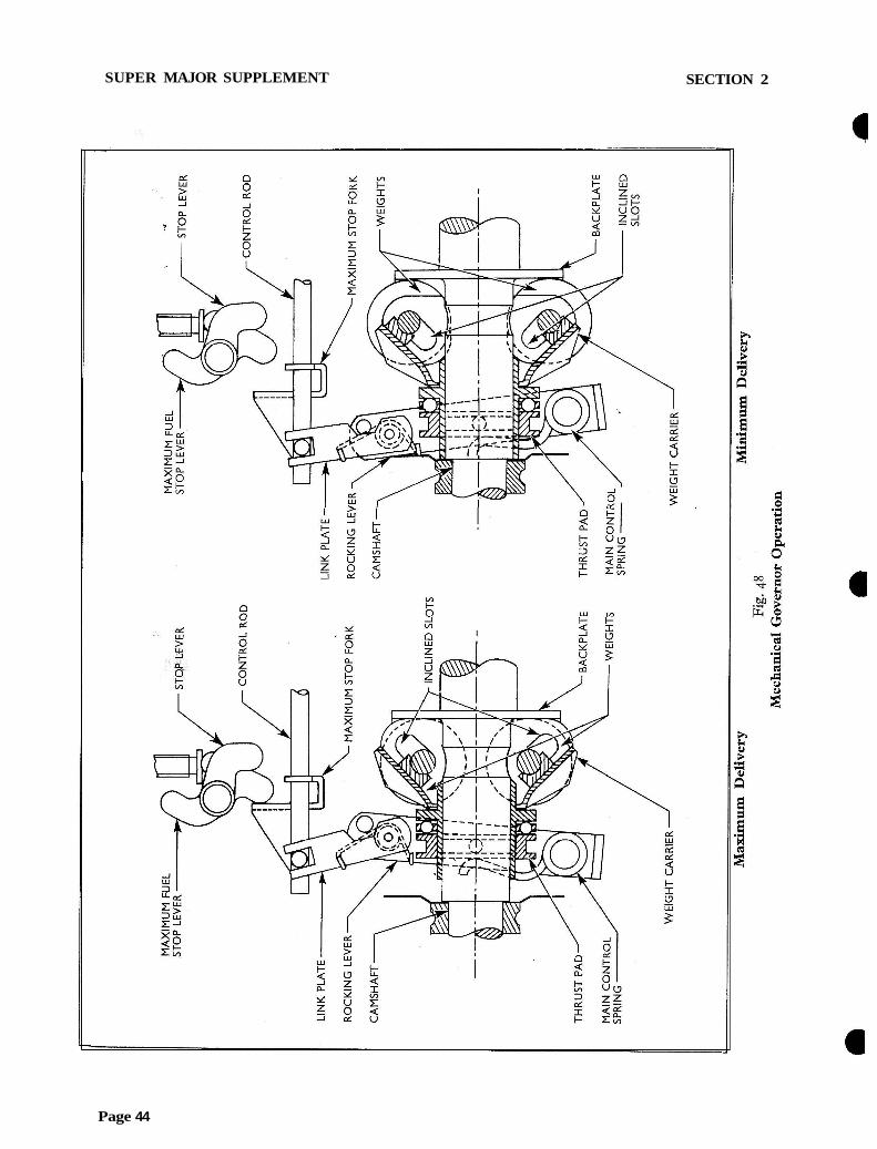
THE GOVERNOR
The pump camshaft is extended rearwards to carry the governor weight assembly which consists of a carrier supporting four weights in inclined slots, the carrier and weight assembly being free to move axially along the camshaft.
The design of the camshaft is such that the complete governor and camshaft is supported within the bearing span, bearings being located at the front of the pump body and in the governor rear cover plate.
The weights are enclosed by, and in constant contact with, a shaped backplate which is dowelled and bolted to a flange on the camshaft.
Interposed between the carrier and the governor main control spring, which is retained by a special bolt and locknut to a cross-shaft in the base of the governor housing, is a thrust bearing and plate. This plate is engaged through pins with a rocking lever which pivots on the control spring cross-shaft and is connected by a spring-loaded link with the fuel injection pump control rod.
VOLUME REDUCER DELIVERY VALVE HOLDER
ELIVERY VALVE
DELIVERY VALVE SPRING VALVE GUIDE
BLEED SCREW
C O N T R O L FORK CLAMP SCREW
C O N T R O L R O D PLUNGER RETURN SPRING
C O N T R O L FORK B O I T O M SPRING PLATE
TAPPET ASSEMBLY
Fig. 49 Cross Section.Through Cambox and Pumping Element
Issued-APRIL 1962 Page 45
SUPER MAJOR SUPPLEMENT SECTION 2
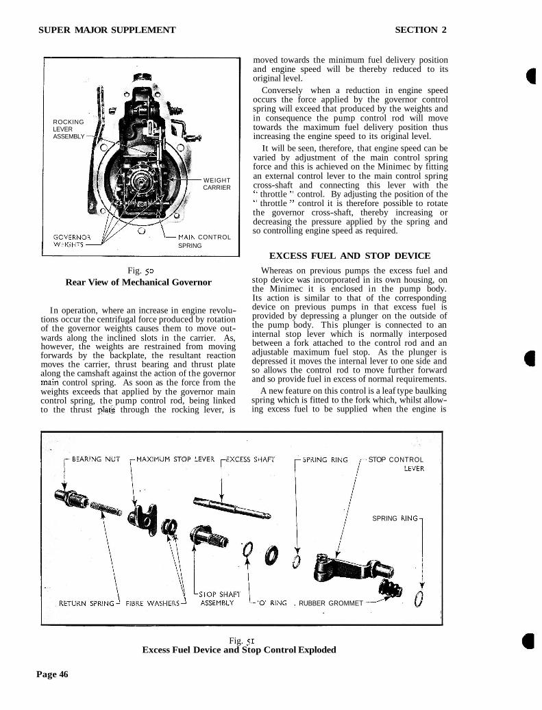
ROCKING LEVER ASSEMBLY
WEIGHT CARRIER
I gYG"Eypfl \- MAIN CONTROL SPRING
Fig. 50 Rear View of Mechanical Governor
In operation, where an increase in engine revolu- tions occur the centrifugal force produced by rotation of the governor weights causes them to move out- wards along the inclined slots in the carrier. As, however, the weights are restrained from moving forwards by the backplate, the resultant reaction moves the carrier, thrust bearing and thrust plate along the camshaft against the action of the governor mzin control spring. As soon as the force from the weights exceeds that applied by the governor main control spring, the pump control rod, being linked to the thrust $l&@ through the rocking lever, is
moved towards the minimum fuel delivery position and engine speed will be thereby reduced to its original level.
Conversely when a reduction in engine speed occurs the force applied by the governor control spring will exceed that produced by the weights and in consequence the pump control rod will move towards the maximum fuel delivery position thus increasing the engine speed to its original level.
It will be seen, therefore, that engine speed can be varied by adjustment of the main control spring force and this is achieved on the Minimec by fitting an external control lever to the main control spring cross-shaft and connecting this lever with the " throttle " control. By adjusting the position of the " throttle " control it is therefore possible to rotate the governor cross-shaft, thereby increasing or decreasing the pressure applied by the spring and so controlling engine speed as required.
EXCESS FUEL AND STOP DEVICE
Whereas on previous pumps the excess fuel and stop device was incorporated in its own housing, on the Minimec it is enclosed in the pump body. Its action is similar to that of the corresponding device on previous pumps in that excess fuel is provided by depressing a plunger on the outside of the pump body. This plunger is connected to an internal stop lever which is normally interposed between a fork attached to the control rod and an adjustable maximum fuel stop. As the plunger is depressed it moves the internal lever to one side and so allows the control rod to move further forward and so provide fuel in excess of normal requirements.
A new feature on this control is a leaf type baulking spring which is fitted to the fork which, whilst allow- ing excess fuel to be supplied when the engine is
STOP CONTROL
SPRING RlNG
'0' RlNG . RUBBER GROMMET
Fig. 51 Excess Fuel Device and Stop Control Exploded
Page 46

SUPER MAJOR SUPPLEiMENT SECTION 2
Fig. 52 Injection Pump Lubrication
stopped, prevents the control rod from being moved to the excess fuel position when the engine is running. This of course eliminates the production of excessive black smoke by operators misguidedly fixing the device in the excess fuel position in an endeavour to obtain more power from the engine.
When starting the engine " open the throttle " in order to tension the main control spring and move tK&-thrust pad, weight carrier and pump control rod forward to the maximum fuel position-or to the excess fuel position when the excess fuel device is operated.
The stop device is of conventional design in that an external lever is connected to a second internal lever which is mounted alongside the internal excess fuel device lever in which position it also acts on the control rod fork. Thus rotation of the external lever moves the control rod positively to the fuel cut-off position to stop the engine.
PROOFMETERS
Excepting where an exhauster is fitted thc proof- meter drive is taken from the end of the camshaft which has necessitated the introduction of a new proofmeter and cable. Where, however, an exhauster is fitted, the existing proofmeter and cable will continue to be used, the drive being taken as before from the engine auxiliary drive shaft.
AUXILIARY DRIVE SHAFT
A new auxiliary drive shaft has been introduced for tractors fitted with the mechanical governor only.
T h ~ s shaft IS not only longer than the shafts used on previous englnes but the keyways, whlch were previously In h e , are now 10' offset In relation, one to the other, and in consequence the new shaft IS not sultable for use on previous engines.
ROUTINE SERVICING
Fuel filter elements and injector changes should be carried out every 600 hours as before, whilst the sediment bowl should be removed and the screen cleaned whenever an accumulation of moisture or sediment is observed through the glass container.
The integral cambox and governor housing is designed to enable a single oil level to be used. Every 200 hours remove the filler, level and drain plugs from the cambox and drain off the old oil. This operation should preferably be carried out after the tractor has been running, the oil will then be hot and will drain out. easily.
Replace the drain plug and add clean engine oil through the filler plug up to the level plug. Approximately five-eighths of a pint is required. Replace the level and filler plugs and wipe any surplus oil from the outside of the housing.
BLEEDING THE FUEL SYSTEM
If the fuel system has been disconnected at any point or the fuel tank allowed to run dry, it will be necessary to bleed the system to remove air which will have entered.
Procedure is identical with previous pumps excepting that when bleeding the fuel pump gallery the bleed screw at the governor end of the pump gailery is the one which should be used.
ENGINE TIMING AND SPEED SETTING
The characteristics of the mechanical governor are such that maximum performance is obtained by timing the engine at 21" B.T.D.C.
Engine idling speed is adjusted by means of a stop screw located in the governor rear end plate where it makes contact with the rear side of the governor main control lever. T o effect an adjustment first warm the engine up to its normal operating tempera- ture, then slacken the locknut on the adjusting screw and position the screw to produce an engine idling speed of 550 r.p.m. (approx.).
Maximum engine speed is set by positioning the adjusting screw located on the engine side of the pump where it makes contact with the front sids of the main control lever. This screw is set and sealed in production to give a maximur,l engine " no-load " speed of 1800 to 1820 r.p.m. Normally this screw setting should not be altered unless the pump has been overhauled when it should be adjusted with the aid of a variable speed calibrating machine. Where
Page 47

SUPER MAJOR SUPPLEMENT SECTION 2
F% 53 , Injection Pump Installed o n Fixed Speed
Calibrating Machine
such equip&;&i is not available it is poss~ble to obtain a working setting by adjusting the screw with the pump assembled to the engine but an accurate tachometer should be used-arbitrary adjustment should not be made under any circumstances-and it should be appreciated that using this method is not nearly as accurate as setting the governor on a variable speed machine.
Where a variable speed machine is available, mount the pump on the machine, remove the inspection cover from the side of the pump, extract the hexagon- headed screws securing the cover plate retainers and withdraw the retainers. These locate in slots in the pump housing and must be rotated through go" before they can be removed.
Check the phasing and calibration and adjust as necessary before attempting to adjust the governor speed. Hold the main control lever fully forward against the maximum speed stop screw and slowly increase the speed, at the same time observing the control rod. Note the speed at which the control rod starts to move towards the governor, i.e. towards the minimum fuel delivery pobition. Initial movement should start at approxmately 860 r.p.m. (pump) and full fuel cut-off shoalcl. take place at goo to g10 r.p.m. Adjust the rnaxirnum speed stop scrc\v if necessary.
PHASING AND CALIBRATING MACHINES
A variable speed machine is necessary for complete, accuiate servicing of any fuel injection pump with a mechanical governor. (It also enables work to be uadertaken on distributor type pumps.)
Phasing and calibration of the pump can, how- ever, be carried out with the original fixed speed Churchill machine (Tool No. T r I/DD 993100) provilng a slot is cut across the pump mounting table to provide clearance for the mounting boss at the forward end of the pump and that an additional pair of holes are drilled in the mounting table for the fixing bolts. In addition a special drive shaft is required between the pump and the driving coupling of the machine. A jig is available to enable Dealers in possession of this machine to rework the mounting table.
Dealers who possess the Churchill 9000 machine or the Hartridge Minor will be able to obtain a Universal Pump Bracket (e.g. the Hartridge " Junior " Bracket) which will convert these machines for any base mounted Fordson tractor pump.
PHASING T H E MINIMEC
The procedure to be followed when phasing is basically the same as with previous fuel injection pumps but the following points should be noted.
When phasing a pump without having completely dismantled it for overhaul the gallery housing may be removed from the pump body to gain access to, and remove, the plunger springs and spring discs and also to change the phasing spacers in the following manner :
I . Place the pump assembly on the bench so that
Fig. 54 Separating Pump Body and Cambox
Page 48

SUPER MAJOR SUPPLEMENT SECTION 2
it is inclined at an angle with the inspection cover aperture downwards.
2 . Remove the eight Allen screws securing the gallery housing to the pump body.
3. Rotate the gallery housing downwards whilst holding the body at the same angle. This will enable the plunger arms to disengage from the control rod forks and allow the gallery, complete with barrels, plungers and springs, to be with- drawn from the body.
Use the same mezhod to reassemble the parts after adjusting and phasing, ensuring that the plunger arms are correctly located in the control forks.
The governor main control lever must be fixed against the maximum speed stop screw to hold the plungers in the maximum fuel delivery position whilst phasing is being carried out. Previous instructions have dealt with calibrating machines not fitted with pressure phasing facilities and it has been necessary to remove the delivery valve, delivery valve spring and volume reducer from each element as it is phased. This procedure is not necessary where pressure phasing is available.
When phasing on a high speed machine (i.e. electronic phasing) it is advisable to ensure that an adequate supply of lubricating oil is in the pump and governor before operating the machine.
When phasing this type of pump, using new tappets or plunger and barrels a phasing spacer of intermediate thickness, marked 8, should be used for the initial check.
Fig. j5 Checking Pump Phasing
Issued-APRIL 1962
Fig. 56 Injection Pump Installed on Variable Speed
Calibrating Machine
CALIBRATING THE MINILIEC
When calibrating, the following points should be observed :
I. Ensure that there is sufficient lubricant in the pump body to provide adequate lubrication for the pump and governor components.
2 . Ensure that the delivery valve holder retainers are replaced and tightened before running the pump, either on a calibrating machine or eGgine.
Part No.
CONN-gC586-A
CONN-gC586-B
CONN-gC586-C
CONN-gC586-D
CONN-gC586-E
Marking ---
G A
7
8
9A
I 0
Phasing Spacer
Thickness
.I~I-.173 in. (4.35-4.40 mm.)
.175-.177 m. (4.45-4.50 mm.)
.179-.I~I in. (4.55-4.60 mm.)
.183-.185 in. (4.65-4.70 mm.)
.IQ-.18g in. (4.75-4.80 mm.)
Identification
Page 49
SUPER MAJOR SUPPLEMENT SECTION 2
The governor main control lever must be fixed in the maximum fuel delivery position, i.e. against the maximum speed stop screw.
Set the front control fork (No. I) at a distance of 0.02 in. (0.5 mm.) from the end of the square section of the control rod and adjust the maximum fuel stop SO that the element delivers between 12.8 and 13.2 C.C. of fuel during too shots at 600 r.p.m.
Adjust the position of the remaining control forks so that these elements are in balance within 0.2 C.C. of NO. I element.
Always seal the maximum fuel stop screw after adjustment to prevent arbitrary adjustment by unauthorised persons.
8. Replace the injector pipe ensuring that it is clean and the olives on the end of the pipe seat correctly before tightening the union nuts.
REMOVING T H E INJECTION P U M P
I. Disconnect the proofmeter cable (except when an exhauster is fitted).
2. Remove the injector pipes by unscrewing the union nuts at either end.
3. Turn the fuel tap to the " OFF " position and remove the pipe connecting the fuel filter to the injection pump.
4. Remove the oil level drain pipe.
c. Disconnect the o~eratinp: rod from the governor All other checks are common with those detailed control lever andihe s t 6 control cable Tram the
for previous pumps but it is advisable when calibrating stop control lever. to also make a check on the maximum governed speed as described under a in^ ~ i ~ i ~ ~ and 6. Slacken the two claw bolts securing the pump Speed Setting." drive coupling.
7. Remove the four bolts securing the injection SERVICING T H E INJECTION P U M P pump . . to the cylinder block and front mounting
The only dismantling which should be attempted on the unit without taking it into a dustproof, properly equipped, fuel. injection pump room, and even then only in an emergency, is that necessitated in order to change a delivery valve and guide. If these parts are renewed the pump should be removed and re- calibrated at the earliest opportunity.
Note.-Each delivery valve and guide is a matched assembly and must be replaced as a pair.
I. Remove the injector pipe from the delivery valve holder and injector of the element concerned and fit a blanking-plug to the injector.
2. Remove the locking pieces fitted between the delivery valve holders by slackening the screws holding the pieces together.
3. Using the special splined socket, Tool No. CT.9054, unscrew the deiivery valve holder and extract the valve, spring and volume reducer.
4. With the respective plunger at the bottom of its stroke insert the expanding end of the delivery valve guide extractor, Tool No. CT.go22, into the valve guide bore until the projecting lips of the tool locate against the underside of the valve guide. Turn the engine slowly and the guide, with its washer, will be pushed out of the pump body.
5 . Thoroughly rinse the new delivery valve guide and washer and press them into the bore until the valve guide touches the top of the plunger barrel.
6 . Thoroughly rinse the delivery valve, spring and volume reducer and fit them to the valve guide.
7. Replace the delivery valve holder and, using Tool No. CT.9054, and an accurate torque wrench, tighten to a torque of 33 lbs. ft. (4.56 kg.m.).
bracket.
Note.-Where an exhauster is fitted the exhauster and pump should be removed from the engine as a unit and it will be necessary to release the engine half of-the injection pump coupling and slide it forward on the engine auxiliary drive shaft in order to disengage the couplings.
T o Remove the Excess Fuel and Stop Device
I. Remove the governor rear cover plate.
2. Remove the snap ring and rubber cover from the excess fuel shaft.
3. Remove the stop control lever and snap ring, washers and shims fitted behind it.
4. Unscrew the domed nut from the opposite end of the shaft and remove the return spring.
5. Tap out the tension pin securing the maximum stop lever to the shaft, slide out the shaft and remove the maximum stop lever. Take care not to lose the two fibre washers fitted between the maximum stop lever and the stop shaft assembly.
6. Remove the stop shaft assembly. Remove the " 0 " ring fitted in the housing at the stop shaft location.
T o Replace the Excess Fuel and Stop Device
I . Fit the stop shaft assembly to the housing and locate a new " 0 " ring over its outer end.
2. Using a washer, and sufficient shims to allow the shaft to rotate freely without end play, secure the shaft to the housing with a snap ring.
3. Pass the excess fuel shaft through the housing, picking up the maximum stop lever and the two fibre washers fitted be~ween the maximum stop lever and the stop shaft assembly.
Page 50
SECTION 2
a 4. Align the holes in the maximum stop lever and the shaft and carefully tap in the tension pin to secure these parts together.
5 . Screw in the dome nut and shaft return spring.
6. Rotate the stop shaft assembly anti-clockwise so that the internal stop lever is fully forward and
? position the external stop control lever on the splines so that it is at approximately 30" to the vertical, with the cable connection below, and in front of, the shaft position. Ensure that the lever moves easily between the fully forward and rearward positions and tighten the clamp bolt.
7. Replace the rubber cover and snap ring on the excess fuel shaft.
8. Replace the governor rear cover plate.
TO DISMANTLE THE INJECTION PUMP
If an exhauster is fitted it must be removed from the pump which should be mounted on a calibrating machine for checking the phasing and calibration before any dismantling is carried out. By so doing an indication will be obtained of any discrepancies in the performance of the pump caused by such things as wear in the pump plungers, faulty delivery valves or variation in the phasing which can then be noted and corrected during reassembly after overhaul. Having made these checks proceed as follows :
I. Remove the oil filler and drain plugs to drain off the lubricating oil.
2. Slacken the screws holding the delivery valve holder retainers and remove the retainers. Slacken the delivery valve holders using special
: isePlined socket, Tool No. CT.9054.
L LBARREL
L O W E R SPRING DISC
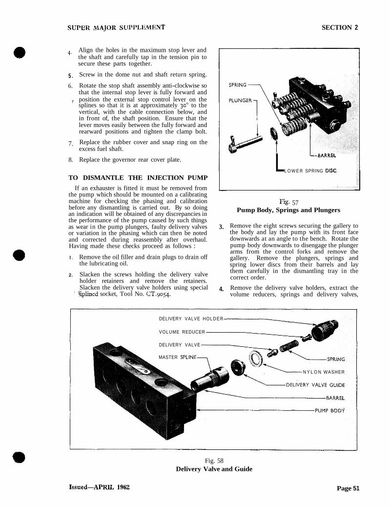
Fig. 57 Pump Body, Springs and Plungers
3. Remove the eight screws securing the gallery to the body and lay the pump with its front face downwards at an angle to the bench. Rotate the pump body downwards to disengage the plunger arms from the control forks and remove the gallery. Remove the plungers, springs and spring lower discs from their barrels and lay them carefully in the dismantling tray in the correct order.
4. Remove the delivery valve holders, extract the volume reducers, springs and delivery valves,
DELIVERY VALVE HOLDER
VOLUME REDUCER
DELIVERY VALVE
MASTER SPLINE
N Y L O N WASHER
Fig. 58 Delivery Valve and Guide
Page 51

SUPER MAJOR SUPPLEMENT SECTION 2
keeping each set of parts in the respective com- partment of the dismantling tray.
5. Lay the gallery on the bench, tap the barrels with a hide mallet to free them from the splines and lift out the delivery valve guides, sealing washers and barrels. It is essential that all the mated parts of each pump element should be kept pgether. On no account should parts such as plungers and barrels or delivery valves and guides be mixed as they are mated parts.
6. Remove the timing indicator, after releasing the fixing screws.
7. Remove the front inspection cover plate, remove the screws locating the cover plate retainers, rotate the retainers' through goo and withdraw them.
8. Remove the tappet assemblies from the body, keeping them in their respective positions with the pumping elements. If the tappets are to be dismantled ~ u s h out the roller vin and remove the double iollers. Extract the &clip to enable the phasing spacer to be withdrawn from the tappet body.
9. Remove the two steel " T " pieces from between the tappet bores.
10. Using Tool No. cT.9015 to hold the pump coupling flange, remove the flange securing nut and lockwasher.
11. Use Tool No. CT.goo4 to remove the flange whilst still holding the flange with Tool No. CT.9015. Remove the Woodruff key from the camshaft.
12. It is advisable to check the camshaft end-float at thists,tage so that the thickness of shim behind the cams'ifaft bearing inner races may be adjusted,
Fig. 60 Checking Camshaft End-float
i i necessary, wher; the time comes to rebuild. Use adaptor, Tool No. CT.go17-I, in conjunction with dial gauge, Tool No. CT.gor 7 , by screwing the adaptor onto the threaded end of the camshaft and measure the end-float in relation to the pump body.
13. Remove the proofmeter drive adaptor from the rear cover plate. Remove the screws securing the rear cover plate to the pump body and ease the cover plate from its location.
14. The rear bearing outer race can be removed from the cover plate by using Tool No. CT.go5o in the follow in^ manner. First remove the oil seal then assembli the collet of the tool from the inside of the plate, collapsing the spring loaded arms of the tool so that they pass through, and locate on the outside of, the bearing cup. Screw in and fully tighten the expander from the outside of the cover plate then press the assembly thus formed rearwards out of the cover plate. Mark the position of the control lever relative to the cross-shaft, slacken the clamp bolt securing the control lever to the cross-shaft and remove the control lever. Remove the special bolt and nut locating the governor spring on the cross- shaft, remove the " E " clip from one end of the cross-shaft and slide out the cross-shaft, taking care not to lose the locating washers, shims snd " 0 " rings fitted at each side of the shaft. Lift out the governor spring and rocking lever, disengaging the rocking lever from the thrust pad on the weight carrier and the control rod, if necessary, easing the camshaft slightly rear- wards from the housing.
17. Lift out the camshaft and governor mash as an assembly.
Removing Pump Coupling Flange 18. Slacken the A!len screws securing the control
Page 52

SUPER MAJOR SUPPLEMENT SECTION 2
-:it.
BEARING CUP
Fig. 61 Removing Rear Bearing Outer Track
forks to the control rod and slide out the control rod disengaging the forks as the rod is withdrawn.
19. Remove the ball and cage assemblies from the bearing inner races on the camshaft on which they are a light push fit.
If necessary, remove the bearing inner races, using a suitable press, universal taper plate, Tool No. 370, slave ring, Tool No. CT.9056 and adaptors, Tool No. GT.6085-IA. Use thrust &d T.6085-2 to protect the proofmeter drive
Fig. 62 Removing Front Bearing Inner Track
extension of the camshaft when removing the rear race. Note the thickness of shims fitted between each bearing track and the adjacent shoulder on the camshaft. These should be divided equally between either end of the shaft.
20. After removing the rear bearing inner race and oil slinger plate, the governor thrust pad and bearing assembly, together with the weight carrier assembly, can be removed from the camshaft. Straighten the locking tabs on the screws securing the governor backplate to the camshaft and remove the screws and backplate which is dowelled to the camshaft.
21. If the front bearing cup is to be removed from the pump body first extract the oil seal then use Tool No. cT.9050 in a similar manner to that detailed in operation 14 where the corresponding rear bearing cup is being removed from the rear cover plate. Locating the expander in the opposite end of the collet will assist in locating the collet behind the bearing.
22. If it is necessary to remove the pump control rod bushes it should be noted that the rear bush is held in position by a small pin which locates in a drilling 111 the pump body directly above the bush, and protrudes from the body just sufficiently to engage the wall of the bush. Before removing the bush the pin must be driven downwards through the locating hole in the bush and extracted through the bore. When replacing the bush it must be positioned with the pin hole facing upwards and in alignment with the d r i h g in rhe body. The pin must then be driven downwards through the drilling until its lower end locates in the wall of the bush. Care must be taken to see that the pin is not
TOOL Nt
CT 90%
Fig. 63 Removing Front Bearing Outer Track
Page 53
SUPER MAJOR SUPP1,EMENT SECTION 2
driven in to such an extent that it fouls the control rod.
When replacing the front bush the oil-way should be positioned so that it is within approxi- mately 15 of the bottom of the bore to prevent oil being trapped In the control rod end cover. The cover and retaining screw should be sealed to t ly cambox with a jointing compound, such as EM-4G-47, taking care not to allow the compound to enter the control rod bore.
TO REASSEMBLE THE INJECTION PUMP
I . Replace the bearing cups in the body and cover plate using Tool No CT.9051 by first assembling the cup to the tool, then locating this assembly on the inside of the bearing bore in the housing or cover plate. The washer and nut of the tool should then be assembled from the outside of the body or cover and a spanner used to t i ~ h t e n the nut and draw the bearing into posit~on. Replace the oil seals in the body and cover plate using a suitable size of drift.
2. Having regard to the camshaft end-float previously obtained, select the requisite thickness of shim for fitting between the camshaft and the camshaft bearing inner races. The total thickness of shim should be divided equally between the front and rear races.
Correct camshaft end-float is 0.002 to 0.005 in. (0.51 to 0.127 mm.) and shims are available in thickness of 0.004 and 0.008 in. (0.1 and 0.2 mm.).
3. Fit half the thickness of shims to the front end of the camshaft and assemble the bearing inner race using acsuitable press, universal taper plate,
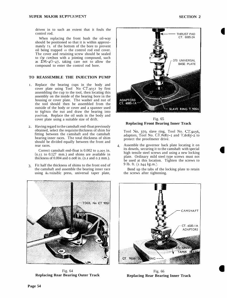
Fig. 64 Replacing Rear Bearing Outer Track
- THRUST PAD CT. 6085-2A
,- 370 UNIVERSAL BASE PLATE
Fig. 65 Replacing Front Bearing Inner Track
Tool No. 370, slave ring, Tool No. CT.9056, adaptors, Tool No. CT.6085-I and T.6085-2 to protect the proofmeter drive.
4. Assemble the governor back plate locating it on its dowels, securing it to the camshaft with special high tensile steel screws and using a new locking plate. Ordinary mild steel type screws must not be used at this location. Tighten the screws to 9 lb. ft. (1.244 kg.m.1.
Bend up the tabs of the locking plate to retain the screws after tightening.
Fig. 66 Replacing Rear Bearing Inner Track
Page 54
SUPER MAJOR SUPPLEMENT SECTION 2
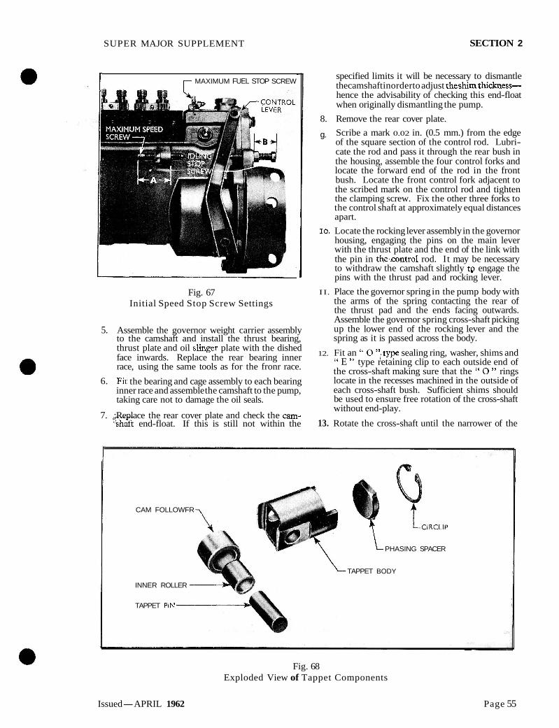
I r MAXIMUM FUEL STOP SCREW
Fig. 67 Initial Speed Stop Screw Settings
5. Assemble the governor weight carrier assembly to the camshaft and install the thrust bearing, thrust plate and oil slinger plate with the dished face inwards. Replace the rear bearing inner race, using the same tools as for the fronr race.
6. Fit the bearing and cage assembly to each bearing inner race and assemble the camshaft to the pump, taking care not to damage the oil seals.
7. ;Replace the rear cover plate and check the cam- 'sihaft end-float. If this is still not within the
specified limits it will be necessary to dismantle thecamshaft inorderto adjust theshim thickness- hence the advisability of checking this end-float when originally dismantling the pump.
8. Remove the rear cover plate.
g. Scribe a mark 0.02 in. (0.5 mm.) from the edge of the square section of the control rod. Lubri- cate the rod and pass it through the rear bush in the housing, assemble the four control forks and locate the forward end of the rod in the front bush. Locate the front control fork adjacent to the scribed mark on the control rod and tighten the clamping screw. Fix the other three forks to the control shaft at approximately equal distances apart.
10. Locate the rocking lever assembly in the governor housing, engaging the pins on the main lever with the thrust plate and the end of the link with the pin in the~.control rod. It may be necessary to withdraw the camshaft slightly tp engage the pins with the thrust pad and rocking lever.
I I. Place the governor spring in the pump body with the arms of the spring contacting the rear of the thrust pad and the ends facing outwards. Assemble the governor spring cross-shaft picking up the lower end of the rocking lever and the spring as it is passed across the body.
12. Fit an " 0 ",type sealing ring, washer, shims and " E " type retaining clip to each outside end of the cross-shaft making sure that the " 0 " rings locate in the recesses machined in the outside of each cross-shaft bush. Sufficient shims should be used to ensure free rotation of the cross-shaft without end-play.
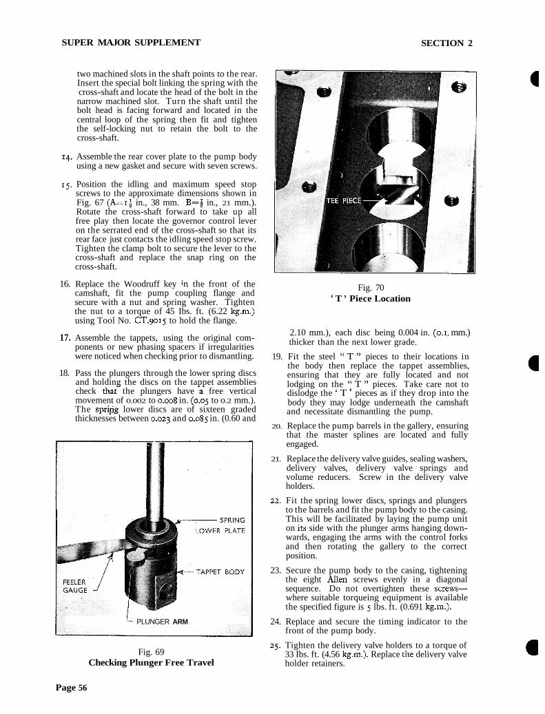
13. Rotate the cross-shaft until the narrower of the
CAM FOLLOWFR
INNER ROLLER
TAPPET Plb!
'L
-
PHASING SPACER
TAPPET BODY
Fig. 68 Exploded View of Tappet Components
Issued-APRIL 1962 Page 55
SUPER MAJOR SUPPLEMENT SECTION 2
two machined slots in the shaft points to the rear. Insert the special bolt linking the spring with the cross-shaft and locate the head of the bolt in the narrow machined slot. Turn the shaft until the bolt head is facing forward and located in the central loop of the spring then fit and tighten the self-locking nut to retain the bolt to the cross-shaft.
14. Assemble the rear cover plate to the pump body using a new gasket and secure with seven screws.
15. Position the idling and maximum speed stop screws to the approximate dimensions shown in Fig. 67 (A=I* in., 38 mm. B = i in., 21 mm.). Rotate the cross-shaft forward to take up all free play then locate the governor control lever on the serrated end of the cross-shaft so that its rear face just contacts the idling speed stop screw. Tighten the clamp bolt to secure the lever to the cross-shaft and replace the snap ring on the cross-shaft.
16. Replace the Woodruff key in the front of the camshaft, fit the pump coupling flange and secure with a nut and spring washer. Tighten the nut to a torque of 45 Ibs. ft. (6.22 kg.m.) using Tool No. CT.go15 to hold the flange.
17. Assemble the tappets, using the original com- ponents or new phasing spacers if irregularities were noticed when checking prior to dismantling.
18. Pass the plungers through the lower spring discs and holding the discs on the tappet assemblies check t h a t the plungers have a free vertical movement of 0.002 to 0.008 in. (0.05 to 0.2 mm.). The spsi,$g lower discs are of sixteen graded thicknesses between 0.023 and 0.085 in. (0.60 and
PLUNGER ARM
Fig. 69 Checking Plunger Free Travel
Fig. 70 ' T ' Piece Location
2.10 mm.), each disc being 0.004 in. (0.1, mm.) thicker than the next lower grade.
19. Fit the steel " T " pieces to their locations in the body then replace the tappet assemblies, ensuring that they are fully located and not lodging on the " T " pieces. Take care not to dislodge the ' T ' pieces as if they drop into the body they may lodge underneath the camshaft and necessitate dismantling the pump.
20. Replace the pump barrels in the gallery, ensuring that the master splines are located and fully engaged.
21. Replace the delivery valve guides, sealing washers, delivery valves, delivery valve springs and volume reducers. Screw in the delivery valve holders.
22. Fit the spring lower discs, springs and plungers to the barrels and fit the pump body to the casing. This will be facilitated by laying the pump unit on its side with the plunger arms hanging down- wards, engaging the arms with the control forks and then rotating the gallery to the correct position.
23. Secure the pump body to the casing, tightening the eight Allen screws evenly in a diagonal sequence. Do not overtighten these screws- where suitable torqueing equipment is available the specified figure is 5 lbs. ft. (0.691 kg.m.).
24. Replace and secure the timing indicator to the front of the pump body.
25. Tighten the delivery valve holders to a torque of 33 Ibs. ft. (4.56 kg.m.). Replace the delivery valve holder retainers.
Page 56
SUPER MAJOR SUPPLEMENT SECTION 2
26. Phase and calibrate the pump as previously described. If adjustment is made to the phasing spacers it will also be necessary to check and adjust the thickness of the spring lower discs to give the correct plunger free travel.
27. Replace the two inspection cover retainers turning each one through go0 to locate in the slots in the
? pump housing and to bring the notch in each retainer to the top.
28. Insert the hexagon headed locating screws and ensure that they locate in the notches in the retainer before fully tightening.
29. Place a new inspection cover plate gasket in the recess in the housing and assemble the plate, securing with the two k i n g screws to the retainers.
FITTING AND TJMING THE INJECTION PUMP
I. Turn the engine until the 21' marking on the flywheel coincides with the notch in the edge of the flywheel inspection aperture with No. I piston on the compression stroke.
2. Fit the pump to the engine ensuring that the timing mark on the pump timing plate coincides with the timing mark on the pump coupling and that there is 0.010 in. (0.02 mm.) end-float between fibre disc and coupling before tightening the coupling claw bolts. If it is necessary to adjust this clearance the flange securing bolt should be tightened before the two claw bolts.
When an exhauster is fitted it will be necessary to have the engine half of the coupling fully forward on the auxiliary drive shaft in order to
, I' assemble the exhauster and pump to the engine "" as a single unit. Having secured the exhauster
and pump to the engine move the engine half of the coupling rearwards to engage with the fibre disc, check the 0.010 in. (0.02 mm.) end-float of the disc, tighten the M e n screw to clamp the coupling to the auxiliary drive shaft and tighten the two claw bolts.
Connect the throttle operating rod to the governor control lever and check that full movement of the lever is possible when the throttle control is operated.
Connect the stop control cable to the stop control lever ensuring that there is a slight clearance between stop control button and the control panel when the stop control lever is fully forward.
Replace the pump leak-off pipe, reconnect the injector pipes and connect the fuel feed pipe to the pump ensuring that all unions and olives are free from dirt.
Reconnect the proofmeter cable to the rear of the pump camshaft (excepting where an exhmster is fitted).
Turn the fuel tap to the " ON " position and bleed the fuel system.
Fill the pump cambox with engine lubricating oil up to the level plug.
FUEL LIFT PUMP
The lift pump fitted to current tractors, and with the mechanical governor is of new design.
The component parts of the new pump are shown in Fig. 71 and whilst the basic operating principles are similar to those of the previous pump it will be noted t h a ~ the diaphragm and valves now work in a horizontal instead of a vertical plane.
COVER -I r PULSATOR r PUMP BODY SEAL RETAINER7 r PUMP BODY DIAPHRAGM OUTER HALF
1 RETURN I PULL ROD I I
Fig. 71 Exploded View of Fuel Lift Pump
Page 57

SUPER MAJOR SUPPLEMENT SECTION 2
Other changes include the introduction of a pulsator diaphragm, in addition to the pumping diaphragm, which damps out pressure fluctuation and the re-location of the inlet and outlet ports.
Stripping and assembly of the pump may be carried out in the following manner :-
I. Remove the screw securing the pump cover plate and liftzoff the cover and rubber pulsator diaphragm.
2. Mark the positions of the two halves of the pump, and the position of the diaphragm so that they can be reassembled in the same relative positions.
3. Remove the six screws securing the two halves of the pump together. If necessary, punch back the staking and remove the valves from the outer half.
4. Drive out the pin securing the hand priming lever and withdraw the lever. The diaphragm pull rod cannot be detached from the rocker lever until the priming lever is withdrawn.
5. Push down the diaphragm and disengage the pull rod, then lift out the diaphragm and spring.
6. Punch back the staking and remove the pull rod oil seal and washer.
7. If necessary, punch back the staking, tap out the pivot pin and withdraw the rocker lever assembly, taking care not to lose the small spring fitted between the rocker lever and the housing.
Reassemble the pump in the reverse order to that described above ensuring that the small spring is replaced in position between the rocker lever and the housing. The diaphragm must be fully stretched, by pressing in the rocker lever, before the screws securing the two halves of the body are tightened.
SPECIAL TOOLS
The number of special tools required in addition to the existing range of fuel injection equipment has been kept to a minimum consistent with satisfactory servicing.
Listed below are the essential and desirable tools which have been approved.
Essential Tools : CT.go5o Camshaft Bearing Cup Remover CT.905 I Camshaft Bearing Cup Replacer CT.9054 Delivery Valve Aolder Wrench CT.9056 Slave Ring
370 Universal Taper Plate
Desirable Tools : CT.9055 " T " Key for Hexagon Screws
The 370 Universal Taper Plate has been used previously for car and truck operations and Dealers already in possession of this item will require Slave Ring CT.9056 to enable existing CT.6085 adaptors to be used when removing and replacing the camshaft bearing inn^ races.
8
l' . Fuel Lift Pump
SPECIFICATION Type . . . . . . . . Diaphragm, with hand primer. Mechanically operaied by engine camshaft.
When exhauster is fitted pump is operated by injection pump camshaft Delivery pressure . . . . . . Less exhauster . . 2 to 34 Ib./sq. in. (0.141 to 0.218 kg./sq. cm.)
With exhauster . . 2# to 4$ Ib./sq. in. (0.193 to 0.299 kg./sq. cm.) Fuel Injection Pump
Type . . . . . . . . . . . . . . . . Enclosed camshaft with mechanical governor Plunger stroke, diameter and helix angle . . . . . . . . . . . . 7mm. X 7.5rnm..x 45' Camshaft rotation . . . . . . . . . . . . . . . . . . Clockwse from drlve end Cold starting device . . . . . . . . . . . . . . . . . . . . Excess fuel control Camshaft end-float . . . . . . . . . . . . . . 0.002 to 0.005 in. (0.05 to 0.127 mm.) Camshaft end-float shims . . . . . . . . 0.004 and 0.008 in. thick (0.1 and 0.2 mm. thick) Injection pump calibration (200 injections at 600 r.p.m.) . . . . . . . . . . 12.8 to 13.2 C.CS.
Phasing tolerance . . . . . . . . . . . . . . . . f I" (pump) between elements Stroke to close inlet port . . . . . . . . . . . . 0.095 to 0.102 in. (2.4 to 2.6 mm.) Plunger head clearance . . . . . . . . . . . . 0.039 to 0.059 in. (1.0 to 1.5 mm.) Plunger to spring lower plate clearance . . . . . . .. o.ooztoo,oo8in.(o.o~too.zomm.) Adjustment by spring lower plates graded in thickness from 0.023 to 0.085 in. (0.60 to 2.10 mm.) in steps
of 0.004 ins. (0.1 mm.) Tightening Torques
Delivery valve holders . . . . . . . . . . . . . . . . 33 lb. ft. (4.56 kg.m.) Coupling flange nut . . - . . . . . . . . . . . . . . . 45 lb. ft. (6.22 kg.m.) Governor backplate screws . . . . . . . . . . . . . . . . g lb. ft. (1.244 kg.m.) Pump body to cambox screws . . . . . . . . . . . . . . 5 lb. ft. (0.691 kg.m.) All other & A/F nuts and screws . . . . . . . . . . . . . . 5 lb. ft. (0.691 kg.m.) Control fork securing screws . . . . . . . . . . . . . . 2 lb. ft. (0.276 kg.m.)
Page 58
MAJOR POWER MAJOR
j SUPPLEMENT
SEPARATING THE TRACTOR TO SEPARATE THE ENGINE AND FRONT AXLE ASSEMBLY FROM THE FRONT
TRANSMISSION
Should it be necessary at any time to dismantle the Tractor in order to carry out repairs to the clutch or gearbox the following general procedure should be adopted.
1. Drain the cooling system through the two taps, one at the base of the radiator and the other on the left-hand side of the cylinder block beneath the generator.
2. Remove the primary air cleaner, vertical exhaust silencer (where fitted) and renlove the bonnet by unscrewing the two screws in the rear bracket and lifting the bonnet rearwards.
3. Disconnect the proofmeter drive cable from the drive gear assen~bly adjacent to the front of the fuel injection pump.
4. Disconnect the stop control cable at the stop lever on the fuel injection pump.
5. Remove the spring clip and disconnect the horizontal throttle control rod from the throttle relay cross-shaft at the right-hand side of the rear of the engine.
6. Turn the fuel tap to the " OFF " position and disconnect the fuel tank to fuel lift pump pipe at the fuel lift pump.
7. ' '!Disconnect the fuel injector leak-of pipe at the rear of the right-hand side of the cylinder head by removing the banjo union bolt, taking care not to loose the copper washer\ fitted at either side of the banjo union.
8. Disconnect the battery.
9. Disconnect the crankcase breather pipe at the valve rocker cover pipe.
10. Disconnect the air inlet hose from the air cleaner by unscrewing the hose clamp at the air cleaner end.
11. Discodnect the two wires from the starter relay switch and renlove the main feed cable from the terminal at the front end of the starter motor. Remove the split pin and clevis pin, and disconnect the starter operating rod at the starter motor end.
12. Disconnect the two wires from the generator and release the wiring loon1 from the clip on the generator bracket.
13. Disconnect the feed wire from the oil pressure warning light switch assembly.
14. Pull out the snap connector\ of the head- lamp wiring at the left-hand side of the radiator cowl and release the wires from the two clips
SECTION 3
on the side of the radiator and a further clip on the left-hand side of the engine front mounting plate.
15. Remove the temperature gauge bulb from the front of the cylinder head and release the capillary tube from the clip on the radiator brace rod. Position the capillary tube and the wiring loom clear of the front of the tractor.
16. Unscrew the two screws retaining the tool box to the tractor, and remove the tool box.
17. Disconnect the steering drag link from the drop arm by removing the split pun and unscrew- ing the securing nut. Force the tapered ball pin from the tapered' bore in the drop arm using a suitable ball joint separator.
18. If a horizontal exhaust is fitted, renlove the exhaust pipe, silencer and tail pipe con~plete, by removing the two nut5 and bolts and one nut at the exhaust manifold, the nut from the silencer bracket at the side member and the bolt securing the tail pipe bracket to the underside of the left- hand axle shaft housing.
19. Support the engine and tranmission, using the tractor dismantling stand (Tool No. Tr/NMD 27). Place the two rail sections of the stand under the tractor and position the engine and gearbox supports in their appropriate positions under the tractor. To ensure that the gearbox \upport i \ correctly positioned it will be necessary to disconnect the power take-off lever link at its front end.
If the tractor dismantling stand is not avail- able, place suitable supports under the front transm~ssion housing of the tractor and using a n~ovable overhead gantry or floor crane tit lifting tackle to the engine and take the weight of the engine. Two engine lifting plates (Tool No. CT.6003) are available, one for fitting to the fuel filter boss at the right-hand rear of the cylinder head (this entails removing the fuel filter and pipes) and the other under the two front left-hand side cylinder head retaining bolt\.
20. Insert suitable wooden wedges between the cast stops on the front axle centre beam and the front cross-member to prevent movement between the engine and the front axle assembly.
31. Remove the four bolts and spring washers from the rear of each side member, that secure the side members to the front transmission houSing.
32. Remove the fourteen bolts retaining the engine to the front transn~ission housing and with- draw the engine, radiator and front axle as an assembly, moving it forward until clear of the front transmission housing.
Page 1

MAJOR POWER MAJOR
SUPPLEMENT SECTION 3
TO RECONNECT THE ENGINE AND FRONT AXLE ASSEMBLY TO THE FRONT TRANSMISSION
1. Move the engine, radiator and front axle assenlbly toyards the front transmission housing, ensuring that the main shaft l~nes up with the clutch pressure plate. On tractors fitted with double clutches, the power take-off input and main drive shafts must be aligned with their resective discs in the double clutch assembly.
2. Replace the fourteen bolt5 and spring washer\ retaining the engine to the front transniiss~on housing. The proofmeter drive cable retaining clip fits under the head of the uppermo\t bolt on the nght-hand side of the tractor, and the wiring loom and capillary tube clip fits under the head of the top bolt on the left-hand side directly below the inner edge of the air cleaner. Replace the four bolt\ and spring washerb in each side men1 ber.
3. Remove the wooden wedges fitted between the front axle centre bean1 and the front cross- men1 ber.
4. Remove the tractor dismantling stand (Tool No. Tr/NMD 27) or the lifting tackle, supports and engine lifting plates.
5. Replace the tool box and secure with two bolts and flat washers.
6. Reconnect the steering drag link to the drop arm, tighten the nut securely and fit a new split pin. , $ I
1, i- 7. Refit the exhaust systenl by replacing the two nuts and bolts and the nut at the manifold, the nut and bolt securing the silencer bracket to the side member and the bolt securing the tail pipe bracket to the underside of the left-hand rear axle shaft housing.
8. Re-route the capillary tube under the exhaust manifold, replace the temperature gauge bulb in the front of the cylinder head, and refit the tube in the clip on the left-hand side of the radiator brace rod.
9. Reconnect the headlamp wiring at the snap connectors and replace it in the clip on the left- hand side of the engine front mounting plate and the two clips running up the side of the radiator.
10. Reconnect the oil pressure warning light switch feed wire to the oil pressure warning light switch assembly.
11. Reconnect the two leads to the generator and replace the wiring loom in the clip on the generator bracket.
12. Reconnect the starter operating rod, replace the clevis pin and fit a new split pin. Reconnect the starter motor main feed cable and relay switch wires.
13. Reconnect the air inlet hose to the air cleaner and tighten the hose clamp securely.
14. Reconnect the crankcase breather pipe to the connection at the rear of the valve rocker cover.
15. Reconnect the battery leads.
16. Reconnect the fuel injector leak-of pipe at the right-hand rear of the cylinder head ensuring that there is a copper wahher titted at either side of the banjo union, and refit the union bolt.
i7. Reconnect the fuel tank to fuel lift pump pipe at the lift punip, turn the fuel tap to the " O N" position and bleed the fuel systeni at the fuel filter and injection punip.
18. Reconnect the horizontal throttle control rod to the relay cross-shaft at the right-hand rear of the engine and replace the spring clip.
19. Operate the excess fuel device by pressing the knob o n the fuel injection pump, and re- connect the stop control cable to the stop lever so that there is approxin~ately : inch (6.4 mm.) free nlovenient of the control a.t the control panel.
20. Reconnect the proofmeter drive cable ensuring that the drive cable runs in a smooth curve and there are no kinks.
21. Reti l l the cooling systeni.
27. Replace the bonnet and refit the two screws securing the rear bracket to the fuel tank.
TO SEPARATE THE REAR AXLE FROM THE FRONT TRANSMISSION AND ENGINE
ASSEMBLY
1. Drain the rear axle oil from the drain plug in the hydraulic pump filter screen cover. To facilitate the flow of oil remove the rear w l e filler plug.
2. Remove the two nuts and internally-toothed lockwashers securing the rear number plate lamp cover to the lamp, and disconnect the main feed wire from the four-way snap connector in the lamp. Pull the wire from the rubber grommet and remove it from the wiring clips at the top of the hydraulic lift ram cylinder housing and the main gear change lever housing. Positiop the wire clear of the rear of the tractor.
3. Remove the four bolts and spring washers retaining the main gear change lever housing assembly and remove the assembly.
4. Remove the two bolts and spring washers holding the left-hand foot plate to the left-hand bull pinion housing, the three nuts, bolts, flat washers and spring washers securing the foot plate to the wing, and the three carriage bolts, nuts and spring washers holding the foot plate to the front bracket. Remove the foot plate and clutch pedal stop bracket.
Page 2

MAJOR SUPPLEMENT POWER MAJOR
SECTION 3
The two inner carriage bolts retain the clutch pedal stop bracket.
5. Remove the split pin and clevis pin and dis- connect the left-hand brake cable from the left- hand operating lever.
6. Remove the clutch pedal ;etracting spring and disconnect the clutch operating rod from the lower end of the clutch balance lever (split pin and clevis pin).
7. Remove the two bolts and spring washers retaining the right-hand foot plate to the bull pinion housing, the three bolts, nuts, flat washers and spring washers holding the foot plate to the wing, and the two carriage bolts, nuts and spring washers securing the foot plate to the front bracket. Remove the foot plate.
The two carriagc bolts also hold the brake pedal stop bracket.
8. Renlove the split pin and flat washer securing the brake pedal pawl control rod to the brake pedal pawl, and remove the brake pedal stop bracket complete with the brake pedal pawl.
9. Remove the right and left-hand brake pedal retracting springs and disconnect the right-hand brake cable (split pin and clevis pin).
10. Remove the split pin and collar securing the right-hand brake pedal to the brake cross-shaft and remove the pedal. Loosen the clamp bolt on the left-hand brake pedal and move the pedal to the end of the shaft to clear the front transmission housinglrear axle housing flange.
1 1 , ~ Remove the Woodruff key from the right- h a d end of the shaft and move the shaft towards the left-hand side of the tractor, until the left- hand brake operating lever is clear of the front transmission housinglrear axle housing flange.
12. Renlove the bolt and spring washer securing the exhaust tail pipe bracket to the left-hand rear axle shaft housing, slacken the clanip at the rear of the silencer, and renlove the tail pipe.
13. Fit a suitable jack under the rear axle housing to support its weight, and pmition the gearbox trolley of the tractor di\mantling 5tand (Tool No. Tr/NMD 27) on its rail under the front transmission housing. I t will be nece\\ary to disconnect the power take-off lever link at the front end to allow the rear gearbox support to be correctly located.
If the tractor dismantling stand i \ not available, support the engine and front transmi\\ion assembly on a suitable movable overhead gantry or floor crane.
14. Remove the fourteen nuts, bolts and spring washers securing the rear axle housing to the front transmission housing, and disconnect the engine and front transmission assembly from the rear axle.
TO RECONNECT THE FRONT TRANS- MISSION AND ENGINE ASSEMBLY TO
THE REAR AXLE
1. Fit a new gasket and reconnect the front trans- mission and engine assen~bly to the rear axle and replace the fourteen bolts, nuts and spring washers. The foot plate brackets tit under the lower two bolts on the vertical joint face at either side of the tractor.
The upper bolt on the right-hand side retains the brake pedal pawl control bracket.
2. Remove the tractor dismantling stand or lifting tackle.
3. Reconnect the exhaust tail pipe to the silencer assenihly, tighten the clamp and replace the bolt and spring washer securing the tail pipe bracket to the left-hand rear axle shaft hous~ng.
4. Push the left-hand brake operating lever back into position against the rear axle housing and replace the Woodruff key in the right-hand end of the brake cross-shaft.
5. Repohition the left-hand brake pedal and tighten the clamp bolt securely. Replace the right-hand brake pedal and retaining collar and becure in position with a split pin.
6. Reconnect the right-hand brake cable, replace the clevis pin and spl~t pin securely. Replace the right- and left-hand brake pedal retracting springs.
7. Reposition the brake pedal stop bracket and reconnect the brake pedal pawl control rod to the brake pedal pawl on the stop bracket. Replace the flat washer and split pin securely.
8. Ketit the right-hand foot plate with two bolts and spring washers to the bull pinion housing. three bolts, nuts, flat washers and spring washers to the wing (a flat washer is fitted either side under the bolt head and spring washer), and two carriage bolts, nuts and spring washers to the front bracket. The carriage bolts also retain the brake pedal stop bracket.
9. Reconnect the clutch operating rod to the clutch balance lever, replace the clevis pin and split pin securely. Replace the clutch pedal retracting spring.
10. Reconnect the left-hand brake cable to the left-hand brake operating lever, replace the clevis pin and split pin securely.
I I . Refit the left-hand foot plate with two bolts and spring washers to the bull pinion housing, three bolts, nuts, flat washers and spring washers to the wing (a flat washer is fitted under the bolt head and spring washer), and three carriage bolts, nuts and spring washers to the front bracket. The inner two carriage bolts also retain the clutch pedal stop bracket.

MAJOR POWER MAJOR SUPPLEMENT SECTION 3
l . Fit a new gasket and replace the main gear 14. Refill the rear axle with approximately 5, change lever housing. Secure in position with Imperial gallons (10.8 U.S. gallons or 41 litres) Four bolts and spring washers (one of the rear of oil (up to the " high" mark on the dipstick) lamp wiring loom clips fits under the rear right- of the correct grade as shown below. hand bolt).
T r n ~ p e r a ~ u r r Range S..4.1<. Viscosity N u n ~ h r 13. ~e loca t e the rear lamp wire in the wiring Above ?O°F(-7OC) 30 H.D.1 or W/30H.D. clips, pass it through the rubber grommet in the Below 30°F ( - 7°C) 30 H.D. \ rear nurnber?plate lamp cover and reconnect the wire to the four-way snap connector. Replace the number plate lamp cover and secure in position with two nuts and lockwashers.
Page 4