maxima steering system
TRANSCRIPT
7/30/2019 Maxima Steering System
http://slidepdf.com/reader/full/maxima-steering-system 1/32
STEERING SYSTEM
SECTION STCONTENTS
PRECAUTIONS ...............................................................2
Supplemental Restraint System (SRS) ″ AIR
BAG″ and ″ SEAT BELT PRE-TENSIONER″ ...............2
Precautions for Steering System.................................2
PREPARATION ...............................................................3
Special Service Tools ..................................................3
Commercial Service Tool.............................................4
NOISE, VIBRATION AND HARSHNESS (NVH)
TROUBLESHOOTING .....................................................5
NVH Troubleshooting Chart.........................................5
ON-VEHICLE SERVICE ..................................................6Checking Steering Wheel Play....................................6
Checking Neutral Position on Steering Wheel............6
PRE-CHECKING........................................................6
CHECKING ...............................................................6
Front Wheel Turning Angle..........................................6
Checking Gear Housing Movement ............................6
Checking and Adjusting Drive Belts ............................7
Checking Fluid Level ...................................................7
Checking Fluid Leakage..............................................7
Bleeding Hydraulic System..........................................7
Checking Steering Wheel Turning Force ....................8
Checking Hydraulic System.........................................9
STEERING WHEEL AND STEERING COLUMN .........10
Components...............................................................10
Removal and Installation ...........................................10
STEERING WHEEL .................................................10
STEERING COLUMN ...............................................11
Disassembly and Assembly.......................................13
Inspection...................................................................14
TILT MECHANISM ...................................................14
POWER STEERING GEAR AND LINKAGE ................15
Components...............................................................15
Removal and Installation ...........................................16
Disassembly...............................................................18
Inspection...................................................................19
BOOT .....................................................................19
RACK .....................................................................19
GEAR SUB-ASSEMBLY ...........................................19
GEAR HOUSING CYLINDER ....................................19TIE-ROD OUTER AND INNER SOCKETS..................19
Assembly ...................................................................19
Adjustment.................................................................23
POWER STEERING OIL PUMP....................................25
Components...............................................................25
Pre-disassembly Inspection.......................................25
Disassembly...............................................................26
Inspection...................................................................27
Assembly ...................................................................27
SERVICE DATA AND SPECIFICATIONS (SDS) .........29
General Specifications...............................................29
Steering Wheel ..........................................................29Steering Column ........................................................29
Steering Gear and Linkage .......................................30
Power Steering ..........................................................31

7/30/2019 Maxima Steering System
http://slidepdf.com/reader/full/maxima-steering-system 2/32
Supplemental Restraint System (SRS) “AIRBAG” and “SEAT BELT PRE-TENSIONER”
NFST0038
The Supplemental Restraint System such as “AIR BAG” and “SEAT BELT PRE-TENSIONER” used along witha seat belt, helps to reduce the risk or severity of injury to the driver and front passenger for certain types ofcollision. The SRS system composition which is available to NISSAN MODEL A33 is as follows (The compo-
sition varies according to the destination and optional equipment.):+ For a frontal collision
The Supplemental Restraint System consists of driver air bag module (located in the center of the steer-ing wheel), front passenger air bag module (located on the instrument panel on passenger side), seat beltpre-tensioners, a diagnosis sensor unit, warning lamp, wiring harness and spiral cable.
+ For a side collisionThe Supplemental Restraint System consists of front side air bag module (located in the outer side of frontseat), satellite sensor, diagnosis sensor unit (one of components of air bags for a frontal collision), wiringharness, warning lamp (one of components of air bags for a frontal collision).
Information necessary to service the system safely is included in the RS section of this Service Manual.
WARNING:+ To avoid rendering the SRS inoperative, which could increase the risk of personal injury or death
in the event of a collision which would result in air bag inflation, all maintenance should be per-formed by an authorized NISSAN dealer.
+ Improper maintenance, including incorrect removal and installation of the SRS, can lead to per-sonal injury caused by unintentional activation of the system. For removal of Spiral Cable and AirBag Module, see the RS section.
+ Do not use electrical test equipment on any circuit related to the SRS unless instructed to in thisService Manual. SRS wiring harnesses can be identified with yellow harness connector (and withyellow harness protector or yellow insulation tape before the harness connectors).
Precautions for Steering SystemNFST0003
+ Before disassembly, thoroughly clean the outside of the unit.
+ Disassembly should be done in a clean work area. It is important to prevent the internal parts frombecoming contaminated by dirt or other foreign matter.
+ Place disassembled parts in order, on a parts rack, for easier and proper assembly.
+ Use nylon cloths or paper towels to clean the parts; common shop rags can leave lint that mightinterfere with their operation.
+ Before inspection or reassembly, carefully clean all parts with a general purpose, non-flammablesolvent.
+ Before assembly, apply a coat of recommended power steering fluid* to hydraulic parts. Vaselinemay be applied to O-rings and seals. Do not use any grease.
+ Replace all gaskets, seals and O-rings. Avoid damaging O-rings, seals and gaskets during instal-lation. Perform functional tests whenever designated.*: Type DexronTM III or equivalent. Refer to MA-13, “Fluids and Lubricants”.
PRECAUTIONSSupplemental Restraint System (SRS) “AIR BAG” and “SEAT BELT PRE-TENSIONER”
ST-2

7/30/2019 Maxima Steering System
http://slidepdf.com/reader/full/maxima-steering-system 3/32
Special Service ToolsNFST0004
Tool number
Tool nameDescription
KV48100700
Torque adapter
NT169
Measuring pinion rotating torque
KV48102500
Pressure gauge adapter
NT542
Measuring oil pressure
ST27180001
Steering wheel puller
NT544
Removing steering wheel
HT72520000
Ball joint remover
NT546
Removing ball joint
a: 33 mm (1.30 in)
b: 50 mm (1.97 in)
r: R11.5 mm (0.453 in)
KV48103500
Pressure gauge
NT547
Measuring oil pressure
KV48104400
Rack seal ring reformer
NT550
Reforming teflon ring
a: 50 mm (1.97 in) dia.b: 36 mm (1.42 in) dia.
c: 100 mm (3.94 in)
ST3127S000
1 GG91030000
Torque wrench
2 HT62940000
Socket adapter
3 HT62900000
Socket adapterNT541
Measuring turning torque
PREPARATIONSpecial Service Tools
ST-3

7/30/2019 Maxima Steering System
http://slidepdf.com/reader/full/maxima-steering-system 4/32
Commercial Service ToolNFST0005
Tool number Description
Oil pump attachment
NT774
Disassembling and assembling oil pump
Unit: mm (in)
PREPARATIONCommercial Service Tool
ST-4

7/30/2019 Maxima Steering System
http://slidepdf.com/reader/full/maxima-steering-system 5/32
P o s s i b l e c a u s e an d
S U S P E C T E D
P A R T S
Fluid level
Air in hydraulic system
Tie-rod ball joint swinging force
Tie-rod ball joint rotating torque
Tie-rod ball joint end play
Steering gear fluid leakageSteering wheel play
Steering gear rack sliding force
Drive belt looseness
Improper steering wheel
Improper installation or looseness or tilt lock lever
Mounting rubber deterioration
Steering column deformation or damage
Improper installation or looseness of steering column
Steering linkage looseness
DRIVE SHAFT
AXLE
SUSPENSION
TIRES
ROAD WHEEL
BRAKES
S y m p t om
S T E E R I N G
N oi s e
×
×
×
×
×
×
×
×
×
×
×
×
×
×
×
S h ak e
×
×
×
×
×
×
×
×
×
V i b r a t i on
×
×
×
×
×
×
×
×
×
S h i mm y
×
×
×
×
×
×
×
×
×
J u d d er
×
×
×
×
×
×
×
×: A p pl i c a b l e
S T - 5

7/30/2019 Maxima Steering System
http://slidepdf.com/reader/full/maxima-steering-system 6/32
SST489B
Checking Steering Wheel PlayNFST0007
+ With wheels in a straight-ahead position, check steering wheelplay.
Steering wheel play:
35 mm (1.38 in) or less
+ If it is not within specification, check the following for loose orworn components.
Steering gear assembly
Steering column
Front suspension and axle
SST490BA
Checking Neutral Position on Steering WheelNFST0008
PRE-CHECKINGNFST0008S01
+ Make sure that wheel alignment is correct.
Wheel alignment:
Refer to SU-14, SDS.
+Verify that the steering gear is centered before removing thesteering wheel.
CHECKINGNFST0008S02
1. Check that the steering wheel is in the neutral position whendriving straight ahead.
2. If it is not in the neutral position, remove the steering wheel andreinstall it correctly.
3. If the neutral position is between two teeth, loosen tie-rod locknuts. Turn the tie-rods by the same amount in opposite direc-tions on both left and right sides.
SMA127
Front Wheel Turning AngleNFST0009
1. Rotate steering wheel all the way right and left; measure turn-ing angle.
Turning angle of full turns:
Refer to SU-14, SDS.
2. If it is not within specification, check rack stroke.
Rack stroke “S”:
Refer to SDS, ST-30.
SST849C
Checking Gear Housing MovementNFST0010
1. Check the movement of steering gear housing during station-ary steering on a dry paved surface.
+ Apply a force of 49 N (5 kg, 11 lb) to steering wheel to checkthe gear housing movement.Turn off ignition key while checking.
Movement of gear housing:
±2 mm (±0.08 in) or less
2. If movement exceeds the limit, replace mount insulator afterconfirming proper installation of gear housing clamps.
ON-VEHICLE SERVICEChecking Steering Wheel Play
ST-6

7/30/2019 Maxima Steering System
http://slidepdf.com/reader/full/maxima-steering-system 7/32
Checking and Adjusting Drive BeltsNFST0011
Refer to MA-15, “Checking Drive Belts”.
SST850C
Checking Fluid LevelNFST0012
Check fluid level, referring to the scale on reservoir tank.Use “HOT” range for fluid temperatures of 50 to 80°C (122 to176°F).Use “COLD” range for fluid temperatures of 0 to 30°C (32 to 86°F).
CAUTION:
+ Do not overfill.+ Recommended fluid is Type DexronTM III or equivalent.
Refer to MA-13, “Fluids and Lubricants”.
SST851C
Checking Fluid LeakageNFST0013
Check the lines for improper attachment and for leaks, cracks,damage, loose connections, chafing and deterioration.
1. Run engine between idle speed and 1,000 rpm.
Make sure temperature of fluid in oil tank rises to 60 to 80°C(140 to 176°F).
2. Turn steering wheel right-to-left several times.3. Hold steering wheel at each “lock” position for five seconds
and carefully check for fluid leakage.
CAUTION:Do not hold the steering wheel in a locked position for morethan 15 seconds.
4. If fluid leakage at connectors is noticed, loosen flare nut andthen retighten.
Do not overtighten connector as this can damage O-ring,washer and connector.
5. If fluid leakage from power steering pump is noticed, checkpower steering pump. Refer to ST-25.
6. Check rack boots for accumulation of power steering fluid.
Bleeding Hydraulic SystemNFST0014
1. Raise front end of vehicle until wheels are clear of the ground.
2. Add fluid into oil tank to specified level. Then quickly turn steer-ing wheel fully to right and left and lightly touch steering stop-pers.Repeat steering wheel operation until fluid level no longerdecreases.
3. Start engine.
Repeat step 2. above.+ Incomplete air bleeding will cause the following to occur. When
this happens, bleed air again.
ON-VEHICLE SERVICEChecking and Adjusting Drive Belts
ST-7

7/30/2019 Maxima Steering System
http://slidepdf.com/reader/full/maxima-steering-system 8/32
a) Air bubbles in reservoir tank
b) Clicking noise in oil pump
c) Excessive buzzing in oil pump
Fluid noise may occur in the valve or oil pump. This is commonwhen the vehicle is stationary or while turning the steering wheel
slowly. This does not affect the performance or durability of thesystem.
SST491B
SST090B
Checking Steering Wheel Turning ForceNFST0015
1. Park vehicle on a level, dry surface and set parking brake.
2. Start engine.
3. Bring power steering fluid up to adequate operating tempera-ture. [Make sure temperature of fluid is approximately 60 to80°C (140 to 176°F).]
Tires need to be inflated to normal pressure.
4. Check steering wheel turning force when steering wheel hasbeen turned 360°from the neutral position.
Steering wheel turning force:
39 N (4 kg, 9 lb) or less
5. If steering wheel turning force is out of specification, checkrack sliding force.
a. Disconnect steering column lower joint and knuckle arms fromthe gear.
b. Start and run engine at idle to make sure steering fluid hasreached normal operating temperature.
c. Pull tie-rod slowly to move it from neutral position to±
11.5 mm(±0.453 in) at speed of 3.5 mm (0.138 in)/s. Check that racksliding force is within specification.
Average rack sliding force:
216 - 284 N (22 - 29 kg, 49 - 64 lb)
Maximum force deviation:
98 N (10 kg, 22 lb)
d. Check sliding force outside the above range at rack speed of40 mm (1.75 in)/s.
Rack sliding force:
Not more than 294 N (30 kg, 66 lb)
Maximum force deviation:
147 N (15 kg, 33 lb)6. If rack sliding force is not within specification, overhaul steer-
ing gear assembly.
7. If rack sliding force is OK, inspect steering column. Refer toST-13.
ON-VEHICLE SERVICEBleeding Hydraulic System (Cont’d)
ST-8

7/30/2019 Maxima Steering System
http://slidepdf.com/reader/full/maxima-steering-system 9/32
SST834-H
Checking Hydraulic SystemNFST0016
Before starting, check belt tension, driving pulley and tire pressure.
1. Set Tool. Open shut-off valve. Then bleed air. Refer to “Bleed-ing Hydraulic System”, ST-7.
2. Run engine at idle speed or 1,000 rpm.
Make sure temperature of fluid in tank rises to 60 to 80°C (140to 176°F).
WARNING:Warm up engine with shut-off valve fully opened. If engine isstarted with shut-off valve closed, fluid pressure in oil pumpincreases to maximum. This will raise oil temperature abnor-mally.
3. Check pressure with steering wheel fully turned to left and rightpositions with engine idling at 1,000 rpm.
CAUTION:Do not hold the steering wheel in a locked position for morethan 15 seconds.
Oil pump maximum standard pressure:8,140 - 8,728 kPa (83 - 89 kg/cm2, 1,180 - 1,266 psi)
+ If pressure reaches maximum operating pressure, system isOK.
+ If pressure increases above maximum operating pressure,check power steering pump flow control valve. Refer to ST-25.
4. If power steering pressure is below the maximum operatingpressure, slowly close shut-off valve and check pressureagain.
CAUTION:Do not close shut-off valve for more than 15 seconds.
+ If pressure increases to maximum operating pressure, gear isdamaged. Refer to “Removal and Installation”, ST-16.
+ If pressure remains below maximum operating pressure, pumpis damaged. Refer to “Disassembly”, ST-26.
5. After checking hydraulic system, remove Tool and add fluid asnecessary. Then completely bleed air out of system. Refer toST-7.
ON-VEHICLE SERVICEChecking Hydraulic System
ST-9

7/30/2019 Maxima Steering System
http://slidepdf.com/reader/full/maxima-steering-system 10/32
ComponentsNFST0017
SST852C
1. Air bag module2. Damper
3. Steering wheel
4. Spiral cable
5. Column cover6. Combination switch
7. Steering column assembly
8. Boot9. Clip
10. Lower joint
CAUTION:+ The rotation of the spiral cable (SRS “Air bag” component
part) is limited. If the steering gear must be removed, setthe front wheels in the straight-ahead direction. Do notrotate the steering column while the steering gear isremoved.
+ Remove the steering wheel before removing the steering
lower joint to avoid damaging the SRS spiral cable.
SBF812E
Removal and InstallationNFST0018
STEERING WHEELNFST0018S01
+ Remove air bag module and spiral cable.Refer to RS-17, “Removal — Air Bag Module and SpiralCable”.
STEERING WHEEL AND STEERING COLUMNComponents
ST-10

7/30/2019 Maxima Steering System
http://slidepdf.com/reader/full/maxima-steering-system 11/32
SRS266
+ Align spiral cable correctly when installing steering wheel.
a) Set the front wheels in the straight-ahead position.
b) Make sure that the spiral cable is in the neutral position.The neutral position is detected by turning left 2.5 revolutionsfrom the right end position. Align the two marks ( ).
CAUTION:The spiral cable may snap due to steering operation if thecable is installed in an improper position.Also, with the steering linkage disconnected, the cable maysnap by turning the steering wheel beyond the limited numberof turns. (The spiral cable can be turned up to 2.5 turns fromthe neutral position to both the right and left.)
SST853CA
+ Remove damper for steering wheel.
+ Remove steering wheel with Tool.
SST329C
STEERING COLUMNNFST0018S02
+ Remove key interlock cable (A/T models).
SST800A
+ When installing steering column, fingertighten all lower bracketand clamp retaining bolts; then tighten them securely. Do notapply undue stress to steering column.
+ When attaching coupling joint, be sure tightening bolt facescutout portion.
STEERING WHEEL AND STEERING COLUMNRemoval and Installation (Cont’d)
ST-11

7/30/2019 Maxima Steering System
http://slidepdf.com/reader/full/maxima-steering-system 12/32
SST491C
+ Align slit of lower joint with projection on dust cover. Insert jointuntil surface A contacts surface B.
CAUTION:After installation, turn steering wheel to make sure it movessmoothly. Ensure the number of turns are the same from thestraight forward position to left and right locks. Be sure thatthe steering wheel is in a neutral position when drivingstraight ahead.
STEERING WHEEL AND STEERING COLUMNRemoval and Installation (Cont’d)
ST-12

7/30/2019 Maxima Steering System
http://slidepdf.com/reader/full/maxima-steering-system 13/32
Disassembly and Assembly=NFST0019
SST854CB
1. Combination switch2. Lock nut
3. Jacket tube assembly
4. Tilt lever
5. Tilt lever stopper
6. Steering column mounting bracket7. Spring
8. Adjust bolt
9. Adjust bolt stopper
10. Nut11. Column shaft assembly
12. Steering column lower cover
13. Lower joint
SST490C
+ When disassembling and assembling, unlock steering lockwith key.
+ Remove combination switch.
+ Install lock nut on steering column shaft and tighten the nut.
STEERING WHEEL AND STEERING COLUMNDisassembly and Assembly
ST-13
7/30/2019 Maxima Steering System
http://slidepdf.com/reader/full/maxima-steering-system 14/32
SST741A
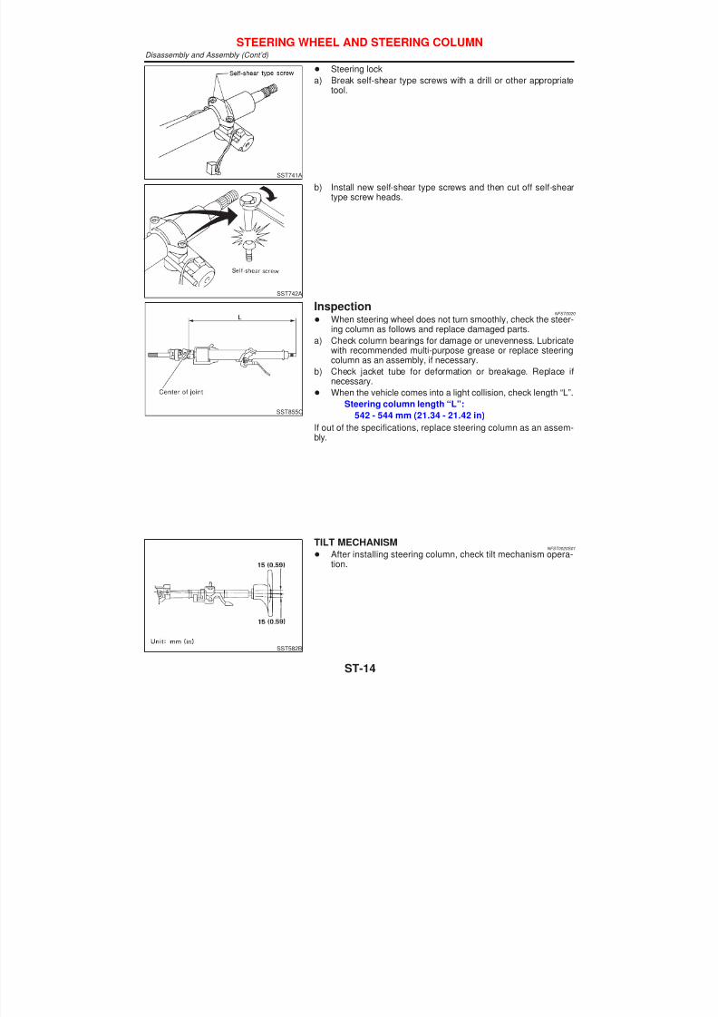
+ Steering lock
a) Break self-shear type screws with a drill or other appropriatetool.
SST742A
b) Install new self-shear type screws and then cut off self-sheartype screw heads.
SST855C
InspectionNFST0020
+ When steering wheel does not turn smoothly, check the steer-ing column as follows and replace damaged parts.
a) Check column bearings for damage or unevenness. Lubricatewith recommended multi-purpose grease or replace steeringcolumn as an assembly, if necessary.
b) Check jacket tube for deformation or breakage. Replace ifnecessary.
+ When the vehicle comes into a light collision, check length “L”.
Steering column length “L”:
542 - 544 mm (21.34 - 21.42 in)
If out of the specifications, replace steering column as an assem-bly.
SST582B
TILT MECHANISMNFST0020S01
+ After installing steering column, check tilt mechanism opera-tion.
STEERING WHEEL AND STEERING COLUMNDisassembly and Assembly (Cont’d)
ST-14

7/30/2019 Maxima Steering System
http://slidepdf.com/reader/full/maxima-steering-system 15/32
ComponentsNFST0021
SST856C
1. Rear cover cap
2. Gear sub-assembly
3. O-ring
4. Shim
5. Lock nut
6. Adjusting screw
7. Spring
8. Diaphragm spring
9. Washer
10. Spring seat
11. Retainer
12. Gear housing
13. Center bushing
14. Rack oil seal
15. Rack assembly
16. Rack seal ring
17. O-ring
18. Rack oil seal
19. End cover assembly
20. Boot band
21. Dust boot
22. Boot band
23. Spacer ring
24. Lock plate
25. Tie-rod inner socket
26. Tie-rod outer socket
27. Cotter pin
28. Gear housing tube
POWER STEERING GEAR AND LINKAGEComponents
ST-15

7/30/2019 Maxima Steering System
http://slidepdf.com/reader/full/maxima-steering-system 16/32
Removal and InstallationNFST0022
SST857C
1. Lower joint2. Hole cover
3. Insulator bracket
4. Clamp
5. Rear cover cap6. Gear and linkage assembly
7. Rack mounting insulator
8. Gear housing mounting bracket9. Cotter pin
10. Heat insulator
POWER STEERING GEAR AND LINKAGERemoval and Installation
ST-16
7/30/2019 Maxima Steering System
http://slidepdf.com/reader/full/maxima-steering-system 17/32
SFA455BD
SST858C
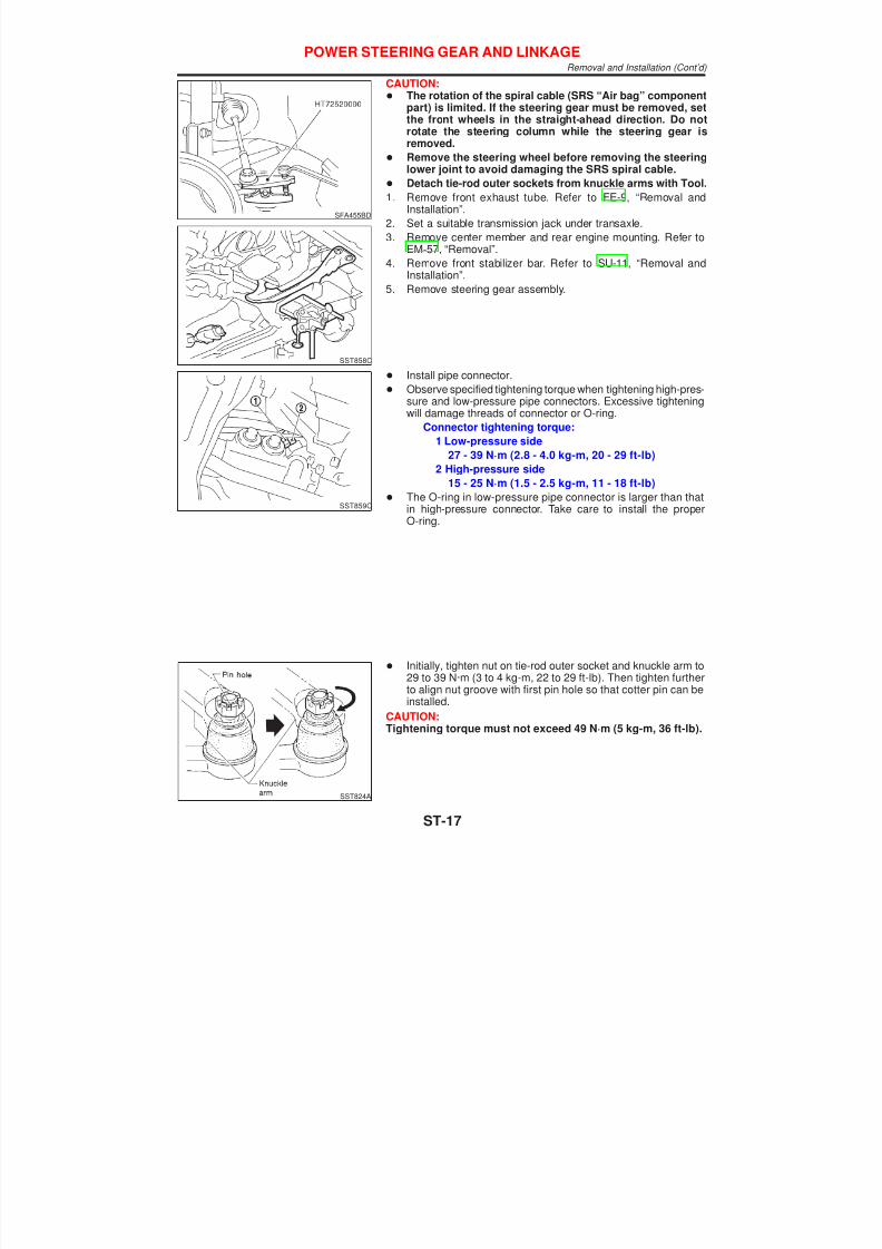
CAUTION:+ The rotation of the spiral cable (SRS “Air bag” component
part) is limited. If the steering gear must be removed, setthe front wheels in the straight-ahead direction. Do notrotate the steering column while the steering gear isremoved.
+ Remove the steering wheel before removing the steeringlower joint to avoid damaging the SRS spiral cable.
+ Detach tie-rod outer sockets from knuckle arms with Tool.
1. Remove front exhaust tube. Refer to FE-9, “Removal andInstallation”.
2. Set a suitable transmission jack under transaxle.
3. Remove center member and rear engine mounting. Refer toEM-57, “Removal”.
4. Remove front stabilizer bar. Refer to SU-11, “Removal andInstallation”.
5. Remove steering gear assembly.
SST859C
+ Install pipe connector.
+ Observe specified tightening torque when tightening high-pres-sure and low-pressure pipe connectors. Excessive tighteningwill damage threads of connector or O-ring.
Connector tightening torque:
1 Low-pressure side
27 - 39 N·m (2.8 - 4.0 kg-m, 20 - 29 ft-lb)
2 High-pressure side
15 - 25 N·m (1.5 - 2.5 kg-m, 11 - 18 ft-lb)
+ The O-ring in low-pressure pipe connector is larger than thatin high-pressure connector. Take care to install the properO-ring.
SST824A
+ Initially, tighten nut on tie-rod outer socket and knuckle arm to29 to 39 N·m (3 to 4 kg-m, 22 to 29 ft-lb). Then tighten furtherto align nut groove with first pin hole so that cotter pin can beinstalled.
CAUTION:Tightening torque must not exceed 49 N·m (5 kg-m, 36 ft-lb).
POWER STEERING GEAR AND LINKAGERemoval and Installation (Cont’d)
ST-17

7/30/2019 Maxima Steering System
http://slidepdf.com/reader/full/maxima-steering-system 18/32
SST860C
+ Before removing lower joint from gear, set gear in neutral(wheels in straight-ahead position). After removing lower joint,put matching mark on pinion shaft and pinion housing to recordneutral position.
+ To install, set left and right dust boots to equal deflection.Attach lower joint by aligning matching marks of pinion shaftand pinion housing.
SST861C
+ Tighten gear housing mounting bracket bolts in the ordershown.
SST862CA
DisassemblyNFST0023
1. Prior to disassembling, measure pinion rotating torque. Recordthe pinion rotating torque as a reference.
+ Before measuring, disconnect gear housing tube anddrain fluid.
+ Use soft jaws when holding steering gear housing. Handlegear housing carefully, as it is made of aluminum. Do notgrip cylinder in a vise.
2. Remove gear sub-assembly, O-ring and shim.
Gear sub-assembly cannot be disassembled. If it is faulty,replace with a new one.
SST051C
3. Remove tie-rod outer sockets and boots.
4. Loosen tie-rod inner socket by prying up staked portion, andremove socket and spacer.
5. Remove retainer.
6. Use a 2 to 2.5 mm (0.079 to 0.098 in) diameter drill to com-pletely remove staked portion of gear housing end.
SST052C
7. Remove end cover assembly with a suitable tool.
8. Draw out rack assembly.
9. Remove rack seal ring.
+ Using a heat gun, heat rack seal to approximately 40°C(104°F).
+ Remove rack seal ring.
Be careful not to damage rack.
POWER STEERING GEAR AND LINKAGERemoval and Installation (Cont’d)
ST-18

7/30/2019 Maxima Steering System
http://slidepdf.com/reader/full/maxima-steering-system 19/32
SST472A
10. Remove center bushing and rack oil seal using tape wrappedsocket and extension bar.
Do not scratch inner surfaces of pinion housing.
InspectionNFST0024
Thoroughly clean all parts in cleaning solvent or Genuine NISSANPSF II or equivalent. Blow dry with compressed air, if available.
BOOTNFST0024S01
+ Check condition of boot. If cracked excessively, replace it.
+ Check boots for accumulation of power steering fluid.RACK
NFST0024S02
Thoroughly examine rack gear. If damaged, cracked or worn,replace it.
GEAR SUB-ASSEMBLYNFST0024S03
+ Check pinion gear. If it is worn or damaged, replace as a gearsub-assembly.
+ Manually spin bearing. If torque variations or free play arenoted, replace as a gear sub-assembly.
GEAR HOUSING CYLINDERNFST0024S04
Check gear housing cylinder bore for scratches or other damage.Replace if necessary.
SST468C
TIE-ROD OUTER AND INNER SOCKETSNFST0024S05
+ Check ball joints for swinging force.
Tie-rod outer and inner ball joints swinging force “A”:
Refer to SDS, ST-30.
+ Check ball joint for rotating torque.
Tie-rod outer ball joint rotating torque “B”:
Refer to SDS, ST-30.
+ Check ball joints for axial end play.Tie-rod outer and inner ball joints axial end play “C”:
Refer to SDS, ST-30.
+ Check condition of dust cover. If cracked excessively, replaceouter tie-rod.
POWER STEERING GEAR AND LINKAGEDisassembly (Cont’d)
ST-19

7/30/2019 Maxima Steering System
http://slidepdf.com/reader/full/maxima-steering-system 20/32
SST083B
AssemblyNFST0025
1. Using a heat gun, heat new teflon rack seal ring to approxi-mately 40°C (104°F). Then place it onto rack.
SST885BC
2. Using Tool, compress rack seal ring securely onto rack.
Always insert Tool from the rack gear side.
SST201A
3. Insert new rack oil seal.
+ Place plastic film into rack oil seal to prevent damage byrack teeth.
+ Do not forget to remove plastic film after rack oil seal ispositioned properly.
+ Make sure lips of rack oil seal face each other.
SST863C
4. Install center bushing and rack oil seal with rack assembly.
SST321B
5. Insert rack oil seal and end cover assembly to rack. Thentighten end cover assembly.
POWER STEERING GEAR AND LINKAGEAssembly
ST-20

7/30/2019 Maxima Steering System
http://slidepdf.com/reader/full/maxima-steering-system 21/32
SST073B
6. Fasten end cover assembly to gear housing by staking.
SST086BA
7. Set rack gear in neutral position.
Rack stroke “S”:
Refer to SDS, ST-30.
SST864C
8. Install adjustment shims and O-rings to gear sub-assembly.
+ Install the same number of adjustment shims as before,regardless of whether or not gear sub-assembly is replaced.
+ Discard old O-rings; replace with new ones.
9. Tighten gear subassembly securing bolts to specified tighten-ing torque.
SST865C
10. Ensure that the rack is centered. Install rear cover cap so thatits protrusion is positioned as shown in figure.
SST087B
11. Install diaphragm spring into gear housing.
+ Always install retainer, spring washer and diaphragm spring inthat order.
+ Make sure convex end (painted white) of diaphragm springfaces outward when installing.
12. Install spring seat retainer spring and adjusting screw tempo-rarily.
POWER STEERING GEAR AND LINKAGEAssembly (Cont’d)
ST-21

7/30/2019 Maxima Steering System
http://slidepdf.com/reader/full/maxima-steering-system 22/32
SST866C
13. Install lock plate to rack.
a. Temporarily install spacer ring to rack.
Discard old spacer ring; replace with a new one.
b. Install lock plate to inner socket.
Discard old lock plate; replace with a new one.
c. Apply a coat of locking sealant to inner socket threads. Screwinner socket into rack and tighten to specified torque.
d. Clinch lock plate at rack groove location (at two points).
e. Install spacer ring to lock plate as shown in the Figure at left.
Be careful not to damage spacer ring during installation
SST867C
14. Tighten outer socket lock nut.
Tie-rod length “L”:
Refer to SDS, ST-30.
SST086BA
15. Measure rack stroke.
Rack stroke “S”:
Refer to SDS, ST-30.
SST967A
16. Before installing boot, coat the contact surfaces between bootand tie-rod with grease.
SST868C
17. Install boot bands.
+ Securely install boot band to boot groove and clinch the rootsection of the trapezoidal area.
+ Make sure that there is a clearance of 3.5 mm (0.138 in) or lessat the clinched section of the boot band. Refer to the Figure atleft.
POWER STEERING GEAR AND LINKAGEAssembly (Cont’d)
ST-22

7/30/2019 Maxima Steering System
http://slidepdf.com/reader/full/maxima-steering-system 23/32
SST869C
+ After installing gear in vehicle, make sure that the clinchedsection of boot band is positioned toward the rear of vehicle (toprevent interference with adjacent parts).
SST719C
AdjustmentNFST0026
Adjust pinion rotating torque as follows:
1. Set rack to the neutral position without fluid in the gear.
2. Coat the adjusting screw with locking sealant and screw it in.
3. Lightly tighten lock nut.
4. Tighten adjusting screw to a torque of 4.9 to 5.9 N·m (50 to 60kg-cm, 43 to 52 in-lb).
5. Loosen adjusting screw, then retighten it to 0.2 N·m (2 kg-cm,1.7 in-lb).
SST862CA
6. Move rack over its entire stroke several times.
7. Measure pinion rotating torque within the range of 180° fromneutral position.Stop the gear at the point of maximum torque.
8. Loosen adjusting screw, then retighten it to 4.9 N·m (50 kg-cm,43 in-lb).
9. Loosen adjusting screw by 60° to 80°.
SST713C
10. Prevent adjusting screw from turning, and tighten lock nut tospecified torque.
SST090B
11. Check rack sliding force on vehicle as follows:
a. Install steering gear onto vehicle, but do not connect tie-rod toknuckle arm.
b. Connect all piping and fill with steering fluid.
c. Start engine and bleed air completely.
d. Disconnect steering column lower joint from the gear.
e. Keep engine at idle and make sure steering fluid has reachednormal operating temperature.
f. Pull tie-rod slowly to move it from neutral position to ±11.5 mm(±0.453 in) at speed of 3.5 mm (0.138 in)/s. Check that racksliding force is within specification.
POWER STEERING GEAR AND LINKAGEAssembly (Cont’d)
ST-23

7/30/2019 Maxima Steering System
http://slidepdf.com/reader/full/maxima-steering-system 24/32
Average rack sliding force:
216 - 284 N (22 - 29 kg, 49 - 64 lb)
Maximum force deviation:
98 N (10 kg, 22 lb)
g. Check sliding force outside above range at rack speed of 40
mm (1.57 in)/s.Maximum rack sliding force:
294 N (30 kg, 66 lb)
Maximum force deviation:
147 N (15 kg, 33 lb)
+ If rack sliding force is not within specification, readjust byrepeating adjustment procedure from the beginning.
+ If rack sliding force is still out of specification afterreadjustment, gear assembly needs to be replaced.
POWER STEERING GEAR AND LINKAGEAdjustment (Cont’d)
ST-24
7/30/2019 Maxima Steering System
http://slidepdf.com/reader/full/maxima-steering-system 25/32
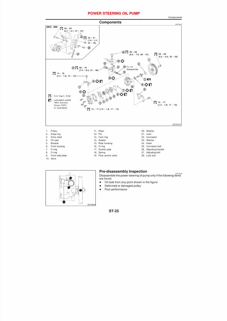
ComponentsNFST0027
SST870C
1. Pulley
2. Snap ring
3. Drive shaft
4. Oil seal
5. Bracket
6. Front housing
7. O-ring
8. O-ring
9. Front side plate
10. Vane
11. Rotor
12. Pin
13. Cam ring
14. Gasket
15. Rear housing
16. O-ring
17. Suction pipe
18. Spring
19. Flow control valve
20. Washer
21. Joint
22. Connector
23. Washer
24. Hose
25. Connector bolt
26. Adjusting bracket
27. Adjusting bolt
28. Lock bolt
SST984A
Pre-disassembly InspectionNFST0028
Disassemble the power steering oil pump only if the following itemsare found.
+ Oil leak from any point shown in the figure
+ Deformed or damaged pulley
+ Poor performance
POWER STEERING OIL PUMPComponents
ST-25
7/30/2019 Maxima Steering System
http://slidepdf.com/reader/full/maxima-steering-system 26/32
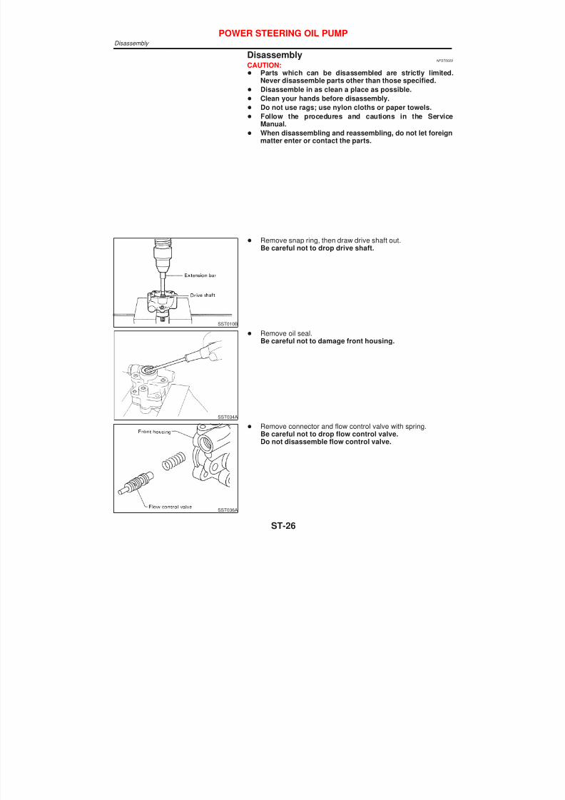
DisassemblyNFST0029
CAUTION:+ Parts which can be disassembled are strictly limited.
Never disassemble parts other than those specified.
+ Disassemble in as clean a place as possible.
+ Clean your hands before disassembly.+ Do not use rags; use nylon cloths or paper towels.
+ Follow the procedures and cautions in the ServiceManual.
+ When disassembling and reassembling, do not let foreignmatter enter or contact the parts.
SST010B
+ Remove snap ring, then draw drive shaft out.Be careful not to drop drive shaft.
SST034A
+ Remove oil seal.Be careful not to damage front housing.
SST036A
+ Remove connector and flow control valve with spring.Be careful not to drop flow control valve.Do not disassemble flow control valve.
POWER STEERING OIL PUMPDisassembly
ST-26
7/30/2019 Maxima Steering System
http://slidepdf.com/reader/full/maxima-steering-system 27/32
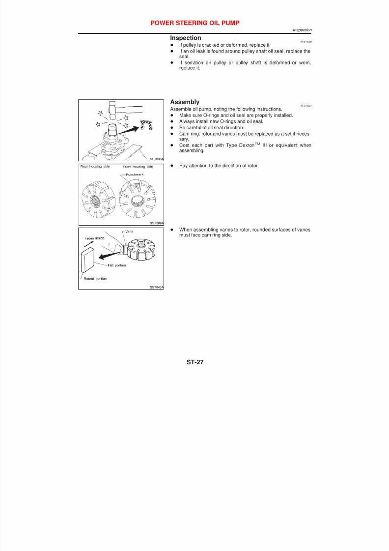
InspectionNFST0030
+ If pulley is cracked or deformed, replace it.
+ If an oil leak is found around pulley shaft oil seal, replace theseal.
+ If serration on pulley or pulley shaft is deformed or worn,
replace it.
SST038A
AssemblyNFST0031
Assemble oil pump, noting the following instructions.
+ Make sure O-rings and oil seal are properly installed.
+ Always install new O-rings and oil seal.
+ Be careful of oil seal direction.
+
Cam ring, rotor and vanes must be replaced as a set if neces-sary.
+ Coat each part with Type DexronTM III or equivalent whenassembling.
SST289A
+ Pay attention to the direction of rotor.
SST843A
+ When assembling vanes to rotor, rounded surfaces of vanesmust face cam ring side.
POWER STEERING OIL PUMPInspection
ST-27

7/30/2019 Maxima Steering System
http://slidepdf.com/reader/full/maxima-steering-system 28/32
SST472C
+ Insert pin 2 into pin groove 1 of front housing and front sideplate. Then install cam ring 3 as shown at left.
Cam ring:
D1 is less than D2.
POWER STEERING OIL PUMPAssembly (Cont’d)
ST-28

7/30/2019 Maxima Steering System
http://slidepdf.com/reader/full/maxima-steering-system 29/32
General SpecificationsNFST0032
Steering model Power steering
Steering gear type PR26AD
Steering overall gear ratio 16.6
Turns of steering wheel (Lock to lock) 2.9
Steering column type Collapsible, tilt
Steering WheelNFST0033
Steering wheel axial play mm (in) 0 (0)
Steering wheel play mm (in) 35 (1.38) or less
Movement of gear housing mm (in) ±2 (±0.08) or less
Steering ColumnNFST0034
Applied model All
Steering column length “L” mm (in) 542 - 544 (21.34 - 21.42)
SST855C
SERVICE DATA AND SPECIFICATIONS (SDS)General Specifications
ST-29

7/30/2019 Maxima Steering System
http://slidepdf.com/reader/full/maxima-steering-system 30/32
Steering Gear and LinkageNFST0035
Applied model All
Steering gear type PR26AD
Tie-rod outer ball joint
Swinging force at cotter pin hole: “A” N (kg, lb) 6.47 - 64.63 (0.66 - 6.59, 1.46 - 14.53)
Rotating torque: “B” N·m (kg-cm, in-lb) 0.29 - 2.94 (3.0 - 30.0, 2.6 - 26.0)
Axial end play: “C” mm (in) 0.4 (0.016) or less
Tie-rod inner ball jointSwinging force*: “A” N (kg, lb) 5.9 - 46.1 (0.58 - 4.65, 1.3 - 10.4)
Axial end play: “C” mm (in) 0.2 (0.008) or less
Tie-rod standard length “L” mm (in) 193.2 (7.606)
*: Measuring point [!: 172 mm (6.77 in)]
SST867C
Retainer adjustment
Adjusting screw
Initial tightening torque N·m (kg-cm, in-lb) 4.9 - 5.9 (50 - 60, 43 - 52)
Retightening torque after loosening N·m (kg-cm,
in-lb)0.2 (2, 1.7)
Tightening torque after gear has settled N·m
(kg-cm, in-lb)
4.9 - 5.9 (50 - 60, 43 - 52)
Returning angle degree 60° - 80°
Steering gear type PR26AD
Rack stroke “S” mm (in) 70.5 (2.776)
SST086BA
SERVICE DATA AND SPECIFICATIONS (SDS)Steering Gear and Linkage
ST-30

7/30/2019 Maxima Steering System
http://slidepdf.com/reader/full/maxima-steering-system 31/32
Power SteeringNFST0036
Applied model All
Steering gear type PR26AD
Rack sliding force N (kg, lb)
Under normal operating oil pres-
sure
Range within ±11.5 mm (±0.453 in)
from the neutral position at rackspeed of 3.5 mm (0.138 in)/s
Average force 216 - 284 (22 - 29, 49 - 64)
Maximum force deviation 98 (10, 22)
Except for the above rangeMaximum sliding force 294 (30, 66)
Maximum force deviation 147 (15, 33)
Steering wheel turning force
(Measured at one full turn from the neutral position) N (kg, lb)39 (4, 9) or less
Fluid capacity (Approximate) ! (Imp qt) 1.0 (7/8)
Oil pump maximum pressure kPa (bar, kg/cm2, psi)8,140 - 8,728 (81.4 - 87.3, 83 - 89,
1,180 - 1,266)
SERVICE DATA AND SPECIFICATIONS (SDS)Power Steering
ST-31

7/30/2019 Maxima Steering System
http://slidepdf.com/reader/full/maxima-steering-system 32/32
SERVICE DATA AND SPECIFICATIONS (SDS)Power Steering (Cont’d)