steering control system g steering stc a
TRANSCRIPT

STC-1
STEERING CONTROL SYSTEM
G STEERING
CONTENTS
C
D
E
F
H
I
J
K
L
M
SECTION STCA
B
STC
Revision: 2005 November 2006 Q45
STEERING CONTROL SYSTEM
WITHOUT REAR ACTIVE STEER
PRECAUTIONS .......................................................... 4Precautions for Supplemental Restraint System (SRS) “AIR BAG” and “SEAT BELT PRE-TEN-SIONER” .................................................................. 4Precautions .............................................................. 4
ELECTRICALLY CONTROLLED POWER STEER-ING SYSTEM .............................................................. 5
Power Steering Control Diagram .............................. 5Operation Principle ................................................... 5
DURING PARKING (WHEN TURNING THE STEERING WHEEL TO THE RIGHT.) .................. 5DURING HIGH-SPEED OPERATION ................... 6
System Description .................................................. 6DESCRIPTION ...................................................... 6POWER STEERING SOLENOID VALVE .............. 6CONTROL UNIT ................................................... 6
System Diagram ....................................................... 7COMPONENTS FUNCTION DESCRIPTION ....... 7
TROUBLE DIAGNOSIS .............................................. 8Fail-Safe Function .................................................... 8
FAIL-SAFE INPUT CONDITIONS ......................... 8How to Perform Trouble Diagnosis .......................... 8
BASIC CONCEPT ................................................. 8Component Parts Location ....................................... 9Wiring Diagram — EPS — ..................................... 10Active Damper Suspension Control Unit Input/Out-put Signal Reference Values .................................. 12
ACTIVE DAMPER SUSPENSION CONTROL UNIT INSPECTION TABLE ................................. 12
CONSULT-II Function (ACT D/SUS) ...................... 13FUNCTION .......................................................... 13CONSULT-II SETTING PROCEDURE ................ 13SELF-DIAG RESULT MODE .............................. 13DATA MONITOR MODE ..................................... 14
Self-Diagnostic Procedure ..................................... 14SELF-DIAGNOSTIC PROCEDURE (WITH CONSULT-II) ....................................................... 14SELF-DIAGNOSTIC PROCEDURE (WITHOUT
CONSULT-II) ....................................................... 14ERASE SELF-DIAGNOSIS ................................. 15
Inspections before Trouble Diagnosis .................... 16Trouble Diagnosis Chart for Symptoms .................. 16
TROUBLE DIAGNOSIS FOR SYSTEM .................... 17Power Supply Circuit .............................................. 17
ACTIVE DAMPER SUSPENSION CONTROL UNIT TERMINALS AND REFERENCE VALUE ... 17DIAGNOSTIC PROCEDURE .............................. 18
Vehicle Speed Sensor (VEHICLE SPEED SEN) .... 19CONSULT-II REFERENCE VALUE IN DATA MONITOR MODE ................................................ 19ACTIVE DAMPER SUSPENSION CONTROL UNIT TERMINALS AND REFERENCE VALUE ... 19DIAGNOSTIC PROCEDURE .............................. 20
Power Steering Solenoid Valve .............................. 21CONSULT-II REFERENCE VALUE IN DATA MONITOR MODE ................................................ 21ACTIVE DAMPER SUSPENSION CONTROL UNIT TERMINALS AND REFERENCE VALUE ... 21DIAGNOSTIC PROCEDURE .............................. 22
Engine Speed Signal .............................................. 24CONSULT-II REFERENCE VALUE IN DATA MONITOR MODE ................................................ 24ACTIVE DAMPER SUSPENSION CONTROL UNIT TERMINALS AND REFERENCE VALUE ... 24DIAGNOSTIC PROCEDURE .............................. 24
Component Inspection ............................................ 27POWER STEERING SOLENOID VALVE ............ 27
TROUBLE DIAGNOSIS FOR SYMPTOMS .............. 28Hard Steering When Fully Turning the Steering Wheel ..................................................................... 28
DIAGNOSTIC PROCEDURE .............................. 28Light Steering When Driving at a High Speed ........ 29
DIAGNOSTIC PROCEDURE .............................. 29CONTROL UNIT ....................................................... 30
Removal and Installation ........................................ 30REMOVAL ........................................................... 30INSTALLATION ................................................... 30

STC-2Revision: 2005 November 2006 Q45
WITH REAR ACTIVE STEER
PRECAUTIONS ......................................................... 31Precautions for Supplemental Restraint System (SRS) “AIR BAG” and “SEAT BELT PRE-TEN-SIONER” ................................................................. 31Precautions ............................................................. 31Precautions for RAS Actuator Assembly and Rear Wheel Steering Angle Sensor Replacement .......... 32
ELECTRICALLY CONTROLLED POWER STEER-ING ............................................................................ 33
Power Steering Control Diagram ............................ 33Operation Principle ................................................. 33
DURING PARKING (WHEN TURNING THE STEERING WHEEL TO THE RIGHT.) ................ 33DURING HIGH-SPEED OPERATION ................. 34
System Description ................................................. 34DESCRIPTION .................................................... 34POWER STEERING SOLENOID VALVE ............ 34CONTROL UNIT .................................................. 34
System Diagram ..................................................... 35COMPONENTS FUNCTION DESCRIPTION ...... 35
CAN Communication .............................................. 35SYSTEM DESCRIPTION .................................... 35
REAR ACTIVE STEER SYSTEM .............................. 36Power Steering Control Diagram ............................ 36Operation Principle ................................................. 36
OPERATION PRINCIPLE .................................... 36System Description ................................................. 37
DESCRIPTION .................................................... 37RAS ACTUATOR ASSEMBLY ............................. 37STEERING ANGLE SENSOR ............................. 37REAR WHEEL STEERING ANGLE SENSOR .... 37CONTROL UNIT .................................................. 38RAS WARNING LAMP ........................................ 38
System Diagram ..................................................... 38COMPONENTS FUNCTION DESCRIPTION ...... 39
CAN Communication .............................................. 39SYSTEM DESCRIPTION .................................... 39
TROUBLE DIAGNOSIS ............................................ 40Fail-Safe Function .................................................. 40How to Perform Trouble Diagnosis ......................... 40
BASIC CONCEPT ............................................... 40Component Parts Location ..................................... 41Circuit Diagram ....................................................... 42Wiring Diagram — RAS — ..................................... 43RAS Control Unit Input/Output Signal Reference Values ..................................................................... 47
RAS CONTROL UNIT INSPECTION TABLE ...... 47CONSULT-II Function (RAS/HICAS) ...................... 49
FUNCTION .......................................................... 49CONSULT-II SETTING PROCEDURE ................ 49SELF-DIAG RESULT MODE ............................... 49DATA MONITOR MODE ...................................... 51ACTIVE TEST MODE .......................................... 52RAS CONTROL UNIT PART NUMBER MODE ... 53
Self-Diagnostic Procedure ...................................... 53SELF-DIAGNOSTIC PROCEDURE (WITH CONSULT-II) ....................................................... 53
SELF-DIAGNOSTIC PROCEDURE (WITHOUT CONSULT-II) ........................................................53ERASE SELF-DIAGNOSIS ..................................54
Inspections before Trouble Diagnosis .....................55Trouble Diagnosis Chart for Symptoms ..................55
TROUBLE DIAGNOSIS FOR SYSTEM ....................56DTC C1900, C1901, C1905, C1906, C1907, C1908, C1922, C1927, C1928 CONTROL UNIT ....56
DIAGNOSTIC PROCEDURE ...............................56DTC C1925 AD CONVERTER ...............................56DTC C1902, C1903, C1904, C1910, C1913 MOTOR OUTPUT ...................................................57
CONSULT-II REFERENCE VALUE IN DATA MONITOR MODE ................................................57RAS CONTROL UNIT TERMINALS AND REF-ERENCE VALUE .................................................57DIAGNOSTIC PROCEDURE ...............................58
DTC C1909 CONTROL UNIT .................................60CONSULT-II REFERENCE VALUE IN DATA MONITOR MODE ................................................60RAS CONTROL UNIT TERMINALS AND REF-ERENCE VALUE .................................................60DIAGNOSTIC PROCEDURE ...............................60
DTC C1911, C1912 MOTOR VOLTAGE .................62CONSULT-II REFERENCE VALUE IN DATA MONITOR MODE ................................................62RAS CONTROL UNIT TERMINALS AND REF-ERENCE VALUE .................................................62DIAGNOSTIC PROCEDURE ...............................62
DTC C1914, C1915, C1916, C1917, C1918 RR ST ANGLE SENSOR ....................................................67
CONSULT-II REFERENCE VALUE IN DATA MONITOR MODE ................................................67RAS CONTROL UNIT TERMINALS AND REF-ERENCE VALUE .................................................67DIAGNOSTIC PROCEDURE ...............................68
DTC C1919 VEHICLE SPEED SEN .......................72DIAGNOSTIC PROCEDURE ...............................72
DTC C1920, C1923, C1924, C1926 STEERING ANGLE SEN ...........................................................72
DIAGNOSTIC PROCEDURE ...............................72DTC C1921 ENG REV SIGNAL ..............................73
DIAGNOSTIC PROCEDURE ...............................73DTC C1929 VDC ....................................................74
DIAGNOSTIC PROCEDURE ...............................74DTC U1000 CAN COMM ........................................75
DIAGNOSTIC PROCEDURE ...............................75DTC U1010 CONTROL UNIT (CAN) ......................75
DIAGNOSTIC PROCEDURE ...............................75RAS Actuator Assembly ..........................................76
DIAGNOSTIC PROCEDURE ...............................76Power Steering Solenoid Valve ...............................77
CONSULT-II REFERENCE VALUE IN DATA MONITOR MODE ................................................77RAS CONTROL UNIT TERMINALS AND REF-ERENCE VALUE .................................................77DIAGNOSTIC PROCEDURE ...............................78
Stop Lamp Switch ...................................................80CONSULT-II REFERENCE VALUE IN DATA

STC-3
C
D
E
F
H
I
J
K
L
M
A
B
STC
Revision: 2005 November 2006 Q45
MONITOR MODE ............................................... 80RAS CONTROL UNIT TERMINALS AND REF-ERENCE VALUE ................................................. 80DIAGNOSTIC PROCEDURE .............................. 80
Component Inspection ........................................... 82RAS MOTOR ...................................................... 82RAS MOTOR RELAY .......................................... 82NOISE SUPPRESSOR ....................................... 83REAR WHEEL STEERING ANGLE SENSOR .... 83POWER STEERING SOLENOID VALVE ............ 84STOP LAMP SWITCH ........................................ 84
TROUBLE DIAGNOSIS FOR SYMPTOMS .............. 85RAS Warning Lamp Does Not Turn ON for Approx. 1 Second When The Igniting Switch Is Turned to ON ... 85
DIAGNOSTIC PROCEDURE .............................. 85The Steering Force of Steering Wheel Is Not Changed Smoothly According to the Vehicle Speed ... 87
SYMPTOM: ......................................................... 87DIAGNOSTIC PROCEDURE .............................. 87
Hard Steering When Fully Turning the Steering
Wheel ..................................................................... 88DIAGNOSTIC PROCEDURE .............................. 88
Light Steering When Driving at a High Speed ........ 89DIAGNOSTIC PROCEDURE .............................. 89
CONTROL UNIT ....................................................... 90Removal and Installation ........................................ 90
REMOVAL ........................................................... 90INSTALLATION ................................................... 90
REAR ACTIVE STEER ............................................. 91Removal and Installation ........................................ 91
COMPONENTS ................................................... 91REMOVAL ........................................................... 91INSTALLATION ................................................... 91
Disassembly and Assembly .................................... 92COMPONENTS ................................................... 92DISASSEMBLY ................................................... 92INSPECTION AFTER DISASSEMBLY ................ 92ASSEMBLY ......................................................... 92ADJUSTMENT AFTER ASSEMBLING ............... 92
STC-4
[WITHOUT REAR ACTIVE STEER]PRECAUTIONS
Revision: 2005 November 2006 Q45
[WITHOUT REAR ACTIVE STEER]PRECAUTIONS PFP:00001
Precautions for Supplemental Restraint System (SRS) “AIR BAG” and “SEAT BELT PRE-TENSIONER” NGS0005P
The Supplemental Restraint System such as “AIR BAG” and “SEAT BELT PRE-TENSIONER”, used alongwith a front seat belt, helps to reduce the risk or severity of injury to the driver and front passenger for certaintypes of collision. This system includes seat belt switch inputs and dual stage front air bag modules. The SRSsystem uses the seat belt switches to determine the front air bag deployment, and may only deploy one frontair bag, depending on the severity of a collision and whether the front occupants are belted or unbelted.Information necessary to service the system safely is included in the SRS and SB section of this Service Man-ual.WARNING: To avoid rendering the SRS inoperative, which could increase the risk of personal injury or death
in the event of a collision which would result in air bag inflation, all maintenance must be per-formed by an authorized NISSAN/INFINITI dealer.
Improper maintenance, including incorrect removal and installation of the SRS, can lead to per-sonal injury caused by unintentional activation of the system. For removal of Spiral Cable and AirBag Module, see the SRS section.
Do not use electrical test equipment on any circuit related to the SRS unless instructed to in thisService Manual. SRS wiring harnesses can be identified by yellow and/or orange harnesses orharness connectors.
Precautions NGS0005Q
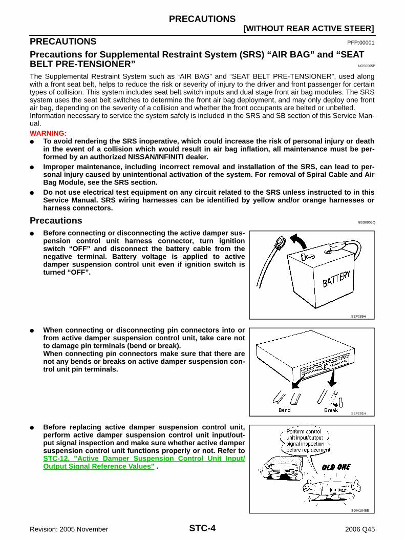
Before connecting or disconnecting the active damper sus-pension control unit harness connector, turn ignitionswitch “OFF” and disconnect the battery cable from thenegative terminal. Battery voltage is applied to activedamper suspension control unit even if ignition switch isturned “OFF”.
When connecting or disconnecting pin connectors into orfrom active damper suspension control unit, take care notto damage pin terminals (bend or break).When connecting pin connectors make sure that there arenot any bends or breaks on active damper suspension con-trol unit pin terminals.
Before replacing active damper suspension control unit,perform active damper suspension control unit input/out-put signal inspection and make sure whether active dampersuspension control unit functions properly or not. Refer toSTC-12, "Active Damper Suspension Control Unit Input/Output Signal Reference Values" .
SEF289H
SEF291H
SDIA1848E

ELECTRICALLY CONTROLLED POWER STEERING SYSTEM
STC-5
[WITHOUT REAR ACTIVE STEER]
C
D
E
F
H
I
J
K
L
M
A
B
STC
Revision: 2005 November 2006 Q45
ELECTRICALLY CONTROLLED POWER STEERING SYSTEM PFP:28500
Power Steering Control Diagram NGS000CQ
Operation Principle NGS000CV
DURING PARKING (WHEN TURNING THE STEERING WHEEL TO THE RIGHT.)
1. Power steering solenoid valve is closed while a vehicle is stopped.2. Pinion “1R”, “2R” and “3R” are closed depending on steering torque of steering wheel.3. Oil pressure “P” in the gear housing assembly is the sum of oil pressures occurred in “2R” and “3R”. This
results in a light steering force because of high pressure.
1. Speed sensor 2. Active damper suspension control unit
3. Power steering solenoid valve
4. Steering gear assembly 5. Gear housing assembly 6. Gear sub-assembly
7. Pinion 8. Power steering oil pump 9. Reservoir tank
SGIA1389E
SGIA1392E

STC-6
[WITHOUT REAR ACTIVE STEER]ELECTRICALLY CONTROLLED POWER STEERING SYSTEM
Revision: 2005 November 2006 Q45
DURING HIGH-SPEED OPERATION
1. Power steering solenoid valve is opened during high-speed operation.2. Pinion “1R”, “2R” and “3R” are closed depending on steering torque of steering wheel.3. Oil pressure “2R” does not occur because the power steering solenoid valve is on full throttle.4. Oil pressure “P” in the gear housing assembly includes only oil pressure occurred in “3R” and results in a
heavy steering force.
System Description NGS0004G
DESCRIPTION Electrically controlled power steering system is controlled by active damper suspension control unit. The system controls power steering solenoid valve by changing supply current to the power steering sole-
noid valve depending on vehicle speed.
POWER STEERING SOLENOID VALVE Vehicle speed sensing electronically controlled power steering
(that properly controls the steering force by the vehicle speed)has been adopted. When it is normal, it controls the powersteering solenoid valve according to the vehicle speed as shownin the figure and makes the steering force proper.
Power steering solenoid valve becomes full throttle when thepower steering solenoid valve voltage is 2.5 V, and totally-enclosed when the voltage is 5.5 V.
CONTROL UNIT The active damper suspension control unit (1) controls power
steering solenoid valve. Self-diagnosis can be done.
SGIA1393E
SST696CA
SGIA1394E

ELECTRICALLY CONTROLLED POWER STEERING SYSTEM
STC-7
[WITHOUT REAR ACTIVE STEER]
C
D
E
F
H
I
J
K
L
M
A
B
STC
Revision: 2005 November 2006 Q45
System Diagram NGS0005W
COMPONENTS FUNCTION DESCRIPTION
SGIA1395E
Component parts Function
Active damper suspension control unit Controls power steering solenoid valve (with fail-safe function).
Power steering solenoid valve Controls oil pressure in gear housing assembly.
Combination meter Combination meter sends vehicle speed signal to active damper suspension control unit.
ECMECM sends engine speed signal to active damper suspension control unit. (For fail-safe conditions)

STC-8
[WITHOUT REAR ACTIVE STEER]TROUBLE DIAGNOSIS
Revision: 2005 November 2006 Q45
TROUBLE DIAGNOSIS PFP:00004
Fail-Safe Function NGS00061
Fail-safe function starts under the vehicle conditions listed below.
FAIL-SAFE INPUT CONDITIONS
NOTE:When the engine is revved up to 1,500 rpm or more for at least 10 seconds with vehicle at standstill, the fail-safe function operates; however, this is not a matter of concern. The fail-safe function can be released by driv-ing vehicle of a speed of greater than 1.4 km/h (0.9 MPH) or by turning ignition switch from “OFF” to “ON”. The fail-safe function operates to regulate power steering sole-
noid valve operation in response to engine speed, thereby main-taining the required power steering force.
How to Perform Trouble Diagnosis NGS00062
BASIC CONCEPT To perform trouble diagnosis, it is the most important to have understanding about vehicle systems (con-
trol and mechanism) thoroughly. It is also important to clarify customer complaints before inspec-
tion.First of all, reproduce symptoms, and understand them fully.Ask customer about his/her complaints carefully. In some cases,it will be necessary to check symptoms by driving vehicle withcustomer.CAUTION:Customers are not professional. It is dangerous to make aneasy guess like “maybe the customer means that...,” or“maybe the customer mentions this symptom”.
It is essential to check symptoms right from the beginning inorder to repair malfunctions completely.For intermittent malfunctions, reproduce symptoms based oninterview with customer and past examples. Do not performinspection on ad hoc basis. Most intermittent malfunctions arecaused by poor contacts. In this case, it will be effective to shakesuspected harness or connector by hand. When repairing with-out any symptom diagnosis, you cannot judge if malfunctionshave actually been eliminated.
After completing diagnosis, always erase diagnostic memory.Refer to STC-15, "ERASE SELF-DIAGNOSIS" .
For intermittent malfunctions, move harness or harness connec-tor by hand. Then check for poor contact or reproduced open circuit.
Fail-safe input conditions Release conditions
No vehicle speed signal entered for at least 10 seconds while driving at an engine speed of greater than 1,500 rpm. A vehicle speed signal of greater than 1.4 km/h (0.9 MPH)
is entered.
Ignition switch is turned from “OFF” to “ON”. A vehicle speed signal of greater than 30 km/h (19 MPH) or abruptly drops below 2 km/h (1 MPH).
SST697CB
SEF233G
SEF234G

TROUBLE DIAGNOSIS
STC-9
[WITHOUT REAR ACTIVE STEER]
C
D
E
F
H
I
J
K
L
M
A
B
STC
Revision: 2005 November 2006 Q45
Component Parts Location NGS0005Y
SGIA1398E

STC-10
[WITHOUT REAR ACTIVE STEER]TROUBLE DIAGNOSIS
Revision: 2005 November 2006 Q45
Wiring Diagram — EPS — NGS00063
TGWM0075E

TROUBLE DIAGNOSIS
STC-11
[WITHOUT REAR ACTIVE STEER]
C
D
E
F
H
I
J
K
L
M
A
B
STC
Revision: 2005 November 2006 Q45
TGWM0076E

STC-12
[WITHOUT REAR ACTIVE STEER]TROUBLE DIAGNOSIS
Revision: 2005 November 2006 Q45
Active Damper Suspension Control Unit Input/Output Signal Reference ValuesNGS00064
ACTIVE DAMPER SUSPENSION CONTROL UNIT INSPECTION TABLESpecifications with CONSULT-II
Specifications Between Active Damper Suspension Control Unit Terminals
ACTIVE DAMPER SUSPENSION CONTROL UNIT CONNECTOR LAYOUT
Data are reference value and are measured between each terminal and ground.
Monitor item [Unit] Content Condition Display value
VHCL SPEED SE [km/h] or [mph]
Wheel speed
Vehicle stopped 0 km/h (0 MPH)
Vehicle running
CAUTION:Check air pressure of tire under standard condition.
Approximately equal to the indication on speedometer (Inside of ±10%)
POWER STR SOL [A]Monitored value of cur-rent at power steering solenoid valve
Vehicle speed: 0 km/h (0 MPH)(Engine is running)
Approx. 1.10 A
Vehicle speed: 100 km/h (62 MPH) Approx. 0.54 A
ENGINE SPEED [rpm] Engine speed
Engine stopped 0 rpm
Engine running(Engine speed: 400 rpm or more)
Approximately equal to the indication on tachometer
SGIA1399E
TerminalWire color
Item Condition Data (Approx.)
8 B Ground Always 0 V
10 GY Power supplyIgnition switch: ON Battery voltage
Ignition switch: OFF 0 V
12 W/G Engine speed
Engine speed: At idle(Warm-up condition)
Engine speed: Approx. 2,000 rpm(Warm-up condition)
14 BR/Y Data link connector (RX) — —
15 P Data link connector (TX) — —
PBIA3654J
PBIA3655J

TROUBLE DIAGNOSIS
STC-13
[WITHOUT REAR ACTIVE STEER]
C
D
E
F
H
I
J
K
L
M
A
B
STC
Revision: 2005 November 2006 Q45
CAUTION:When using circuit tester or oscilloscope to measure voltage for inspection, be sure not to extend forcibly any connector ter-minals.
CONSULT-II Function (ACT D/SUS) NGS00065
FUNCTIONCONSULT-II can display each diagnostic item using the diagnostic test modes shown following.
CONSULT-II SETTING PROCEDURERefer to GI-36, "CONSULT-II Start Procedure" .
SELF-DIAG RESULT MODEOperation Procedure1. Perform “CONSULT-II Start Procedure”. Refer to GI-36, "CONSULT-II Start Procedure" .2. With engine at idle, touch “SELF-DIAG RESULTS”.
Display shows malfunction experienced since the last erasing operation.NOTE:The details for “TIME” are as follows: “0”: Error currently detected with active damper suspension control unit. Except for “0”: Error detected in the past and memorized with active damper suspension control unit.
Detects frequency of driving after DTC occurs (frequency of turning ignition switch “ON/OFF”).
19 Y/GPower supply(Memory back-up)
Ignition switch: ONBattery voltage
Ignition switch: OFF
21 OR/L Power steering solenoid valve
Vehicle speed: 0 km/h (0 MPH)(Engine is running)
4.4 - 6.6 V
Vehicle speed: 100 km/h (62 MPH) 2.4 - 3.6 V
22 PU/W Vehicle speed
Vehicle speed: 40 km/h (25 MPH)
CAUTION:Check air pressure of tire under standard condition.
23 B Ground Always 0 V
24 B Ground Always 0 V
31 GY Power supplyIgnition switch: ON Battery voltage
Ignition switch: OFF 0 V
32 GY Power supplyIgnition switch: ON Battery voltage
Ignition switch: OFF 0 V
TerminalWire color
Item Condition Data (Approx.)
SEIA0775E
Diagnostic test mode FunctionReference
page
Self-diagnostic results Self-diagnostic results can be read and erased quickly. STC-13
Data monitor Input/Output data in the active damper suspension control unit can be read. STC-14

STC-14
[WITHOUT REAR ACTIVE STEER]TROUBLE DIAGNOSIS
Revision: 2005 November 2006 Q45
Display Item List
CAUTION:Active damper suspension system shall be checked when having indications that are not included in the item list.
How to Erase Self-diagnostic Results1. Perform applicable inspection of malfunctioning item and then repair or replace.2. Start engine and select “SELF-DIAG RESULTS” mode for “ACT D/SUS” with CONSULT-II.3. Touch “ERASE” on CONSULT-II screen to erase DTC memory.
CAUTION:If memory cannot be erased, perform applicable diagnosis.
DATA MONITOR MODEOperation Procedure1. Perform “CONSULT-II Start Procedure”. Refer to GI-36, "CONSULT-II Start Procedure" .2. Touch “DATA MONITOR”.3. Select from “SELECT MONITOR ITEM”, screen of data monitor mode is displayed.
NOTE:When malfunction is detected, CONSULT-II performs REAL-TIME DIAGNOSIS.Also, any malfunction detected while in this mode will be displayed in real time.
Display Item List
Self-Diagnostic Procedure NGS0006C
SELF-DIAGNOSTIC PROCEDURE (WITH CONSULT-II)Refer to STC-13, "SELF-DIAG RESULT MODE" .
SELF-DIAGNOSTIC PROCEDURE (WITHOUT CONSULT-II)DescriptionThe SPORT indicator lamp in the combination meter will flicker according to the self-diagnostic results. As forthe details of the SPORT indicator lamp flickering patterns, refer to STC-15, "Diagnostic Procedure" .
Items (CONSULT-II screen terms)
Diagnostic item is detected when... Check item
VEHICLE SPEED SEN Input signal does not change for some length of while driving.
Input signal change abruptly while driving.
STC-19, "Vehicle Speed Sensor (VEHICLE SPEED SEN)"
Monitored item (Unit) Remarks
VHCL SPEED SE [km/h] or [mph] Vehicle speed calculated by combination meter.
POWER STR SOL [A]Power steering solenoid controlling current that active damper suspension control unit outputs is displayed.
ENGINE SPEED [rpm] Engine speed calculated by ECM.
Voltage [V] The value measured by the voltage probe is displayed.
Frequency [Hz]
The value measured by the pulse probe is displayed.
DUTY-HI (high) [%]
DUTY-LOW (low) [%]
PLS WIDTH-HI [msec]
PLS WIDTH-LOW [msec]

TROUBLE DIAGNOSIS
STC-15
[WITHOUT REAR ACTIVE STEER]
C
D
E
F
H
I
J
K
L
M
A
B
STC
Revision: 2005 November 2006 Q45
Diagnostic Procedure1. Turn ignition switch to “OFF”.2. Start the engine.3. Quickly switch the active damper suspension select switch from “SPORT” to “AUTO”, and vice versa, at
least 5 times within 10 seconds immediately after the engine has started.4. Read the flickering of SPORT indicator lamp. Refer to STC-15, "Judgement Self-diagnosis" .
NOTE:When the SPORT indicator lamp flashes 1/4 Hz and continues repeating it, the system is normal.
5. Perform the following procedures to enter the corresponding signals. Turn steering wheel 180° in either direction from neutral. Depress brake pedal. Release brake pedal. Move the vehicle at least 5 m (16 ft) forward.
Judgement Self-diagnosisWhen a malfunction is detected, the malfunction route is indicated by flickering of the SPORT indicator lamp.
NOTE:When the SPORT indicator lamp flashes 1/4 Hz and continues repeating it, the system is normal.
CAUTION:Active damper suspension system shall be checked when patterns other than flickering pattern are output. Refer to SCS-24,"SELF-DIAG RESULT MODE" .
Disconnecting the Self-Diagnostic FunctionDisconnect the self-diagnostic function using one of the following three methods: Turn the ignition switch to “OFF”. Drive the vehicle at speeds greater than 30 km/h (19 MPH). Connect CONSULT-II.
ERASE SELF-DIAGNOSISClear self-diagnostic data and fail-safe data stored in memory as follows: While self-diagnosis is being performed, depress the brake pedal at least 5 times and shift the select
switch position at least 5 times. Pedal depression and switch shifting must be done within 10 seconds dur-ing self-diagnosis.
Flickering pattern Items Diagnostic item is detected when... Check item
11 Vehicle speed sensor Input signal does not change for some length of while driving.
Input signal change abruptly while driving.
STC-19, "Vehicle Speed Sensor (VEHICLE SPEED SEN)"
31 Engine speed signal When the engine speed is 360 rpm or less, while driving.STC-24, "Engine Speed Signal"
No flickeringActive damper suspen-sion select switch
Active damper suspension select switch circuit is shorted or open.
SCS-49, "Active Damper Suspen-sion Select Switch"
SGIA1402E
STC-16
[WITHOUT REAR ACTIVE STEER]TROUBLE DIAGNOSIS
Revision: 2005 November 2006 Q45
Inspections before Trouble Diagnosis NGS0006E
Inspect for power steering fluid leakage and check the power steering fluid level. Refer to PS-6, "POWERSTEERING FLUID" .
Power steering components (gears, oil pump, pipes, etc.) Are free from leakage, and that oil level is cor-rect.
Tires are inflated to specified pressure and are of specified size, and that steering wheel is a genuine Nis-san part.
Suspension utilizes the original design, and is free of modifications which increase vehicle weight. Wheel alignment is adjusted properly.
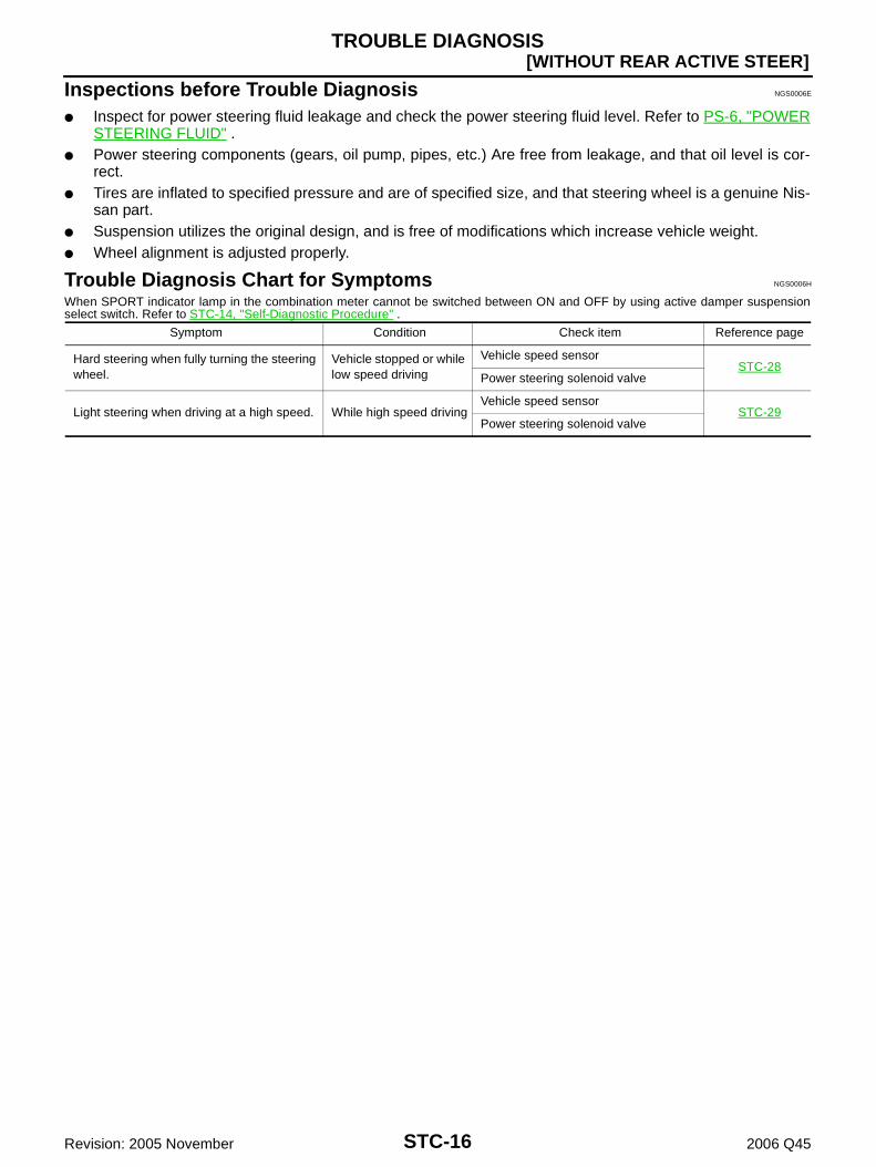
Trouble Diagnosis Chart for Symptoms NGS0006H
When SPORT indicator lamp in the combination meter cannot be switched between ON and OFF by using active damper suspensionselect switch. Refer to STC-14, "Self-Diagnostic Procedure" .
Symptom Condition Check item Reference page
Hard steering when fully turning the steering wheel.
Vehicle stopped or while low speed driving
Vehicle speed sensorSTC-28
Power steering solenoid valve
Light steering when driving at a high speed. While high speed drivingVehicle speed sensor
STC-29Power steering solenoid valve

TROUBLE DIAGNOSIS FOR SYSTEM
STC-17
[WITHOUT REAR ACTIVE STEER]
C
D
E
F
H
I
J
K
L
M
A
B
STC
Revision: 2005 November 2006 Q45
TROUBLE DIAGNOSIS FOR SYSTEM PFP:00000
Power Supply Circuit NGS0006B
ACTIVE DAMPER SUSPENSION CONTROL UNIT TERMINALS AND REFERENCE VALUEData are reference value and are measured between each terminal and ground.
CAUTION:When using a circuit tester to measure voltage for inspection, be sure not to extend forcibly any connector terminals.
TerminalWire color
Item Condition Data (Approx.)
8 B Ground Always 0 V
10 GY Power supplyIgnition switch: ON Battery voltage
Ignition switch: OFF 0 V
19 Y/GPower supply(Memory back-up)
Ignition switch: ONBattery voltage
Ignition switch: OFF
23 B Ground Always 0 V
24 B Ground Always 0 V
31 GY Power supplyIgnition switch: ON Battery voltage
Ignition switch: OFF 0 V
32 GY Power supplyIgnition switch: ON Battery voltage
Ignition switch: OFF 0 V

STC-18
[WITHOUT REAR ACTIVE STEER]TROUBLE DIAGNOSIS FOR SYSTEM
Revision: 2005 November 2006 Q45
DIAGNOSTIC PROCEDURE
1. CHECK POWER SUPPLY
1. Turn ignition switch “OFF”.2. Disconnect active damper suspension control unit harness connector.3. Check voltage between active damper suspension control unit
harness connector (A) terminals and ground.
4. Turn ignition switch “ON”. (Do not start engine.)5. Check voltage between active damper suspension control unit
harness connector (A) terminals and ground.
OK or NGOK >> GO TO 2.NG >> Check the following. If any items are damaged, repair or replace damaged parts.
10A fuses [No. 6, 7 located in the fuse block (J/B) No.1]. Refer to PG-2, "POWER SUPPLYROUTING" .
Harness for short or open between battery and active damper suspension control unit harnessconnector B37 terminal 19.
Harness for short or open between ignition switch and active damper suspension control unitharness connector B37 terminal 10, B38 terminals 31 and 32.
Battery and ignition switch. Refer to PG-2, "POWER SUPPLY ROUTING" .
2. CHECK GROUND CIRCUIT
1. Turn ignition switch “OFF”.2. Disconnect active damper suspension control unit harness connector.3. Check continuity between active damper suspension control unit
harness connector (A) B37 terminals 8, 23 and 24.
Also check harness for short to power.OK or NGOK >> INSPECTION ENDNG >> Repair open circuit or short to power in harness or con-
nectors.
Connector Terminal Voltage (Approx.)
B3710 - Ground 0 V
19 - Ground Battery voltage
B3831 - Ground
0 V32 - Ground
SGIA1414E
Connector Terminal Voltage (Approx.)
B3710 - Ground
Battery voltage19 - Ground
B3831 - Ground
32 - Ground
SGIA1420E
Continuity should exist.
SGIA1415E

TROUBLE DIAGNOSIS FOR SYSTEM
STC-19
[WITHOUT REAR ACTIVE STEER]
C
D
E
F
H
I
J
K
L
M
A
B
STC
Revision: 2005 November 2006 Q45
Vehicle Speed Sensor (VEHICLE SPEED SEN) NGS00066
Check the following if “VEHICLE SPEED SEN” is detected in self-diagnosis results with CONSULT-II or“flickering pattern for 11” is detected in self-diagnosis results without CONSULT-II.
CONSULT-II REFERENCE VALUE IN DATA MONITOR MODEData are reference value.
ACTIVE DAMPER SUSPENSION CONTROL UNIT TERMINALS AND REFERENCE VALUEData are reference value and are measured between each terminal and ground.
CAUTION:When using a oscilloscope to measure voltage for inspection, be sure not to extend forcibly any connector terminal.
Monitored item Content Condition Display value
VHCL SPEED SE [km/h] or [mph]
Wheel speed
Vehicle stopped 0 km/h (0 MPH)
Vehicle running
CAUTION:Check air pressure of tire under standard condition.
Approximately equal to the indica-tion on speedome-ter (Inside of ±10%)
TerminalWire color
Item Condition Data (Approx.)
22 PU/W Vehicle speed
Vehicle speed: 40 km/h (25 MPH)
CAUTION:Check air pressure of tire under standard condition.
SEIA0775E

STC-20
[WITHOUT REAR ACTIVE STEER]TROUBLE DIAGNOSIS FOR SYSTEM
Revision: 2005 November 2006 Q45
DIAGNOSTIC PROCEDURE
1. CHECK VEHICLE SPEED SENSOR
With CONSULT-II1. Start engine.2. Select “DATA MONITOR” mode for “ACT D/SUS” with CONSULT-II.3. Read out the value of “VHCL SPEED SE”.
Without CONSULT-II1. Start engine.2. Check signal between active damper suspension control unit
harness connector (A) terminal and ground with oscilloscope.
OK or NGOK >> GO TO 4.NG >> GO TO 2.
2. CHECK COMBINATION METER
1. Turn ignition switch “OFF”.2. Disconnect active damper suspension control unit harness connector.3. Check signal between combination meter harness connector
terminal (A) and ground with oscilloscope.
Also check harness for short to ground and short to power.OK or NGOK >> GO TO 3.NG >> Check combination meter. Refer to DI-16, "Trouble Diagnosis" .
Condition Display value
Vehicle stopped 0 km/h (0 MPH)
Vehicle running
CAUTION:Check air pressure of tire under standard condition.
Approximately equal to the indication on speedometer (Inside of ±10%)
SGIA1404E
Connector Terminal Condition Data (Approx.)
B37 22 -
Ground
Vehicle speed:40 km/h (25 MPH)
CAUTION:Check air pres-sure of tire under standard condi-tion.
SGIA1407ESEIA0775E
Connector Terminal Condition Data (Approx.)
M41 18 -
Ground
Vehicle speed:40 km/h (25 MPH)
CAUTION:Check air pres-sure of tire under standard condi-tion.
SGIA1408ESEIA0775E

TROUBLE DIAGNOSIS FOR SYSTEM
STC-21
[WITHOUT REAR ACTIVE STEER]
C
D
E
F
H
I
J
K
L
M
A
B
STC
Revision: 2005 November 2006 Q45
3. CHECK HARNESS BETWEEN ACTIVE DAMPER SUSPENSION CONTROL UNIT AND COMBINA-TION METER
1. Turn ignition switch “OFF”.2. Disconnect active damper suspension control unit harness connector and the combination meter harness
connector.3. Check continuity between active damper suspension control unit
harness connector (A) B37 terminal 22 and combination meterharness connector (B) M41 terminal 18.
Also check harness for short to ground and short to power.OK or NGOK >> GO TO 4.NG >> Repair or replace damaged parts.
4. CHECK ACTIVE DAMPER SUSPENSION CONTROL UNIT
Check active damper suspension control unit input/output signal. Refer to STC-12, "Active Damper Suspen-sion Control Unit Input/Output Signal Reference Values" .OK or NGOK >> GO TO 5.NG >> Check active damper suspension control unit pin terminals for damage or loose connection with
harness connector. If any items are damaged, repair or replace damaged parts.
5. CHECK DTC
Perform the self-diagnosis, after driving a vehicle for a while.OK or NGOK >> INSPECTION ENDNG >> Replace active damper suspension control unit. Refer to STC-30, "Removal and Installation" .
Power Steering Solenoid Valve NGS00069
CONSULT-II REFERENCE VALUE IN DATA MONITOR MODEData are reference value.
ACTIVE DAMPER SUSPENSION CONTROL UNIT TERMINALS AND REFERENCE VALUEData are reference value and are measured between each terminal and ground.
CAUTION:When using a circuit tester to measure voltage for inspection, be sure not to extend forcibly any connector terminal.
Continuity should exist.
SGIA1409E
Monitored item Content Condition Display value
POWER STR SOL [A]Monitored value of current at power steering solenoid valve
Vehicle speed: 0 km/h (0 MPH)(Engine is running)
Approx. 1.10 A
Vehicle speed: 100 km/h (62 MPH) Approx. 0.54 A
TerminalWire color
Item Condition Data (Approx.)
21 OR/L Power steering solenoid valve
Vehicle speed: 0 km/h (0 MPH)(Engine is running)
4.4 - 6.6 V
Vehicle speed: 100 km/h (62 MPH) 2.4 - 3.6 V

STC-22
[WITHOUT REAR ACTIVE STEER]TROUBLE DIAGNOSIS FOR SYSTEM
Revision: 2005 November 2006 Q45
DIAGNOSTIC PROCEDURE
1. CHECK POWER STEERING SOLENOID VALVE SIGNAL
With CONSULT-II1. Start engine.2. Select “DATA MONITOR” mode for “ACT D/SUS” with CONSULT-II.3. Read out the value of “POWER STR SOL”.
Without CONSULT-II1. Start engine.2. Check signal between active damper suspension control unit
harness connector (A) terminal and ground.
OK or NGOK >> GO TO 5.NG >> GO TO 2.
2. CHECK POWER STEERING SOLENOID VALVE GROUND CIRCUIT
1. Turn ignition switch “OFF”.2. Disconnect power steering solenoid valve harness connector.3. Check continuity between power steering solenoid valve har-
ness connector (A) F3 terminal 2 and ground.
Also check harness for short to power. OK or NG OK >> GO TO 3. NG >> Repair or replace damaged parts.
Condition Display value
Vehicle speed: 0 km/h (0 MPH)(Engine is running)
Approx. 1.10 A
Vehicle speed: 100 km/h (62 MPH) Approx. 0.54 A
SGIA1405E
Connector Terminal ConditionData
(Approx.)
B37 21 -
Ground
Vehicle speed: 0 km/h (0 MPH)(Engine is running)
4.4 - 6.6 V
Vehicle speed: 100 km/h (62 MPH) 2.4 - 3.6 V
SGIA1410E
Continuity should exist.
SGIA1411E

TROUBLE DIAGNOSIS FOR SYSTEM
STC-23
[WITHOUT REAR ACTIVE STEER]
C
D
E
F
H
I
J
K
L
M
A
B
STC
Revision: 2005 November 2006 Q45
3. CHECK POWER STEERING SOLENOID VALVE
1. Turn ignition switch “OFF”.2. Disconnect power steering solenoid valve harness connector.3. Check resistance between power steering solenoid valve con-
nector (A) terminals 1 and 2.
4. Check power steering solenoid valve connector (A) by listeningfor its operation sound while applying battery voltage to powersteering solenoid valve connector (A) terminals 1 (positive) and2 (negative).
OK or NG OK >> GO TO 4. NG >> Replace power steering solenoid valve. Refer to PS-17,
"Disassembly and Assembly" .
4. CHECK HARNESS BETWEEN ACTIVE DAMPER SUSPENSION CONTROL UNIT AND POWER STEERING SOLENOID VALVE
1. Turn ignition switch “OFF”.2. Disconnect active damper suspension control unit harness connector and power steering solenoid valve
harness connector.3. Check continuity between active damper suspension control unit
harness connector (A) B37 terminal 21 and power steering sole-noid valve harness connector (B) F3 terminal 1.
Also check harness for short to ground and short to power.OK or NGOK >> GO TO 5.NG >> Repair or replace damaged parts.
5. CHECK ACTIVE DAMPER SUSPENSION CONTROL UNIT
Check active damper suspension control unit input/output signal. Refer to STC-12, "Active Damper Suspen-sion Control Unit Input/Output Signal Reference Values" .OK or NGOK >> GO TO 6.NG >> Check active damper suspension control unit pin terminals for damage or loose connection with
harness connector. If any item is damaged, repair or replace damaged parts.
1 - 2 : Approx. 4 - 6 Ω
SGIA1412E
SGIA1419E
Continuity should exist.
SGIA1413E
STC-24
[WITHOUT REAR ACTIVE STEER]TROUBLE DIAGNOSIS FOR SYSTEM
Revision: 2005 November 2006 Q45
6. STEERING WHEEL TURNING FORCE INSPECTION
Check steering wheel turning force. Refer to PS-8, "STEERING WHEEL TURNING FORCE" .OK or NGOK >> INSPECTION ENDNG >> Check relief oil pressure of power steering oil pump and power steering gear. If any item is dam-
aged, repair or replace damaged parts. Refer to PS-26, "RELIEF OIL PRESSURE" (power steer-ing oil pump) and PS-17, "Disassembly and Assembly" (power steering gear).
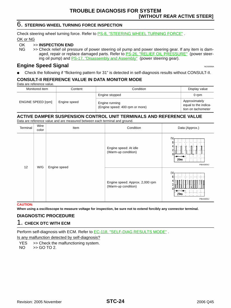
Engine Speed Signal NGS0006A
Check the following if “flickering pattern for 31” is detected in self-diagnosis results without CONSULT-II.
CONSULT-II REFERENCE VALUE IN DATA MONITOR MODEData are reference value.
ACTIVE DAMPER SUSPENSION CONTROL UNIT TERMINALS AND REFERENCE VALUEData are reference value and are measured between each terminal and ground.
CAUTION:When using a oscilloscope to measure voltage for inspection, be sure not to extend forcibly any connector terminal.
DIAGNOSTIC PROCEDURE
1. CHECK DTC WITH ECM
Perform self-diagnosis with ECM. Refer to EC-118, "SELF-DIAG RESULTS MODE" .Is any malfunction detected by self-diagnosis?YES >> Check the malfunctioning system.NO >> GO TO 2.
Monitored item Content Condition Display value
ENGINE SPEED [rpm] Engine speed
Engine stopped 0 rpm
Engine running(Engine speed: 400 rpm or more)
Approximately equal to the indica-tion on tachometer
TerminalWire color
Item Condition Data (Approx.)
12 W/G Engine speed
Engine speed: At idle(Warm-up condition)
Engine speed: Approx. 2,000 rpm(Warm-up condition)
PBIA3654J
PBIA3655J

TROUBLE DIAGNOSIS FOR SYSTEM
STC-25
[WITHOUT REAR ACTIVE STEER]
C
D
E
F
H
I
J
K
L
M
A
B
STC
Revision: 2005 November 2006 Q45
2. CHECK ENGINE SPEED SIGNAL
With CONSULT-II1. Start engine.2. Select “DATA MONITOR” mode for “ACT D/SUS” with CONSULT-II.3. Read out the value of “ENGINE SPEED”.
Without CONSULT-II1. Start engine.2. Check signal between active damper suspension control unit
harness connector (A) terminal and ground with oscilloscope.
Also check harness for short to ground and short to power.OK or NGYES >> GO TO 4.NO >> GO TO 3.
Condition Display value
Engine stopped 0 rpm
Engine running(Engine speed: 400 rpm or more)
Approximately equal to the indica-tion on tachometer
SEIA0779E
Connector Terminal Condition Data (Approx.)
B37 12 -
Ground
Engine speed: At idle(Warm-up condition)
Engine speed: Approx. 2,000 rpm(Warm-up condition)
SEIA0780EPBIA3654J
PBIA3655J

STC-26
[WITHOUT REAR ACTIVE STEER]TROUBLE DIAGNOSIS FOR SYSTEM
Revision: 2005 November 2006 Q45
3. CHECK HARNESS BETWEEN ECM AND ACTIVE DAMPER SUSPENSION CONTROL UNIT
1. Turn ignition switch “OFF”.2. Disconnect ECM harness connector and active damper suspension control unit harness connector.3. Check continuity between ECM harness connector (A) F101 ter-
minal 103 and active damper suspension control unit harnessconnector (B) B37 terminal 12.
Also check harness for short to ground and short to power.OK or NGOK >> GO TO 4.NG >> Repair or replace damaged parts.
4. CHECK ACTIVE DAMPER SUSPENSION CONTROL UNIT
Check active damper suspension control unit input/output signal. Refer to STC-12, "Active Damper Suspen-sion Control Unit Input/Output Signal Reference Values" .OK or NGOK >> GO TO 5.NG >> Check active damper suspension control unit pin terminals for damage or loose connection with
harness connector. If any items are damaged, repair or replace damaged parts.
5. CHECK DTC
Perform the self-diagnosis, after driving a vehicle for a while.OK or NGOK >> INSPECTION ENDNG >> Perform self-diagnosis with ECM again. Refer to EC-118, "SELF-DIAG RESULTS MODE" .
Continuity should exist.
SEIA0781E

TROUBLE DIAGNOSIS FOR SYSTEM
STC-27
[WITHOUT REAR ACTIVE STEER]
C
D
E
F
H
I
J
K
L
M
A
B
STC
Revision: 2005 November 2006 Q45
Component Inspection NGS000CT
POWER STEERING SOLENOID VALVE1. Turn ignition switch “OFF”.2. Disconnect power steering solenoid valve harness connector.3. Check resistance between power steering solenoid valve con-
nector (A) terminals 1 and 2.
4. Check power steering solenoid valve connector (A) by listeningfor its operation sound while applying battery voltage to powersteering solenoid valve connector (A) terminals 1 (positive) and2 (negative).
5. If NG, replace power steering solenoid valve.
1 - 2 : Approx. 4 - 6 Ω
SGIA1412E
SGIA1419E

STC-28
[WITHOUT REAR ACTIVE STEER]TROUBLE DIAGNOSIS FOR SYMPTOMS
Revision: 2005 November 2006 Q45
TROUBLE DIAGNOSIS FOR SYMPTOMS PFP:00007
Hard Steering When Fully Turning the Steering Wheel NGS0006F
DIAGNOSTIC PROCEDURE
1. CHECK SELF-DIAGNOSTIC RESULTS
Perform self-diagnosis. Refer to STC-13, "SELF-DIAG RESULT MODE" .Is any malfunction detected by self-diagnosis?YES >> Check the malfunctioning system.NO >> GO TO 2.
2. CHECK SYSTEM FOR VEHICLE SPEED SENSOR
Perform trouble diagnosis for vehicle speed sensor system. Refer to STC-19, "Vehicle Speed Sensor (VEHI-CLE SPEED SEN)" .OK or NGOK >> GO TO 3.NG >> Repair or replace damaged parts.
3. CHECK SYSTEM FOR POWER STEERING SOLENOID VALVE
Perform trouble diagnosis for power steering solenoid valve system. Refer to STC-21, "Power Steering Sole-noid Valve" .OK or NGOK >> GO TO 4.NG >> Repair or replace damaged parts.
4. CHECK ACTIVE DAMPER SUSPENSION CONTROL UNIT
Check active damper suspension control unit input/output signal. Refer to STC-12, "Active Damper Suspen-sion Control Unit Input/Output Signal Reference Values" .OK or NGOK >> GO TO 5.NG >> Check active damper suspension control unit pin terminals for damage or loose connection with
harness connector. If any items are damaged, repair or replace damaged parts.
5. CHECK SYMPTOM
Check again.OK or NGOK >> INSPECTION ENDNG >> Replace active damper suspension control unit. Refer to STC-30, "Removal and Installation" .
TROUBLE DIAGNOSIS FOR SYMPTOMS
STC-29
[WITHOUT REAR ACTIVE STEER]
C
D
E
F
H
I
J
K
L
M
A
B
STC
Revision: 2005 November 2006 Q45
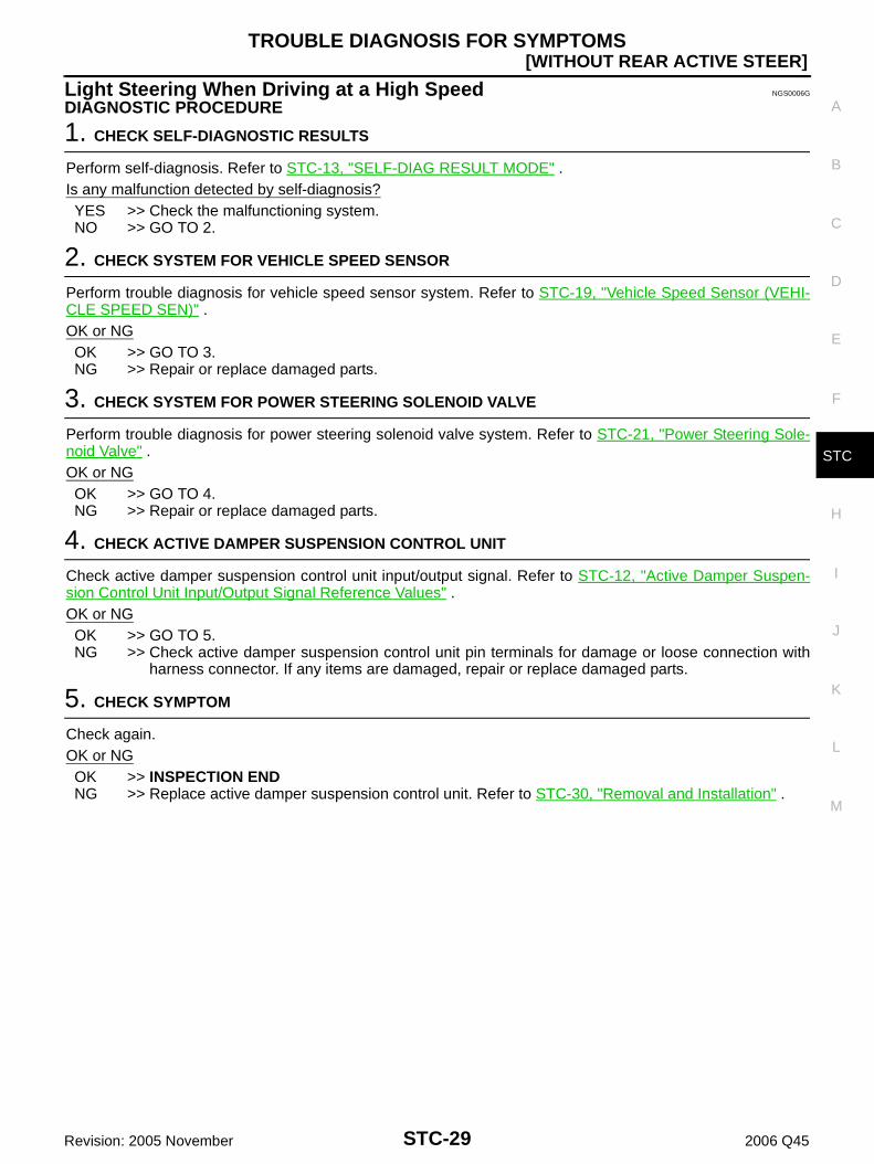
Light Steering When Driving at a High Speed NGS0006G
DIAGNOSTIC PROCEDURE
1. CHECK SELF-DIAGNOSTIC RESULTS
Perform self-diagnosis. Refer to STC-13, "SELF-DIAG RESULT MODE" .Is any malfunction detected by self-diagnosis?YES >> Check the malfunctioning system.NO >> GO TO 2.
2. CHECK SYSTEM FOR VEHICLE SPEED SENSOR
Perform trouble diagnosis for vehicle speed sensor system. Refer to STC-19, "Vehicle Speed Sensor (VEHI-CLE SPEED SEN)" .OK or NGOK >> GO TO 3.NG >> Repair or replace damaged parts.
3. CHECK SYSTEM FOR POWER STEERING SOLENOID VALVE
Perform trouble diagnosis for power steering solenoid valve system. Refer to STC-21, "Power Steering Sole-noid Valve" .OK or NGOK >> GO TO 4.NG >> Repair or replace damaged parts.
4. CHECK ACTIVE DAMPER SUSPENSION CONTROL UNIT
Check active damper suspension control unit input/output signal. Refer to STC-12, "Active Damper Suspen-sion Control Unit Input/Output Signal Reference Values" .OK or NGOK >> GO TO 5.NG >> Check active damper suspension control unit pin terminals for damage or loose connection with
harness connector. If any items are damaged, repair or replace damaged parts.
5. CHECK SYMPTOM
Check again.OK or NGOK >> INSPECTION ENDNG >> Replace active damper suspension control unit. Refer to STC-30, "Removal and Installation" .

STC-30
[WITHOUT REAR ACTIVE STEER]CONTROL UNIT
Revision: 2005 November 2006 Q45
CONTROL UNIT PFP:28400
Removal and Installation NGS0005R
REMOVAL1. Turn the ignition switch OFF and disconnect the battery cable from the negative terminal.2. Remove the trunk side finisher. Refer to EI-60, "Removal and Installation" .3. Disconnect the two active damper suspension control unit con-
nectors.4. Remove the active damper suspension control unit bolts.5. Remove the active damper suspension control unit (1).
INSTALLATIONNote the following, and installation is the reverse order of removal. When installing the active damper suspension control unit, tighten bolts to the specified torque.
SGIA1423E
Active damper suspension control unit bolts : 8.3 N·m (0.85 kg-m, 73 in-lb)

PRECAUTIONS
STC-31
[WITH REAR ACTIVE STEER]
C
D
E
F
H
I
J
K
L
M
A
B
STC
Revision: 2005 November 2006 Q45
[WITH REAR ACTIVE STEER]PRECAUTIONS PFP:00001
Precautions for Supplemental Restraint System (SRS) “AIR BAG” and “SEAT BELT PRE-TENSIONER” NGS0006I
The Supplemental Restraint System such as “AIR BAG” and “SEAT BELT PRE-TENSIONER”, used alongwith a front seat belt, helps to reduce the risk or severity of injury to the driver and front passenger for certaintypes of collision. This system includes seat belt switch inputs and dual stage front air bag modules. The SRSsystem uses the seat belt switches to determine the front air bag deployment, and may only deploy one frontair bag, depending on the severity of a collision and whether the front occupants are belted or unbelted.Information necessary to service the system safely is included in the SRS and SB section of this Service Man-ual.WARNING: To avoid rendering the SRS inoperative, which could increase the risk of personal injury or death
in the event of a collision which would result in air bag inflation, all maintenance must be per-formed by an authorized NISSAN/INFINITI dealer.
Improper maintenance, including incorrect removal and installation of the SRS, can lead to per-sonal injury caused by unintentional activation of the system. For removal of Spiral Cable and AirBag Module, see the SRS section.
Do not use electrical test equipment on any circuit related to the SRS unless instructed to in thisService Manual. SRS wiring harnesses can be identified by yellow and/or orange harnesses orharness connectors.
Precautions NGS0006J
Before connecting or disconnecting the RAS control unitharness connector, turn ignition switch “OFF” and discon-nect the battery cable from the negative terminal. Batteryvoltage is applied to RAS control unit even if ignition switchis turned “OFF”.
When connecting or disconnecting pin connectors into orfrom RAS control unit, take care not to damage pin termi-nals (bend or break).When connecting pin connectors make sure that there arenot any bends or breaks on RAS control unit pin terminals.
Before replacing RAS control unit, perform RAS controlunit input/output signal inspection and make sure whetherRAS control unit functions properly or not. Refer to STC-47,"RAS Control Unit Input/Output Signal Reference Values" .
SEF289H
SEF291H
SDIA1848E

STC-32
[WITH REAR ACTIVE STEER]PRECAUTIONS
Revision: 2005 November 2006 Q45
Precautions for RAS Actuator Assembly and Rear Wheel Steering Angle Sensor Replacement NGS000CW
When removing the RAS motor or rear wheel steering angle sensor from the RAS actuator assembly, performneutral position adjustment of RAS actuator assembly. Refer to STC-92, "Neutral Position" .

ELECTRICALLY CONTROLLED POWER STEERING
STC-33
[WITH REAR ACTIVE STEER]
C
D
E
F
H
I
J
K
L
M
A
B
STC
Revision: 2005 November 2006 Q45
ELECTRICALLY CONTROLLED POWER STEERING PFP:49810
Power Steering Control Diagram NGS000CR
Operation Principle NGS000CX
DURING PARKING (WHEN TURNING THE STEERING WHEEL TO THE RIGHT.)
1. Power steering solenoid valve is closed while a vehicle is stopped.2. Pinion “1R”, “2R” and “3R” are closed depending on steering torque of steering wheel.3. Oil pressure “P” in the gear housing assembly is the sum of oil pressures occurred in “2R” and “3R”. This
results in a light steering force because of high pressure.
1. Speed sensor 2. RAS control unit 3. Power steering solenoid valve
4. Steering gear assembly 5. Gear housing assembly 6. Gear sub-assembly
7. Pinion 8. Power steering oil pump 9. Reservoir tank
SGIA1389E
SGIA1583E

STC-34
[WITH REAR ACTIVE STEER]ELECTRICALLY CONTROLLED POWER STEERING
Revision: 2005 November 2006 Q45
DURING HIGH-SPEED OPERATION
1. Power steering solenoid valve is opened during high-speed operation.2. Pinion “1R”, “2R” and “3R” are closed depending on steering torque of steering wheel.3. Oil pressure “2R” does not occur because the power steering solenoid valve is on full throttle.4. Oil pressure “P” in the gear housing assembly includes only oil pressure occurred in “3R” and results in a
heavy steering force.
System Description NGS000CN
DESCRIPTION Electrically controlled power steering system is controlled by RAS control unit. The system controls power steering solenoid valve by changing supply current to the power steering sole-
noid valve depending on vehicle speed.
POWER STEERING SOLENOID VALVE Vehicle speed sensing electronically controlled power steering
(that properly controls the steering force by the vehicle speed)has been adopted. When it is normal, it controls the powersteering solenoid valve according to the vehicle speed as shownin the figure and makes the steering force proper.
Power steering solenoid valve becomes full throttle when thepower steering solenoid valve voltage is 2.5 V, and totally-enclosed when the voltage is 5.5 V.
CONTROL UNITThe RAS control unit (1) controls power steering solenoid valve.
SGIA1584E
SST696CA
SGIA1444E

ELECTRICALLY CONTROLLED POWER STEERING
STC-35
[WITH REAR ACTIVE STEER]
C
D
E
F
H
I
J
K
L
M
A
B
STC
Revision: 2005 November 2006 Q45
System Diagram NGS000CO
COMPONENTS FUNCTION DESCRIPTION
CAN Communication NGS000CP
SYSTEM DESCRIPTION CAN (Controller Area Network) is a serial communication line for real time application. It is an on-vehicle mul-tiplex communication line with high data communication speed and excellent error detection ability. Many elec-tronic control units are equipped onto a vehicle, and each control unit shares information and links with othercontrol units during operation (not independent). In CAN communication, control units are connected with 2communication lines (CAN-H line, CAN-L line) allowing a high rate of information transmission with less wiring.Each control unit transmits/receives data but selectively reads required data only.For details, refer to LAN-35, "CAN COMMUNICATION" .
SGIA1446E
Component parts Function
RAS control unit Controls power steering solenoid valve (with fail-safe function).
Power steering solenoid valve Controls oil pressure in gear housing assembly.
VDC/TCS/ABS control unit Transmits vehicle speed signal via CAN communication to RAS control unit. (For fail-safe conditions)
ECM Transmits engine speed signal via CAN communication to RAS control unit.

STC-36
[WITH REAR ACTIVE STEER]REAR ACTIVE STEER SYSTEM
Revision: 2005 November 2006 Q45
REAR ACTIVE STEER SYSTEM PFP:28505
Power Steering Control Diagram NGS0006Z
Operation Principle NGS000CY
OPERATION PRINCIPLEThe rear wheel angle changes as per the following:During high-speed driving The rear wheels turn to the same phase of front wheels regard-
less of the operation speed of steering wheel.
During middle- low-speed driving When turning the steering wheel rapidly, the rear wheels turn to
the opposite phase of front wheels for a moment just after start-ing the steering wheel operation. And then, they turn to thesame phase.
1. Rod 2. Offset shaft 3. Gear housing assembly
4. RAS motor 5. Motor shaft 6. Rear wheel steering angle sensor
7. HRH gear
SGIA1577E
SGIA1440E
SGIA1441E

REAR ACTIVE STEER SYSTEM
STC-37
[WITH REAR ACTIVE STEER]
C
D
E
F
H
I
J
K
L
M
A
B
STC
Revision: 2005 November 2006 Q45
The rear wheels turn to the same phase of front wheels whenturning the steering wheel slowly.
During extremely slow-speed driving and at straight-ahead The rear wheels do not turn during extremely slow-speed driving regardless of the operation speed of
steering wheel. The rear wheels do not turn at straight-ahead regardless of the vehicle speed.
System Description NGS00070
DESCRIPTION RAS control unit controls the rear active steer. RAS actuator assembly senses the front wheel steering angle and the vehicle speed by RAS control unit.
RAS control unit controls the RAS actuator assembly according to the steering operation amount. Model following control is used to rear active steer.
Model Following Control Situation :
The rear wheels turn to the opposite phase of front wheels for amoment so as to improve the start-up of yaw rate (steering anglespeed).
Situation :The rear wheels turn to the same phase of front wheels aftersecuring the necessary yaw rate (steering angle speed) to cor-nering.
RAS ACTUATOR ASSEMBLY It is driven by RAS motor. Maintain the toe-stiffness of rear wheels against the road external force because the irreversible efficiency
performance hypoid gear is used.
Irreversible Efficiency Performance The power from the pinion gear (motor side) is transmitted, but the pinion gear does not rotate as caused
by the gear mechanical characteristics (teeth angle) even though the ring gear (tire side) starts to rotate.
STEERING ANGLE SENSORIt detects the neutral position and steering angle of steering wheel.
REAR WHEEL STEERING ANGLE SENSOR It detects the steering angle condition of rear wheel. 2 systems (main sensor and sub-sensor) are adopted.
SGIA1442E
SGIA1439E

STC-38
[WITH REAR ACTIVE STEER]REAR ACTIVE STEER SYSTEM
Revision: 2005 November 2006 Q45
CONTROL UNIT Controls the RAS actuator assembly so that it will be proper that
the steering angle of rear wheel is calculated by RAS controlunit (1) from input signal from each sensor.
Self-diagnosis can be done.
RAS WARNING LAMP Turns ON when there is a malfunction in rear active steer system. Turns ON when ignition switch is turned ON, for purpose of lamp check. Turns OFF approximately for 1
second after the engine starts if system is normal.
System Diagram NGS00071
SGIA1444E
SGIA1447E

REAR ACTIVE STEER SYSTEM
STC-39
[WITH REAR ACTIVE STEER]
C
D
E
F
H
I
J
K
L
M
A
B
STC
Revision: 2005 November 2006 Q45
COMPONENTS FUNCTION DESCRIPTION
CAN Communication NGS00072
SYSTEM DESCRIPTION CAN (Controller Area Network) is a serial communication line for real time application. It is an on-vehicle mul-tiplex communication line with high data communication speed and excellent error detection ability. Many elec-tronic control units are equipped onto a vehicle, and each control unit shares information and links with othercontrol units during operation (not independent). In CAN communication, control units are connected with 2communication lines (CAN-H line, CAN-L line) allowing a high rate of information transmission with less wiring.Each control unit transmits/receives data but selectively reads required data only.For details, refer to LAN-35, "CAN COMMUNICATION" .
Component parts Function
RAS control unit Controls power steering solenoid valve and RAS actuator assembly (with fail-safe function).
Power steering solenoid valve Controls oil pressure in gear housing assembly.
RAS actuator assembly Moves the rear wheel angle.
Rear wheel steering angle sensor Transmits RAS actuator assembly condition to RAS control unit.
RAS motor Operates RAS actuator assembly.
RAS warning lamp Illuminates if malfunction is detected in electrical system of rear active steer system.
Stop lamp switch Detects status of brake pedal depressed.
Steering angle sensor Transmits steering angle sensor signal via CAN communication to RAS control unit.
ECM Transmits engine speed signal via CAN communication to RAS control unit.
VDC/TCS/ABS control unit
Transmits the following signals via CAN communication to RAS control unit.
Vehicle speed signal
VDC malfunction signal

STC-40
[WITH REAR ACTIVE STEER]TROUBLE DIAGNOSIS
Revision: 2005 November 2006 Q45
TROUBLE DIAGNOSIS PFP:00004
Fail-Safe Function NGS0006L
If any malfunction occurs in rear active steer system, and control unit detects the malfunction, RAS warn-ing lamp on combination meter turns ON to indicate system malfunction.
Stops the rear wheel control when the RAS warning lamp is turned ON. The fail-safe function of vehicle speed signal operate to regulate
power steering solenoid valve operation in response to enginespeed, thereby maintaining the required power steering force.
How to Perform Trouble Diagnosis NGS0006M
BASIC CONCEPT To perform trouble diagnosis, it is the most important to have understanding about vehicle systems (con-
trol and mechanism) thoroughly. It is also important to clarify customer complaints before inspec-
tion.First of all, reproduce symptoms, and understand them fully.Ask customer about his/her complaints carefully. In some cases,it will be necessary to check symptoms by driving vehicle withcustomer.CAUTION:Customers are not professional. It is dangerous to make aneasy guess like “maybe the customer means that...,” or“maybe the customer mentions this symptom”.
It is essential to check symptoms right from the beginning inorder to repair malfunctions completely.For intermittent malfunctions, reproduce symptoms based oninterview with customer and past examples. Do not performinspection on ad hoc basis. Most intermittent malfunctions arecaused by poor contacts. In this case, it will be effective to shakesuspected harness or connector by hand. When repairing with-out any symptom diagnosis, you cannot judge if malfunctionshave actually been eliminated.
After completing diagnosis, always erase diagnostic memory.Refer to STC-54, "ERASE SELF-DIAGNOSIS" .
For intermittent malfunctions, move harness or harness connec-tor by hand. Then check for poor contact or reproduced open circuit.
SST697CB
SEF233G
SEF234G

TROUBLE DIAGNOSIS
STC-41
[WITH REAR ACTIVE STEER]
C
D
E
F
H
I
J
K
L
M
A
B
STC
Revision: 2005 November 2006 Q45
Component Parts Location NGS0006O
SGIA1448E

STC-42
[WITH REAR ACTIVE STEER]TROUBLE DIAGNOSIS
Revision: 2005 November 2006 Q45
Circuit Diagram NGS00073
TGWM0065E

TROUBLE DIAGNOSIS
STC-43
[WITH REAR ACTIVE STEER]
C
D
E
F
H
I
J
K
L
M
A
B
STC
Revision: 2005 November 2006 Q45
Wiring Diagram — RAS — NGS0006P
TGWM0066E

STC-44
[WITH REAR ACTIVE STEER]TROUBLE DIAGNOSIS
Revision: 2005 November 2006 Q45
TGWM0067E

TROUBLE DIAGNOSIS
STC-45
[WITH REAR ACTIVE STEER]
C
D
E
F
H
I
J
K
L
M
A
B
STC
Revision: 2005 November 2006 Q45
TGWM0069E

STC-46
[WITH REAR ACTIVE STEER]TROUBLE DIAGNOSIS
Revision: 2005 November 2006 Q45
TGWM0070E

TROUBLE DIAGNOSIS
STC-47
[WITH REAR ACTIVE STEER]
C
D
E
F
H
I
J
K
L
M
A
B
STC
Revision: 2005 November 2006 Q45
RAS Control Unit Input/Output Signal Reference Values NGS0006R
RAS CONTROL UNIT INSPECTION TABLESpecifications with CONSULT-II
Monitor item [Unit] Content Condition Display value
VHCL SPEED SE [km/h] or [mph]
Wheel speed
Vehicle stopped 0 km/h (0 MPH)
Vehicle running
CAUTION:Check air pressure of tire under standard condition.
Approximately equal to the indication on
speedometer (Inside of ±10%)
STEERING ANG [°] Steering angle detected by steering angle sensor
Steering wheel right turned 0° - R756°
Straight-ahead Approx. 0°
Steering wheel left turned 0° - L756°
ENGINE SPEED [rpm] Engine speed
Engine stopped 0 rpm
Engine running(Engine speed: 400 rpm or more)
Approximately equal to the indication on
tachometer
POWER STR SOL [A]Monitored value of current at power steering solenoid valve
Vehicle speed: 0 km/h (0 MPH)(Engine is running)
Approx. 1.10 A
Vehicle speed: 100 km/h (62 MPH) Approx. 0.54 A
RR ST ANG-MAI [V]Rear wheel steering angle (main) sensor output voltage
RAS actuator assembly turned full right Approx. 4.4 V
RAS actuator assembly neutral Approx. 2.4 V
RAS actuator assembly turned full left Approx. 0.4 V
RR ST ANG-SUB [V]Rear wheel steering angle (sub) sensor output voltage
RAS actuator assembly turned full right Approx. 4.4 V
RAS actuator assembly neutral Approx. 2.4 V
RAS actuator assembly turned full left Approx. 0.4 V
RR ST ANG-VOL [V]Rear wheel steering angle sensor input voltage
Ignition switch: ON Approx. 5 V
Ignition switch: OFF 0 V
C/U VOLTAGE [V]Power supply voltage for RAS control unit
Ignition switch: ON Battery voltage
Ignition switch: OFF —
MOTOR VOLTAGE [V]Monitored value of voltage at RAS motor
Ignition switch: ON Battery voltage
Ignition switch: OFF 0 V
MOTOR CURRENT [A]Monitored value of current at RAS motor
During RAS actuator assembly turning Approx. 0 - 20 A
MTR CRNT OPE [A]Current commanded value to RAS motor
During RAS actuator assembly turning Approx. -20 - 20 A
RR ANGLE OPE [°]Rear wheel steering angle detected by rear wheel steering angle sensor
RAS actuator assembly turned full right Approx. 1°
RAS actuator assembly neutral Approx. 0°
RAS actuator assembly turned full left Approx. -1°
STOP LAMP SW [ON/OFF] Stop lamp conditionBrake pedal: Depressed ON
Brake pedal: Released OFF
HICAS RELAY [ON/OFF] RAS motor relay conditionIgnition switch: ON ON
Ignition switch: OFF OFF
FAIL SAFE [ON/OFF] Fail-safe conditionFail-safe condition ON
Normal OFF
WARNING LAMP [ON/OFF] RAS warning lamp conditionRAS warning lamp: ON ON
RAS warning lamp: OFF OFF

STC-48
[WITH REAR ACTIVE STEER]TROUBLE DIAGNOSIS
Revision: 2005 November 2006 Q45
Specifications Between RAS Unit Terminals
RAS CONTROL UNIT CONNECTOR LAYOUT
Data are reference value and are measured between each terminal and ground.SGIA1449E
TerminalWire color
Item Condition Data (Approx.)
1 L CAN-H — —
4 GRear wheel steering angle (main) sensor output voltage
RAS actuator assembly turned full right 4.4 V
RAS actuator assembly neutral 2.4 V
RAS actuator assembly turned full left 0.4 V
5 WPower supply(rear wheel steering angle sensor)
Ignition switch: ON 5 V
Ignition switch: OFF 0 V
7 RRear wheel steering angle (sub) sensor output voltage
RAS actuator assembly turned full right 4.4 V
RAS actuator assembly neutral 2.4 V
RAS actuator assembly turned full left 0.4 V
8 P CAN-L — —
15 BGround(rear wheel steering angle sensor)
Always 0 V
22 L/B Stop lamp switchBrake pedal: Depressed Battery voltage
Brake pedal: Released 0 V
25 L/W RAS motor relayIgnition switch: ON Battery voltage
Ignition switch: OFF 0 V
26 G/W RAS warning lamp
RAS warning lamp: ON 1.4 V or less
RAS warning lamp: OFFIgnition voltage: 2.8 V or more
27 GY Ignition switchIgnition switch: ON Battery voltage
Ignition switch: OFF 0 V
34 B Ground Always 0 V
36 LG Power steering solenoid valve
Vehicle speed: 0 km/h (0 MPH)(Engine is running)
4.4 - 6.6 V
Vehicle speed: 100 km/h (62 MPH) 2.4 - 3.6 V
37 L/YPower supply(RAS motor)
Ignition switch: ON Battery voltage
Ignition switch: OFF 0 V
38 G/YRAS motor output voltage(right)
While RAS motor is operating for right Battery voltage
While RAS motor is operating for left 0 V
39 G/RRAS motor output voltage(left)
While RAS motor is operating for right 0 V
While RAS motor is operating for left Battery voltage
40 BGround(RAS motor)
Always 0 V

TROUBLE DIAGNOSIS
STC-49
[WITH REAR ACTIVE STEER]
C
D
E
F
H
I
J
K
L
M
A
B
STC
Revision: 2005 November 2006 Q45
CAUTION:When using a circuit tester to measure voltage for inspection, be sure not to extend forcibly any connector terminals.
CONSULT-II Function (RAS/HICAS) NGS0006S
FUNCTIONCONSULT-II can display each diagnostic item using the diagnostic test modes shown following.
CONSULT-II SETTING PROCEDURERefer to GI-36, "CONSULT-II Start Procedure" .
SELF-DIAG RESULT MODEOperation Procedure1. Perform “CONSULT-II Start Procedure”. Refer to GI-36, "CONSULT-II Start Procedure" .2. With engine at idle, touch “SELF-DIAG RESULTS”.
Display shows malfunction experienced since the last erasing operation.NOTE:The details for “TIME” are as follows: “0”: Error currently detected with active damper suspension control unit. Except for “0”: Error detected in the past and memorized with active damper suspension control unit.
Detects frequency of driving after DTC occurs (frequency of turning ignition switch “ON/OFF”).
Display Item List
Diagnostic test mode FunctionReference
page
Self-diagnostic results Self-diagnostic results can be read and erased quickly. STC-49
Data monitor Input/Output data in the RAS control unit can be read. STC-51
CAN diagnostic support monitor The results of transmit/receive diagnosis of CAN communication can be read. LAN-29
Active test Sends a drive signal to RAS motor to check each sensor operation. STC-52
ECU part number RAS control unit part number can be read. STC-53
Items (CONSULT-II screen terms)
Diagnostic item is detected when... Check item
CONTROL UNIT[ABNORMAL1][C1900]
Malfunction has occurred inside RAS control unit.
STC-56, "DTC C1900, C1901, C1905, C1906, C1907, C1908, C1922, C1927, C1928 CONTROL UNIT"
CONTROL UNIT[ABNORMAL2][C1901]
Malfunction has occurred inside RAS control unit.
STC-56, "DTC C1900, C1901, C1905, C1906, C1907, C1908, C1922, C1927, C1928 CONTROL UNIT"
MOTOR OUTPUT[REV CURRENT][C1902]
The current flows in the opposite direction when the RAS motor cur-rent is output.
STC-57, "DTC C1902, C1903, C1904, C1910, C1913 MOTOR OUTPUT"
MOTOR OUTPUT[NO CURRENT][C1903]
The current flows when the RAS motor current is not output. STC-57, "DTC C1902, C1903, C1904, C1910, C1913 MOTOR OUTPUT"
MOTOR OUTPUT[OVERCURRENT][C1904]
The excessive high current flows when the RAS motor current is out-put.
STC-57, "DTC C1902, C1903, C1904, C1910, C1913 MOTOR OUTPUT"
CONTROL UNIT[ABNORMAL3][C1905]
AD converter system of RAS control unit is malfunctioning.STC-56, "DTC C1925 AD CONVERTER"

STC-50
[WITH REAR ACTIVE STEER]TROUBLE DIAGNOSIS
Revision: 2005 November 2006 Q45
CONTROL UNIT[ABNORMAL5][C1906]
Malfunction has occurred inside RAS control unit.
STC-56, "DTC C1900, C1901, C1905, C1906, C1907, C1908, C1922, C1927, C1928 CONTROL UNIT"
CONTROL UNIT[ABNORMAL4][C1907]
Malfunction has occurred inside RAS control unit.
STC-56, "DTC C1900, C1901, C1905, C1906, C1907, C1908, C1922, C1927, C1928 CONTROL UNIT"
CONTROL UNIT[ABNORMAL7][C1908]
Malfunction has occurred inside RAS control unit.
STC-56, "DTC C1900, C1901, C1905, C1906, C1907, C1908, C1922, C1927, C1928 CONTROL UNIT"
CONTROL UNIT[ABNORMAL6][C1909]
Malfunction has occurred inside (ignition signal) RAS control unit.STC-60, "DTC C1909 CON-TROL UNIT"
MOTOR OUTPUT[MOTOR LOCK][C1910]
When 17A or more current flows to the motor, the rear wheel steering angle sensor signal does not change for some time.
STC-57, "DTC C1902, C1903, C1904, C1910, C1913 MOTOR OUTPUT"
MOTOR VOLTAGE[LOW VOLTEGE][C1911]
The RAS motor power supply voltage is lower than ignition power sup-ply voltage with RAS motor relay ON.
STC-62, "DTC C1911, C1912 MOTOR VOLTAGE"
MOTOR VOLTAGE[BAD OBSTRCT][C1912]
The RAS motor power supply voltage is inputting for some time with RAS motor power supply OFF by RAS control unit.
STC-62, "DTC C1911, C1912 MOTOR VOLTAGE"
MOTOR OUTPUT[ABNORML SIG][C1913]
When the RAS motor current value is 10 A or more, actual output is excessively low and the condition continues for some time.
STC-57, "DTC C1902, C1903, C1904, C1910, C1913 MOTOR OUTPUT"
RR ST ANGLE SENSOR[ABNORML VOL][C1914]
Higher or lower value compared to the standard voltage.
STC-67, "DTC C1914, C1915, C1916, C1917, C1918 RR ST ANGLE SEN-SOR"
RR ST ANGLE SENSOR[MAIN SIGNAL][C1915]
The rear wheel steering angle sensor (main) input signal is malfunc-tioning for some time against the sensor power supply value.
STC-67, "DTC C1914, C1915, C1916, C1917, C1918 RR ST ANGLE SEN-SOR"
RR ST ANGLE SENSOR[SUB SIGNAL][C1916]
When the main sensor input signal is 2.4 - 2.6 V, the rear wheel steer-ing angle sensor (sub) input signal is malfunctioning for some time compared to the sensor power supply value.
STC-67, "DTC C1914, C1915, C1916, C1917, C1918 RR ST ANGLE SEN-SOR"
RR ST ANGLE SENSOR[OFFSET SIG1][C1917]
An excessive difference has occurred in the input values of rear wheel steering angle sensor (main) and rear wheel steering angle sensor (sub).
STC-67, "DTC C1914, C1915, C1916, C1917, C1918 RR ST ANGLE SEN-SOR"
RR ST ANGLE SENSOR[OFFSET SIG2][C1918]
An excessive difference has occurred in the input values of rear wheel steering angle sensor (main) and rear wheel steering angle sensor (sub).
STC-67, "DTC C1914, C1915, C1916, C1917, C1918 RR ST ANGLE SEN-SOR"
VEHICLE SPEED SEN[NO SIGNAL][C1919]
Malfunction is detected in vehicle speed signal that is output from VDC/TCS/ABS control unit through CAN communication.
Improper signal is input while driving.
STC-72, "DTC C1919 VEHI-CLE SPEED SEN"
STEERING ANGLE SEN[NO SIGNAL][C1920]
No steering angle signal is input for some time.STC-72, "DTC C1920, C1923, C1924, C1926 STEERING ANGLE SEN"
Items (CONSULT-II screen terms)
Diagnostic item is detected when... Check item

TROUBLE DIAGNOSIS
STC-51
[WITH REAR ACTIVE STEER]
C
D
E
F
H
I
J
K
L
M
A
B
STC
Revision: 2005 November 2006 Q45
How to Erase Self-diagnostic Results1. Perform applicable inspection of malfunctioning item and then repair or replace.2. Start engine and select “SELF-DIAG RESULTS” mode for “RAS/HICAS” with CONSULT-II.3. Touch “ERASE” on CONSULT-II screen to erase DTC memory.
CAUTION:If memory cannot be erased, perform applicable diagnosis.
DATA MONITOR MODEOperation Procedure1. Perform “CONSULT-II Start Procedure”. Refer to GI-36, "CONSULT-II Start Procedure" .2. Touch “DATA MONITOR”.3. Select from “SELECT MONITOR ITEM”, screen of data monitor mode is displayed.
NOTE:When malfunction is detected, CONSULT-II performs REAL-TIME DIAGNOSIS.Also, any malfunction detected while in this mode will be displayed in real time.
ENG REV SIGNAL[C1921]
Malfunction is detected in engine speed signal that is output from ECM through CAN communication.
Improper signal is input engine speed.
STC-73, "DTC C1921 ENG REV SIGNAL"
CONTROL UNIT[ABNORMAL8][C1922]
Malfunction is detected in the memory (EEPROM) system of RAS con-trol unit.
STC-56, "DTC C1900, C1901, C1905, C1906, C1907, C1908, C1922, C1927, C1928 CONTROL UNIT"
STEERING ANGLE SEN[NO CHANGE][C1923]
While driving at 60 km/h (37 MPH) or more, steering angle does not change for a while.
STC-72, "DTC C1920, C1923, C1924, C1926 STEERING ANGLE SEN"
STEERING ANGLE SEN[NO NEUT STATE][C1924]
When driving some distance, no neutral signal (ON signal) is input.STC-72, "DTC C1920, C1923, C1924, C1926 STEERING ANGLE SEN"
AD CONVERTER[C1925]
AD converter system of RAS control unit is malfunctioning.STC-56, "DTC C1925 AD CONVERTER"
STEERING ANGLE SEN[C1926]
Malfunction is detected in steering angle sensor signal that is output from steering angle sensor through CAN communication.
Improper signal is input steering angle sensor.
STC-72, "DTC C1920, C1923, C1924, C1926 STEERING ANGLE SEN"
CONTROL UNIT[ABNORMAL5][C1927]
Malfunction has occurred inside RAS control unit.
STC-56, "DTC C1900, C1901, C1905, C1906, C1907, C1908, C1922, C1927, C1928 CONTROL UNIT"
CONTROL UNIT[ABNORMAL9][C1928]
Malfunction has occurred inside RAS control unit.
STC-56, "DTC C1900, C1901, C1905, C1906, C1907, C1908, C1922, C1927, C1928 CONTROL UNIT"
VDC[C1929]
Malfunction is detected in VDC malfunction signal that is output from VDC/TCS/ABS control unit through CAN communication.
VDC/TCS/ABS control unit outputs the malfunction signal.
Improper signal is input VDC malfunction signal.
STC-74, "DTC C1929 VDC"
CAN COMM[U1000]
Malfunction has been detected from CAN communication line.STC-75, "DTC U1000 CAN COMM"
CONTROL UNIT (CAN)[U1010]
Malfunction is detected by RAS control unit internal malfunction.STC-75, "DTC U1010 CON-TROL UNIT (CAN)"
Items (CONSULT-II screen terms)
Diagnostic item is detected when... Check item
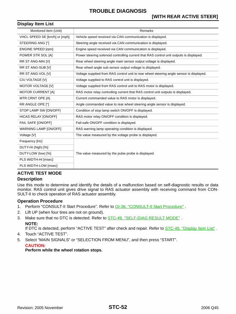
STC-52
[WITH REAR ACTIVE STEER]TROUBLE DIAGNOSIS
Revision: 2005 November 2006 Q45
Display Item List
ACTIVE TEST MODEDescriptionUse this mode to determine and identify the details of a malfunction based on self-diagnostic results or datamonitor. RAS control unit gives drive signal to RAS actuator assembly with receiving command from CON-SULT-II to check operation of RAS actuator assembly.
Operation Procedure1. Perform “CONSULT-II Start Procedure”. Refer to GI-36, "CONSULT-II Start Procedure" .2. Lift UP (when four tires are not on ground).3. Make sure that no DTC is detected. Refer to STC-49, "SELF-DIAG RESULT MODE" .
NOTE:If DTC is detected, perform “ACTIVE TEST” after check and repair. Refer to STC-49, "Display Item List" .
4. Touch “ACTIVE TEST”.5. Select “MAIN SIGNALS” or “SELECTION FROM MENU”, and then press “START”.
CAUTION:Perform while the wheel rotation stops.
Monitored item (Unit) Remarks
VHCL SPEED SE [km/h] or [mph] Vehicle speed received via CAN communication is displayed.
STEERING ANG [°] Steering angle received via CAN communication is displayed.
ENGINE SPEED [rpm] Engine speed received via CAN communication is displayed.
POWER STR SOL [A] Power steering solenoid controlling current that RAS control unit outputs is displayed.
RR ST ANG-MAI [V] Rear wheel steering angle main sensor output voltage is displayed.
RR ST ANG-SUB [V] Rear wheel angle sub sensor output voltage is displayed.
RR ST ANG-VOL [V] Voltage supplied from RAS control unit to rear wheel steering angle sensor is displayed.
C/U VOLTAGE [V] Voltage supplied to RAS control unit is displayed.
MOTOR VOLTAGE [V] Voltage supplied from RAS control unit to RAS motor is displayed.
MOTOR CURRENT [A] RAS motor relay controlling current that RAS control unit outputs is displayed.
MTR CRNT OPE [A] Current commanded value to RAS motor is displayed.
RR ANGLE OPE [°] Angle commanded value to rear wheel steering angle sensor is displayed.
STOP LAMP SW [ON/OFF] Condition of stop lamp switch ON/OFF is displayed.
HICAS RELAY [ON/OFF] RAS motor relay ON/OFF condition is displayed.
FAIL SAFE [ON/OFF] Fail-safe ON/OFF condition is displayed.
WARNING LAMP [ON/OFF] RAS warning lamp operating condition is displayed.
Voltage [V] The value measured by the voltage probe is displayed.
Frequency [Hz]
The value measured by the pulse probe is displayed.
DUTY-HI (high) [%]
DUTY-LOW (low) [%]
PLS WIDTH-HI [msec]
PLS WIDTH-LOW [msec]

TROUBLE DIAGNOSIS
STC-53
[WITH REAR ACTIVE STEER]
C
D
E
F
H
I
J
K
L
M
A
B
STC
Revision: 2005 November 2006 Q45
6. Start “ACTIVE TEST” after pressing “ON” ( ) in the indicator.7. Operate with the following:
When turning the steering wheel right or left, the rear wheelturns in the same direction.
Steering wheel is not turned, the rear wheel turns left and right5 times.
RAS CONTROL UNIT PART NUMBER MODEIgnore the RAS control unit part number displayed in the “ECU PART NUMBER”.Refer to parts catalog to order the RAS control unit.
Self-Diagnostic Procedure NGS0006T
SELF-DIAGNOSTIC PROCEDURE (WITH CONSULT-II)Refer to STC-49, "SELF-DIAG RESULT MODE" .
SELF-DIAGNOSTIC PROCEDURE (WITHOUT CONSULT-II)DescriptionThe RAS warning lamp in the combination meter will flicker according to the self-diagnostic results. As for thedetails of the RAS warning lamp flickering patterns, refer to STC-53, "Diagnostic Procedure" .
Diagnostic Procedure1. Start engine.2. Perform the following procedure within 10 seconds after engine start.
Turn steering wheel left and right at 20° or more and 5 times Depress the brake pedal 5 times or more
3. Read the flickering of RAS warning lamp. Refer to STC-53, "Judgement Self-diagnosis" .NOTE:When the RAS warning lamp flashes 4 Hz and continues repeating it, the system is normal.
Judgement Self-diagnosisWhen a malfunction is detected, the malfunction route is indicated by flickering of the RAS warning lamp.
NOTE:When the RAS warning lamp flashes 4 Hz and continues repeating it, the system is normal.
Monitored item Active test “ON”
STEERING ANG 0° (Neutral) R 90° L90°
RR ST ANG-MAI 2.4 V Approx. 4.4 V Approx. 0.4 V
RR ST ANG-SUB 2.4 V Approx. 4.4 V Approx. 0.4 V
MOTOR CURRENTNo output
(Approx. 0 A)Output (change)
SGIA1451E
SGIA1453E

STC-54
[WITH REAR ACTIVE STEER]TROUBLE DIAGNOSIS
Revision: 2005 November 2006 Q45
ERASE SELF-DIAGNOSIS In order to make it easier to find the cause of hard-to-duplicate malfunctions, malfunction information is
stored into the control unit as necessary during use by the user. This memory is not erased no matter howmany times the ignition switch is turned ON and OFF.
However, this information is erased by turning ignition switch “OFF” after performing self-diagnostics or byerasing the memory using the CONSULT-II. Refer to STC-40, "How to Perform Trouble Diagnosis" .
Flickering pattern Items Diagnostic item is detected when... Check item
11 RAS control unit Malfunction has occurred inside RAS control unit.
STC-56, "DTC C1900, C1901, C1905, C1906, C1907, C1908, C1922, C1927, C1928 CON-TROL UNIT", STC-56, "DTC C1925 AD CON-VERTER" or STC-60, "DTC C1909 CON-TROL UNIT"
12 Motor power supply Battery voltage circuit malfunction of RAS motorSTC-62, "DTC C1911, C1912 MOTOR VOLT-AGE"
13 Motor outputWhen the RAS motor current value is 10 A or more, actual output is excessively low and the condition continues for some time.
STC-57, "DTC C1902, C1903, C1904, C1910, C1913 MOTOR OUT-PUT"
21 Vehicle speed signal
Malfunction is detected in vehicle speed signal that is output from VDC/TCS/ABS control unit through CAN communication.
Improper signal is input vehicle speed.
STC-72, "DTC C1919 VEHICLE SPEED SEN"
22 Steering angle sensor signal
Malfunction is detected in steering angle sensor signal that is output from steering angle sensor through CAN communication.
Improper signal is input steering angle sensor.
STC-72, "DTC C1920, C1923, C1924, C1926 STEERING ANGLE SEN"
24Rear wheel steering angle (main)
The rear wheel steering angle sensor (main) input signal is malfunctioning for some time against the sensor power supply value.
STC-67, "DTC C1914, C1915, C1916, C1917, C1918 RR ST ANGLE SENSOR"
25Rear wheel steering angle (sub)
When the main sensor input signal is 2.4 - 2.6 V, the rear wheel steering angle sensor (sub) input signal is malfunctioning for some time compared to the sensor power supply value.
STC-67, "DTC C1914, C1915, C1916, C1917, C1918 RR ST ANGLE SENSOR"
26 VDC
Malfunction is detected in VDC malfunction signal that is output from VDC/TCS/ABS control unit through CAN communication.
VDC/TCS/ABS control unit outputs the malfunction signal.
Improper signal is input VDC malfunction signal.
STC-74, "DTC C1929 VDC"
33 Engine speed signal
Malfunction is detected in engine speed signal that is output from ECM through CAN communication.
Improper signal is input engine speed.
STC-73, "DTC C1921 ENG REV SIGNAL"
No flickering Stop lamp switch Stop lamp switch circuit is shorted or open.STC-80, "Stop Lamp Switch"

TROUBLE DIAGNOSIS
STC-55
[WITH REAR ACTIVE STEER]
C
D
E
F
H
I
J
K
L
M
A
B
STC
Revision: 2005 November 2006 Q45
Inspections before Trouble Diagnosis NGS0006N
Inspect for power steering fluid leakage and check the power steering fluid level. Refer to PS-6, "POWERSTEERING FLUID" .
Power steering components (gears, oil pump, pipes, etc.) are free from leakage, and that oil level is cor-rect.
Tires are inflated to specified pressure and are of specified size, and that steering wheel is a genuine Nis-san part.
Suspension utilizes the original design, and is free of modifications which increase vehicle weight. Wheel alignment is adjusted properly.
Trouble Diagnosis Chart for Symptoms NGS0006Q
If RAS warning lamp turns ON, perform self-diagnosis. Refer to STC-53, "Self-Diagnostic Procedure" .
Symptom Condition Check item Reference page
RAS warning lamp does not turn ON for approx.1 second when the ignition switch is turned to ON.
Ignition switch: ON
Power supply
STC-85Combination meter
RAS control unit
The steering force of steering wheel is not changed smoothly according to the vehicle speed.
While driving
Vehicle speed sensor
STC-87
Stop lamp switch
Power steering solenoid valve
RAS actuator assembly
RAS control unit
Hard steering when fully turning the steering wheel.
Vehicle stopped or while low speed driving
Vehicle speed sensor
STC-88Stop lamp switch
Power steering solenoid valve
Light steering when driving at a high speed. While high speed drivingVehicle speed sensor
STC-89Power steering solenoid valve

STC-56
[WITH REAR ACTIVE STEER]TROUBLE DIAGNOSIS FOR SYSTEM
Revision: 2005 November 2006 Q45
TROUBLE DIAGNOSIS FOR SYSTEM PFP:00000
DTC C1900, C1901, C1905, C1906, C1907, C1908, C1922, C1927, C1928 CON-TROL UNIT NGS0008H
Check the following if “CONTROL UNIT [ABNORMAL1] [C1900]”, “CONTROL UNIT [ABNORMAL2][C1901]”, “CONTROL UNIT [ABNORMAL3] [C1905]”, “CONTROL UNIT [ABNORMAL5] [C1906]”, “CON-TROL UNIT [ABNORMAL4] [C1907]”, “CONTROL UNIT [ABNORMAL7] [C1908]”, “CONTROL UNIT[ABNORMAL8] [C1922]”, “CONTROL UNIT [ABNORMAL5] [C1927]” or “CONTROL UNIT [ABNORMAL9][C1928]” is detected in self-diagnosis results with CONSULT-II or “flickering pattern for 11” is detected inself-diagnosis results without CONSULT-II.
DIAGNOSTIC PROCEDURE
1. INSPECTION START
Is CONSULT-II available?YES or NOYES >> GO TO 2.NO >> GO TO 3.
2. PERFORM SELF-DIAGNOSIS (WITH CONSULT-II)
With CONSULT-II1. Turn ignition switch “ON”. (Do not start engine.)2. Select “SELF-DIAG RESULTS” mode for “RAS/HICAS” with CONSULT-II.3. Touch “ERASE”.4. Turn ignition switch “OFF” and wait at least 10 seconds.5. Perform the self-diagnosis again.Is the “CONTROL UNIT [ABNORMAL1] [C1900]”, “CONTROL UNIT [ABNORMAL2] [C1901]”, “CONTROLUNIT [ABNORMAL3] [C1905]”, “CONTROL UNIT [ABNORMAL5] [C1906]”, “CONTROL UNIT [ABNORMAL4][C1907]”, “CONTROL UNIT [ABNORMAL7] [C1908]”, “CONTROL UNIT [ABNORMAL8] [C1922]”, “AD CON-VERTER [C1925]”, “CONTROL UNIT [ABNORMAL5] [C1927]” or “CONTROL UNIT [ABNORMAL9] [C1928]”displayed?YES >> Replace RAS control unit. Refer to STC-90, "Removal and Installation" .NO >> INSPECTION END
3. PERFORM SELF-DIAGNOSIS (WITHOUT CONSULT-II)
Without CONSULT-II1. Perform the self-diagnosis and then erase self-diagnostic results. Refer to STC-53, "SELF-DIAGNOSTIC
PROCEDURE (WITHOUT CONSULT-II)" and STC-54, "ERASE SELF-DIAGNOSIS" .2. Perform the self-diagnosis again.Do the self-diagnostic results indicate RAS control unit?YES >> Replace RAS control unit. Refer to STC-90, "Removal and Installation" .NO >> INSPECTION END
DTC C1925 AD CONVERTER NGS000CS
Check the following if “AD CONVERTER [C1925]” is detected in self-diagnosis results with CONSULT-IIor “flickering pattern for 11” is detected in self-diagnosis results without CONSULT-II.
Refer to STC-56, "DTC C1900, C1901, C1905, C1906, C1907, C1908, C1922, C1927, C1928 CONTROLUNIT" .

TROUBLE DIAGNOSIS FOR SYSTEM
STC-57
[WITH REAR ACTIVE STEER]
C
D
E
F
H
I
J
K
L
M
A
B
STC
Revision: 2005 November 2006 Q45
DTC C1902, C1903, C1904, C1910, C1913 MOTOR OUTPUT NGS0008I
Check the following if “MOTOR OUTPUT [REV CURRENT] [C1902]”, “MOTOR OUTPUT [NO CURRENT][C1903]”, “MOTOR OUTPUT [OVERCURRENT] [C1904]”, “MOTOR OUTPUT [MOTOR LOCK] [C1910]”or “MOTOR OUTPUT [ABNORML SIG] [C1913]” is detected in self-diagnosis results with CONSULT-II or“flickering pattern for 13” is detected in self-diagnosis results without CONSULT-II.
CONSULT-II REFERENCE VALUE IN DATA MONITOR MODEData are reference value.
RAS CONTROL UNIT TERMINALS AND REFERENCE VALUEData are reference value and are measured between each terminal and ground.
CAUTION:When using a circuit tester to measure voltage for inspection, be sure not to extend forcibly any connector terminals.
Monitored item Content Condition Display value
MOTOR VOLTAGE [V]Monitored value of voltage at RAS motor
Ignition switch: ON Battery voltage
Ignition switch: OFF 0 V
MOTOR CURRENT [A]Monitored value of current at RAS motor
During RAS actuator assembly turning Approx. 0 - 20 A
MTR CRNT OPE [A]Current commanded value to RAS motor
During RAS actuator assembly turning Approx. -20 - 20 A
TerminalWire color
Item Condition Data (Approx.)
38 G/YRAS motor output voltage(right)
While RAS motor is operating for right Battery voltage
While RAS motor is operating for left 0 V
39 G/RRAS motor output voltage(left)
While RAS motor is operating for right 0 V
While RAS motor is operating for left Battery voltage

STC-58
[WITH REAR ACTIVE STEER]TROUBLE DIAGNOSIS FOR SYSTEM
Revision: 2005 November 2006 Q45
DIAGNOSTIC PROCEDURE
1. CHECK RAS MOTOR SIGNAL
With CONSULT-II1. Start engine.2. Select “DATA MONITOR” mode for “RAS/HICAS” with CONSULT-II.3. Read out the value of “MOTOR VOLTAGE”, “MOTOR CUR-
RENT” and “MTR CRNT OPE”.
Without CONSULT-II1. Start engine.2. Check voltage between RAS control unit harness connector (A)
terminals and ground.
OK or NGOK >> GO TO 4.NG >> GO TO 2.
2. CHECK HARNESS BETWEEN RAS CONTROL UNIT AND RAS MOTOR
1. Turn ignition switch “OFF”.2. Disconnect RAS control unit harness connector and RAS motor harness connector.3. Check continuity between the following terminals.– RAS control unit harness connector (A) B39 terminal 38 and
RAS motor harness connector (B) B82 terminal 1.– RAS control unit harness connector (A) B39 terminal 39 and
RAS motor harness connector (B) B82 terminal 2.
Also check harness for short to ground and short to power.OK or NGOK >> GO TO 3.NG >> Repair or replace damaged parts.
Monitored item Condition Display value
MOTOR VOLTAGEIgnition switch: ON Battery voltage
Ignition switch: OFF 0 V
MOTOR CURRENT During RAS actuator assembly turning Approx. 0 - 20 A
MTR CRNT OPE During RAS actuator assembly turning Approx. -20 - 20 A
Connector Terminal ConditionVoltage
(Approx.)
B39
38 - Ground
While RAS motor is operating for rightBattery voltage
While RAS motor is operating for left 0 V
39 - Ground
While RAS motor is operating for right 0 V
While RAS motor is operating for leftBattery voltage
SGIA1469E
SGIA1470E
Continuity should exist.
SGIA1472E

TROUBLE DIAGNOSIS FOR SYSTEM
STC-59
[WITH REAR ACTIVE STEER]
C
D
E
F
H
I
J
K
L
M
A
B
STC
Revision: 2005 November 2006 Q45
3. CHECK RAS MOTOR
1. Turn ignition switch “OFF”.2. Disconnect RAS motor harness connector.3. Remove RAS motor. Refer to STC-92, "COMPONENTS" .4. Check operation by supply 6 V (B) voltage to RAS motor con-
nector (A) terminals 1 and 2.CAUTION: Never supply 12 V voltage (battery, etc.) to the RAS
motor. Never operate RAS motor for more than 1 second. Be careful not to overheat the harness.
5. Check continuity between RAS motor connector (A) terminals 1and 2.
OK or NGOK >> GO TO 4.NG >> Replace RAS motor.
4. CHECK RAS CONTROL UNIT
Check RAS control unit input/output signal. Refer to STC-47, "RAS Control Unit Input/Output Signal Refer-ence Values" .OK or NGOK >> GO TO 5.NG >> Check RAS control unit pin terminals for damage or loose connection with harness connector. If
any items are damaged, repair or replace damaged parts.
5. CHECK DTC
Perform the self-diagnosis, after driving a vehicle for a while.OK or NGOK >> INSPECTION ENDNG >> Replace RAS control unit. Refer to STC-90, "Removal and Installation" .
Terminal Actuator motor
1 (Positive) - 2 (Negative) Clockwise rotate
2 (Positive) - 1 (Negative) Counterclockwise rotateSGIA1473E
1 – 2 : Approx. 0.45 Ω
SGIA1474E

STC-60
[WITH REAR ACTIVE STEER]TROUBLE DIAGNOSIS FOR SYSTEM
Revision: 2005 November 2006 Q45
DTC C1909 CONTROL UNIT NGS0006X
Check the following if “CONTROL UNIT [ABNORMAL6] [C1909]” is detected in self-diagnosis results withCONSULT-II or “flickering pattern for 11” is detected in self-diagnosis results without CONSULT-II.
CONSULT-II REFERENCE VALUE IN DATA MONITOR MODEData are reference value.
RAS CONTROL UNIT TERMINALS AND REFERENCE VALUEData are reference value and are measured between each terminal and ground.
CAUTION:When using a circuit tester to measure voltage for inspection, be sure not to extend forcibly any connector terminals.
DIAGNOSTIC PROCEDURE
1. INSPECTION START
Is CONSULT-II available?YES or NOYES >> GO TO 2.NO >> GO TO 3.
2. CHECK POWER SUPPLY SIGNAL
With CONSULT-II1. Start engine.2. Select “DATA MONITOR” mode for “RAS/HICAS” with CONSULT-II.3. Read out the value of “C/U VOLTAGE”.
OK or NGOK >> GO TO 5.NG >> GO TO 3.
Monitored item Content Condition Display value
C/U VOLTAGE [V]Power supply voltage for RAS control unit
Ignition switch: ON Battery voltage
Ignition switch: OFF —
TerminalWire color
Item Condition Data (Approx.)
27 GY Ignition switchIgnition switch: ON Battery voltage
Ignition switch: OFF 0 V
34 B Ground Always 0 V
Monitored item Condition Display value
C/U VOLTAGE Ignition switch: ON Battery voltage
SGIA1468E

TROUBLE DIAGNOSIS FOR SYSTEM
STC-61
[WITH REAR ACTIVE STEER]
C
D
E
F
H
I
J
K
L
M
A
B
STC
Revision: 2005 November 2006 Q45
3. CHECK POWER SUPPLY
1. Turn ignition switch “OFF”.2. Disconnect RAS control unit harness connector.3. Check voltage between RAS control unit harness connector (A)
terminal and ground.
4. Turn ignition switch “ON”. (Do not start engine.)5. Check voltage between RAS control unit harness connector (A)
terminal and ground.
OK or NGOK >> GO TO 4.NG >> Check the following. If any items are damaged, repair or
replace damaged parts. 10 A fuse [No. 7 located in the fuse block (J/B) No.1].
Refer to PG-2, "POWER SUPPLY ROUTING" . Harness for short or open between ignition switch and RAS control unit harness connector B39
terminal 27. Ignition switch. Refer to PG-2, "POWER SUPPLY ROUTING" .
4. CHECK GROUND CIRCUIT
1. Turn ignition switch “OFF”.2. Disconnect RAS control unit harness connector.3. Check continuity between RAS control unit harness connector
(A) B39 terminal 34 and ground.
Also check harness for short to power.OK or NGOK >> GO TO 5.NG >> Repair open circuit or short to power in harness or con-
nectors.
5. CHECK RAS CONTROL UNIT
Check RAS control unit input/output signal. Refer to STC-47, "RAS Control Unit Input/Output Signal Refer-ence Values" .OK or NGOK >> GO TO 6.NG >> Check RAS control unit pin terminals for damage or loose connection with harness connector. If
any items are damaged, repair or replace damaged parts.
Connector Terminal Voltage (Approx.)
B39 27 - Ground 0 V
SGIA1461E
Connector Terminal Voltage (Approx.)
B39 27 - Ground Battery voltage
SGIA1462E
Continuity should exist.
SGIA1463E

STC-62
[WITH REAR ACTIVE STEER]TROUBLE DIAGNOSIS FOR SYSTEM
Revision: 2005 November 2006 Q45
6. CHECK DTC
Perform the self-diagnosis, after driving a vehicle for a while.OK or NGOK >> INSPECTION ENDNG >> Replace RAS control unit. Refer to STC-90, "Removal and Installation" .
DTC C1911, C1912 MOTOR VOLTAGE NGS0008J
Check the following if “MOTOR VOLTAGE [LOW VOLTEGE] [C1911]” or “MOTOR VOLTAGE [BADOBSTRCT] [C1912]” is detected in self-diagnosis results with CONSULT-II or “flickering pattern for 12” isdetected in self-diagnosis results without CONSULT-II.
CONSULT-II REFERENCE VALUE IN DATA MONITOR MODEData are reference value.
RAS CONTROL UNIT TERMINALS AND REFERENCE VALUEData are reference value and are measured between each terminal and ground.
CAUTION:When using a circuit tester to measure voltage for inspection, be sure not to extend forcibly any connector terminals.
DIAGNOSTIC PROCEDURE
1. INSPECTION START
Is CONSULT-II available?YES or NOYES >> GO TO 2.NO >> GO TO 3.
Monitored item Content Condition Display value
C/U VOLTAGE [V]Power supply voltage for RAS control unit
Ignition switch: ON Battery voltage
Ignition switch: OFF —
MOTOR VOLTAGE [V]Monitored value of voltage at RAS motor
Ignition switch: ON Battery voltage
Ignition switch: OFF 0 V
HICAS RELAY [ON/OFF] RAS motor relay conditionIgnition switch: ON ON
Ignition switch: OFF OFF
TerminalWire color
Item Condition Data (Approx.)
25 L/W RAS motor relayIgnition switch: ON Battery voltage
Ignition switch: OFF 0 V
27 GY Ignition switchIgnition switch: ON Battery voltage
Ignition switch: OFF 0 V
37 L/YPower supply(RAS motor)
Ignition switch: ON Battery voltage
Ignition switch: OFF 0 V

TROUBLE DIAGNOSIS FOR SYSTEM
STC-63
[WITH REAR ACTIVE STEER]
C
D
E
F
H
I
J
K
L
M
A
B
STC
Revision: 2005 November 2006 Q45
2. CHECK POWER SUPPLY SIGNAL
With CONSULT-II1. Start engine.2. Select “DATA MONITOR” mode for “RAS/HICAS” with CONSULT-II.3. Read out the value of “C/U VOLTAGE”, “MOTOR VOLTAGE”
and “HICAS RELAY”.
OK or NGOK >> GO TO 7.NG >> GO TO 3.
Monitored item Condition Display value
C/U VOLTAGE Ignition switch: ON Battery voltage
MOTOR VOLTAGEIgnition switch: ON Battery voltage
Ignition switch: OFF 0 V
HICAS RELAYIgnition switch: ON ON
Ignition switch: OFF OFFSGIA1477E

STC-64
[WITH REAR ACTIVE STEER]TROUBLE DIAGNOSIS FOR SYSTEM
Revision: 2005 November 2006 Q45
3. CHECK POWER SUPPLY
1. Turn ignition switch “OFF”.2. Disconnect RAS control unit harness connector.3. Check voltage between RAS control unit harness connector (A)
terminals and ground.
4. Turn ignition switch “ON”. (Do not start engine.)5. Check voltage between RAS control unit harness connector (A)
terminals and ground.
OK or NGOK >> GO TO 4.NG >> Check the following. If any items are damaged, repair or
replace damaged parts. 10 A fuse [No. 7 located in the fuse block (J/B) No.1]. Refer to PG-2, "POWER SUPPLY ROUT-
ING" . 20 A fuse [No. 76 located in the fuse, fusible link and relay box]. Refer to PG-2, "POWER SUP-
PLY ROUTING" . Harness for short or open between ignition switch and RAS control unit harness connector B39
terminals 27. Harness for short or open between battery and RAS control unit harness connector B39 termi-
nals 37. Harness for short or open between RAS control unit harness connector B39 terminal 25 and
RAS motor relay harness connector B42 terminal 1. Harness for open circuit or short to power between RAS motor relay harness connector B42
terminal 2 and ground. Battery. Refer to PG-2, "POWER SUPPLY ROUTING" .
Connector Terminal Voltage (Approx.)
B39
25 - Ground
0 V27 - Ground
37 - Ground
SGIA1464E
Connector Terminal Voltage (Approx.)
B39
25 - Ground
Battery voltage27 - Ground
37 - Ground
SGIA1465E

TROUBLE DIAGNOSIS FOR SYSTEM
STC-65
[WITH REAR ACTIVE STEER]
C
D
E
F
H
I
J
K
L
M
A
B
STC
Revision: 2005 November 2006 Q45
4. CHECK GROUND CIRCUIT
1. Turn ignition switch “OFF”.2. Disconnect RAS control unit harness connector.3. Check continuity between RAS control unit harness connector
(A) B39 terminal 40 and ground.
Also check harness for short to power.OK or NGOK >> GO TO 5.NG >> Check the following. If any items are damaged, repair or
replace damaged parts. Harness open circuit or short to power between noise
suppressor harness connector B41 terminal 4 andRAS control unit harness connector B39 terminal 40.
Harness open circuit or short to power between noise suppressor harness connector B40 termi-nal 2 and ground.
5. CHECK RAS MOTOR RELAY
1. Turn ignition switch “OFF”.2. Remove RAS motor relay. Refer to STC-41, "Component Parts Location" .3. Apply 12 V direct current between RAS motor relay connector
B42 terminals 1 and 2.4. Check continuity between RAS motor relay connector B42 ter-
minals 3 and 5.
5. Check continuity between RAS motor relay connector B42 ter-minals 1 and 2.
OK or NGOK >> GO TO 6.NG >> Replace RAS motor relay.
6. CHECK NOISE SUPPRESSOR
1. Turn ignition switch “OFF”.2. Remove noise suppressor. Refer to STC-41, "Component Parts Location" .3. Check noise suppressor connector (A) continuity between the
following terminals.
OK or NGOK >> GO TO 7.NG >> Replace RAS motor relay.
Continuity should exist.
SGIA1466E
Terminal Condition Continuity
3 - 51 2 V direct current supply between terminals 1 and 2 Yes
OFF No
1 – 2 : 74 ΩSGIA1286E
1 – 3 : Continuity should exist.1 – 2 : Continuity should no exist.1 – 4 : Continuity should no exist.2 – 1 : Continuity should no exist.2 – 3 : Continuity should no exist.2 – 4 : Continuity should exist.
SGIA1467E

STC-66
[WITH REAR ACTIVE STEER]TROUBLE DIAGNOSIS FOR SYSTEM
Revision: 2005 November 2006 Q45
7. CHECK RAS CONTROL UNIT
Check RAS control unit input/output signal. Refer to STC-47, "RAS Control Unit Input/Output Signal Refer-ence Values" .OK or NGOK >> GO TO 8.NG >> Check RAS control unit pin terminals for damage or loose connection with harness connector. If
any items are damaged, repair or replace damaged parts.
8. CHECK DTC
Perform the self-diagnosis, after driving a vehicle for a while.OK or NGOK >> INSPECTION ENDNG >> Replace RAS control unit. Refer to STC-90, "Removal and Installation" .

TROUBLE DIAGNOSIS FOR SYSTEM
STC-67
[WITH REAR ACTIVE STEER]
C
D
E
F
H
I
J
K
L
M
A
B
STC
Revision: 2005 November 2006 Q45
DTC C1914, C1915, C1916, C1917, C1918 RR ST ANGLE SENSOR NGS0008K
Check the following if “RR ST ANGLE SENSOR [ABNORML VOL] [C1914]”, “RR ST ANGLE SENSOR[MAIN SIGNAL] [C1915]”, “RR ST ANGLE SENSOR [SUB SIGNAL] [C1916]”, “RR ST ANGLE SENSOR[OFFSET SIG1] [C1917]” or “RR ST ANGLE SENSOR [OFFSET SIG2] [C1918]” is detected in self-diag-nosis results with CONSULT-II or “flickering pattern for 24 or 25” is detected in self-diagnosis results with-out CONSULT-II.
CONSULT-II REFERENCE VALUE IN DATA MONITOR MODEData are reference value.
RAS CONTROL UNIT TERMINALS AND REFERENCE VALUEData are reference value and are measured between each terminal and ground.
CAUTION:When using a circuit tester to measure voltage for inspection, be sure not to extend forcibly any connector terminals.
Monitored item Content Condition Display value
RR ST ANG-MAI [V]Rear wheel steering angle (main) sensor output voltage
RAS actuator assembly turned full right Approx. 4.4 V
RAS actuator assembly neutral Approx. 2.4 V
RAS actuator assembly turned full left Approx. 0.4 V
RR ST ANG-SUB [V]Rear wheel steering angle (sub) sensor output voltage
RAS actuator assembly turned full right Approx. 4.4 V
RAS actuator assembly neutral Approx. 2.4 V
RAS actuator assembly turned full left Approx. 0.4 V
RR ST ANG-VOL [V]Rear wheel steering angle sensor input voltage
Ignition switch: ON Approx. 5 V
Ignition switch: OFF 0 V
RR ANGLE OPE [°]Rear wheel steering angle detected by rear wheel steer-ing angle sensor
RAS actuator assembly turned full right Approx. 1°
RAS actuator assembly neutral Approx. 0°
RAS actuator assembly turned full left Approx. -1°
TerminalWire color
Item Condition Data (Approx.)
4 GRear wheel steering angle (main) sensor output voltage
RAS actuator assembly turned full right 4.4 V
RAS actuator assembly neutral 2.4 V
RAS actuator assembly turned full left 0.4 V
5 WPower supply(rear wheel steering angle sensor)
Ignition switch: ON 5 V
Ignition switch: OFF 0 V
7 RRear wheel steering angle (sub) sensor output voltage
RAS actuator assembly turned full right 4.4 V
RAS actuator assembly neutral 2.4 V
RAS actuator assembly turned full left 0.4 V
15 BGround(rear wheel steering angle sensor)
Always 0 V

STC-68
[WITH REAR ACTIVE STEER]TROUBLE DIAGNOSIS FOR SYSTEM
Revision: 2005 November 2006 Q45
DIAGNOSTIC PROCEDURE
1. CHECK REAR WHEEL STEERING ANGLE SENSOR SIGNAL
With CONSULT-II1. Start engine.2. Select “DATA MONITOR” mode for “RAS/HICAS” with CONSULT-II.3. Read out the value of “RR ST ANG-MAI”, “RR ST ANG-SUB”,
“RR ST ANG-VOL” and “RR ANGLE OPE”.
Without CONSULT-II1. Start engine.2. Check signal between RAS control unit harness connector (A)
terminals and ground.
OK or NGOK >> GO TO 6.NG >> GO TO 2.
Monitored item Condition Display value
RR ST ANG-MAI
RAS actuator assembly turned full right Approx. 4.4 V
RAS actuator assembly neutral Approx. 2.4 V
RAS actuator assembly turned full left Approx. 0.4 V
RR ST ANG-SUB
RAS actuator assembly turned full right Approx. 4.4 V
RAS actuator assembly neutral Approx. 2.4 V
RAS actuator assembly turned full left Approx. 0.4 V
RR ST ANG-VOLIgnition switch: ON Approx. 5 V
Ignition switch: OFF 0 V
RR ANGLE OPE
RAS actuator assembly turned full right Approx. 1°
RAS actuator assembly neutral Approx. 0°
RAS actuator assembly turned full left Approx. -1°
SGIA1479E
Connector Terminal ConditionVoltage
(Approx.)
B39
4 - Ground
RAS actuator assembly turned full right 4.4 V
RAS actuator assembly neutral 2.4 V
RAS actuator assembly turned full left 0.4 V
5 - Ground
Ignition switch: ON 5 V
Ignition switch: OFF 0 V
7 - Ground
RAS actuator assembly turned full right 4.4 V
RAS actuator assembly neutral 2.4 V
RAS actuator assembly turned full left 0.4 V
15 - Ground
Always 0 V
SGIA1480E

TROUBLE DIAGNOSIS FOR SYSTEM
STC-69
[WITH REAR ACTIVE STEER]
C
D
E
F
H
I
J
K
L
M
A
B
STC
Revision: 2005 November 2006 Q45
2. CHECK HARNESS BETWEEN RAS CONTROL UNIT AND REAR WHEEL STEERING ANGLE SEN-SOR
1. Turn ignition switch “OFF”.2. Disconnect RAS control unit harness connector and rear wheel steering angle sensor harness connector.3. Check continuity between the following terminals.– RAS control unit harness connector (A) B39 terminal 4 and rear
wheel steering angle sensor harness connector (B) B81 terminal4.
– RAS control unit harness connector (A) B39 terminal 5 and rearwheel steering angle sensor harness connector (B) B81 terminal1.
– RAS control unit harness connector (A) B39 terminal 7 and rearwheel steering angle sensor harness connector (B) B81 terminal2.
– RAS control unit harness connector (A) B39 terminal 15 andrear wheel steering angle sensor harness connector (B) B81 ter-minal 3.
Also check harness for short to ground and short to power.OK or NGOK >> GO TO 3.NG >> Repair or replace damaged parts.
3. CHECK REAR WHEEL STEERING SENSOR POWER SUPPLY
1. Turn ignition switch “OFF”.2. Disconnect rear wheel steering sensor harness connector.3. Check voltage between rear wheel steering sensor harness con-
nector (A) terminal 1 and ground.
4. Turn ignition switch “ON”. (Do not start engine.)5. Check voltage between rear wheel steering sensor harness con-
nector (A) terminal 1 and ground.
OK or NGOK >> GO TO 4.NG >> Replace RAS control unit. Refer to STC-90, "Removal
and Installation" .
Continuity should exist.
SGIA1484E
Connector Terminal Voltage (Approx.)
B81 1 - Ground 0 V
SGIA1481E
Connector Terminal Voltage (Approx.)
B81 1 - Ground 5 V
SGIA1483E

STC-70
[WITH REAR ACTIVE STEER]TROUBLE DIAGNOSIS FOR SYSTEM
Revision: 2005 November 2006 Q45
4. CHECK (1): REAR WHEEL STEERING ANGLE SENSOR
With CONSULT-II1. Start engine.2. Select “DATA MONITOR” mode for “RAS/HICAS” with CONSULT-II.3. Read out the value of “RR ST ANG-MAI” and “RR ST ANG-
SUB”.
Without CONSULT-II1. Start engine.2. Check signal between RAS control unit harness connector (A)
terminals and ground.
Is there approximately 1 V difference between main output and suboutput?YES >> Replace rear wheel steering angle sensor. Perform the
neutral position adjustment after replacing rear wheelsteering angle sensor. Refer toSTC-92, "Neutral Position" .
NO >> GO TO 5.
Monitored item Condition Display value
RR ST ANG-MAI RAS actuator assembly neutral Approx. 2.4 V
RR ST ANG-SUB RAS actuator assembly neutral Approx. 2.4 V
SGIA1487E
Connector Terminal ConditionVoltage
(Approx.)
B394 - Ground RAS actuator assembly neutral 2.4 V
7 - Ground RAS actuator assembly neutral 2.4 V
SGIA1509E

TROUBLE DIAGNOSIS FOR SYSTEM
STC-71
[WITH REAR ACTIVE STEER]
C
D
E
F
H
I
J
K
L
M
A
B
STC
Revision: 2005 November 2006 Q45
5. CHECK (2): REAR WHEEL STEERING ANGLE SENSOR
1. Turn ignition switch “OFF”.2. Disconnect rear wheel steering angle sensor harness connector.3. Remove rear wheel steering angle sensor.4. Check resistance between rear wheel steering angle sensor
connector (A) B81 terminals 1 and 3.
5. While turning the rear wheel steering angle sensor clockwise orcounterclockwise, check rear wheel steering angle sensor con-nector (A) B81 terminals 1 and 2, 4.
6. Perform the neutral position adjustment of rear wheel steeringangle sensor after checking. Refer to STC-92, "Neutral Position".
OK or NG OK >> GO TO 6. NG >> Replace rear wheel steering angle sensor. Perform the neutral position adjustment after replacing
rear wheel steering angle sensor. Refer toSTC-92, "Neutral Position" .
6. CHECK RAS CONTROL UNIT
Check RAS control unit input/output signal. Refer to STC-47, "RAS Control Unit Input/Output Signal Refer-ence Values" .OK or NGOK >> GO TO 7.NG >> Check RAS control unit pin terminals for damage or loose connection with harness connector. If
any items are damaged, repair or replace damaged parts.
7. CHECK DTC
Perform the self-diagnosis, after driving a vehicle for a while.OK or NGOK >> INSPECTION ENDNG >> Replace RAS control unit. Refer to STC-90, "Removal and Installation" .
1 - 3 : 1 kΩ
SGIA1485E
1 - 2 : 1.2 k – 1.5 kΩ1 - 4 : 1.2 k – 1.5 kΩ
SGIA1486E

STC-72
[WITH REAR ACTIVE STEER]TROUBLE DIAGNOSIS FOR SYSTEM
Revision: 2005 November 2006 Q45
DTC C1919 VEHICLE SPEED SEN NGS0008L
Check the following if “VEHICLE SPEED SEN [NO SIGNAL] [C1919]” is detected in self-diagnosis resultswith CONSULT-II or “flickering pattern for 21” is detected in self-diagnosis results without CONSULT-II.
DIAGNOSTIC PROCEDURE
1. CHECK DTC WITH VDC/TCS/ABS CONTROL UNIT
Perform self-diagnosis with VDC/TCS/ABS control unit. Refer to BRC-24, "SELF-DIAG RESULT MODE" .Is any malfunction detected by self-diagnosis?YES >> Check the malfunctioning system.NO >> GO TO 2.
2. CHECK RAS CONTROL SYSTEM
Perform self-diagnosis with RAS control unit. Refer to STC-49, "SELF-DIAG RESULT MODE" .Is the “CAN COMM [U1000]” or “CONTROL UNIT (CAN) [U1010]” displayed?YES >> Perform trouble diagnosis for DTC U1000 CAN or DTC U1010 CONTROL UNIT (CAN). Refer to
STC-75, "DTC U1000 CAN COMM" or STC-75, "DTC U1010 CONTROL UNIT (CAN)" .NO >> GO TO 3.
3. CHECK RAS CONTROL UNIT
Check RAS control unit input/output signal. Refer to STC-47, "RAS Control Unit Input/Output Signal Refer-ence Values" .OK or NGOK >> GO TO 4.NG >> Check RAS control unit pin terminals for damage or loose connection with harness connector. If
any items are damaged, repair or replace damaged parts.
4. CHECK DTC
Perform the self-diagnosis, after driving a vehicle for a while.OK or NGOK >> INSPECTION ENDNG >> Perform self-diagnosis with VDC/TCS/ABS control unit again. Refer to BRC-24, "SELF-DIAG
RESULT MODE" .
DTC C1920, C1923, C1924, C1926 STEERING ANGLE SEN NGS0008M
Check the following if “STEERING ANGLE SEN [NO SIGNAL] [C1920]”, “STEERING ANGLE SEN [NOCHANGE] [C1923]”, “STEERING ANGLE SEN [NO NEUT STATE] [C1924]” or “STEERING ANGLE SEN[C1926]” is detected in self-diagnosis results with CONSULT-II or “flickering pattern for 22” is detected inself-diagnosis results without CONSULT-II.
DIAGNOSTIC PROCEDURE
1. CHECK DTC WITH VDC/TCS/ABS CONTROL UNIT
Perform self-diagnosis with VDC/TCS/ABS control unit. Refer to BRC-24, "SELF-DIAG RESULT MODE" .Is any malfunction detected by self-diagnosis (DTC C1158 ST ANG SEN)?YES >> Check the malfunctioning system.NO >> GO TO 2.
2. CHECK RAS CONTROL SYSTEM
Perform self-diagnosis with RAS control unit. Refer to STC-49, "SELF-DIAG RESULT MODE" .Is the “CAN COMM [U1000]” or “CONTROL UNIT (CAN) [U1010]” displayed?YES >> Perform trouble diagnosis for DTC U1000 CAN or DTC U1010 CONTROL UNIT (CAN). Refer to
STC-75, "DTC U1000 CAN COMM" or STC-75, "DTC U1010 CONTROL UNIT (CAN)" .NO >> GO TO 3.
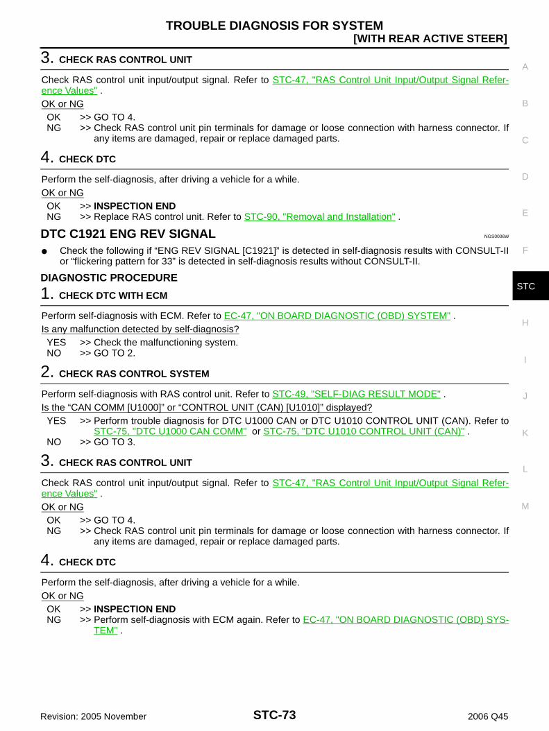
TROUBLE DIAGNOSIS FOR SYSTEM
STC-73
[WITH REAR ACTIVE STEER]
C
D
E
F
H
I
J
K
L
M
A
B
STC
Revision: 2005 November 2006 Q45
3. CHECK RAS CONTROL UNIT
Check RAS control unit input/output signal. Refer to STC-47, "RAS Control Unit Input/Output Signal Refer-ence Values" .OK or NGOK >> GO TO 4.NG >> Check RAS control unit pin terminals for damage or loose connection with harness connector. If
any items are damaged, repair or replace damaged parts.
4. CHECK DTC
Perform the self-diagnosis, after driving a vehicle for a while.OK or NGOK >> INSPECTION ENDNG >> Replace RAS control unit. Refer to STC-90, "Removal and Installation" .
DTC C1921 ENG REV SIGNAL NGS0006W
Check the following if “ENG REV SIGNAL [C1921]” is detected in self-diagnosis results with CONSULT-IIor “flickering pattern for 33” is detected in self-diagnosis results without CONSULT-II.
DIAGNOSTIC PROCEDURE
1. CHECK DTC WITH ECM
Perform self-diagnosis with ECM. Refer to EC-47, "ON BOARD DIAGNOSTIC (OBD) SYSTEM" .Is any malfunction detected by self-diagnosis?YES >> Check the malfunctioning system.NO >> GO TO 2.
2. CHECK RAS CONTROL SYSTEM
Perform self-diagnosis with RAS control unit. Refer to STC-49, "SELF-DIAG RESULT MODE" .Is the “CAN COMM [U1000]” or “CONTROL UNIT (CAN) [U1010]” displayed?YES >> Perform trouble diagnosis for DTC U1000 CAN or DTC U1010 CONTROL UNIT (CAN). Refer to
STC-75, "DTC U1000 CAN COMM" or STC-75, "DTC U1010 CONTROL UNIT (CAN)" .NO >> GO TO 3.
3. CHECK RAS CONTROL UNIT
Check RAS control unit input/output signal. Refer to STC-47, "RAS Control Unit Input/Output Signal Refer-ence Values" .OK or NGOK >> GO TO 4.NG >> Check RAS control unit pin terminals for damage or loose connection with harness connector. If
any items are damaged, repair or replace damaged parts.
4. CHECK DTC
Perform the self-diagnosis, after driving a vehicle for a while.OK or NGOK >> INSPECTION ENDNG >> Perform self-diagnosis with ECM again. Refer to EC-47, "ON BOARD DIAGNOSTIC (OBD) SYS-
TEM" .

STC-74
[WITH REAR ACTIVE STEER]TROUBLE DIAGNOSIS FOR SYSTEM
Revision: 2005 November 2006 Q45
DTC C1929 VDC NGS0008N
Check the following if “VDC [C1929]” is detected in self-diagnosis results with CONSULT-II or “flickeringpattern for 26” is detected in self-diagnosis results without CONSULT-II.
DIAGNOSTIC PROCEDURE
1. CHECK DTC WITH VDC/TCS/ABS CONTROL UNIT
Perform self-diagnosis with VDC/TCS/ABS control unit. Refer to BRC-24, "SELF-DIAG RESULT MODE" .Is any malfunction detected by self-diagnosis?YES >> Check the malfunctioning system.NO >> GO TO 2.
2. CHECK RAS CONTROL SYSTEM
Perform self-diagnosis with RAS control unit. Refer to STC-49, "SELF-DIAG RESULT MODE" .Is the “CAN COMM [U1000]” or “CONTROL UNIT (CAN) [U1010]” displayed?YES >> Perform trouble diagnosis for DTC U1000 CAN or DTC U1010 CONTROL UNIT (CAN). Refer to
STC-75, "DTC U1000 CAN COMM" or STC-75, "DTC U1010 CONTROL UNIT (CAN)" .NO >> GO TO 3.
3. CHECK RAS CONTROL UNIT
Check RAS control unit input/output signal. Refer to STC-47, "RAS Control Unit Input/Output Signal Refer-ence Values" .OK or NGOK >> GO TO 4.NG >> Check RAS control unit pin terminals for damage or loose connection with harness connector. If
any items are damaged, repair or replace damaged parts.
4. CHECK DTC
Perform the self-diagnosis, after driving a vehicle for a while.OK or NGOK >> INSPECTION ENDNG >> Perform self-diagnosis with VDC/TCS/ABS control unit again. Refer to BRC-24, "SELF-DIAG
RESULT MODE" .

TROUBLE DIAGNOSIS FOR SYSTEM
STC-75
[WITH REAR ACTIVE STEER]
C
D
E
F
H
I
J
K
L
M
A
B
STC
Revision: 2005 November 2006 Q45
DTC U1000 CAN COMM NGS0008O
Check the following if “CAN COMM [U1000]” is detected in self-diagnosis results with CONSULT-II.
DIAGNOSTIC PROCEDURE
1. CHECK CAN COMMUNICATION CIRCUIT
With CONSULT-II1. Turn ignition switch “ON” and start engine.2. Select “SELF-DIAG RESULTS” mode for “RAS/HICAS” within CONSULT-II.3. Perform the self-diagnosis.Is the “CAN COMM CIRCUIT [U1000]” displayed?YES >> Print out CONSULT-II screen and go to LAN-17, "Pre-
cautions When Using CONSULT-II" .NO >> INSPECTION END
DTC U1010 CONTROL UNIT (CAN) NGS0008P
Check the following if “CONTROL UNIT (CAN) [U1010]” is detected in self-diagnosis results with CON-SULT-II.
DIAGNOSTIC PROCEDURE
1. CHECK CAN COMMUNICATION CIRCUIT
With CONSULT-II1. Turn ignition switch “ON” and start engine.2. Select “SELF-DIAG RESULTS” mode for “RAS/HICAS” within CONSULT-II.3. Perform the self-diagnosis.Is the “CAN COMM CIRCUIT [U1010]” displayed?YES >> GO TO 2.NO >> INSPECTION END
2. PERFORM SELF-DIAGNOSIS
With CONSULT-II1. Turn ignition switch “ON”. (Do not start engine.)2. Select “SELF-DIAG RESULTS” mode for “RAS/HICAS” with CONSULT-II.3. Touch “ERASE”.4. Turn ignition switch “OFF” and wait at least 10 seconds.5. Perform the self-diagnosis, after driving a vehicle for a while.Is the “U1010 CONTROL UNIT (CAN)” displayed?YES >> Replace RAS control unit. Refer to STC-90, "Removal and Installation" .NO >> INSPECTION END
SDIA1850E
SGIA1488E

STC-76
[WITH REAR ACTIVE STEER]TROUBLE DIAGNOSIS FOR SYSTEM
Revision: 2005 November 2006 Q45
RAS Actuator Assembly NGS0008X
DIAGNOSTIC PROCEDURE
1. CHECK (1): RAS ACTUATOR ASSEMBLY STROKE
Perform CONSULT-II “ACTIVE TEST”, and then check the RASactuator assembly stroke “S” when turning the steering wheel clock-wise or counterclockwise by 180° or more. Refer to STC-52, "Opera-tion Procedure" .
OK or NGOK >> GO TO 2.NG >> GO TO 3.
2. CHECK (2): RAS ACTUATOR ASSEMBLY STROKE
Perform CONSULT-II “ACTIVE TEST“. When turning the steeringwheel in neutral position “N”, the rear wheel turns clockwise/counter-clockwise periodically. At that time, check RAS actuator assemblystroke “S”. Refer to STC-52, "Operation Procedure" .
OK or NGOK >> INSPECTION ENDNG >> GO TO 3.
3. CHECK RAS MOTOR
Check RAS motor. Refer to STC-82, "RAS MOTOR" .OK or NGOK >> GO TO 4.NG >> Check the RAS actuator assembly stroke again after replacing.
4. CHECK REAR WHEEL STEERING ANGLE SENSOR
Check rear wheel steering angle sensor. Refer to STC-83, "REAR WHEEL STEERING ANGLE SENSOR" .OK or NGOK >> GO TO 5.NG >> Rear wheel steering angle sensor malfunction. Check the stroke again after replacing.
5. CHECK (1): RAS ACTUATOR ASSEMBLY STROKE AGAIN
Check RAS actuator assembly stroke again after checking rear suspension components.OK or NGOK >> GO TO 6.NG >> RAS actuator assembly is malfunctioning. Replace RAS actuator assembly.
RAS actuator stroke “S”: 2.8 – 3.0 mm (0.110 – 0.118 in)
SGIA1601E
RAS actuator stroke “S”: 2.3 – 2.5 mm (0.091 – 0.098 in)
SGIA1601E

TROUBLE DIAGNOSIS FOR SYSTEM
STC-77
[WITH REAR ACTIVE STEER]
C
D
E
F
H
I
J
K
L
M
A
B
STC
Revision: 2005 November 2006 Q45
6. CHECK RAS CONTROL UNIT
Check RAS control unit input/output signal. Refer to STC-47, "RAS Control Unit Input/Output Signal Refer-ence Values" .OK or NGOK >> GO TO 7.NG >> Check RAS control unit pin terminals for damage or loose connection with harness connector. If
any items are damaged, repair or replace damaged parts.
7. CHECK (2): RAS ACTUATOR ASSEMBLY STROKE AGAIN
Check RAS actuator assembly stroke again.OK or NGOK >> INSPECTION ENDNG >> Replace RAS control unit. Refer to STC-90, "Removal and Installation" .
Power Steering Solenoid Valve NGS0006V
CONSULT-II REFERENCE VALUE IN DATA MONITOR MODEData are reference value.
RAS CONTROL UNIT TERMINALS AND REFERENCE VALUEData are reference value and are measured between each terminal and ground.
CAUTION:When using a circuit tester to measure voltage for inspection, be sure not to extend forcibly any connector terminal.
Monitored item Content Condition Display value
POWER STR SOL [A]Monitored value of current at power steering solenoid valve
Vehicle speed: 0 km/h (0 MPH)(Engine is running)
Approx. 1.10 A
Vehicle speed: 100 km/h (62 MPH) Approx. 0.54 A
TerminalWire color
Item Condition Data (Approx.)
36 LG Power steering solenoid valve
Vehicle speed: 0 km/h (0 MPH)(Engine is running)
4.4 - 6.6 V
Vehicle speed: 100 km/h (62 MPH) 2.4 - 3.6 V

STC-78
[WITH REAR ACTIVE STEER]TROUBLE DIAGNOSIS FOR SYSTEM
Revision: 2005 November 2006 Q45
DIAGNOSTIC PROCEDURE
1. CHECK POWER STEERING SOLENOID VALVE SIGNAL
With CONSULT-II1. Start engine.2. Select “DATA MONITOR” mode for “RAS/HICAS” with CONSULT-II.3. Read out the value of “POWER STR SOL”.
Without CONSULT-II1. Start engine.2. Check signal between RAS control unit harness connector (A)
terminal and ground.
OK or NGOK >> GO TO 5.NG >> GO TO 2.
2. CHECK POWER STEERING SOLENOID VALVE GROUND CIRCUIT
1. Turn ignition switch “OFF”.2. Disconnect power steering solenoid valve harness connector.3. Check continuity between power steering solenoid valve har-
ness connector (A) F3 terminal 2 and ground.
Also check harness for short to power. OK or NG OK >> GO TO 3. NG >> Repair or replace damaged parts.
Condition Display value
Vehicle speed: 0 km/h (0 MPH)(Engine is running)
Approx. 1.10 A
Vehicle speed: 100 km/h (62 MPH) Approx. 0.54 A
SGIA1405E
Connector Terminal ConditionData
(Approx.)
B39 36 -
Ground
Vehicle speed: 0 km/h (0 MPH)(Engine is running)
4.4 - 6.6 V
Vehicle speed: 100 km/h (62 MPH) 2.4 - 3.6 V
SGIA1489E
Continuity should exist.
SGIA1411E

TROUBLE DIAGNOSIS FOR SYSTEM
STC-79
[WITH REAR ACTIVE STEER]
C
D
E
F
H
I
J
K
L
M
A
B
STC
Revision: 2005 November 2006 Q45
3. CHECK POWER STEERING SOLENOID VALVE
1. Turn ignition switch “OFF”.2. Disconnect power steering solenoid valve harness connector.3. Check resistance between power steering solenoid valve con-
nector (A) terminals 1 and 2.
4. Check power steering solenoid valve connector (A) by listeningfor its operation sound while applying battery voltage to powersteering solenoid valve connector (A) terminals 1 (positive) and2 (negative).
OK or NG OK >> GO TO 4. NG >> Replace power steering solenoid valve. Refer to PS-17,
"COMPONENT" .
4. CHECK HARNESS BETWEEN RAS CONTROL UNIT AND POWER STEERING SOLENOID VALVE
1. Turn ignition switch “OFF”.2. Disconnect RAS control unit harness connector and power steering solenoid valve harness connector.3. Check continuity between RAS control unit harness connector
(A) B39 terminal 36 and power steering solenoid valve harnessconnector (B) F3 terminal 1.
Also check harness for short to ground and short to power.OK or NGOK >> GO TO 5.NG >> Repair or replace damaged parts.
5. CHECK RAS CONTROL UNIT
Check RAS control unit input/output signal. Refer to STC-47, "RAS Control Unit Input/Output Signal Refer-ence Values" .OK or NGOK >> GO TO 6.NG >> Check RAS control unit pin terminals for damage or loose connection with harness connector. If
any item is damaged, repair or replace damaged parts.
1 - 2 : Approx. 4 - 6 Ω
SGIA1412E
SGIA1419E
Continuity should exist.
SGIA1490E

STC-80
[WITH REAR ACTIVE STEER]TROUBLE DIAGNOSIS FOR SYSTEM
Revision: 2005 November 2006 Q45
6. CHECK STEERING WHEEL TURNING FORCE
Check steering wheel turning force. Refer to PS-8, "STEERING WHEEL TURNING FORCE" .OK or NGOK >> INSPECTION ENDNG >> Check relief oil pressure of power steering oil pump and power steering gear. If any item is dam-
aged, repair or replace damaged parts. Refer to PS-26, "RELIEF OIL PRESSURE" (power steer-ing oil pump) and PS-28, "Disassembly and Assembly" (power steering gear).
Stop Lamp Switch NGS0008Q
CONSULT-II REFERENCE VALUE IN DATA MONITOR MODEData are reference value.
RAS CONTROL UNIT TERMINALS AND REFERENCE VALUEData are reference value and are measured between each terminal and ground.
CAUTION:When using a circuit tester to measure voltage for inspection, be sure not to extend forcibly any connector terminal.
DIAGNOSTIC PROCEDURE
1. CHECK STOP LAMP SIGNAL
With CONSULT-II1. Start engine.2. Select “DATA MONITOR” mode for “RAS/HICAS” with CONSULT-II.3. Read out the value of “STOP LAMP SW”.
Without CONSULT-II1. Start engine.2. Check signal between RAS control unit harness connector (A)
terminal and ground.
OK or NGOK >> GO TO 5.NG >> GO TO 2.
Monitored item Content Condition Display value
STOP LAMP SW [ON/OFF] Stop lamp conditionBrake pedal: Depressed ON
Brake pedal: Released OFF
TerminalWire color
Item Condition Data (Approx.)
22 L/B Stop lamp switchBrake pedal: Depressed Battery voltage
Brake pedal: Released 0 V
Condition Display value
Brake pedal: Depressed ON
Brake pedal: Released OFF
SGIA1491E
Connector Terminal Condition Data (Approx.)
B39 22 -
Ground
Brake pedal: Depressed Battery voltage
Brake pedal: Released 0 V
SGIA1492E

TROUBLE DIAGNOSIS FOR SYSTEM
STC-81
[WITH REAR ACTIVE STEER]
C
D
E
F
H
I
J
K
L
M
A
B
STC
Revision: 2005 November 2006 Q45
2. CHECK STOP LAMP SWITCH POWER SUPPLY CIRCUIT
1. Turn ignition switch “OFF”.2. Disconnect stop lamp switch harness connector.3. Turn ignition switch “ON”. (Do not start engine.)4. Check voltage between stop lamp switch harness connector (A)
M402 terminal 3 and ground.
OK or NGOK >> GO TO 3.NG >> Check the following. If any items are damaged, repair or
replace damaged parts. 10A fuse [No. 17, located in the fuse block (J/B)
No.1]. Refer to PG-2, "POWER SUPPLY ROUTING" . Harness for short or open between battery and stop lamp switch harness connector M402 ter-
minal 3.
3. CHECK HARNESS BETWEEN RAS CONTROL UNIT AND STOP LAMP SWITCH
1. Turn ignition switch “OFF”.2. Disconnect RAS control unit harness connector and stop lamp switch harness connector.3. Check continuity between RAS control unit harness connector
(A) B39 terminal 22 and stop lamp switch harness connector (B)M402 terminal 4.
Also check harness for short to ground and short to power.OK or NGOK >> GO TO 4.NG >> Repair or replace damaged parts.
4. CHECK STOP LAMP SWITCH
1. Turn ignition switch “OFF”.2. Disconnect stop lamp switch harness connector.3. Remove stop lamp switch.4. Push and release stop lamp switch and check continuity
between stop lamp switch connector (A) M402 terminals 3 and4.
OK or NGOK >> GO TO 5.NG >> Replace back-up lamp switch.
Connector Terminal Voltage (Approx.)
M402 3 - Ground Battery voltage
SGIA1493E
Continuity should exist.
SGIA1495E
Terminal Condition Continuity
3 - 4Push stop lamp switch Yes
Release stop switch No
SGIA1497E

STC-82
[WITH REAR ACTIVE STEER]TROUBLE DIAGNOSIS FOR SYSTEM
Revision: 2005 November 2006 Q45
5. CHECK RAS CONTROL UNIT
Check RAS control unit input/output signal. Refer to STC-47, "RAS Control Unit Input/Output Signal Refer-ence Values" .OK or NGOK >> INSPECTION ENDNG >> Check RAS control unit pin terminals for damage or loose connection with harness connector. If
any items are damaged, repair or replace damaged parts.
Component Inspection NGS000CU
RAS MOTOR1. Turn ignition switch “OFF”.2. Disconnect RAS motor harness connector.3. Remove RAS motor. Refer to STC-92, "COMPONENTS" .4. Check operation by supply 6 V (B) voltage to RAS motor con-
nector (A) terminals 1 and 2.CAUTION: Never supply 12 V voltage (battery, etc.) to the RAS
motor. Never operate RAS motor for more than 1 second. Be careful not to overheat the harness.
5. Check continuity between RAS motor connector (A) B82 termi-nals 1 and 2.
6. If NG, replace the RAS motor.
RAS MOTOR RELAY1. Turn ignition switch “OFF”.2. Remove RAS motor relay. Refer to STC-41, "Component Parts Location" .3. Apply 12 V direct current between RAS motor relay connector
B42 terminals 1 and 2.4. Check continuity between RAS motor relay connector B42 ter-
minals 3 and 5.
5. Check continuity between RAS motor relay connector B42 ter-minals 1 and 2.
6. If NG, replace the RAS motor relay.
Terminal Actuator motor
1 (Positive) - 2 (Negative) Clockwise rotate
2 (Positive) - 1 (Negative) Counterclockwise rotate
1 – 2 : Approx. 0.45 Ω
SGIA1473E
SGIA1474E
Terminal Condition Continuity
3 - 51 2 V direct current supply between terminals 1 and 2 Yes
OFF No
1 – 2 : 74 ΩSGIA1286E

TROUBLE DIAGNOSIS FOR SYSTEM
STC-83
[WITH REAR ACTIVE STEER]
C
D
E
F
H
I
J
K
L
M
A
B
STC
Revision: 2005 November 2006 Q45
NOISE SUPPRESSOR1. Turn ignition switch “OFF”.2. Remove noise suppressor. Refer to STC-41, "Component Parts Location" .3. Check noise suppressor connector (A) continuity between the
following terminals.
4. If NG, replace the noise suppressor.
REAR WHEEL STEERING ANGLE SENSOR1. Turn ignition switch “OFF”.2. Disconnect rear wheel steering angle sensor harness connector.3. Remove rear wheel steering angle sensor. 4. Check resistance between rear wheel steering angle sensor
connector (A) B81 terminals 1 and 3.
5. While turning the rear wheel steering angle sensor clockwise orcounterclockwise, check rear wheel steering angle sensor con-nector (A) B81 terminals 1 and 2, 4.
6. When replacing rear wheel steering angle sensor, perform theneutral position adjustment after replacing rear wheel steeringangle sensor. Refer toSTC-92, "Neutral Position" .
1 – 3 : Continuity should exist.1 – 2 : Continuity should no exist.1 – 4 : Continuity should no exist.2 – 1 : Continuity should no exist.2 – 3 : Continuity should no exist.2 – 4 : Continuity should exist.
SGIA1467E
1 - 3 : 1 kΩ
SGIA1485E
1 - 2 : 1.2 k – 1.5 kΩ1 - 4 : 1.2 k – 1.5 kΩ
SGIA1486E

STC-84
[WITH REAR ACTIVE STEER]TROUBLE DIAGNOSIS FOR SYSTEM
Revision: 2005 November 2006 Q45
POWER STEERING SOLENOID VALVE1. Turn ignition switch “OFF”.2. Disconnect power steering solenoid valve harness connector.3. Check resistance between power steering solenoid valve con-
nector (A) terminals 1 and 2.
4. Check power steering solenoid valve connector (A) by listeningfor its operation sound while applying battery voltage to powersteering solenoid valve connector (A) terminals 1 (positive) and2 (negative).
5. If NG, replace power steering solenoid valve.
STOP LAMP SWITCH1. Turn ignition switch “OFF”.2. Disconnect stop lamp switch harness connector.3. Remove stop lamp switch.4. Push and release stop lamp switch and check continuity
between stop lamp switch connector (A) M402 terminals 3 and4.
5. If NG, replace stop lamp switch.
1 - 2 : Approx. 4 - 6 Ω
SGIA1412E
SGIA1419E
Terminal Condition Continuity
3 - 4Push stop lamp switch Yes
Release stop switch No
SGIA1497E

TROUBLE DIAGNOSIS FOR SYMPTOMS
STC-85
[WITH REAR ACTIVE STEER]
C
D
E
F
H
I
J
K
L
M
A
B
STC
Revision: 2005 November 2006 Q45
TROUBLE DIAGNOSIS FOR SYMPTOMS PFP:00007
RAS Warning Lamp Does Not Turn ON for Approx. 1 Second When The Igniting Switch Is Turned to ON NGS0008S
DIAGNOSTIC PROCEDURE
1. CHECK SYSTEM FOR POWER SUPPLY CIRCUIT
Perform trouble diagnosis for power supply circuit. Refer to STC-60, "DTC C1909 CONTROL UNIT" .OK or NGOK >> GO TO 2.NG >> Repair or replace damaged parts.
2. CHECK SYSTEM FOR RAS CONTROL UNIT
Perform trouble diagnosis for RAS control unit. Refer to STC-56, "DTC C1900, C1901, C1905, C1906, C1907,C1908, C1922, C1927, C1928 CONTROL UNIT" .OK or NGOK >> GO TO 3.NG >> Repair or replace damaged parts.
3. CHECK COMBINATION METER POWER SUPPLY CIRCUIT
1. Turn ignition switch “OFF”.2. Disconnect combination meter harness connector.3. Check voltage between combination meter harness connector
(A) terminal and ground.
4. Turn ignition switch “ON”. (Do not start engine.)5. Check voltage between combination meter harness connector
(A) terminal and ground.
OK or NGOK >> GO TO 4.NG >> Check the following. If any items are damaged, repair or
replace damaged parts. 10A fuse [No. 9, located in the fuse block (J/B) No.1].
Refer to PG-2, "POWER SUPPLY ROUTING" . Harness for short or open between ignition switch and combination meter harness connector
M43 terminal 59. Ignition switch. Refer to PG-2, "POWER SUPPLY ROUTING" .
Connector Terminal Voltage (Approx.)
M43 59 - Ground 0 V
SGIA1501E
Connector Terminal Voltage (Approx.)
M43 59 - Ground Battery voltage
SGIA1502E

STC-86
[WITH REAR ACTIVE STEER]TROUBLE DIAGNOSIS FOR SYMPTOMS
Revision: 2005 November 2006 Q45
4. CHECK HARNESS BETWEEN RAS CONTROL UNIT AND COMBINATION METER
1. Turn ignition switch “OFF”.2. Disconnect RAS control unit harness connector and combination meter harness connector.3. Check continuity between RAS control unit harness connector
(A) B39 terminal 26 and combination meter harness connector(B) M43 terminal 55.
Also check harness for short to power.OK or NGOK >> GO TO 5.NG >> Repair or replace damaged parts.
5. CHECK RAS WARNING LAMP
1. Turn ignition switch “OFF”.2. Connect combination meter harness connector.3. Disconnect RAS control unit harness connector.4. Turn ignition switch “ON”. (Do not start engine.)5. Ground the following terminal using suitable wiring.– RAS control unit harness connector (A) B39 terminal 26 and
ground.Does RAS warning lamp turn on?OK >> GO TO 6.NG >> Replace combination meter. Refer to DI-23, "Removal
and Installation for Combination Meter" .
6. CHECK RAS CONTROL UNIT
Check RAS control unit input/output signal. Refer to STC-47, "RAS Control Unit Input/Output Signal Refer-ence Values" .OK or NGOK >> GO TO 7.NG >> Check RAS control unit pin terminals for damage or loose connection with harness connector. If
any items are damaged, repair or replace damaged parts.
7. CHECK SYMPTOM
Check again.OK or NGOK >> INSPECTION ENDNG >> Replace RAS control unit. Refer to STC-90, "Removal and Installation" .
Continuity should exist.
SGIA1503E
SGIA1504E

TROUBLE DIAGNOSIS FOR SYMPTOMS
STC-87
[WITH REAR ACTIVE STEER]
C
D
E
F
H
I
J
K
L
M
A
B
STC
Revision: 2005 November 2006 Q45
The Steering Force of Steering Wheel Is Not Changed Smoothly According to the Vehicle Speed NGS00093
SYMPTOM:The steering force does not change smoothly according to the vehicle speed (Heavy steering forcewith the vehicle stopped/Light handle operation during high-speed driving).
DIAGNOSTIC PROCEDURE
1. CHECK SYSTEM FOR VEHICLE SPEED SENSOR
Perform trouble diagnosis for vehicle speed sensor system. Refer to STC-72, "DTC C1919 VEHICLE SPEEDSEN" .OK or NGOK >> GO TO 2.NG >> Repair or replace damaged parts.
2. CHECK SYSTEM FOR STOP LAMP SWITCH
Perform trouble diagnosis for stop lamp switch. Refer to STC-80, "Stop Lamp Switch" .OK or NGOK >> GO TO 3.NG >> Repair or replace damaged parts.
3. CHECK SYSTEM FOR POWER STEERING SOLENOID VALVE
Perform trouble diagnosis for power steering solenoid valve system. Refer to STC-77, "Power Steering Sole-noid Valve" .OK or NGOK >> GO TO 4.NG >> Repair or replace damaged parts.
4. CHECK SYSTEM FOR RAS ACTUATOR ASSEMBLY
Perform trouble diagnosis for RAS actuator assembly system. Refer to STC-76, "RAS Actuator Assembly" .OK or NGOK >> GO TO 4.NG >> Repair or replace damaged parts.
5. CHECK RAS CONTROL UNIT
Check RAS control unit input/output signal. Refer to STC-47, "RAS Control Unit Input/Output Signal Refer-ence Values" .OK or NGOK >> GO TO 6.NG >> Check RAS control unit pin terminals for damage or loose connection with harness connector. If
any items are damaged, repair or replace damaged parts.
6. CHECK SYMPTOM
Check again.OK or NGOK >> INSPECTION ENDNG >> Replace RAS control unit. Refer to STC-90, "Removal and Installation" .

STC-88
[WITH REAR ACTIVE STEER]TROUBLE DIAGNOSIS FOR SYMPTOMS
Revision: 2005 November 2006 Q45
Hard Steering When Fully Turning the Steering Wheel NGS0008Y
DIAGNOSTIC PROCEDURE
1. CHECK SYSTEM FOR VEHICLE SPEED SENSOR
Perform trouble diagnosis for vehicle speed sensor system. Refer to STC-72, "DTC C1919 VEHICLE SPEEDSEN" .OK or NGOK >> GO TO 2.NG >> Repair or replace damaged parts.
2. CHECK SYSTEM FOR STOP LAMP SWITCH
Perform trouble diagnosis for stop lamp switch. Refer to STC-80, "Stop Lamp Switch" .OK or NGOK >> GO TO 3.NG >> Repair or replace damaged parts.
3. CHECK SYSTEM FOR POWER STEERING SOLENOID VALVE
Perform trouble diagnosis for power steering solenoid valve system. Refer to STC-77, "Power Steering Sole-noid Valve" .OK or NGOK >> GO TO 4.NG >> Repair or replace damaged parts.
4. CHECK RAS CONTROL UNIT
Check RAS control unit input/output signal. Refer to STC-47, "RAS Control Unit Input/Output Signal Refer-ence Values" .OK or NGOK >> GO TO 5.NG >> Check RAS control unit pin terminals for damage or loose connection with harness connector. If
any items are damaged, repair or replace damaged parts.
5. CHECK SYMPTOM
Check again.OK or NGOK >> INSPECTION ENDNG >> Replace RAS control unit. Refer to STC-90, "Removal and Installation" .

TROUBLE DIAGNOSIS FOR SYMPTOMS
STC-89
[WITH REAR ACTIVE STEER]
C
D
E
F
H
I
J
K
L
M
A
B
STC
Revision: 2005 November 2006 Q45
Light Steering When Driving at a High Speed NGS0008Z
DIAGNOSTIC PROCEDURE
1. CHECK SYSTEM FOR VEHICLE SPEED SENSOR
Perform trouble diagnosis for vehicle speed sensor system. Refer to STC-72, "DTC C1919 VEHICLE SPEEDSEN" .OK or NGOK >> GO TO 2.NG >> Repair or replace damaged parts.
2. CHECK SYSTEM FOR POWER STEERING SOLENOID VALVE
Perform trouble diagnosis for power steering solenoid valve system. Refer to STC-77, "Power Steering Sole-noid Valve" .OK or NGOK >> GO TO 3.NG >> Repair or replace damaged parts.
3. CHECK RAS CONTROL UNIT
Check RAS control unit input/output signal. Refer to STC-47, "RAS Control Unit Input/Output Signal Refer-ence Values" .OK or NGOK >> GO TO 4.NG >> Check RAS control unit pin terminals for damage or loose connection with harness connector. If
any items are damaged, repair or replace damaged parts.
4. CHECK SYMPTOM
Check again.OK or NGOK >> INSPECTION ENDNG >> Replace RAS control unit. Refer to STC-90, "Removal and Installation" .

STC-90
[WITH REAR ACTIVE STEER]CONTROL UNIT
Revision: 2005 November 2006 Q45
CONTROL UNIT PFP:28400
Removal and Installation NGS0006Y
REMOVAL1. Turn the ignition switch OFF and disconnect the battery cable from the negative terminal.2. Remove the trunk side finisher. Refer to EI-60, "Removal and Installation" .3. Disconnect the RAS control unit connector.4. Remove the RAS control unit bolts.5. Remove the RAS control unit (1).
INSTALLATIONNote the following, and installation is the reverse order of removal. When installing the RAS control unit, tighten bolts to the specified torque.
SGIA1422E
RAS control unit bolts : 8.3 N·m (0.85 kg-m, 73 in-lb)

REAR ACTIVE STEER
STC-91
[WITH REAR ACTIVE STEER]
C
D
E
F
H
I
J
K
L
M
A
B
STC
Revision: 2005 November 2006 Q45
REAR ACTIVE STEER PFP:55705
Removal and Installation NGS0004K
COMPONENTS
REMOVAL1. Remove center muffler with power tool. Refer to EX-3, "Removal and Installation" .2. Remove coil spring. Refer to RSU-16, "Removal and Installation" .
NOTE:Put the adjustment position marks of wheel alignment on the adjusting bolts and decenter cam.
3. Disconnect each harness connectors from RAS actuator assembly and rear suspension member.4. Remove fixing bolts and nuts of RAS actuator assembly (1), and
then remove RAS actuator assembly (1) from rear suspensionmember.
INSTALLATIONNote the following, and installation is the reverse order of removal. Refer to STC-91, "COMPONENTS" about each tightening torque. When installing RAS actuator assembly to rear suspension member, check the mounting surfaces of RAS
actuator assembly and rear suspension member for oil, dirt, sand, or other foreign materials. Adjust rear wheel alignment. Refer to RSU-5, "Wheel Alignment Inspection" .
1. Adjust bolt 2. RAS actuator assembly 3. Rear lower link
4. Decenter cam
Refer to GI-9, "Components" , for the symbols in the figure.
SGIA1505E
SGIA1506E
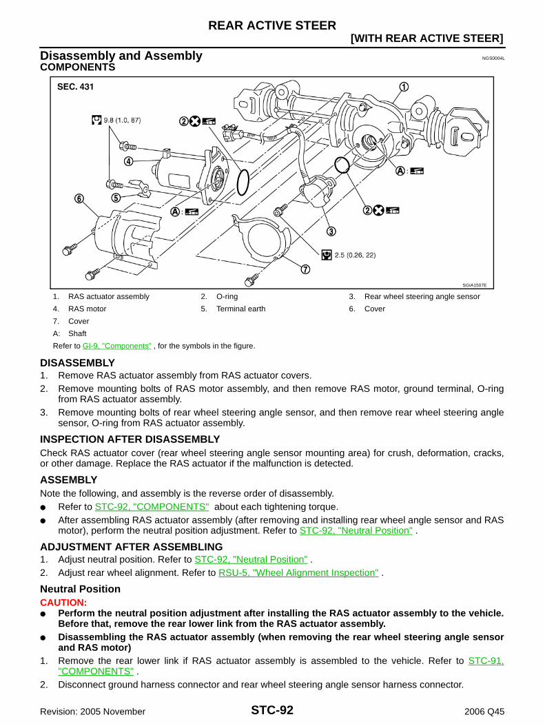
STC-92
[WITH REAR ACTIVE STEER]REAR ACTIVE STEER
Revision: 2005 November 2006 Q45
Disassembly and Assembly NGS0004L
COMPONENTS
DISASSEMBLY1. Remove RAS actuator assembly from RAS actuator covers.2. Remove mounting bolts of RAS motor assembly, and then remove RAS motor, ground terminal, O-ring
from RAS actuator assembly.3. Remove mounting bolts of rear wheel steering angle sensor, and then remove rear wheel steering angle
sensor, O-ring from RAS actuator assembly.
INSPECTION AFTER DISASSEMBLYCheck RAS actuator cover (rear wheel steering angle sensor mounting area) for crush, deformation, cracks,or other damage. Replace the RAS actuator if the malfunction is detected.
ASSEMBLYNote the following, and assembly is the reverse order of disassembly. Refer to STC-92, "COMPONENTS" about each tightening torque. After assembling RAS actuator assembly (after removing and installing rear wheel angle sensor and RAS
motor), perform the neutral position adjustment. Refer to STC-92, "Neutral Position" .
ADJUSTMENT AFTER ASSEMBLING1. Adjust neutral position. Refer to STC-92, "Neutral Position" .2. Adjust rear wheel alignment. Refer to RSU-5, "Wheel Alignment Inspection" .
Neutral PositionCAUTION: Perform the neutral position adjustment after installing the RAS actuator assembly to the vehicle.
Before that, remove the rear lower link from the RAS actuator assembly. Disassembling the RAS actuator assembly (when removing the rear wheel steering angle sensor
and RAS motor)1. Remove the rear lower link if RAS actuator assembly is assembled to the vehicle. Refer to STC-91,
"COMPONENTS" .2. Disconnect ground harness connector and rear wheel steering angle sensor harness connector.
1. RAS actuator assembly 2. O-ring 3. Rear wheel steering angle sensor
4. RAS motor 5. Terminal earth 6. Cover
7. Cover
A: Shaft
Refer to GI-9, "Components" , for the symbols in the figure.
SGIA1507E
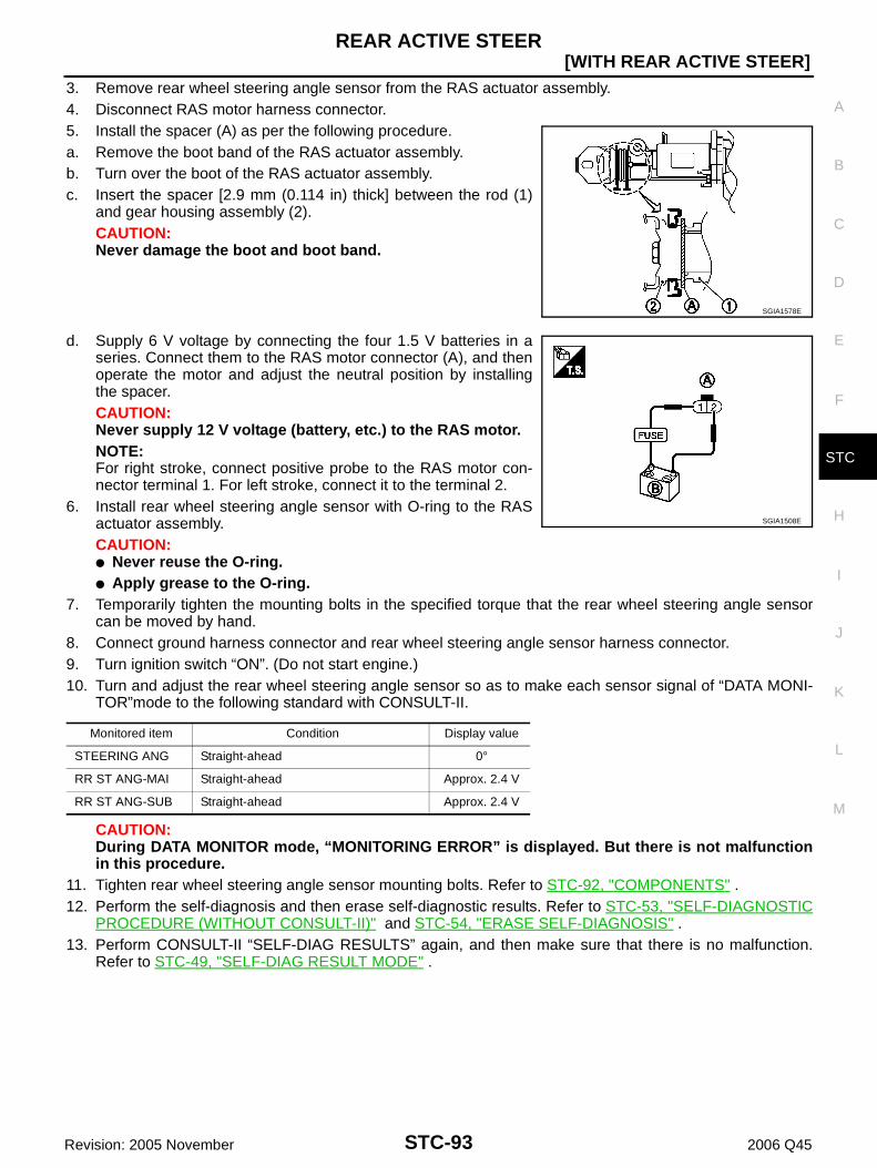
REAR ACTIVE STEER
STC-93
[WITH REAR ACTIVE STEER]
C
D
E
F
H
I
J
K
L
M
A
B
STC
Revision: 2005 November 2006 Q45
3. Remove rear wheel steering angle sensor from the RAS actuator assembly.4. Disconnect RAS motor harness connector.5. Install the spacer (A) as per the following procedure.a. Remove the boot band of the RAS actuator assembly.b. Turn over the boot of the RAS actuator assembly.c. Insert the spacer [2.9 mm (0.114 in) thick] between the rod (1)
and gear housing assembly (2).CAUTION:Never damage the boot and boot band.
d. Supply 6 V voltage by connecting the four 1.5 V batteries in aseries. Connect them to the RAS motor connector (A), and thenoperate the motor and adjust the neutral position by installingthe spacer.CAUTION:Never supply 12 V voltage (battery, etc.) to the RAS motor.NOTE:For right stroke, connect positive probe to the RAS motor con-nector terminal 1. For left stroke, connect it to the terminal 2.
6. Install rear wheel steering angle sensor with O-ring to the RASactuator assembly.CAUTION: Never reuse the O-ring. Apply grease to the O-ring.
7. Temporarily tighten the mounting bolts in the specified torque that the rear wheel steering angle sensorcan be moved by hand.
8. Connect ground harness connector and rear wheel steering angle sensor harness connector.9. Turn ignition switch “ON”. (Do not start engine.)10. Turn and adjust the rear wheel steering angle sensor so as to make each sensor signal of “DATA MONI-
TOR”mode to the following standard with CONSULT-II.
CAUTION:During DATA MONITOR mode, “MONITORING ERROR” is displayed. But there is not malfunctionin this procedure.
11. Tighten rear wheel steering angle sensor mounting bolts. Refer to STC-92, "COMPONENTS" .12. Perform the self-diagnosis and then erase self-diagnostic results. Refer to STC-53, "SELF-DIAGNOSTIC
PROCEDURE (WITHOUT CONSULT-II)" and STC-54, "ERASE SELF-DIAGNOSIS" .13. Perform CONSULT-II “SELF-DIAG RESULTS” again, and then make sure that there is no malfunction.
Refer to STC-49, "SELF-DIAG RESULT MODE" .
SGIA1578E
Monitored item Condition Display value
STEERING ANG Straight-ahead 0°
RR ST ANG-MAI Straight-ahead Approx. 2.4 V
RR ST ANG-SUB Straight-ahead Approx. 2.4 V
SGIA1508E

STC-94
[WITH REAR ACTIVE STEER]REAR ACTIVE STEER
Revision: 2005 November 2006 Q45