materials for high pressure fuel injection systems€¦ · · 2011-05-25materials for high...
TRANSCRIPT

1 Managed by UT-Battellefor the U.S. Department of Energy
Materials for High Pressure Fuel Injection Systems
Peter J. Blau1 and Nan Yang2
Principal Investigators
(1) Oak Ridge National Laboratory, TN(2) Caterpillar® Inc., Peoria, IL
POSTER PRESENTATION: May 10, 2011
Project ID: PM021
This poster does not contain any proprietary, confidential, or otherwise restricted information
2 Managed by UT-Battellefor the U.S. Department of Energy
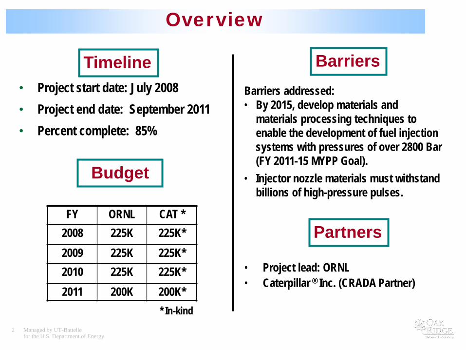
Overview
• Project start date: July 2008• Project end date: September 2011• Percent complete: 85%
Timeline
Budget
Barriers
• Project lead: ORNL• Caterpillar ® Inc. (CRADA Partner)
Partners
Barriers addressed:• By 2015, develop materials and
materials processing techniques to enable the development of fuel injection systems with pressures of over 2800 Bar (FY 2011-15 MYPP Goal).
• Injector nozzle materials must withstand billions of high-pressure pulses.
* In-kind
FY ORNL CAT *2008 225K 225K*2009 225K 225K*2010 225K 225K*2011 200K 200K*
3 Managed by UT-Battellefor the U.S. Department of Energy
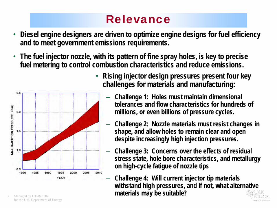
Relevance• Diesel engine designers are driven to optimize engine designs for fuel efficiency
and to meet government emissions requirements.
• The fuel injector nozzle, with its pattern of fine spray holes, is key to precise fuel metering to control combustion characteristics and reduce emissions.
• Rising injector design pressures present four key challenges for materials and manufacturing:– Challenge 1: Holes must maintain dimensional
tolerances and flow characteristics for hundreds of millions, or even billions of pressure cycles.
– Challenge 2: Nozzle materials must resist changes in shape, and allow holes to remain clear and open despite increasingly high injection pressures.
– Challenge 3: Concerns over the effects of residual stress state, hole bore characteristics, and metallurgy on high-cycle fatigue of nozzle tips
– Challenge 4: Will current injector tip materials withstand high pressures, and if not, what alternative materials may be suitable?
4 Managed by UT-Battellefor the U.S. Department of Energy
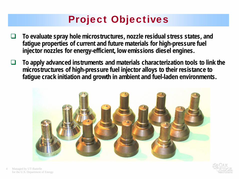
Project Objectives To evaluate spray hole microstructures, nozzle residual stress states, and
fatigue properties of current and future materials for high-pressure fuel injector nozzles for energy-efficient, low emissions diesel engines.
To apply advanced instruments and materials characterization tools to link the microstructures of high-pressure fuel injector alloys to their resistance to fatigue crack initiation and growth in ambient and fuel-laden environments.
5 Managed by UT-Battellefor the U.S. Department of Energy
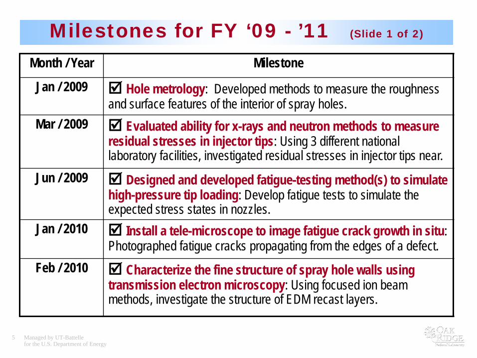
Milestones for FY ‘09 - ’11 (Slide 1 of 2)
Month / Year Milestone
Jan / 2009 Hole metrology: Developed methods to measure the roughness and surface features of the interior of spray holes.
Mar / 2009 Evaluated ability for x-rays and neutron methods to measure residual stresses in injector tips: Using 3 different national laboratory facilities, investigated residual stresses in injector tips near.
Jun / 2009 Designed and developed fatigue-testing method(s) to simulate high-pressure tip loading: Develop fatigue tests to simulate the expected stress states in nozzles.
Jan / 2010 Install a tele-microscope to image fatigue crack growth in situ: Photographed fatigue cracks propagating from the edges of a defect.
Feb / 2010 Characterize the fine structure of spray hole walls using transmission electron microscopy: Using focused ion beam methods, investigate the structure of EDM recast layers.
6 Managed by UT-Battellefor the U.S. Department of Energy
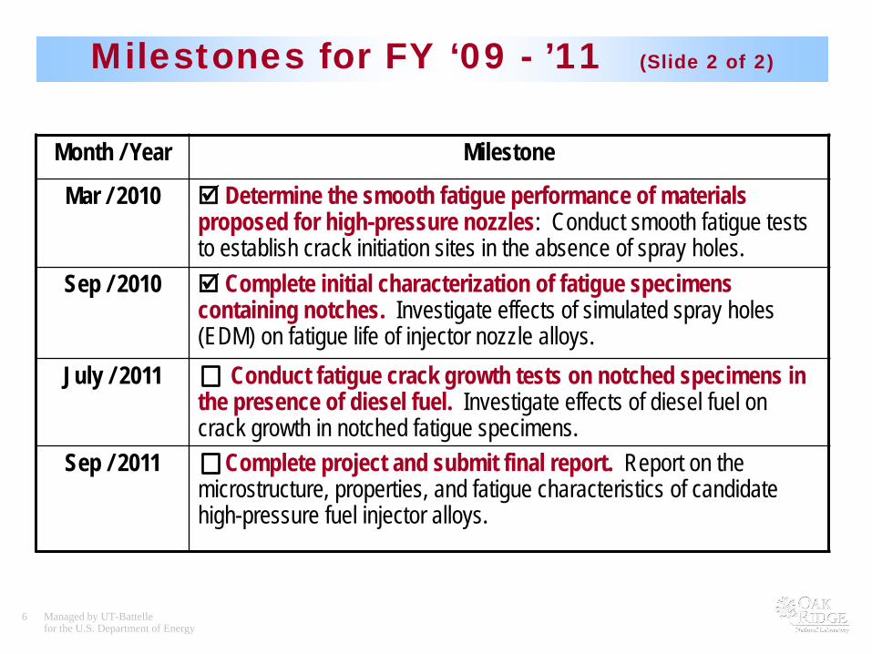
Milestones for FY ‘09 - ’11 (Slide 2 of 2)
Month / Year Milestone
Mar / 2010 Determine the smooth fatigue performance of materials proposed for high-pressure nozzles: Conduct smooth fatigue tests to establish crack initiation sites in the absence of spray holes.
Sep / 2010 Complete initial characterization of fatigue specimens containing notches. Investigate effects of simulated spray holes (EDM) on fatigue life of injector nozzle alloys.
July / 2011 Conduct fatigue crack growth tests on notched specimens in the presence of diesel fuel. Investigate effects of diesel fuel on crack growth in notched fatigue specimens.
Sep / 2011 Complete project and submit final report. Report on the microstructure, properties, and fatigue characteristics of candidate high-pressure fuel injector alloys.
7 Managed by UT-Battellefor the U.S. Department of Energy
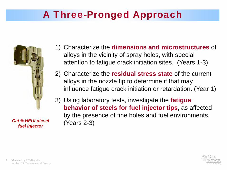
A Three-Pronged Approach
Cat ® HEUI diesel fuel injector
1) Characterize the dimensions and microstructures of alloys in the vicinity of spray holes, with special attention to fatigue crack initiation sites. (Years 1-3)
2) Characterize the residual stress state of the current alloys in the nozzle tip to determine if that may influence fatigue crack initiation or retardation. (Year 1)
3) Using laboratory tests, investigate the fatigue behavior of steels for fuel injector tips, as affected by the presence of fine holes and fuel environments. (Years 2-3)

8 Managed by UT-Battellefor the U.S. Department of Energy
Technical Accomplishments and Progress
1) Characterization of hole microstructures and hole walls
2) Characterization of hole morphology and interior roughness
3) Measurements of residual stress by x-ray and neutron scattering
4) Studies of micro- and nano-mechanical properties of hole walls
5) Studies of fatigue crack initiation and growth in nozzle alloys with and without simulated spray holes
Hole wall microstructure
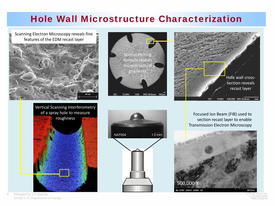
9 Managed by UT-Battellefor the U.S. Department of Energy
Hole Wall Microstructure Characterization
Vertical Scanning Interferometry of a spray hole to measure
roughness
Scanning Electron Microscopy reveals fine features of the EDM recast layer
Special etching formula reveals microstructural
gradientsHole wall cross-section reveals
recast layer
Focused Ion Beam (FIB) used to section recast layer to enable
Transmission Electron Microscopy
500,000 X
10 Managed by UT-Battellefor the U.S. Department of Energy
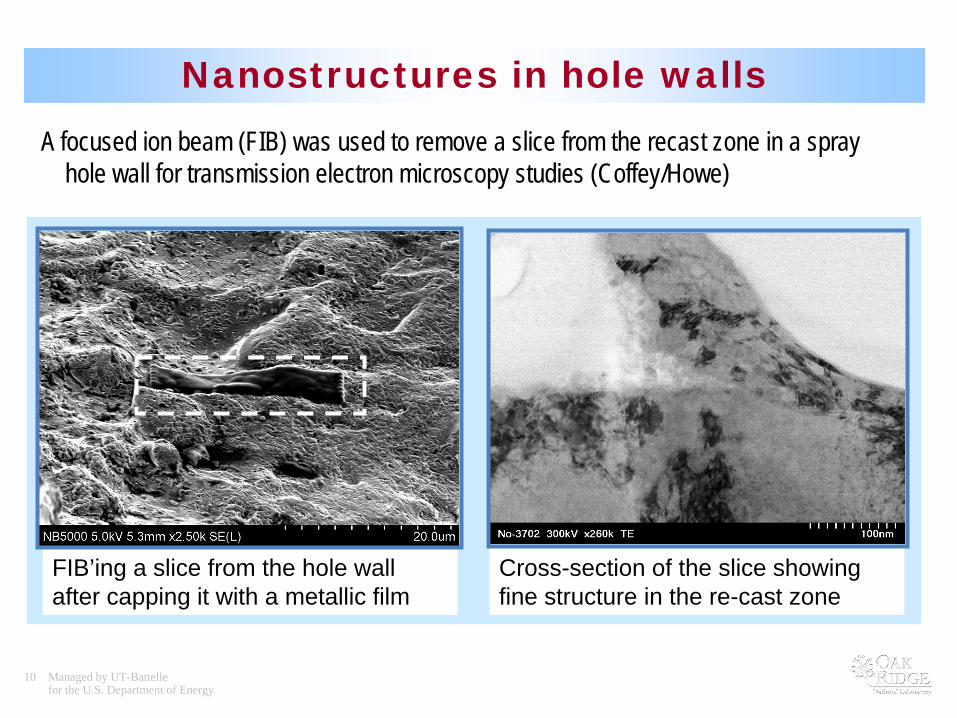
Nanostructures in hole wallsA focused ion beam (FIB) was used to remove a slice from the recast zone in a spray
hole wall for transmission electron microscopy studies (Coffey/Howe)
FIB’ing a slice from the hole wall after capping it with a metallic film
Cross-section of the slice showing fine structure in the re-cast zone
11 Managed by UT-Battellefor the U.S. Department of Energy
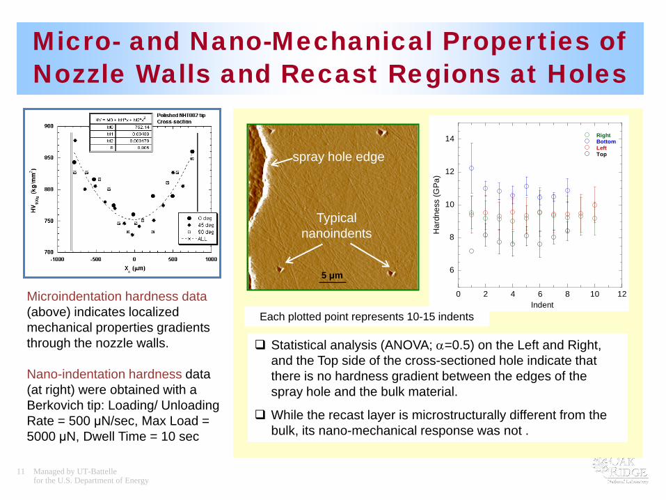
Micro- and Nano-Mechanical Properties of Nozzle Walls and Recast Regions at Holes
Microindentation hardness data (above) indicates localized mechanical properties gradients through the nozzle walls.
Nano-indentation hardness data (at right) were obtained with a Berkovich tip: Loading/ Unloading Rate = 500 μN/sec, Max Load = 5000 μN, Dwell Time = 10 sec
Statistical analysis (ANOVA; α=0.5) on the Left and Right, and the Top side of the cross-sectioned hole indicate that there is no hardness gradient between the edges of the spray hole and the bulk material.
While the recast layer is microstructurally different from the bulk, its nano-mechanical response was not .
5 μm 6
8
10
12
14
0 2 4 6 8 10 12
RightBottomLeftTop
Har
dnes
s (G
Pa)
Indent
spray hole edge
Typical nanoindents
Each plotted point represents 10-15 indents

12 Managed by UT-Battellefor the U.S. Department of Energy
Residual Stress Studies of Nozzles
Technique Facility Comments/findingsLaboratory XRD (ORNL / HTML) PTS
goniometerCompressive axial surface stresses resulting from carburizing treatment
Synchrotron XRD(low energy x-ray)
(BNL) NSLS – X14A Compressive stresses at surfaceBeam size limited to 1x2 mm (see figure below)
Neutron diffraction (ORNL / HTML) HFIR-NRSF2
Measured d-spacing through barrel wall. Gauge volume limited the ability to determine stress free d-zero needed to calculate strains.
Three DOE X-ray and neutron diffraction stress mapping facilities were used to study the feasibility of achieving the spatial dimensions needed to characterize specific locations on fuel injector nozzles.
Slope indicates slightly compressive stress

13 Managed by UT-Battellefor the U.S. Department of Energy
Fatigue Properties and microstructure of current and candidate materials
Rotation Bending Fatigue (RBF) tests were performed at Caterpillar on current and candidate materials. Failure analysis and microstructure studies were carried out and related to their fatigue performance.
Fatigue failure initiated at sub-surface inclusion
SEM image of an UHCF fracture surface of a surface-treated candidate material.
Normalized RBF test results of current and candidate fuel injector materials.
(LCF = low cycle fatigue, HCF = high-cycle fatigue, UHCF = ultra-high cycle fatigue)
14 Managed by UT-Battellefor the U.S. Department of Energy
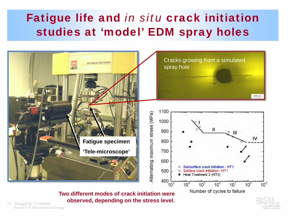
Fatigue life and in situ crack initiation studies at ‘model’ EDM spray holes
Fatigue specimen
‘Tele-microscope’
Cracks growing from a simulated spray hole
Two different modes of crack initiation were observed, depending on the stress level.

15 Managed by UT-Battellefor the U.S. Department of Energy
Summary of Annual ProgressThis Cooperative Research and Development Agreement (CRADA) is aimed at
characterizing materials that can withstand the demanding stress conditions of high-pressure diesel engine fuel injectors. Highlights of annual progress:
• (FY 08) Initial characterization of fuel injector spray holes features.
• (FY 09) X-ray and neutron-based methods investigated residual stresses in fuel injector nozzles. Results suggest that residual stresses in the nozzles are not a significant issue, and further work was suspended.
• (FY 09-10) A fatigue test protocol was developed and used to study fatigue crack initiation and propagation in nozzle materials, with and without simulated spray holes. A dual-mode of crack initiation was discovered in the alloy steel.
• (FY 10) Microstructures at the walls of spray holes were first studied using transmission electron microscopy and focused ion beam specimen preparation.
• (FY11) Current FY progress: nano-indentation studies, notched fatigue studies, extension of fatigue studies to the effects of diesel fuel environments.
16 Managed by UT-Battellefor the U.S. Department of Energy
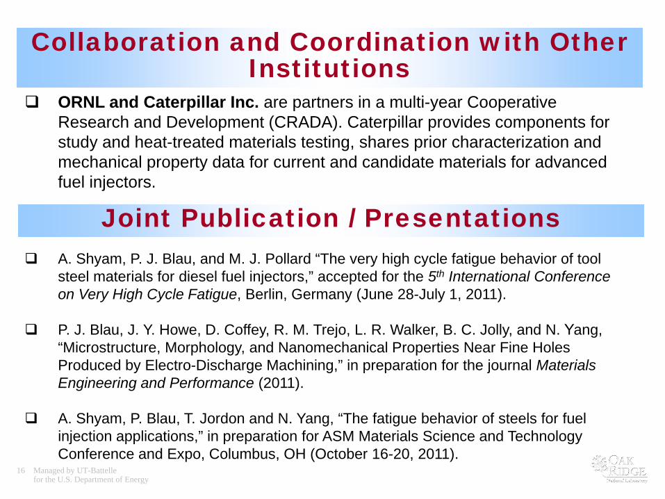
Collaboration and Coordination with Other Institutions
ORNL and Caterpillar Inc. are partners in a multi-year Cooperative Research and Development (CRADA). Caterpillar provides components for study and heat-treated materials testing, shares prior characterization and mechanical property data for current and candidate materials for advanced fuel injectors.
Joint Publication / Presentations A. Shyam, P. J. Blau, and M. J. Pollard “The very high cycle fatigue behavior of tool
steel materials for diesel fuel injectors,” accepted for the 5th International Conference on Very High Cycle Fatigue, Berlin, Germany (June 28-July 1, 2011).
P. J. Blau, J. Y. Howe, D. Coffey, R. M. Trejo, L. R. Walker, B. C. Jolly, and N. Yang, “Microstructure, Morphology, and Nanomechanical Properties Near Fine Holes Produced by Electro-Discharge Machining,” in preparation for the journal Materials Engineering and Performance (2011).
A. Shyam, P. Blau, T. Jordon and N. Yang, “The fatigue behavior of steels for fuel injection applications,” in preparation for ASM Materials Science and Technology Conference and Expo, Columbus, OH (October 16-20, 2011).

17 Managed by UT-Battellefor the U.S. Department of Energy
Acknowledgments• ORNL
– Peter Blau (co-principal investigator, metallurgical characterization)– Cam Hubbard (residual stress measurement and analysis)– Amit Shyam (fatigue and fracture testing and modeling)– Randy Parten (coordinate measurement and precision grinding)– Rosa Trejo (nanoindentation measurements)– Dorothy Coffey (FIB specimen preparation)– Jane Howe (TEM studies)
• CATERPILLAR:– Mike Pollard (prior principal investigator, fatigue, heat treatment effects)– Nan Yang (current principal investigator, fatigue studies)
The participants wish to gratefully acknowledge the guidance and support provided by Jerry Gibbs, DOE/EERE/OVT, and Ray Johnson, ORNL.
18 Managed by UT-Battellefor the U.S. Department of Energy
Proposed Future Work
Remainder of FY 2011:
• Effects of Heat Treatment on Fatigue: Continue fatigue testing of specimens containing EDM notches to study crack nucleation in current high-pressure fuel injector nozzle materials under heat-treated conditions.
• Environmental Effects on Fatigue: Investigate effects of diesel fuel surroundings on the initiation and propagation of fatigues near simulated spray holes.
• Final Report: Complete the project final report by CRADA partners ORNL and Caterpillar.
Proposed for FY 2012 – 2013 (new effort)
• Next-Generation Injector Materials: Application of the tools and experimental methods developed during the current project to study fatigue initiation and growth in next-generation alloys able to withstand maximum fuel injection pressures well in excess of 3000 bars in hot environments.
19 Managed by UT-Battellefor the U.S. Department of Energy
SUMMARY
• This project represents a cooperative research and development agreement (CRADA) between ORNL and Caterpillar, aimed at an issue critical to raising energy efficiency of advanced diesel engines.
• The effort addresses the challenge of durable material selection for use in diesel engine high-pressure fuel injection systems.
• A critical aspect is nozzle alloy fatigue performance under multiple pressure pulses, and the role of microstructural features in the initiation and propagation of fatigue damage in highly-stressed components.
• Residual stress does not seem to present a serious concern for the initiation of fatigue damage in nozzle tips (sacks) in current alloys.
• A better understanding of the applied stress versus fatigue life was obtained for the current nozzle material, and future plans include extending this understanding to candidate alloys with improved performance.