scan fuel system diagnosis -...
TRANSCRIPT
CHANGED BY
EFFECTIVE DATE
AFFECTED VIN
DIAGNOSISKYRON SM - 2005.09
157ECU
TC
US
CA
NE
CU
M/
TT
CC
UC
LU
TC
HB
RA
KE
A/B
AG
A/C
ON
FF
HR
K-S
TIC
SR
/SE
NS
OR
S/R
OO
F
FUEL SYSTEM DIAGNOSIS
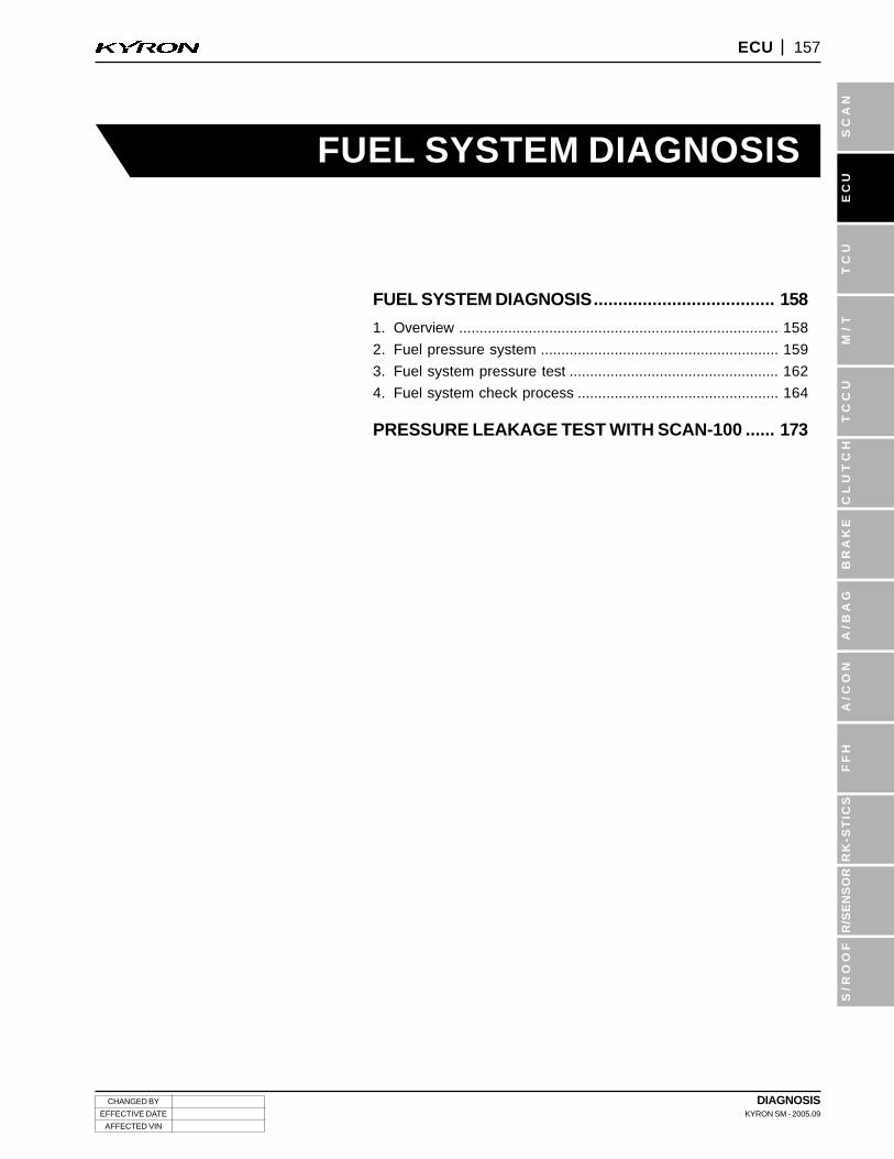
FUEL SYSTEM DIAGNOSIS..................................... 158
1. Overview .............................................................................. 158
2. Fuel pressure system .......................................................... 159
3. Fuel system pressure test ................................................... 162
4. Fuel system check process ................................................. 164
PRESSURE LEAKAGE TEST WITH SCAN-100 ...... 173
DIAGNOSISKYRON SM - 2005.09
CHANGED BY
EFFECTIVE DATE
AFFECTED VIN
158 ECU
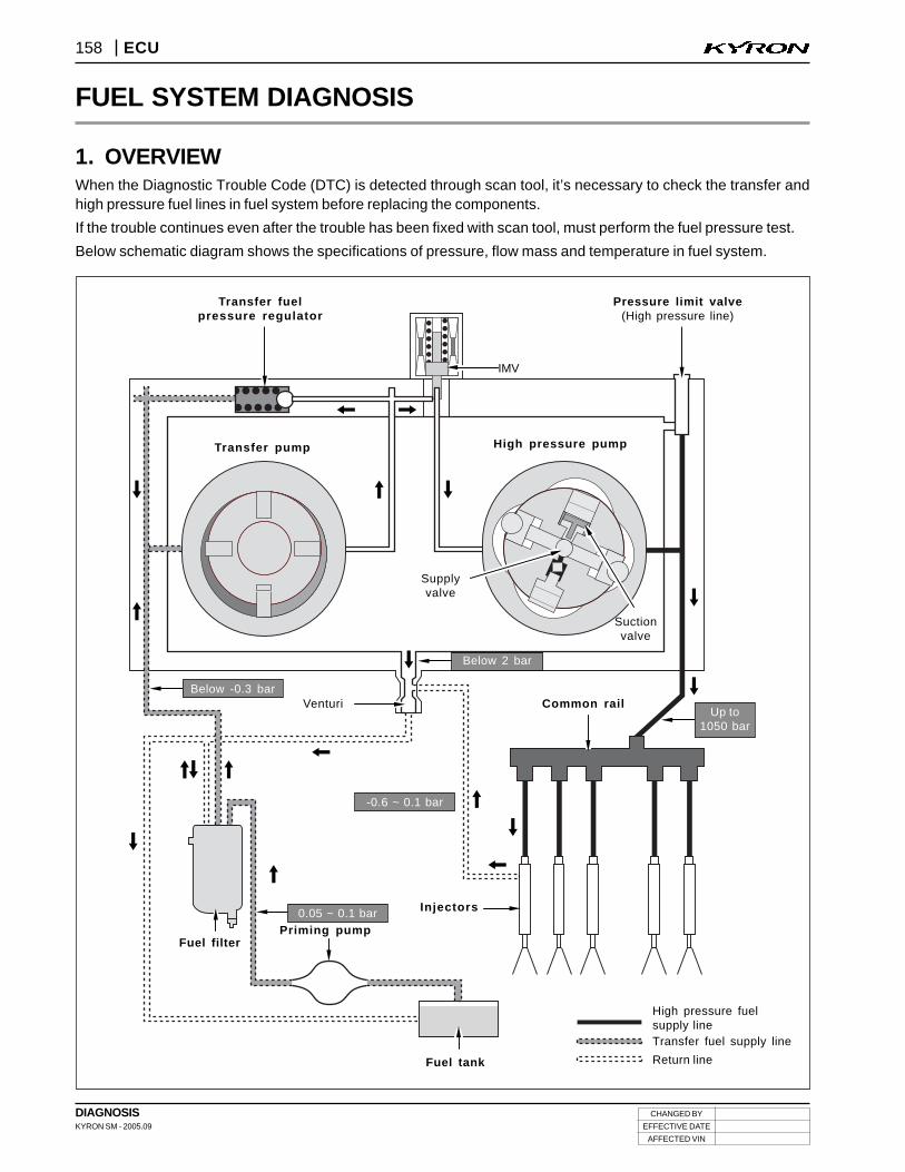
1. OVERVIEWWhen the Diagnostic Trouble Code (DTC) is detected through scan tool, it’s necessary to check the transfer andhigh pressure fuel lines in fuel system before replacing the components.
If the trouble continues even after the trouble has been fixed with scan tool, must perform the fuel pressure test.
Below schematic diagram shows the specifications of pressure, flow mass and temperature in fuel system.
Transfer fuelpressure regulator
Pressure limit valve(High pressure line)
Transfer pump
Supplyvalve
Suctionvalve
High pressure pump
Up to1050 bar
Common rail
Injectors
Fuel tank
Priming pumpFuel filter
Venturi
Below 2 bar
Below -0.3 bar
-0.6 ~ 0.1 bar
High pressure fuelsupply lineTransfer fuel supply line
Return line
IMV
-0.6 ~ 0.1 bar
0.05 ~ 0.1 bar
FUEL SYSTEM DIAGNOSIS
CHANGED BY
EFFECTIVE DATE
AFFECTED VIN
DIAGNOSISKYRON SM - 2005.09
159ECU
TC
US
CA
NE
CU
M/
TT
CC
UC
LU
TC
HB
RA
KE
A/B
AG
A/C
ON
FF
HR
K-S
TIC
SR
/SE
NS
OR
S/R
OO
F
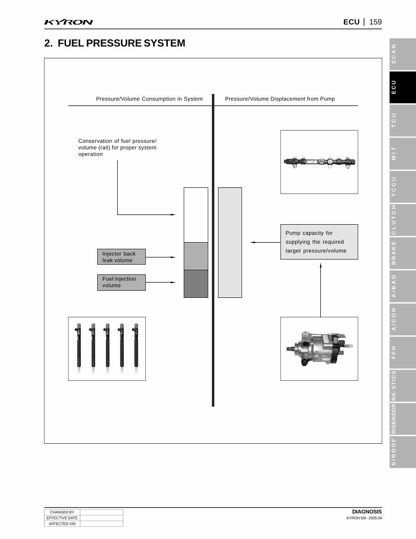
2. FUEL PRESSURE SYSTEM
Pressure/Volume Consumption in System Pressure/Volume Displacement from Pump
Injector backleak volume
Fuel injectionvolume
Pump capacity for
supplying the required
target pressure/volume
Conservation of fuel pressure/volume (rail) for proper systemoperation
DIAGNOSISKYRON SM - 2005.09
CHANGED BY
EFFECTIVE DATE
AFFECTED VIN
160 ECU
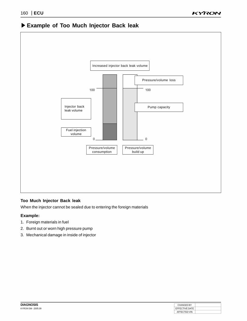
Example of Too Much Injector Back leak
Too Much Injector Back leak
When the injector cannot be sealed due to entering the foreign materials
Example:
1. Foreign materials in fuel
2. Burnt out or worn high pressure pump
3. Mechanical damage in inside of injector
Increased injector back leak volume
Pressure/volume loss
Pump capacity
Pressure/volumebuild up
Pressure/volumeconsumption
Fuel injectionvolume
Injector backleak volume
CHANGED BY
EFFECTIVE DATE
AFFECTED VIN
DIAGNOSISKYRON SM - 2005.09
161ECU
TC
US
CA
NE
CU
M/
TT
CC
UC
LU
TC
HB
RA
KE
A/B
AG
A/C
ON
FF
HR
K-S
TIC
SR
/SE
NS
OR
S/R
OO
F
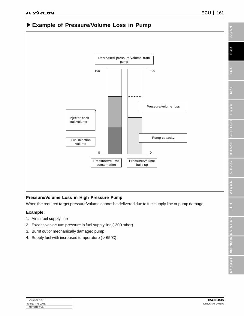
Example of Pressure/Volume Loss in Pump
Pressure/Volume Loss in High Pressure Pump
When the required target pressure/volume cannot be delivered due to fuel supply line or pump damage
Example:
1. Air in fuel supply line
2. Excessive vacuum pressure in fuel supply line (-300 mbar)
3. Burnt out or mechanically damaged pump
4. Supply fuel with increased temperature ( > 65°C)
Decreased pressure/volume frompump
Pressure/volume loss
Pump capacity
Pressure/volumebuild up
Pressure/volumeconsumption
Fuel injectionvolume
Injector backleak volume
DIAGNOSISKYRON SM - 2005.09
CHANGED BY
EFFECTIVE DATE
AFFECTED VIN
162 ECU
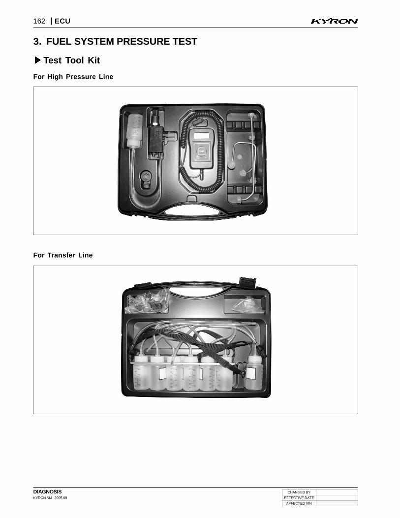
3. FUEL SYSTEM PRESSURE TEST
Test Tool Kit
For High Pressure Line
For Transfer Line
CHANGED BY
EFFECTIVE DATE
AFFECTED VIN
DIAGNOSISKYRON SM - 2005.09
163ECU
TC
US
CA
NE
CU
M/
TT
CC
UC
LU
TC
HB
RA
KE
A/B
AG
A/C
ON
FF
HR
K-S
TIC
SR
/SE
NS
OR
S/R
OO
F
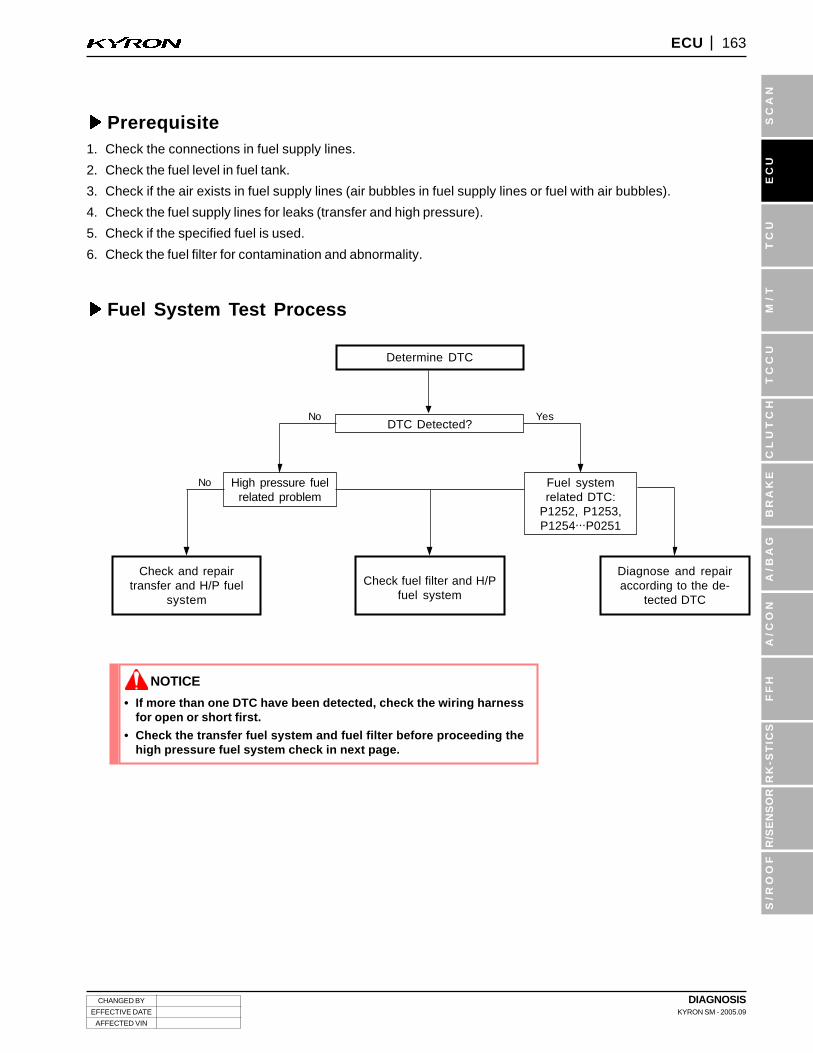
Prerequisite1. Check the connections in fuel supply lines.
2. Check the fuel level in fuel tank.
3. Check if the air exists in fuel supply lines (air bubbles in fuel supply lines or fuel with air bubbles).
4. Check the fuel supply lines for leaks (transfer and high pressure).
5. Check if the specified fuel is used.
6. Check the fuel filter for contamination and abnormality.
Fuel System Test Process
Determine DTC
DTC Detected?
Fuel systemrelated DTC:
P1252, P1253,P1254...P0251
High pressure fuelrelated problem
No
No
Yes
noCheck and repair
transfer and H/P fuelsystem
Check fuel filter and H/Pfuel system
Diagnose and repairaccording to the de-
tected DTC
• If more than one DTC have been detected, check the wiring harnessfor open or short first.
• Check the transfer fuel system and fuel filter before proceeding thehigh pressure fuel system check in next page.
NOTICE
DIAGNOSISKYRON SM - 2005.09
CHANGED BY
EFFECTIVE DATE
AFFECTED VIN
164 ECU
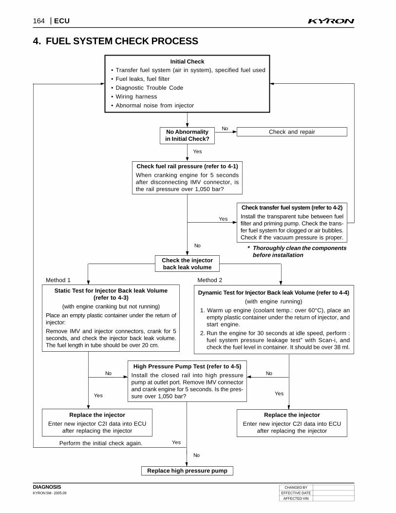
4. FUEL SYSTEM CHECK PROCESS
Initial Check• Transfer fuel system (air in system), specified fuel used
• Fuel leaks, fuel filter
• Diagnostic Trouble Code
• Wiring harness
• Abnormal noise from injector
No Abnormalityin Initial Check?
NoCheck and repair
No
Check transfer fuel system (refer to 4-2)
Install the transparent tube between fuelfilter and priming pump. Check the trans-fer fuel system for clogged or air bubbles.Check if the vacuum pressure is proper.
Check the injectorback leak volume
Replace high pressure pump
Yes
Yes
No
Yes
No
Yes
Yes
Replace the injector
Enter new injector C2I data into ECUafter replacing the injector
Replace the injector
Enter new injector C2I data into ECUafter replacing the injector
Perform the initial check again.
Method 1 Method 2
Dynamic Test for Injector Back leak Volume (refer to 4-4)
(with engine running)
1. Warm up engine (coolant temp.: over 60°C), place anempty plastic container under the return of injector, andstart engine.
2. Run the engine for 30 seconds at idle speed, perform :fuel system pressure leakage test” with Scan-i, andcheck the fuel level in container. It should be over 38 ml.
Check fuel rail pressure (refer to 4-1)
When cranking engine for 5 secondsafter disconnecting IMV connector, isthe rail pressure over 1,050 bar?
* Thoroughly clean the componentsbefore installation
High Pressure Pump Test (refer to 4-5)
Install the closed rail into high pressurepump at outlet port. Remove IMV connectorand crank engine for 5 seconds. Is the pres-sure over 1,050 bar?
Static Test for Injector Back leak Volume(refer to 4-3)
(with engine cranking but not running)
Place an empty plastic container under the return ofinjector:
Remove IMV and injector connectors, crank for 5seconds, and check the injector back leak volume.The fuel length in tube should be over 20 cm.
No
CHANGED BY
EFFECTIVE DATE
AFFECTED VIN
DIAGNOSISKYRON SM - 2005.09
165ECU
TC
US
CA
NE
CU
M/
TT
CC
UC
LU
TC
HB
RA
KE
A/B
AG
A/C
ON
FF
HR
K-S
TIC
SR
/SE
NS
OR
S/R
OO
F
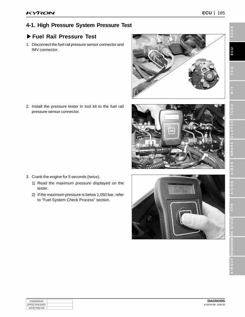
4-1. High Pressure System Pressure Test
Fuel Rail Pressure Test1. Disconnect the fuel rail pressure sensor connector and
IMV connector.
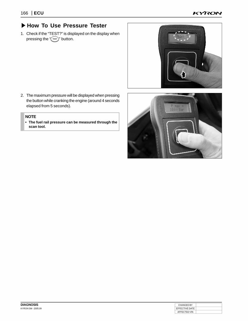
2. Install the pressure tester in tool kit to the fuel railpressure sensor connector.
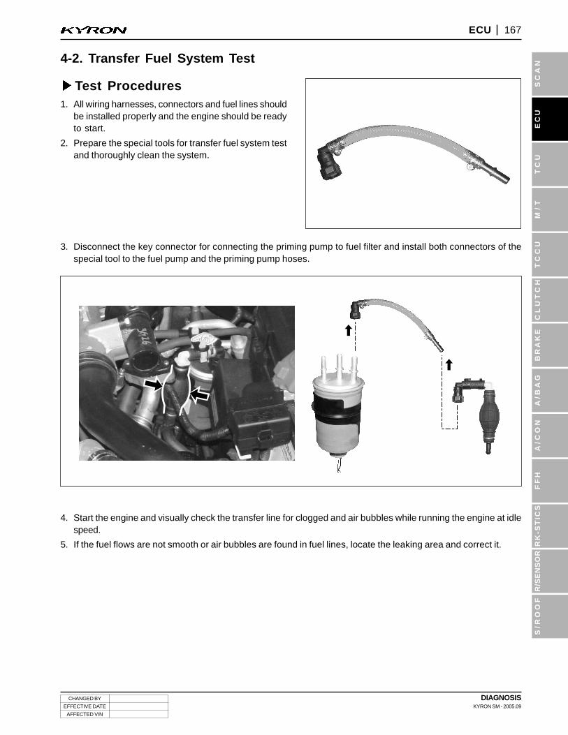
3. Crank the engine for 5 seconds (twice).
1) Read the maximum pressure displayed on thetester.
2) If the maximum pressure is below 1,050 bar, referto “Fuel System Check Process” section.
DIAGNOSISKYRON SM - 2005.09
CHANGED BY
EFFECTIVE DATE
AFFECTED VIN
166 ECU
How To Use Pressure Tester1. Check if the “TEST?” is displayed on the display when
pressing the “ ” button.
2. The maximum pressure will be displayed when pressingthe button while cranking the engine (around 4 secondselapsed from 5 seconds).
• The fuel rail pressure can be measured through thescan tool.
NOTE
CHANGED BY
EFFECTIVE DATE
AFFECTED VIN
DIAGNOSISKYRON SM - 2005.09
167ECU
TC
US
CA
NE
CU
M/
TT
CC
UC
LU
TC
HB
RA
KE
A/B
AG
A/C
ON
FF
HR
K-S
TIC
SR
/SE
NS
OR
S/R
OO
F
4-2. Transfer Fuel System Test
Test Procedures1. All wiring harnesses, connectors and fuel lines should
be installed properly and the engine should be readyto start.
2. Prepare the special tools for transfer fuel system testand thoroughly clean the system.
3. Disconnect the key connector for connecting the priming pump to fuel filter and install both connectors of thespecial tool to the fuel pump and the priming pump hoses.
4. Start the engine and visually check the transfer line for clogged and air bubbles while running the engine at idlespeed.
5. If the fuel flows are not smooth or air bubbles are found in fuel lines, locate the leaking area and correct it.
DIAGNOSISKYRON SM - 2005.09
CHANGED BY
EFFECTIVE DATE
AFFECTED VIN
168 ECU
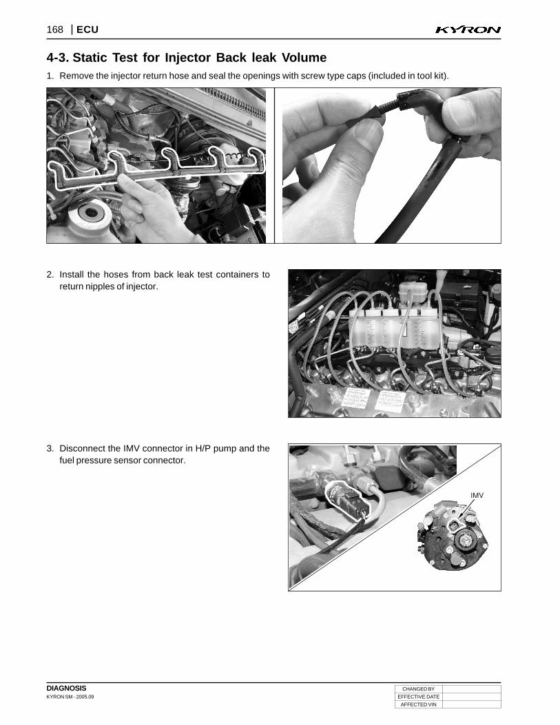
4-3. Static Test for Injector Back leak Volume1. Remove the injector return hose and seal the openings with screw type caps (included in tool kit).
2. Install the hoses from back leak test containers toreturn nipples of injector.
3. Disconnect the IMV connector in H/P pump and thefuel pressure sensor connector.
CHANGED BY
EFFECTIVE DATE
AFFECTED VIN
DIAGNOSISKYRON SM - 2005.09
169ECU
TC
US
CA
NE
CU
M/
TT
CC
UC
LU
TC
HB
RA
KE
A/B
AG
A/C
ON
FF
HR
K-S
TIC
SR
/SE
NS
OR
S/R
OO
F
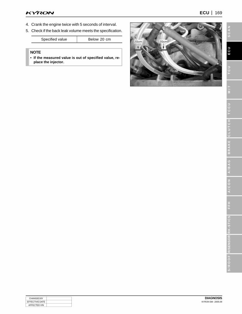
Specified value Below 20 cm
4. Crank the engine twice with 5 seconds of interval.
5. Check if the back leak volume meets the specification.
• If the measured value is out of specified value, re-place the injector.
NOTE
DIAGNOSISKYRON SM - 2005.09
CHANGED BY
EFFECTIVE DATE
AFFECTED VIN
170 ECU
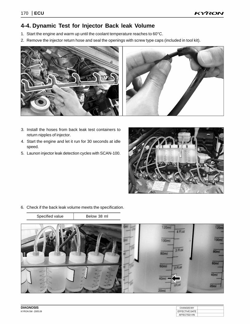
4-4. Dynamic Test for Injector Back leak Volume1. Start the engine and warm up until the coolant temperature reaches to 60°C.
2. Remove the injector return hose and seal the openings with screw type caps (included in tool kit).
3. Install the hoses from back leak test containers toreturn nipples of injector.
4. Start the engine and let it run for 30 seconds at idlespeed.
5. Launon injector leak detection cycles with SCAN-100.
6. Check if the back leak volume meets the specification.
Specified value Below 38 ml
CHANGED BY
EFFECTIVE DATE
AFFECTED VIN
DIAGNOSISKYRON SM - 2005.09
171ECU
TC
US
CA
NE
CU
M/
TT
CC
UC
LU
TC
HB
RA
KE
A/B
AG
A/C
ON
FF
HR
K-S
TIC
SR
/SE
NS
OR
S/R
OO
F
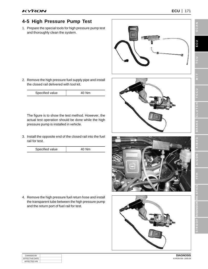
4-5 High Pressure Pump Test1. Prepare the special tools for high pressure pump test
and thoroughly clean the system.
Specified value 40 Nm
Specified value 40 Nm
The figure is to show the test method. However, theactual test operation should be done while the highpressure pump is installed in vehicle.
2. Remove the high pressure fuel supply pipe and installthe closed rail delivered with tool kit.
3. Install the opposite end of the closed rail into the fuelrail for test.
4. Remove the high pressure fuel return hose and installthe transparent tube between the high pressure pumpand the return port of fuel rail for test.
DIAGNOSISKYRON SM - 2005.09
CHANGED BY
EFFECTIVE DATE
AFFECTED VIN
172 ECU
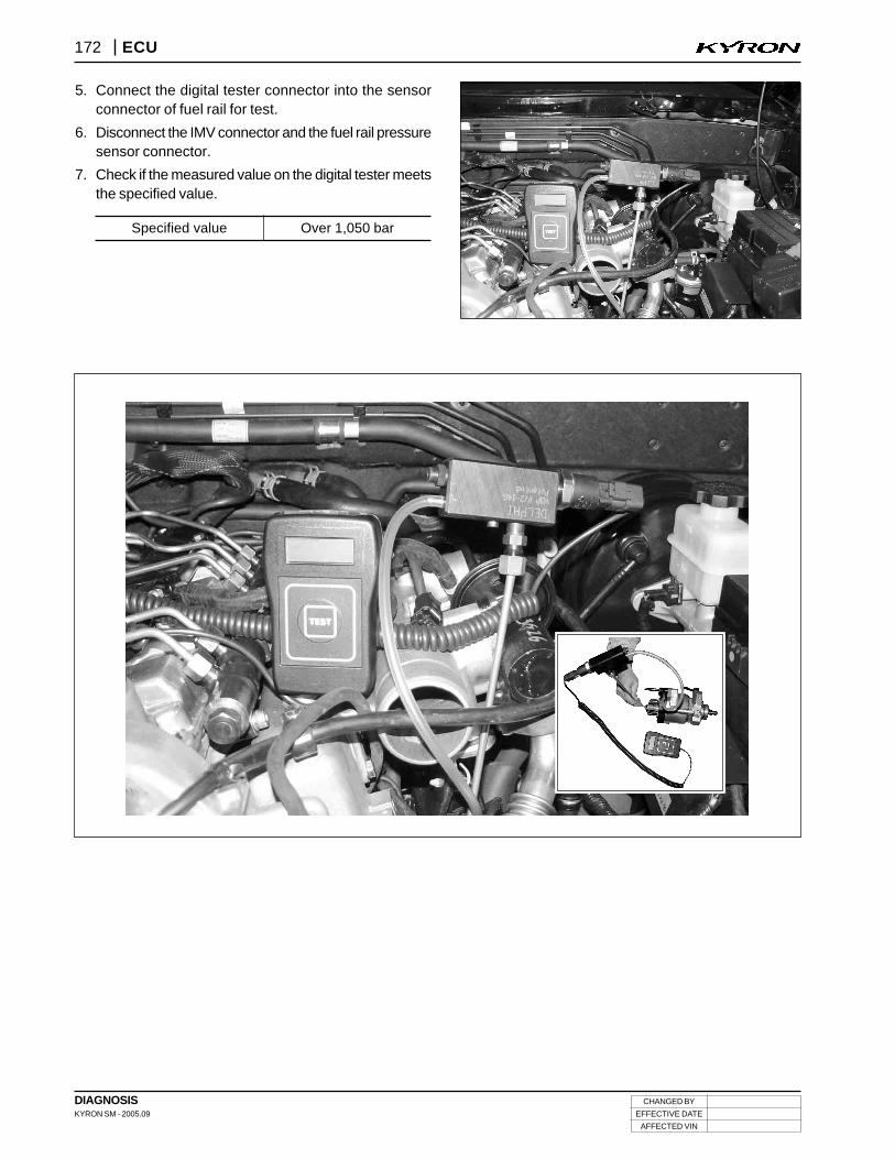
5. Connect the digital tester connector into the sensorconnector of fuel rail for test.
6. Disconnect the IMV connector and the fuel rail pressuresensor connector.
7. Check if the measured value on the digital tester meetsthe specified value.
Specified value Over 1,050 bar
CHANGED BY
EFFECTIVE DATE
AFFECTED VIN
DIAGNOSISKYRON SM - 2005.09
173ECU
TC
US
CA
NE
CU
M/
TT
CC
UC
LU
TC
HB
RA
KE
A/B
AG
A/C
ON
FF
HR
K-S
TIC
SR
/SE
NS
OR
S/R
OO
F
1. When performing the static test for injector back leak Volume, the fuel pressure leakage test with SCAN-100should be done simultaneously. And, the fuel pressure leakage test with SCAN-100 can be done separately.
2. Test Conditions:
1) No defective or faulty sensors and components in fuel system: checked by Scan-100
2) Coolant temperature: over 60°C
3. The diagnosis procedures with SCAN-100 are as below:
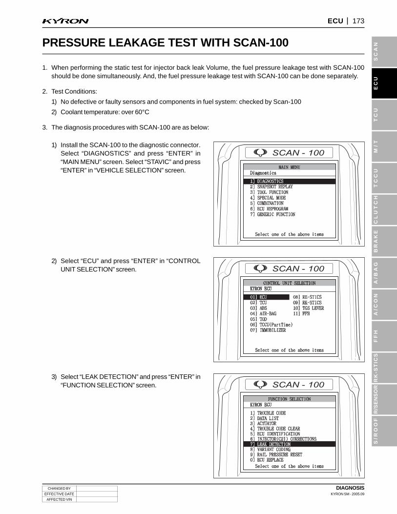
1) Install the SCAN-100 to the diagnostic connector.Select “DIAGNOSTICS” and press “ENTER” in“MAIN MENU” screen. Select “STAVIC” and press“ENTER” in “VEHICLE SELECTION” screen.
2) Select “ECU” and press “ENTER” in “CONTROLUNIT SELECTION” screen.
3) Select “LEAK DETECTION” and press “ENTER” in“FUNCTION SELECTION” screen.
PRESSURE LEAKAGE TEST WITH SCAN-100
DIAGNOSISKYRON SM - 2005.09
CHANGED BY
EFFECTIVE DATE
AFFECTED VIN
174 ECU
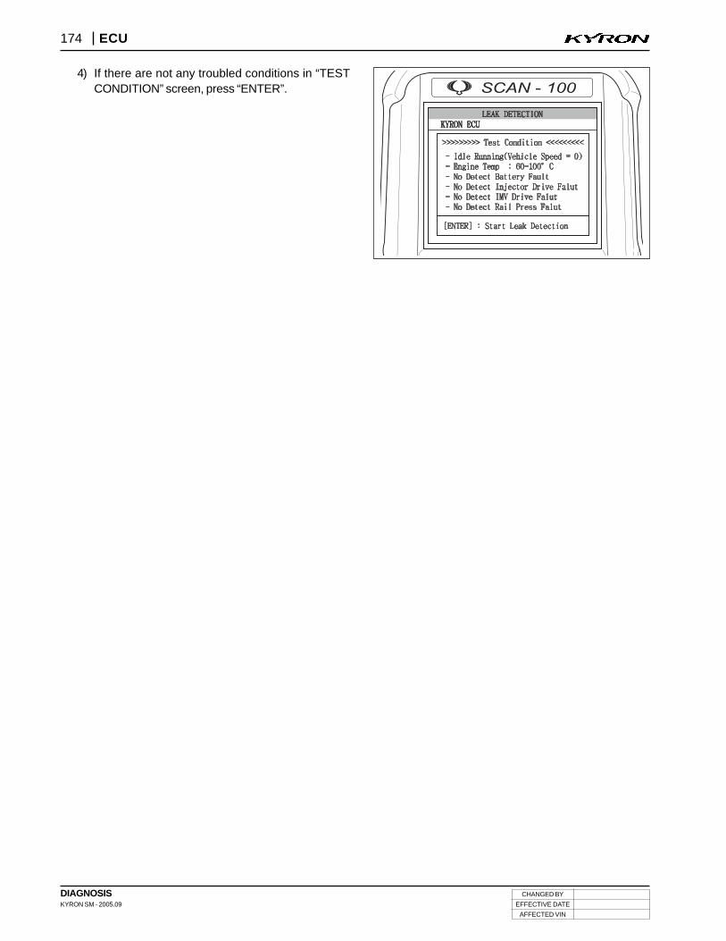
4) If there are not any troubled conditions in “TESTCONDITION” screen, press “ENTER”.