material reliability program: primary system piping butt ...report summary this materials...
TRANSCRIPT

Material Reliability Program: Primary System Piping Butt Weld Inspection and Evaluation Guideline
(MRP-139, Revision 1)


EPRI Project Manager C. Harrington
ELECTRIC POWER RESEARCH INSTITUTE 3420 Hillview Avenue, Palo Alto, California 94304-1338 ▪ PO Box 10412, Palo Alto, California 94303-0813 ▪ USA
800.313.3774 ▪ 650.855.2121 ▪ [email protected] ▪ www.epri.com
Material Reliability Program: Primary System Piping Butt Weld Inspection and Evaluation Guideline (MRP-139, Revision 1) 1015009
Final Report, December 2008

DISCLAIMER OF WARRANTIES AND LIMITATION OF LIABILITIES
THIS DOCUMENT WAS PREPARED BY THE ORGANIZATION(S) NAMED BELOW AS AN ACCOUNT OF WORK SPONSORED OR COSPONSORED BY THE ELECTRIC POWER RESEARCH INSTITUTE, INC. (EPRI). NEITHER EPRI, ANY MEMBER OF EPRI, ANY COSPONSOR, THE ORGANIZATION(S) BELOW, NOR ANY PERSON ACTING ON BEHALF OF ANY OF THEM:
(A) MAKES ANY WARRANTY OR REPRESENTATION WHATSOEVER, EXPRESS OR IMPLIED, (I) WITH RESPECT TO THE USE OF ANY INFORMATION, APPARATUS, METHOD, PROCESS, OR SIMILAR ITEM DISCLOSED IN THIS DOCUMENT, INCLUDING MERCHANTABILITY AND FITNESS FOR A PARTICULAR PURPOSE, OR (II) THAT SUCH USE DOES NOT INFRINGE ON OR INTERFERE WITH PRIVATELY OWNED RIGHTS, INCLUDING ANY PARTY'S INTELLECTUAL PROPERTY, OR (III) THAT THIS DOCUMENT IS SUITABLE TO ANY PARTICULAR USER'S CIRCUMSTANCE; OR
(B) ASSUMES RESPONSIBILITY FOR ANY DAMAGES OR OTHER LIABILITY WHATSOEVER (INCLUDING ANY CONSEQUENTIAL DAMAGES, EVEN IF EPRI OR ANY EPRI REPRESENTATIVE HAS BEEN ADVISED OF THE POSSIBILITY OF SUCH DAMAGES) RESULTING FROM YOUR SELECTION OR USE OF THIS DOCUMENT OR ANY INFORMATION, APPARATUS, METHOD, PROCESS, OR SIMILAR ITEM DISCLOSED IN THIS DOCUMENT.
ORGANIZATION(S) THAT PREPARED THIS DOCUMENT
Electric Power Research Institute
NOTE
For further information about EPRI, call the EPRI Customer Assistance Center at 800.313.3774 or e-mail [email protected].
Electric Power Research Institute, EPRI, and TOGETHER…SHAPING THE FUTURE OF ELECTRICITY are registered service marks of the Electric Power Research Institute, Inc.
Copyright © 2008 Electric Power Research Institute, Inc. All rights reserved.

iii
CITATIONS
This report was prepared by EPRI with the assistance of the Assessment Issue Task Group and MRP-139 Review Board members. In addition, leadership and assistance in resolving many detailed issues was provided by:
G. Kammerdeiner, First Energy, Chairman D. Covill, Progress Energy
This report describes research sponsored by the Electric Power Research Institute (EPRI).
The report is a corporate document that should be cited in the literature in the following manner:
Material Reliability Program: Primary System Piping Butt Weld Inspection and Evaluation Guideline (MRP-139, Revision 1). EPRI, Palo Alto, CA: 2008. 1015009.


v
REPORT SUMMARY
This Materials Reliability Program (MRP) project identified butt weld locations susceptible to primary water stress corrosion cracking (PWSCC) and developed approaches for inspection, re-inspection, mitigation, and flaw evaluation.
Background PWSCC of Alloy 600 nozzles and penetration locations in pressurized water reactor (PWR) plant primary system pressure boundaries has been a recurring problem since the mid 1980s. During the second half of 2000, cracks were discovered in Alloy 182 welds joining low-alloy steel reactor vessel hot leg nozzles to stainless steel pipes at Ringhals 4 (Sweden) and VC Summer (United States). At VC Summer, a through-wall leaking flaw was found in the Alloy 82/182 weld between the low-alloy steel reactor vessel outlet nozzle and the stainless steel primary coolant pipe. Although cracking was primarily axially oriented, at VC Summer a short and shallow circumferential crack also was discovered in the inside diameter (ID) region of the Alloy 182 weld clad beneath the low-alloy steel nozzle material. This circumferential crack arrested when it reached the low-alloy steel base material. Although not a significant flaw in terms of structural integrity, the VC Summer circumferential flaw heightened the concern regarding circumferential flaws and their impact on structural integrity.
In 2003, a small leak was discovered from an Alloy 132 (similar to Alloy 182) butt weld on a pressurizer relief nozzle at Tsuruga 2 (Japan). This leak was from an axial crack in the butt weld between the low-alloy steel nozzle and the stainless steel relief valve line.
In Spring 2005, Calvert Cliffs Nuclear Power Plant (United States) identified indications in a 2-inch-diameter hot leg drain nozzle dissimilar metal weld. There were two (2) axial indications contained entirely within the weld and butter closely associated with the ID, located approximately 180° apart. There also was one (1) circumferential indication proximate to the ID extending approximately 100° in circumference, with one end oriented near one of the axial indications. The circumferential indication has been determined to be construction-related. The axial indications are being attributed to PWSCC.
Axial indications (some of which were subsequently confirmed as cracks) without associated leaks have been discovered in butt welds at a number of plants, including Ringhals 3 and 4 (Sweden), V.C. Summer (United States), Tsuruga 2 (Japan), Three Mile Island Unit 1 (United States), Farley 2 (United States), and Davis Besse 1 (United States). Additionally, several plants in Japan have recently discovered part-through wall cracks with both axial and circumferential characteristics in a number of steam generator nozzle dissimilar metal (DM) welds. Although no through-wall circumferential cracks have been discovered, part through-wall indications and cracks have been identified at a few plants, including Farley 2 (United States) and as noted above in several plants in Japan as reflected in very recent reports. Most notable are five
vi
circumferential indications discovered in three pressurizer nozzles at Wolf Creek (United States) in October 2006. These indications ranged from 8º to 166º of arc length and up to an estimated 31% through wall. The relevancy of the Wolf Creek experience resulted in a thorough re-examination of the technical basis and inspection guidance of this guideline.
Objectives To provide generic inspection and evaluation (I&E) guidelines for PWR primary system piping butt welds.
Approach MRP formed a focus group to develop PWR butt weld I&E guidelines. The group, comprised of utility and industry experts, reviewed available information, including PWSCC experience and the MRP Alloy 82/182 Butt Weld Safety Assessment, to develop this generic I&E guideline. This information was used to identify butt weld locations susceptible to PWSCC and to develop approaches for inspection, re-inspection, mitigation, and flaw evaluation. This revision incorporates or addresses plant experience, plant inquiries, and Nuclear Regulatory Commission (NRC) comments.
Results The I&E guidelines provide information on butt welds in primary systems, a discussion of susceptibility considerations, a “baseline” approach for the first inspection each plant will perform to new MRP requirements, and an approach for re-inspections.
The guidelines also contain a flaw evaluation methodology that provides guidance on performing flaw evaluations and assessing effectiveness of stress improvement (SI) processes.
EPRI Perspective These guidelines are mandatory and serve to augment current regulatory requirements for inspecting Alloy 82/182 butt welds for PWR owners. The MRP Assessment Issue Task Group (ITG) plans to monitor results of all inspections closely so that new information obtained from these inspections can be factored into subsequent revisions of this document. Revision 1 has been prepared to reflect the first several years of implementation experience as well as to incorporate approved interim guidance, address comments received from the NRC, and clarify the original text in a number of places. This revision makes no new changes or additions to the implementation dates contained in Section 1.2; all such changes have been previously addressed in the following interim guidance letters: MRP 2006-018, “MRP-139 Interim Guidance” (schedule deviations) MRP 2007-038, “MRP-139 Interim Guidance on <4” Volumetric Exam Requirements” MRP 2007-039, “MRP-139 Interim Guidance on Bare Metal Visual Exam Requirements” MRP 2008-033, “MRP-139 Interim Guidance on Cast Austenitic Stainless steel Exam
Requirements”
Keywords DM weld Dissimilar metal weld Butt weld Alloy 600 Alloy 82/182 PWSCC (primary water stress corrosion cracking) NEI-03-08 Inspection and evaluation guideline

vii
RECORD OF REVISION
Revision Description of Change
0 Original Issue
1 This revision reflects the first several years of implementation experience as well as to incorporate approved interim guidance, address comments received from NRC, and clarify the original text in a number of places. This revision makes no new changes or additions to the implementation dates contained in Section 1.2; all such changes have been previously addressed in the following interim guidance letters:
• MRP 2006-018, “MRP-139 Interim Guidance” (schedule deviations);
• MRP 2007-038, “MRP-139 Interim Guidance on <4” Volumetric Exam Requirements”;
• MRP 2007-039, “MRP-139 Interim Guidance on Bare Metal Visual Exam Requirements”;
• MRP 2008-033, “MPR-139 Interim Guidance on Cast Austenitic Stainless Steel Exam Requirements”.
See Appendix C for a listing of change bases for this revision.


ix
CONTENTS
1 INTRODUCTION ..................................................................................................................1-1 1.1 Objectives and Scope ....................................................................................................1-2
1.2 Implementation Schedule ..............................................................................................1-3
1.3 Examination Methodology Bases ...................................................................................1-5
2 PWR PRIMARY SYSTEM PIPING DESIGN AND SUSCEPTIBILITY INFORMATION .........2-1 2.1 Butt Weld Locations .......................................................................................................2-1
2.2 Locations in Westinghouse Design Plants .....................................................................2-1
2.3 Locations in Combustion Engineering Design Plants .....................................................2-2
2.4 Locations in B&W Design Plants ...................................................................................2-2
2.5 Locations with Alloy 600 Safe Ends ...............................................................................2-2
2.6 Susceptibility Information ...............................................................................................2-3
2.6.1 Crack Initiation: Material Susceptibility, Tensile Stress, and Environment ..............2-3
2.6.1.1 Susceptible Material .......................................................................................2-3
2.6.1.2 Tensile Stress ................................................................................................2-4
2.6.1.3 Environment ...................................................................................................2-4
2.6.2 Crack Growth Rates ...............................................................................................2-5
2.6.3 Effect of Design and Fabrication Practices on Initiation and Growth.......................2-6
2.6.3.1 Welding Processes and Material ....................................................................2-6
2.6.3.2 Weld Repairs ..................................................................................................2-7
2.6.3.3 Machining Inside Surface After Welding .........................................................2-7
2.6.3.4 Welding and Grinding on Inside Surface.........................................................2-7
2.6.4 Welding Residual and Operating Stresses .............................................................2-8
2.6.4.1 Flaw Orientation: Axial vs. Circumferential .....................................................2-8
2.6.4.1.1 PWR Field Experience ............................................................................2-8
2.6.4.1.2 BWR Field Experience ............................................................................2-9
2.6.4.1.3 Finite Element Stress Analysis ................................................................2-9
x
3 SUMMARY OF PWSCC MITIGATION PROCESSES ...........................................................3-1 3.1 Mitigation by Modification of Materials ...........................................................................3-1
3.2 Mitigation by Stress Improvement ..................................................................................3-2
3.2.1 SI of Uncracked Weldments ...................................................................................3-2
3.2.2 SI of Cracked Weldments ......................................................................................3-2
3.3 Mitigation by Environment .............................................................................................3-3
3.3.1 Change in Electrochemical Potential (ECP) ...........................................................3-3
3.3.2 Zinc Addition ..........................................................................................................3-4
3.3.3 Temperature ..........................................................................................................3-4
4 CURRENT EXAMINATION REQUIREMENTS AND RESULTS ...........................................4-1 4.1 ASME Code Section XI Examination Requirements ......................................................4-1
4.1.1 ASME Weld Risk Informed Section XI Examination ...............................................4-1
4.2 Flaw Detection Capability ..............................................................................................4-2
4.2.1 Visual Examination ................................................................................................4-2
4.2.2 Surface Examination ..............................................................................................4-2
4.2.3 Volumetric Examination: Experience Prior to About 1990 ......................................4-2
4.2.4 Volumetric Examination: Improvements After 1990 ................................................4-3
4.2.5 Volumetric Examination: Summary Status .............................................................4-4
4.3 Examination Results Through Spring 2004 Refueling Outages......................................4-4
4.4 MRP-139, Rev. 1 Update - Examination Results Through 2007 Refueling Outages ......4-5
4.5 Conclusions Regarding Butt Weld Condition .................................................................4-5
5 EXAMINATION REQUIREMENTS .......................................................................................5-1 5.1 Volumetric Examination Methods ..................................................................................5-3
5.1.1 ASME Section XI, Appendix VIII Qualified Procedures (Figure 5-1, Item 1) ..........5-3
5.1.2 Specific Weld Dimensions (Figure 5-1, Item 2) ......................................................5-4
5.1.3 DM Weld PDI Qualification (Figure 5-1, Item 3) .....................................................5-5
5.1.4 Site-Specific Demonstration (Figure 5-1, Item 4) ....................................................5-5
5.1.5 Coverage Assessment (Figure 5-1, Items 5, 6, and 7) ...........................................5-6
5.1.6 Improved Coverage (Figure 5-1, Item 8) ................................................................5-6
5.1.7 Requirements If Inspections Will Not be Completed as Required ...........................5-7
5.1.8 NDE Methodology Conclusion ...............................................................................5-9
5.2 Visual Examination Requirements .................................................................................5-9
5.2.1 Visual Examination ................................................................................................5-9

xi
6 EXAMINATION SCHEDULES ..............................................................................................6-1 6.1 Category A ....................................................................................................................6-3
6.1.1 Definition ................................................................................................................6-3
6.1.2 Examination Requirement ......................................................................................6-4
6.1.3 Basis ......................................................................................................................6-4
6.2 Category B ....................................................................................................................6-4
6.2.1 Definition ................................................................................................................6-4
6.2.2 Examination Requirement ......................................................................................6-4
6.2.3 Basis ......................................................................................................................6-4
6.3 Category C ....................................................................................................................6-5
6.3.1 Definition ................................................................................................................6-5
6.3.2 Examination Requirement ......................................................................................6-6
6.3.3 Basis ......................................................................................................................6-6
6.4 Category D ....................................................................................................................6-7
6.4.1 Definition ................................................................................................................6-7
6.4.2 Examination Requirement ......................................................................................6-7
6.4.3 Basis ......................................................................................................................6-7
6.5 Category E ....................................................................................................................6-8
6.5.1 Definition ................................................................................................................6-8
6.5.2 Examination Requirement ......................................................................................6-8
6.5.3 Basis ......................................................................................................................6-8
6.6 Category F.....................................................................................................................6-8
6.6.1 Definition ................................................................................................................6-8
6.6.2 Examination Requirement ......................................................................................6-9
6.6.3 Basis ......................................................................................................................6-9
6.7 Category G .................................................................................................................. 6-10
6.7.1 Definition .............................................................................................................. 6-10
6.7.2 Examination Requirement .................................................................................... 6-10
6.7.3 Basis .................................................................................................................... 6-10
6.8 Category H .................................................................................................................. 6-11
6.8.1 Definition .............................................................................................................. 6-11
6.8.2 Examination Requirement .................................................................................... 6-11
6.8.3 Basis .................................................................................................................... 6-11
6.9 Category I .................................................................................................................... 6-12

xii
6.9.1 Definition .............................................................................................................. 6-12
6.9.2 Examination Requirement .................................................................................... 6-12
6.9.3 Basis .................................................................................................................... 6-12
6.10 Visual Examinations—Category J .............................................................................. 6-12
6.10.1 Definition ............................................................................................................ 6-12
6.10.2 Examination Requirement .................................................................................. 6-13
6.10.3 Basis .................................................................................................................. 6-13
6.11 Visual Examinations—Category K ............................................................................. 6-13
6.11.1 Definition ............................................................................................................ 6-13
6.11.2 Examination Requirement .................................................................................. 6-13
6.11.3 Basis .................................................................................................................. 6-13
7 EVALUATION METHODOLOGIES ......................................................................................7-1 7.1 Indication Disposition .....................................................................................................7-2
7.1.1 Allowable Flaw Size ...............................................................................................7-2
7.1.2 Crack Growth Calculation ......................................................................................7-2
7.1.3 Determination of Flaw Acceptance .........................................................................7-3
7.1.4 Stress Improvement Effectiveness .........................................................................7-3
7.1.5 Weld Overlay Design .............................................................................................7-4
8 SUMMARY ..........................................................................................................................8-1 8.1 Table 8-1 Required Actions Summary ...........................................................................8-1
9 REFERENCES ....................................................................................................................9-1
A DM WELD MEASUREMENT TEMPLATE........................................................................... A-1
B DM WELD MOCKUP CRITERIA 5/28/04 ............................................................................ B-1
C RECORD OF REVISION ..................................................................................................... C-1

xiii
LIST OF FIGURES
Figure 2 1 Typical Locations of Alloy 82/182 Butt Welds in Westinghouse Design Plants ...... 2-11 Figure 2 2 Typical Locations of Alloy 82/182 Butt Welds in Combustion Engineering
Design Plants ................................................................................................................. 2-12 Figure 2 3 Typical Locations of Alloy 82/182 Butt Welds in Babcock & Wilcox Design
Plants ............................................................................................................................. 2-13 Figure 5 1 NDE Methodology Procedure ................................................................................ 5-10 Figure 5 2 Typical Examination Volume ................................................................................. 5-11


xv
LIST OF TABLES
Table 2 1 Locations Involving Alloy 82/182 Pipe Butt Welds1 ................................................ 2-10 Table 6 1 Summary of Volumetric Examination Schedules for PWSCC of PWR Piping
Butt Weldments .............................................................................................................. 6-14 Table 6 2 Summary of Visual Examination Schedules for PWSCC of PWR Piping Butt
Weldments ..................................................................................................................... 6-16


1-1
1 INTRODUCTION
Recent incidents of cracking in pressurized water reactor (PWR) Alloy 600 nozzles and penetration locations have increased the concern for primary water stress corrosion cracking (PWSCC) of Alloy 82/182. In 2000, cracking in Alloy 82/182 was discovered by visual observation at the VC Summer and Ringhals 4 plants. These incidents further increased the concern for the structural integrity of butt weld locations in PWR primary system pressure boundaries.
At VC Summer, a through-wall axial crack was discovered by observation of boric acid crystals at the hot leg nozzle-to-safe end weld. On further examination, including non-destructive examination, it was discovered that in addition to significant axial cracking, a shallow circumferential crack also was present. A significant contributor to cracking of the VC Summer hot leg nozzle-to-safe-end weld was extensive construction repairs, which created high weld residual stresses in a material exposed to an environment known to support stress corrosion cracking (SCC).
Experience in the boiling water reactor (BWR) industry also has demonstrated that circumferential cracking can occur although axial flaws are expected to be more likely because the hoop stress is typically higher than the axial stress at dissimilar metal (DM) welds. The presence of circumferential flaws introduces the safety concern of pipe rupture. As in PWRs, construction repairs in BWRs have been an important factor in observed cracking.
At dissimilar metal Alloy 82/182 butt welds, cracking at unrepaired and unground (as-welded) locations is less likely due to the favorable residual stress in the relatively thick-walled sections. This is consistent with PWR and BWR experience, which indicates the repaired areas are more susceptible to cracking. However, repairs made during installation can have a significant effect on the as-welded residual stress. Crack initiation and growth rate can be affected by how these repairs were made, for instance, finishing from the inside or outside or abusive surface treatments such as severe grinding.
Prior to the implementation of this Guideline, Alloy 82/182 butt welds have been inspected per American Society of Mechanical Engineers (ASME) Boiler and Pressure Vessel Code Section XI, which states that all welds must be inspected during each 10-year interval. This includes terminal ends, where most of the Alloy 82/182 welds are located. Recent risk informed-in-service inspection (RI-ISI) programs have eliminated some of the Alloy 82/182 weld locations from examination programs due to low risk and consequences. As more cracks were found, and recognizing the tight nature of SCC, the Materials Reliability Program (MRP) recommended in January, 2004, that PWR owners perform bare metal visual inspections (BMV) of all Alloy 82/182 weld locations in the primary system pressure boundary that are normally operated at

Introduction
1-2
greater than or equal to 350°F. These inspections were to be performed within a facility’s next two refueling outages unless an equivalent examination had been performed during the facility’s most recent refueling outage.
Based on field experience and the continued potential for PWSCC at dissimilar metal Alloy 82/182 welds, it became evident that the examination frequency and the overall examination strategy for as-built DM welds required reassessment. As a result, the MRP made DM Alloy 82/182 inspection and evaluation guidelines a high priority. This inspection and evaluation (I&E) guideline was originally issued in July 2005 covering primary system piping DM butt welds, including those 1” nominal pipe size (NPS) or greater exposed to temperatures at or above cold leg temperature. The basis for the size limit was that it covered the vast majority of butt welds considered susceptible to PWSCC. The basis for the temperature limit is that PWSCC susceptibility is partly a function of temperature. Butt welds of other sizes, classified in other ASME Code categories or exposed to lower temperatures, may be addressed in future industry guidance. In addition to the requirements stated in this Guideline, these welds must also continue to meet inspection requirements of the American Society of Mechanical Engineers (ASME) Boiler and Pressure Vessel Code Section XI.
1.1 Objectives and Scope
This I&E guideline is a generic guideline to address the following:
• Dissimilar metal butt welds (generally of the design defined as ASME categories B-F and B-J) in primary system piping that are 1" NPS or greater. Note that 1” to 4” weldments are included; however, they are not all treated with equal volumetric nondestructive evaluation (NDE) rigor.
• Temperature greater than or equal to cold leg temperature.
• Locations on the piping for which examination is needed.
• Weld grouping into PWSCC Categories to acknowledge mitigation, temperature, and inspection capabilities.
• Examination requirements for various weld PWSCC Categories.
• Extent of examination for each location.
• Evaluation procedures to determine acceptance of flaws, justification for mitigation actions, and changing examination categories.
This I&E guideline provides information on the piping geometries and weld locations for several weld categories. There is some discussion of susceptibility considerations that may influence the extent of examination and reexamination needed for various locations.
These guidelines present an MRP “baseline” approach for the first examination each plant will perform according to the new MRP requirements for piping welds as well as ongoing inspections following the initial examination.

Introduction
1-3
1.2 Implementation Schedule
In recognition of PWSCC failures, the apparent temperature relation, and the importance of obtaining data on the most-likely-to-crack locations early, the first inspections required by this I&E guideline will be implemented in a phased approach over several years. Re-examination frequencies will be based on the requirements of Section 6 of this guideline. Should the examination results or information from ongoing research programs indicate increased or decreased frequencies are warranted, this guideline will be revised accordingly.
Per the implementation protocol of the Nuclear Energy Institute (NEI) 03-08 initiative, this section (Section 1.2) and Sections 5 and 6 of this I&E guideline are mandatory requirements for PWR owners. Owners must implement the initial exam schedules listed in this section and the subsequent inspections/frequencies listed in Tables 6-1 and 6-2 for all weld locations meeting the detailed scope definition contained in section 6.0. If owners determine that certain weldments are not inspectable per section 5.1.5 of this guideline, they shall take those actions necessary to make the weldment inspectable per section 5.1.6 by the required implementation date (stated below) or process the inability as a deviation under the guidance of NEI 03-08 and applicable MRP Administrative Procedures. [37] Section 5.1.7 contains recommended compensatory actions for such weld locations that should be considered in any such deviation. The remainder of this guideline is provided for information and is not meant to carry any implementation requirements under NEI 03-08.
These guidelines supplement current ASME Code requirements. Owners are still obligated to comply with the ASME Code and other regulatory requirements, as modified by plant-specific submittals, such as Relief Requests to the Nuclear Regulatory Commission (NRC).
This I&E guideline shall be implemented on the following schedule:
1. By December 31, 2007, all Alloy 82/182 welds ≥4” NPS that fall within the scope of this guideline will be evaluated to determine the amount of coverage for axial and circumferential flaws (Figure 5-1 of this guideline).
2. By December 31, 2007, all Alloy 82/182 butt welds ≥2” NPS associated with the pressurizer and exposed to pressurizer-like temperatures will be volumetrically inspected per this guideline (includes Babcock & Wilcox, or B&W, pressurizer safety relief valve nozzle welds). Note that this applies to surge line nozzle welds near the pressurizer due to potential for fatigue synergy.
3. By December 31, 2008, Alloy 82/182 butt welds that are greater than or equal to 4” NPS and less than or equal to 14” NPS and exposed to temperatures equivalent to the hot leg will be volumetrically inspected per this guideline. This implementation schedule also applies to the surge line nozzle weld at the hot leg and to the B&W Makeup/HPI nozzle weld (Basis: dual role includes ECCS, and potential synergy between previous experience with thermal sleeve failures in the B&W units and Alloy 82/182 degradation.)
4. By December 31, 2009, Alloy 82/182 butt welds that are greater than 14” NPS and exposed to temperatures equivalent to the hot leg will be volumetrically inspected per this guideline.

Introduction
1-4
5. By December 31, 2010, Alloy 82/182 butt welds ≥4” NPS that are exposed to temperatures equivalent to the cold leg will be volumetrically inspected per this guideline.
6. Each utility shall complete the baseline visual examinations for Alloy 82/182 butt welds as required (“Needed”) by MRP letter 2004-05 [12, 25]. Subsequent visual examinations shall be scheduled and conducted per the requirements of this guideline. For each butt weld location, the initial visual examination credited to MRP-139 shall be performed no later than the next RFO following the successful completion of the initial ultrasonic examination per the implementation schedule above.
7. For those locations ≥1” NPS and <4” NPS within the scope of this document but without an explicit requirement for volumetric examination, the initial MRP-139 visual exam shall be performed no later than the first refueling outage which begins after July 1, 2008. Subsequent BMV exams shall follow the schedule as specified in Table 6-2. The most recently conducted visual exam meeting the requirements of Section 5.2 may be credited as the initial MRP-139 visual exam. [39]
8. By December 31, 2010, Alloy 82/182 butt welds within the scope of this document that are greater than or equal to 2” NPS but less than 4” NPS, not explicitly included in implementation items 2 or 3 of Section 1.2, and are either exposed to temperatures equivalent to the hot leg or serve an ECCS function (i.e., B&W HPI nozzles), will be volumetrically inspected per this guideline. Specific compliance with the configuration data collection deadline in MRP-139 of December 31, 2007 is waived only for these newly added locations. Locations meeting these criteria but exposed to pressurizer temperatures shall be inspected per this guideline by December 31, 2007. [38]
9. Inspection of some Alloy 82/182 welds within the scope of the guideline may have been removed from examination schedules through implementation of plant-specific RI-ISI programs. With the issuance of MRP-139, each plant shall review all applicable Alloy 82/182 welds, determine weld susceptibility to PWSCC, and follow the inspection requirements of MRP-139 until such time they are mitigated.

Introduction
1-5
Note: Plants that have successfully completed the required examinations meeting section 5.1.5 or 5.2 at the locations listed above prior to the approval of this document need not perform re-examinations to meet the above specified dates provided the re-examination frequency specified in Table 6-1 or Table 6-2 respectively is met. Additionally, compliance with the above listed inspection deadlines shall be established if the subject plant enters its inspection outage by that date and the applicable inspection requirements have been met prior to plant restart.
1.3 Examination Methodology Bases
The examination recommendations provided in this I&E guideline were developed using information from various sources. These sources included both technical analyses and status of current understanding of PWSCC in PWRs. Although PWSCC has been observed in thin-walled components such as steam generator tubing and pressurizer penetrations for many years, it is a relatively new phenomenon in thicker-walled components in PWR plants. MRP has performed several studies regarding PWSCC in DM butt welds. The MRP-113 [20] butt weld safety assessment report and its referenced lower-level documents provide significant analyses regarding dissimilar metal butt welds. This information was used as part of the development for the examination recommendations provided in section 6.0 of this I&E guideline.
In addition to the significant amount of work performed to provide insight into the behavior of PWSCC in DM butt welds, plant experience, especially regarding inspections to characterize the condition of DM butt welds, is useful in assessing the examination schedule and requirements. Lessons learned from BWR industry experience with intergranular stress corrosion cracking (IGSCC) also is valuable in determining and developing examination schedules.
Section 4.4 of MRP-113 indicates that although there is a potential for PWSCC of Alloy 82/182 butt welds, the current experience indicates that the issue is limited in extent and severity. These conclusions are based on a significant number of non-destructive examinations performed to date, although not all have been performed using qualified techniques as required by ASME Code Section XI, Appendix VIII.
The MRP safety assessment also summarized conclusions from various analytical efforts to understand the behavior of PWSCC. The safety assessment used both deterministic and probabilistic methods to determine the structural significance of PWSCC. A key issue is the importance of weld repairs on the potential for PWSCC. In fact, incidents of butt weld PWSCC detected to date have been generally associated with significant weld repairs. Recognizing the potential importance of weld repairs to PWSCC, it also was recognized that documentation of weld repairs made during construction may not be complete.
The field experience of Alloy 600 and 82/182 weld materials indicates that locations exposed to higher temperatures are more susceptible to PWSCC than those at cooler temperatures. Therefore, as the examination schedules were developed, the examination of the hot leg and pressurizer welds was considered a higher priority than the cold-leg-associated DM welds.

Introduction
1-6
Although the probabilistic predictions discussed in MRP-113 indicate there is not an immediate safety issue as measured by the impact on core damage frequency and that no changes to the current ASME Code are required, it is believed prudent, given the potentially high crack growth rates, to perform augmented inspections. It is evident that unlike IGSCC in BWRs, PWSCC in PWRs has been slower to initiate. The recent detection of through-wall flaws indicates that degradation is progressing and an augmented examination program is needed to identify locations of concern, if present. As more examination information becomes readily available, the examination requirements in this guideline can change to reflect the findings.
For all the above reasons, the basis for the inspection guidelines was weighted toward obtaining a baseline of the DM butt welds, which would address the following two conditions:
1. Determine how widespread significant PWSCC is
2. Determine the onset, if present, of increased initiation as plants age
Establishing baseline examination results for higher priority welds provides an early warning methodology for PWSCC in butt welds. Such an approach will assure defense in depth by maintaining a low probability of leakage.

2-1
2 PWR PRIMARY SYSTEM PIPING DESIGN AND SUSCEPTIBILITY INFORMATION
2.1 Butt Weld Locations
This section provides a discussion regarding the various butt weld locations in primary system piping, typical designs, and susceptibility information. Alloy 82/182 dissimilar metal butt welds in plants designed by B&W, Combustion Engineering (CE), and Westinghouse (W), based on size and operating temperature, are listed in Table 2-1. These include those welds greater than or equal to 1” NPS in locations operating at cold leg temperature and higher. These locations, and the range of key parameters for each type of weld, are shown in Figure 2-1 through 2-3 for the three nuclear steam supply system (NSSS) designs. The table and figures do not list certain Alloy 82/182 locations outside the scope of this document, including butt welds to instrument nozzles 1” NPS and less or butt welds associated with RV closure heads (e.g., control rod/element drive mechanism (CRDM/CEDM) and instrumentation nozzles), reactor pressure vessel (RPV) bottom head instrument nozzles, and core flood tank applications that operate at temperatures below the plant cold leg temperature. The following sections provide further information regarding key locations of interest for this I&E guideline.
2.2 Locations in Westinghouse Design Plants
Locations and details of Alloy 82/182 butt welds in Westinghouse design plants are provided in the Westinghouse safety assessment [1] and are summarized in Figure 2-1 for a typical 3-loop plant configuration. Westinghouse plants have stainless steel primary coolant piping. As a result, there are large diameter DM butt welds between the stainless steel piping and the low-alloy steel RPV and steam generators (SG). Most of the butt welds at RPV inlet and outlet nozzles are single-V Alloy 82/182 welds. Butt welds between the reactor coolant piping and the steam generator nozzles are stainless steel except for one plant, which has Alloy 82/182 butt welds at this location. Some of the replacement steam generators have Alloy 52/152.
Since the primary coolant piping is stainless steel, most of the smaller diameter branches from the primary coolant pipes also are stainless steel, eliminating the need for Alloy 82/182 welds at the branch connections.
The only other Alloy 82/182 pipe butt welds greater than or equal to 1” NPS, and operating at cold leg temperature and above, are between the low-alloy steel pressurizer and the stainless steel surge, spray, and safety/relief valve lines.

PWR Primary System Piping Design and Susceptibility Information
2-2
2.3 Locations in Combustion Engineering Design Plants
Locations and details of Alloy 82/182 butt welds in CE design plants also are provided in the Westinghouse safety assessment [1] and are summarized in Figure 2-2. The primary coolant piping in all but one of the CE design plants is low-alloy steel. Therefore, the only large diameter Alloy 82/182 butt welds are between the cold leg pipes and the stainless steel reactor coolant pump casing. There are two exceptions: the first has stainless steel primary loop piping and is assessed with the Westinghouse plants and the second (at a multi-unit site) has low-alloy steel reactor coolant pump casings.
Most branch lines to the low-alloy steel primary coolant piping are stainless steel, and there are Alloy 82/182 butt welds at the connection nozzles. This leads to a large number of smaller diameter Alloy 82/182 butt welds at the hot leg and cold leg piping branch nozzles.
The only other Alloy 82/182 pipe butt welds greater than or equal to 1” NPS, and operating at cold leg temperature and above, are between the low-alloy steel pressurizer and the stainless steel surge spray and safety/relief valve lines.
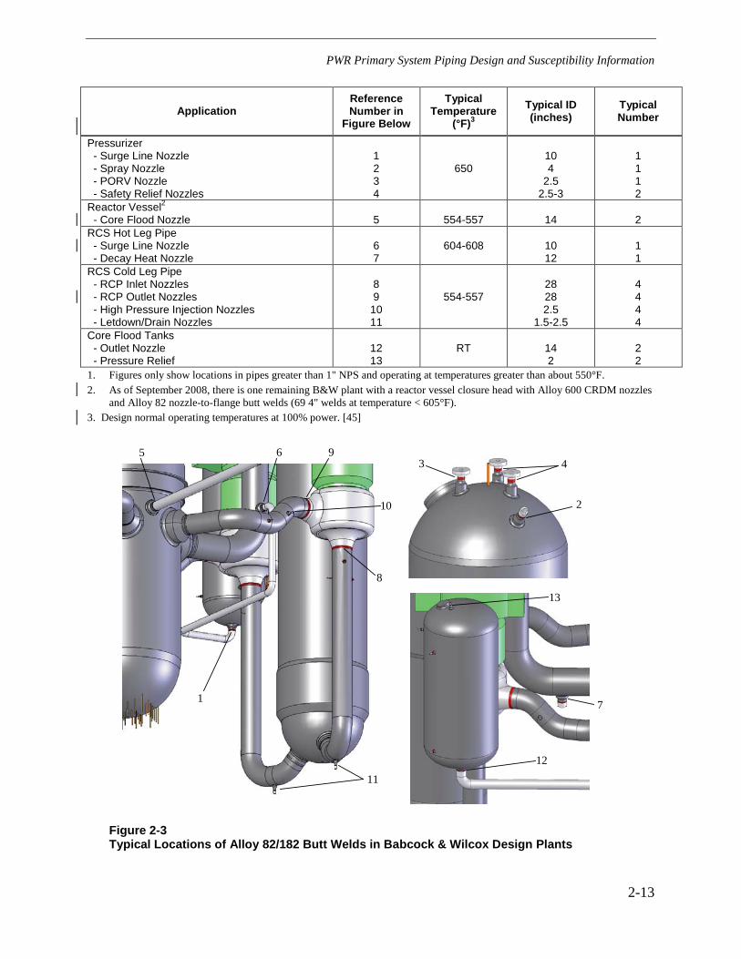
2.4 Locations in B&W Design Plants
Locations and details of Alloy 82/182 butt welds in B&W design plants are provided in the AREVA safety assessment [2] and are summarized in Figure 2-3. The primary coolant piping in B&W design plants is low-alloy or carbon steel. Therefore, the only large diameter Alloy 82/182 butt welds are between the cold leg pipes and the stainless steel reactor coolant pump casings.
The core flood lines are stainless steel, and there are Alloy 82/182 butt welds where these lines enter the RPV. This location operates at cold leg temperatures. There are Alloy 82/182 butt welds at the inlet to each of the two core flood tanks and at core flood tank pressure relief nozzles. However, these butt welds operate at essentially room temperature and are not considered further in this I&E guideline.
Most branch lines to the primary coolant piping are stainless steel, and there are Alloy 82/182 butt welds at the connection nozzles. This leads to a large number of smaller diameter Alloy 82/182 butt welds at the hot leg and cold leg piping branch nozzles.
The only other typical Alloy 82/182 pipe butt welds greater than or equal to 1” NPS, and operating at cold leg temperature and above, are between the pressurizer and the stainless steel surge, spray, and safety/relief valve lines although additional plant-specific locations may exist.
2.5 Locations with Alloy 600 Safe Ends
There are two concerns at locations with Alloy 600 safe ends or pipes. First, experience at Palisades and the Navy Advanced Test Reactor (ATR) has shown the potential for through-wall circumferential cracks in the heat-affected zone of the Alloy 600 base metal. Second, if axial

PWR Primary System Piping Design and Susceptibility Information
2-3
cracks develop in the Alloy 82/182 butt welds, the cracks can continue to propagate into the Alloy 600 base metal rather than arresting as would be the case for welds to low-alloy steel nozzles or stainless steel (SS) components. A survey of plant designs [1, 2] only identified locations with Alloy 82/182 butt welds to Alloy 600 safe ends in sizes greater than or equal to 1” NPS, and which operate at cold leg temperatures or higher, as the pressurizer spray nozzles in B&W design plants and several nozzles at Palisades. However, additional plant-specific locations may exist and their identification is each utility’s responsibility. At the pressurizer spray nozzle safe ends in B&W design plants, the critical length of through-wall axial flaws is greater than the combined length of the Alloy 82/182 butt welds and the Alloy 600 safe end such that there is no risk of rupture. Any crack growth would slow when the crack reaches lower stressed regions, away from the welds. Cracking at these locations would be captured in the examination volume of interest.
2.6 Susceptibility Information
The following is a brief discussion of causes of PWSCC crack initiation in Alloy 82/182 butt welds, crack growth rates in Alloy 82/182 weld metal, the role of several key design and fabrication-related factors on crack initiation and growth, welding residual and operating stresses in Alloy 82/182 butt welds, and preferred flaw orientation.
2.6.1 Crack Initiation: Material Susceptibility, Tensile Stress, and Environment
As has been documented in many sources, nickel-chromium-iron Alloy 600/82/182 materials are susceptible to PWSCC in PWR plant primary coolant environments. Three factors must occur simultaneously for PWSCC to occur. These factors are discussed in the following sections.
2.6.1.1 Susceptible Material
Extensive work has been performed to determine the factors that affect PWSCC susceptibility of Alloy 600 base metals. This work has shown that two main factors are chromium content and annealing temperature. Specifically, to achieve good resistance to PWSCC, the annealing temperature must be high enough to result in carbides being deposited predominantly at the grain boundaries rather than distributed throughout the grains.
Laboratory test work by Bettis and KAPL has shown that, while the material microstructure is significantly different, Alloy 82 weld metal has about the same susceptibility to PWSCC as Alloy 600 base metal [3,4], assuming identical test conditions. Electricité de France (EdF) and Framatome conducted a comprehensive series of tests of weld alloys with chromium contents ranging from 14% to 30% [5]. The results of the four types of tests (bend tests in doped steam, constant extension rate tests, or CERTs, in primary water, reverse U-bends, or RUBs, in primary water, and constant load tests in primary water) were consistent and showed that susceptibility to PWSCC decreased as chromium content increased. This suggests that Alloy 182 (Cr 13-17%) will be more susceptible to PWSCC than Alloy 82 (Cr 18-22%) and Alloy 600 (Cr 18-20% ).

PWR Primary System Piping Design and Susceptibility Information
2-4
In summary, Alloy 82 and 182 weld metals are known to be susceptible to PWSCC based on laboratory tests and previously summarized field experience, with Alloy 182 material being the most susceptible of the three due to its lower chromium content. The ability to distinguish the presence of Alloy 82 or 182 may be difficult based on available plant information.
2.6.1.2 Tensile Stress
Sustained high tensile stresses are required for PWSCC. There are two main sources of tensile stress: 1) operating condition stresses due to pressure, temperature, and other mechanical loads and 2) weld residual stress. Operating pressure, operating temperature, and external piping loads produce primary and secondary stresses. These stresses are included in the plant design calculations and must be maintained within the specified ASME Code Section III allowables. However, higher stresses are typically created during fabrication by shrinkage forces that develop as the weld cools. Welding stresses, commonly called welding residual stresses, are typically higher than the operating stresses and tend to be the dominant driving force for PWSCC initiation and crack growth. Welding residual stresses are not addressed in ASME Code Section III stress limits, but are addressed in Section XI.
For a typical PWR plant butt weld that is formed by application of weld beads from the outside surface, finite element stress analyses show high tensile hoop stresses in the outer part of the weld and lower hoop stresses approaching the inside surface. Axial tensile stresses also can develop on the inside surface. However, the magnitude of axial stresses tends to be relatively low in tension or compression in PWR welds that typically have a small diameter to thickness (D/t) ratio.
Paragraph 2.6.4 provides further discussion of welding residual and operating stresses in typical Alloy 82/182 butt welds, including the potentially detrimental effect of weld repairs.
2.6.1.3 Environment
Experience has shown that the water chemistry and temperature in PWR plant primary coolant systems contribute to PWSCC. The general experience is that, for materials of equal PWSCC susceptibility with equal applied tensile stress, the time to crack initiation is a function of operating temperature. Locations that operate at higher temperatures, such as in pressurizers, typically exhibit cracking sooner than locations that operates at lower temperatures, such as in the reactor coolant system (RCS) cold legs. For typical PWR plant pressurizer (653ºF), hot leg (600ºF), and cold leg (550ºF) temperatures and a thermal activation energy of 50 kcal/mole for crack initiation, the multipliers on time to PWSCC for hot leg and cold leg locations relative to pressurizer locations are 7.7 and 63.7, respectively. If predictions are based on crack growth rate data, the activation energy can be taken as 31 kcal/mole and the corresponding multipliers on time are 3.5 and 13.1, respectively.
While the primary coolant hydrogen and lithium concentrations can affect crack initiation and growth, studies have shown only a small effect over the ranges through which these parameters can be adjusted within the EPRI Primary Water Chemistry Guidelines [6]. Zinc addition, on the

PWR Primary System Piping Design and Susceptibility Information
2-5
other hand, has been used in a few plants and appears to have a beneficial effect to reduce PWSCC crack initiation. Zinc addition may be used in more plants in the future as a PWSCC remedial measure, including Alloy 82/182 butt welds, and as a means of reducing radiation exposure during refueling outages once more research is completed and plant data is evaluated.
2.6.2 Crack Growth Rates
MRP recently developed a deterministic crack growth model for Alloy 82/182 weld metal materials based on a statistical evaluation of the worldwide set of available laboratory test data for these materials using controlled fracture mechanics specimens [27]. Similar to the process used by MRP to develop a deterministic crack growth rate equation for Alloy 600 base metal [8], MRP screened test procedures, reviewed test results, produced a statistical model, and developed a recommended deterministic equation. An international panel of experts convened by EPRI provided detailed input to MRP during its evaluations of Alloy 600 and Alloy 82/182.
The general form of the MRP equation for Alloy 82/182 weld metal is as follows:
1 1exp galloy orient
ref
Qa f f K
R T Tβα
= − −
where:
a = crack growth rate at temperature T in m/s (or in/h)
Qg = thermal activation energy for crack growth = 130 kJ/mole (31.0 kcal/mole) R = universal gas constant = 8.314×10⁻³ kJ/mole-K (1.103×10⁻³ kcal/mole-°R) T = absolute operating temperature at location of crack, K (or °R) Tref = absolute reference temperature used to normalize data = 598.15 K (1076.67°R) α = power-law constant
= 1.5×10⁻¹² at 325°C for a in units of m/s and K in units of MPa√m (2.47×10⁻⁷ at 617°F for a in units of in/h and K in units of ksi√in)
falloy = 1.0 for Alloy 182 and 1/2.6 = 0.385 for Alloy 82 forient = 1.0 except 0.5 for crack propagation that is clearly perpendicular to the
dendrite solidification direction K = crack tip stress intensity factor, MPa√m (or ksi√in) β = exponent

PWR Primary System Piping Design and Susceptibility Information
2-6
= 1.6
For comparison, earlier data in MRP-21 [7] for Alloy 182 weld metal was based on a smaller set of data available at the time and did not result from a systematic statistical assessment. Note that unlike the earlier MRP-21 curve, the apparent stress intensity factor threshold for the new MRP deterministic model [27] is taken as zero, meaning that crack growth is assumed to occur whenever the crack tip stress intensity factor is positive.
2.6.3 Effect of Design and Fabrication Practices on Initiation and Growth
Several design and fabrication practices have an apparent effect on crack initiation and growth in Alloy 82/182 butt welds. These are as follows:
2.6.3.1 Welding Processes and Material
Alloy 82 weld metal is uncoated wire that is used for manual or machine gas tungsten arc welding (GTAW) with a cover gas. Alloy 182 weld metal is supplied in the form of coated electrodes used for shielded-metal arc welding (SMAW). A main chemical composition difference between these two materials is that Alloy 82 material has 18-22% chromium and Alloy 182 material has 13-17% chromium. The higher chromium content of Alloy 82 material results in better resistance to PWSCC initiation and crack growth as noted in Paragraph 2.6.1.1.
Alloy 182 buttering was applied to the low-alloy steel nozzle or pipe, the buttering received a post weld heat treatment (PWHT) with the low-alloy steel component, then the final Alloy 82 or 182 weld was made to the stainless steel pipe or safe end. This design eliminated the need to stress-relieve the low-alloy or carbon steel nozzle/pipe after welding to the process pipe and avoided exposing the stainless steel material to PWHT temperatures where it could become sensitized. There were some variations of this basic configuration, especially for the case of reactor-vessel-nozzle-to-pipe welds in Westinghouse plants, and they are discussed in supporting nuclear seam supply system (NSSS) specific documents.
In most cases, the buttering was applied manually using the SMAW process with Alloy 182 weld metal. The butt weld root passes, and often 2 or 3 hot passes, were typically applied using manual or machine GTAW with Alloy 82 filler metal. The welds were then completed using the manual SMAW process with Alloy 182 filler metal in earlier plants or by GTAW using Alloy 82 filler metal in some later plants. Alloy 132, which has the same chromium content as Alloy 182, was used for the butt weld, including the repair in contact with the fluid, in the Tsuruga 2 pressurizer relief valve nozzle butt weld that developed a leak. For purposes of this guideline, Alloy 132 is treated as Alloy 182.
Based on the above, most Alloy 82/182 butt welds are expected to have at least some Alloy 182 weld metal in contact with the primary coolant where it can lead to PWSCC crack initiation. For example, most welds containing Alloy 82 weld root passes, or completed using automated Alloy 82 machine welds, will still have some exposed Alloy 182 weld metal in the buttering.

PWR Primary System Piping Design and Susceptibility Information
2-7
2.6.3.2 Weld Repairs
The Alloy 82/182 butt welds were inspected, and repaired if necessary, during fabrication. One of the supporting documents to the summary safety assessment report cites several repair scenarios [24]. Weld repairs can be performed from the inside surface or the outside surface. It is interesting to note that the two cases involving leaks from Alloy 82/132/182 butt welds (V.C. Summer and Tsuruga 2) and the 45% through-wall axial flaw at TMI-1 involved extensive weld repairs.
In many cases, plants do not have information on the actual repairs—inside diameter (ID) or outside diameter (OD) repairs—performed to Alloy 82/182 butt welds. However, some plants that do have these records indicate that repairs were common, including some welds being repaired multiple times, and that some repairs had a significant circumferential length. Weld repairs to the inside surface after completion of the full weld from the outside can result in high inside surface tensile residual stresses. However, from a practical standpoint, these types of repairs are not considered to have been widespread on welds less than 4” NPS due to the limited access from the inside. DM welds 4” NPS and larger, which are most likely to have had repairs to the inside surface, also are required to receive volumetric examinations at 10-year intervals per Section XI of the ASME Code unless the examination was eliminated as part of a RI-ISI program.
2.6.3.3 Machining Inside Surface After Welding
Some pressurizer surge line nozzles and nozzles with lesser diameters were machined on the inside surfaces after welding. This machining has the potential to remove crack starters at the weld root and improve inspectability. However, cold work due to machining on the inside surface and the heat input from turning operations can result in tensile residual stresses in the cold-worked material. The cold work and tensile residual stresses due to machining are typically limited to a shallow depth (typically 0.01” or less).
While machining can cold work the surface and create local tensile residual stresses, the resultant stress intensity factor may be too low to result in significant crack growth once the crack grows out of the cold worked layer.
It should be noted that this situation at the root of the butt weld, involving machining after welding, is significantly different from that in CRDM and bottom mounted instrumentation (BMI) nozzles where material is first cold worked to final dimensions by machining and then subjected to high strain during the J-groove welding process.
2.6.3.4 Welding and Grinding on Inside Surface
Fabrication records show that some larger size hot and cold leg piping butt welds were back-gouged on the inside surface and then welded and ground again on the ID surface. Welding on the ID surface after completion of the entire weld has potential to increase the inside surface tensile stresses and, thereby, increase potential for PWSCC. Further, grinding at this location could result in initiation sites due to the cold work and high thermally induced surface residual stresses.

PWR Primary System Piping Design and Susceptibility Information
2-8
2.6.4 Welding Residual and Operating Stresses
Weld residual stress measurements and studies have been performed to understand the potential for crack initiation and growth in Alloy 82/182. Studies also have been performed for cases of weld repairs of DM butt welds [9]. Results of these studies indicate that weld repairs can have a significant impact on the resulting residual stress and, in fact, cause a more severe condition with respect to crack initiation and propagation.
Results show that maximum hoop stresses typically exceed maximum axial stresses and that a weld repair to the ID surface after completing the main weld significantly increases both the axial and hoop stresses on the ID surface. Results also show that the significant increase in weld residual stress caused by weld repairs is typically limited to the region of the weld repair.
The general behavior of these stresses is expected to have a major influence on the flaw orientation as discussed further in the following section.
2.6.4.1 Flaw Orientation: Axial vs. Circumferential
Flaw orientation is a key factor in butt weld safety evaluations. In particular, axial flaws, which are limited to the width of the Alloy 82/182 weld metal, arrest when they reach low-alloy and stainless steel materials at each end. This has been confirmed by experience at V.C. Summer and Tsuruga 2 and also at Ringhals and TMI-1. It is noted that self-arrest at the weld interface does not occur for the case of Alloy 600 pipe or safe ends. Crack extension into the pipe or safe end cannot be ruled out.
Through-wall, part-circumferential flaws, although not yet seen to date in Alloy 82/182 weld metal in PWRs, can potentially grow to significant size before leakage would be detected by traditional online detection methods such as inventory balances. In most cases, significant structural margin exists even at the leak detection threshold [20]. Leakage associated with the critical size was greater than the maximum technical specification allowed leakage for all locations except one small diameter location.
Part-depth, 360º circumferential flaws, if they were to grow to significant depth, could pose a probability of rupture under upset conditions without advanced warning provided by leakage. Therefore, these flaws would pose the greatest safety concern.
The purpose of the following paragraphs is to review available information relating to possible flaw orientations. [The field experience cited in these sections was current in summer 2004. Subsequent field experience is summarized in Section 4.4, “MRP-139 Examination Results through 2007 Refueling Outages.”]
2.6.4.1.1 PWR Field Experience
Cracking of Alloy 82/182 butt welds in PWR plants has been limited to V.C. Summer, Ringhals 3, Ringhals 4, Tsuruga 2, TMI-1, and possibly Tihange. All indications have been axial with the

PWR Primary System Piping Design and Susceptibility Information
2-9
exception of a short (2-inch-long), shallow (≅ 0.2-inch-deep) circumferential crack in Alloy 182 of the same leg that had an axial flaw and leaked at V.C Summer. The shallow circumferential crack arrested when it reached the low-alloy steel nozzle base metal [20].
There have been two cases of part-circumferential flaws that extend through-wall in the weld-heat-affected zone of Alloy 600 base metal (Palisades [31] and ATR[32]).
2.6.4.1.2 BWR Field Experience
BWR plants experienced SCC of piping early in plant life, and flaw orientations can shed some light on the potential for circumferential cracks to develop in PWR-plant Alloy 82/182 butt welds.
MRP-57 [10] summarizes the cracking experience in BWR piping. The BWR data show that axial cracks can grow to significant length if not arrested by some resistant material transition such as low-alloy or stainless steel for the case of PWSCC in PWR plants. The data show that most circumferential flaws had arc lengths less than approximately 60º. Part-circumference weld repairs may be a contributing factor to this length. Some of these BWR circumferential flaws were associated with geometric features such as backing bars, which are unlikely to exist in PWRs.
The case of the 360º part-depth crack at Duane Arnold, a BWR, which also leaked, has received significant attention and is often used as an example of why 360º part-depth cracks cannot be ruled out [11]. Crack initiation and growth were attributed to the presence of a fully circumferential crevice that led to development of an acidic environment in the presence of oxygen or an oxidizing species in the normal BWR water chemistry. This set of circumstances was combined with high residual and applied stresses as a result of the geometry and nearby welds. The conditions that occurred at Duane Arnold do not apply for the case of Alloy 82/182 butt welds in PWR plants [20, 24].
2.6.4.1.3 Finite Element Stress Analysis
Finite element modeling shows that hoop stresses are predicted to exceed axial stresses at high-stress locations on the inside surface such that most cracks would be expected to be axially oriented. These results also show that through-wall stress distributions favor growth of axially oriented cracks such as those discovered at Ringhals, VC Summer, Tsuruga 2, and TMI-1. However, the analysis results show locations of high axial stress on the inside surface for the case of repaired welds that could possibly support initiation of circumferential cracks.
In summary, this review of PWR field experience, BWR field experience, and finite element stress analysis results suggests that most PWSCC flaws in Alloy 82/182 butt welds are likely to be axially oriented. Additional work on this subject has shown that deep circumferential flaws are likely to be limited to the arc length corresponding to repairs from the inside surface or the area affected by deep repairs from the outside surface.

PWR Primary System Piping Design and Susceptibility Information
2-10
Table 2-1 Locations Involving Alloy 82/182 Pipe Butt Welds1
Location Westinghouse Design Plants
Combustion Engineering
Design Plants
Babcock & Wilcox Design
Plants
Reactor Vessels
- Inlet & Outlet Nozzles
- Core Flood Nozzles
Yes
N/A
No2
N/A
No
Yes
Pressurizers
- Surge Line Nozzles
- Spray Nozzles
- Safety & Relief Valve Nozzles
Yes
Yes
Yes
Yes
Yes
Yes
Yes
Yes
Yes
RCS Piping Loop
- SG Inlet & Outlet Nozzles
- RCP Suction & Discharge Nozzles
No4
No
No4
Yes3
No
Yes
RCS Branch Line Connections
- HL Pipe to Surge Line Connection
- Charging Inlet Nozzles
- Safety Injection and SDC Inlet
- Shutdown Cooling Outlet Nozzle
- Pressurizer Spray Nozzles
- Let-Down and Drain Nozzles
No
No
No
No
No
No
Yes
Yes
Yes
Yes
Yes
Yes
Yes
Yes
Yes
Yes
Yes
Yes
1. Table does not include butt welds in instrument nozzles 1” NPS and smaller or welds that operate at less than 550°F (CRDM nozzle to flange butt welds, BMI nozzle to pipe butt welds, core flood tank nozzle butt welds) which are out of scope for this document.
2. One CE design plant has Alloy 82/182 welds and is evaluated with the Westinghouse design plants. 3. One CE design plant does not have Alloy 82/182 RCP suction and discharge nozzle welds. 4. One Westinghouse design plant and one CE design plant have Alloy 82/182 butt welds at this location.

PWR Primary System Piping Design and Susceptibility Information
2-11
Application
Reference Number in
Figure Below
Typical Temperature
(°F)
Typical ID (inches)
Typ. Number (3 Loop Plant)
Pressurizer - Surge Line Nozzle - Spray Nozzle - Safety/Relief Nozzles
1 2 3
653
10 4 5
1 1 4
RCS Hot Leg Pipe
- Reactor Vessel Outlet Nozzles3
- Steam Generator Inlet Nozzles4
4 5
600-620
29 --
3 --
RCS Cold Leg Pipe
- Steam Generator Outlet Nozzles4 - Reactor Vessel Inlet Nozzles3
6 7
550-560
--
27.5
-- 3
1. Figures only show locations in pipes greater than 1" NPS and operating at temperatures greater than about 550°F. 2. Plants with original reactor vessel closure heads have CRDM nozzles with Alloy 82/182 nozzle-to-flange butt welds (4"
diameter). 3. There are no Alloy 82/182 RPV nozzle welds in Westinghouse 2-loop plants and some early Westinghouse
3-loop and 4-loop plants. 4. One plant has Alloy 82/182 butt welds between the reactor coolant piping and steam generator nozzles.
2
6
4 3
1
7
5
3
Figure 2-1 Typical Locations of Alloy 82/182 Butt Welds in Westinghouse Design Plants

PWR Primary System Piping Design and Susceptibility Information
2-12
Application Reference Number in
Figure Below
Typical Temperature
(°F)
Typical ID (inches)
Typical Number
Pressurizer - Surge Line Nozzle - Spray Nozzle - Safety/Relief Nozzles
1 2 3
643-653
10 3 5
1 1
2-3 RCS Hot Leg Pipe - Surge Line Nozzle - Shutdown Cooling Outlet Nozzle - Drain Nozzle
4 5 6
600
10 10 2
1 1 1
RCS Cold Leg Pipe - RCP Inlet Nozzles - RCP Outlet Nozzles - Safety Injection - Pressurizer Spray Nozzles - Letdown/Drain Nozzles - Charging Inlet Nozzle
73 83 9
10 11 12
549-560
30 30 10
2.25 1.3 1.3
4 4 4 2 44 2
1. Figures only show locations in pipes greater than 1" NPS and operating at temperatures greater than about 550°F. 2. Some plants with original reactor vessel closure heads have CEDM/ICI nozzles with Alloy 82/182 nozzle-to-flange butt
welds. 3. One plant does not have Alloy 82/182 welds at reactor coolant pump. 4. One plant has 8 cold leg letdown/drain nozzles.
2
3
10
12
4
7
8
5
9
1
6
11
Figure 2-2 Typical Locations of Alloy 82/182 Butt Welds in Combustion Engineering Design Plants
PWR Primary System Piping Design and Susceptibility Information
2-13
Application Reference Number in
Figure Below
Typical Temperature
(°F)3
Typical ID (inches)
Typical Number
Pressurizer - Surge Line Nozzle - Spray Nozzle - PORV Nozzle - Safety Relief Nozzles
1 2 3 4
650
10 4
2.5 2.5-3
1 1 1 2
Reactor Vessel2 - Core Flood Nozzle
5
554-557
14
2
RCS Hot Leg Pipe - Surge Line Nozzle - Decay Heat Nozzle
6 7
604-608
10 12
1 1
RCS Cold Leg Pipe - RCP Inlet Nozzles - RCP Outlet Nozzles - High Pressure Injection Nozzles - Letdown/Drain Nozzles
8 9
10 11
554-557
28 28 2.5
1.5-2.5
4 4 4 4
Core Flood Tanks - Outlet Nozzle - Pressure Relief
12 13
RT
14 2
2 2
1. Figures only show locations in pipes greater than 1" NPS and operating at temperatures greater than about 550°F. 2. As of September 2008, there is one remaining B&W plant with a reactor vessel closure head with Alloy 600 CRDM nozzles
and Alloy 82 nozzle-to-flange butt welds (69 4" welds at temperature < 605°F). 3. Design normal operating temperatures at 100% power. [45]
1
5
8
63
2
9
10
4
13
12
11
7
Figure 2-3 Typical Locations of Alloy 82/182 Butt Welds in Babcock & Wilcox Design Plants


3-1
3 SUMMARY OF PWSCC MITIGATION PROCESSES
This section discusses various approaches for mitigating PWSCC. While section 2.0 discussed factors that contribute to susceptibility of weldments to PWSCC, this section discusses specific methods to modify the material, environment, or stress condition of susceptible locations. To date, there have been several approaches to mitigate SCC, especially in BWRs. These include stress improvement (SI) processes such as the induction heating stress improvement (IHSI) process and Mechanical Stress Improvement process (MSIP™); environment changes or controls such as hydrogen water chemistry (HWC) and noble metal chemical (NMC) addition in BWRs; and material changes such as replacement of susceptible piping with more resistant piping or with resistant weld metal.
The intent of this section is not to provide all details regarding mitigation, but to identify what a mitigation measure must accomplish to be considered fully effective. As will be presented later in section 5, the frequency of examination of primary system welds is a function of whether the weldment has been subjected to a mitigative process. Significant credit is provided for those locations that have been treated with some type of mitigation.
3.1 Mitigation by Modification of Materials
PWSCC-resistant material is considered to include austenitic stainless steels, cast stainless steels, and high nickel alloy materials with nominally 30% Cr. Resistant welding materials include Alloy 52 and Alloy 152. To change a PWSCC-susceptible weldment to a PWSCC-resistant weldment, the non-resistant material must be replaced or totally isolated from the primary water/steam environment. For example, weld inlay (cladding on inside pipe surface) made from Alloy 52 that covers all Alloy 182 exposed to the primary coolant would be considered an effective PWSCC-mitigative measure.
Application of a full structural weld overlay also introduces a resistant material if it is made from PWSCC-resistant material such as Alloy 52. Although the susceptible material remains exposed to the primary coolant (since the weld overlay is applied to the outside surface of the weld) and may contain a crack, the thickness of the overlay is sufficient to meet required ASME Code safety factors without taking credit for the original pipe wall. If the crack were through the original wall, the inside diameter of the weld overlay would be exposed to the environment. However, since Alloy 52 is resistant to PWSCC, cracking would be considered mitigated. Note also that structural weld overlays also act as an SI process, subjecting the inner portion of the pipe to compressive stress due to shrinkage as the weld cools.
Replacement of PWSCC-susceptible material with PWSCC-resistant material, including the weld metal, also would be considered an acceptable mitigation for the particular weld location.

Summary of PWSCC Mitigation Processes
3-2
3.2 Mitigation by Stress Improvement
Various SI processes have been used, especially in BWRs, and are currently available. Those mitigation techniques mentioned in this report are not intended to be the only acceptable methods. Other methods may be used if they are demonstrated to meet the requirements listed in the discussion below.
3.2.1 SI of Uncracked Weldments
To be considered an effective PWSCC mitigation process, the SI process must significantly modify the residual stress field at the weld location. For the uncracked weld condition, this is accomplished by producing sufficient compressive stress on the ID wetted surface such that, when sustained operating loads are added, the stress on the inside pipe surface remains compressive. The presence of the compressive stress inhibits initiation and propagation of PWSCC.
Historically, SI must be followed by qualified volumetric or surface examination(s) [33] to be fully credited as a mitigative measure. If cracks are found, they must be sized both in depth and length by procedures and personnel qualified to perform sizing evaluations. If cracks are found, they would be reevaluated according to the following discussion (section 3.2.2) regarding cracked piping subjected to SI.
Examples of qualified SI that have been applied in light water reactors (LWRs) include
• MSIP™;
• WOL – weld overlay; stress improvement only (design weld overlays);
• WOL – weld overlay; structural overlay;
• IHSI; and
• heat sink welding (HSW) (for small diameter piping).
Other SI processes such as surface conditioning (burnishing, laser peening) can be used as they become available and qualified (if they can be shown to develop sufficient compressive residual stress such that compressive stress exists on the inside surface during normal operation).
3.2.2 SI of Cracked Weldments
SI of cracked components also can be considered an effective mitigation process when applied to weldments with short or shallow cracks. Specifically, welds with cracks that are no longer than 10% of the circumference and no deeper than 30% of the wall thickness can be considered to be mitigated by an effective SI [22, 30]. The requirement for the SI process to be effective on a cracked component is that the stress intensity factor must be negative at the crack tip. The stress intensity factor must include residual stress and all sustained operating loads (primary and secondary). SI effectiveness also must be shown on a weld repaired as-welded condition unless it can be definitively shown that no weld repairs exist. Additional margins (for flaws larger than

Summary of PWSCC Mitigation Processes
3-3
10% of circumference or 30% of the wall thickness) may be demonstrated by performing component-specific analytical or experimental evaluations.
As mentioned in section 3.2.1 for uncracked weldments, historically the SI process must be followed by a qualified UT examination [33] to be fully credited as a mitigative measure. If cracks are found by this examination, they must be sized both in depth and length by procedures and personnel qualified to perform sizing evaluations.
The full structural weld overlay (FSWOL) and optimized weld overlay (OWOL) are special cases of an SI process, due to the fact that they provide both residual stress improvement and weld reinforcement with PWSCC resistant material. Since it replaces fully the underlying cracked component, the FSWOL mitigation measure can be used under conditions where very deep, long cracking exists in the component being overlay repaired (theoretically, 100% through wall and 360° around the original weld). OWOLs replace a portion of the underlying cracked component, and their use for repairs is limited to cracks no greater than 50% through-wall and 360° around the original weld. Additional details regarding application of full structural and optimized weld overlays are presented in section 6.0.
Other SI processes may be considered as they become available. These SI processes must be able to produce a negative stress intensity factor at the crack tip during normal operating conditions to be considered effective.
3.3 Mitigation by Environment
Mitigation can be obtained by implementing changes to the operating environment that reduces the material’s susceptibility to PWSCC. The following represent some of the approaches that are being considered to mitigate this susceptibility. It should be noted that other methods may be used as they become available if they can be technically justified. The effectiveness of the processes described in this section for PWSCC mitigation will be evaluated on completion of the respective studies.
It also should be noted that the examination requirements in section 6.0 of this guideline do not currently consider credit for environment-based mitigation. Once environment-based mitigation processes become qualified for PWSCC, the examination recommendation should be revised.
3.3.1 Change in Electrochemical Potential (ECP)
The ECP of a material in an environment strongly affects its response to the corrosive effects of that environment. In particular, the PWR environment produces a corrosion potential for nickel base alloys that is very reducing (typically lower than -750mV standard hydrogen electrode, or SHE) [29]. Below these potentials, susceptibility to PWSCC has been observed in nickel alloys. Several investigators have demonstrated that elevating ECP (making it more anodic) by several hundred millivolts can decrease the susceptibility of nickel alloys in the PWR environment. To this end, MRP has initiated a study investigating anodic protection for these alloys in the PWR primary environment.

Summary of PWSCC Mitigation Processes
3-4
3.3.2 Zinc Addition
Zinc addition to BWRs has been demonstrated to be effective in reducing susceptibility to IGSCC of austenitic materials [26, 28]. A similar measure has been proposed to mitigate PWSCC in nickel base alloys by adding zinc to the primary coolant. Laboratory tests have demonstrated that zinc appears to extend the time to crack initiation and may retard crack propagation rates of active PWSCC. MRP is conducting studies to evaluate the effectiveness of zinc on PWSCC of these alloys and also will establish effectiveness parameters. The effectiveness of zinc as a PWSCC mitigation measure awaits the outcome of these studies.
3.3.3 Temperature
Temperature is one of the important factors affecting PWSCC of nickel alloys. Elevating temperature has a deleterious effect on PWSCC of nickel alloys. One consideration in the PWR industry for ranking relative susceptibility of a component or system to PWSCC has been the system’s operating temperature. Temperature effects on both initiation and growth appear to follow an Arrhenius relationship (exponential relationship) for these alloys.
While reducing the operating temperature may have a positive effect on PWSCC of these alloys, the economic impact on reduced power may argue against this potential mitigation approach.
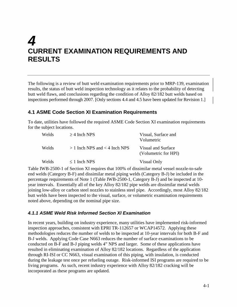
4-1
4 CURRENT EXAMINATION REQUIREMENTS AND RESULTS
The following is a review of butt weld examination requirements prior to MRP-139, examination results, the status of butt weld inspection technology as it relates to the probability of detecting butt weld flaws, and conclusions regarding the condition of Alloy 82/182 butt welds based on inspections performed through 2007. [Only sections 4.4 and 4.5 have been updated for Revision 1.]
4.1 ASME Code Section XI Examination Requirements
To date, utilities have followed the required ASME Code Section XI examination requirements for the subject locations. Welds ≥ 4 Inch NPS Visual, Surface and
Volumetric
Welds > 1 Inch NPS and < 4 Inch NPS Visual and Surface (Volumetric for HPI)
Welds ≤ 1 Inch NPS Visual Only Table IWB-2500-1 of Section XI requires that 100% of dissimilar metal vessel nozzle-to-safe end welds (Category B-F) and dissimilar metal piping welds (Category B-J) be included in the percentage requirements of Note 1 (Table IWB-2500-1, Category B-J) and be inspected at 10-year intervals. Essentially all of the key Alloy 82/182 pipe welds are dissimilar metal welds joining low-alloy or carbon steel nozzles to stainless steel pipe. Accordingly, most Alloy 82/182 butt welds have been inspected to the visual, surface, or volumetric examination requirements noted above, depending on the nominal pipe size.
4.1.1 ASME Weld Risk Informed Section XI Examination
In recent years, building on industry experience, many utilities have implemented risk-informed inspection approaches, consistent with EPRI TR-112657 or WCAP14572. Applying these methodologies reduces the number of welds to be inspected at 10-year intervals for both B-F and B-J welds. Applying Code Case N663 reduces the number of surface examinations to be conducted on B-F and B-J piping welds 4” NPS and larger. Some of these applications have resulted in eliminating examination of Alloy 82/182 locations. Regardless of the application through RI-ISI or CC N663, visual examination of this piping, with insulation, is conducted during the leakage test once per refueling outage. Risk-informed ISI programs are required to be living programs. As such, recent industry experience with Alloy 82/182 cracking will be incorporated as these programs are updated.

Current Examination Requirements and Results
4-2
4.2 Flaw Detection Capability
The following is a summary of visual, surface and volumetric flaw detection capabilities.
4.2.1 Visual Examination
Bare metal visual inspections have proven to be a reliable method of finding small leaks from butt welds at V.C. Summer, Tsuruga 2, and other locations; CRDM nozzles; pressurizer heater sleeves; RPV bottom head nozzles; and small diameter instrument nozzles. The industry recommended in January, 2004, that all Alloy 600/82/182 pressure boundary locations be subjected to a bare metal visual examination or other equivalent examination within the next two refueling outages, with priority given to inspecting the highest temperature (pressurizer and hot leg) welds during the next outage to verify that there are no leaks [12]. This recommendation was made "needed" under the NEI 03-08 materials initiative in April 2004 [25]. Plants that have performed such an examination per MRP Letter 2004-05 during the last refueling need not repeat the examination. For plants that already have a comprehensive plan, the plan should be reviewed to ensure that the bases for the examination type and frequency remain valid and meet the intent of the industry recommendation [12, 25].
4.2.2 Surface Examination
Liquid penetrant examination of the external surface of a weld is capable of detecting through-wall flaws or outside-surface-initiated flaws. While surface examinations are capable of detecting through-wall cracks from the outside surface, visual inspections for boric acid leakage are expected to provide equally good detection of through-wall cracks. Visual, eddy current testing (ECT), or liquid penetrant examinations from the outside surface cannot detect part-through-wall PWSCC cracks or subsurface cracks.
ECT examinations of the inside surface, where PWSCC cracks initiate, are only practical on the reactor vessel inlet and outlet nozzle butt welds since the inside surfaces of most butt welds are not accessible. Through 2004, reactor vessel inlet and outlet nozzles with dissimilar metal welds at VC Summer, Catawba Unit 2, Prairie Island Unit 1, Callaway 1, and Kewaunee have been inspected all or in part by surface examination techniques from the inside surface in domestic PWR plants. No crack-like indications were identified.
4.2.3 Volumetric Examination: Experience Prior to About 1990
All dissimilar metal welds, including those containing Alloy 182 in categories B-F and B-J, have been volumetrically examined every 10 years, following the requirements of ASME Section XI. Ultrasonic examination methods are used predominantly for this examination. Radiography also has been used, but not as extensively as UT. Dissimilar metal welds pose an examination challenge due to the microstructure of the weld combined with access constraints and weld geometry features.
The need for improving ultrasonic examination technology for austenitic piping, including DM weldments, multiple material types, and microstructures in the scan path, became evident during the early 1980s when extensive stress corrosion cracking was discovered in BWR stainless steel

Current Examination Requirements and Results
4-3
piping systems [13]. In many cases, piping welds that had passed examination leaked very soon afterward, showing that cracks could escape detection using ultrasonic methods in practice at that time. During this same period, several international round robin exercises were completed [14] that showed large scatter in the performance among examination teams. This experience created an impetus to improve ultrasonic examination technology. Also at this time, formal requirements for demonstrating the performance of examination procedures and personnel came into effect, but only for BWR piping inspections. The BWR piping examination [15] experience spurred improvements of UT instrumentation, procedures, and personnel training and performance was formally assessed and documented. Since no instances of similar cracking had been reported in PWR units, there was no corresponding effort to demonstrate performance for PWR piping examination at that time [16]. However, UT technology improvements that came from the BWR experience contributed to improving the technology applied to PWR units, although there were no regulatory requirements at the time to demonstrate capability for PWR applications [17].
4.2.4 Volumetric Examination: Improvements After 1990
General performance demonstration requirements first appeared as Appendix VIII to the 1989 Addenda of Section XI of the ASME Boiler and Pressure Vessel Code [14]. Appendix VIII requires demonstration of the capability to detect, discriminate, and size defects by examining realistic mockups containing intentional defects with well-known size and location. Essential variables used in the performance demonstrations were recorded and have become part of the qualification record. Supplements in Appendix VIII address specific components such as piping welds, vessel welds, vessel nozzles, and bolting. Supplement 10 of Appendix VIII addresses UT of dissimilar metal welds and was incorporated into 10 CFR50.55a, requiring implementation by November 22, 2002. All dissimilar metal weld examinations after that date have been required to be performed with Appendix VIII qualified procedures and personnel. Thus, incorporation of Supplement 10 into the rule introduced formal performance demonstration requirements for PWR and BWR piping DM weld inspections.
Discovery of a leak from the VC Summer hot leg weld in 2000, and the associated UT and ECT experience, showed that the geometry of the weld can dramatically affect the reliability of UT for examinations conducted from the inside surface of the pipe. Other experience, including Supplement 10 qualification results, confirmed the importance of knowing the weld configuration to enable adequate preparation for the examination. For examinations performed from the outside surface, the weld and nozzle geometry, and the roughness or waviness of the surface, have a particularly strong influence on examination effectiveness.
The industry responded to these events with further improvements of UT technology coupled with intense efforts to qualify procedures and personnel to Supplement 10 for PWR applications. The qualification to Supplement 10 was modified to include challenging weld configurations such as were encountered at VC Summer to ensure that procedures and tooling address the range of inside surface contours. These experiences have identified the most effective techniques and practices, and these practices have been incorporated into production examination procedures [18]. In many situations, procedures and equipment in place prior to Supplement 10 implementation had to be modified to improve performance to meet the new requirements. Another practical outcome of implementing Appendix VIII, in addition to documenting

Current Examination Requirements and Results
4-4
performance relative to standards, is formal documentation of procedure limitations. That is, the qualification record specifically documents the range of conditions, such as surface roughness or waviness, for which the procedure is qualified. This enables owners to identify where the procedures would not be effective and allows assessment and application of alternatives to address the limitations. This kind of formal documentation was not available prior to implementation of Appendix VIII. The most significant limitations pertain to surface conditions and weld configurations that preclude effective scanning. Owners can assess the applicability of qualified procedures only if the site-specific surface conditions and as-built weld configurations are known.
4.2.5 Volumetric Examination: Summary Status
PWR DM weld examinations conducted prior to implementing Appendix VIII were performed with a variety of techniques and with a range of effectiveness that is not possible to accurately quantify [13,18]. A review of industry experience [18] shows several instances where cracking, including circumferential cracking, escaped detection. The lack of detailed documentation of NDE capability prior to Supplement 10, coupled with the lack of detailed information on as-built weld configurations and access, makes it impossible to definitively characterize the capability of procedures applied in past examinations. Examination capability has been continually improving in response to service experience and the availability of technology innovations. Appendix VIII is the latest major improvement in a history of continuous capability improvement. Implementing Supplement 10 to Appendix VIII has resulted in development and application of improved procedures for UT detection and characterization of PWSCC in pipe butt welds. Structural integrity assessments can be made with confidence for those situations in which a qualified UT procedure can be applied.
In summary, while volumetric inspections prior to about 2002 may not have had the same detection capability or pedigree as inspections performed subsequent to implementation of Appendix VIII, Supplement 10, they have provided some assurance, in combination with the results of visual and surface examinations, that significant PWSCC is not widespread in dissimilar metal welds.
4.3 Examination Results Through Spring 2004 Refueling Outages
Alloy 82/182 butt welds in domestic PWR plants have been inspected as specified by Section XI of the ASME Code and by visual inspections for borated water leakage. As noted above, these inspections have involved visual inspections, surface examinations, and volumetric examinations. Similar inspections have been performed at PWR plants worldwide. As of the end of 2003 there have only been a small number of cases of part-through-wall axial flaws limited to the widths of the welds, two cases of leaks occurring from axial flaws, and one case involving a short, shallow circumferential flaw. The two leaks from axial flaws were detected by visual inspections for borated water leaks or in preparation for UT from the OD. None of the indications posed a safety concern at the time of detection.
Current Examination Requirements and Results
4-5
4.4 MRP-139, Rev. 1 Update - Examination Results Through 2007 Refueling Outages
Inspections performed during the first two years of MRP-139 baseline inspection implementation have included RV nozzles (in conjunction with scheduled RV 10-year ISI exams) and the pressurizer nozzles consistent with the December 31, 2007 baseline exam deadline. NDE indications associated with MRP-139 baseline exams of pressurizer nozzle welds have been reported at Farley 2 (spring 2007) and Wolf Creek (fall 2006). Certainly, the most notable are the five circumferential indications discovered in three pressurizer nozzles at Wolf Creek. These indications ranged from 8º to 166º of arc length and up to an estimated 31% through wall but no samples were taken to confirm the NDE results (UT) and the plant proceeded to install the full structural weld overlays as planned for mitigation purposes.
In fall 2007 outages in Japan at Tsuruga 2 and Mihama 2, a number of part-through wall indications with both axial and circumferential characteristics were discovered in SG nozzle to safe-end welds ultimately resulting in exam scope expansion to include all such SG nozzle welds in Japanese plants. Material samples have been removed for destructive examination and inspections are ongoing with cracks confirmed at several additional plants.
Finally, Davis Besse shut down at the end of 2007 to implement PZR and <14” hot leg DM weld overlays. During the initial weld layer to overlay the Decay Heat drop line nozzle to pipe weld, a near-through wall crack opened up and began to weep. This crack was subsequently determined through phased array UT to be axial and entirely contained within the weld/butter. The overlay was subsequently completed as a repair.
4.5 Conclusions Regarding Butt Weld Condition
The following conclusions can be drawn from the above experience: • There is potential for PWSCC of Alloy 82/182 butt welds. • A significant number of butt welds have been inspected during plant ISI programs. • Inspection capability over the past two years has improved significantly. • There is no evidence of widespread PWSCC of Alloy 82/182 butt welds at present. • Butt weld PWSCC detected to date and confirmed metallurgically has typically been
associated with significant weld repairs. • The Wolf Creek indications represent the most severe conditions attributed to butt weld
PWSCC to date. • The few locations involving Alloy 600 safe ends or nozzles will require additional attention
for two reasons. First, field experience has shown the potential for through-wall circumferential flaws in the base-metal-heat-affected zone. Second, axial cracks that initiate in Alloy 82/182 weld metal may continue to propagate into the Alloy 600 safe end. However, Alloy 600 safe ends in applications greater than 1” NPS and operating temperatures greater than 550°F are limited to pressurizer spray nozzles in B&W design plants and several nozzles in Palisades. In the case of the B&W pressurizer spray nozzle safe end or nozzle, the critical length for axial flaws is greater than the combined length of the Alloy 82/182 butt welds and the Alloy 600 safe ends.


5-1
5 EXAMINATION REQUIREMENTS
Sections 5 and 6 of this guideline provide the process for determining
• what NDE method should be used for each DM weld, • if any additional analysis is necessary based on NDE method chosen, and • what re-examination frequency is required for each DM weld.
Each owner is already required to determine whether an examination can be performed that meets the requirements of ASME Section XI Appendix VIII for dissimilar metal welds. These examinations are currently required to be completed by November 22, 2012. This I&E guideline requires that utilities conduct essentially equivalent exams earlier and more frequently than required by the current ASME Code for Alloy 82/182 butt weld locations. Depending on the amount of attainable coverage for circumferential flaws for each Alloy 82/182 butt weld, additional actions may be necessary. These actions could include degradation assessment, local leak detection, and mitigation. Re-examination frequencies are based on the type of examination performed, examination results, whether any mitigative action has been performed, and the Alloy 82/182 weld location (pressurizer, hot leg, or cold leg). Actions intended by this I&E guideline to be implemented in accordance with ASME code requirements are explicitly identified as such herein. In all other situations, the parallel authority of this document and the ASME Code relative to treatment of DM butt welds needs to be recognized. Compliance with all relevant requirements of the ASME Code and the plant's licensing basis should be ensured independent of the requirements of MRP-139.
Examination requirements include implementing the volumetric examination requirements (methods) section 5.1, visual examination requirements section 5.2, volumetric examination schedule/frequencies in Table 6-1, and visual examination schedule/frequencies in Table 6-2. The examination requirements are a subset of this I&E guideline.
This section provides the methodology for performing volumetric NDE and visual examination of DM weld locations. NDE of DM welds must be qualified to ASME Section XI Appendix VIII requirements. Meeting those requirements for some locations is difficult due to various constraints such as materials of construction, geometry, accessibility, interference from structures/fixtures that can and cannot be removed, and surface conditions. In recognition of these challenges, this section provides the methodology and process for use in performing inspections that are considered sufficient to demonstrate structural integrity. ASME Section XI, Appendix VIII, contains the methodology and criteria for qualifying ultrasonic examination procedures and personnel for certain examinations required by Section XI, including most DM butt welds. It is recognized that there are several ways to demonstrate compliance with Appendix VIII. This guideline uses examples from the industry’s Performance Demonstration Initiative

Examination Requirements
5-2
(PDI). This guideline does not require use of the PDI process; however, it does use information from the program to offer further descriptive details where useful.
This section of this I&E guideline is structured to assist users in selecting the optimum examination process and obtaining the maximum coverage possible.
Inspection Volume
Section 5.1 provides the process and methodology for NDE of DM welds. Figure 5-1 is a schematic of the methodology process. One outage prior to the volumetric examination, each owner should determine what NDE techniques are available for each Alloy 82/182 butt weld covered by the scope of this guideline. Figure 5-2 is a schematic of the minimum required volumetric examination volume for typical Alloy 82/182 butt welds. This guideline does not provide an examination volume drawing for each butt weld configuration in the PWR fleet. However, this figure can be used with the following text to define the required examination volume for Alloy 82/182 butt welds covered by this guideline. • For the purposes of meeting this guideline, the boundaries of the required examination
volume shall include the wetted surface of susceptible materials and the heat-affected zone (HAZ) of any Alloy 600 components to a depth of 1/3 of wall thickness.
• As shown in Figure 5-2, where the examination is conducted from the OD surface of the pipe (A-B), the required examination volume is shown by the area within C-D-E-F. Points E and F are 1/4” outboard of the weld (or butter) to base material fusion line as measured on the outer surface of the pipe or outboard of the associated ID extent of wetted susceptible weld material (if known), whichever is greater.
• As shown in Figure 5-2, where the examination is conducted from the ID surface of the pipe (E-F), the required examination volume is shown by the area within C-D-E-F. Points E and F in this case are 1/4” outboard of the weld (or butter) to base material fusion line as measured on the inner surface of the pipe or outboard of the associated ID extent of wetted susceptible weld material (if known), whichever is greater.
• For DM butt welds joining to cast stainless steel components (CASS), for which no ASME Section XI, Appendix VIII supplement exists, volumetric interrogation of the cast stainless steel material is not required (CASS is not known to be susceptible to PWSCC or any other service-related cracking degradation mechanism that is relevant within the RCS operating environment). [40]
• PDI-qualified examination procedures for these welds may require interrogation of an expanded examination volume up to the full thickness of the material (exceeding both the examination volume stated above and the ASME Code required examination volume in the 2004 edition and earlier) Therefore, the required inspection volume for the selected PDI procedures should be carefully reviewed to ensure compliance. Data collected beyond the inner 1/3t requirement can be analyzed to help characterize the condition of the Alloy 82/182 weld.
Since some plants have been inspected using current ASME Code Section XI examination volume requirements (Figure IWB-2500-8), these inspections may have not interrogated the entire volume as defined by this I&E guideline.

Examination Requirements
5-3
For some configurations, possibly due to joint geometry, butter thickness, or cladding using PWSCC-susceptible material, some of the examination volume defined in this guideline may not be inspected if Figure IWB-2500-8 is used. However, examinations may have included the same volume as Figure 5-2 where the interface between the weld and the butter material is not clearly distinguishable. The NDE examiner may have conservatively used the clearly distinguishable interface between butter and base material as the weld toe. Although these inspections may have not fully inspected the required volume per this guideline, it is considered acceptable to credit these earlier inspections as an adequate examination for the overall determination of the DM joint condition. The justification for this credit is provided below. 1. The ASME Code Figure IWB-2500-8 examination interrogates the welds and a significant
amount of susceptible material on the inside surface. The ASME Code examination volume coincides with the highest stress location when considering the weld residual stress. The maximum weld residual stress distribution is typically near the weld and decreases significantly with distance from the weld.
2. Although weld repairs cannot be ruled out at any PWSCC-susceptible material location, it is likely that the ASME Code examination volume would interrogate at least some portion of any repairs that might be present.
3. Any repairs made in the butter or clad would require PWHT, thus reducing the residual stress in areas that may not have been inspected with the ASME Code Section XI examination volume.
4. Although circumferential flaws cannot be ruled out, weld residual stress favors the presence of axial flaws. Since axial flaws would grow lengthwise (perpendicular to the weld) if a flaw were present, growth into the examination volume could occur.
5. The presence of circumferential flaws has been associated with the presence of axial flaws. Since an axial flaw could grow into the inspected ASME Code volume, this would indicate the potential for circumferential flaws, which are limiting with regards to structural integrity.
Based on the above discussion, previous inspections performed using ASME Code Section XI examination volumes and in compliance with Appendix VIII can be credited as an acceptable examination per this guideline. Future inspections, however, must be made using the examination volumes presented in this guideline.
5.1 Volumetric Examination Methods
5.1.1 ASME Section XI, Appendix VIII Qualified Procedures (Figure 5-1, Item 1)
To determine if there is an Appendix-VIII-qualified procedure for each Alloy 82/182 weld, various reviews need to be completed. First, the ultrasonic examination procedure must be chosen. Next, as-built configuration of the weld must be determined, including surface conditions, actual weld dimensions, and contours. These two pieces of information allow owners to determine if the weld of interest is covered by the chosen UT procedure. If the weld of interest is not covered (i.e., there is no similar weld mockup) or the procedure is not qualified for the OD configuration, it may be necessary to perform a site-specific demonstration, or additional

Examination Requirements
5-4
surface conditioning may be required (OD examination will typically require the weld crown ground flush to the pipe/nozzle). Once an owner knows that the weld of interest has a qualified procedure, the expected coverage for axial and circumferential flaws must be calculated. Typically, the volume examined by PDI-qualified procedures includes the entire thickness of the inspection zone to improve detection reliability and is more than the volume explicitly required by this I&E guideline or ASME Section XI, Appendix VIII. Therefore, it is important to review coverage calculations against volumes defined by the guideline because greater than 90% coverage for circumferential and axial flaws can be achieved and can meet MRP-139 volume requirements without meeting the volume required for specific PDI-qualified, Appendix VIII procedures. Once the coverage amount for the volume defined by this I&E guideline has been determined, owners can follow the appropriate path in Figure 5-1 to determine what type of examination must be performed.
ASME Section XI, Appendix VIII, contains the methodology and criteria for qualifying ultrasonic examination procedures and personnel for certain examinations required by Section XI, including DM butt welds. Detailed guidance for specific weld types is contained in a series of supplements to Appendix VIII. Supplement 11 to ASME Section XI, Appendix VIII is generally applicable to DM butt welds reinforced by full structural weld overlay in Categories B & F as defined in Section 6 of this guideline. Supplement 10 is generally applicable to the remaining population of welds under this guideline. Procedure qualification details are contained in the performance demonstration qualification summary (PDQS) issued by PDI. The PDQS identifies the procedure and the inspection vendor. The PDQS also describes the scope of the procedure such as application (detection or sizing), component material, range of pipe diameter, and wall thickness. Any limitations to the qualification are noted such as surface conditions, presence of tapers, weld crown size and shape, and proximity of adjacent welds. Additional limitations also may be contained in the actual procedure. Considerable effort is ongoing to eliminate limitations to qualifications. However, all presently qualified flaw detection manual and automated procedures for examining DM welds from the outside surface are limited in application to welds with no tapered surfaces, those not connected to cast stainless steel, limited thickness ranges, and welds allowing unobstructed access across the entire area of the weld and butter without passing through adjacent welds. Procedures have been qualified to examine welds with inside surface geometry resembling the conditions observed at the VC Summer unit, which reported the first instance of PWSCC in a hot leg nozzle-to-safe end weld. Manual detection procedures have demonstrated some capability on tapered surfaces, but their applicability is limited to configurations contained within the PDI test set with little variance for field applications.
Utilities that identify configurations not addressed by Appendix VIII (PDI) are responsible to perform a site specific demonstration of the ability to examine that configuration (section 5.1.4) or apply to PDI to have the configuration covered under the existing PDI procedures.
5.1.2 Specific Weld Dimensions (Figure 5-1, Item 2)
As-built weld configuration data includes specific measurements of the contour of the area to be scanned including weld crown conditions, surface roughness, buttering thickness, access for examination, obstructions, slope and length of tapered surfaces, location of repairs, and presence of adjacent welds. To plan for future examination activities, owners should consider gathering

Examination Requirements
5-5
dose rates at the same time as collecting the as-built data. The as-built data will be reviewed to determine what the ultrasonic beam must travel through. This path will be compared to the requirements of Appendix VIII to determine if the examination volume can be interrogated effectively. Specific guidance on how to make these as-built measurements is available and has been distributed to the industry (See Appendix A of this report). Design drawings are not adequate for the purpose of characterizing weld configurations. Experience has shown instances where design drawings do not accurately depict as-built conditions relevant to an inspectability determination (e.g., weld crown profile). When performing examinations from the inside surface, profilometry data should be collected to assess the actual inside surface condition. All vendors presently qualified for examinations from the inside surface have this capability and have demonstrated adequate measurement accuracy.
5.1.3 DM Weld PDI Qualification (Figure 5-1, Item 3)
The qualification approach adopted by the industry is based on qualifying procedures using a set of mockups that span a wide range of installed DM weld configurations to challenge the performance of UT procedures (but recognizing that every configuration need not be addressed specifically). Thus, each owner will determine the applicability of qualified procedures to specific DM welds in each plant. With the actual configurations of the weld known, it is possible to compare the weld’s essential parameters with the sample library in the PDI mockup set used to qualify the procedure to assess whether the procedure scope, including limitations, covers the weld. This comparison and assessment must be made at least one outage prior to the scheduled examination to enable adequate preparation of mockups and qualification of procedures and personnel. Specific knowledge of the range of weld thickness, pipe diameter, butter thickness, length and slope of tapered surfaces, inside surface configuration (including counterbores), and weld crown conditions is required. Specific guidance to determine when a particular weld configuration can use the same qualified procedure as a similar weld configuration in the PDI library is contained in the PDI-issued document, “Dissimilar Metal Weld Mock-up Criteria Rev. A,” dated May 28, 2004 (See Appendix B).
5.1.4 Site-Specific Demonstration (Figure 5-1, Item 4)
Guidance for performing site-specific demonstrations is available in the PDI-issued document, “Dissimilar Metal Weld Mock-up Criteria Rev. A” (See Appendix B), which allows application of procedures to specific welds. This guidance describes the design and construction of site-specific mockups and the process for conducting site-specific demonstration of procedure effectiveness. The PDI document describes the placement of intentional flaws in the mockups and acceptance criteria for the demonstration. In particular, a report must be prepared that describes the technical basis for the extension of the qualified procedure through the site-specific demonstration process. Witnessing of the site-specific demonstration by an authorized nuclear in-service inspector (ANII) is required by the guidance document.
If a site-specific demonstration is necessary but not performed, then examination by a qualified procedure has not been met and the requirements in section 5.1.7 (for coverage less than 90%) shall be met.
Examination Requirements
5-6
5.1.5 Coverage Assessment (Figure 5-1, Items 5, 6, and 7)
The coverage of the required examination volume as defined above or as shown in Figure 5-2 is to be calculated separately for axial and circumferential flaw orientations using the actual weld configuration (Step 2 in Figure 5-1) and the procedure’s essential variables, if needed (Step 1 and 4 in Figure 5-1). Coverage calculations can be made by manual plotting or by using computer-aided design (CAD) or other software that models the procedure’s beam angles and scan plans. • The inspection will be considered complete when, using qualified procedures and personnel,
the coverage for both axial and circumferential flaws is greater than 90% of the required examination volume (Figure 5-1, Item 6).
• If >90% coverage for circumferential or axial flaws is not attained then the following independent actions shall be taken:
– If greater than 90% coverage for circumferential flaws cannot be met (using qualified personnel and procedures), then applicable actions described under section 5.1.6 and 5.1.7 shall be taken.
– If greater than 90% coverage for axial flaws cannot be met but greater than 90% coverage is obtained for circumferential flaws (using qualified personnel and procedures), then the examination for axial flaws will be completed to achieve the maximum coverage possible (Figure 5-1, Item 7) with limitations noted in the examination report.
5.1.6 Improved Coverage (Figure 5-1, Item 8)
Each owner is to evaluate the possibilities for improving the surface and removing obstructions to increase the coverage if outside surface conditions or access obstructions limit the coverage to less than 90% of the examination volume for circumferential flaws. Examination coverage then is to be re-evaluated following implementation of these improvements.
For large diameter (>14” NPS) cold leg welds with <90% examination coverage for circumferential flaws due to permanent obstructions (i.e. branch connections, nozzle or pump transitions, elbow intrados, lugs, etc.) that can not be improved by surface conditioning, the following actions shall be completed per applicable deadlines: 1. Perform volumetric examination to the maximum extent practical and document all
limitations.
2. Perform a flaw tolerance evaluation for the volume of missed coverage to show structural integrity between the prescribed re-inspection intervals detailed in Section 6. Each missed or uninspected coverage area is assumed to represent a through thickness indication equal in circumferential extent to that of the missed or uninspected area unless an alternative flaw depth assumption can be technically justified (e.g., aspect ratio for through-thickness flaw is unrealistic). These assumed indications are then grown in the circumferential direction (and the depth direction if not assumed to be through-thickness) until the next scheduled inspection period and evaluated in accordance with the guidance of Section 7. The evaluation shall demonstrate that an assumed flaw will not grow to a critical flaw size prior to re-inspection. Re-inspection intervals may be shortened from those in Section 6 if required from the evaluation but may not be lengthened by this evaluation.

Examination Requirements
5-7
3. Plan, perform, and document a VT-2 exam (insulation removal not required) of the subject butt weld location every RFO for evidence of leakage / wastage. Such an exam shall be a direct visual exam meeting the requirements of ASME B&PV Code IWA-2210-1 (1992 Edition or later), and surfaces to be examined include 360 degrees of the insulated pipe circumference, insulation joints, and floor surfaces beneath. Alternatively, substitute a BMV exam in the area of missed coverage every other RFO.
4. The potential for an undetected crack in the area of missed coverage growing through wall between scheduled visual inspections increases the risk of leakage resulting in structurally significant wastage. The utility shall evaluate this risk and determine if plant-specific compensatory actions are needed. This evaluation should include an assessment of the RCS leakage monitoring action level and response guidelines in place for that unit to determine if additional response guidance specific to the area(s) of missed coverage should be implemented. Industry standard requirements for leakage monitoring programs have been developed by the PWR Owners Group. WCAP-16423-NP addresses standard methods and processes for leak rate monitoring programs and WCAP-16465-NP defines action levels and responses. Implementation of these guidelines under NEI-03-08 is required by PWROG letter OG-07-263 (References 41, 42, & 43 respectively).
If an owner chooses to bypass these options, proceed to Section 5.1.7 (Figure 5-1, Item 9).
5.1.7 Requirements If Inspections Will Not be Completed as Required
If either of the following conditions apply for a particular weld, then a timely deviation documenting this condition and any compensatory actions being taken is required (Section 1.2). This deviation and any specific compensatory measures it imposes shall be maintained until full compliance with the inspection and schedule requirements of this document can be attained for the subject weld or until the weld has been mitigated. 1. An inability to obtain 90% coverage of the required volume for circumferential flaws except
as provided in 5.1.6 AND an inability to improve the examination coverage by modifying the weld surface (Figure 5-1 Item 9), or
2. A required baseline exam will not be completed per the implementation schedule of Section 1.2.
Note: If an owner obtains NRC approval of a relief request for not being able to obtain 90% coverage of the volume of interest subsequent to the July 14, 2005 initial release of this Guideline, the owner may meet the conditions of the NRC-approved relief request in lieu of applicable requirements of this guideline (and no deviation is required). Relief requests for reduced coverage approved by NRC prior to issuance of this guideline shall be re-evaluated by the utility considering the intent of the MRP-139 requirements.
Recommended Compensatory Measures
The following compensatory measures are not mandatory but should be considered where appropriate and applicable when a deviation is necessary in accordance with the requirement above:

Examination Requirements
5-8
• Perform a baseline bare metal visual examination prior to the required volumetric exam completion date and repeat at the frequency defined in Table 6-2. Local leak monitoring should be considered where access for visual exams is limited.
• Perform a volumetric examination meeting the requirements of this document to the maximum practical extent at the frequency defined in Table 6-1 for Category D or E, (as applicable based solely on temperature) with qualified personnel using procedures that match the actual configuration as close as possible (determined by a site-specific assessment per section 5.1.3). Fully document all limitations preventing the inspection being in compliance with the requirements of this document.
• Note: When volumetric coverage is particularly limited, augmentation or replacement of the ultrasonic examination with other NDE methods such as radiographic testing (RT), eddy current testing (ET), and other non-qualified ultrasonic testing (UT) should be considered. When other NDE methods are used, either as an alternative or complementary to UT, owners should develop and document a technical basis that demonstrates the NDE methods are capable of reliably detecting PWSCC.
• Perform a degradation assessment in accordance with the flaw evaluation methodology of Section 7 for any portion of the required inspection volume that remains unexamined. Each missed coverage area is assumed to represent a through thickness indication equal in circumferential extent to that of the missed or uninspected area unless an alternative flaw depth assumption can be technically justified (e.g., aspect ratio for through-thickness flaw is unrealistic). These assumed indications are then grown in the circumferential direction (and the depth direction if not assumed to be through-thickness) and evaluated in accordance with the guidance of Section 7. The evaluation must demonstrate that an assumed flaw will not grow to a critical flaw size prior to re-inspection. Re-inspection intervals may be shortened from those in Section 6 if required from the evaluation but may not be lengthened by this evaluation. This assessment should demonstrate reasonable assurance to the licensee that either:
– An assumed flaw will not grow to a critical flaw prior to establishing full examination compliance (or the next limited exam), or
– Plant leakage detection capabilities can reliably detect leakage from the subject location and support timely initiation of necessary plant actions.
• If the subject weld is associated with the hot leg or pressurizer, the owner should also either:
– Mitigate the weld at the earliest possible RFO as described in Section 3 of this guideline, or
– Modify the weld at the earliest possible RFO to make an examination possible that meets the requirements of Figure 5-1, Item 6.

Examination Requirements
5-9
5.1.8 NDE Methodology Conclusion
Users of this I&E guideline, having completed the process in this section, shall use section 6 to determine the appropriate examination frequency for specific locations.
5.2 Visual Examination Requirements
5.2.1 Visual Examination
The visual examination is an inspection of the bare metal surface of the Alloy 82/182 pipe butt weld and adjacent Alloy 600 components. The examination can be performed directly, by removing the insulation, or by remote visual examination inside the insulation. Regardless of the method used (direct or remote), visual access to the area of interest will not be compromised by the presence of existing deposits or other factors that could interfere with the examination.

Examination Requirements
5-10
Qualified Procedure Library
(1)
Specific Weld Dimensions (2)
Is the weld configuration covered
by a Qualified Procedure? (3)
Site-specific Demo (4)
Improve surface and remove obstructions
Calculate Coverage (5)
Inspect (6)
Can surface be improved or
obstructions removed? (8)
Inspect to attain max coverage & document axial
limitations(7)
Degradation Assessment minimum coverage for circumferential flaws
(Appendix C) and Inspect(9)
See note 1
No
Yes
Yes
No
Yes
No
No
Coverage >90% Axial &
Circumferential?
>90% circCoverage >90% Circumferential?
No
NOTE 1: Refer to Section 5.1.7 for disposition.
Figure 5-1 NDE Methodology Procedure

Examination Requirements
5-11
Figure 5-2 Typical Examination Volume


6-1
6 EXAMINATION SCHEDULES
This section provides examination schedules for all primary piping system weldments. Weldments are categorized depending on several factors, which include
• if the material is resistant to PWSCC,
• if an ASME Appendix VIII examination has been performed,
• if the weld is cracked,
• if the weldment has had a mitigation process applied, and
• the location temperature.
Each category is reviewed in the following sections. The category is defined in the first subsection. Owners must verify that all conditions listed under the definition are satisfied for this category to be applicable. Following the category definition is the examination requirement for the category. Table 6-1 provides a summary of all the categories and examination requirements for volumetric examinations. Table 6-2 provides a summary of the category and examination requirements for visual examinations. Finally, the basis for the examination requirement is provided. Scope expansion is applicable if flaws are detected during inspections. Scope expansion also is addressed as part of Table 6-1.
Results of the MRP butt weld safety assessment [20] were used to support development of the examination requirements. Section 5 provides the necessary decision path to determine the NDE examination program for each weld. In the following sections regarding examination requirements, the term “qualified UT” is defined as application of procedures and personnel complying with 10CFR50.55a and is the preferred volumetric examination method for detecting PWSCC. When qualified UT with at least 90% coverage for circumferential flaws is not possible as described in section 5.1.5, alternative actions shall be applied as defined in Sections 5.1.6 and 5.1.7 until replacement, mitigation, or qualified UT is implemented. Users of this I&E guideline must use Section 5 (NDE Methodology) to define the NDE level of effort. Implementation of this guideline is summarized in section 1.2. All alternative NDE methods shall be demonstrated to be capable of detecting crack-like flaws.
Guideline Scope and Categorization Criteria
The applicability and categorization of the requirements of this document are a function of the following primary weld joint attributes: operating environment; joint design; materials of construction; nominal size; nominal operating temperature at the joint location; and mitigation status. The relevant applicability criteria associated with each of these attributes are stated below. Weld locations included within the scope of this document and to which the
Examination Schedules
6-2
requirements herein apply are those where the operating environment, joint design, materials of construction, size, and operating temperature have all been determined to be applicable. Operating temperature, size, materials of construction, mitigation attributes, and prior inspection results are then individually relevant to categorization of a given weld joint within the set of PWSCC Categories defined in the following sections.
Operating Environment - [Scope]
This document is applicable to locations exposed to PWR reactor coolant.
Joint Design - [Scope]
This document is applicable to dissimilar metal butt weld joints generally of the design defined as ASME categories B-F and B-J. Only this joint design has been evaluated in the analyses supporting this guideline document. However, the dissimilar metal welds joining the nickel alloy RV closure head penetrations to various attachment fittings or appurtenances (e.g., CRDM, CEDM, ICI, UHI, vent, etc.), are excluded from the scope of this document as are RV bottom head instrument nozzles and core flood tank applications that operate at temperatures below the plant cold leg temperature.
Materials of Construction - [Scope & Categorization]
This document is applicable to dissimilar metal welds as defined by the ASME B&PV Code Section IWA-9000, Glossary. Only those weld joints originally fabricated from non-resistant nickel-based alloys require additional actions. For the purposes of this document, Alloys 82, 182, and 132 are generally considered materials susceptible to PWSCC (non-resistant). High chrome, nickel alloys including Alloys 52 and 152, and austenitic stainless steels, cast stainless steels, and low-alloy steels are generally considered to be resistant materials. However, if the bulk joint consists of non-resistant material that has been completely and effectively isolated from the operating environment with resistant material, the joint may be considered “resistant”.
Joint Nominal Size - [Scope & Categorization]
This document is applicable to joints where the relevant nominal pipe size (NPS) associated with the subject joint is one-inch (1”) NPS or greater. Note that 1” to <4” weldments are included; however, they are not all treated with equal volumetric nondestructive evaluation (NDE) rigor.
Nominal Operating Temperature at the Joint Location - [Scope & Categorization]
This document is applicable to joint locations where the nominal operating temperature is greater than or equal to cold leg temperature. Due to the range of cold and hot leg temperatures across the fleet of PWRs, this document intentionally does not define specific thresholds for these designations. However, 570ºF is a practical working boundary between hot and cold leg temperatures that may be applied with appropriately conservative discretion. Locations determined to operate below cold leg temperature are outside the scope of this document. However, in making such a determination, both the relative temperature below the plant-specific
Examination Schedules
6-3
cold leg temperature and the absolute temperature relative to the range of cold leg temperatures across the PWR fleet should be considered. Additionally, as the delta below some nominal cold leg temperature diminishes, it may be appropriate to evaluate the subject location(s) using methods similar to those employed in defining MRP-139 inspection requirements.
Joint Mitigation Status - [Categorization]
This document is applicable to joint locations following application of a PWSCC mitigation process that has been qualified per the guidance contained in Section 3. Mitigation allows the subject joint location to be re-classified to a category as defined in this section (Section 6) generally with less restrictive inspection requirements to reflect the reduction in PWSCC susceptibility.
Prior Inspection Results - [Categorization]
Prior inspections that meet the requirements of Section 5 of this document provide categorization input for the “Inspected?” and “Cracked?” attributes. If the requirements, including inspection methods, coverage, and personnel qualification, have been met for the most recently required inspection of the subject weld joint, then the joint has been “Inspected” and the findings (i.e., cracks vs. no known cracks) determine the “Cracked” attribute. An unmitigated joint may only be designated “Uncracked” based on inspection results meeting all applicable coverage requirements of the ID-connected inspection volume defined in Section 5. Otherwise a flaw must be assumed and the joint is conservatively designated “Cracked”. If a flaw is identified and attributed to PWSCC, the location is “Cracked” and MRP-139 requirements and actions apply; however, if the indication is not attributed to PWSCC, then the requirements of ASME Section XI take precedence and the joint may be designated “Uncracked” for the purposes of compliance with this document. If the flaw is analyzed to be left in service for longer than one cycle, the Section 7 evaluation will dictate future required actions (i.e. repair or inspection). Classification following mitigation shall be based on guidance established for the specific mitigation applied.
Note that in the following sections (Category descriptions) when “existing ASME code examination program” is used, this refers to the plant’s docketed code of record, code cases committed to, and relief requests, including conditions, applicable to the unit.
6.1 Category A
6.1.1 Definition
Category A weldments have low probability of experiencing PWSCC because they are made of PWSCC-resistant materials or have been inlayed, or clad, with PWSCC-resistant materials assuring that no susceptible material comprises the wetted surface. Materials that satisfy this definition include austenitic stainless steels, cast stainless steels, low-alloy steels and high-nickel alloy meeting the minimum chromium requirements of SB-166, SB-167, and SB-168 for Alloy 690. Other configurations and materials that are PWSCC-resistant and ensure isolation of the RCS can be considered under this category.

Examination Schedules
6-4
6.1.2 Examination Requirement
PWSCC Category A weldments shall be inspected according to a schedule consistent with the existing ASME Code examination program or an approved alternative and the specific inspections of this Guideline do not apply.
6.1.3 Basis The examination requirement is supported by the material’s resistance to PWSCC. These materials are considered resistant to PWSCC. There have been no PWSCC flaws detected in the Category A type materials. Actual plant performance validates the categorization and examination requirement. Category A material’s resistance to PWSCC has been observed at VC Summer where an initiated circumferential flaw propagated in a non-resistant material until it reached the low-alloy steel nozzle material, which is known to be PWSCC resistant. Also, at Tsuruga 2, the observed axial flaw arrested when it reached the interface between Alloy 182 and the nozzle (low-alloy steel) and pipe material, which are Category A materials.
Based on the presence of resistant material, Category A welds shall be inspected using the owner’s existing ASME Code examination program or approved alternative.
6.2 Category B
6.2.1 Definition
PWSCC Category B weldments are those not made of resistant materials, have no known cracks based on examination by personnel using procedures in conformance with qualified UT techniques that meet the requirements of section 5.1.5 and that have been reinforced by full structural or optimized weld overlays made of PWSCC-resistant material. A full structural weld overlay has sufficient thickness such that ASME Code Section XI Safety Factors are met without taking credit for any of the original pipe wall. MRP-169 [36] defines a specific set of design and analysis guidelines for optimized weld overlays, as well as an associated expanded examination volume. The design of overlays is further addressed in ASME Code Cases N-504-2 and N-740-1.
6.2.2 Examination Requirement
PWSCC Category B weldments shall be inspected, including the pre-service exam, according to a schedule consistent with the existing ASME Code examination program or its approved alternative.
6.2.3 Basis
Extensive discussion of weld overlay history, the overlays’ performance in BWRs, and their attributes are contained in Reference 19. Full structural weld overlays provide three benefits. First, the weld overlay material will be a PWSCC-resistant material (Category A). Regardless of

Examination Schedules
6-5
the crack growth in the original material, the crack growth rate is not significant once it reaches the resistant material of the weld overlay. Second, application of the overlay produces compressive residual stress on the inner portion of the pipe, further increasing resistance to PWSCC. Third, the thickness of the overlay is sufficient to meet ASME Code safety factors without taking credit for any of the original pipe wall. Thus, overlay thickness is designed by assuming a fully circumferential through-original pipe-wall flaw.
Optimized structural weld overlays, as defined in MRP-169 [36], provide similar benefits. They are also applied with PWSCC-resistant material, and analysis is required to demonstrate that they produce compressive residual stresses on the inner portion of the pipe. The only difference between full structural and optimized weld overlays is in the design basis flaw assumed for the structural reinforcement. Optimized overlays assume a flaw that is 360° around the circumference and 75% through the original weld thickness, rather than 360° around the circumference and 100% through the original weld thickness as is the case for full structural overlays. To compensate for this smaller design basis flaw size, however, the examination volume for post-overlay inspections of optimized overlays is increased relative to that for full structural, such that the same 25% buffer zone exists between the exam volume that the NDE technique is qualified for and the design basis flaw size for the overlay. As with full structural overlays, residual stress and crack growth analyses are required, considering both PWSCC and fatigue crack growth, to demonstrate that initial flaws that may be present in the weld prior to application of the overlay would not grow to the design basis flaw size, within the time interval until the next scheduled inspection.
Because full structural and optimized overlays provide significant structural reinforcement against PWSCC, in addition to stress improvement, use of the current ASME Code examination program or approved alternative is considered appropriate.
6.3 Category C
6.3.1 Definition
PWSCC Category C weldments are those not made from resistant materials, have no known cracks based on examination by personnel using procedures in conformance with qualified UT techniques that meet the requirements of section 5.1.5, and that have been treated with an acceptable stress improvement process. Uniform, generally accepted consensus standards are not presently available for most methods that are intended to impart only stress improvement and therefore such methods may involve unique design or implementation conditions with inspection implications not contemplated in developing this guideline. Such additional NDE considerations as they relate to inspection methods, limitations, and requirements should be identified through the acceptability demonstration process of the mitigation method being implemented and shall be incorporated into site implementation plans. Section 3.0 provides information regarding acceptable SI processes. These criteria only apply to SI processes that change the "bulk" residual stress pattern. There are currently no criteria applicable to surface SI processes, such as peening. Those criteria will be developed as the processes are qualified before they are implemented in the field.

Examination Schedules
6-6
6.3.2 Examination Requirement
PWSCC Category C welds will be grouped by the mitigation method applied. 100% of treated welds shall be volumetrically inspected before returning to service. 50% of welds in each mitigation type group shall be volumetrically inspected once during the next 6 years. If no cracks are found during these inspections, weldments shall be inspected according to a schedule consistent with the existing ASME Code examination program or an approved alternative.
6.3.3 Basis
PWSCC Category C welds have been treated by a stress improvement process that must be verified to be fully effective in mitigating cracking, (see section 3.0). Since these weldments have been examined using qualified UT and techniques that meet the requirements of section 5.1.5 and have no known cracks, the concern is crack initiation. The SI process is effective if it creates sufficient compressive stress such that, with sustained operating loads, compressive stresses are maintained on the pipe inside surface. The presence of compressive stress at the wetted surface will prevent PWSCC initiation. However, the stresses will redistribute through the pipe wall after the application of an SI process and could exacerbate crack propagation of a deep flaw that may not be detected in the original post-SI examination. There is extensive experience with SI processes in BWR plants. SI processes applied in BWRs were MSIP and induction heating stress improvement (IHSI). To date, there has been no confirmation that any MSIP-treated welds have been identified with active IGSCC after treatment. Upgraded examination techniques have been used at locations previously inspected using earlier available NDE techniques. Specific BWR experience is that some flaws have been detected using recent advanced techniques, that these flaws were present prior to MSIP but were not detected using earlier NDE techniques. Since two (2) mitigation methods were in use at the time of detection, it is unclear whether either method is solely responsible for the stability of the flaw. For IHSI, cracking has been identified at four plants. However, these incidences were not caused by IGSCC initiation and growth, but by actions taken that made the previously existing indications more visible (for example, better qualified examination procedures). The conclusion of evaluations for BWRs of MSIP/IHSI effectiveness is that if properly applied, IGSCC is fully mitigated. MSIP/IHSI effectiveness also is anticipated to be successful for PWRs, provided these SI processes incorporate consideration for PWR material and geometry. Examination requirements for PWRs should be consistent with the historical requirements for BWRs [Reference 33]; therefore, a sampling of 50% of stress-improved welds is necessary. Additional details of the MSIP process can be found in Reference 30.
These examination recommendations are predicated on two conditions. First, owners must ensure that an effective SI was performed. Second, there must be a post-service UT examination after the process with a qualified procedure with no cracking identified. If cracking is identified, the weld will be reclassified into Category G. Re-examination frequencies will be governed by the requirements of that category.

Examination Schedules
6-7
6.4 Category D
6.4.1 Definition
PWSCC Category D weldments are those not made with resistant materials, have not been given an SI treatment, are greater than or equal to 2” NPS, and are exposed to pressurizer or hot leg temperatures. These locations have been examined by personnel using procedures in conformance with qualified UT techniques and techniques that meet the requirements of section 5.1.5. Stress-improved welds that were not examined after the SI treatment are considered to be Category D weldments until the post-SI examination has been performed. Once examined, the welds will be categorized based on examination results.
6.4.2 Examination Requirement
PWSCC Category D welds exposed to pressurizer temperatures, including pressurizer end of the surge line (if applicable), shall all be volumetrically inspected every ASME period, but no longer than five years.
PWSCC Category D welds exposed to hot leg temperatures, including hot leg end of the surge line (if applicable), shall all be volumetrically inspected every five years.
6.4.3 Basis
These welds may have been inspected using qualified UT and techniques that meet section 5.1.5 requirements and found to be free of cracks. However, in recognition of potential rapid crack growth based on deterministic analyses contained in Reference 20, it is prudent to impose an accelerated examination plan for welds exposed to higher temperatures (greater than 570°F) and considered limiting welds (based on current field experience).
Future initiation and growth cannot be ruled out since the material is not PWSCC-resistant and has not been subjected to an acceptable SI. Current field experience shows two plants have experienced through-wall flaws and five plants have found part-through-wall flaws. All these flaws were in welds made of non-resistant material and not treated by an SI process. Since the current examination results database for these types of welds is not sufficient to provide confidence that the current ASME Code examination requirements are adequate, more frequent inspections are prudent and conservative. The frequency of these inspections can be estimated by using crack growth calculations provided in Reference 20. Based on results summarized in Reference 20 and field experience, it is clear that those welds associated with the pressurizer or hot leg should be of higher priority than those in the cold leg. For those welds in Category D, deterministic analysis indicates growth either through-wall or to 75% of wall in less than 10 years. Although this deterministic analysis as well as the probabilistic analysis contained several assumptions that need to be modified for site-/location-specific conditions, it is considered prudent to obtain a baseline of these higher priority welds within the next few years.

Examination Schedules
6-8
6.5 Category E
6.5.1 Definition
PWSCC Category E weldments are those not made with resistant materials, have not been given an SI treatment, are greater than or equal to 4” NPS or serve an ECCS function (i.e., B&W non-Makeup HPI nozzles), and are exposed to cold leg temperatures. These locations have been examined by personnel using procedures in conformance with qualified UT techniques and techniques that meet section 5.1.5 requirements. Stress-improved welds that were not examined after the SI treatment are considered to be Category E weldments until the post-SI examination has been performed. Once examined, welds will be categorized based on examination results.
6.5.2 Examination Requirement
PWSCC Category E welds shall be volumetrically inspected 100% every six years.
6.5.3 Basis
These welds may have been inspected using qualified UT or techniques that meet the requirements of section 5.1.5 methods. As noted in section 6.4.3, based on Reference 20 and field experience, cold leg welds are not of higher priority than those welds in the pressurizer or hot leg. However, it is still prudent to impose a continuous examination plan for welds exposed to lower temperatures (less than 565°F). Although these welds may have been inspected and found to be crack-free using qualified UT techniques that meet section 5.1.5 requirements, future initiation and growth cannot be ruled out since the material is not PWSCC-resistant and has not been subjected to an acceptable SI. Current field experience shows two plants have experienced through-wall flaws and several other part-through-wall flaws have been found. All these flaws were in welds made of non-resistant material, were exposed to higher temperatures, and had not been treated by an SI process. Since the statistical baseline for the population of these weld types is not currently sufficient to provide confidence that the current ASME Code examination requirements are adequate, more frequent inspections are believed prudent. In Reference 20, it is clear that crack growth in higher-temperature locations is more rapid than that in lower temperatures. Field experience also shows welds associated with the pressurizer and hot leg are of higher priority. Thus, it is reasonable that Category E weldments would need inspections less often than Category D weldments.
6.6 Category F
6.6.1 Definition
PWSCC Category F weldments are those not made with resistant materials and that contain known cracks in the Alloy 82/182 metal that have been reinforced by full structural or optimized weld overlays with subsequent inspection by qualified examiners and procedures to verify the extent of cracking. Guidelines for acceptable weld overlay reinforcement and the extent of

Examination Schedules
6-9
cracking considered amenable to optimized weld overlays are covered in Section 3.2 of this guideline and Section 4.0 of MRP-169 [36].
6.6.2 Examination Requirement
After application of the weld overlay and initial post-overlay examination, PWSCC Category F weldments shall be inspected once in the next 5 years. If no additional indications are seen and no growth of existing indications is observed, inspections shall revert to the existing ASME Code examination program for unflawed welds or an approved alternative.
6.6.3 Basis
Extensive discussion of weld overlay history and overlay performance in BWRs and their attributes are in Reference 19. Full structural weld overlays provide three benefits. First, the weld overlay material is resistant to PWSCC. Even if crack growth were to occur, the crack would essentially arrest once it reaches the weld overlay material. Second, application of the overlay produces compressive residual stress on the inner portion of the pipe, further increasing resistance to PWSCC. Third, the thickness of the overlay is sufficient to meet ASME Code safety factors without taking credit for any of the original pipe wall. Thus, overlay thickness is designed by assuming a fully circumferential through-original-pipe-wall flaw, and there are essentially no limitations to the size crack that they could be used to repair. After applying the full structural weld overlay, there must be a UT inspection with a qualified procedure.
Optimized structural weld overlays, as defined in MRP-169 [36], provide similar benefits. They are also applied with PWSCC-resistant material, and analysis is required to demonstrate that they produce compressive residual stress on the inner portion of the pipe. The only difference between full structural and optimized weld overlays is in the design basis flaw assumed for the structural reinforcement. Optimized overlays assume a flaw that is 360° around the circumference and 75% through the original weld thickness, rather than 360° around the circumference and 100% through the original weld thickness as is the case for full structural overlays. To compensate for this smaller design basis flaw size, the examination volume for post-overlay examinations of optimized overlays is increased relative to that for full structural, such that the same 25% buffer zone exists between the exam volume that the NDE technique is qualified for and the design basis flaw size for the overlay. As with full structural overlays, residual stress and crack growth analyses are required, considering both PWSCC and fatigue crack growth, to demonstrate that initial flaws that may be present in the weld prior to application of the overlay would not grow to the design basis flaw size, within the time interval until the next scheduled inspection. MRP-169 further limits repairs using optimized weld overlays to flaws that are 50% of the original weld thickness or less, which is consistent with the post-overlay exam volume (the overlay plus the outer 50% of the original weld thickness).
Because the full structural and optimized overlays provide both significant structural reinforcement against further PWSCC and a leak barrier, use of the current ASME Code examination program or approved alternative is considered appropriate after the initial in-service examination following post-overlay examination.
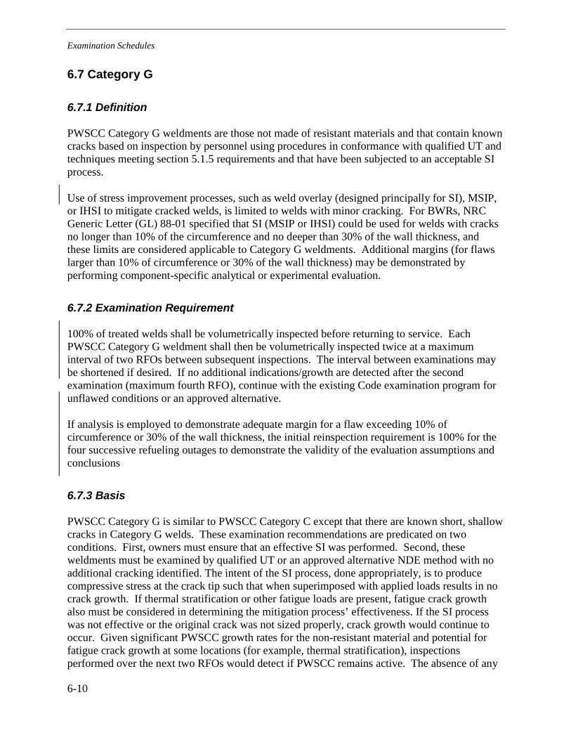
Examination Schedules
6-10
6.7 Category G
6.7.1 Definition
PWSCC Category G weldments are those not made of resistant materials and that contain known cracks based on inspection by personnel using procedures in conformance with qualified UT and techniques meeting section 5.1.5 requirements and that have been subjected to an acceptable SI process.
Use of stress improvement processes, such as weld overlay (designed principally for SI), MSIP, or IHSI to mitigate cracked welds, is limited to welds with minor cracking. For BWRs, NRC Generic Letter (GL) 88-01 specified that SI (MSIP or IHSI) could be used for welds with cracks no longer than 10% of the circumference and no deeper than 30% of the wall thickness, and these limits are considered applicable to Category G weldments. Additional margins (for flaws larger than 10% of circumference or 30% of the wall thickness) may be demonstrated by performing component-specific analytical or experimental evaluation.
6.7.2 Examination Requirement
100% of treated welds shall be volumetrically inspected before returning to service. Each PWSCC Category G weldment shall then be volumetrically inspected twice at a maximum interval of two RFOs between subsequent inspections. The interval between examinations may be shortened if desired. If no additional indications/growth are detected after the second examination (maximum fourth RFO), continue with the existing Code examination program for unflawed conditions or an approved alternative.
If analysis is employed to demonstrate adequate margin for a flaw exceeding 10% of circumference or 30% of the wall thickness, the initial reinspection requirement is 100% for the four successive refueling outages to demonstrate the validity of the evaluation assumptions and conclusions
6.7.3 Basis
PWSCC Category G is similar to PWSCC Category C except that there are known short, shallow cracks in Category G welds. These examination recommendations are predicated on two conditions. First, owners must ensure that an effective SI was performed. Second, these weldments must be examined by qualified UT or an approved alternative NDE method with no additional cracking identified. The intent of the SI process, done appropriately, is to produce compressive stress at the crack tip such that when superimposed with applied loads results in no crack growth. If thermal stratification or other fatigue loads are present, fatigue crack growth also must be considered in determining the mitigation process’ effectiveness. If the SI process was not effective or the original crack was not sized properly, crack growth would continue to occur. Given significant PWSCC growth rates for the non-resistant material and potential for fatigue crack growth at some locations (for example, thermal stratification), inspections performed over the next two RFOs would detect if PWSCC remains active. The absence of any

Examination Schedules
6-11
growth over two cycles (approximately 3-4 years) would indicate the effectiveness of the SI process. If the effectiveness is verified and no other indications are observed, then it is appropriate to continue with the existing ASME Code Section XI examination program for the unflawed condition or approved alternative. The basis for Category C regarding effectiveness of acceptable SI is applicable to Category G weldments.
6.8 Category H
6.8.1 Definition
PWSCC Category H weldments are those that are not made of resistant materials and cannot be volumetrically inspected (for example, examination does not meet requirements of Figure 5-1, Item 6) and are exposed to temperatures equivalent to hot leg or pressurizer temperatures.
6.8.2 Examination Requirement
PWSCC Category H weldments shall be inspected using techniques that meet section 5.1.5 requirements at the frequency defined in Table 6-1 for Category D to the maximum extent possible. The additional requirements of section 5.1.7 also will apply, including documentation of compensatory actions planned. Owners who know that their welds cannot be volumetrically inspected are not required to perform a best-effort NDE; however, by the time the examination is due, they are required to have an approved Deviation in place including a plan to address either the susceptibility of the weld or the inspectability of the weld. Actions identified in this plan will be performed at the earliest possible RFO. A method to detect small leakage <<1 gpm should be considered (for example, a local leak detection system).
6.8.3 Basis
PWSCC Category H welds cannot be effectively inspected for various reasons, such as geometric restriction or accessibility. The hot leg and pressurizer welds are selected for this category due to the temperature dependence of PWSCC demonstrated in test results. These locations are considered to be more susceptible than the cold leg weldments and, thus, require inspection more frequently than cold leg weldments (Category I). Since these locations cannot be volumetrically inspected, a visual examination should be performed to ensure leakage is identified at the earliest possible opportunity (through-wall flaws). It is prudent that actions to resolve the inspectability limitations for these locations include mitigation (either full structural weld overlay or SI or other technically justifiable mitigation actions) to assure the structural integrity of the weld location.

Examination Schedules
6-12
6.9 Category I
6.9.1 Definition
PWSCC Category I weldments are those that are not made of resistant materials and cannot be volumetrically inspected (for example, examination does not meet requirements of Figure 5-1, Item 6) and are exposed to temperatures equivalent to cold leg temperatures.
6.9.2 Examination Requirement
PWSCC Category I weldments shall be inspected using techniques that meet section 5.1.5 requirements at the frequency defined in Table 6-1 for Category E to the maximum extent possible. Additional requirements of section 5.1.7 also will apply, including documentation of compensatory actions planed. Owners who know that their welds cannot be volumetrically inspected are not required to perform a best-effort NDE; however, by the time the examination is due, they are required to have an approved Deviation in place including a plan to address either the susceptibility of the weld or the inspectability of the weld. Actions identified in this plan will be performed at the earliest possible RFO. A method to detect small leakage << 1 gpm should be considered (for example, a local leak detection system).
6.9.3 Basis
PWSCC Category I welds cannot be effectively inspected for various reasons such as geometric restriction or accessibility. Cold leg weldments are selected for this category due to the temperature dependence of PWSCC demonstrated in test results. These locations are considered to be less susceptible than the pressurizer and hot leg weldments and, thus, require inspection less frequently than the pressurizer and hot leg weldments (Category H). Results of Category H inspections can be used to validate or change the Category I examination frequencies, if warranted. Since these locations cannot be volumetrically inspected, visual examination should be performed to ensure leakage is identified at the earliest possible opportunity (through-wall flaws). It is prudent that actions to resolve the inspectability limitations for these locations include mitigation (either full structural weld overlay or SI or other technically justifiable mitigation actions) to assure the structural integrity of the weld location.
6.10 Visual Examinations—Category J
6.10.1 Definition
PWSCC Category J weldments are those that are not made from resistant materials, have not been mitigated, and are exposed to pressurizer or hot leg temperatures. All such non-resistant weldments, regardless of examination status, are included in Category J.

Examination Schedules
6-13
6.10.2 Examination Requirement
In every outage when volumetric examinations are not being performed, PWSCC Category J weldments that are at pressurizer or hot leg temperatures must be visually inspected (bare-metal) until replaced or mitigated.
6.10.3 Basis
Visual examination capable of detecting evidence of leakage (e.g., boric acid deposits) must be performed to supplement UT inspections. Due to the increased likelihood of PWSCC at higher temperatures, weldments operating at higher temperatures shall be inspected more frequently than weldments exposed to cold leg temperatures.
6.11 Visual Examinations—Category K
6.11.1 Definition
PWSCC Category K weldments are those that are not made from resistant materials, have not been mitigated, and are exposed to cold leg temperatures. All such non-resistant weldments, regardless of examination status, are included in Category K. Alternatively, for the reactor vessel (RV) cold leg and other nozzles operating at the nominal cold leg temperature, the utility may use deterministic analysis as a basis to allow these nozzle welds to be visually examined once per interval. This option can only be exercised AFTER welds have been UT examined and fully meet the conditions for being defined as Category E.
6.11.2 Examination Requirement
PWSCC Category K weldments shall be examined visually at least once every three (3) RFOs, not counting RFOs when the weld is examined volumetrically until replaced or mitigated. In RFOs where a UT is performed from the OD, a visual examination is credited. If the UT is performed from the ID, a visual examination may be credited if the 90% examination volume identified in section 5.1.5 was obtained. For weldments in piping that are less than 4” NPS, owners may provide an alternative examination program based on a specific evaluation that includes the consequences and safety assessment of a failure at each Category K weldment.
6.11.3 Basis
Weldments in piping less than 4” NPS and operating at cold leg temperatures are generally (with exceptions) not required by this guideline to be volumetrically examined. Visual bare-metal examination capable of detecting any leakage must be performed in lieu of UT inspections on smaller welds (<4” NPS) and to supplement less frequent volumetric exams for larger welds (≥4” NPS). Cold leg temperature weld locations are considered to be less susceptible than the pressurizer and hot leg weldments and, thus, require inspection less frequently than pressurizer and hot leg weldments (Category J).

Examination Schedules
6-14
Table 6-1 Summary of Volumetric Examination Schedules for PWSCC of PWR Piping Butt Weldments1
PWSCC Category
Description of
Weldments
Inspected? Cracked? (Note 3)
Scope Expansion
(Note 4)
Examination Extent and Schedule (Notes 6 & 9)
A Resistant Materials -- Note 2 Existing Code Examination Program or approved alternative
B Non-resistant Mat.
Reinforced by full structural or optimized weld overlay (Note 8)
Yes
Uncracked (Note 7)
Note 2 Existing Code Examination Program or approved alternative
C Non-Resistant Mat.
Mitigated by SI
Yes
Uncracked (Note 7)
Note 2 50% of each mitigation type within next 6 years; if no indication, continue with existing Code examination program or approved alternative
D Non-resistant Mat.
No SI
Pressurizer and Hot Leg
≥ 2” and MU/HPI
Yes
Uncracked (Note 7)
Note 2 100% per period, but no longer than 5 years between exams for pressurizer locations (include surge line nozzle welds near pressurizer)
100% every 5 years for hot leg locations (include surge line nozzle welds near hot leg and the dual use line MU/HPI nozzle weld)
E Non-resistant Mat.
No SI
Cold Leg
≥ 4” or w/ ECCS function
Yes
Uncracked (Note 7)
Note 2 100 % every 6 years
F Non-resistant Mat.
Cracked
Reinforced by full structural or optimized weld overlay (Note 8)
Yes
Cracked
Note 2 Once in the next 5 years; if no additional indications/growth, continue with existing Code examination program for unflawed condition or approved alternative
G Non-resistant Mat. Cracked
Mitigated by SI
Yes
Cracked
Note 2 100% at 2 RFO intervals. If no additional indications/growth after the 2nd examination (4th RFO), continue with existing Code examination program for unflawed condition or approved alternative (Note 5)

Examination Schedules
6-15
Table 6-1 Summary of Volumetric Examination Schedules for PWSCC of PWR Piping Butt Weldments1 (Continued)
PWSCC Category
Description of
Weldments
Inspected? Cracked? (Note 3)
Scope Expansion
(Note 4)
Examination Extent and Schedule (Notes 6 & 9)
H Non-resistant Mat. Pressurizer and Hot Leg Examination does not meet requirements of Figure 5-1 Item 6 Configuration not addressed in Appendix VIII
No Unknown
Note 2 Frequency defined in Table 6-1 for Category D to the extent possible. Additional requirements as defined in Section 5.1.7.
I Non-resistant Mat. Cold Leg Examination does not meet requirements of Figure 5-1 Item 6 Configuration not addressed in Appendix VIII
No Unknown
Note 2 Frequency defined in Table 6-1 for Category E to the extent possible. Additional requirements as defined in Section 5.1.7.
Table 6-1 Notes: 1. See section 6.1 through 6.9 for detailed examination schedules. Examinations identified in this table refer to ultrasonic
testing. 2. If cracking is detected, the sample size will be expanded to a sample equal in number to the size of the initial sample. If
cracking is detected in the additional sample, all remaining welds in this PWSCC category will be examined. Sample expansion can be limited, with technical justification, to the system or type component (safe end-to-nozzle) in which flaws were detected. However, the sample size should include a number equal to the original sample or otherwise include all welds within the system or component type where expansion is being limited. Scope expansion for Category A joints containing no PWSCC-susceptible materials shall be governed by the applicable ASME Code requirements. Otherwise, the population for Category A sample expansion may be limited to joints of similar materials and configuration.
3. These questions apply for determining the examination schedule and relate to the status before the examination is performed.
4. Criteria for expansion are applicable to the current examination and outage. 5. If analysis is employed to demonstrate adequate margin for a flaw exceeding 10% of circumference and / or 30% of wall
thickness, the initial reinspection requirement is 100% for the four successive refueling outages to demonstrate the validity of the evaluation assumptions and conclusions.
6. Approved alternative refers to an inspection program alternative approved by the NRC with consideration of the implications for MRP-139 implementation.
7. An unmitigated joint may only be designated “Uncracked” based on inspection results meeting all applicable coverage and qualification requirements of the ID-connected inspection volume defined in Section 5 and otherwise a flaw must be assumed and the joint is conservatively designated “Cracked”. See further discussion in Section 6.0, “Prior Inspection Results”.
8. To be assigned to these categories, optimized weld overlays must be designed and fabricated in accordance with specific requirements defined in MRP-169, Section 4 [36], including design basis flaw size, residual and crack growth analyses, and expanded post-overlay exam volume.
9. To accommodate normal variations in nominal fuel cycle duration and outage scheduling when the inspection interval is designated in years, the specified re-inspection intervals may be extended by a maximum of 120 days. Alternatively, for nominal 18 month fuel cycles, 5 and 6 year intervals may be considered as three and four RFOs respectively and for a nominal 24-month fuel cycle, two and three RFOs respectively.

Examination Schedules
6-16
Table 6-2 Summary of Visual Examination Schedules for PWSCC of PWR Piping Butt Weldments
PWSCC Category
Description of Weldments Examination Extent and Schedule
J Non-resistant Mat
Pressurizer and Hot Leg
In the outages when volumetric examinations are not being performed, visual examination every RFO as defined in section 5.2.1 or until mitigated or replaced
K Non-resistant Mat
Cold Leg
Visual examination as defined in section 5.2.1at least once every three (3) RFOs (not counting RFOs when weld is examined volumetrically as one of the three) or until mitigated or replaced. Alternatively, for the RV cold leg and other nozzles at nominal cold leg temperature, use deterministic analysis as a basis to allow these nozzle welds to be visually examined once per 10-year ISI interval. This option can only be exercised AFTER welds have been UT-examined and fully meet the conditions for being defined as Category E.
In RFOs where a UT is performed from the OD, a visual examination is credited. If the UT is performed from the ID, a visual examination may be credited if the 90% examination volume identified in section 5.1.5 was obtained.

7-1
7 EVALUATION METHODOLOGIES
This section summarizes evaluation methodologies that are considered applicable for the primary system piping butt weld locations. These methods can be applied to Alloy 600, 82, and 182 material at the subject welds since they are not considered PWSCC-resistant. For these materials, limit load analysis methods are applicable. This methodology can be used for various purposes including
• disposition of uninspectable areas and missed coverage for circumferential flaws (Sections 5.1.6 & 5.1.7)
• disposition of indications found during inspections (surface-connected or embedded flaws), • determination of effectiveness of stress improvement processes, and • determination of weld overlay (full structural or stress improvement) design.
ASME Code Section XI contains methodology for performing disposition of flaws using limit load and elastic-plastic (i.e., EPFM) analysis methods in IWB-3600 and Nonmandatory Appendix C. For Ni-Cr-Fe non-flux welds such as Alloy 82, limit load is applicable due to the significant ductility and toughness of the material. However, an EPFM analysis may be more broadly accepted because of the combination of different materials in a typical dissimilar metal weld joint and the lack of experimental confirmation of limit load predictions for dissimilar metal weld joints. For Ni-Cr-Fe flux welds such as Alloy 182, the 2007 edition of Section XI, Nonmandatory Appendix C recommends use of C-6000 EPFM analyses rather than limit load given that Appendix C assumes the fluence at the locations of interest may be sufficient to cause significant reduction in ductility.1
Any indications that are found during inspections must be evaluated per ASME Code Section XI requirements. Indications that do not satisfy acceptance criteria of IWB-3500 must be dispositioned by analysis, repaired, or replaced. Per IWB-3500 of the ASME Code, indications must be evaluated to determine if they must be analyzed as surface-connected or can be considered embedded. Embedded flaws are considered isolated from the PWSCC environment and only subject to fatigue crack growth. Embedded flaws also must be evaluated to assure that cyclic loading does not result in the indication breaking the remaining ligament and, as a result, be subjected to the primary water environment. Surface-connected flaws would be subject to
Other technically justifiable procedures such as pipe burst theory also may be used.
1 Note that the 2007 edition of Section XI, Nonmandatory Appendix C, Paragraph C-6330 does not include Z factor load multipliers appropriate for Ni-Cr-Fe flux welds. Hence, the treatment of Ni-Cr-Fe flux welds within the 2007 edition of Section XI, Appendix C is incomplete. Conservative Z factor load multipliers appropriate for Ni-Cr-Fe Alloy 82 and 182 welds for the EPFM evaluation can be found in Reference 44.

Evaluation Methodologies
7-2
potential PWSCC. Any flaw attributed to PWSCC, regardless of depth, will be evaluated even if it meets IWB-3500 requirements.
7.1 Indication Disposition
In cases where indications cannot be dispositioned by ASME Code Section XI IWB-3500 acceptance standards, flaw evaluations similar to ASME Code Section XI IWB-3600 procedures can be performed. The disposition of indications requires the following steps be performed:
• Determination of allowable flaw size – Axial or circumferential
• Crack growth calculation – PWSCC and fatigue
• Comparison of predicted flaw size with allowable end-of-period flaw size
7.1.1 Allowable Flaw Size
To determine the allowable flaw size at a weld location, appropriate applied loads must be used in evaluating the stress condition at the butt weld location of interest. Using ASME Code Section XI methodology for the allowable flaw size evaluation, the limiting load conditions must be considered consistent with the plant design basis. For non-flux welds (for example, GTAW and GMAW), these loads typically include those due to pressure, deadweight, seismic, and other primary loads. For flux welds—for example, submerged arc welds (SAW), shielded-metal arc welds (SMAW), and flux-cored arc welding (FCAW)—the applied loads must include secondary thermal loads. However, because an EPFM analysis may be more broadly accepted for non-flux weld material within dissimilar metal weld joints, secondary thermal loads may also be included in the applied loads for the case of Alloy 82 non-flux welds.
The allowable flaw sizes evaluation must include all loading conditions—normal or upset, or emergency or faulted—since these load conditions require different safety factors.
If multiple flaws are to be considered based on either inspection results or inspection coverage limitations, the flaw combination rules within ASME B&PV Code, Section XI, IWA-3330 (2003 Addenda or later) should be applied.
Allowable flaw size evaluations can be performed for both axial and circumferential flaws. Note that the ASME Code in Section XI, Appendix C, does not permit any flaw to be deeper than 75% of the actual local pipe thickness.
7.1.2 Crack Growth Calculation
Crack growth calculations must be performed for the operating period of interest. Applicable loads are those present during sustained normal operation. These loads typically include those due to thermal stress, pressure, deadweight, and weld residual stress. Appropriate weld residual

Evaluation Methodologies
7-3
stress, (e.g., with due consideration of pipe thickness and diameter), must be considered in the crack growth calculation. The appropriate loads must be considered for the particular flaw orientation, axial or circumferential.
It is important to note that unless owners can definitively show that no repairs are present, a weld repair must be assumed at the location of interest. To date, cracking in non-resistant PWSCC material has been located in suspected repair areas. Thus, the residual stress distribution used in the crack growth calculation must be for a repaired configuration. If it can be demonstrated that there has been no weld repair at the location of interest, weld residual stress applicable for the as-welded fabrication weld may be used.
PWSCC crack growth rates (see section 2.6.2) must be used in crack growth rate calculations. These crack growth rates are a function of temperature as well as the applied stress. It should be noted that these crack growth rates are significant and, in many cases, will limit the ability to demonstrate continued operation with the flaw left as is.
In accordance with ASME B&PV Code, Section XI, IWA-3330 (2003 Addenda or later) combination of multiple planar flaws is not required for fatigue or SCC crack growth analyses.
Cyclic loading also must be considered, and a fatigue crack growth calculation must be performed if thermal stresses are sufficient to cause crack growth. Fatigue crack growth must be added to PWSCC growth to obtain the end-of-operating period flaw size. Cyclic loading also must be considered as appropriate given plant-specific conditions at the location of interest. The supporting analyses to this guideline identified thermal fatigue as a particularly relevant crack propagation mechanism. In that context, a fatigue crack growth calculation must be performed if thermal stresses are sufficient to cause crack growth. In general, crack growth from all relevant causes must be added to PWSCC growth to obtain the end-of-operating period flaw size.
7.1.3 Determination of Flaw Acceptance
The end-of-operating period flaw size must be compared against the allowable flaw size to determine if the flaw is acceptable by demonstrating that the required safety factors are met through the entire operating period. If the safety factors are not met, the operating period may be reduced to accommodate an earlier examination to ensure that structural safety margins are maintained throughout the operating period. Alternatively, the weld will need to be repaired.
In cases of missed coverage and uninspectable areas for circumferential flaws (Sections 5.1.6 & 5.1.7), a flaw equal in circumferential extent to the that of the missed coverage or uninspectable area must be postulated and assumed to be through wall unless an alternative flaw depth assumption can be technically justified (e.g., aspect ratio for through-thickness flaw is unrealistic). As this condition is hypothetical, the depth limitation to less than 75% of the actual local pipe thickness does not apply (section 7.1.1).
7.1.4 Stress Improvement Effectiveness
As mentioned in section 3.0, an SI is acceptable if it produces a significant change in the weld residual stress such that the stress is compressive when combined with other sustained operating

Evaluation Methodologies
7-4
loads for a preemptive SI. For an SI on a cracked weld, the SI is acceptable if the stress intensity factor at the crack tip is negative when all loads are considered. Stresses that must be included for determining SI effectiveness are stresses present during normal operation. Note that fatigue loading also must be considered, for example, fatigue loading due to thermal stratification. The appropriate SI residual stress must be included.
7.1.5 Weld Overlay Design
The design of the weld overlay depends on the type of overlay being considered. A full structural weld overlay is designed assuming no credit for the original pipe wall. ASME Code Case N-504-2 and N-740-1 [21] can be used for guidance in the design of the weld overlay. The Code Cases provide guidance for the thickness and length of the full structural weld overlay. Guidance for the design of optimized weld overlays is contained in Section 4 of MRP-169 [36].
As noted earlier, many weld overlays have been applied to BWR piping. U.S. Nuclear Regulatory Commission (USNRC) Generic Letter 88-01 [22] and NUREG 0313 Rev. 2 [23] provide the requirements/acceptance for weld overlays. The design of overlays must satisfy the safety factors of ASME Code Section XI.
Code Case N-638 also may need to be used if welding is required on nozzle material. Code Case N-638 allows for ambient temperature temper bead welding. Currently, Code Case N-638 limits the amount of temper bead welding on nozzle material to 100 in2. If the limit of 100 in2 is to be exceeded, a relief request must be submitted to USNRC. At this time, a Code Case is being developed to increase the 100 in2 limit.

8-1
8 SUMMARY
This guideline has been prepared to meet the objectives and requirements of the NEI materials initiative [34]. It provides requirements classified as “mandatory” for inspecting Alloy 82/182 butt welds in PWR plants. Table 8-1 provides a summary of the required actions contained in this guideline.
8.1 Table 8-1 Required Actions Summary
Section Requirements Implementation Category
1.2 Each owner is required to implement this guideline and perform the first inspections consistent with the schedule outlined in this section.
Mandatory
5
(includes subsections)
This section provides the process for determining what NDE method should be used for each DM weld and if any additional analysis is necessary based on NDE method chosen.
Mandatory
6
(includes subsections)
This section provides the process for determining what re-examination frequency is required for each DM weld.
Mandatory


9-1
9 REFERENCES
1. Alloy 82/182 Pipe Butt Weld Safety Assessment for US PWR Plant Designs: Westinghouse and CE Plant Designs (MRP-109), EPRI, Palo Alto, CA: 1009804.
2. Alloy 82/182 Pipe Butt Weld Safety Assessment for US PWR Plant Designs: Babcock & Wilcox Design Plants (MPR-112), EPRI, Palo Alto, CA: 1009805.
3. D. J. Seman, et al., “Primary Water Stress Corrosion Cracking of Alloy 600—Effects of Processing Parameters,” Proceedings: 1991 EPRI Workshop on PWSCC of Alloy 600 in PWRs, Appendix E3, EPRI, Palo Alto, CA: 1992. TR-100852.
4. J. V. Mullen and R. J. Parrington, “Stress Corrosion of Alloy 600 Weld Metal in Primary Water,” Proceedings: 1992 EPRI Workshop on PWSCC of Alloy 600 in PWRs, Appendix F3, EPRI, Palo Alto, CA: 1993. TR-103345.
5. D. Buisine, et al., “PWSCC of Nickel Based Weld Metals with Various Chromium Contents,” Proceedings: 1994 EPRI Workshop on PWSCC of Alloy 600 in PWRs, Appendix D5, EPRI, Palo Alto, CA:1995. TR-105406.
6. Pressurized Water Reactor Primary Water Chemistry Guidelines, Volume 1, Revision 5, EPRI, Palo Alto, CA: September 2003 (Revised October 2003). 1002884.
7. Crack Growth of Alloy 182 Weld Metal in PWR Environments (MRP-21), EPRI, Palo Alto, CA: 2000. 1000037.
8. Materials Reliability Program (MRP) Crack Growth Rates for Evaluating Primary Water Stress Corrosion Cracking (PWSCC) of Thick-Wall Alloy 600 Materials (MRP-55) Revision 1, EPRI, Palo Alto, CA: 2002. 1006695
9. Materials Reliability Program—Welding Residual and Operating Stresses in PWR Plant Alloy 182 Butt Welds (MRP-106), EPRI, Palo Alto, CA, 1009378.
10. Materials Reliability Program: GE Experience Report on Cracking in Alloy 182 (MRP-57): BWR Alloy 182 Stress Corrosion Cracking, EPRI, Palo Alto, CA: 2001. 1006603.
11. Materials Handbook for Nuclear Plant Pressure Boundary Applications, EPRI, Palo Alto, CA: 2002. 1002792.
12. Recommendation for Inspection of Alloy 600/82/182 Pressure Boundary Components, letter from Leslie Hartz to all PWR plants, January 20, 2004 (MRP 2003-039).
13. USNRC, Stress Corrosion Cracking in Thick-Wall Large-Diameter, Stainless Steel, Recirculation System Piping at BWR Plants, IE Bulletin 82-03, October 14, 1982.
14. L. Becker, “Performance Demonstration—25 Year of Progress,” Proceedings of the Third International Conference on NDE in Relation to Structural Integrity for Nuclear and Pressurized Components, 14-16 November, 2001. Seville, Spain.

References
9-2
15. Letter R. DeYoung, USNRC to G. Neils, BWROG, Coordination Plan for NRC/EPRI/BWROG Training and Qualification Activities of NDE Personnel, August 24, 1984.
16. USNRC, Ultrasonic Inspection Techniques for Dissimilar Metal Welds, Information Notice 90-3, May 1, 1990.
17. Examination of Dissimilar Metal Welds in BWR and PWR Piping Systems, EPRI, Palo Alto, CA.: 1993. TR-102148.
18. Dissimilar Metal Weld Examination—Guidance and Technical Basis for Qualification, EPRI, Palo Alto, CA: 2003. 1008007.
19. Technical Justification for the Extension of the Interval between Inspection of Weld Overlay Repairs, EPRI, Charlotte, NC, February 1999: TR-110172.
20. Material Reliability Program: Alloy 82/182 Pipe Butt Weld Safety Assessment for US PWR Plant Designs (MRP-113), EPRI, Palo Alto, CA: August, 2004,1009549 .
21. ASME Code Case N-504-2, Alternative Rules for Repair of Classes 1, 2, and 3 Austenitic Stainless Steel Piping.
22. USNRC, Generic Letter 88-01, NRC Position on IGSCC in BWR Austenitic Stainless Steel Piping, United State, January 1988.
23. USNRC, Technical Report on Material Selection and Processing Guidelines for BWR Coolant Pressure Boundary Piping, NUREG-0313, Rev. 2, January 1988.
24. Material Reliability Program, Evaluation of the Effect of Weld Repairs on Dissimilar Metal Butt Welds (MRP-114), EPRI, Palo Alto, CA: 2004. 1009559..
25. Needed Action for Visual Inspection of Alloy 82/182 Butt Welds and Good Practice Recommendations for Weld Joint Configurations, letter from Leslie Hartz to all PWR Owners, April 2, 2004 (MRP 2004-05).
26. P. L. Andresen, “Effects of Zinc Additions on the Crack Growth Rate of Sensitized Stainless Steel and Alloys 600 and 182 in 288°C Water,” paper 72 presented at Water Chemistry of Nuclear Reactor Systems 6, BNES, London 1992.
27. Materials Reliability Program: Crack Growth Rates for Evaluating Primary Water Stress Corrosion Cracking (PWSCC) of Alloy 82, 182, and 132 Welds (MRP-115), EPRI, Palo Alto, CA: 2004. 1006696.
28. P. L. Andresen and T. M. Angeliu, “Effects of Zinc Additions on the Stress Corrosion Crack Growth Rate of Sensitized Stainless Steel, Alloy 600 and Alloy 182 Weld Metal in 288°C Water,” paper 409 presented at Corrosion 95, NACE, Orlando, FL, March 22, 1995.
29. P.M. Scott, “Stress Corrosion Cracking in Pressurized Water Reactors—Interpretation, Modeling and Remedies,” Corrosion, Vol.56, No.8, August 2000, pp. 771-782.
30. Materials Reliability Program: Mechanical Stress Improvement Process (MSIP™) Implementation and Performance Experience for PWR Applications (MRP-121), EPRI, Palo Alto, CA 2004. 1009503.

References
9-3
31. Material Reliability Program—PWSCC of Alloy 600 Type Materials in Non-Steam Generator Tubing Application—Survey Report Through June 2002. Part 1: PWSCC in Components other than CRDM/CEDM Penetrations (MRP-87), EPRI, Palo Alto, CA 2003, 1007832.
32. G.J. Powel, S.S. Porembka, and J.R. Politano, “Destructive Examination of an Alloy 600 Pressurizer Relief Line Elbow Removed from an Advanced Test Reactor Test Loop,” Proceedings: 1992 EPRI Workshop on PWSCC of Alloy 600 in PWRs, EPRI, Palo Alto, CA. 1993. TR-103345.
33. BWR Vessel and Internals Project: Technical Basis for Revisions to Generic Letter 88-01 Inspection Schedules (BWRVIP-75), EPRI, Palo Alto, CA and BWRVIP: 1999, TR-113932.
34. Guidance for Management of Materials Issues, Nuclear Energy Institute, Washington, DC: Revision 1, April 2007. NEI 03-08, and NEI Materials Guidelines Implementation Protocol, Revision 3, July 2008.
35. ASME Code Case N-740-1, Alternative Rules for Repair of Classes 1, 2, and 3 Austenitic Stainless Steel Piping.
36. Materials Reliability Program (MRP-169), Technical Basis for Preemptive Weld Overlays for Alloy 82/182 Butt Welds in PWRs, 1016602, Revision 1, June 2008
37. MRP-139 Interim Guidance, letter from M. Robinson, Duke Energy to MRP Technical Advisory Group, August 2006, (MRP 2006-018).
38. MRP-139 Interim Guidance on <4” Volumetric Exam Requirements, letter Denny Weakland, First Energy to MRP Technical Advisory Group, November 2007 (MRP 2007-038).
39. MRP-139 Interim Guidance on Bare Metal Visual Exam Requirements, letter Denny Weakland, First Energy to MRP Technical Advisory Group, November 2007 (MRP 2007-039).
40. MRP-139 Interim Guidance on Cast Austenitic Stainless steel Exam Requirements, letter J. Hagan, First Energy to MRP Technical Advisory Group, May 2008, (MRP 2008-033).
41. WCAP-16423-NP – Pressurized Water Reactor Owners Group Standard Process and Methods for Calculating RCS Leak Rate for Pressurized Water Reactors, Revision 0, September 2006.
42. WCAP-16465-NP – Pressurized Water Reactor Owners Group Standard RCS Leakage Action Levels and Response Guidelines for Pressurized Water Reactors, Revision 0, September 2006.
43. OG-07-387 – PWR Owners Group Recommendations for Implementation of Guidelines for PWROG RCS Leak Rate Programs with Respect to NEI-03-08 (PA-OSC-0189 and PA-OSC-0218), letter F. Schiffley, PWROG Chairman to PWROG Executive Committee, August 27, 2007.
44. W. Bamford, R. Cipolla, D. Rudland, & G. DeBoo, “PVP2008-61840, Technical Basis For Revisions To Section Xi Appendix C For Alloy 600/82/182/132 Flaw Evaluation In Both PWR and BWR Environments”, Proceedings of 2008 ASME Pressure Vessel and Piping Division Conference, Chicago, Il; July 28-31, 2008
45. MRP-139 Rev 01 Update Information, letter B Grambau, AREVA to C. Harrington, EPRI MRP, November 18, 2008, AREVA-08-03980 (MRP 2008-067)


A-1
A DM WELD MEASUREMENT TEMPLATE
ISI INSTRUCTIONS FOR DM WELD INFORMATION Items 1-12 should be performed during walk down. Items 13-20 provide information on assessing future examination requirements based on walkdown results.
1. Take pictures of general area for obstructions. If obstructions such as hangers or whip restraints, adjacent valves or components are present, determine the maximum vertical clearance and the surface distance available to mount scanners.
2. Take pictures of DM weld with 6” scale.
3. Take OD weld profile contour at zero degrees using pen gauges or other contouring devices.
4. Take UT thickness at zero degrees. Additional weld contours and thickness may be taken at 90, 180, or 270 degrees if configuration is not uniform around the circumference.
5. Identify weld toes/coolant system (CS)/SS interface.
6. If weld toes are not readily visible, acid etching or eddy current surface probe may be used to identify Alloy 82/182-to-SS interface.
7. Take contour measurements using attached example as a guideline.
8. Take circumference measurements on parallel surfaces for each diameter (nozzle, safe-end, elbow).
9. Provide comments (for example, weld crown conditions). The weld crown and scan surface must allow unimpeded access across the weld and butter. Waviness, tapers, exposed weld toes that cause the search unit to lift off the surface must be addressed. The general surface condition should either be machined or ground smooth to a 250-RMS (root mean square) finish, approximately. Long-range waviness can be measured by placing the required search units on the examination surface to assure that there are no gaps between the surface and the bottom of the probe greater than approximately 1/32” over the entire scanning surface.
10. Document any areas that show evidence of weld repairs.

DM Weld Measurement Template
A-2
11. If possible, obtain dose rates in the area of the weld and on contact or, at a minimum, review dose rates from previous outages.
12. Previous inspection data should be reviewed to determine what coverage was actually obtained, if any indications were reported, and what limitations may be present. These data also will help determine how adequate the previous inspection may have been.
13. Fabrication data should be reviewed to determine the location and type of any weld repairs. This fabrication data review also should include review of any radiographs. Digitization of construction radiographs may be useful especially if weld repairs have been performed or previous UT examinations showed indications.
14. Design and as-built data should be reviewed and compared to the as-found conditions. Using all of this data, the actual configuration can be reconstructed.
15. Using the reconstruction, examiners should compare the configuration to samples included in the PDI test set and review the applicable procedure and the PDI site-specific mock-up criteria. This evaluation must be performed at a minimum of one outage before the required inspection to allow time for fabrication of mock-ups and qualification of the procedures and personnel.
16. If the as-found configuration is determined to be outside the qualified procedure, then a feasibility evaluation should be performed to determine if meaningful ultrasonic examinations could be performed. If it is determined that meaningful UT cannot be performed, alternative or supplemental examinations should be considered.
17. If the weld is covered by the qualification or has an equivalent procedure, a scan plan should be developed based on the actual coverage obtainable. This scan plan should include the selection of optimum search units based on criteria included in the applicable procedure. A plot should be developed to show areas of coverage in both the axial and circumferential directions.
18. Owners should check the available search unit instrument combination to determine if the required equipment has been qualified.
19. If the weld is covered by the qualification, but the desired equipment is not on PDI Table 1, it should be sent to the NDE Center for qualification. Vendor, owner, or PDA personnel can perform this demonstration.
20. If a site-specific mock-up is required, it must be fabricated and the required demonstrations performed in accordance with the PDI site-specific mock-up criteria.

DM Weld Measurement Template
A-3

DM Weld Measurement Template
A-4

DM Weld Measurement Template
A-5


B-1
B DM WELD MOCKUP CRITERIA 5/28/04

DM Weld Mockup Criteria 5/28/04
B-2

DM Weld Mockup Criteria 5/28/04
B-3
DM Weld Mockup Criteria 5/28/04
B-4

DM Weld Mockup Criteria 5/28/04
B-5

DM Weld Mockup Criteria 5/28/04
B-6

DM Weld Mockup Criteria 5/28/04
B-7

DM Weld Mockup Criteria 5/28/04
B-8

DM Weld Mockup Criteria 5/28/04
B-9

DM Weld Mockup Criteria 5/28/04
B-10

C-1
C RECORD OF REVISION

Record of Revision
C-2
MRP-139, Rev. 1 Record of Revision
~Page # Change Bases i & ii • Title & Disclaimer Pages: Administrative changes iii • Citations: Admin and to reflect major contributors iv • Report Summary: Revised to reflect recent OE (Wolf Creek, etc.) v • Administrative – describe intent & scope of R1 and list issued interim
guidance incorporated into R1. vii • New section on recent exam results ix • Correction – R0 omitted the title for section 8 – “Summary” and mixed
sections 8 & 9. Also, Appendix C has been deleted and the contents are reflected in section 7.
1-1 • Administrative & editorial 1-2 • Administrative & editorial
• Inquiry MRP139-11, #1 • Reinforced requirements for ASME Code compliance are unchanged
1-3 and 1-4
• NRC Comment 1 – future adjustments w/ example • NRC Comment #2 – deleted LBB statements • NRC Comment #3, Inquiry MRP139-09 & Interim Guidance MRP 2006-018; • NRC Comment #5 – Visual exam transition requirements from MRP-139
transmittal letter • NRC Comment 6 (Should vs. shall) • NRC Comment #25 – RI-ISI from transmittal letter • Interim Guidance MRP 2006-018 – Schedule Deviation • Interim Guidance MRP 2007-038 - <4” Volumetric • Interim Guidance MRP 2007-039 - <4” Visual Exam – “start the clock” date
(Inquiry MRP139-13 initiated this interim guidance) • Inquiry MRP139-03 “A” – basis for B&W special cases • Inquiry MRP139-04 – clarify applicable size ranges • Reflect revised intent for Section 5.1.7 (deviation) • General editorial for clarification
1-5 • Editorial • Inquiry MRP139-19 – Inspection Interval Definition & Latitude
2-1 • Inquiry MRP139-10 – Joint Design • Editorial
2-2 • Inquiry MRP139-05 – Typical, other locations could exist • Editorial
2-3 • Inquiry MRP139-07 - Other examples of A600 safe-ends 2-8 • Editorial to reflect certain statements were accurate at the time Rev. 0 was
issued and have not been updated in order to maintain a consistent context for that section of the report.

Record of Revision
C-3
MRP-139, Rev. 1 Record of Revision
~Page # Change Bases 2-10 • Clarify why listed items are not included the table • Resolved inconsistency between text in section 2.4 and Fig. 2-3 regarding core
flood nozzle operating temperature, updated design hot leg temp, and updated RV Head information
3-1 • Clarify technical basis for overlays (not just FSWOL) being a SI method 3-2 • Editorial – Inspection doesn’t make SI “effective”
• Generalize weld overlay consistent with treatment of full structural and OWOL in later sections
3-3 • Editorial – Inspection doesn’t make SI “effective” • Reflect categorization for OWOL (plant implementation can’t proceed w/o
MRP-169 SER) 4-2 • Editorial – added comma 4-5 • Added section and minor edits to address recent inspection experience (Wolf
Creek, etc.) 5-1 • General editorial for clarification
• NRC Comment #18 – Clarify applicability of ASME Requirements 5-2 • General editorial for clarification
• Revised & reformatted inspection volume material to clarify determination of required inspection volume and role of Fig. 5-2
• Rewording to clarify intent of original sentence that implied that the full thickness of the weld must be interrogated – reflects PDI positions not extra MRP-139 requirements
• Inquiry MRP139-18 – Wetted surface coverage requirement • Inquiry MRP139-16 – CASS – Interim Guidance MRP 2008-033 • Inquiry MRP139-14 – Clarify intent for wetted ID susceptible material • Interim Guidance MRP 2008-033 – DM weld joints to CASS
5-3 • Editorial – Nozzle to safe-end weld is generally shop not field 5-4 • General editorial for clarification
• NRC Comment #17 – Sounded like required less than ASME so improved words
• NRC Comment #12 – Refer to App. VIII Supplements 10 & 11 5-5 • General editorial for clarification 5-6 • General editorial for clarification of intent (should be no change of intent)
• Reflect revised intent of Section 5.1.7 (deviation) 5-7 • Additional guidance provided in 5.1.6 to address treatment of installed
obstructions to acceptable exam coverage (e.g., branch line immediately adjacent to DM weld or safe end) in cold leg lines
5-8 • Complete rewrite of 5.1.7 – similar to original intent but reflects significant changes – now directs utility to prepare a deviation and suggests compensatory measures

Record of Revision
C-4
MRP-139, Rev. 1 Record of Revision
~Page # Change Bases • NRC Comment #7 – approved mitigation methods • NRC Comment #10 – NRC-approved Relief Requests • NRC Comment #11 – Scope includes cold leg and above • Inquiry MRP139-09 – Earliest Possible RFO clarification
5-9 • Completion of changes on pages 5-7 and 5-8 5-10 • Replaced Figure 5-1 w/ minor editorial changes to better match text
• NRC Comment #9 – Box 7 incorrectly includes “See Note 1” 5-11 • Added reference to inspection volume discussion on 5-2 and words to clarify
intent of exam surface designation on joint OD 6-1 • General editorial for clarification
• LBB Report (Ref 21) was deleted before Rev. 0 was issued • Should to shall in reference to 5.1.7 Alternative Methods (and 5.1.6) • Added new text to clarify the scope of the document as well as how welds are
categorized in Section 6 6-2 • Added new text to clarify the scope of the document as well as how welds are
categorized in Section 6 • NRC Comment #11 – Cold leg temperature and above • Inquiry MRP139-01 – Joint Nominal Size • Inquiry MRP139-07 – Joint Design - Scope • Inquiry MRP139-10 – Joint Design • Inquiry MRP139-11 – Materials of Construction • Inquiry MRP139-15 – Nominal Operating Temperature at the Joint Location • Inquiry MRP139-17 – > 4" NPS, <Cold Leg Temp, w/ ECCS Function
6-3 • Added new text to clarify the scope of the document as well as how welds are categorized in Section 6
• Inquiry MRP139-06 – Clarify “no known cracks” can’t be assumed, must be shown through inspection
• Inquiry MRP139-11 – Prior Inspection Results 6-4 • Inquiry MRP139-08 – MRP-139 visuals don’t apply to Cat A
• Text added to address OWOLs (plant implementation can’t proceed w/o MRP-169 SER)
6-5 • NRC Comment #19 – NDE for New mitigation methods – 6.3.1 – revised to clarify intent
• Text added to address OWOLs (plant implementation can’t proceed w/o MRP-169 SER)
6-7 • Interim Guidance MRP 2007-038 - <4” Volumetric • Revised 6.4.3 temperature given as cold leg / hot leg boundary to be consistent
with section 5.1.7. 6-8 • Interim Guidance MRP 2007-038 - <4” Volumetric in 6.5.1 6-9 • Text added in 6.6 to address OWOLs (plant implementation can’t proceed w/o
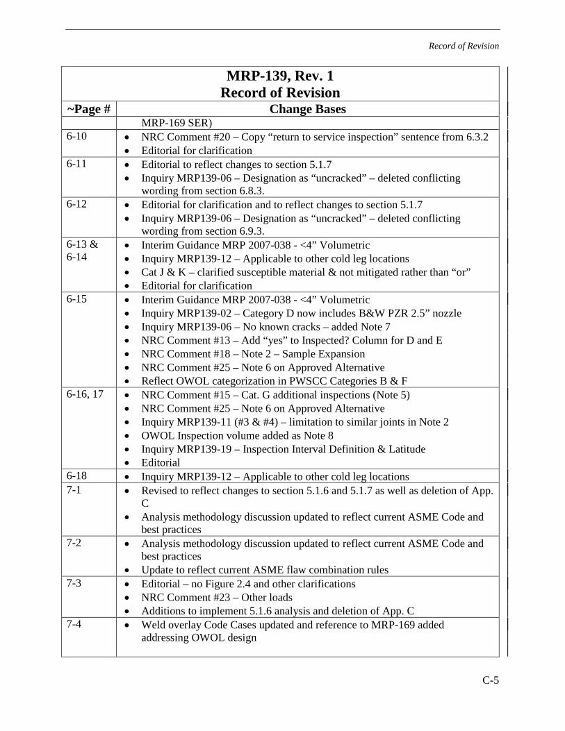
Record of Revision
C-5
MRP-139, Rev. 1 Record of Revision
~Page # Change Bases MRP-169 SER)
6-10 • NRC Comment #20 – Copy “return to service inspection” sentence from 6.3.2 • Editorial for clarification
6-11 • Editorial to reflect changes to section 5.1.7 • Inquiry MRP139-06 – Designation as “uncracked” – deleted conflicting
wording from section 6.8.3. 6-12 • Editorial for clarification and to reflect changes to section 5.1.7
• Inquiry MRP139-06 – Designation as “uncracked” – deleted conflicting wording from section 6.9.3.
6-13 & 6-14
• Interim Guidance MRP 2007-038 - <4” Volumetric • Inquiry MRP139-12 – Applicable to other cold leg locations • Cat J & K – clarified susceptible material & not mitigated rather than “or” • Editorial for clarification
6-15 • Interim Guidance MRP 2007-038 - <4” Volumetric • Inquiry MRP139-02 – Category D now includes B&W PZR 2.5” nozzle • Inquiry MRP139-06 – No known cracks – added Note 7 • NRC Comment #13 – Add “yes” to Inspected? Column for D and E • NRC Comment #18 – Note 2 – Sample Expansion • NRC Comment #25 – Note 6 on Approved Alternative • Reflect OWOL categorization in PWSCC Categories B & F
6-16, 17 • NRC Comment #15 – Cat. G additional inspections (Note 5) • NRC Comment #25 – Note 6 on Approved Alternative • Inquiry MRP139-11 (#3 & #4) – limitation to similar joints in Note 2 • OWOL Inspection volume added as Note 8 • Inquiry MRP139-19 – Inspection Interval Definition & Latitude • Editorial
6-18 • Inquiry MRP139-12 – Applicable to other cold leg locations 7-1 • Revised to reflect changes to section 5.1.6 and 5.1.7 as well as deletion of App.
C • Analysis methodology discussion updated to reflect current ASME Code and
best practices 7-2 • Analysis methodology discussion updated to reflect current ASME Code and
best practices • Update to reflect current ASME flaw combination rules
7-3 • Editorial – no Figure 2.4 and other clarifications • NRC Comment #23 – Other loads • Additions to implement 5.1.6 analysis and deletion of App. C
7-4 • Weld overlay Code Cases updated and reference to MRP-169 added addressing OWOL design

Record of Revision
C-6
MRP-139, Rev. 1 Record of Revision
~Page # Change Bases 9-3 & 9-4 • Added references C-1 • Deleted (Section 7 covers necessary information)


Electric Power Research Institute3420 Hillview Avenue, Palo Alto, California 94304-1338 • PO Box 10412, Palo Alto, California 94303-0813 USA
800.313.3774 • 650.855.2121 • [email protected] • www.epri.com
The Electric Power Research Institute (EPRI), with major
locations in Palo Alto, California; Charlotte, North Carolina; and
Knoxville, Tennessee, was established in 1973 as an independent,
nonprofit center for public interest energy and environmental
research. EPRI brings together members, participants, the Institute’s
scientists and engineers, and other leading experts to work
collaboratively on solutions to the challenges of electric power. These
solutions span nearly every area of electricity generation, delivery,
and use, including health, safety, and environment. EPRI’s members
represent over 90% of the electricity generated in the United States.
International participation represents nearly 15% of EPRI’s total
research, development, and demonstration program.
Together...Shaping the Future of Electricity
Export Control Restrictions
Access to and use of EPRI Intellectual Property is granted with the
specifi c understanding and requirement that responsibility for ensur-
ing full compliance with all applicable U.S. and foreign export laws
and regulations is being undertaken by you and your company. This
includes an obligation to ensure that any individual receiving access
hereunder who is not a U.S. citizen or permanent U.S. resident is
permitted access under applicable U.S. and foreign export laws and
regulations. In the event you are uncertain whether you or your com-
pany may lawfully obtain access to this EPRI Intellectual Property, you
acknowledge that it is your obligation to consult with your company’s
legal counsel to determine whether this access is lawful. Although
EPRI may make available on a case-by-case basis an informal as-
sessment of the applicable U.S. export classifi cation for specifi c EPRI
Intellectual Property, you and your company acknowledge that this
assessment is solely for informational purposes and not for reliance
purposes. You and your company acknowledge that it is still the ob-
ligation of you and your company to make your own assessment
of the applicable U.S. export classifi cation and ensure compliance
accordingly. You and your company understand and acknowledge
your obligations to make a prompt report to EPRI and the appropriate
authorities regarding any access to or use of EPRI Intellectual Prop-
erty hereunder that may be in violation of applicable U.S. or foreign
export laws or regulations.
© 2008 Electric Power Research Institute (EPRI), Inc. All rights reserved. Electric Power Research Institute, EPRI, and TOGETHER...SHAPING THE FUTURE OF ELECTRICITY are registered service marks of the Electric Power Research Institute, Inc.
Printed on recycled paper in the United States of America
Program:
Nuclear Power
1015009