development of reliabilitydevelopment of reliability ... jams... · development of...
TRANSCRIPT
Development of ReliabilityDevelopment of Reliability--Based Based Damage Tolerant Structural Design Damage Tolerant Structural Design MethodologyMethodologyAnalysis Analysis of Fastener of Fastener DisbondDisbond Arrest Mechanism Arrest Mechanism for Laminated Composite Structuresfor Laminated Composite Structuresfor Laminated Composite Structuresfor Laminated Composite Structures
• Kuen Y. Lin, Chi Ho Cheung, and Phillip Gray• Department of Aeronautics and Astronautics
University of WashingtonUniversity of Washington
April 21st, 2011
1
FAA Sponsored Project InformationFAA Sponsored Project Information
• Principal Investigator:
• Dr. Kuen Y. Lin, Aeronautics and Astronautics, UW
• Research Scientist: Dr. Andrey Styuart, UW
• PhD Student: Chi Ho “Eric” Cheung, UW
• Graduate Research Assistant: Phillip Gray, UW
• FAA Technical Monitors: Lynn Pham, Curtis Davies
Oth FAA P l L Il i P t Sh k i h (R t )• Other FAA Personnel: Larry Ilcewicz, Peter Shyprykevich (Ret.)
• Industry Participants: Marc Piehl, Gerald Mabson, Eric Cregger, Randy Coggeshall Mostafa Rassaian Cliff Chen Lyle DeobaldRandy Coggeshall, Mostafa Rassaian, Cliff Chen, Lyle Deobald, Alan Miller, Steve Precup (All from Boeing)
• Industry Sponsors: Boeing
2

ReliabilityReliability--Based Damage Tolerant Structural Based Damage Tolerant Structural Design MethodologyDesign Methodology
• Motivation and Key Issues: Composite materials are being used in aircraft primary structures such as 787 wings and fuselage In theseaircraft primary structures such as 787 wings and fuselage. In these applications, stringent requirements on weight, damage tolerance, reliability and cost must be satisfied. Although currently there are MSG-3 guidelines for general aircraft maintenance an urgent needMSG-3 guidelines for general aircraft maintenance, an urgent need exists to develop a standardized methodology specifically for composite structures to establish an optimal inspection schedule that provides minimum maintenance cost and maximum structuralthat provides minimum maintenance cost and maximum structural reliability.
• Objective: Develop a probabilistic method for estimating structuralObjective: Develop a probabilistic method for estimating structural component reliabilities suitable for aircraft design, inspection, and regulatory compliance.
3

AccomplishmentsAccomplishments
Work Accomplished: Phase 1 (“Development of Reliability-Based Damage Tolerant Structural Design Methodology”)
Developed the methodology to determine the reliability and maintenance p gy yplanning of damage tolerant structures.
Developed a user-friendly software (RELACS) for calculating POF and inspection intervals.
Developed software interface (VSTM) with Nastran to facilitate stochastic FEA. Implemented stochastic FEA to obtain initial/damaged residual strength
variance.
Current Research Develop analytical methods to analyze disbond and delamination arrest mechanisms in
bonded structures under mixed mode loading.g Conduct experimental studies to validate analytical methods. To apply probabilistic methods to assess reliability of bonded structures with fasteners. To apply the developed analysis methods to design and optimization of composite
structure.
4

Phase 2: Analysis of Crack Arrest MechanismPhase 2: Analysis of Crack Arrest Mechanism
Objectives To understand the effectiveness of delamination/disbond arrest
mechanismsmechanisms To develop analysis tools for design and optimization
TasksTasks1. Develop Finite Element models in ABAQUS [completed]2. Develop 1-D (beam) [in progress] and 2D (plate) analytical
biliti [ di ]capabilities [pending]3. Implement reliability analysis capability [in progress]4. Conduct sensitivity studies on fastener effectiveness and stacking4. Conduct sensitivity studies on fastener effectiveness and stacking
sequence effects [in progress]5. Develop and conduct validation experiments [in progress]
5

Integrated Composite Structures with Fasteners Integrated Composite Structures with Fasteners
• Model Skin/Stringer as beamsM d l F t i• Model Fastener as springs
6

Analytical ApproachAnalytical ApproachTh R l i h Rit S l ti i th PMPE• The Rayleigh-Ritz Solution using the PMPE
• Crack-tip forces resolved from static equilibrium• Use the VCCT for calculating mixed mode SERR• Use the VCCT for calculating mixed-mode SERR• Exponential term to account for stress gradient at the
crack-tip0 U W2
0
12
L
A EquU E A dxx
1 1 i
iu a x0; Total TotalU W
22 1
1 ( ) ;2F FU k u u
uW N N
1F
F
kC
2t x L
i ji ju a x b e
A TX L
W N Nx
1 2 1 1 1 12 2 2
a
Ft t bC
d n t E nt E t E nt E
7
1 1 2 2 1 3 2 32 2 2d n t E nt E t E nt E

Analytical Method Flow ChartAnalytical Method Flow Chart
8
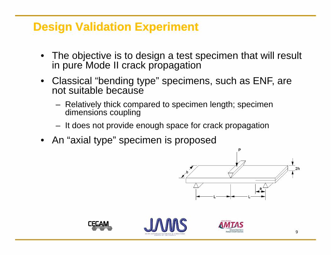
Design Validation ExperimentDesign Validation Experiment
• The objective is to design a test specimen that will result in pure Mode II crack propagation Classical “bending type” specimens such as ENF are• Classical bending type specimens, such as ENF, are not suitable because– Relatively thick compared to specimen length; specimen
dimensions couplingdimensions coupling– It does not provide enough space for crack propagation
• An “axial type” specimen is proposedyp p p p
9

Design of Mode II Test Specimen V.1Design of Mode II Test Specimen V.1
• Axial-type specimen to test crack arrestment behavior– Allows sufficient length for crack to propagate
S t i 3 b i li i t li f• Symmetric 3-beam specimen eliminates coupling of bending and axial deformations that occur in 2-beam
• First proposed specimen is a 3-beam model with load p p papplied to the center beam
10

Mode II Test Specimen V.1 Mode II Test Specimen V.1 -- Preliminary FindingsPreliminary Findings
• 3-Beam with center loaded results in mixed mode crack propagation– Configuration results in opening momentConfiguration results in opening moment
at crack tip
11
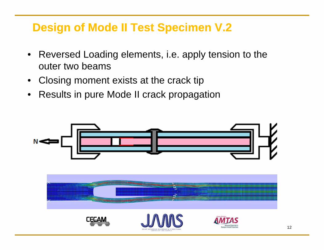
Design of Mode II Test Specimen V.2Design of Mode II Test Specimen V.2
• Reversed Loading elements, i.e. apply tension to the outer two beamsCl i t i t t th k ti• Closing moment exists at the crack tip
• Results in pure Mode II crack propagation
12
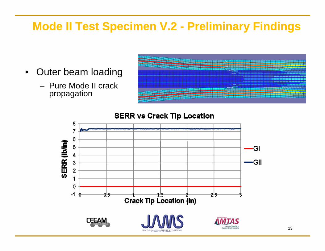
Mode II Test Specimen V.2 Mode II Test Specimen V.2 -- Preliminary FindingsPreliminary Findings
• Outer beam loading– Pure Mode II crack
propagation
13

Analytical vs. FEM resultsAnalytical vs. FEM results
• Analytical and FEM results show good correlationLoad vs. Crack Length
(3 x 24-ply quasi-isotropic laminates)
70000
80000(3 x 24 ply quasi isotropic laminates)
40000
50000
60000
d (lb
)
20000
30000
40000
Load
GIIC=7 (Abaqus)
GIIC=7 (Analytical)
0
10000
0 0 5 1 1 5 2 2 5 3
GIIC=7 (Analytical)
GIIC=25 (Abaqus)
GIIC=25 (Analytical)
14
0 0.5 1 1.5 2 2.5 3Crack Length (in)
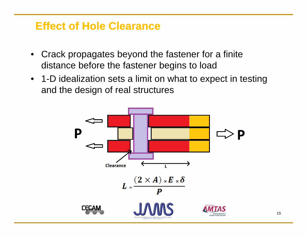
Effect of Hole ClearanceEffect of Hole Clearance
• Crack propagates beyond the fastener for a finite distance before the fastener begins to load
• 1-D idealization sets a limit on what to expect in testing and the design of real structures
15
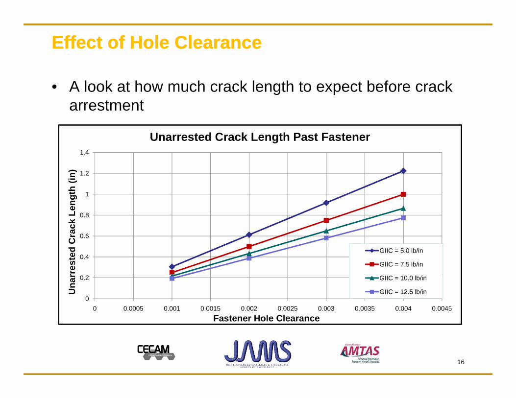
Effect of Hole ClearanceEffect of Hole Clearance
• A look at how much crack length to expect before crack arrestment
1 2
1.4
n)
Unarrested Crack Length Past Fastener
0.8
1
1.2
ck L
engt
h (in
0.4
0.6
rres
ted
Cra
c
GIIC = 5.0 lb/in
GIIC = 7.5 lb/in
0
0.2
0 0.0005 0.001 0.0015 0.002 0.0025 0.003 0.0035 0.004 0.0045
Una
r
Fastener Hole Clearance
GIIC = 10.0 lb/in
GIIC = 12.5 lb/in
16

Design of the Prototype SpecimensDesign of the Prototype SpecimensS i f t d b B i• Specimens are manufactured by Boeing
17

Prototype Specimen DetailsPrototype Specimen Details
• 24-ply quasi-isotropic laminate with 0/90 fabric on top and bottomS i i t t th i d b di• Specimen is put together using secondary bonding
• ¼” Titanium fastener installed at half installation toque: 40 in-lb40 in lb
• Initial cracks are implanted at the secondary bonding interface with Teflon inserts
18

Prototype Specimen TestingPrototype Specimen Testing
S i t t d i t i I t t t hi• Specimens are tested in tension on Instron test machine• Crack initiation is followed by ultimate failure
– Filled/Empty-hole tension failure of the outer laminatesFilled/Empty hole tension failure of the outer laminates
• Bridging observed, crack jumps from the bondline to a couple plies into the outer laminates
• Fracture toughness of the secondary bond is too high
19

Composite Specimen Composite Specimen DelaminationDelamination InspectionInspection
• C-Scan of tested specimens for fastener vs. no fastener• Fastener affects the growth of cracksg
With fastener
Without fastener
20
Prototype Specimen SummaryPrototype Specimen Summary
• Analytical method and FEM were used to design Mode II specimenC k i iti ti l d i hi h th th lti t f il• Crack initiation load is higher than the ultimate failure load of the outer laminates
• The prototype Mode II specimen shows that the fastenerThe prototype Mode II specimen shows that the fastener affects crack propagation
• Competing failure modes (filled hole tension) must be dd daddressed– Decrease GIIc; co-cured vs. secondary bond– Adjustment to geometry; increase w/a, increase thicknessj g y– Change center/outer laminate stiffness
21
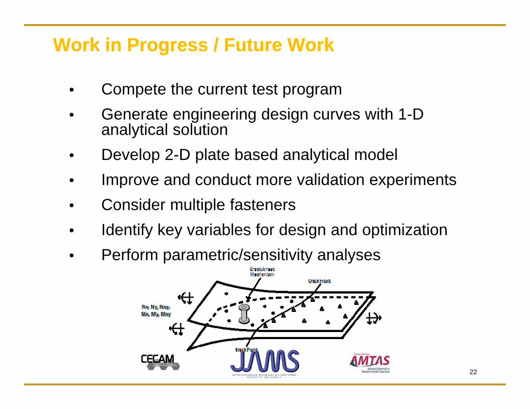
Work in Progress / Future WorkWork in Progress / Future Work
• Compete the current test program• Generate engineering design curves with 1-D
analytical solutionanalytical solution• Develop 2-D plate based analytical model• Improve and conduct more validation experiments• Improve and conduct more validation experiments• Consider multiple fasteners• Identify key variables for design and optimization• Identify key variables for design and optimization• Perform parametric/sensitivity analyses
22

A Look ForwardA Look Forward
Benefit to Aviation
– Provide analysis tools for fastener arrest mechanismProvide analysis tools for fastener arrest mechanism
– Provide a fail-safe path to the design of integrated
it t tcomposite structures
– Optimization can lead to weight savings while
properly addressing safety issue
– Integrating with probabilistic analysis method canIntegrating with probabilistic analysis method can
properly address design uncertainties
23

AcknowledgementsAcknowledgements
This study was supported by the FAA through the AMTAS (Advanced Material for Transport Aircraft Structures)at the University of Washington, and The Boeing Company. The FAA technical monitors are Ms. Lynn Pham, Mr. Curt Davies and Dr. Larry Ilcewicz. The Boeing technical monitor is Marc Piehl. Other Boeing technical personnel involved are E i C d G ld M b Th i t d l blEric Cregger and Gerald Mabson. Their support and valuable discussions are appreciated. Additional thanks to Bill Kuykendall at the University of Washington for his assistanceKuykendall at the University of Washington for his assistance with experimentation.
24

Thank YouQ i ?Questions?Comments?
Suggestions?
25