mars or bust, llc - university of colorado boulder · pathfinder ares vallis region 19.33° n,...
TRANSCRIPT

MARS OR BUST, LLC
Page 14 of 264
Figure 2.3: General Layout of Habitat
3 Mars Environment and In-Situ Resource Utilization
3.1 Mars Environment Overview
The Mars Environment subsystem’s main objective was to collect all environmentalparameters for the surface of Mars and show how it pertains to the surface habitat. AMars Environment Information Sheet (MEIS) was created and distributed to all othersubsystems to ensure that consistent parameters were used throughout the design. Theteam was responsible for working with all other subsystems to ensure that the habitatwould operate successfully for the entire mission duration under all Martianenvironmental extremes.
3.2 Mars Environment Parameters
The environmental parameters for Mars are given as ranges across the entire planet.Subsystems thus used the worst case parameters for their designs. A more accurate set ofdata can be used once an exact landing site or a range of latitudes is specified. Table 3.1

MARS OR BUST, LLC
Page 15 of 264
lists some key Mars environment parameter. Refer to the MEIS in Appendix C for moreinformation.
Table 3.1: Mars Environment Parameters
3.2.1 Atmosphere
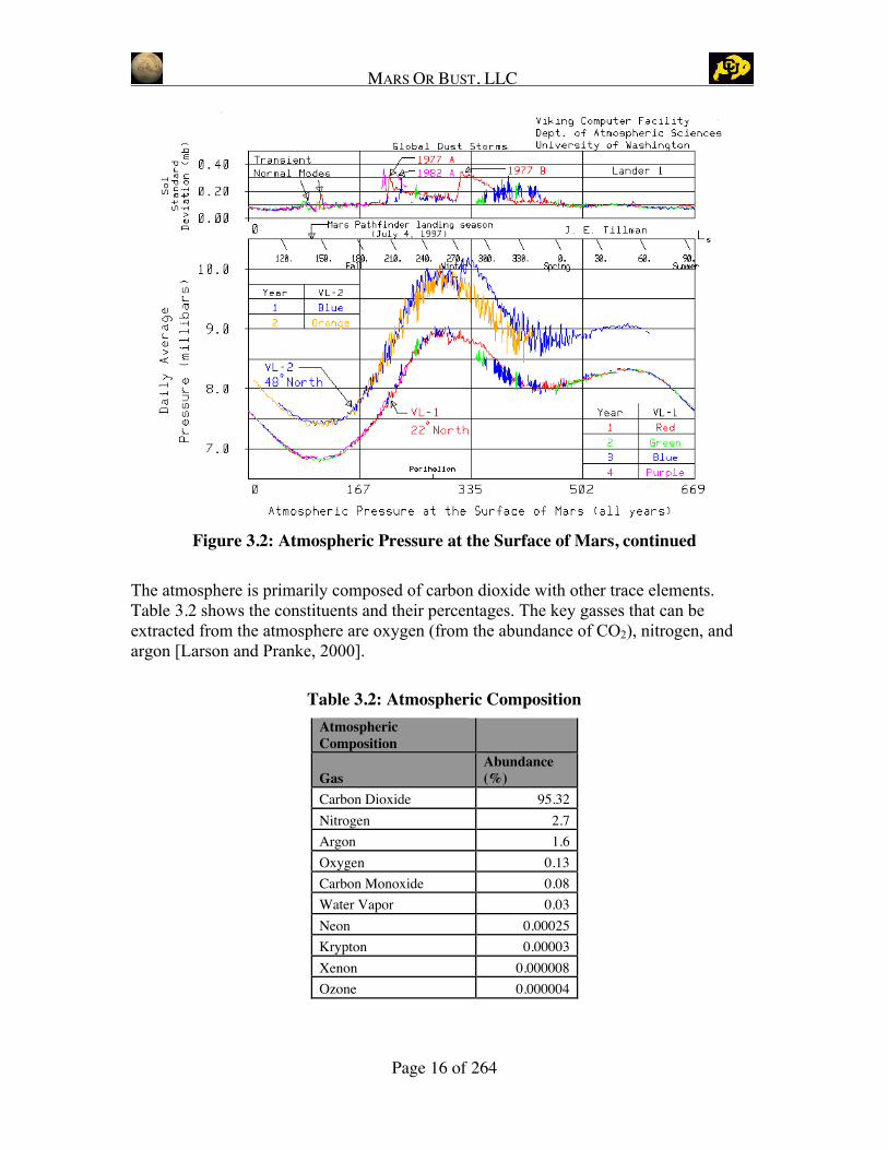
The low density of the Martian atmosphere is given in the range of 5-10 millibar (0.0049-0.0099 atm) with an average of 8 millibar (0.0079 atm) [Mars Academy, 2003; StarrySkies, 2003].
The following graphs show the atmospheric pressure at the surface of Mars for VikingLanders 1 and 2 over the respective mission duration durations. Note that the MarsPathfinder landing season (July) is noted on each graph for comparison [Tillman, 2003].
Figure 3.1: Atmospheric Pressure at Surface of Mars
Parameters Maximum Minimum AverageGravity (m/s2) 3.758 3.711 3.735Atmosphere Pressure (mbars) 10 4 8Surface Temperature (C) 27 -143 -63Radiation Skin dose (BFO)(cSv/day)
24.7(22.3)
21.2(19.7)
Wind Speeds (kph) 36 0 Wind Storm Speeds 127
MARS OR BUST, LLC
Page 16 of 264
Figure 3.2: Atmospheric Pressure at the Surface of Mars, continued
The atmosphere is primarily composed of carbon dioxide with other trace elements.Table 3.2 shows the constituents and their percentages. The key gasses that can beextracted from the atmosphere are oxygen (from the abundance of CO2), nitrogen, andargon [Larson and Pranke, 2000].
Table 3.2: Atmospheric CompositionAtmosphericComposition
GasAbundance(%)
Carbon Dioxide 95.32Nitrogen 2.7Argon 1.6Oxygen 0.13Carbon Monoxide 0.08Water Vapor 0.03Neon 0.00025Krypton 0.00003Xenon 0.000008Ozone 0.000004
MARS OR BUST, LLC
Page 17 of 264
3.2.2 Temperature ranges
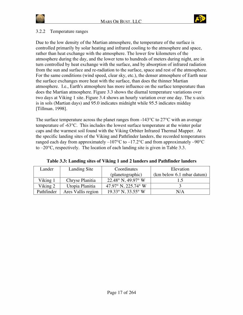
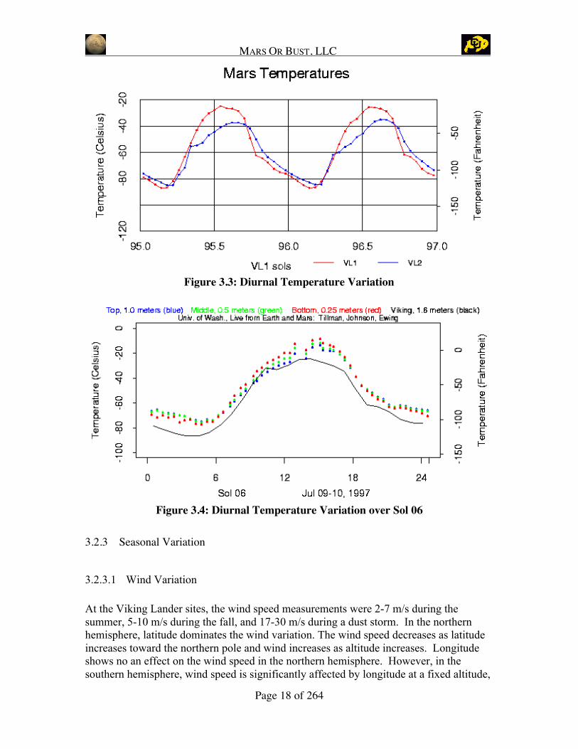
Due to the low density of the Martian atmosphere, the temperature of the surface iscontrolled primarily by solar heating and infrared cooling to the atmosphere and space,rather than heat exchange with the atmosphere. The lower few kilometers of theatmosphere during the day, and the lower tens to hundreds of meters during night, are inturn controlled by heat exchange with the surface, and by absorption of infrared radiationfrom the sun and surface and re-radiation to the surface, space and rest of the atmosphere.For the same conditions (wind speed, clear sky, etc.), the denser atmosphere of Earth nearthe surface exchanges more heat with the surface, than does the thinner Martianatmosphere. I.e., Earth's atmosphere has more influence on the surface temperature thandoes the Martian atmosphere. Figure 3.3 shows the diurnal temperature variations overtwo days at Viking 1 site. Figure 3.4 shows an hourly variation over one day. The x-axisis in sols (Martian days) and 95.0 indicates midnight while 95.5 indicates midday[Tillman, 1998].
The surface temperature across the planet ranges from -143°C to 27°C with an averagetemperature of -63°C. This includes the lowest surface temperature at the winter polarcaps and the warmest soil found with the Viking Orbiter Infrared Thermal Mapper. Atthe specific landing sites of the Viking and Pathfinder landers, the recorded temperaturesranged each day from approximately –107°C to –17.2°C and from approximately –90°Cto –20°C, respectively. The location of each landing site is given in Table 3.3.
Table 3.3: Landing sites of Viking 1 and 2 landers and Pathfinder landersLander Landing Site Coordinates
(planetographic)Elevation
(km below 6.1 mbar datum)Viking 1 Chryse Planitia 22.48° N, 49.97° W 1.5Viking 2 Utopia Planitia 47.97° N, 225.74° W 3
Pathfinder Ares Vallis region 19.33° N, 33.55° W N/A
MARS OR BUST, LLC
Page 18 of 264
Figure 3.3: Diurnal Temperature Variation
Figure 3.4: Diurnal Temperature Variation over Sol 06
3.2.3 Seasonal Variation
3.2.3.1 Wind Variation
At the Viking Lander sites, the wind speed measurements were 2-7 m/s during thesummer, 5-10 m/s during the fall, and 17-30 m/s during a dust storm. In the northernhemisphere, latitude dominates the wind variation. The wind speed decreases as latitudeincreases toward the northern pole and wind increases as altitude increases. Longitudeshows no an effect on the wind speed in the northern hemisphere. However, in thesouthern hemisphere, wind speed is significantly affected by longitude at a fixed altitude,

MARS OR BUST, LLC
Page 19 of 264
local standard time, and latitude. For example, at 20°E longitude the typical wind speedis 50 m/s westward compared to 120 m/s eastward at 335°E. At night, wind speeds differfrom the daytime values but with less variation than during the day. [Withers, 2002;NASA, 1998]
3.2.3.2 Seasonal Temperature Variations
From winter to summer at the Viking Lander Site the temperature ranged from -107 °C to-18°C [Larson and Pranke, 2000]. The Mars Global Surveyor Radio Science Instrumentmeasured the temperature seasonal range from –128°C to –28°C [Stanford, 1999].
3.2.3.3 Maximum Gradients
Diurnal temperature varies from -89 to -31 °C as noted at the Viking Lander 1 site[NASA, 2003]. Peak temperature gradients in the morning can reach up to 20 °C perminute with a 15 °C temperature range between the ground and an altitude of 2 m.
Table 3.4: Mars Environment Seasonal ParametersNorthern Hemisphere Seasons and Temperature Ranges
SeasonDuration
(Sols) Temperature RangesWind Speeds
(m/s)Spring 194 TBD Summer 178 -123 to -63 C summer and fall 2 to 7Autumn 143 5 to 10Winter 154 -107 to -18 C winter and spring TBD
3.2.4 Radiation
The Martian atmosphere provides substantial radiation shielding for a surface habitat.Other considerations in the design should include using water tanks and food supplies toline the inside of the habitat walls to reduce daily radiation levels inside the habitat. Thisuse of habitat resources will give adequate radiation protection from solar particle events.Galactic Cosmic Ray (GCR) events are more detrimental to the habitat computers and thecrew than solar radiation. The average radiation dosage is about 1.2 mSv/day on Marsorbit. The average dosage in low Earth orbit is 0.5 mSv/day [NASA Photojournal, 2003].
3.2.4.1 Galactic Cosmic Ray Dose
As indicated in recent research [Simonsen, 1993], an astronaut staying on the surface ofMars for 677 days will have a skin dose equivalent of 21.2 cSv for high CO2 density and24.7 cSv for low CO2 density in the atmosphere. The Blood Forming Organ (BFO) Dose

MARS OR BUST, LLC
Page 20 of 264
equivalent is 19.7 cSv (high density) to 22.3 cSv (low density). (These calculations weremade for a mission arrival on 10/1/2018 and departure on 8/8/2020). Low Earth orbitlimits are 50 cSv annually for BFO dose and 300 annually for Skin dose, so these BFOdose numbers are acceptable. These dose estimations assume no shielding other than CO2in the atmosphere. Solar radiation will add to the dose received. [Simonsen, 1993]
3.2.4.2 Solar Particle Event Dose
For the worst case, an average radiation level of less than 5 cSv/year is experiencedduring solar maximum [Simonsen, 1993].
3.3 Future Considerations
Mars creates a difficult environment for a surface habitat as well as humans. For a moreaccurate design analysis of the different subsystems, the landing site or area must bespecified. Subsystems used the worst case parameters for their designs. In the nextdesign iteration, an exact landing site or a range of latitudes should be specified.
The Martian atmosphere shields the habitat and crew from much of the radiation, but dueto the risk of GCRs or SPEs, other shielding designs should be considered. A safe havenconsisting of a thick wall of Martian soil next to the habitat with could provide radiationprotection during high radiation events. An adequately sized wall section can be built oneach side of the middle of the habitat to house 6 crew members during a GCR event.Refer to Section 4 for more information on radiation shielding.
The effect of 1/3 gravity on structures, pumps, and humans has not been well documentedand only minor experiments accomplished with reference to Mars gravity. Theinformation on the long-term effects of the Martian environment is limited and will needto be investigated further.
4 In-Situ Resource Utilization
4.1 Level 2 Requirements
The responsibility of the in-situ resource utilization (ISRU) team was to design theinterfaces between the ISRU propellant production plant (ISPP) and the habitat. The ISPPwill provide additional reserve of 4.5 tonnes of oxygen, 3.9 tonnes of nitrogen and 23.2tonnes of water, as specified by the DRM [Hoffman and Kaplan, 1997]. For the surfacehabitat designed in this document, all consumable mass is being brought with the habitat.The ISPP plant will demonstrate that these consumables can be produced in a timely,efficient manner. This demonstration will be monitored and will be used primarily to

MARS OR BUST, LLC
Page 21 of 264
save mass for future missions to Mars. The consumable reserve may be used by the firstcrew if it is needed. The team also evaluated use of additional in-situ resources. Table4.1 lists the level 2 requirements for the ISRU subsystem.
Table 4.1: Level 2 Requirements
# Requirement Description Source4.1 Provide additional 3.9 tonnes of nitrogen, 4.5 tonnes of oxygen,
and 23.2 tons of waterDRM 3.6.4.3
4.2 Byproducts of the propellant production shall be used as backupNitrogen, Oxygen, and Water
DRM 1.3.3.2
4.3 Storage tanks and pipes for the ISRU shall tolerate leaks withinlimits
Derived
4.4 Propellant production shall be automated DRM 1.3.3.24.5 Temperature shall be maintained in all interfaces Derived4.6 All interfaces must be compatible with habitat Derived4.7 Pumping systems shall have adequate power to transport oxygen,
nitrogen and water to habitatDerived
4.8 All interfaces must have adequate shielding from the Marsenvironment
Derived
4.9 Interfaces to storage tanks and ISRU tanks can be performed byeither robots or humans
Derived
4.10 Interfaces must be tolerant to multiple failures and have properfailure prevention so it will not adversely affect the consumables
Derived
The above requirements are derived from the level 1 requirements stated in the DRM.From here, the basics of an ISRU subsystem can be established. The ISRU subsystem isthe interface between the ISRU plant and the habitat and must transfer all consumables tothe crew whenever needed. A schematic of the consumables flow from the ISRU plant tothe ECLSS storage tanks can be seen in Figure 4.1. Also shown in this flow chart is thepower input to the ISRU subsystem, the heat flow to the thermal subsystem, hydrogenflow from the ECLSS subsystem, the telemetry to the C3 subsystem, and commands fromthe C3 subsystem.

MARS OR BUST, LLC
Page 22 of 264
Figure 4.1: Input / Output Diagram
4.2 Interface Design
The ISRU interface consists of a connection point for the ISPP. Pipes that are used totransfer oxygen, nitrogen, water, and hydrogen all connect to this interface. Additionally,connection points for telemetry, commands, and electrical power are present. While themain method of communication with the ISPP will be radio communications, a wiredback-up connection point is included. Electrical power will be required to heat the waterpipes between the habitat and ISPP. Also included in this interface are the pumps andpipes necessary to connect to the ISPP. The ISRU functional subsystem schematic isshown below in Figure 4.2.
The ISPP is required to produce a total of 3900 kg of nitrogen, 4500 kg of oxygen, and23000 kg of water before the crew arrives as per the DRM [Hoffman and Kaplan, 1997].These consumables are to be transferred to the habitat as needed. The pipes that are to beused must be well insulated and minimize the amount of leakage.
C3
ECLSS
Thermal
Power
Robotics/Automation
Structures
CrewAccommodations
Crew
EVAS
ISRU
ISRUPlant
NuclearReactor
Mars Environment
MarsCom
Satellites Habitat Boundary
OxygenNitrogenCO2Cabin AirTrace Contam.H20 VaporH2Potable H20Non-Pot. H20Solid WasteLiquid WasteFoodTelemetryVideoAudioPacket. DataTCP/IPCommandHeatElectric. Power
MOB Habitat Overall Subsystem Functional Diagram

MARS OR BUST, LLC
Page 23 of 264
Figure 4.2: ISRU Functional Subsystem Schematic
DynaFlex LN2 piping designed specifically for use with cryogenic gasses will be used forthe hydrogen, oxygen, and nitrogen [VBS, 2003]. The water pipe will be similar, but willhave an electrical heater coil in addition to insulation to keep the liquid from freezing.Once the ISRU plant is moved to within 50 m of the habitat, the piping can be connected.Estimated mass for 50 m of piping for each consumable to be transferred is shown inTable 4.2.
Table 4.2: Mass, Power, Volume Breakdown
Component #
TotalWeight
(kg)Power
(W)Volume
(m3)Water Pump 1 70.5 70.5 TBDOxygen Pump 1 0.94 1.5 TBDNitrogen Pump 1 0.94 1.5 TBDWater Pipe 1 80 0 0.65Oxygen Pipe 1 70 0 0.65Nitrogen Pipe 1 70 0 0.65Hydrogen Pipe 1 70 1.5 0.65
Valves and Connections 10 52 5 TBD
Totals 414.38 80 2.6

MARS OR BUST, LLC
Page 24 of 264
The ISPP arrives with the cargo lander 450 days prior to the arrival of the crew. Thisresults in an estimated production rate of consumables of 8.39 kg/day of nitrogen, 9.68kg/day of oxygen, and 49.46 kg/day of water. During the crewed mission, the ISRUinterface will need to transfer these consumables to the habitat. Flow rates were kept lowto reduce the size of pipes and pumps that are needed. An estimate of 864 kg of nitrogenand oxygen per transfer and 2700 kg of water results in a total of 5 transfers of nitrogen,6 transfers of oxygen, and 9 transfers of water during the mission. Each transfer fornitrogen and oxygen occurs over the course of one day, while the transfer of water occursover one hour. These transfer times were chosen to also minimize the power and size ofthe pumps. Assuming leakage rates from the valves and pipes are minimal, this shouldbe sufficient to transfer the consumables to the habitat.
Table 4.3: Properties and flow rates of consumables
ConsumableDensity(kg/m3)
SpecificHeat
(J/(kg*K)
KinematicViscosity
(m2/s)
AbsoluteViscosity
N*s/m2Flow Rate
(m3/s)Mass FlowRate (kg/s)
Nitrogen at 100 K 3.48 1072.2 1.97E-06 6.86E-06 0.00287356 0.01
Oxygen at 100 K 3.992 947.9 1.95E-06 7.77E-06 0.00250501 0.01
Water at 293 K 1000 4181 1.79E-06 1.79E-03 0.00075 0.75
To calculate the power required to pump these fluids, a few assumptions and estimateswere made. The first of which is the total head of the piping system. In addition to the50 meters of piping, there are duplicate sets of sequential valves on each end of the pipesto prevent accidental depressurization of the habitat or ISRU storage tanks. Each valveadds additional head, which the pumps have to overcome. Since the specific design ofthe piping and valve system needs to be established before a real design calculation canbe done, an estimate of an additional 100 meters of head was included. The power ofeach pump can be estimated as the product of a head of 150 meters, the density of eachconsumable, and the flow rate required. Total power required for each pump is shown inTable 4.2. There is not a hydrogen pump included in the ISRU interface, as it will be partof the ECLSS system. Table 4.3 lists some properties of the consumables, volume flowrates, and mass flow rates.
4.3 Operations
Although the ISRU interface will be fully automated, occasionally crew inspection andmaintenance will be needed. Table 13.2 shows estimated operations required for theISRU interface. Since the interface design in not complete, the operations will be subjectto major modifications. An important note is that if the connection of the pipes to theISRU Plant cannot be accomplished by the robots, it must be done by an EVA. Thisraises safety concerns for the crew.

MARS OR BUST, LLC
Page 25 of 264
4.4 Summary of ISPP Plant Designs and Processes
Different methods have been proposed for utilizing in-situ resources on Mars, all ofwhich use the carbon and oxygen present in the atmosphere in the form of carbondioxide. Generally, the Martian carbon is used in combination with hydrogen broughtfrom Earth to form hydrocarbon fuel. This hydrocarbon fuel is essential for the trip fromMars back to Earth. To bring enough fuel from Earth for the return trip would increasethe needed launch mass many fold. For every kilogram of material sent from Mars backto Earth with in-situ propellant, there is a savings of hundreds of kilograms of fuel thatwould have had to be launched into Earth orbit. This means that ISRU will be anessential part of any feasible Mars mission. Also, the Martian oxygen can be used tokeep humans alive, or as propellant. Several methods could be used to extract theseresources, as described in Larson and Pranke, 2000.
4.4.1 Zirconia Electrolysis
Zirconia Electrolysis is a process whereby O2 is stripped from CO2 as shown in Figure4.3. Zirconia Electrolysis requires large amounts of heat to split the CO2 into CO and O2.At around 1000°C, the reaction proceeds at a reasonable speed. Once this is done,applying an electric charge across the zirconia tubes facilitates the extraction of pure O2.This process is simple, but requires a lot of energy and many fragile zirconia tubes.
Zirconia Electrolysis
Zirconia-walled Reactor
1000 °CCO2
CO + CO2
O2
Heat
Advantages•Simple operation•Produces Oxygen
Requires 1562 W -day/kg of Oxygen
Zirconia Electrolysis
Zirconia-walled Reactor
1000 °CCO2
CO + CO2
O2
Heat
Advantages•Simple operation•Produces Oxygen
Requires 1562 W -day/kg of OxygenFigure 4.3: Zirconia Electrolysis
4.4.2 Sabatier Electrolysis
Sabatier Electrolysis is a more complicated process, but it produces both fuel andoxidizer from the Martian atmosphere that can be used as rocket propellants (see Figure4.4). It requires a supply of hydrogen, which is mixed with carbon dioxide and heated inthe presence of a catalyst. A reaction takes place which releases methane and water. The

MARS OR BUST, LLC
Page 26 of 264
water can be shunted through an electrolysis process to separate the hydrogen andoxygen. The hydrogen is recycled through the process and the oxygen and methane arestored cryogenically to be used as propellants and for human respiration. The problem isthat oxygen and methane are produced in a 2:1 mass ratio, while a mass ratio of 3.5:1 isrequired for proper combustion in a rocket engine.
H2
Nickel Catalyst 400 °C
H2 + CO2
CH4
H2O
Heat
Electrolysis O2
Power
Figure 4.4: Sabatier Electrolysis
4.4.3 Reverse Water Gas Shift - Oxygen
Another way to extract oxygen from the Martian atmosphere is called the Reverse Water-Gas Shift (RWGS). This reaction takes place at about 400°C in the presence of a catalyst(different than the Sabatier catalyst) and produces carbon monoxide and water (seeFigure 4.5). The carbon monoxide is discarded and the water can be separated throughelectrolysis to obtain oxygen. The initial supply of hydrogen is recycled endlessly and noadditional hydrogen is required to keep the process going. RWGS can be used incombination with Sabatier electrolysis to obtain the proper fuel/oxidizer ratio for rocketengines. By sizing the RWGS system a little bigger, extra breathing oxygen can besupplied for a Mars surface crew. The heat released from the Sabatier electrolysis can beused to keep the RWGS process hot enough to proceed without an additional source ofheat.
Requires 1562 W-day/kg of Oxygen

MARS OR BUST, LLC
Page 27 of 264
H2
Iron-Chrome Catalyst 400 °C
H2 + CO2
CO
H2O
Heat
Electrolysis O2
Power
Figure 4.5: Reverse Water Gas Shift to produce Oxygen
4.4.4 RWGS - Ethylene
Instead of discarding the carbon monoxide from the RWGS process, it can be combinedwith hydrogen and a Fischer-Tropsch catalyst to form ethylene and water (see Figure4.6). The water can be used to supply the oxygen needs and the ethylene makes a goodrocket fuel that doesn't require cryogenic refrigeration. The heat released in the ethylenereactor can provide the energy needed for the RWGS reaction to proceed. Ethylene isdenser than methane, so propellant tanks could be smaller. Ethylene also has an Ispslightly higher than methane and has less hydrogen atoms per carbon atom, meaning thatless hydrogen needs to be brought from Earth.

MARS OR BUST, LLC
Page 28 of 264
H2
Iron-Chrome Catalyst 400 °C
6H2 + 2CO 22CO
2H2O
Heat
Electrolysis O2
Power
4H2 Fischer-TropschCatalyst
2H2O
C2H4
Figure 4.6: Reverse Water-gas Shift and an Ethylene Reactor
4.4.5 RWGS - Methanol
A different catalyst in the ethylene reactor would produce methanol. Methanol burnscooler than ethylene, but has a lower Isp. It requires less oxygen than methane and doesnot need to be cryogenically stored.
4.4.6 ISPP Trade Study
The different ISRU processes are summarized in Table 4.4. The DRM specifies that theSabatier electrolysis process be used to create methane and oxygen with the Zirconiaelectrolysis process providing the extra oxygen needed to achieve the ideal mixture ratioand to provide extra oxygen for humans. These two processes were probably chosenbecause they have been tested with prototype plants. However, the other ISRU processesshould be considered because they could be much more energy efficient. Besidescreating fuels, the DRM specifies that water, oxygen, and nitrogen be provided by ISRUprocesses. Sabatier electrolysis could be used to produce the extra water and bothSabatier and Zirconia plants could be used to provide the extra oxygen needed forhumans. Nitrogen, which is also present in the Martian atmosphere, could be extracted aswell for use as a buffer in the habitat atmosphere.

MARS OR BUST, LLC
Page 29 of 264
Table 4.4: ISPP Trade Study
ISRU Plant TypeW/kg ofproduct Products Advantages Disadvantages
ZirconiaElectrolysis
1710 O2 Simple operation Many fragile tubesrequired
SabatierElectrolysis
307 CH4O2 (H2O)
High Isp Requires H2Cryogenic StorageNon-ideal mixture ratio
RWGS Methane 307 CH4O2 (H2O)
Ideal mixture ratio Requires H2Cryogenic Storage
RWGS Ethylene 120 C2H4O2 (H2O)
Non-cryogenicHigh Isp
Requires _ x H2
RWGS Methanol 120 CH3OHO2 (H2O)
Non-cryogenicLow flame Temp.
Requires H2Lower Isp
4.5 Benefits of ISRU for Future Missions
All consumables other than food can be taken from the Mars environment. The totalachievable mass savings for a stay of 600 days and supplying 6 people is expected to be11,435 kg. The mass savings is calculated from the difference between 11,850 kg(consumable mass for 600 days for 6 people as indicated by the ECLSS subsystem) and415 kg (mass of the ISRU interface).
4.6 Additional Martian Resources – Water and Soil
Mars Global Surveyor has confirmed the presence of large amounts of water on Mars. Ifthis water (in the form of ice) can be collected and refined, it can supply a vital resourcefor a Martian habitat. Ice will probably be hard to find, collect, and refine, and its usewill not be practical in early missions. Early manned missions to Mars will probablysearch for good sources of water ice, but will have to take enough water to supply all oftheir needs. Water extraction from Mars will have to wait until future missions can bringthe right equipment before the benefits of in-situ water can be utilized.
Martian soil can be a very efficient way to build radiation shielding or provide otherforms of insulation. Soil could either be poured into bags, sandbag style, or combinedwith water and heated in a kiln to form bricks. Making bricks would require a largeinvestment in massive equipment, while the sandbags would be limited to the number ofempty bags brought along. All of this will probably not be required because the Martianatmosphere provides a reasonable amount of shielding from radiation. Shielding made ofMartian soil could be used for the return journey to Earth, but it still would have to be

MARS OR BUST, LLC
Page 30 of 264
launched up from the Martian surface, which would be an inefficient process. Soil, justlike ice, will not be practical to use until later missions to Mars. Perhaps later Marsmissions could take advantage of the abundant iron, silicon, and other metals in the soilas well.
4.7 Verification of Requirements
The verification of the ISRU interface requirements is summarized in Table 4.5. TheISRU subsystem design meets most of our requirements at a functional level. Several ofthe requirements regarding the ISRU consumable production, such as 4.1, 4.2, and 4.4would need to be addressed by the design of the ISPP itself, which was not within thescope of this design. The oxygen, nitrogen, and water from the ISPP will be transferredto the habitat through the ISRU interface, which is designed to transfer the consumablessafely under the right temperature and pressure while maintaining leaks below specifiedlevels. The ISRU interface will also be able to survive the Martian environmentalconditions. As an important safety precaution, properly positioned valves will keep anyfailures in the ISRU interface from compromising the consumables stored in the ECLSSsystem. However, a more detailed design will be required to assure that either robots orhumans can make the proper connections between the ISRU plant and the habitat. Inaddition, the total system mass should be evaluated to determine if mass savings arepossible through the use of alternative designs or technologies.
Table 4.5: Verification of Requirements
# Requirement Description Design4.1 Provide additional 3.9 tons of nitrogen,
4.5 tons of oxygen, and 23.2 tons ofwater
Extract 3.9 Tons N2, 4.5 Tons O2,from Mars atmosphere, combine H2(supplied) with O2 to make 23.2 tonsof water
4.2 Byproducts of the propellant productionshall be used as backup Nitrogen,Oxygen, and Water
Use In-Situ Resource PropellantProduction plant to provide, ISPP willprovide the H2 to make requiredwater
4.3 Storage tanks and pipes for the ISRUshall tolerate leaks within limits
Purge pipes when not transferring tohabitat to reduce leakage
4.4 Propellant production shall beautomated
Commands and telemetry sent toISPP plant when extra consumablesare needed
4.5 Temperature shall be maintained in allinterfaces
Heaters will be supplied to the waterpipe line to ensure no freezing, ISPP& ECLSS will provide its owncooling/heating system for tanks
4.6 All interfaces must be compatible withhabitat
Future Task
4.7 Pumping systems shall have adequatepower to transport oxygen, nitrogen andwater to habitat
500 W provided to the ISRUsubsystem is adequate for the lowmass flow rate pumping needs
4.8 All interfaces must have adequateshielding from the Mars environment
Insulation coating (TBD) on each 50mpipe, future task to bury pipesunderneath the surface for radiationprotection
4.9 Interfaces to storage tanks and ISRUtanks can be performed by either robotsor humans
Future Task

MARS OR BUST, LLC
Page 31 of 264
or humans
4.10 Interfaces must be tolerant to multiplefailures and have proper failureprevention so it will not adversely affectthe consumables
Multiple valves in sequence
4.8 Future Considerations
ISRU will save mass for future missions and could make a Mars colony much moreaffordable. A more detailed design of the interface should be conducted after moreinformation on the ISRU plant is available. Multiple design iterations could reduce massand increase reliability in the subsystem design. The recommended ISRU plants in theDRM might not necessarily be the best option. A trade study to specify the propellantproduction process should be performed to assure that the optimal ISRU process is used.This could require building some prototype plants for competing processes and collectingdata on their performance. These development studies would help establish properconsumable production rates and power requirements.
5 Structures Subsystem
5.1 Overview
The structures subsystem provides the pressurized volume required for the human habitat.It will contain the crew and incorporate all subsystems necessary to provide for the crewand the mission, provide radiation and micro-meteoroid shielding, and withstand allloading environments.
5.2 Level 2 Requirements
Table 5.1 lists the structures requirements derived from and directly from the DRM[Hoffman and Kaplan, 1997]. This initial design focused on fitting within the launchshroud and supporting the habitat mass in worst case loading environments. Radiationshielding was also considered, both independently and in the layout design.
Table 5.1: Level 2 Requirements# Requirement Source5.1 Habitat shall fit within the dynamic envelope of the launch
vehicle.Derived
5.2 Habitat must be structurally sound in all loadenvironments (acceleration, pressure, etc.).
Derived
5.3 Habitat structure must stably support all subsystemcomponents.
Derived
5.4 Habitat must withstand all seismic activity on Mars. Derived5.5 Habitat structure must provide radiation shielding. Derived

MARS OR BUST, LLC
Page 32 of 264
5.6 Habitat must withstand radiation accumulation. Derived5.7 Habitat must withstand micrometeor impacts. Derived5.8 Habitat structure must provide thermal insulation. Derived5.9 Habitat must withstand the Martian Atmospheric
conditions.Derived
5.10 Habitat and equipment must withstand dust accumulation. Derived5.11 Habitat shall maintain stability on Martian Soil. Derived5.12 Habitat must be able to land, setup, and move over
varying topography at landing site.Derived
5.13 Habitat must not chemically react with soil. Derived5.14 Habitat structure must be accessible for repair. Derived5.15 Structures Mass shall not exceed 20744 kg. DRM
5.3 Input/Output Diagram
Figure 5.1: Input/Output Diagram for Structures subsystem.
Figure 5.1 shows the inputs and outputs of the Structures subsystem. Cabin air (includingheat and water vapor) escapes through the structure to the Martian environment. Heatmay also come into the habitat through the structure. Trace contaminants escape fromthe structure to the ECLSS subsystem and the Martian environment. Also, several loadand position sensors send telemetry to C3.

MARS OR BUST, LLC
Page 33 of 264
5.4 Design and Assumptions
5.4.1 Key Assumptions
Several assumptions were made for this design, since some aspects of the mission are notwell defined (i.e. landing site, launch vehicle, etc.) and not within the scope of this firstiteration design. It is assumed that the habitat will be launched in the Magnum vehicle, alaunch vehicle described in the DRM, but not actually designed. The launch loads of thisvehicle are assumed to be similar to the Atlas V. It is also assumed that this vehicle willprovide micrometeoroid protection and radiation protection for the habitat during transit.The landing vehicle is also not well defined, nor within the scope of this design. Thelanding loads are assumed to be similar to those on the Pathfinder lander.
The Mars environment parameters currently available from previous and current missionsare assumed to be accurate for the site of the habitat or representative of the absoluteextremes that might be encountered. It is also assumed that a rover will be available onMars to move the habitat to its resting position and assist in its setup.
Lastly, for all support calculations, the mass of the habitat is assumed to be 50 tonnes.This mass reflects the maximum mass that the team felt was allowable for the 80 tonMagnum launch vehicle, considering that it would also carry a lander and propellant[Hoffman and Kaplan, 1997]. This mass was exceeded in the design, so thesecalculations may need to be adjusted if a more powerful launch vehicle is used.
5.4.2 General Layout of Mars Habitat
The layout of the habitat was designed with several considerations in mind. Theseconsiderations include: orientation, volume allocations, use of curved wall space, ease ofaccess, noise proximity, systems proximity, center of mass considerations, and radiationshielding. Figure 5.2 and Figure 5.3 below show the floor plans for the upper and lowerfloors of the habitat. Each floor is 2.25 m from floor to ceiling and the floors are only 6.2m wide, due to radiator storage and the curvature of the habitat.
Figure 5.2: Upper floor plan.

MARS OR BUST, LLC
Page 34 of 264
Figure 5.3: Bottom floor plan.
The personal space and crew accommodations (galley, wardroom, and hygiene) arelocated on the top floor. Each crew member has a 5 m2 (11.25 m3) private bedroomincluding a bed, personal storage and a small desk/workstation. Larson and Pranke[2000] recommend a minimum of 3 m3 per person for personal space, which is exceededin this design. There is a wardroom on one side of the personal rooms with a galley andstorage, and the area that is vacated by the airlock on the other side will also be used as awardroom and exercise room. The area near the galley will provide space for the entirecrew to eat together, and either space can be used for crew meetings and recreation.
The bottom floor will primarily be used for the lab. The space vacated by the airlocks onthe bottom floor will also be used for the lab. There is storage on both sides of this floor,as well as a safe haven and a medical/dental suite. The safe haven houses the C3
computers and will protect the crew during large solar events.
5.4.2.1 Orientation
The orientation of the habitat was chosen to be on its side. The reasoning for this isgreater stability as well as ease of movement in the habitat. The calculations for stabilitywill be gone into greater detail in section 5.4.3.2 below. If the habitat is a cylinder lyingon its side this means that there only needs to be two floors, instead of three to four thatwould be needed if it were used vertically. This layout allows the sectioning of thehabitat to be done based on a work/living area solution. The living quarters were putupstairs so that in order to get from outside collecting samples to the lab you don’t haveto walk through the living quarters. This arrangement may also be better psychologicallyfor the inhabitants. If the living quarters are separate from the work quarters then youwould get a better sense of being able to go “home” after work.
5.4.2.2 Volume Allocation

MARS OR BUST, LLC
Page 35 of 264
The volume allocation for each subsystem was determined based on the mass allocation.The mass for each subsystem was divided by the total mass of the structure to find outwhat percent of the total mass that subsystem accounted for. Then that percentage wasmultiplied by the total volume of the structure and adjusted for relative density to obtain arough estimate of the volume for that system. These volumes were then refined furtherby each of the subsystems. Table 5.2 below shows the volume allocation and use foreach of the subsystems.
Table 5.2: Volume allocation and designed volume of subsystems.
Subsystem
Volume Allocated
(m3)
Design
Volume (m3)
Structure 150 150
ECLSS 60 84
Consumables N/A
Thermal 40 14
EVAS 40 105
Robotics 15 0.6
Power 30 4.1
ISRU Interface 4 0.7
CCC 10 0.3
Crew Accommodations 50 46
Empty 217 211
Totals 616 616
Note that the volume for ECLSS does not include consumables under the allocatedvolume.
5.4.2.3 Use of Curved Wall Space
Due to the fact that the habitat is a cylinder the walls of the habitat will be curved. Someof this curved space is taken up by the radiator panels, which need to be folded in andstored during launch. The rest of the curved space will be used in several different ways.On the lab floor storage will be placed next to the walls and tables for the lab stations willextend from there. On the upper floor in the crew quarters the beds will be against thewalls so the curved space will not be a problem. In the other areas the area next to thewall will be used for storage space or in the kitchen for the food preparation areas.
5.4.2.4 Ease of Access
As alluded to above the decision to put the labs and the C3 equipment on the bottom floorand the living quarters on the top floor was driven by access considerations. In anemergency the C3 area will be in great use and should be near the exit points of thehabitat. There for having it on the bottom floor is a must. When bringing rock samplesand other items in from outside it would be good to be able to take them directly to where

MARS OR BUST, LLC
Page 36 of 264
they will be used which would be in the labs. This along with the fact that most of thedaytime activities will be done in the labs/communications center suggested that it shouldbe on the ground level.
5.4.2.5 Noise Proximity
One of the main driving factors in the design of the floor plan for the upstairs as well asanother reason to split the top and bottom floors as they are was noise proximity. Most ofthe loud equipment will be associated with the labs. This is another reason that the labswere put on the ground floor. The floor plan of the top floor was designed to keep theloud household items away from the sleeping quarters. These items include thedishwasher, washing machine, dryer, and shower. In an effort for these to have as littleeffect on the sleep cycle of the inhabitants as possible they are located on one end of thehabitat while the sleep quarters are as far away as possible.
5.4.2.6 Systems Proximity
Systems were placed so that most of the main components could be next to each other.This reduces the amount of piping, wiring, and other connections that need to be made.The shower, kitchen, and laundry facilities are all grouped together with the water tankslocated overhead in an attempt to decrease the amount of water piping that would beneeded in the habitat. The C3 and the lab equipment, which will be using most of thecomputing and communications abilities, are all located on the bottom floor of thathabitat which will help to reduce the amount of wiring.
5.4.2.7 Center of Mass Considerations
The center of mass (CM) of the habitat needs to be located on the axial center line of thecylinder. This minimizes the energy necessary to keep the spacecraft on its plannedtrajectory. The CM of the habitat will be closer to the propulsion system of the launchvehicle, rather than the nose. This, along with having the CM along the central axis ofthe cylinder will help to keep the vehicle stable. For launch and landing, the CM mustalso be behind the center of pressure.
In an effort to have the CM along the axial direction, the ECLSS tanks will be located inthe top of the structure to help offset the extra mass that will be needed in the supportstructure and trusses in the bottom of the structure. The top and bottom floor layouts aresomewhat symmetrical in order to keep the side-to-side masses equal. On the bottomfloor, the safe haven, which will be very heavy due to its required density, is located inthe center of the structure. This is for side-to-side balance issues. The three airlocks thatare located on the structure are centered side to side as well. The ECLSS water tanks andmost of the equipment that uses water are located at one end of the cylinder since it is thedensest system.

MARS OR BUST, LLC
Page 37 of 264
5.4.2.8 Radiation Shielding
The placement of the ECLSS tanks was done for radiation shielding reasons as well asthose stated above. If the tanks are on top of the habitat they will be able to provide moreshielding from cosmic rays. This in turn can reduce the weight of shielding that needs tobe added to the structure. The sides of the habitat are where the storage areas are. Thiswill provide some additional radiation shielding. Radiation shielding will be discussed inmore detail in section 5.4.4.1.
5.4.3 Sizing of Load-bearing Components
The primary load-bearing components are the pressure shell, the supports that hold thehabitat off the ground, and an internal truss structure. Other major support structuresinclude the airlock supports and the radiator supports. The assumptions and methodsused to size these components are described in the following sections.
5.4.3.1 Pressure Shell
The primary function of the pressure shell is to provide a pressurized volume for the crewand equipment on Mars. Since the Martian atmosphere pressure can be less than 1% ofEarth’s atmosphere, the pressure shell must withstand a differential pressure of 10.2 psi(internal habitat pressure) [Tillman, 1998]. This will also allow the habitat to bepressurized during transit. Vehicles designed for human spaceflight generally havepressure shells designed to support the entire mass of the vehicle during launch andlanding. However, since the habitat will be on its side on Mars, an internal truss structurewill be used to support the mass of the habitat on Mars. To save mass, this truss structurewill be designed to relieve the pressure shell of some of the mass during launch andlanding.
Table 5.3: Key physical properties of aluminum.Property ValueModulus of Elasticity 69 GPaDensity 2710 kg/m3
Allowable Compressive Yield Stress 240 MPa
For initial sizing purposes, 6061-T6 Aluminum was used. The physical properties ofaluminum are shown in Table 5.3 [DOD, 1994]. Aluminum has a high strength todensity ratio relative to steel and is cheaper and easier to work with than titanium ormagnesium. Mass may be reduced by using one of these materials or composites. Adetailed, comprehensive trade study should be done in the future to determine idealconstruction materials for various purposes. Launch loads were assumed to be similar tothose of the Atlas V launch vehicle. Landing loads were assumed to be similar to those

MARS OR BUST, LLC
Page 38 of 264
of the Pathfinder lander. However, it is assumed that half of the maximum load on thePathfinder lander will be relieved by a suspension system provided by the landingvehicle. Lateral loads were not were not specifically stated, are assumed to scale similarto the axial loads with respect to launch loads. These loads are summarized below inTable 5.4 [Lockheed Martin, 1999; JPL, 1997].
Table 5.4: Launch and landing load factors.Loading Environment Axial Load Factor Lateral Load FactorLaunch (Atlas V) 5.5 1.8Landing (1/2 Pathfinder) 10 3.3
The thickness of a hollow cylinder necessary to hold a pressure is:
y
rPt
σ*
= 5.1
Where P is the differential pressure, r is the radius of the cylinder, and σy is the yieldstress of the material. For the pressure shell of the habitat, a factor of safety of 2 isapplied for a necessary thickness of 1.7 mm. A pressurized cylinder of this thickness willbe stable supporting a mass of 25 tonnes during launch and a mass of 13 tonnes duringlanding in compression and bending with a factor of safety of 1.4.
Including 25% additional mass for fasteners and local strengthening, the mass of thepressure shell is 2240 kg.
5.4.3.2 Leg Supports
The leg supports elevate the habitat to keep it thermally insulated from the Martiansurface and to make the underside of the habitat more easily accessible for repairs. Theymust support the entire mass of the habitat on Mars. They also must keep the habitatstable during a Martian wind storm. To achieve stability, six legs were assumedpositioned as shown in Figure 5.4. The legs were all designed to support the maximumforce that would be experienced by any of the legs (i.e. supporting 1/6th of the totalhabitat mass, force due to off-center CM, and maximum wind force). They will behollow aluminum cylinders approximately 2 m long and angled to be in purecompression with the maximum wind force. Because of this design, the leg supports willalso have to withstand bending when the wind is not blowing at full strength, but in thiscase, the compression is the driving factor in the design.

MARS OR BUST, LLC
Page 39 of 264
Figure 5.4: Habitat view from the bottom showing the position of the leg supports.
Figure 5.5 shows a force diagram of the habitat. Leg support A supports the most force,so it will be designed and that design will support the force on any of the leg supports. Itis assumed that the wind force will only be in one direction at any time, and therefore theleg supports will be designed for the X force (Fx>Fy), not combined X and Y forces.
Figure 5.5: Simple force diagram of the habitat.
The maximum wind speed in a Martian wind storm is 127 km/hr. The dynamic pressureexerted on the habitat would be:
2
2
1VPw ρ= 5.2
Where ρ is the atmospheric density and V is the wind velocity. Assuming an averageatmospheric density of 10 times the normal Martian atmospheric density to account for
MARS OR BUST, LLC
Page 40 of 264
the dust in the air and the maximum wind speed stated in section 3.2, the dynamicpressure on the habitat will be 80 Pa [Tillman, 1998]. The maximum wind force can befound by multiplying this pressure by the cross-sectional area of the habitat normal to thewind.
The maximum compressive force in the leg support is:
kN753236
≅+++= wxzs
s
s
CM
s
CM Fy
zmg
x
xmg
y
ymgF 5.3
Where mg is the weight of the habitat on Mars; xs, ys, and zs define the position of thesupport relative to the geometric center of the habitat; and xCM and yCM define the positionof the center of mass relative to the geometric center of the habitat. The angle of the legscan be determined with the inverse tangent of the ratio of the wind force and gravity load.The maximum bending moment is:
8
LFM M= 5.4
Where FM is the component of the weight of the habitat that is perpendicular to the legsupport and L is the length of the leg support. A radius of 14 cm and a thickness of 1.1mm minimize the mass of the leg supports without exceeding the compressive yieldstrength.
Including 25% additional mass for fasteners and local strengthening, the mass of each legsupport is 5 kg. There is no redundancy built into the supports themselves, but if legsupports fail, the wheels and chassis will carry the weight of the habitat. The habitat has8 wheels positioned so that 4 wheels can support the entire mass of the habitat. Eachwheel also has a shock absorption mechanism.
5.4.3.3 Trusses
An internal truss structure supports most of the habitat mass during launch and landingand supports the entire habitat mass on Mars. As an initial estimate, the stress in the trusslongerons must not exceed the compressive yield strength of aluminum. The trusses willhave 0.25 m long members. There are two floor trusses, a vertical truss that runs alongthe center of the bottom, two trusses that form the walls of the personal quarters, and atruss that holds the ECLSS storage tanks and equipment. Given this design,approximately 80 longerons must at minimum support 25 tonnes of the habitat massduring launch and 35 tonnes during landing (remainder of habitat mass not supported bythe pressure shell). A truss member with diameter 3 cm and a thickness of 2.5 mm willsupport the landing load without exceeding the compressive yield stress of aluminum.Based on these dimensions, the total mass of the trusses is 3240 kg which is multiplied bya factor of 1.25 to account for fasteners and local strengthening, giving a total truss massof 4000 kg.

MARS OR BUST, LLC
Page 41 of 264
5.4.3.4 Supports for Subsystem Components
All subsystem components must be stably supported during launch, landing, and whilethe habitat is on Mars. Major components include the ECLSS storage tanks, the airlocks,and the radiators. The ECLSS storage tanks are supported during launch, landing andwhile on Mars by a truss above the top floor. The airlocks must have their own supportstructure in order to modular. An independent support structure would also eliminate theneed for supporting a large moment from the mass of the airlock. The radiators are lessmassive and will be supported only where they are attached to the habitat. Beams willdirect this large moment from the pressure shell to the internal truss structure.
Supports for other subsystem components need to be designed and optimized to theextent possible to minimize mass. The estimated mass and volume of the subsystemcomponent supports is outlined in section 5.4.7.
5.4.4 Radiation and Micrometeorite Shielding
5.4.4.1 Radiation Shielding for Entire Habitat
The entire habitat will be protected from radiation by an aluminum-lithium shieldcovering the outside of the structure. Blood forming organs are the most susceptible toradiation damage; this is why a maximum annual dosage of 500 mSv is allowed to enterthe habitat [Wilson, 2003]. Based on this number and the properties of aluminum alloys,a broad estimate of necessary protective shielding was found to be 2-50 g/cm2 [Wilson,2003]. Since the habitat will be on Mars and the astronauts will be there for an extendedperiod of time, this range was narrowed down to 15-20 g/cm2 (150-200 kg/m2). It wasassumed that radiation shielding would not be necessary on the bottom of the habitat (onMars). The water storage tanks are located on the top of the habitat and the stored waterwill provide some protection along with the 5mm of aluminum from the pressure shelland tank. With the density of water (1000 kg/m3) and the density of aluminum (2710kg/m3), it can be seen the total amount of protective shielding is already at 190.5 kg/m2,which eliminates the need for any extra material on the top of the habitat. Storage isplaced on the sides of the habitat, which will provide some radiation shielding as well.The average density of all the stored objects was assumed to be 500 kg/m3 with anaverage thickness of about 30 cm (averaged over the mission duration). There is alsoabout 3mm of aluminum from the structure to provide protection. These materialsprovide a protective shielding of 158.1 kg/m2, which means there is an extra 32.4 kg/m2
of aluminum needed on the sides of the habitat to have an equal amount of radiationshielding. This equates to 1.2 cm of extra aluminum on the sides. The mass of thenecessary extra shielding is 5184 kg (6500 kg with a factor of 1.25 for fasteners and localstrengthening).

MARS OR BUST, LLC
Page 42 of 264
5.4.4.2 Safe Haven
In case of a major solar event, a safe haven has been designed in the habitat to protect theastronauts from increased radiation exposure with the same 150-200 kg/m2 shieldingrequirement as the rest of the habitat. The safe haven will be in the center of the habitaton the bottom floor. It is designed such that there is enough volume for six astronauts aswell as the storage of vital electronics. Each astronaut is allocated 2 m3 and 1 m3 isallocated for vital electronics. Based on these volumes, a 13 m3 area is set aside for thesafe haven. The bottom floor is 2.25 m high, so the room will be 2.4 m x 2.4 m. Thisgives the safe haven a total surface area of 33.12 m2. Based on the shieldingrequirements and density of aluminum, the thickness of the safe haven will be 6.3 cm.Therefore, the total mass of the safe haven will be approximately 1295 kg (1625 kg witha factor of 1.25 for fasteners and local strengthening).
5.4.4.3 Micrometeor Shielding
The unlikely but palpable danger of micrometeor/micrometeoroid puncture is an issuethat should not be overlooked in habitat design criteria. Research on the topic offrequency reveals that micrometeorites rarely reach the surface of mars at all. The realissue is protecting the spacecraft in transit. A NASA study in 1964 found that:
“It is expected that the proximity of Mars to the asteroid belt may producea higher incidence of micrometeorites than was the case in the flight ofMariner II from Earth to Venus in 1962. Part of the exploratory nature ofthe first Mars mission will be to determine if micrometeorites constitute aserious hazard in flights to Mars.” [NASA, 1964]
The launch shroud will protect the habitat from micrometeoroids during transit.After entry into the Martian atmosphere, the habitat will no longer have thisprotection from micrometeors. A similar protective cover could be fabricated andinstalled above the habitat. For our specific mission, such a shroud would send usabove and beyond the specified weight requirements. It was also not deemedessential to the success of the mission due to the infrequency of micrometeoriteactivity and the low energy levels of solar flares (due to the distance mars is fromthe sun). The youngest Martian meteorites are volcanic basalts 180 million yearsold, and collisions big enough to make telescopically viewable craters occur onMars about once every 200 million years on average [Head, 2002].
5.4.5 Thermal Insulation and Heat Loss
Heat loss from habitat walls to Martian atmosphere (though less of an issue than otherleakage factors such as air or pressure loss), still needs to be accounted for. Theprojected rate is 0.1 kW/hr, due to imperfections in the structure and assuming partialemissivity. Various heat sources within the habitat – such as electronics, thermal, ECLSS

MARS OR BUST, LLC
Page 43 of 264
and the astronauts themselves – will constantly be providing more heat into the regulatedatmosphere than it will be able to dissipate on its own through the structure walls.
Having suitable insulation to minimize heat loss is the most efficient way to deal with theproblem. If needed, some of the empty volume in the habitat could be allocated toprovide room for insulation. However, coating the inner sections of the habitat’s outerwalls may provide additional trouble for the thermal team, based on the assumption thatthey will be continually venting heat through radiator panels into the Martianenvironment, rather than using heat exchangers to warm the confines of the habitat. Theoutside of the habitat can also be painted to increase heat loss or retention.
5.4.6 Other Structures
5.4.6.1 Floors and Walls
The floors and walls of the habitat were designed to be 0.25 m thick. This is so that thereis room to run life support pipes, as well as all the cabling, wiring, and anything else thatneeds to be hidden. The floors will be designed as truss structures in order to helpsupport the weight of the habitat. The design of these trusses was described in greaterdetail in section 5.4.3.3.
5.4.6.2 Windows
Windows will be important for psychological reasons for the crew. Windows will beplaced in the living quarters and throughout the habitat where appropriate. The radiationshielding and the heat loss properties of different types of windows have not beenexamined but will have to be done in the future.
5.4.6.3 Burst Vents
Emergency burst vents will be added to the structure in case of over pressurization of thehabitat. These vents will be one-time use vents that will need to be fixed after they havebeen blown. They will be designed so that they will blow when the inside of the habitathas reached some critical pressure. The use of these vents will ensure that other areas donot experience leaks that may be harder to find. Once the vent has blown a new vent willhave to be attached to the outside of the habitat over the top of the old blown vent. Thiswill require a process for attaching the new vent as well as an EVA to perform theprocedure.

MARS OR BUST, LLC
Page 44 of 264
5.4.6.4 Hatch and Airlock Seal
As designed now the airlocks will be pulled in to the habitat for transit then once thehabitat is on the ground they will deploy to their final position outside. In order to do thisthe airlock will be attached to the hatch of the airlock. This hatch will be the part thatmoves from the inside to lock to the outer wall of the habitat. Once locked in place theairlock can be detached from the hatch and moved to any of the other hatches. There areseveral drawbacks to this design that will require engineering solutions. One of thesedrawbacks is that when the airlock is deployed it will have a large amount of pressurebehind it. This means that the motors for deployment will have to be strong enough tocounter this pressure. Another drawback is that all the mechanisms involved in thisprocess will be one-time use parts. Once they have been used to move the airlock outsidethey will be dead weight. This is not very efficient from a launch mass standpoint.Another draw back is that a system to keep the habitat pressurized during deployment ofthe airlocks will have to be designed. A trade study between this approach and severalothers should be done before a design is decided on.
5.4.7 Structures Operations
As part of the integration process, a list was given to the mission operations team ofoperations necessary to ensure that the structure satisfied its requirements for the entiremission. These operations are either setup operations or maintenance. The habitat willhave to be turned on its side, moved to its proper position, and then set up. All of theseoperations must be performed before the crew arrives and therefore must be autonomousor controlled from earth. Maintenance should be performed on a regular basis, includingmicrometeor impact, dust removal, and general inspection and maintenance of thestructural components. These operations may need to be automated before the crewarrives, but could be done by the crew once they arrive. Table 13.2 shows a list ofoperations.
5.4.8 Failure Mode Effects Analysis
Table 5.5: Failure Mode Effects Analysis.Failure ReactionHole in the pressure shell Evacuate, turn off O2 and N2 pumps, fix hole if
possible, if not retreat to Habitat 2.Support failure due to collision Analyze stress in other supports, lower habitat
onto wheels and repair support(s).Overpressure A burst vent will burst at a designated pressure to
prevent explosion. This vent will have to becovered and replaced by a new burst vent as soonas the pressure problem is fixed.

MARS OR BUST, LLC
Page 45 of 264
Fastener failure during launch orlanding
Analyze failure with load sensors and possiblyvideo from earth. If failure does not causecatastrophic failure of habitat, then have theastronauts fix it when they get there. Otherwise,don’t launch the astronauts.
Wheel failure Designed to hold entire weight of habitat on 4wheels. More care should be exercised whenmoving the habitat after a wheel failure,especially for the damaged corner.
Hatch failure Hatch is designed to open inward. The failuremode therefore will be a closed hatch because ofinternal pressure. Repair the hatch mechanism.
5.4.9 Structures Summary
Table 5.6: Mass and Volume Estimates of Structures Components.
Component #
Unit Mass (kg)
Add. Mass
Factor
Total Mass (kg)
Growth Factor
Design Mass (kg)
Unit Volume
(m3)
Add. Mass
Factor
Total Volume
(m3)Pressure shell 1 2000 1.25 2500 1.25 3125 0.73 1.25 0.91Raidiation shielding 1 2700 1.25 3375 1.25 4219 0.8 1.25 1Safe haven 1 3800 1.25 4750 1.25 5938 1.4 1.25 1.75Top floor structure 1 1360 1.25 1700 1.25 2125 26 1.25 32.5Bottom floor structure 1 1360 1.25 1700 1.25 2125 26 1.25 32.5Center truss 1 520 1.25 650 1.25 813 10 1.25 12.5Chassis 1 400 1.25 500 1.25 625 7.5 1.25 9.4Wheels 8 50 1.25 500 1.25 625 0.24 1.25 2.4Leg supports 6 5 1.25 38 1.25 47 0.12 1.25 0.9Secondary floors 2 40 1.25 100 1.25 125 0.52 1.25 1.3Secondary walls 30 5.5 1.25 225 1.25 281 0.075 1.25 2.8Airlock structure 3 1000 1.25 3750 1.25 4688 0.2 1.25 0.75Radiator supports 4 80 1.25 400 1.25 500 0.5 1.25 2.5Supports for other subsystem components 1 350 1.25 438 1.25 547 10 1.25 12.5
Totals 20625 25781 114
5.5 Verification of Requirements
Table 5.7 outlines if and how each of the requirements listed in Table 5.1 were met bythis design. The main focus of this design was to fit the vehicle in the launch shroud andprovide structural support and radiation shielding. These were met by our design andmany other requirements were addressed and met. Some unfulfilled requirements may bemet with this design, or with simple changes in a future iteration. These were determinedto not be design drivers. However, two requirements that were not met in this designmay become design drivers. Dust removal may prove to be a very difficult task, but hasnot been addressed in this design, and the mass of the structure (including a growthfactor) exceeds the suggested mass given in the DRM by 5000 kg.

MARS OR BUST, LLC
Page 46 of 264
Table 5.7: Requirements Verification# Requirement Description Design Section5.1 Habitat shall fit within the
dynamic envelope of thelaunch vehicle.
Habitat was designed to fit ina cylindrical volume 16 mlong and 7 m in diameter,leaving a buffer of 0.25 mbetween the habitat andlaunch shroud.
5.4.2
5.2 Habitat must be structurallysound in all loadenvironments.
Internal truss structure andpressure shell are designed tosupport habitat mass duringlaunch and landing and theinternal truss structure andleg supports support habitatmass in Martian gravity.
5.4.3
5.3 Habitat structure muststably support all subsystemcomponents.
Met, but not fully designed. 5.4.3.4
5.4 Habitat must withstand allSeismic Activity on Mars.
Actuators will be used toabsorb seismic energy and re-level habitat if necessary.
11.2.7
5.5 Habitat structure mustprovide radiation shielding.
Met. 5.4.4.1
5.6 Habitat must withstandradiation accumulation.
This should be considered ina future trade study ofbuilding materials andcoatings.
N/A
5.7 Habitat must withstandmicrometeor impacts.
Provided by launch shroudduring transit. Deemedunnecessary on surface ofMars.
5.4.4.3
5.8 Habitat structure mustprovide thermal insulation.
Insulation TBD will beincluded inside the pressureshell and the outside will bepainted to achieve the desiredemmissivity
5.4.5
5.9 Habitat must withstand theMartian Atmosphericconditions.
Habitat will remain stable inMartian wind storms.Damage from dust and sandhas not been addressed.
5.4.3.2
5.10 Habitat and equipment mustwithstand dustaccumulation.
Not addressed. N/A
MARS OR BUST, LLC
Page 47 of 264
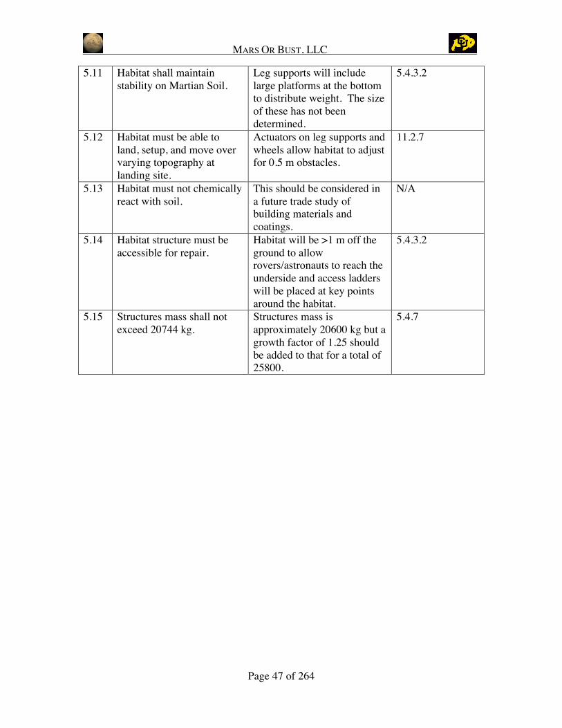
5.11 Habitat shall maintainstability on Martian Soil.
Leg supports will includelarge platforms at the bottomto distribute weight. The sizeof these has not beendetermined.
5.4.3.2
5.12 Habitat must be able toland, setup, and move overvarying topography atlanding site.
Actuators on leg supports andwheels allow habitat to adjustfor 0.5 m obstacles.
11.2.7
5.13 Habitat must not chemicallyreact with soil.
This should be considered ina future trade study ofbuilding materials andcoatings.
N/A
5.14 Habitat structure must beaccessible for repair.
Habitat will be >1 m off theground to allowrovers/astronauts to reach theunderside and access ladderswill be placed at key pointsaround the habitat.
5.4.3.2
5.15 Structures mass shall notexceed 20744 kg.
Structures mass isapproximately 20600 kg but agrowth factor of 1.25 shouldbe added to that for a total of25800.
5.4.7

MARS OR BUST, LLC
Page 48 of 264
6 Electrical Power Distribution and Allocation Subsystem
6.1 Overview
The power subsystem will manage, distribute and store power throughout the Martianhabitat. Both mobile and stationary sources of power will be present within the habitat toprovide power for all the functions of the habitat and mission.
6.1.1 Level 2 Requirements
The following requirements were derived from the DRM and level 1 requirements:Table 6.1: Level 2 Requirements
Requirement Number Requirement Description Source
6.1 Supply sufficient power with 3-level redundancy DRM 1.3.3.7
6.2 Supply power while reactors are being put online DRM 3.6.4.6
6.3 Transfer power from reactor to habitat DRM 3.6.3.7
6.4 Distribute power on a multi-bus system Derived
6.5 Provide storage and interfaces for rovers/EVA suits DRM 3.6.4.6.2
6.6 Interface with transit vehicle power sources Derived
6.7 Regulate voltage to a usable level Derived
6.8 Include a fault protection system Derived
6.9 Provide an emergency power cutoff DRM 3.6.3.7
6.10 Follow maintenance and safety procedures Derived
6.11 Have power dissipation capability Derived
6.12 Be flexible in order to allow for future expansion or addition DRM 2.4.4
6.13 Mass must not exceed 3249 kg (including in-transit power) DRM 3.6.3.4
6.1.2 Power Profile
The power profile shown in Table 6.2 was created by collecting peak power usage fromeach subsystem during various mission modes. These modes include both non-crewedand crewed times as well as a survival mode with battery and non-battery, in case thenuclear reactor is not operational during survival mode. The crewed active day and nightmodes push the limits of the allocated 25 kW to the habitat [Hoffman and Kaplan, 1997].However, these numbers could be reduced with further revisions from each subsystem.Also, the survival modes have relatively high power usage because the crew must be ableto perform an EVA. If the habitat was to go into a survival battery mode, ECLSS wouldnot have the water filtration system on and the habitat would run off the storage tanks.This is why the battery and non-battery power survival values differ.

MARS OR BUST, LLC
Page 49 of 264
Table 6.2: Power Profile
Mission Mode Time in Mode Total (kW)Landing 6.9
Set-up 11.4Survival (battery) 6.1
Survival (Nonbattery)12 hours 6.1Day:
Active 24.9Non-active 9.1
Survival (battery)Time dependent process=> energy balance required 10.4
Survival (Nonbattery)12 hours 12.4Night:
Active 26.9Non-active 11.1
Survival (battery)Time dependent process=> energy balance required 10.4
Survival (Nonbattery)12 hours 12.4
Power Consumed by Habitat During Specific Mode
Non-crew
Crew
Time dependent process => energy balance required
6.1.3 Mass/Power/Volume Breakdown
The mass of electrical cabling inside the habitat can be estimated by assuming differentgauges of wire. Aluminum wire would most likely be used due to its low mass and highconductivity. Below is a table showing several different gauges of wire as well as themass of 5000 m of that gauge.
Table 6.3:Electrical Cabling Mass and Thermal Breakdown
GaugeDiameter
(cm) Area (cm2)Mass(kg/m)
Mass for5000m ofcabling
Resistance(ohms/km
@ 20C)
% Lossfor 25
kW1 0.73 0.42 0.11 572.30 0.68 2.352 0.65 0.34 0.09 453.76 0.86 2.974 0.52 0.21 0.06 285.41 1.36 4.736 0.41 0.13 0.04 179.46 2.16 7.518 0.33 0.08 0.02 112.91 3.32 11.54
10 0.26 0.05 0.01 71.00 5.29 18.3512 0.21 0.03 0.01 44.64 8.40 29.1614 0.16 0.02 0.01 28.10 13.35 46.3616 0.13 0.01 0.00 17.65 21.26 73.8218 0.10 0.01 0.00 11.11 33.79 117.3420 0.08 0.01 0.00 7.00 53.48 185.69
[Power Stream, 2003]
The masses were calculated using simple volume calculations with 2.7 g/cm3 as thedensity of aluminum. Table 6.3 also shows the resistance and resistance losses using atotal of 25 kW. Using this table, the total mass can be estimated for electrical cabling inthe habitat. We chose to use 5000 meters of cabling for an estimate, but the table also hasa mass per unit length for future calculations, as the total cabling becomes more apparent.

MARS OR BUST, LLC
Page 50 of 264
Using the table, we estimated the mass to be around 150 kg and heat losses fromresistance to be around 10%. Any higher losses would be too inefficient and shouldresult in choosing a larger gauge. We also realize that an actual habitat would use acombination of smaller and larger gauges depending on the load.
The mass of the power subsystem was calculated to include all of the equipment thatwould be used in a regulated system. This includes the charge control, batteries,regulation, conditioners, circuit breakers, and wire needed to carry out the full mission ofthe subsystem. Because this is the initial design phase and all of the components are notknown as of yet, the mass of the power system is an estimate dependant upon the poweroutput. The total mass of the power subsystem equipment was estimated using the ratioof 11.4 kg/kW for all equipment less the wiring and batteries [Larson and Pranke, 2000].The mass of a 25 kW system would be 285 kg. The batteries were sized to provide 10kW of power to keep the habitat running until power could be restored or provided fromthe rover. The habitat can be supported by battery power for 24 hours. Using Li-ionbatteries with a specific power of 0.17 kW*h/kg and the specified power needed andtime, a mass of 1411 kg of batteries is needed. A mass of 100 kg was allocated for sparebreakers and other equipment that may need replacing. Table 6.4 summarizes the mass ofthe power subsystem. The estimated volumes are shown as well. The volume for thebatteries was estimated by using the energy density of 160 W*h/L [Larson and Pranke,2000]. The total volume of the power subsystem, including batteries, is 3.6 m3.
Table 6.4: Power System Masses and Volumes
Power System Masses and Volumes
Battery Mass W*h/kg W Time (h) kg Volume (m3)
Li-Ion 170 10000 24 1411.765 1.5
Regulated system mass 11.4 25 285 2
Spares (breakers, etc.) 100 0.10
Total mass w/o wires 1796.765
Total Volume 3.60
The total mass and volume breakdown is shown in
Table 6.5.

MARS OR BUST, LLC
Page 51 of 264
Table 6.5: Mass/Volume Breakdown
Power SubsystemTechnologies
Wires/Cabling
Component #Weight
(kg)
Add.Weight
(kg)
TotalWeight
(kg)Power(kW)
TotalPower(kW)
Volume(m3)
TotalVolume
(m3)
CrewTime
(hrs/day)
Wires/Cabling 150.00 2.5* 0.10
Totals 150 2.5 0.1
*Amount of heat generated
Batteries
Component #Weight
(kg)
Add.Weight
(kg)
TotalWeight
(kg)Power(kW)
TotalPower(kW)
Volume(m3)
TotalVolume
(m3)
CrewTime
(hrs/day)
Li-ion 1411.77 10* 3.00
Totals 1411.77 10 3
*Amount of power produced, not needed
Regulated System
Component #Weight
(kg)
Add.Weight
(kg)
TotalWeight
(kg)Power(kW)
TotalPower(kW)
Volume(m3)
TotalVolume
(m3)
CrewTime
(hrs/day)
Regulated System 285.00 25.00 1.00
Spares (breakers, etc.) 200.00
Totals 485 25 1
Grand Totals 2046.77 37.50 4.10
6.1.4 Input Output
The input/output diagram (Figure 6.1) for the power subsystem is fairly simple. Power istaken in from the nuclear reactor and distributed to the subsystems throughout the habitat.

MARS OR BUST, LLC
Page 52 of 264
Approximately 2.5 kW of heat is output to the thermal subsystem and command is inputfrom the C3 subsystem.
Figure 6.1: Input/Output Diagram
6.2 Design and Assumptions
6.2.1 Assumptions
There were several assumptions made in the design of the power subsystem. Even whilein transit, the habitat requires a minimum amount of power. It was assumed that thispower would be supplied by the launch vehicle before it arrives on Mars. Also, it isassumed that the nuclear reactor would already be on the surface of Mars to provide thehabitat with power along with the cabling used to transfer power from the reactor to thehabitat. The habitat is allocated 25 kW of the maximum 160 kW produced by the nuclearreactor [Hoffman and Kaplan, 1997].
6.2.2 Functional Diagram
The power system will take power from the nuclear reactor and distribute it to thesubsystems. There will be two reactors but only one will be used at a time, the other willserve as a backup [Hoffman and Kaplan, 1997]. The power will flow through a three

MARS OR BUST, LLC
Page 53 of 264
bus, regulated system. Figure 6.2 below is a diagram of the power flow. The system willallow for power to flow from the reactors to the conditioner and regulator or to thebatteries via a charge controller if the batteries are in need of charging. Power can alsoflow from the batteries to the conditioner and regulator if the reactors are offline. Afterpower is regulated to a usable voltage, it is transferred on either of three buses to thedistribution hub. Due to the life critical nature of the power subsystem, it was designedwith three-level redundancy via a three bus architecture. From here the power istransferred to separate breakers that are specified for each subsystem with an extrabreaker for life or mission critical systems that cannot be turned off. Figure 6.3 shows, asan example, the critical components of the Command, Control, and Communicationunder the life/mission critical breaker. Most ECLSS functions are considered life ormission critical and therefore kept under the ECLSS breaker. Under each subsystem,there can also be branches to each component or a breaker to a few componentsdepending on the need of the component. Figure 6.4 and Figure 6.5 show examples ofthe power flows within the ECLSS and C3 subsystems. The system uses circuit breakersto allow for equipment to be powered down while connecting or disconnecting theequipment, reducing the risk of arching. The system is designed to minimize theinterference between subsystems while components within a certain system are beingconnected or disconnected components. These figures show a basic structure for thelayout of the power grid, however since all components are not known at this point in thedesign, a complete system cannot be mapped out.
Figure 6.2: General Functional Diagram
Figure 6.3: Life/Mission Critical

MARS OR BUST, LLC
Page 54 of 264
Figure 6.4: ECLSS
Figure 6.5: C3
6.2.3 Alternating Current vs. Direct Current/120V

MARS OR BUST, LLC
Page 55 of 264
The nuclear reactor will be outputting AC power, which is easier to transport at highvoltages over long distances. Based on requirements of today’s technology, it wasdecided to use a voltage regulator and operate the habitat on 120 V. Also, this is a safeoperating voltage because there is little plasma interaction, which will reduce the risk ofarcing. Since the habitat will be operating at 120 V and the reactor is 2 km away, ACcurrent is ideal [Hoffman and Kaplan, 1997]. However, the habitat will be using DCpower, so the input current from the reactor will need to be converted.
6.2.4 Contingency Power Supply
The power system, being life-critical, needs two backups. There are two nuclear reactorson the surface of Mars, of which only one will provide power at any given time. Thesecond reactor is on standby as the first backup. The second backup is the 10 kW powersupply in the pressurized rover. This supply can be connected to the habitat and used topower critical systems. The batteries in the habitat will remain charged; capable ofproviding 10 kW of power for 24 continuous hours while the second reactor is broughtonline. If needed, a rover could return from a mission and connect to the habitat to supplypower. The batteries will insure that the habitat is never without power during thetransition from one source to another.
Battery life depends on the number of charge/discharge cycles. After 500 cycles, thebatteries will still provide 10 kW, which is sufficient to power the habitat and keep theoccupants alive in the emergency mode, but may not be enough to sustain all missionactivities. Therefore, when in the emergency mode, only life and mission critical systemswill be powered.
6.2.5 Mission Operations Overview
The power subsystem will require some operations during the mission. In case ofemergency, the power cutoff and restart was estimated to take 2 hours and require 3crewmembers. Safety concerns include arcing and potential damage to equipment.General power maintenance, such as replacing fuses or resetting circuit breakers, wouldonly take 20 minutes to perform with 2 crewmembers. Maintenance will occur asneeded, with only general electrical safety concerns. Manual switching of lights,computers, etc. will require one crewmember and occur as needed. When the equipmentis brought on-line or the power is cycled, the initial power-up and breaker switching willtake 2 hours with 2 crewmembers. There is potential for arcing and damage toequipment. This operation will occur at the initial habitat set up and wheneveremergency power cutoff and restart occurs. The majority of the equipment will haveautomated switching, occurring as needed.
6.3 Verification of Requirements
6.3.1 Level 2 Requirements

MARS OR BUST, LLC
Page 56 of 264
The power group was as able to design the subsystem to meet all level 2 requirements.Table 6.6 shows the level 2 requirements and the methods used to meet them. The 3-level redundancy was met with a back up reactor and solar panels. Batteries were alsoimplemented for redundancy. The design mass is 2050 kg, which is well below the 3250kg allocation recommended by the DRM [Hoffman and Kaplan, 1997].
Table 6.6: Requirements Verification
# Requirement Description DesignReport
Sec.6.1 Supply sufficient power with 3-level redundancyBack up reactor, solar panels, batteries, and
pressurized rover power supply5.2.2 5.2.4
6.2 Supply power while reactors are being put online Batteries 5.2.4
6.3 Transfer power from reactor to habitat Cabling 5.1.36.4 Distribute power on a multi-bus system Multi-bus system 5.2.26.5 Provide storage and interfaces for rovers/EVA
suits Batteries, connectors 5.2.46.6 Interface with transit vehicle power sources Connectors 5.1.36.7 Regulate voltage to a usable level Voltage regulator 5.2.36.8 Include a fault protection system Circuit breakers 5.2.26.9 Provide an emergency power cutoff Emergency power cutoff 5.2.26.10 Follow maintenance and safety procedures Mission operations 5.2.56.11 Have power dissipation capability Regulation 5.2.26.12 Be flexible in order to allow for future
expansion or addition Designed flexibility in layout 5.2.26.13 Mass must not exceed 3249 kg (including in-
transit power)mass = 2050 kg 5.1.3
6.3.2 Failure Mode Effects Analysis
There are potentially two failures that can occur in the power subsystem. The first is apower outage, which can result from a power outage to the whole habitat or to specificsubsystems. As can be seen from Figure 6.6, a power outage to a subsystem can resultfrom many different causes, including damaged power lines, a damaged transformer or adamaged connector. In these cases, the crew must fix or replace the specific technologythat had been damaged. However, during this time, the backup power may need to beused. Whether the backup power from the power subsystem or the battery located at eachsubsystem will be used is determined by the technology that had been damaged. Forexample, if the power line to a subsystem is damaged, backup power for life-criticalcomponents within that subsystem will be drawn from a battery located within thatsubsystem.
Power outage to the whole habitat can occur when the reactor or the transformer isdamaged. Depending on the required repair time, it may be necessary to use both thebatteries and solar panels to power the habitat during day and night. The rovers may alsoprovide a second backup power supply.
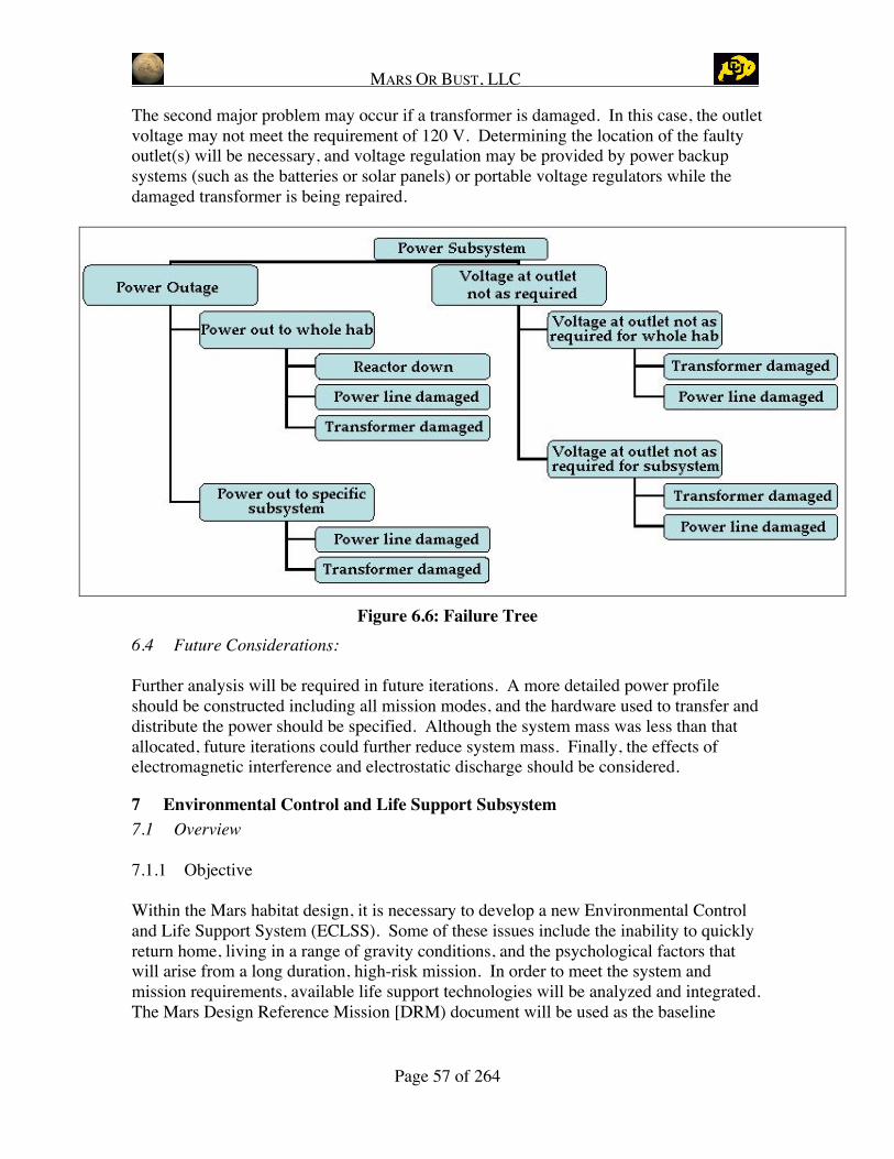
MARS OR BUST, LLC
Page 57 of 264
The second major problem may occur if a transformer is damaged. In this case, the outletvoltage may not meet the requirement of 120 V. Determining the location of the faultyoutlet(s) will be necessary, and voltage regulation may be provided by power backupsystems (such as the batteries or solar panels) or portable voltage regulators while thedamaged transformer is being repaired.
Figure 6.6: Failure Tree6.4 Future Considerations:
Further analysis will be required in future iterations. A more detailed power profileshould be constructed including all mission modes, and the hardware used to transfer anddistribute the power should be specified. Although the system mass was less than thatallocated, future iterations could further reduce system mass. Finally, the effects ofelectromagnetic interference and electrostatic discharge should be considered.
7 Environmental Control and Life Support Subsystem7.1 Overview
7.1.1 Objective
Within the Mars habitat design, it is necessary to develop a new Environmental Controland Life Support System (ECLSS). Some of these issues include the inability to quicklyreturn home, living in a range of gravity conditions, and the psychological factors thatwill arise from a long duration, high-risk mission. In order to meet the system andmission requirements, available life support technologies will be analyzed and integrated.The Mars Design Reference Mission [DRM) document will be used as the baseline

MARS OR BUST, LLC
Page 58 of 264
mission and an approach will be developed to provide a comprehensive life supportsystem that will optimally satisfy the needs of the Mars DRM.
7.1.2 Class Specific Scope
The scope of this project is to research relevant technologies and determine an integratedsystem that will successfully accomplish the above-mentioned objective. This section ofthe project was completed over the course of the Fall 2002 semester for 3 credit hours.There were two reports from two different teams that were used to find the optimaldesign for the ECLSS subsystem.
7.1.3 System Design Philosophy
The ECLSS subsystem is separated into four subsystems: Atmosphere, Water, Waste, andFood. The four subsystems are then integrated into one functional system. Figure 7.1shows the subsystem interactions with the human in the loop. All subsystems interactwith one another on different levels. All subsystem interactions are taken into accountand an iterative system design is implemented to maximize efficiency. The final ECLSSsubsystem is based off the optimum individual subsystems that interact best with theother subsystems while maintaining a high overall system performance. Individualsubsystem requirements and assumptions will be analyzed while taking into account theoverall system requirements and assumptions previously laid out. An iterative design ofthe overall system and its subsystems is completed to determine the optimal way ofmeeting all requirements.
Because of time limits on this project, it was decided that the most important productshould be a workable system. Trade studies were not considered a priority and as a resultthe system that was chosen was a combination of two papers that were final reports in aprevious class, Advanced Life Support Systems, ASEN 5116. These were Shidemantleet al., 2002, and Kungsakawin et al., 2002. The base design components for the food,waste, and atmosphere subsystem came directly from Shidemantle’s report while thewater subsystem came from Kungsakawin’s report. The full references for these papersare included at the end of this report.

MARS OR BUST, LLC
Page 59 of 264
Figure 7.1: Subsystem Interactions
7.2 Requirements
As mentioned earlier, The Environmental Control and Life Support subsystem (ECLSS)is responsible for providing a physiologically and psychologically acceptableenvironment for humans to survive and maintain health in the Mars habitat. This includesproviding and managing food, water, waste, and atmospheric conditions, as well assupplying crew accommodations and medical services. To determine how to providewhat is necessary requirements must be determined. Top-level requirements, which arealso known as level 1 requirements, are requirements that are stated in the DRM. Fromthose, assumptions and level 2 requirements can be derived. Top Level requirements andlevel 2 requirements for the ECLSS subsystem are given below.
Top Level Requirements• Provide life support functions for a crew of 6• 180 worst-case transit time between Earth and Mars• 600 day worst-case surface stay on Mars• Perform the entire mission assuming no resupply from Earth• Take advantage of ISRU when possible• Operate during launch, transit, descent, and surface g-loads• Provide 2 levels of backup (life critical)• Do not rely on biological systems for life support functions• Provide as much loop closure as possible• Reliability, maintainability, and safety
Derived Requirements and Assumptions• Shall provide adequate atmosphere, gas composition, and pressure control.• Must have necessary Gas Storage for mission duration.• Must have adequate Ventilation.
FOOD
WATERAIR
WASTE

MARS OR BUST, LLC
Page 60 of 264
• Must provide Trace Contaminant Control.• Shall provide Temperature and Humidity Control.• Must have Fire Detection and Suppression.• Must supply entire crew with adequate sources and amounts of food and potable
water for a 4-6 month transit to Mars, and 600-day stay on the surface ofMars.
• Shall be able to collect and store liquid, solid, and concentrated wastes forimmediate and/or delayed resource recovery.
• Must provide adequate supply of hygiene water.• Shall provide psychological support by taking into account crew environment
and other human factors.• Shall monitor and report radiation levels in habitat to other subsystems.• Mass must not exceed 4661 kg.• Target life support system power usage of 12.1 kW• Must allow for crew input to habitat temperature and humidity levels.
7.3 Atmosphere Subsystem
The purpose of an atmosphere management subsystem is to maintain an acceptableatmosphere for human life. For a Mission to Mars, analysis of the system levelrequirements revealed that the subsystem would operate in 1/3 gravity. This exercise willpush the current limits in knowledge about long-term reliability and functionality. Thefollowing evaluation accounts for these system level concerns in the design approach andin the discussion of subsystem level integration results.
7.3.1 Responsibility and Assumptions
An acceptable atmosphere for human life on a Mars mission consists of providing a safeenvironment that meets the physiological and psychological needs of the crew. Thisgeneral requirement translates into subsystem process tasks. These tasks are oxygenprovision, pressure regulation, thermal control, trace contaminant control, carbon dioxidecontrol, and fire detection and suppression. For most of these tasks, the selectedtechnologies must provide the basic functionality while maintaining the key parameter(s)within a specific range of values.
The ecosystem of the Earth incorporates most of the tasks in the regulation of theatmosphere as a whole and in specific areas. On a large scale, the atmosphere providesoxygen (~3.1 psia ppO2) to humans, removes metabolic byproducts (trace contaminantsand carbon dioxide), and maintains a buffer that regulates temperature, pressure andrelative humidity with physical/chemical and biological processes. However, withchanges in latitude, longitude, and altitude there are can be distinct changes intemperature, total and partial pressures, and relative humidity.
In an enclosed environment, these same tasks operate with a smaller buffer size;however, the same basic requirements still need to be met. For the first task, oxygen

MARS OR BUST, LLC
Page 61 of 264
needs to meet the base metabolic oxygen demand of 1 kg O2/person/day along with lossesdue to oxidative technology demands. The ECLSS subsystem is also responsible forsupplying the EVA subsystem with all the life support needs. Considering all theleakages and EVA needs, the cabin still has to maintain a 3.1 psia ppO2, with anacceptable range of 2.83 to 3.35 psia ppO2. The total pressure is regulated to 10.2 psiadue to the frequency of EVA scheduled to the crew. The combination of oxygen andnitrogen results in variations of the total pressure is possible. The thermal control systemmaintains relative humidity between 25%-70% and temperature between 18.3oC –26.7oC. Carbon dioxide removal needs to offset the metabolic production rate of 0.85 kgCO2/person/day in addition to technology products that interact with the crew cabinatmosphere. Humans, material off-gassing, and technologies generate a variety of organicand inorganic compounds (ammonia, nitric oxide, methane, ethylene, and benzene) involatile state or adsorbed to particulates that need to be controlled below the long termSpacecraft Maximum Allowable Concentrations (SMAC), which are 7 mg/m3, 0.9mg/m3, 3800 mg/m3, 340 mg/m3, and 0.2 mg/m3, respectively. Finally, on Earth fires areeventually self-limiting, but in an enclosed environment, the final task of fire detectionand suppression needs to operate quickly and reliably to avoid both direct (life and limb)and indirect (oxygen consumption) hazards [Eckart, 1996].
7.3.2 Design Approach
The evaluation of the atmosphere subsystem entailed a multi-tiered approach. Thisapproach iteratively examined requirements, key mass drivers, and the functionality andintegration of different technologies. The air subsystem requirements were driven by thetop-level requirements and derived from known and assumed technology specific data.The key mass drivers were identified in the baseline mission scenario, which consisted ofonly existing (and allowable) non-regenerable technologies. These mass drivers werethen initially examined to minimize consumables. After gathering information andranking current technologies, a functional subsystem was created and then iterativelychanged to maximize the reuse or recycle of materials to reduce mass losses while stillconforming with the top level and subsystem level requirements.
7.3.3 Technologies and Trade Study
To understand the key mass drivers and interactions, a baseline system with existing non-regenerable technologies used on Space Shuttle, ISS, and MIR was created. The basicsystem details and interactions are shown in Table 7.1 and Figure 7.2.
The key mass drivers for the baseline system were the carbon dioxide removal (46%),oxygen provision (38%), and total pressure regulation (13%) systems. These identifiedsystems are all high in consumable mass. As a first cut for mass savings, the oxygen,nitrogen and carbon dioxide system variables are reviewed to determine options for theminimization of consumables. The consumable mass for the carbon dioxide removalsystem is due to the LiOH canisters, which translates into mass savings dependentcompletely upon the selected carbon dioxide removal or reduction technology. The mass
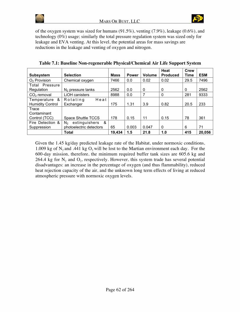
MARS OR BUST, LLC
Page 62 of 264
of the oxygen system was sized for humans (91.5%), venting (7.9%), leakage (0.6%), andtechnology (0%) usage; similarly the total pressure regulation system was sized only forleakage and EVA venting. At this level, the potential areas for mass savings arereductions in the leakage and venting of oxygen and nitrogen.
Table 7.1: Baseline Non-regenerable Physical/Chemical Air Life Support System
Subsystem Selection Mass Power VolumeHeatProduced
CrewTime ESM
O2 Provision Chemical oxygen 7466 0.0 0.02 0.02 29.5 7496Total PressureRegulation N2 pressure tanks 2562 0.0 0 0 0 2562CO2 removal LiOH canisters 8988 0.0 7 0 281 9333Temperature &Humidity Control
R o t a t i n g H e a tExchanger 175 1.31 3.9 0.82 20.5 233
TraceContaminantControl (TCC) Space Shuttle TCCS 178 0.15 11 0.15 78 361Fire Detection &Suppression
N2 extinguishers &photoelectric detectors 65 0.003 0.047 0 6 71Total 19,434 1.5 21.8 1.0 415 20,056
Given the 1.45 kg/day predicted leakage rate of the Habitat, under normoxic conditions,1.009 kg of N2 and .441 kg O2 will be lost to the Martian environment each day. For the600-day mission, therefore, the minimum required buffer tank sizes are 605.6 kg and264.4 kg for N2 and O2, respectively. However, this system trade has several potentialdisadvantages: an increase in the percentage of oxygen (and thus flammability), reducedheat rejection capacity of the air, and the unknown long term effects of living at reducedatmospheric pressure with normoxic oxygen levels.

MARS OR BUST, LLC
Page 63 of 264
Figure 7.2: Baseline non-regenerable physical/chemical air ECLSS schematic
This schematic illustrates the basic subsystem level intra-and interactions for the airmanagement system.
The remaining mass savings in this system are based on the selection of individualcandidate technologies and maximization of recyclables for compatible subsystem andsystem level interactions. Initially, information on a variety of technologies for meetingthe different tasks was compiled into spec sheets. These technologies were then sized ina similar fashion to the baseline system calculations to meet the associated task. In thecase of missing information for a specific technology, some assumptions were made.After the technologies were reasonably detailed, the technologies were ranked basedupon their equivalent system mass in Table 7.2.
crew cabinchemicalLiO2
cabinleakage N2 , O2 , H2O
O2
N2 storagetanks
LiOH
N2
FDS
To: hygiene water tank
H2O
T&Hcontrol
To: trash compactor
TCCS
To: trash To: trash compactor

MARS OR BUST, LLC
Page 64 of 264
Table 7.2: Air Management Life Support Technology RankingsTechnologies TRL ESM RANKOxygenSPWE (w/ EDC) 9 2119 1SPWE (w/ Sabatier) 9 4394 2SPWE (w/o Sabatier) 9 5515 3Tank- cryogenic 9 6573 4O2 chemical (TRK) 9 7496 5Tank- pres vessel 9 7681 6Total Press Reg (Nitrogen)Tank- cryogenic 9 2224 1Tank- pres vessel 9 2562 2Carbon Dioxide Removal or ReductionEDC 6 162 1SAWD 6 190 24BMS (CDRA) 8 418 3Sabatier (CDReA w/ H2 tanks) 9 450 4Bosch 6 885 5LiOH 9 9333 6Thermal and Humidity ControlCHX-rotating 6 267 1TCCDetectionGC/MS 9 150 1TreatmentTCCA 9 135 1TCCS 9 201 2Activated Charcoal 9 In TCCS & TCCACatalytic Oxidation 9 In TCCS & TCCA
Particulate Filters 9 In TCCS & TCCAFDSDetectionISS Photoelectric 9 21 1STS Ionization 9 21 2SuppressionNitrogen Agent 9 68 1Halon 1301 Agent 9 68 2CO2 9 85 3Depressurization 9 694 4
Note: ESM = mass + 0.0115 kg/kW (power) + 9 kg/m3 (volume) + 0.0069 kg/kW (heatrejection) + 1 kg/crew-hour (crew time) + 5% kg total surcharge/TRL less than 9.
The highest ranked systems were subsequently analyzed and deemed compatible.However, further analysis was required to determine the potential recyclables betweenthe selected oxygen generation system (solid polymer water electrolysis, or SPWE) andthe carbon dioxide reduction/removal systems (Sabatier, Bosch, and electrochemicaldepolarized concentrator). For the primary option A (Figure 7.3), there is a high degree of

MARS OR BUST, LLC
Page 65 of 264
water return from the EDC to the SPWE, which reduces the additional water supplyrequired to produce oxygen from 5250 kg H2O to 1,854 kg H2O, see Table 7.3. Option B(Figure 7.4) has a lower degree of water return from the Sabatier reactor which onlyreduces the additional water supply required to produce oxygen from 5,250 kg H2O to4,129 kg H2O, see Table 7.4. Based on these tradeoffs along with the fixed massdifferences, the option A saves 2,500 kg of mass over option B and 14,000 kg of massover the baseline scenario.
Table 7.3: Physical/Chemical Air Life Support System for Mars Mission–Option A
Subsystem Selection Mass Power VolumeHeatProduced
CrewTime TRL ESM
O2 Provision SPWE 2096 1.84 2.24 1.84 2 9 2119Total PressureRegulation
N2 p r e s s u r etanks 2562 0 0 0.00 0 9 2562
CO2 removal EDC 133 0.30 0.2 0.67 5.4 6 162Temperature &Humidity Control
Rotating HeatExchanger 175 1.31 3.9 0.82 20.5 6 267
TraceContaminantControl (TCC) GC/MS,TCCA 273 0.08 0.9 0.18 4 9 286
Fire Detection &Suppression
N2 extinguishers& photoelectricdetectors 80 0.003 0.3 0.00 6 9 88Total 5319 3.53 7.5 3.51 37.9 5485
Notes:1) Acronyms: SPWE: solid polymer water electrolysis, EDC: electrochemical
depolarized concentrator, GC/MS: gas chromatography/mass spectrometer,TCCA: trace contaminant control system (catalytic oxidation, activated carbon, &particulate filters)
2) SPWE mass includes the consumable water supply
Table 7.4: Physical/Chemical Air Life Support System for Mars Mission–Option B
Subsystem Selection Mass Power VolumeHeatProduced
CrewTime TRL ESM
O2 Provision SPWE 4371 1.84 2.24 1.84 2 9 4394Total PressureRegulation
N2 pressuretanks 2562 0 0 0.00 0 9 2562
CO2
removal/reductionSabatier w/ H2
Tanks 389 0.0006 0.3 0.0029 35 9 450Temperature &Humidity Control
Rotating HeatExchanger 175 1.31 3.9 0.82 20.5 6 267
TraceContaminantControl (TCC) GC/MS,TCCA 273 0.08 0.9 0.18 4 9 286
Fire Detection &Suppression
N2 extinguishers& photoelectricdetectors 80 0.003 0.3 0.00 6 9 88Total 7850 3.2 10.1 2.8 67 8048

MARS OR BUST, LLC
Page 66 of 264
Figure 7.3: Physical/Chemical Air Life Support System Schematic – Option A
crew cabin
cabinleakage N2 , O2 , H2O
O2
N2 storagetanks
EDC*2
N2
FDS
To: hygiene water tank
T&Hcontrol H2O
To: vent To: trash compactor
SPWE
H2
TCCA
To: vent
H2 , O2
CO2
From: H2O tank
H2O

MARS OR BUST, LLC
Page 67 of 264
Figure 7.4: Physical/Chemical Air Life Support System Schematic – Option B
7.3.4 Design
The subsystem generally operates autonomously to control process functions andair/water flow rates with optional crew control of the temperature set point. Since OptionA was selected, the processes and its functionality are detailed in Figure 7.3 and Table7.3 and represent the unsupplemented operational state of the subsystem on Mars.
On Mars, a tertiary option may be utilized in case of a partial or full failure of the fuelgeneration system (ISRU) due to filter clogging. This option would entail the direction ofthe excess H2 and CO2 from atmospheric subsystem to the ISRU unit by a sealed source.Specifically, there are nine nitrogen tanks for the mission, and one tank will be emptyupon landing with a second tank available in 30 days after arrival. These tanks could beretrofitted to capture the H2 and CO2 and secure them for use by the ISRU system.
crew cabin
cabinleakage
O2
N2 & H2storagetanks
SB *10
N2
FDS
To: hygiene water tank
H2O
To: vent To: trash compactor
SPWE TCCA
H2
CH4
From: H2O tank
H2O
H2
N2 , O2, H2O
H2O
T&Hcontrol

MARS OR BUST, LLC
Page 68 of 264
The analysis of the atmosphere subsystem intra- and interactions proved integralinformation to the determination of the optimal system. In the baseline system design, thekey mass drivers were the carbon dioxide removal, oxygen provision, and total pressureregulation systems. With the addition of alternative physical/chemical technologies, thekey mass drivers shifted to oxygen and nitrogen provision system due to leakage andEVA losses.
The values for heat, power, and volume for the completed atmosphere system are locatedbelow in Table 7.5.
Table 7.5: Heat, Power, and Volume for ECLSS atmosphere technologies
Atmosphere System
Component
HeatGenerated
(kW)Power(kW)
Volume(m^3) Mass (kg)
Solid Polymer Water Electrolysis (SPWE) 1.8400 1.840 2.240 2096.00
Electrochemical Depolarized Concentrator (EDC) 0.6700 0.300 0.200 133.00
Rotating Heat Exchanger 0.8200 1.310 3.900 175.00
Gas Chromatography/Mass Spectrometer (GC/MS)Trace Contaminant Control System (TCC) 0.1800 0.080 0.900 273.00
Fire Detection System 0.0030 0.003 0.300 80.00
N2 Pressure tanks 0.0000 0.000 0.000 2562.00
Plumbing (10% of total) n/a n/a 7.540 275.70
Spares 0.3513 0.35 1.51 303.27
Total 3.8643 3.8863 16.5880 5897.97
7.4 Water Subsystem
The baseline water management requirements are to provide potable and hygiene water tothe crew for the duration of the mission. As outlined in the human mass balance section,3.905 kg/6 person crew/day of potable water and 23.65 kg/6 person crew/day of hygienewater must be provided and meet the water quality requirements.
7.4.1 Responsibility and Assumptions
The requirements for water management are defined in Table 7.6. All the water that thecrews will receive has to meet the following requirement for the purpose of maintainingthe health of the crews. Water will be tested using the monitoring technologies that willbe discussed later in the Water subsystem. If the water does not meet the standards, it willbe sent back for future processing.

MARS OR BUST, LLC
Page 69 of 264
Table 7.6: Water Quality Requirement: Maximum Contaminant LevelsQuality Parameters Potable HygienePhysical ParameterTotal Solids (mg/l) 100 500Color, True (Pt/Co units) 15 15Taste (TTN) 3 N/AOdor (TON) 3 3Particulates (max size - µm) 40 40pH 6.0-8.5 5.0-8.5Turbidity (NTU) 1 1Dissolved Gas (free @ 37 °C No Detectable Gas N/AFree Gas (@ STP) No Detectable Gas No Detectable GasInorganic Constituents (mg/l)Ammonia 0.5 0.5Arsenic 0.01 0.01Barium 1.0 1.0Cadmium 0.005 0.005Calcium 30 30Chlorine (total - include chloride) 200 200Chromium 0.05 0.05Copper 1.0 1.0Iodine (total - include organic iodine) 15 15Iron 0.3 0.3Lead 0.05 0.05Magnesium 50 50Manganese 0.05 0.05Mercury 0.002 0.002Nickel 0.05 0.05Nitrate (NO3-N) 10 10Potassium 340 340Selenium 0.01 0.01Silver 0.05 0.05Sulfate 250 250Sulfide 0.05 0.05Zinc 5.0 5.0Bactericide (mg/l)Residual Iodine (minimum) 0.5 0.5Residual Iodine (maximum) 4.0 6.0Aesthetics (mg/l)Cations 30 N/AAnions 30 N/ACO2 15 N/AMicobialBacteria (CFU/100ml)Total Count 1 1Anaerobes 1 1Coliform 1 1Virus (PFU/100 ml) 1 1Yeast & Mold (CFU/ 100ml) 1 1Organic Parameters (ug/l)Total Acids 500 500Cyanide 200 200Halogenated Hydrocarbons 10 10

MARS OR BUST, LLC
Page 70 of 264
Quality Parameters Potable HygieneTotal Phenols 1 1Total Alcohols 500 500Total Organic Carbon (TOC) 500 10,000Uncharacterized TOC (UTOC) 100 1,000
7.4.2 Design Approach
The first step in the design process involves calculating a baseline system. The baselinesystem is simple. All the water will be lifted and carried for the entire mission duration.However, this accounts for a mass of nearly 99,198 kg of water. Closing the water loopby recycling urine, hygiene water, and atmospheric condensate will make very significantmass savings. Candidate technologies were then identified to close the loop and wereranked taking into account TRL, mass, power, volume, efficiency, and hazard level.Winning technologies were then integrated into the water subsystem.
7.4.3 Technologies and Trade Study
The baseline architecture is simple. The water comes from the storage and all the waterwas taken with the crew.
Figure 7.5: Open Loop Diagram w/Flow Rates in kg/day for 6 crewmembers
Table 7.7: Water Management ParametersMass (kg) Power (kW) Volume (m3)
600 Days 99198.0 0.02 99.24
Figure 7.5 shows the baseline system block diagram for the water managementsubsystem. The only components needed to operate the system include storage anddelivery. The storage mass was assumed to be 20% of the stored mass.
Potable
Laundry
Hygiene
18.216
9.4
2.5
Food at CrewAccommodation
0 .214
To Waste Management
WaterStorage

MARS OR BUST, LLC
Page 71 of 264
Water processing technologies were broken down into two main categories, Potable andHygiene processing and urine processing since urine needs more treatment than hygienewater. Table 7.8 shows the candidate technologies considered for the potable andhygiene water processing.
Table 7.8: Hygiene & Potable Water Treatment Candidate TechnologiesWM Function Candidate TechnologiesHygiene & Potable WaterTreatment
• MIR Technology (Condensate)• Reverse Osmosis (RO)• Multifiltration (MF)• Electrodialysis• Oil and Water Seperation
• Rock/Plant/Microbial Filtering System• Thermoelectric Integrated Membrane
Evaporation (TIMES)• Granular Activated Carbon (GAC)• Aqueous Phase Catalytic Oxidation Subsystem
(APCOS)• Ultrafiltrtion• MilliQ Absorbtion Beds• Pasteurization• Ionic Silver• Regenerable Microbial Check Valve (Iodine)• UV-visible Spectrophotometer (laser)
Due to the significant list of candidate technologies, a series of selection criteria neededto be used to rule out undeveloped technologies. TRL levels less than 6 and completelack of information were the primary criteria used to reduce the number of candidatetechnologies. Further elimination of technologies was performed during the formation ofthe spec sheets due to key information (such as mass or power) missing.
The potable and hygiene water processing consisted of numerous technologies, eachconsisting of unique pre and post treatment processes. This required the development ofsystems of different technologies to be traded between. Hygiene and potable water willbe processed with the same system. Consumable data is primarily described for completeprocessing to potable quality water, therefore the data is not available for a uniquehygiene water processing trade. The following systems were traded:
-UltraFiltration/Reverse Osmosis + APCOS-UltraFiltration/Reverse Osmosis + MilliQ Absorbtion Beds-Multifiltration

MARS OR BUST, LLC
Page 72 of 264
The UF/RO and MilliQ Absorption Beds won the trade. Multifiltration’s downside wasits large consumable mass while the APCOS was significantly penalized due to theunknown oxygen consumption for the oxidation process.
Microbial control was separated from this trade study due to its need in any systemchosen. Due to lack of information, the Iodine Microbial Check Valve was chosen. Iodineremoval beds are also required before potable use to eliminate long-term effects of Iodineconsumption.
Urine processing is separated from hygiene water processing due to its complexity. Table7.9 shows the candidate technologies for urine processing.
Table 7.9: Urine Treatment Candidate TechnologiesWater Management Function Candidate TechnologiesUrine Treatment • MIR Technology (evaporation, steam condensation, sorption,
electrolysis)• Vapor Compression Distillation (VCD)• Vapor Phase Catalytic Ammonia Removal (VAPCAR)• Air Evaporation (AES)• Aqueous Phase Catalytic Oxidation Post-Treatment System
(APCOS)• Super Critical Water or Wet Oxidation (SCWO)• Incineration (oxidation)• Pyrolysis• Aerobic Slurry• Aerobic Solid Processing (composting)• Anerobic Solid Processing• Aquaculture (fish) • Electrochemical Oxidation
Again this large list of technologies was reduced through a few selection criteria. Theprimary selection factor in urine treatment was the elimination of biological systemsfollowing the DRM requirements. TRL levels below 6 and lack of information rules outmany of the other candidates.
Due to the severe elimination of technologies by initial selection criteria, only two wereleft. The urine distillation trade was performed between the following technologies:
-Air Evaporation System (AES)-Vapor Compression Distillation (VCD)
Vapor Compression Distillation won the trade study with the Air Evaporation System insecond. The primary reason the AES places second was due to the high powerconsumption of 1 kW. This is approximately 10% of the allotted power for the spacecraftdedicated to one system. A simple trade between carrying makeup water in the VCD onlysystem versus using an AES to process the brine water on a low duty cycle resulted in asignificant mass savings of approximately 175 kg as well as providing a very simpleredundant system in the case of a VCD failure.

MARS OR BUST, LLC
Page 73 of 264
Figure 7.6: Closed Loop Water Management Flow Diagram
Figure 7.6 shows the integration of the water management subsystem components. Theurine treated by the VCD must be pretreated with Oxone (a commercial oxidizer) andsulfuric acid to prevent the release of ammonia during the distillation process. Brinewater from the reverse osmosis filter is also passed through the VCD to reclaim morewater. The water flow through the VCD can be arranged in numerous forms and is notcompletely shown on this diagram. Brine water from the VCD can be passed backthrough itself to maximize the solid concentration of the brine. The remaining brine wateris stored and periodically processed by the AES. Current AES testing shows a slightlyreduced quality of water from the AES, so this water is reprocessed through the VCD toensure complete processing of the urine. Product water from the VCD is combined withthe remaining wastewater from the craft including that from hygiene. The water streamthen flows through an Ultra filtration unit, which consists of mechanical filtration media.This increases the lifetime and efficiency of the following reverse osmosis filter. Asstated earlier, the brine water produced in processed through the VCD. The product waterthen flows through the Milli-Q absorption bed, which consists of activated carbon and aproprietary organic carbon scavenger media to reduce the TOC to acceptable potablewater quality standards. At this time, Iodine is then added to the water stream formicrobial control. Monitoring then checks the PH, conductivity, TOC and Iodine levelsbefore the water is stored. Hygiene water is used directly from this source. Potable watermust first be passed through the iodine removal bed to reduce the iodine level toacceptable amounts. Online iodine monitoring then ensures this level.

MARS OR BUST, LLC
Page 74 of 264
Water Monitoring is a major subsystem within the water management. Therefore, anytechnology that has the Technology Readiness Level (TRL) of less than 7 is assumed tobe unacceptable for life critical component and not studied in this section. The TRL of 7indicates that the system prototype has been demonstrated in a space environment.However, if the technology is not gravity dependent, the acceptable TRL is said to be 5.At this TRL level, the component and/or the breadboard have been validated in relevantenvironment and shows promising evidences that it would also work in space. With thisin mind, the first tread study would be to do the simple pass/fail elimination due to theTRL level.
Table 7.10: List of Technologies & Associated TRLsTechnologies TRL
Fiber Optic Sensor for Water (for turbidity, color, pH, iodine, metals, ions, NOC, VOC, semi-volatiles and hardness level)
4
Electronic Nose (for taste, metals, NOC and odor) 6Ion Mobility Spectrometry (IMS) (monitor iodine level) 2-4Ion Specific Electrodes (ISE) (for conductivity level) 2-8Capillary Electrophoresis (CE) (for metals level) 3-4Liquid Chromatography (LC) (for metals, ions level) 2-3Ion Coupled Plasma (ICP) (for metals, ions and silver) 3Solid Phase Extraction-Mass Spectrometry (SPE-MS) (for NOC, VOC and semi-volatiles) 2-4Supercritical Fluid Chromatography (SFC) (for NOC, VOC and semi-volatiles) 1-2Liquid Chromatography-Mass Spectrometry (LC-MS) (for NOC, VOC and semi-volatiles) 3Fourier Transform Infrared (FTIR) (for NOC, VOC and semi-volatiles) 4Total Organic Carbon-Infrared (TOC-IR) (for TOC/COD) 4Total Organic Carbon (TOC) - conductivity 6Total Organic Carbon (TOC) - reagentless 2Total Organic Carbon Analyzer 3Gas Chromatography (GC) (for NOC and semi-colatiles) 4Voltametry (for metals and silver) 3UV-visible Spectrophotometer (laser) (for turbidity, color, pH, iodine, metals, ions, NOC,VOC, semi-volatiles and hardness level)
2
Surface Acoustic Wave (SAW) Detector 4Test Kits (for pH, chem-strips for specific compounds) 9Conductivity 8-9Test Kits (for pH, chem-strips for specific compounds) 5-9
Therefore, the technologies that will be studied are the following. TRLs were found athttp://research.hq.nasa.gov.
1. Electronic Nose (for taste, metals, NOC and odor) [TRL 6]

MARS OR BUST, LLC
Page 75 of 264
Figure 7.7: Electronic Nose Equipment
2. Ion Specific Electrodes (ISE) (for conductivity level) [TRL 2-8]
Figure 7.8: Ion Specific Electrode
3. Total Organic Carbon (TOC) – conductivity [TRL 6]

MARS OR BUST, LLC
Page 76 of 264
Figure 7.9: Total Organic Carbon - Conductivity Diagram
Figure 7.10: Actual Total Organic Carbon Device
4. Conductivity [TRL 8-9]
Figure 7.11: Sample of Conductivity Device
5. Test Kits (for pH, chem-strips for specific compounds) [TRL 5-9]
Figure 7.12: Sample Test Kits

MARS OR BUST, LLC
Page 77 of 264
Table 7.11: Water Sample Requirement for Off-Line Monitoring (Initial On-OrbitOperations)
Location Sample Volume FrequencyECLSS Storage Tank 500 ml/day Every dayRandom (Tank or Use Port) 500 ml/day Every 2 daysAvg. Total Volume 5,250 ml/weekAvg. No. Sample 10.5 times/week
Table 7.12: Water Sample Requirement for Off-Line Monitoring (MatureOperations)
Location Sample Volume FrequencyECLSS Storage Tank 110 ml/day 6 days/week
500 ml/day 1 days/weekRandom (Tank or Use Port) 110 ml/day 3 days/week
500 ml/days 1 days/weekAvg. Total Volume 1,990 ml/weekAvg. No. Sample 11.0 times/week
Since each technology can detect different contaminates in water, the trade study cannotbe conducted to compare them to one another. The combination of all the technologies isconsidered to be the best arrangement. The repetition of the monitoring provides for theredundancy of the subsystem.
ISE Conductivity pH, Iodine, TOC/COD,
hardness
TOC TOC/COD
Conductivity Gross quality indicator
Electronic Nose Odor, taste
Test Kits Conductivity, pH, Iodine,
TOC/COD, Hardness
Figure 7.13: Order of Monitoring Devices

MARS OR BUST, LLC
Page 78 of 264
7.4.4 Design
Current technology provides a substantial choice of operational subsystems within watermanagement. Detailed testing has been performed on several occasions and providesexcellent information on physical/chemical and biological systems. Many promisingtechnologies in development or in use have been developed in the private sector andalmost all information is proprietary. While these technologies could provide theoptimum solution to our design requirements, they had to be eliminated or severelypenalized within the trade study due to the lack of detailed information. The water buffercapacity of this system is 324.28 kg. In an event of total water system failure, this allowsfor 14 days under normal potable water use without any hygiene use. This should beenough time to address the issue. This is a very critical design feature that willsignificantly affect the mass and safety of the system. Further research or testing isneeded on this subject.
The values for heat, power, and volume for the completed water system are located belowin Table 7.13.
Table 7.13: Heat, Power, and Volume for ECLSS Water Technologies
Water System
Component
HeatGenerated
(kW)Power(kW)
Volume(m^3) Mass (kg)
Air Evaporation System 1.000 1.000 0.300 75.00
Iodine Microbial Check Valve 0.012 0.010 0.600 43.80
MilliQ Absorption Bed 0.060 0.000 0.060 107.68
Reverse Osmosis and Ultrafiltration 0.350 0.600 0.350 214.00
Vapor Compression Distillation 0.115 0.120 0.490 144.80
Iodine Removal 0.000 0.000 0.060 20.00
Quality Monitoring 0.080 0.080 0.080 90.00
Urine/RO Brine Storage Tank 0.000 0.000 0.060 3.60
VCD Brine Storage Tank 0.000 0.000 0.080 5.00
Water Storage 0.200 0.200 0.610 32.43
Plumbing (10% of total*) 0.000 0.000 0.269 73.63
Spares 0.182 0.201 0.296 80.994
Total 1.999 2.211 3.255 890.935
7.5 Waste Subsystem
The waste subsystem is designed to maintain simplicity while minimizing theconsumables and maximizing the things that can be recycled.
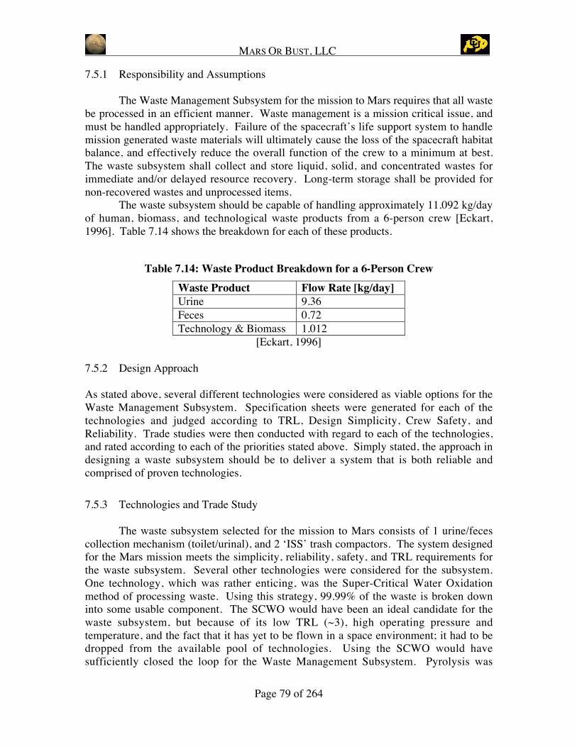
MARS OR BUST, LLC
Page 79 of 264
7.5.1 Responsibility and Assumptions
The Waste Management Subsystem for the mission to Mars requires that all wastebe processed in an efficient manner. Waste management is a mission critical issue, andmust be handled appropriately. Failure of the spacecraft’s life support system to handlemission generated waste materials will ultimately cause the loss of the spacecraft habitatbalance, and effectively reduce the overall function of the crew to a minimum at best.The waste subsystem shall collect and store liquid, solid, and concentrated wastes forimmediate and/or delayed resource recovery. Long-term storage shall be provided fornon-recovered wastes and unprocessed items.
The waste subsystem should be capable of handling approximately 11.092 kg/dayof human, biomass, and technological waste products from a 6-person crew [Eckart,1996]. Table 7.14 shows the breakdown for each of these products.
Table 7.14: Waste Product Breakdown for a 6-Person CrewWaste Product Flow Rate [kg/day]Urine 9.36Feces 0.72Technology & Biomass 1.012
[Eckart, 1996]
7.5.2 Design Approach
As stated above, several different technologies were considered as viable options for theWaste Management Subsystem. Specification sheets were generated for each of thetechnologies and judged according to TRL, Design Simplicity, Crew Safety, andReliability. Trade studies were then conducted with regard to each of the technologies,and rated according to each of the priorities stated above. Simply stated, the approach indesigning a waste subsystem should be to deliver a system that is both reliable andcomprised of proven technologies.
7.5.3 Technologies and Trade Study
The waste subsystem selected for the mission to Mars consists of 1 urine/fecescollection mechanism (toilet/urinal), and 2 ‘ISS’ trash compactors. The system designedfor the Mars mission meets the simplicity, reliability, safety, and TRL requirements forthe waste subsystem. Several other technologies were considered for the subsystem.One technology, which was rather enticing, was the Super-Critical Water Oxidationmethod of processing waste. Using this strategy, 99.99% of the waste is broken downinto some usable component. The SCWO would have been an ideal candidate for thewaste subsystem, but because of its low TRL (~3), high operating pressure andtemperature, and the fact that it has yet to be flown in a space environment; it had to bedropped from the available pool of technologies. Using the SCWO would havesufficiently closed the loop for the Waste Management Subsystem. Pyrolysis was

MARS OR BUST, LLC
Page 80 of 264
another technology that operates at high temperature and high pressure resulting in highpower consumption. This technology would also close the loop of the waste subsystem.All the gas generated would return to the atmosphere subsystem, water will be return tothe water management subsystem and the trivial amount of carbon will be stored. Othertechnologies considered, but not used were electrochemical incineration, photo-catalyticoxidation, and other combustion methods. However, all of these methods either requiredtoo much consumable mass, too much power, or were not considered safe enough to use.Also, it was determined that there would be enough water on board the spacecraft so thatwater loss from not processing the fecal water, would be tolerable. This trade allowed forthe consideration of a flight proven method of handling waste products, instead of onewith a lower TRL.
Figure 7.14: Schematic of the Waste Management Subsystem
There are two inputs for the system: (1) human, and (2) biomass andtechnological wastes, such as spent cartridges from the TCCA and VCD filters. TheWater Management Subsystem will process the urine.The flow of waste through the waste subsystem follows the schematic in Figure 7.14.Human waste is deposited in either the commode or the urinal. Fecal matter andassociated toiletries are deposited by the crewmember into a fecal bag. The fecal bagsare then placed into one of two trash compactors. The compactor for fecal matter willuse small UV degradable bags before placing into larger trash bags. Trash from TCCA(cartridges & filters), food packaging, and micro-filtration devices, are placed into acompactor. Both the fecal waste and other solid waste are then placed into hermetically
To: waste water tank
feces
CommodeUrinal
compactor
From: TCCA food trash microfiltration VCD
trash
fecalstorage
solidwaste
storage
compactor
urine
H2O

MARS OR BUST, LLC
Page 81 of 264
sealed bags for long term storage. The fecal matter will breakdown and become fertilizerfor future mission. During the surface stay (600 days), the crew will place all the trash inthe designated storage area outside of the habitat during the frequent EVA scheduled orbe stored inside the habitat due to the concern about the Mars environmentcontaminations. Whether the storage of trash will be outside or inside will have to bedetermined after performing a study to determine amount of contamination is performed.This is because MOB is very sensitive to the issues surrounding the contamination of thesurface of Mars.
7.5.4 Design
Although many different waste processing methods are readily available here onearth, very few of these technologies have been tested in similar environments to that ofspace, and even fewer have been flight tested in micro-gravity. The Waste ManagementSubsystem selected for this mission, meets the requirements of simplicity, reliability, andsafety. The waste system used has a fixed mass of 279 kg, a consumable mass of 2.3kg/day, and has a total power consumption of 0.22 kW. The toilet/urinal used for themission has been flight proven on both the Space Shuttle, and the International SpaceStation. This system requires minimal power and its reliability is proven. The crew willhave a provision of fecal bags and compactor bags for the duration of the mission plus10%. Having such a large provision ensures that the crew will have enough resources forthe entire mission, plus any contingency. Finally, the waste subsystem selected for themission is capable of handling more than the required 11.012 kg/day of waste. Thisflexibility was an important element in the final selection of this specific system.
One of the potential drawbacks to this system is that it does require crewinteraction for the collection of the fecal matter. While this may have a negativepsychological impact on the crew, overall failure of a more complex waste system wasdeemed to have a much larger impact. Future considerations should give preference tothe Super-Critical Wet Oxidation method and Pyrolysis for processing waste because ofits efficiency and capability of handling both human and technological waste products.The values for heat, power, and volume for the completed waste system are locatedbelow in Table 7.15.
Table 7.15: Heat, Power, and Volume for ECLSS Waste Technologies
Waste System
Component
HeatGenerated
(kW)Power(kW)
Volume(m^3) Mass (kg)
Fecal Compactor 0.220 0.220 0.720 25.94
Solid Waste Compactor 0.110 0.110 0.360 25.94
Pop-up net, stowed config (fecal waste) n/a n/a 0.125 9.00
Pop-up dumpster, stowed config (solid waste) n/a n/a 0.500 205.00
Plumbing (10% of total) n/a n/a 0.171 6.088
Spares 0.033 0.033 0.188 5.797

MARS OR BUST, LLC
Page 82 of 264
Total 0.363 0.363 2.063 277.765
7.6 Food Subsystem
The objective of this stage of the Mars mission project is to provide an analysis of thefood subsystem requirements and available technologies necessary for food supply. Thefunctional requirement is to meet the nutritional needs of the astronauts in a safe andhealthy manner while taking into account the conditions of 1/3g gravity [Eckart, 1996].
7.6.1 Responsibility and Assumptions
The Mars Design Reference Mission document was reviewed to develop an approach toprovide a comprehensive life support subsystem and a food supply for the crew. TheDRM shows that six crewmembers must be supplied with enough food for 600 days stayon the surface of Mars [Drake, 1998]. In order to determine mass and volume of food tosupply crewmembers, an average of 2,200 kCal was assumed for this system. This isbased off the fact that a minimum of 2,000 kCal is needed per person per day to keep theastronauts healthy [Miller, 1994]. Many trade factors needed consideration in the designof the food subsystem.
7.6.2 Design Approach
One of the predominant trade factors is physiological nutritional need versuspsychological palatability and desires. The requirement for this system is to meet thenutritional needs of the astronauts in a safe and healthy manner [Klaus, 2002]. Theintake of food for energy purposes needs to be sufficient to maintain weight andcomposition of the body and allow levels of activity anticipated for operations in space[Lane, 2000]. The basic nutritional needs dictate the amount of food that is necessary tobring. A minimum of 2,000 kCal is needed per person per day to keep the astronautshealthy and an average of 2,200 was chosen for this system [Miller, 1994]. Nutritionalneeds are important but factors related to changes in body composition and energyexpenditure at different levels of gravity must also be taken into account. The relationshipbetween diet and exercise must be considered because that can affect the levels ofkilocalorie intake.
7.6.3 Technologies and Trade Study
In choosing types of food for the mission, considerations include minimal in-flightpreparation, minimal waste (inedible biomass and packaging), ambient stowage, minimalmass, shelf life and good taste. For a long duration mission, stability, variety, andproduction during the mission need to be considered.
Food stabilization defines packaging requirements and necessary mass allocations. Foodsupply stabilization has evolved from food fed through a tube for the Mercury missions todehydrated sources for the Gemini missions to adding thermo stabilized and irradiateditems during the Apollo missions. Current day brings us to the Shuttle (STS) and the

MARS OR BUST, LLC
Page 83 of 264
International Space Station (ISS), both of which have all of the aforementioned items, aswell as intermediate moisture and natural form foods. ISS and STS also have condimentsto add flavor since food tastes bland in space [Klaus, 2002].
Physical-Chemical (PC) systems cannot produce food. However, this system has beenchosen to be a PC system and in so doing, all food must be brought. If food production isconsidered, then those considerations include plants, animals, aquaculture, and othertechnologies. Animals are impractical as that brings up inefficiency factors, thereforethey will not be considered. Aquaculture is more practical because of rapid growth andsteady state production. Aquaculture requires a large mass of water, which can also beused as an emergency buffer for water supply. This is something to consider for futureresearch and design.
All of the aforementioned factors and technologies must be combined to create a systemthat meets nutritional needs, palatable desires, and minimization of waste and mass.
When designing the food subsystem, the first step taken in the design approach was toconsider the requirements, and to identify candidate technologies. These candidatetechnologies were then researched and put into a trade matrix. Once all candidatetechnologies were part of the matrix, any unknown values were researched.Unfortunately due to limited available detailed information, often times because theinformation is proprietary to a company, not all necessary values were found for thecandidate technologies. This posed a problem in calculating ESM and choosing atechnology because any decision to be made would have to be made with a certain lack ofinformation.
The food subsystem is different than the other subsystems because variety is arequirement and in order to achieve this more than one candidate technology must bechosen. For example, a variety of different foods are being brought and will be stabilizedusing different stabilization methods. After the matrix was ranked it was sent to theSystem Engineer to pick the top technologies that best integrate with the rest of the lifesupport subsystems and in some cases the top 4 were chosen. After a final system waschosen, mass calculations were finalized.
To develop a food supply subsystem various parameters had to be explored: food supply,food production, food storage, and food processing.
For this mission, all food will be brought. Bringing all of the food required for surfacestay is necessary for safety precautions, mainly because all of the food supply bio-regenerative technologies have fairly low TRLs. If the astronauts had to rely on bio-regenerative technologies for their food supply then they risk the possibility that thosetechnologies would fail, leaving the astronauts without enough food for the trip. Whenbringing food a variety of stabilization methods were examined. There is always thepossibility of bacteria contaminating one type of food or food stabilized using a certainmethod. This is part of why variety is so important. Because variety was considered arequirement, dehydrated, thermo stabilized, natural form, irradiated, and intermediate

MARS OR BUST, LLC
Page 84 of 264
moisture were chosen for use in this system. Pre-cooked and frozen were eliminated dueto lack of a refrigerator. A refrigerator provided will not be used for storing frozen foodbut will be used for refrigerating drinks and minor food preparations. The total mass forstabilized food is approximately 2,787 kg, which is a minimum value. An extra 10% ofthis value was taken and brought as a buffer. To calculate this mass number, the value of0.62 kg/day per person was taken and multiplied by the number of crewmembers and thelength of the trip [Miller, 1994].
Food storage methods are defined by the way the food required to be stocked. Storagemethods utilized at room temperature are mainly based on different ways of packagingthe food. These include, cellulose used for biodegradable rigid packaging, bioplasticsused for biodegradable rigid packaging, edible rice wafer used for biodegradable rigidpackaging, aluminum or bimetallic tins for thermo stabilized foods, retort pouches forthermo stabilized foods, flexible pouches for natural form foods and intermediatemoisture foods, foil laminate bags for beverages, and dropper bottles for condiments. Allof these packaging methods are going to be used because of the need for variety.Different types of food have to be packaged differently. The other type of food storage isrefrigeration. The candidate technologies include, a Coolant Loop, Vapor-compressionRefrigeration, Stirling Cycle Heat Pump, Thermoelectric Heat Pumps, Thermo acousticRefrigeration, and Phase-change Materials. Due to power constraints, storing food byrefrigeration was not chosen for this system.
Food processing defines how the astronauts prepare the food for consumption. Varioustechnologies that were considered include a microwave (roasting and baking), water re-hydration, fluid immersion, and direct contact and/or radiant heating. Two technologieswere chosen, a microwave that can also be used as a convection oven and grill, and asink/tap that can be used to re-hydrate and heat food as well as be used for drinkingpurposes. The specs for these technologies are in Table 7.16.
Table 7.16: Food Technology SpecificationsFood
TechnologyQuantity Mass
(each)Power(each)
Volume(each)
HeatProduced
CrewTime
TRL
Microwaves(ConvectionOven/ Grill)
2 33 kg (1kW)
~0.3 m3 (1 kW) (62hrs)
6
Sink/tap 1 5 kg 1 kW (~0.4 m3) (1 kW) 0 9
Refrigerator 1 200 kg 1 kW 1 m3 1 kW 0 9
NOTE: Parentheses indicate an educated estimate.

MARS OR BUST, LLC
Page 85 of 264
Figure 7.15: Food System Schematic
7.6.4 Design
Operation of the food subsystem is fairly straightforward. The operation of the system islaid out in the food schematic in Figure 7.15. When it comes time to eat, one or all of theastronauts will retrieve packaged and stabilized food from storage. The food can then beprepared in the microwave or by using water from the sink/tap. The excess food andpackaging is then thrown away.
The final resulting food system is a preliminary system. Many parameters are stillunknown, but the basics values and the structure of the food system have been decided. This primary system is the best system possible while taking into account its integrationinto the entire life support system. This primary food system has a mass of 3,028.63 kgand is made up of stabilized food, a microwave which can also be used as a convectionoven and grill, a sink/tap with hot and cold water to re-hydrate food and for drinkingpurposes. The values for heat, power, and volume for the completed food system arelocated below in Table 7.17.
To: trash compactor
trash
Potable water
microwave water
food preparation
food &drinkFood waste &
packagingfood
storage
H2O
refrigerator

MARS OR BUST, LLC
Page 86 of 264
Table 7.17: Heat, Power, and Volume for ECLSS Food Technologies
Food System
Component
HeatGenerated
(kW)Power(kW)
Volume(m3) Mass (kg)
Microwave Oven/Convection Oven/Grill (2) 1.800 1.800 0.600 66.00
Sink 1.000 1.000 0.400 5.00
Refrigerator 1.000 1.000 1.000 200.00
Plumbing (10% of total) n/a n/a 0.200 27.100
Food (dehydrated) n/a n/a 2.600 2455.20
Spares (10% of total) 0.380 0.380 0.480 275.330
Total 4.180 4.180 5.280 3028.630
7.7 Integrated System
7.7.1 Integration Process
The four systems discussed in the previous sections, Atmosphere, Water, Waste, andFood, combine to form an integrated system that addresses the mission needs regardingenvironment and life support within the habitat. Beyond the ECLSS Subsystem, theECLSS components operate in conjunction with other subsystems to meet mission goals.During the integration process ECLSS collected requests from the other subsystems ofneeds for ECLSS support and also presented requests to other subsystems for support.Trade studies were performed on each of the ECLSS technologies considering theiroverall integration within the MOB Habitat with a focus on minimizing mass,maximizing efficiency, and minimizing mission and program risk. Through this process,solutions were found that meet the needs of both ECLSS and the other MOB subsystems,and the following design emerged.
7.7.2 Integrated Design
The integrated ECLSS design is shown in Figure 7.16. The integrated system providesgreater efficiency than would be possible with four independent ECLS systems. Theinteractions of the four main ECLSS functions are evident in the diagram.

MARS OR BUST, LLC
Page 87 of 264
Figure 7.16: ECLSS Integrated Design
Starting with the Food System and proceeding clockwise around the diagram, the FoodSystem receives potable water from the Water System. This water is used both to re-hydrate food and for drinking with or without powdered drink mixes. The Water Systemalso provides water to the Atmosphere System. This water does not need to undergo theadditional treatment to qualify as potable water, so it exits the Water System as hygienequality water, increasing the efficiency of the overall ECLS Subsystem. The WasteSystem is also integrated with the Water System. When crewmembers eliminate urine itis then passed to the water system for rigorous treatment allowing the ECLS Subsystemto reclaim the valuable water for future use. Finally, the ECLSS design integratescollection of waste, by passing waste from the Food System and Trace ContaminantsControl System to the Waste System. The waste from the Food System will include acombination of packaging plastics and food waste generated during meal preparation andclean up.
AtmosphereSystem
WasteSystem
FoodSystem
WaterSystem
AtmosphericCondenser
Urine
CompactorSolid Waste
Storage
TCCA
FoodTrash
Crew Accommodations(shower, washer, etc.)
FoodPreparation
FecalSPWE
Ventto
MarsAtm.
H2
EDC
Compactor
PretreatmentOxone, Sulfuricacid
Pretreated Urine
VCD
AES Brine water
Ultra Filtration
RO
Milli Q
MCVIodine
Monitoring
Hygiene Water
Iodine RemovalBed
ISE Monitoring
Potable Water
Processed waterLiquid WasteSolid WasteGases

MARS OR BUST, LLC
Page 88 of 264
7.7.3 Integration with other subsystems
The previous discussion and diagram focus on the integration within the ELCSSSubsystem. The interfaces between ECLSS and the other subsystems are presented inFigure 7.17.