manual flow
TRANSCRIPT

8/12/2019 Manual Flow
http://slidepdf.com/reader/full/manual-flow 1/37
MAGNUM MAGNETIC FLOWMETER MANUAL
Introduction 1. About this manual
Section 1 Magnum Flowmeter Basics
1. Components of the Magnum Flowmeter 2. Basic Operating Principles
Section 2 Installing the Magnum Flowmeter
1. Suitable applications
2. Choosing a location
3. The 2" tap
4. Wiring
5. Additional hardware requirements 6. Step-by-Step setup of Magnum
Section 3 Setting up the Magnum
1. Requirements
2. The Magio operating system
a) Logging in
b) Live feed screen
c) Application configuration
d) Output configuration
e) Filtering/Dampening
f) Sending settings to the flowmeter 3. Datalogging (if equipped)
Section 4 Maintenance

8/12/2019 Manual Flow
http://slidepdf.com/reader/full/manual-flow 2/37
1. Hardware
2. Troubleshooting 3. Repairs
About this Manual
All aspects of the Magnum flowmeter are controlled by software, so it made
sense to also "digitize" the operating manual for this instrument as well. Since the
operation of this flowmeter is actually quite simple and straight forward we evenconsidered that the Magio software itself serve as a kind of interactive manual. In
some respects it clearly does this, but there are some issues concerning the
hardware and installation that are not discussed in the software and for which this
"visual" manual is intended and far better suited..
The hypertext format was chosen because of the familiarity of most Computer
users with the Internet browser interface, readily available software in the form
of Netscape and Explorer and other browsers, and the possibility of incorporating
multimedia in this manual.
For those more comfortable with a printed manual it is of course also possible
to produce hard copies of the information contained herein.
MSR Magmeter
1999
Components
The Magnum Flowmeter is made up of a sensor, transmitter,
mounting mechanism and cables.
The Sensor is usually mounted inside the universal mounting
mechanism (Universal for short) ready for installation. The
sensor consists of a 1.5" 316 stainless steel tube, which
houses the magnetic coil. The KYNAR or PEEK end-piece
closes this tube at the end which is inserted into the liquid.
The Hastelloy or 316 SS electrodes protrude from the end-

8/12/2019 Manual Flow
http://slidepdf.com/reader/full/manual-flow 3/37
piece and pick up the voltage, i.e. signal produced by the movement of the
conductive liquid through the magnetic field generated by the magnetic coil. The
cable which leads to the transmitter portion of the Magnum is sealed into the
other end of the sensor.
The Universal allows the attachement to and insertion into any pipe through a 2" NPT tap and ball-valve. The Universal consists of several parts. The threaded
body (anodized aluminum), the nipple (316 stainless steel), which connects to the
ball-valve of the 2" tap, and fitted with a ball bearing mechanism permitts free
rotation of the sensor and upper part of the mounting mechanism. The nipple also
contains 2 o-rings of different materials depending on the application, which seal
the sensor and the outside world from the line pressure inside the pipe. Two nuts
(anodized aluminum) are used to insert the sensor, hold it in place against line
pressure, and lock it into position.
The Transmitter consists of
an anodized aluminum
NEMA 4 enclosure. It
houses the digital electronic
boards which drive the
magnetic coil of the sensor
and process the information
it receives. A 128 x 128
pixel graphic display is
mounted on the front of the
transmitter. Two 5-pin
connectors on the left side
of the transmitter provide access for the sensor cable and the PC/Magio interface
cable. The 10 pin connector on the right-hand side of the transmitter receives
power-in (12-24V DC) and provides signal outputs (4-20mA, RS232, pulse,
alarm). A standard of 10 metres of 2 pair separate shielded cable connect the
sensor and transmitter. The maximum length of this cable may not exceed 50
metres.
The PC interface cable allows connection of the Magnum transmitter to any IBM
based PC via an available serial port. The Magio 3.0 interface software is
required.

8/12/2019 Manual Flow
http://slidepdf.com/reader/full/manual-flow 4/37
IMPORTANT NOTE : The sensor, cable and transmitter of the Magnum are
integral and matched. The sensor will not function without the transmitter. It will
also not function accurately without the exact transmitter and cable with which it
was originally calibrated. The sensor-transmitter cable is part of the flowmeter
calibration. It may not be cut or modified or the Warranty will become void! To
change cable length for a particular application the instrument (Sensor, cable andtransmitter must be returned to the factory.
Basic Operating Principles
The Magnum Magnetic Flowmeter determines the flow of conductive liquids in
pipes. It does so by determining liquid velocity using the the principle of
magnetic induction. A conductor (water, for example) moving through a
magnetic field generated by the Magnum flowmeter (see illustation) will generatea current that is proportional to the velocity of the conductor. The higher the
generated current, the higher the velocity signal.
The Magnum's digital electronics combines the velocity information with
existing information about the pipe size, and processes it based on user
preferences in regards to filtering and range information into a reliable
information about flow. It is important to keep in mind that Magnum is first and
foremost a device to measure velocity. It's ability to provide accurate information
about flow depends on a number of important outside factors that need always betaken into account:
- area of flow as determined by inside diameter of a given pipe needs to be
provided precisely.
- the pipe needs to be completely filled.
- flow in a given application should be fully developed turbulent flow with a
symetrical flow profile.

8/12/2019 Manual Flow
http://slidepdf.com/reader/full/manual-flow 5/37
- the range (scale) chosen should be based on actual current flow and not future
capacity.
- if the electrodes are not fully submerged in conductive liquid measurement is
not possible.
Some allowance can be made for less then ideal application circumstances owingto the ability of the Magnum operating system to compensate if set up
accordingly and properly, and thanks to the fortunate fact that magmeters by
nature are linear in their measurement even if in error. If the above conditions are
met, the Magnum will provide the most accurate and reliable measurement of
any flowmeter technology.
Suitable Applications
Any conductive liquid flowing in a filled/pressurized pipe.
This includes:
Water
Effluent/Sewage
Pulp
Liquors (pulp and paper industry)
Slurries (mining)
Brine
SludgeAny liquid food product
Various chemical mixtures
Unsuitable liquids (due to low conductivity or insulating properties):
Petroleum products
Crude Oil
Vegetable or animal fats (grease)
Demineralized Water
Magnum is a velocity measurement system that relies on correct input data
regarding pipe dimension and a suitable application based on physical laws and
limitations. We cannot guarantee accurate measurement in all possible
applications or suitability for any particular medium (see also Warranty).
8/12/2019 Manual Flow
http://slidepdf.com/reader/full/manual-flow 6/37
WARRANTY
MSR Magmeter Products are warranted to the original purchaser to be free from
defects in workmanship for a period of FIVE
years from the date of purchase. This Warranty may be extended to a secondary purchaser at MSR Magmeter's discretion.
All warranty work will be done without charge during the FIVE year warranty
period. Shipping and brokerage charges are paid by the party returning the
instrument. Damage due to abuse, improper usage or installation, shipping and
handling accidents, or as a result of unqualified service or unauthorized
modification is excluded from this warranty. Installation of the instrument by
anyone other then a licensed instrumentation mechanic may also void the
warranty. A service charge may be incurred for work done on mistreated
products.
MSR Magmeter's liability under this warranty is limited to the repair or
replacement of the defect or defective unit at our factory
and DOES NOT include shipping expenses. We DO NOT accept returns of
instruments for a refund. ALL SALES ARE FINAL.
You may request information on how to obtain service by contacting MSR
Magmeter directly. ALL RETURNS TO MSR MAGMETER FOR EITHER
WARRANTY OR NON-WARRANTY REPAIRS MUST BE APPROVED BY
MSR MAGMETER PRIOR TO SHIPMENT.
"NO OTHER Warranties ARE EXPRESSED OR IMPLIED, Including BUT
NOT LIMITED TO, THE IMPLIED
WARRANTIES OF MERCHANTABILITY AND FlTNESS FOR A Particular
PURPOSE. MSR MAGMETER
MFG. LTD. IS NOT Responsible FOR INCIDENTAL OR CONSEQUENTIAL
DAMAGES." Some states do not
allow the exclusion or limitation of incidental or consequential damages so the
above limitation or exclusion may not apply to
you.
This warranty gives you specific legal rights and you may also have other rights
which vary from state to state.
MSR MAGMETER
Millwoods P.O. Box 32170

8/12/2019 Manual Flow
http://slidepdf.com/reader/full/manual-flow 7/37
Edmonton, Alberta, Canada
T6K 4C2
Tel: 780 662 2171
Fax: 780 662 2146
e-mail: [email protected]
Choosing a Location
Magnum can be installed at any angle on
any pipe. On steel pipes a 2" tap is used,
while platic or concrete pipes require a
saddle arrangement. A vertical installation
(see photo) is most common, butdepending on available space and wether
or not air or foam could be trapped at the
top of the pipe an installation at an angle
or even horizontal may be advantageous.
In order to insure the best possible
measurement some locations are better
suited then others. First and foremost
make certain the pipe is actually full.
Pipes which lead from open bodies ofwater also often promote the building of vortices which interrupt the flow profile
and pull air into the system for some considerable distance. Significant amounts
of Air or air bubbles may interrupt the functioning of the flowmeter. The sensor
needs to be fully submerged in conductive liquid in order to function.
For up and downstream distance from obstacles the general rule of thumb for
most flowmeters is 10 pipe diameters upstram and 5 pipe diameters downstream.
These distances can be reduced the larger the pipe or the faster the flow in it. The
goal is to find a location in which the flow is fully developed and turbulent -
resulting in a very flat and symetrical flow profile. This is the most commoncondition in larger pipes, so they require less straight run on average.
Since there is no scientifically reliable way to positively identify the ideal
location some educated guess-work may be required. Try to choose an
installation location with as much straight run as possible. Avoid close proximity
to valves (especially butterfly-valves), ellbows, junctions with other pipes, and

8/12/2019 Manual Flow
http://slidepdf.com/reader/full/manual-flow 8/37
water intakes from open bodies of water. Due to its configuration and size
Magnum is not much affected by what happens after the measurement location.
If you are certain that the flow profile is asymetrical consider using two or more
Magnum sensors mounted opposite from each other.
The 2" NPT Tap
The Magnum
Flowmeter is installed
on any given pipe
through a 2" tap. The
tap consists of a welded
2" nipple, a short
threadolet and a 2" NPT
full bore gate or preferably ball-valve.
The overall length of
this tap assembly from
the outside of the pipe
to the end of the valve
should not exceed 8
inches on pipes up to
50" diameter. If it is
less then 6 inches a
standard Magnum can be used on pipe sizes up
to 70" diameter.
The tap can be installed on a pipe while in operation using the hot-tapping
method (for hot-tapping equipment suggestion click here). The tap is welded to
the pipe first, and the hole drilled afterwards with a special sealed drill through
the open valve. The valve is closed, the drill removed and Magnum inserted
instead without having to shut down the pipe during any part of this process.
On concrete or plastic pipes a so-called saddle is used to seal and fit a regularsteel/bronze tap for the insertion of Magnum.
Specifications (materials, power consumption, etc.)
Magnum General Specification

8/12/2019 Manual Flow
http://slidepdf.com/reader/full/manual-flow 9/37
1. Instrument Type
Magnetic Inductive Sensor Flow Meter
Service
All conductive liquids flowing in closed pipes
Manufacturer
MSR Magmeter
Pipe size
Universal
Installation
Hot Tap, Universal Mount (installation and removal possible under full line
operation)
Detail Drawing #UNI95NEW
2. Operating Conditions
Parameter Measured
Conductive liquid flow
Ambient Temperature
-20 to +40C
3. Sensor
Sensor Housing Material
316 SS (Stainless Steel)
8/12/2019 Manual Flow
http://slidepdf.com/reader/full/manual-flow 10/37
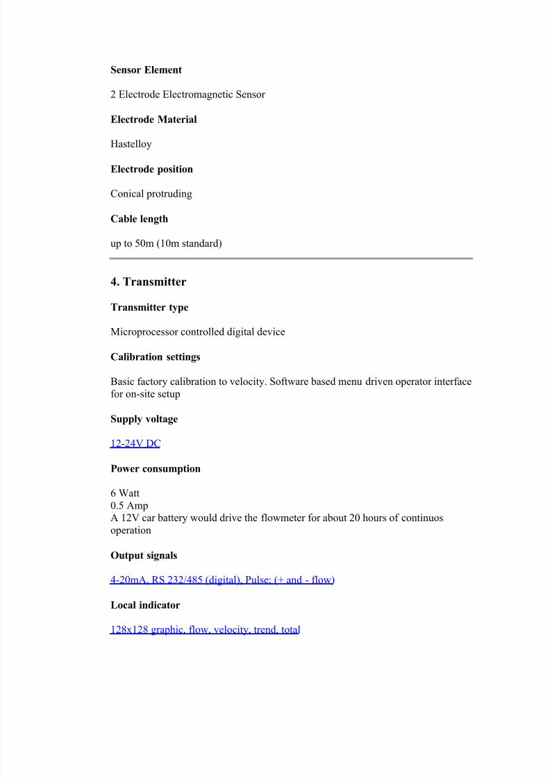
Sensor Element
2 Electrode Electromagnetic Sensor
Electrode Material
Hastelloy
Electrode position
Conical protruding
Cable length
up to 50m (10m standard)
4. Transmitter
Transmitter type
Microprocessor controlled digital device
Calibration settings
Basic factory calibration to velocity. Software based menu driven operator interface
for on-site setup
Supply voltage
12-24V DC
Power consumption
6 Watt
0.5 AmpA 12V car battery would drive the flowmeter for about 20 hours of continuos
operation
Output signals
4-20mA, RS 232/485 (digital), Pulse; (+ and - flow)
Local indicator
128x128 graphic, flow, velocity, trend, total

8/12/2019 Manual Flow
http://slidepdf.com/reader/full/manual-flow 11/37
Memory
Magio 2.0 (DOS) 2000 sample, volatile, adjustable flow recordingMagio 3.0 (WIN9X) none or 20000 sample nonvolatile (optional datalogger)
Enclosure Rating
NEMA 4X
5. Additional Requirements
2" NPT nipple, threadolet and full-bore ball-valve hot tap installation of Universal
Mount

8/12/2019 Manual Flow
http://slidepdf.com/reader/full/manual-flow 12/37

8/12/2019 Manual Flow
http://slidepdf.com/reader/full/manual-flow 13/37

8/12/2019 Manual Flow
http://slidepdf.com/reader/full/manual-flow 14/37
Wiring
All wiring of the standard Magnum flowmeter is done
through the 10 pin connector on the right hand side of
the transmitter. By removing the cover from the
detacheable portion of the connector the user has access
to heavy duty screw-type terminals to connect power
input, signal output and a variety of external equipment.
The MAGIO 3.0 software at one point uses a wiring
diagram as seen below on the left. This is intended for the new Magnum IC
model flowmeter which is not yet in production. Instead use the wiring diagram
on the right, intended for the standard Magnum which also corresponds to the
connector seen above.

8/12/2019 Manual Flow
http://slidepdf.com/reader/full/manual-flow 15/37
The sensor cable is lead to the transmitter through an 8 pin round connector on
the left side of the transmitter casing. Also on the left side is the 5 pin round
connector for the serial port/PC interface cable.
Additional Hardware Requirements
Setup (using Magio 3.0 software)
Laptop or desktop PC with 486 DX processor or better, with 16 MB of
Ram, 40 MB of free hard drive space and free serial port, running MS
Windows 95 or 98.
Mounting (steel pipe):
2" nipple
2" threadolet
2" NPT full bore ball or gate valve
Plastic, asbestos or concrete pipes:

8/12/2019 Manual Flow
http://slidepdf.com/reader/full/manual-flow 16/37
mounting saddle + regular hardware for steel pipes
Power Input:
12 - 24 VDC
(110 VAC - 12 VDC converter is supplied with each instrument)
Signal output (depends on user requirements):
External 4-20mA display
External totalizer
alarm relay
Setting up Magnum
1) Install the 2" Tap
2) Install the Magnum (view movie)
- install mounting system containing sensor on the 2" tap
- check the orientation of the sensor ("v" mark on the top end of
sensor must point in direction of flow).
- attach the sensor cable to the transmitter via the 8 pin connector on
the left side of the transmitter.
- attach the programming cable to the 5 pin connctor on the left side
of the transmitter and the free serial port of your PC.
3) Set up the Magio 3.0 software- start the software on your PC
- establish a connection using "Connect" menu
- enter application information
- take note of the "Insertion Dimension"
- enter output and dampening information
- transmit new settings to flowmeter using "Apply Settings"
- you may now detach your PC unless you want to continue observing
4) Final insertion
- make sure the sensor is attached to the mounting securely.
- make sure the mounting is attached to the tap securely.- open the valve.
- insert the sensor by using the upper nut of the mounting mechanism
and the installation tool.
- check the insertion dimension.
- double check the sensor orientation ("v" mark on the top end of
sensor must point in direction of flow).

8/12/2019 Manual Flow
http://slidepdf.com/reader/full/manual-flow 17/37
Your flowmeter is now operational.
MAGIO 3.0
Interface software for the Magnum digital flowmeter
Magio 3.0 is a Win95/98 native interface for the new Magnum flowmeter. It is
based on the original DOS based Magio interface software for the Magnum
universal flowmeter. Currently Magio 3.0 is modeled to provide the user access
to the site specific setup of the Magnum flowmeter and some test functions. In

8/12/2019 Manual Flow
http://slidepdf.com/reader/full/manual-flow 18/37
the future, as further hardware expansions are added to the basic instrument, the
software may be expanded to control additional functions.
R equirements: IBM PC based Computer
486 or higher CPU (Pentium 100 or above recommended)
16 Mb of RAM (32 Mb or more recommended)25 Mb of free disk space
800 x 600 display resolution at 256 colors
Free serial port (communication with flowmeter)
Port Selection
Magio 3.0 requires a free serial port on your PC/laptop. Laptop computers today
usually have Com 1 available because they are equipped with a touch-pad or a
PS/2 mouse. Desktop systems also have Com 1 available if a PS/2 mouse is
being used. Com 2 is usually reserved for the modem. Unfortunately computers
differ greatly in their configuration and neither port may be available. In this case
it may be necessary to temporarily unplug the mouse from your computer and
start up Win 95/98 without a mouse. Magio 3.0, like the Windows operating
system itself can be operated by Alt-F, Tab, arrow and Enter keys alone. It may
take a little practise, but it is quite possible as a last resort.
Magio 3.0 Login
When you run Magio 3.0 you will be presented
with the above login window. There are 3
levels of access. As standard user no login is
required and you can proceed by clicking
"OK". The second level allows access to
additional features such as data-logging, if the
hardware is present in the Magnum you have purchased (see also under Data-
logging). A login ID and password will be provided at that time.
Datalogging
If your Magnum is equipped with datalogging you will receive a password that
will enable an additional tab in the MAGIO 3.0 software. Currently the capacity
of the chip is about 20,000 recordings (about 14 days at 1 minute log frequency).

8/12/2019 Manual Flow
http://slidepdf.com/reader/full/manual-flow 19/37
The data remains stored even when the power is turned off. The interface below
permitts the setting of date and time at which the log starts and the download of
the stored data to a text file that can then be further processed by programs such
as MS Excell or others.
1) Starting date: The date at which your recording will start in this format(DD:MM:YY)
Y2K note: Although the program displays only the last two digits of the
year, it actually stores all four digits and is fully
Y2K compliant.
2) Starting time: Time at which your recording will start (H:MM:SS)
Note: The datalogger should be initialized at the measurement location. You
should be aware that if
the datalogger is setup elsewhere and then later restarted at the measurement
location the time index will be off.
3) Log frequency: 0-999 minutes interval between recordings. 0 = datalogger
disabled
4) Transmit: Send datalogger settings to flowmeter.
Note: Whenever any settings are changed (flowmeter or datalogger) the
instrument assumes it is being set up for a new
application. In each case you will be prompted to download all recent data
and clear the datalogger. New settings
cannot be transmitted until the logger has been cleared.

8/12/2019 Manual Flow
http://slidepdf.com/reader/full/manual-flow 20/37
The remaining functions are quite self explanatory. The download file will have
the extension *.msr, but will be a simple text file which also includes setup
information about the flowmeter with wich the recording was made. Depending
in the amount of stored data some operations including the download itself may
take a few minutes. You will have options to change the name of the file and
where it will be stored.
Your data download will look something like this:

8/12/2019 Manual Flow
http://slidepdf.com/reader/full/manual-flow 21/37
The "Live Feed" screen is the default start-up screen of the Magio 3.0. It is only
active when a connection with a Magnum flowmeter has been established. If the
software is being used for training and demonstration purposes, or for pre-
recording flowmeter settings the following is what you will see. If a Magnum isattached to a serial port of your computer click on the "Connect" menu and click
on "Open Channel". You may see a message stating that the configured serial
port is invalid. This can be caused if the Magio software is unable to recognize
the ports on your PC, but is usually no cause for concern. Simply click "OK" and
the default Com. (usually com. 1) will be selected regardless (see more important

8/12/2019 Manual Flow
http://slidepdf.com/reader/full/manual-flow 22/37
info on port selection HERE). The software will automatically download all
existing settings from the flowmeter and the display will become syncronized.
Once the flowmeter has been configured for volume an additional totalizer
window will become visible left of the velocity window; as well as an "eraser"
button, allowing clearing of the totalizer.
The units displayed on this screen depend on the settings the Magnum has once it
is connected to Magio 3.0 or which ever you subsequently decide on using. The
above is the original default screen.
In order to change any of the settings with which the flowmeter was shipped, or
to change existing settings a previous user chose originally, click on the "Flow

8/12/2019 Manual Flow
http://slidepdf.com/reader/full/manual-flow 23/37
Config. I" tab and you will get the following screen. Proceed to choose the
desired settings by clicking on pull-down menus and entering numbers. This
should be fairly self-explanatory. The software will automatically calculate and
display the insertion dimension and present the user with a proposed range for
the meter, based on an average flow velocity of 2 m/s (~6ft/s). This represents
most common applications, but can be overridden by the user to chose a specificrange. If you require further information click and hold any of the "help" buttons.
Once you are done click "Continue".

8/12/2019 Manual Flow
http://slidepdf.com/reader/full/manual-flow 24/37
Flow Config. II deals with the output signals supplied by the Magnum
flowmeter. The user has a choice between standard 4-20mA or 0-20mA analog
output. 20mA will automatically correspond to 100% of your chosen range and 4
(0) to zero flow. Magnum can also supply this output for reverse, i.e. "Two Way"
flow, in which case the output must be switched between two external gauges
using the alarm as the switchover relay. The wiring diagram to the lower right ofthe window shows exactly how this needs to be set up. When there is no
flowmeter connected the "Test Devices" buttons will be inactive. If a Magnum is
attached you can test the 4-20mA and pulse outputs. You can also determine the
exact length of pulse Magnum supplies based on the requirements of your
externel hardware. The alarm setting allows you to program one of the pulse
outputs to act as an alarm switch if the flow hits a certain minimum or maximum
flow. When done hit "Continue" to move to the next tab.

8/12/2019 Manual Flow
http://slidepdf.com/reader/full/manual-flow 25/37
The "Signal Dampening" tab deals with the way in which the flowmeter reading
responds to changes in flow. Unfiltered fully developed turbulent flow, as it
exists in most pipes over 3", would produce a seemingly erratic flow reading. In
order to produce a reasonably stable flow reading it is desirable to introduce
some signal filtering. Magio 3.0 offers 7 settings from "none" to "High". The
way in which the flowmeter will react is illustrated by the red line graph below.The higher the filter, the longer it will take Magnum to react to a change in flow
and settle at the new level of flow. It is important to keep in mind that a high
setting will make the flowmeter react very slowly, and in applications where
flows change frequently this may not be a desirable setting. Generally a setting
somewhere in the middle will suit most applications.

8/12/2019 Manual Flow
http://slidepdf.com/reader/full/manual-flow 26/37
If the application is particularly turbulent or noisy it is possible to add another
kind of filter called the "window". Once a steady reading has been established it
dampens the signal for a few percent above and below this reading in order to
achieve as straight a line as possible. If the flow changes above or below this
"window" the flowmeter reacts faster again. It is important to keep this window
as small as possible in order to eliminate undesirable noise, but to keep the meter
able to react to real changes in flow.
Zero Suppression allows the user to force the reading to zero if it falls below a
certain percentage of flow.
When done hit "Continue".

8/12/2019 Manual Flow
http://slidepdf.com/reader/full/manual-flow 27/37
The final tab recaps all settings the user has just chosen for the flowmeter. Once
familiar with the operation of the flowmeter any advanced user can proceed right
to this screen and input data here. When done hit "Accept Settings" to
communicate the new information to the flowmeter. Unless this button is hitnone of the input or changes just made will be communicated to the flowmeter.
After a few seconds the flowmeter will reply with a small window: "Settings
Accepted".
This is also a convenient place to pre-record settings for a specific instrument or
to load an implement settings recorded earlier. For the former, input the desired
settings and under the "File" menu chose "Save Settings". A window will appear
which will allow the user to save a particular setting in under any name and in
any desired directory as a *.MSR file. To load pre-recorded settings choose
"Load Settings" from the "File" menu and find the desired file with a *.MSRlabel. Hit "Apply Settings" to communicate the new data with the Magnum.
If you have a Magnum equipped with datalogger the "Apply Settings" button will
bring up a window that gives you a chance to download the information currently
stored on the datalogger. Once new settings are applied the datalogger will be
cleared. This is meant to insure that the records kept by the logger are consistent
for one specific application.
The "Default Settings" will return both software and flowmeter (if connected) to
the factory settings with which they were shipped.
The "Revert Back" button will revert to the settings last stored in the Magnum
flowmeter.

8/12/2019 Manual Flow
http://slidepdf.com/reader/full/manual-flow 28/37
Datalogging
If your Magnum is equipped with datalogging you will receive a password that
will enable an additional tab in the MAGIO 3.0 software. Currently the capacity
of the chip is about 20,000 recordings (about 14 days at 1 minute log frequency).
The data remains stored even when the power is turned off. The interface below permitts the setting of date and time at which the log starts and the download of
the stored data to a text file that can then be further processed by programs such
as MS Excell or others.
1) Starting date: The date at which your recording will start in this format
(DD:MM:YY)
Y2K note: Although the program displays only the last two digits of the

8/12/2019 Manual Flow
http://slidepdf.com/reader/full/manual-flow 29/37
year, it actually stores all four digits and is fully
Y2K compliant.
2) Starting time: Time at which your recording will start (H:MM:SS)
Note: The datalogger should be initialized at the measurement location. You
should be aware that ifthe datalogger is setup elsewhere and then later restarted at the measurement
location the time index will be off.
3) Log frequency: 0-999 minutes interval between recordings. 0 = datalogger
disabled
4) Transmit: Send datalogger settings to flowmeter.
Note: Whenever any settings are changed (flowmeter or datalogger) the
instrument assumes it is being set up for a new
application. In each case you will be prompted to download all recent dataand clear the datalogger. New settings
cannot be transmitted until the logger has been cleared.

8/12/2019 Manual Flow
http://slidepdf.com/reader/full/manual-flow 30/37
The remaining functions are quite self explanatory. The download file will have
the extension *.msr, but will be a simple text file which also includes setup
information about the flowmeter with wich the recording was made. Depending
in the amount of stored data some operations including the download itself may
take a few minutes. You will have options to change the name of the file and
where it will be stored.
Your data download will look something like this:

8/12/2019 Manual Flow
http://slidepdf.com/reader/full/manual-flow 31/37
Maintenance
Ordinarily the Magnum flowmeter should be ready to operate right out of the box
and should not require any maintenance or service. The Magnum has no
measurement drift and consequently no re-calibration should ever be required.
Still there is a few matters of common sense that you may take into amount:
1) If the flowmeter is intended to be moved frequently it may be a good idea to
grease the thread of the Universal mounting mechanism. If it is intended to stay
in place this may not be necessary.
8/12/2019 Manual Flow
http://slidepdf.com/reader/full/manual-flow 32/37
2) If the liquid being measured contains matter that could collect on the sensor or
electrodes (fiber, grease or mineral build-up) it may be advisable to remove and
clean the sensor periodically as part of your regular maintenance procedures.
This very much depends on your specific application and we can give no
recommendation as to how often this should be done. Here is a demonstration of
how to dis-assemble Magnum.
3) If something is not working as you believe it is supposed to contact the
manufacturer first and if the problem cannot be solved over the phone arrange to
return the instrument to our factory for a free check-up (freight not included). Do
not attempt to modify or repair any part of the instrument yourself or the
warranty will become void.
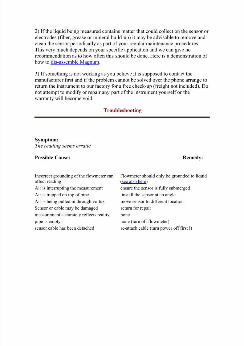
Troubleshooting
Symptom:
The reading seems erratic
Possible Cause: Remedy:
Incorrect grounding of the flowmeter can
affect reading
Flowmeter should only be grounded to liquid
(see also here) Air is interrupting the measurement ensure the sensor is fully submerged
Air is trapped on top of pipe install the sensor at an angle
Air is being pulled in through vortex move sensor to different location
Sensor or cable may be damaged return for repair
measurement accurately reflects reality none
pipe is empty none (turn off flowmeter)
sensor cable has been detached re-attach cable (turn power off first !)

8/12/2019 Manual Flow
http://slidepdf.com/reader/full/manual-flow 33/37
The meter reads low or high compared to another source of information (other
instrument, pump curve, etc.)
The comparison meter is When comparing two instruments make sure they are both

8/12/2019 Manual Flow
http://slidepdf.com/reader/full/manual-flow 34/37
not set to the same range using the same measurement range (scale).
The other instrument is not
properly calibrated
The tendency is to believe the old measurement rather then the
new. If all is set up correctly you should assume that the
Magnum gives you correct information.
Pumps do not always
deliver the specifiedcapacity
Magnum is correct
Doubling the number of pumps does not double the
flow
Magnum is correct
The pipe is not completelyfilled
Magnum is showing more flow then really present because itassumes a filled pipe. Move the meter to a different location.
The meter shows zero when there is flow
Sensor orientation is off point arrow on top end of sensor in flow dirction.
Sensor, cable, or transmitter damaged return for repair

8/12/2019 Manual Flow
http://slidepdf.com/reader/full/manual-flow 35/37
The display stays blank or shows only partial caracters
Display has been damaged return for repair
4-20mA output seems incorrect
Using external power source to drive 4-
20mA circuit
Magnum has a self powered 4-20mA output.
Do not use an
external power source.
Magnum is slow to react to flow
Filter and/or window has been set too high Reduce filter and/or window size
DO NOT:
- attach the sensor cable to the transmitter while it is powered up. - cut or modify the sensor cable. It is part of the calibration.
- submerge the transmitter.
- expose the connector end of the sensor cable to moisture.
- remove the snap-ring from the universal mounting mechanism unless thetap valve is securely closed.
- expose the cable or sensor to temperatures above 100 C unless they are
part of the High Temperture model.
Magnum is supplied with a power pack (110VAC - 12VDC Plug-in class 2 transformer. UL and CSA listed,81J1 E81356). The electrical supply to the transmitter should NOT be grounded under any circumstances.
Ideally the only ground the probe should be connected to is the grounding through contact of the sensor body
with the liquid.
Since there are potential differences between the different grounds provided by earth, electrical and pipe
ground, that could interfere with Magnum, all other grounding of the probe and transmitter should be
avoided.

8/12/2019 Manual Flow
http://slidepdf.com/reader/full/manual-flow 36/37

8/12/2019 Manual Flow
http://slidepdf.com/reader/full/manual-flow 37/37
Repairs
All repairs of the Magnum flowmeter must be conducted at the factory. If it is arepair covered by warranty the user will only be charged for transportation
(unless prepaid). Magnum comes with a 5 year shop warranty on manufacturing
defects. MSR will either repair or replace the damaged flowmeter. All other
repairs are charged for labour and parts used. If you are in doubt about the
performance of a Magnum flowmeter MSR also offers free function check-up of
any flowmeter at the factory at no charge except transportation.
If you need to return a flowmeter for check-up or repair send it to the following
address:
MSR Magmeter
21342 TWP Rd. 510
Sherwood Park, Alberta, Canada
T8G 1E7
If you are outside Canada you will need to mark the waybill and box :
GOODS MADE IN CANADA RETURNING FOR (WARRANTY) REPAIR
If you are outside Canada in addition to the transportation charges there may also
be a nominal fee for brokerage.Under NAFTA (North American Free Trade Agreement) there is no duty for
customers in the USA or Mexico.