manual de partes retro case 580sl series 2 .pdf
TRANSCRIPT

1-1
580 Super L Series 2 Loader Backhoe
Parts Catalog Bur 7-3350
BP97N058
This unit first became available February, 1998.
Bur 7-3350 Copyright © 1998 Case Corporation
C A S E and IH are registered trademarks of Case Corporation Issued February, 1998
1-2 580 Super L Series 2 Loader Backhoe
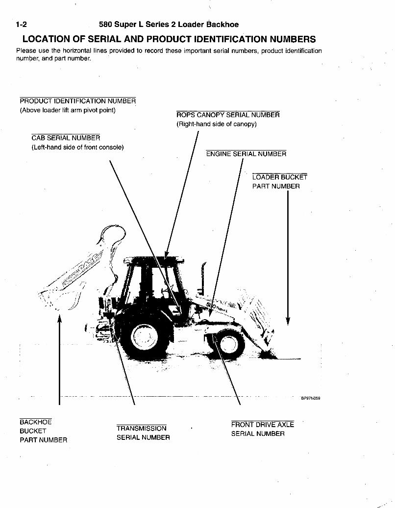
LOCATION OF SERIAL AND PRODUCT IDENTIFICATION NUMBERS Please use the horizontal lines provided to record these important serial numbers, product identification number, and part number.
PRODUCT IDENTIFICATION NUMBER (Above loader lift arm pivot point)
CAB SERIAL NUMBER (Left-hand side of front console)
ROPS CANOPY SERIAL NUMBER (Right-hand side of canopy)
ENGINE SERIAL NUMBER
LOADER BUCKET PART NUMBER
BACKHOE BUCKET PART NUMBER
TRANSMISSION SERIAL NUMBER
FRONT DRIVE AXLE SERIAL NUMBER
580 Super L Series 2 Loader Backhoe 1-3
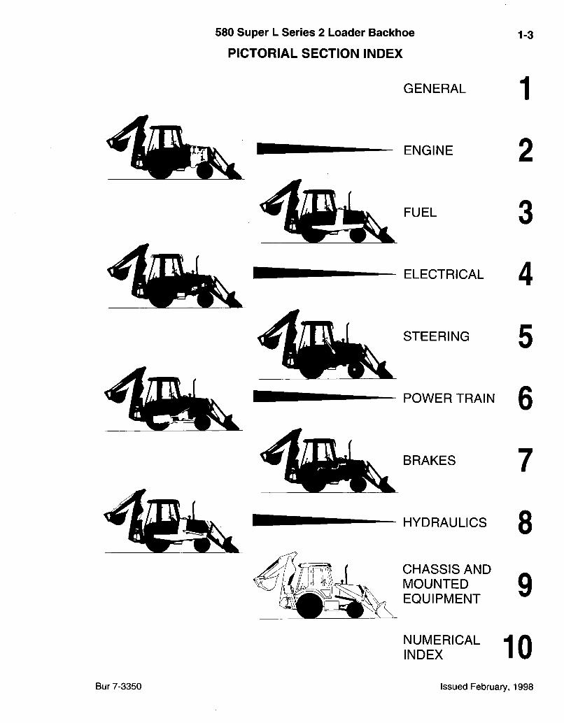
PICTORIAL SECTION INDEX
GENERAL
FUEL
ELECTRICAL
STEERING
POWER TRAIN
BRAKES
HYDRAULICS
CHASSIS AND MOUNTED EQUIPMENT
NUMERICAL INDEX
1
ENGINE 2
3
4
5
6
7
8
9
10 Bur 7-3350 Issued February, 1998
1-4
Indexes
580 Super L Series 2 Loader Backhoe
GENERAL INFORMATION Right-Hand and Left-Hand Identification
Section 1 of this catalog contains a SN and P.I.N, location guide, alphabetical index, pictorial index of the sections included, and pictorial index(es) for quick location of hoses and tubes (and other system components in some catalogs). An alphabetical Index also appears at the beginning of each section. Section 10 is the Numerical Index which lists all part numbers in alpha/numeric order with their page location and reference number.
Illustrations The arrangement of this parts catalog is for easy identifica
tion of parts. All parts are illustrated in "exploded views" In proper relation to each other. Reference numbers used in the illustrations refer to those on the text pages. The text pages list reference number, part number, part description and the quantity required.
Abbreviations P.I.N. "Product Identification Number"
SN "Serial Number"
NSS "Not Serviced Separately" in the part number column indicates this part is not available for service. REF "Reference" in the part number column indicates this part has special service information. The page where this information can be found is given in the part description column. UAR "Use As Required" in the quantity required column indicates the number of parts used is determined by service needs.
The reference to right-hand and left-hand in this catalog is identified by the operator standing at the rear of the basic unit (without rear attachment), looking toward the front of the machine (in normal forward travel). For pages covering any machine attachments, right-hand and left-hand are defined by the operator sitting in the position for proper operation of the attachment.
Catalog Revisions and Supplements Changes to the product may make it necessary to revise or
add pages to this catalog. A cover sheet will list all pages released in a revision or supplement. Each new or revised page will have a new issue date. All revised and new pages must be put into the parts catalog as soon as they are received.
Parts Orders Orders must specify product model, all necessary serial
numbers, correct part number, complete description, quantity required, method of shipment, and shipping address.
Text Format Explanation An assembly may contain service Items. The component
parts of an assembly or subassembly are indented. The quantity required column lists the number of assemblies required for a completed machine, and the number of components required in a complete assembly or subassembly.
The example below Illustrates the use of indents and other text page elements explained on this page.
HYDRAULIC FILTER REF. PART NO. 1 D4356734
D61903 2 NSS 3 D58199
D43800 4 NSS 5 A27994 6 D61948 7 REF 8 843065C1 9 113-323 10 814-8030
DESCRIPTION REO'D. FILTER ASSEMBLY - hydraulic oil, P.I.N. 7534840 and after
HEAD ASSEMBLY - filter HEAD - filter, order D61903 head assennbly VALVE - bypass
KIT - filter element, replaces D35700 elennent kit ELEMENT - filter, order D43800 element kit O-RING - filter HOUSING -filter
CANOPY - ROPS, order form Machinery Price List HOSE - 3353 mm (132 inch) long, reservoir to pump BOLT - hex, 7/16 NC x 1 -3/4 inch 2 BOLT - hex, 8 - 1.25 x 30 mm 4
580 Super L Series 2 Loader Backhoe
ALPHABETICAL INDEX 1-5
Accumulator, Ride Control...: 8-123 Air Cleaner j 2-9 Air Cleaner Mounting j 2-7 Air Conditioner
Blower j 9-137 Compressor and Mounting! 9-145 Condenser ' 9-143 Controls 9-125 Drain Lines j 9-137 Evaporator Core 1 9-141 Fi l ter-air '. 9-135 Receiver-Drier [. 9-143 Ventilation Ducts 9-137
Air Filter - cab 9-135 Alarm - backup 1 4-41 Alarm - warning, engine oil pi;essure 4-19 Alarm - warning, engine water temp 4-19 Alarm - warning, parking brake 4-19 Alternator - electrical 1 4-7 Alternator Mounting i 4-9 Antenna - radio j 4-45 Antirollback - loader 9-11 Auxiliary Hydraulics '
Backhoe 4-47,8-51 - 8-55,9-43 Hand Held 4-21,8-41 -8-49
Axle - Front - four wheel drive Differential .| 6-15 Drive Shaft J 6-19 Housing .; 6-5 Mounting ' 6-3 Planetary 6-13 Ring and Pinion 1 6-17 Shafts 1 6-11 Steering Cylinder 6-9 Swivel Housing ' 6-7
Axle - Front - two wheel drive] 5-15 Axle - Rear Drive
Differential 6-61 Differential Brake 1 7-3 Differential Lock 6-57,6-65 Drive Shaft [ 6-69 Housing 6-59 Mounting 6-55 Parking Brake 1 7-5 Planetary 6-67 Ring and Pinion Gear Set 6-63
B Backhoe
Boom ; ! 9-49 Boom Latch ! 9-53 Boom Lock 8-57,8-59
B Backhoe-Cont.
Buckets 9-63-9-71 Controls (See Controls) Control Tower and Covers 9-25,9-27 Coupler - bucket 9-55 - 9-59 Dipper 9-55 Extendable Dipper 9-59 Frost Point Assembly 9-73 Hydraulics (See Hydraulic Systems) Stabilizers 9-45 Swing Tower 9-47 Valves (See Valves)
Backhoe Auxiliary Hydraulics 8-51 - 8-55 Backup Alarm 4-41 Baffle Plates - front covers 9-85 -9-89 Battery - with cold start 4-15 Battery - without cold start 4-13 Battery Box 9-79 Beacon - rotating 4-43 Bearings -, front wheel 5-17 Belts - fan, alternator, and
compressor 2-3,4-9,9-145 Bel ts-seat 9-103 Block - cylinder 2-39 Blower - air conditioner 9-137 Boom Latch 9-53 Boom Lock 8-57,8-59 Boots
A;ccelerator Pedal 3-9 Backhoe Levers 9-25 Boom Latch Lever 9-53 Brake Master Cylinder ; 7-11 Lamp Socket, instrument
cluster 4-27 Loader Lever..... 4-21,9-3,9-5,9-7 Transmission Gear Shift Lever 6-23 Transmission Shifter Mechanism 6-35 Transmission Shuttle Shift Lever - FNR... 4-17
Box - battery 9-79 Box- too l . . 9-81 Brake - differential, rear axle 7-3 Brake - pai-king, lever 7-13 Brake - parking, rear axle 7-5 Brake Alarm - parking 4-19 Brake Master Cylinder
Assembly 7-11 Hydraulic Circuit 7-9 Mounting 7-7
Brake Pedals 7-7 Buckets - backhoe 9-63 - 9-71 Buckets - loader 9-15-9-19
Bur 7-3350 Issued February, 1998

1-6 580 Super L Series 2 Loader Backlioe
ALPHABETICAL INDEX c
Cab Air Conditioner 9-135 - 9-145 Air Filter 9-135 Blower Housing 9-137 Condenser - air conditioning 9-143 Covers - interior 9-115 Doors and Windows 9-117 - 9-123 Drain Lines - air conditioning 9-137 Electrical and Lighting 4-31,9-125 Evaporator Core 9-141 Frame 9-115 Glass 9-113 Headliner, Louvers, and Dome Lamp 9-133 Heater 9-137,9-139 Insulation 9-115 Panel - cab control 9-125 Receiver-Drier - A/C 9-143 Ventilation Ducts 9-137 Windshield Washers 9-127 Windshield Wipers 9-129,9-131
Cables - battery 4-13,4-15 Camshaft - engine 2-37 Canopy - ROPS 9-147 Chaff Screen 9-93 Chassis - tractor 9-77 Cluster - instrument 4-27 Clutch Cutout 4-11,4-21 Coat Hook 9-115,9-147 Cold Start - dual battery 4-15 Cold Start System - ether 2-13 Column - steering 5-9 Compressor and Mounting - A/C 9-145 Controls
Antirollback - loader 9-11 Backhoe
Excavator Control Pattern 9-39 Foot Swing 9-29 - 9-33 Hand Swing 9-35 ,9-37,9-41
Backhoe Auxiliary 9-43 Boom Latch 9-53 Boom Lock 8-57,8-59 Brake 7-7,7-13 Clutch Cutout 4-11,4-21 Differential Lock - rear axle 6-57,6-65 Extendable Dipper 9-33,9-41 Hand Held Auxiliary 8-49 Loader
Bucket 9-3 Clam 9-5,9-7 Lift 9-3 Self-Leveling 9-9
C Controls-Cont.
Parking Brake 7-13 Return-to-Dig - loader 9-11 Ride Control 8-61,8-63 Self-Leveling - loader 9-9 Steering 5-3 Throttle 3-7,3-9 Transmission Gear Shift 6-23 Transmission Shifter Mechanism 6-35 Transmission Shuttle Shift (F/N/R) 4-17
Control Tower and Covers - backhoe.. 9-25,9-27 Cooler - hydraulic oil 6-21,8-9 Cooling Systems
Engine 2-3 Engine Oil 2-29 Hydraulic Oil 8-9 Transmission 6-21
Core - evaporator, air conditioner 9-141 Countenweight - front 9-75 Coupler - backhoe bucket 9-55 - 9-61 Coupler - quick, loader hydraulic tool 9-23 Couplings - auxiliary hydraulics,
hand held 8-45,8-47 Couplings - hydraulic line disconnect 8-3 Couplings - hydraulic pump to engine 8-3 Covers
Anti-Vandalism Instrument Panel - front 4-23 Instrument Panel - side 4-25
Auxiliary Hydraulic Control 9-25 Backhoe Control Tower 9-25 Baffle Plates - front 9-87,9-89 Battery Box 9-79 Cab Interior 9-115 Chassis Upright 9-93 Cylinder Head 2-33 Fender - plastic/velcro 9-97,9-99 Front Gear 2-19 Instrument Panel 4-23,4-25 Loader Control 4-25 Loader Lift Frame Tubing 3-3,9-79 Pump Guard - front 9-85 Rear Closure Panel - canopy 9-97 ROPS Canopy Post 9-147 Steering Column 4-23
Crankshaft 2-43 Cylinder - brake master 7-11 Cylinder Block 2-39 Cylinder Head 2-33
Bur 7-3350 Issued February, 1998
580 Super L Series 2 Loader BacMnoe
ALPHABETICAL INDEX 1-7
C Cylinders - hydraulic
Boom - backhoe 8-137 Bucket - backhoe 8-141 Bucket - loader 8-129 Clam- loader 8-131 Dipper - backhoe 8-139 Dipper Extension - backhoe 8-143 Lift - loader 8-127 Stabilizer - backhoe 8-133 Steer ing-2WD 5-13 Steer ing-4WD 6-9 Swing - backhoe 8-135
D Decals 9-153-9-157 Differential and Differential Lock -
rear axle 6-57,6-61,6-65 Differential - front axle 6-15 Dipper 9-55,9-57 Dipper - extendable 9-59,9-61 Dipsticks
Oil Level - engine 2-41 Transmission 6-23
Dome Lamp 9-133 Drive Shaft
Front Drive Axle to Transmission 6-19 Rear Drive Axle to Transmission 6-69
Drive Shaft Guards 6-3
E Electrical Circuits and Components
Alternator 4-7 Backhoe Auxiliary Hydraulics 4-47 Backup Alarm 4-41 Battery 4-13,4-15 Blower-cab 9-137 Boom Lock 8-57,8-59 Cold Start System 2-13,4-15 Compressor - air conditioner 9-145 Control Pane l -cab 9-125 Coupler - quick, loader hydraulic
tool 8-65,8-67 Hand Held Auxiliary Hydraulics 4-21 Harness - engine 4-11 Harness - front console 4-17 Harness - lamp, cab 4-31 Harness - lamp, canopy 4-29 Harness - side console 4-19,4-21 Horn 4-41 Instrument Cluster 4-27 Lamp-cab 4-35,4-39 Lamp - ROPS canopy 4-33,4-37
E Electrical Circuits and Components-Cont.
Outlet - power plug 4-21 Radio Ready Package 4-45 Return-to-Dig 9-11 Ride Control 8-61,8-63 Rotating Beacon 4-43 Starter 4-3,4-5 Washer - windshield 9-127 Wipers 9-129,9-131
Engine and Fuel Injection Components Aneroid 3-15 Camshaft 2-37 Crankshaft 2-43 Cylinder Block/Block Heater 2-39,2-41 Cylinder Head and Cover/Thermostat 2-33 Flywheel and Housing 2-45 Fuel Filter 3-11 Fuel Injection Nozzle 3-19 Fuel Injection Pump and Drive 3-17 Fuel Injection System 3-13 Gasket Kits 2-49,2-51 Gear Cover 2-19 Heater - engine oil 2-41 Manifolds 2-21 Oil Filter and Cooler 2-29 Oil Pump and Pan 2-31 Pistons/Connecting Rods 2-47 Pump - transfer, fuel 3-11 Turbocharger Assembly 2-25 Turbocharger System 2-23 Valve Mechanism 2-35 Wastegate Actuator 2-27 Wastegate System 3-15 Water Pump Systems 2-17
Engine Mounting 2-15 Equipment Pump
Assembly 8-71 Mounting 8-3
Evaporator - core, air conditioner 9-141 Exhaust/Intake Manifolds 2-21 Exhaust System and Muffler 2-11
F Fans
Alternator 4-7 Engine Cooling 2-3
Fenders-cab 9-99 Fenders - ROPS canopy, rear 9-97 Filters
Air - engine 2-9 Cab Air 9-135 Engine Oil 2-29
Bur 7-3350 Issued February, 1998
1-8 580 Super L Series 2 Loader Backhoe
ALPHABETICAL INDEX F
Fiiters-Cont. Fuel 3-11 Fuel - In-line 3-3 Hydraulic Oil 8-125 Precleaner 2-9 Transmission Oil 6-27
Floor Plates and Mats 9-95 Flywheel and Housing 2-45 Frame
Backhoe (See Backhoe) Cab 9-115 Canopy 9-147 Coupler - quick tool 9-23 Doors-cab 9-117-9-121 Loader 9-11 Tractor (chassis) 9-77
Frost Point Assembly 9-73 Fuel Filter 3-11 Fuel Injection Nozzle 3-19 Fuel Injection Pump 3-17 Fuel Injection System 3-13 Fuel Level Sensor 3-3 Fuel Reservoir Lines 3-3 Fuses
Auxiliary Hydraulics, Backhoe 4-47 Auxiliary Hydraulics, Hand Held 4-21,8-43 Boom Lock 8-57 Coupler - quick, loader hydraulic tool 8-67 Instruments and Equipment 4-19 Ride Control 8-61 Seat - deluxe air suspension 9-105
G Gaskets - engine 2-49,2-51 Gauges
Cylinder Head Bolt Length - engine gaskets 2-49
Instrument Panel Cluster 4-27 Oil Level - sight 9-79
Grille - chaff screen 9-93 Grille Unit 9-93 Guards
Baffle Plates 9-87,9-89 Drive Shaft 6-3 Loader Crossover Tube 8-15 Loader Self-Leveling Cable 9-9 Mud 9-101 Pump 9-85 Valve - loader control 9-21
H Hand Held Auxiliary Hydraulics 8-41 - 8-49
H Harness - electrical
Adapter - cab 4-19 Adapter - engine 4-19 Auxiliary Hydraulics - Backhoe 4-47 Auxiliary Hydraulics - Hand Held 4-21 Backup Alarm 4-41 Blower Jumper 9-137 Boom Lock 8-57 Cab 4-31,9-125 Canopy 4-29 Chassis Options 4-19,4-47,8-63,8-67 Coupler - quick, loader hydraulic tool 8-67 Engine 4-11 Front Console 4-17 Horn 4-41 Optional Equipment 4-19 Radio 4-45 Ride Control 8-63 Seat 9-105 Side Console 4-19,4-21 Side Console Options 4-19,4-47,8-63,8-67 Transmission Lever -
clutch cutout 4-11 Head - cylinder and cover 2-33 Headliner - cab 9-133 Heater -cab 9-137,9-139 Heater - engine block 2-41 Heater - engine oil 2-31 Hood and Latch Release 9-93 Hook, Coat 9-115,9-147 Horn - electric 4-41 Hub - front wheel 5-17 Hydraulic Systems
Auxiliary Backhoe 8-51 -8-55 Hand Held 8-41 -8-49
Backhoe Boom 8-25 Backhoe Bucket 8-29 - 8-35 Backhoe Dipper 8-27 Backhoe Dipper Extension 8-37 Backhoe Stabilizer 8-21 Backhoe Swing 8-23 Boom Lock 8-57,8-59 Brake Master Cylinder 7-9 Coupler - quick, loader hydraulic
tool 8-65 - 8-69 Differential Lock, rear axle 6-57 Equipment Primary
Oil Cooler Lines and Filter 8-9 Pump and Loader Valve to
Backhoe Valve 8-7
Bur 7-3350 Issued February, 1998
580 Super L Series 2 Loader Backiioe
ALPHABETICAL INDEX 1-9
H Hydraulic Systems-Cont.
Equipment Primary-Cont. Reservoir to Loader Valve
and Loader Valve to Filter .....8-3,8-5 Return Lines 8-9
Loader Bucket 8-13,8-15 Loader Clam 8-17,8-19 Loader Lift 8-11 Loader Valve to Backhoe Valve-
without auxiliary hydraulics, with or without extendahoe 8-39
Ride Control...., ...8-61,8-63 Steeririg 5:5,5-7
Index - numerical 10-2 Injection Nozzle - fuel 3-19 Injection Pump - fuel 3-17 Injection Systerri - fuel 3-13 Injector Nozzle - ether 2-13 Instrument Cluster .. 4-27 Instrument Panels and Covers 4-23,4-25 Intake/Exhaust Manifolds 2-21
Kits Axle, Kingpiri - two-wheel drive front. 5-15 Backhoe Control - excavator control
pattern 9-39 Boom Lock 8-57,8-59 Boom Lock Solenoid Valve 8-121 Brake Discs - rear axle 7-3 Brake Master Cylinder 7-11 Brake Self-Adjuster - Rear Drive Axle 7-3 Cylinders (See Cylinder - Hydraulic) Equipment Pump ......8-71 Filter, Oil - hydraulic .8-125 Harness - non-air conditioned to
air conditioned 4-19 Mirror - rear view 9-149 Radio Ready Package . 4-25,4-45,9-133 Seat (See Seat - Operators) Steering Control Valve - low torque 5-11 Steering Cylinder - front drive axle... 6-9 Steering Cylinder - two wheel drive axle...5-13 Transmission
Oil Pump Piston Valve 6-33 Synchronizer 6-35,6-37,6-41 - 6-45
Universal Joint - drive shaft 6-19,6-69 Valve. (See Valves) Wheel Bearing, front axle .....5-17
L Lamp - dome, cab j— 9-133 Lamps - tractor 4-33 - 4-39 Latch Release - hood.....; ;. 9-93 Levers - control (See Controls) Loader
Antirollback 9-11 Bucket and Cylinder Links 9-13 Buckets 9-15-9-19 Controls (see Controls) Hydraulics (See Hydraulic Systems) Lift Frame - 9-11 Return-to-Dig 9-11
' Self-Leveling 9-9 Support Strut 9-11 Valve Guard 9-21 Valves (See Valves)
Louvers-cab 9-133
M Manifold - intake/exhaust . 2-21 Master'Cylinder - brake and mounting... 7-7,7-11 Mats and Floor Plates 9-95 Mirror - rear view 9-113,9-1.47,9-149 Motor-wiper ,9-129,9-131 Mud Guard 9-101 Muffler - engine exhaust 2-11
N Nozzle - ether injection, cold start 2-13. Nozzle - fuel injection 3-19 Nozzle - windshield washers 9-127 Numerical Index 10-2
O Oil Cooler - engine 2-29 Oil Cooler - hydraulic 6-21,8-9 Oil Filter - engine 2-29 Oil Filter - hydraulic 8-125 Oil Pump and Pan 2-31 Outlet - power plug.. 4-21
P Pads - stabilizers 9-45 Pan -o i l 2-31 Panel - cab control 9-125 Panel - closure, rear - canopy 9-97 Panel - engine side 9-91 Panel - instrument, front and
'side.... 4-23,4-25 Parking Brake 7-13 Parking Brake - rear axle 7-5
Bur 7-3350 Issued February, 1998
1-10 580 Super L Series 2 Loader Bacl^hoe
ALPHABETICAL INDEX p
Pedals Accelerator 3-9 Brake 7-7 Extendahoe Control 9-33 Swing 9-31
Pistons and Connecting Rods 2-47 Plate - pump guard 9-85 Plates - baffle, front covers 9-87,9-89 Plates - floor and mats 9-95 Plug - power outlet 4-21 Precleaner 2-9 Pulley
Alternator 4-7 Compressor Drive 9-145 Crankshaft 2-43 Fan and Water Pump 2-17
Pump Engine Oil 2-31 Fuel Injection 3-17 Fuel Transfer 3-11 Hydraulic Equipment 8-71 Transmission Oil 6-33 Water 2-17 Windshield Washer 9-127
Pump Guard 9-85
R Radiator - engine 2-5 Radiator Shroud 9-83 Radio Ready Package 4-25,4-45,9-133 Reflector - red 9-153 Relays 4-19 Reservoir
Brake Master Cylinder 7-9 Coolant Recovery Bottle 2-3 Fuel 3-3 Hydraulic Oil 9-79 Radiator 2-5 Windshield Washer 9-127
Reservoir Lines - fuel 3-3 Return-to-Dig 9-11 Ride Control 8-61,8-63 Roll Over Protective
Structure 9-115,9-147 Rotating Beacon 4-43
S Screen-Chaff 9-93 Seat - operators 9-103 - 9-111 Self-Leveling Control 9-9 Sender
Air Filter Restriction 2-9
S Sender-Cont.
Transmission Temperature 4-11 Water Coolant Temperature -
engine 4-11 Sensor - fuel level 3-3 Shift Lever - FNR - transmission 4-17 Shifter Mechanism - transmission 6-35 Shroud - radiator 9-83 Side Panels - engine 9-91 Slow Moving Vehicle Emblem 9-151 Solenoids
Boom Lock 8-121 Coupler - quick, loader hydraulic tool 8-65 Four-Wheel Drive, transmission 6-51 Fuel Injection Pump 3-17 Ride Control 8-61
Speakers - radio and tape player 4-45 Spindles - front axle 5-15 Stabilizers 9-45 Starter - engine 4-3,4-5 Starter - mounting 4-9 Steering - two wheel drive
Column 5-9 Control Valve 5-11 Cylinder 5-13 Hydraulic Circuit 5-5,5-7 Wheel 5-3
Steps 3-3,9-79 Stereo - radio 4-45 Sunvisor 9-115,9-147 Support Strut - loader lift frame 9-11 Switches
Air Cleaner Restriction 2-9,4-11 Air Conditioning Control 9-125,9-141 Auxiliary Hydraulics - Backhoe 4-47 Auxiliary Hydraulics - Hand Held 4-21,8-43 Blower 9-125 Boom Lock 8-57 Brake Lamps 4-17,7-7 Clutch Cutout - gear shift
lever handle 4-11 Cold Start 2-13 Coupler - quick, loader hydraulic tool 8-67 Declutch and Differential Lock 4-21 Differential Lock 4-21 Dome Lamp 4-17 Four Wheel Drive 4-21 High Pressure Cutout - air
conditioner 9-143 Horn 4-17 Key and Starter 4-21 Lamps - driving, work and flood 4-21
Bur 7-3350 Issued February, 1998
580 Super L Series 2 Loader Backhoe
ALPHABETICAL INDEX 1-11
s Switches-Cont.
Lamps - hazard, flasher 4-17 Low Pressure - air conditioner 9-141 Oil Pressure 4-11 Parking Brake 7-5 Return-T6-big 4-11,9-11 Ride Control 8-63 Rotating Beacon 4-21 Seat - operators, limit 9-103 Temperature - engine coolant 4-11 Temperature Oil - rear axle 6-59 Transmission Control Solenoid 4-11,6-35 Transmission Shuttle Shift (FNR) 4-17 Turn Signal..... -4-17 Windshield Washer 9-127 Windshield Wiper. 9-129,9-131
T Tachometer - electric 4-27 Tank - fuel 3-3 Tank - hydraulic oil 9-79 Teeth - buckets 9-63 - 9-71 Thermostat - engine .....2^33 Throttle - engine .....'3-7,3-9 Tires and Wheels 5-19,6-53 Tool Box ,....9-81 Tool Coupler - quick disconnect 9-23 Tool Tray 4-25 Tower - backhoe control and covers ....9-25,9-27 Tower - swing 9-47 Transmission
Cooling System.. 6-21 Dipstick 6-23 Fi l ter-oi l 6-27 Housing. 6-29,6-31 Idler and Primary Shaft 6-39 Input Shaft 6-41 Mounting 6-23 Output Shaft. 6-47 Pump - oil 6-33 Secondary Shaft 6-43,6-45 Shift Lever 6-23 Shifter Mechanism 6-35,6-37 Valve - control.... -6-49 Valve - solenoid 6-51
Turbocharger and System 2-23,2-25 Turn Signal Switch 4-17
V Valve Mechanism - engine .2-35
V Valves
Auxiliary - Backhoe 8-51 Auxiliary - Hand Held.... 8-117,8-119 Backhoe Control
Assembly - with extendable dipper, with auxiliary hydraulics 8-95
Assembly - with extendable dipper, without auxiliary hydraulics 8-93
Assembly - without extendable dipper, with auxiliary hydraulics 8-91
Assembly - without extendable dipper, without auxiliary hydraulics 8-89
Mounting 8-21 Sections
Auxiliary Option 8-115 Boom 8-105,8-107 Bucket 8-99 Dipper 8-101 Dipper Extension 8-113 Inlet/Outlet 8-97
. Stabilizer 8-103 Swing 8-109,8-111
Loader Control Assembly - three spool 8-75 Assembly - two spool 8-73 Circuit Relief - bucket section 8-87 Guard - loader valve 9-21 Mounting 9-3 Sections
Bucket 8-79 Clam 8-85 Inlet : 8-77 Lift 8-81 Outlet 8-83
Solenoid Valves Auxiliary Hydraulics - hand held 8-41 Boom Lock 8-121 Coupler- quick, loader tool..... 8-65 Differential Lock, rear axle 6-57 Four-Wheel Drive, transmission 6-51 Ride Control 8-61
Steering Control 5-11 Transmission Control 6-49
Valve Stem - wheel 5-19,6-53 Vents - louvers, cab 9-137 V isor -sun 9-115,9-147
W Washer - Windshield 9-127 Wheel - steering 5-3 Wheels and Tires 5-19,6-53 Wiper - cab window 9-129,9-131
Bur 7-3350 Issued February, 1998
1-12
\
580 Super L Series 2 Loader Backhoe 1-13
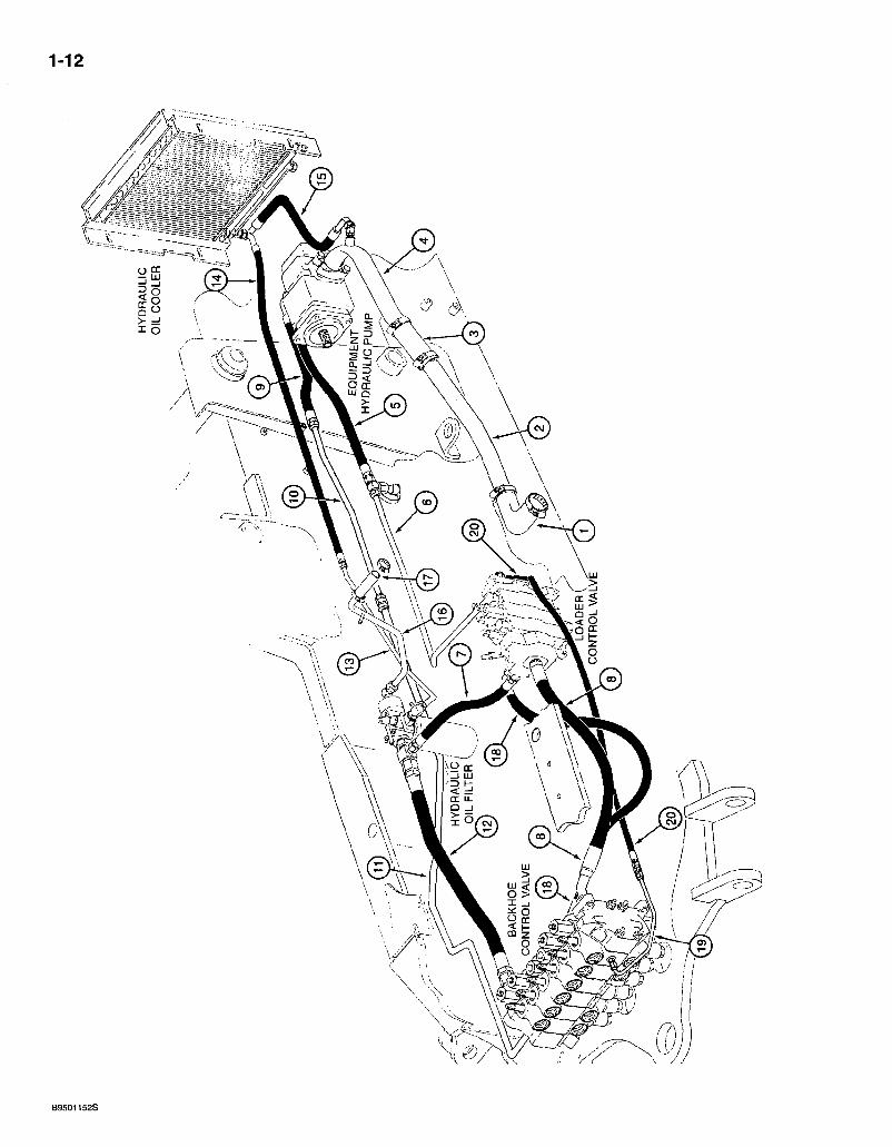
PICTORIAL INDEX EQUIPMENT HYDRAULICS
HYDRAULIC PUMP TO OIL FILTER, CONTROL VALVES AND RETURN TO TANK
REF. DESCRIPTION PAGE
1 Suction hose at hydraulic tank 8-3 2 Suction tube at hydraulic tank 1... 8-3 3 Coupler hose : ^ i . •• 8-3 4 Suction tube at hydraulic equipment pump .........i 8-3 5 Hose,at large pump section port 8-3 6 Tube at tee to loader control valve inlet 8-3 7 Loader valve to filter hose.. 8-5 8 Hose at loader valve power beyond port to backhoe control valve inlet 8-7 9 Hose at small pump section outlet port... 8-7 10 Tube between small pump section hose to tube at backhoe valve outlet section 8-7 11 Tube to inlet port on backhoe control valve outlet section 8-7 12 Return hose at backhoe control valve to filter........ 8-9 13 Oil filter to oil cooler tube 8-9 14 Hose at oil cooler .8-9 15 Oil cooler return hose ^.8-9 16 Return to tank tube ; '. 8-9 17 Return to tank hose 8-9 18 Swing supply hose at loader valve inlet section lower port to backhoe valve
swing section 8-39 19 Pilot tube at backhoe valve swing section center port to loader control valve
inlet section ; 8-39 20 Signal hose at backhoe control valve swing section to loader control valve
. inlet section 8-39
Bur 7-3350 Issued February, 1998
1-14
B94100338
580 Super L Series 2 Loader Baclthoe 1-15
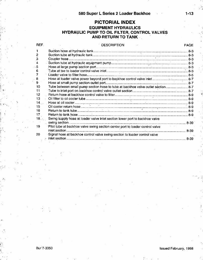
PICTORIAL INDEX LOADER HYDRAULICS
LIFT AND BUCKET CYLINDERS
REF. DESCRIPTION PAGE
1 Tube from upper lift.pqrt of loader control valve to rod end of left-hand lift cylinder 8-11 2 Tube from lower lift port of loader control valve to closed end of right-hand lift cylinder 8-11 3 Tube from lower lift port of loader control valve to closed end of left-hiand lift cylinder 8-11 4 Tube from upper lift port of loader control valve to rod end of right-hand lift cylinder 8-11 5 Hoses.at lift cylinder closed end 8-11 6 Hose at upper port of control valve to lift cylinder rod end..... 8-11 7 Tube at bucket section upper port 8-13 8 Tube at bucket section lower port 8-13 9 Hose at loader arm pivot 8-13 10 Lower tube on right-hand lift arm from bucket section upper port to closed end of
bucket cylinders 8-13 11 Upper tube on right-hand lift arm from bucket section lower port to bucket cylinder
rod end 8-13 12 Rear crossover tube at upper liftframe tube to rod end of bucket cylinder... 8-13 13 Front crossover tube at lower lift frame tube to bucket cylinder closed end 8-13 14 Hose at bucket cylinders 8-13 15 Tube at bucket cylinder rod end 8-13 16 Tube to right-hand bucket cylinder closed end .8-13 17 Tube at left-hand bucket cylinder closed end 8-13
Bur 7-3350 Issued February, 1998
1-16
LEFT-HAND CLAM CYLINDER
RIGHT-HAND CLAM CYLINDER
LOADER CONTROL VALVE
B9410028S
580 Super L Series 2 Loader Backhoe 1-17
PICTORIAL INDEX LOADER HYDRAULICS
CLAM CYLINDER
REF. DESCRIPTION PAGE
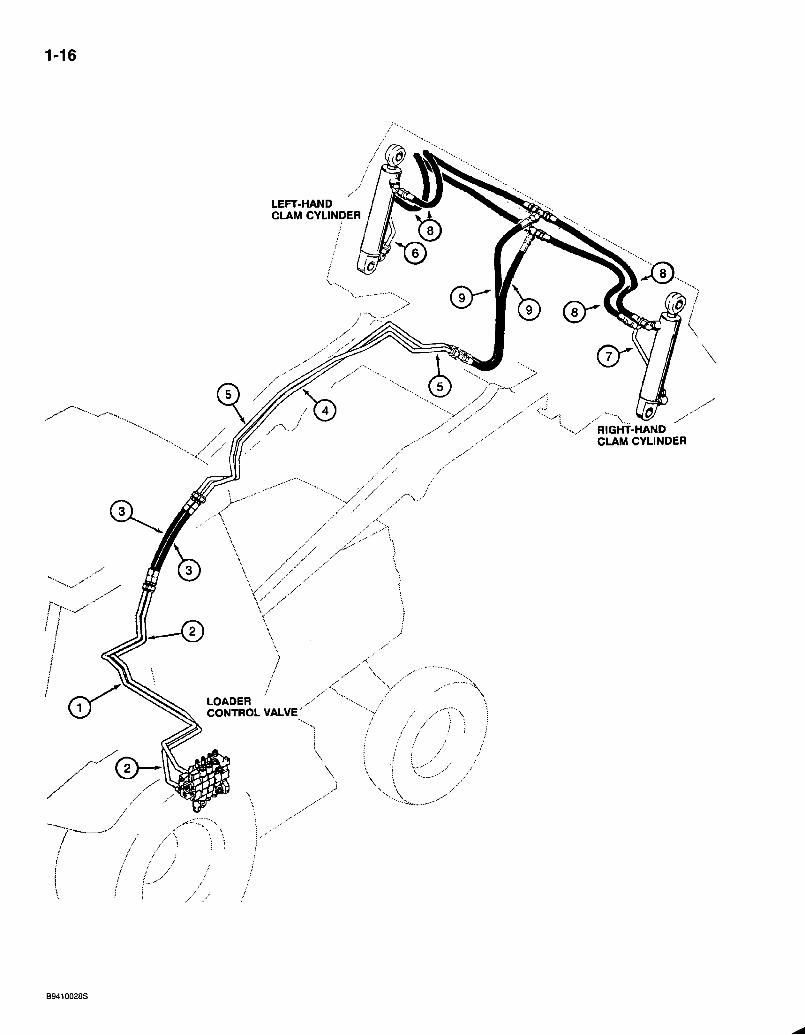
1 Tube at upper port auxiliary section of loader control valve to hose at loader arm pivot 8-17 2 Tube at lower port auxiliary section of loader control valve to hose ati loader arm pivot 8-17 3 Hose at loader arm pviot 8-17 4 Lower tube on loader lift frarhe 8-17 5 Upper tube on loader lift frame 8-17 6 Tube at left-hand clam cylinder 8-19 7 Tube at right-hand clam cylinder 8-19 8 Right-hand and left-hand^clam cylinder hoses .V. J . . . . . . . . 8-19 9- Lift arm:hoses: : 8-19
Bur 7-3350 : Issued February, 1998.
1-18
LEFT-HAND SWING CYLINDER
BACKHOE CONTROL VALVE
RIGHT-HAND SWING CYLINDER
RIGHT-HAND STABILIZER CYLINDER
B9410026S
580 Super L Series 2 Loader Backhoe 1-19
PICTORIAL INDEX BACKHOE HYDRAULICS
STABILIZER CYLINDER AND SWING CYLINDER
REF. DESCRIPTION PAGE
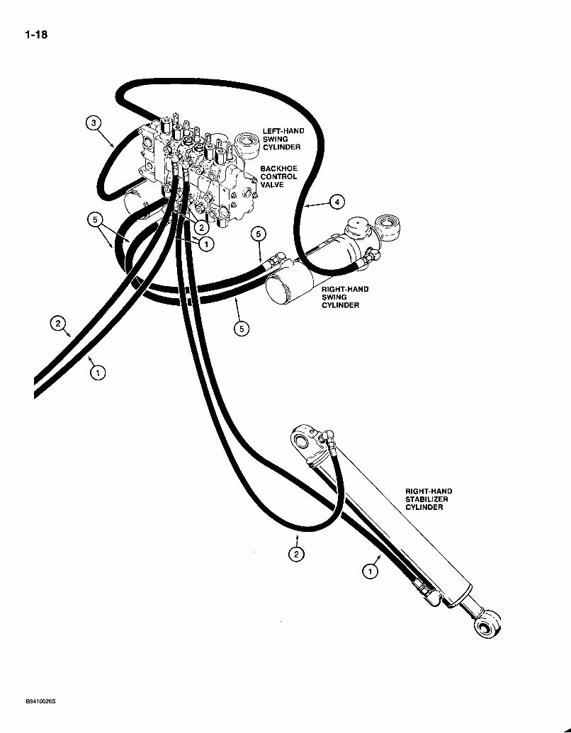
1 Hose at stabilizer cylinder rod ends to backhoe control valve stabilizer section lower ports , 8-21
2 Hose at stabilizer cylinder closed ends to backhoe control valve stabilizer section upper ports 8-21
3 Hose at backhoe control valve swing section upper port to outer rod end of left-hand swing, cylinder : ; 8-23
4 Hose at backhoe control valve swing sectibn lower port to outer rod end of right-hand swing cylinder ! ..A..... 8-23
5 Crossover hose i 8-23
Bur 7-3350 Issued February, 1998
1-20
©
O IT
8 UJ
o
B9410030S
580 Super L Series 2 Loader Backhoe 1-21
PICTORIAL INDEX BAGKHOE HYDRAULICS
*BOOM, DIPPER, AND BUCKET
REF. DESCRIPTION PAGE
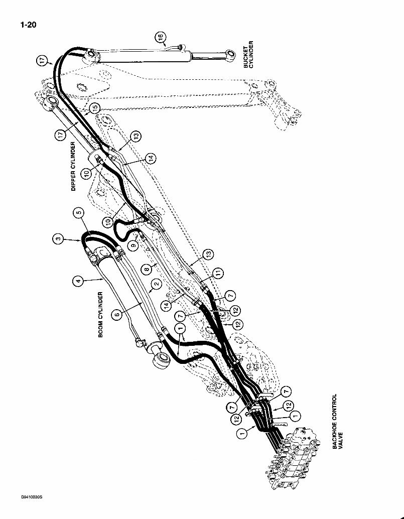
1 Hoses at control valve through swing tower to boom 8-25 2 Tube to boom cylinder closed end hose 8-25 3 Boom cylinder closed end hose 8-25 4 • Boom cylinder rod end tube 8-25 '5 Hose to boom' cylinder rod end tube 8-25 6 Tube to boom cylinder rod end hose 8-25 7 Hoses at control valve through swing tower to boom for dipper 8-27 8 Tube to dipper cylinder closed end hose 8-27 9 Hose at dipper cylinder closed end !; 8-27 10, Hose at dipper cylinder rod end ...8-27 11 Tube to dipper cylinder rod end hose 8-27 12 Hoses at control valve through swing tower to boom for bucket 8-29 13 Tube.on right-hand side of boom, to bucl<et cylinder rod end hose 8-29 14 Tube on left-hand side of boom, to bucket cylinder closed end hose..... 8-29 15 Hose to bucket cylinder rod end tube 8-29 16 Bucket cylinder rod end tube 8-29 17 Hose at bucket cylinder closed end 8-31
* N P T E S : See page 1-23 for tubes and hoses used on models with extendable dipper.
Bur 7-3350 Issued February, 1998
1-22
BUCKET CYLINDER
EXTENDABLE DIPPER CYLINDER
J
BACKHOE CONTROL VALVE
B9410027S

580 Super L Series 2 Loader Bacl<hoe 1-23
PICTORIAL INDEX BACKHOE HYDRAULICS
EXTENDABLE DIPPER
REF. DESCRIPTION PAGE
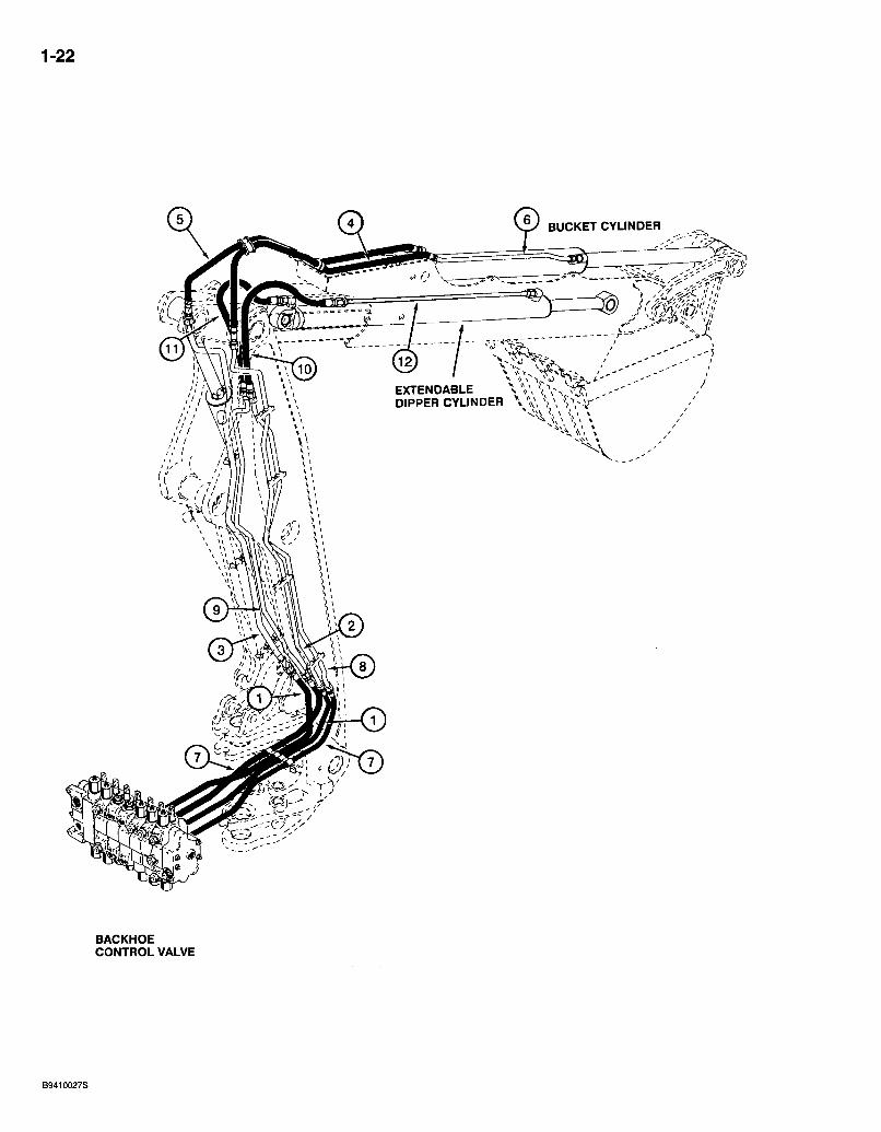
1 Hoses at control valve through swing tower to boom 8-33 2 Tube on right-hand side of boom to bucket cylinder rod end hose 8-33 3 Tube on left-hand side of boom to bucket cylinder closed end hose 8-33 4 Hose to bucket cylinder rod end tube 8-33 5 Hose to bucket cylinder closed end 8-33 6 Bucket cylinder rod end tube 8-35 7 - Hoses at control valve through swing tower to boom for extendable dipper circuit 8-37 8 Tube on boom to extendable dipper cylinder rod end hose 8-37 9 Tube on boom to-extendable dipper.cylinder closed end hose 8-37 10 Hose at extendable dipper cylinder rod end tube 8-37 11 Hose at extendable dipper cylinder closed end 8-37 12 Tube at extendable dipper cylinder rod end 8-37
Bur 7-3350 Issued February, 1998

580 Super L Series 2 Loader Backhoe 2-1
ALPHABETICAL INDEX ENGINE
DESCRIPTION P A G E Air Cleaner and Air Intake Parts 2-7 Air Cleaner Assembly 2-9 Camshaft 2-37 Cold Start System 2-13 Cooler-Oi l 2-29 Cover - Gear, Front 2-19 Crankshaft '. 2-43 Cylinder Block.and Block Heater.... 2-39,2-41 Cylinder Head and Valve Mechanism 2-35 Cylinder Head, Cover, and Thermostat 2-33 Engine Mounting 2-15 Fan ; : 2-3 Fi l ter-Oi l : :2-29 Flywheel and Housing 2-45 Gasket Kits : 2-49,2-51 Heater
Engine Block 2-41 Engine Oil ...2-31 .
Manifold - Exhaust/Intake 2-21 Muffler and Exhaust System 2-11 Pan-O i l . . , .....2-31 Pistons and Connecting Rods .2-47 Precleaner Assembly 2-9 Pump : Oil..:: : : 2-31
W a t ^ 2-17 Radiator and Mounting Parts 2-3 Radiator Assembly 2-5 Thermostat ,. .2-33 Turbocharger Assembly 2-25 Turbdcharger System 2-23 Wastegate Actuator .2-27
Bur 7-3350 Issued February, 1998
2-2
eg)
BT97M203

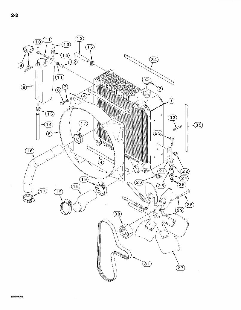
580 Super L Series 2 Loader Backhoe RADIATOR, FAN AND MOUNTING PARTS
USED WITH 291288A1 HEAVY DUTY OIL COOLER
2-3
REF. PART NO. 1 239739A1
2 A170241 4 • 233272A1
5 186433A1 6 806-8016 7 895-15008 8 131084A1 9 1547924C1 10 806-8050 11 895-11008 12 132215A1 13 132218A1
14 132217A1 15 A171099 16 .232366A1 17 214-1432 18 141513A1 19 214-1440 20 217-92 21 121501A1
22 614-8016 23 814-10050 24 K691987 25 D52276 26 832-10410 27 185377A1 27 228133A1 28 814-10070 29 496-21041 30 A184545 31 J925953
33 614-8016 34 235040A1
35 235038A1
LI 26767
DESCRIPTION REQ'D. RADIATOR ASSEMBLY - engine coolant, heavy duty, parts list page 2-5, used with 291288A1 heavy duty oil cooler, see page 6-21 for cooler and baffles 1
CAP - radiator, 15 psi . . . . 1 SEAL - adhesive-backed, 6 (1/4) x 20 (25/32) x 404 mm (15-29/32 inch) long, radiator to shroud, upper and lower 2 SHROUD- fan 1 BOLT - heXi self-locking, 8 -1.25 x 16.mm, class 10.9 4 WASHER - flat, 9 x 20 x 1.6 mm 4.. RESERVOIR - coolant recovery bottle 1
CAP - recovery bottle 1 BOLT - hex, self-locking, 8 - 1.25x 50 mm, class 10.9, . 2 WASHER - flat, 9 x 17 x 1.6 mm 4 SPACER - bottle 2 HOSE - 591 mm (23-1/4 inch) long, coolant recovery, cut from L I 26767 hose 1 HOSE -125 mm (4-15/16 inch) long, coolant.overflow 1 CLAMP - spring-type, hose, retaining . 3 HOSE - radiator, upper 1 CLAMP - adj, 1-9/16 - 2-1/2 inch dia . .2 HOSE - radiator, lower. 1 CLAMP - adj, 2-1/16 - 3 inch dia . . . . , 2 VALVE-dra in , 1/4 inch PT, drain . ! 1 BRACKET - radiator mounting, lower, see page 9-83 for upper bracket that attaches to the radiator shroud. 2 BOLT - hex, full threads, 8 - 1 . 2 5 x 16 mm .4 BOLT - hex, 10 -1 .5 x 50 mm .2 WASHER-f la t , special 4 INSULATOR - rubber, mount,, radiator 2 NUT - hex, self-locking, 10 mm - 1 . 5 . . . 2 FAN - engine cooling, without air conditioning.. ; 1 FAN - engine cooling, 39 degree, with white identification dot 1 BOLT - hex, 10 - 1.5 x 70 mrri 4 WASHER - flat, 13/32 x 13/16 x 3/32 inch, hardened 4 SPACER- fan 1 BELT - fan, V-ribbed, alternator and fan, see page 9-145 for belt used on air conditioning compressor 1 BOLT - hex, full threads, 8 -1.25 x 16 mm, if used 2 SEAL - foam, adhesive-backed, 20 (25/32) x 542 (21-11/32) x 6 mm (1/4 inch), horizontal, radiator to cooler. 2 SEAL - foam, adhesive-backed, 20 (25/32) x 480 (18-29/32) x 10 mm (3/8 inch), vertical, radiator to cooler 2
HOSE - bulk, 8 (5/16) ID x 2336 mm (92 inch) long 1
Bur 7-3350 Issued February, 1998
2-4
^ ^ ^ ^ ^ ^
BT97B260

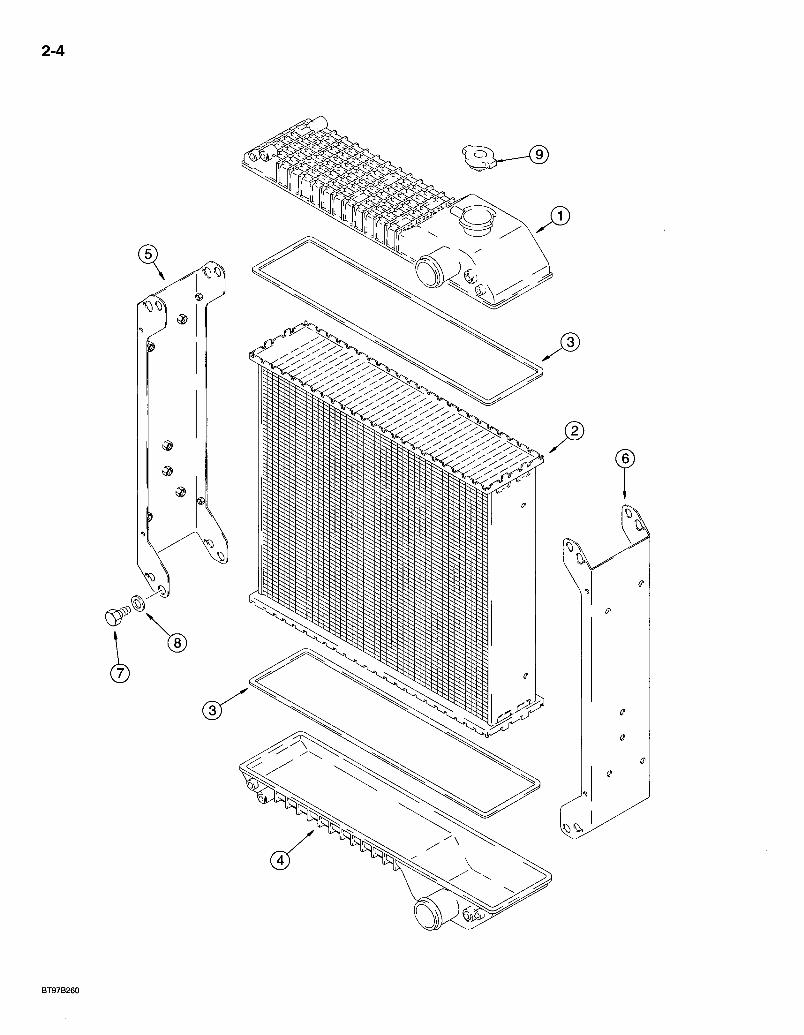
580 Super L Series 2 Loader Backhoe RADIATOR ASSEMBLIES
2-5
REF. PART NO. 239739A1
1 175161A1 2 257434A1 3 175163A1 4 175162A1 5 175164A1 6 175165A1 7 - 614-8012
- 8 895-11008 9 A170241 10 NSS 11 NSS
DESCRIPTION REQ'D. RADIATOR ASSEMBLY - engine coolant, heavy duty, 5 row, used with 291288A1 heavy duty oil cooler, see page 6-21 for cooler 1
TANK-upper 1 CORE - radiator, 5 row. . . 1 GASKET - core, upper and lower . . . . .2 TANK - lower . .1 BRACKET - left-hand, radiator V BRACKET - right-hand, radiator 1 BOLT - hex, full threads, 8 -1.25 x 12 mm 8 WASHER - flat, 9 x 17 x 1.6 mm '8 CAP - radiator, 15 psi 1 SEAL - foam, side channel brackets, not shown 2 SEAL - foam, corners, side channel brackets, not shown 4
Bur 7-3350 Issued February, 1998
2-6
BT97N115
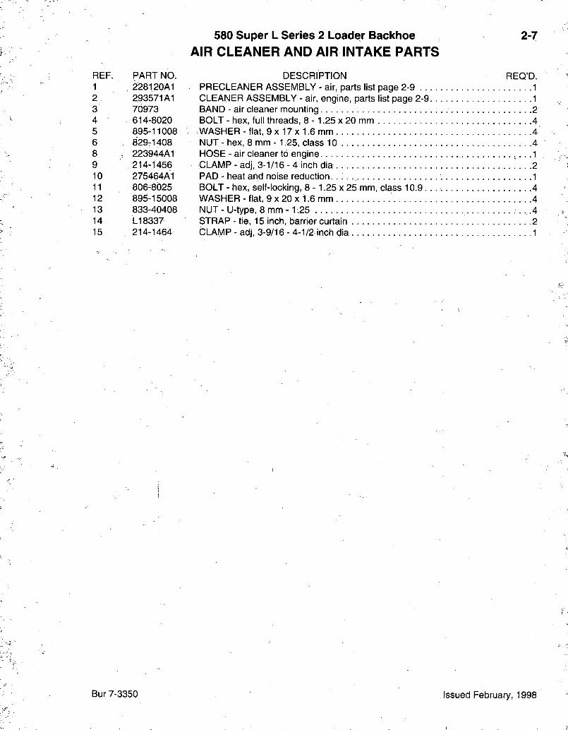
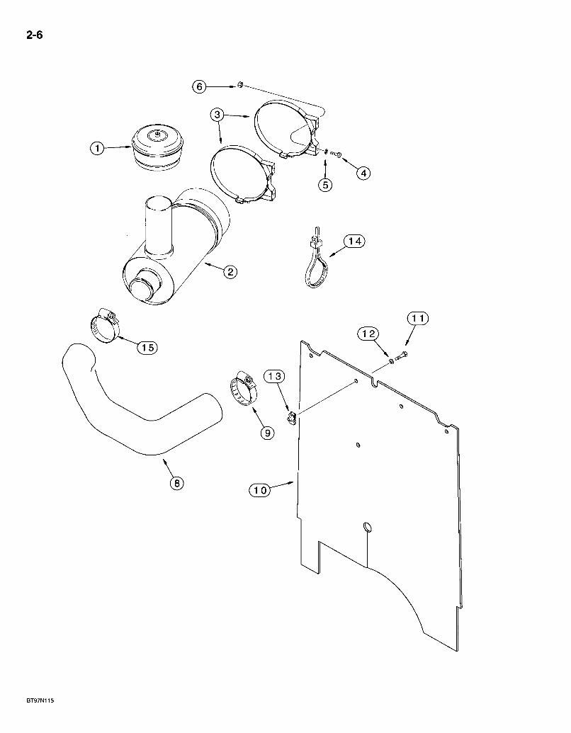
580 Super L Series 2 Loader Backhoe AIR CLEANER AND AIR INTAKE PARTS
2-7
REF. PART NO. 1 228120A1 2 293571A1 3 70973 4 614-8020 5 895-11008 6 829-1408 8 ; 223944A1 9 214-1456 10 275464A1 11 806-8025 12 895-15008 13 833-40408 14 LI 8337 15 214-1464
DESCRIPTION REQ'D. PRECLEANER ASSEMBLY - air, parts list page 2-9 . .1 CLEANER ASSEMBLY - air, engine, parts list page 2-9 1 BAND - air cleaner mounting 2 BOLT - hex, full threads, 8 - 1.25 x 20 mm 4 WASHER - flat, 9 x 17 x 1.6 mm 4 NUT - hex, 8 mm -1.25, class 10 . . . 4 HOSE - air cleaner to engine •, • • 1 CLAMP - adj, 3-1/16 - 4 inch dia 2 PAD - heat and noise reduction. 1 BOLT - hex, self-locking, 8 - 1.25 x 25 mm, class 10.9 4 WASHER - flat, 9 x 20 x 1.6 mm 4 NUT - U-type, 8 mm -1.25 • • •4 STRAP - tie, 15 inch, barrier curtain 2 CLAMP - adj, 3-9/16 - 4-1/2 inch dia 1
Bur 7-3350 Issued February, 1998
2-8
REF.
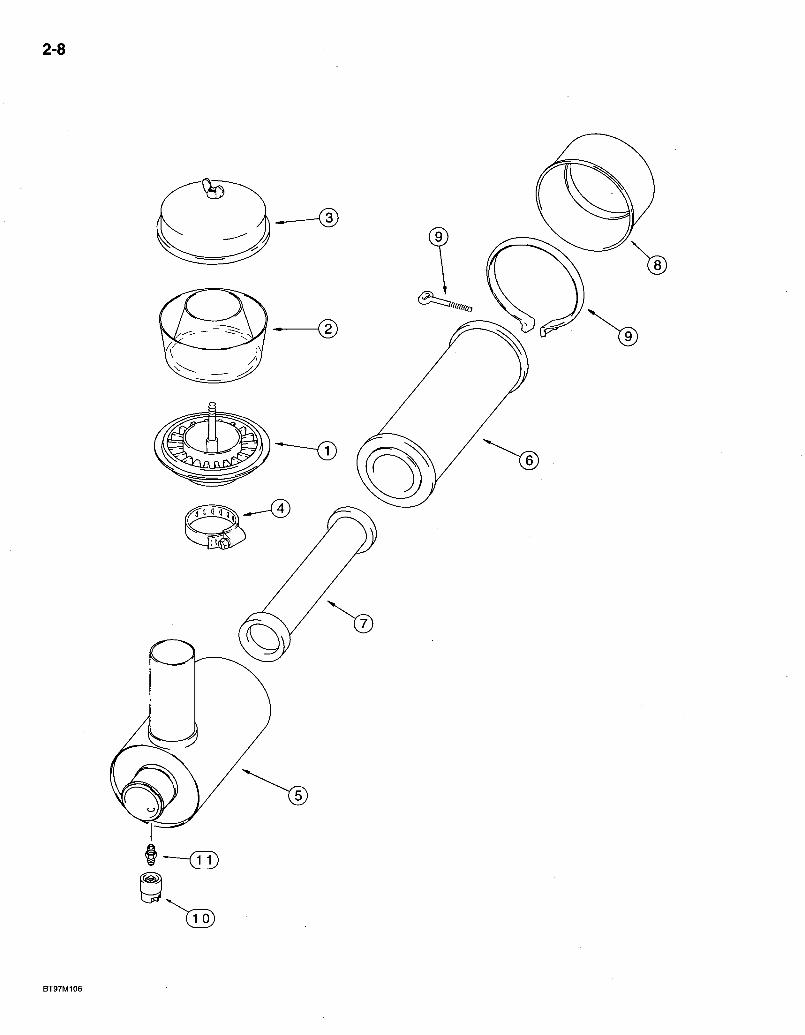
580 Super L Series 2 Loader Backhoe AIR CLEANER AND PRECLEANER ASSEMBLIES
PART NO. DESCRIPTION
PRECLEANER ASSEIVIBLY
2-9
REQ'D.
1 2 3 4
5 6 7 8 9 10 11
228120A1 NSS 277377R1 A42465 214-1464
293571A1 226378A1 N S S . 222421A1 222422A1 247743A1 R21391 292740A1 D36264
PRECLEANER ASSEMBLY - air. BODY - precleaner BOWL - precleaner COVER - precleaner CLAMP - adj, 3-9/16 - 4-1/2 inch dia
AIR CLEANER ASSEIVIBLY
CLEANER ASSEMBLY - air, engine CLEANER ASSEMBLY - air, engine
HOUSING - air cleaner. ELEMENT - primary ELEMENT - secondary • • • COVER-end cap CLAMP - air filter, housing to end cover, includes bolt
SWITCH - air restriction ADAPTER - air restriction indicator
Bur 7-3350 Issued February, 1998
2-10
@ @
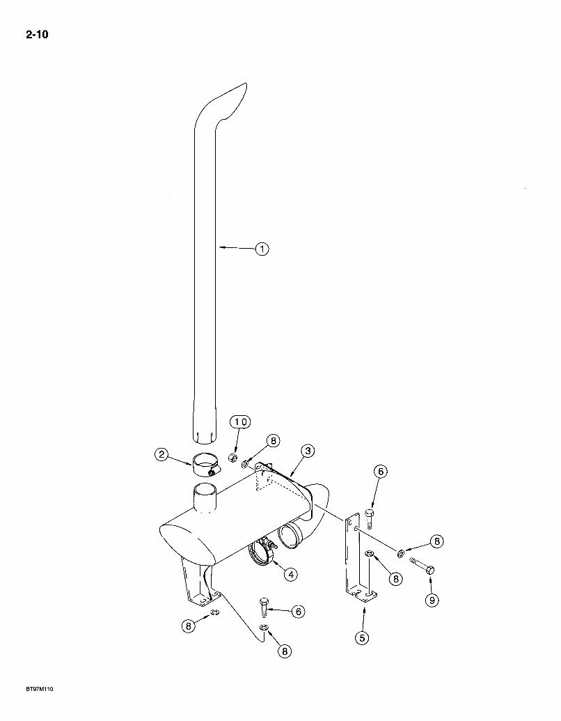
580 Super L Series 2 Loader Backhoe MUFFLER AND EXHAUST SYSTEM
2-11
REF. PART NO. 1 275967A1 2 176437A1 3 227293A1 4 A170467 5 225033A1 6 627-10030 8 896-11010 9 627-10030 10 829-1410
DESCRIPTION REQ'D. PIPE - exhaust, muffler extension CLAMP - exhaust pipe to muffler, includes hardware MUFFLER - engine exhaust CLAMP - includes hardware, muffler tube to engine BRACKET - muffler, front BOLT - hex, full threads, 10 -1.5 x 30 mm, class 10.9 4 WASHER - flat, 11 x 21 x 2.5 mm, hardened 10 BOLT - hex, full threads, 10 -1.5 x 30 mm, class 10.9 2 NUT - hex, 10 mm -1.5, class 10.9 2
Bur 7-3350 Issued February, 1998
2-12
D
i.:)
ROTATED 180°
®
4
BS97B262
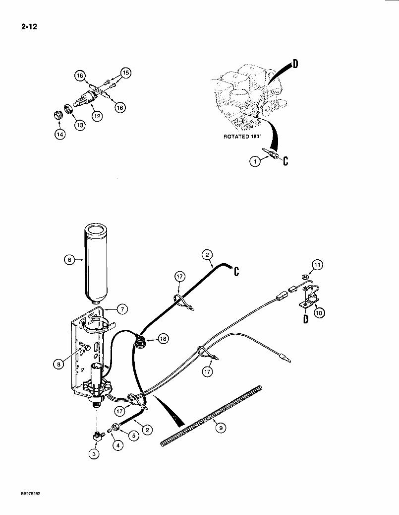
580 Super L Series 2 Loader Backhoe COLD START SYSTEM
2-13
REF. PART NO. 1 A189154
2 D145367
222-615 3 NSS 4 222-650. 5 222-660 6 A171940 7 A172116
8 276-24916 9 D128402 10 A187923
11 495-11034 L72776
12 NSS 13 H275784 14 D73741 15 174-93 16 L59682 17 LI 8337 18 254729A1
L60539X
DESCRIPTION REQ'D. NOZZLE ASSEMBLY - cold start injector, .008 dual orifice nozzle, component parts not serviced seperately 1 TUBE - 762 mm (30 inch) long, cut from L60539X bulk tube, valve to injector nozzle, see below 1 ELBOW - 90 degree, compression, 1/8 tube OD x 1/8 inch PT 1
BODY-elbow. 1 SLEEVE - tapered, 1/8 inch tube OD 1 NUT - hex, 1/8 tube OD x 5/16-24 inch 1
CYLINDER - starting fluid, ether 1 VALVE ASSEMBLY - cold start, 3 cc, starting fluid injection, component parts not serviced separately, mounts to inner left-hand chassis upright 1 SCREW - self-tapping, hex head, 3/8 NC x 1 inch 2 SLEEVE - wire guard, 380 mm (15 inch) long 1 SWITCH - temperature, circuit breaking, includes lead wires, uses existing intake manifold mounting hardware 1 WASHER-flat, 11/32 x 11/16 x 1/16 inch J .1 SWITCH ASSEMBLY - push button, cold start, must also order (2) L59682 blade terminals (item 16) 1
SWITCH - cold start . . : . .1 NUT - hex, special .1 NUT - hex, special 1 SCREW - machine, round head slotted, No. 10 NF x 174 inch 2
TERMINAL - blade, straight, use with L72776 switch 2 STRAP - tie, 15 inch, nylon . . UAR KIT - cap and cord, 1 inch threaded cap 1
TUBE - bulk, nylon, 3 (1/8) ID x 4267 mm (168 inch) long 1
Bur 7-3350 Issued February, 1998
2-14
a,
• » * • . • . • ' •••••• >/,
'.;r ^ .„;. --
® — ®
is)
B9408140S
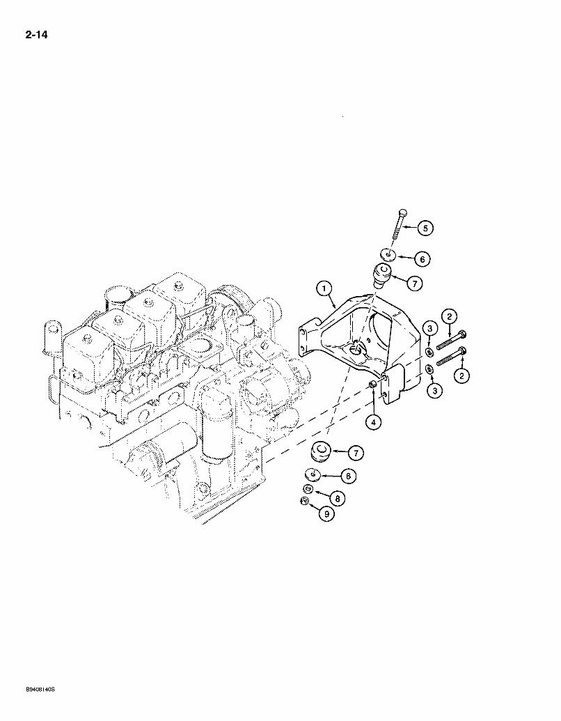
580 Super L Series 2 Loader Backhoe ENGINE MOUNTING
2-15
REF. PART NO. DESCRIPTION REQ'D. 1 175637A1 SUPPORT - engine, front 1 2 814-12110 BOLT -hex, 12 -1.75 X 110 mm 4 3 896-15012 WASHER - flat, 13.5 x 28 x 4 mm, hardened 4 4 A170309 SPACER - engine mount, upper bolt holes 2 5 814-12085 BOLT-hex, 12- 1.75x85 mm 2 6 496-81018 WASHER - flat, 33/64 x 2 x 1/8 inch, hardened 4 7 117844A1 INSULATOR - engine mount, front 2 8 896-15012 WASHER-flat, 13.5x28 X 4 mm, hardened 2 9 832-10412 NUT-hex, self-locking, 12 mm-1.75. . . . . 2
NOTE: See page 6-21 for rear engine/transmission mounts.
Bur 7-3350 Issued February, 1998
2-16
BT95G007

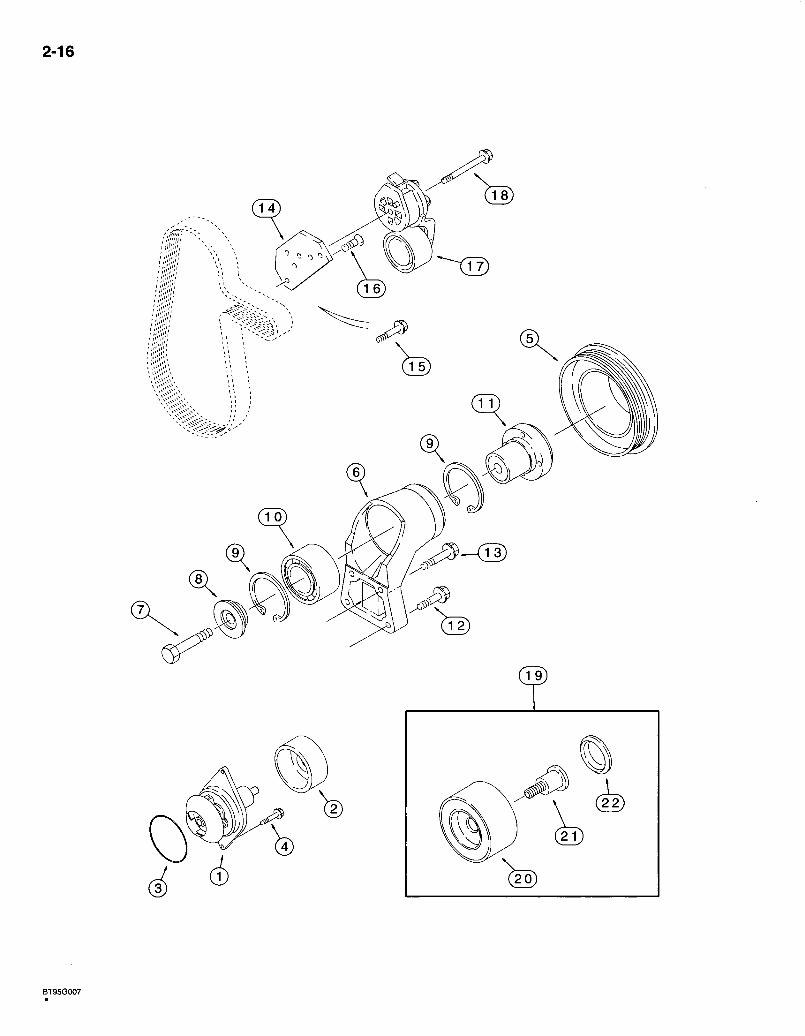
580 Super L Series 2 Loader Backhoe WATER PUMP SYSTEM
4T-390 ElVIISSIONS CERTIFIED ENGINE
2-17
REF. PART NO. J802358
1 NSS 2 NSS 3 238-5341 4 J900227 5 J914462 6 J911205 7 J907769 8 J923044 9 100-21250 10 J910739 11 J911924 12 845-8040 13 845-8030 14 J925195 15 845-8025 16 . J925186 17 J918944 18 854-10070 19 A77817
20 NSS 21 NSS 22 NSS
DESCRIPTION KIT - water pump
PUMP ASSEMBLY - water PULLEY - water pump 0-RING - 3-1/2 ID X 3/16 inch wide
BOLT - hex, special, 8 - 1.25 x 22 mm PULLEY-fan, 1.1 to 1 ratio SUPPORT - fan.
BOLT - hex, special, 10 -1.5 x 70 mm, class 12.9 RETAINER - fan hub RING - internal retaining, No. 250 BEARING-ball HUB - fan
BOLT - heavy hex flange, 8 - 1.25 x 40 mm BOLT - heavy hex flange, 8 - 1.25 x 30 mm BRACKET - belt tensioner. . BOLT - heavy hex flange, 8 - 1.25 x 25 mm SCREW - flat head cap, torx, special, 8 - 1.25 x 25 mm . . TENSIONER - belt BOLT - heavy hex flange, 10 -1.5 x 70 mm, class 10.9 KIT - belt tensioner pulley, used to replace pulley of J918944 belt tensioner, item 17
PULLEY- belt tensioner BOLT - pulley SEAL - dust
REQ'D.
Bur 7-3350 Issued February, 1998
2-18
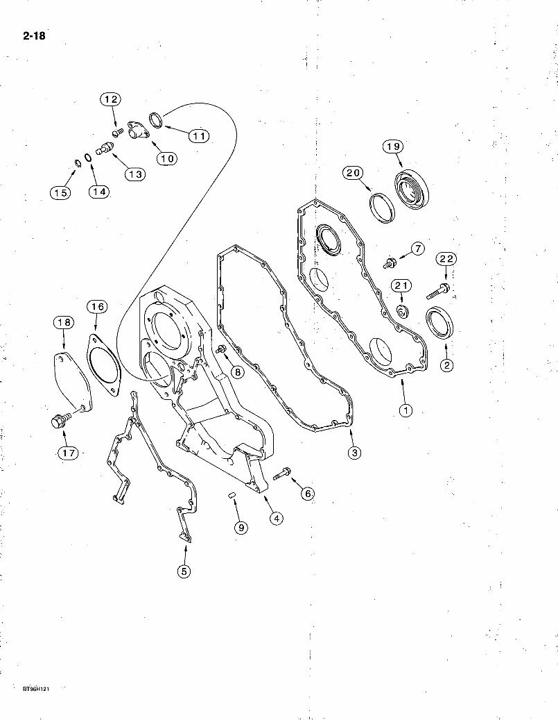
580 Super L Series 2 Loader Backhoe FRONT GEAR COVER
4T-390 EMISSIONS CERTIFIED ENGINE
REF. PART NO. 1 J918675 2 NSS 3 J918673 4 J932120 5 J931351 6 845-8050 7 J924962
8 J924962
9 J900257 10 J919683 11 J915772 12 J907998 13 J903924 14 J913994 15 J904849 16 J929751 17 854-12025 18 J914868 19 J903463 20 J903475 21 J912772 22 845-8060
2-19
REQ'D. DESCRIPTION COVER - gear, front SEAL - oil, crankcase front, order A77889 seal kit on page 2-43 . . . . GASKET - front cover HOUSING - timing gear GASKET - gear housing BOLT - heavy hex flange, 8 -1.25 x 50 mm 10 BOLT - hex flange, special, 8 -1.25 x 16 mm, external, retains item 1 to item 4 8 BOLT - hex flange, special, 8 - 1.25 x 16 mm, internal, retains item 4 to block 5 PIN - dowel, 16 mm long, locating 2 HOUSING - timing pin RING - quad, timing pin housing SCREW - round head cap, torx, special, 5 - 0.8 x 17 mm PIN - timing O-RING - sealing RING - retaining, timing pin : GASKET - access cover plate BOLT - heavy hex flange, 12 - 1.75 x 25 mm, class 10.9 PLATE - access cover, flat COVER - front access, fuel pump drive gear SEAL - front access cover, fuel pump drive gear RETAINER - bolt BOLT - heavy hex flange, 8 - 1.25 x 60 mm
Bur 7-3350 Issued February, 1998
2-20
BS96H021
REF.-
1 2 3
4 5 6 7 8
PART NO.
J901919 J905443 854-10065
A77416
J904339 J907185 J906773 J918109 J931605
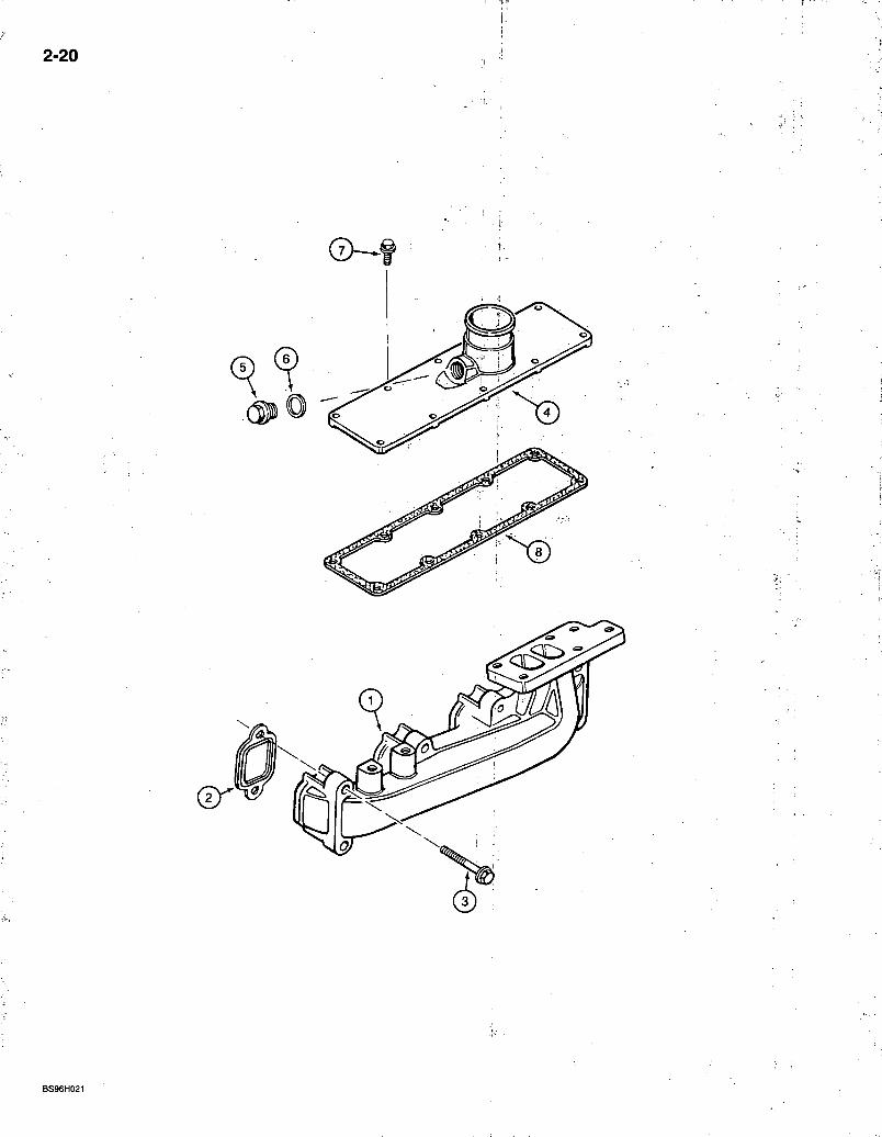
580 Super L Series 2 Loader Backhoe 2-21 MANIFOLDS
4T-390 EMISSIONS CERTIFIED ENGINE
DESCRIPTION REQ'D.
EXHAUST
MANIFOLD - exhaust • • .1 GASKET - exhaust manifold 4
BOLT - heavy hex flange, 10 - 1.50 x 65 mm, class 10.9 .8
INTAKE
KIT - intake manifold, no longer available, order components separately, items 4 - 6 1
COVER-intake .1 PLUG - manifold 1 WASHER-plug sealing . . . 1
BOLT - hex flange, special, 8 -1.25 x 25 mm, intake manifold 10 GASKET - intake manifold 1
Bur 7-3350 Issued February, 1998
2-22
BT96H075
580 Super L Series 2 Loader Backhoe TURBOGHARGER SYSTEM
4T-390 EMISSIONS CERTIFIED ENGINE
2-23
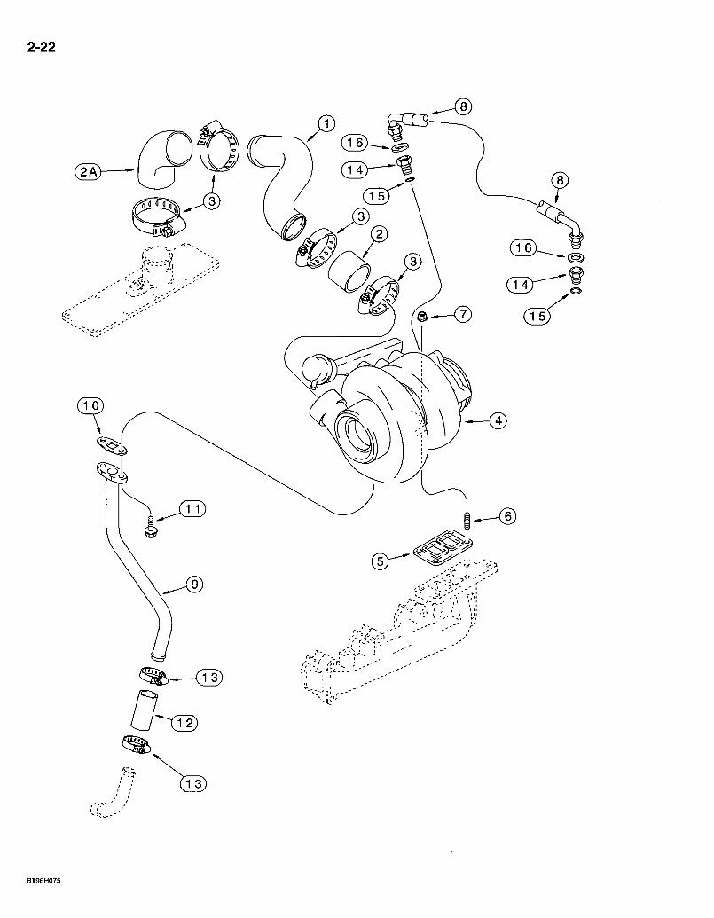
REF. P A R T NO. 1 J 9 3 1 7 8 4 2 J 9 3 1 8 0 4 2 A J 9 3 3 0 2 6 3 214 -3240 4 ' R E F
5 J 9 1 9 3 6 9 6 J 8 1 8 8 2 3 7 J 8 1 8 8 2 4 8 . J 9 1 3 7 5 9 9 J 9 0 3 7 4 0 1 0 , J 9 3 1 3 5 0 1 1 ' 8 4 5 - 8 0 2 0 1 2 J 9 3 1 9 7 0 1 3 2 1 4 - 1 4 1 6 1 4 J 9 1 9 6 8 7
1 5 2 3 8 - 5 0 1 3 1 6 222 -993
D E S C R I P T I O N R E Q ' D . T U B E - crossover 1 H O S E - 58 mm (2-1/4 inch) long, air intake .1 H O S E - 76 mm (3 inch) long, air intake 1 C L A M P - adj, 1 -3/4 - 2-5/8 inch dia 4 T U R B O C H A R G E R A S S E M B L Y - engine, new, see page 2 -25 for correct assembly and component parts 1 G A S K E T - tiirbocharger to manifold S T U D - turbocharger mounting 1 N U T - hex flange, special, 1 0 mm - 1 . 5 , stud 4 H O S E - turbocharger oil supply -1 T U B E - turbocharger oil drain 1 G A S K E T - turbo oil drain tube .1 B O L T - heavy hex flange, 8 - 1.25 x 2 0 mm . . .2 H O S E - 76 mm (3 inch) long, turbocharger oil drain 1 C L A M P - adj, 1 3 / 1 6 - 1 - 1 / 2 inch dia, hose: . \ . . . . . . 2 A D A P T E R - female hex, special ( 1 ) used to connect turbocharger oil supply hose to turbocharger, (1 ) used to connect turbocharger oil supply hose to J 9 1 8 9 5 4 oil filter head 2
O - R I N G - 7 / 1 6 ID X 1 /16 inch wide. .1 G A S K E T - flare, copper, 3/8 inch tube O D . . . 2
Bur 7 -3350 Issued February, 1998
2-24
580 Super L Series 2 Loader Backhoe 2-25 TURBOCHARGER ASSEMBLY
4T-390 EMISSIONS CERTIFIED ENGINE
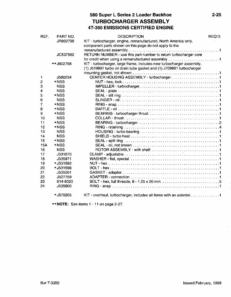
REF. PART NO. DESCRIPTION REQ'D. JR802798 KIT - turbocharger, engine, remanufactured. North America only,
component parts shown on this page do not apply to the remanufactured assembly 1
JC537562 RETURN NUMBER - use this part number to return turbocharger core for credit when using a remanufactured assembly 1
* * J802798 KIT - turbocharger, large frame, includes new turbocharger assembly, (1) J519807 turbo oil drain tube gasket and (1) J709861 turbocharger mounting gasket, not shown 1
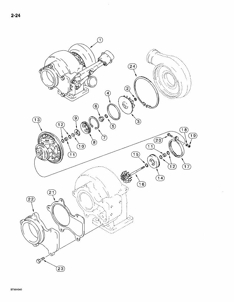
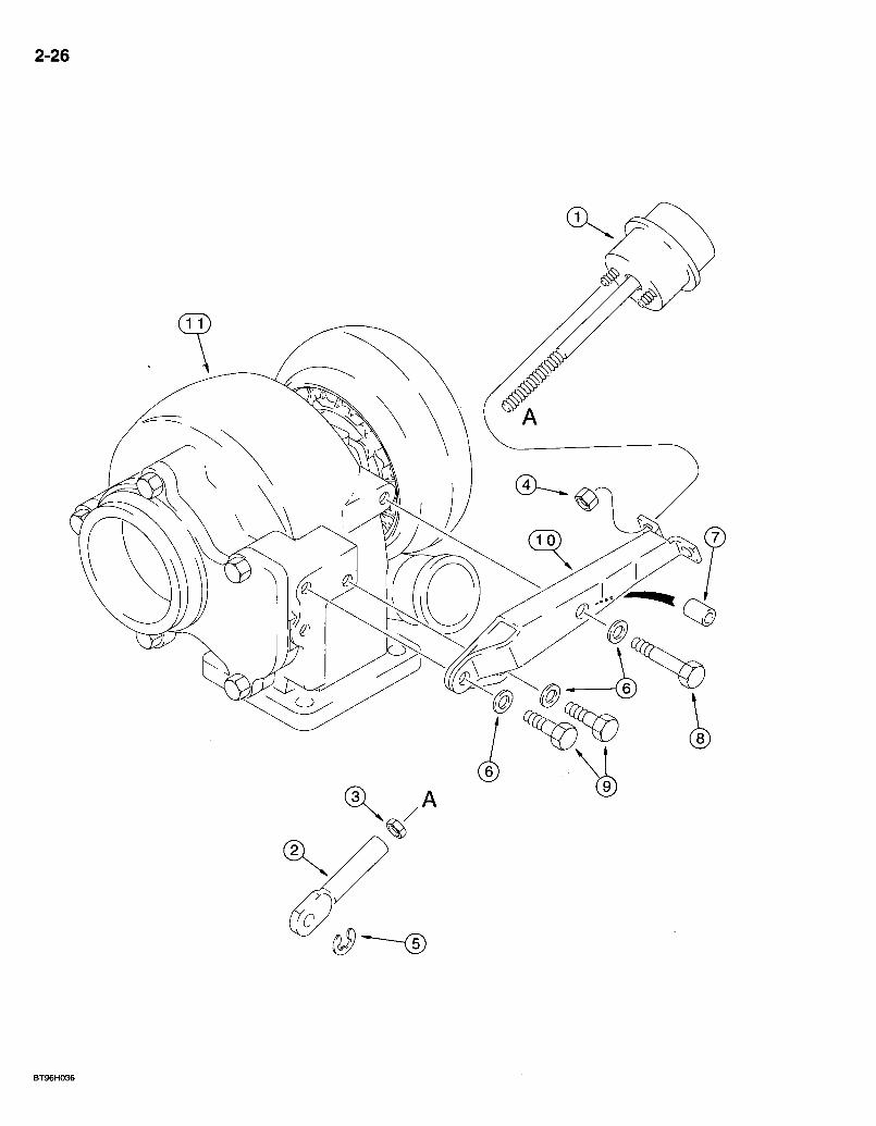
1 J580234 CENTER HOUSING ASSEMBLY - turbocharger 1 2 *NSS NUT-hex, lock 1 3 NSS IMPELLER - turbocharger 1 4 NSS SEAL-plate 1 5 *NSS SEAL - slit ring 1 6 NSS SLINGER-oil 1 7 *NSS RING-snap 1 8 *NSS BAFFLE-oil 1 9 *NSS BEARING - turbocharger thrust 1 10 NSS COLLAR - thrust 1 11 *NSS BEARING - turbocharger 2 12 *NSS RING - retaining 4 13 NSS HOUSING - turbo bearing 1 14 NSS SHIELD - turbo heat 1 15 *NSS SEAL - split ring 1 15A * NSS SEAL - oil, not shown 1 16 NSS ROTOR ASSEMBLY - with shaft 1 17 J531670 CLAMP - adjustable 1 18 J535971 WASHER - flat, special 1 19 *J531582 NUT-hex 1 20 *J531598 BOLT-hex 1 21 J535001 GASKET - adapter 1 22 J527759 ADAPTER - connection 1 23 614-8020 BOLT - hex, full threads, 8 - 1.25 x 20 mm 5 24 J535800 RING - snap 1
* J575205 KIT - overhaul, turbocharger, includes all items with an asterisk 1
* * NOTE: See items 1 -11 on page 2-27.
Bur 7-3350 Issued February, 1998
2-26
580 Super L Series 2 Loader Backhoe WASTEGATE ACTUATOR
4T-390 EMISSIONS CERTIFIED ENGINE
2-27
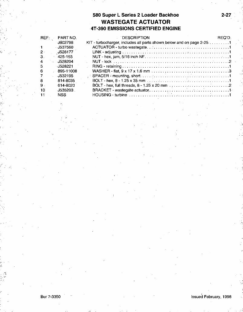
REF. PART NO. DESCRIPTION REQ'D. J802798 KIT - turbocharger, includes all parts shown below and on page 2-25 1
1 J537560 ACTUATOR - turbo wastegate. . 1 2 .J528177 LINK - adjusting 1 3 425-155 NUT-hex , jam, 5/16 inch NF • •-1 4 J528204 NUT - lock 2 5 J528221 RING - retaining • • -1 6 895-11008 WASHER-f la t , 9 x 1 7 x 1 . 6 m m 3 7 J532195 SPACER - mounting, short • • •I 8 814-8035 BOLT - hex, 8 - 1.25 x 35 mm . . . . . 1 9 614-8020 BOLT - hex, full threads, 8 - 1.25 X 20 mm . 2 10 J535203 BRACKET - wastegate actuator 1 11 NSS HOUSING - turbine 1
Bur 7-3350 Issued February, 1998
2-28
B9311042S
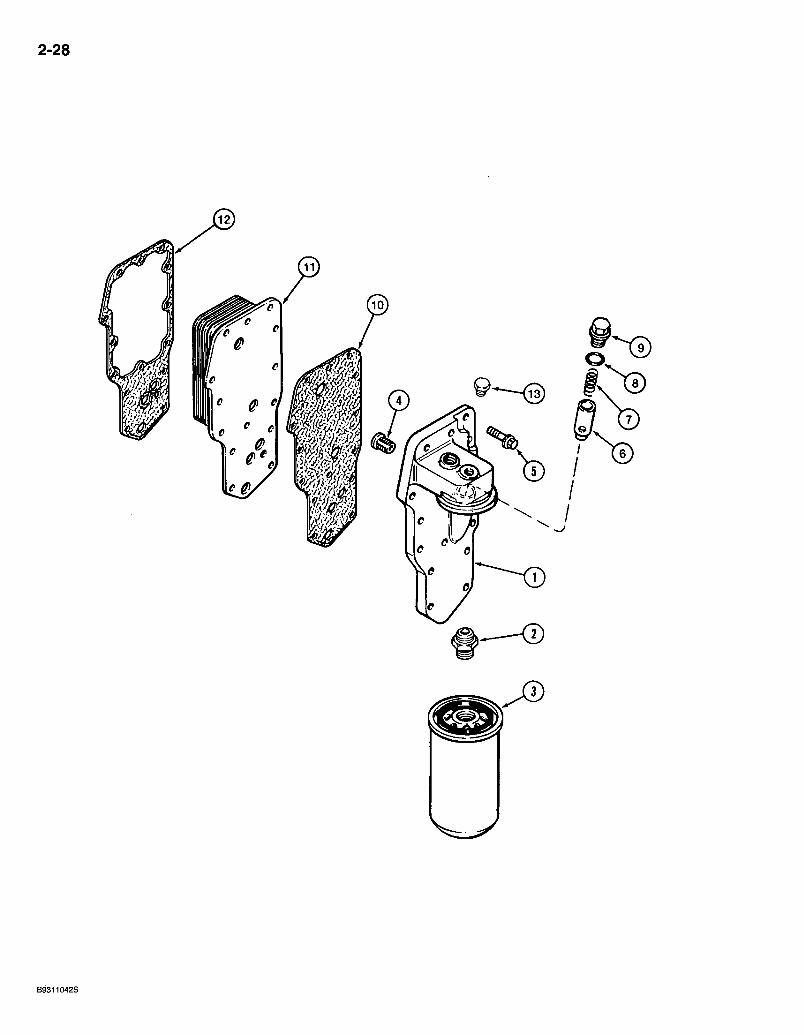
REF. PART NO. J918954
1 NSS 2 J909355 3 J908616 3 J934429 4 J927622 5 845-8035 6 J918428 7 J925G09 8 J929457 9 J915787 10 J929792 11 J921557 12 J942914 13 J906619
580 Super L Series 2 Loader Backhoe OIL FILTER AND COOLER
4T-390 EMISSIONS CERTIFIED ENGINE
2-29
REQ'D. DESCRIPTION HEAD ASSEMBLY - oil filter and cooler
HEAD- lube oilfi l ler ADAPTER - filter head
FILTER - engine oil, cartridge, if used FILTER - engine oil, cartridge, premium oil filter, if used VALVE - relief, pressure BOLT - heavy hex flange, 8 - 1.25 x 35 mm 14 PLUNGER - regulator, pressure SPRING - compression 0 -R ING-p lug PLUG - threaded, pipe GASKET - filter head CORE - cooler, oil GASKET - oil cooler core PLUG-hex , 1/8 inch PT
Bur 7-3350 Issued February, 1998

2-30
REF. PART NO. JR930336
JG926202
1 , J930336 2 J900677 3 J905206 4 *J931349 5 845-8016 6 J901049 7 ; *NSS 8 J924147 9 *J920773 10 J920400 11 J924148 12 **J902425
*A77673
* *A77490 13 NSS 14 196466A1
580 Super L Series 2 Loader Backhoe OIL PUMP AND OIL PAN
4T-390 EMISSIONS CERTIFIED ENGINE
2-31
DESCRIPTION REQ'D. PUMP - oil, remanufactured, North America only, component parts shown on this page do not apply to the remanufactured assembly. 1 RETURN NUMBER - use this part number to return pump core for credit when using a remanufactured a s s e m b l y . . . . PUMP - oil, engine, new BOLT - hex, full threads, 8 - 1.25 x 30 mm TUBE - suction, oil GASKET - mounting, oil suction .tube . ) BOLT - heavy hex flange, 8 -1:25 x 16 mrh PAN - oil, engine GASKET - oil pan, order A77673 gasket kit for service. PLUG - hex magnetic, special, 12 mm -1 .5 , drain, oil WASHER - sealing, drain plug. . SCREW - hex flange cap, special, 8 - 1.25 x 25 mm 28 PLUG - hex magnetic, special, 22 mm -1 .5 , pipe, heater hole WASHER - sealing, plug
KIT - gasket, oil pan, includes all items shown above with an asterisk 1
ENGINE OIL HEATER
KIT - heater, engine oil .1 ELEMENT - heater, 120 volt 1 CABLE - engine block heater 1
* * NOTE: When engine oil heater kit is ordered, item 12, J902425 washer must also be ordered.
Bur 7-3350 Issued February, 1998
2-32
580 Super L Series 2 Loader Backhoe CYLINDER HEAD C O V E R S
4T-390 EMISSIONS CERTIFIED ENGINE
2-33
REF. PART N O . 1 , REF 2 J283333 2 J283336 2 J283338 3 J928404 4 J930906 5 J928406 6 . "J907049 7 '^v ' J908 i18. 8 . '854-12030
9 J9b3757 10 J914409
A77736 11 - J923331 12 • N S S 13 845-8070 14 845-8035 15 J923387 16 845-8025
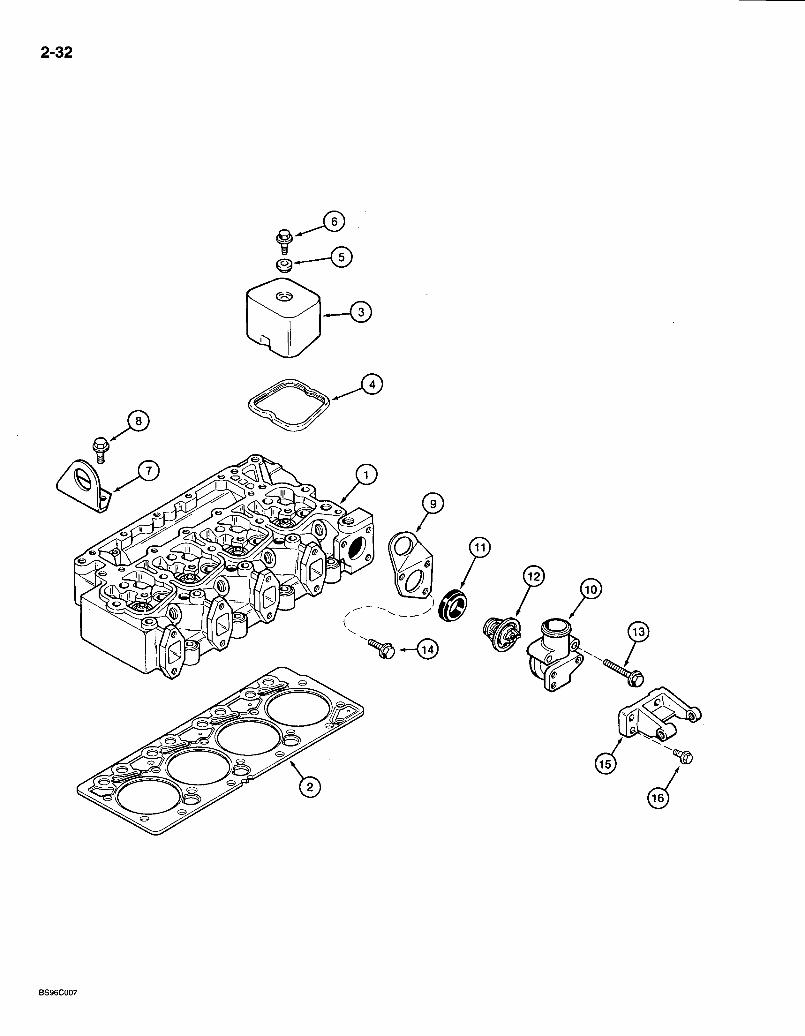
D E S C R I P T I O N . R E Q ' D . H E A D - cylinder, see page 2-35 for correct cylinder head; and parts l i s t . . . . . . . A-G A S K E T - head, standard 1 G A S K E T - head, 2 notches, 0.25 mm overthick 1 G A S K E T - head, 3 notches, 0.^0 mm overthick 1 C O V E R - rocker arm 4 S E A L - rocker arm cover 4 I S O L A T O R - noise 4 B O L T - hex flange, special, 8 - 1.25 x 21.25 mm 4 B R A C K E T - lifting, rear 1 B O L T : - heavy hex flange, 1 2 - 1.75 x 30 mm, class 10.9 . . . . . . . . . . .2
THERMOSTAT AND HOUSING
B R A C K E T - lifting, front 1 H O U S I N G - thermostat . . : : : 1 1 K I T - coolant thermostat . . . 1
G A S K E T - therrriostat housing 1 T H E R M O S T A T - coolant -1
B O L T - heavy hex flange, 8 - 1.25 x 70 mm 2 B O L T - heavy hex flange, 8 - 1.25 x 35 mm 1 S U P P O R T - alternator mounting 1 B O L T - heavy hex flange, 8 - 1.25 x 25 mm 3
Bur 7-3350 Issued February, 1998
2-34
BT96H022
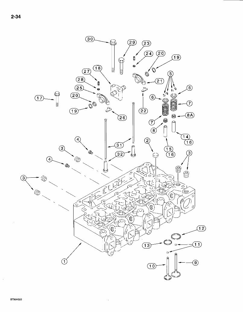
580 Super L Series 2 Loader Backhoe CYLINDER HEAD AND VALVE MECHANISM
4T-390 EMISSIONS CERTIFIED ENGINE
2-35
REF. PART'NO. JR927330
JC927330
DESCRIPTION REQ'D. HEAD ASSEMBLY - cylinder, remanufactured, North America only, component parts shown on this page do not apply to the remanufactured assembly 1 RETURN NUMBER - use this part number to return head for credit when using a remanufactured assembly 1 HEAD ASSEMBLY - cylinder, new, with valves. . 1
HEAD ASSEMBLY - cylinder, new,- without valves 1 PLUG - expansion, 21 mm OD 3
. PLUG - square socket headless, 1/2 inch PT, one removedjto install temperature sending unit . .5 PLUG-hex , 1/8 inch PT '. 2 KEEPER- valve 16 RETAINER - valve spring 8 SPRING-valve . . . 8 SEAL - valve stem . A
_ • SEAL - valve, intake -4 VALVE- intake • • -4 VALVE - exhaust 4
PAD - wear, service repair only for valve stem tip, for use on intake and exhaust valves UAR SEAT - insert, intake valve, service repair only 4 SEAT - insert, exhaust valve, service repair only 4 GUIDE - valve, intake, service repair only, 14 mm OD .4 GUIDE-vajve, exhaust, service repair only, 14r r imOD. . 4 GUIDE - valve, intake and exhaust, service repair only, 11 mm O D . . . .8 BOLT - cylinder head, 70 mm long 4 BOLT - cylinder head, 120 mm long 10 SUPPORT AND SHAFT ASSEMBLY - rocker arm 4 RING - retaining, rocker arm 8 WASHER - thrust, rocker arm .8 ARM ASSEMBLY - rocker, intake 4
INSERT - rocker arm 1 SCREW - slotted set, adjusting, special 1 NUT-hex , 3/8 inch NF 1
ARM ASSEMBLY - rocker, exhaust 4 INSERT - rocker arm . . 1 . SCREW - slotted set, adjusting, special 1 NUT-hex , 3/8 inch NF 1
BOLT - hex, 8 - 1.25 x 75 mm . . .4 BOLT - rocker arm and bylinder head, 180 mm long; 4 ROD - push, rocker arm. 8 TAPPET - valve, push rod 8
• N O T E : These parts are semi-finished valve guides.
1 „ J927330 1 J917433 2 A77783 3 217-466
4 . ..J906619^ J900250
6 "•' J900299 -7 J926700 8 J90i097 8A J921640 9 ; , J920867 10 J920868 n J280911
12 J906854 13 J904105 14 *J904408 15 *J904409 16 *J9062p6 17 J9207t9 17 J920780 18 J922488 19 J900242 20 J900245 21 J910811 22 NSS 23 . J900706 24 425-116 25 J910810 26 NSS 27 J900706 28 425-116 29 814-8075 30 J920781 31 J923262 32 J931623
Bur 7-3350 Issued February, 1998
2-36
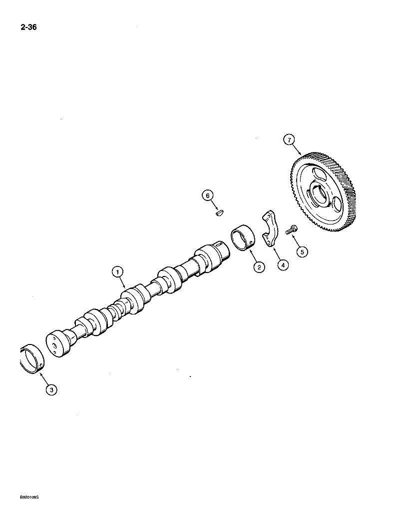
REF. PARTNO. 1 J929885 2 J940059 . 3 *J903242 4 J927155 5 J900227 6 836-4065 7 J929028
580 Super L Series 2 Loader Backhoe 2-37 CAMSHAFT
4T-390 EMISSIONS CERTIFIED ENGINE
DESCRIPTION REQ'D. CAMSHAFT - engine 1 BUSHING - camshaft, front. 1 BUSHING - camshaft, intermediate and rear, service repair only 4 SUPPORT - thrust, camshaft. . . 1 BOLT - hex, special, 8 - 1.25 x 22 mm .2 KEY - Woodruff, 4 x 6.5 mm, camshaft gear . .1 GEAR - camshaft. 1
• N O T E : When the-intermediate and rear cylinder block camshaft bores are reamed in engine repair, order and install iterfi 3, J9G3242 bushings shown above.
Bur 7-3350 Issued February, 1998

2-38
CD
0 a
BS97K164
REF.
1
2 3 4 5 6 6A 7 8
9 10 11 12 12A
13 14 15 16 16A 17 17A 17B 17C 17D 17E
580 Super L Series 2 Loader Backhoe CYLINDER BLOCK
4T-390 EMISSIONS CERTIFIED ENGINE
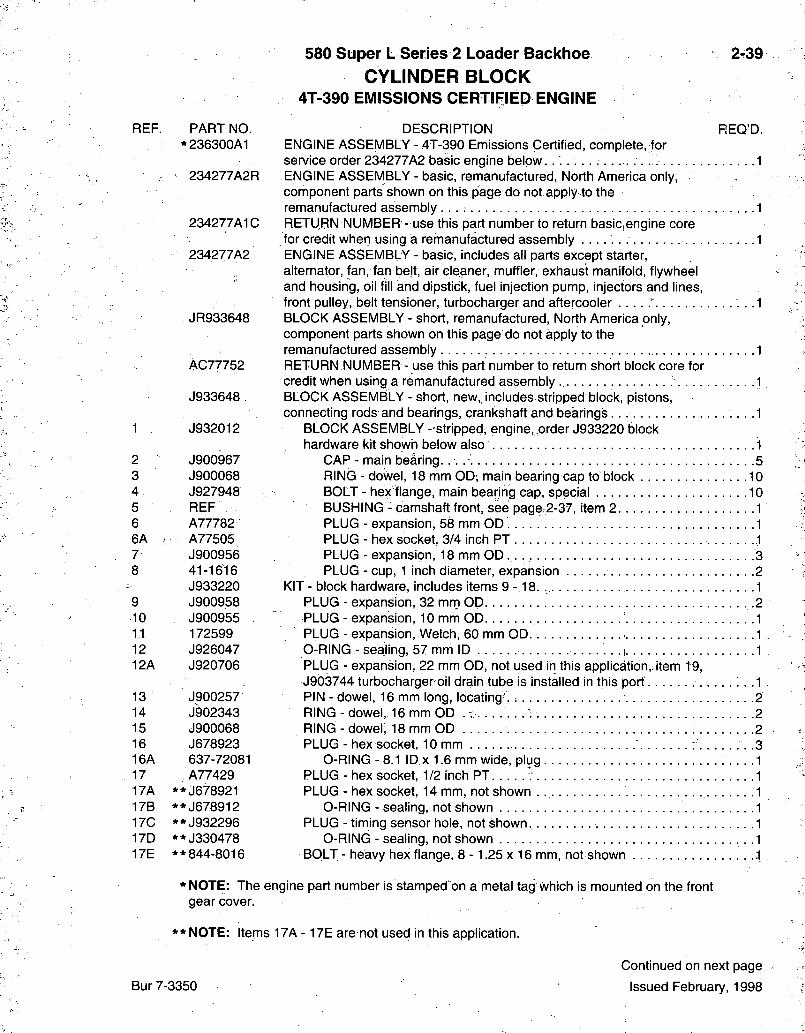
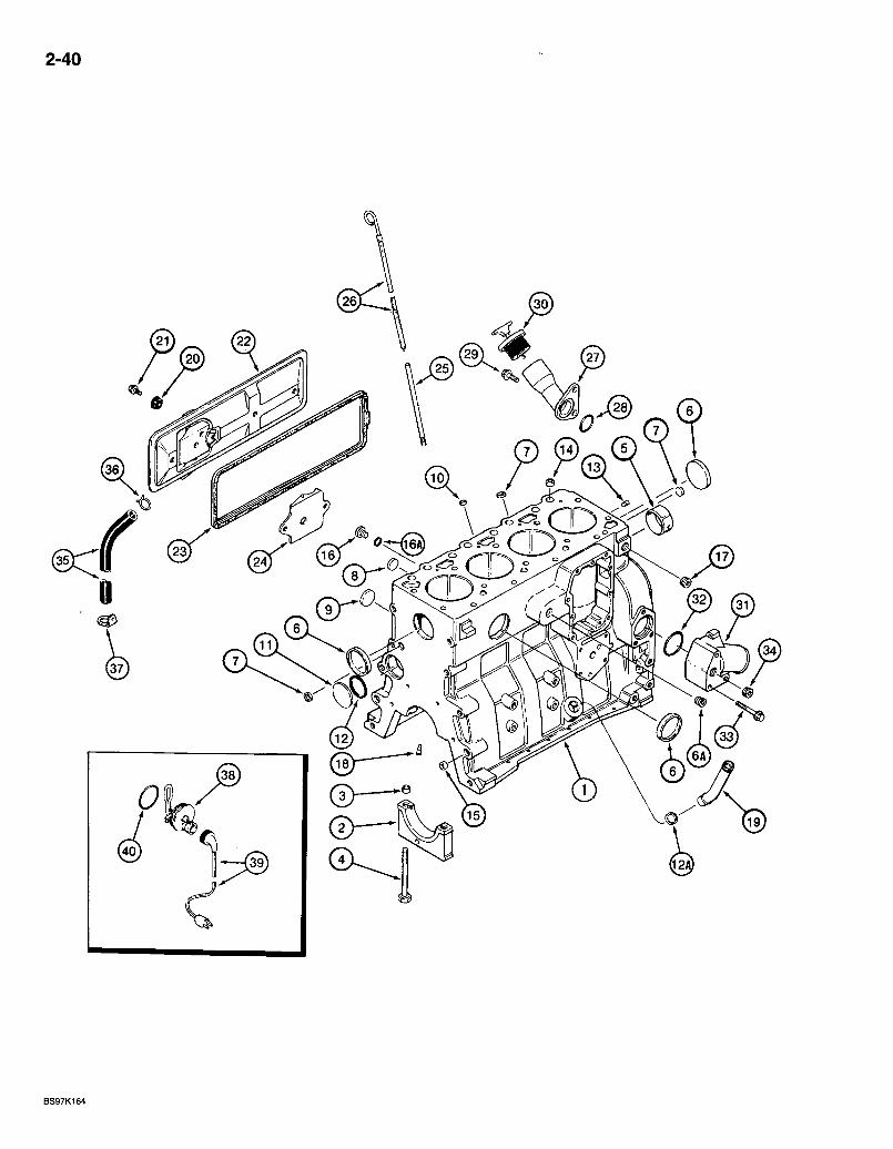
2.39
PART NO. DESCRIPTION REQ'D. *236300A1 ENGINE ASSEMBLY - 4T-39G Emissions Certified, complete, for
service order 234277A2 basic engine b e l o w . . . 1 234277A2R ENGINE ASSEMBLY - basic, remanufactured. North America only,
component parts shown on this page do not apply to the remanufactured assembly 1
234277A1C RETURN NUMBER - use this part number to return basic engine core for credit when using a remanufactured assembly 1
234277A2 ENGINE ASSEMBLY - basic, includes all parts except starter, alternator, fan, fan belt, air Gleaner, muffler, exhaust manifold, flywheel and housing, oil fill and dipstick, fuel injection pump, injectors and lines, front pulley, belt tensioner, turbocharger and aftercooler ' . .1
JR933648 BLOCK ASSEMBLY - short, remanufactured. North America only, component parts shown on this page do not apply to the remanufactured assembly 1
AC77752 RETURN NUMBER - use this part number to return short block core for credit when using a remanufactured assembly ., 1
J933648 BLOCK ASSEMBLY-short , new, includes stripped block,, pistons, connecting rods and bearings, crankshaft and bearings .1
J932012 BLOCK ASSEMBLY-str ipped, engine, order J933220'block hardware kit showh below also 1
J900967 CAP - main bearing. 5 J900068 RING - dowel, 18 mm OD, main bearing cap to block 10 J927948 BOLT - hex flange, main bearing cap, special . . . .j 10 REF BUSHING - camshaft front, see page.2-37, item 2 1 A77782 • PLUG - expansion, 58 mm OD 1 A77505 PLUG - hex socket, 3/4 inch PT 1 J900956 PLUG - expansion, 18 mm O D . . 3 41-1616 PLUG - cup, 1 inch diameter, expansion . 2 J933220 KIT - block hardware, includes items 9 - 1 8 . , 1 J900958 PLUG - expansion, 32 mrri OD 2 J900955 PLUG - expansion, 10 mm OD 1 172599 PLUG - expansion, Welch, 60 mm OD 1 J926047 O-RING - sealing, 57 mm ID . . i 1 J920706 PLUG - expansion, 22 mm OD, not used in this application,; item 19,
J9d3744 turbocharger oil drain tube is installed in this port . .1 J900257 PIN - dowel, 16 mm long, locating . : 2 J902343 RING-dowel , 1 6 m m O D . T . . . . . . ; 2 J900068 RING - dowei; 18 mm OD 2 J678923 PLUG - hex socket, 10 mm 3 637-72081 O-RING-8.1 ID x 1.6 mm wide, plug 1 A77429 PLUG - hex socket, 1/2 inch PT v 1
* * J678921 PLUG - hex socket, 14 mm, not shown 1 * * J678912 O-RING - sealing, not shown 1 * * J932296 PLUG - timing sensor hole, not shown. 1 * * J330478 O-RING - sealing, not shown , . .1 **844-8016 BOLT - heavy hex flange, 8 - 1.25 x 16 mm, not shown 1
* NOTE: The engine part number is stamped'on a metal tag which is mounted on the front gear cover.
* * N O T E : Items 17A - 17E are not used in this application.
Bur 7-3350
Continued on next page
Issued February, 1998
2-40
0
580 Super L Series 2 Loader Backhoe CYLINDER BLOCK
4T-390 EMISSIONS CERTIFIED ENGINE
2-41
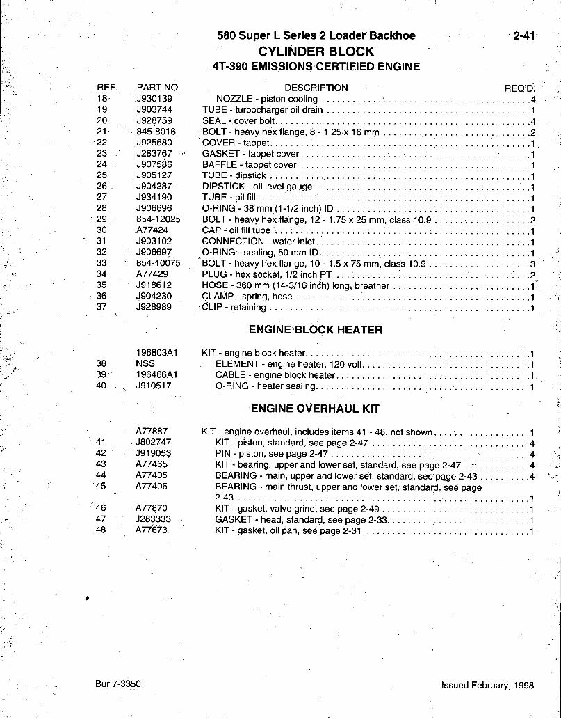
REF. PART NO. 18 J930139 19 J903744 20 J928759 21 845-8016 22 J925680 23 J283767 24 J907586 25 J905127 26 J904287 27 J934190 28 J906696 29 854-12025 30 A77424 31 J903102 32 J906697 33 854-10075 34 A77429 35 J918612 36 J904230 37 J928989
196803A1 38 NSS 39 196466A1 40 J910517
A77887 41 J802747 42 J919053 43 A77465 44 - A77405 45 A77406
46 A77870 47 J283333 48 A77'673.
DESCRIPTION REQ'D. NOZZLE - piston cooling 4
TUBE - turbocharger oil drain 1 SEAL- cover bolt 4
' BOLT - heavy hex flange, 8 -1.25 x 16 mm . 2 COVER-tappet . • . • • • -1 GASKET - tappet cover 1 BAFFLE - tappet cover 1 TUBE - dipstick 1 DIPSTICK - oil level gauge -1 T U B E - o i l fill 1 0-RING - 38 mhi (1-1/2 inch) ID : 1 BOLT - heavy hex fla:nge, 12 - 1.75 x 25 mm, class .10.9 . ; 2 C A P - oil fill tube \ . . . . . . .1 CONNECTION - water inlet. • . 1 0-RING - sealing, 50 mm ID 1
' BOLT - heavy hex flange, 10 -1 .5 x 75 mm, class 10.9 3 PLUG - hex socket, 1/2 inch PT • • . .2., HOSE - 360 mm (14-3/16 inch) long, breather 1 CLAMP - spring, hose .1 CiLIP - retaining 1
ENGINE BLOCK HEATER
KIT - engine block heater. 1 ELEMENT - engine heater, 120 volt .1 CABLE - engine block heater 1 O-RING - heater seal ing.. : 1
ENGINE OVERHAUL KIT
KIT - engine overhaul, includes items 41 - 48, not shown 1 KIT - piston, standard, see page 2-47 4 PIN - piston, see page 2-47 .4 KIT - bearing, upper and lower set, standard, see page 2-47 ..-. . . . . . . . . . . 4 BEARING - main, upper and lower set, standard, see page 2-43 . 4 BEARING - main thrust, upper and lower set, standard, see page 2-43 . • • 1 KIT - gasket, valve grind, see page 2-49 1 GASKET - head, standard, see page 2-33. 1 KIT - gasket, oil pan, see page 2-31 1
Bur 7-3350 Issued February, 1998
2-42
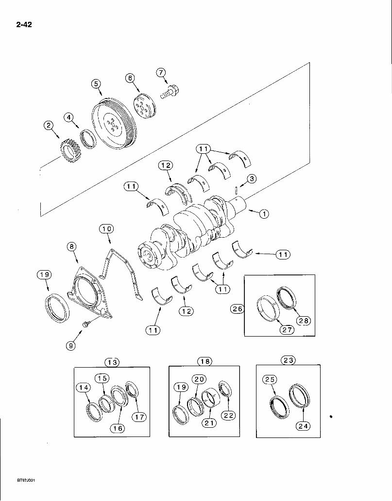
580 Super L Series 2 Loader Backhoe CRANKSHAFT
4T-390 EMISSIONS CERTIFIED ENGINE
REF. PART NO. JR908031
JC908031
1 J908031 2 J929027 3 J904483 4 NSS 5 J9 i4494 6 J905820 7 J903857 8 J921043 9 845-6015 10 J928493 11 A77405 11 / A77472 11 A77474 11 A77476 11 A77478 12 A77406 12 A77473 12 A77475 12 A77477 12 A77479 12 A77841;
12 A77840
13 A77889 14 NSS 15 NSS 16 NSS 17 NSS 18 A77890 19 NSS 20 NSS 21 NSS 22 NSS 23 A77809 24 NSS 25 NSS 26 A77810 27 NSS 28 NSS
2-43
REQ'D. DESCRIPTION CRANKSHAFT - engine, remanufactured, North America only, component parts shown on this page do not apply to the remanufactured assembly, for service order J908031 crankshaft assembly, item 1 RETURN NUMBER - use this part number to return crankshaft for credit when using a remanufactured assembly CRANKSHAFT ASSEMBLY - engine
GEAR - crankshaft P IN-dowel
SEAL - oil, crankshaft front, order item 13 kit PULLEY - crankshaft vibration damper FLANGE - adapter, pulley BOLT-hex flange, special, 1 2 - 1 .25x36 mm .; .4 RETAINER - seal, rear cover. . .1 BOLT - heavy hex flange, 6 - 1 .O x 15 mm 6 GASKET - rear cover retainer 1 BEARING - main, upper and lower set, standard 4 BEARING - main, uppenand lower set, 0.25 mm undersize 4 BEARING - main, upper and lower set, 0.50 mm undersize . .4 BEARING - main, upper and lower set, 0.75 mm undersize .4 BEARING - main,- upper and lower set, 1.00 mm undersize 4 BEARING - main thrust, upper and lower set, standard BEARING - main thrust, upper and lower set, 0.25 mm undersize . . . . BEARING - main thrust, upper and lower set, 0.50 mm undersize BEARING - main thrust, upper and lower set, 0.75 mm undersize BEARING - main-thrust, upper and lower set, 1.00 mm undersize . . . . BEARING - main thrust, upper and lower set, 0.50 mm undersize, 0.50 mrh oversize thrust / . BEARING - main thrust, upper and lower set, 1.00 mm undersize, 1.00 mm oversize thrust KIT - oil seal, crankshaft front
SEAL - oil, front TOOL - installation TOOL - installation SHIELD - dust
KIT - oil seal, crankshaft front, includes wear sleeve SEAL - oil, front SLEEVE - wear, not shown TOOL - installation SHIELD-dust
KIT - oil seal, crankshaft rear TOOL - installation SEAL - oil, rear
KIT - oil seal, crankshaft rear, includes wear sleeve i . . SLEEVE - wear ' SEAL-o i l , rear
Bur 7-3350 Issued February, 1998
2-44
B9501053S
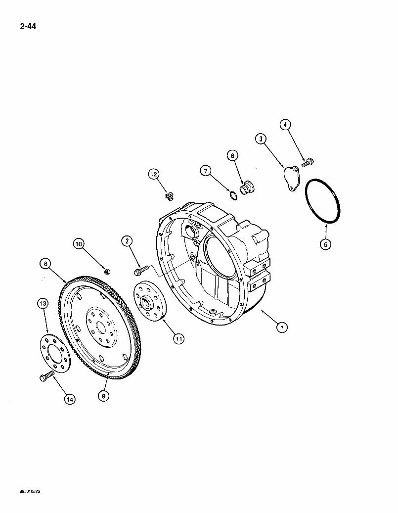
580 Super L Series 2 Loader Backhoe FLYWHEEL AND HOUSING
4T-390 EMISSIONS CERTIFIED ENGINE
2-45
REF. . PARTNO. 1 J930886 2 854-12040 3 J925234 4 613-8016 5 J912473 6 J910248 7 . 238-5212
J922595 8 NSS -9 NSS 10 NSS 11 J913689 12 353-225 13 J904361 14 J901395
DESCRIPTION REQ'D. HOUSING - flywheel 1 BOLT - heavy hex flange, 12 - 1.75 x 40 mm, class 10.9 .8 PLATE - cover • • BOLT - hex, 8 - 1 .25x16 mm, retaining plate. 2 0-RING - flywheel housing to block 1 PLUG - flywheel housing 1 0-RING - 7/8 ID X 1/8 inch wide, sealing 1 PLATE ASSEMBLY - flex .1
GEAR - ring, flywheel 1 PLATE-f lex 1 NUT - sealing • -6
ADAPTER - crankshaft 1 PLUG - slotted hex, 3/4 inch NF 1 RING - clamping .1 BOLT - hex, special, 12 - 1.25 x 32 mm .8
Bur 7-3350 Issued February, 1998
2-46
< 3 )
REF. PART NO.
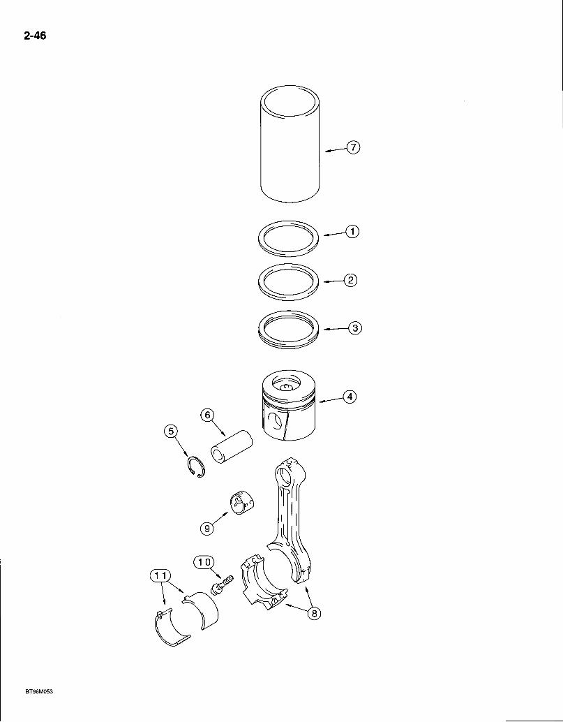
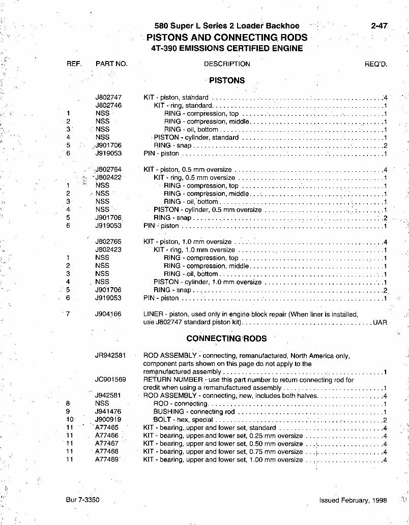
580 Super L Series 2 Loader Backhoe PISTONS AND CONNECTING RODS 4T-390 EMISSIONS CERTIFIED ENGINE
DESCRIPTION
PISTONS
2-47
REQ'D.
J802747 J802746
1 NSS 2 NSS 3 NSS 4 NSS 5 <J901706 6 J919053
^ J802764 h ••J802422
1 NSS 2 , NSS 3 NSS 4 NSS 5 J901706 6 J919053
J802765 J802423
1 NSS 2 NSS 3 NSS 4 . NSS 5 J901706 6 J919053
7 J904166
8 9
JR942581
JC901569
J942581 NSS J941476 J900919 A77465 A77466 . A77467 A77468 A77469
KIT - piston, standard 4 KIT - ring, standard .1
RING - compression, top .1 RING - compression, middle. 1 RING - oil, bottom 1
PISTON - cylinder, standard 1 RING - snap -2
PIN - piston 1
KIT - piston, 0.5 mm oversize 4 KIT - ring, 0.5 mm oversize 1
RING - compression, top 1 RING - compression,.middle... 1 RING - oil, bottom . . ' 1
PIStON - cylinder, 0.5 mm oversize .1 RING-snap . ..2
PIN - piston 1
KIT - piston, 1.0 mm oversize • .4 KIT - ring, 1.0 mm oversize 1
RING - compression, top .1 RING - compression, middle 1 RING - oil, bottom .1
PISTON - cylinder, 1.0 mm oversize • .1 R I N G - s n a p . . 2.
PIN - piston 1
LINER - piston, used only in engine blocl< repair (When liner is installed, use J802747 standard piston kit). UAR
CONNECTING RODS
ROD ASSEMBLY - connecting, remanufactured, North Anrierica only, component parts shown on this page do not apply to the remanufactured assembly 1 RETURN NUMBER - use this part number to return connecting rod for credit when using a remanufactured assembly . 1 ROD ASSEMBLY - connecting, new, includes both halves .4
ROD - connecting. 1 BUSHING - connecting rod 1 BOLT - hex, special .;. 2
KIT - bearing„upper and lower set, standard 4 KIT - bearing, upperrand lower set, 0.25 mm oversize 4 KIT - bearing, upper and lower set, 0.50 mm oversize . . .; 4 KIT - bearing, upper and lower set, 0.75 mm oversize 4 KIT-bear ing, upper and lower set, 1.00 mm oversize . . , 4
Bur 7-3350 Issued February, 1998
2-48
^3)
®
^5=
REF. PART NO.
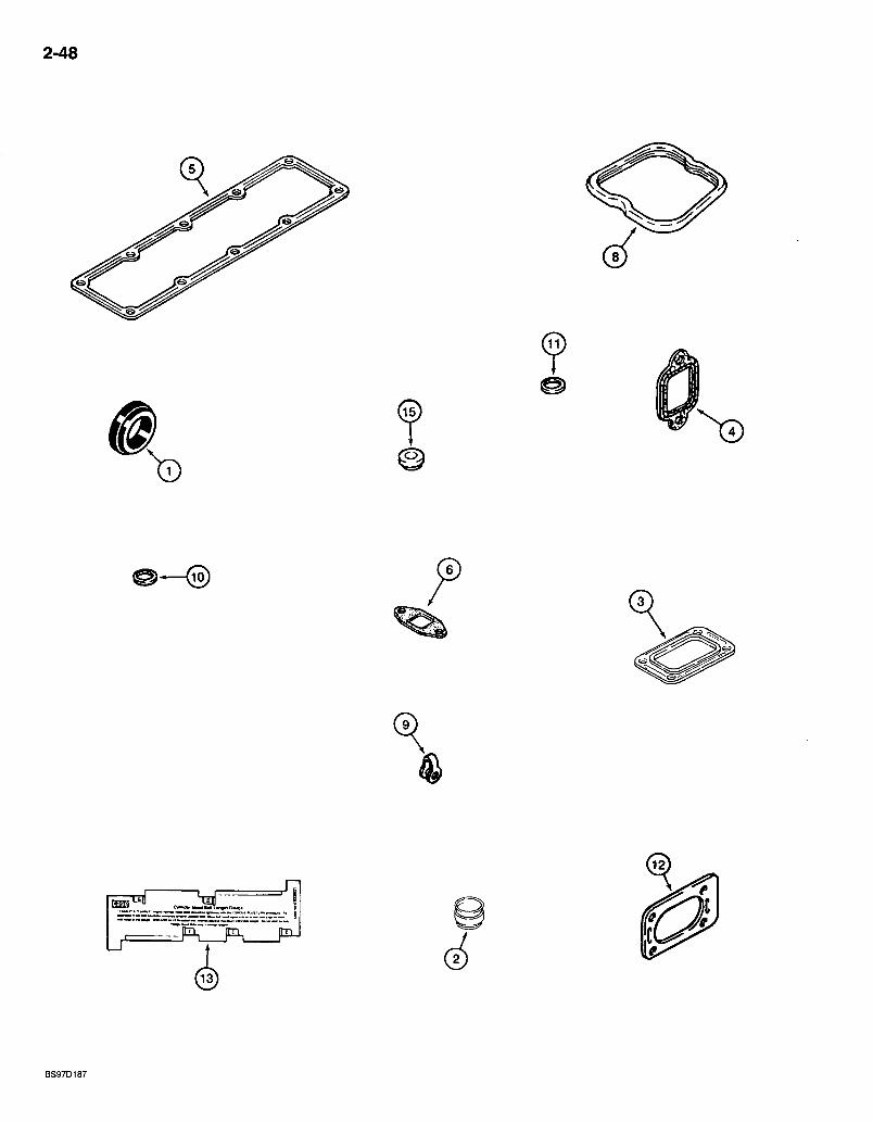
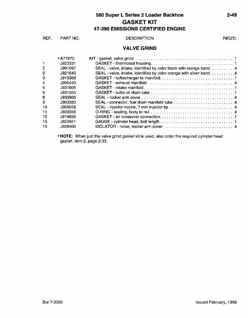
580 Super L Series 2 Loader Backhoe GASKET KIT
4T-390 EMISSIONS CERTIFIED ENGINE
DESCRIPTION
VALVE GRIND
2-49
REQ'D.
* A77870 KIT - gasket, valve grind 1 1 J923331 GASKET - thermostat housing 1 2 J901097 SEAL - valve, intake, identified by color black with orange band 4 2 J921640 SEAL - valve, intake, identified by color orange with silver band 4 3 J919369 GASKET - turbocharger to manifold 1 4 J905443 GASKET - exhaust manifold 4 5 J931605 GASKET - intake manifold 1 6 J931350 GASKET - turbo oil drain tube 1 8 J930906 SEAL - rocker arm cover 4 9 J903380 SEAL - connector, fuel drain manifold tube 4 10 J906659 SEAL - injector nozzle, 7 mm injector tip 4 11 J909356 0-RING - sealing, body to nut 4 12 J914856 GASKET - air crossover connection 1 13 J823921 GAUGE - cylinder head, bolt length 1 15 J928406 ISOLATOR - noise, rocker arm cover 4
* NOTE: When just the valve grind gasket kit is used, also order the required cylinder head gasket, item 2, page 2-33.
Bur 7-3350 Issued February, 1998
2-50
J ' ,
BT96H199
REF. PART NO.
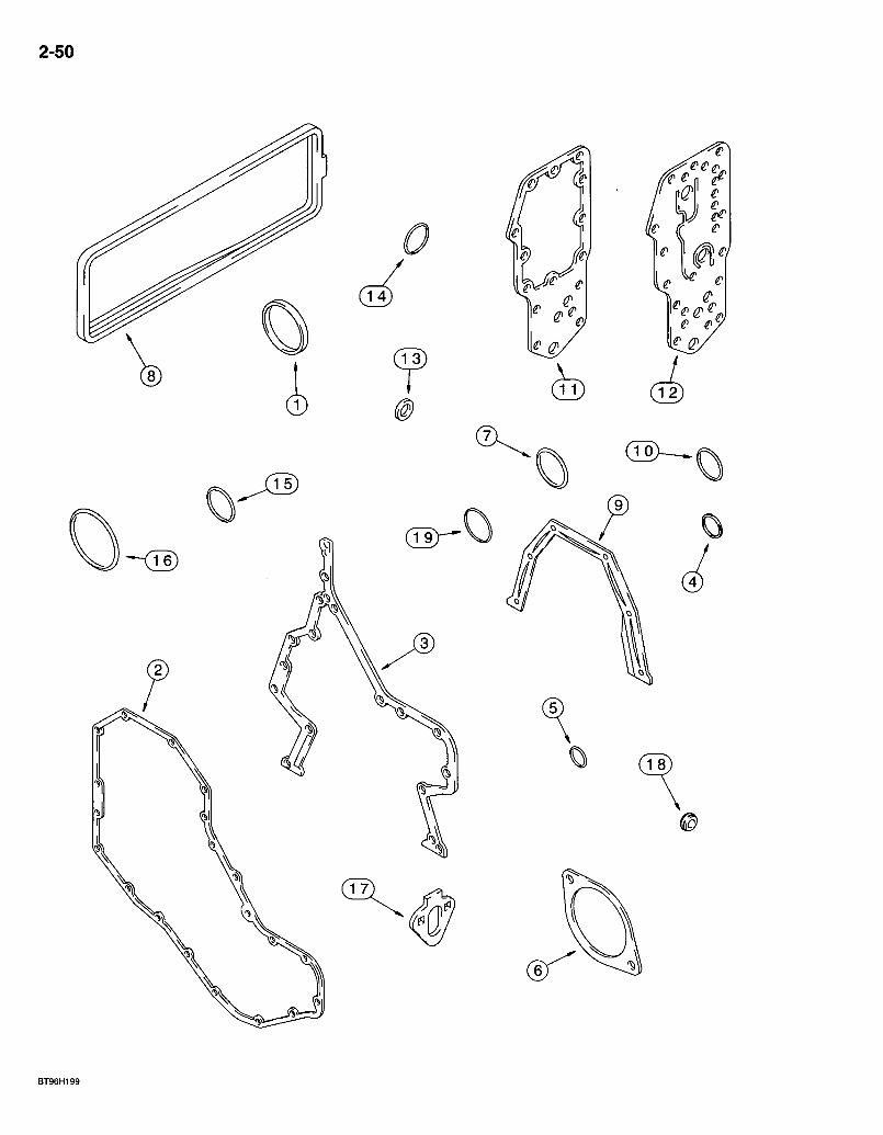
580 Super L Series 2 Loader Backhoe GASKET KIT
4T-390 EMISSIONS CERTIFIED ENGINE
DESCRIPTION
CYLINDER BLOCK
2-51
REQ'D.
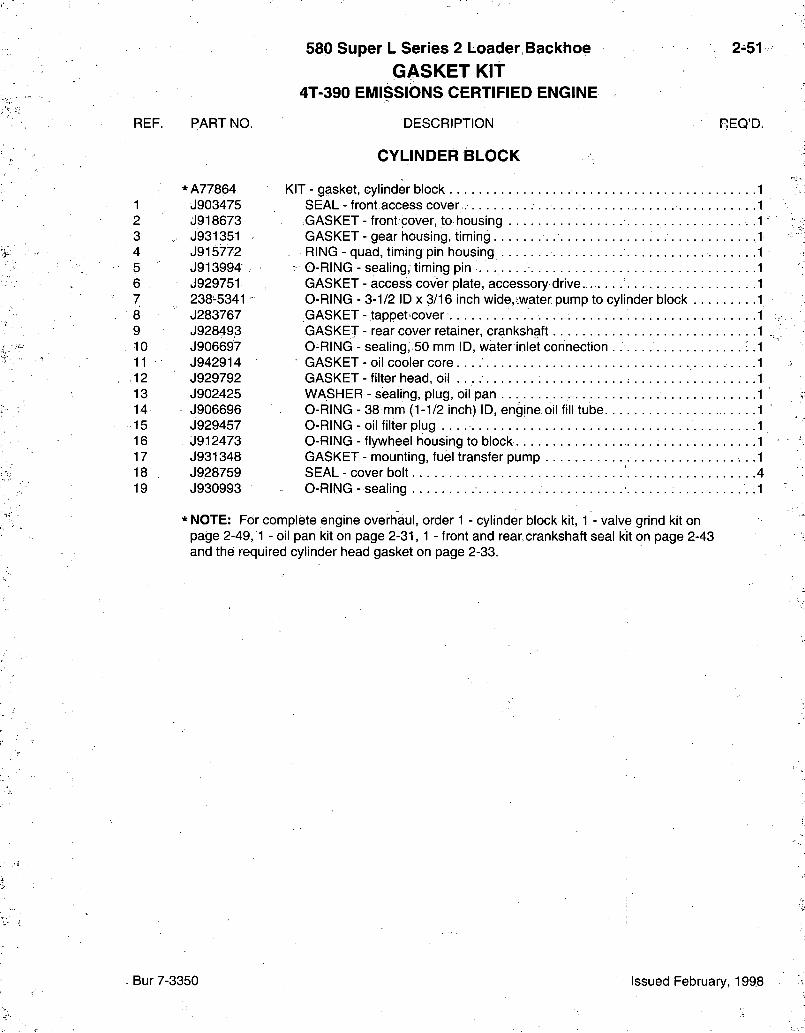
*A77864 1 J903475 2 d918673 3 . J931351 4 J915772 5 • J913994 6 J929751 7. 238-5341 8 J283767 9 J928493 10 J906697 11 J942914 12 J929792 13 J902425 14 J906696 15 J929457 16 J912473 17 J931348 18 J928759 19 J930993
KIT - gasket, cylinder block SEAL - front access cover .. GASKET - front cover, to housing GASKET - gear housing, timing . RING - quad, timing pin housing
- 0-RING - sealing, timing pin . . . . . . access cover plate, accessory drive
3-1/2 ID X 3/16 inch wide, .water pump to cylinder block tappet cover rear cover retainer, crankshaft
sealing, 50 mm ID, water inlet connection ..:. oil cooler c o r e . . . . filter head, oil sealing, plug, oil pan
GASKET 0-RING GASKET GASKET O-RING GASKET GASKET WASHER 0-RING - 38 mm (1-1/2 inch) ID, engine oil fill tube O-RING-oi l filter plug 0-RING - flywheel housing to b lock . . . . GASKET - mounting, fuel transfer pump SEAL-cover bolt 4 O-RING - sealing .1
* NOTE: For complete engine overhaul, order 1 - cylinder block kit, 1 - valve grind kit on page 2-49,1 - oil pan kit on page 2-31, 1 - front and rear.crankshaft seal kit on page 2-43 and the required cylinder head gasket on page 2-33.
Bur 7-3350 Issued February, 1998

2-52
580 Super L Series 2 Loader Backhoe 3-1
ALPHABETICAL INDEX FUEL SYSTEM
DESCRIPTION PAGE
Cover - Loader Lift Frame Tubing 3-3 Filter 3-11 Fuel Reservoir 3-3 Fuel Reservoir Lines 3-3,3-5 Injection System 3-13 Nozzle - Injection 3-19 Pump and Drive - Injection 3-17 Sensor - Fuel Level 3-3 Throttle Control Linkage
Foot Controls 3-9 Hand Control :. 3-7
Bur 7-3350 Issued February, 1998
3-2
C23) ^
®
BT97N162
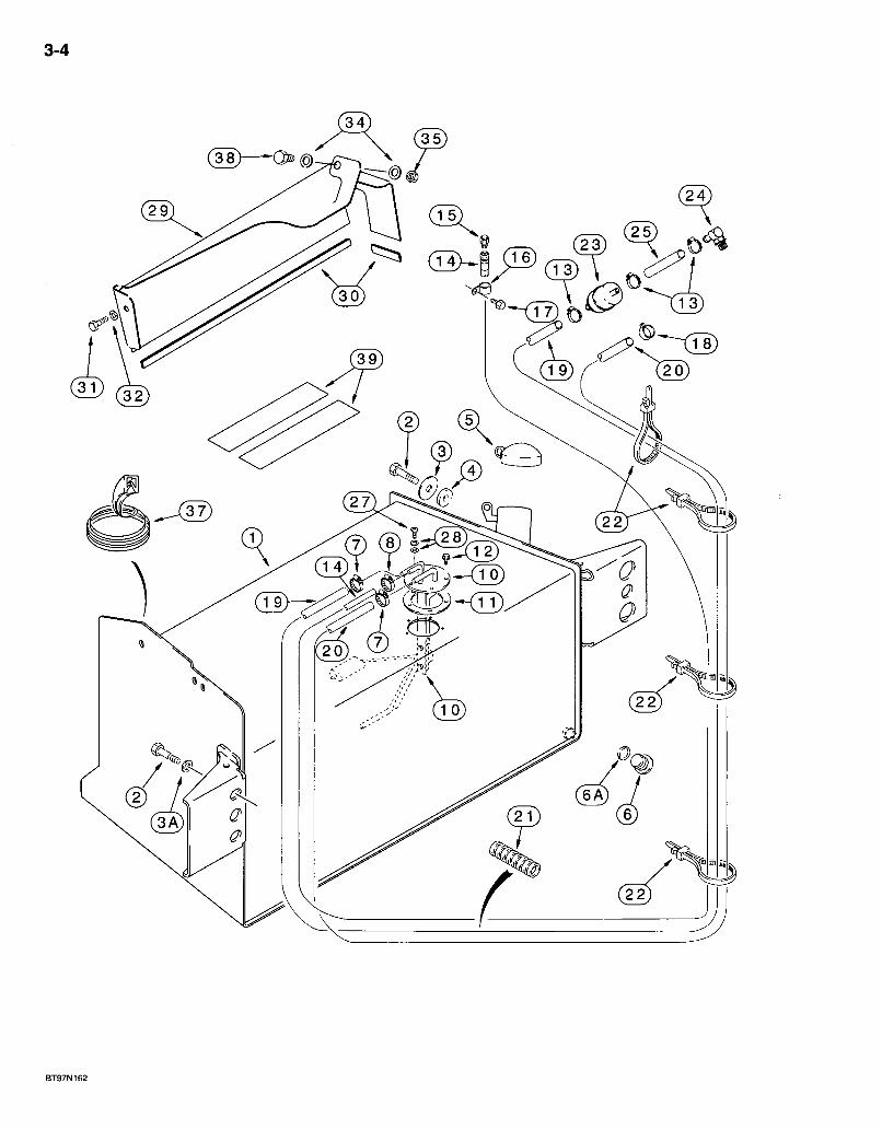
580 Super L Series 2 Loader Backhoe FUEL RESERVOIR AND FUEL LEVEL SENSOR
3-3
REF. 1
1A
2 3 3A 4 5 6
6A •7 8 10 10 11 12 13 "14 15 16 17 18 19 20
21 22 23 24 25
27
28 29
29A
PART NO. 284041A3
281819A4
627-20040 302358At 896-11020
•185926A1 130049A1 218-5211 ,
237-6010 214-1708 214-1704 284431A1 298463A1 188311A2 D75465 196252A1 234892A1 130047A1 515-23127 121856A1 1348264C1 234888A1 284452A2
130048A1 LI 8337 194i99A1 217-372 196247A1
490-11010
D83885 189602A1
188009A1
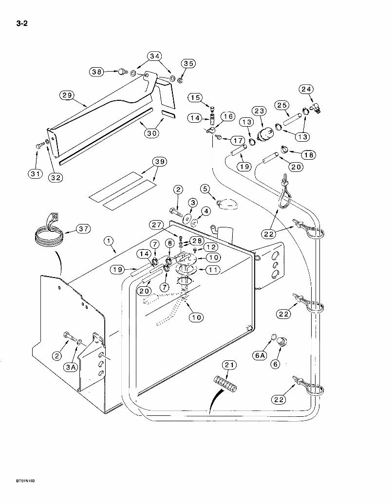
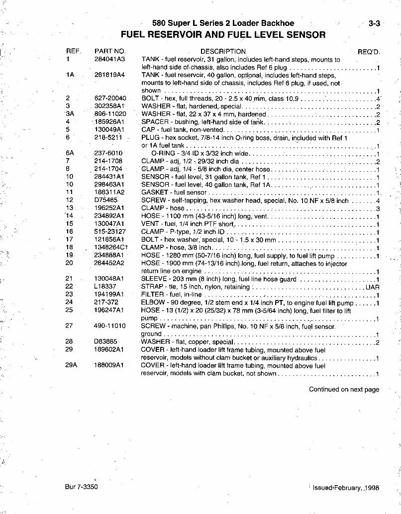
DESCRIPTION REQ'D. TANK - fuel reservoir, 31 gallon, includes left-hand steps, mounts to left-hand side of'Chassis, also includes Ref 6 plug 1 TANK - fuel reservoir, 40 gallon, optional, includes left-hand steps, mounts to left-hand side of chassis, includes Ref 6 plug, if used, not shown 1 BOLT - hex, full threads, 20 - 2.5 x 40 rrim, class 10.9 4 ' WASHER - flat, hardened,,special 2 WASHER - flat, 22 x 37 x 4 mm, harderied 2 SPACER - bushing, left-hand side of tank. 2 CAP - fuel tank, non-vented 1 PLUG - hex socket, 7/8-14 inch Ofring boss, drain, included with Ref 1 or 1A fuel tank
0-RING - 3/4 ID X 3/32 inch wide CLAMP - adj, 1/2 - 29/32 inch dia CLAMP - ad], 1/4 - 5/8 inch dia, center hose SENSOR - fuel level, 31 gallon tank, Ref 1 SENSOR - fuel level, 40 gallon tank, Ref 1A GASKET - fuel sensor SCREW - self-tapping, hex washer head, special. No. 10 NF x 5/8 inch CLAMP-hose HOSE -1100 mm (43-5/16 inch) long, vent VENT - fuel, 1/4 inch PTF short, CLAMP - P-type, 1/2 inch ID BOLT - hex washer, special, 10 -1 .5 x 30 mm CLAMP - hose, 3/8 inch HOSE - 1280 mm-(50-7/16 inch) long,.fuel supply, to fuel lift pump HOSE - 1900 mm (74-13/16 inch)-long, fuel return, attaches to injector return line on engine i
. SLEEVE - 203 mm (8 inch) long, fuel line hose guard STRAP - tie, 15 inch, nylon, retaining UAR FILTER-fuel , in-line ELBOW - 90 degree, 1/2 stem end x 1/4 inch PT, to engine fuel lift pump HOSE - 13 (1/2) X 20 (25/32) x 78 mm (3-5/64 inch) long, fuel filter to lift pump pump SCREW - machine, pan Phillips, No. 10 NF x 5/8 inch, fuel sensor nrr»iinH ground WASHER - flat, copper, special COVER - left-hand loader lift frame tubing, mounted above fuel reservoir, models without clam bucket or auxiliary hydraul ics. . . COVER - left-hand loader lift frame tubing, mounted above fuel reservoir, models with clam bucket, not shown
Continued on next page
Bur 7-3350 lssued:February, J 998
3-4
@
- ^ (13) ^
BT97N162
580 Super L Series 2 Loader Backhoe FUEL RESERVOIR AND FUEL LEVEL SENSOR
3-5
REF. PARTNO. DESCRIPTION REQ'D. 30 * 191046A1 TRIM - edge, 650 mm (25-19/32 inch) long, cut from A165860 bulk trim : 1 31 614-8016 BOLT-hex , full threads, 8 - 1 . 2 5 x 1 6 mm 1 32 895-15008 WASHER - flat, 9 x 20 x 1.6 mm 1 34 895-11010 WASHER - flat, 11 X 20 x 2 mm 1-2 35 829-1410 NUT-hex , 10 mm -1 .5 , class 10.9, 189602A1 cover 1 37 D40442 TRIM - edge, 305 mm (12 inch) long, cut from F42827 bulk trim 1 38 814-10045 BOLT - hex, 10 - 1.5 x 45 mm 1 39 307348A1 PAD - antj-skid, 700 mm (27-9/16 inch) long.. . . . . 2
A165860 TRIM - edge, bulk, 696 mm (27-3/8 inch) long 1
F42827 TRIM - edge, bulk, 2946 mm (116 inch) long UAR
* NOTE: Apply 75 mm (3 inch) of trim to front lower edge and 570 mm (22-7/16 inch) of trim to outside lower edge of cover.
Bur 7-3350 Issued February, 1998
3-6
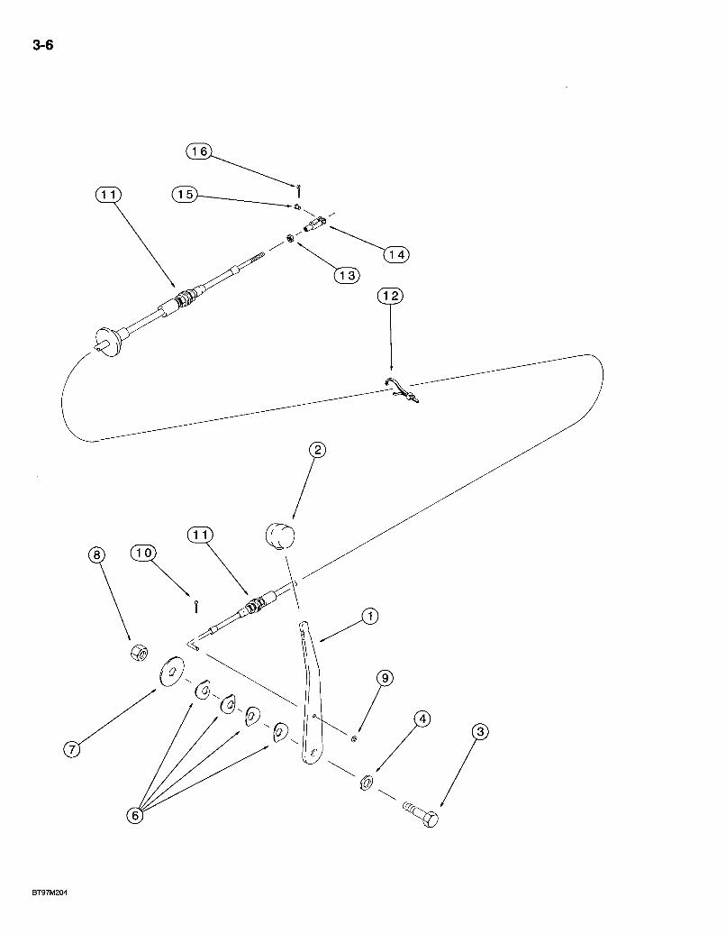
580 Super L Series 2 Loader Backhoe THROTTLE CONTROL LINKAGE
HAND CONTROL
3-7
REF. PART NO. 1 305067A1 2 A177435 3 814-12045 4 896-11012 6 D148962 7 496-81018 8 832-10412 9 495-31022 10 432-48 11 121335A1 12 LI 8337 13 225-14210 14 213-123 15 427-3058 16 432-48
DESCRIPTION LEVER - hand throttle KNOB - lever, lever BOLT - hex, 12 - 1.75 x 45 mm WASHER - flat, 13.5 x 24 x 3 mm, hardened . . WASHER - Belleville WASHER - flat, 33/64 x 2 x 1/8 inch, hardened. NUT - hex, self-locking, 12 mm -1.75 WASHER - flat, 7/32 x 1/2 x 3/64 inch PIN-cotter, 1/16x1/2 inch CABLE - control, hand throttle STRAP - tie, 15 inch, nylon, retaining NUT - hex, No. 10 NF CLEVIS - adjustable, No. 10 NF PIN - clevis, 3/16 x 9/16 inch, hardened PIN-cotter, 1/16x1/2 inch
REO'D.
Bur 7-3350 Issued February, 1998

3-8
@ .1""'
BT97M155

580 Super L Series 2 Loader Backhoe THROTTLE CONTROL LINKAGE
FOOT CONTROLS
3-9
REF. PART NO. 1 282242A1 2 132931A1 2A 189109A1 3 282931A1 4 255291A1 5 256776A1 6 895-11005 7 800-435 8 D124857 9 814-8050 10 892-11008 11 895-11008 12 123558A1 13 123392A1 14 245287A1 15 302846A1 16 838-3640 17 213-123 18 427-3058 19 432-48 20 225-14210 21 275454A1 22 275456A1 23 614-8025 24 892-11008 25 275455A1 26 627-12030 27 892-11012 28 278183A1 29 275457A1 30 492-11025 31 425-154 32 614-6016 33 892-11006 34 895-11006
DESCRIPTION REQ'D. PEDAL - accelerator, plastic BOOT -1/2 inch rod, accelerator pedal rod RETAINER - boot spring ROD - accelerator pedal shaft PIN - throttle pedal SPRING - 1/16 X 1/2 inch WASHER - flat, 5.5 x 10 x 1 mm 2 RING - E-type, external retaining, No. 5 2 BLOCK - cross shaft 4 BOLT - hex, 8 - 1.25 x 50 mm 4 WASHER - lock, 8 mm 4 WASHER - flat, 9 x 17 x 1.6 mm 4 SPRING - throttle return 1 SPACER - spring retaining 1 BRACKET - spring return 1 LEVER - throttle control 1 PIN - roll, 6 X 40 mm 1 CLEVIS - adjustable. No. 10 NF 1 PIN - clevis, 3/16 X 9/16 inch, hardened 1 PIN-cotter, 1/16x1/2 inch 1 NUT-hex, No. 10NF 1 CABLE - throttle, to injection pump 1 BRACKET - throttle, mounts on firewall weld nuts 1 BOLT - hex, full threads, 8 - 1.25 x 25 mm 2 WASHER - lock, 8 mm 2 BRACKET - throttle 1 BOLT - hex, full threads, 12 -1.75 x 30 mm, class 10.9 2 WASHER - lock, 12 mm 2 JOINT-ball 1 BAR - throttle lever 1 WASHER-lock, 1/4 inch 1 NUT-hex, jam, 1/4 inch NF 1 BOLT - hex, full threads, 6 -1.0 x 16 mm 2 WASHER - lock, 6 mm 2 WASHER - flat, 6.6x12 X 1.6 mm 2
Bur 7-3350 Issued February, 1998
3-10
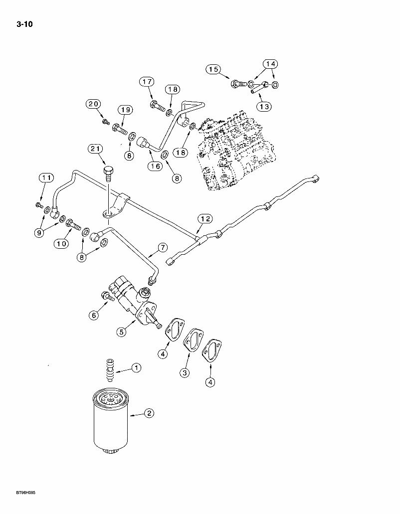
580 Super L Series 2 Loader Backhoe FUEL FILTER AND TRANSFER PUMP
4T-390 EMISSIONS CERTIFIED ENGINE
3-11
REF. PART NO. 1 J925955 2 J931062 3 J914284 4 J931348 5 J933254 6 845-8025 7 J917280 8 J918191 9 J918188'-10 J916361 11 J924726 12 J927633 13 J933250; 14 J918192 15 J932096 16 ) J932035 17 J924725 18 J918192
.- . • J90586d 19 . J911446' 20 'J905403 21 844-8025
DESCRIPTION REQ'D. ADAPTER-fuelfilter. . : 1 FILTER-fuel 1 SPACER - fuel transfer pump mounting 1 GASKET - mountirig, fuel transfer pump 1 PUMP - fuel transfer 1 BOLT - heavy hex flange, 8 - 1.25 x 25 mm .2 TUBE-supply 1 WASHER - sealing, special, 1 2 x 1 8 x 1 mm. .4 WASHER-sealing .2 BOLt - banjo connector, 12 - 1.5 x 24 mm 1 VALVE-check 1 TUBE - manifold, fuel 1 BOLT - banjo connector. 1 WASHER - sealing, special, 14 x 20 x 1 mm 2 VALVE - overflow • .1 TUBE - supply, fuel ^. .1 BOLT - banjo-Connector 1 WASHER-sealing,special, 1 4 x 2 0 x 1 mm .2 BOLT ASSEMBLY - banjo hex, special .1
BOLT - banjo connector, 12 - 1.50 x 24 mm . 1 SCREW - hex, special, vent 1
BOLT - heavy hex flange, 8 - 1.25 x 25 mm 1
Bur 7-3350 Issued February, 1998
3-12
J 6

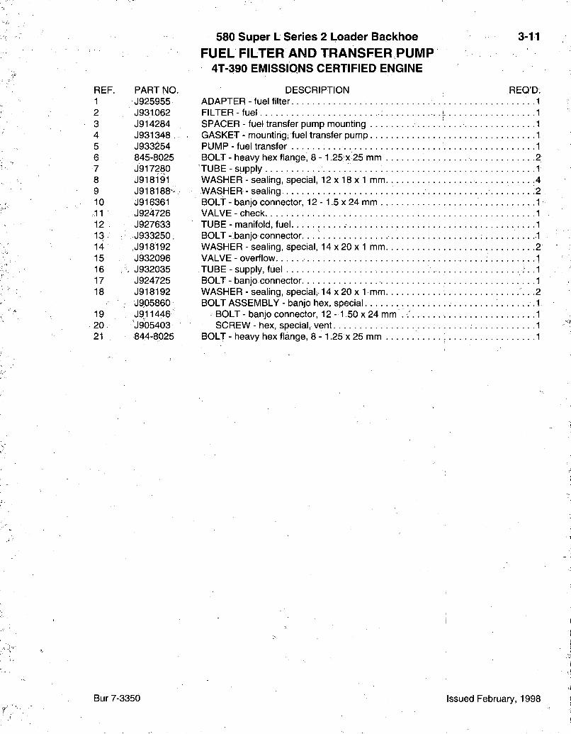
580 Super L Series 2 Loader Backhoe FUEL INJECTION SYSTEM
4T-390 EMISSIONS CERTIFIED ENGINE
3-13
REF. P A R T NO. 1 J930152 2 J929393 3 J929394 4 J929395 5 J929396 6 J927633 7 • J903380 8 J905307 9 J929490 10 J906659 11 J920414 12 J917746 13 J904711 14 J920854 15 J917717 16 J918785 17 J918786 18 J918784
D E S C R I P T I O N R E Q ' D : P U M P A S S E M B L Y - fuel injection, parts list page 3-17 T U B E - fuel injector, No. 1 cylinder T U B E - fuel injector, No. 2 cylinder T U B E - fuel injector. No. 3 cylinder T U B E - fuel injector, No. 4 cylinder T U B E - manifold, fue l . . . . ." S E A L - connector 4 B O L T - banjo drain, special 4 N O Z Z L E A S S E M B L Y - fuel injectibn, parts list page 3-19 4 S E A L - injector nozzle, 7 mm injector tip. . ; 4 B R A C E - f u e l tube C L A M P - f u e l tube 8 B R A C K E T - f u e l tube . . . . : . . . . .4 B O L T - hex, captive washer, special, 5 ^"0.8 x 20 mm 7 B R A C K E T - f u e l tube 2 B R A C E - t u b e . . 1 C L A M P - vibration 2 B R A C E - t u b e 1
Bur7-3350 Issued February, 1998
3-14
0
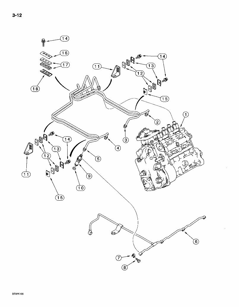
580 Super L Series 2 Loader Backhoe ANEROID AND WASTEGATE SYSTEM
4T-390 ElVIISSIONS CERTIFIED ENGINE
3-15
REF. PART NO. 1 J537560 2 214-1404 3 J926113 4 J920344 5 J920348 6 825-2408 7 221-87 8 J282406 9 217-281 10 222-41 11 J926738 12 J919644 13 J903035 14 J918191
DESCRIPTION REQ'D. ACTUATOR - turbo wastegate, see page 2-27 for mounting of actuator 1 CLAMP - adj, 1/4 - 5/8 inch dia 2 HOSE - 466 mm (18-3/8 inch) long, aneroid to wastegate STUD - valve cover and hose, wastegate actuator mounting CLAMP - hose NUT - hex flange, 8 mm -1.25 REDUCER - pipe, 1/2 male x 1/8 inch female TEE -1/8-27 str thread x fem str thread x fem str thread ELBOW - 45 degree, 1/4 barb end x 1/8 inch PT ELBOW - 90 degree, compression, 3/16 tube OD x 1/8 inch PT TUBE - aneroid, nylon CONNECTOR - banjo BOLT - banjo hex, 12 -1.5 x 24 mm WASHER - sealing, special, 12 x 18 x 1 mm 2
Bur 7-3350 Issued February, 1998
3-16
C) G 0
( 2 7 A )
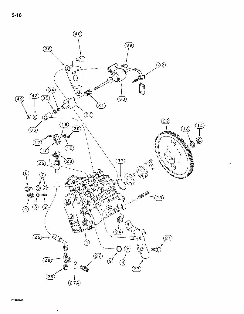
580 Super L Series 2 Loader Backhoe FUEL INJECTION PUMP AND DRIVE
4T-3g0 EMISSIONS CERTIFIED ENGINE
3-17
REF. PART NO. JR930152
JC930153
1 J930152 2 A77720 3 J928981 4 J912888 6 J932096 7 933697R1 8 691292C1 9 680187C1 10 1808728C1 13 A77775 14 A41852 17 1808822C1 18 895-11006 19 892-11006 20 829-1306 21 628-6016 22 J931450 23 J915036 24 825-2410 25 J918536 26 A77512 27 J941472 27A 637-72081 28 J933291 29 218-752 30 J932529 31 NSS 32 NSS 33 NSS 34 NSS 35 NSS 36 NSS 37 J930993 38 J930590 39 845-6012 40 J929456
J802998 41 NSS 42 832-41306 43 J934022
DESCRIPTION REQ'D. PUMP ASSEMBLY - fuel injection, remanufactured, North America only, component parts shown on this page do not apply to the remanufactured assembly, for service order J930152 pump assembly, item 1 "I RETURN NUMBER - use this part number to return pump core for credit when using a remanufactured assembly PUMP ASSEMBLY - fuel injection
PIN - timing WASHER - lock, timing plug PLUG - timing VALVE - overflow WASHER - valve sealing HOUSING - spring return 0-RING - sealing, special LEVER - throttle control WASHER - lock NUT - hex, self-locking BOLT - throttle lever WASHER - flat, 6.6 x 12 x 1.6 mm WASHER - lock, 6 mm NUT - hex, 6 mm -1.0, class 10 BOLT - hex, full threads, 6 -1.0 x 16 mm, class 10.9
GEAR - fuel pump STUD - pump mounting 4 NUT - hex flange, 10 mm -1.5 4 HOSE - flexible ELBOW - 90 degree NIPPLE - hex, 7/16-20 inch flare x 10 -1.0 mm str thread
O-RING - 8.1 ID X 1.6 mm wide TEE - 7/16-20 flare x flare x fem swivel CAP-hex, 7/16-20 inch SOLENOID - fuel shutoff, 12 volt
SPRING - return, plunger STRAP - tie, boot to solenoid BOOT - protective, plunger NUT - hex, jam WASHER - lock JOINT - ball
O-RING - sealing BRACKET - solenoid mounting BOLT - heavy hex flange, 6 -1.0 x 12 mm BOLT-hex, 16-2.0x12 mm KIT - pump shutoff lever
LEVER - pump shutoff NUT - hex, self-locking, 6 mm -1.0, class 10 WASHER - flat, special
Bur 7-3350 Issued February, 1998
3-18
© — ®
B920892S
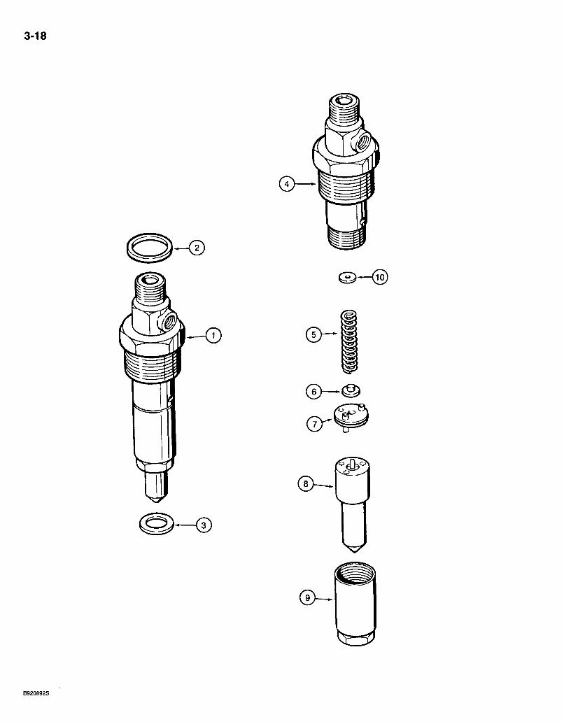
580 Super L Series 2 Loader Backhoe FUEL INJECTION NOZZLE
4T-390 EMISSIONS CERTIFIED ENGINE
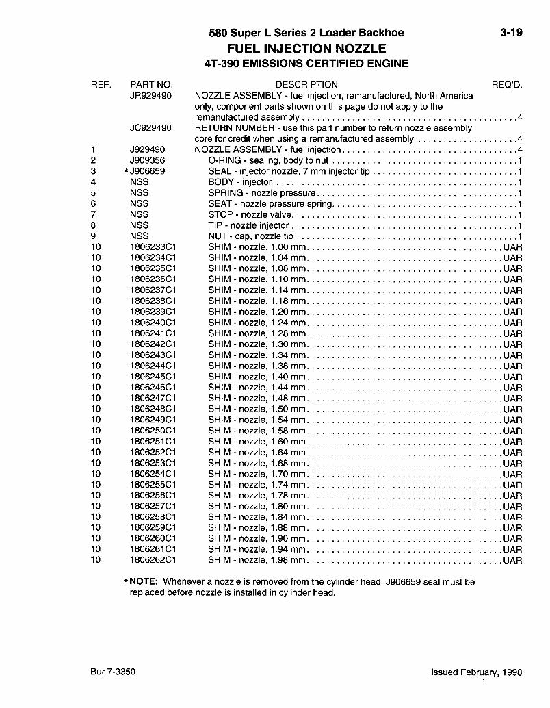
REF.
1 2 3 4 5 6 7 8 9 10 10 10 10 10 10 10 10 10 10 10 10 10 10 10 10 10 10 10 10 10 10 10 10 10 10 10 10 10 10
PART NO. JR929490
JC929490
J929490 J909356
*J906659 NSS NSS NSS NSS NSS NSS 1806233C1 1806234C1 1806235C1 1806236C1 1806237C1 1806238C1 1806239C1 1806240C1 1806241 CI 1806242C1 1806243C1 1806244C1 1806245C1 1806246C1 1806247C1 1806248C1 1806249C1 1806250C1 1806251C1 1806252C1 1806253C1 1806254C1 1806255C1 1806256C1 1806257C1 1806258C1 1806259C1 1806260C1 1806261 CI 1806262C1
3-19
REQ'D. DESCRIPTION NOZZLE ASSEMBLY - fuel injection, remanufactured. North America only, component parts shown on this page do not apply to the remanufactured assembly 4 RETURN NUMBER - use this part number to return nozzle assembly core for credit when using a remanufactured assembly 4 NOZZLE ASSEMBLY - fuel injection 4
0-RING - sealing, body to nut SEAL - injector nozzle, 7 mm injector tip BODY - injector SPRING - nozzle pressure SEAT - nozzle pressure spring STOP - nozzle valve TIP - nozzle injector NUT - cap, nozzle tip SHIM SHIM SHIM SHIM SHIM SHIM SHIM SHIM SHIM SHIM SHIM SHIM SHIM SHIM SHIM SHIM SHIM SHIM SHIM SHIM SHIM SHIM SHIM SHIM SHIM SHIM SHIM SHIM SHIM SHIM
nozzle, nozzle, nozzle, nozzle, nozzle, nozzle, nozzle, nozzle, nozzle, nozzle, nozzle, nozzle, nozzle, nozzle, nozzle, nozzle, nozzle, nozzle, nozzle, nozzle, nozzle, nozzle, nozzle, nozzle, nozzle, nozzle, nozzle, nozzle, nozzle, nozzle.
1.00 mm UAR 1.04 mm UAR 1.08 mm UAR 1.10mm UAR 1.14mm UAR 1.18mm UAR 1.20 mm UAR 1.24 mm UAR 1.28 mm UAR 1.30 mm UAR 1.34 mm UAR 1.38 mm UAR 1.40 mm UAR 1.44 mm UAR 1.48 mm UAR 1.50 mm UAR 1.54 mm UAR 1.58 mm UAR 1.60 mm UAR 1.64 mm UAR 1.68 mm UAR 1.70 mm UAR 1.74 mm UAR 1.78 mm UAR 1.80 mm UAR 1.84 mm UAR 1.88 mm UAR 1.90 mm UAR 1.94 mm UAR 1.98 mm UAR
* NOTE: Whenever a nozzle is removed from the cylinder head, J906659 seal must be replaced before nozzle is installed in cylinder head.
Bur 7-3350 Issued February, 1998

3-20
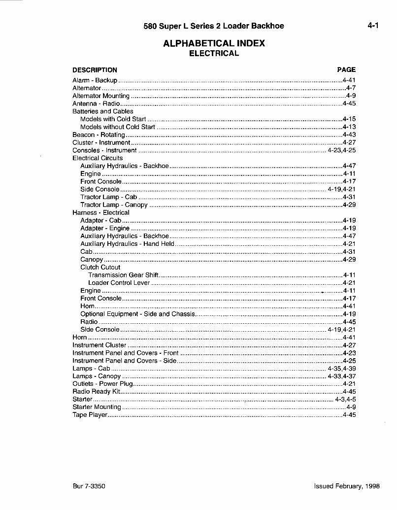
580 Super L Series 2 Loader Backhoe 4-1
ALPHABETICAL INDEX ELECTRICAL
DESCRIPTION PAGE Alarm - Backup 4-41 Alternator 4-7 Alternator Mounting 4-9 Antenna - Radio 4-45 Batteries and Cables
Models with Cold Start 4-15 Models without Cold Start 4-13
Beacon - Rotating 4-43 Cluster - Instrument 4-27 Consoles - Instrument 4-23,4-25 Electrical Circuits
Auxiliary Hydraulics - Backhoe 4-47 Engine 4-11 Front Console 4-17 Side Console 4-19,4-21 Tractor Lamp - Cab 4-31 Tractor Lamp - Canopy 4-29
Harness - Electrical Adapter-Cab 4-19 Adapter - Engine 4-19 Auxiliary Hydraulics - Backhoe 4-47 Auxiliary Hydraulics - Hand Held 4-21 Cab 4-31 Canopy 4-29 Clutch Cutout
Transmission Gear Shift 4-11 Loader Control Lever 4-21
Engine - 4-11 Front Console 4-17 Horn 4-41 Optional Equipment - Side and Chassis 4-19 Radio 4-45 Side Console 4-19,4-21
Horn 4-41 Instrument Cluster 4-27 Instrument Panel and Covers - Front 4-23 Instrument Panel and Covers - Side 4-25 Lamps - Cab 4-35,4-39 Lamps - Canopy 4-33,4-37 Outlets - Power Plug 4-21 Radio Ready Kit 4-45 Starter 4-3,4-5 Starter Mounting 4-9 Tape Player 4-45
Bur 7-3350 Issued February, 1998
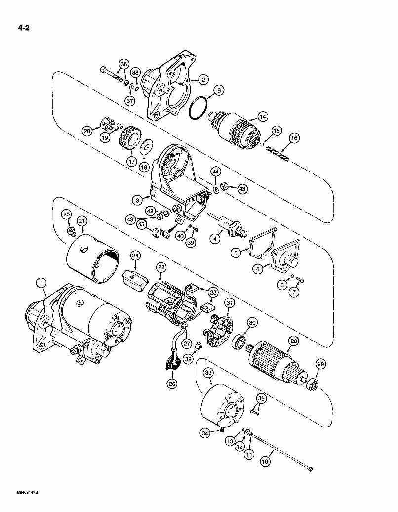
4-2
0
B9408147S
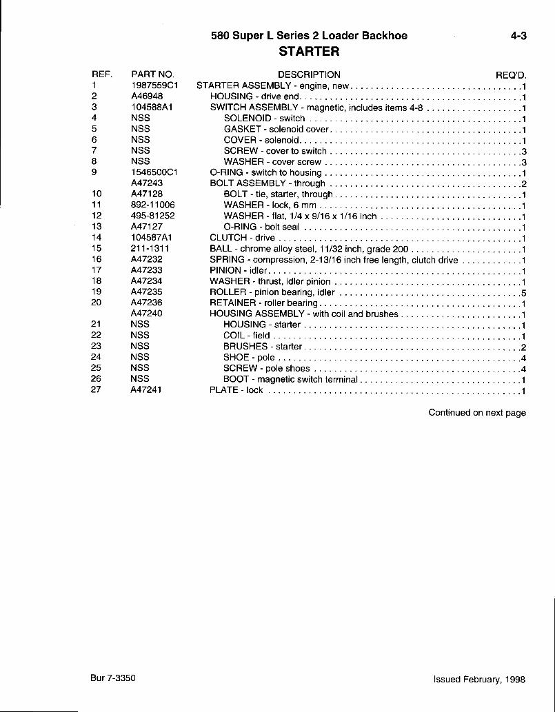
580 Super L Series 2 Loader Backhoe STARTER
4-3
REF. PART NO. 1 1987559C1 2 A46948 3 104588A1 4 NSS 5 NSS 6 NSS 7 NSS 8 NSS 9 1546500C1
A47243 10 A47128 11 892-11006 12 495-81252 13 A47127 14 104587A1 15 211-1311 16 A47232 17 A47233 18 A47234 19 A47235 20 A47236
A47240 21 NSS 22 NSS 23 NSS 24 NSS 25 NSS 26 NSS 27 A47241
DESCRIPTION REQ'D. STARTER ASSEMBLY - engine, new
HOUSING - drive end SWITCH ASSEMBLY - magnetic, includes items 4-8
SOLENOID - switch GASKET - solenoid cover COVER - solenoid SCREW - cover to switch WASHER - cover screw
0-RING - switch to housing BOLT ASSEMBLY - through
BOLT - tie, starter, through WASHER - lock, 6 mm WASHER - fiat, 1/4x9/16x1/16 inch 0-RING - bolt seal
CLUTCH - drive BALL - chrome alloy steel, 11/32 inch, grade 200 SPRING - compression, 2-13/16 inch free length, clutch drive PINION-idler WASHER - thrust, idler pinion ROLLER - pinion bearing, idler RETAINER - roller bearing HOUSING ASSEMBLY - with coil and brushes
HOUSING - starter COIL - field BRUSHES - starter 2 SHOE - pole 4 SCREW - pole shoes 4 BOOT - magnetic switch terminal 1
PLATE-lock 1
Continued on next page
Bur 7-3350 Issued February, 1998
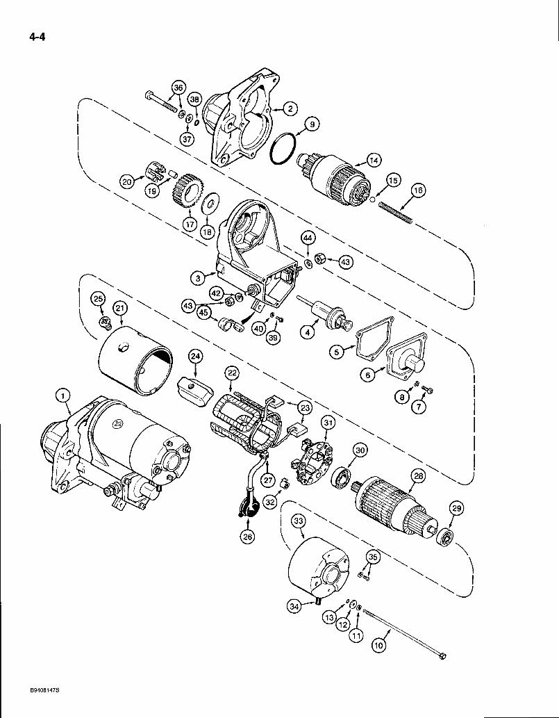
4-4
0
-J
®
B9408147S

580 Super L Series 2 Loader Backhoe STARTER
4-5
REF. PART NO. REF
28 A47242 29 452698C1 30 A47247 31 A47239 32 A47249 33 A47237 34 A47238 35 A47244
A47230 36 A47129 37 195-2015 38 A47130 39 A46950 40 892-11005 42 892-11010 43 825-1410 44 A10454 45 104589A1
DESCRIPTION STARTER ASSEMBLY - engine (continued from previous page).
ARIVIATURE ASSEMBLY - starter BEARING - ball BEARING - drive end
HOLDER ASSEMBLY - brush (Includes 2 brushes)
REQ'D.
SPRING - brush tension 4 FRAME - commutator end 1 COVER - end frame 1 SCREW ASSEMBLY - with washer, brush retaining, brush holder to cover 2 BOLT ASSEMBLY - commutator end cover to drive end housing 3
BOLT ASSEMBLY - with washer WASHER - fiat, 1/4 x 1-3/4 x 1/16 inch O-RING - bolt seal
SCREW - terminal, special, 5 x 8 mm WASHER - lock, 5 mm WASHER-lock, 10 mm NUT - hex, 10 mm -1.5, field coil terminal WASHER - spring, field coil terminal BUSHING - insulation
Bur 7-3350 Issued February, 1998
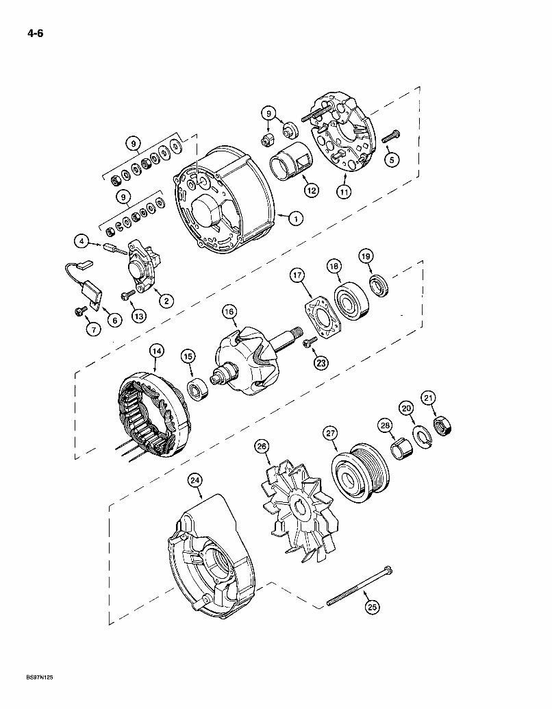
4-6
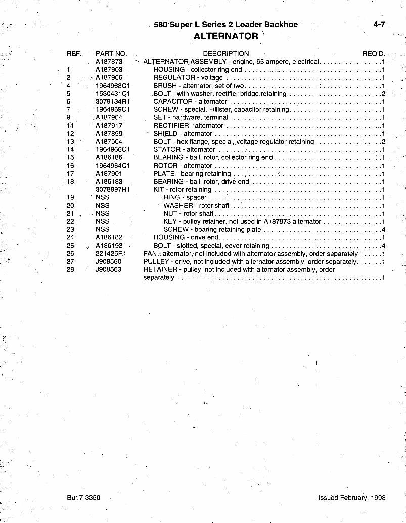
580 Super L Series 2 Loader Backhoe ALTERNATOR
4-7
REF. PART NO. A187873
1 A187903 2 :A187906 4 1964968C1 5 1530431 CI 6 3079134R1 7 1964969C1 9 A187904
Ai87917 12 A187899 13 A187504 14 1964966C1 15 A186186 16 1964964C1 17 A187901 18 A186183
3078897R1 19 NSS 20 NSS 21 NSS 22 NSS 23 NSS 24 A186182 25 . A186193 26 221425R1 27 J908560 28 J908563
DESCRIPTION REQ'D. ALTERNATOR ASSEMBLY - engine, 65 ampere, electrical .
HOUSING - collector ring end REGULATOR - voltage BRUSH - alternator, set of two BOLT - with washer, rectifier bridge retaining CAPACITOR - alternator SCREW - special, Fillister, capacitor retaining SET- hardware, terminal RECTIFIER- alternator SHIELD - alternator BOLT - hex flange, special, voltage regulator retaining STATOR - alternator BEARING - ball, rotor, collector ring end ROTOR - alternator PLATE - bearing retaining BEARING - ball, rotor, drive end KIT - rotor retaining
RING - spacer: ; WASHER - rotor shaft. .
NUT - rotor shaft KEY - pulley retainer, not used in A187873 alternator SCREW - bearing retaining plate
HOUSING - drive end. . . . . BOLT - slotted, special, cover retaining 4
FAN - alternator,"not included with alternator assembly, order separately . . . . . PULLEY - drive, not included with alternator assembly, order separately RETAINER - pulley, not included with alternator assembly, order separately 1
Bur 7-3350 Issued February, 1998
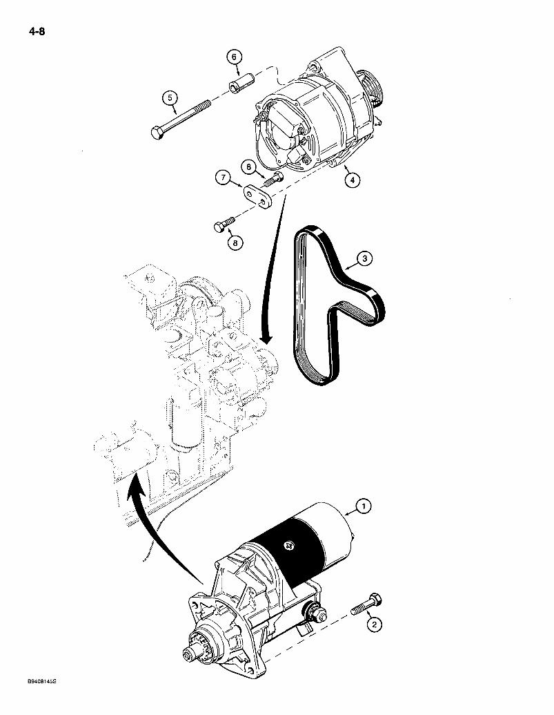
4-8
B9408145S
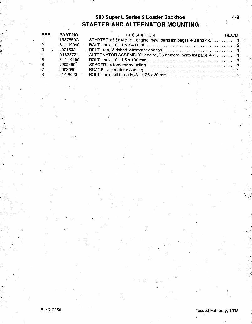
580 Super L Series 2 Loader Backhoe STARTER AND ALTERNATOR MOUNTING
4-9
REF. PART NO. 1 1987559C1 2 814-10040 3 J921603 4 A187873 5 814-10100 6 J902469 7 J903089 8 : 614-8020
DESCRIPTION REQ'D. STARTER ASSEMBLY - engine, new, parts list pages 4-3 and 4-5 1 BOLT - hex, 10 - 1.5 x 40 mm 2 BELT - fan, V-ribbed, alternator and fan ALTERNATOR ASSEMBLY - engine, 65 ampere, parts list page 4-7 BOLT-hex, 10-1.5x100 mm SPACER - alternator mounting BRACE - alternator mounting BOLT-hex, full threads, 8-1.25 x 20 mm . 2
Bur 7-3350 Issued February, 1998
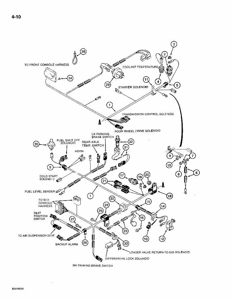
4-10
TO FRONT CONSOLE HARNESS COOLANT TEMPERATURE
STARTER SOLENOID
TRANSMISSION CONTROL SOLENOID
FOUR WHEEL DRIVE SOLENOID LH PARKING BRAKE SWITCH
FUEL SHUT OFF SOLENOID REAR AXLE
TEMP. SWITCH
HORN
GOLD START SOLENOID
TO SIDE CONSOLE HARNESS
POSITION SWITCH
BACKUP ALARM
FUEL LEVEL SENDER
TO AIR SUSPENSION SEAT
-LOADER VALVE RETURN-TO-DIG SOLENOID
DIFFERENTIAL LOCK SOLENOID
RH PARKING BRAKE SWITCH
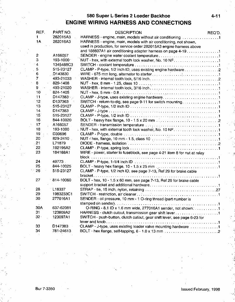
580 Super L Series 2 Loader Backhoe ENGINE WIRING HARNESS AND CONNECTIONS
4-11
REF. PART NO. 1 282015A3 1A 282016A3
2 A166057 3 193-1000 4 1345488C3 5 515-23127 6 D143830 7 493-21033 8 829-1408 9 493-21020 10 824-1405 11 D147383 -12 D137363 13 515-23127 14 D147383 15 515-23127 16 844-10020 17 A166057 18 193-1000 19 • D39696 20 829-2410 21 L71879 22 192196A2 23 184188A1
24 49773 25 844-10025 26 515-23127
27 814-10060
28 LI 8337 29 1983233C1 30 277016A1
30A 637-62081 31 123809A2 32 123097A1
33 D147383 34 781-24613
DESCRIPTION REQ'D. HARNESS - engine, main, models without air conditioning 1 HARNESS - engine, main, models with air conditioning, not shown, used in production, for service order 282015A3 engine harness above and 186607A1 air conditioning adapter harness on page 4-19 SENDER - engine water coolant temperature NUT - hex, with external tooth lock washer, No. 10 NF SWITCH - coolant temperature CLAMP - P-type, 1/2 inch ID, uses existing engine hardware WIRE - 675 mm long, alternator to starter WASHER - internal tooth lock, 5/16 inch NUT - hex, 8 mm -1.25, class 10 WASHER - internal tooth lock, 3/16 inch. NUT - hex, 5 mm - 0.8 CLAMP - J-type, uses existing engine hardware SWITCH - return-to-dig, see page 9-11 for switch mounting CLAMP - P-type, 1/2 inch ID CLAMP - J-type CLAMP - P-type, 1/2 inch ID BOLT - heavy hex flange, 10 -1.5 x 20 mm . SENDER - transmission temperature NUT - hex, with external tooth lock washer. No. 10 NF CLAMP - P-type, double NUT - hex, flange, 10 mni -1.5, class 10: DIODE - harness, isolation CLAMP - P-type, spring lock WIRE - power, starter to fuseblock, see page 4-21 item 8 for nut at relay block CLAMP - P-type, 1-1/4 inch ID BOLT - heavy hex flange, 10 -1.5 x 25 mm CLAMP - P-type, 1/2 inch ID, see page 7-13, Ref 29 for brake.cable bracket BOLT - hex, 10 -1.5 x 60 mm, see page 7-13, Ref 29 for brake cable support bracket and additional hardware. STRAP - tie, 15 inch, nylon, retaining 27 SWITCH - restriction, air cleaner. SENDER - oil pressure, 10 mm -1 O-ring thread (part number is stamped on sender)
O-RING - 8.1 ID X 1.6 mm wide, 277016A1 sender, not shown. HARNESS - clutch cutout, transmission gear shift lever SWITCH - push-button, clutch cutout, gear shift lever, see page 6-23 for lever and knob CLAMP - J-type, uses,existing loader valve mounting hardware BOLT - hex flange, self-tapping, 6 -1.0 x 13 mm 2
Bur 7-3350 Issued February, 1998
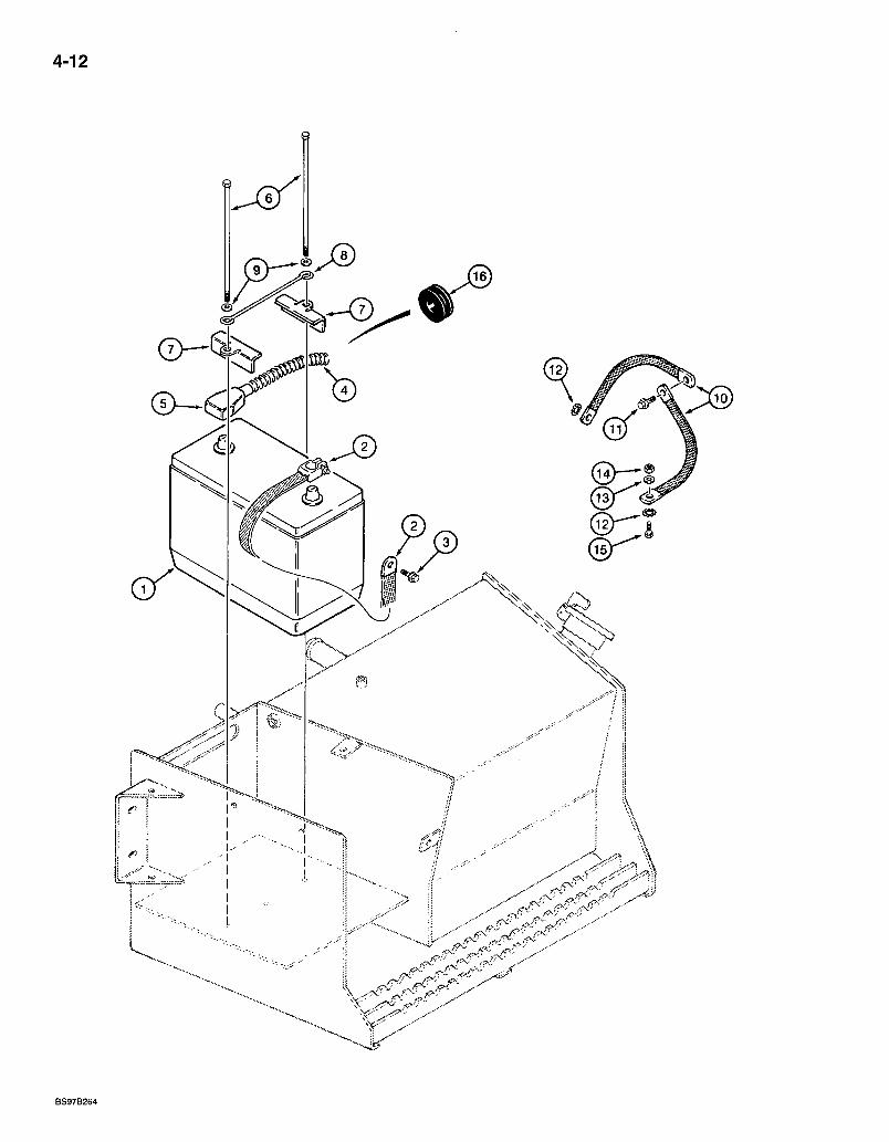
4-12
BS97B264
580 Super L Series 2 Loader Backhoe 4-13 BATTERY AND BATTERY C A B L E S
IVIODELS WITHOUT COLD START
REF. PART NO. DESCRIPTION REQ'D. 1 BMF31E BATTERY - dry, 12 volt, models without cold start 1 2 'D83485 STRAP - battery, negative ground 1 3 844-10020 BOLT - heavy hex flange, 10 -1.5 X 20 mm, negative battery cable
ground bolt to chassis 1 4 144171A1- CABLE-positive, 1500 mm long 1 5 383619R1 BOOT - positive battery cable 1 6 814-10245 BOLT-hex, 10- 1.5x245 mm. 2 7 D125079 BRACKET - battery hold-down . 2 8 D55561 RETAINER - battery .1 9 495-11041 WASHER-flat, 13/32x13/16x1/16 inch 2 10 D127018 STRAP - ground 2 11 844-10025 BOLT-heavy hex flange, 10 -1 .5x25 mm 1 12 493-11039 WASHER - internal-external tooth.lpck, 3/8 inch 2 13 895-15008 WASHER - flat, 9 x 20 x 1.6 mm . . . . 1 14 829-1408 NUT-hex, 8 mm -1.25, class 10 . . 1 15 814-8035 BOLT - hex, 8 - 1.25 x 35 mm 1 16 257279A1 GROMMET - battery cable, mounts in chassis side channel 2
NOTE: See page 9-79 for battery box.
Bur 7-3350 Issued February, 1998
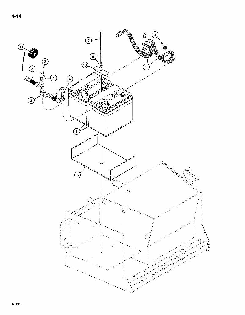
4-14
580 Super L Series 2 Loader Baclthoe DUAL BATTERY COLD START
4-15
REF. PART NO. 1 BMF28S 2 184498A1 3 184497A1 4 D126409 5 •73383 6 181338A1 7 814-10245 8 495-11041 10 250854A1 11 • 257279A1
DESCRIPTION REQ'D. BATTERY - dry charged, 12 volt, models with cold start .2 CABLE - positive, 1460 mm long. . 1 CABLE - positive jumper, 227 mm long,. 1 NUT - hex, special, 3/8 inch NC, battery terminal 4 STRAP - ground, flat 2 PLATE - battery mounting 1 BOLT- hex, 10- 1.5x245 mm 1 WASHER - flat, 13/32 x 13/16 x 1/16 inch • 1 RETAINER - battery plate, top 1 GROMMET - battery cable, mounts in chassis side channel 2
Bur 7-3350 Issued February, 1998
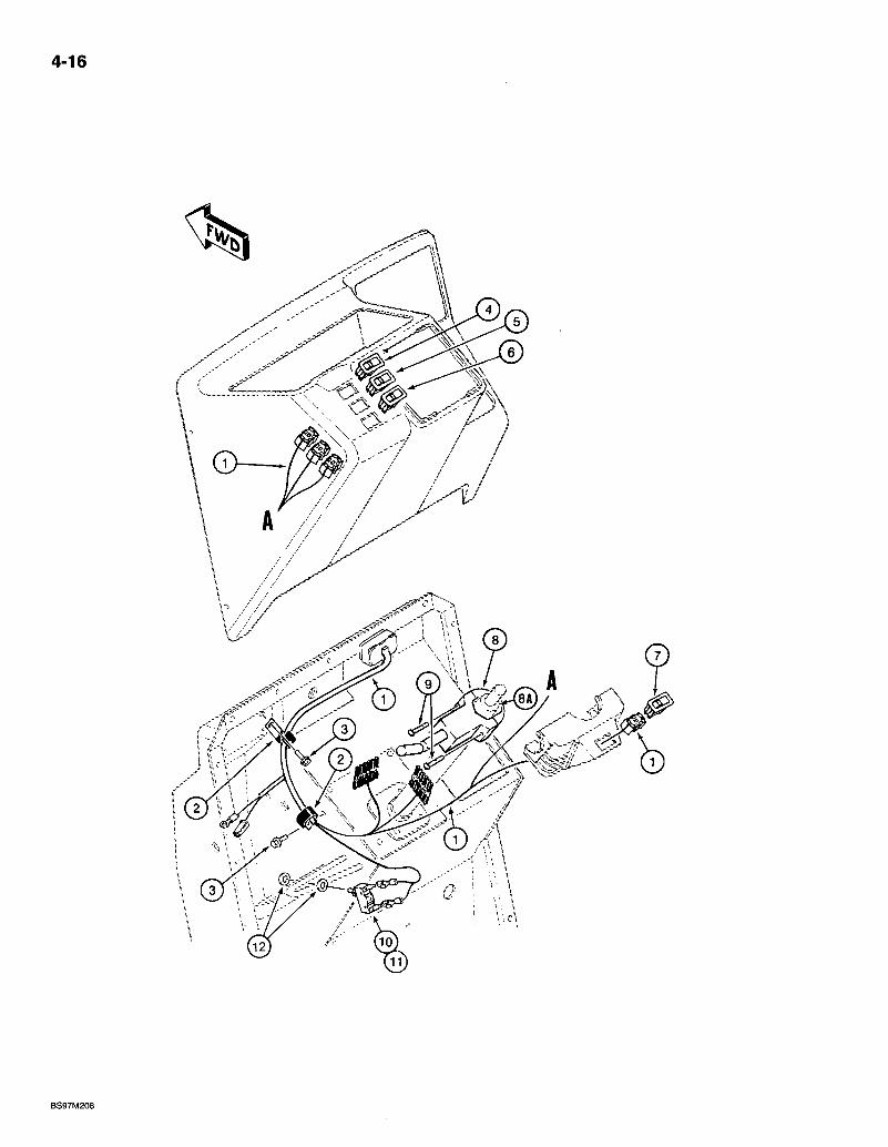
4-16
BS97M208

580 Super L Series 2 Loader Backhoe FRONT CONSOLE WIRING HARNESS AND CONNECTIONS
4-17
REF. PART NO. 1 282014A2 2 D147383 3 781-24820 4 123538A1
5 122736A1 6 13169-1A1 7. 122740A1 8 278328A1
8 231520A2
8A 236521A1 279520A1
9 840-1535 10 • D148108 11 A187990 12 495-81153
DESCRIPTION REO'D. HARNESS - front console 1 CLAMP - J-type, harness to firewall 2 BOLT - hex flange, self-tapping, 8 - 1.25 x 20 mm . . . . 2 SWITCH - rocker, dome lamp, if used, see page 4-23 for plug used in place of switch 1 SWITCH - rocker, hazard, flasher lamps 1 SWITCH - rocker, turn signal 1 SWITCH - rocker, horn ., 1 LEVER - shuttle shift, transmission, forward/neutral/reverse switch, standard transmission .1 LEVER - shuttle.shift, transmission, fonward/neutral/reverse switch, powershift transmission 1 COLLAR - shuttle lever, includes clamp and (2) nuts 1 BOOT - rubber, handle, shuttle shift lever, not shown. . . . 1 SCREW - machine, pan Phillips, 5 - 0.8 x 35 mm 2 SWITCH - rocker, brake lamp 1 TERMINAL - male 2 WASHER - flat, 15/32 x 3/4 x 1/32 inch 2
Bur 7-3350 Issued February, 1998
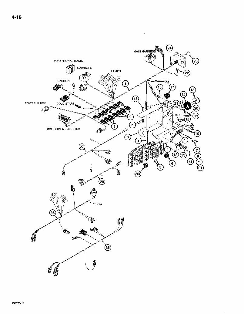
4-18
TO OPTIONAL RADIO
C A B / R O P S
P O W E R P L U G S C O L D START
MAIN H A R N E S S
LAMPS
IGNITION
INSTRUMENT C L U S T E R
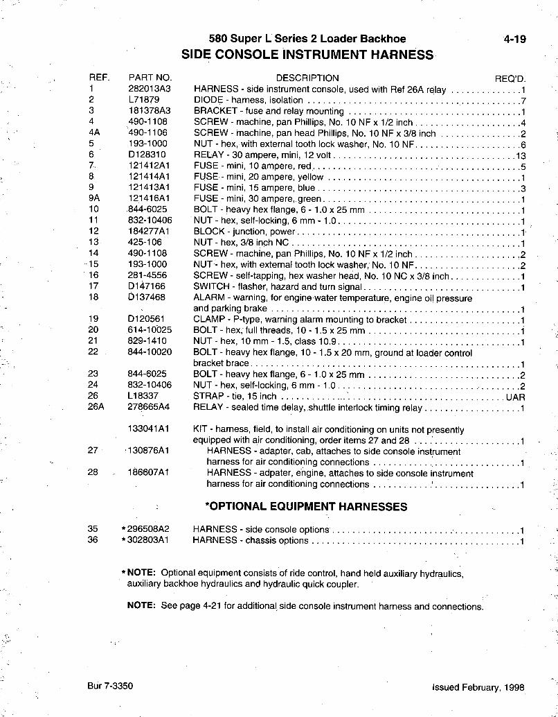
580 Super L Series 2 Loader Backhoe S I D E C O N S O L E I N S T R U M E N T H A R N E S S
4-19
REF. PART NO. 1 282013A3 2 L71879 3 181378A3 4 490-1108 4A 490-1106 5 193-1000 6 D128310 7, 121412A1 8 121414A1 9 121413A1 9A 121416A1 10 844-6025 11 832-10406 12 184277A1 13 425-106 14 490-1108 15 193-1000 16 281-4556 17 D147166 18 D137468
19 D120561 20 614-10025 21 829-1410 22 844-10020
23 844-6025 24 832-10406 26 LI 8337 26A 278665A4
133041A1
27 130876A1
28 186607A1
35 *296508A2 36 *302803A1
DESCRIPTION REQ'D. HARNESS - side instrument console, used with Ref 26A relay 1 DIODE - harness, isolation 7 BRACKET - fuse and relay mounting 1 SCREW - machine, pan Phillips, No. 10 NF x 1/2 inch 4 SCREW - machine, pan head Phillips, No. 10 NF x 3/8 inch 2 NUT - hex, with external tooth lock washer, No. 10 NF 6 RELAY - 30 ampere, mini, 12 volt 13 FUSE - mini, 10 ampere, red 5 FUSE - mini, 20 ampere, yellow 1 FUSE - mini, 15 ampere, blue 3 FUSE - mini, 30 ampere,.green 1 BOLT - heavy hex flange, 6 - 1.0 x 25 mm 1 NUT - hex, self-locking, 6 mm -1 .0 1 BLOCK - junction, power 1 NUT - hex, 3/8 inch NC 1 SCREW - machine, pan Phillips, No. 10 NF x 1/2 inch 2 NUT - hex, with external tooth lock washer, No. 10 NF 2 SCREW - self-tapping, hex washer head, No. 10 NC x 3/8 inch 1 SWITCH - flasher, hazard and turn signal 1 ALARM - warning, for engine water temperature, engine oil pressure and parking brake 1 CLAMP - P-type, warning alarm mounting to bracket 1 BOLT - hex, full threads, 10 -1 .5 x 25 mm 1 NUT - hex, 10 mm -1 .5 , class 10.9 1 BOLT - heavy hex flange, 10 -1 .5 x 20 mm, ground at loader control bracket brace 1 BOLT - heavy hex flange, 6 - 1.0 x 25 mm 2 NUT - hex, self-locking, 6 mm -1.0 2 STRAP- t ie , 15 inch UAR RELAY - sealed time delay, shuttle interlock timing relay 1
KIT - harness, field, to install air conditioning on units not presently equipped with air conditioning, order items 27 and 28 1
HARNESS - adapter, cab, attaches to side console instrument harness for air conditioning connections • .1 HARNESS - adpater, engine, attaches to side console instrument harness for air conditioning connections 1
*OPTIONAL EQUIPMENT HARNESSES
HARNESS - side console options 1 HARNESS - chassis options 1
*NOTE: Optional equipment consists of ride control, hand held auxiliary hydraulics, auxiliary backhoe hydraulics and hydraulic quick coupler.
NOTE: See page 4-21 for additional side console instrument harness and connections.
Bur 7-3350 Issued February, 1998
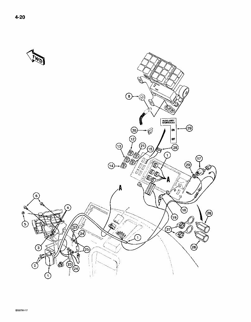
4-20
AUXIUART uroRAUUCS
@
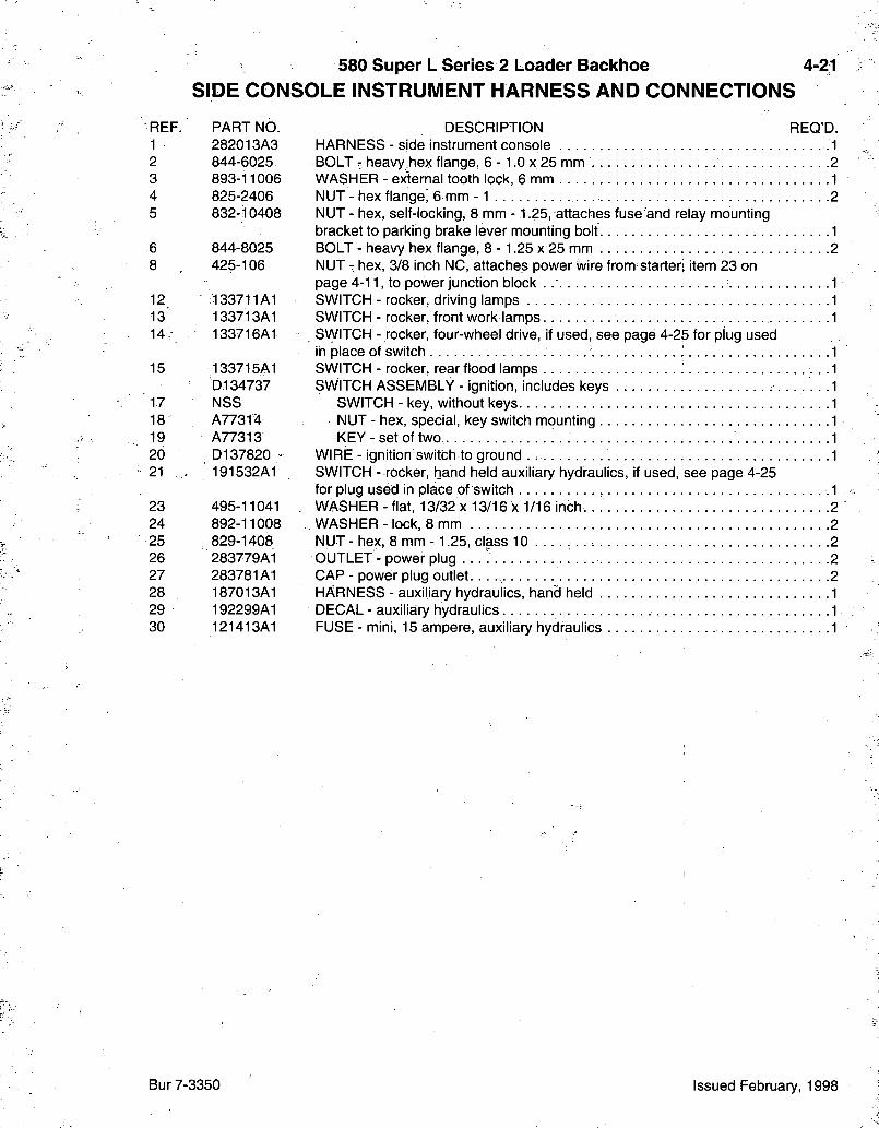
580 Super L Series 2 Loader Backhoe 4-21 S I D E C O N S O L E I N S T R U M E N T H A R N E S S A N D C O N N E C T I O N S
REF. PART NO. 1 282013A3 2 844-6025 3 893-11006 4 825-2406 5 832-10408
6 844-8025 8 425-106
12 133711A1 13' 133713A1 14, 133716A1
15 133715A1 D134737
17 NSS 18 A773f4 19 A77313 20 D137820 " 21 - 191532A1
23 495-11041 24 892-11008 25 829-1408 26 283779A1 27 283781A1 28 187013A1 29 192299A1 30 121413A1
DESCRIPTION REQ'D. HARNESS - side instrument console -1 BOLT - heavy hex flange, 6 -1 .0 x 25 mm 2 WASHER - external tooth lock, 6 mm 1 NUT - hex flange^ 6 mm - 1 2 NUT - hex, self-locking, 8 mm -1.25, attaches fuse and relay mounting bracket to parking brake lever mounting bolt 1 BOLT - heavy hex flange, 8 -1 .25 x 25 mm .2 NUT - hex, 3/8 inch NC, attaches power wire from starter; item 23 on page 4-11, to power junction block . . : 1 SWITCH - rocker, driving lamps 1 SWITCH - rocker, front work lamps 1 SVyiTCH - rocker, four-wheel drive, if used, see page 4-25 for plug used in place of switch 1 SWITCH - rocker, rear flood lamps 1 SWITCH ASSEMBLY - ignition, includes keys 1
SWITCH - key, without keys 1 NUT - hex, special, key switch mounting 1 KEY-se t of two,. 1
WIRE - ignition switch to ground 1 SWITCH - rocker, hand held auxiliary hydraulics, if used, see page 4-25 for plug used in place of switch .1 WASHER - flat, 13/32 x 13/16 x 1/16 inch 2 WASHER- lock, 8 mm 2 NUT - hex, 8 mm -1.25, class 10 . . . . . . . 2 OUTLET - power plug . . . 7 2 CAP - power plug outlet. 2 HARNESS - auxiliary hydraulics, hand held 1 DECAL - auxiliary hydraulics 1 FUSE - mini, 15 ampere, auxiliary hydraulics 1
Bur 7-3350 Issued February, 1998

4-22
Ui i I
R O T A T E D 90 FOR C L A R I T Y
B9501058S

580 Super L Series 2 Loader Backhoe F R O N T I N S T R U M E N T P A N E L A N D C O V E R S
4-23
REF. PART NO. 1 119266A1 1A 181316A1
2 137851A1
3 844-8020 4 555-2
5 - 833-40406 6 119267A2 7 : 119268A1 8 140-107 9 131-623 10 : 177164A1
11 140-107 12 176857A1 13 126844A1 14 136450A1
15 140-107 16 495-31022 17 . 225-14110 18 136454A1 19 •126821 20 151-522 21 495-31022 24 D127335
DESCRIPTION REQ'D. PANEL - instrument, front, cab models, item 1A shown 1 PANEL - instrument, front, POPS canopy models, with four bolt holes for anti-vandalism cover 1 PLATE - bar, front console mounting to firewall, not included in cab frame .2 BOLT - heavy hex flange, 8 -1.25 x 20 mm 10 BOLT - heavy hex flange, 6 -1 .0 x 20 mm, special, instrument panel to firewall 4 NUT-U- type, 6 m m - 1 . 0 4 COVER - upper, steering column 1 COVER - lower, steering co lumn. . 1 SCREW - machine, pan head Phillips, No. 10 NC x 3/4 inch 3 NUT - U-type, No. 10 NC. . . . . , 1 BOX - storage compartment (service with 122641 A l box and 120029A1 cover, not shown) 1 SCREW - machine, pan head Phillips, No. 10 NC x 3/4 inch 4 NUT-J- type, No. 10 ,A PLUG - upper, used in place;of dome lamp switch, if used 1 BRACKET - front instrument panel, anti-vandalism, ROPS canopy models .1 SCREW - machine, pan head Phillips, No. 10 NC x 3/4 inch 4 WASHER - flat, 7/32 X 1/2 x 3/64 inch. 4 NUT - hex. No. 10 NC . . . 4 COVER - anti-vandalism, front instrument panel, ROPS canopy models 1 CORD - manual retaining, anti-vandalism cover 1 RIVET - break mandrel, 3/16x 9/16 inch 2 WASHER - flat, 7/32 x 1/2 x 3/64 inch 4 RETAINER - magnetic catch, storage compartment 1
Bur 7-3350 Issued February, 1998
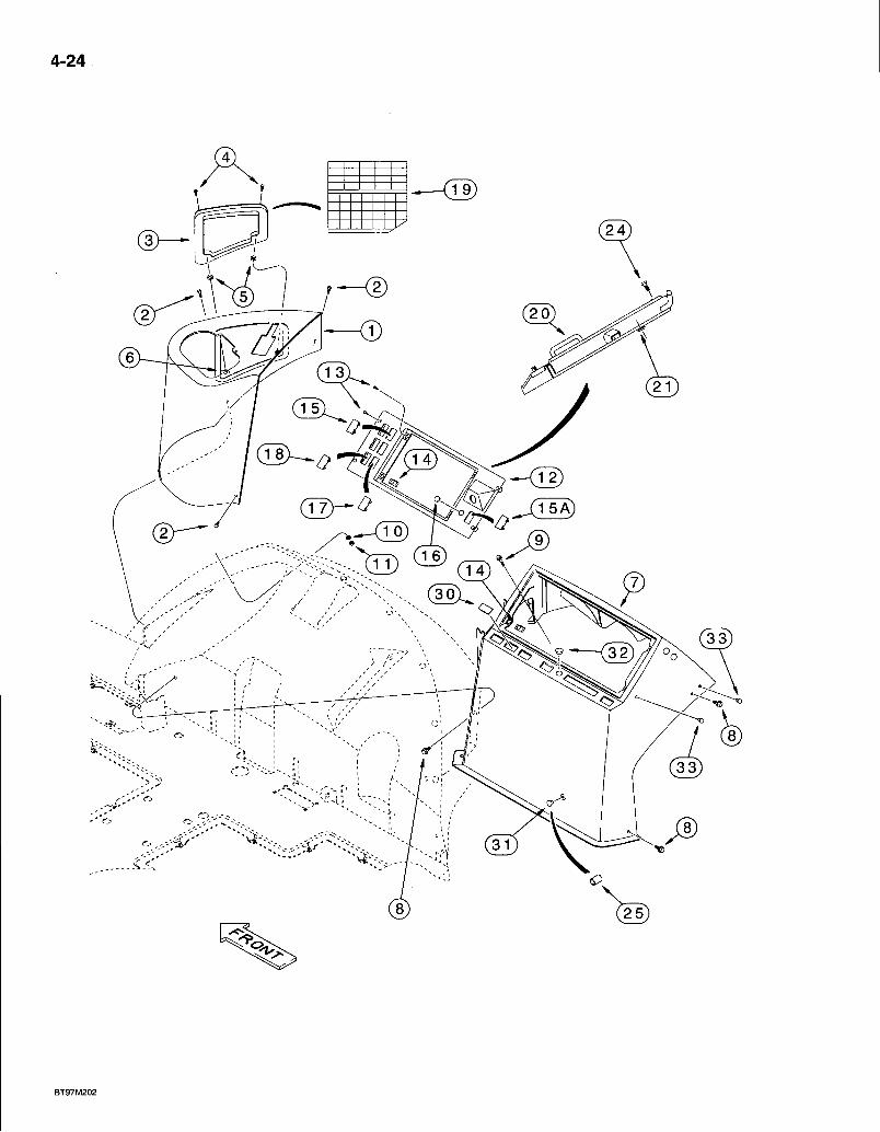
4-24
/ 1 5 A )
BT97M202
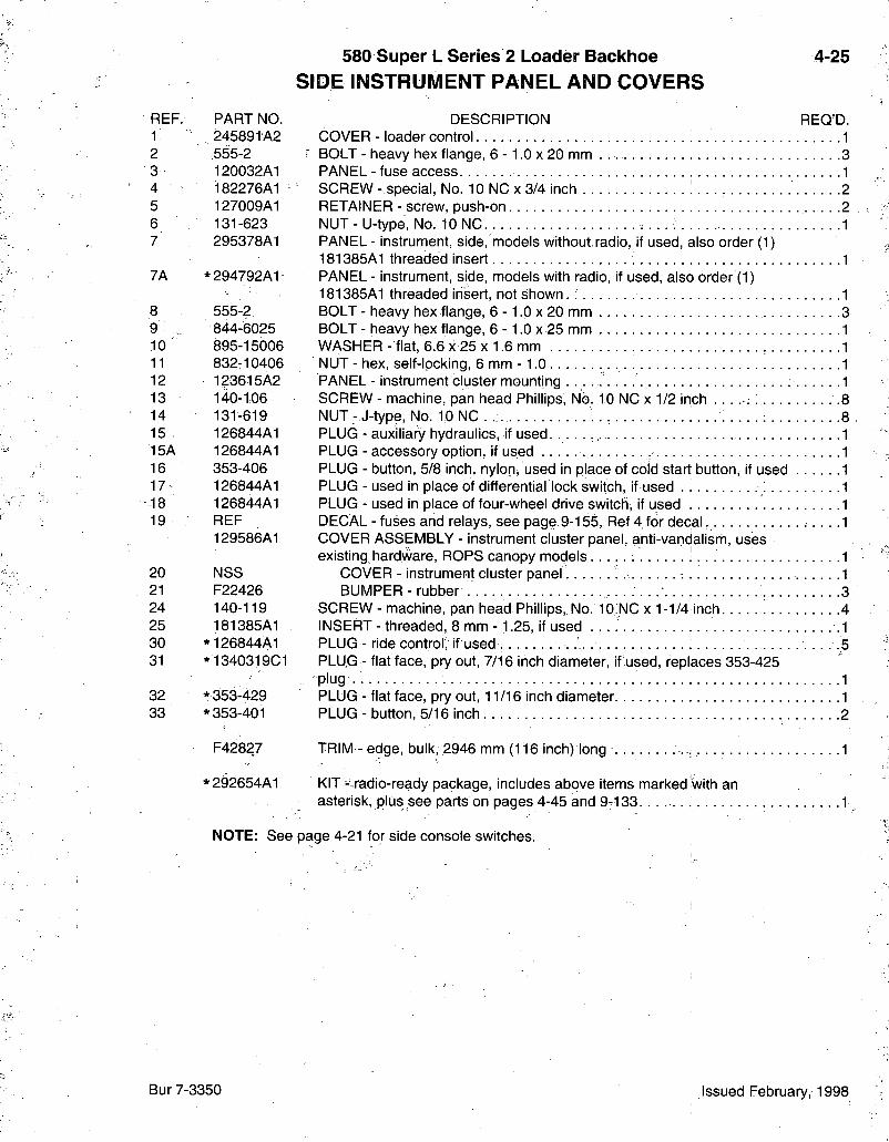
580 Super L Series 2 Loader Backhoe S I D E I N S T R U M E N T P A N E L A N D C O V E R S
4-25
REF. 1 2 3 4 5 6 7
7A
8 9 10 11 12 13 14 15 15A 16 17
•18 19
20 21 24 25 30 31
32 33
PART NO. DESCRIPTION REQ'D. 245891A2 COVER - loader control 1 .555-2 BOLT - heavy hex flange, 6 -1 .0 X 20 mm . 3 120032A1 PANEL - fuse access 1 182276A1 SCREW- special, No. 1 0 N C x 3 / 4 i n c h 2 127009A1 RETAINER - screw, push-on 2 131 -623 NUT - U-type, No. 10 NC 1 295378A1 PANEL - instrument, side, models without.radio, if used, also order (1)
181385A1 threaded insert 1 * 294792A1 PANEL - instrument, side, models with radio, if used, also order (1)
181385A1 threaded insert, not shown. .1 555-2 BOLT - heavy hex flange, 6 - 1.0 x 20 mm 3 844-6025 BOLT - heavy hex flange, 6 - 1.0 x 25 mm 1 895-15006 WASHER - flat, 6.6 x 25 x 1.6 mm 1 832-10406 NUT - hex, self-locking, 6 mm -1 .0 1 123615A2 PANEL - instrument cluster mounting 1 140-1.06 SCREW - machine, pan head Phillips, No. 10 NC x 1/2 inch .8 131-619 NUT : J-type, No. 10 NC . . . . . 8 126844A1 PLUG - auxiliary hydraulics, if used. 1 126844A1 PLUG - accessory option, if used 1 353-406 PLUG - button, 5/8 inch, nylon, used in place of cold start button, if used 1 126844A1 PLUG - used in place of differential lock switch, if used \. 1 126844A1 PLUG - used in place of four-wheel drive switch, if used 1 REF DECAL - fuses and relays, see page 9-155, Ref 4 for decal 1 129586A1 COVER ASSEMBLY - instrument cluster panel, anti-vandalism, uses
existing hardware, ROPS canopy models 1 NSS COVER - instrument cluster panel 1 F22426 BUMPER - rubber 3 140-119 SCREW - machine, pan head Phillips, No. 10;NC x 1-1/4 inch 4 181385A1 INSERT-threaded, 8 m m - 1 . 2 5 , i fused .1
* 126844A1 PLUG - ride control; if used , .5 * 1340319C1 PLUG - flat face, pry out, 7/16 inch diameter, if used, replaces 353-425
-plug 1 *353-429 PLUG - flat face, pry out, 11/16 inch diameter 1 * 353-401 PLUG - button, 5/16 inch 2
F42827 TRIM - edge, bulk, 2946 mm (116 inch) long 1
*292654A1 KIT - radio-ready package, includes above items marked with an asterisk, plus see parts on pages 4-45 and 9-133. • •1 .-
NOTE: See page 4-21 for side console switches.
Bur 7-3350 Issued February, 1998
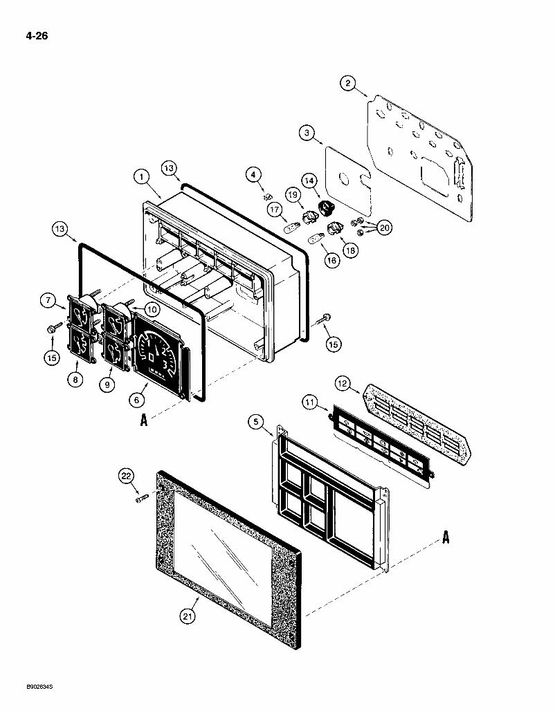
4-26
@
6
B902634S
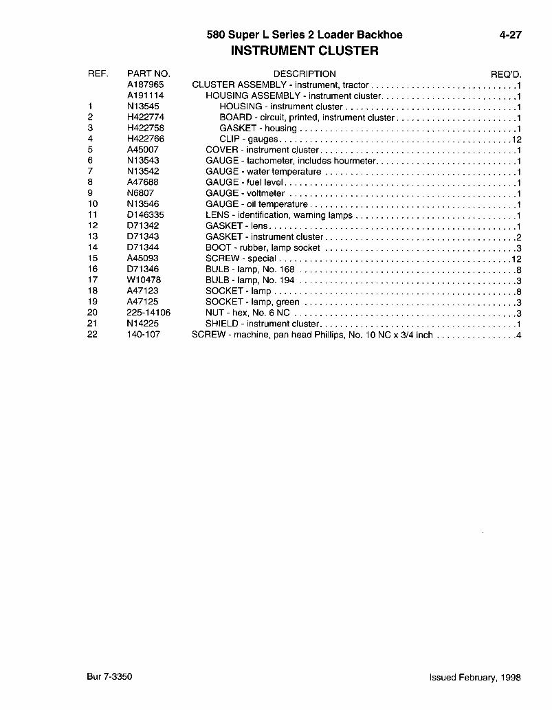
580 Super L Series 2 Loader Baclchoe I N S T R U M E N T C L U S T E R
4-27
REF. PART NO. A187965 A191114
1 N13545 2 H422774 3 H422758 4 H422766 5 A45007 6 N13543 7 N13542 8 A47688 9 N6807 10 N13546 11 D146335 12 D71342 13 D71343 14 D71344 15 A45093 16 D71346 17 W10478 18 A47123 19 A47125 20 225-14106 21 N14225 22 140-107
.1
DESCRIPTION REQ'D. CLUSTER ASSEMBLY - instrument, tractor
HOUSING ASSEMBLY - instrument cluster HOUSING - instrument cluster BOARD - circuit, printed, instrument cluster GASKET - housing CLIP - gauges
COVER - instrument cluster tachometer, includes hourmeter water temperature fuel level voltmeter oil temperature
LENS - identification, warning lamps GASKET - lens GASKET - instrument cluster 2 BOOT - rubber, lamp socket 3 SCREW - special BULB- lamp, No. 168 8 BULB - lamp, No. 194 3 SOCKET- lamp 8 SOCKET - lamp, green 3 NUT-hex . No. 6 N C 3 SHIELD - instrument cluster "I
SCREW - machine, pan head Phillips, No. 10 NC x 3/4 inch 4
GAUGE GAUGE GAUGE GAUGE GAUGE
Bur 7-3350 Issued February, 1998
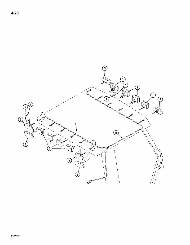
4-28
BS97M205
580 Super L Series 2 Loader Backhoe T R A C T O R L A M P E L E C T R I C A L C I R C U I T
WITH ROPS CANOPY
4-29
REF. PART NO. 1 D132681
2 D132682
3 493-11052 4 425-148 5 D135384
6 D121152 7 281^4556 8 495-31022 9 283001 A l
DESCRIPTION REQ'D. LAMP ASSEMBLY - front driving, outer, parts list page 4-33, no longer available, order ZAA7376350 lamp package 2 LAMP ASSEMBLY - flood and work, rear flood (outer) and center front and rear work lamps, parts list page 4-33, no longer available, order ZAA7376150 lamp package and ZAA8066600 mounting kit 6 WASHER - internal-external tooth lock, 1/2 inch 8 NUT - hex, jam, 1/2 inch NC 8 LAMP ASSEMBLY - turn signal and flasher, amber, front and rear, parts list page 4-37. 4 LAMP ASSEMBLY - stop and tail, red, rear, parts list page 4-37 2 SCREW - self-tapping, hex washer head. No. 10 NC x 3/8 inch .12 WASHER - flat,'7/32 x 1/2 x 3/64 inch. . 12 HARNESS - ROPS canopy, lamps, attaches to side console instrument harness, see page 9-147 for harness cover and clamps that mount to the right-hand ROPS post 1
NOTE: See side console harness page 4-19 for lamp fuses and page 4-21 for lamp switches.
Bur 7-3350 Issued February, 1998
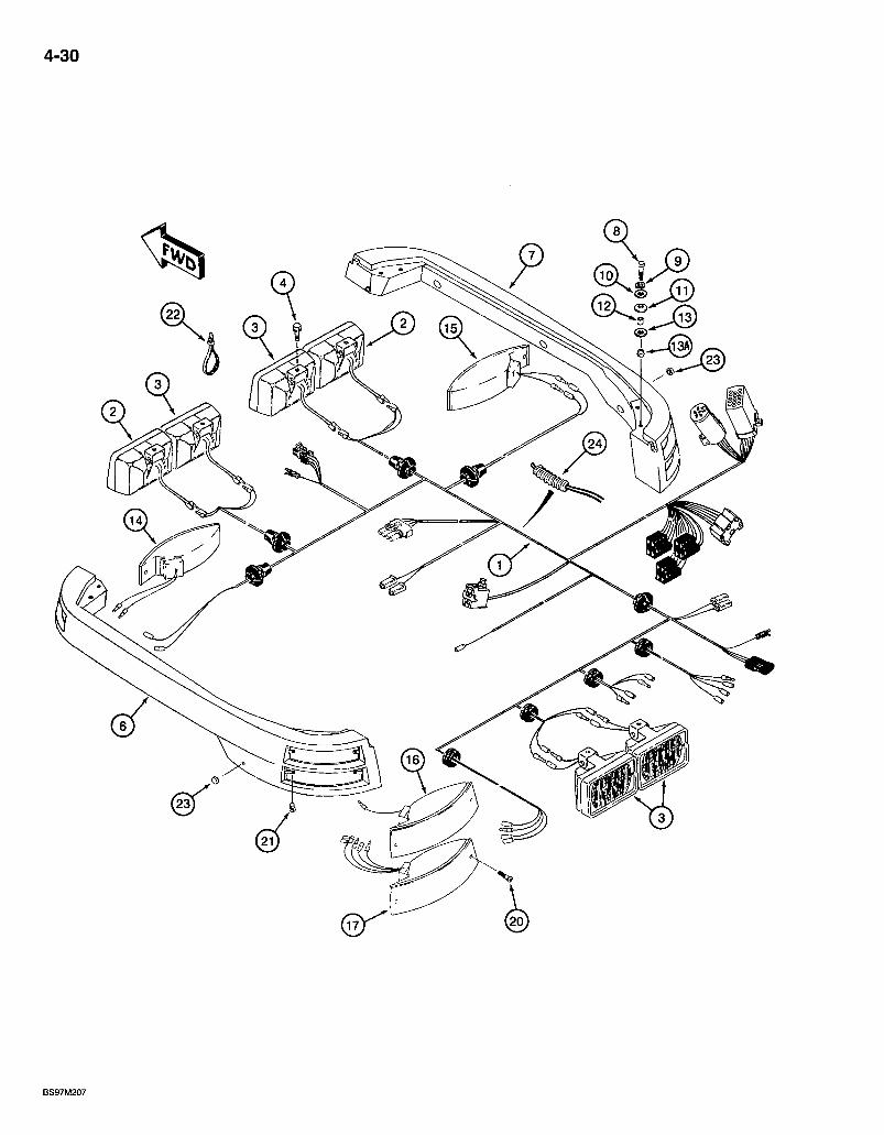
4-30
/
580 Super L Series 2 Loader Backhoe T R A C T O R L A M P E L E C T R I C A L C I R C U I T
WITH CAB
4-31
DESCRIPTION REQ'D. HARNESS - cab, models without air conditioning, attaches to side console instrument harness 1 HARNESS - cab, models with air conditioning, not shown, attaches to side console instrument harness, used in production, for service order 282017A2 cab harness (item 1) and 130876A1 adapter harness, item 27 on page 4-19 1 LAMP ASSEMBLY - front driving, parts list page 4-37 2 LAMP ASSEMBLY - flood and work, rear flood and front and rear work lamps, parts list page 4-37 :6 BOLT - hex serrated flange, 3/8 NC x 1/2 inch 8 BRACKET - left-hand lamp, includes inserts, (4) Ref 13A and (6) Ref 21 , cab models . . . , 1 BRACKET - right-hand lamp, includes inserts, (4) Ref 13A and (6) Ref 21 , cab models : 1 BOLT - hex, 8 - 1.25 x 35 mm, laihip bracket to cab frame : 8 WASHER - lock, 8 mm .8 WASHER - flat, 3/8 x 1-1/8 x 1/16 inch 8 WASHER - Belleville 8 SPACER - cab lamp bracket mounting 1 8 WASHER - flat, 9/16 x 1-3/8 x 7/64 inch 8 INSERT - threaded, 8 mm -1 .25 . . . .8 LAMP ASSEMBLY - turn signal and flasher, amber lens, left-front, parts list page 4-43 LAMP ASSEMBLY - turn signal and flasher, amber lens, right front, parts list page 4-43 LAMP ASSEMBLY - turn signal and flasher, amber lens, left rear, upper, parts list page 4-43 LAMP ASSEMBLY - stop and tail, red lens, left rear, lower, parts list page 4-43 LAMP ASSEMBLY - turn signal and flasher, amber lens, right rear, upper, not shown, parts list page 4-43 LAMP ASSEMBLY - stop and tail, red lens, right rear, lower, not shown, parts list page 4-43 SCREW - machine, pan Phillips, No. 10 NF x 1-3/4 inch, lamp to bracket 12 INSERT - No. 10 NF .12 STRAP - tie, 15 inch, nylon, retaining . .7 BUMPER - rubber .2 CONDUIT - convoluted insulation, 16 (5/8) x21 (53/64) x 889 mm (35 inch) long, windshield 1
NOTE: See side console harness-page 4-19 for lamp fuses and page 4-21 for lamp switches.
REF. • PART NO. 1 282017A2
1A 282018A2
2 109080A1 3 109081A1
4 409-768 6 187834A1
7 187836A1
8 814-8035 9 ^ 892-11008 10 495-81001 11 186756A1 12 183598A2 13 495-21056 13A 181385A1 14 131797A1
15 131796A1
16 183504A1
17 131795A1
18 183505A1
19 131794A1
20 190-105 21 181459A1 22 L18337 23 L60224 24 1202956C1
Bur 7-3350 Issued February, 1998

4-32
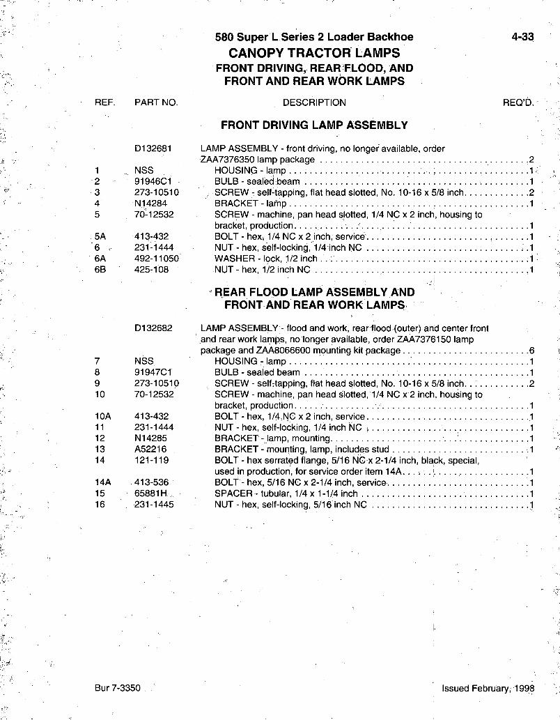
REF. PART NO.
580 Super L Series 2 Loader Backlioe C A N O P Y T R A C T O R L A M P S
FRONT DRIVING, REAR FLOOD, AND FRONT AND REAR W6RK LAMPS
DESCRIPTION
FRONT DRIVING LAMP ASSEMBLY
4-33
REQ'D.
D132681 LAMP ASSEMBLY - front driving, no longer available, order ZAA7376350 lamp package -2
1 NSS HOUSING - lamp . . . ; 1 ^ 2 91946C1 BULB - sealed beam 1 3 273-10510 SCREW - self-tapping, flat head slotted. No. 10-16 x 5/8 inch 2 4 N14284 BRACKET - lartip 1 5 70-12532 SCREW - machine, pan head slotted, 1/4 NC X 2 inch, housing to
bracket, production 1 5A 413-432 BOLT - hex, 1/4 NC x 2 inch, service . . .1 6 . 231-1444 NUT - hex, self-locking, 1/4 inch NC . = .1 6A 492-11050 WASHER - lock, 1/2 inch . . . . 1 6B 425-108 NUT-hex , 1/2 inch NC -1
REAR FLOOD LAMP ASSEMBLY AND FRONT AND REAR WORK LAMPS
7 8 9 10
10A 11 12 13 14
14A 15 16
D132682
NSS 91947C1 273-10510 70-12532
413-432 231-1444 N14285 A52216 121-119
413-536 65881H, 231-1445
LAMP ASSEMBLY - flood and work, rear flood (outer) and center front and rear work lamps, no longer available, order ZAA7376150 lamp package and ZAA8066600 mounting kit package 6
HOUSING- lamp . 1 BULB - sealed beam 1 SCREW - selfrtapping, flat head slotted. No. 10-16 x 5/8 inch. . ; 2 SCREW - machine, pan head slotted, 1/4 NC X 2 inch, housing to bracket, production. 1 BOLT - hex, 1/4.NC x 2 inch, service .1 NUT - hex, self-locking, 1/4 inch NC •. 1 BRACKET- lamp, mounting 1 BRACKET - mounting, lamp, includes stud .1 BOLT - hex serrated flange, 5/16 NG x 2-1/4 inch, black, special, used in production, for service order item 1 4 A . . . . . .- 1 BOLT - hex, 5/16 NC x 2-1/4 inch, service .1 SPACER - tubular, 1/4 x 1-1/4 inch 1 NUT - hex, self-locking, 5/16 inch NC .1
Bur 7-3350 Issued February, 1998
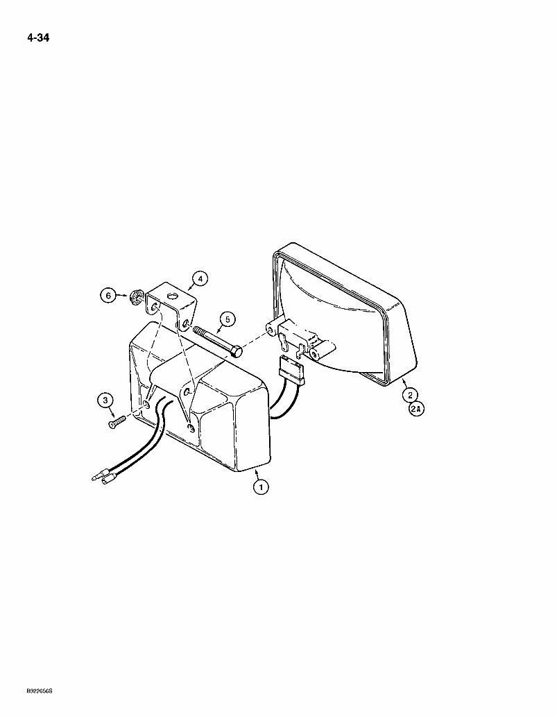
4-34
B922656S
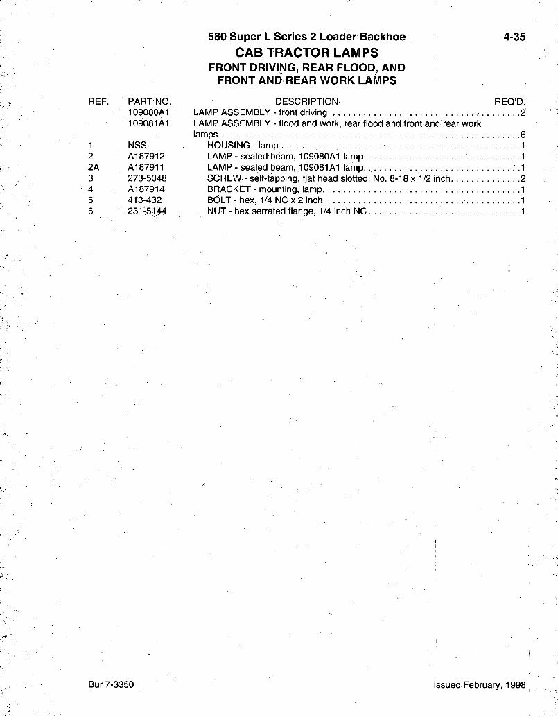
580 Super L Series 2 Loader Backhoe CAB TRACTOR LAMPS
FRONT DRIVING, REAR FLOOD, AND FRONT AND REAR WORK LAMPS
4-35
REF. PART NO 109080A1 109081A1
1 NSS 2 A187912 2A A187911 3 273-5048 4 A187914 5 413-432 6 231-5144
DESCRIPTION REQ'D. LAMP ASSEMBLY - front driving . . . .2 LAMP ASSEMBLY - flood and work, rear flood and front and rear work lamps 6
HOUSING- lamp 1 LAMP-sealed'beam, 109080A1 lamp 1 LAMP - sealed beam, 109081A1 lamp. .1 SCREW - self-tapping, flat head slotted, No. 8-18 x 1/2 inch 2 BRACKET - mounting, lamp 1 BOLT - hex, 1/4 NC x 2 inch 1 NUT - hex serrated flange, 1 /4 inch NC 1
Bur 7-3350 Issued February, 1998
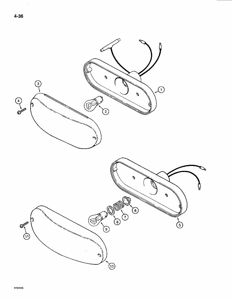
4-36
870040S

REF. PART NO.
580 Super L Series 2 Loader Backhoe CANOPY TRACTOR LAMPS
STOP AND TAIL LAMPS AND TURN SIGNAL AND FLASHER LAMPS
DESCRIPTION
STOP AND TAIL LAMP
4-37
REO'D.
D121152 LAMP ASSEMBLY - stop and tail, red • • -2 1 NSS BODY - lamp, complete 1 2 T34857 BULB - lamp. No. 1157, stop and tall 1 3 N6836 LENS - red, lamp 1 4 261-14310 SCREW - self-tapping, pan Phillips, No. 6 NC X 5/8 inch 2
TURN SIGNAL AND FLASHER
D135384 LAMP ASSEMBLY - turn signal and.flasher, amber 5 NSS BODY AND SOCKET - lamp 6 NSS SEAL - rubber, spring retaining 7 NSS SPRING - lamp. . 8 NSS INSULATOR- lamp
' 9 A41264 BULB - lamp, 12 volt. No. 1156, turn signal and flasher 10 N14283 LENS - amber, lamp 11 261-14310 SCREW - self-tapping, pan Phillips, No. 6 NC x 5/8 inch
Bur 7-3350 Issued February, 1998
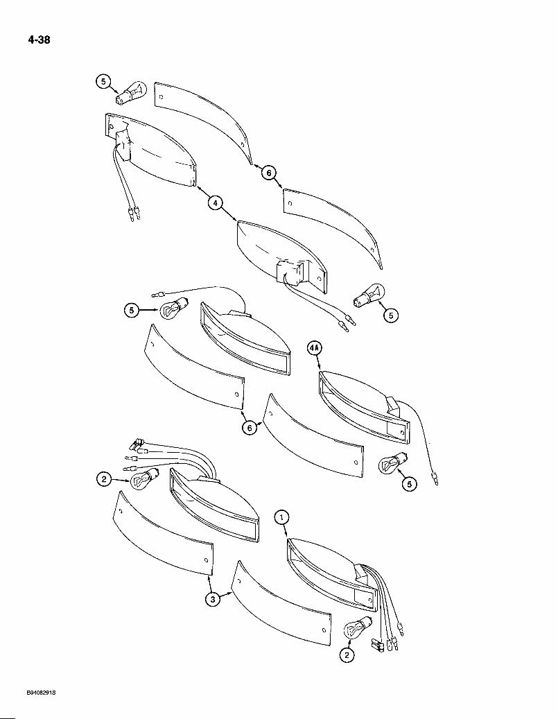
4-38
REF.
1 2 3
PART NO.
131794A1 131795A1 NSS T34857 183749A1
580 Super L Series 2 Loader Backhoe CAB TRACTOR LAMPS
STOP AND TAIL LAMPS AND TURN SIGNAL AND FLASHER LAMPS
DESCRIPTION
STOP AND TAIL LAMP
LAMP ASSEMBLY - stop and tail, red-lens, right rear,-lower LAMP ASSEMBLY - stop and tail, red lens, left rear, lower^.
BODY - lamp, complete BULB - lamp, No. 1157, stop and tail LENS - lamp, red
4-39
REQ'D.
4 4A 5 6
TURN SIGNAL AND FLASHER i ' ' •'
131796A1 LAMP ASSEMBLY - turn signal and flasher, amber lens, right front 183505A1 LAMP ASSEMBLY - turn signal and flasher, amber lens, right rear, upper. 131797A1 LAMP ASSEMBLY - turn signal an'd flasher, amber lens, left front 183504A1 LAMP ASSEMBLY - turn signal and flasher, amber lens, left rear, upper. . NSS BODY- 131796A1 or131797A1 lamp NSS BODY - 183504A1 or 183505A1 lamp A41264 BULB - lamp, 12 volt. No. 1156, turn signal and flasher 183748A1 LENS - lamp, amber
Bur 7-3350 Issued February, 1998
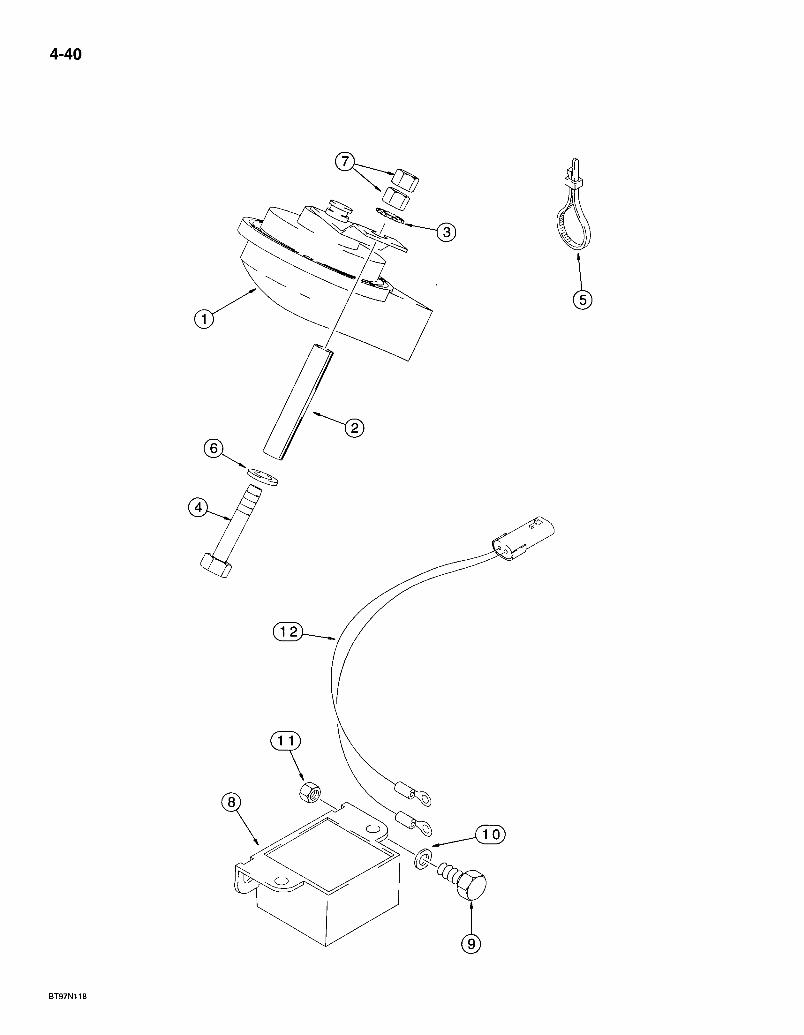
4-40
BT97N118
REF. PART NO.
580 Super L Series 2 Loader Backhoe HORN AND BACKUP ALARM
DESCRIPTION
HORN
4-41
REQ'D.
1 190155A1 " HORN - 1 2 volt, includes mounting bracket . 1 2 116423A1 SPACER - split 1 3 893-11008 WASHER - external tooth lock, 8 mm 1 4 814-8110 BOLT - hex, 8 -1.25 x 110 mm 1 5 LI 8337 STRAP- t ie , 15 inch 2 6 895-11008 WASHER - flat, 9 x 1 7 x 1 . 6 mm, if used 1 7 - 829-1408 NUT - hex, 8 mm -1.25, class 10, if used :2
BACKUP ALARM
8 109511A1 ALARM - backup, attaches to main engine harness, see page 4-11 for engine harness options 1
9 614-8025 BOLT - hex, full threads, 8 - 1.25 x 25 mm 2 10 895-11008 WASHER-f la t , 9 x 1 7 x 1 . 6 m m 2 11 832-10408 NUT - hex, self-locking, 8 mm -1.25 ' 2 12 D139175 WIRE - pigtail, attaches main engine harnessto alarm. 1
NOTE: See front console instrument harness page 4-17 for horn switch.
Bur 7-3350 Issued February, 1998

4-42
B9408269T
580 Super L Series 2 Loader Backhoe 4-43 ROTATING BEACON
USED ON CAB OR CANOPY MODELS
REF. PART NO. DESCRIPTION REQ'D. 1 A23870 GROMMET-wi re 1 2 493-11026 WASHER - internal-external tooth lock, 1/4 inch, ground 1i 3 495-21031 WASHER-f la t , 5 / 1 6 x 3 / 4 x 1 / 1 6 inch, ground 1 4 108366A1, BEACON ASSEMBLY - rotating, attaches to cab or canopy harness 1 5 A187542 LENS - beacon, amber, if used 1 6 127158A1 LENS - beacon, blue, if used 1 7 168-71 SCREW - drive, round head. No. 8 x 1/2 inch, lens mounting 3 8 238-5005 O-RING - 3/32 ID x 1/16 inch wide, lens mounting screw 3 9 ••*• - 101531A1 CLIP-.bulb.- 1i 10 3125705R1 LAMP- beacon, 12 volt, 55 watt t 11 A1875t5 BELT - drive motor, rotating beacon . . . 1 12 NSS BASE - with drive motor 1 13 614-6020 BOLT - hex, full threads, 6 -1 .0 x 20 mm 3 14 136-54 PIN - cotter, hair, 1/4 x 11/16 inch, bolt retaining 3
NOTE: See side console instrument harness page 4-21 for beacon switch and page 4-19 for fuse.
Bur 7-3350 Issued February, 1998
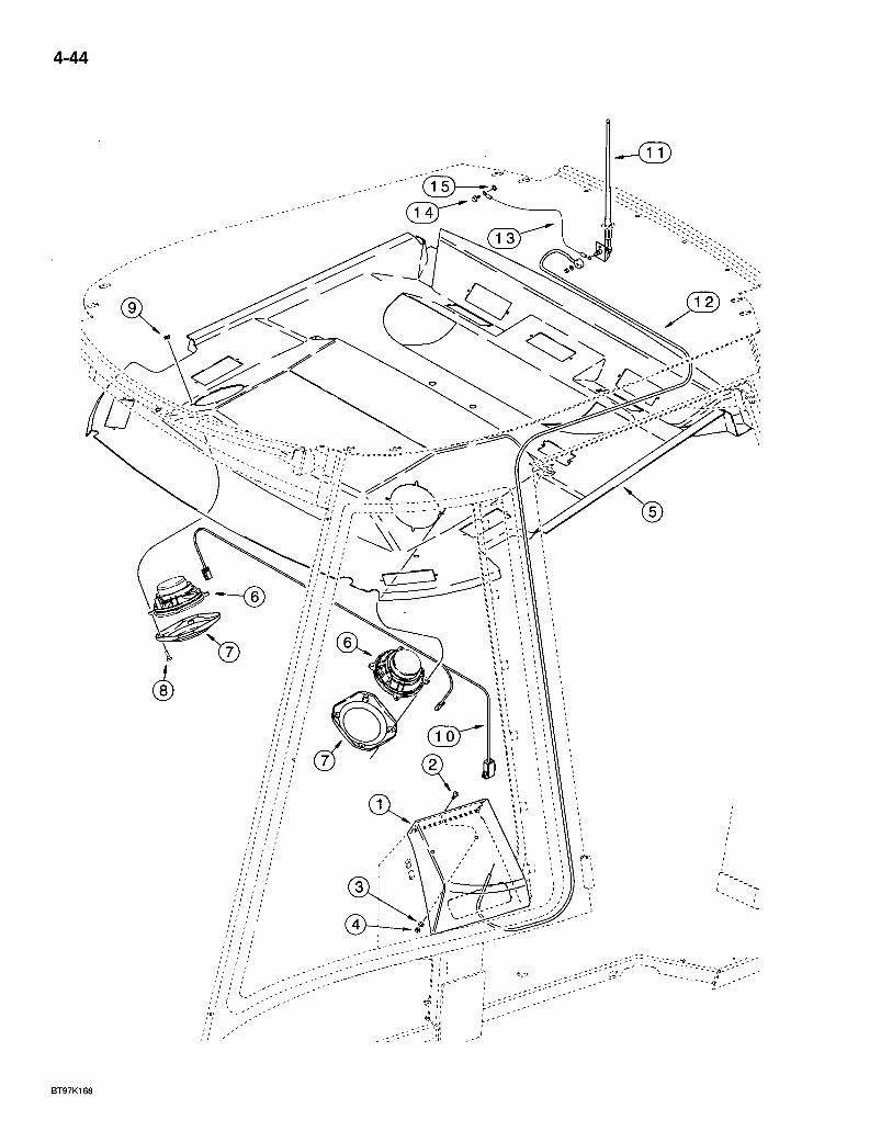
4-44
1 4J[
BT97K168
580 Super L Series 2 Loader Backhoe *RADIO, MOUNTING BOX, ANTENNA AND S P E A K E R S
4-45
REF. PART NO. *292654A1
1 221418A1 2 161-115 ' 3 495-11028 4 231-1444 5 300157A1
6 i82721A2 7 " 187281A1 8 . . 7 6 1 - 1 7 3 2 5 9 177269A1 10 298228A1 11 197745A1
12 284549A1 13 291010A1
14 760-14413 15 893-11005
DESCRIPTION REO'D. KIT - radio-ready package, also includes right-hand side instrument panel, see page 4-25 1
BOX - radio mounting 1 SCREW - hex socket button head, 1/4 NC x 3/4 inch 2 WASHER - flat, 9/32 x 5/8 x 1/16 inch 2 NUT - hex, self-locking, 1/4 inch NC 2 HEADLINER ASSEMBLY - cab, models with radio-ready package, see page 9-133 for headliner components. 1 SPEAKER - radio, 5-1/4 inch, round 2 GRILLE - speaker cover . .2 SCREW - self-tapping, pan Phillips, 4.2 -1 .4 x 25 mm 8 NUT - U-type, spring 8 HARNESS-speaker 1 ANTENNA - radio, includes flat washer and nut which are not serviced separately ., . -1 CABLE - antenna 1 WIRE - antenna ground, ground eyelet must be mounted on cab side of antenna cable or am radio will not operate 1 SCREW - self-tapping, pan Phillips, 4.8 -1 .8 x 13 mm .1 WASHER - external tooth lock, 5 mm 1
* N O T E : Does not include radio. For headliner used on models with the radio-ready kit, see page 9-133.
Bur 7-3350 Issued February, 1998
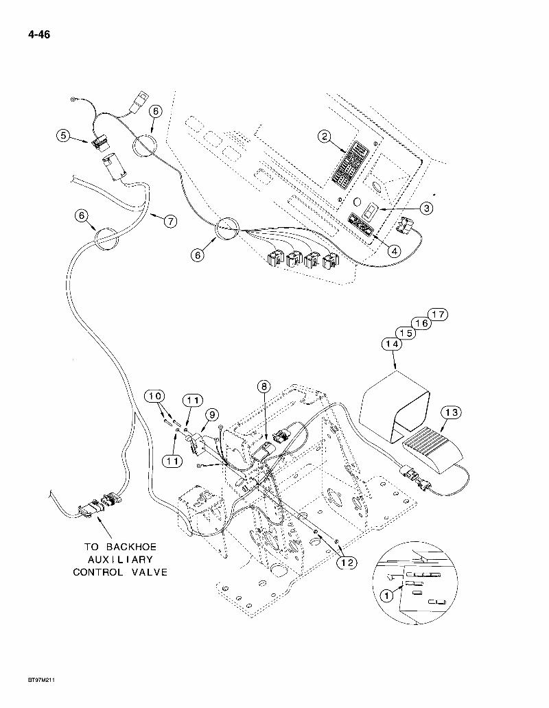
4-46
T O B A C K H O E A U X I L I A R Y
C O N T R O L V A L V E
580 Super L Series 2 Loader Backhoe BACKHOE AUXILIARY HYDRAULIC ELECTRICAL CIRCUIT
4-47
REF. PART NO. DESCRIPTION REQ'D. 1 . ' 121.4,13A1 FUSE - mini, 15 ampere 1 2 . 284479A1 DECAL - backhoe auxiliary hydraulics, hi flow/low flow. . . : .1 3 284058A1 SWITCH - rocker.'^backhoe auxiliary hydraulics, mounts below key s w i t c h . . . . . .1 4 284627A1 DECAL - backhoe auxiliary hydraulics, low flow - light on/hi flow - light off 1 5 296508A2 HARNESS - side console options, attaches to side console harness and
chassis options harness 1 6 L18337 STRAP- t ie , 15 inch 4 7 302803A1 HARNESS - chassis options 1 8 298681A1 HARNESS - pigtail, detent lever .,. 1 9 D137363 SWITCH - contact, limit 1 10 440-10616 SCREW - machine, pan Phillips, No. 6 NC x 1 inch 2 11 895-11004 WASHER - flat, 4.4 x 9 x 0.8 mm 2 12 193-1003 NUT - hex, with external tooth lock washer, No. 6 NC 2 13 137219A1 SWITCH - foot, backhoe auxiliary hydraulics 1 14 300030A1 GUARD - foot switch 1 15 843-1516 SCREW-machine, flat Phillips, 5 - 0 . 8 x 1 6 mm . . 2 16 892-11005 WASHER - lock, 5 mm . . . . .- 2 17 824-1405 NUT-hex , 5 m m - 0 . 8 . 2
NOTE: See pages 8-51 - 8-55 for backhoe auxiliary hydraulics, page 9-43jfor auxiliary control lever and page 9-25 for the backhoe control tower cover used with auxiliary hydraulics.
Bur 7-3350 Issued February, 1998
580 Super L Series 2 Loader Backhoe 5-1
ALPHABETICAL INDEX STEERING
DESCRIPTION PAGE
Axle and Spindles 5-15 Column - Steering 5-9 Cylinder - Two Wheel Drive 5-13 Hub and Bearings 5-17 Hydraulic Circuit 5-5,5-7 Valve - Steering Control 5-11 Wheel - Steering 5-3 Wheels and Tires 5-19
Bur 7-3350 Issued February, 1998
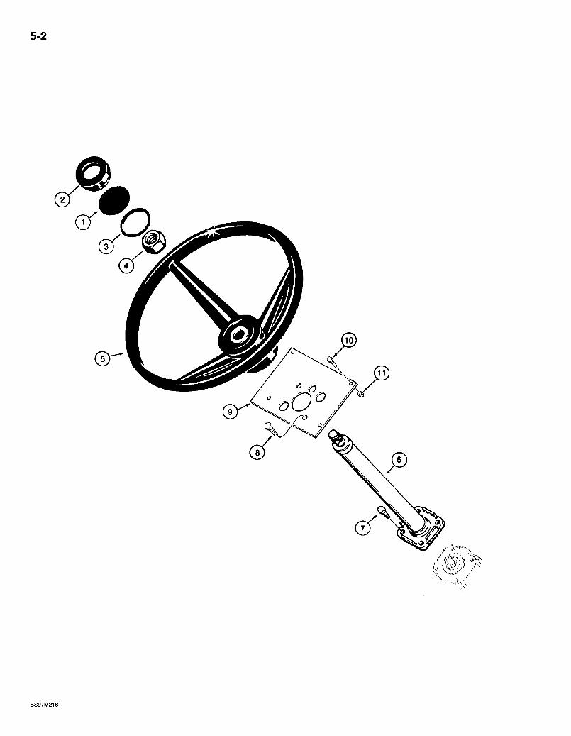
5-2
BS97M216
580 Super L Series 2 Loader Backhoe STEERING WHEEL AND STEERING COLUMN
5-3
REF. PART NO. DESCRIPTION REQ'D. 1 1342054C1 INSERT - plastic, black . . . . 2 114882A1 CAP - steering wheel. 3 238-5227 0-RING - 2-1/8 ID x 1/8 inch wide, cap 4 1959509C1 NUT - lock, special, steering wheel retaining 5 A65544 WHEEL - steering, tractor 6 142930A1 COLUMN ASSEMBLY - steering, parts list page 5-9 7 614-10020 BOLT - hex, full threads, 10 -1.5 x 20 mnn 2 8 614-10030 BOLT - hex, full threads, 10 -1.5 x 30 mnri . . .2 9 183085A2 PLATE - mounting, steering column 1 10 614-8020 BOLT - hex; full threads, 8 - 1.25 x 20 mm . . 4 11 829-1408 NUT-hex, 8 mm - 1.25, class 10 -4
NOTE: .See page .4-17 for turn signal rocker switch.
Bur 7-3350 Issued February, 1998
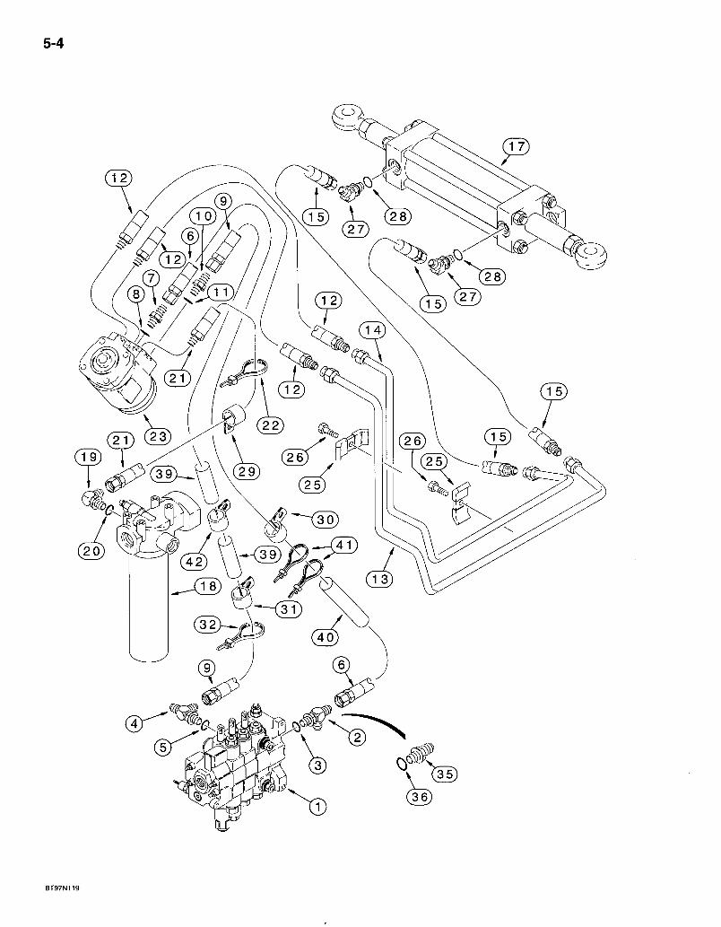
5-4
BT97N119
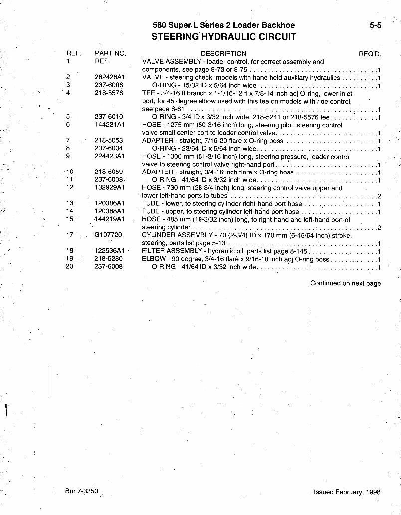
580 Super L Series 2 Loader Backhoe STEERING HYDRAULIC CIRCUIT
5-5
REF. PART NO. 1 REF
2 282428A1 3 237-6006 4 218-5576
5 237-6010 6 144221A1
7 218-5053 8 237-6004 9 224423A1
10 218-5059 11 237-6008 12 132929A1
13 120386A1 14 120388A1 15 - 144219A1
17 G107720
18 122536A1 19 218-5280 20 237-6008
DESCRIPTION REQ'D. VALVE ASSEMBLY - loader control, for correct assembly and components, see page 8-73 or 8-75 1 VALVE - steering check, models with hand held auxiliary hydraulics 1
0-RING -15/32 ID x 5/64 inch wide 1 TEE - 3/4-16 fl branch x 1-1/16-12 fl x 7/8-14 inch adj 0-ring, lower inlet port, for 45 degree elbow used with this tee on models with ride control, see page 8-61 1
0-RING - 3/4 ID X 3/32 inch wide, 218-5241 or 218-5576 tee 1 HOSE - 1275 mm (50-3/16 inch) long, steering pilot, steering control valve small center port to loader contt-ol valve. 1 ADAPTER - straight, 7/16-20 flare x 0-ring boss . 1
6-RING - 23/64 ID x 5/64 inch wide. 1 HOSE - 1300 mm (51-3/16 inch) long, steering pressure, loader control valve to steering control valve right-hand port. . . ; 1 ADAPTER - straight, 3/4-16 inch flare x 0-ring boss 1
0-RING - 41/64 ID x 3/32 inch wide 1 HOSE - 730 mm (28-3/4 inch) long, steering control valve upper and lower left-hand ports to tubes 2 TUBE - lower, to steering cylinder right-hand port hose 1 TUBE - upper, to steering cylinder left-hand port hose . . . i , 1 HOSE - 485 mm (19-3/32 inch) long, to right-hand and left-hand port of steering cylinder 2 CYLINDER ASSEMBLY - 70 (2-3/4) ID x 170 mm (6-45/64 inch) stroke, steering, parts list page 5-13 1 FILTER ASSEMBLY - hydraulic oil, parts list page 8-145 1 ELBOW - 90 degree, 3/4-16 flare" x 9/16-18 inch adj O-ring boss 1
0-RING - 41/64 ID x 3/32 inch wide 1
Continued on next page
Bur 7-3350 Issued February, 1998
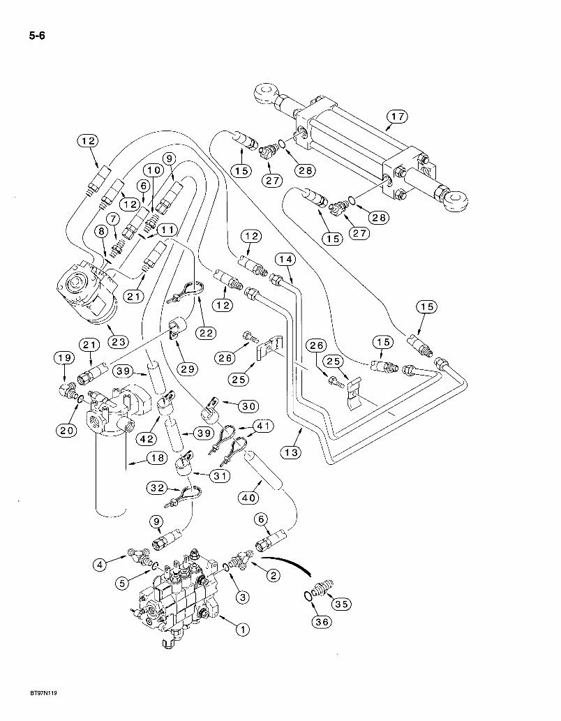
5-6
( 13 )
BT97N119
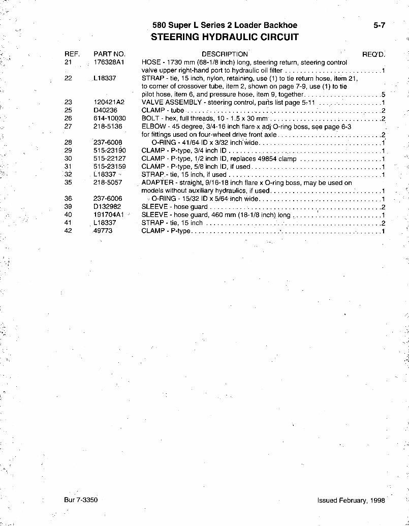
580 Super L Series 2 Loader Backhoe STEERING HYDRAULIC CIRCUIT
5-7
REF. 21
22
23 25 26 27
28 29 30 31 32 35
36 39 40 41 42
PART NO. 176328A1
LI 8337
120421A2 D40236 614-10030 218-5136
237-6008 515r23190 515-22127 515-23159 LI 8337 218-5057
237-6006 D132982 191704A1 LI 8337 49773
DESCRIPTION REQ'D. HOSE - 1730 mm (68-1/8 inch) long, steering return, steering control valve upper right-hand port to hydraulic oil filter 1 STRAP - tie, 15 inch, nylon, retaining, use (1) to tie return hose, item 21, to corner of crossover tube, item 2, shown on page 7-9, use (1) to tie pilot hose, item 6, and pressure hose, item 9, together 5 VALVE ASSEMBLY - steering control, parts list page 5-11 1 CLAMP-tube 2 BOLT-hex, full threads, 10-1 .5x30 mm . . 2 ELBOW - 45 degree, 3/4-16 inch flare x adj O-ring boss, see page 6-3 for fittings used on four-wheel drive front axle 2
O-RING - 41/64 ID x 3/32 inch"wide 1 CLAMP - P-type, 3/4 inch ID 1 CLAMP - P-type, 1/2 inch ID, replaces 49854 clamp . 1 CLAMP - P-type, 5/8 inch ID, if used 1 STRAP - tie, 15 inch, if used 1 ADAPTER - straight, 9/16-18 inch flare x 0-ring boss, may be used on models without auxiliary hydraulics, if used ' 1
. O-RlNG -15/32 ID x 5/64 inch wide. 1 SLEEVE - hose guard 2 SLEEVE - hose guard, 460 mm (18-1/8 inch) long 1 STRAP-tie, 15 inch 2 CLAMP-P-type ' 1
Bur 7-3350 Issued February, 1998
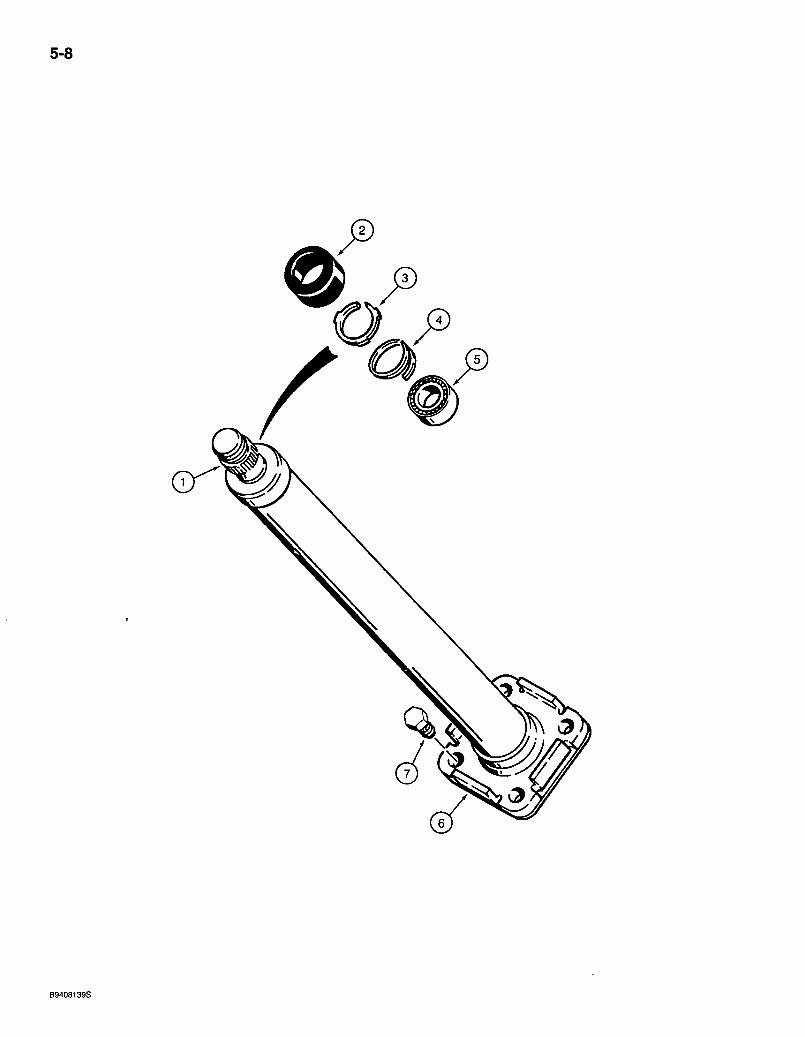
5-8
B9408139S
580 Super L Series 2 Loader Backhoe STEERING COLUMN
5-9
REF. PART NO. DESCRIPTION REQ'D. 142930A1 COLUMN ASSEMBLY - steering 1
1 NSS COLUMN - steering shaft 1 2 S115351 CAP-shaft 1 3 NSS RETAINER - bearing 1 4, 102-1387 RING - external spiral retaining, No. 87, bearing .1 5 L30881 BEARING - roller, steering shaft 1 6 NSS FLANGE-tube 1 7 614-10020 BOLT - hex, full threads, 10 -1.5 x 20 mm . . : 2
Bur 7-3350 Issued February, 1998
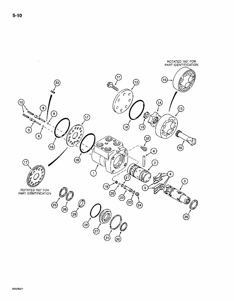
5-10
ROTATED 180* FOR PART IDENTIFICATION
ROTATED 180' FOR PART IDENTIFICATION
BS97B271
580 Super L Series 2 Loader Backhoe STEERING CONTROL VALVE
5-11
REF. PART NO. 120421A2
1 #NSS 2 NSS 3 NSS
N14250 4 L30889 5 NSS 6 L30888 8 211-1006 9 136494A1 10 - ^ N14763 . 11 143717A1 12 135867A1 13 , 143723A1
143721A1 14 NSS 15 NSS 16 L30878 •17 135869A1 18 *.238-5040 19 L35368 20 211-1010 21 * L3d893 22 D82806 23 * 238-5012 24 D82805 25 G13609 26 D82804 27 S110170 28 * 238-5225 29 *NSS 30 *697494R91 31 S110169 32 NSS 33 196087A1
DESCRIPTION REQ'D. VALVE ASSEMBLY - steering control
HOUSING - control valve SLEEVE - control valve SPOOL - control valve KIT - centering spring
SPRING - spool, centering, 6 in kit, order N14250 kit. 4 SPACER - spring 2
PIN - roll, centering • • -I BALL - chrome alloy steel, 3/16 inch, grade 24, anticavitation .2 •RETAINER - spring, anticavitation 2 -SPRING - anticavitation 2 BOLT -12 point flange, special, 5/16 NC x 2 inch 7 CAP - end; without O-ring groove SPACER - gerotor, drive shaft GEROTOR - pump, control valve
ROTOR - control valve .'. STATOR - control valve
SHAFT - drive, gerotor, steering control valve PLATE - spacer, with.O-ring groove O-RING - 2-7/8 ID x 1/16 inch wide, cover and housing 3 RETAINER - check ball BALL - chrome alloy steel, 5/16 inch, grade 24, check O-RING - 7/16 inch ID, seat, inner SEAT-ball, check O-RING - 3/8 ID X 1/16 inch wide, seat, outer. SCREW - set, hex socket, special BEARING - needle; spool RACE - thrust, bearing, bearing GLAND - seal, spool, seal O-RING -1-7/8 ID X 1/8 inch wide, seal retainer SEAL - spool, inner SEAL -1 inch ID, spool, outer RING - retaining, seal -VALVE ASSEMBLY - relief, factory preset, do not remove SPRING - detent, check ball . . . ; 2
* 1343658C3 KIT - seal, low torque, includes above items marked with an asterisk 1 -
#NOTE: Housing may have a 5/16 - 24 inch hole tapped next to the center hole (steering pilot pressure). The 5/16 inch hole has a Parker Hannifin fitting #2 hp50n-2 installed in it. This is a hollow hex straight thread O-ring plug. The plug must be purchased from Parker Hannifin with the O-ring or use 218-5205 plug with 237-6002 O-ring.
Bur 7-3350 Issued February, 1998
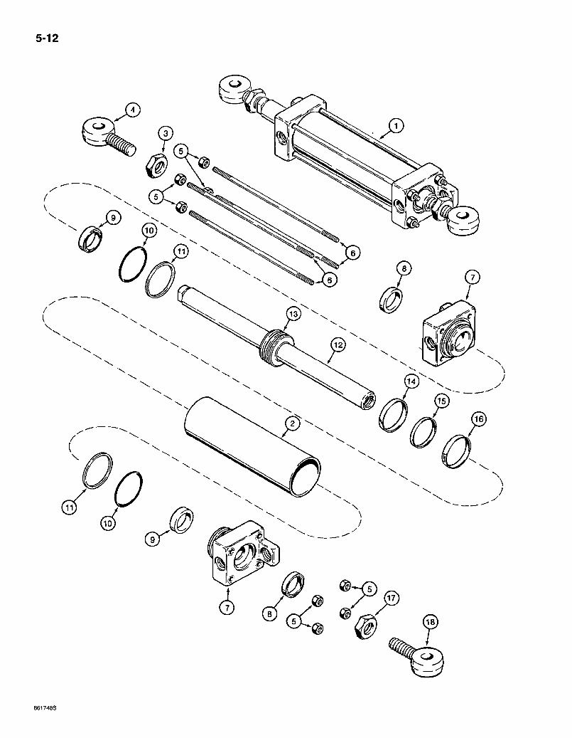
5-12
0
0 0
861748S

REF. PART NO. 1 0107720
2 G106808 3 129-369 4 G106832 5 425-106 6 0106817 7 0106810 8 **D95142 9 **0107921 10 * * 238-5230 11 * * 032129
0107721 12 NSS 13 NSS 14 **0105187 15 * * 0104439 16 * * 0104454 17 . 425-1514 18 0106813
>** 0110045
580 Super L Series 2 Loader Backhoe STEERING CYLINDER
*TWO WHEEL DRIVE FRONT AXLE
DESCRIPTION CYLINDER ASSEMBLY - 70 (2-3/4) ID x 170 mm (6-45/64 inch) stroke, see footnote, steering, two wheel drive front axle .
TUBE - cylinder NUT - hex, jam, left-hand thread, 7/8 inch NF EYE - rod, left-hand thread NUT - hex, 3/8 inch NO ROD - tie, 338 mm (13-5/16 inch) long, cylinder OLAND - cylinder WIPER - piston rod, outer SEAL - U-cup, piston rod, wide, with 0-ring 0-RINO - 2-1/2 ID X 1/8 inch wide, gland RING - backup, gland O-ring ROD ASSEMBLY - piston, 38 mm (1-1/2 inch) diameter
ROD - piston . . PISTON - cylinder
RING - wear, piston : RING - seal, inner SEAL - piston, expandable, outer. NUT - hex, jam, 7/8 inch NF EYE - rod, right-hand thread
5-13
REQ'D.
KIT - seal, includes all items with an asterisk
NOTE:' The cylinder assembly part number is stamped on some cylinder glands or tubes.
* NOTE: See page 6-9 for the four-wheel drive front axle steering cylinder.
Bur 7-3350 Issued February, 1998
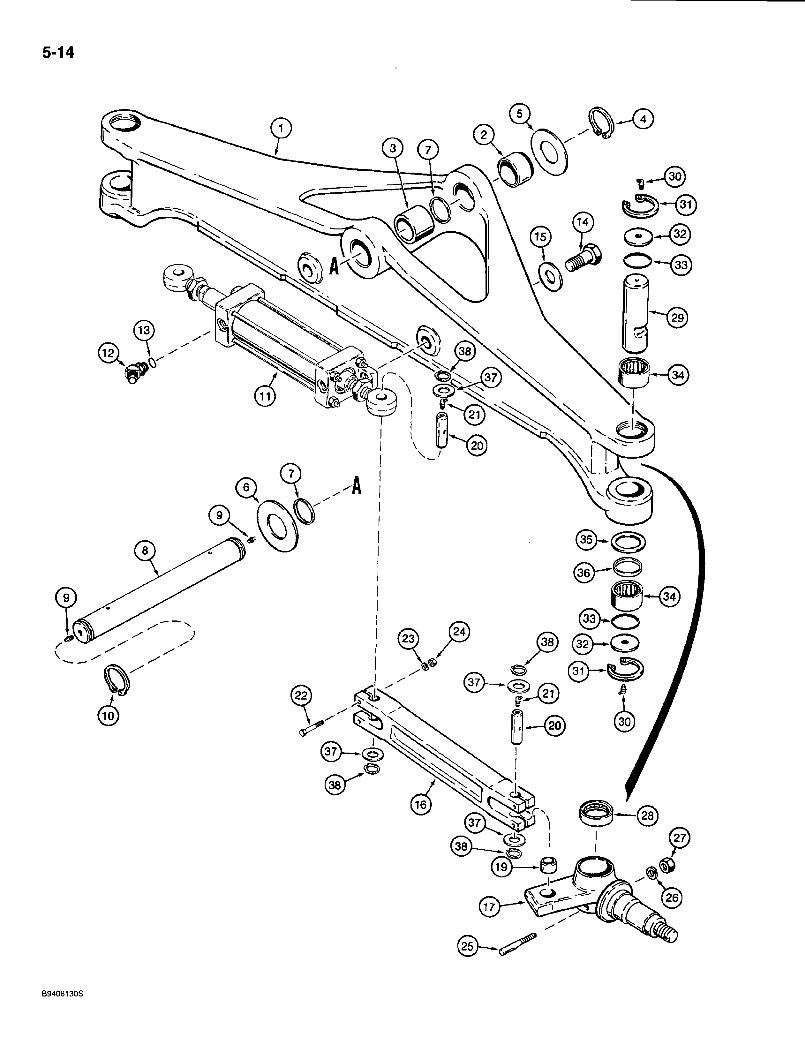
5-14
5 ®
© (31)—
®
B9408130S
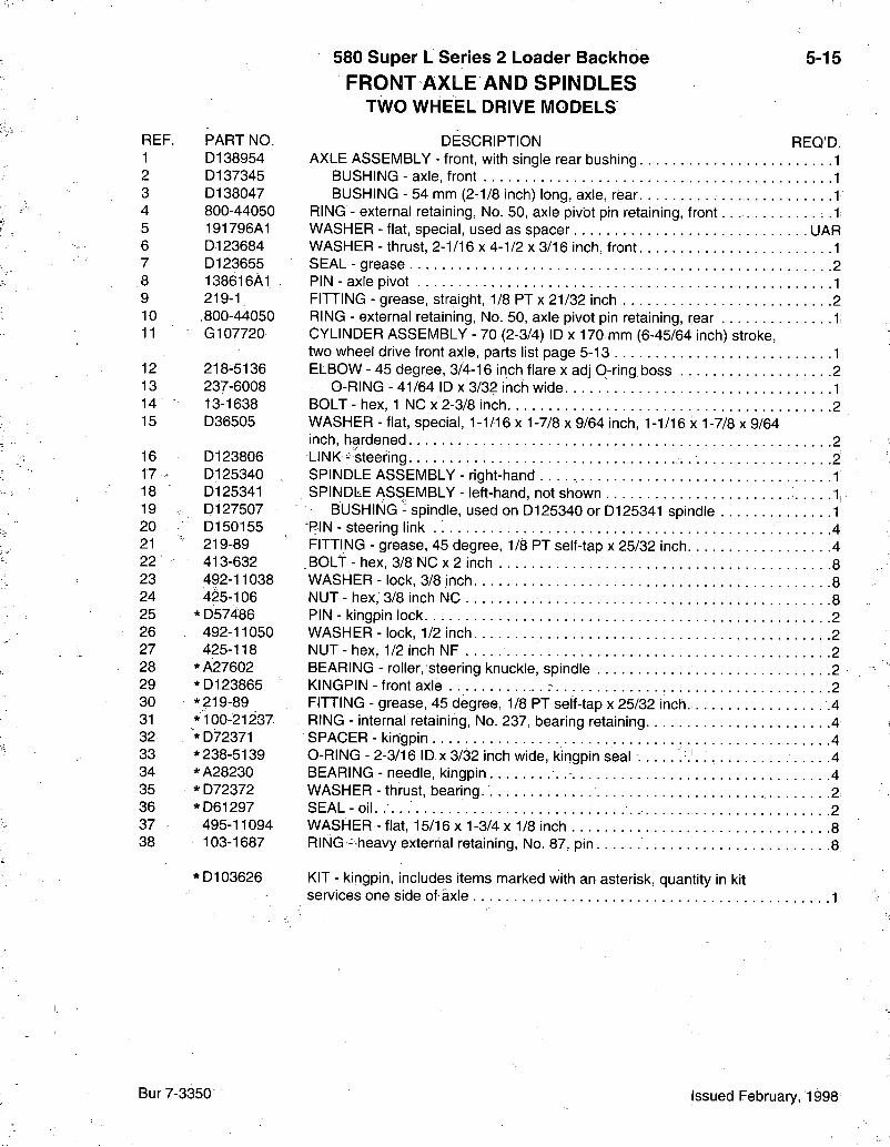
580 Super L Series 2 Loader Backhoe FRONT AXLE AND SPINDLES
TWO W H E E L DRIVE MODELS
5-15
REF. PART NO. 1 D138954 2 D137345 3 D138047 4 800-44050 5 191796A1 6 D123684 7 D123655 8 138616A1 9 219-1 10 .800-44050 11 G107720
12 218-5136 13 237-6008 14 13-1638 15 D36505
16 D123806 17 > D125340 18 D125341 19 . D127507 20 D150155 21 219-89 22 413-632 23 492-11038 24 425-106 25 * D57486 26 492-11050 27 425-118 28 *A27602 29 *D123865 30 * 219-89 31 * 100-21237 32 * D72371 33 * 238-5139 34 *A28230 35 * D72372 36 *D61297 37 495-11094 38 103-1687
*D103626
DESCRIPTION REQ'D. AXLE ASSEMBLY - front, with single rear bushing 1
BUSHING - axle, front 1 BUSHING - 54 mm (2-1/8 inch) long, axle, rear 1
RING - external retaining, No. 50, axle pivot pin retaining, front : .1 WASHER - fiat, special, used as spacer UAR WASHER - thrust, 2-1/16 x 4-1/2 x 3/16 inch, front 1 SEAL - grease 2 PIN - axle pivot 1 FITTING - grease, straight, 1/8 PT x 21/32 inch .2 RING - external retaining, No. 50, axle pivot pin retaining, rear 1 CYLINDER ASSEMBLY - 70 (2-3/4) ID x 170 mm (6-45/64 inch) stroke, two wheel drive front axle, parts list page 5-13 1 ELBOW - 45 degree, 3/4-16 inch flare x adj 0-ring boss 2
0-RING - 41/64 ID x 3/32 inch wide 1 BOLT - hex, 1 NC x 2-3/8 inch 2 WASHER - flat, special, 1-1/16 x 1-7/8 x 9/64 inch, 1-1/16 x 1-7/8 x 9/64 inch, hardened 2 LINK^keering -2 SPINDLE ASSEMBLY - right-hand 1 SPINDLE ASSEMBLY - left-hand, not shown 1i
BUSHING - spindle, used on D125340 or D125341 spindle 1 "PIN - steering link 4 FITTING - grease, 45 degree, 1/8 PT self-tap x 25/32 inch 4 BOLT - hex, 3/8 NC x 2 inch 8 WASHER - lock, 3/8 inch 8 NUT - hex, 3/8 inch NC 8 PIN - kingpin lock 2 WASHER-lock, 1/2 inch 2 NUT-hex, 1/2 inch NF 2 BEARING - roller, steering knuckle, spindle 2 KINGPIN - front axle 2 FITTING - grease, 45 degree, 1/8 PT self-tap x 25/32 inch. .4 RING - internal retaining, No. 237, bearing retaining 4 SPACER - kingpin . 4 O-RING - 2-3/16 ID-x 3/32 inch wide, kingpin seal 4 BEARING - needle, kingpin . -. 4 WASHER - thrust, bearing. 2 SEAL-oil. . . . 2 WASHER - flat, 15/16 x 1-3/4 x 1/8 inch 8 RING --heavy exterrial retaining. No. 87, pin 8
KIT - kingpin, includes items marked with an asterisk, quantity in kit services one side of axle 1
Bur 7-3350 Issued February, 1998
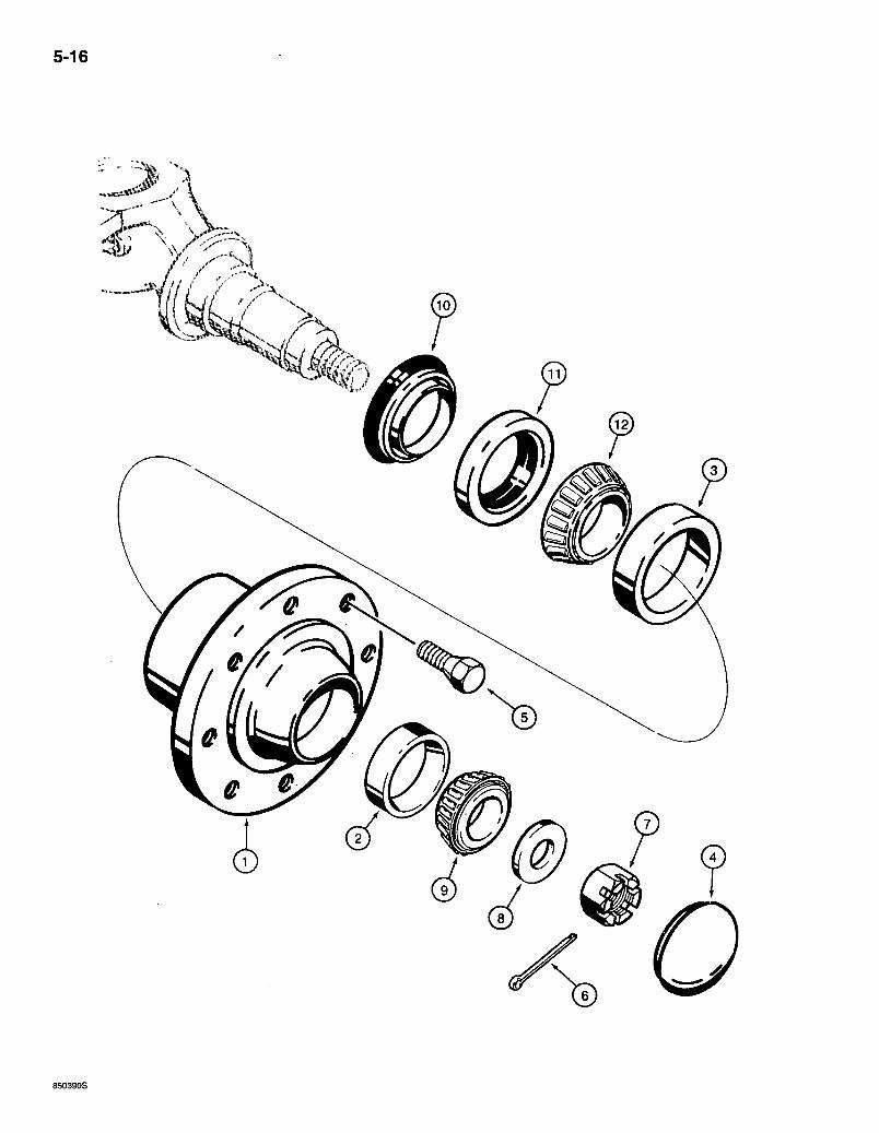
5-16
850390S
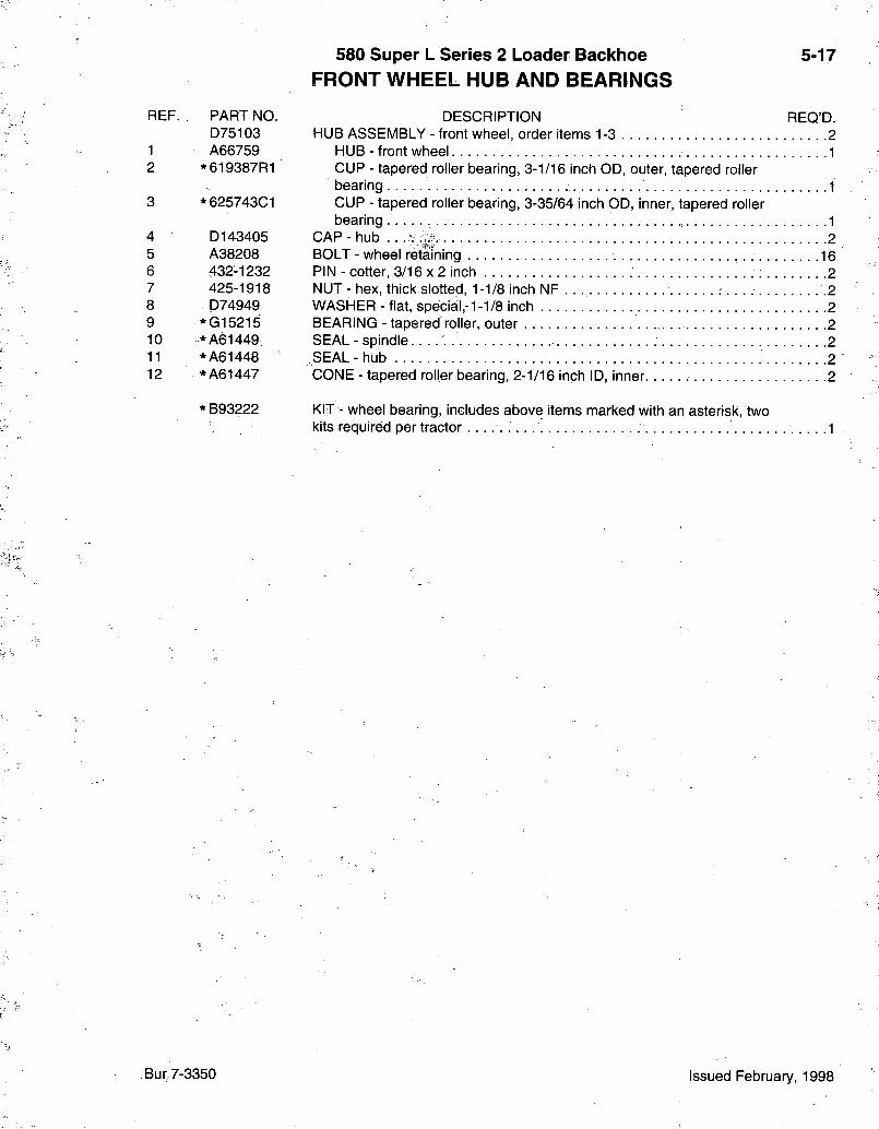
580 Super L Series 2 Loader Backlioe FRONT WHEEL HUB AND BEARINGS
5-17
REF. PART NO. D75103
1 A66759 2 *619387R1
3 *625743C1
4 D143405 5 A38208 6 432-1232 7 425-1918 8 D74949 9 *G15215 10 :*A61449 11 *A61448 12 *A61447
* B93222
DESCRIPTION REQ'D. HUB ASSEMBLY - front wheel, order items 1-3 2
HUB-front wheel 1 CUP - tapered roller bearing, 3-1/16 inch OD, outer, tapered roller bearing 1 CUP - tapered roller bearing, 3-35/64 inch OD, inner, tapered roller bearing 1
CAP-hub . . 2 BOLT - wheel retaining 16 PIN - cotter, 3/16x2 inch 2 NUT - hex, thick slotted, 1-1/8 inch NF . . .2 WASHER - flat, special,-1-1/8 inch 2 BEARING - tapered roller, outer 2 SEAL-spindle 2 SEAL-hub 2 CONE - tapered roller bearing, 2-1/16 inch ID, inner 2
KIT - wheel bearing, includes above items marked with an asterisk, two kits required per tractor 1
Bur 7-3350 Issued February, 1998
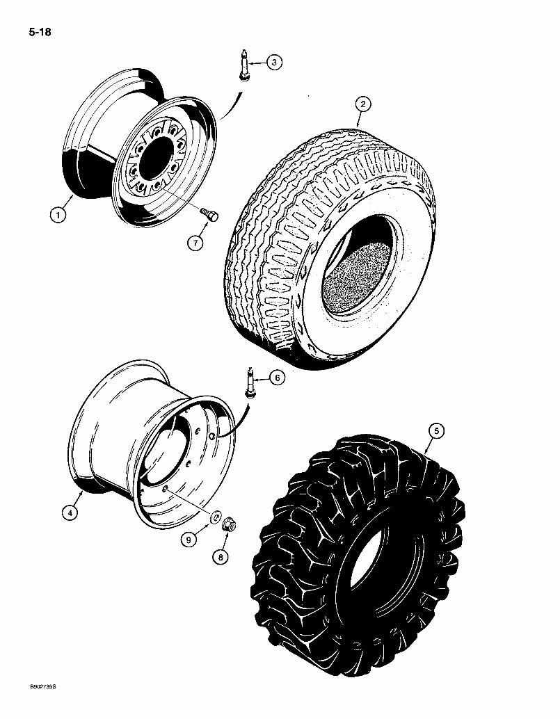
5-18
if
B902735S
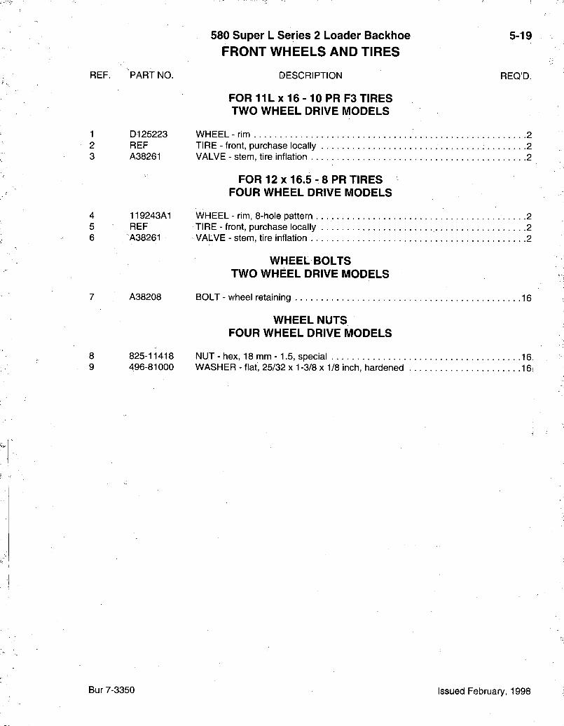
580 Super L Series 2 Loader Backhoe FRONT WHEELS AND TIRES
5-19
REF. PART NO. DESCRIPTION
FOR 11L X 16 -10 PR F3 TIRES TWO WHEEL DRIVE MODELS
REQ'D.
1 D125223 WHEEL-rim 2 2 REF TIRE - front, purchase locally 2 3 A38261 VALVE - stem, tire inflation 2
FOR 12x16.5- 8 PR TIRES FOUR WHEEL DRIVE MODELS
4 119243A1 WHEEL-rim, 8-hole pattern . . 2 5 REF TIRE - front, purchase locally 2 6 A38261 VALVE - stem, tire inflation . 2
WHEELBOLTS TWO WHEEL DRIVE MODELS
7 A38208 BOLT - wheel retaining 16
WHEEL NUTS FOUR WHEEL DRIVE MODELS
8 825-11418 NUT-hex, 18 mm - 1.5, special 16 9 496-81000 WASHER-flat, 25/32 X 1-3/8x 1/8 inch, hardened 16i
Bur 7-3350 Issued February, 1998
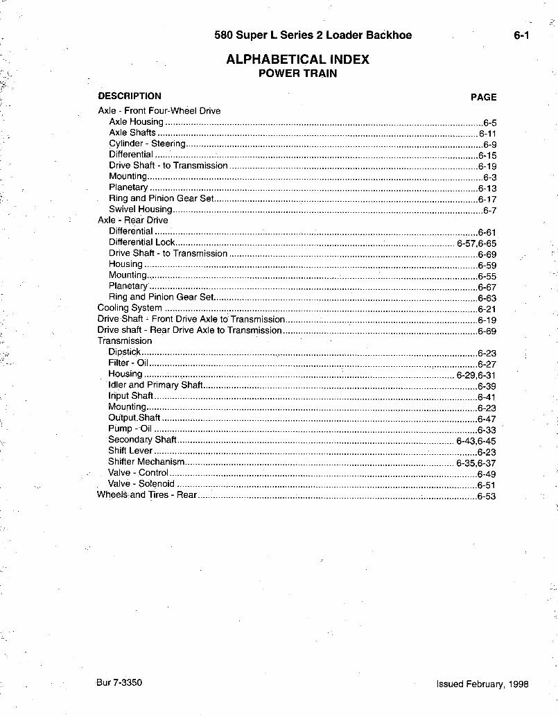
580 Super L Series 2 Loader Backhoe 6-1
ALPHABETICAL INDEX POWER TRAIN
DESCRIPTION PAGE Axle - Front Four-Wheel Drive
Axle Housing 6-5 Axle Shafts 6-11 Cylinder - Steering 6-9 Differential 6-15 Drive Shaft - to Transmission .6-19 Mounting 6-3 Planetary 6-13 Ring and Pinion Gear Set 6-17 Swivel Housing 6-7
Axle - Rear Drive Differential 6-61 Differential Lock 6-57,6-65 Drive Shaft - to Transmission 6-69 Housing .6-59 Mounting.. 6-55 Planetary 6-67 Ring and Pinion Gear Set 6-63
Cooling System ; .....6-21 Drive Shaft - Front Drive Axle to Transmission 6-19 Drive shaft - Rear Drive Axle to Transmission 6-69 Transrnission
Dipstick 6-23 Filter-Oil 6-27 Housing 6-29,6-31 Idler and Primary Shaft 6-39 input Shaft 6-41 Mounting , 6-23 OutputShaft 6-47 Pump - Oil 6-33 Secondary Shaft 6-43,6-45 Shift Lever 6-23 Shifter Mechanism 6-35,6-37 Valve - Control 6-49 Valve - Solenoid 6-51
Wheels and Tires - Rear 6-53
Bur 7-3350 Issued February, 1998

6-2
BT97M218
580 Super L Series 2 Loader Backhoe FRONT DRIVE AXLE MOUNTING AND DRIVE SHAFT
6-3
REF. PART NO. 1 113561A1 2 825-11418 3 496-81000 4 * 218-5351 4A 237-6006 5 * 218-5280 5A 237-6006 6 219-1 7 800-44050 8 191796A1 9 138616A1 10 D123684 11 284713A1 12 608-12025 13 137223A2 14 827-12045 15 495-21056 16 90-6682T1 17 D137627 18 282038A1 19 282033A1 20 495-21056 21 827-12045 22 829-1412
DESCRIPTION REQ'D. AXLE ASSEMBLY - front drive, parts list pages 6-5 - 6-17 1 NUT-hex, 18 mm-1.5 16 WASHER - flat, 25/32 x 1-3/8 x 1/8 inch, hardened : . .16 ADAPTER - straight, 3/4-16 flare x 9/16-18 inch 0-ring boss 1
0-RING - 15/32 ID x 5/64 inch wide 1 ELBOW - 90 degree, 3/4-16 flare x 9/16-18 inch adj 0-ring boss 1
0-RING.- 15/32 ID-x 5/64 inch wide 1 FITTING - grease, straight, 1/8 PT x 21/32 inch 2 RING - external retaining. No. 50, 50 mm 2 WASHER - flat, special, 2-1/32 ID x 4 OD x 1/16 inch thick UAR PIN - axle pivot 1 WASHER-thrust, 2-1/16x4-1/2x3/16 inch UAR SHAFT ASSEMBLY - drive, front drive axle, parts list page 6-19 1 BOLT - hex, self-locking, 12 - 1.75 x 25 mm, class 10.9.. 4 GUARD - drive shaft, used on models with 31 gallon fuel tank 1 BOLT-hex, 12 WASHER - flat.
- 1.75 X 45 mm, class 10.9. . . 4 9/16 X 1-3/8x7/64 inch 4
RETAINER - drive shaft, strap 2 BOLT - special.I 4 GUARD - drive shaft, used on models with 40 gallon fuel tank 1 BRACKET - guard 1 WASHER - flat, 9/16 X 1-3/8 x 7/64 inch 8 BOLT - hex, 12 - 1.75 x 45 mm, class 10.9 6 NUT - hex, 12 mm -1.75, class 10 2
* NOTE: See page 5-5 for fittings used on two wheel drive steering hydraulics.
Bur 7-3350 Issued February, 1998
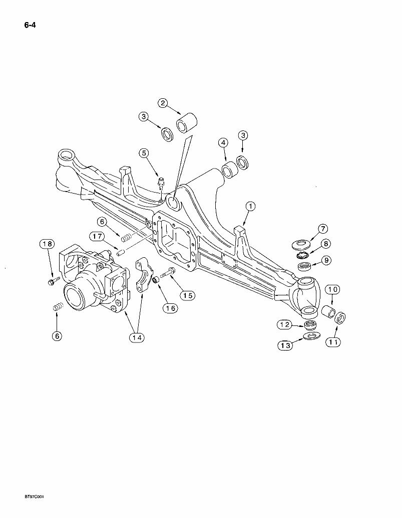
6-4
BT97C001
580 Super L Series 2 Loader Backhoe FRONT DRIVE AXLE
AXLE HOUSING
6-5
REF. PART NO. 113561A1
1 144453A1 2 D149725 3 N14367 4 D149726 5 1966149C1 6 A156873 7 122270A1 8 136990A1 9 100522A1 10 1966186C1 11 1966191G1 12 100520A1 13 122268A1
144454A1 14 NSS 15 .8301065 16 1966,13601 17 196613801 18 S301064
B17575
DESORIPTION REQ'p.-AXLE ASSEMBLY - front drive, Oarraro No. 131204, parts list pages 6-5 -6-17 1
HOUSING - front axle., 1 BUSHING - rear pivot -1 SEAL - bushing, front and rear. . . ; 2 BUSHING - front pivot 1 BREATHER - axle housing 1 PLUG - drain, 22 mm, housing and carrier :2 WASHER - Belleville, upper 2 WASHER - spacer, front axle 2 BUSHING - housing 2 BUSHING - housing 2 SEAL - oil 2 BUSHING - spherical, housing, lower 2 WASHER - Belleville, lower 2 OARRIER ASSEMBLY - differential 1
CARRIER - differentail 1 BOLT - hex, special, 14 mm x 75 mm .4 BUSHING - centering, carrier. 4
PIN - dowel, housing to carrier. 2 BOLT - hex flange, 12 x 33 mm, class 12.9, carrier to housing 10
SEALANT - black RTV silicone, 89 ml (3 ounce) tube, differential carrier to axle housing, not shown UAR
NOTE: See page 6-3 for axle mounting.
Bur 7-3350 Issued February, 1998
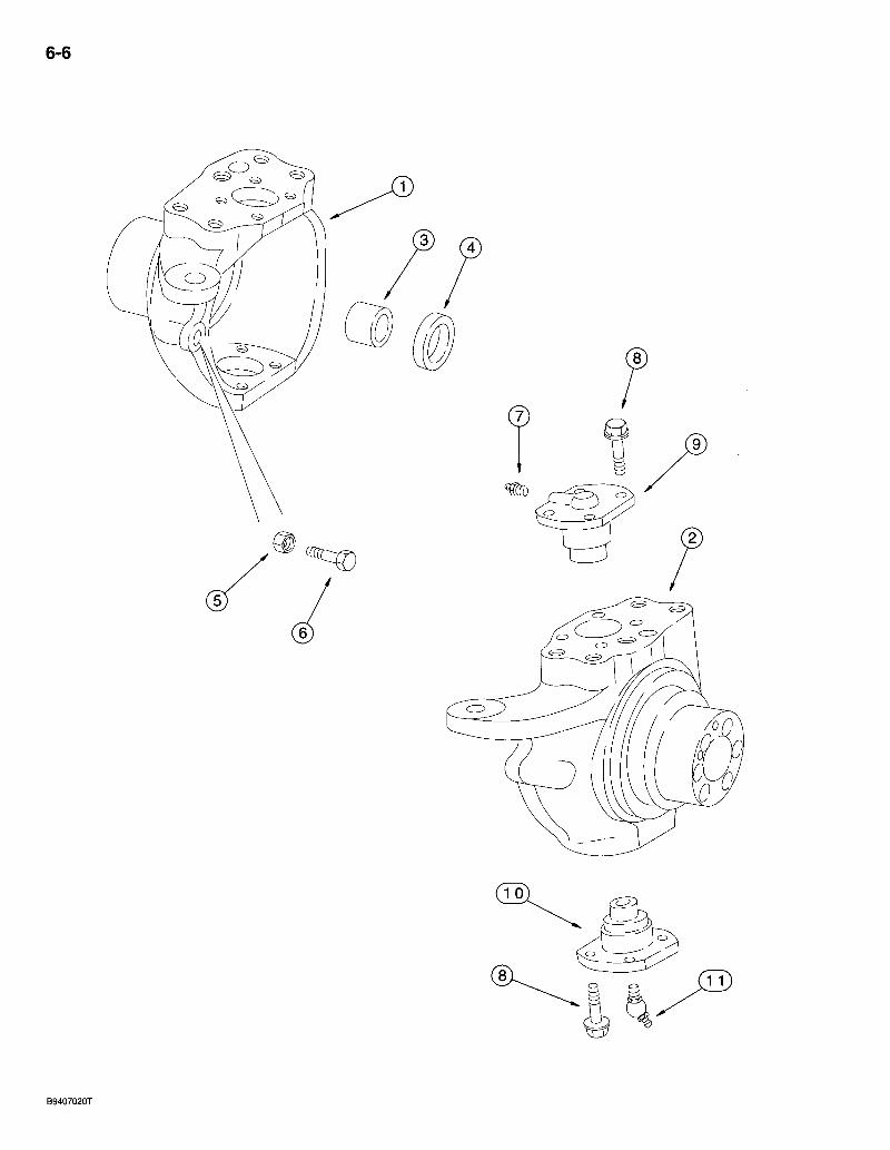
6-6
B9407020T

580 Super L Series 2 Loader Backhoe FRONT DRIVE A X L E
SWIVEL HOUSING
6-7
REF. PART NO. 113561A1
1 144455A1 2 144456A1 3 100532A1
4 100529A1 5 1537663C1 6 1537664C1 7 712998R91 8 100533A1 9 122265A1 10 122264A1 11 N13505
B17575.
DESCRIPTION REQ'D: AXLE ASSEMBLY - front drive, Carraro No. 131204, parts list pages 6-5 -6-17 1
HOUSING - swivel, left-hand, includes item 3, 100532A1 bushing 1 HOUSING - swivel, right-hand 1
BUSHING - swivel housing, used with right-hand orileft-hand. swivel housing .1
SEAL - oil, swivel housing 2 NUT - hex, special, 16 mm 2 BOLT - special; steering stop, 16 mm 2 FITTING - grease, straight, swivel cap 2 BOLT - hex, special 16 PIN - king, swivel housing cap, upper 2 PIN - king, swivel housing cap, lower 2 FITTING - grease, 45 degree, special, swivel cap .2
SEALANT - black RTV silicone, 89 ml (3 ounce) tube, wear ring to swivel housing, not shown UAR
Bur 7-3350 Issued February, 1998
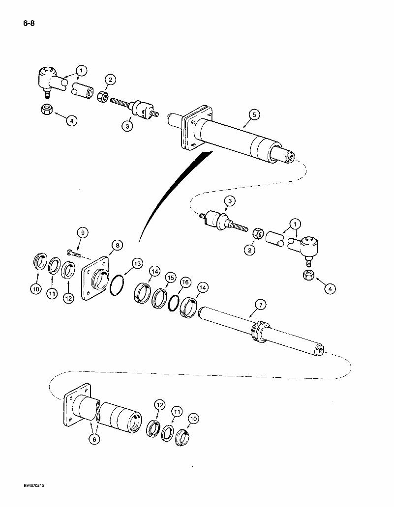
6-8
580 Super L Series 2 Loader Bacl<hoe FRONT DRIVE AXLE STEERING CYLINDER
6-9
REF.
1 2 3 4 5
6 7 8 9
10 11 12 13 14 15 16
PART NO. 113561A1
144457A1 NSS 934727R1 112509A1 905839R1 144458A1
D149738 144459A1 D149737 114296A1
*NSS *NSS *NSS *NSS *NSS *NSS *NSS
* D149739
B17575
DESCRIPTION REQ'D. AXLE ASSEMBLY - front drive, Carraro No. 131204, parts list pages 6-5 -6-17 1
ARM ASSEMBLY - steering 2 JOINT - ball, swivel side 1 NUT - hex, special 1 JOINT - ball, right-hand threads 1
NUT - hex, self-locking, 18 x 1.5 mm 2 CYLINDER ASSEMBLY - steering, order. D149739 kit to service seals, see below 1
TUBE - cylinder 1 ROD - piston 1 GLAND - cylinder 1 BOLT - self-locking, special, steering cylinder, for service order 100524A1 bolt and 892-11012 washer 4 W I P E R - r o d . . . . . . . . ; 2 RING - backup 2 SEAL- rod -2 0-RING - gland 1 RING- wear . 2 SEAL - piston 1 0-RING - expander 1
KIT - seal, steering cylinder, for rod, gland, and piston, includes all items with an asterisk 1
SEALANT - black RTV silicone, 89 ml (3 ounce) tube, cylinder flange to cylinder, not shown . UAR
Bur 7-3350 Issued February, 1998
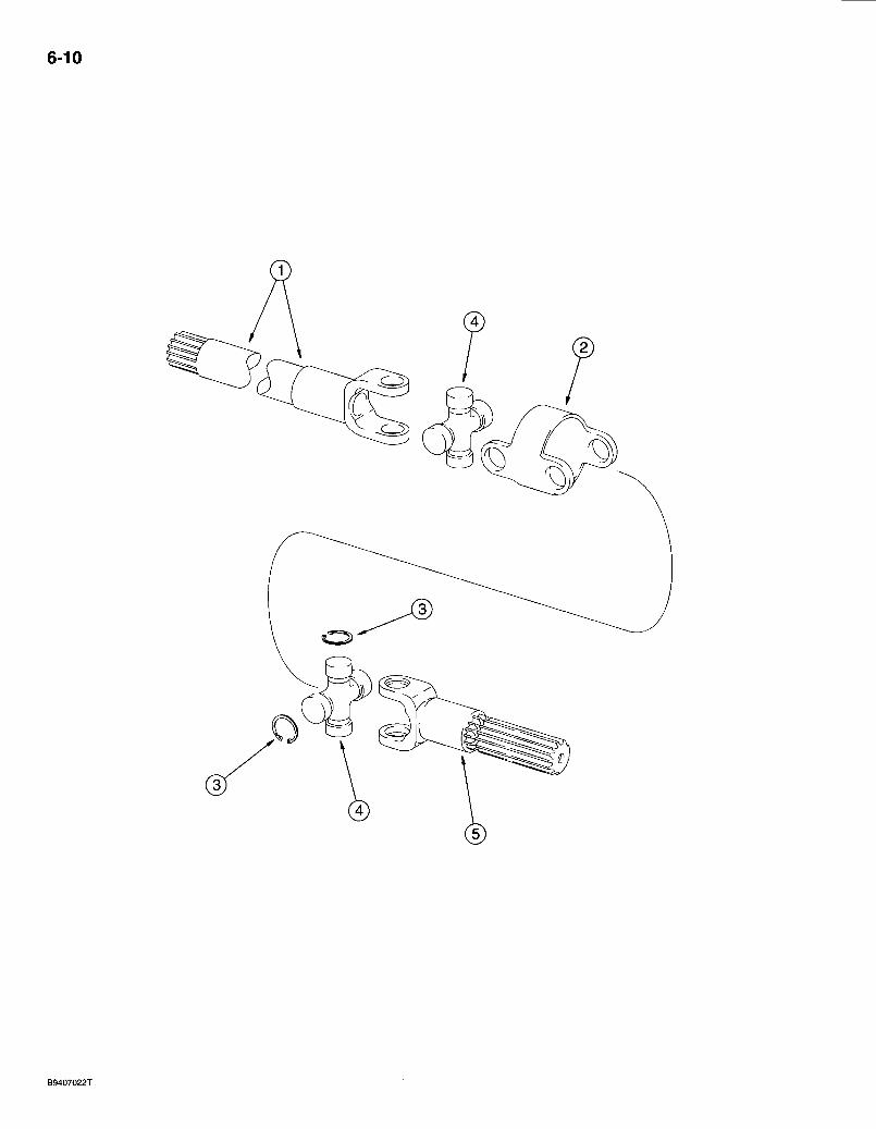
6-10

580 Super L Series 2 Loader Backhoe FRONT DRIVE AXLE
AXLE SHAFTS
6-11
REF.
1 2 3 4 5
PART NO. DESCRIPTION REQ'D. 113561A1 AXLE ASSEMBLY - front drive, Carraro No. 131204, parts list pages 6-5
- 6-17, see page 6-3 for mounting 1 144461A1 SHAFT ASSEMBLY - axle, front and rear, order items 1-5 2 144462A1 SHAFT - axle, differential side, long 2 144464A1 . BODY - connecting • • • -2 N14410 RING - snap, universal joint 16 144465A1 JOINT - universal, axle shaft, cross 4 144463A1 SHAFT - axle, wheel side, short 2
Bur 7-3350 Issued February, 1998

6-12
BS97M234
580 Super L Series 2 Loader Bacldioe FRONT DRIVE AXLE
PLANETARY
6-13
REF. PART NO. 113561A1
1 1984938C1 2 1966169C1
144466A1 3 NSS 4 i00556A1 5 100552A1 6 100559A1 7 116426A1 8 116427A1 9 190684A1 10 190682A1 11 A48041 12 116425A1 13 100561A1
100554A1 100553A1
14 NSS 15 . ^ NSS 16 K395093 17 800-1134 18 . 100555A1 19 100562A1 = 20 114295A1 21 K395091 22 100557A1 22A 238-6121 23 905876R1 24 ' 496-81000 25 825-11418
B17575
DESCRIPTION REQ'D. AXLE ASSEMBLY - front drive, Carraro No. 131204, parts list pages 6-5 -6-17. •<
SEAL-oil, hub 2 BEARING - tapered roller, hub. 2 HUB ASSEMBLY - front drive axle 2
HUB - wheel attaching 1 STUD - hub, special -8
0-RING-wheel hub 2 RING - backup, wheel hub O-ring 2
, BUSHING - carrier.. .12 . CARRIER - ring gear 2
WASHER - thrust. 2 WASHER- thrust 2 RING - snap 2 BOLT - hex, self-locking, special 12 GEAR - ring, planetary 2 PLANETARY ASSEMBLY - front drive axle. . 2
CARRIER ASSEMBLY - planetary 2 CARRIER - planetary 1 SHAFT - pinion gear 3 PIN-locking 1
RING - external retaining. No. 34 -6 RETAINER - pinion gear. • -2 GEAR - pinion, planetary 6 BEARING - needle, planetary gear, packet of 10 18 WASHER - thrust, pinion gear, outer 6 PLUG-drain 2
0-RING -1-1/16 ID X 3/32 inch wide 1 SCREW - special, planetary cover plate 4 WASHER - flat, 25/32 x 1-3/8 x 1/8 inch, hardened 16 NUT-hex, 18 mm-1.5 16
SEALANT - black RTV silicone, 89 ml (3 ounce) tube, planetary cover to hub, not shown UAR
Bur 7-3350 Issued February, 1998
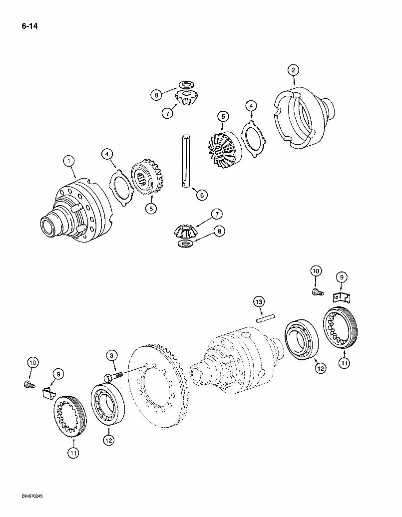
6-14
era
B9407024S
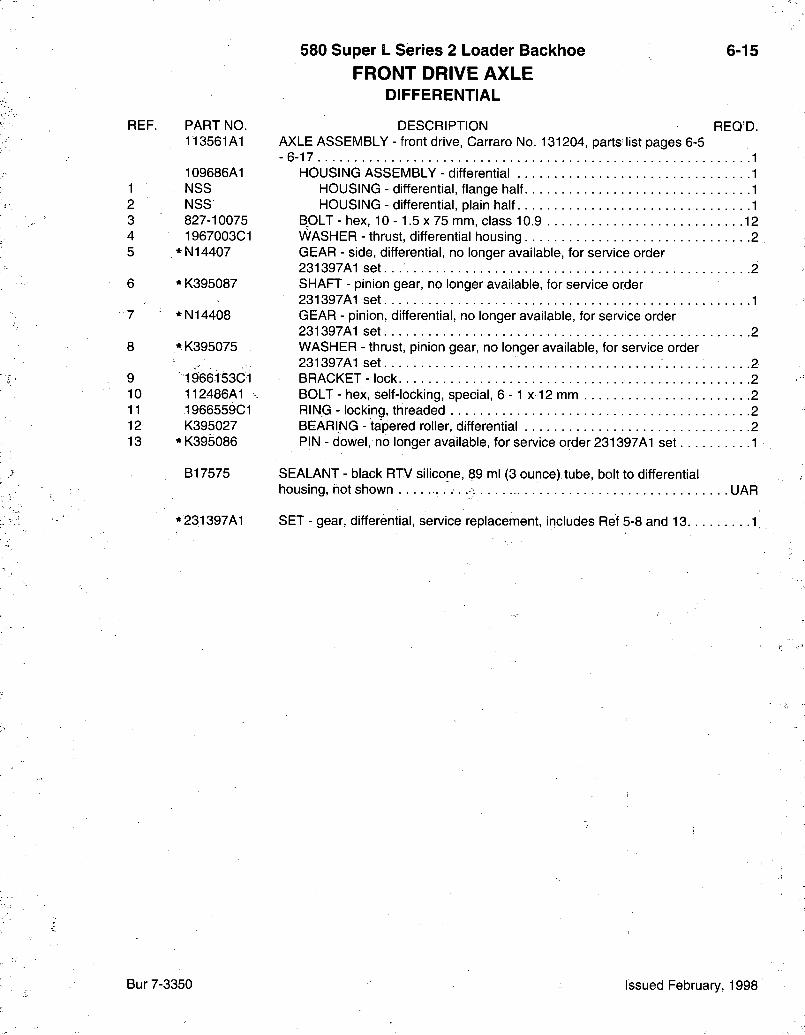
REF.
1 2 3 4 5
8
9 10 11 12 13
580 Super L Series 2 Loader Backhoe 6-15 FRONT DRIVE AXLE
DIFFERENTIAL
PART NO. DESCRIPTION REQ'D. 113561A1 AXLE ASSEMBLY - front drive, Carraro No. 131204, parts list pages 6-5
-6-17 1 109686A1 HOUSING ASSEMBLY - differential 1 NSS HOUSING - differential, flange half 1 NSS HOUSING - differential, plain half. 1 827-10075 BOLT - hex, 10 - 1.5 x 75 mm, class 10.9 12 1967003C1 WASHER - thrust, differential housing 2
* N14407 GEAR - side, differential, no longer available, for service order 231397A1 set. . 2
* K395087 SHAFT - pinion gear, no longer available, for service order 231397A1 set 1
* N14408 GEAR - pinion, differential, no longer available, for service order 231397A1 set 2
* K395075 WASHER - thrust, pinion gear, no longer available, for service order 231397A1 set 2
1966153C1 BRACKET - lock 2 112486A1 BOLT - hex, self-locking, special, 6 -1 x 12 mm 2 1966559C1 RING - locking, threaded .2 K395027 BEARING - tapered roller, differential 2
*K395086 PIN - dowel, no longer available, for service order 231397A1 set 1
B17575 SEALANT - black RTV silicone, 89 ml (3 ounce).tube, bolt to differential housing, not shown , . . . UAR
* 231397A1 SET - gear, differential, service replacement, includes Ref 5-8 and 13 1
Bur 7-3350 Issued February, 1998
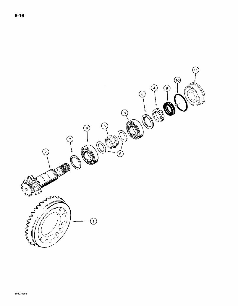
6-16
B9407025S

REF.
1 2 3 4 5 6 7 7 7 7 7 7 7 7 7 7 8 9 10 11
PART NO. 113561A1
144460A1 NSS NSS K261065 K261014 13.49058C1 1349059C1 140954A1 140953A1 140951A1 140949A1 140948A1 140943A1 140944A1 140945A1 140946A1 140947A1 K395090 K262143 238-5152 128570A1
580 Super L Series 2 Loader Backhoe FRONT DRIVE AXLE
RING AND PINION GEAR SET
AXLE ASSEMBLY -6-17
DESCRIPTION - front drive, Carraro No. 131204, parts list pages 6-5
6-17
REQ'D.
GEAR - set, ring and pinion GEAR - ring, differential GEAR - pinion, differential WASHER - special RING - nut, pinion gear SPACER - collapsible WASHER - spacer 2
SHIM - 2.5 mm (0.098 inch) thick UAR SHIM - 2.6 mm (0.102 inch) thick UAR SHIM - 2.7 mm (0.106 inch)thick -UAR SHIM - 2.8 mm (0.110 inch) thick. UAR SHIM - 2.9 mm (0.114 inch) thick UAR SHIM - 3.0 mm (0.118 inch) thick UAR SHIM - 3.1 mm (0.122 inch) thick UAR SHIM - 3.2 mm (0.125 inch) thick UAR SHIM - 3.3 mm (0.129 inch) thick. UAR SHIM - 3.4 mm (0.133 inch) thick UAR BEARING - tapered roller, pinion gear 2 SEAL -oil 1 0-RING - 3-1/4 ID X 3/32 inch wide 1 COVER - differential 1
B17575 SEALANT - black RTV silicone, 89 ml (3 ounce) tube, differential cover to differential carrier, not shown UAR
Bur 7-3350 Issued February, 1998
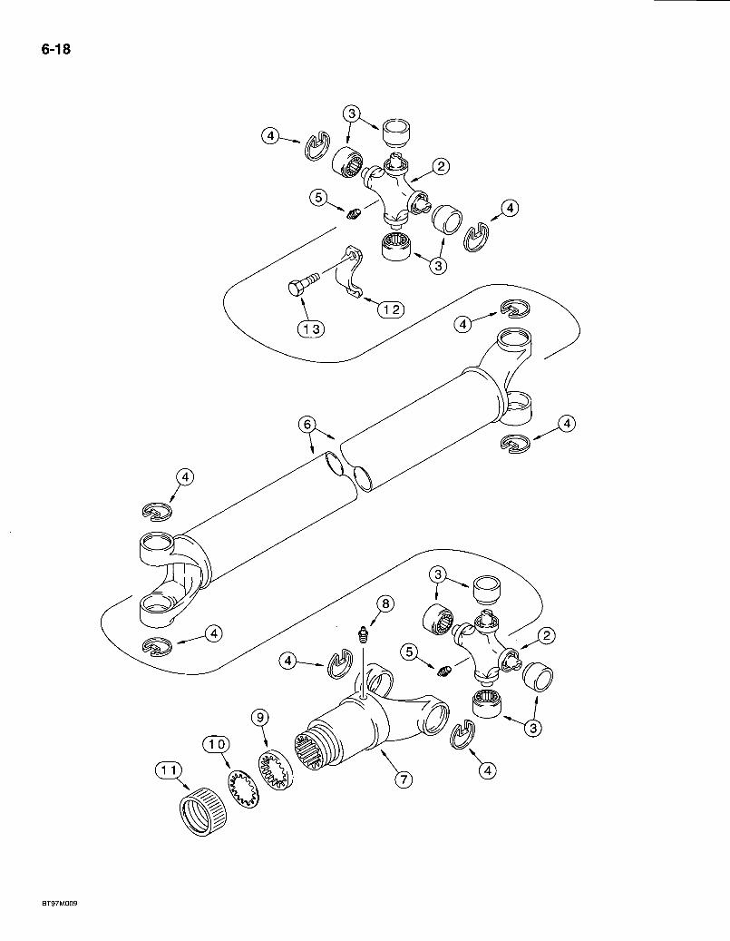
6-18
580 Super L Series 2 Loader Backhoe DRIVE SHAFT FOR FRONT DRIVE AXLE
FRONT DRIVE AXLE TO TRANSMISSION
6r19
REF. PART NO. 284713A1 144278A1
2 NSS 3 NSS 4 NSS 5 219-10 6 NSS 7 144279A1 8 219-10
D149860 9 NSS 10 NSS 11 NSS 12 90-6682T1
13 D137627
DESCRIPTION REQ'D. SHAFT ASSEMBLY - drive, fronf drive axle 1
KIT - universal joint .2 JOINT - universal, drive shaft 1 BEARING - universal joint 4 RING - retaining 4
FITTING - grease, straight, 1/4-28 taper x 11/16 inch 2 SHAFT - drive, transmission to rear axle YOKE - tube, spiined, to rear axle FITTING - grease, straight, 1/4-28 taper x 11/16 inch KIT - dust cap
WASHER - cork WASHERsteel CAP - dust seal retaining
RETAINER - drive shaft, strap, not included with the drive shaft assembly, purchase separately. 2 BOLT - special 4
Bur 7-3350 Issued February, 1998
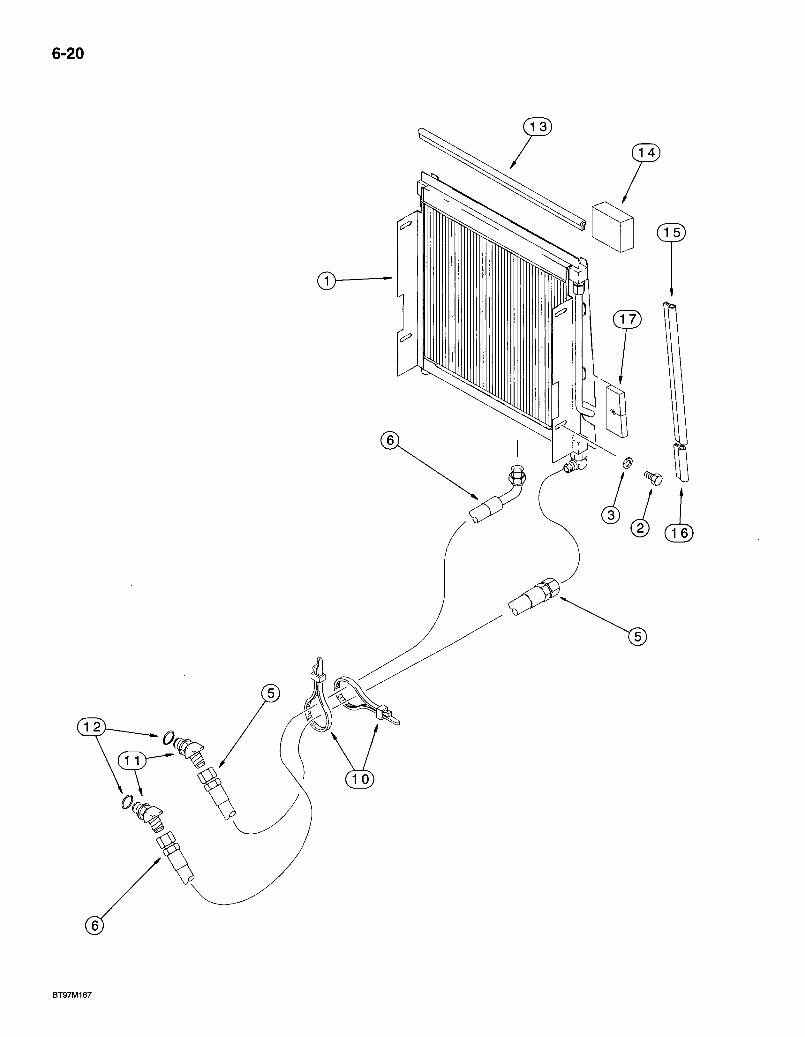
6-20
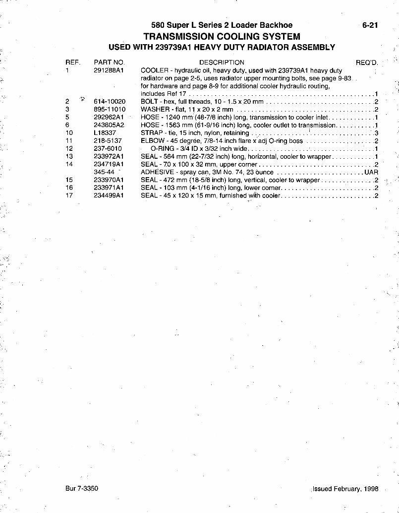
580 Super L Series 2 Loader Backhoe TRANSMISSION COOLING SYSTEM
USED WITH 239739A1 HEAVY DUTY RADIATOR ASSEMBLY
6-21
REF. 1
2 3 5 6 10 11 12 13 14
15 16 17
PART NO. 291288A1
614-10020 895-11010 292962A1 243805A2 LI 8337 218-5137 237-6010 233972A1 234719A1 345-44 • 233970A1 233971A1 234499A1
DESCRIPTION REQ'D. COOLER - hydraulic oil, heavy duty, used with 239739A1 heavy duty radiator on page 2-5, uses radiator upper mounting bolts, see page 9-83. for hardware and page 8-9 for additional cooler hydraulic routing, includes Ref 17 1 BOLT - hex, full threads, 10 -1.5 x 20 mm 2 WASHER-fiat, 11 x 2 0 x 2 mm 2 HOSE - 1240 mm (48-7/8 inch) long, transmission to cooler inlet .1 HOSE - 1563 mm (61-9/16 inch) long, cooler outlet to transmission 1 STRAP-tie, 15 inch, nylon, retaining . .3 ELBOW - 45 degree, 7/8-14 inch flare x adj 0-ring boss 2
O-RING - 3/4 ID X 3/32 inch wide . .1 SEAL - 564 mm (22-7/32 inch) long, horizontal, cooler to wrapper 1 SEAL - 70 X 100 X 32 mm, upper corner 2 ADHESIVE - spray can, 3M No. 74, 23 dunce UAR SEAL - 472 mm (18-5/8 inch) long, vertical, cooler to wrapper .2 SEAL -103 mm (4-1/16 inch) long, lower corner. ' 2 SEAL - 45 X 120 X 15 mm, furnished with cooler 2
Bur 7-3350 Issued February, 1998

6-22

580 Super L Series 2 Loader Backhoe 6-23 TRANSMISSION MOUNTING, DRIVE SHAFT, DIPSTICK
AND GEAR SHIFT LEVER
DESCRIPTION REQ'D. KNOB - upper, cover 1 KNOB-lower 1 SCREW - set, hex socket headless, 5/16,NF x 3/8 inch, half dog point 1 SCREW - machine, pan head slotted, No. 10 NF x 7/8 inch 2 WASHER - external tooth lock, 3/16 inch 2 LEVER - transmission gear shift, see page 4-11 for clutch cutout harness and switch 1 BOOT - transmission gear shift lever 1 SCREW - self-tapping, hex washer head. No. 10 - 16 x 1 inch 4 BOLT - hex, 12 - 1.75 x 55 mm, class 10.9 1 WASHER-flat, 17/32x1-1/16x3/32 inch 1 NUT - hex, self-locking, 12 mm -1.75 1 KEY - Woodruff, 3/16 x 3/4 inch 1 SPRING - return, shift lever 1 TRANSMISSION ASSEMBLY - two wheel drive, parts list pages 6-27 -6-49 1 TRANSMISSION ASSEMBLY - four wheel drive, parts list pages 6-27 -6-51 1 BOLT - hex, full threads, 10 -1.5 x 35 mm, class 10.9 .12. WASHER - flat, 13/32 x 13/16 x 3/32 inch, hardened 12 DIPSTICK - oil level, transmission 1 CONVERTER - torque, new . . . . 1 RETURN NUMBER - torque converter core, use this part number to return torque converter for credit when using a remanufactured assembly 1 CONVERTER - torque, remanufactured. North America only, component parts not serviced separately .1 BOLT - hex, 5/16 NF x 5/8 inch, grade 8 6 WASHER - flat, hardened, special.. 6 PLATE - adapter, torque converter to engine flywheel 1 WASHER - flat, 13/32 x 13/16 x 3/32 inch, hardened 6 BOLT - hex, full threads, 10 -1.5 x 16 mm, class 10.9 . . . . : : .6 BOLT - hex, full threads, 12 - 1.75 x 40 mm 7 WASHER - flat, 13.5 x 28 x 4 mm, hardened 7 BRACKET - mounting, transmission, right-hand 1 BRACKET - mounting, transmission, left-hand 1 BOLT-hex, 16-2.0x110 mm 2 WASHER - flat, special, 5/8 inch, hardened .6 INSULATOR - engine mount, rear 2 NUT - hex, self-locking, 16 mm - 2.0 2
+ NOTE: Used on models without powershift transmissions.
* NOTE: See page 6-27 for remanufactured transmission part numbers.
Continued on next page
REF. PART NO. 1 +187714A1 2 +187715A1 3 + 484-6316 4 + 459-11014. 5 + 493-41020 6 +179689A1
7 • +190618A1 8 + 280-16516 9 + 828-12055 10 + 495-11053 11 + 832-10412 12 + 126-116 13 +143370A1 14 *123842A2
15 *123843A2
16 627-10035 17 496-21041 20 121658A1 21 1995137C1 21 1995137C1C
21 1995137C1R
22 428-510 23 A15672 . 24 A178706 25 496-21041 26 626-10016 27 614-12040 28 896-15012 29 - 284641A1 30 284723A1 31 814-16110 32 D35009 33 117846A1 34 83^-10416
Bur 7-3350 Issued February, 1998
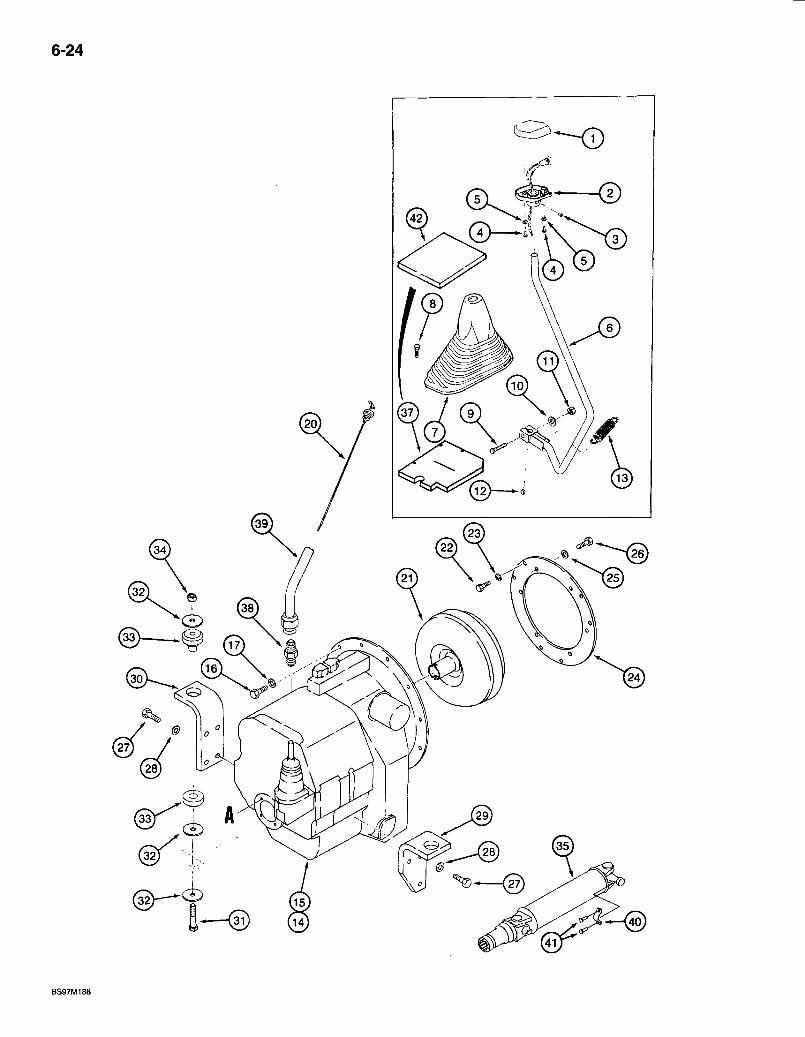
6-24
BS97M188
580 Super L Series 2 Loader Bacldioe 6-25 TRANSMISSION MOUNTING, DRIVE SHAFT, DIPSTICK
AND GEAR SHIFT LEVER
REF. PART NO. DESCRIPTION REQ'D. 35 284712A1 SHAFT ASSEMBLY - drive, transmission to rear axle, parts list page
6-69 1 37 2983,94A1 SEAL - foam, transmission control lever, installed between firewall and
flange on four speed shift lever boot, cab models only 1 38 218-459 ADAPTER - straight, 1-5/16-12 flare x 3/4 inch PT 1 39 237948A1 TUBE - transmission dipstick 1 40 90-6682T1 RETAINER - drive shaft, strap 2 41 D137627 BOLT - special 4 42 292514A1 SEAL - foam, noise reduction, cab models 1
Bur 7-3350 Issued February, 1998
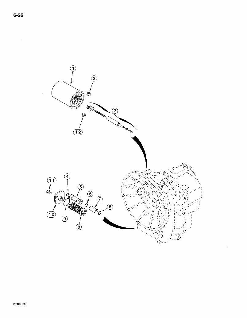
6-26
J ®
BT97M189
REF. PART NO. 123842A2
123842A2C
123842A2R
123843A2
123843A2C
123843A2R
1 254686A1 2 181101A1 3 181274A1 4 181141A1 5 ' 181196A1 6 190426A1
7 190433A1 8 278534A1 9 100748A1 10 181219A1 11 614-8018 12 181102A1
580 Super L Series 2 Loader Backhoe 6-27 TRANSMISSION ASSEMBLY
OIL FILTERS TWO WHEEL AND FOUR WHEEL DRIVE
DESCRIPTION REQ'D. TRANSMISSION ASSEMBLY - two wheel drive, new, parts list pages 6-27-6-49 1 RETURN NUMBER - transmission core, use this part number to return transmission for credit when using a remanufactured assembly 1 TRANSMISSION ASSEMBLY - remanufactured. North America only, component parts shown on this page do not apply to the remanufactured assembly 1
TRANSMISSION ASSEMBLY - four wheel drive, new, parts list pages 6-27-6-51 / . . . : . . 1 RETURN NUMBER - transmission core, use this part number to return transmission for credit when using a remanufactured assembly 1 TRANSMISSION ASSEMBLY - remanufactured. North America only, component parts shown on this page do not apply to the remanufactured assembly 1
FILTER - oil, cartridge, transmission, 152 mm (6 inch) long 1 PLUG - oil, 14-1.5 mm, used on four wheel drive models only 1 KIT - valve, used on four wheel drive models only 1 O-RING - small, used on four wheel drive models only 1 PLUG - bypass valve, used on four wheel drive models only . . . 1 O-RING - bypass valve, cylinder, one (1) used at each end of item 7, cylinder bypass valve, used on four wheel drive modelslonly 2 CYLINDER -..bypass valve, used on four wheel drive models only . . . . . . . . . 1 FILTER - oil . . . . . 1 O-RING - sealing 1 COVER - access, oil filter 1 BOLT - hex, full threads, 8 - .1.25 x 18 mrh . . . . . . . . 2 PLUG - oil, used on four wheel drive models only 1
Bur 7-3350 Issued February, 1998
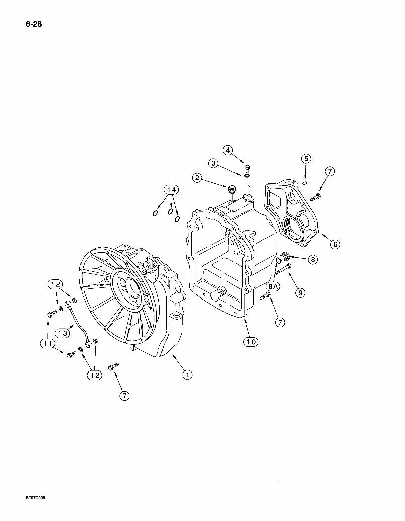
6-28
BT97C005
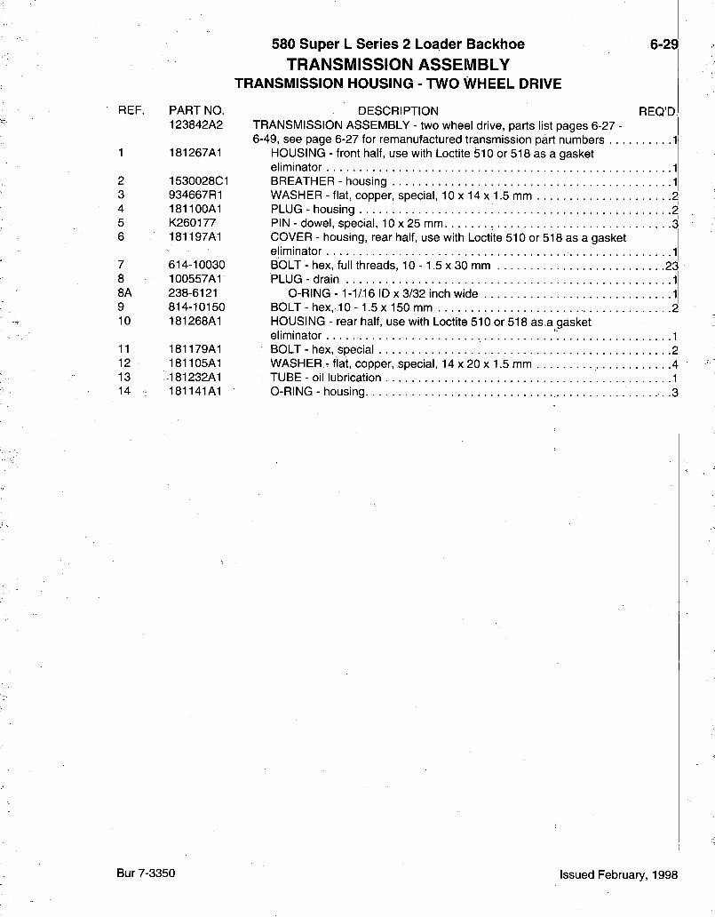
580 Super L Series 2 Loader Backhoe TRANSMISSION ASSEMBLY
TRANSMISSION HOUSING - TWO WHEEL DRIVE
REF. PART NO. 123842A2
1 181267A1
2 1530028C1 3 934667R1 4 181100A1 5 K260177 6 181197A1
7 614-10030 8 100557A1 8A 238-6121 9 814-10150 10 181268A1
11 181179A1 12 181105A1 13 •181232A1 14 : 181141A1
6-29
REQ'D.I DESCRIPTION TRANSMISSION ASSEMBLY - two wheel drive, parts list pages 6-27 -6-49, see page 6-27 for remanufactured transmission part numbers 1
HOUSING - front half, use with Loctite 510 or 518 as a gasket eliminator 1 BREATHER - housing 1 WASHER - flat, copper, special, 10 x 14 x 1.5 mm .2 PLUG - housing 2 PIN - dowel, special, 10 x 25 mm 3 COVER - housing, rear half, use with Loctite 510 or 518 as a gasket eliminator 1 BOLT - hex, full threads, 10 -1.5 x 30 mm 2$ PLUG-drain 1
O-RING -1-1/16 ID x 3/32 inch wide 1 BOLT - hex, 10 -1.5 x 150 mm 2 HOUSING - rear half, use with Loctite 510 or 518 as.a gasket eliminator 1 BOLT - hex, special . 2 WASHER - flat, copper, special, 14 x 20 x 1.5 mm 4 TUBE - oil lubrication 1 O-RING - housing .3
Bur 7-3350 Issued February, 1998
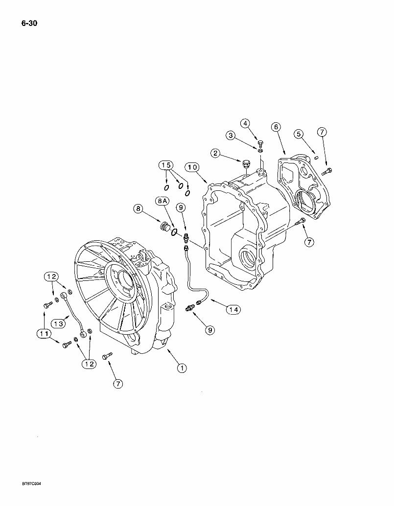
6-30
0 o\ <
BT97C004
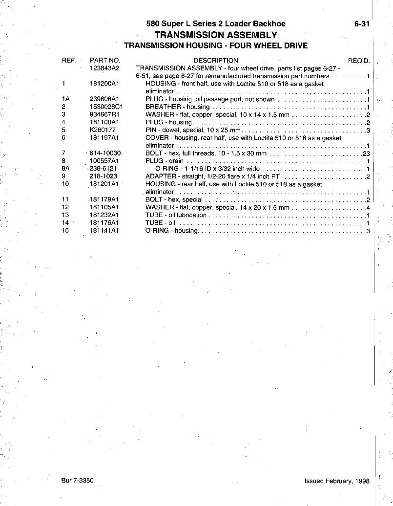
580 Super L Series 2 Loader Backhoe TRANSMISSION ASSEMBLY
TRANSIVIISSION HOUSING - FOUR WHEEL DRIVE
6-31
REF. PART NO. 123843A2
1 181200A1
1A 239606A1 2 1530028C1 3 934667R1 4 181100A1 5 K260177 6 181197A1
7 614-10030 8 100557A1 8A 238-6121 9 218-1023 10 181201A1
11 181179A1 12 181105A1 13 181232A1 14 181176A1 15 18'1141A1
DESCRIPTION REQ'D. TRANSMISSION ASSEMBLY - four wheel drive, parts list pages 6-27 -6-51, see page 6-27 for remanufactured transmission part numbers 1
HOUSING - front half, use with Loctite 510 or 518 as a gasket eliminator 1 PLUG - housing, oil passage port, not shown 1 BREATHER - housing 1 WASHER - flat, copper, special, 10 x 14 x 1.5 mm 2 PLUG - housing 2 -PIN - dowel, special, 10 x 25 mm 3 COVER - housing, rear half, use with Loctite 510 or 518 as a gasket eliminator 1 BOLT - hex, full threads, 10 -1.5 x 30 mm 23 PLUG-drain 1
O-RING - 1-1/16 ID X 3/32 inch wide 1 ADAPTER - straight, 1/2-20 flare x 1/4 inch PT 2 HOUSING - rear half, use with Loctite 510 or 518 as a gasket eliminator ^ 1 BOLT - hex, special 2 WASHER - flat, copper, special, 14 x 20 x 1.5 mm . . 4 TUBE - oil lubrication 1 TUBE-oil • -1 O-RING - housing. 3
Bur 7-3350 Issued February, 1998

6-32
BT95G027
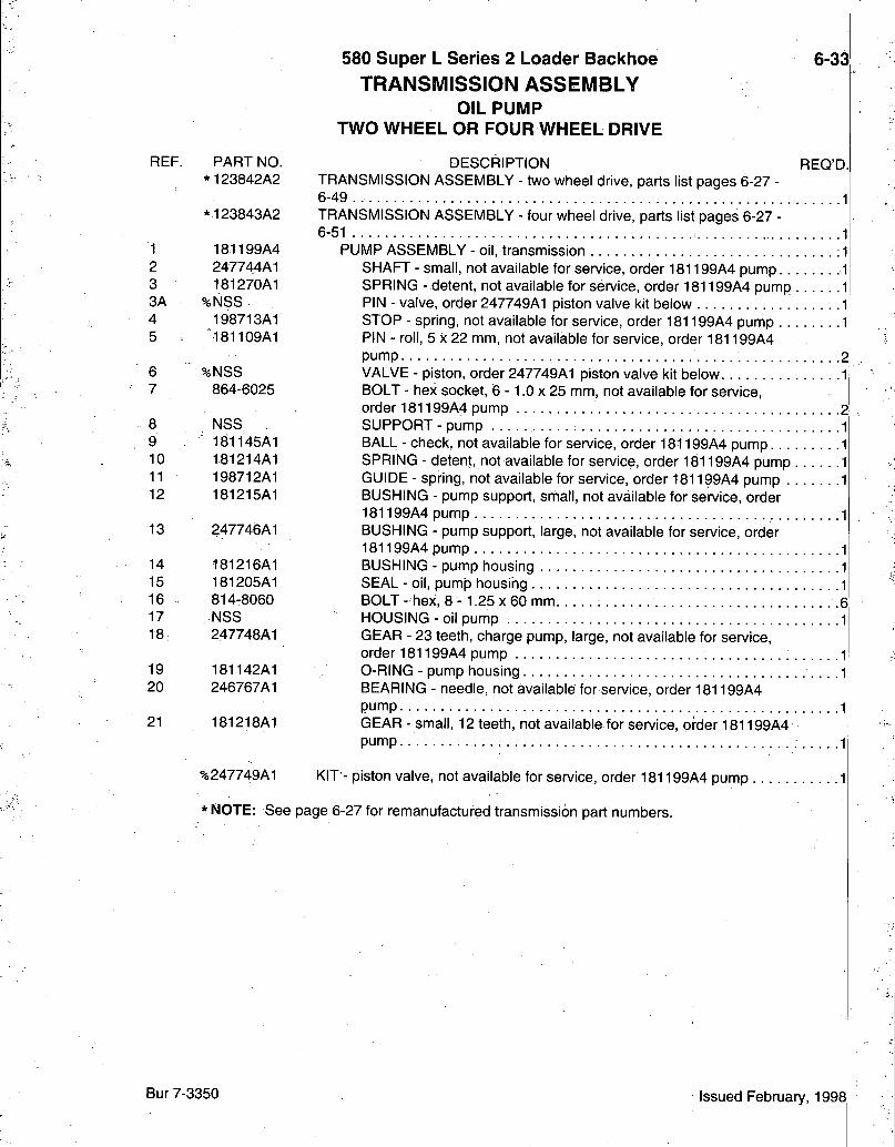
REF.
1 2 3 3A 4 5
6 7
8 9 10 11 12
13
14 15 16 17 18
19 20
21
PART NO. * 123842A2
*123843A2
181199A4 247744A1 181270A1
%NSS 198713A1 181109A1
%NSS 864-6025
NSS 181145A1 181214A1 198712A1 181215A1
247746A1
181216A1 181205A1 814-8060 NSS 247748A1
181142A1 246767A1
181218A1
580 Super L Series 2 Loader Backhoe 6-33 TRANSMISSION ASSEMBLY
OIL PUMP TWO WHEEL OR FOUR WHEEL DRIVE
DESCRIPTION REQ'D. TRANSMISSION ASSEMBLY - two wheel drive, parts list pages 6-27 -6-49 . 1
four wheel drive, parts list pages 6-27 TRANSMISSION ASSEMBLY 6-51 1
PUMP ASSEMBLY - oil, transmission .1 SHAFT - small, not available for service, order 181199A4 pump 1 SPRING - detent, not available for service, order 181199A4 pump 1 PIN - valve, order 247749A1 piston valve kit below 1 STOP - spring, not available for service, order 181199A4 pump 1 PIN - roll, 5 X 22 mm, not available for service, order 181199A4 pump 2 VALVE - piston, order 247749Al piston valve kit below 1 BOLT - hex socket, 6 -1 .0 x 25 mm, not available for service, order 181199A4 pump 2'
. .1
. .1
. .1
. .1
SUPPORT - pump BALL - check, not available for service, order 181199A4 pump. . . SPRING - detent, not available for service, order 181199A4 pump GUIDE - spring, not available for service, order 181199A4 pump . BUSHING - pump support, small, not available for service, order 181199A4 pump BUSHING - pump support, large, not available for service, order 181199A4 pump BUSHING - pump housing SEAL - oil, pumjD housing BOLT - hex, 8 - 1.25 x 60 mm 6 HOUSING - oil pump GEAR - 23 teeth, charge pump, large, not available for service, order 181199A4 pump O-RING - pump housing BEARING - needle, not available for service, order 181199A4 pump GEAR - small, 12 teeth, not available for service, order 181199A4 pump. •
%247749A1 KIT - piston valve, not available for service, order 181199A4 pump ,
* NOTE: See page 6-27 for remanufactured transmission part numbers.
Bur 7-3350 Issued February, 1998
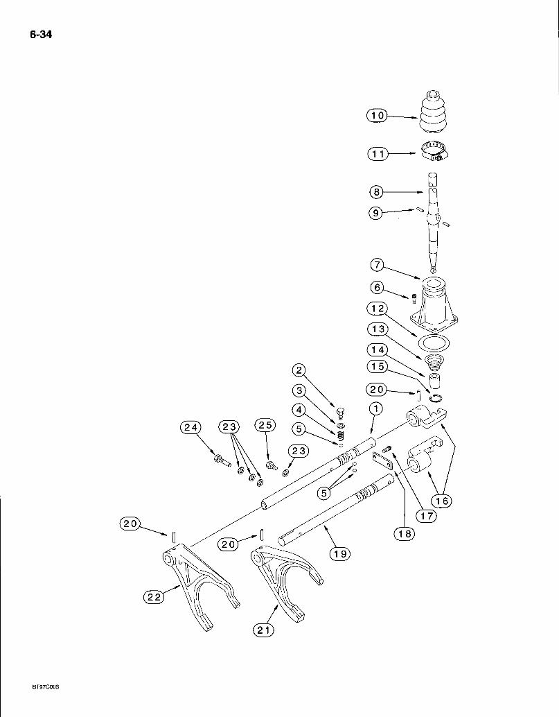
6-34
BT97C003

580 Super L Series 2 Loader Backhoe TRANSMISSION ASSEMBLY
TRANSMISSION SHIFTER MECHANISM TWO WHEEL OR FOUR WHEEL DRIVE
6 35
REF.
2 3 4 5 6 7 8
9
10
11 12 13
14
15
16 17 18 19 20
PART NO. *123842A2
*123843A2
%NSS
614-12016 1966835C1 1966993C1 181139A1 864-8025 181171A1
%NSS
%NSS
%NSS
181177A1 181138A1
%NSS
NSS
NSS
181173A1 864-10025 181175A1 181245A2
%905794R1
DESCRIPTION REQ'D. TRANSMISSION ASSEMBLY - two wheel drive, parts list pages 6-27 -6-49 1 TRANSMISSION ASSEMBLY - four wheel drive, parts list pages 6-27 -6-51 1
RAIL - shifter fork, third and fourth, no longer included in transmission assembly, order 256888A3 synchronizer kit, see below 1 BOLT - hex, full threads, 12 - 1.75 x 16 mm .3 WASHER - flat, special, 12 x 16 x 1.5 mm 3 SPRING - detent 2 BALL-detent 4 BOLT - hex socket, 8 - 1.25 x 25 mm 3 COVER - shift lever 1 LEVER - shift, replaces 190428A1, 190428A2 and 190428A3 lever, includes bushing and retaining ring, no longer included in transmission assembly, order 256888A3 kit .1 PIN - shift lever, replaces 1967585C1 pin, no longer included in transmission assembly, order 256888A3 synchronizer kit, see below 2 BOOT - rubber, replaces 1967581 C I boot, no longer included in transmission assembly, order 256888A3 synchronizer kit, see.below 1 CLAMP - adjustable 1 O-RING - sealing 1 SPRING - shift lever, replaces 1967586C1 and 190436A1 spring, no longer included in transmission assembly, order 256888A3 kit 1 BUSHING - shift lever, replaces 181180A1 bushing, no longer included in transmission assembly, bushing is now part of 190428A3 lever, Ref 8, which is not serviced separately, order 256888A3 kit 1 RING - external retaining, replaces 800-1115 ring, no longer included in transmission assembly, ring is now part of 190428A3 lever, Ref 8, which is not serviced separately, order 256888A3 kit 1 SHIFTER-rai l 2 BOLT - hex socket, 10 -1 .5 x 25 mm 2 PLATE - retainer, detent ball 1 RAIL - shifter fork, first and second 1 PIN - roll, 6 x 30 mm 2-4
%256888A3 KIT - synchronizer service, replaces 256888A2 kit, includes parts on pages 6-35, 6-37, 6T41 and 6-43, also includes (1 each) 278531A1 washer, 278532A1 bushing, 278533A1 spring and 279039A1 shift lever snap ring which are not sen/iced separately and not shown
* N O T E : See page 6-27 for remanufactured transmission part numbers.
Continued on next page
Bur 7-3350 Issued February, 1998
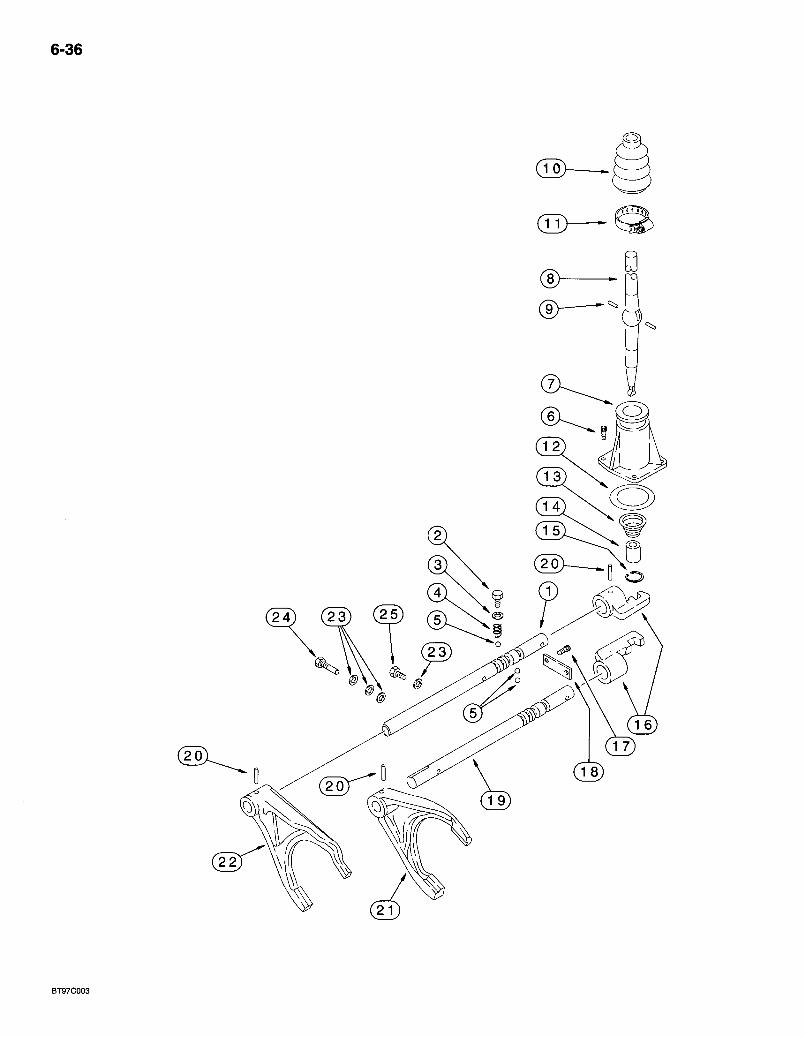
6-36
BT97C003
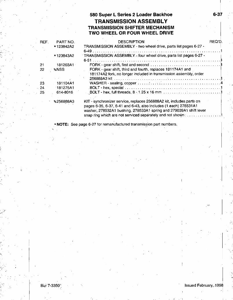
REF. PART NO. *123842A2
580 Super L Series 2 Loader Backhoe 6-37 TRANSMISSION ASSEMBLY
TRANSMISSION SHIFTER MECHANISM TWO WHEEL OR FOUR WHEEL DRIVE
DESCRIPTION REQ'D. TRANSMISSION ASSEMBLY - two wheel drive, parts list pages 6-27 -6-49
* 123843A2 TRANSMISSION ASSEMBLY . four wheel drive, parts list pages 6-27 6-51
21 22
23 24 25
181203A1 iNSS
181104A1 181275A1 614-8016
%256888A3
FORK - gear shift, first and second FORK - gear shift, third and fourth, replaces 181174A1 and 181174A2 fork, no longer included in transmission assembly, order 256888A3kit WASHER - sealing, copper BOLT - hex, special BOLT - hex, full threads, 8 -1.25 x 16 mm . . . . . . . . . . . ;l
KIT - synchronizer service, replaces 256888A2 kit, includes parts on pages 6-35, 6-37, 6-41 and 6-43, also includes (1 each) 278531A1 washer, 278532A1 bushing, 278533A1 spring and 279039A1 shift lever snap ring which are not serviced separately and not shown
• N O T E : See page 6-27 for remanufactured transmission part numbers.
Bur 7-3350:" Issued February,. 1998
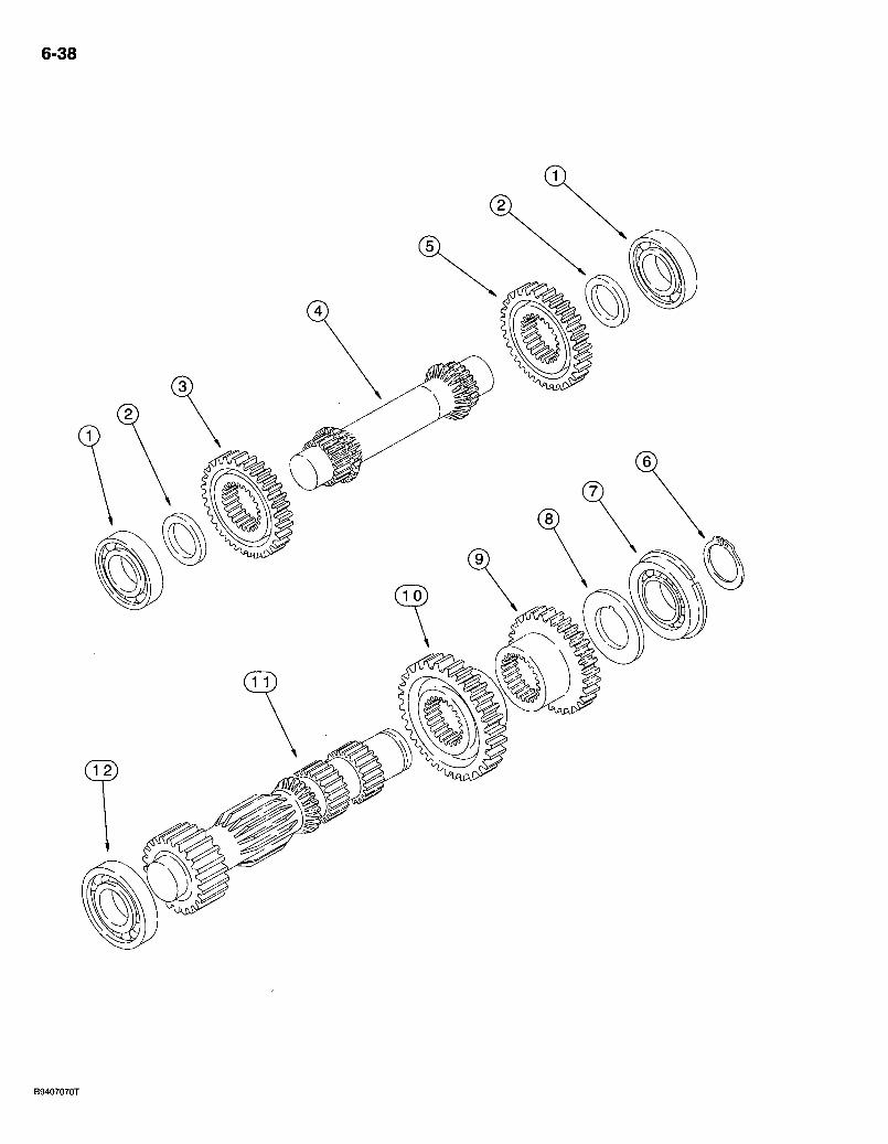
6-38
B9407070T
580 Super L Series 2 Loader Backhoe TRANSMISSION ASSEMBLY
IDLER AND PRIMARY SHAFT TWO WHEEL OR FOUR WHEEL DRIVE
6-39
REF. PART NO. *123842A2
*123843A2
1 . ST205A 2 181151A1 3 181186A1 4 181181A1 5 181186A1 6 A48041 7 181128A1 8 181154A1 9 181188A1 10 181187A1 11 181184A1 12 181132A1
REQ'Dl DESCRIPTION TRANSMISSION ASSEMBLY - two wheel drive, parts list;pages 6-27 6-49 TRANSMISSION ASSEMBLY - four wheel drive, parts list pages 6-27 -6-51 . . 1
BEARING-bal l 2 SHIM - bearing, 52 x 35.1 x 4 mm 2 GEAR - idler, 27 teeth 1 SHAFT - idler 1 GEAR - idler, 27 teeth 1 R ING-snap 1 BEARING-bal l 1 WASHER - thrust, 65 x 45 mm. 1 GEAR - drive, third, 28 teeth 1 GEAR - drive, fourth, 39 teeth 1 SHAFT - primary .1 BEARING - roller 1
* NOTE: See page 6-27 for remanufactured transmission part numbers.
Bur 7-3350 Issued February, 1998
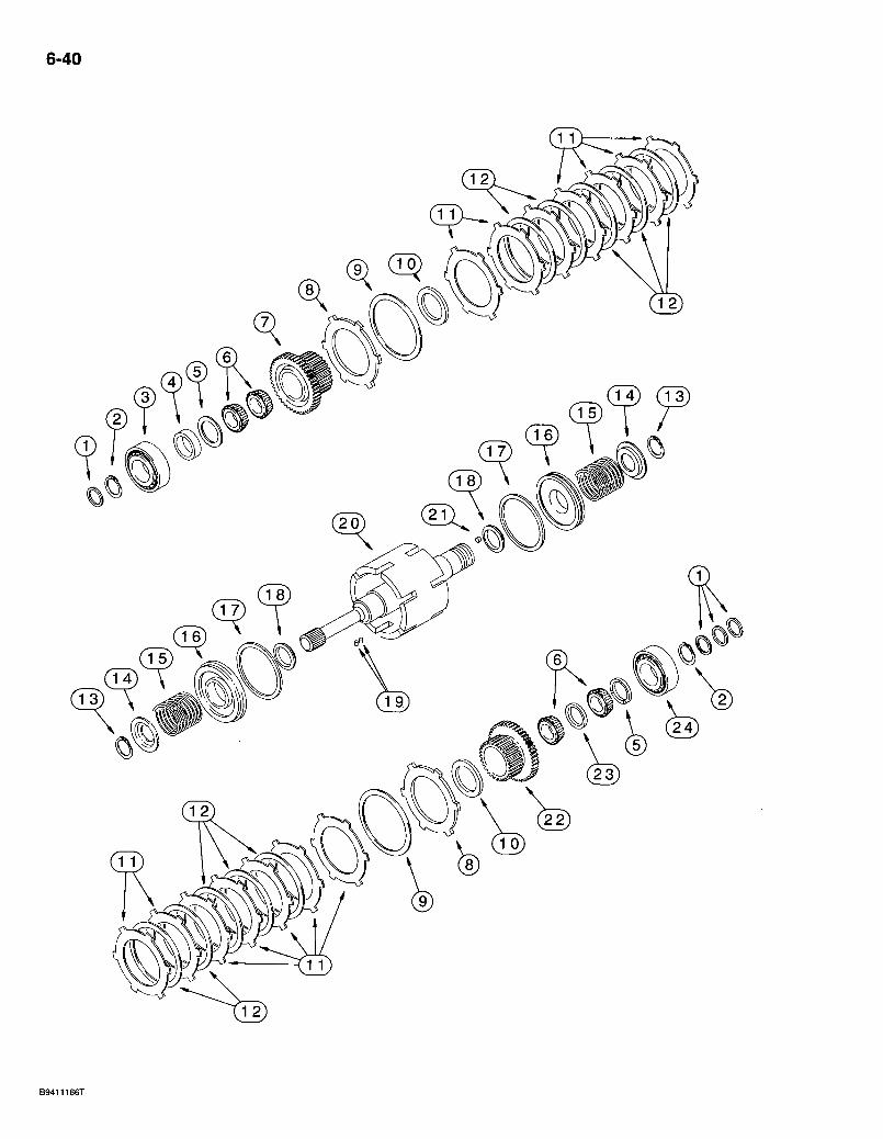
6-40

REF.
1 2 3 4 5 6 7 8 9 10 11 12 13 14 15
16
17 18 19 20 21 22 23 24
PART. NO. *123842A2
*123843A2
181152A3 A48041 181128A1 181153A1 181154A1 181135A1 181228A2 181162A1 181.116A1 181163A1 181159A1 181158A1 181111A1 181161 A l
%NSS
%NSS
181157A3 181156A3 181108A1 298203A1 D142898 181227A2 181164A1 181126A1
S256888A3
580 Super L Series 2 Loader Backlioe 6-41 TRANSMISSION ASSEMBLY
INPUT SHAFT TWO WHEEL OR FOUR WHEEL DRIVE
DESCRIPTION REO'D. TRANSMISSION-ASSEMBLY - two whedl drive, parts list pages 6-27 -6-49 |1 TRANSMISSION ASSEMBLY - four wheel drive, parts list pages 6-27 -6-51 •
SEAL-o i l RING - snap BEARING-bal l SPACER - bearing
= WASHER - thrust, 65 x 45 mm BEARING - needle GEAR - input shaft, 35 teeth PLATE - thrust R ING- lock WASHER- thrust PLATE - disc, intermediate. .1 PLATE-disc, clutch 1 RING-snap . PLATE - pressure SPRING - detent;Teplaces 181160A1 and 181160A2:spring, no longer included in transmission assembly, order 256888A3 synchronizer kit, see below ' PISTON - input shaft, replaces 181155A1 and 181155A2 piston, no longer included in transmission assembly, order 256888A3 synchronizer kit, see below RING-sea l ; RING - seal, small PIN - roll SHAFT- input PLUG- inputshaf t GEAR-shaf t , 29 teeth. SPACER - bearing BEARING- ball
KIT - synchronizer service, replaces 256888A2 kit, includes parts on pages 6-35, 6-37, 6-41 and 6-43, also includes.(1 each) 278531 A l washer, 278532A1 bushing, 278533A1 spring and 279039A1 shift lever snap ring which are not serviced separately and not shown
* NOTE: See page 6-27 for remanufactured transmission part numbers.
Bur7-3350 Issued February, 1998.
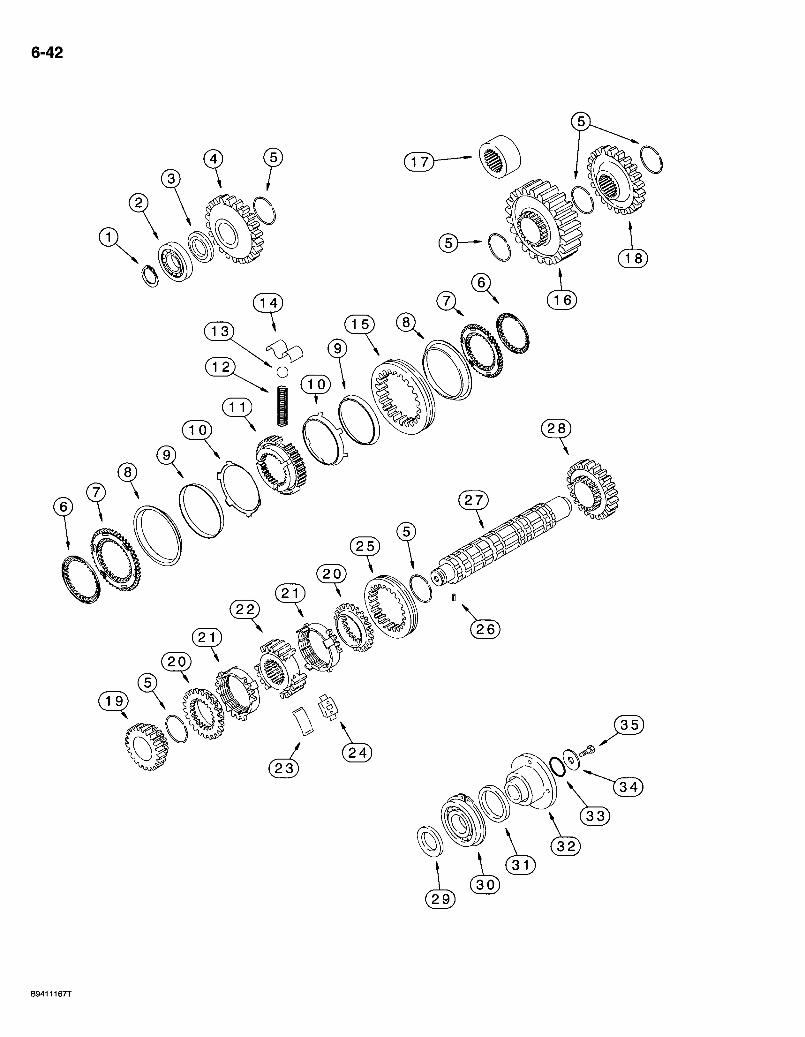
6-42
0
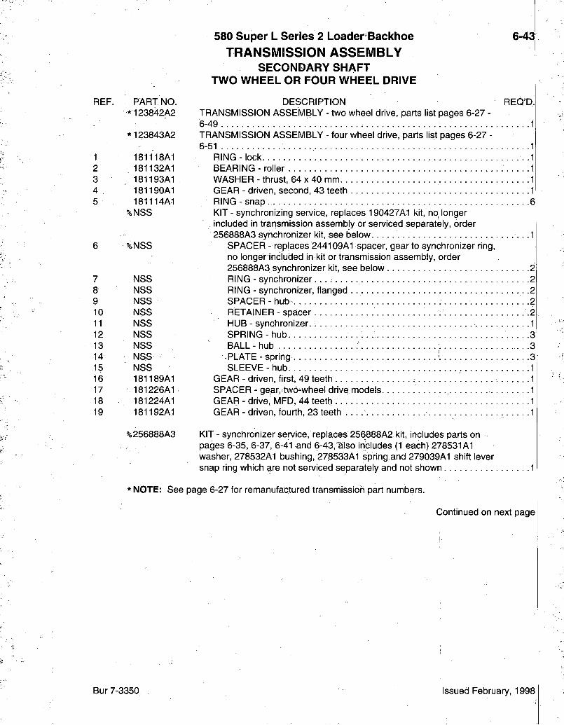
R E F .
1 2 3 4 5
7 8 9 1 0 1 1 1 2 1 3 1 4
. 1 5 1 6 1 7 1 8 1 9
P A R T N O . * 1 2 3 8 4 2 A 2
* 1 2 3 8 4 3 A 2
1 8 1 1 1 8 A 1 1 8 1 1 3 2 A 1 1 8 1 1 9 3 A 1 1 8 1 1 9 0 A 1 1 8 1 1 1 4 A 1
% N S S
% N S S
N S S N S S N S S N S S N S S N S S N S S N S S N S S
1 8 1 1 8 9 A 1 1 8 1 2 2 6 A 1 1 8 1 2 2 4 A 1 1 8 1 1 9 2 A 1
% 2 5 6 8 8 8 A 3
580 Super L Series 2 Loader Backhoe 6-43; TRANSMISSION ASSEMBLY
SECONDARY SHAFT TWO WHEEL OR FOUR WHEEL DRIVE
D E S C R I P T I O N R E O ' D ; T R A N S M I S S I O N A S S E M B L Y - two wheel drive, parts list pages 6 - 2 7 -6 - 4 9 • • • 1 T R A N S M I S S I O N A S S E M B L Y - four wheel drive, parts list pages 6 - 2 7 -6 - 5 1
R I N G - l o c k B E A R I N G - roller W A S H E R - thrust, 6 4 x 4 0 mm G E A R - driven, second, 4 3 teeth R I N G - snap K I T - synchronizing service, replaces 1 9 0 4 2 7 A 1 kit, no longer included in transmission assembly or serviced separately, order 2 5 6 8 8 8 A 3 synchronizer kit, see be\o\N
S P A C E R - replaces 2 4 4 1 0 9 A 1 spacer, gear to synchronizer ring, no longer included in kit or transmission assembly, order 2 5 6 8 8 8 A 3 synchronizer kit, see below 2 R I N G - synchronizer . . . 2 R I N G - synchronizer, flanged 2 S P A C E R - h u b 2 R E T A I N E R - spacer 2 H U B - synchronizer. . . . 1 S P R I N G - h u b 3 B A L L - h u b 3
- P L A T E - spring 3 S L E E V E - h u b
G E A R - driven, first, 4 9 teeth S P A C E R - gear,=tw6^wheel drive models G E A R - drive, M F D , 4 4 teeth • G E A R - driven, fourth, 2 3 teeth . . .
K I T - synchronizer service, replaces 2 5 6 8 8 8 A 2 kit, includes parts on pages 6 - 3 5 , 6 - 3 7 , 6 - 4 1 and 6-43, 'a lso includes (1 each) 2 7 8 5 3 1 A 1 washer, 2 7 8 5 3 2 A 1 bushing, 2 7 8 5 3 3 A 1 spring and 2 7 9 0 3 9 A 1 shift lever snap ring which are not serviced separately and not shown
* NOTE: See page 6 - 2 7 for remanufactured transmission part numbers.
Continued on next page
Bur 7 - 3 3 5 0 Issued February, 1 9 9 8
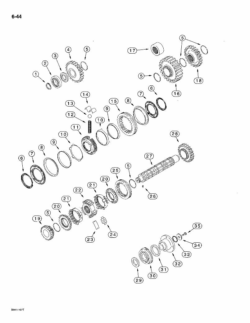
6-44
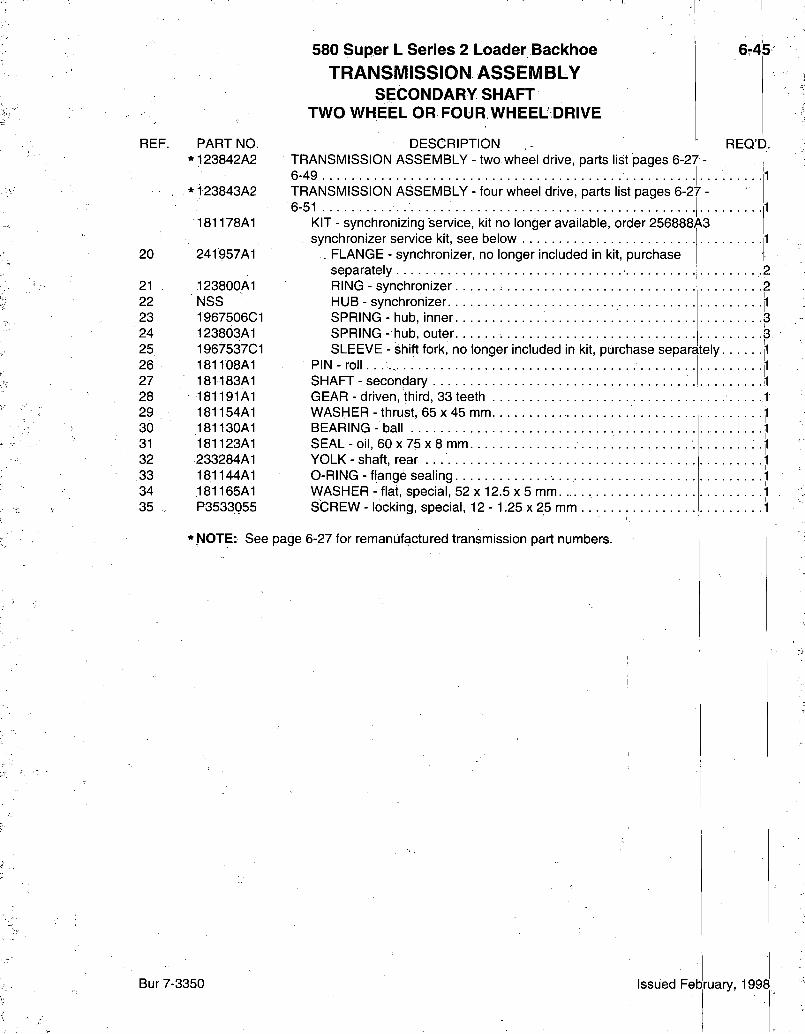
REF. PART NO. *123842A2
* 123843A2
181178A1
20 241957A1
21 123800A1 22 NSS 23 1967506C1 24 123803A1 25 1967537C1 26 181lb8A1 27 181183A1 28 181191A1 29 181154A1 30 181130A1 31 181123A1 32 233284A1 33 181144A1 34 181165A1 35 P3533055
580 Super L Series 2 Loader Bacl<hoe TRANSMISSION ASSEMBLY
SECONDARY SHAFT TWO WHEEL OR FOUR WHEEL DRIVE
DESCRIPTION TRANSMISSION ASSEMBLY - two wheel drive, parts list pages 6-27 6-49 TRANSMISSION ASSEMBLY - four wheel drive, parts list pages 6-27 6-51 1 -
KIT - synchronizing service, kit no longer available, order 256888A3 synchronizer service kit, see below
. FLANGE - synchronizer, no longer included in kit, purchase separately RING - synchronizer HUB - synchronizer SPRING - hub, inner SPRING - hub, outer SLEEVE - shift fork, no longer included in kit, purchase separately
P I N - r o l l . . . . . . . . SHAFT - secondary GEAR - driven, third, 33 teeth WASHER - thrust, 65 x 45 mm BEARING - ball SEAL - oil, 60 X 75 X 8 mm YOLK - shaft, rear 0-RING - flange sealing WASHER - flat, special, 52 x 12.5 x 5 mm SCREW - locking, special, 12 - 1.25 x 25 mm
6-45
REQ'D.
*.NOTE: See page 6-27 for remanufactured transmission part numbers.
Bur 7-3350 Issued February, 1998
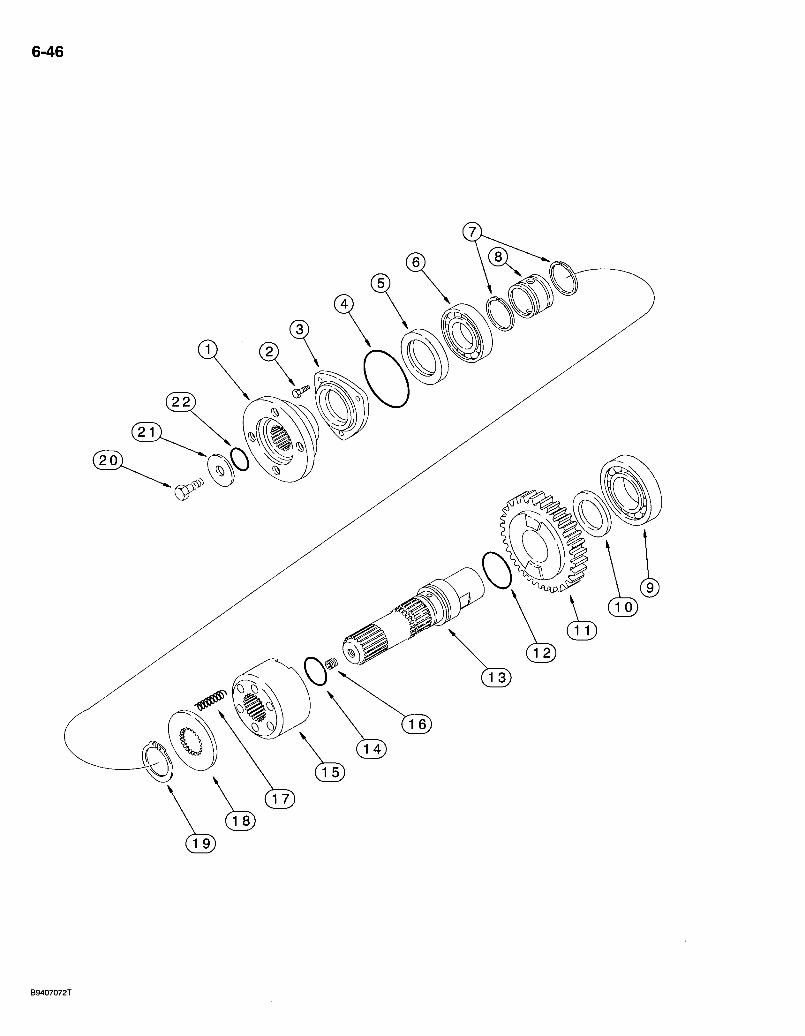
6-46
0
B9407072T
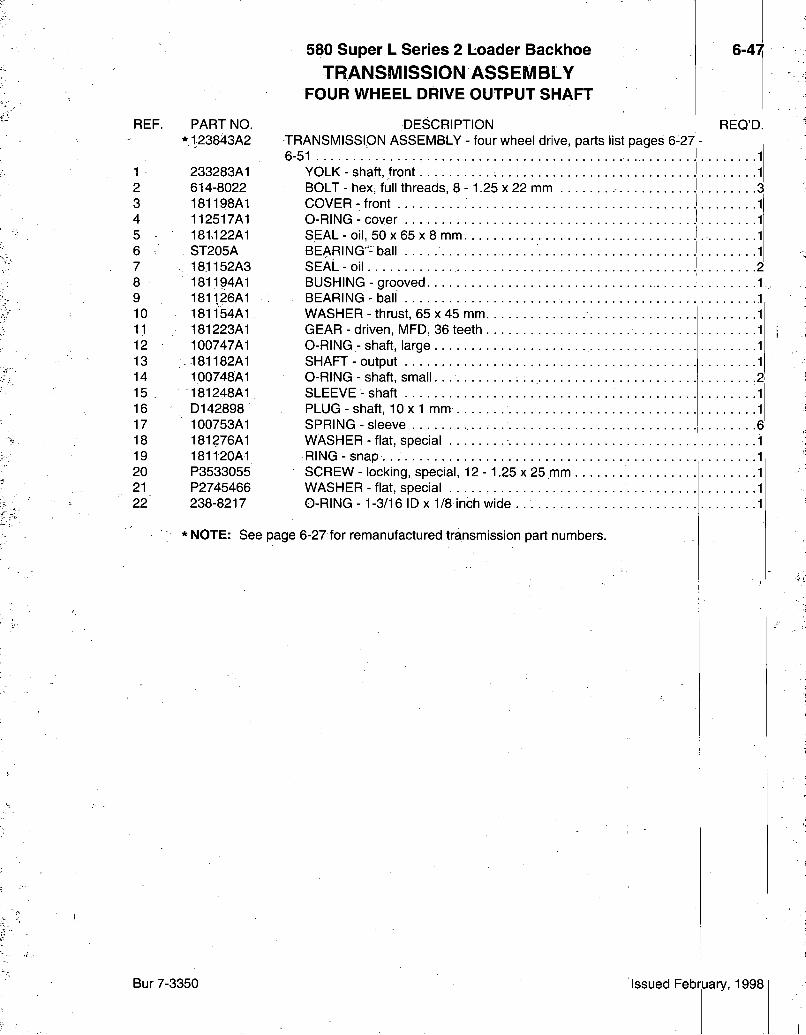
REF. PART NO. *123843A2
1 233283A1 2 614-8022 3 181198A1 4 112517A1 5 181.122A1 6 ST205A 7 ., 181152A3 8 181194A1 9 181126A1 10 18 l i 54A1 11 181223A1 12 100747A1 13 181182A1 14 100748A1 15 . 181248A1 16 D142898 17 100753A1 18 181276A1 19 181120A1 20 P3533055 21 P2745466 22 238-8217
580 Super L Series 2 Loader Backhoe TRANSMISSION ASSEMBLY
FOUR WHEEL DRIVE OUTPUT SHAFT
DESCRIPTION TRANSMISSION ASSEMBLY - four wheel drive, parts list pages 6-27 6-51 • •
YOLK - shaft, front BOLT - hex, full threads, 8 - 1.25 x 22 mm COVER - front O-RING - cover SEAL - oil, 50 X 65 X 8 mm BEARING- ball SEAL-o i l BUSHING - grooved BEARING-bal l WASHER - thrust, 65 x 45 mm GEAR - driven, MFD, 36 teeth O-RlNG - shaft, large SHAFT-output O-RING - shaft, small SLEEVE-shaf t PLUG-shaf t , 1 0 x 1 mm SPRING - sleeve WASHER - flat, special RING - snap SCREW - locking, special, 12 - 1.25 x 25 mm WASHER - fiat, special . O-RING -1-3/16 ID X 1/8 inch wide .
6-47
REQ'D
* NOTE: See page 6-27 for remanufactured transmission part numbers.
Bur 7-3350 Issued February, 1998
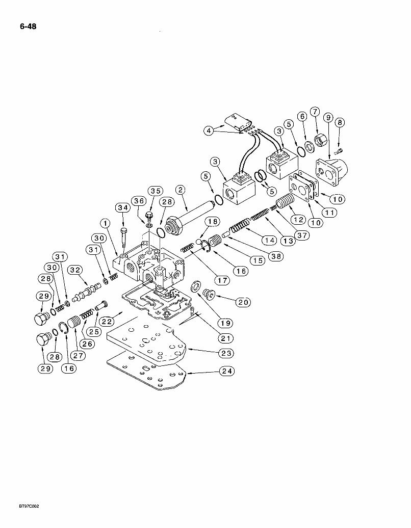
6-48
29) (Te)
BT97C002
REF. PART NO. *123842A2
*123843A2
190434A1 1 NSS 2 190442A1 3 190443A1 4 190437A1 5 " 181136A1 6 181273A1 7 181272A1 8 864-6020 9 181251A1 10 181256A1 11 190439A1 12 190438A1 13 190435A1 14 190441A1 15 181234A1 16 299324A1 17 181261A1 18 181146A1 19 181107A1 20 181103A1 21 864-8020 22 181166A1 23 181207A1 24 181208A1 25 181254A1 26 181260A1 27 181255A1 28 181137A1 29 181258A1 30 181262A1 31 181253A1 32 190444A1 34 814-8080 35 181100A1 36 934667R1 37 190436A1 38 190440A1
580 Super L Series 2 Loader Backhoe TRANSMISSION ASSEMBLY
TRANSMISSION CONTROL VALVE TWO WHEEL OR FOUR WHEEL DRIVE
DESCRIPTION TRANSMISSION ASSEMBLY - two wheel drive, parts list pages 6-27 -6-49 TRANSMISSION ASSEMBLY - four wheel drive, parts list pages 6-27 -6-51
VALVE ASSEMBLY - transmission control BODY - transmission control valve PLUNGER - solenoid
6-49
REQ'D.
• l" COIL - solenoid ^ CONNECTOR - solenoid } 0-RING - sealing • • -f WASHER - sealing, copper I PLUG-hex, cap } BOLT - hex socket, 6 -1.0 x 20 mm f COVER - modulation • • '} GASKET-cover ? SPACER - gasket } PISTON - modulation, outer } SPRING - inner. •} SPRING - outer •} PISTON - modulation, inner 1 RING - snap ? SPRING - check 1 BALL-check ^ 1 WASHER - sealing, copper: 1 PLUG-oil 1 BOLT - hex socket, 8 - 1.25 x 20 mm -3 GASKET - body to valve plate 1 PLATE-valve 1 GASKET - valve plate to transmission housing 1 SHAFT - flow divider ] SPRING - piston 1 PISTON - flow divider 1 0-RING-plug 3 PLUG - valve ? SPRING - spool 2 SPACER - spring 2 SPOOL - fonward/reverse 1 BOLT - hex, 8 - 1.25 x 80 mm • • -6 PLUG - valve. . 1 WASHER - flat, copper, special, 10 x 14 x 1.5 mm 4 SPRING - piston, outer modulation lj PIN - piston, inner modulation "li
' NOTE: See page 6-27 for remanufactured transmission part numbers.
Bur 7-3350 Issued February, 1998
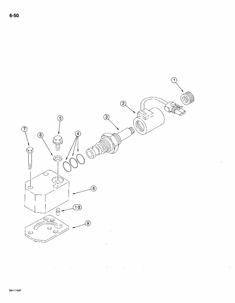
6-50
REF. PART NO. *123843A2
580 Super L Series 2 Loader Backhoe 6-51 TRANSMISSION ASSEMBLY
SOLENOID VALVE - FOUR WHEEL DRIVE
DESCRIPTION REQ'D. TRANSMISSION ASSEMBLY - four wheel drive, parts list;pages 6-27 -6-51
190432A1 VALVE ASSEMBLY - solenoid 1 NSS NUT-cap 2 NSS COIL - solenoid 3 NSS VALVE - solenoid . . 4 181149A1 KIT - seal, solenoid, includes (1 each) 238-5014, 238-5015 and
237-6010 0-ring, not available for service, order 190432A1 valve 5 181100A1 PLUG - valve 6 934667R1 WASHER - fiat, copper, special, 10 x 14 x 1.5 mm 7 814-8060 BOLT - hex, 8 - 1.25 x 60 mm r 8 190429A1 BODY - solenoid valve 9 190430A1 GASKET - body to transmission housing 10 190431A1 VALVE - solenoid, installed between item 8 and item 9:
* NOTE: See page 6-27 for remanufactured transmission part numbers.
Bur 7-3350 Issued February, 1998
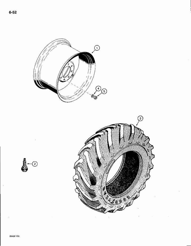
6-52
^l•v'••^v>;,••'-•^rfi^^
B9408129S
REF.
1 2 3
1 2 3
4 5
PART NO.
104907A1 A20058 REF
119241A1 A20058 REF
D138380 D138492
580 Super L Series 2 Loader Backhoe REAR WHEELS AND TIRES
TWO WHEEL OR FOUR WHEEL DRIVE
DESCRIPTION
19.5LX24 TIRES-10 PLY
6-53
REO'D.
WHEEL-rim 2 VALVE - stem, wheel 2 TIRE - rear, purchase locally. 2
17.5LX24TIRES-10PLY
WHEEL - rim 2 VALVE - stem, wheel .2 TIRE - rear, purchase locally 2
WHEEL NUTS
WASHER - flat, hardened, special 20 NUT - hex, special, 22 mm -1.5 . .20
Bur 7-3350 Issued February, 1998
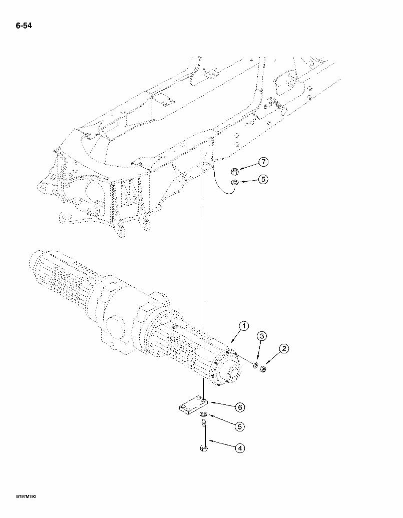
6-54
BT97M190
580 Super L Series 2 Loader Baickhoe REAR DRIVE A X L E MOUNTING
6r55
REF. PART NO. 1 279169A1 2 D.I 38492 3 ,D138380 4 827-20230 5 896-11020 6 117933A1 7 829-1420
DESCRIPTION REQ'D. AXLE ASSEMBLY - rear drive, parts list pages 6-59 - 6-67, 7-3 and 7-5 .1 NUT - hex, special, 22 mm -1.5 20 WASHER - flat, hardened, special 20 BOLT - hex, 20 - 2.5 x 230 mm, class 10.9 8 WASHER - flat, 22 x 37 x 4 mm, hardened • -16 PLATE - axle mouhting 2 NUT - hex, 20 mm - 2.5, class 10 8
Bur 7-3350 Issued February, 1998
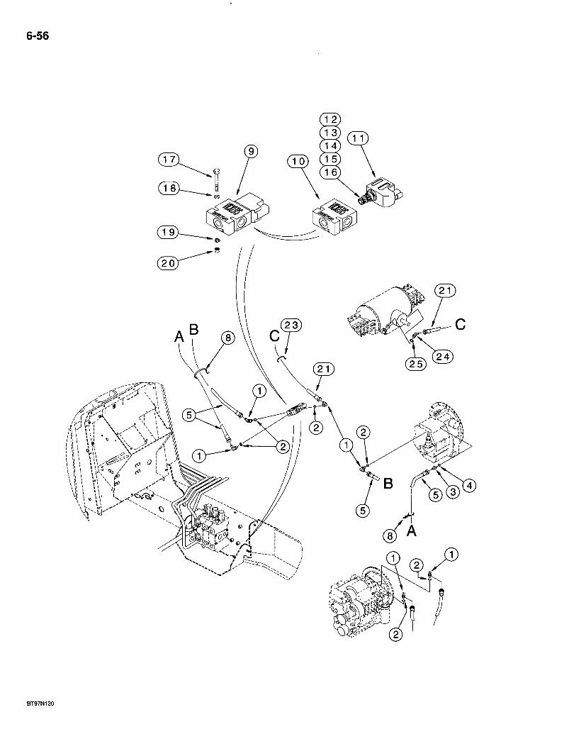
6-56
'•Am
BT97N120
580 Super L Series 2 Loader Backhoe REAR AXLE DIFFERENTIAL LOCK
6-57
REF. 1
2 3 4 5
8 9 10 11 12 13 14 15
16 17 18 19 20 21 23 24
25
PART NO. 218-5105
237-6006 218-5057 237-6006 304019A1
L18337 283579A1 297255A1 184505A1 237- 6008 238- 5013 238-5014 NSS
NSS 614-6050 895-11006 892-11006 829-1406 304020A1 LI 8337 218-5135
237-6006
DESCRIPTION REQ'D. ELBOW - 90 degree, 9/16-18 inch flare x adj 0-ring boss, four used on models without powershift transmissions; five used on models with powershift transmissions 4-5
0-RING -15/32 ID x 5/64 inch wide 1 ADAPTER - straight, 9/16-18 inch flare x 0-ring boss 1
0-RING -15/32 ID x 5/64 inch wide 1 HOSE - 1200 mm (47-1/4 inch) long, transmission supply and return lines, transmission to solenoid valve 2 STRAP-tie, 15 inch 2 VALVE ASSEMBLY - solenoid, differential lock 1
MANIFOLD - valve 1 SOLENOID ASSEMBLY - valve, 12 volt 1
0-RING - 41/64 ID x 3/32 inch wide 1 0-RING - 7/16 ID X 1/16 inch wide 1 O-RING -1/2 ID X 1/16 inch wide 1 VALVE - solenoid, cartridge, component parts are not serviced separately 1 COIL - solenoid 1
BOLT - hex, full threads, 6 -1.0 x 50 mm 2 WASHER - flat, 6.6 x 12 x 1.6 mm 2 WASHER - lock, 6 mm 2 NUT - hex, 6 mm -1.0, class 10 2 HOSE - 625 mm (24-5/8 inch) long, solenoid valve to rear axle 1 STRAP-tie, 15 inch 1 ELBOW - 45 degree, 9/16-18 inch flare x adj O-ring boss, axle port location shown is for models without powershift transmission; for models with powershift the elbow is located on the opposite side of the axle input shaft 1
0-RING -15/32 ID x 5/64 inch wide 1
Bur 7-3350 Issued February, 1998
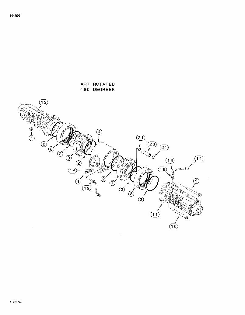
6-58
ART ROTATED 180 DEGREES
BT97M192
580 Super L Series 2 Loader Backhoe 6-59 REAR DRIVE AXLE
AXLE HOUSING
REF. PART NO. 279169A1
1 100557A1 1A 238-6121 2 238-5270 3 190457A2 4 295114A1 7 190458A2 8 190459A1 9 814-14140 10 864-12130 11 295108A1 12 295109A1 13 1966149C2 14 175955A1 18 El 35750 19 192481A1 20 222688A1 21 100760A1
DESCRIPTION REQ'D. AXLE ASSEMBLY - rear drive, parts list pages 6-59 - 6-67, 7-3 and 7-5 . . . . . . .1
PLUG - drain • • -2 0-RING -1-1/16 ID x 3/32 inch wide • -I
O-RING - 9 ID X 1/8 inch wide • • -6 CYLINDER - brake, right-hand 1 HOUSING - center, axle • • •-1 CYLINDER - brake, left-hand 1 SLEEVE - gear housing 2 BOLT - hex, 14 - 2.0 x 140 mm • • -22 BOLT - hex socket, 12 - 1.75 x 130 mm 4 HOUSING - axle, left-hand side HOUSING - axle, right-hand side BREATHER - axle housing COVER - breather, if used f-EXTENSION - breather SWITCH - oil temperature, may have one or two wires^ TUBE ^ internal: O-RING - sealing, tube 2
Bur7-3350 Issued February, 1998
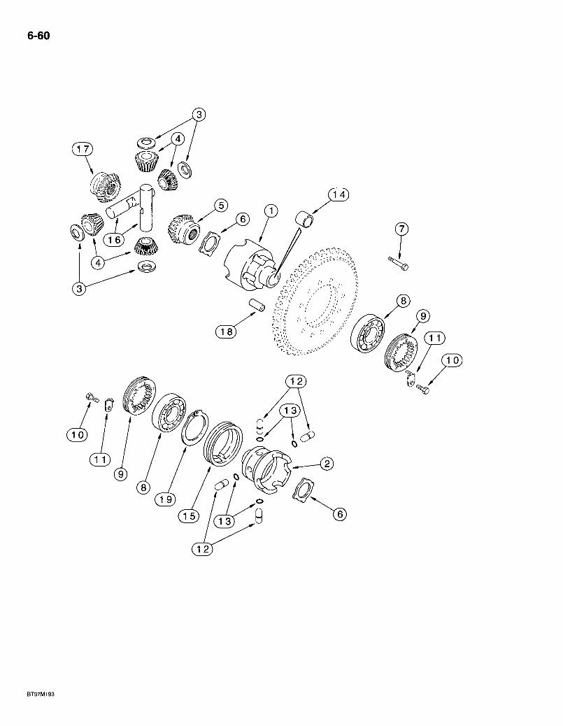
6-60
1 8

580 Super L Series 2 Loader Backhoe REAR DRIVE AXLE
DIFFERENTIAL
6-61
REF.
1 2 3 4
6 7 8 9 10 11 12 13 14 15 16
17
18 19
PART NO. DESCRIPTION REO'D. 279169A1 AXLE ASSEMBLY - rear drive, parts list pages 6-59 - 6-67, 7-3 and 7-5 1 292268A1 HOUSING ASSEMBLY - differential 1 NSS HOUSING - differential, flange half 1 NSS HOUSING - differential, plain half 1
* E135777 WASH E R - th rust 4 * 190471A1 GEAR - sun, 12 teeth, no longer sold separately, must be replaced
as a set, for service order 294192A1 gear set, see below 4 * D142971 GEAR - side, pinion, no longer sold separately, must be replaced as
a set, for service order 294192A1 gear set, see below 1 * 190469A1 WASHER - thrust 2
S300976 BOLT - hex, special, 12 - 1.75 x 90 mm, class 12.9 10 El 35785 BEARING - cup and cone 2 P3034505 RING - locking, threaded 2 112486A1 BOLT - hex, self-locking, special, 6 - 1 x 12 mm 2 175959A1 BRACKET - lock 2 292207A1 PIN - housing 4 292208A1 O-RING-pin 4 190452A1 BUSHING - housing 2 191067A1 SLEEVE - housing 1
* 190468A1 SHAFT - sun gear, no longer sold separately, must be replaced as a set, for service order 294192A1 gear set, see below 2
*292890A1 GEAR - side pinion, no longer sold separately, must be replaced as a set, for service order 294192A1 gear set, see below 1
D143033 PIN - dowel, 12 x 40 mm 2 175961A1 RING-lock 1
*294192A1 SET - gear, differential, service replacement, includes items 3-6, 16 and 17 1
Bur 7-3350 Issued February, 1998
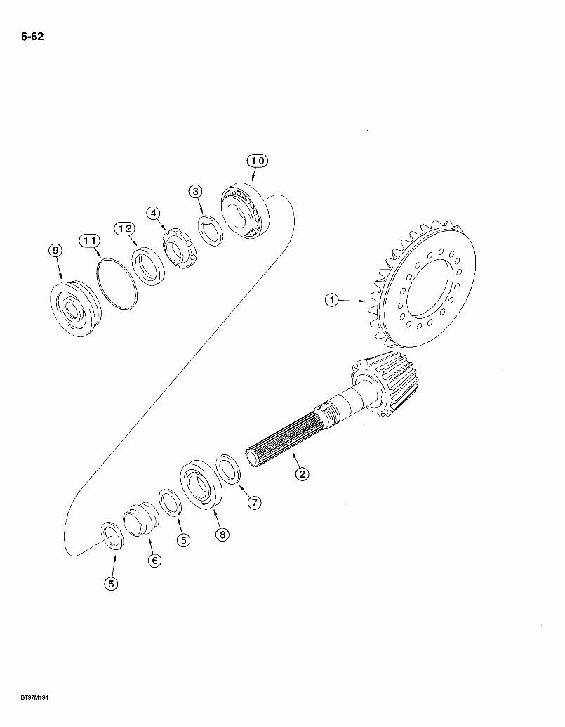
6-62
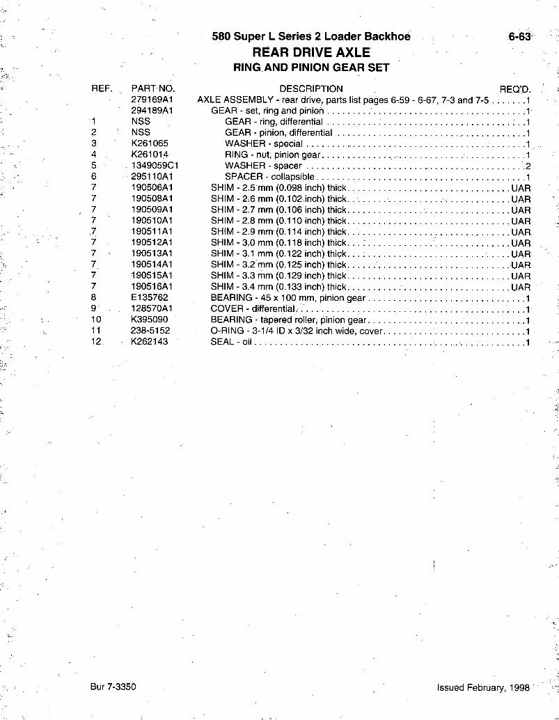
REF.
1 2 3 4 5 6 7 7 7 7 ,7 7 7 7 7 7 8 9 10 11 12,
PART NO. 279169A1 294189A1 NSS NSS K261065 K261014 1349059C1 295110A1 190506A1 190508A1 190509A1 190510A1 190511A1 190512A1 190513A1 190514A1 190515A1 190516A1 El 35762 128570A1 K395090 238-5152 K262143
580 Super L Series 2 Loader Backhoe REAR DRIVE A X L E
RING AND PINION GEAR SET
6-63
REQ'D. DESCRIPTION AXLE ASSEMBLY - rear drive, parts list pages 6-59 - 6-67, 7-3 and 7-5
GEAR - set, ring and pinion GEAR - ring, differential GEAR - pinion, differential WASHER - special RING - nut, pinion gear WASHER - spacer • -2 SPACER - collapsible ^
SHIM -2.5 mm (0.098 SHIM-2.6 mm (0.102 SHIM-2.7 mm (0.106 SHIM-2.8 mm (0.110 SHIM-2.9 mm (0.114 SHIM-3.0 mm (0.118 SHIM-3.1 mm (0.122 SHIM-3.2 mm (0.125 SHIM-3.3 mm (0.129 SHIM-3.4 mm (0.133
nch) thick nch) thick.. UAR nch) thick. UAR nch) thick nch) thick./. UAR nch) th ick. . . ; UAR nch) thick. UAR nch)thick nch) th i ck . . . . . -y^" nch) thick. ^ ' ^^
BEARING - 45 X 100 mm, pinion gear. . . . COVER - differential. . . . BEARING - tapered roller, pinion gear. . . . O-RING - 3-1/4 ID X 3/32 inch wide, cover. SEAL - o i l . . . . . . .
Bur 7-3350 Issued February, 1998
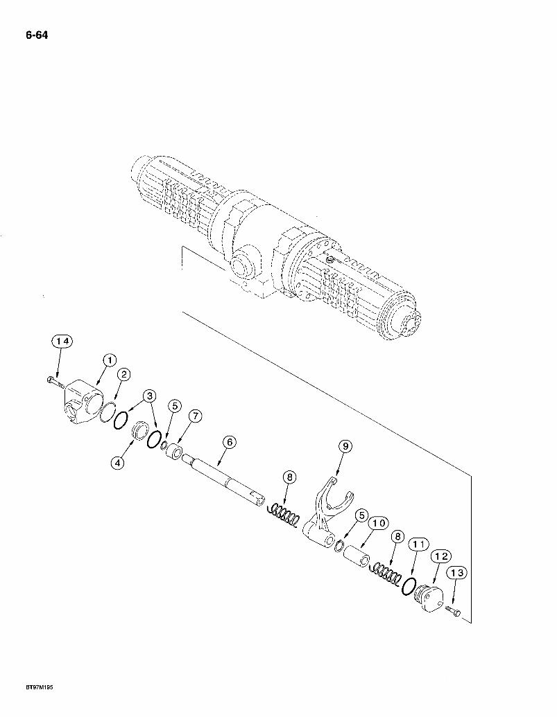
6-64
la c
BT97M195
580 Super L Series 2 Loader Backhoe REAR DRIVE AXLE DIFFERENTIAL LOCK
6-65
REF. PART NO. 279169A1
1 29^213A1 2 305152A1 3 292210A1 4 292212A1 5 •800-5120 6 292214A1 7 292902A1 8 175966A1 9 175964A2 10 175965A1 11 128376A1 12 175968A1 13 614-8030 14 814-8080
DESCRIPTION REQ'D. AXLE ASSEMBLY - rear drive, parts list pages 6-59 - 6-67, 7-3 and 7-5 1
CYLINDER - differential lock . 1 0-RING - cylinder. .1 O-RING - seal, external, piston .2 PISTON - differential lock • -I RING - external heavy retaining. No. 20 . • SHAFT - rail, shifter fork 1 BUSHING - shaft 1 SPRING -shaft. . .....2 FORK - shift 1 BUSHING - rail "> O-RING - cover • • 1 COVER - housing 1 BOLT - hex, full threads, 8 -1.25 x 30 mm 2 BOLT - hex, 8 -1.25 x 80 mm , .2
Bur 7-3350 Issued February, 1998

6-66
V)J (22) ^ / (22) C24
BT97N056
580 Super L Series 2 Loader Backhoe REAR DRIVE AXLE
PLANETARY
6-67
REF. PART NO. 279169A1
1 175974A1 2 D142986 2 196090A1 3 P2930467 4 175976A1 5 292891A1 6 . NSS 7 100557A1 7A 238-6121 8 K395082 9 K395093 10 ' 292893A1
11 292894A1 12 292898A1 13 247550A1 14 175982A1 15 K395131 17 107071A1 18 295580A1 19 175984A1 20 NSS
21 196065A1 22 196066A1 23 292896A1 24 247877A1 25 K395101 26 800-2136 27 292900A1 28 292899A1 29 292901A1
DESCRIPTION REQ'D. AXLE ASSEMBLY - rear drive, parts list pages 6-59 - 6-67, 7-3 and 7-5 1
HUB ASSEMBLY - wheel attaching .-. 2 STUD - special, without flanged collar 20 STUD - special, with collar, for recessed bolt holes, if used 20
O-RING -sealing 2 GEAR - ring, planetary 2
: CARRIER ASSEMBLY - planetary. 2 SHAFT - pinion gear 6
PLUG -drain 2 O-RING -1-1/16 ID X 3/32 inch wide, not shown . 1
SCREW - special, planetary cover plate 4 PIN - locking, planetary carrier 2 BEARING - needle (package of 10 needles) (372 needles required) planetary gear 38 GEAR - pinion, planetary 6 WASHER - thrust, pinion gear 6 BEARING - needle (package of 10 used as pins)(6 required) 1 BOLT - hex, self-locking, special, 1 0 - 1.25 x 50 mm, class 10.9 6 BOLT - hex head, special, 1 4 - 1.50 x 65 mm, self-locking 16 BUSHING - centering, 20 mm OD .16 HUB - ring gear 2 RING- lock . . . . . 2 COUPLING - drive, welded to and included with the differential brake oil auger • -2 BUSHING - axle housing, drive . .2 SEAL - oil, axle housing • .2 SHAFT - drive 2 SEAL - oil, cassette, replaces 1349265C1 seal 2 BEARING - ball, hub 4 RING - internal retaining. No. 36 2 WASHER - thrust, pinion gear, outer 6 WASHER - thrust, pinion gear, inner 6 WASHER - needle bearing s . 6
Bur 7-3350 Issued February, 1998
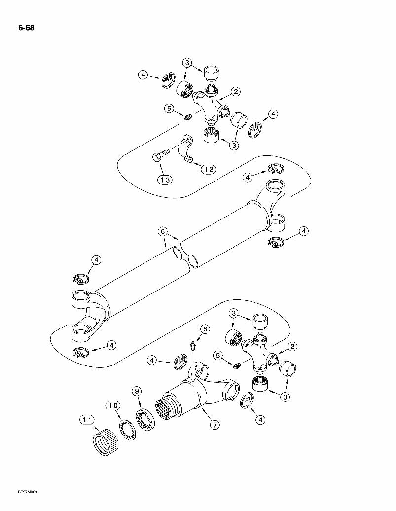
6-68
BT97M009
580 Super L Series 2 Loader Backhoe DRIVE SHAFT FOR REAR DRIVE AXLE
REAR DRIVE AXLE TO TRANSMISSION
6-69
REF. PART NO. 284712A1 144278A1
2 NSS 3 NSS 4 NSS 5 219-10 6 NSS 7 . 144279A1 8 219-10
D149860 9 NSS 10 NSS 11 NSS 12 90-6682T1
13 D137627
DESCRIPTION REQ'D. SHAFT ASSEMBLY - drive \ .1
KIT - universal joint 2 JOINT - universal, drive shaft 1 BEARING - universal joint. 4
• RING - retaining 4 FITTING - grease, straight, 1/4-28 taper x11/16 inch , .2 SHAFT - drive, transmission to rear axle :1 YOKE - tube, splined, to rear axle -I FITTING - grease, straight, 1/4-28 taper x 11/16 inch . .1 K IT-dus t cap. -I
WASHER-cork • • -1 WASHER-s tee l -1 CAP - dust seal retaihing 1
RETAINER - drive shaft, strap, not included in drive shaft assembly, purchase separately 2 BOLT - special 4
Bur 7-3350 Issued February, 1998

6-70
580 Super L Series 2 Loader Backhoe 7 1
ALPHABETICAL INDEX BRAKES
DESCRIPTION PAGE Differential Brake - Rear Axle ...7-3 Hydraulic Circuit 7-9 Master Cylinder 7-11 Master Cylinder Mounting 7-7 Parking Brake - Rear Axle 7-5 Parking Brake Lever and Linkage 7-13 Pedals 7-7
Bur 7-3350 Issued February, 1998
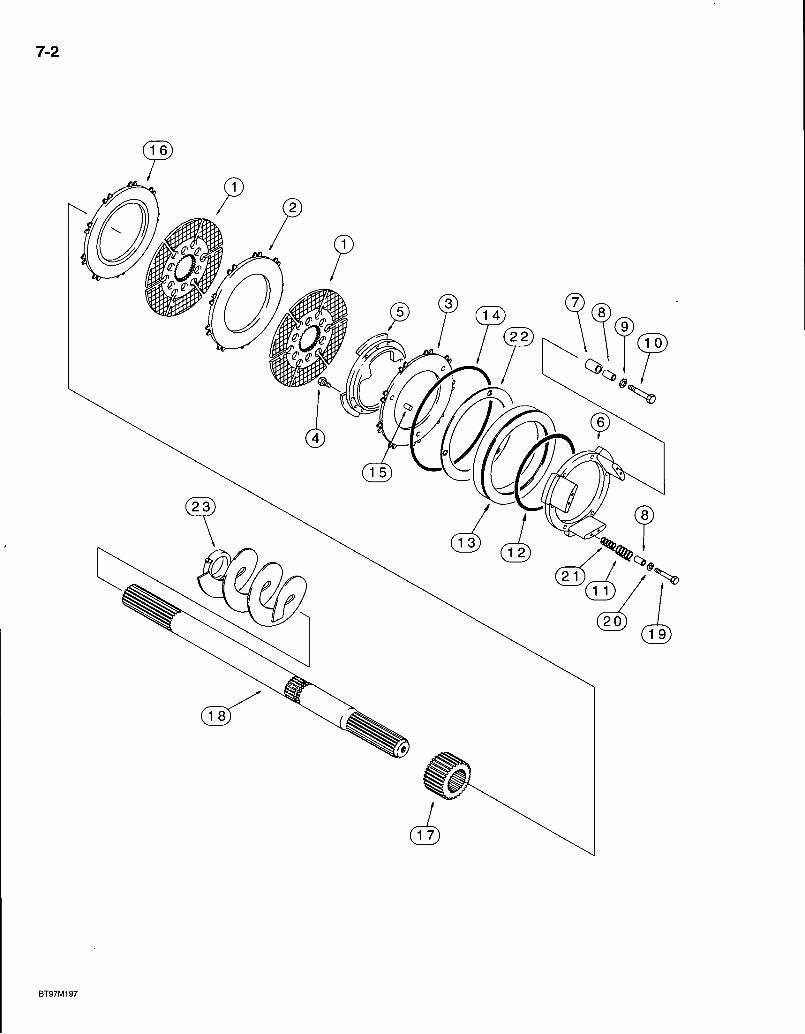
7-2
a
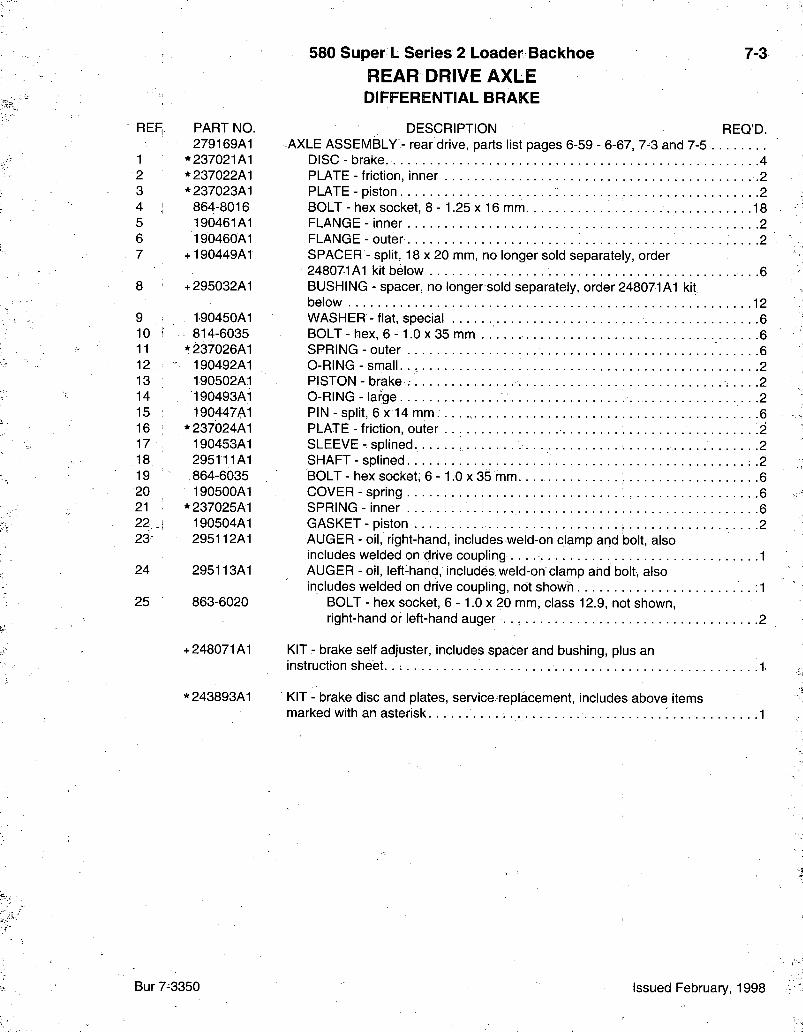
580 Super L Series 2 Loader Backhoe REAR DRIVE AXLE DIFFERENTIAL BRAKE
7-3
REF,. PART NO, 279169A1
1 * 237021A1 2 *237022A1 3 *237023A1 4 864-8016 5 190461A1 6 190460A1 7 +190449A1
8 +295032A1
9 190450A1 10 i 814-6035 11 *237026A1 12 190492A1 13 190502A1 14 190493A1 15 190447A1 16 *237024A1 17 190453A1 18 295111A1 19 .864-6035 20 190500A1 21 *237025A1 22 i 190504A1 23 295112A1
24 295113A1
25 863-6020
+248071A1
^243893A1
DESCRIPTION REQ'D. -AXLE ASSEMBLY - rear drive, parts list pages 6-59 - 6-67, 7-3 and 7-5
DISC - brake. 4 PLATE - friction, inner -2 PLATE - piston 2 BOLT - hex socket, 8 - 1.25 x 16 mm. 18 FLANGE - inner 2 FLANGE-outer 2 SPACER - split, 18 X 20 mm, no longer sold separately, order 248071A1 kit below . .6 BUSHING - spacer, no longer sold separately, order 248071A1 kit below 12 WASHER - flat, special 6 BOLT-hex , 6 - 1 . 0 x 3 5 mm 6 SPRING-outer 6 O-RING-smal l 2 PISTON - brake ; .2 O-RING-large • .2 PIN - split, 6 x 14 mm. .6 PLATE - friction, outer 2 SLEEVE -splined 2 SHAFT - splined .2 BOLT - hex socket, 6 -1 .0 x 35 mm 6 COVER - spring 6 SPRING - inner . .6 GASKET - piston 2 AUGER - oil, right-hand, includes weld-on clamp and bolt, also includes welded on drive coupling 1 AUGER - oil, left-hand, includes weld-oh clamp and bolt, also includes welded on drive coupling, not shown :1
BOLT - hex socket, 6 -1 .0 x 20 mm, class 12.9, not shown, right-hand or left-hand auger 2
KIT - brake self adjuster, includes spacer and bushing, plus an instruction sheet. . : 1
KIT - brake disc and plates, service replacement, includes above items marked with an asterisk 1
Bur 7-3350 Issued February, 1998
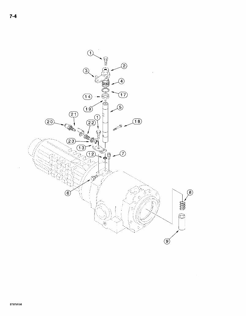
r-4
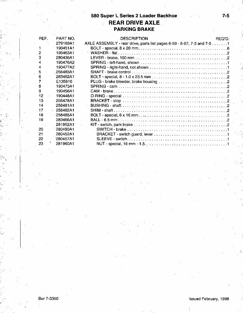
580 Super L Series 2 Loader Baclchoe REAR DRIVE AXLE
PARKING BRAKE
7-5
REF. PART NO. 279169A1
1 190451A1 2 190463A1 3 280436A1 4 190476A2 4 190477A2 5 256483A1 6 283462A1 7 E l 35810 8 190473A1 9 190456A1 12 190448A1 13 256478A1 14 256481A1 17 256482A1 18 256485A1 19 283466A1
281952A1 20 280450A1 21 280452A1 22 280457A1 23 ' 281960A1
DESCRIPTION REQ'D. AXLE ASSEMBLY - rear drive, parts list pages 6-59 - 6-67, 7-3 and 7-5 . . . . . . . 1
BOLT - special, 8 x 20 mm. 6 WASHER-f la t 2 LEVER-brake, 100mm 2 SPRING - left-hand, shown 1 SPRING - right-hand, not shown 1 SHAFT - brake control 2 BOLT - special, 8 -1 .0 x 23.5 mm 2 PLUG - brake bleeder, brake housing • -2 SPRING-cam 2 CAM - brake 2 O-RING - special 2 BRACKET-stop . • • .2. BUSHING - shaft : • • -2 SHIM- shaft 2 BOLT- special, 6 X 16 mm. . 2 BALL - 6.5 mm 2 KIT - switch, park brake 2
SWITCH-brake 1 BRACKET - switch guard, lever 1 SLEEVE - switch 1 NUT - special, 16 mm -1 .5 1
Bur 7-3350 Issued February, 1998
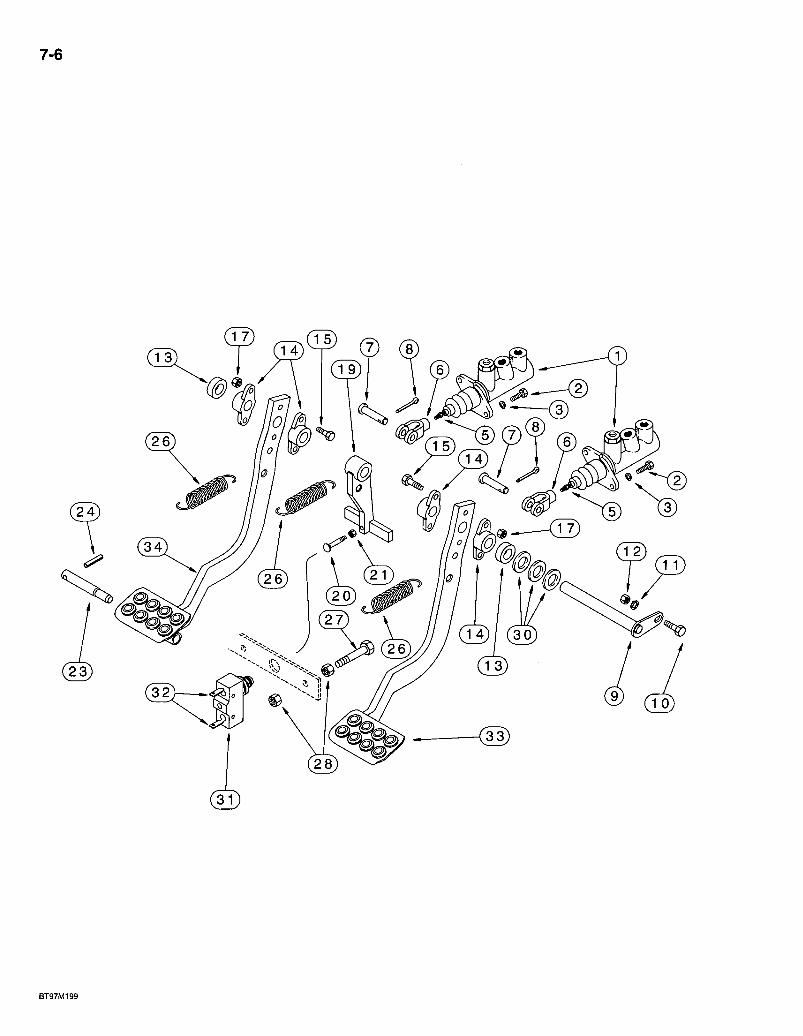
7-6
& ( 3 0
BT97M199
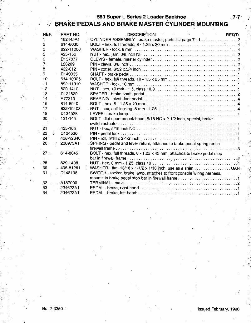
580 Super L Series 2 Loader Backhoe B R A K E PEDALS AND BRAKE MASTER CYLINDER MOUNTING
7-7
REF. PART NO. 1 182445A1 2 614-8030 3 892-11008 5 425-156 6 D137077 7 L26209 8 432-612 9 D140035 10 614-10025 11 892-11010 12 829-1410 13 .D124529 14 A77310 15 814-8040 17 832-10408 19 D124528 20 121-145
21 425-105 23 D124530 24 438-12040 26 230973A1
27 614-8045
28 829-1408 30 495-81261 31 D148108
32 , A 1 8 7 9 9 0 33 / 234623A1 34 234622A1
DESCRIPTION • REQ'D. CYLINDER ASSEMBLY - brake master, parts list page 7-11 . 2 BOLT - hex, full threads, 8 - 1.25 x 30 mm 4 WASHER - lock, 8 mm • . -4 NUT - hex, jam, 3/8 inch NF .2 CLEVIS - female, master cy l inder. . . ; . 2 PIN - clevis, 3/8 inch .2 PIN - cotter, 3/32 x.3/4 inch 2 SHAFT-brake pedaL 1 BOLT-hex , full threads, 10 -1 .5 x 25 mm 1 WASHER - lock, 10 mm 1 NUT - hex, 10 mrii -1 .5 , class 1 0 . 9 . . . . 1 SPACER - brake shaft, pedal 2 BEARING - pivot, foot pedal 4 BOLT - hex, 8 - 1.25 x 40 mrh 4 NUT - hex, self-locking, 8 mm -1.25 4 LEVER-brake lamp 1 BOLT - flat countersunk head, 5/16 NC x 2-1/2 inch, special, brake switch actuator • •'I NUT - hex, 5/16 inch NC 1 PIN-pedal lock • •-1 PIN- ro i l , 5 /16x2-1/2 inch 1 SPRING - pedal and lever return, attaches to brake pedal spring rod in firewall frame : .3 BOLT - hex, full threads, 8 - 1.25 x 45 mm, attaches to brake pedal stop bar in firewall frame 2 NUT - hex, 8 mm -1.25, class 10 '4 WASHER - flat, 13 /16x1-1 /2x1 /16 inch, use as a shim UAR SWITCH - rocker, brake lamp, attaches to front console wiring harness, mounts in brake pedal stop bar in firewall frame • • - I tERMINAL-ma le 2 PEDAL - brake, right-hand 1 PEDAL - brake, left-hand . .1
Bur 7-3350 Issued February, 1998
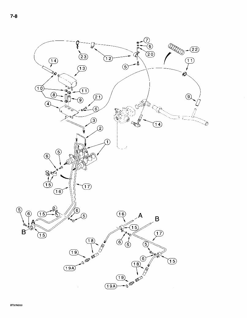
7-8
0
(T9A)—
BT97MK«
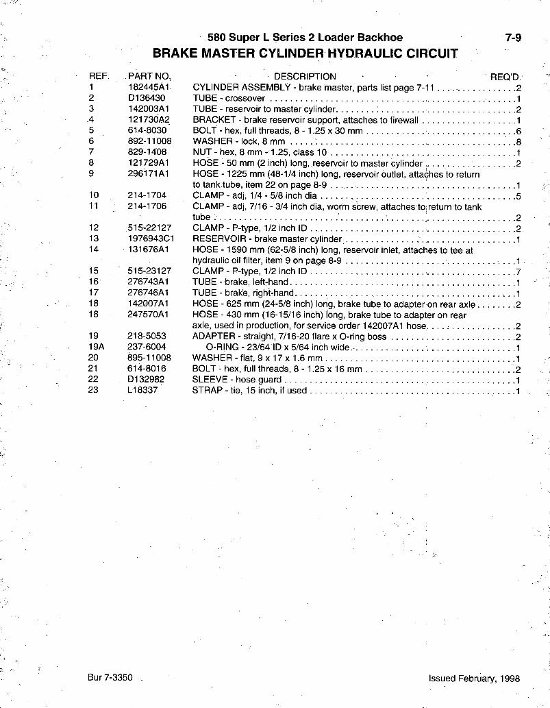
580 Super L Series 2 Loader Backhoe BRAKE MASTER CYLINDER HYDRAULIC CIRCUIT
7-9
REF. PART NO, 1 182445A1 2 D136430 3 142003A1 A 121730A2 5 614-8030 6 892-11008 7 829-1408 8 121729A1 9 296171A1
10 214-1704 11 214-1706
12 515-22127 13 1976943C1 14 131676A1
15 515-23127 16 276743A1 17 276746A1 18 142007A1 18 247570A1
19 218-5053 19A 237-6004 20 895-11008 21 614-8016 22 D132982 23 LI 8337
DESCRIPTION REQ'D. CYLINDER ASSEMBLY - brake master, parts list page 7 - 1 1 . . . . 2 TUBE - crossover 1 TUBE - reservoir to master cylinder 2 BRACKET - brake reservoir support, attaches to firewall 1 BOLT - hex, full threads, 8 - 1.25 x 30 mm 6 WASHER - lock, 8 mm 8 NUT - hex, 8 mm -1.25, class 10 1 HOSE - 50 mm (2 inch) long, reservoir to master cylinder 2 HOSE -1225 mm (48-1/4 inch) long, reservoir outlet, attaches to return to tank tube, item 22 on page 8-9 1 CLAMP - adj, 1/4 - 5/8 inch dia . . . . . . . . . . 5 CLAMP - adj, 7/16 - 3/4 inch dia, worm screw, attaches to, return to tank tube : [. 2 CLAMP - P-type, 1/2 inch ID 2 RESERVOIR - brake master cylinder 1 HOSE - 1590 mm (62-5/8 inch) long, reservoir inlet, attaches to tee at hydraulic oil filter, item 9 on page 8-9 .1 CLAMP - P-type, 1/2 inch ID 7 T U B E - brake, left-hand 1 TUBE - brake, right-hand .1 HOSE - 625 mm (24-5/8 inch) long, brake tube to adapter on rear axle 2 HOSE - 430 mm (16-15/16 inch) long, brake tube to adapter on rear axle, used in production, for service order 142007A1 hose. . . . : 2 ADAPTER - straight, 7/16-20 flare x 0-ring boss .2
0-RING - 23/64 ID x 5/64 inch wide.- 1 WASHER - flat, 9 x 17 x 1.6 mm ,1 BOLT - hex, full threads, 8 - 1.25 x 16 mm 2 SLEEVE - hose guard 1 STRAP - tie, 15 inch, if used .1
Bur 7-3350 Issued February, 1998
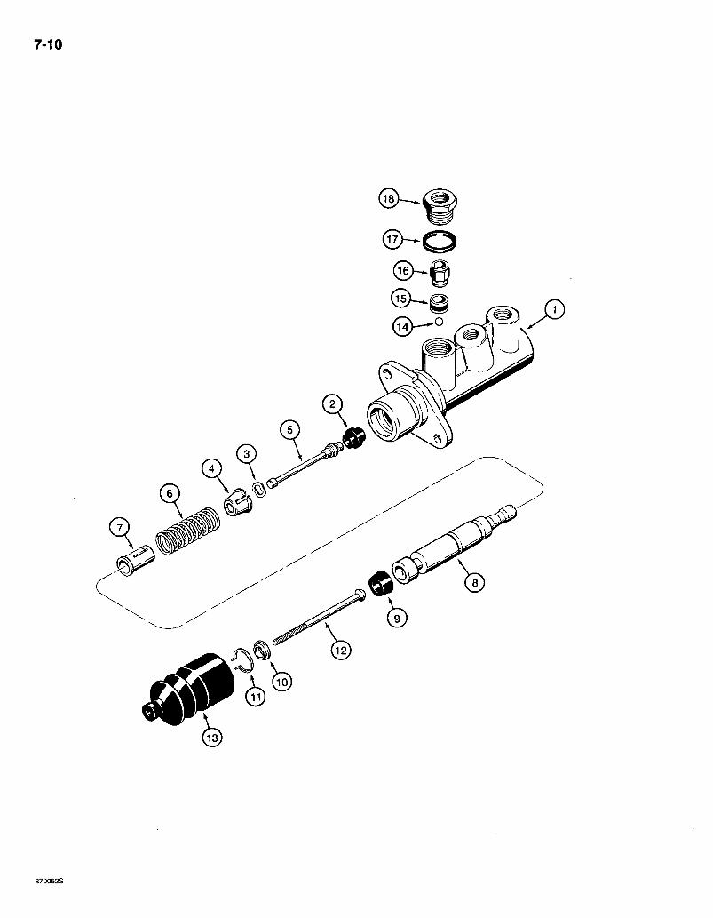
7-10
870052S
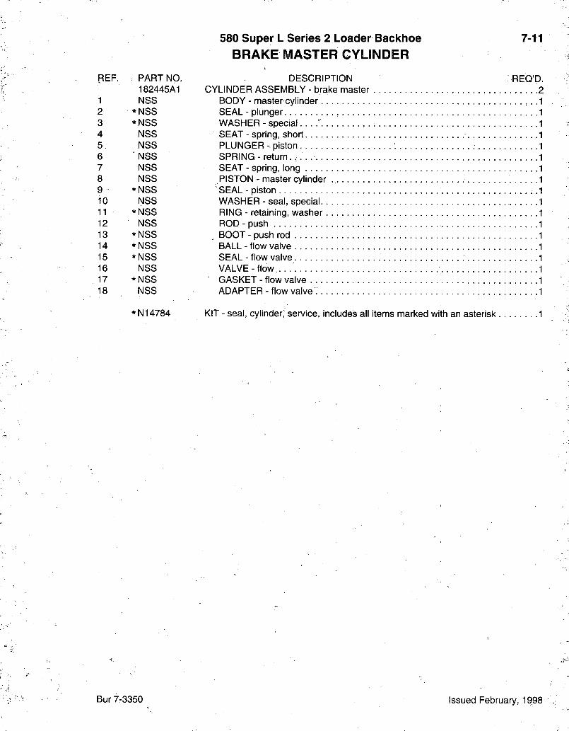
580 Super L Series 2 Loader Backhoe 7-11 BRAKE MASTER CYLINDER
REF. PART NO. DESCRIPTION REQ'D^ 182445A1 CYLINDER ASSEMBLY - brake master 2
1 NSS BODY - master cylinder 2 * NSS SEAL - plunger 3 * NSS WASHER - special ' 4 NSS SEAT - spring, short 5 NSS PLUNGER - piston 6 NSS SPRING - return. 7 NSS SEAT - spring, long 8 NSS PISTON - master cylinder 9 *NSS SEAL - piston 10 NSS WASHER - seal, special 11 *NSS RING - retaining, washer 12 NSS ROD - push 13 * NSS BOOT - push rod 14 * NSS BALL - flow valve 15 * NSS SEAL - flow valve 16 NSS VALVE-flow. 17 *NSS GASKET-flow valve 18 NSS ADAPTER - flow valve
'N14784 KIT - seal, cylinder, service, includes all items marked with an asterisk 1
Bur 7-3350 Issued February, 1998
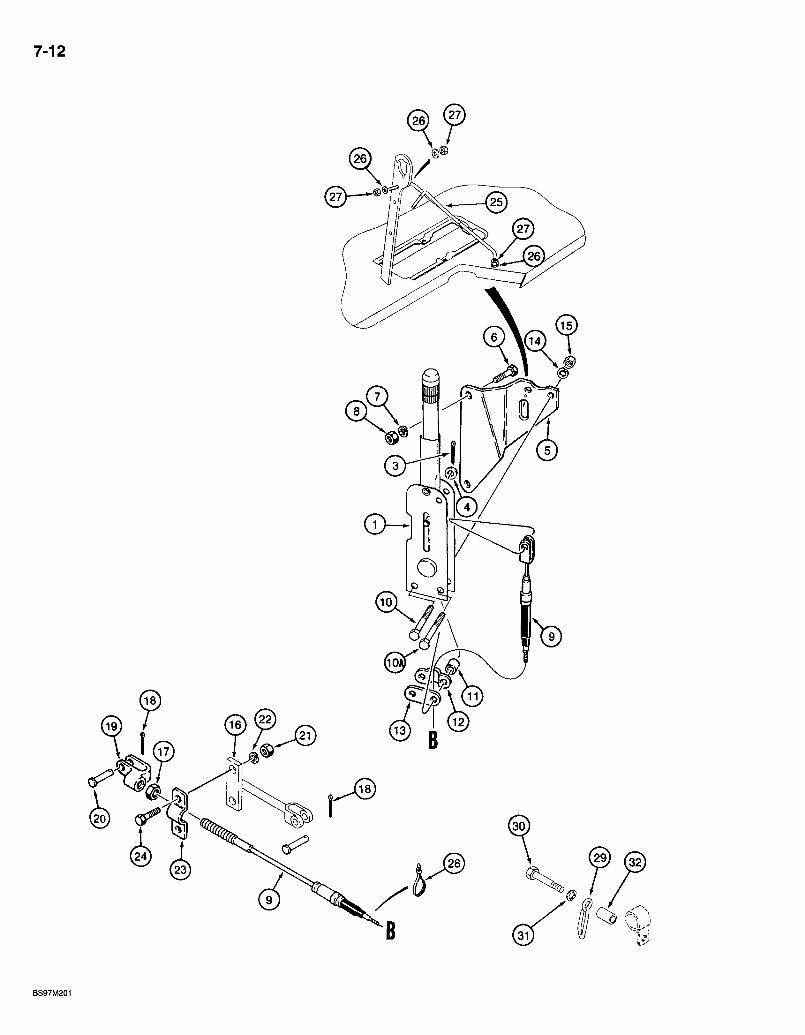
7-12
0
9,
@
BS97M201
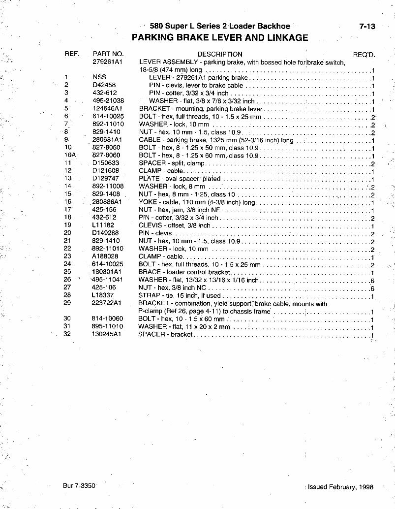
580 Super L Series 2 Loader Backhoe PARKING BRAKE LEVER AND LINKAGE
7-13
REF. PART NO. 279261A1
1 NSS 2 D42458 3 432-612 4 495-21038 5 124646A1 6 614-10025 7' 892-11010 8 829-1410 9 280681A1 10 827-8050 10A 827-8060 11 . . D150633 12 D121608 13 . D129747 14 892-11008 15 829-1408 16 280886A1 17 425-156 18 432-612 19 L11182 20 D149288 21 829-1410 22 892-11010 23 A188028 24 614-10025 25 180801A1 26 " '495-11041 27 425-106 28 LI 8337 29 223722A1
30 814-10060 31 895-11010 32 130245A1
DESCRIPTION REQ'D. LEVER ASSEMBLY - parking brake, with bossed hole for brake switch, 18-5/8 (474 mm) long 1
LEVER - 279261A1 parking brake 1 PIN - clevis, lever to brake cable 1 PIN - cotter, 3/32 x 3/4 inch 1 WASHER- flat, 3/8 x 7/8 x, 3/32 inch 1
BRACKET - mounting, parking brake lever 1 BOLT - hex, full threads, 10-1.5 x 25 mm 2 WASHER-lock, 10 mm 2 NUT-hex, 10 mm-1.5, class 10.9. 2 CABLE - parking brake, 1325 mm (52-3/16 inch) long 1 BOLT - hex, 8 - 1.25 x 50 mm, class 10.9 1 BOLT - hex, 8 - 1.25 x 60 mm, class 10.9 1 SPACER - split, damp 2 CLAMP-cable. 1 PLATE - oval spacer,' plated 1 WASHER - lock, 8 mm -2 NUT-hex, 8 mm-1:25, class 10 , 2 YOKE - cable, 110 mm (4-3/8 inch) long 1 NUT - hex, jam, 3/8 inch NF 1 PIN - cotter,-3/32 x 3/4 inch • 2 CLEVIS - offset, 3/8 inch 1 PIN - clevis : 2 NUT-hex, 10 mm-1.5, class 10.9 2 WASHER-lock, 10mm 2 CLAMP-cable. 1 BOLT-hex, full threads, 10- 1.5x25 mm .2 BRACE - loader control bracket 1 WASHER - flat, 13/32 x 13/16 x 1/16 inch. 6 NUT - hex, 3/8 inch NC 6 STRAP - tie, 15 inch, if used 1 BRACKET - combination, yield support, brake cable, mounts with P-clamp (Ref 26, page 4-11) to chassis frame • . .|. 1 BOLT - hex, 10 - 1.5 x 60 mm 1 WASHER - flat, 11 x 20 x 2 mm 1 SPACER - bracket 1
Bur 7-3350 Issued February, 1998
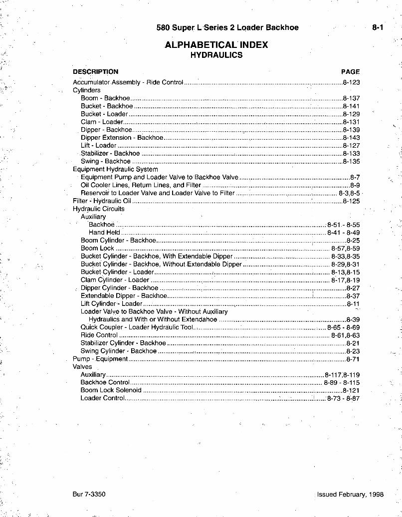
580 Super L Series 2 Loader Backhoe 8-1
ALPHABETICAL INDEX HYDRAULICS
DESCRIPTION PAGE Accumulator Assembly - Ride Control 8-123 Gylinders
Boom - Backhoe 8-137 Bucket - Backhoe 8-141 Bucket - Loader 8-129 Clam-Loader 8-131 Dipper- Backhoe , 8-139 Dipper Extension - Backhoe 8-143 Lift-Loader : 8-127 Stabilizer - Backhoe 8-133 Swing - Backhoe 8-135
Equipment Hydraulic System Equipment Pump and Loader Valve to Backhoe Valve 8-7 Oil Cooler Lines, Return Lines, and Filter 8-9 Reservoir to Loader Valve and Loader Valve to Filter 8-3,8-5
Filter - Hydraulic Oil 8-125 Hydraulic Circuits
Auxiliary Backhoe.. 8-51-8-55 Hand Held. 8-41-8-49
Boom Cylinder - Backhoe 8-25 Boom Lock 8-57;8-59 Bucket Cylinder - Backhoe, With Extendable Dipper 8-33,8-35 Bucket Cylinder - Backhoe, Without Extendable Dipper.. 8-29,8-31 Bucket Cylinder - Loader.. 8-13,8-15 Clam Cylinder - Loader 8-17,8-19
, Dipper Cylinder-Backhoe 8-27 Extendable Dipper - Backhoe i 8-37 Lift Cylinder - Loader..... 8-11 Loader Valve to Backhoe Valve - Without Auxiliary
Hydraulics and With or Without Extendahoe 8-39 Quick Coupler - Loader Hydraiulic Tool... 8-65 - 8-69 Ride Control 8-61,8-63 Stabilizer Cylinder - Backhoe 8-21 Swing Cylinder - Backhoe 8-23
Pump - Equipment 8-71 Valves
Auxiliary 8-117,8-119 Backhoe Control 8-89 - 8-115 Boom Lock Solenoid 8-121 Loader Control 1 8-73 - 8-87
Bur 7-3350 1 Issued February, 1998
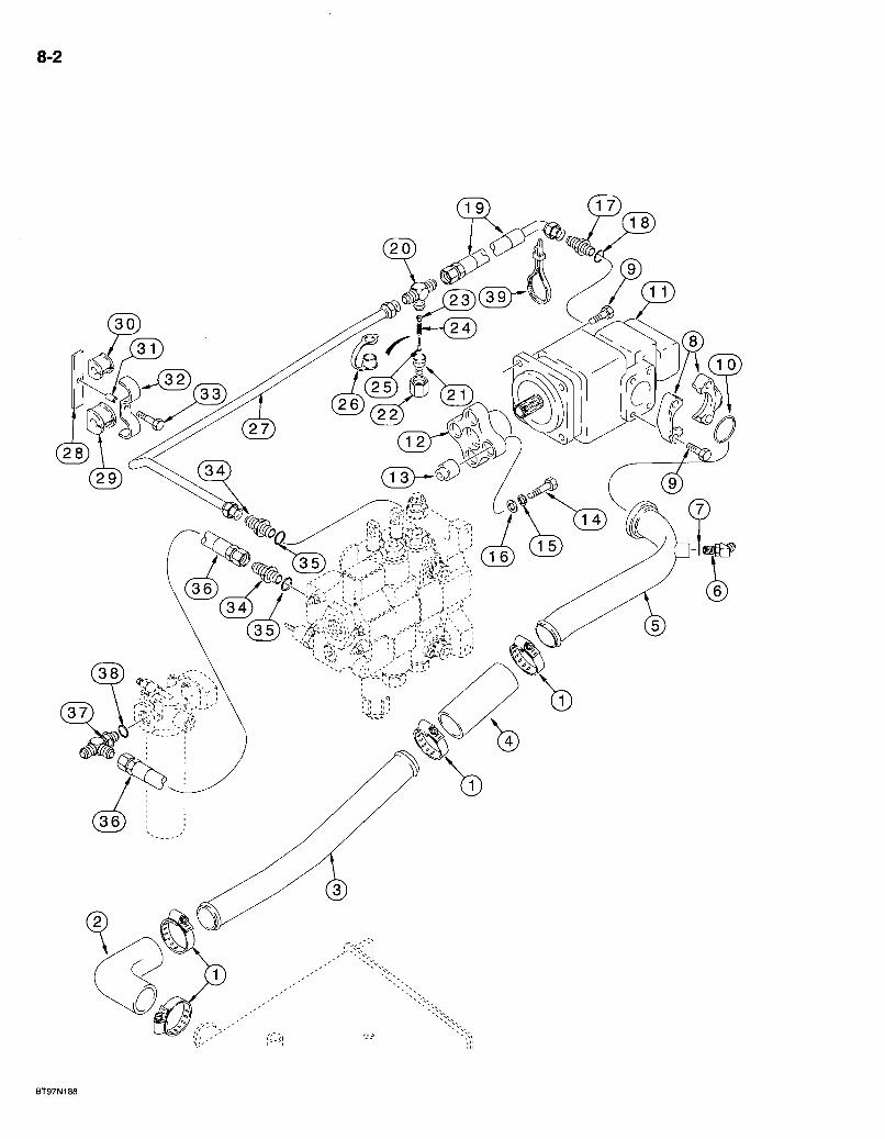
8-2
BT97N188
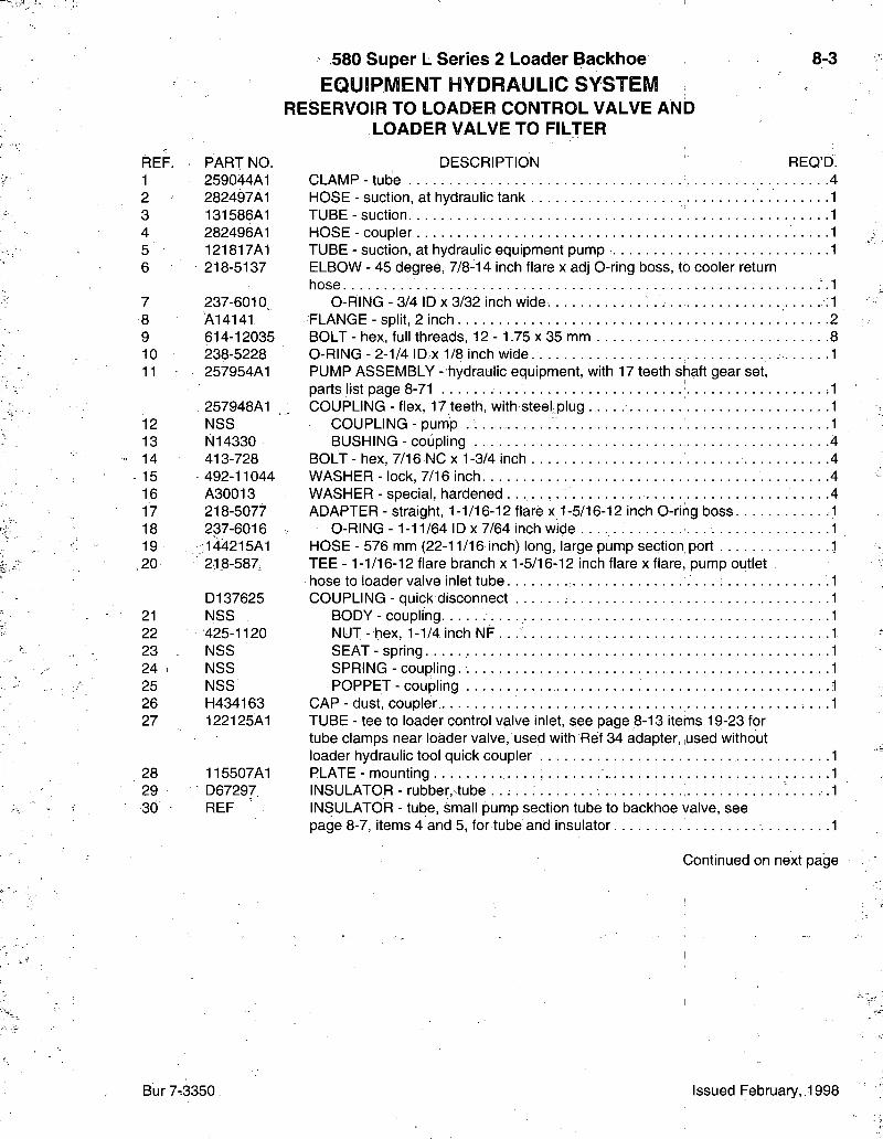
580 Super L Series 2 Loader Backhoe EQUIPMENT HYDRAULIC SYSTEM
RESERVOIR TO LOADER CONTROL VALVE AND LOADER VALVE TO FILTER
8-3
FIEF. PART NO. 1 259044A1 2 282497A1 3 . 131586A1 4 282496A1 5 121817A1 6 218-5137
7 237-6010. 8 A14141 9 614-12035 10 238-5228 11 257954A1
257948A1 12 NSS 13 N14330 14 413-728 15 492-11044 16 A30013 17 218-5077 18 237-6016 19 144215A1 20 r 21.8-587,
D137625 21 NSS 22 425-1120 23 NSS 24 NSS 25 NSS 26 H434163 27 122125A1
28 115507A1 29 D67297 30 REF
DESCRIPTION REQ'D. CLAMP-tube 4 HOSE - suction, at hydraulic tank 1 TUBE - suction 1 HOSE-coupler 1 TUBE - suction, at hydraulic equipment pump 1 ELBOW - 45 degree, 7/8-14 inch flare x adj 0-ring boss, to cooler return hose -1
0-RING - 3/4 ID X 3/32 inch wide. :1 FLANGE - split, 2 inch 2 BOLT - hex, full threads, 12 - 1.75 x 35 mm 8 0-RING - 2-1/4 ID X 1/8 inch wide. 1 PUMP ASSEMBLY - hydraulic equipment, with 17 teeth shaft gear set, parts list page 8-71 1 COUPLING - flex, 17 teeth, with steefplug 1
COUPLING - pump . 1 BUSHING - coupling 4
BOLT - hex, 7/16 NC x 1-3/4 inch 4 WASHER - lock, 7/16 inch 4 WASHER - special, hardened . . . . . . 4 ADAPTER - straight, 1-1/16-12 flare x 1-5/16-12 inch O-ring boss .1
O-RING- 1-11/64 ID X 7/64 inch wide 1 HOSE - 576 mm (22-11/16 inch) long, large pump section port .1 TEE -1-1/16-12 flare branch x 1-5/16-12 inch flare x flare, pump outlet hose to loader valve inlet tube .1 COUPLING - quick disconnect 1
BODY - coupling 1 NUT-hex, 1-1/4 inch N F . . . 1 SEAT - spring 1 SPRING - coupling. 1 POPPET - coupling 1
CAP - dust, coupler 1 TUBE - tee to loader control valve inlet, see page 8-13 items 19-23 for tube clamps near loader valve, used with Ref 34 adapter, used without loader hydraulic tool quick coupler . 1 PLATE - mounting .1 INSULATOR - rubber, tube .1 INSULATOR - tube, small pump section tube to backhoe valve, see page 8-7, items 4 and 5, for tube and insulator 1
Continued on next page
Bur 7.3350. Issued February, 1998

8-4
BT97N188
580 Super L Series 2 Loader Backhoe EQUIPMENT HYDRAULIC SYSTEM
RESERVOIR TO LOADER CONTROL VALVE AND LOADER VALVE TO FILTER
8-5
REF. 31 32 33 34
35 36
37
38 39
PART NO. R46493 D143422 814-10050 218-5069
237-6016 144227A1
218-5245
237-6016 LI 8337
DESCRIPTION REQ'D. SPACER - split, 22 mm (7/8 inch) long 1 CLAMP- double tube 1 BOLT-hex, 10- 1.5x50 mm 1 ADAPTER - straight, 1-5/16-12 inch flare x 0-ring boss, at loader valve inlet and outlet ports, adapter at upper port is replaced by a tee on models with loader hydraulic tool quick coupler, see page 8-65, Ref 10 2
O-RING -1-11/64 ID X 7/64 inch wide . 1 HOSE - 520 mm (20-15/32 inch) long, loader valve to filter, models without ride control, see page 8-61 for parts used on models with ride control 1 TEE -1-5/16-12 inch flare branch x flare x adj 0-ring boss, loader valve to filter and filter to backhoe control valve 1
0-RING -1 -11/64 ID X 7/64 inch wide 1 STRAP - tie, 15 inch, if used .1
Bur 7-3350 Issued February, 1998
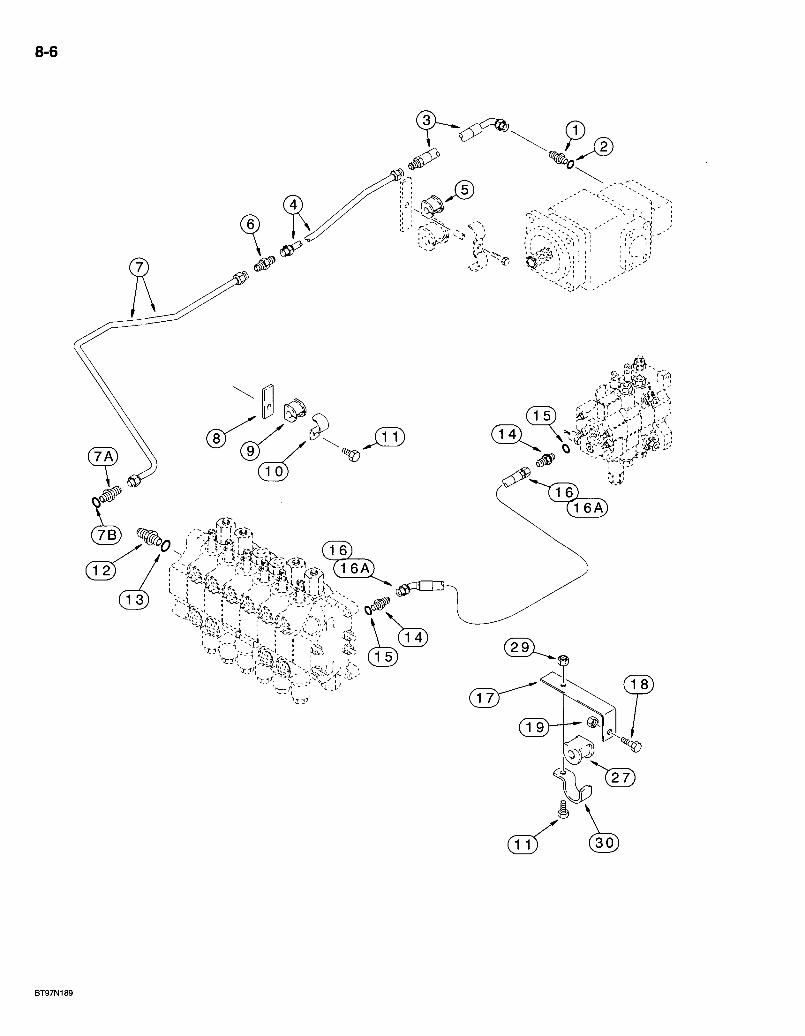
8-6
< : £ . > - ^ > W ^ r k ^ (i6A^
3 ^ A
580 Super L Series 2 Loader Backlioe EQUIPMENT HYDRAULIC SYSTEM
EQUIPIVIENT PUIVIP AND LOADER CONTROL VALVE TO BACKHOE CONTROL VALVE
8-7
REF. 1
2 3 4 5
6 7 7A 7B 8 9 10 11 12 13 14 15 16
16A
17 18 19 27 29 30
PART NO. 218-5063
237-6012 144216A1 122127A1 D143797
218-736 243790A1 218-5062 237-6010 115633A1 D143797 D143411 614-10025 218-5062 237-6010 218-5069 237-6016 144240A1
144241A1
136008A1 614-12030 829-1412 144477A1 829-1410 144479A1
DESCRIPTION ADAPTER - straight, 7/8-14 flare x 1-1/16-12 inch O-ring boss, small pump section outlet port
O-RING - 59/64 ID x 7/64 inch wide HOSE - 800 mm (31-1/2 inch) long, small pump section outlet p o r t . . . . TUBE - small pump section hose to backhoe INSULATOR - 5/8 inch, small pump section tube, see page 8-3 and 8-5 items 28 - 33 for hardware CONNECTOR - straight, 7/8-14 inch flare. TUBE - swing supply, small pump tube to swing section in|et ADAPTER - straight, 7/8-14 inch flare x O-ring boss.
O-RING - 3/4 ID X 3/32 inch wide. . PLATE - mounting INSULATOR - 5/8 inch, tube mounting CLAMP - P-type, 3/4 inch ID, tube
REQ'D.
BOLT - hex, full threads, 10 -1.5 x 25 mm , .2 ADAPTER - straight, 7/8-14 inch flare x O-ring boss.
O-RING - 3/4 ID X 3/32 inch wide ADAPTER - straight, 1-5/16-12 inch
O-RING - 1-11/64 ID X 7/64 inch flare X O-ring boss wide
HOSE - 1028 mm (40-1/2 inch) long, loader valve power beyond port to backhoe control valve inlet, models with two spool loader control valve.. HOSE - 977 mm (38-15/32 inch) long, loader valve power beyond port to backhoe control valve inlet, models with three spool loader control valve .1 BRACKET - mounting, hose 1 BOLT - hex, full threads, 12 - 1.75 x 30 mm 1 NUT - hex, 12 mm -1.75, class 10 .1 INSULATOR - rubber, power beyond hose.; 1 NUT - hex, 10 mm -1^5, class 10.9. 1 CLAMP - isolation, if used 1
Bur 7-3350 Issued February, 1998
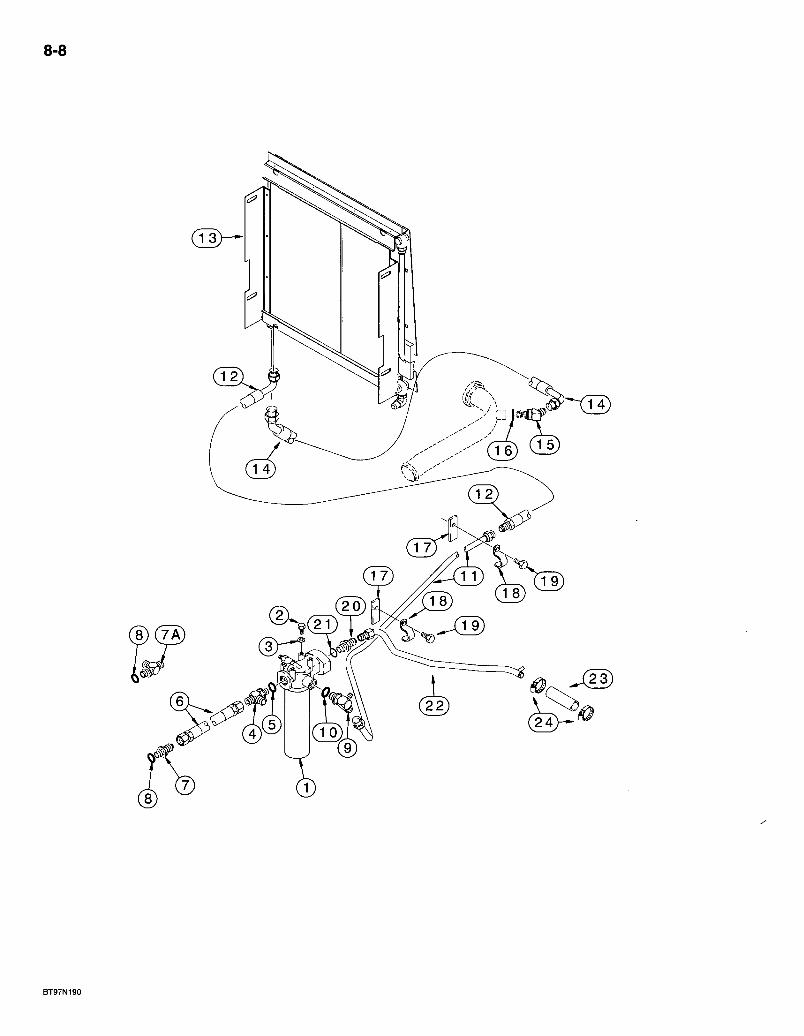
8-8
J23)
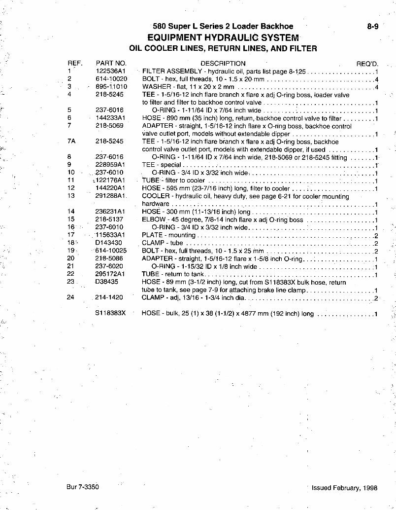
REF. PART NO. 1 122536A1 2 614-10020 3 . • 895-1,1010 4 218-5245
5 237-6016 6 144233A1 7 218-5069
7A 218-5245
8 237-6016 9 228959A1 10 237-6010 11 i,122176A1 12 144220A1 13 291288A1
14 236231A1 15 218-5137 16 237-6010 17 •115633A1 18- D143430 19 614-10025 20 218-5086 21 237-6020 22 295172A1 23 D38435
24 214-1420
S118383X
580 Super L Series 2 Loader Backhoe 8-9 EQUIPMENT HYDRAULie SYSTEM
OIL COOLER LINES, RETURN LINES, AND FILTER
DESCRIPTION REQ'D. FILTER ASSEMBLY - hydraulic oil, parts list page 8-125 1 BOLT - hex, full threads, 10 -1.5 x 20 mm 4 WASHER - flat, 11 x 20 x 2 mm .4 TEE -1-5/16-12 inch flare branch x flare x adj 0-ring boss, loader valve to filter and filter to backhoe control valve 1
0-RING -1-11/64 ID X 7/64 inch wide 1 HOSE - 890 mm (35 inch) long, return, backhoe control valve to filter 1 ADAPTER - straight, 1 -5/16-12 inch flare x O-ring boss, backhoe control valve outlet port, models without extendable dipper .1 TEE -1-5/16-12 inch flare branch x flare x adj 0-ring boss, backhoe control valve outlet port, models with extendable dipper, if used 1
O-RING - 1-11/64 ID X 7/64 inch wide, 218-5069 or 218-5245 fitting 1 TEE - special 1
0-RING - 3/4 ID X 3/32 inch wide 1 TUBE - filter to cooler 1 HOSE - 595 mm (23-7/16 inch) long, filter to cooler . . . . : 1 COOLER - hydraulic oil, heavy duty, see page 6-21 for cooler mounting hardware 1 HOSE - 300 mm (11-13/16 inch) long 1 ELBOW - 45 degree, 7/8-14 inch flare x adj 0-ring boss 1
O-RING - 3/4 ID x 3/32 inch wide 1 PLATE - mounting 2 CLAMP-tube 2 BOLT - hex, full threads, 10 -1.5 x 25 mm 2 ADAPTER - straight, 1-5/16-12 flare x 1-5/8 inch O-ring. 1
O-RING -1-15/32 ID x 1/8 inch wide .1 TUBE - return to tank 1 HOSE - 89 mm (3-1/2 inch) long, cut from SI 18383X bulk hose, return tube to tank, see page 7-9 for attaching brake line clamp 1 CLAMP - adj, 13/16 -1-3/4 inch dia .2
HOSE - bulk, 25(1) X 38 (1-1/2) X 4877 mm (192 inch) long 1
Bur 7-3350 Issued February, 1998
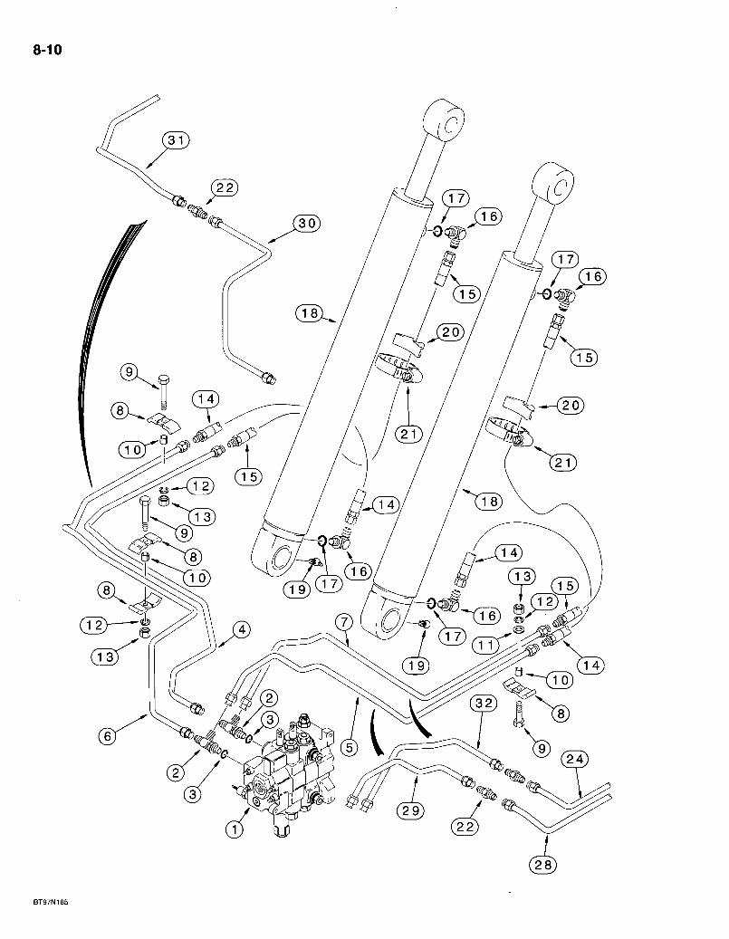
8-10
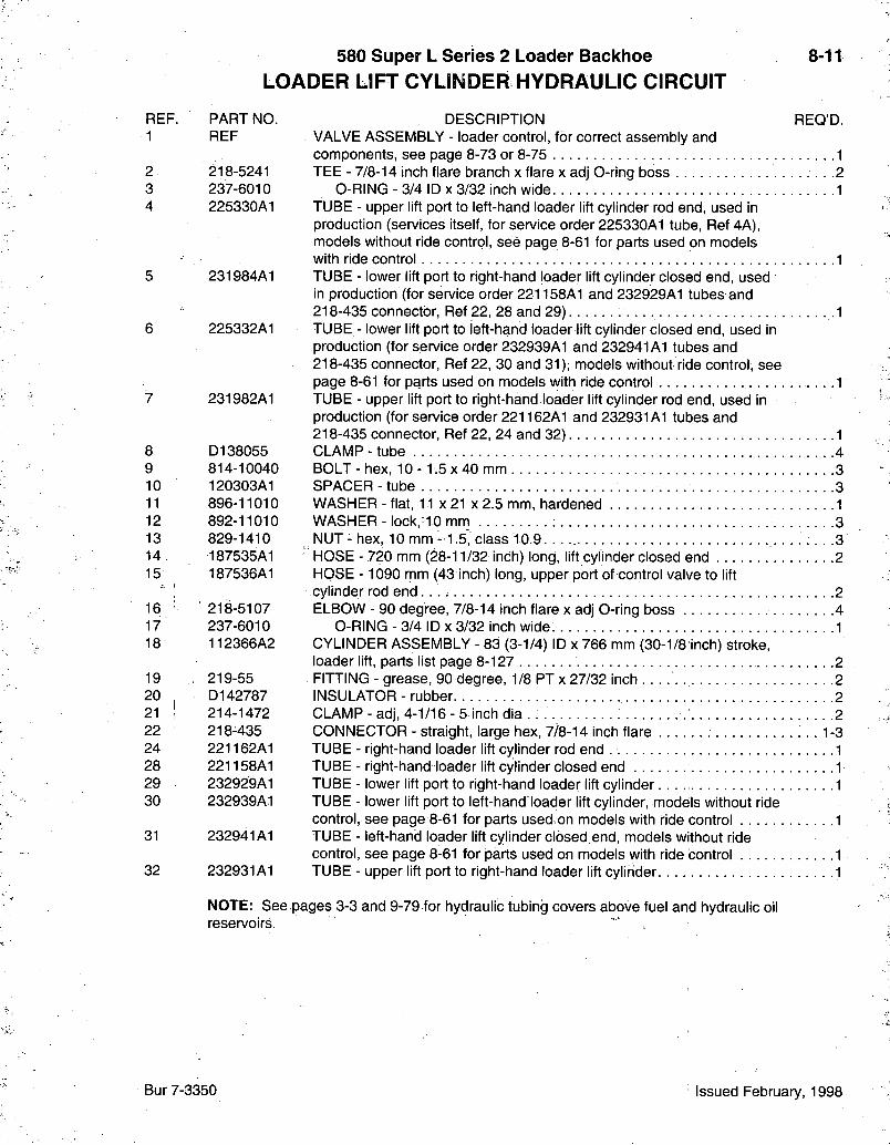
580 Super L Series 2 Loader Backhoe LOADER LIFT CYLINDER HYDRAULIC CIRCUIT
8-11
REF. PART NO 1 REF
2- 218-5241 3 237-6010 4 225330A1
5 231984A1
6 225332A1
7 231982A1
8 9 10 11 12 13 14 15
16 17 18
19 20 21 22 24 28 29 30
31
32
D138055 814-10040 120303A1 896-11010 892-11010 829-1410 187535A1 187536A1
218- 5107 237-6010 112366A2
219- 55 D142787 214-1472 218-435 221162A1 221158A1 232929A1 232939A1
232941A1
232931A1
DESCRIPTION REQ'D. VALVE ASSEMBLY - loader control, for correct assembly and components, see page 8-73 or 8-75 1 TEE - 7/8-14 inch flare branch x flare x adj O-ring boss . . .2
0-RING - 3/4 ID X 3/32 inch wide .1 TUBE - upper lift port to left-hand loader lift cylinder rod end, used in production (services; itself, for service order 225330A1 tube, Ref 4A), models without ride control, see page 8-61 for parts used on models with ride control 1 TUBE - lower lift port to right-hand loader lift cylinder closed end, used in production (for service order 221158A1 and 232929A1 tubes and 218-435 connector, Ref 22, 28 and 2 9 ) . . . . . . .1 TUBE - lower lift port to jeft-hand loader lift cylinder closed end, used in production (for service order 232939A1 and 232941A1 tubes and 218-435 connector, Ref 22, 30 and 31), models without ride control, see page 8-61 for parts used on models with ride control 1 TUBE - upper lift port to right-hand loader lift cylinder rod end, used in production (for service order 221162A1 and 232931A1 tubes and 218-435 connector, Ref 22, 24 and 32) 1 CLAMP-tube 4 BOLT-hex, 10- 1.5x40 mm 3 SPACER - tube 3 WASHER - flat, 11 x 21 x 2.5 mm, hardened 1 WASHER-lock, 10 mm 3 NUT - hex, 10 mm -1.5, class 10.9. . . . . . . . . . . .3
' HOSE - 720 mm (28-11/32 inch) long, lift cylinder closed end 2 HQSE - 1090 rrim (43 inch) long, upper port of control valve to lift cylinder rod end 2 ELBOW - 90 degree, 7/8-14 inch flare x adj O-ring boss 4
0-RlNG - 3/4 ID X 3/32 inch wide. 1 CYLINDER ASSEMBLY - 83 (3-1/4) ID x 766 mm (30-1/8 inch) stroke, loader lift, parts list page 8-127 2 FITTING - grease, 90 degree, 1/8 PT x 27/32 inch 2 INSULATOR - rubber 2 CLAMP - adj, 4-1/16 - 5 inch dia . . . . . 2 CONNECTOR - straight, large hex, 7/8-14 inch flare 1-3 TUBE - right-hand loader lift cylinder rod end 1 TUBE - right-hand loader lift cylinder closed end 1 TUBE - lower lift port to right-hand loader lift cylinder 1 TUBE - lower lift port to left-hand loader lift cylinder, models without ride control, see page 8-61 for parts used on models with ride control 1 TUBE - left-hand loader lift cylinder closed end, models without ride control, see page 8-61 for parts used on models with ride control 1 TUBE - upper lift port to right-hand loader lift cylinder 1
NOTE: See pages 3-3 and 9-79 for hydraulic tubing covers above fuel and hydraulic oil reservoirs.
Bur 7-3350 Issued February, 1998

8-12
BT97N186
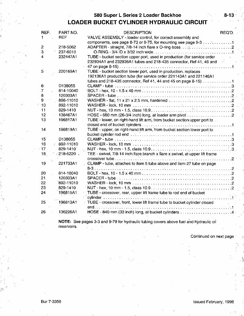
580 Super L Series 2 Loader Backhoe LOADER BUCKET CYLINDER HYDRAULIG CIRCUIT
8-13
REF. 1
2 3 4
6 7 8 9 10 11 12 13
14
15 16 17 18
19
20 21 22 23 24
25
26
PART NO. DESCRIPTION REQ'D. REF VALVE ASSEMBLY - loader control, for correct assembly and
components, see page 8-73 or 8-75, for mounting see page 9-3 1 218-5062 ADAPTER - straight, 7/8-14 inch flare x O-ring boss. . . .i 2 237-6010 O-RING - 3/4 ID x 3/32 inch wide 1 232447A1 TUBE - bucket section upper port, used in production (for service order
232934A1 and 232936A1 tubes and 218-435 connector, Ref 41 , 46 and 47 on page 8-15) 1
220169A1 TUBE - bucket section lower port, used in production, replaces 192136A1 production tube (for service order 221143A1 and221146A1 tubes and 218-435 connector, Ref 4 1 , 44 and 45 on page 8-15) 1
D138055 CLAMP - tube 3 814-10040 BOLT-hex , 1 0 - 1 . 5 x 4 0 mm 2 120303A1 SPACER - tube . .2 896-11010 WASHER - flat, 1 1 x 2 1 x 2 . 5 mm, hardened .2 892-11010 . WASHER- lock, 10 mm . . . . . . .2 829-1410 NUT - hex, 10 mm - 1.5, class 10.9 .2 138467A1 HOSE - 680 mm (26-3/4 inch) long, at loader arm pivot 2 196817A1 TUBE - lower, on right-hand lift arm, from bucket section upper port to
closed end of bucket cyinders 1 196819A1 TUBE - upper, on right-hand lift arm, frorn bucket section lower port to
bucket cyinder rod end . 1 D138055 CLAMP - tube . 3 892-11010 WASHER- lock, 10 mm 3 829-1410 , NUT - hex, 10 mm -1 .5 , class 10:9. .3 218-5220 * TEE - swivel, 7/8-14 inch flare; branch x flare x swivel, at upper lift frame
crossover tube 2 221733A1 , CLAMP - tube, attaches to item 5 tube above and item 27 tube on page
8-3 2 814-10040 BOLT-hex , 1 0 - 1 . 5 x 4 0 mm 2 120303A1 SPACER - tube 2 892-11010 WASHER- lock, 10 mm . . 2 829-1410 NUT-hex , 10 mm - 1.5, class 10:9 .2 196815A1 TUBE - crossover, rear, upper lift frame tube to rod end of bucket
cylinder .1 196813A1 TUBE - crossover, front, lower lift frame tube to bucket cylinder closed
end .1 136226A1 HOSE - 840 mm (33.inch) long, at bucket cylinders .4
NOTE: See pages 3-3 and 9-79 for hydraulic tubing covers above fuel and hydraulic oil resen/oirs.
Continued on next page
Bur 7-3350 Issued February, 1998
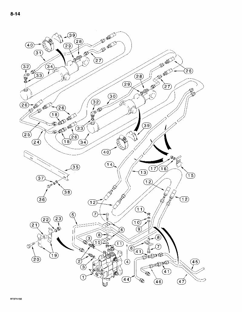
8-14
( 2 2 ) ( 2 3 )
BT97N186
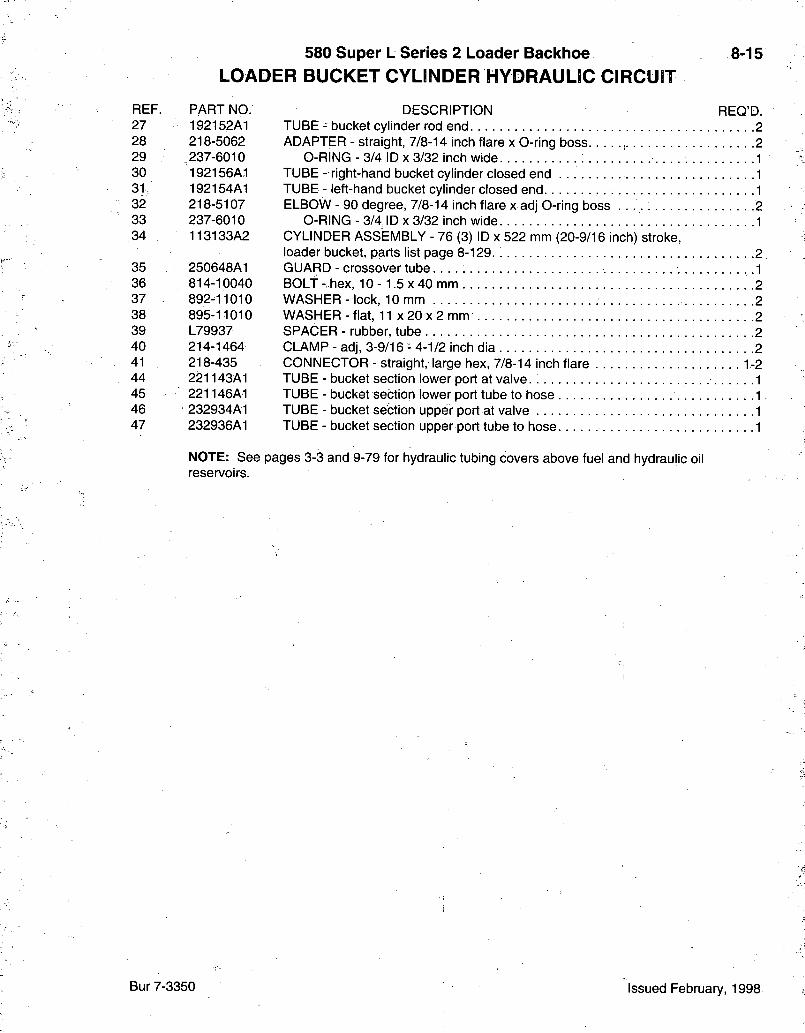
580 Super L Series 2 Loader Backhoe LOADER BUCKET CYLINDER HYDRAULIC CIRCUIT
8-15
REF. PART NO. DESCRIPTION REQ'D. 27 192152A1 TUBE - bucket cylinder rod end 2 28 218-5062 ADAPTER - straight, 7/8-14 inch flare x O-ring boss 2 29 237-6010 O-RING - 3/4 ID x 3/32 inch wide 1 30 192156A1 TUBE - right-hand bucket cylinder closed end 1 3 1 / 192154A1 TUBE - left-hand bucket cylinder closed end 1 32 218-5107 ELBOW - 90 degree, 7/8-14 inch flare x adj O-ring boss 2 33 237-6010 O-RING - 3/4 ID x 3/32 inch wide 1 34 113133A2 CYLINDER ASSEMBLY - 76 (3) ID x 522 mm (20-9/16 inch) stroke,
loader bucket, parts list page 8-129 2 . 35 250648A1 GUARD - crossover tube .1 36 814-10040 BOLT- hex, 1 0 - 1 . 5 x 4 0 mm 2 37 892-11010 WASHER- lock, 10 mm 2 38 895-11010 WASHER - flat, 11 X 20 X 2 mm 2 39 L79937 SPACER - rubber, tube 2 .40 214-1464 CLAMP-ad j , 3-9/16-4-1/2 inch dia 2 41 218-435 CONNECTOR - straight, large hex, 7/8-14 inch flare 1-2 44 221143A1 TUBE - bucket section lower port at valve. 1 45 221146A1 TUBE - bucket section lower port tube to hose 1 46 232934A1 TUBE - bucket section upper port at valve .1 47 232936A1 TUBE - bucket section upper port tube to hose 1
NOTE: See pages 3-3 and 9-79 for hydraulic tubing covers above fuel and hydraulic oil reservoirs.
Bur 7-3350 Issued February, 1998
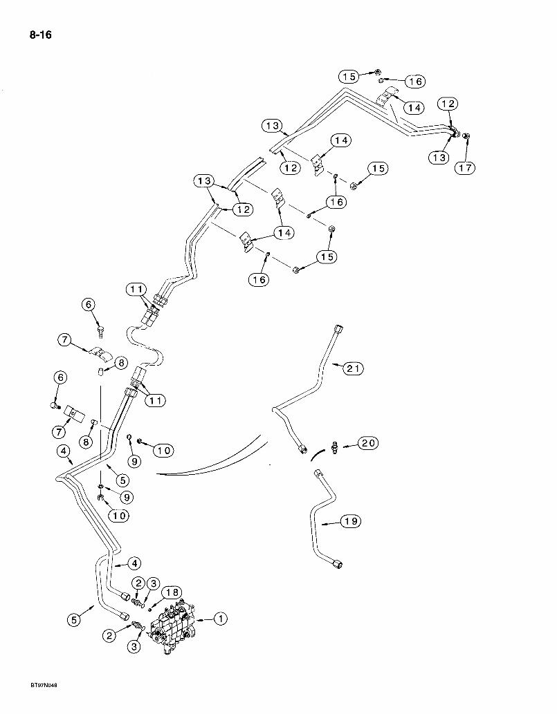
8-16
BT97N048
580 Super L Series 2 Loader Backhoe LOADER GLAM CYLINDER HYDRAULIC CIRCUIT
8-17
REF. 1
2 3 4
6 7 8 9 10 11 12 13 14 i s ; 16 17
18 19 20 21
PART NO. 302966A1
218-5062 237-6010 225326A1
225328A1
814-10040 D138055 120303A1 892-11010 829-1410 138467A1 196824A1 196821A1 D138055 829-1410 892-11010 218-776
188058A1 232945A1 218-435 232947A1
DESCRIPTION REQ'D. VALVE ASSEMBLY - loader control, three-spool, parts list page 8-75, for mounting hardware see page 9-3 1 ADAPTER - straight, 7/8-14 inch flare x O-ring boss 2
O-RING - 3/4 ID X 3/32 inch wide .1 TUBE - upper port loader valve clam section to hose at loader arm pivot (services itself). 1 TUBE - lower port loader valve clam sectiorfto hose at loader arm pivot, used in production (for service order 232945A1 and 232947A1 tubes and 218-435 connector, Ref 19-21) 1 BOLT - hex, 10 -1 .5 x 40 mm, mm 2 CLAMP-tube. : -2 SPACER-tube 2 WASHER - lock, 10 mm . . . . ! .2 NUT - hex, 10 mm -1 .5 , class 10.9. 2 HOSE - 680 mm (26-3/4 inch) long, at loader arm pivot 2 TUBE - lower, on loader lift frame, port A 1 TUBE - upper, on loader lift frame, port B 1 CLAMP - tube 4 NUT - hex, 10 mm -1 .5 , class 10.9 4 WASHER - lock, 10 mm . . . . 4 PLUG - hex, 7/8-14 inch flare, not used on models with clam bucket, if used ' - 2 RESTRICTOR - check 1 TUBE - lower port at loader valve 1 CONNECTOR - straight, large hex, 7/8-14 inch flare 1 TUBE - lower port at loader valve 1
NOTE: See pages 3-3 and 9-79 for hydraulic tubing-covers above fuel and hydraulic oil reservoirs.
Bur 7-3350 Issued February, 1998
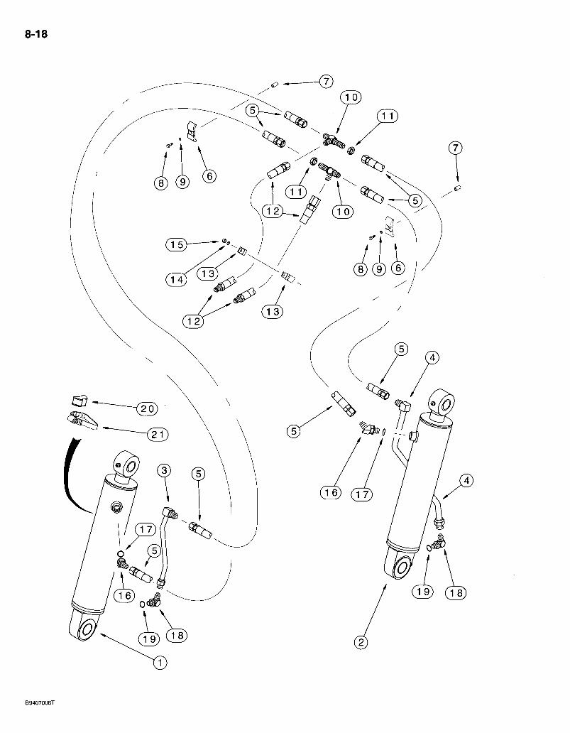
8-18
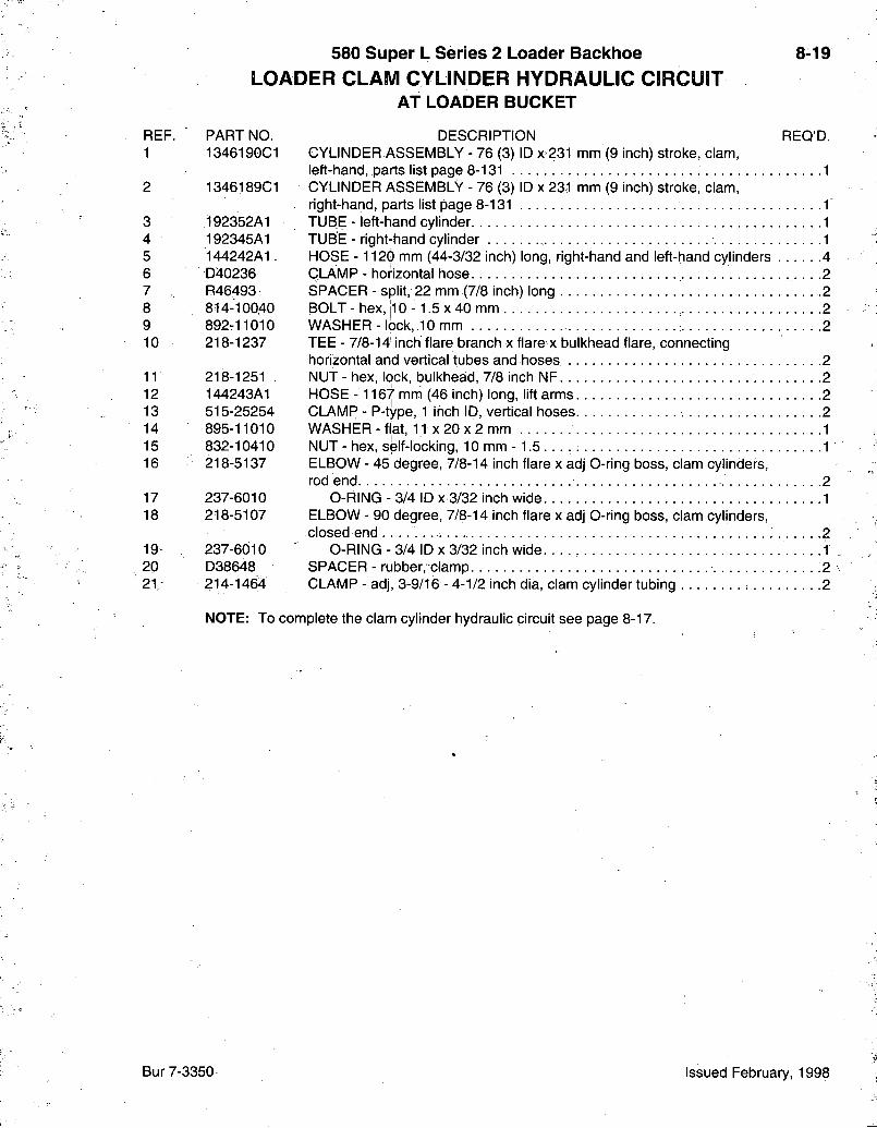
580 Super L Series 2 Loader Backhoe LOADER CLAM CYLINDER HYDRAULIC CIRCUIT
AT LOADER BUCKET
8-19
REF. 1
3 4 5 6 7 8 9 10
11 12 13 14 15 16
17 18
19 20 2 1 /
PART NO. DESCRIPTION REQ'D. 1346190C1 CYLINDER ASSEMBLY - 76 (3) ID x=231 mm (9 inch) stroke, clam,
left-hand, parts list page 8-131 1 1346189C1 CYLINDER ASSEMBLY - 76 (3) ID x 231 mm (9 inch) stroke, clam,
right-hand, parts list page 8-131 1 192352A1 TUBE - left-hand cylinder 1 192345A1 TUBE - rightjhand cylinder 1 144242A1. HOSE -1120 mm (44-3/32 inch) long, right-hand and left-hand cylinders 4 D40236 CLAMP - horizontal hose 2 R46493 SPACER - split, 22 mm (7/8 inch) long 2 814-10040 BOLT - hex, jl 0 -1 .5 x 40 mm 2 892r11010 WASHER - lock, .10 mm 2 218-1237 TEE - 7/8-14] inch flare branch x flare x bulkhead flare, connecting
horizontal and vertical tubes and hoses 2 218-1251 NUT - hex, lock, bulkhead, 7/8 inch NF 2 144243A1 HOSE -1167 mm (46 inch) long, lift arms 2 515-25254 CLAMP - P-type, 1 inch ID, vertical hoses 2 895-11010 WASHER - flat, 11 x 20 x 2 mm 1 832-10410 NUT - hex, self-locking, 10 mm -1 .5 1 218-5137 ELBOW - 45 degree, 7/8-14 inch flare x adj 0-ring boss, clam cylinders,
rod end 2 237-6010 O-RING - 3/4 ID x 3/32 inch wide 1 218-5107 ELBOW - 90 degree, 7/8-14 inch flare x adj O-ring boss, clam cylinders,
closed end 2 237-6010 O-RING - 3/4 ID x 3/32 inch wide 1 D38648 SPACER - rubber, clamp .2 214-1464 CLAMP - adj, 3-9/16 - 4-1/2 inch dia, clam cylinder tubing 2
NOTE: To complete the clam cylinder hydraulic circuit see page 8-17.
Bur 7-3350 Issued February, 1998

8-20
r X 2 l ) (201
( 3 5 ) ( 3 6 ( 2 7 ) ^
BT97N182
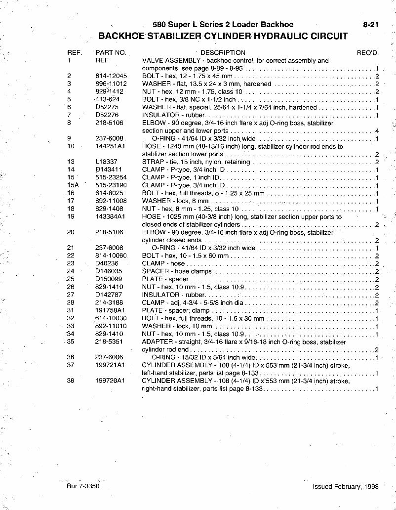
580 Super L Series 2 Loader Backhoe BACKHOESTABILIZER CYLINDER HYDRAULIC CIRCUIT
8-21
REF. PART NO. 1 REF
2 814-12045 3 896-1.1012 4 829^1412 5 413-624 6 D52275 7 D52276 8 218-5106
9 237-6008 10 144251A1
13 L18337 14 D143411 15 515-23254 15A 515-23190 16 614-8025 17 892-11008 18 829-1408 19 143384A1
20 218-5106
21 237-6008 22 814-10060 23 D40236 24 D146035 25 D150099 26 829-1410 27 D142787 28 214-3188 31 191758A1 32 614-10030 33 '892-11010 34 829-1410 35 218-5351
36 237-6006 37 199721A1
38 199720A1
DESCRIPTION REQ'D. VALVE ASSEMBLY - backhoe control, for correct assembly and components, see page 8-89 - 8-95 1 BOLT - hex, 12 - 1.75 x 45 mm 2 WASHER - flat, 13.5 x 24 x 3 mm, hardened 2 NUT-hex , 12 mm-1 .75 , class 10 .2 BOLT - hex, 3/8 NC x 1-1/2 inch 1 WASHER - flat, special, 25/64 x 1-1/4 x 7/64 inch, hardened 1 INSULATOR - rubber 1 ELBOW - 90 degree, 3/4-16 inch flare x adj O-ring boss, stabilizer section upper and lower ports 4
O-RING - 41/64 ID x 3/32 inch wide .1 HOSE - 1240 mm (48-13/16 inch) long, stabilizer cylinder rod ends to stablizer section lower ports 2 STRAP - tie, 15 inch, nylon, retaining 2 CLAMP - P-type, 3/4 inch ID . . . . .1 CLAMP - P-type, 1 inch ID 1 CLAMP - P-type, 3/4 inch ID .1 BOLT - hex, full threads, 8 - 1.25 x 25 mm 1 WASHER - lock, 8 mm , 1 NUT - hex, 8 mm -1.25, class 10 1 HOSE - 1025 mm (40-3/8 inch) long, stabilizer section upper ports to closed ends of stabilizer cylinders 2 ELBOW - 90 degree,,3/4-16 inch flare x adj O-ring boss, stabilizer cylinder closed ends 2
O-RING - 41/64 ID x 3/32 inch wide 1 BOLT - hex, 10 -1 .5 x 60 mm 2 CLAMP - hose .....2 SPACER - hose clamps. 2 PLATE-spacer 2 NUT-hex , 10 m m - 1.5, class 10.9 2 INSULATOR - rubber 2 CLAMP - adj, 4-3/4 - 5-5/8 inch dia . 2 PLATE - spacer, clamp 1 BOLT - hex, full threads, 10 -1 .5 x 30 mm .1 WASHER - lock, 10 mm 1 NUT-hex , 10 m m - 1 . 5 , class 10.9 1 ADAPTER - straight, 3/4-16 flare x 9/16-18 inch O-ring boss, stabilizer cylinder rod end 2
O-RING - 15/32 ID X 5/64 inch wide 1 CYLINDER ASSEMBLY -108 (4-1/4) ID x 553 mm (21-3/4 inch) stroke, left-hand stabilizer, parts list page 8-133 1 CYLINDER ASSEMBLY -108 (4-1/4) ID x 553 mm (21-3/4 inch) stroke, right-hand stabilizer, parts list page 8 - 1 3 3 . . . . 1
Bur 7-3350 Issued February, 1998
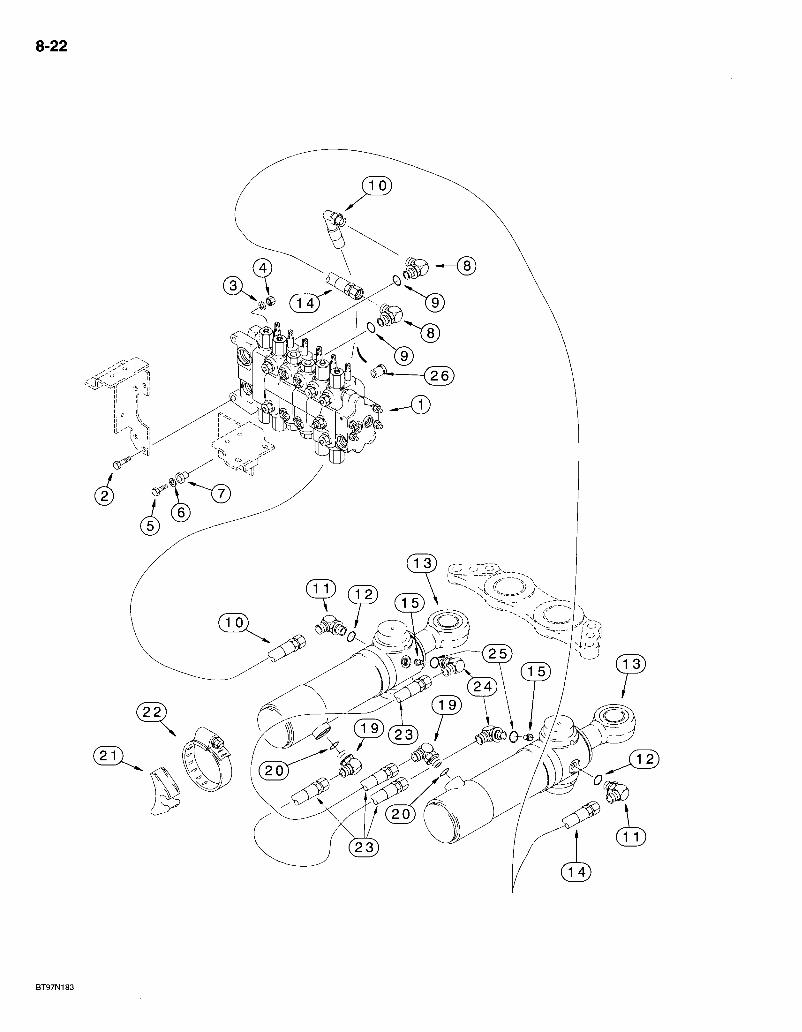
8-22
BT97N183
580 Super L Series 2 Loader Backhoe BACKHOE SWING CYLINDER HYDRAULIC CIRCUIT
8-23
REF. PART NO. 1 REF
2 814-12045 3 896-11012 4 829-1412 5 413-624 6 D52275 7 D52276 8 218-5119
9 237-6012 10 196278A1
11 218-5106
12 237-6008 13 REF
14 183243A1
15 124690A1 19 218-5119 20 237-6012 21 D142787 22 214-1488 23 255659A1
24 218-5106 25 237-6008 26 182222A1
DESCRIPTION REQ'D. VALVE ASSEMBLY - backhoe control, for correct assemb)ly and components, see page 8-89 - 8-95 1 BOLT - hex, 12 - 1.75 x 45 mm 2 WASHER - flat,,13.5 x 24 x 3 mm, hardened s2 NUT - hex, 12 mm - 1.75, class 10 2 BOLT - hex, 3/8 NC x 1-1/2 inch 1 WASHER - flat, special, 25/64 x 1-1/4 x 7/64 inch, hardened 1 INSULATOR - rubber 1 ELBOW - 90 degree, 7/8-14 flare x 1-1/16-12 inch adj O-ring boss, swing section upper and lower ports 2
O-RING - 59/64 ID x 7/64 inch wide 1 HOSE - 700 mm (27-9/16 inch) long, includes hose guard, swing section upper port to outer rod end of left-hand swing cylinder .1 ELBOW - 90 degree, 3/4-16 inch flare x adj O-ring boss, outer rod end of swing cylinders 2
O-RING - 41/64 ID X 3/32 inch wide 1 CYLINDER ASSEMBLY-102 (4) ID X 292 mm (11-1/2 inch) stroke, swing, parts list page 8-135... -2^ HOSE - 1400 mm (55-1/8 inch) long, right-hand swing cylinder outer rod end to swing section lower port 1 RESTRICTOR - check, 1/2 inch tube 2 ELBOW - 90 degree, 7/8-14 flare x 1-1/16-12 inch adj O-ring boss 2
O-RING - 59/64 ID x 7/64 inch wide .1 INSULATOR - rubber. . 2 CLAMP - adj, 5-1/8 - 6 inch dia 2 HOSE - 815 mm (32-3/32 inch) long, 1/2 inch ID, includes hose guard, crossover. -2 ELBOW - 90 degree, 3/4-16 inch flare x adj O-ring boss 2
O-RING - 41/64 ID x 3/32 inch wide 1 RESTRICTOR - check, 4.36 mm orifice, upper and lower ports 2
Bur 7-3350 Issued February, 1998
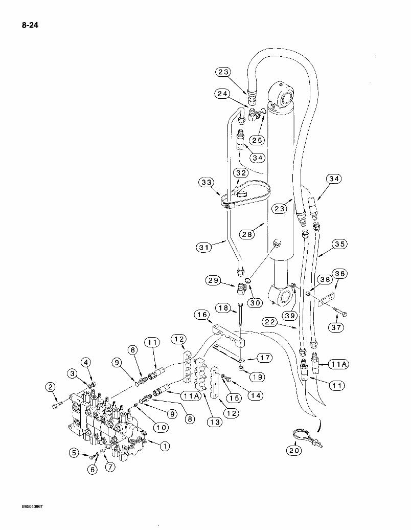
8-24
580 Super L Series 2 Loader Bacldioe *BACKHOE BOOM CYLINDER HYDRAULIC CIRCUIT
8-25
REF. PART NO: 1 REF
2 814-12045 3 896-11012 4 829-1412 5 413-624 6 D52275 7 D52276 8 218-5064
9 237-6012 10 D77182
11 193499A1
11A 193117A1
12 143439A1 13 176226A1 14 614-8025 15 892=11008 16 i43882A1 17 1322'12A1 18 814-12100 19 832-10412 20 LI 8337 22 142120A1 23 187845A1
24 218-5108
25 237-6012 28 144200A1
29 218-5123
30 237-6010 31 142815A1 32 D142787 33 214-14104 34 177634A1 35. 142122A1 36 133605A1 37 814-12080 38 132930A1 39 832-10412
DESCRIPTION REQ'D. VALVE ASSEMBLY - backhoe control, for correct assembly and components, see page 8-89 - 8-95 .1 BOLT - hex, 12 - 1.75 x 45 mm 2 WASHER - flat, 13.5 x 24 x 3 mm, hardened 2 NUT - hex, 12 mm -1.75, class 10 2 BOLT - hex, 3/8 NC x 1-1/2 inch WASHER - flat, special, 25/64 x 1-1/4 x 7/64 inch, hardened INSULATOR - rubber. ADAPTER - straight, 1.-1/16-12 inch flare x O-ring boss, boom section upper and lower ports
O-RING - 59/64 ID x 7/64 inch wide RESTRICTOR - check, boom section lower port, remove restrictor if equipped with boom lock valve circuit HOSE - 1295 mm (51 inch) long, includes hose guard and clamp, upper port control valve through swing tower to boom HOSE - 1295 mm (51 inch) long, includes hose guard and clamp, lower port control valve through swing tower to boom . . . CLAMP - hose, outer CLAMP - hose, center BOLT - hex, full threads, 8 - 1.25 x 25 mm WASHER - lock, 8 mm CLAMP - hose, at swing tower PLATE - hose clamp, at swing tower BOLT - hex, 12 - 1.75 x 100 mm NUT - hex, self-locking, 12 mm -1.75 STRAP - tie, 15 inch, nylon, retaining TUBE - to boom cylinder closed end hose HOSE - 1000 mm (39-3/8 inch) long, includes sleeve and banded clamps, boom cylinder closed end! ELBOW - 90 degree, 1-1/16-12 inch flare x adj O-ring boss, boom cylinder closed end, for models with boom lock valve, see page 8-59
O-RING - 59/64 ID x 7/64 inch wide CYLINDER ASSEMBLY - 127 (5) ID x 842 mm (33-5/32 inch) stroke, boom, parts list page 8-137 f. ELBOW - 90 degree, 1-1/16-12 flare x 7/8-14 inch adj O-ring boss, boom cylinder rod end
O-RING - 3/4 ID X 3/32 inch wide. TUBE - boom cylinder rod end INSULATOR - rubber CLAMP - adj, 6-1/8 - 7 inch dia, tube to cylinder HOSE - 440 mm (17-3/8 inch) long, to boom cylinder rod end tube TUBE - to boom cylinder rod end hose .
. CLAMP - boom cylinder tubes to inner left-hand side of boom 2 BOLT - hex, 1 2 - 1 .75x80 mm . . . . 4 SPACER-spl i t 4 NUT - hex, self-locking, 12 mm -1.75 4
'NOTE: See pages 8-57 and 8-59 for boom lock hydraulic and electrical circuit.
Bur 7-3350 Issued February, 1998
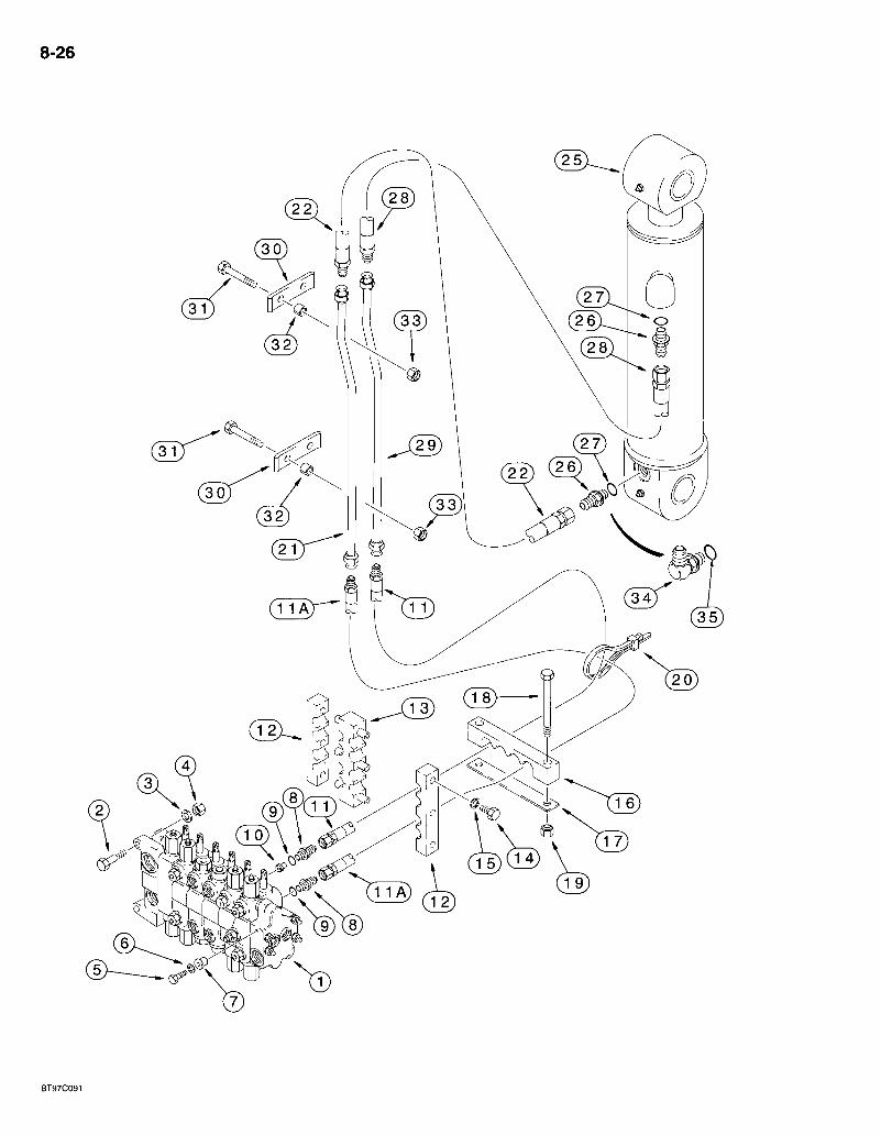
8-26
13) CiD
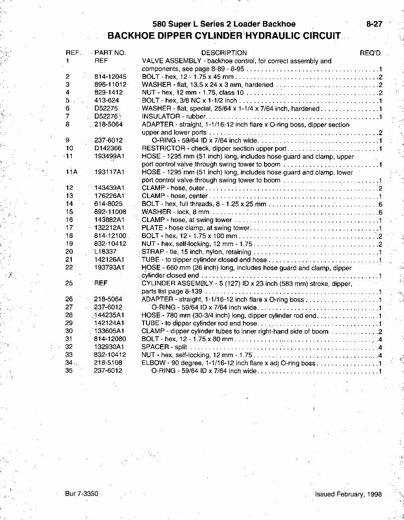
580 Super L Series 2 Loader Backhoe BACKHOE DIPPER CYLINDER HYDRAULIC CIRCUIT
8-27
REF. PART NO. 1 REF
2 814-12045 3 896-11012 4 829-1412 5 . 413-624 6 D52275 7 : D52276> 8 . 2i;8-5064
9 237-6012 10 D142366 11 193499A1
11A 193117A1
12 143439A1 13 176226A1 14 614-8025 15 892-11008 16 143882A1 17 132212A1 18 814-12100 19 832-10412 20 LI 8337 21 142126A1 22 193793A1
25 REF
26 218-5064 27 237-6012 28 ,144235A1 29 142124A1 30 133605A1 31 814-12080 32 132930A1 33 832-10412 34 . . 218-5108 35 237-6012
DESCRIPTION REQ'D. VALVE ASSEMBLY - backhoe control, for correct assembly and components, see page 8-89 - 8-95 1 BOLT - hex, 1 2 - 1.75 x 4 5 mm 2 WASHER - flat, 13.5 x 24 x 3 mm, hardened 2 NUT - hex, 12 mm -1.75, class 10 2 BOLT - hex, 3/8 NC x 1-1/2 inch 1 WASHER - flat, special, 25/64 x 1-1/4 x 7/64 inch, hardened 1 INSULATOR - rubber 1 ADAPTER - straight, 1-1/16-12 inch flare x O-ring boss, dipper section upper and lower ports 2
O-RING - 59/64 ID x 7/64 inch wide 1 RESTRICTOR - check, dipper section upper port 1 HOSE - 1295 mm (51 inch) long, includes hose guard and clamp, upper port control yalve through swing tower to boom 1 HOSE - 1295 mm (51 inch) long, includes hose guard and clamp, lower port control valve through swing tower to boom .1 CLAMP - hose, outer 2 CLAMP - hose, center 1 BOLT - hex, full threads, 8 - 1.25 x 25 mm 6 WASHER - lock, 8 mm 6 CLAMP - hose, at swing tower 1 PLATE - hose clamp, at swing tower 1 BOLT - hex, 12 - 1.75 x 100 mm 2 NUT - hex, self-locking, 12 mm - 1.75 2
; STRAP - tie, 15 inch, nylon, retaining 1 TUBE - to dipper cylinder closed end hose . . 1 HOSE - 660 mm (26 inch) long, includes hose guard and clamp, dipper cylinder closed end 1 CYLINDER ASSEMBLY - 5 (127) ID X 23 inch (583 mm) stroke, dipper, parts list page 8-139 1 ADAPTER - straight, 1-1/16-12 inch flare x O-ring boss .1
O-RING - 59/64 ID x 7/64 inch wide. 1 HOSE - 780 mm (30-3/4 inch) long, dipper cylinder rod end .1 TUBE - to dipper cylinder rod end hose. 1 CLAMP - dipper cylinder tubes to inner right-hand side of boom 2 BOLT - hex, 12 - 1.75 x 80 mm .4 SPACER-spl i t 4 NUT-hex , self-locking, 12 mm-.1.75 .4 ELBOW - 90 degree, 1-1/16-12 inch flare x adj O-ring boss 1
O-RING - 59/64 ID x 7/64 inch wide 1
Bur 7-3350 Issued February, 1998
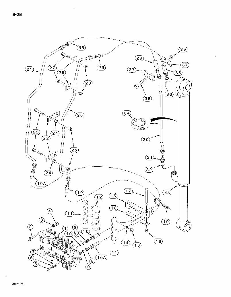
8-28
BT97N180

580 Super L Series 2 Loader Backhoe B A C K H O E B U C K E T C Y L I N D E R H Y D R A U L I C C I R C U I T
MODELS WITHOUT EXTENDABLE DIPPER
8 29
REF. PART NO. 1 REF
2 814-12045 3 896-11012 4 829-1412 5 413-624 6 D52275 , 7 D52276 8 218-5064
9 237-6012 10 193499A1
10A 193117A1
11 143439A1 12 176226A1 13 614-8025 14 892-11008 15 143882A1 16 132.212A1 1-7 814-12100 18 832-10412 19 L18337 20 141806A1 21 141801A1 22 133605A1 23 814-12080 24 132930A1 25 832-10412 26 133604A1 27 814-12060 28 832-10412 29 183660A1
30 256091A1 31 218-5064
32 237-6012
DESCRIPTION REQ'D. VALVE ASSEMBLY - backhoe control, for correct assembly and components, see page 8-89 or 8-91 1 BOLT - hex, 12 - 1.75 x 45 mm 2 WASHER - flat, 13.5 x 24 x 3 mm, hardened 2 NUT - hex, 12 mm - 1.75, class 10 2 BOLT - hex, 3/8 NC x 1-1/2 inch 1 WASHER - flat, special, 25/64 x 1-1/4 x 7/64 inch, hardened 1 INSULATOR - rubber 1 ADAPTER - straight, 1-1/16-12 inch flare x O-ring boss, bucket section upper and lower ports 2
O-RING - 59/64 ID x 7/64 inch wide . .1 HOSE - 1295 mm (51 inch) long, includes hose guard and clamp, upper port control valve through swing tower to boom .1 HOSE - 1295 mm (51 inch) long, includes hose guard and clamp, lower port control valve through swing tower to boom 1 CLAMP - hose, outer 2 CLAMP - hose, center .1 BOLT - hex, full threads, 8 - 1.25 x 25 mm .6 WASHER - lock, 8 mm 6 CLAMP - hose, at swing tower 1 PLATE - hose clamp, at swing tower 1 BOLT - hex, 12 - 1.75 x 100 mm 2 NUT - hex, self-locking; 12 mm -1.75 2 STRAP - tie, 15 inch, nylon, retaining 1 TUBE - right-hand side of boom, to bucket cylinder rod end 1 TUBE - left-hand side of boom, to bucket cylinder closed end 1 CLAMP - bucket cylinder tubes to inner sides of boom. 4 BOLT - hex, 1 2 - 1.75 x 80 mm 8 SPACER - split 8 NUT-hex , self-locking, 12 m m - 1 . 7 5 8 CLAMP - tube to boom 4 BOLT - hex, 12 - 1 .75x60 mm 4 NUT - hex, self-locking, 12 mm -1.75 4 HOSE - 640 mm (25-3/16 inch) long, includes hose guard and clamp, right-hand bucket tube on boom to bucket cylinder rod end tube 1 TUBE - bucket cylinder rod end 1 ADAPTER - straight, 1-1/16-12 inch flare x O-ring boss, bucket cylinder rod end 1
O-RING - 59/64 ID x 7/64 inch wide 1
Continued on next page
Bur 7-3350 Issued February, 1998
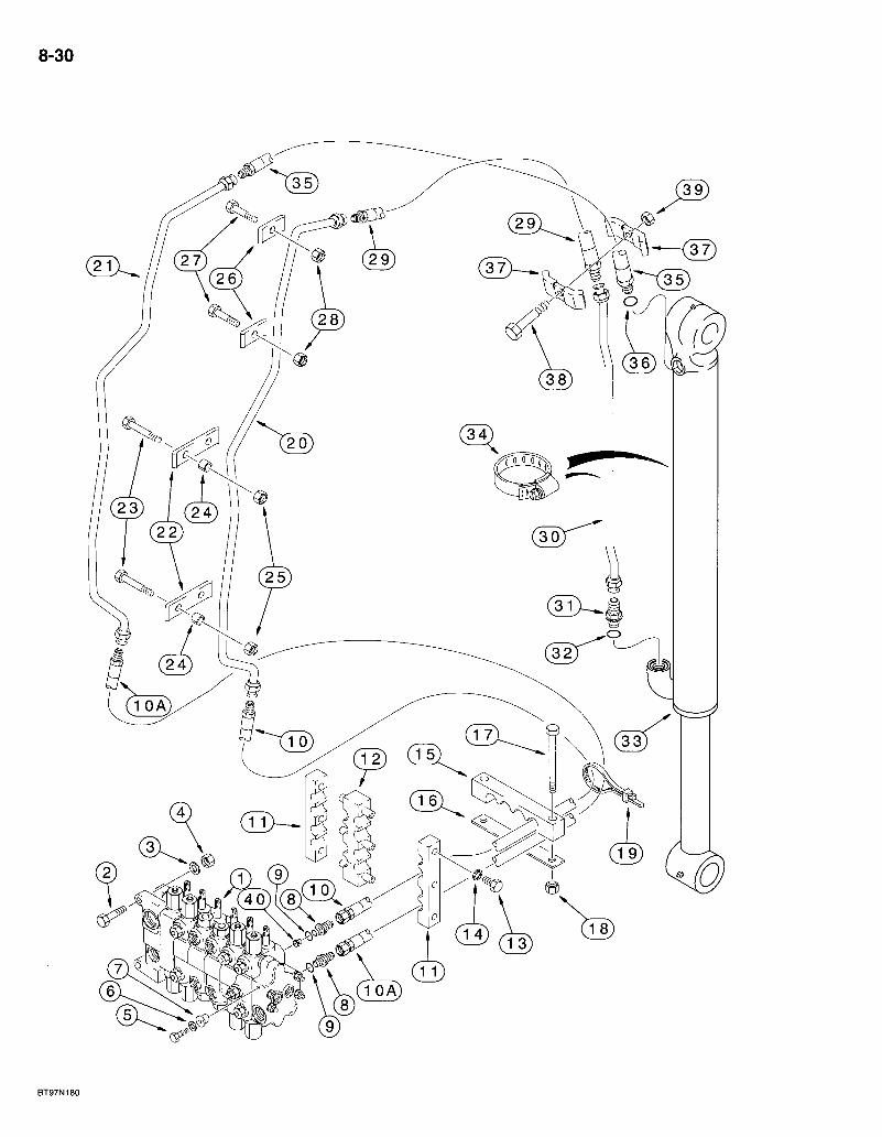
8-30
BT97N180
580 Super L Series 2 Loader Backhoe B A G K H O E B U C K E T C Y L I N D E R H Y D R A U L I C C I R C U I T
MODELS WITHOUT EXTENDABLE DIPPER
8-31
REF. PART NO. 33 REF
34 214-1472 35 183658A1
36 237-6012 37 D40236 38 814-10055 39 832-10410 40 182222A1
DESCRIPTION CYLINDER ASSEMBLY - 80 (3-1/2) ID x 872 mm (34-5/16 inch) stroke, bucket, parts list page 8-141 CLAMP - adj, 4-1/16 - 5 inch dia . . . HOSE - 640 mm (25-3/16 inch) long, includes hose guard and clamps, left-hand bucket tube oh boom to bucket cylinder closed end
0-RING - 59/64 ID x 7/64 inch wide CLAMP-hose BOLT - hex, 10 -1 .5 x 55 mm NUT - hex, self-locking, 10 mm -1.5 RESTRICTOR - check, 4.36 mm orifice,.bucket section upper port, if used
REQ'D.
Bur 7-3350 Issued February, 1998
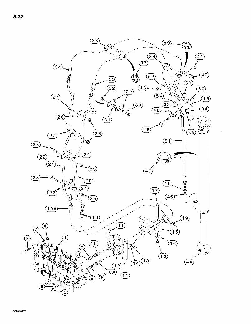
8-32
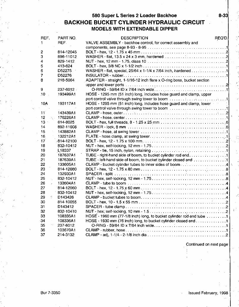
580 Super L Series 2 Loader Backhoe B A C K H O E B U C K E T C Y L I N D E R H Y D R A U L I C C I R C U I T
MODELS WITH EXTENDABLE DIPPER
REF. PART NO. 1 REF
2 814-12045 3 896-11012 4 829-1412 5 413-624 6 D52275 7 D52276 8 218-5064
9 237-6012 10 193499A1
10A 193117A1
11 143439A1 12 . 176226A1 13 614-8025 14 892-11008 15 143882A1 16 132212A1 17 .814-12100 18 832-10412 19 L18337 20 187637A1 21 187639A1 22 133605A1 23 814-12080 24 132930A1 25 832-10412 26 133604A1 27 814-12060 28 832-10412 29 ^ D143426 30 814-10055 31 D143412 32 832-10410 33 108335A1 34 108336A1 35 237-6012 36 103670A1 37 214-3132
8.33
REQ'D DESCRIPTION VALVE ASSEMBLY - backhoe control/for correct assembly and components, see page 8-93 - 8-95 1 BOLT - hex, 12 - 1.75 x 45 mm 2; WASHER - flat, 13.5 x 24 x 3 mm, hardened 2 NUT - hex, 12 mm -1.75, class 10 2 BOLT - hex, 3/8 NC x 1-1/2 inch • -1 WASHER - flat, special, 25/64 x 1-1/4 x 7/64 inch, hardened 1 INSULATOR - rubber. . 1 ADAPTER - straight, 1-1/16-12 inch flare x O-ring boss, bucket section upper and lower ports 2
O-RING - 59/64 ID x 7/64 inch wide. 1 HOSE - 1295 mm (51 inch) long, includes hose guard and clamp, upper port control valve through swing tower to boom . . .1 HOSE - 1295 mm (51 inch) long, includes hose guard and clamp, lower port control valve through swing tower to boom 1 CLAMP - hose, outer .2 CLAMP - hose, center 1 BOLT - hex, full threads, 8 - 1.25 x 25 mm ,6 WASHER - lock, 8 mm .6 CLAMP - hose, at swing tower . 1 PLATE - hose clamp, at swing tower . ,.1 BOLT-hex , 12 - 1.75 x 100 mm . . . 2 NUT - hex, self-locking, 12 mm -1.75 2 STRAP - tie, 15 inch, nylon, retaining . . . . : . . . 1 ; TUBE - right-hand side of boom, to bucket cylinder rod end .1 TUBE - left-hand side of boom, to bucket cylinder closed end .1 CLAMP - bucket cylinder tubes to inner sides of boom 4 BOLT - hex, 12 - 1.75 x 80 mm 8 SPACER-spl i t 8 NUT - hex, self-locking, 12 mm -1.75 8 CLAMP - tube to boom .4 BOLT-hex , 12 - 1.75 x 60 mm 4 NUT - hex, self-locking, 12 mm -1.75 4 CLAMP - bucket tubes to boom 4 BOLT - hex, 10 - 1.5 x 55 mm 2 SPACER - tube clamp NUT - hex, self-locking, 10 mm -1.5 HOSE - 1960 mm (77-1/8 inch) long, to bucket cylinder rod end tube HOSE -1930 mm (76 inch) long, to bucket cylinder closed end
O-RING - 59/64 ID x 7/64 inch wide CLAMP - rubber, hose
2 . . . . . . 2
1 1
. . •. . .1 1
CLAMP - adj, 1-1/4 - 2-1/8 inch dia 2
Continued on next page
Bur 7-3350 Issued February, 1998

8-34
B9504099T
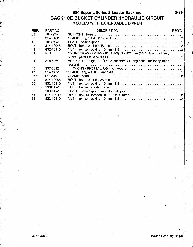
580 Super L Series 2 Loader Backhoe B A C K H O E B U C K E T C Y L I N D E R H Y D R A U L I C C I R C U I T
MODELS WITH EXTENDABLE DIPPER
8-35
REF. PART NO. 38 184297A1 39 214-3132 40 101479A1 41 814-10045 43 832-10410 44 REF
45 218-5064
46 237-6012 47 .214-1472 48 D40236 49 814-10055 50 832-10410 51 : 136436A1 52 183736A1 53 614-10030 54 832-10410
DESCRIPTION REQ'D. SUPPORT-hose • -1 CLAMP - adj, 1-1/4 - 2-1/8 inch dia 2 PLATE - hose support 1 BOLT - hex, 10 -1 .5 x 45 mm 2 NUT - hex, self-locking, 10 mm -1.5 2 CYLINDER ASSEMBLY - 80 (3-1/2) ID x 872 mm (34-5/16 inch) stroke, bucket, parts list page 8-141 .1 ADAPTER - straight, 1-1/16-12 inch flare x O-ring boss, bucket cylinder rod end 1
O-RING - 59/64 ID x 7/64 inch wide. 1 CLAMP - adj, 4-1/16 - 5 inch dia 1 OLAMP-hose • -2 BOLT-hex , 1 0 - 1 . 5 x 5 5 mm 1 NUT - hex, self-locking, 10 mm -1 .5 1 TUBE - bucket cylinder rod end 1 PLATE - hose support, mounts to dipper .1 BOLT - hex, full threads, 10 -1 .5 x 30 mm 2 NUT - hex, self-locking, 10 mm -1.5 2
Bur 7-3350 Issued February,! 1998
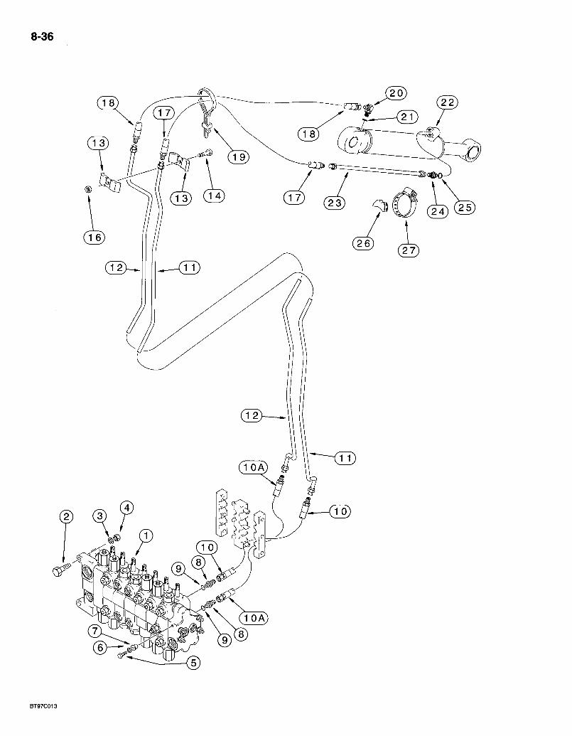
8-36
1 L K l ^
BT97C013
580 Super L Series 2 Loader Backhoe B A C K H O E E X T E N D A B L E D I P P E R H Y D R A U L I C C I R C U I T
8-37
REF. PART NO. 1 REF
2 814-12045 3 896-11012 4 829-1412 5 413-624 6 D52275 7 D52276 8 218-5064
9 237-6012 10 193499A1
10A 193117A1
11 141809A1 12 141811A1 13 D40236 14 814-10050 16 832-10410 17 . 184617A1
18 ,184616A1
19 L i 8337 20 218-5107
21 237-6010 22 1340969C2
23 D140706 24 -. 218-5062
25 237-6010 26 D38648 27 214-1464
DESCRIPTION REQ'D. VALVE ASSEMBLY - backhoe control, for correct assembly and components, see page 8-93 - 8-95 1 BOLT - hex, 12 - 1.75 x 45 mm .2 WASHER - flat, 13.5 x 24 x 3 mm, hardened .2 NUT - hex, 12 mm -1.75, class 10 .2 BOLT - hex, 3/8 NC x 1 -1/2 inch 1 WASHER - flat, special, 25/64 x 1-1/4 x 7/64 inch, hardened .1 INSULATOR - rubber 1 ADAPTER - straight, 1-1/16-12 inch flare x 0-ring boss, extendable dipper section upper and lower ports. •• • • -2;
O-RING - 59/64 ID x 7/64 inch wide . . ^1 HOSE - 1295 mm (51 inch) long, includes hose guard and clamp, upper port control valve through swing tower.to boom, see page 8-33, items 11-19 for hose clamping 1 HOSE - 1295 mm (51 inch) long, includes hose guard and clamp, lower port control valve through swing tower to boom, see page 8-33, items 11-19 for hose clamping 1 TUBE - on boom, to extendable dipper cylinder rod end .1 TUBE - on boom, to extendable dipper cylinder closed end 1 CLAMP - tube, on boom 21 BOLT-hex , 1 0 - 1 . 5 x 5 0 mm 1 NUT - hex, self-locking, 10 mm -1.5 1 HOSE - 850 mm (33-1/2 inch) long, includes hose guard and clamp, extendable dipper cylinder rod end . . .1 HOSE - 700 mm (27^9/16 inch) long, includes hose guard and clamp, extendable dipper cylinder closed end . .1 STRAP- t ie , 15 inch, nylon,, retaining . . . .1 ELBOW - 90 degree, 7/8-14 inch flare X adj 0-ring,boss, extendable dipper cylinder closed end 1
O-RING - 3/4 ID X 3/32 inch wide 1 CYLINDER ASSEMBLY - 76 (3) ID x 1068 mm (42 inch) stroke, extendable dipper, parts list page 8-143 1 TUBE - at extendable dipper cylinder rod end 1 ADAPTER - straight, 7/8-14 inch flare x O-ring boss, extendable dipper cylinder rod end . . .1
O-RING - 3/4 ID X 3/32 inch wide • 1 SPACER - rubber 1 CLAMP - adj, 3-9/16 - 4-1/2 inch dia . . 1
Bur 7-3350 Issued February, 1998
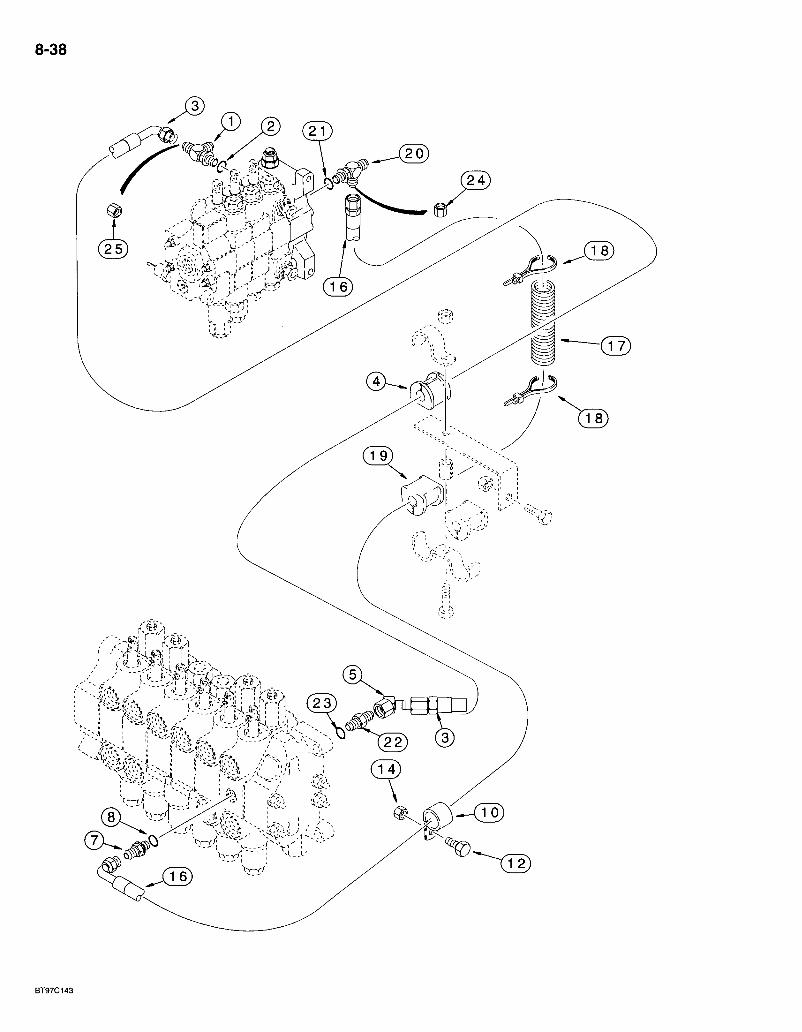
8-38
m
81 ^ J : ^ ' " ^ ^ ^ ; ? ^ !
BT97C143
580 Super L Series 2 Loader Backhoe L O A D E R V A L V E T O B A C K H O E V A L V E H Y D R A U L I C C I R C U I T
IVIODELS WITH OR WITHOUT EXTENDABLE DIPPER WITHOUT AUXILIARY HYDRAULICS
8-39
REF. PARTING. •1 218-5576
2 237-6010 3 243339A1
4 144477A1
5 ., 218-5174
7 218-5057 8 237-6006 10 515-25159 12 614-10025 14 829-1410 16 221553A1
17 D132982 18~ LI 8337 19 D143797
20 218-5243
21 237-6006 22 119895A3 23 237-6010 24 218-754 25 218-335
DESCRIPTION REQ'D. ;TEE - 3/4-16 fl branch x 1-1/16-12 fl x 7/8-14 inch adj O-ring, inlet section lower port
O-RING - 3/4 ID X 3/32 inch wide HOSE -1210 mm (47-11/16 inch) long, swing supply, loader valve inlet section lower port to backhoe valve swing section INSULATOR - rubber, hose, see page 8-7, Ref 17-29 for mounting hardware and alternate mounting configuration ELBOW - 45 degree, 7/8-14 inch flare x swivel, at backhoe valve swing section ADAPTER - straight, 9/16-18 inch flare x O-ring boss. 1
O-RING -15/32 10x5 /64 inch wide. 1 CLAMP - P-type, 5/8 inch ID 1 BOLT - hex, full threads, 10 -1 .5 x 25 mm 1 NUT - hex, 10 mm -1 .5 , class 10.9 1 HOSE - 1860 mm (73-1/4 inch) long, signal, backhoe control valve swing section to loader control valve inlet section 1 SLEEVE - hose guard 2 STRAP - tie, 15 inch, nylon 4 INSULATOR - 5/8 inch, hose, see page 8-7, Ref 17-29 for power beyond hose and mounting hardware and alternate mounting configuration 1 TEE - 9/16-18 inch flare branch x flare x adj O-ring boss, loader valve inlet section and steering pilot hose, see page 5-5 for steering hose
O-RING -15/32 ID x 5/64 inch wide SEAT - valve, swing section inlet.. .
O-RING - 3/4 ID X 3/32 inch wide CAP - hex, 9/16-18.inch, if used CAP-hex , 1-1/16-12 inch, if used
NOTE: See pages 8-41 - 8-55 for auxiliary hydraulics.
Bur 7-3350 Issued February, 1998
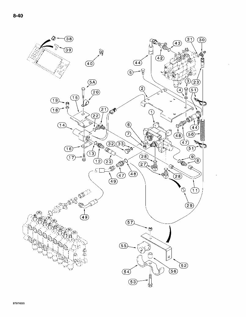
8-40
3 0 ( 3 0 )
V.J---'
BT97N055
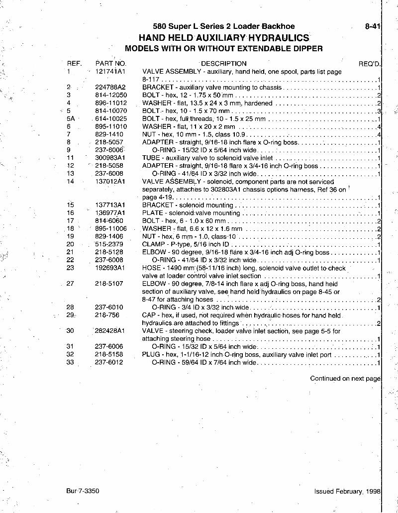
REF. PART NO. 1 121741A1
2 ; 224788A2 3 814-12050 4 896-11012 5 814-10070 5A 614-10025 6 895-11010 7 829-1410 8 218^5057 9 237-6006 11 300983A1 12 ' 218-5058 13 237-6008 14 137012A1
15 137713A1 16 136977A1 17 814-6060 18 895-11006 19 829-1406 20 515-2379 21 218-5128 22 237-6008 23 192693A1
27 218-5107
28 237-6010 29r 218-756
30 282428A1
31 237-6006 32 218-5158 33 237-6012
580 Super L Series 2 Loader Backhoe 8-41 H A N D H E L D A U X I L I A R Y H Y D R A U L I C S
MODELS WITH OR WITHOUT EXTENDABLE DIPPER
DESCRIPTION REQ'D.
VALVE ASSEMBLY - auxiliary, hand held, one spool, parts list page 8-117 .1 BRACKET - auxiliary valve mounting to chassis 1 BOLT - hex, 12 - 1.75 x 50 mm 2 WASHER - flat, 13.5 x 24 x 3 mm, hardened 2 BOLT - hex, 1 0 - 1 . 5 x 7 0 mm 3 BOLT - hex, full threads, 10 -1 .5 x 25 mm 1 WASHER - flat, 11 x 20 x 2 mm . . 4 NUT - hex, 10 mm - 1.5, class 10.9 4 ADAPTER - straight, 9/16-18 inch flare x O-ring boss 1
O-RING -15/32 ID x 5/64 inch wide. 1 TUBE - auxiliary valve to solenoid valve inlet 1 ADAPTER - straight, 9/16-18 flare x 3/4-16 inch O-ring boss 1
O-RING - 41/64 ID x 3/32 inch wide 1 VALVE ASSEMBLY - solenoid, component parts are not serviced separately, attaches to 302803A1 chassis options harness, Ref 36 on page 4-19 : -1 BRACKET - solenoid mounting 1 PLATE - solenoid valve mounting 1 BOLT - hex, 6 -1 .0 X 60 mm 2 WASHER - flat, 6.6 x 12 x 1.6 mm 2 NUT - hex, 6 mm -1 .0 , class-10 . .2 CLAMP - P-type, 5/16 inch ID 1 ELBOW - 90 degree, 9/16-18 flare x 3/4-16 inch adj G-ring boss 1
O-RING - 41/64 ID x 3/32 inch wide. . . . . 1 HOSE - 1490 mm (58-11/16 inch) long, solenoid valve outlet to check valve at loader control valve inlet section 1 ELBOW - 90 degree, 7/8-14 inch flare x adj O-ring boss, hand held section of auxiliary valve, see hand held hydraulics on page 8-45 or 8-47 for attaching hoses . . . ; 2
O-RING - 3/4 ID X 3/32 inch wide 1 CAP - hex, if used, not required when hydraulic hoses for hand held hydraulics are attached to fittings 2 VALVE - steering check, loader valve inlet section, see page 5-5 for attaching steering hose 1
O-RING - 15/32 ID x 5/64 inch wide. . . . .1 PLUG - hex, 1-1/16-12 inch O-ring boss, auxiliary valve inlet port .1
O-RING - 59/64 ID x 7/64 inch wide 1
Continued on next page
Bur7-3350 Issued February, 1998
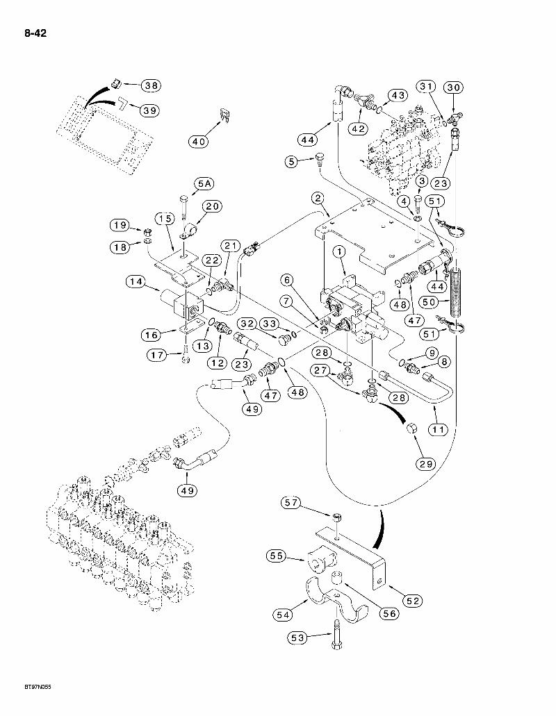
8-42
3 1 ) ( 3 0 )
Wr--; " t- '
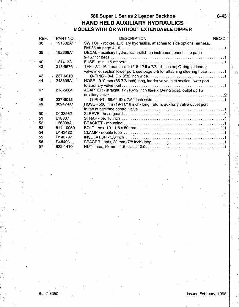
580 Super L Series 2 Loader Backhoe H A N D H E L D A U X I L I A R Y H Y D R A U L I C S
MODELS WITH OR WITHOUT EXTENDABLE DIPPER
8-43
REF. PART NO. 38 191532A1
39 . 192299A1
40 121413A1 42 218-5576
43 237-6010 44 243338A1
47 218-5064
48 237-6012 49 302474A1
50 D132982 51 LI 8337 52 136008A1 53 814-10050 54 D143422 55 D143797 56 R46493 57 829-1410
DESCRIPTION REQ'D. SWITCH - rocker, auxiliary hydraulics, attaches to side options harness, Ref 35 on page 4-19 1 DECAL - auxiliary hydraulics, switch on instrument panel, see page 9-157 for decal 1 FUSE - mini, 15 ampere 1 TEE - 3/4-16 fl branch x 1-1/16-12 fl x 7/8-14 inch adj O-ring, at loader valve inlet section lower port, see page 5-5 for attaching steering hose 1
O-RING - 3/4 ID X 3/32 inch wide 1 HOSE - 910 mm (35-7/8 inch) long, loader valve inlet section lower port to auxiliary valve port 1 ADAPTER - straight, 1-1/16-12 inch flare x O-ring boss, outlet port at auxiliary valve -2.
O-RING - 59/64 ID x 7/64 inch wide 1 HOSE - 500 mm (19-11/16 inch) long, return,sauxiliary valve outlet port to tee at backhoe control valve 1 SLEEVE - hose guard .2 STRAP- t ie , 15 inch 4 BRACKET - mounting .1 BOLT-hex , 1 0 - 1 .5x50 mm ; i CLAMP - double tube 1 INSULATOR - 5/8 inch 1 SPACER - split, 22 mm (7/8 inch) long 1 NUT - hex, 10 mm -1 .5 , class 10.9 .1
Bur 7-3350 Issued February, 1998
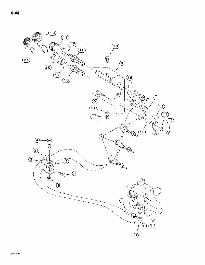
8-44
580 Super L Series 2 Loader Backhoe *HAND HELD AUXBLIARY HYDRAULIGS
AUXILIARY VALVE TO QUICK DISCONNECT COUPLINGS MODELS WITH 31 GALLON FUEL TANK
8-45
REF. PART NO. 1 191215A1
2 - D34033 3 180318A1 4 614-10025 6 829-1410 7 LI 8337 8 297635A1 9 827-10050 10 131600A1 11 191075A1 12 829-1410 13 614-10025 14 895-11010 15 218-1256 16 126155A1 17 237-6012 18 122179A1
19 137343A1 19 193261A1 20 122178A2
21 137344A1 21 193262A1
REQ'D. DESCRIPTION HOSE - 2460 mm (96-7/8 inch) long, auxiliary valve to quick disconnect couplings, see page 8-41 for 218-5107 elbows at auxiliary valve 2 CLAMP - P-type, 1-3/16 inch ID . . 2 BRACKET-hose support . . . . .1 BOLT - hex, full threads, 10 - 1.5 x 25 mm . 1 NUT - hex, 10 mm -1.5, class 10.9 .1 STRAP-tie, 15 inch 3 BRACKET - hose support to quick disconnect couplings 1 BOLT - hex, 10 - 1.5x50 mm, class 10.9 1 SPACER - clamp. 1 CLAMP-double -1 NUT- hex, 10 mm -1.5, class 10.9 2 BOLT - hex, full threads, 10-1.5 x 25 mm 1 WASHER - fiat, 11 x 20 x 2 mm 2 NUT-hex, lock, bulkhead, 1-1/16 inch NF . .2 CONNECTOR - straight, bulkhead 2
0-RING - 59/64 ID x 7/64 inch wide. 2 COUPLING - quick disconnect, female, component parts are not serviced separately CAP - female coupling, aluminum, if used. CAP - female coupling, black rubber, if used COUPLING - quick disconnect' male, component parts are not serviced separately CAP - male coupling, aluminum, if used CAP - male coupling, black rubber, if used
* NOTE: For a continuation of special parts used on models with hand held auxiliary hydraulics, control cables to auxiliary valve, see page 8-49.
Bur 7-3350 Issued February, 1998
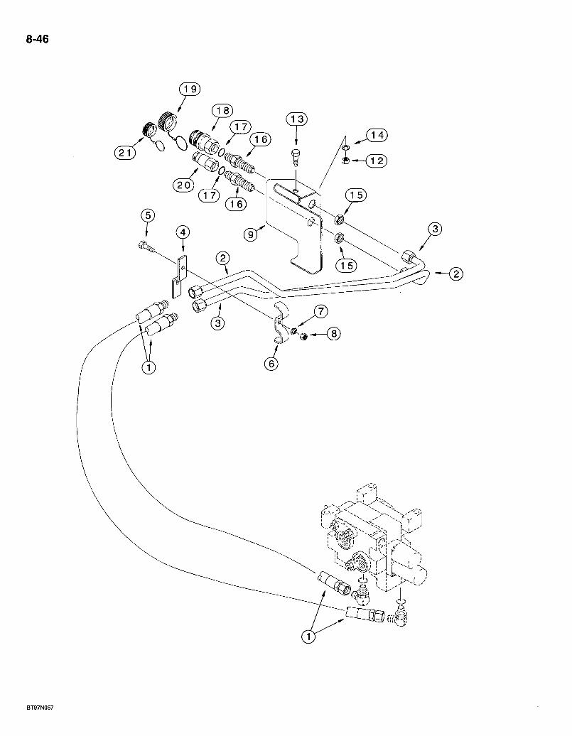
8-46
BT97N057
580 Super L Series 2 Loader Backhoe *HAND HELD AUXILIARY HYDRAULICS
AUXILIARY VALVE TO QUICK DISCONNECT COUPLINGS MODELS WITH 40 GALLON FUEL TANK
8-47
REF.:. PART NO. 1 302501A1
2 301700A1 3 301698A1 4 301355A1 5 814-10050 6 D42833 7 892-11010 8 829-1410 9 : 300490A1 12 , 829-1410 13 614-10025 14 895-11010 15 218-1256 16 126155A1-17 237-6012 18 122179A1
19 137343A1 19 193261A1 20 122178A2
21 137344A1 21 193262A1
D E S C R I P T I O N REQ:D. H O S E -1340 mm (52-13/16 inch) long, auxiliary valve to quick disconnect couplings, see page 8-41 for 218-5107 elbows at auxiliary valve : -2 T U B E - to male coupling T U B E - to female coupling B R A C K E T - tube mounting B O L T - hex, 10- 1.5x50 mm C L A M P - t u b e W A S H E R - lock, 10 mm N U T - hex, 10 mm -1.5, class 10.9 B R A C K E T - hose support to quick disconnect couplings N U T - hex, ,10 mm -1,5, class 10.9 BOLT-hex , full threads, 10- 1.5x25 mm W A S H E R - flat, 11 X 20 X 2 mm . . . . . N U T - hex, lock, bulkhead, 1-1/1,6 inch N F 2 C O N N E C T O R - straight, bulkhead 2
d - R I N G - 59/64 ID X 7/64 inch wide 2 C O U P L I N G - quick disconnect, female, component parts are not sen/iced separately C A P - female coupling,:aluminum, if used C A P - female coupling, black rubber, if used C O U P L I N G - quick disconnect, male, component parts are not sen/iced separately C A P - male coupling, aluminum, if used C A P - male coupling, black rubber, if used
* NOTE: For a continuation of special parts used on models with hand held auxiliary hydraulics, control cables to auxiliary valve, see page 8-49.
Bur 7-3350 Issued February, 1998

8-48
580 Super L Series 2 Loader Backhoe *HAND HELD AUXILIARY HYDRAULICS
CONTROL CABLES TO AUXILIARY VALVE MODELS WITH 31 OR 40 GALLON FUEL TANK
8-49
REF. PART NO. 1 139227A1 2 191076A1
3 614-8025 4 895-1.1008 5 6U-10025 6 895-11010 7 829-1410 8 139043A1 9 123942A1 10 . 96790C2 11 96846C2 12 733-2012 13 1340478C1 14 1280055C2 15 614-6020 16 895-11006 17 892-11006 18 814-10045 23 139230A1 24 83-1108
25 179683A1
26 192300A1
27 123943A1 28 84-2106 29 225-14210
REQ'D DESCRIPTION KNOB-push pull, detent 1 PLATE - control panel, hand held auxiliary hydraulics, left-hand mounting hole uses existing mounting hardware 1 BOLT - hex, full threads, 8 - 1.25 x 25 mm 2] WASHER - flat, 9 x 17 x 1.6 mm .2 BOLT - hex, full threads, 10 -1.5 x 25 mm .2j WASHER - flat, 11 x 20 x 2 mm r2| NUT - hex, 10 mm -1.5, class 10.9 2 BRACKET - cable support 1 CABLE - push pull detent, lower auxiliary valve spool. 1 CLEVIS - cable, push pull cable end 1 PIN - clevis. . . . : :1 PIN - cotter, 2 x 12 mm . .1 HOUSING - cable, lower auxiliary valve spool 1 FLANGE - cable support • .1 BOLT - hex, full threads, 6 -1.0 x 20 mm 2 WASHER - flat, 6.6 x 12 x 1.6 mm 2 WASHER - lock, 6 mm . ..2 BOLT -hex, 10- 1.5 x45 mm . 1 KNOB - rotary, flow control .1 SCREW - set, hex socket headless. No. 10 NC x 1/2 inch, cup point, flow contrbhknob .1 DECAL - hand held auxilliary hydraulics, control panel plate, see page 9-157 for decal 1 DECAL - remote auxiliary hydraulics, inside left-hand door on side of steering wheel panel, see page 9-157 for decal 1 CABLE - flow control, rotary, upper auxiliary valve spool SCREW - set, hex socket headless. No. 10 NF x 3/8 inch, cone point NUT-hex. No. 10NF
* NOTE: For a continuation of special parts used on models with hand held auxiliary hydraulics, auxiliary valve to quick disconnect couplings, see page 8-45 or 8-47.
Bur 7-3350 Issued February, 1998
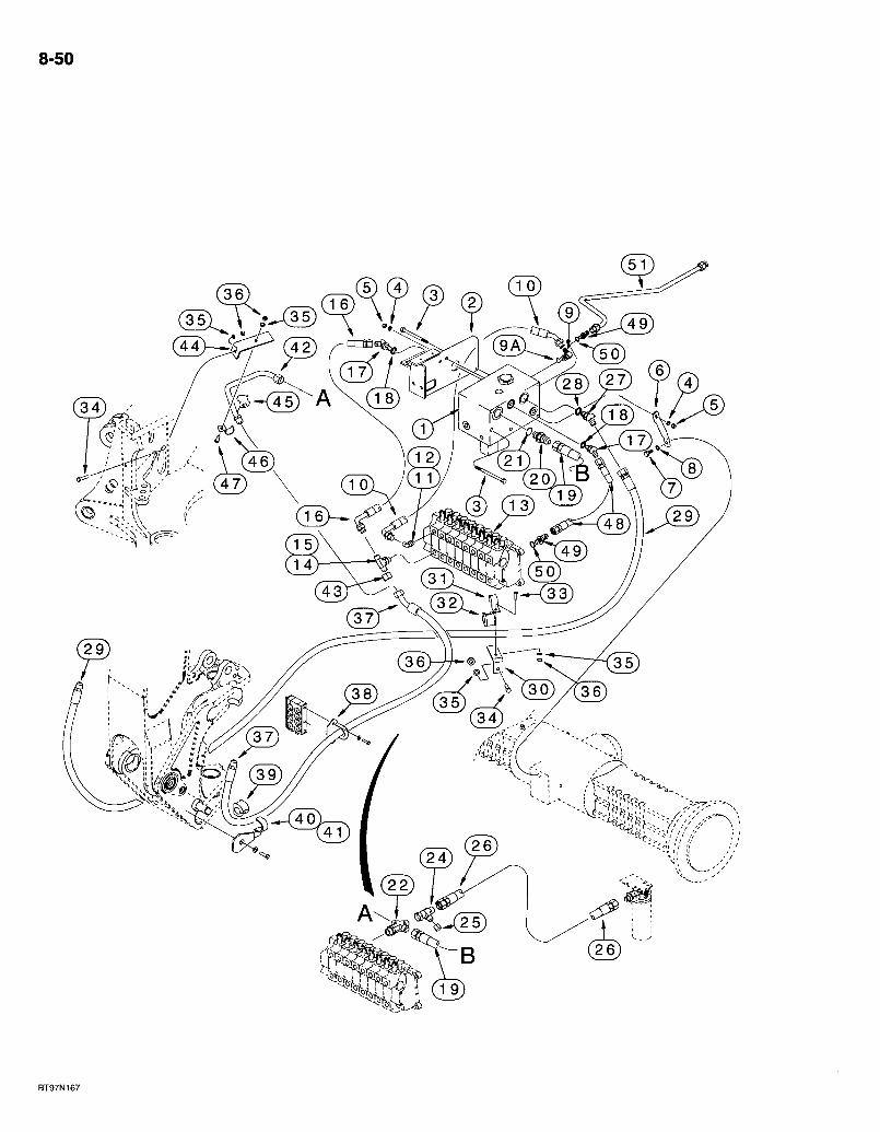
8-50
<5 -^r;!)
BT97N167
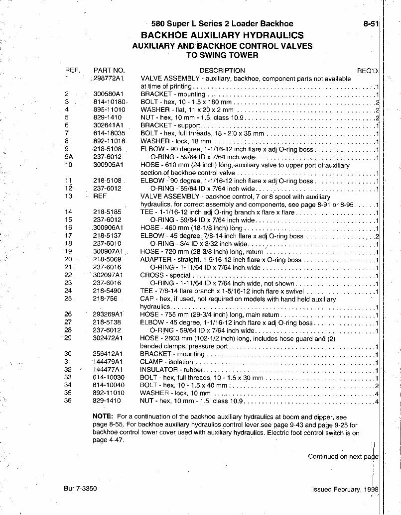
580 Super L Series 2 Loader Backhoe BACKHOE AUXILIARY HYDRAULICS
AUXILIARY AND BACKHOE CONTROL VALVES TO SWING TOWER
8-51
REF. PART NO. 1 ;_298772A1
2 300580A1 814-10180
4 895-11010 5 829-1410 6 302641A1 7 614-18035 8 892-11018 9 218-5108 9A 237-6012 10 300905A1
11 218-5108 12 237-6012 13 REF
14 218-5185 15 237-6012 16 300906A1 17 218-5137 18 237-6010 19 300907Ai 20 218-5069 21 • 237-6016 22 302097A1 23 237-6016 24 218-5490 25 218-756
26 293269A1 27 218-5138 28 237-6012 29 302472A1
30 256412A1 31 144479A1 32 144477A1 33 614-10030 34 814-10040 35 892-11010 36 829-1410
REQ'D DESCRIPTION VALVE ASSEMBLY - auxiliary, backinoe, component parts not available at time of printing BRACKET - mounting BOLT - hex, 10 -1.5 x 180 mm . . 2j WASHER - flat, 11 x 20 x 2 mm 2 NUT-hex, 10 mm -1.5, class 10.9 2 BRACKET - support BOLT - hex, full threads, 18 - 2:0 x 35 mm . . WASHER - lock, 18 mm ELBOW - 90 degree, 1-1/16-12 inch flare x adj O-ring boss
O-RING - 59/64 ID x 7/64 inch wide. HOSE - 610 mm (24 inch) long, auxiliary valve to upper port of auxiliary section of backhoe control valve ELBOW - 90 degree, 1-1/16-12 inch flare x adj O-ring boss
O-RING - 59/64 ID x 7/64 inch wide VALVE ASSEMBLY - backhoe control, 7 or 8 spool with auxiliary hydraulics, for correct assembly and components, see page 8-91 or 8-95 TEE - 1-1/16-12 inch adj O-ring branch x flare x flare
O-RING - 59/64 ID x 7/64 inch wide HOSE - 460 mm (18-1/8 inch) long ELBOW - 45 degree, 7/8-14 inch flare x adj O-ring boss
O-RING - 3/4 ID X 3/32 inch wide HOSE - 720 mm (28-3/8 inch) long, return ADAPTER - straight, 1-5/16-12 inch flare x O-ring boss
O-RING - 1-11/64 ID X 7/64 inch wide CROSS - special
O-RING -1-11/64 ID X 7/64 inch wide, not shown . . . . ; TEE - 7/8-14 flare branch x 1-5/16-12 inch flare x swivel CAP - hex, if used, not required on models with hand held auxiliary hydraulics HOSE - 755 mm (29-3/4 inch) long, main return ELBOW - 45 degree, 1-1/16-12 inch flare x adj O-ring boss
O-RING - 59/64 ID x 7/64 inch wide HOSE - 2603 mm (102-1/2 inch) long, includes hose guard and (2) banded clamps, pressure port BRACKET - mounting CLAMP - isolation INSULATOR - rubber BOLT - hex, full threads, 10 - 1.5 x 30 mm BOLT - hex, 10-1.5,x 40 mm .2 WASHER-lock, 10 mm 4 NUT - hex, 10 mm - 1.5, class 10.9 4
NOTE: For a continuation of the backhoe auxiliary hydraulics at boom and dipper, see page 8-55. For backhoe auxiliary hydraulics control lever see page 9-43 and page 9-25 for backhoe control tower cover used vyith auxiliary hydraulics. Electric foot control switch is on page 4-47.
Bur 7-3350
Continued on next page
Issued February, 1998
8-52
, ^(5) (A) ^
/ - A X 1
- ( 4 5 ) ^ A \C l8
REF. 37
38 39 40 41 42 43 ,44 45 46 47 48 49 50 51
580 Super L Series 2 Loader Backhoe BACKHOE AUXILIARY HYDRAULICS
AUXILIARY AND BACKHOE CONTROL VALVES TO SWING TOWER
8-53
PART NO. 253740A1
252737A1 144477A1 249775A1 249773A1 300939A1 218-335 282842A1 D74182 D143411 614-10025 300952A1 218-5062 237-6010 300884A1
REQ'D DESCRIPTION HOSE - 1760 mm (69-5/16 inch) long, includes hose guard and (2) banded clamps, lower port of backhoe control valve auxiliary section to left-hand side of dipper CLAMP - auxiliary hose, at pivot block 2 INSULATOR - rubber, at swing tower 2 CLAMP - hose; left-hand, at swing tower CLAMP - hose, right-hand, at swing tower TUBE - low pressure return CAP-hex, 1-1/16-12 inch BRACKET - mounting, tube INSULATOR - tube CLAMP - P-type, 3/4 inch ID BOLT - hex, full threads, 10 -1.5 x 25 mm HOSE - 335 mm (13-3/16 inch) long ADAPTER - straight; 7/8-14 inch flare x O-ring boss
0-RING-3/4 ID X3/32.inch wide TUBE - small pump supply . . .
NOTE: For a continuation of the backhoe auxiliary hydraulics at boom and dipper, see page 8-55. For backhoe auxiliary hydraulics control lever see page 9-43 and page 9-25 for backhoe control tower cover used with auxiliary hydraulics. Electric foot control switch is on page 4-47.
Bur 7-3350 Issued February, 1998
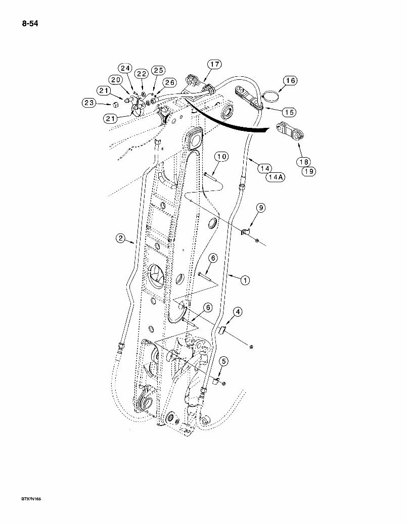
8-54
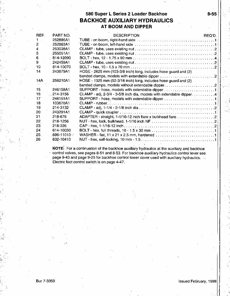
580 Super L Series 2 Loader Backhoe BACKHOE AUXILIARY HYDRAULICS
AT BOOM AND DIPPER
8-55
REF. PARTNO. DESCRIPTION REQ'D. 1 252885A1 TUBE - on boom, right-hand side , . . . .1 2 252883A1 TUBE - on boom, left-hand side 1 4 253038A1 CLAMP - tube, uses existing nut 2 5 255051A1 CLAMP - tube, uses existing nut 2 6 ; 814-12090 BOLT-hex, 12- 1.75x90 mm. 4 9 , 242459A1 CLAMP - tube, uses existing nut 2 10 814-10070 BOLT-hex, 10-1 .5x70 mm .2 14 243679A1 HOSE - 2625 mm (103-3/8 inch) long, includes hose guard and (2)
banded clamps, models with extendable dipper 2 14A 256210A1 HOSE - 1325 mm (52-3/16 inch) long, includes hose guard: and (2)
banded clamps, models without extendable dipper 2 15 246158A1 SUPPORT - hose, models with extendable dipper 1 16 214-3156 CLAMP - adj, 2-3/4 - 3-5/8 inch dia, models with extendable dipper. 4 17 246151A1 SUPPORT-hose, models with extendable dipper 1 18 103670A1 CLAMP - rubber. : .1 19 214-3132 CLAMP-adj, 1-1/4-2-1/8 inch dia 2 20 243291A1 CLAMP - quick coupler 1 21 218-676 ADAPTER - straight, 1-1/16-12 inch flare x bulkhead flare .2 22 218-1256 NUT - hex, lock, bulkhead, 1-1/16 inch NF 2 23 218-335 CAP - hex, 1 -1 /16-12 inch 2 24 614-10030 BOLT-hex, full threads, 10-1 .5x30 mm 1 25 .896-11010- WASHER-flat, 11 X 21 x2.5 mm, hardened .1 26 832-10410 NUT - hex, self-locking, 10 mm -1.5 . . .1
NOTE: For a continuation of the backhoe auxiliary hydraulics at the auxiliary and backhoe - control valves, see pages 8-51 and 8-53. For backhoe auxiliary hydraulics control lever see
page 9-43 and page 9-25 for backhoe control tower cover used with auxiliary hydraulics. -Electric foot control switch is on page 4-47.
Bur 7-3350 Issued February, 1998

8-56
G R O U N D A T
L O A D E R C O N T R O L
T O W E R
T O S I D E
C O N S O L E H A R N E S S
F U S E B L O C K
T O
B O O M L O C K
H A R N E S S
O N B O O M
B9504049T

REF.
580 Super L Series 2 Loader Backhoe BACKHOE BOOM LOCK HYDRAULIC
AND ELECTRICAL CIRCUIT AT CONTROL TOWER AND BACKHOE VALVE
8.57
PART NO. 189111A1
REQ'D DESCRIPTION KIT - backhoe boom lock, also includes parts on page 8-59, L111356 decal on page 9-157 and an instruction sheet, order components 1
VALVE ASSEMBLY - backhoe control, for correct assembly and components, see page 8-89.- 8-95, for valve mounting see page 8-23. . . . . .1 ELBOW - 90 degree, adjustable, see page 8-59 for attaching hose 1
O-RING - 3/4 ID X 3/32 inch wide 1 HARNESS - boom lock, at control tower to fuse block on side console harness 1 CLIP - harness 2 STRAP - tie, 15 inch .2 SWITCH - toggle, boom lock 1 PLATE-trim 1 BOOT - toggle switch 1 HOLDER - fuse, includes cap, at backhoe control tower 1 FUSE - 3AG, 5 ampere, boom lock ! . . . .1
NOTE: See page 8-59 for continuation of backhoe boom lock hydraulic and electrical circuit.
1 *REF .
2 189414A1 3 237-6010 4 189601A1
5 LI 00659 6 L18337 7 D67251 8 LI 05735 9 LI 01998 10 376852R91 11 223-26
*NOTE: Not included in 189111A1 kit, purchase separately.
Bur 7-3350 Issued February, 1998
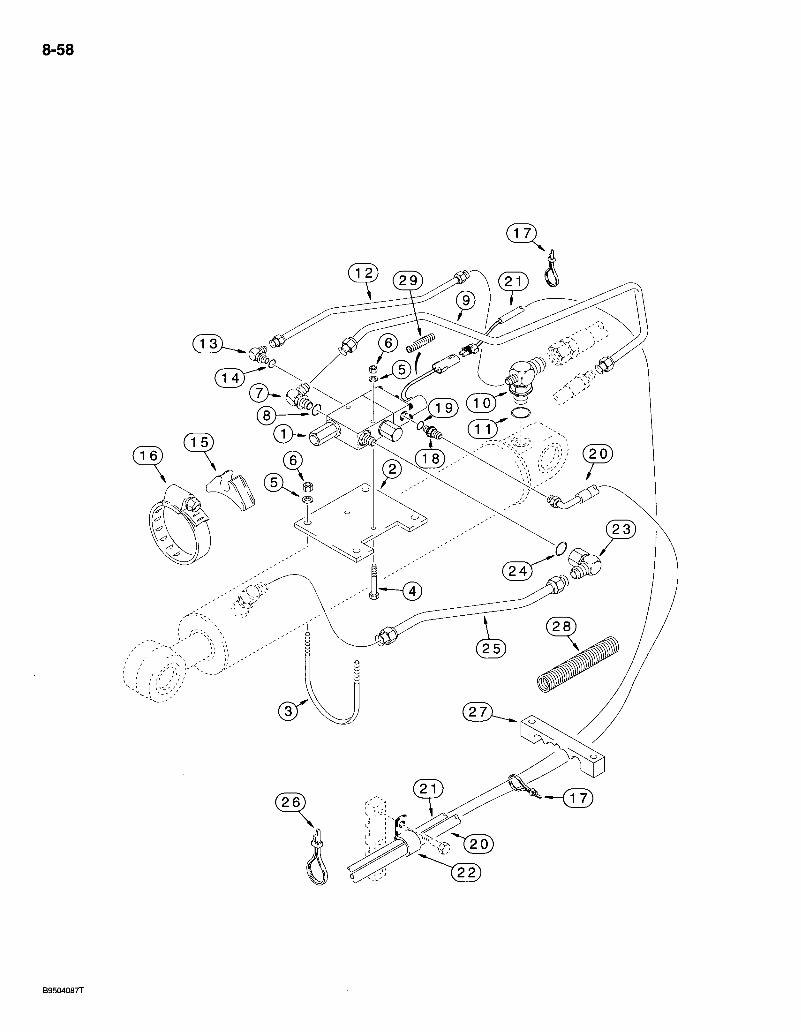
8-58
)C^9)(W
0

REF. PART NO. 189111A1
1 189957A1
2 D150054 3 D150053 4 413-648 5 495-11041 6 231-1446 7 , 218-5118 8 237-6016 9 192025A1 10 187677A1
11 237-6012 12 189709A1 13 218-5283 14 237-6006 15 D142787 16 214-31104 17 LI 8337' 18 218-5359 19 237-6008 20 189103A1
21 189263A1 22 515-25190 23 218-5382 24 237-6016 25 187612A1
26 D147773 27 221330A1 28 220276A1 29 D121385
580 Super L Series 2 Loader Backhoe BACKHOE BOOM LOCK HYDRAULIC
AND ELECTRICAL CIRCUIT AT BOOM CYLINDER
8-59
REQ'D. DESCRIPTION KIT - backhoe boom lock, continued from previous page, order components 1
VALVE ASSEMBLY - solenoid, backhoe boom lock, includes (2) 321-6046 warning decals, parts list page 8-121 1 PLATE - valve nriounting. 1 U-BOLT - 3/8 inch 2 BOLT - hex, 3/8 NC x 3 inch .2 WASHER - flat, 13/32 x 13/16 x 1/16 inch 6 NUT - hex, self-locking, 3/8 inch NC 6 ELBOW - 90 degree, 1-1/16-12 flare x 1-5/16T12 inch adj 0-ring boss
O-RING - 1-11/64 ID x 7/64 inch wide TUBE - valve port, attaches to item 34 hose on page 8-25 . . . . . . . . . TEE - reducer. boom cylinder closed end, attaches to item 23 hose on page 8-25
O-RING - 59/64 ID x 7/64 inch wide TUBE-pilot port. ELBOW - 90 degree, 7/16-20 flare x 9/16-18 inch adj O-ring boss . . .
O-RING -15/32 ID x 5/64 inch wide INSULATOR - rubber CLAMP - adj, 5-3/4 - 6-5/8 inch dia . . STRAP-tie, 15 inch ADAPTER - straight, 7/16-20 flare x 3/4-16 inch O-ring boss
O-RING - 41/64 ID x 3/32 inch wide HOSE - 3700 mm (145-11/16 ihch) long, return, attaches to elbow at backhoe valve, see item 2 on page,8-57 HARNESS - boom lock valve to control tower harness CLAMP - P-type, 3/4 inch ID, return hose ELBOW - 90 degree, 1-1/16-12 flare x 1-5/16-12 inch swivel
O-RING -1-11/64 ID X 7/64 inch wide TUBE - boom lock valve to boom cylinder rod end, see page 8-25, item 29 for elbow ' STRAP-tie . . . . CLAMP - hose and harness. SLEEVE - hose guard GUARD - harness protection
Bur 7-3350 Issued February, 1998
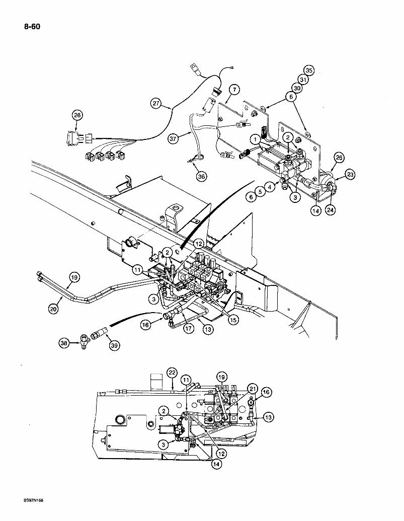
8-60
@
®
®
BS97N168
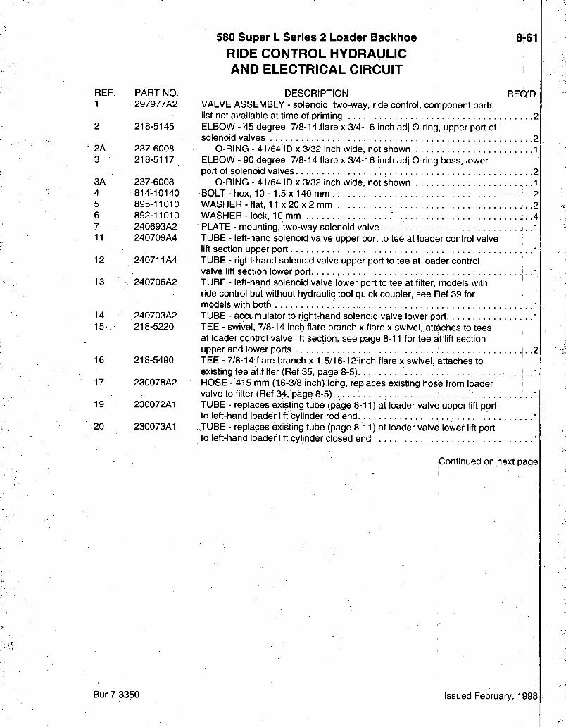
REF. PART NO. 1 297977A2
2 218-5145
2A 237-6008 3 • 218-5117
3A 237-6008 4 814-10140 5 895-11010 6 892-11010 7 240693A2 11 240709A4
12 240711A4
13 240706A2
14 240703A2 15 218-5220
16 218-5490
17 230078A2
19 230072A1
20 230073A1
580 Super L Series 2 Loader Backhoe 876I
RIDE CONTROL HYDRAULIC AND ELECTRICAL CIRCUIT
DESCRIPTION REQ'D. VALVE ASSEMBLY - solenoid, two-way, ride control, component parts list not available at time of printing 2 ELBOW - 45 degree, 7/8-14 flare x 3/4-16 inch adj 0-ring, upper port of solenoid valves 2
0-RING - 41/64 ID X 3/32 inch wide, not shown . 1 ELBOW - 90 degree, 7/8-14 flare x 3/4-16 inch adj 0-ring boss, lower port of solenoid valves 2
0-RING - 41/64 ID x 3/32 inch wide, not shown ,. .1 BOLT - hex, 10-1.5 x 140 mm '. .2 WASHER - flat, 11 x 20 x 2 mm .2 WASHER-lock, 10 mm . .4 PLATE - mounting, two-way solenoid valve .1 TUBE - left-hand solenoid valve upper port to tee at loader control valve lift section upper port 1 TUBE - right-hand solenoid valve upper port to tee at loader control valve lift section lower port .;.. 1 TUBE - left-hand solenoid valve lower port to tee at filter, models with ride control but without hydraulic tool quick coupler, see Ref 39 for models with both 1 TUBE - accumulator to right-hand solenoid valve lower port. 1 TEE - swivel, 7/8-14 inch flare branch x flare x swivel, attaches to tees at loader control valve lift section, see page 8-11 for tee at lift section upper and lower ports .2 TEE - 7/8-14flare branch x 1-5/16-12Hnch flare x swivel, attaches to existing tee at.filter (Ref 35, page 8-5). . . . . .1 HOSE - 415 mm.(1 6-3/8 inch) long,.replaces existing hose from loader i valveto filter(Ref 34, page8-5) . . . .1 TUBE - replaces existing tube (page 8-11) at loader valve upper lift port to left-hand loader lift cylinder rod end .1 TUBE - replaces existing tube (page 8-11) at loader valve lower lift port to left-hand loader lift cylinder closed end 1
Continued on next page
Bur 7-3350 Issued February, l!998
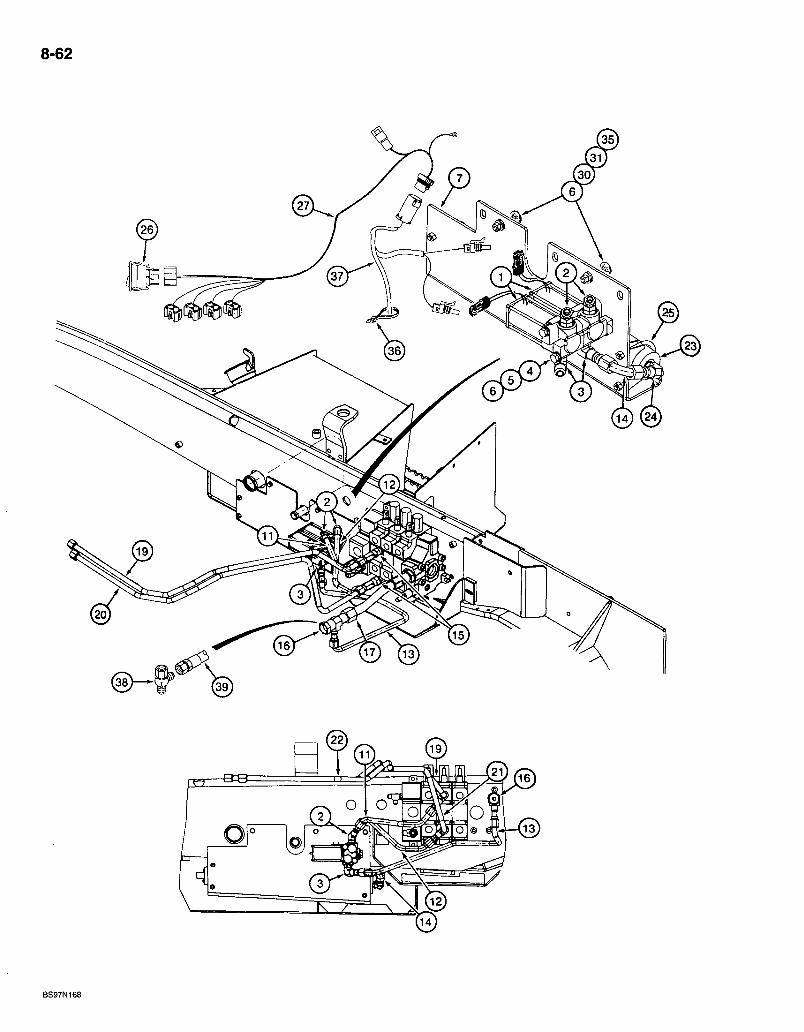
8-62
®
@
BS97N168

580 Super L Series 2 Loader Backhoe RIDE CONTROL HYDRAULIC AND ELECTRICAL CIRCUIT
8-63
REF. 23
24 24A 25 26 27 .
30 31 32 33
34
35 36 37 38
39
PART NO. 234412A1
218-5600 237-6008 A13240 235002A1 296508A2
711-10030 829-1410 121413A1
:255927A1
256318A1
895-15010 L18337 302803A1 218-5220
293037A1
DESCRIPTION REQ'D. ACCUMULATOR ASSEMBLY - hydraulic, ride control, parts list page 8-123 1 ELBOW - 90 degree, 7/8-14 flare x 3/4-16 inch adj 0-ring boss 1
0-RING - 41/64 ID x 3/32 inch wide, not shown .1 CLAMP - two piece, includes hardware 2 SWITCH - ride control, mounts in side instrument panel console .1 HARNESS - side console options, ride control switch to chassis options harness and fuse block 1 BOLT - carriage, 10 -1.5 x 30 mrn .2 NUT - hex, 10 mm - 1.5, class 10.9 .2 FUSE - mini, 15 ampere, not shown .M DECAL - Warning, do not turn the ride control on, if the loader arms and bucket are holding the front of the machine off the ground, mounts on console by ride control switch, not shown, see page 9-157 for decal .1 DECAL - Warning, pressure accumulator in loader hydraulic system, mounts on accumulator mounting plate, not shown, see page 9-157 for decal .1 WASHER - flat, 11 X 24 X 2 mm .2 STRAP-tie, 15 inch .2 HARNESS - chassis options, connects to side console options harness .1 TEE - swivel, 7/8-14 inch flare:branch x flare x swivel, models with both ride control and hydraulic tool quick coupler .1 TUBE - left-hand solenoid valve lower port to tee at filter, models with both ride control and hydraulic tool quick coupler .1
Bur 7-3350 Issued February, 1998
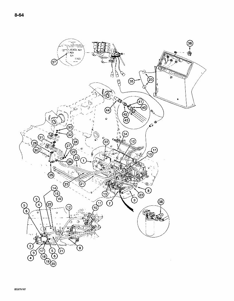
8-64
0
BS97N187
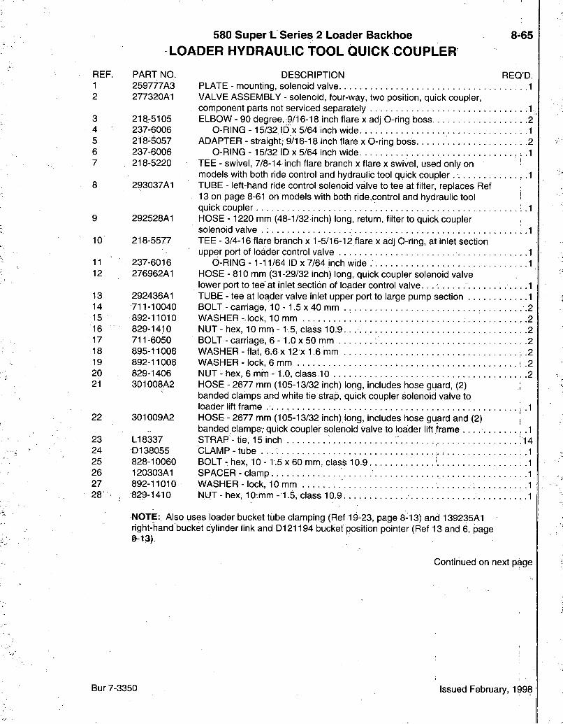
580 Super L Series 2 Loader Backhoe LOADER HYDRAULIC TOOL QUICK COUPLER
8 65
REF. PART NO. DESCRIPTION REQ'D. 1 259777A3 PLATE - mounting, solenoid valve 2 277320A1 VALVE ASSEMBLY - solenoid, four-way, two position, quick coupler,
component parts not serviced separately 3 218.-5105 ELBOW-90 degree, 9/16-18 inch flare xadjO-ring boss 4 237-6006 O-RING -15/32 ID x 5/64 inch wide 5 218-5057 ADAPTER - straight; 9/16-18 inch flare x 0-ring boss 6 237-6006 O-RING -15/32 ID x 5/64 inch wide 7 . 218-5220 TEE-swivel, 7/8-14 inch flare branch X flare X swivel, used only on
models with both ride control and hydraulic tool quick coupler 8 293037A1 TUBE - left-hand ride control solenoid valve to tee at filter, replaces Ref
13 on page 8-61 on models with both ride.control and hydraulic tool < quick coupler
9 292528A1 HOSE - 1220 mm (48-1/32 inch) long, return, filter to quick coupler , solenoid valve . :
10 218-5577 TEE - 3/4-16 flare branch x 1-5/16-12 flare x adj O-ring, at inlet section upper port of loader control valve i
11 237-6016 O-RING- 1-11/64 10x7/64 inch wide. 12 276962A1 HOSE - 810 mm (31-29/32 inch) long, quick coupler solenoid valve
lower port to tee at inlet section of loader control valve. 13 292436A1 TUBE - tee at loader valve inlet upper port to large pump section 14 711-10040 BOLT-carriage, 10-1.5x40 mm . .2 15 892-11010 WASHER - lock, 10 mm . . . . . .2 16 829-1410 NUT-hex, 10 mm-1.5, class 10.9. . . 2 17 711-6050 BOLT - carriage, 6 -1.0 x 50 mm 2 18 895-11006 WASHER - flat, 6.6 x12 X 1.6 mm ..2 19 892-11006 WASHER - lock, 6 mm . . . . .2 20 829-1406 NUT - hex, 6 mm -1.0, class 10 2 21 301008A2 HOSE-2677 mm (1.05-13/32 inch) long, includes hose guard, (2)
banded clamps and white tie strap, quick coupler solenoid valve to loader lift frame .1
22 301009A2 HOSE - 2677 mm (105-13/32 inch),long, includes hose guard and (2) | banded clamps, quick coupler solenoid valve to loader lift frame 1
23 L18337 STRAP - tie, 15 inch ;14 24 D138055 CLAMP - tube . . . .1 25 828-10060 BOLT - hex, 10 - 1.5 x 60 mm, class 10.9 . . . .1 26 120303A1 SPACER - clamp 1 27 892-11010 WASHER-lock, 10mm .1 28 , 829-1410 NUT-hex, 10 mm-1.5, class 10.9. .1
NOTE: Also uses loader bucket tube clamping (Ref 19-23, page 8-13) and 139235A1 right-hand bucket cylinder link and D121194 bucket position pointer (Ref 13 and 6, page @-13).
Continued on next page
Bur 7-3350 Issued February, 1998
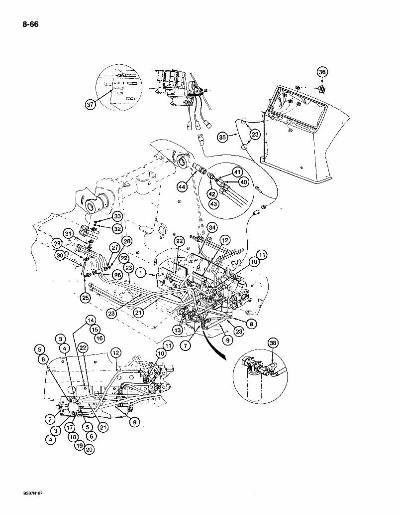
8-66
r
BS97N187
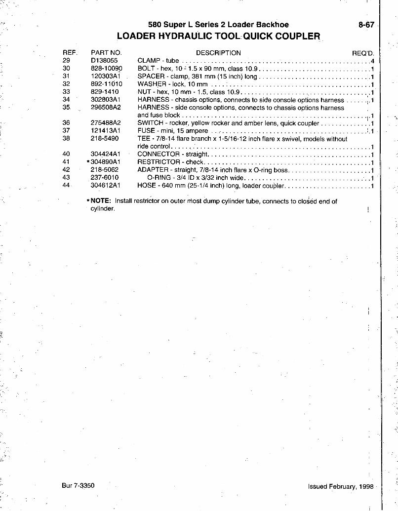
580 Super L Series 2 Loader Bacldioe LOADER HYDRAULIC TOOL QUICK COUPLER
8-67
REF. PART NO. 29 D138055 30 828-10090 31 120303A1 32 892-11010 33 829-1410 34 302803A1 35 296508A2
36 275488A2 37 121413A1 38 218-5490
40 304424A1 41 *304890A1 42 218-5062 43 237-6010 44 304612A1
DESCRIPTION REOjD. CLAMP-tube 4 BOLT - hex, 10 -1.5 x 90 mm, class 10,9.. SPACER - clamp, 381 mm (15 inch) long WASHER-lock, 10 mm . . . . NUT - hex, 10 mm -1.5, class 10.9 HARNESS - chassis options, connects to side console options harness HARNESS - side console options, connects to chassis options harness and fuse block SWITCH - rocker, yellow rocker and amber lens, quick coupler FUSE - mini, 15 ampere TEE - 7/8-14 flare branch x 1-5/16-12 inch flare x swivel, models without ride control CONNECTOR - straight RESTRICTOR - check ADAPTER - straight, 7/8-14 inch flare x O-ring boss
0-RING - 3/4 ID X 3/32 inch wide. HOSE - 640 mm (25-1/4 inch) long, loader coupler
* NOTE: Install restrictor on outer niost dump cylinder tube, connects to closed end of cylinder.
Bur 7-3350 Issued February, 1998
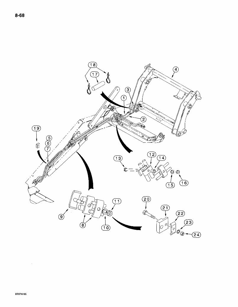
8-68
© ®
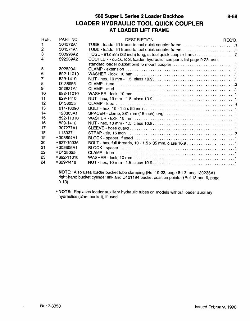
REF. PART NO. 1 304572A1 2 304574A1 3 300996A2 4 292969A2
5 302820A1 6 892-11010 7 829-1410 8 D138055 9 302821A1 10 892-11010 11 829-1410 12 D138055 13 814-10090 14 120303A1 15 892-11010 16 829-1410 17 307277A1 18 LI 8337 19 *303804A1 20 * 627-10035 21 *303806A1 22 *D138055 23 * 892-11010 24 * 829-1410
580 Super L Series 2 Loader Backhoe LOADER HYDRAULIC TOOL QUICK COUPLER
AT LOADER LIFT FRAME
DESCRIPTION TUBE - loader lift frame to tool quick coupler frame TUBE - loader lift frame to tool quick coupler frame HOSE - 812 mm (32 inch) long, at tool quick coupler frame COUPLER - quick, tool, loader, hydraulic, see parts list page 9-23, use standard loader bucket pins to mount coupler CLAMP - extension WASHER-lock, 10mm NUT - hex, 10 mm -1.5, class 10.9 CLAMP-tube CLAMP-stud WASHER - lock, 10 mm NUT - hex, 10 mm - 1.5, class 10.9 CLAMP - tube BOLT - hex, 10 -1.5 x 90 mm SPACER - clamp, 381 mm (15 inch) long WASHER-lock, 10mm NUT - hex, 10 mm - 1.5, class 10.9 SLEEVE - hose guard STRAP-tie, 15 inch BLOCK - spacer, if used BOLT - hex, full threads, 10 -1.5 x 35 mm, class 10.9 BLOCK - spacer CLAMP-tube WASHER-lock, 10 mm NUT - hex, 10 mm -1.5, class 10.9
8-69
REQ'D.
NOTE: Also uses loader bucket tube clamping (Ref 19-23, page 8-13) and 139235A1 right-hand bucket cylinder link and D121194 bucket position pointer (Ref 13 and 6, page 9-13).
* NOTE: Replaces loader auxiliary hydraulic tubes on models without loader auxiliary hydraulics (clam bucket), if used.
Bur 7-3350 Issued February, 1998
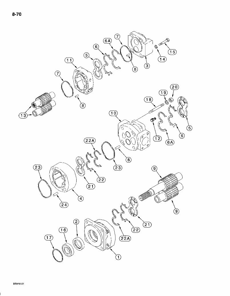
8-70
580 Super L Series 2 Loader Backhoe EQUIPMENT HYDRAULIC PUMP
8-71
REF. PART NO. -257954A1
1 NSS 2 + L32318-3 NSS 4 142733A1 5 +111594A1 6 +293926A1 6A + 293925A1, 7 +111596A1 8 111597A1 9 NSS 10 NSS 11 • 142735A1 12 111593A1 13 NSS 14 111588A1 15 326-852 16 S88754 17 S88756 18 111583A1 19 19-488 20 429-1010 21 . + l i l589A1 22 ' , +293927A1 22A +293928A1 23 +111592A1 24 W16323
DESCRIPTION REQ'D. PUMP ASSEMBLY - hydraulic equipment, 17 teeth shaft gear set, used with 257948A1 flex coupling on page 8-3
COVER - shaft end SEAL - shaft COVER - closed end HOUSING - gear, shaft end PLATE - thrust, closed end 2 SEAL - used with 293925A1 backup seal 2 SEAL - backup, used with 293926A1 seal 2 SEAL - square ring, 3-1/4 |D x 3/32 inch wide, housing, closed end 2 PIN-dowel, 1/4 X 1/16 inch, closed end, gear housing . .4 SET - gear, shaft end, 17 teeth, 1-1/8 inch diameter shaft spline 1 HOUSING - center, with-ports 1 HOUSING - gear, closed end, pump 1 SHAFT - connecting 1 SET - gear, closed end 1 WASHER - flat, special, 17/32 x -15/16 x 3/16 inch 4 BOLT - hex, 1/2 NC x 3-1/4 inch, grade 8 4 BEARING - ball, sealed . . . . . . . i 1 RING - snap, retaining, spring lock 1 STUD- 4 WASHER-flat. 4 NUT - hex, 5/8 inch NC, grade 8 4 PLATE - thrust, shaft end . . . 2 SEAL- used with 293928A1 backup seal .2 SEAL - backup, used with 293927A1 seal .2 SEAL - square ring, 4-31/64 ID x 1/8 inch wide, shaft end 2 PIN - dowel, shaft end 4
-293924A1 KIT - seal, includes above items niarked with a -i- 1
Bur 7-3350 Issued February, 1998
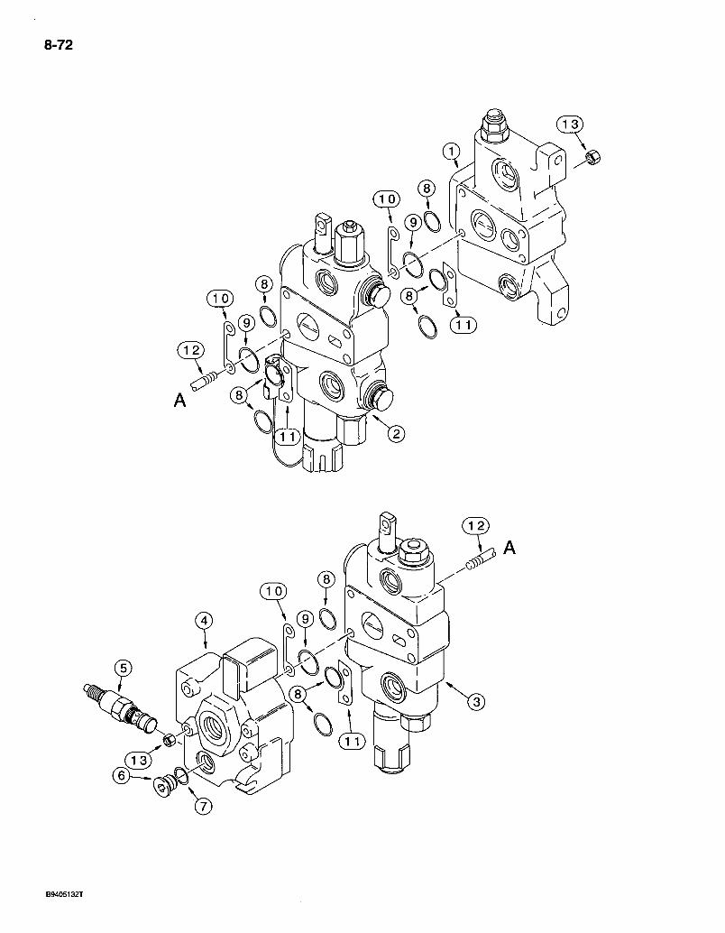
8-72
U A
B9405132T
REF. PART NO. ' 302965A1
1 .121736A2
2 302964A1
3 113793A4 4 132004A2 5 129842A2
6 218-5207
7 237-6004 8 * 238-6119 9 * 238-6127 10 G107251 11 G33965 12 G108870 13 425-106
*1346108C2
580 Super L Series 2 Loader Bacl<lioe 8-73! LOADER CONTROL VALVE
TWO SPOOL
DESCRIPTION REQ'D. VALVE ASSEMBLY - control, loader, two spool 1
SECTION ASSEMBLY - inlet, with pilot relief valve, parts list page 8-77 : .1 SECTION ASSEMBLY-bucket, with magnetic detent and circuit relief valve, parts list page 8-79 1 SECTION ASSEMBLY - lift, with manual detent, parts list page 8-81 1 SECTION ASSEMBLY - valve, outlet, parts list page 8-83 1 VALVE ASSEMBLY - main relief, components, parts are not serviced separately, for service of external seals order G110098 seal kit 1 PLUG - hex socket, 7/16-20 inch 0-ring boss, outlet section diagnostic port 1
0-RING - 23/64 ID x 5/64 inch wide 1 0-RING -15/16 ID X 3/32 inch wide, section ports, small .9 0-RING - 1-7/16.ID X 3/32 inch wide, section ports, large 3 SHIM - section, port side of control valve 3 SHIM - section, non-port side of control valve 3 STUD - tie, 3/8 NC x 9-3/4 inch .4 NUT - hex, 3/8 inch NC 8
KIT - seal, includes above itemsmarked with an asterisk, plus additional 0-rings not required for this application. 1
Bur 7-3350 Issued February, 1998
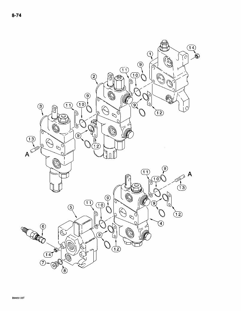
8-74

580 Super L Series 2 Loader Backhoe LOADER CONTROL VALVE
THREE SPOOL
8-75
REF. : PART NO. 302966A1
1 121736A2
2 302964A1
3 113793A4 4 113794A4 5 132004A2 6 129842A2
7 218-5207
8 237-6004 9 * 238-6119 10 * 238-6127 11 G107251 12 G33965 13 G108805 14 425-106
*'1346108C2
DESCRIPTION REO'D. VALVE ASSEMBLY - loader control, three-spool 1
SECTION ASSEMBLY - inlet, with pilot relief valve, parts list page 8-77 1 SECTION ASSEMBLY - bucket, with magnetic detent and circuit relief valve, parts list page 8-79 1 SECTION ASSEMBLY - lift, with manual detent, parts list page 8-81 1 SECTION ASSEMBLY - clam, all valves, parts list page 8-85 1 SECTION ASSEMBLY - outlet, parts list page 8-83 1 VALVE ASSEMBLY - main relief, component parts are hot serviced separately, forservice of external seals order G110098 seal kit 1 PLUG - hex socket, 7/16-20 inch O-ring boss, outlet section diagnostic port 1
0-RlNG - 23/64 ID x 5/64 inch wide 1 O-RING - 15/16 ID x 3/32 inch wide, section ports, small . . . ; 12 O-RING -1-7/16 ID X 3/32 inch wide, section ports, large 4 SHIM - section, port side of control valve 4 SHIM - section, non-port side of control valve 4 STUD - tie, 3/8 NC x 11-3/4 inch 4 NUT - hex, 3/8 inch NC . . 8
KIT - seal, includes above items marked with an asterisk, plus additional 0-rings not required for this application . .1
Bur 7-3350 Issued February, 1998

8-76
BT97N194
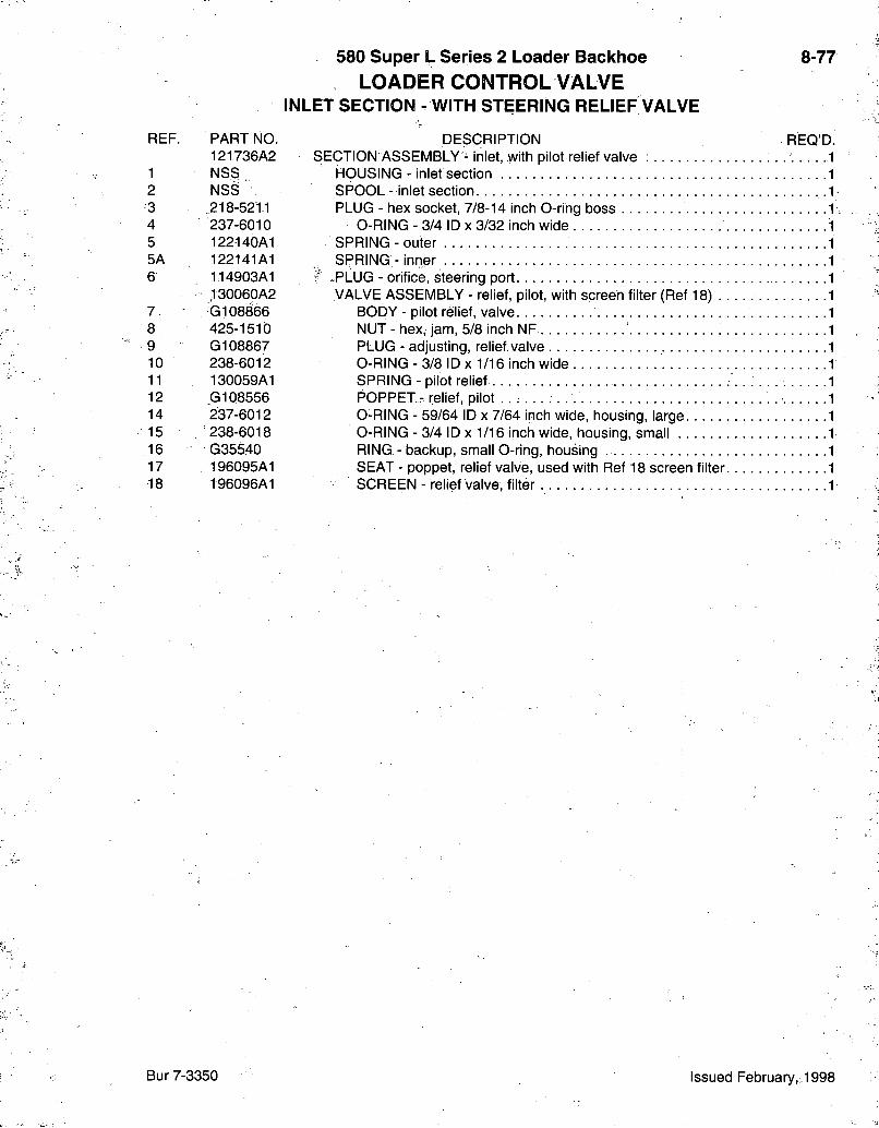
REF. PART NO. 121736A2
1 NS.S 2 NSS 3 218-521.1 4 237-6010 5 122140A1 5A 122141A1 6 114903A1
130060A2 7. G108866 8 425-1510 9 G108867 10 238-6012 11 130059A1 12 _G108556 14 237-6012 15 '238-6018 16 G35540 17 196095A1 18 196096A1
580 Super L Series 2 Loader Backhoe LOADER CONTROL VALVE
INLET SECTION - WITH STEERING RELIEF VALVE
DESCRIPTION SECTION ASSEMBLY - inlet, with pilot relief valve ;
HOUSING - inlet section SPOOL - inlet section . PLUG - hex socket, 7/8-14 inch 0-ring boss
0 - R I N G - 3/4 ID X 3/32 inch wide - SPRING - outer
SPRING - inner - P L U G - orifice, steering port VALVE ASSEMBLY - relief, pilot, with screen filter (Ref 18 ) . .
BODY - pilot relief, valve NUT - hex, jam, 5/8 inch NF PLUG - adjusting, relief valve 0-RING - 3/8 ID X 1/16 inch wide SPRING - pilot relief POPPET - relief, pilot 0-RING - 59/64 ID x 7/64 inch wide, housing, large 0-RlNG - 3/4 ID X 1/16 inch wide, housing, small RING - backup, small 0-ring, housing SEAT - poppet, relief valve, used with Ref 18 screen filter. SCREEN - relief valve, filter
8-77
REQ'D.
Bur 7-3350 Issued February,; 1998
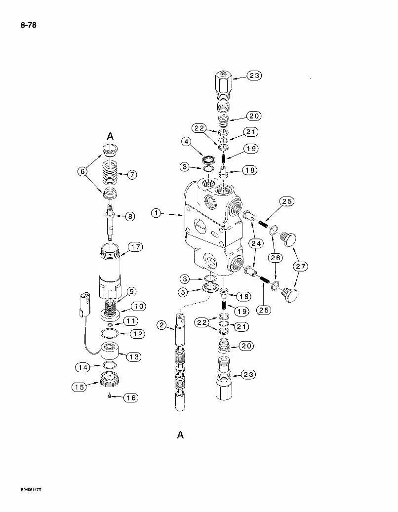
8-78
J_4
( 3 ) — O
TT9) ( 2 5 )

580 Super L Series 2 Loader Backhoe LOADER CONTROL VALVE
BUCKET SECTION - WITH MAGNETIC DETENT AND CIRCUIT RELIEF VALVE
8-79
REF. PART NO. 302964A1
1 NSS 2 NSS 3 *1994608C1 4 *65457C1 5 G102711 6 G33075 7 302326A1
8 118318A1 9 G107447 10 G109295 11 100-1125 12 238-5127 13 120148A2 14 238-5120 15 122330A1 16 G107780 17 113787A3
134621903 18 302246A1 19 134617501 20 1343708C1 21 * 238-6016 22 *G103862 23 G109391
129735A2 24 302247A1 25 G34458 26 237-6010 27 129699A1
DESORIPTION REQ'D. SEOTION ASSEMBLY - bucket, with magnetic detent and circuit relief valves
HOUSING - bucket section SPOOL - bucket section O-RING - spool SEAL - oil, spool RETAINER - 0-ring SEAT - centering spring SPRING - centering, spool, used in 113786A4, 113786A5 or 113786A6 sections SHAFT - magnetic detent SPRING - detent washer WASHER - detent RING - external retaining. No. 25, washer retaining O-RING -1-7/16 ID X 3/32 inch wide MAGNET - with connector O-RING - 1 ID X 3/32 inch wide PLUG - magnetic detent PLUG - check, magnetic detent HOUSING - magnetic detent VALVE ASSEMBLY - load check, hollow poppet pin
POPPET - hollow poppet pin with orifice SPRING - load check PLUG - load check O-RING - 5/8 ID X 1/16 inch wide RING - backup, plug O-ring 2
VALVE ASSEMBLY - circuit relief, 3200 psi, one piece cap, used in production, parts list page 8-87, order G109449 circuit relief valve kit for service, see page 8-99 for kit 2 VALVE ASSEMBLY - anticavitation .
POPPET - anticavitation SPRING - anticavitation O-RING - 3/4 ID X 3/32 inch wide PLUG - anticavitation
.2
.1
.1
.1
.1
• 1346105C2 KIT - seal, includes above items marked with an asterisk, plus additional 0-rings not required for this application
Bur 7-3350 Issued February, 1998
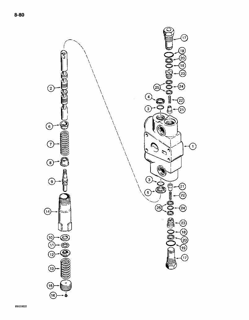
8-80
U5)
o—®
\
1-^
B902082S
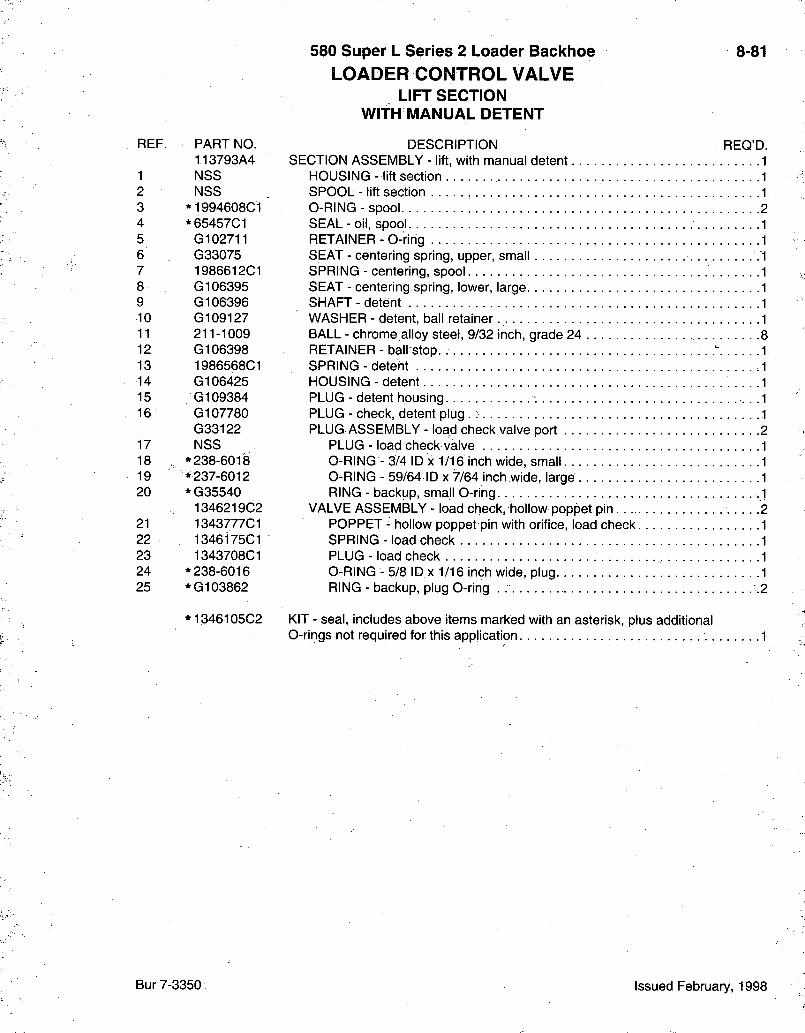
580 Super L Series 2 Loader Backhoe LOADER CONTROL VALVE
LIFT SECTION WITH MANUAL DETENT
8-81
REF. PART NO. 113793A4
1 NSS 2 NSS 3 *1994608C1 4 *65457C1 5 G102711 6 G33075 7 1986612C1 8 G106395 9 G106396 10 G109127 11 211-1009 12 G106398 13 1986568C1 14 G106425 15 G109384 16 G107780
G33122 17 NSS 18 * 238-6018 19 * 237-6012 20 *G35540
1346219C2 21 1343777C1 22 1346i75C1 23 1343708C1 24 * 238-6016 25 *G103862
DESCRIPTION SECTION ASSEMBLY - lift, with manual detent
HOUSING - lift section SPOOL - lift section O-RING - spool SEAL - oil, spool. RETAINER - 0-ring SEAT - centering spring, upper, small SPRING - centering, spool SEAT - centering spring, lower, large. SHAFT - detent WASHER - detent, ball retainer BALL - chrome alloy steel, 9/32 inch, grade 24 RETAINER - ball stop. SPRING - detent HOUSING - detent PLUG - detent housing PLUG - check, detent plug . PLUG ASSEMBLY - load check valve port
PLUG - load check valve O-RING - 3/4 ID X 1/16 inch wide, small O-RING - 59/64 ID x 7/64 inch wide, large RING - backup, small O-ring
VALVE ASSEMBLY - load check, hollow poppet pin POPPET - hollow poppet pin with orifice, load check. SPRING - load check PLUG - load check O-RING - 5/8 ID X 1/16 inch wide, plug RING - backup, plug O-ring .
REQ'D.
*1346105C2 KIT - seal, includes above items marked with an asterisk, plus additional O-rings not required for this application
Bur 7-3350 Issued February, 1998
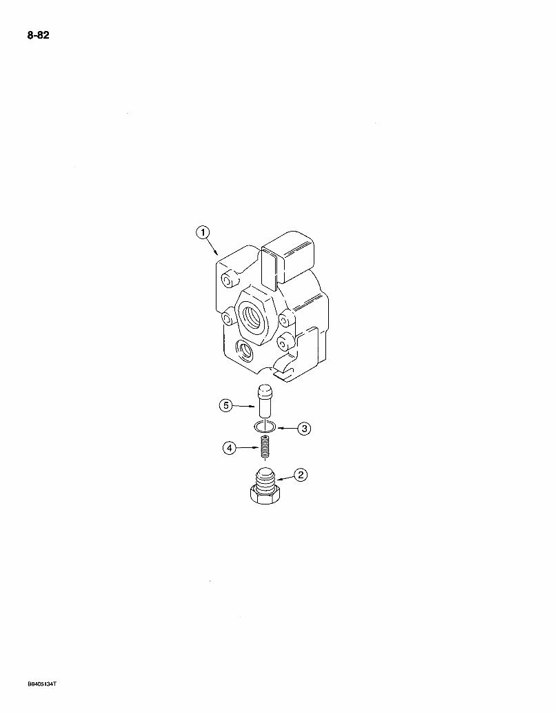
8-82
O—(D
B9405134T
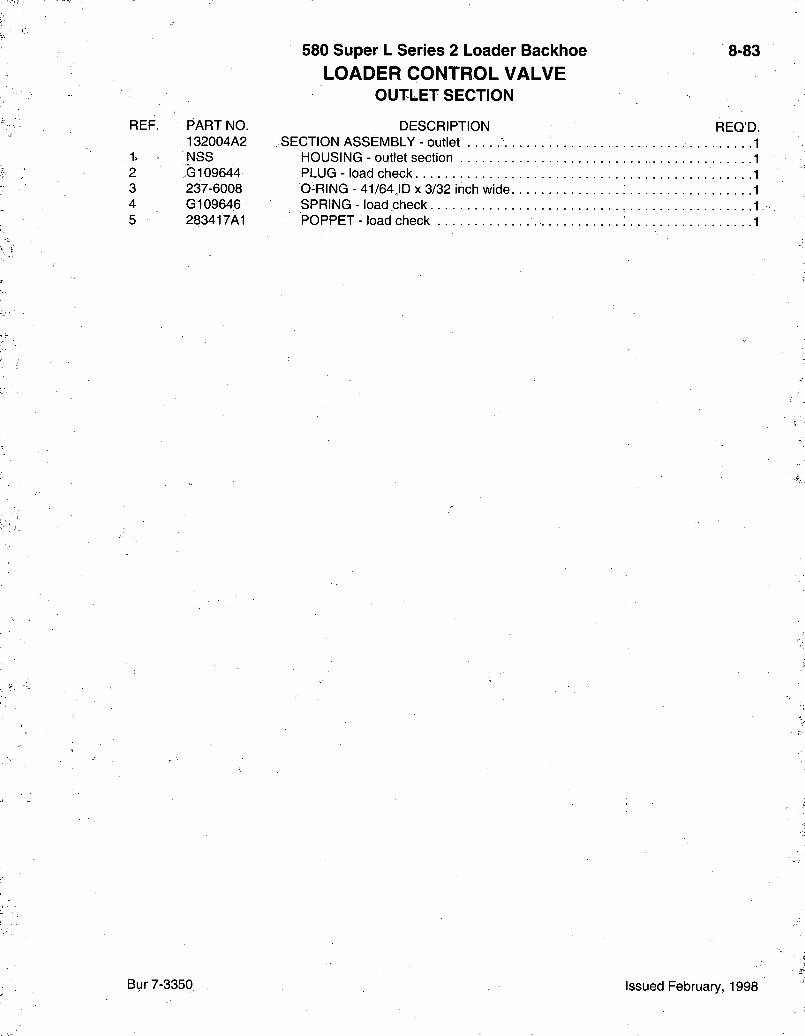
580 Super L Series 2 Loader Backhoe LOADER CONTROL VALVE
OUTLET SECTION
8-83
REF. PART NO. DESCRIPTION 132004A2 . SECTION ASSEMBLY - outlet
1, NSS HOUSING - outlet section 2 G109644 PLUG - load check 3 237-6008 O-RING - 41/64JD x 3/32 inch wide. 4 G109646 SPRING - load check 5 283417A1 POPPET - load check
REQ'D.
Bur 7-3350 Issued February, 1998
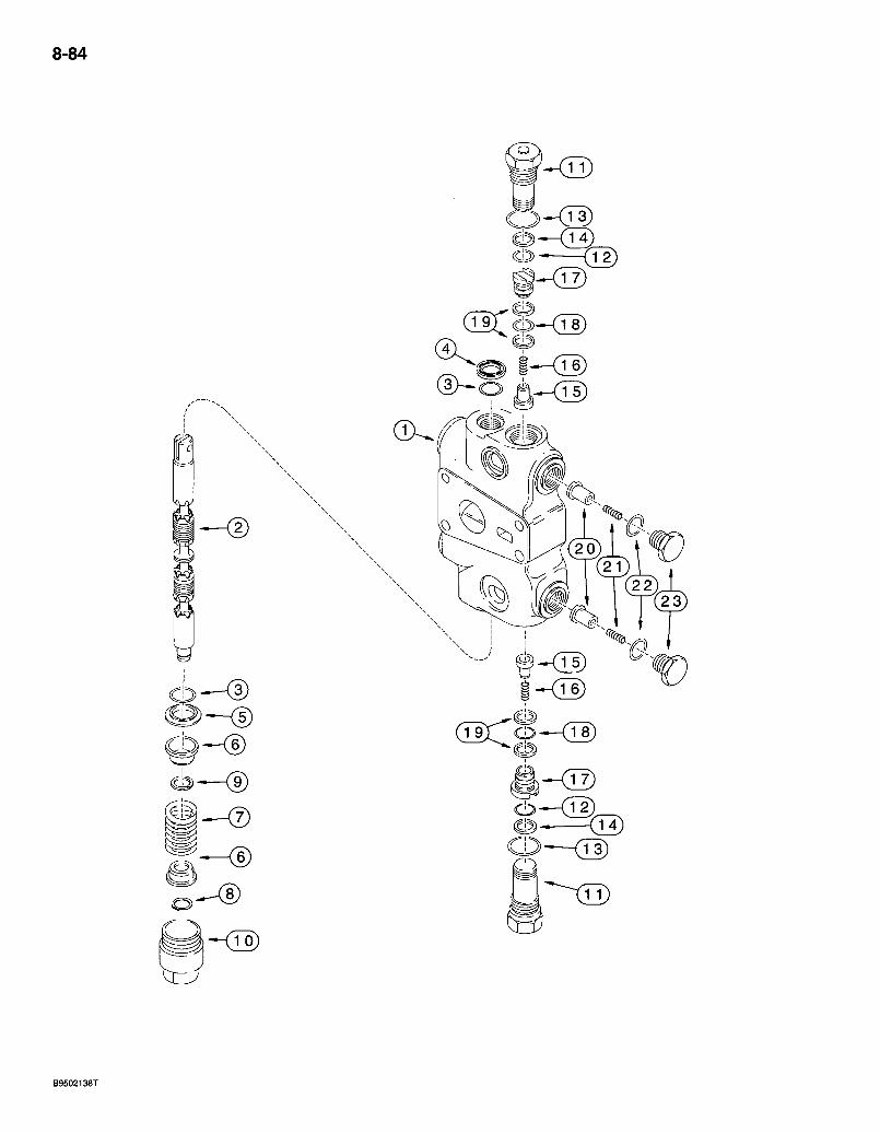
8-84
(I>^o A-^<i5)
Cl>—<12)
B9502138T
580 Super L Series 2 Loader Backhoe LOADER CONTROL VALVE
CLAIVI SECTION
8-85
REF. PART NO. 113794A4
1 NSS 2 NSS 3 *1994608C1 4 *65457C1 5 G102711 6 G33075 7 1994596C1
8 100-1647 9 G106410 10 G33080
G33122 11 NSS 12 * 238-6018 13 * 237-6012 14 *G35540
1346219C2 15 1343777C1 16 1346175C1 17 1343708C1 18 * 238-6016 19 *G103862
129735A1 20 129698A1 21 G34458 22 237-6010 23 129699A1
*1346105C2
DESCRIPTION SECTION ASSEMBLY - clam, three spool valve
HOUSING - clam section SPOOL - clam section O-RING - spool SEAL - oil, spool RETAINER - 0-ring SEAT - centering spring SPRING - centering, purple, 2-15/16 inch free length, spool, clam section RING - heavy external retaining. No. 47 SPACER - screw CAP - centering spring, spool end, lower PLUG ASSEMBLY - load check valve port
PLUG - load check valve O-RING - 3/4 ID X 1/16 inch wide, small O-RING - 59/64 ID x 7/64 inch wide, large RING - backup, small O-ring
VALVE ASSEMBLY - load check, hollow poppet pin POPPET - hollow poppet pin with orifice, load check SPRING - load check PLUG - load check O-RING - 5/8 ID X 1/16 inch wide, plug RING - backup, plug O-ring
VALVE ASSEMBLY - anticavitation POPPET - anticavitation SPRING - anticavitation O-RING - 3/4 ID X 3/32 inch wide PLUG - anticavitation
REQ'D.
KIT - seal, includes above items marked with an asterisk, plus additional 0-rings not required for this application
Bur 7-3350 Issued February, 1998
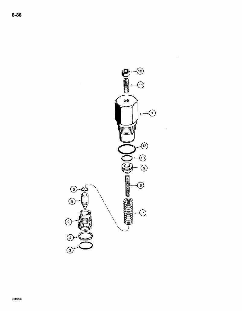
8-86
0 - ®
861823S
REF. PART NO. 'G109391
1 NSS 2 NSS 3 238-6018 4 G35540 5 NSS 6 NSS 7 NSS 8 NSS 9 NSS 10. NSS 11 484-43116 12 425-155 13 237-6012
580 Super L Series 2 Loader Backhoe LOADER CONTROL VALVE
BUCKET SECTION CIRCUIT RELIEF VALVE
8-87
REQ'D. DESCRIPTION VALVE ASSEMBLY - circuit relief, 3200 psi, one piece cap, used in production, order G109449 kit for service 2
HOUSING - circuit relief valve : SEAT - circuit relief valve O-RING - 3/4 ID X 1/16 inch wide RING - backup POPPET - circuit relief valve. O-RING - poppet SPRING - relief, outer SPRING - relief, inner. PISTON - circuit relief valve O-RING - piston SCREW - set, hex socket headless, 5/16 NF x 1 inch, oval point . NUT - hex, jam, 5/16 inch NF. ." . O-RING - 59/64 ID x 7/64 inch wide
*G109449 KIT - service, for G109391 circuit relief valve, kit includes an instruction sheet and G109447 circuit relief valve (items 1-13) which is the same as G109391 except with a different pressure setting
N O T E : The pressure setting of the repair circuit relief valve is not preset for this application. Adjust the setting according.to the instructions sent with the repair valve or according to the service manual.
Bur 7-3350 Issued February, 1998
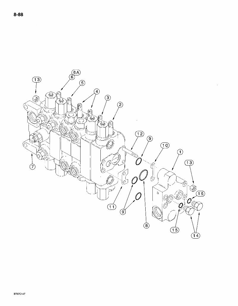
8-88
BT97C147
580 Super L Series 2 Loader Backhoe BACKHOE CONTROL VALVES
IVIODELS WITHOUT EXTENDABLE DIPPER WITHOUT AUXILIARY HYDRAULICS
8-89
REF. PART NO. 243135A1 243136A1
1 113248A2 2 129864A4 3 13661 OAS 4 253989A2
5 144321A5 6 241088A3
6A 243145A3
7 1542829C1 8 * 238-6127 9 * 238-6119 10 G107251 11 G33965 12 G108900 13 425-106 14 218-5157 15 237-6010
*1346107C2
DESCRIPTION REQ'D. VALVE ASSEMBLY - backhoe control, 6 spool, foot swing, if used 1 VALVE ASSEMBLY - backhoe control, 6 spool, hand swing, if used 1
SECTION ASSEMBLY - outlet, parts list page 8-97 1 SECTION ASSEMBLY - bucket, parts list page 8-99 1 SECTION ASSEMBLY - dipper, parts list page 8-101 1 SECTION ASSEMBLY - stabilizer, left-hand and right-hand, parts list page 8-103 2 SECTION ASSEMBLY - boom, parts list pages 8-105 and 8-107 1 SECTION ASSEMBLY - swing, foot swing control valve, parts list pages 8-109 and 8-111 1 SECTION ASSEMBLY - swing, hand swing control valve, parts list pages 8-109 and 8-111 1 SECTION ASSEMBLY - inlet, parts list page 8-97 1 O-RING -1-7/16 ID X 3/32 inch wide, section ports, large 7 O-RING -15/16 ID X 3/32 inch wide, section ports, small 21 SHIM - section 7 SHIM - section 7 STUD - tie, 3/8 NC x 16-15/16 inch 4 NUT - hex, 3/8 inch NC 8 PLUG - hex, 7/8-14 inch O-ring boss, outlet section 2
O-RING - 3/4 ID x 3/32 inch wide 1
KIT - seal, includes above items marked with an asterisk, plus additional O-rings not required in this application 1
Bur 7-3350 Issued February, 1998
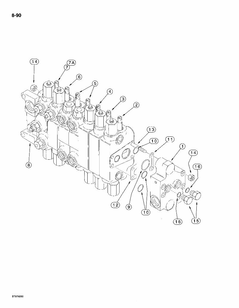
8-90
REF. PART NO. 243139A2 243141A2
1 113248A2 2 294198A1
3: 129864A4 4 136610A5 5 253989A2
6 144321A5 7 241088A3
7A 243145A3-
8 1542829C1 9 * 238-6127 10 * 238-6119 11 . G107251 12 033965, 13 G108899 14 425-106 15 . 218-5157 16 237-6010
*1346107C2
580 Super L Series 2 Loader Backhoe 8-91 BACKHOE CONTROL VALVES
MODELS WITHOUT EXTENDABLE DIPPER WITH AUXILIARY HYDRAULICS
DESCRIPTION REQ'D. VALVE ASSEMBLY - backhoe control, 7 spool, foot swing .1 VALVE ASSEMBLY - backhoe control, 7 spool, hand swing 1
SECTION ASSEMBLY - outlet, parts list page 8-97 . . : .1 SECTION ASSEMBLY - options, auxiliary hydraulics, parts list page 8-115 -1 SECTION ASSEMBLY - bucket, parts list page 8-99 1 SECTION ASSEMBLY - dipper, parts list page 8-101 . J 1 SECTION ASSEMBLY - stabilizer, left-hand and right-hand, parts list page 8-103 2 SECTION ASSEMBLY - boom, parts list pages 8-105 and 8-107 1 SECTION ASSEMBLY - swing, foot swing control valve, parts list pages 8-109 and 8-111 1
. SECTION ASSEMBLY - swing, hand swing control valve; parts list pages 8-109 and 8-111 1 SECTION ASSEMBLY - inlet, parts list page 8-97. . . : 1 O-RING -1-7/16 ID X 3/32 inch wide, section ports, large 8 O-RING - 15/16 ID X 3/32 inch wide, section ports, small 24 SHIM - section . 8 SHIM - section 8 STUD - tie, 3/8 NC x 18-15/16 inch 4 NUT - hex, 3/8 inch NC 8 PLUG - hex, 7/8-14 inch O-ring boss 2
O-RING - 3/41D X 3/32 inch wide 1
KIT - seal, includes above items marked with an asterisk, plus additional 0-rings not required for this application 1
Bur 7-3350 Issued February, 1998
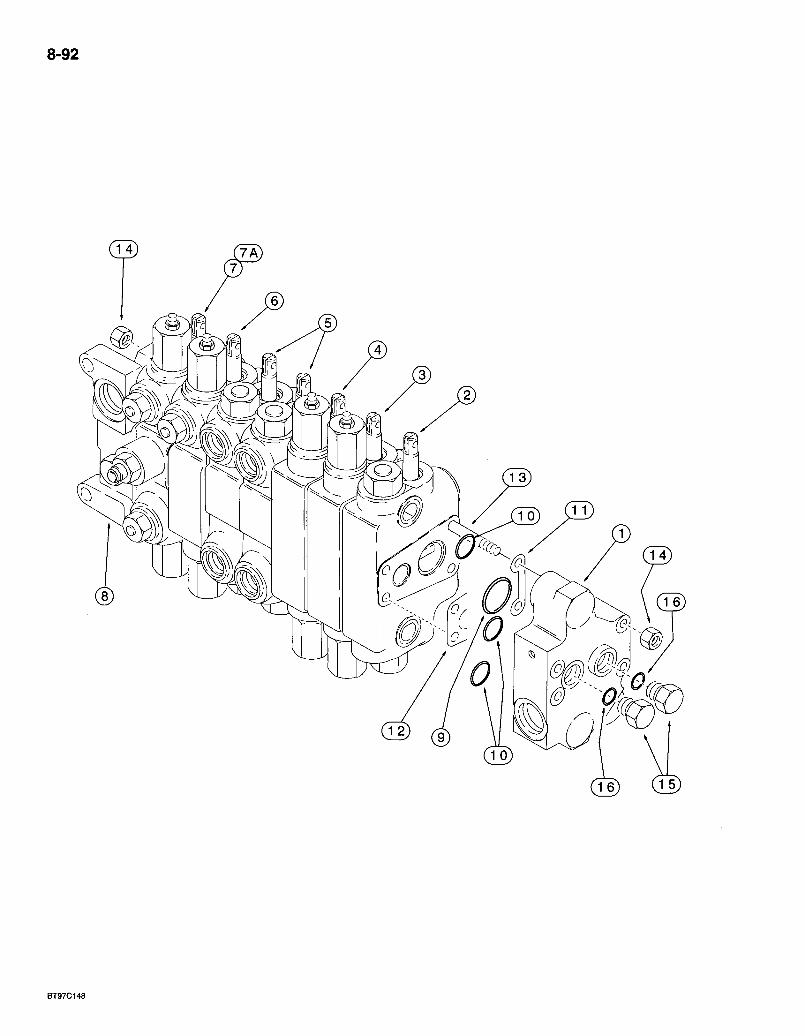
8-92
BT97C148
REF. PART NO. 243137A1 243138A1
1 . 113248A2 2 144324A4 3 129864A4 4 . 13661 OAS 5 253989A2
6 144321A5 7 241088A3
7A 243145A3
8 1542829C1 9 * 238-6127 10 * 238-6119 11 G107251 12 G33965 13 G108899 14 425-106 15 218-5157 16 237-6010
*1346107C2
580 Super L Series 2 Loader Backhoe 8-93 BACKHOE CONTROL VALVES
MODELS WITH EXTENDABLE DIPPER WITHOUT AUXILIARY HYDRAULICS
DESCRIPTION REQ'D. VALVE ASSEMBLY - backhoe control, 7 spool, foot swing, if used .1 VALVE ASSEMBLY - backhoe control, 7 spool, hand swing, if used 1
SECTION ASSEMBLY - outlet, parts list page 8-97 , 1 SECTION ASSEMBLY - dipper extension, parts list page 8-113 1 SECTION ASSEMBLY - bucket, parts list page 8-99. 1 SECTION ASSEMBLY - dipper, parts list page 8-101 1 SECTION ASSEMBLY - stabilizer, left-hand and rightvhand, parts list page 8-103 2 SECTION ASSEMBLY - boom, parts list pages 8-105 and 8-107 1 SECTION ASSEMBLY - swing, foot swing control valve, parts list pages 8-109 and 8-111. 1 SECTION ASSEMBLY - swing, hand swing control valve, parts list pages 8-109 and 8-111 1 SECTION ASSEMBLY - inlet, parts list page 8-97 1 O-RING - 1-7/16 ID X 3/32 inch wide, section ports, large . .8 0-RING -15/16 ID X 3/32 inch.wide, section ports, small 24 SHIM -section .8 SHIM - section 8 STUD - tie, 3/8 NC x 18-15/16 inch 4 NUT - hex, 3/8 inch NC 8 PLUG - hex, 7/8-14 inch 0-ring boss.. 2
O-RING - 3/4 ID X 3/32 inch wide 1
KIT - seal, includes above items marked with an asterisk, plus additional 0-rings not required for this application .1
Bur 7-3350 Issued February, 1998
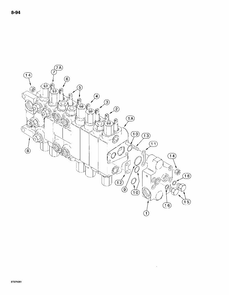
8-94
BT97N061
580 Super L Series 2 Loader Backhoe BACKHOE CONTROL VALVES
MODELS WITH EXTENDABLE DIPPER WITH AUXILIARY HYDRAULICS
8-95
REF. PART NO. 243142A2 243143A2
1 113248A2 1A 294198A1
2 . 144324A4 3 129864A4 4 13661 OAS 5 253989A2
6 144321A5 7 ,241088A3
7A 243145A3
8 ; 1542829C1 9 * 238-6127 10 * 238-6119 11 , G107251 12 ' G33965 13 229684A1 14 ,425-106 15 218-5157;, 16 237-6010
*1346107C2
DESCRIPTION REQ'D. VALVE ASSEMBLY - backhoe control, 8 spool, foot swing 1 VALVE ASSEMBLY - backhoe control, 8 spool, hand swing 1
SECTION ASSEMBLY - outlet, parts list page 8-97 1 SECTION ASSEMBLY - options, auxiliary hydraulics, parts list page 8-115 1 SECTION ASSEMBLY - dipper extension, parts list page 8-113 1 SECTION ASSEMBLY - bucket, parts list page 8-99 1 SECTION ASSEMBLY - dipper, parts list page 8-101 1 SECTION ASSEMBLY - stabilizer, left-hand and right-hand, parts list page 8-103 2 SECTION ASSEMBLY - boom, parts list pages 8-105 and 8-107 1 SECTION ASSEMBLY - swing, foot swing control valve, parts list pages 8-109 and 8-111 1 SECTION ASSEMBLY - swing, hand swing control valve, parts list pages 8-109 and 8-111 1 SECTION ASSEMBLY - inlet, parts list page 8-97 1 O-RING -1-7/16 ID X 3/32 inch wide, section ports, large ;9 0-RING -15/16 ID X 3/32 inch wide, section ports, small 27 SHIM - section 9 SHIM-section 9 STUD-tie . .4 NUT - hex, 3/8 inch NC 8 PLUG - hex, 7/8-14 inch 0-ring boss .2
O-RING - 3/4 ID x 3/32 inch wide 1
KIT - seal, includes above items marked with an asterisk, plus additional 0-rings not required for this application .1
Bur 7-3350 Issued February, 1998
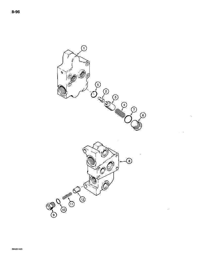
8-96
B9405145S
REF. PART NO.
580 Super L Series 2 Loader Backhoe BACKHOE CONTROL VALVE
INLET AND OUTLET SECTIONS
DESCRIPTION OUTLET SECTION
8-97
REQ'D.
1 2 3 4 5 6 7
8
9 10 11 12
113248A2 NSS G108902 257387A1 G33112 238-5118 218-5213 237-6014
154282901 NSS 134622102 G34937 237-6010 G34458 278735A1
SEOTION ASSEMBLY - outlet MANIFOLD - section body PISTON - regeneration sensing SPOOL - regeneration SPRING - regeneration spool. 0-RING - 7/8 ID X 3/32 inch wide PLUG - hex socket, 1-3/16-12 inch 0-ring boss
0-RING -1-3/64 ID x 7/64 inch wide
INLET SECTION
SECTION ASSEMBLY - inlet. MANIFOLD - section body . VALVE ASSEMBLY - anticavitation (order items 9-12)
PLUG - check valve 0-RING - 3/4 ID X 3/32 inch wide SPRING - check valve POPPET - check valve .
Bur 7-3350 Issued February, 1998
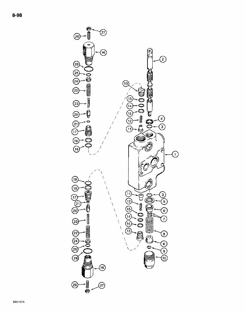
8-98
B921151S
580 Super L Series 2 Loader Backhoe BACKHOE CONTROL VALVE
BUCKET SECTION
8-99
REF. PART NO. 129864A4
1 " NSS 2 NSS. 3 *1994608C1 4 *65457C1 5 G102711 6 G33075 7 , G106410 8 , 1994596C1 9 .100-1647 10 G33080
134621903 11 302246A1 12 134617501 13 134370801 14 238-6016 15 = *G103862
**129861A1
16 NSS 17 NSS 18 * 238-6018 19 *G35540 20 • NSS 21 NSS 22 NSS 23 • NSS 24 NSS 25 NSS 26 484-431.16 27 •425-155
.28 * 237-6012
'1346105C2
**G110077
DESCRIPTION REQ'D. SECTION ASSEMBLY - bucket, with circuit relief valves 1
HOUSING - bucket section 1 SPOOL - bucket section 1 0-RING-spool • • • 2 SEAL - oil, spool .1 RETAINER -0-ring -1 SEAT - centering spring 2 SPACER-spool 2 SPRING - centering, purple, 2-15/16 inch free length, spool 1 RING - heavy external retaining, No. 47, spool end 1 CAP - centering spring, spool end . A VALVE ASSEMBLY - load check, hollow poppet pin 2
POPPET - hollow poppet pin with orifice, load check 1 SPRING - load check . 1 PLUG - load check 1 O-RING - 5/8 ID x 1/16 inch wide, plug 1 RING - backup, plug 0-ring 2
VALVE ASSEMBLY - circuit relief, bucket section, used in . production, order G110077 kit for service 2
HOUSING - circuit relief valve SEAT - circuit relief valve O-RING - 3/4 ID X 1/16 inch wide, circuit relief valve seat RING r backup, seat O-ring F^OPPET - circuit relief valve O-RING - poppet . . . . . SPRING - relief, outer SPRING - relief, inner PISTON - circuit relief valve O-RING -1/2 ID X 1/16 inch wide
' SCREW - set, hex socket headless, 5/16 NF x 1 inch, oval point NUT - hex, jam, 5/16 inch NF O-RING - 59/64 ID x 7/64 inch wide, housing.
KIT - seal, includes above items marked with an asterisk, plus additional O-rings not required for this application
KIT - service, for 129861A1 circuit relief valve, kit includes an instruction sheet and G110078 circuit relief valve (items 16-28) which is the same as 129861A1 except with a different pressure setting.. . ;
NOTE: The pressure setting of the repair circuit relief valve is not preset for this application. Adjust the setting according to the instructions sent with the repair valve or according to the service manual.
Bur 7-3350 Issued February, 1998
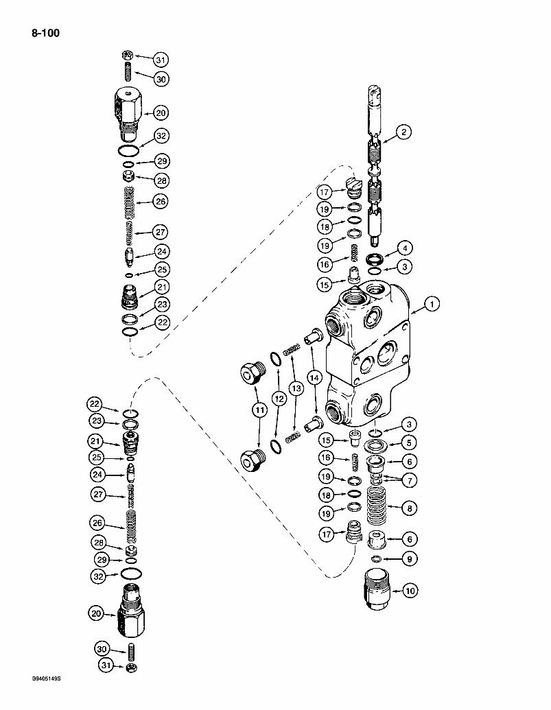
8-100
B9405149S
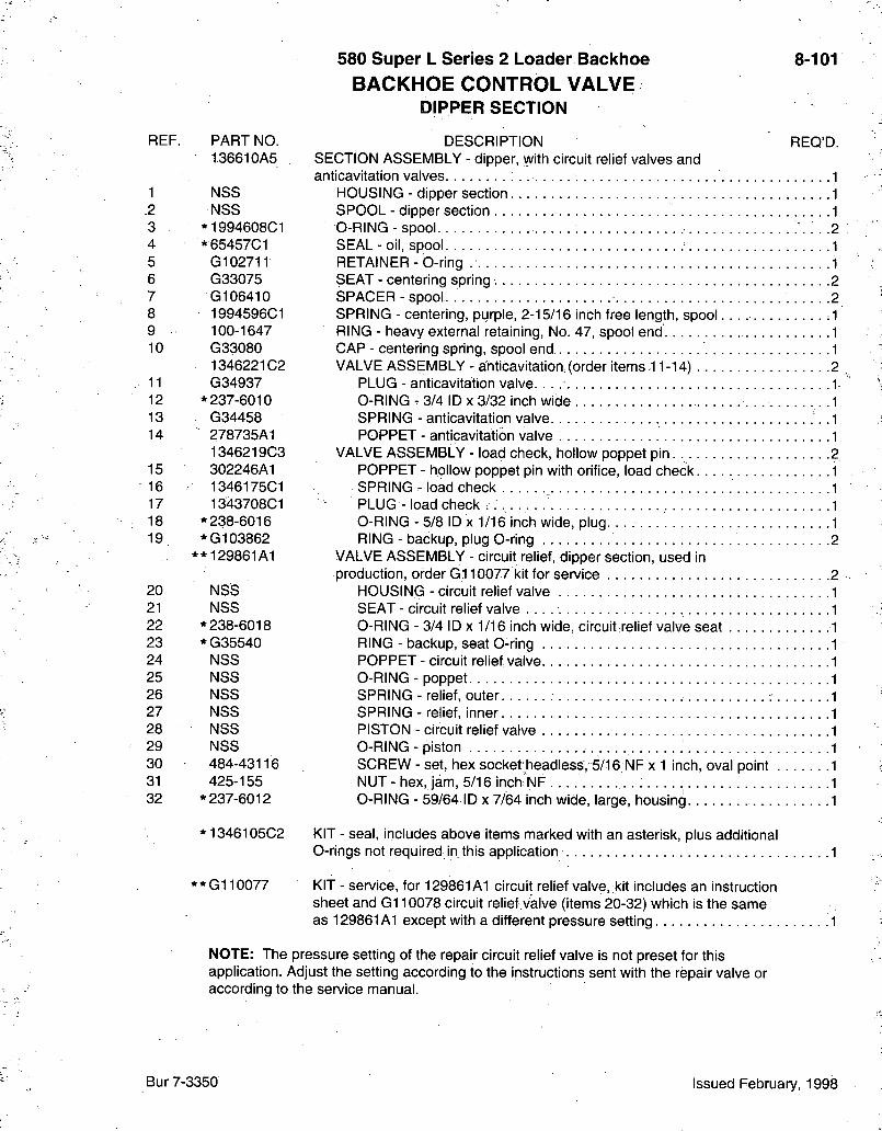
580 Super L Series 2 Loader Backhoe BACKHOE CONTROL VALVE
DIPPER SECTION
8-101
REF. PART NO. 136610A5
1 NSS .2 NSS 3 *1994608C1 4 *65457C1 5 G102711 6 G33075 7 G106410 8 1994596C1 9 100-1647 10 G33080
1346221C2 11 G34937 12 * 237-6010 13 G34458 14 278735A1
1346219C3 15 302246A1 16 1346175C1 17 1343708C1 18 * 238-6016 19 *G103862
**129861A1
20 NSS 21 NSS 22 * 238-6018 23 *G35540 24 NSS 25 NSS 26 NSS 27 NSS 28 NSS 29 NSS 30 484-43116 31 425-155 32 * 237-6012
*1346105C2
**G110077
DESCRIPTION REO'D. SECTION ASSEMBLY - dipper, with circuit relief valves and anticavitation valves
HOUSING - dipper section SPOOL - dipper section O-RING - spool. • SEAL - oil, spool RETAINER - 0-ring SEAT - centering spring SPACER - spool SPRING - centering, purple, 2-15/16 inch free length, spool RING - heavy external retaining, No. 47, spool end CAP - centering spring, spool end VALVE ASSEMBLY - anticavitation. (order items-11-14)
PLUG - anticavitation valve. O-RING - 3/4 ID X 3/32 inch wide SPRING - anticavitation valve POPPET - anticavitation valve
VALVE ASSEMBLY - load check, hollow poppet pin. POPPET - hollow poppet pin with orifice, load check SPRING - load check _ PLUG - load check O-RING - 5/8 ID X 1/16 inch wide, plug RING - backup, plug 0-ring 2
VALVE ASSEMBLY - circuit relief, dipper section, used in production, order G.110077 kit for service 2
HOUSING - circuit relief valve SEAT - circuit relief valve O-RING - 3/4 ID X 1/16 inch wide, circuit relief valve seat RING - backup, seat O-ring POPPET - circuit relief valve O-RING - poppet SPRING - relief, outer SPRING - relief, inner PISTON - circuit relief valve O-RING - piston . SCREW - set, hex socket headless, 5/16. NF x 1 inch, oval point NUT - hex, jam, 5/16 inch NF . . . . O-RING - 59/64 ID x 7/64 inch wide, large, housing
KIT - seal, includes above items marked with an asterisk, plus additional O-rings not required in this application
KIT - service, for 129861A1 circuit relief valve, kit includes an instruction sheet and G110078 circuit relief valve (items 20-32) which is the same as 129861A1 except with a different pressure setting
NOTE: The pressure setting of the repair circuit relief valve is not preset for this application. Adjust the setting according to the instructions sent with the repair valve or according to the service manual.
Bur 7-3350 Issued February, 1998
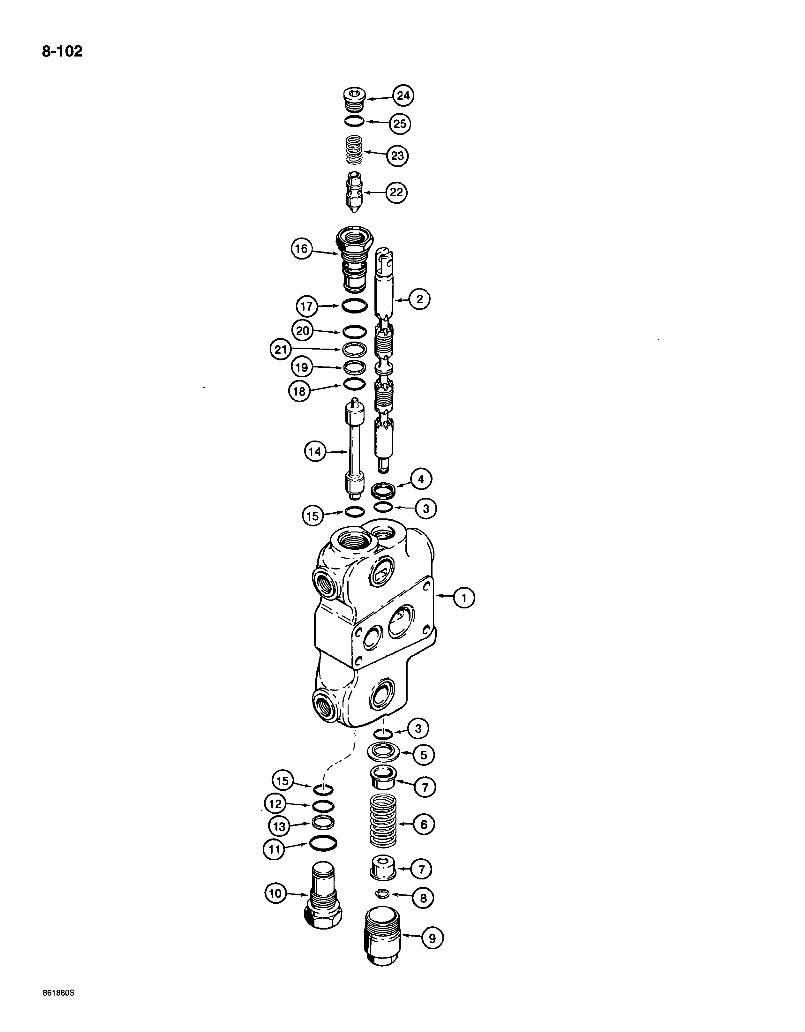
8-102
® — o
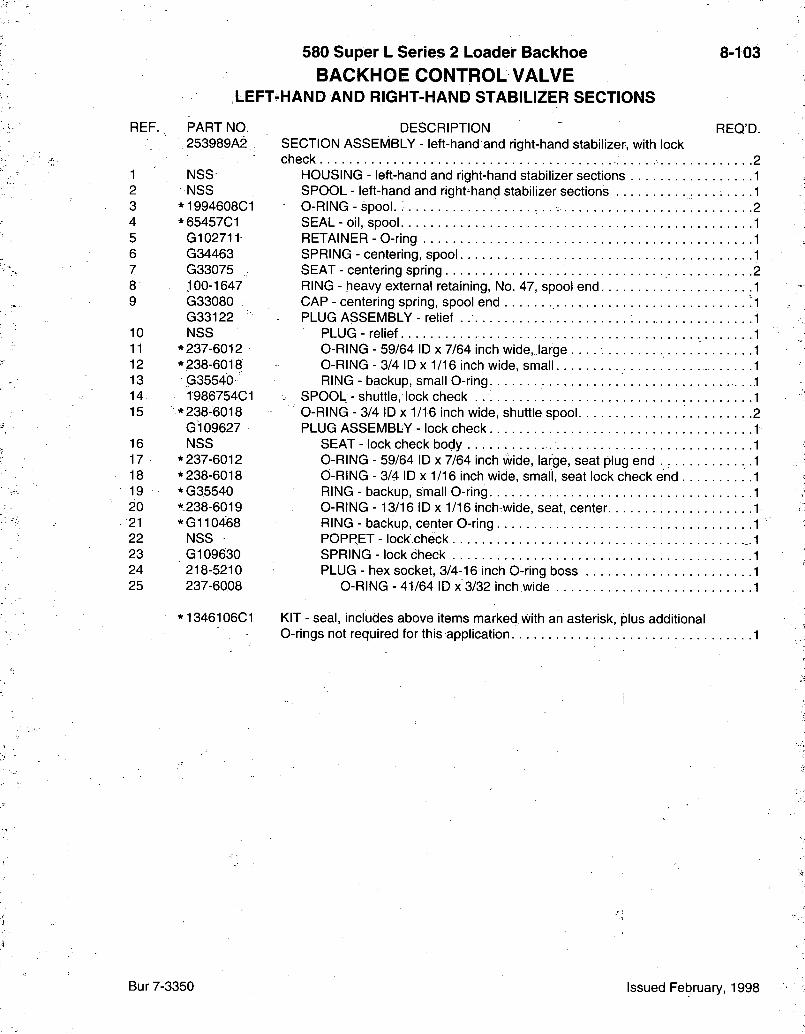
580 Super L Series 2 Loader Backhoe BACKHOE CONTROL VALVE
LEFT-HAND AND RIGHT-HAND STABILIZER SECTIONS
8-103
REF. PART NO. 253989A2
1 NSS 2 NSS 3 . *1994608C1 4 *65457C1 5 G102711 6 G34463 7 G33075 8 100-1647 9 G33080
G33122 10 NSS 11 * 237-6012 12 * 238-6018 13 G35540" 14 1986754C1 15 * 238-6018
G109627 16 NSS 17 * 237-6012 18 * 238-6018 19 *G35540 20 *238-6019 21 * Gi l 0468 22 NSS 23 G109630 24 218-5210 25 237-6008
*1346106C1
DESCRIPTION SECTION ASSEMBLY - left-hand and right-hand stabilizer,, with lock check. ;
HOUSING - left-hand and right-hand stabilizer sections SPOOL - left-hand and right-hand stabilizer sections 0-RING - spool. : SEAL - oil, spool RETAINER - 0-ring SPRING - centering, spool SEAT - centering spring RING - heavy external retaining, No. 47, spool end CAP - centering spring, spool end PLUG ASSEMBLY - relief .
PLUG - relief 0-RING - 59/64 ID x 7/64 inch wide, large 0-RING - 3/4 ID X 1/16 inch wide, small RING - backup, small O-ring
• SPOOL - shuttle, lock check 0-RING - 3/4 ID X 1/16 inch wide, shuttle spool PLUG ASSEMBLY - lock check
SEAT - lock check body 0-RING - 59/64 ID x 7/64 inch wide, large, seat plug end . . . . 0-RING - 3/4 ID X 1/16 inch wide, small, seat lock check end . RING - backup, small O-ring 0-RING -13/16 ID X 1/16 inch wide, seat, center RING - backup, center O-ring POPPET - lock check SPRING - lock check PLUG - hex socket, 3/4-16 inch O-ring boss
O-RING - 41/64 ID x 3/32 inch wide
REQ'D.
KIT - seal, includes above items marked with an asterisk, plus additional 0-rings not required for this application
Bur 7-3350 Issued February, 1998

8-104
^ — = ^ ^—^
\ / \ /
1 - ^
B9405135S
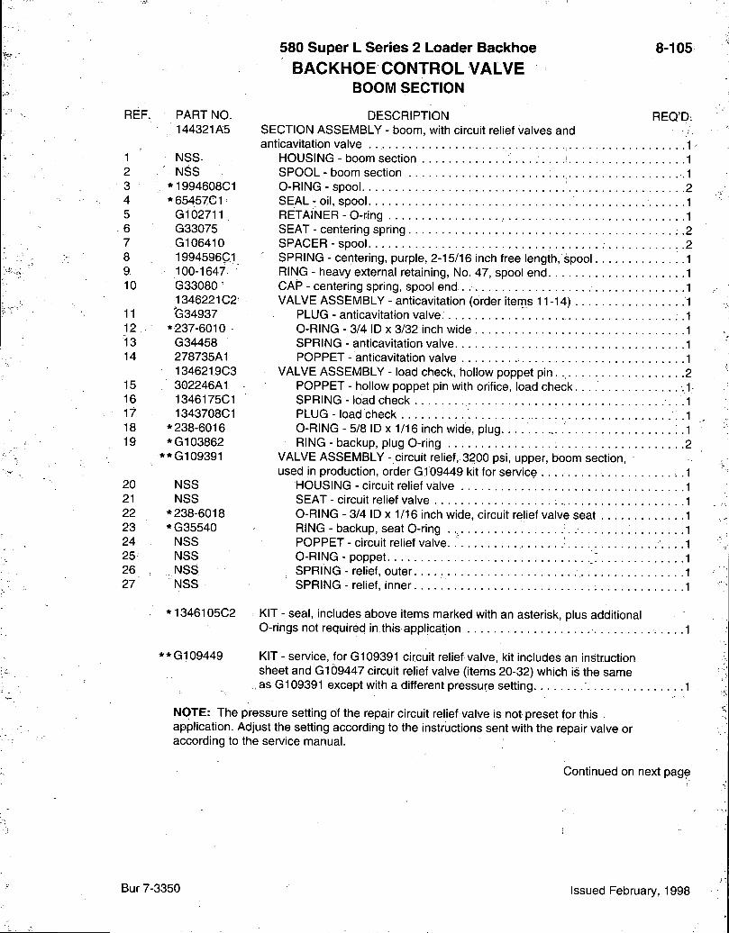
580 Super L Series 2 Loader Backhoe BACKHOE CONTROL VALVE
BOOM SECTION
8-105
REF. PART NO. 144321A5
1 NSS-2 NSS 3 *1994608C1 4 *65457C1 5 G102711 6 G33075 7 G106410 8 1994596C1 9 100-1647 10 G33080'
1346221C2 11 (334937 12 . * 237-6010 13 G34458 14 278735A1
1346219C3 15 302246A1 16 1346175C1 17 1343708C1 18 * 238-6016 19 *G103862
**G109391
DESCRIPTION SECTION ASSEMBLY - boom, with circuit relief valves and anticavitation valve
HOUSING - boom section SPOOL - boom section O-RING - spool SEAL - oil, spool RETAINER - 0-ring SEAT - centering spring SPACER-spool SPRING - centering, purple, 2-15/16 inch free length, spool RING - heavy external retaining. No. 47, spool end. CAP - centering spring, spool end . VALVE ASSEMBLY - anticavitation (order iterns 11-14)
PLUG - anticavitation valve O-RING - 3/4 ID X 3/32 inch wide SPRING - anticavitation valve POPPET - anticavitation valve
VALVE ASSEMBLY - load check, hollow poppet pin. POPPET - hollow poppet pin with orifice, load check SPRING-load check PLUG - load check O-RING - 5/8 ID X 1/16 inch wide, plug RING - backup, plug 0-ring
VALVE ASSEMBLY - circuit relief, 3200 psi, upper, boom section, used in production, order G109449 kit for service
REQ'D;
20 NSS HOUSING - circuit relief valve 21 NSS SEAT - circuit relief valve 22 * 238-6018 O-RING - 3/4 ID X 1/16 inch wide, circuit relief valve seat 23 *G35540 RING - backup, seat 0-ring 24 NSS POPPET - circuit relief valve. 25 NSS O-RING - poppet 26 , NSS SPRING - relief, outer 27 NSS SPRING - relief, inner
*1346105C2
**G109449
KIT - seal, includes above items marked with an asterisk, plus additional 0-rings not required in this application
KIT - service, for G109391 circuit relief valve, kit includes an instruction sheet and 0109447 circuit relief valve (items 20-32) which is the same as G109391 except with a different pressure setting
NOTE: The pressure setting of the repair circuit relief valve is not preset for this , application. Adjust the setting according to the instructions sent with the repair valve or according to the service manual.
Continued on next page
Bur 7-3350 Issued February, 1998
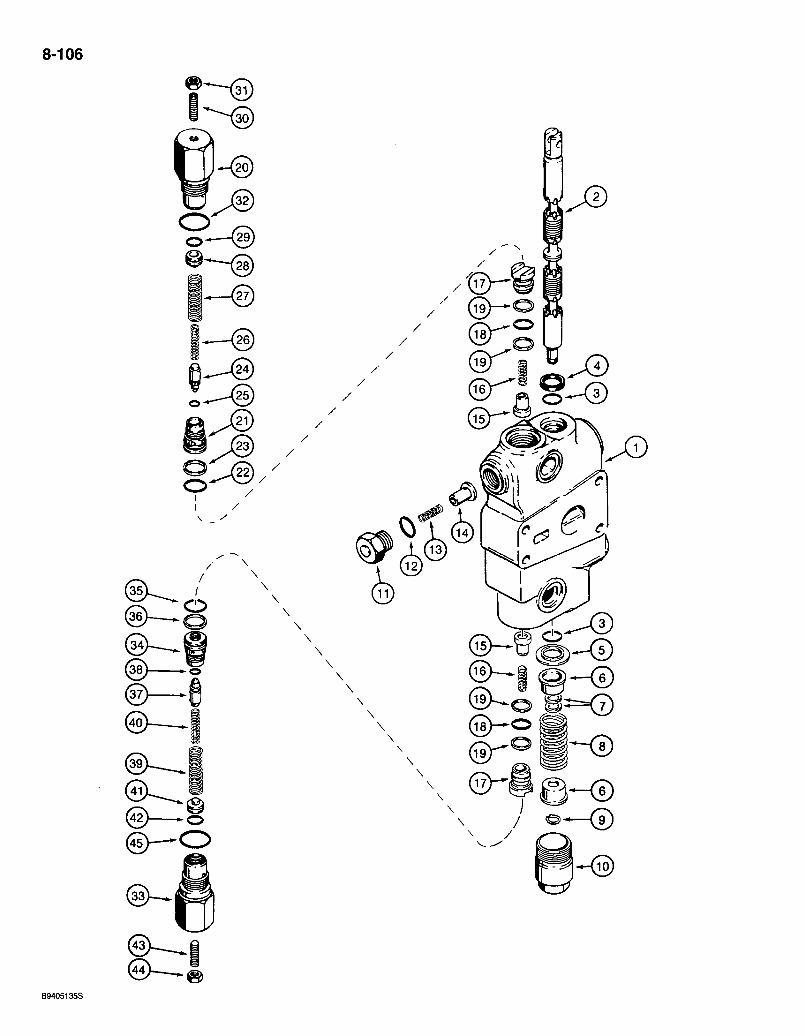
8-106
@ —
(45>—O
\
B9405135S
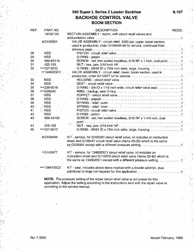
580 Super L Series 2 Loader Backhoe BACKHOE CONTROL VALVE
BOOM SECTION
8-107
REF. PART NO. 144321A5
#G109391
28 N S S 29 N S S 30 484-43116 31 425-155; 32 * * 237-6012
:*1346023C1
33 N S S 34 N S S 35 * * 238-6018 36 **G35540 37 N S S 38 N S S 39 N S S 40 • ; N S S 41 • N S S 42 N S S 43 '484-43120
44 425-1.55 45 * * 237-6012
#0109449
*G 1-10077
**1346105C2
DESCRIPTION SECTION ASSEMBLY - boom, with circuit relief valves and anticavitation valve
VALVE ASSEMBLY-- circuit relief, 3200 psi, upper, boom section, used in production, order G109449 kit for service, continued from . previous page
PISTON - circuit relief valve O-RING - piston SCREW - set, hex socket headless, 5/16 NF x 1 inch, oval point NUT - hex, jam, 5/16 inch NF O-RING - 59/64 ID x 7/64 inch wide, large, housing. . . . .
VALVE ASSEMBLY - circuit relief, lower, boom section, used in production, order G110077 kit for service
HOUSING - circuit relief valve SEAT - circuit relief valve O-RING - 3/4 ID X 1/16 inch wide, circuit relief valve seat RING - backup, seat O-ring POPPET - circuit relief valve O-RING - poppet. SPRING - relief, outer SPRING - relief, inner PISTON - circuit relief valve O-RING - piston SCREW - set, hex socket headless, 5/16 NF x 1-1/4 inch, oval point
' NUT - hex, jam, 5/16 inch NF O-RING - 59/64 ID x 7/64 inch wide, large, housing
REQ'D.
KIT - service, for G109391 circuit relief valve, kit includes an instruction sheet and G109447 circuit relief valve (items 20-3^2) which is the same as G109391 except with a different pressure setting.
KIT - service, for 1346023C1. circuit relief valve, kit includes an instruction sheet and G110078 circuit relief valve (items 33^45) which is the same as 134602301 except with a different pressure setting. . . . . . .
KIT - seal, includes above items marked with a double asterisk, plus additional 0-rings not required for this application
NOTE: The pressure setting of the repair circuit relief valve is not preset for this application. Adjust the setting according to the instructions sent with the repair valve or according to the service manual.
Bur 7-3350 Issued February, 1998
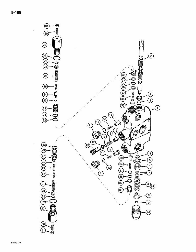
8-108
@—i
(25)—
BS97C150
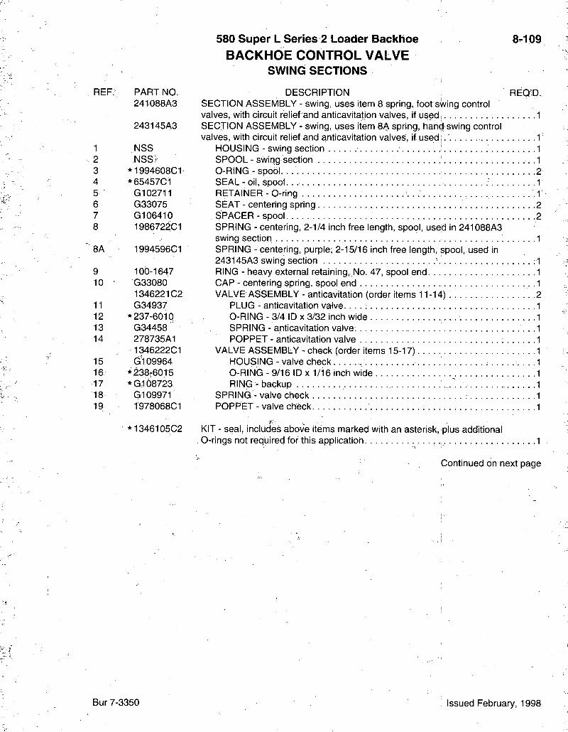
580 Super L Series 2 Loader Backhoe BACKHOE CONTROL VALVE
SWING SECTIONS
8-109
REF? PART NO. 241088A3
243145A3
1 NSS 2 NSS^: 3 *1994608C1 4 *65457C1 5 G102711 6 G33075 7 G106410 8 1986722C1
8A 1994596C1
9 100-1647 10 • G33080
1346221C2 11 G34937 12 * 237-6010 13 G34458 14 278735A1
1346222C1 15 G'I 09964 16 *238r6015 17 *G108723 18 G109971 19 1978068C1
DESCRIPTION REQ'D. SECTION. ASSEMBLY - swing, uses item 8 spring, foot swing control valves, with circuit relief and anticavitation valves, if used 1 SECTION ASSEMBLY - swing, uses item 8A spring, hand swing control valves, with circuit relief and anticavitation valves, if used .1
HOUSING - swing section 1 SPOOL - swirig section -I O-RING - spool. . 2 SEAL - oil, spool 1 RETAINER - O-ring -1 SEAT - centering spring .2 SPACER-spool 2 SPRING - centering, 2-1/4 inch free length, spool, used in 241088A3 swing section 1 SPRING - centering, purple; 2-15/16 inch free length, spool, used in 243145A3 swing section ' RING - heavy external retaining,.No. 47, spool end CAP - centering spring, spool end VALVE ASSEMBLY - anticavitation (order items 11-14)
PLUG - anticavitation va l ve . . . . ; O-RING - 3/4 ID X 3/32 inch wide SPRING - anticavitation valve. POPPET - anticavitation valve
VALVE ASSEMBLY - check (order items 15-17) HOUSING - valve check O-RING - 9/16 ID X 1/16 inch wide RING- backup • • • • • • • •
SPRING - valve check POPPET - valve check
* 1346105C2 KIT - seal, includes above items marked with an asterisk, plus additional . 0-rings not required for this application
Continued on next page
Bur 7-3350 Issued February, 1998
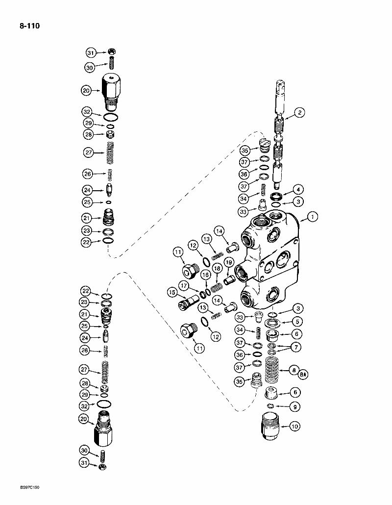
8-110
(36)—O
BS97C150
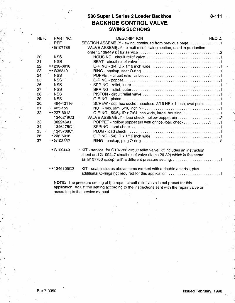
580 Super L Series 2 Loader Backhoe BACKHOE CONTROL VALVE
SWING SECTIONS
8-111
REF. PART NO. . REF
. *G107786
20 NSS 21 NSS 22 * * 238-6018 23 * *G35540 24 NSS 25 NSS 26 NSS 27 NSS 28 NSS 29 NSS 30 484-43116 31 • 425-155 32 * * 237-6012
1346219C3 33 302246A1 34 13,46175C1 35 ,134370801 36 *"238-6016 37 *G103862
REQ'D. 1
*G109449
**1346105C2
DESCRIPTION SECTION ASSEMBLY - swing, continued from previous page. . . . . . .
VALVE ASSEMBLY - circuit relief, swing section, used in production, order G109449 kit for service. . 2
HOUSING - circuit relief valve SEAT - circuit relief valve O-RING - 3/4 ID X 1/16 incli wide RING - backup, seat O-ring POPPET - circuit relief valve O-RING - poppet. . SPRING - relief, inner SPRING - relief, outer
- PISTON - circuit relief valve O-RING - piston SCREW - set, hex socket headless, 5/16 NF x 1 inch, oval point NUT-hex , jam, 5/16 inch NF O-RING - 59/64 ID x 7/64 inch wide, large, housing.
VALVE ASSEMBLY - load check, hollow poppet pin POPPET - hollow poppet pin with orifice,-load check SPRING- load check PLUG - load check O-RING-5/8 ID x 1/16 inch wide RING - backup, plug O-ring 2
KIT - service, for G107786 circuit relief valve, kit includes ah instruction sheet and G109447 circuit relief valve (items 20-32) which is the same as G107786 except with a different pressure setting 1
KIT - seal, includes above items marked with a double asterisk, plus additional 0-rings not required for this application
NOTE: The pressure setting of the repair .circuit relief valve is not preset for this application. Adjust the setting according to the instructions sent with the repair valve or according to the service manual.
Bur 7-3350 Issued February, 1998
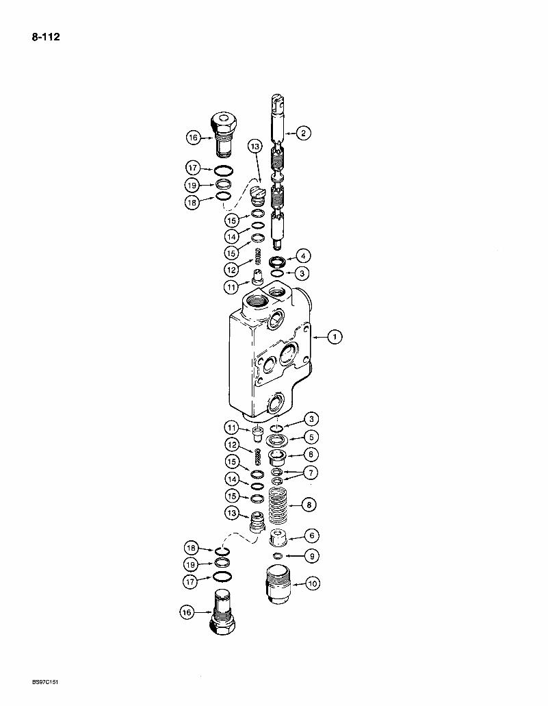
8-112
BS97C151
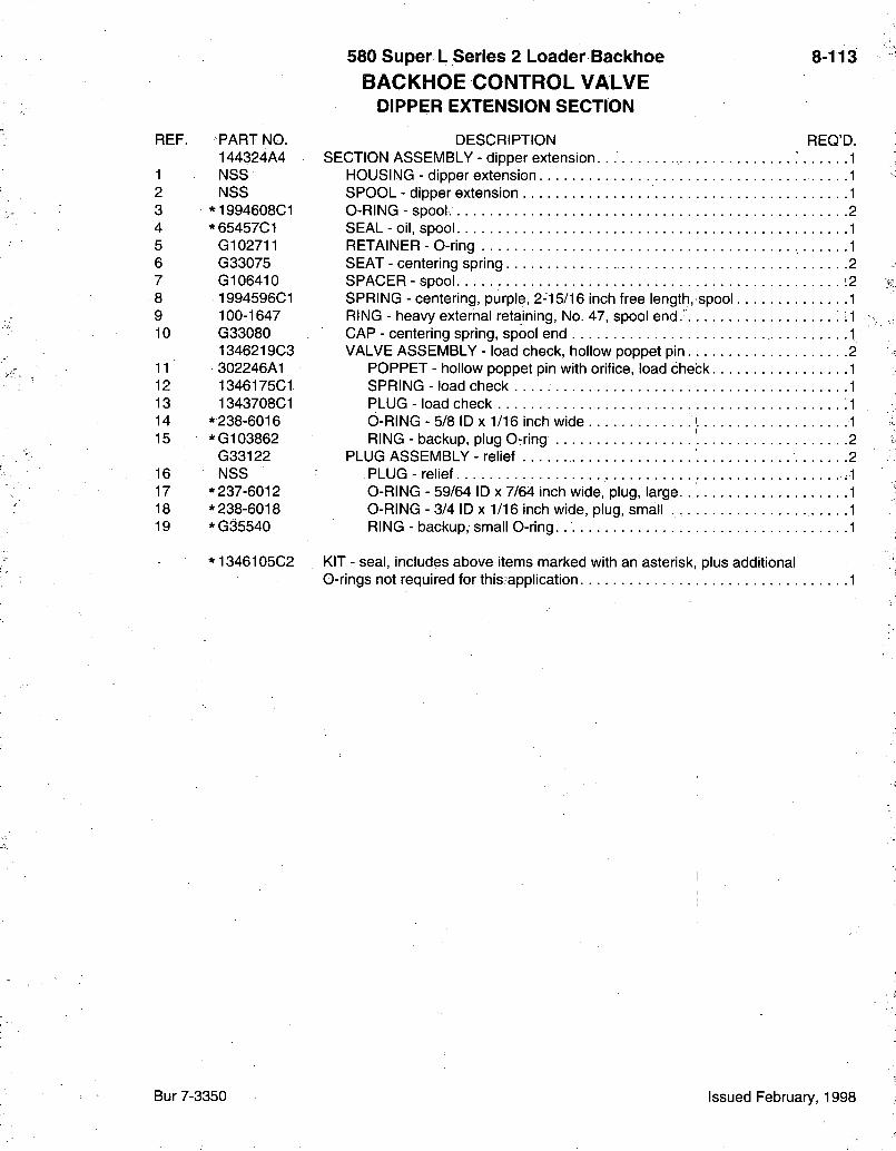
580 Super L Series 2 Loader Backhoe BACKHOE CONTROL VALVE
DIPPER EXTENSION SECTION
8-113
REF. PART NO. 144324A4
1 NSS 2 NSS 3 *1994608C1 4 *65457C1 5 G102711 6 G33075 7 G106410 8 1994596C1 9 100-1647 10 G33080
134621903 11 302246A1 12 134617501 13 134370801 14 * 238-6016 15 *G103862
G33122 16 NSS 17 * 237-6012 18 * 238-6018 19 *G35540
134610502
DESORIPTION REQ'D. SEOTION ASSEMBLY - dipper extens ion. . . 1
HOUSING - clipper extension 1 SPOOL - clipper extension 1 0-RING - spool. 2 SEAL - oil, spool 1 RETAINER - 0-ring 1 SEAT - centering spring 2 SPAOER-spool -2 SPRING - centering, purple, 2-15/16 inch free length, spool 1 RING - heavy external retaining, No. 47, spool end. ^ ^1 OAP - centering spring, spool end 1 VALVE ASSEMBLY - load check, hollow poppet pin 2
POPPET - hollow poppet pin with orifice, load check 1 SPRING- load check • • -1 PLUG- load check -1 0-RING - 5/8 ID X 1/16 inch wide 1 RING - backup, plug Orring 2
PLUG ASSEMBLY - relief • -2 PLUG-rel ief -1 0-RING - 59/64 ID x 7/64 inch wide, plug, large 1 O-RING - 3/4 ID X 1/16 inch wide, plug, small .1 RING - backup, small O-ring. 1
KIT - seal, includes above items marked with an asterisk, plus additional O-rings not required for this application. 1
Bur 7-3350 Issued February, 1998
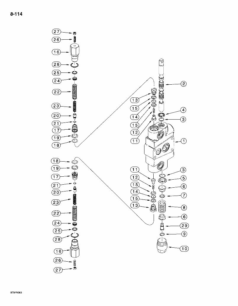
8-114
CD &
BT97N063
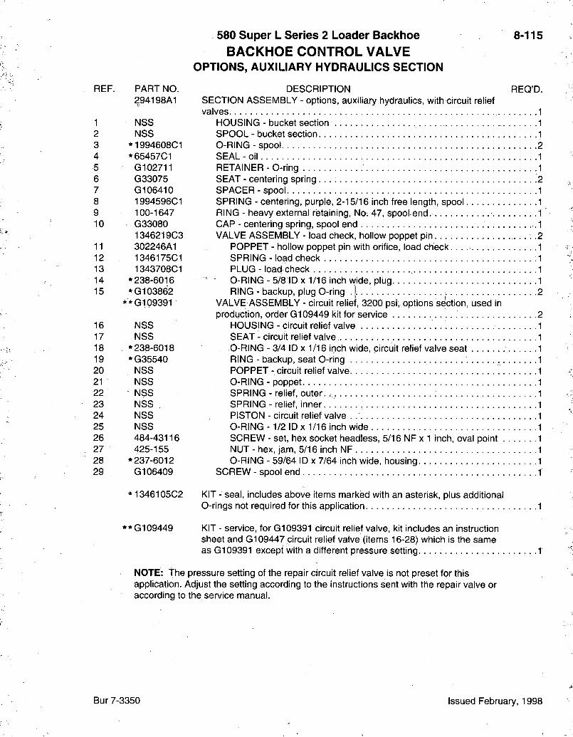
REF. PART NO. 294198A1
1 NSS 2 NSS 3 *1994608C1 4 *65457C1 5 G102711 6 G33075 7 G106410 8 1994596C1 9 100-1647 10 G33080
1346219C3 11 302246A1 12 1346175C1 13 1343708C1 14 * 238-6016 15 *G103862
**G109391
16 NSS 17 NSS 18 * 238-6018 19 *G35540 20 NSS 21 NSS 22 NSS 23 NSS . 24 NSS 25 NSS 26 484-43116 27 425-155 28 * 237-6012 29 G106409
*1346105C2
'G109449
580 Super L Series 2 Loader Backhoe BACKHOE CONTROL VALVE
OPTIONS, AUXILIARY HYDRAULICS SECTION
8-115
REQ'D. DESCRIPTION SECTION ASSEMBLY - options, auxiliary hydraulics, with circuit relief valves
HOUSING - bucket section SPOOL - bucket section O-RING - spool SEAL - oil RETAINER - 0-ring SEAT - centering spring SPACER - spool SPRING - centering,.purple, 2-15/16 inch free length, spool RING - heavy external retaining, No. 47, spool end. CAP - centering spring, spool end VALVE ASSEMBLY - load check, hollow poppet pin.
POPPET - hollow poppet pin with orifice, load check. SPRING- load check PLUG - load check ,
' - O-RING - 5/8 ID X 1/16 inch wide, plug. RING - backup, plug O-ring 2
VALVE ASSEMBLY - circuit relief, 3200 psi, options section, used in production, order G109449 kit for service 2
HOUSING - circuit relief valve SEAT - circuit relief valve O-RING - 3/4 ID X 1/16 inch wide, circuit relief valve seat RING - backup, seat O-ring POPPET - circuit relief valve O-RING - poppet. SPRING - relief, outer. . SPRING - relief, inner PISTON - circuit relief valve O-RING - 1/2 ID X 1/16 inch wide SCREW - set, hex socket headless, 5/16 NF x 1 inch, oval point NUT-hex , jam, 5/16 inch NF O-RING - 59/64 ID x 7/64 inch wide, housing
SCREW - spool end
KIT - seal, includes above items marked with an asterisk, plus additional 0-rings not required for this application
KIT - service, for G109391 circuit relief valve, kit includes an instruction sheet and G109447 circuit relief valve (items 16-28) which is the same as G109391 except with a different pressure setting.
NOTE: The pressure setting of the repair circuit relief valve is not preset for this application. Adjust the setting according to the instructions sent with the repair valve or according to the service manual.
Bur 7-3350 Issued February, 1998
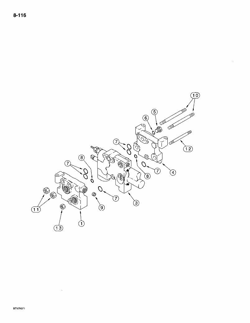
8-116
1

580 Super L Series 2 Loader Backhoe AUXILIARY VALVE
HAND HELD HYDRAULICS ONE SPOOL
8-117
REF. PART NO. 121741A1
1 121638A2 3 131197A1
4 121639A2 5 218-5158 6 237-6012 7 238-6117 8. 238-6112 9 137039A1 10 134612903 11 829-1312 12 - 134612803 13 829-1310
DESORIPTION REQ'D. VALVE ASSEMBLY - auxiliary, for hand held hydraulics 1
MANIFOLD - cover, inlet/outlet 1 SEOTION ASSEMBLY - hand held auxiliary hydraulics, parts list page 8-119 1 MANIFOLD - cover, power beyond 1 PLUG - hex, 1-1/16-12 inch O-ring boss 1;
0-RING - 59/64 ID x 7/64 inch wide 1 O-RING -13/16 ID X 3/32 inch wide, section ports, large . .6 O-RING -1 /2 ID X 3/32 inch wide, section ports, small 2 PLUG - hex socket 1 STUD- t ie • • -2 NUT - hex, 12 mm -1.75, class 10 4 STUD- t ie 1 NUT - hex, 10 mm -1 .5 , class 10.9 2
Bur 7-3350 Issued February, 1998
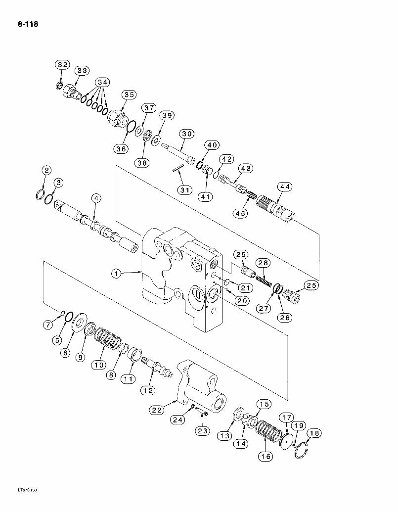
8-118
BT97C153

580 Super L Series 2 Loader Backhoe AUXILIARY VALVE HAND HELD SECTION
8-119
REF. PART NO. 131197A1
1 NSS 2 71121 3 G110391
131196A1 4 . NSS 5 G1-10391 6 G108630 7 237-6002 8 1980085C1 9 G108914 10 130932A1 11 G108913 12 1980084C3 13 G108912 14 211-1007 15 G108911 16 130919A1 17 1341975C1 18 100-21118 19 G107780 20 238-6011 21 238-6015 22 129391A1 23 61-31016;-24 495-11022
1542563C1 25 NSS 26 G108723 27 238-6015 28 1994581C1 29 1543329C1
1343791C2
30 1980302C2 31 38-1812 32 G101066 33 ' 1980227C1 34 • 1986628C1 35 - 1980226C1 36 237-6010 37 G108956 38 F13537 39 G108957
1994677C1 40 100-2156 41 1346312C2 42 238-6012 43 1957856C1
44 1957855C3 45 1957887C1
DESCRIPTION SECTION ASSEMBLY - hand held auxiliary hydraulics
HOUSING - section WIPER - shaft seal O-RlNG - spool SPOOL ASSEMBLY - detent
. SPOOL - detent O-RING-spool RETAINER - O-ring 0-RlNG -1 /4 ID x 1/16 inch wide STOP - spool SEAT - spring, upper SPRING - centering SEAT - spring, lower SHAFT - detent
WASHER - detent, ball BALL - chrome alloy steel, 7/32 inch, grade 24 WASHER - detent, ball SPRING - detent RETAINER - detent, spring RING - internal .retaining. No. 118 ; . . . PLUG - check valve O-RING - 5/16 ID X 1/16 inch wide O-RING - 9/16 ID X 1/16 inch wide HOUSING - detent BOLT - hex socket, 10 NC x 1 inch, detent housing retaining WASHER - flat, 7/32 x 7/16 x 3/64 inch VALVE ASSEMBLY - check
PLUG - load check RING - backup O-RING - 9/16 ID X 1/16 inch wide SPRING - load check PLUG - poppet
KIT - flow control adjustment, includes an instruction sheet (order items 30-39)
ROD ASSEMBLY - adjusting, flow control . . . PIN - roll, 1/8 X 3/4 inch
SEAL - oil, adjusting rod NUT - compression O-RING - 3/8 ID X 9/16 inch wide, rod seal PLUG - adjusting, flow O-RING - 3/4 ID X 3/32 inch wide RACE - bearing, thin BEARING - thrust RACE - bearing, thick
SLEEVE ASSEMBLY - control RING - internal retaining. No. 56 PLUG - sleeve O-RING - 3/8 ID X 1/16 inch wide SPOOL - flow control, select fit with item 44 sleeve, must retain together SLEEVE-f low control
-SPRING - control, flow control, not included in sleeve assembly. . .
REQ'D.
Bur 7-3350 Issued February, 1998
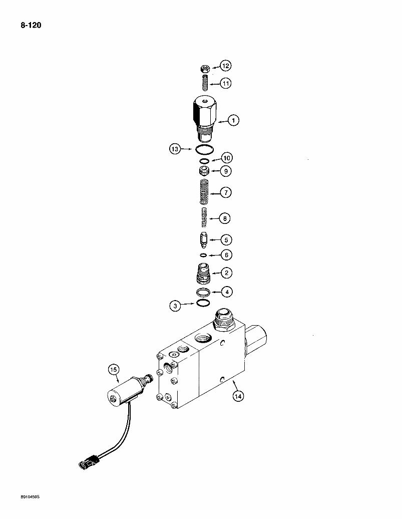
8-120
(3>-0
( 3 > - 0
B910459S
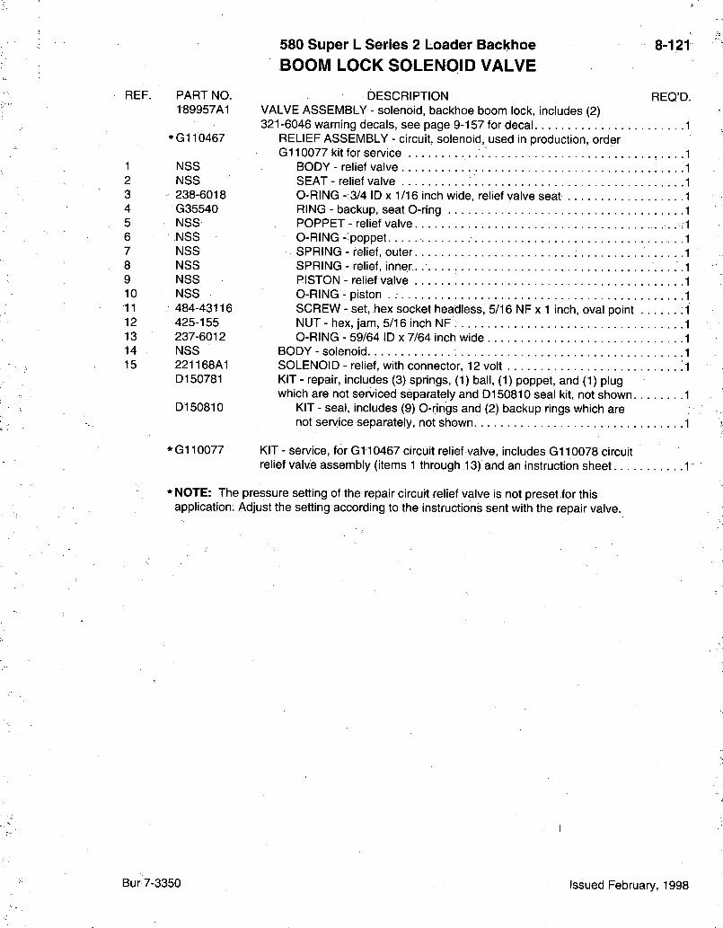
580 Super L Series 2 Loader Backhoe BOOM LOCK SOLENOID VALVE
8-121
REF.
1 2 3 4 5 6 7 8 9 10 11 12 13 14 15
PART NO. 189957A1
*G110467
NSS NSS 238-6018 G35540 NSS
- NSS NSS NSS NSS NSS 484-43116 425-155 237-6012 NSS 221168A1 D150781
D150810
*G110077
DESORIPTION REQ'D. VALVE ASSEMBLY - solenoid, backhoe boom lock, includes (2) 321-6046 warning decals, see page 9-157 for decal 1
RELIEF ASSEMBLY - circuit, solenoid, used in production, order G i l 0077 kit for service . . . . . 1
BODY - relief valve 1 SEAT - relief valve 1 O-RING - 3/4 ID x 1/16 inch wide, relief valve seat .1 RING - backup, seat O-ring 1 POPPET - relief valve • • 1 O-RING - poppet • .1 SPRING - relief, outer .1 SPRING - relief, inner. 1 PISTON - relief valve 1 O-RING - piston 1 SOREW - set, hex socket headless, 5/16 NF x 1 inch, oval point .1 NUT-hex , jam, 5/16 inch N F ; 1 O-RING - 59/64 ID x 7/64 inch wide 1
BODY - solenoid 1 SOLENOID - relief, with connector, 12 volt 1 KIT - repair, includes (3) springs, (1) ball, (1) poppet, and (1) plug which are not serviced separately and D150810 seal kit, not shown 1
KIT - seal, includes (9) O-rings and (2) backup rings which are not service separately, not shown 1
KIT - service, for G i l 0467 circuit relief valve, includes G110078 circuit relief valve assembly (items 1 through 13) and an instruction sheet 1
*NOTE: The pressure setting of the repair circuit relief valve is not preset for this application; Adjust the setting according to the instructions sent with the repair valve.
Bur7-3350 Issued February, 1998
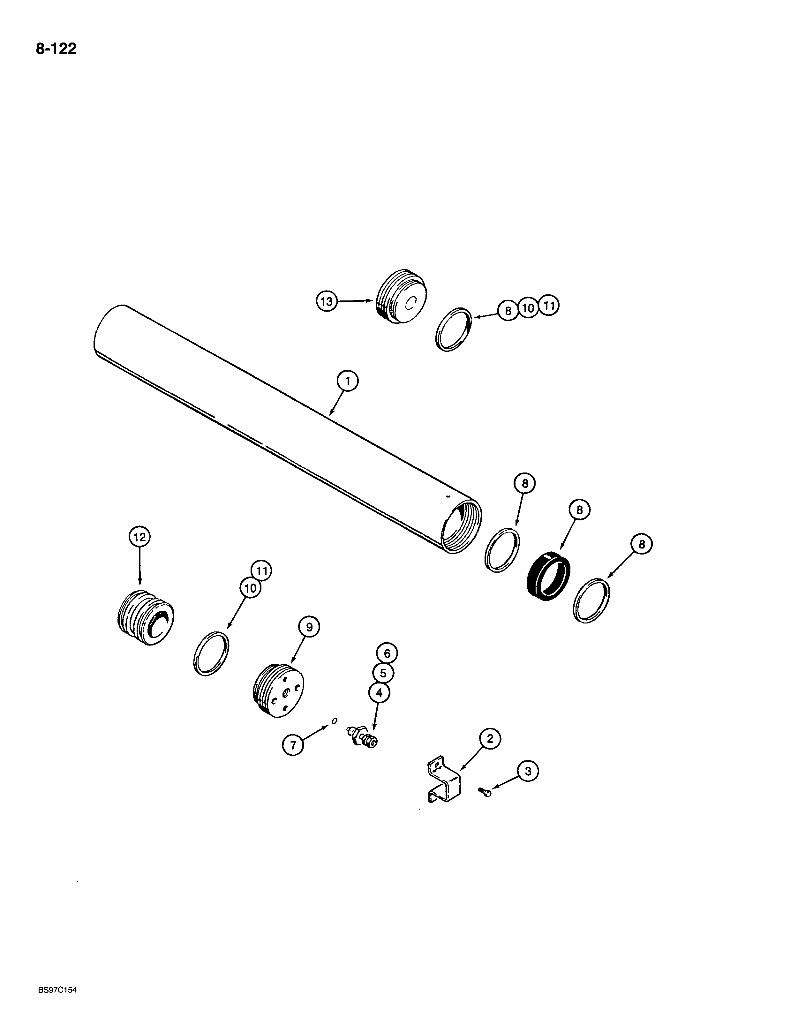
8-122
BS97C154

580 Super L Series 2 Loader Backhoe ACCUMULATOR ASSEMBLY
RIDE CONTROL
8-123
REF. PART NO. 234412A1
1 -NSS 2 . 192895A1 3 276-2456
1978142C1 4 NSS 5 1978143C1 6 1978144C1 7 1978158C1 8 1978141 CI
9 NSS 10 NSS 11 NSS 12 NSS 13 NSS 14 L129440
DESCRIPTION REQ'D. ACCUMULATOR ASSEMBLY - hydraulic, ride control 1
BODY - accumulator, tube 1 GUARD-va lve 1 SCREW - self-tapping, hex head, No. 10 NC x 3/8 inch .2 VALVE ASSEMBLY - charge, gas
VALVE - accumulator charging CORE - valve CAP-va lve
O-RING-valve KIT - seal, includes (1) V-type O-ring, (2) Teflon bearing rings and (1) body end seal ring 1 GLAND - gas valve 1 O-RING - gland 2 RING - backup, if used 2 PISTON - accumulator. .1 GLAND - end cap • • • "I
DECAL - hydraulic accumulator application instructions, mounts on accumulator, not shown, see page 9-157 for decal 1
Bur 7-3350 Issued February, 1998
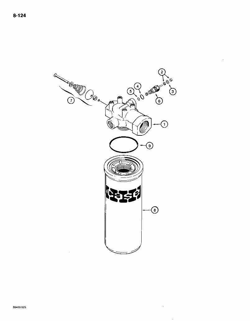
8-124
6
B9405152S
580 Super L Series 2 Loader Backhoe HYDRAULIC OIL FILTER
8-125
REF. PART NO. 122536A1
1 NSS N6755 N6941
2 129-667 3 493-21020 4 237-6006 5 238-5011 6 NSS 7 NSS
N9025 8 NSS 9 238-5230
DESCRIPTION FILTER ASSEMBLY - hydraulic oil
HEAD-filter INDICATOR ASSEMBLY - restriction, electric
KIT - restriction indicator repair (order items 2-5) NUT - hex, left-hand thread, No. 10 NF. . . . . WASHER - internal tooth lock, 3/16 inch. . . . O-RING -15/32 ID x,5/64 inch wide, outer.. . 0-RING - 5/16 ID X 1/16 inch wide, inner . . . ,
INDICATOR - restriction, electric VALVE - bypass. . . ELEMENT ASSEMBLY - filter
ELEMENT - filter O-RING - 2-1/2 ID X 1/8 inch wide, filter to head
REQ'D.
Bur 7-3350 Issued February, 1998
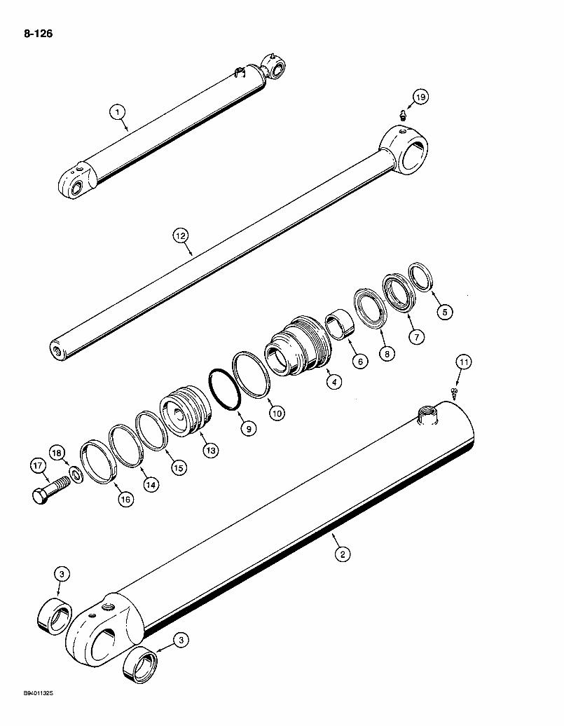
8-126
580 Super L Series 2 Loader Backhoe LOADER LIFT GYLINDERS
8-127
REF. 1
i2 3
4 5
6 .
7 8 . 9 10 11 12 13 14 15 16 17 18 19
PART NO. 112366A2
112432A1 1980335G1 N S S 1980321C2
* D95143 *G102425 *1542875C1
1542999C1 1542998C1
* 238-5233 *G32122 -276-2446 133083A1
' 135161A1 *G102287 * SI 09444 * SI 09445
25974R1 G32303 219-1
D E S C R I P T I O N R E Q ' D : C Y L I N D E R A S S E M B L Y - 8 3 (3-1/4) I D x 7 6 6 mm (30-1/8 inch) stroke, lift, right-hand and left-hand, see note 2
T U B E A S S E M B L Y - cylinder 1 B U S H I N G - t u b e •• 2
G L A N D A S S E M B L Y - cylinder G L A N D - cylinder W I P E R - piston rod B U S H I N G - center KIT - seal, NSS , order 1543260C1 kit below
S E A L - rod, N S S , order 1543260C1 kit below. . S E A L - buffer, NSS , order 1543260C1 kit below
0 - R I N G - 2-7/8 ID x 1/8 inch wide, gland R I N G - backup
S C R E W - self-tapping, hex head, No. 8 N C x 3/8 inch R O D - piston, 4 4 mm (1 -3/4 inch) diameter, cylinder, without bushings P I S T O N - cylinder S E A L - piston R I N G - backup, piston seal R I N G - wear, piston B O L T - hex, 1 N F x 2-1/2 inch, grade 8 W A S H E R - flat, special, 1 inch, hardened F ITT ING - grease, straight, 1/8 P T x 21 /32 inch
1543260C1 - K IT - seal, includes all items with an asterisk and an instruction sheet. .1
NOTE: The cylinder assembly part number is stamped on some cylinder glands or tubes.
Bur 7-3350 Issued February, 1998
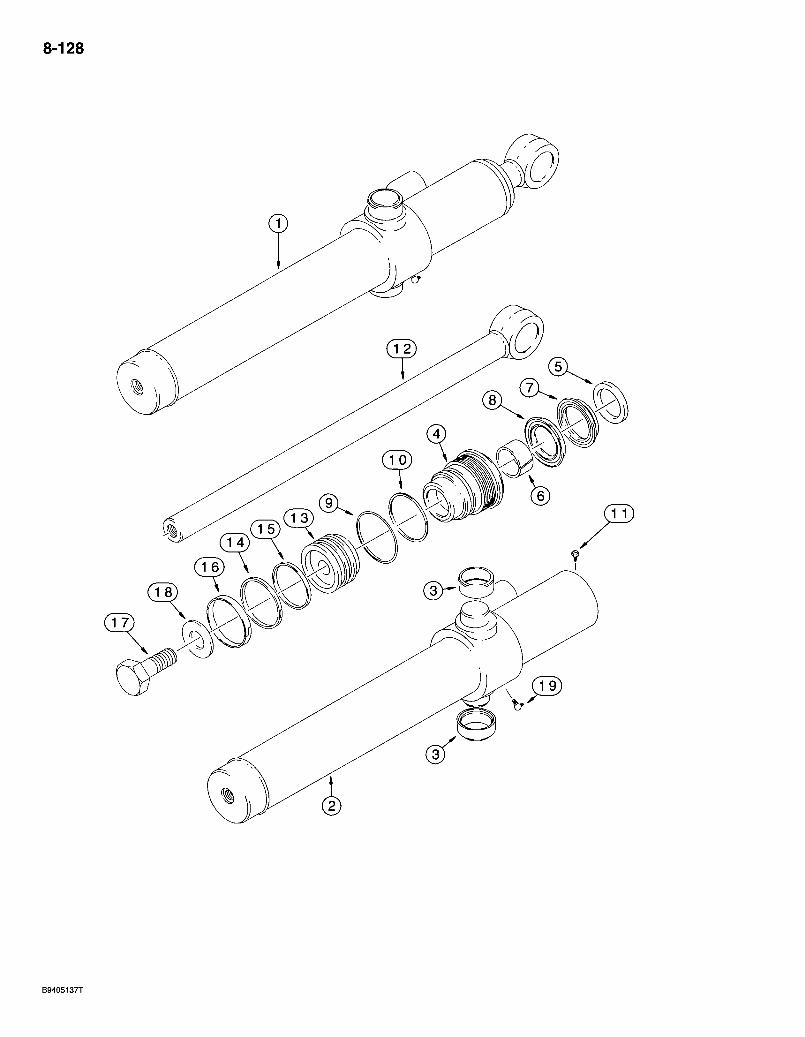
8-128

580 Super L Series 2 Loader Backhoe LOADER BUCKET CYLINDERS
8-129
REF. 1
2 3
4 5 . 6
7 8 9 10 11 12 13 14 15 16 17 18 19
PART NO. 113133A2
1131,35A2 G108512 NSS G109881
*D95142 *GJ 02424 * 1542874C1
1542997C1 1542996C1
*238-5231 *G109298
276-2446 110307A1 G108518
*G102288 *G100444 *G100449
25863R1 S94643 219-55
DESCRIPTION REQ'D. CYLINDER ASSEMBLY - 76 (3) ID x 522 mm (20-9/16 inch) stroke, bucket, left-hand and right-hand, includes bushings in cylinder tube and without bushings at rod eye, see note -2
TUBE ASSEMBLY - cylinder . . 1 BUSHING-tube • .2
GLAND ASSEMBLY - cylinder GLAND - cylinder WIPER - piston rod BUSHING - center, gland KIT - seal, NSS, order 1543256C1 kjt below
SEAL - rod, NSS, order 1543256C1 kit below. SEAL - buffer, NSS, order 1543256C1 kit below.
0-RING - 2-5/8 ID x 1/8 inch wide, gland RING - backup, gland 0-ring
SCREW - self-tapping, hex head," No. 8 NC x 3/8 inch ROD - piston, 38 mm (1-1/2 inch) diameter, without bushings in eye PISTON - cylinder
.SEAL-piston jRING - backup, piston seal . I RING - wear, piston iBOLT-hex, 3/4 NFx 2-1/2 inch, grades WASHER - flat, special, hardened FITTING - grease, 90 degree, 1/8 PT x 27/32 inch . . .
* 1543256C1 KIT - seal, includes all items with an asterisk and an instruction sheet. .1
NOTE: The cylinder assembly part number is stamped on some cylinder glands or tubes.
Bur 7^3350 Issued February, 1998

8-130
580 Super L Series 2 Loader Backhoe LOADER CLAM CYLINDERS
8-131
REF. PART NO. 1 1346189C1
1 1346190C1
2 1346191 CI 2 1346192C1 3 30634
NSS 4 G109884 5 *D95143 6 *G102425
*1542875C1 8 1542999C1 9 1542998C1 10 * 238-5231 11 *G109298 12 276-2446 13 1346195C1 14 30634 15 1340798C1 16 *G102288 17 *G100444 18 *G100449 19 25974R1 20 G32303 21 219-1 22 219-55
*1543267C1
DESCRIPTION CYLINDER ASSEMBLY - 76 (3) ID x 231 mm (9 inch) stroke, clam, right-hand, see note CYLINDER ASSEMBLY - 76 (3) ID x 231 mm (9 inch) stroke, clam, left-hand, see note
TUBE ASSEMBLY - cylinder, right-hand TUBE ASSEMBLY - cylinder, left-hand
BUSHING - 1346191C1 or 1346192C1 tube GLAND ASSEMBLY - cylinder
GLAND - cylinder WIPER - piston rod BUSHING - center KIT - seal, NSS, order1543267C1 kit below
SEAL - rod, NSS, order 1543267C1 kit below SEAL - buffer, NSS, order 1543267C1 kit below
0-RING - 2-5/8 ID x 1/8 inch wide, gland RING - backup, gland 0-ring
SCREW - self-tapping, hex head. No. 8 NC x 3/8 inch ROD ASSEMBLY - piston, 44 mm diameter
BUSHING -PISTON - cylinder SEAL - piston RING - backup, piston seal RING - wear, piston BOLT - hex, 1 NF x 2-1/2 inch, grade 8 WASHER - flat, special, 1 inch, hardened FITTING - grease, straight, 1/8 PT x 21/32 inch FITTING - grease, 90 degree, 1/8 PT x 27/32 inch
REQ'D.
KIT - seal, includes all items with an asterisk and an instruction sheet.
NOTE: The cylinder assembly part number is stamped on some cylinder glands or tubes.
Bur 7-3350 Issued February, 1998

8-132
a
c BS97C156
REF. PART NO. 1 199720A1
1 199721A1
2 199722A1 2 199723A1
NSS 4 G110519 5 *D95144 6 *G101533
*1542876C1 7 1543001 CI 8 1543000C1 9 * 238-5241 10 *G32176 11 276-2446 12 123726A1 13 123732A1 14 * G i l 0531 15 * G i l 0529 16 *G110530 17 28-2048 18 G104989 19 219-1
580 Super L Series 2 Loader Backhoe BACKHOE STABILIZER CYLINDERS
(9/16 INCH THREADED SPUD ON CYLINDER TUBE)
DESCRIPTION CYLINDER ASSEMBLY - 108 (4-1/4) ID x 553 mm (21-3/4 inch) stroke, stabilizer, right-hand, without tube or rod bushings, see note CYLINDER ASSEMBLY -108 (4-1/4) ID x 553 mm (21-3/4 inch) stroke, stabilizer, left-hand, without tube or rod bushings, see note
TUBE - cylinder, right-hand TUBE - cylinder, left-hand GLAND ASSEMBLY - cylinder
GLAND - cylinder WIPER - piston rod BUSHING - center KIT - seal, NSS, order 1543275C1 kit below
SEAL - rod, NSS, order 1543275C1 kit below SEAL - buffer, NSS, order 1543275C1 kit below
O-RING - 3-7/8 ID X 1/8 inch wide, gland RING - backup, gland 0-ring
SCREW - self-tapping, hex head. No. 8 NC x 3/8 inch ROD - piston, 51 mm (2 inch) diameter PISTON - cylinder SEAL - piston RING - backup, piston seal RING - wear, piston BOLT - hex, 1-1/4 NF x 3 inch, grade 8 WASHER - flat, hardened, special, 1-1/32 x 2-3/8 x 3/16 inch FITTING - grease, straight, 1/8 PT x 21/32 inch
8-133
REQ'D.
* 1543275C1 KIT - seal, includes all items with an asterisk and an instruction sheet 1
NOTE: The cylinder assembly part number is stamped on some cylinder glands or tubes.
Bur 7-3350 Issued February, 1998
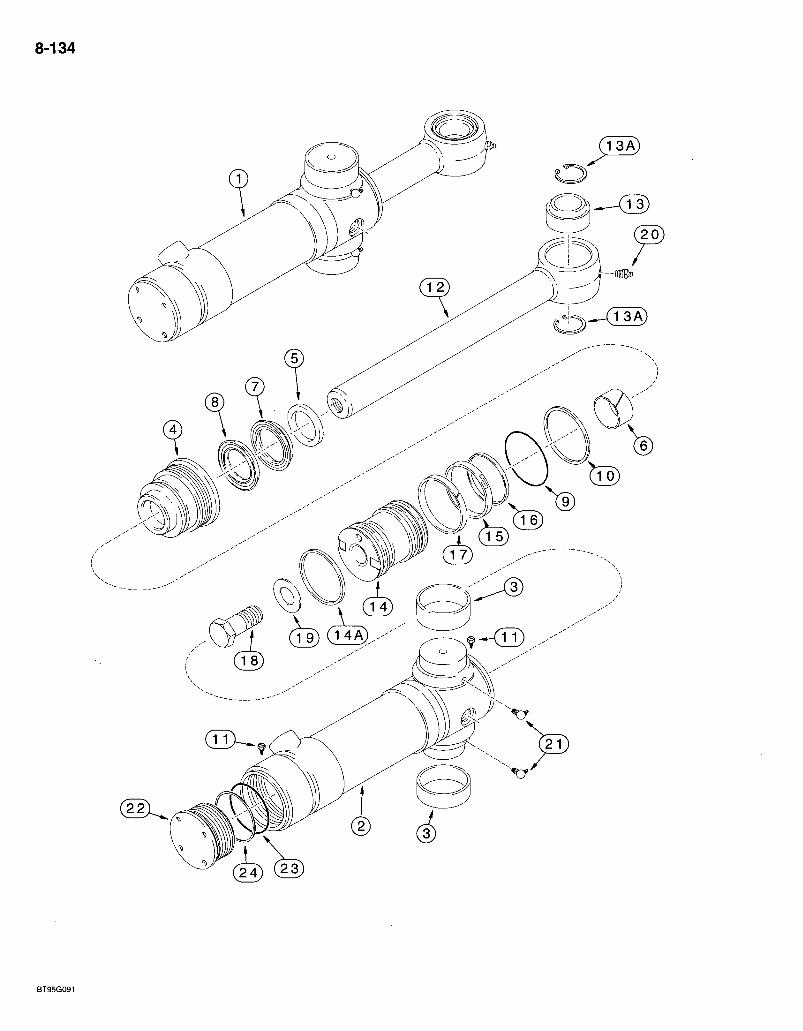
8-134
< s K ^ _ / l 3 A )
BT95G091
580 Super L Series 2 Loader Bacl<hoe BACKHOE SWING CYLINDERS
8-135
REF. PART NO. 1 139808A2
2 199953A2
2 139810A2
3 124568A2 NSS
4 0109899 5 *D95144 6 *G101533
*1542876C1 7 154300101 8 1543000C1 9 * 238-5239 10 *G109299 11 276-2446 12 177518A1 13 137248A1 13A 100-21315 14 112370A3 14A *121478A1 15 *G102285 16 *G100440 17 *G100448 18 28-1664 19 G32303 20 219-1 21 219-55
124462A1 22 124463A1 23 238-5242 24 G32176
*122535A1
DESCRIPTION REQ'D. CYLINDER ASSEMBLY -102 (4) ID X 292 mm (11-1/2 inch) stroke, swing, see note 2
TUBE ASSEMBLY - cylinder, includes 139810A2 tube, 124462A1 end cap assembly (Ref 22-24) and (1) 276-2446 screw (Ref 11), not available as an assembly, order components
TUBE ASSEMBLY - cylinder, does not include 124462A1 end cap assembly or (1) 276-2446'screw
BUSHING - tube, external GLAND ASSEMBLY - cylinder.
GLAND - cylinder WIPER-piston rod. . . . BUSHING - center KIT - seal, NSS, order 122535A1 kit below
SEAL - rod, NSS, order 122535A1 kit below. SEAL - buffer, NSS, order 122535A1 kit below. . .
0-RING - 3-5/8 X 1/8 inch wide, gland RING - backup, gland 0-ring
SCREW - self-tapping, hex head. No. 8 NC x 3/8 inch ROD ASSEMBLY - piston, 51 mm (2 inch) diameter
BUSHING - piston rod, self-aligning RING - internal retaining. No. 315
PISTON - cylinder RING - cast iron, 4 inch OD
• piston backup, piston seal wear, piston
• hex, 1-14 X 4 inch, grade 8 WASHER - flat. special, 1 inch, hardened FITTING - grease, straight, 1/8 PT x 21/32 inch FITTING - grease, 90 degree, 1/8 PT x 27/32 inch CAP ASSEMBLY - end, order items 22-24
CAP - end 0-RING-4 ID x 1/8 inch wide RING - backup
SEAL-RING -RINGBOLT
KIT - seal, includes all items with an asterisk and an instruction sheet. .1
NOTE: The cylinder assembly part number is stamped on some cylinder glands or tubes.
Bur 7-3350 Issued February, 1998
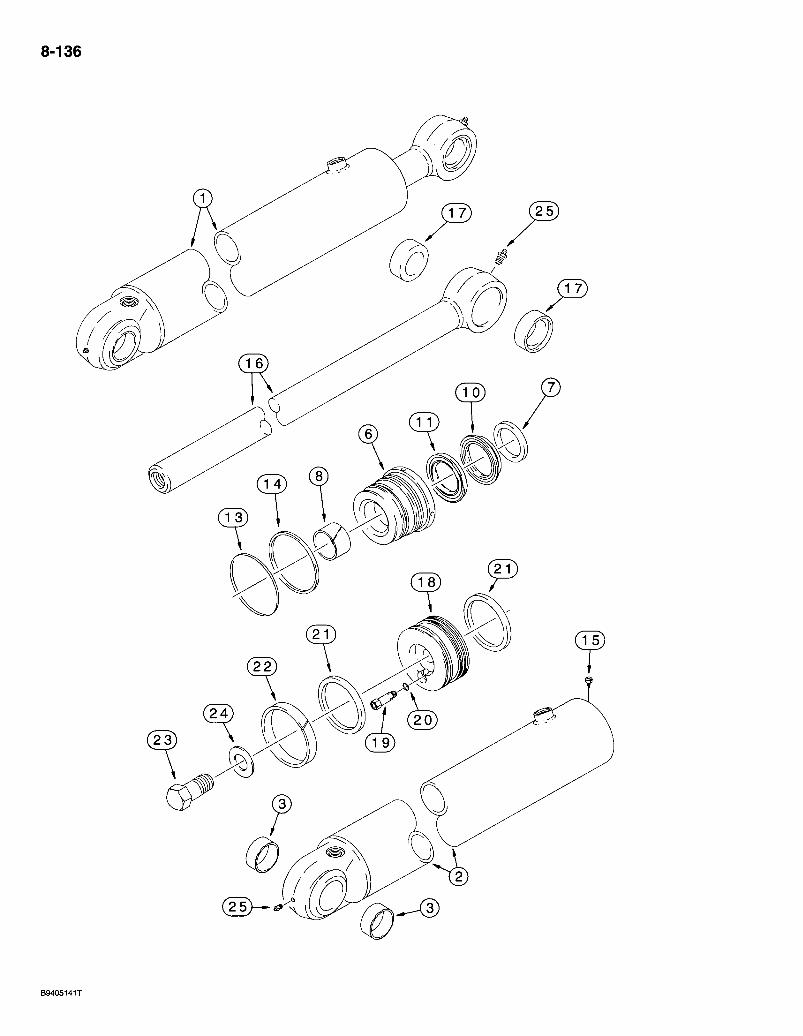
8-136
(25)-^ &
B9405141T
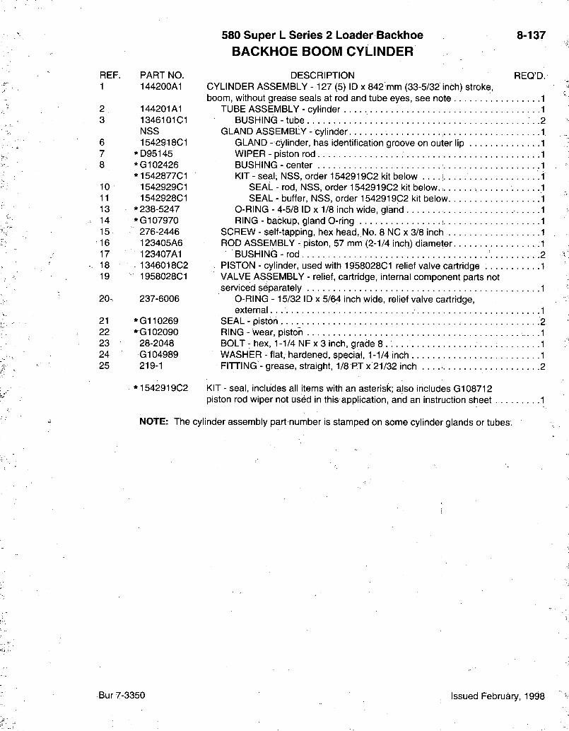
580 Super L Series 2 Loader Backlioe BACKHOE BOOM CYLINDER
8-137
REF. PART NO. 1 144200A1
2 144201A1 3 1346101 CI
NSS 6 1542918C1 7 *D95145 8 *G102426
*1542877C1 10 1542929C1 11 1542928C1 13 * 238-5247 14 *G107970 15 276-2446 16 123405A6 17 123407A1 18 1346018C2 19 1958028C1
20- 237-6006
21 * G i l 0269 22 *G102090 23 28-2048 24 G104989 25 219-1
*1542919C2
DESCRIPTION REQ'D. CYLINDER ASSEMBLY -127 (5) ID x 842 mm (33-5/32 inch) stroke, boom, without grease seals at rod and tube eyes, see note
TUBE ASSEMBLY - cylinder BUSHIN(3 - tube .
GLAND ASSEMBLY - cylinder GLAND - cylinder, has identification groove on outer lip WIPER - piston rod BUSHING - center KIT - seal, NSS, order 1542919C2 kit below
SEAL - rod, NSS, order 1542919C2 kit below SEAL - buffer, NSS, order 1542919C2 kit below
0-RING - 4-5/8 ID x 1/8 inch wide, gland RING - backup, gland 0-ring
SCREW - self-tapping, hex head,,No. 8 NC x 3/8 inch ROD ASSEMBLY - piston, 57 mm (2-1/4 inch) diameter
BUSHING- rod . PISTON - cylinder, used with 1958028C1 relief valve cartridge
VALVE ASSEMBLY - relief, cartridge, internal component parts not sen/iced separately
O-RING -15/32 ID x 5/64 inch wide, relief valve cartridge, external
SEAL - piston RING - wear, piston BOLT - hex, 1 -1/4 NF x 3 inch, grade 8 . . . . WASHER - flat, hardened, special, 1 -1/4 inch FITTING - grease, straight, 1/8 PTx 21/32 inch 2
KIT - seal, includes all items with an asterisk; also includes G108712 piston rod wiper not used in this application, and an instruction sheet 1
NOTE: The cylinder assembly part number is stamped on some cylinder glands or tubes.
Bur 7-3350 Issued February, 1998
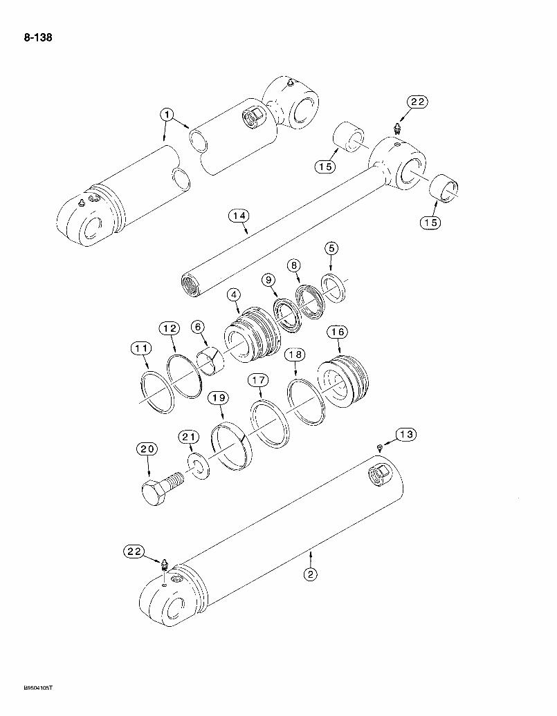
8-138
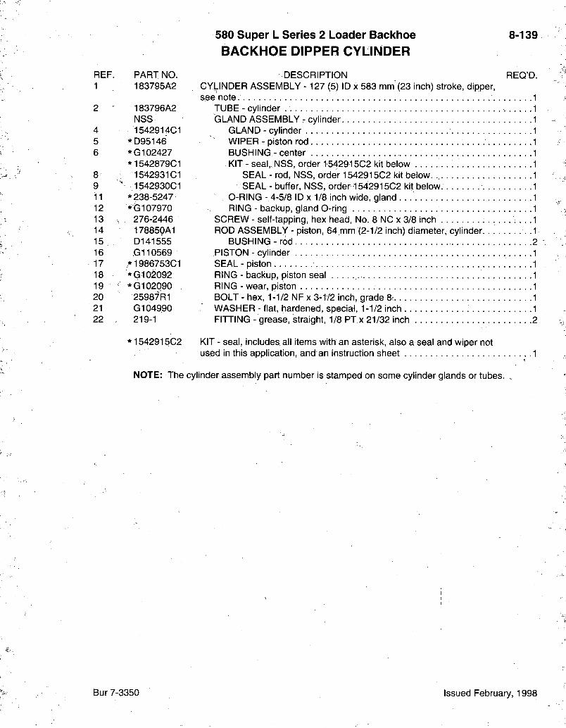
580 Super L Series 2 Loader Backhoe BACKHOE DIPPER CYLINDER
8-139
REF. PART NO. 1 183795A2
2 ' 183796A2 NSS
4 1542914C1 5 *D95146 6 *G102427
*1542879C1 8 1542931 CI 9 ' 1542930C1 11 * 238-5247 12 *G107970 13 - 276-2446 14 17885PA1 15 D141555 16 G110569 17 *1986753C1 18 *G102092 19 ' *G102090 20 25987R1 21 G104990 22 219-1
*1542915C2
DESCRIPTION REQ'D. CYLINDER ASSEMBLY -127 (5) ID x 583 mm (23 inch) stroke, dipper, see note.
TUBE - cylinder GLAND ASSEMBLY - cylinder
GLAND - cylinder WIPER - piston rod BUSHING - center KIT - seal, NSS, order 1542915C2 kit below
SEAL - rod, NSS, order 1542915C2 kit below. ., SEAL - buffer, NSS, order-1542915C2 kit below
O-RING -4-5/8 ID X 1/8 inch wide, gland RING - backup, gland 0-ring
SCREW - self-tapping, hex head, No. 8 NC x 3/8 inch ROD ASSEMBLY - piston, 64 mm (2-1/2 inch) diameter, cylinder
BUSHING - rod PISTON - cylinder SEAL - piston RING - backup, piston seal RING - wear, piston BOLT - hex, 1-1/2 NFx 3-1/2 inch, grade 8, WASHER - flat, hardened, special, 1-1/2 inch FITTING - grease, straight, 1/8 PTx 21/32 inch 2
KIT - seal, includes all items with an asterisk, also a seal and wiper not used in this application, and an instruction sheet 1
NOTE: The cylinder assembly part number is stamped on some cylinder glands or tubes.
Bur 7-3350 Issued February, 1998

8-140
c. BS97C157

580 Super L Series 2 Loader Backhoe BAGKHOE BUCKET CYLINDER
8-141
REF. PART N O . 1 235916A1
2 235917A2 N S S
4 235921A1 5 *D95146. 6 *G109908
*1542879C1 8 1542931 CI 9 154293bC1 11 * 238-5235 12 * D38858 13 276-2446 14 •l96164A1 15 D140029 16 .1986906C1 17 *G102286 18 *G100710 19 *G100711 20 28-2052 21 G104989 22 219-1
D E S C R I P T I O N R E Q ' D : C Y L I N D E R A S S E M B L Y - 8 0 ( 3 - 1 / 2 ) I D x 8 7 2 mm ( 3 4 - 5 / 1 6 inch) stroke,
bucket, see note T U B E A S S E M B L Y - cylinder
G L A N D A S S E M B L Y - cylinder G L A N D - cylinder W I P E R - piston rod B U S H I N G - center K I T - seal, N S S , order 1 5 4 2 9 2 3 C 2 kit below
S E A L - rod, N S S , order 1 5 4 2 9 2 3 C 2 kit below S E A L - buffer, N S S , order 1 5 4 2 9 2 3 C 2 kit below
0 - R I N G - 3 - 1 / 8 I D X 1/8 inch wide, gland R I N G - backup
S C R E W - self-tapping, hex head. No. 8 N C x 3 /8 inch R O D A S S E M B L Y - piston, 6 4 mm ( 2 - 1 / 2 inch) diameter, cylinder.
B U S H I N G - 5 0 x 6 0 x 2 5 . 5 mm long, piston rod P I S T O N - cylinder S E A L - piston RING - backup, piston seal R I N G - wear, piston B O L T - hex, 1-1/4 N F x 3 - 1 / 4 inch, grade 8 W A S H E R - flat, hardened, special, 1-1 /4 inch F I T T I N G - grease, straight, 1/8 P T x 2 1 / 3 2 inch . 2
* 1542923C2 K I T - seal, includes all items with an asterisk and an instruction sheet. .1
NOTE: The cylinder assembly part number is stamped on some cylinder glands or tubes.
Bur 7-3350 Issued February, 1998
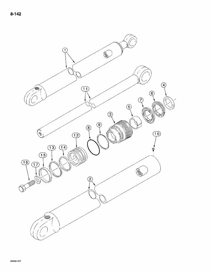
8-142
(ID Qi
B9405143T
580 Super L Series 2 Loader Backhoe BACKHOE DIPPER EXTENSION CYLINDER
8-143
REF. PART N O . 1 1340969C2
2 1340970C1 N S S
3 G109884 4 *D95143 5 *G102425
*1542875C1 6 1542999C1 7 1542998C1 8 ^ * 238-5231 9 ,*G109298 10 276-2446 11 1980296G1 12 G107277 13 *G102288 14 *G100444 15 *G100449 16 25863R1 17 S94643
* 154326701
DESORIPTION OYLINDER ASSEMBLY - 76 (3) ID x 1068 mm (42 inch) stroke, dipper extension, see note
TUBE - cylinder, without bushing GLAND ASSEMBLY - cylinder
GLAND - cylinder WIPER - piston rod BUSHING - center KIT - seal, NSS, order 154326701 kit below
SEAL - rod, NSS, order 154326701 kit below. . . SEAL - buffer, NSS, order 154326701 kit below
O-RING - 2-5/8 ID x 1/8 inch wide, gland . RING - backup, gland O-ring
SOREW - self-tapping, hex head. No. 8 NO x 3/8" inch . . : ROD - piston, 44 mm (1-3/4 inch) diameter, without bushing PISTON - cylinder SEAL - piston RING - backup, piston seal RING - wear, piston BOLT - hex, 3/4 NF x 2-1/2 inch, grade 8 WASHER - flat, special, hardened
REQ'D.
KIT - seal, includes all items with an asterisk and an instruction sheet.
NOTE: The cylinder assembly part number is stamped on some cylinder glands or tubes.
Bur 7-3350 Issued February, 1998

580 Super L Series 2 Loader Backhoe 9-1
ALPHABETICAL INDEX CHASSIS
DESCRIPTION P A G E
Backhoe Boom. 9-49,9-51 Boom Latch....... 9-53 Buckets...... ^ 9-63-9-71 Control Tower and Covers 9-25,9-27 Controls ^ 9-29-9-41 Controls - Backhoe Auxiliary Hydraulics -...9-43 Controls - Excavator Control Pattern 9-39 Dipper and Bucket 9-55,9-57 Extendable Dipper., , 9-59,9-61 Stabilizers, Plates, and Pads ....9-45 Swing Cylinders and Swing Tower 9-47
Battery Box and Right-Hand Step 9-79,9-81 Cab
Air Conditioner, Heater, and Blower 9-137 - 9-145 Air Filter 9-135 Control Panel and Wiring .9-125 Doors and Mounting and Rear Window 9-117 - 9-123 Frame, Covers and Insulation 9-115 Glass : 9-113 Headliner, Louvers, and Dome Lamp 9-133 Windshield Washers and Wipers 9-127 - 9-131
Canopy-ROPS 9-147 Chassis • .....9-77 Countenweight - Front '. 9-75 Couplers - Quick, Loader Hydraulic Tool 9-23 Decals..... 9-153 - 9-157 Fenders and Closure Panels 9-97,9-99 Floor Plates and Mats 9-95 Frost Point Assembly 9-73 Gua rd -Mud . . . 9-101 Guard - Pump and Baffle Plates 9-85 - 9-89 Hood, Engine Side Panels, and Grille Unit 9-91,9-93 Loader
Antirollback Control/Return-To-Dig Control 9-11 Buckets 9-15-9-19 Bucket and Lift Controls 9-3 Clam Controls 9-5,9-7 Frame and Mounting Parts 9-11 Guard - Valve : ^9-21 Links - Bucket and Cylinder 9-13 Self-Leveling Control 9-9
Mirror - Rear View i 9-149 Radiator Wrapper 9-83 Seats and Seat Mounting Parts 9-103 - 9-111 Slow Moving Vehicle Emblem i... 9-151 Tank - Hydraulic Oil 9-79
Bur 7-3350 Issued February, 1998
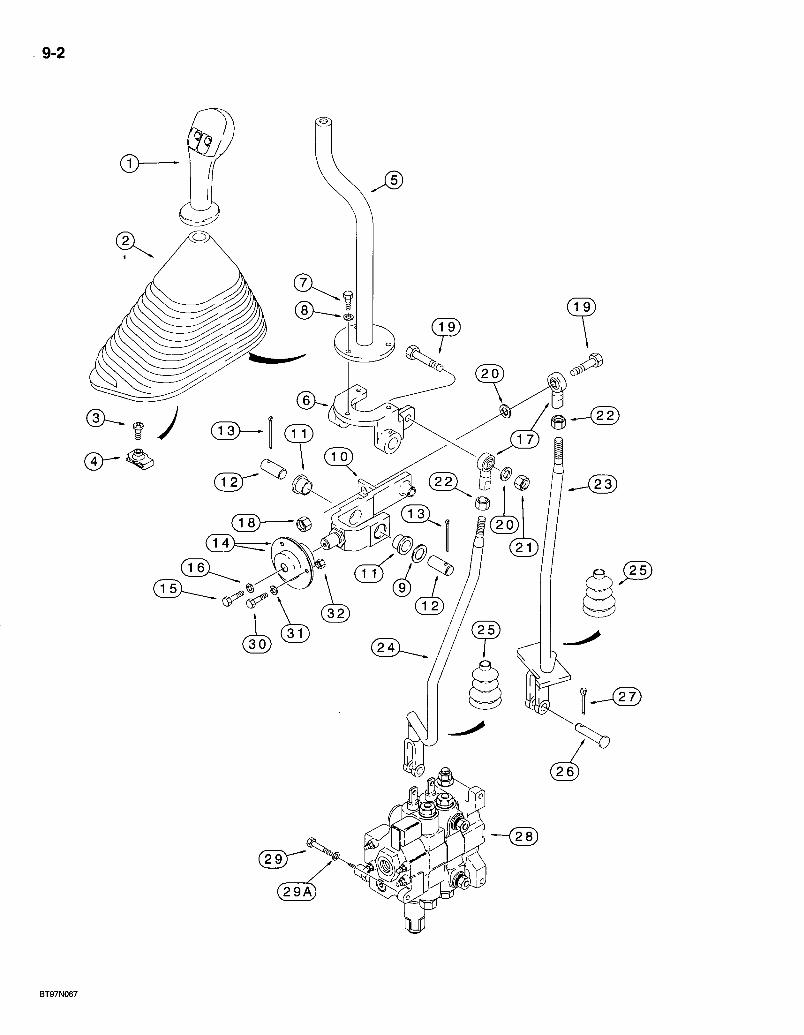
9-2
( 1 8 > — ®
BT97N067
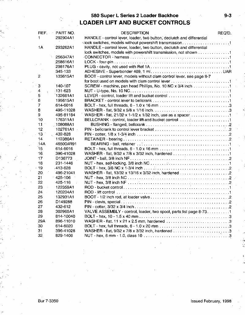
580 Super L Series 2 Loader Backhoe LOADER LIFT AND BUCKET CONTROLS
9-3
REF. PART NO. 1 292904A1
1A 293262A1
256347A1 258616A1 298176A1 345-133
2 133615A1
3 140-107 4 131-623 5 132661A1 6 195615A1 7 614-6016 8 495-11028 9 495-81184 10 176311A1 11 108088A1 12 102761A1 13 432-828 14 112380A1 14A 465004R91 15 614-6016 16 396-41028 17 D136773 18 231-1446 19 ,413-628 20; 496-21041 21 425-106 22 425-116 23 122359A1 24 120204A1 25 132931A1 26 D149288 27 432-612 28 302965A1 29 814-10040 29A 896-11010 30 614-6020 31 396-41028 32 829-1406
DESCRIPTION REO'D. HANDLE - control lever, loader, two button, declutch and differential
. lock switches, models without powershift transmission. 1 HANDLE - control lever, loader, two button, declutch and differential lock switches, models with powershift transmission, not shown 1 CONNECTOR - harness 1 LOCK - four-pin 1 PLUG - cavity, not used with Ref 1A 1 ADHESIVE - Superbonder 409,1 ml. UAR BOOT - control lever, models without clam control lever, see page 9-7 for boot used on models with clam control lever 1 SCREW - machine, pan head Phillips, No. 10 NC x 3/4 inch 1 NUT - U-type, No. 10 NC 1 LEVER - control, loader lift and bucket control 1 BRACKET - control lever to bellcrank 1 BOLT - hex, full threads, 6 -1 .0 x 16 mm 3 WASHER - flat, 9/32 x 5/8 x 1/16 inch 3 WASHER - flat, 21/32 x 1-1/2 x 1/32 inch, use as a spacer 1 BELLCRANK - control, loader lift-and bucket control 1
BUSHING - flanged, bellcrank 2 PIN - bellcrank to control lever bracket .2 PIN - cotter, 1/8 x 1-3/4 inch 2 RETAINER - bearing 2
BEARING - ball, retainer . . ; 1 BOLT - hex, full threads, 6 -1 .0 x 16 mm 1 WASHER - flat, 9/32 x 7/8 x 3/32 inch, hardened 1 JOINT-ba l l , 3/8 inch NF 2 NUT - hex, self-locking, 3/8 inch NC 1 BOLT - hex, 3/8 NC x 1-3/4 inch 2 WASHER - flat, 13/32 x 13/16 x 3/32 inch, hardened 2 NUT - hex, 3/8 inch NC 2 NUT - hex, 3/8 inch NF 2 ROD - bucket control 1 ROD- l i f t control 1 BOOT -1 /2 inch rod, at loader valve 2 PIN - clevis, special 2 PIN - cotter, 3/32 x 3/4 inch 2 VALVE ASSEMBLY - control, loader, two spool, parts list page 8-73 1 BOLT - hex, 10 -1 .5 x 40 mm . . . . . . . . 3 WASHER - flat, 11 x 21 x 2.5.mm, hardened 3 BOLT - hex, full threads, 6 - 1 .O x 20 mm 3 WASHER - flat, 9/32 x 7/8 x 3/32 inch, hardened 3 NUT - hex, 6 mm -1 .0 , class 10 .3
Bur 7-3350 Issued February, 1998
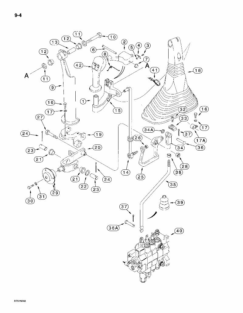
9-4
3 4 ^ ^ ^ f 3 6
BT97N068
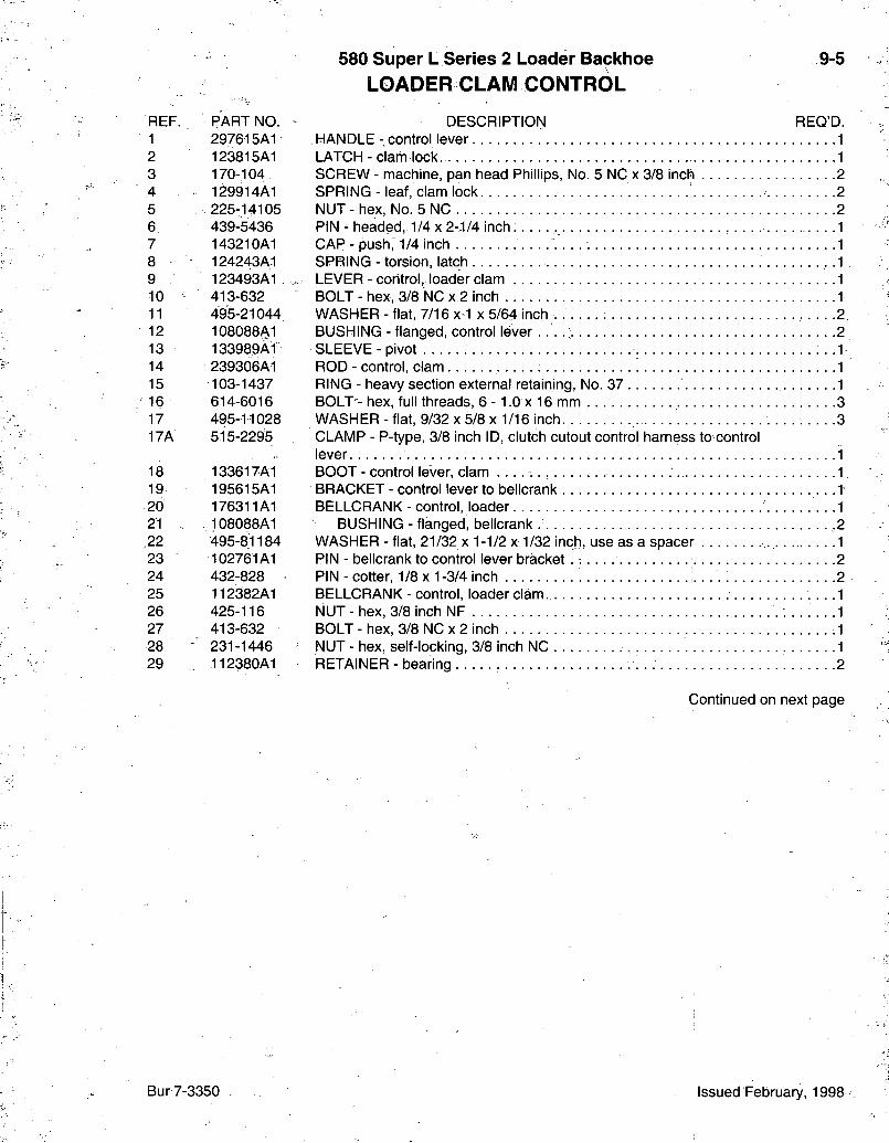
580 Super L Series 2 Loader Backhoe
LOADER CLAM CONTROL 9-5
REF. PART NO. 1 297615A1 2 123815A1 3 170-104, 4 129914A1 5 225-14105 6 439-5436 7 143210A1 8 124243A.1 9 123493A1 10 - 413-632 11 495-21044 12 108088A1 13 133989A1 14 239306A1 15 103-1437 16 614-6016 17 495-11028 17A 515-2295
18 133617A1 19 195615A1 20 176311A1 21 ,. 108088A1 .22 495-81184 23 102761A1 24 432-828 25 112382A1 26 425-116 27 413-632 28 231-1446 29 112380A1
DESCRIPTION REQ'D. HANDLE-control lever 1 LATCH - clam lock 1 SCREW - machine, pan head Phillips, No. 5 NC x 3/8 inch 2 SPRING-leaf , clam lock : 2 NUT - hex, No. 5 NC 2 PIN - headed, 1/4 x 2--1/4 inch. 1 CAP - push,' 1/4 inch 1 SPRING - torsion, latch • • • • 1 LEVER - control, loader clam 1 BOLT - hex, 3/8 NC x 2 inch 1 WASHER - flat, 7/16 x-1 x 5/64 inch . . . . . . : 2 BUSHING - flanged, control lever 2 SLEEVE-pivot ^ - I ROD - control, clam 1 RING - heavy section external retaining. No. 37 1 BOLT - hex, full threads, 6 -1 .0 x 16 mm 3 WASHER - flat, 9/32 x 5/8 x 1/16 inch. .3 CLAMP - P-type, 3/8 inch ID, clutch cutout control harness to control lever 1 BOOT - control lever, clam 1 BRACKET - control lever to bellcrank .1 BELLCRANK - control, loader 1
BUSHING - flanged, bellcrank -2 WASHER - flat, 21/32 x 1-1/2 x 1/32 inch, use as a spacer 1 PIN - bellcrank to control lever b racke t . . 2 PIN - cotter, 1/8 x 1-3/4 inch 2 BELLCRANK - control, loader clam. • • -1 NUT - hex, 3/8 inch NF 1 BOLT - hex, 3/8 NC x 2 inch 1 NUT - hex, self-locking, 3/8 inch NC 1 RETAINER- bearing 2
Continued on next page
Bur 7-3350 Issued February, 1998
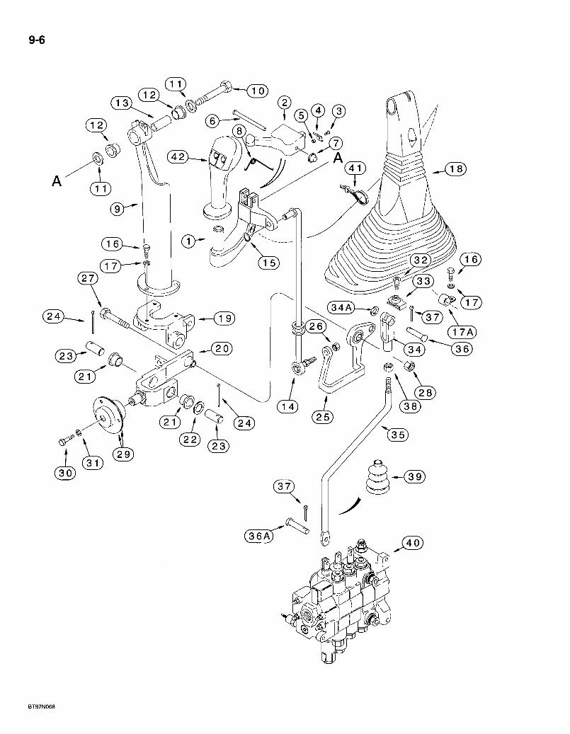
9-6
T 2 ) X
( 3 4 A ^
% OTA) 34) 1 3 6
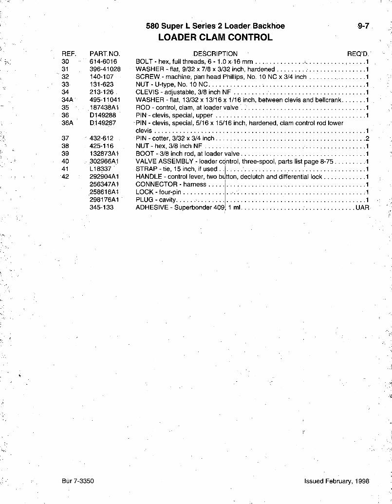
580 Super L Series 2 Loader Backhoe LOADER CLAM CONTROL
9-7
REF. PART NO. 30 614-6016 31 396-41028 32 140-107 33 131-623 34 213-126 34A 495-11041 35 ' 187438A1 36 D149288 36A D149287
37 432-612 38 425-116 39 132873A1 40 302966A1 41 LI 8337 42 292904A1
256347A1 258616A1 298176A1 345-133
DESCRIPTION REQ'D. BOLT - hex, full threads, 6 -1 .0 x 16 mm WASHER - flat, 9/32 x 7/8 x 3/32 inch, hardened SCREW - machine, pan head Phillips, No. 10 NC x 3/4 inch . . NUT-U- type, No. 10 NC CLEVIS - adjustable, 3/8 inch NF WASHER - flat, 13/32 x 13/16 x 1/16 inch, between clevis and bellcrank. ROD - control, clam, at loader valve PIN - clevis, special, upper PIN - clevis, special, 5/16 x 15/16 inch, hardened, clam control rod lower clevis PIN - cotter, 3/32 x 3/4 inch NUT - hex, 3/8 inch NF BOOT - 3/8 inch rod, at loader valve V A L V E ASSEMBLY - loader control, three-spool, parts list page 8-75 . . . STRAP - tie, 15 inch, if used HANDLE - control lever, two button, declutch and differential lock CONNECTOR - harness . . . LOCK - four-pin PLUG - cavity ADHESIVE - Superbonder 409i 1 ml UAR
Bur 7-3350 Issued February, 1998
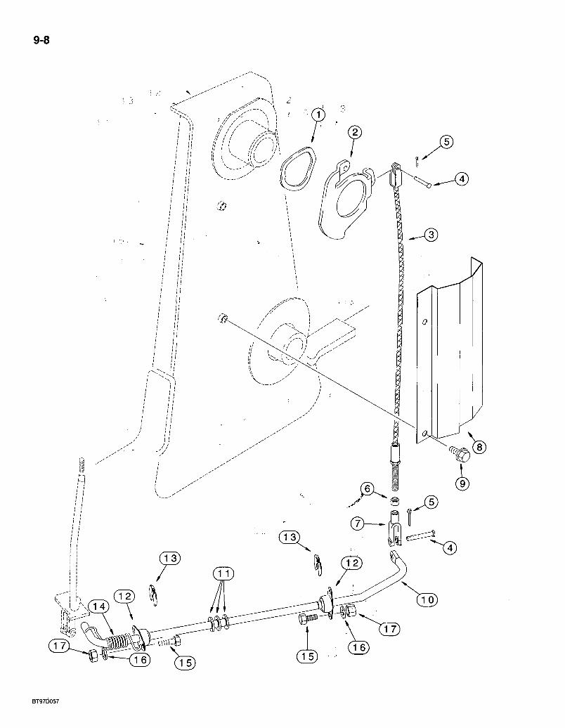
9-8
BT97D057
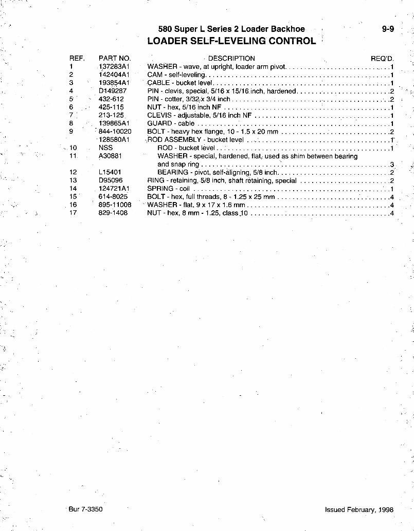
580 Super L Series 2 Loader Backhoe LOADER SELF-LEVELING CONTROL
9-9
REF. PART NO. 1 137283A1 2 142404A1 3 193854AT 4 D149287 5 432-612 6 , : 425-115 7 : 213-125 8 139865A1 9 844-10020
128580A1 10 NSS 11 A30881
12 LI 5401 13 D95096 14 124721A1 15 614-8025
. 16 895-11008 17 829-1408
DESCRIPTION REQ'D. WASHER - wave, at upright, loader arm pivot 1 CAM - self-leveling 1 CABLE - bucket level • • • -1 PIN - clevis, special, 5/16 x 15/16 inch, hardened 2 PIN - cotter, 3/32;x 3/4 inch .2 NUT - hex, 5/16 inch NF 1 CLEVIS - adjustable, 5/16 inch NF 1 GUARD-cab le 1 BOLT - heavy hex flange, 1 0 - 1 .5x20 mm 2 ;ROD ASSEMBLY - bucket level -T
ROD - bucket level -1 WASHER - special, hardened, flat, used as shim between bearing and snap ring 3 BEARING - pivot, self-aligning, 5/8 inch 2
RING - retaining, 5/8 inch, shaft retaining, special 2 SPRING-coi l .1 BOLT - hex, full threads, 8 - 1.25 x 25 mm 4 WASHER - flat, 9 X 17 x 1.6 mm 4 NUT - hex, 8 mm -1.25, class JO 4
Bur 7-3350 Issued February, 1998
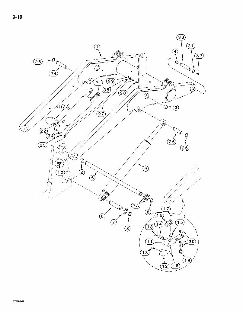
9-10
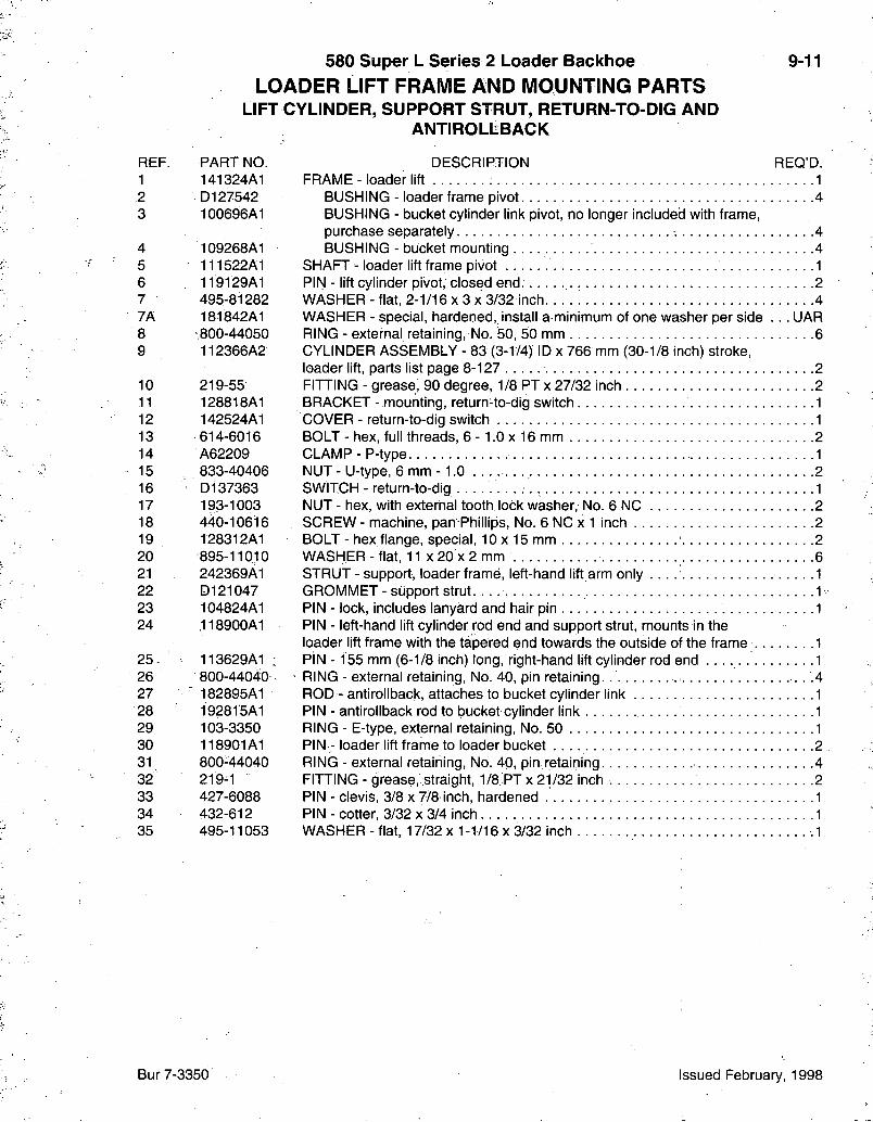
580 Super L Series 2 Loader Backlioe LOADER LIFT FRAME AND MOUNTING PARTS
LIFT CYLINDER, SUPPORT STRUT, RETURN-TO-DIG AND ANTIROLLBACK
9-11
REF. PART NO. 1 141324A1 2 D127542 3 100696A1
4 109268A1 5 111522A1 6 119129A1 7 - 495-81282 7A 181842A1 8 .800-44050 9 112366A2
10 219-55 11 128818A1 12 142524A1 13 614-6016 14 A62209 15 833-40406 16 D137363 17 193-1003 18 440-10616 19 128312A1 20 895-11010 21 242369A1 22 D121047 23 104824A1 24 ,118900A1
25 . 113629A1 26 800-44040 27 : 182895A1 28 192815A1 29 103-3350 30 118901A1 31 800-44040 32 219^1 33 427-6088 34 432-612 35 495-11053
DESCRIPTION REQ'D. FRAME - loader lift 1
BUSHING - loader frame pivot 4 BUSHING - bucket cylinder link pivot, no longer included with frame, purchase separately. 4 BUSHING - bucket mounting 4
SHAFT - loader lift frame pivot 1 PIN - lift cylinder pivot, closed end. 2 WASHER - flat, 2-1/16 x 3 x 3/32 inch. 4 WASHER - special, hardened,.install a minimum of one washer per side . . . UAR RING - external retaining. No. 30, 50 mm 6 CYLINDER ASSEMBLY - 83 (3-1/4) ID x 766 mm (30-1/8 inch) stroke, loader lift, parts list page 8-127 2 FITTING - grease, 90 degree, 1/8 PTx 27/32 inch 2 BRACKET - mounting, return-to-dig switch 1 COVER - return-to-dig switch 1 BOLT - hex, full threads, 6 -1 .0 x 16 mm . . 2 CLAMP - P-type 1 NUT-U-type, 6 m m - 1 . 0 2 SWITCH - return-to-dig 1 NUT - hex, with external tooth lock washer. No. 6 NC 2 SCREW - machine, pan Phillips, No. 6 NC x 1 inch 2 BOLT - hex flange, special, 10 x 15 mm 2 WASHER - flat, 11 x 20 x 2 mm 6 STRUT - support, loader frame, left-hand lift arm only . . . 1 GROMMET - support strut 1 PIN - lock, includes lanyard and hair pin 1 PIN - left-hand lift cylinder rod end and support strut, mounts in the loader lift frame with the tapered end towards the outside of the frame 1 PiN -155 mm (6-1/8 inch) long, right-hand lift cylinder rod end 1 RING - external retaining. No. 40, pin retaining. . .4 ROD - antirollback, attaches to bucket cylinder link 1 PIN - antirollback rod to bucket cylinder link 1 RING - E-type, external retaining. No. 50 1 PIN - loader lift frame to loader bucket 2 RING - external retaining, No. 40, pin retaining 4 FITTING - grease, straight, 1/8 PT x 21/32 inch 2 PIN - clevis, 3/8 x 7/8 inch, hardened 1 PIN - cotter, 3/32 x 3/4 inch .1 WASHER - flat, 17/32 x 1-1/16 x 3/32 inch .1
Bur 7-3350 Issued February, 1998
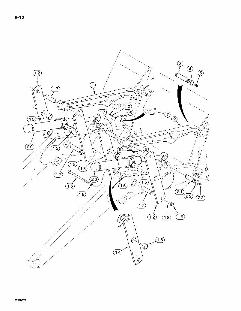
9-12
.,5
@
BT97N070
580 Super L Series 2 Loader Backhoe 9-13 LOADER FRAME BUCKET LINKS AND BUCKET CYLINDER LINKS
REF. . PART NO. 1 141471A1
2 141472A1
3 118901A1 4 800-44040 5 219-1 6 D121194 7 250851A1 8 614-8030 9 895-11008 10 892-11008 11 829-1408 12 139180A1
13 139235A1
14 139195A1
15 D151034 16 827-20190 17 D132076 18 896-11020 19 829-1420 20 113133A2
21 22 23
116339A1 800-44040 219-1
DESORIPTION REQ'D. LINK - bucket, left-hand, without mounting holes for bucket position pointer, used in production, for service order 141472A1 link, item 2 1 LINK - bucket, left-hand or right-hand, with mounting holes for bucket position pointer 1-2 PIN - bucket links to loader bucket 2 RING - external retaining. No. 40, pin retaining. | 4 FITTING - grease, straight, 1/8 PT x 21/32 inch 2 POINTER - bucket position, models without clam bucket 1 POINTER - bucket position, models with clam bucket 1 BOLT - hex, full threads, 8 - 1.25 x 30 mm 2 WASHER - flat, 9 x 17 x 1.6 mm 2; WASHER - lock, 8 mm 2 NUT-hex , 8 m m - 1.25, c l a s s i c .2 LINK - bucket cylinder, outer right-hand and inner and outer left-hand, includes item 15 bushing 3 LINK - bucket cylinder, inner right-hand, with extra hole for antirollback rod, includes item 15 bushing, models without clam bucket, see item-14 link for models with clam bucket 1 LINK - bucket cylinder, inner right-hand, with extra hole for antirollback rod, includes item 15 bushing, models with clam bucket, see item 13 for models without clam bucket 1
BUSHING - one per each link, items 12-14 1 BOLT - hex, 20 - 2.5 x 190 mm, class 10.9 4 BUSHING - spacer, cylinder links 4 WASHER - flat, 22 x 37 x 4 mm, hardened 8 NUT - hex, 20 mm -2 .5 , class 10 . . . . 4 OYLINDER ASSEMBLY - 76 (3) ID x 522 mm (20-9/16 inch) stroke, " loader bucket, parts list page 8-129 2 PIN - bucket cylinder rod end 2 RING - external retaining. No. 40, pin retaining 4 FITTING - grease, straight, 1/8 PT x 21/32 inch 2
Bur 7-3350• Issued February, 1998
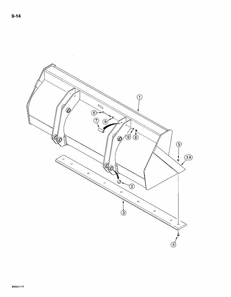
9-14
580 Super L Series 2 l:oader Backhoe L O A D E R LONG LIP B U C K E T
9-15
REF. PART NO. 141473A1
1 NSS 2 D129264 3 1 112946A1 3A : 113457A1 4 j 20-21232 5 429-1012 6 i 828-20160 -, 7 ' 142538A1 8 832-10420 9 896-11020
DESCRIPTION REQ'D. BUCKET ASSEMBLY - loader, without bucket teeth, order from Machinery Price List, 2083 mm (82 inch) wide 1
BUCKET - loader 1 BUSHING - bucket ear 8 EDGE - cutting, center, 2083 mm (82 inch) bucket .1 EDGE - cutting, weld-on, blade mounting 1 BOLT - plow, 3/4 NC X 2 inch, grade 8 10 NUT - hex, 3/4 inch NC, grade 8 10
BOLT - hex, 20 - 2.5 x 160 mm, class 10.9 2 SPACER - chain hook . 2 NUT - hex, self-locking, 20 mm - 2.5 2 WASHER - flat, 22 x 37 x 4 mm, hardened 4
Bur 7-3350 Issued February, 1998
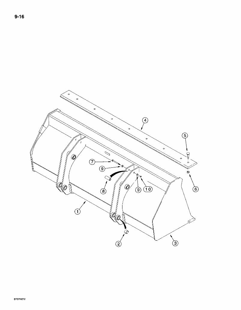
9-16
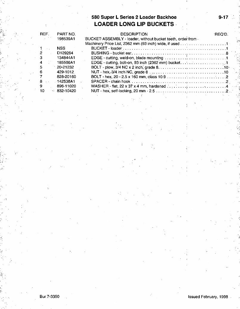
580 iSuper L Series 2 Loader Backhoe L O A D E R LONG LIP B U C K E T S
9-17
REF. PART NO. 198539A1
1 NSS 2 D129264 3 134844A1 4 185506A1 5 20-21232 6 429-1012 7 828-20160 8 142538A1 9 896-11020 10 832-10420
DESCRIPTION REQ'D. BUCKET ASSEMBLY - loader, without bucket teeth, order from Machinery Price List, 2362 mm (93 inch) wide, if used . . 1
BUCKET - loader 1 BUSHING - bucket ear ,. 8 EDGE - cutting, weld-on, blade mounting 1 EDGE - cutting, bolt-on, 93 inch (2362 mm) bucket. .1 BOLT - plow, 3/4 NG X 2 inch' grade 8. .10 NUT - hex,,3/4 inch NC, grade 8 10 BOLT - hex, 20 - 2.5 x 160 mm, class 10.9 2 SPACER - chain hook 2 WASHER - flat, 22 x 37 x 4 mm, hardened . . . . : ; -. 4 NUT - hex^self-locking, 20 mm - 2.5 2
Bur 7-3350 Issued February, 1998
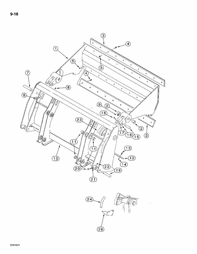
9-18
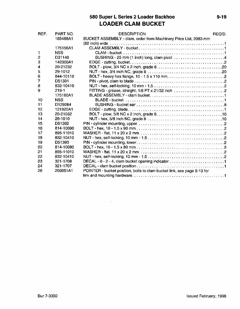
580 Super L Series 2 Loader Backhoe L O A D E R C L A M B U C K E T
9-19
REF. PART NO. 185488A1
175156A1 1 NSS 2 D31140 3 142300A1 4 20-21232 5 29-1012 6 844-10110 7 D51391 8 832-10410 9 219-1
175160A1 10 NSS 11 D129264 12 121920A1 13 20-21032 14 29-1010 15 D51392 16 814-10090 17 895-11010 18 832-10410 19 D51393 20 814-10080 21 895-11010 22 832-10410 23 321-1708 24 321-1707 26 250851A1
DESCRIPTION REQ'D. BUCKET ASSEMBLY - clam, order from Machinery Price List, 2083 mm (82 inch) wide 1
CLAM ASSEMBLY - bucket 1 CLAM-bucket 1 BUSHING - 25 mm (1 inch) long, clam pivot 4
EDGE - cutting, bucket 2 BOLT - plow, 3/4 NC X 2 inch, grade 8 20 NUT - hex, 3/4 inch NC, grade 8 20 BOLT - heavy hex flange, 10 -1 .5 x 110 mm 2 PIN - pivot, clam to blade 2 NUT - hex, self-locking, 10 mm -1 .5 2 FITTING - grease, straight, 1/8 PT x 21/32 inch 2 BLADE ASSEMBLY - clam bucket 1
BLADE-bucket 1 BUSHING - bucket ear 8
EDGE - cutting, blade 1 BOLT - plow, 5/8 NC X 2 inch, grade 8 10 NUT - hex, 5/8 inch NC, grade 8 10
PIN - cylinder mounting, upper 2 BOLT-hex , 1 0 - 1 .5x90 mm 2 WASHER - flat, 11 x 20 x 2 mm 2 NUT - hex, self-locking, 10 mm -1.5 2 PIN - cylinder mounting, lower 2 BOLT - hex, 10 -1 .5 x 80 mm 2 WASHER - flat, 11 x 20 x 2 mm 2 NUT - hex, self-locking, 10 mm -1 .5 2 DECAL -0-2-4, clam bucket opening indicator 1 DECAL - clam bucket position 1 POINTER - bucket position, bolts to clam bucket link, see page 9-13 for link and mounting hardware 1
Bur 7-3350 Issued February, 1998
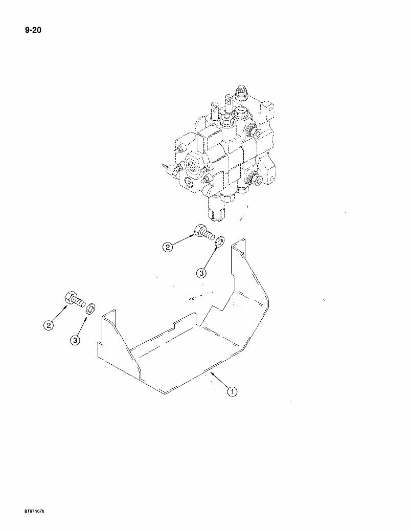
9-20
|- f
BT97N076
580 Super L Series 2 Loader Backhoe 9-21 L O A D E R V A L V E G U A R D
REF. PART NO. DESCRIPTION REQ'D. 1 238048A2 GUARD - valve shield, if used 1 2 614-10025 BOLT-hex , full threads, 1 0 - 1 . 5 x 2 5 mm , 2 3 . 896-11010 WASHER - flat, 11 x 21 x 2.5 mm, hardened 2
Bur 7-3350 Issued February, 1998

9-22
REF. PART NO.
1 *191239A1
h292969A2
580 Super L Series 2 Loader Backhoe T O O L QUICK C O U P L E R S
DESCRIPTION
*TOOL QUICK COUPLER, MANUAL
9-23
REQ'D.
COUPLER - tool, loader, manual, used with D121194 bucket position pointer and 139235A1 right-hand bucket cylinder link, Ref 6 and 13 on page 9-13, if used 1
TOOL QUICK COUPLER, HYDRAULIC
COUPLER - quick, tool, loader, hydraulic, component parts list not available at time of printing 1
* NOTE: Coupler comes complete, component parts are not serviced separately.
+ NOTE: See page 8-65 for hydraulic tool quick coupler hydraulics.
Bur 7-3350 Issued February, 1998

9-24
580 Super L Series 2 Loader Backhoe B A C K H O E C O N T R O L T O W E R C O V E R S
9-25
REF. •PART NO; 1 128403A1 2 130480A1
2A 253394A1
3 128401A1 4 -130479A1
4A 277187A1
5 353-411
6 281-1878 7- 281-18712 8 195-140 9 D149866 10 •D149867 11 136822A1 12 D149868 13 136824A1 14 140-106
15 131-623
16 277184A2 17 281.-14716 18 299383A1 19 353-408
DESCRIPTION REQ'D. COVER - rear, console, used on all models with foot swing COVER - console, front, used on models with foot swing, without auxiliary hydraulics COVER - console, front, used on models with foot swing, with auxiliary hydraulics COVER - console, rear, used on all models with hand swing COVER - front, console; used on models with hand swing, without auxiliary hydraulics COVER - console, front, used on models with hand swing] with auxiliary hydraulics PLUG - button, 1 inch, nylon, 1 used with 130479A1 console - 2 used with 130480A1 console cover 1-2 SCREW - self-tapping, hex washer head, 1/4 NC x 1/2 inch, lower .2 SCREW - self-tapping, hex washer head, 1/4 NC x 3/4 inch, upper 3 WASHER - flat, 9/32 x 5/8 x 1/16 inch 5 BOOT - used with 130480A1 console cover with 5 control levers BOOT - used with 130480A1 console cover with 6 control levers RETAINER - boot, used with items 9 and 10 BOOT - used with 13d479A1 console cover with 4 control levers RETAINER - boot, used with item 12 only SCREW - machine, pan head Phillips, No. 10 NC x 1/2 inch (4) used with 136822A1 retainer, (6) used with 136824A1 retainer 4-6 NUT - U-type, No. 10 NC (4) used with 136822A1 retainer, (6) used with 136824A1 retainer 4-6
MODELS WITH BACKHOE AUXILIARY HYDRAULICS
BRACKET - control lever .1 SCREW - self-tapping, hex washer head, 1/4 NC x 1 inch 2 DECAL - backhoe auxiliary hydraulic control 1 PLUG - button, 3/4 inch 1
Bur 7-3350 Issued February, 1998
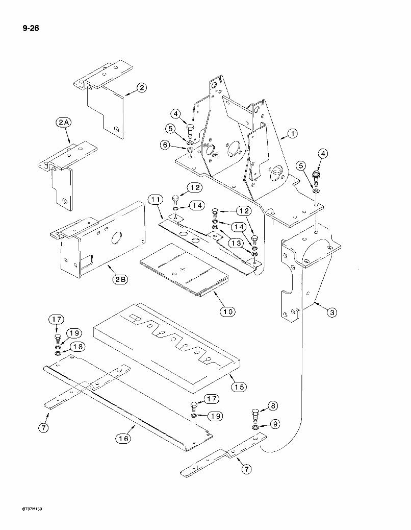
9-26
BT97N159
580 Super L Series 2 Loader Backhoe B A C K H O E C O N T R O L T O W E R S U P P O R T AND S E A L S
9-27
REF. PART NO. 1 185975A1
2 180376A1 2A ' 180402A1
2B 300580A1
3 121519A1 4 614-10035 5 496-41041 6 179956A1 7 184696A1 8 , 814-10060 9 496-41041 10 182295A1 11 184695A1 12 614-8020 13 895-11008 14 892-11008 15 :232875A1 16 184694A1 17 .. 614-6016 18 895-11006 19 892-11006
DESCRIPTION REQ'D. SUPPORT -. backhoe control mounting, with 3 mounting holes in base for item 11 seal support bracket 1 BRACKET - mounting, left-hand, 6 spool valve 1 BRACKET - mounting, left-hand, 7 spool valve, without auxiliary hydraulics 1 BRACKET - mounting, left-hand, 7 or 8 spool valve, with auxiliary hydraulics 1 BRACKET - mounting, right-hand, valve mounting 1 BOLT-hex , full threads, 1 0 - 1 . 5 x 3 5 mm 4 WASHER - flat, 13/32 x 1-1/8 x 9/64 inch, hardened 4 MOUNT - console 2 BRACKET - seal support, front 2 BOLT - hex, 10 -1 .5 x 60 mm 4 WASHER-f la t , 13/32 x 1-1/8 x 9/64 inch, hardened 4 SEAL - foam, control tower .1 BRACKET - seal support, front 1 BOLT - hex, full threads, 8 - 1.25 x 20 mm 3 WASHER - flat, 9 x 17 x 1.6 mm 2 WASHER - lock, 8 mm -3 SEAL - noise reduction, backhoe valve rods 1 BRACKET - seal support, rear -1 BOLT - hex, full threads, 6 -1 .0 x 16 mm 4 WASHER - flat, 6 . 6 x 1 2 x 1.6 mm 2 WASHER - lock, 6 mm 4
Bur 7-3350 Issued February, 1998
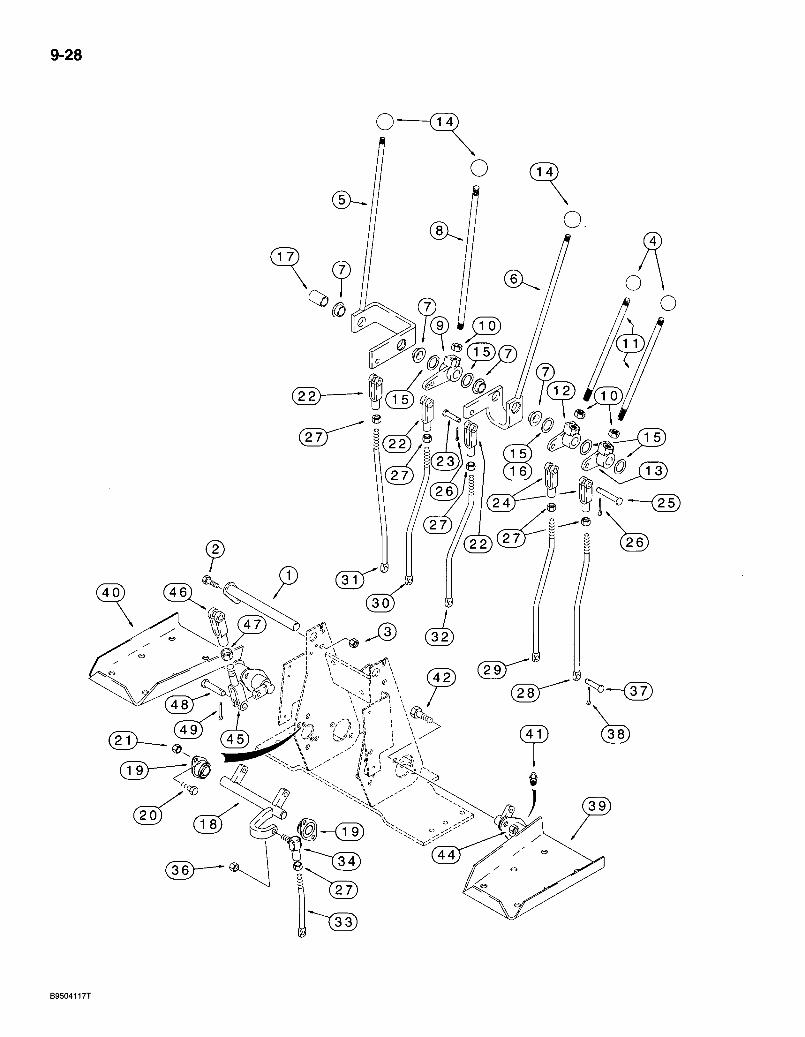
9-28
. J i - < 1 9 )
580 Super L Series 2 Loader Bacldioe B A C K H O E C O N T R O L S WITH F O O T SWING
WITH NON-EXTENDABLE DIPPER
9-29
REF. PART NO. 1 129015A1 2 614-8025 3 832-10408 4 D59912 5 136267A1 6 136269A1 7 D148992
8 136263A1 9 D150397 10 425-118 11 136261A1 12 -D150435 13 D150434 14 L54563 15 A30881:
16 D34666
17 . D150486 18 D148994 19 D148993 20 614-8025 21 832-10408 22 213-126 23 D14928.8 24 D150493 25 427-6088 26 432-612 27 425-156 28 189297A1 29 189296A1 30 , 189295A1 31 -189298A1 32 189294A1 33 189299A1
DESCRIPTION REQ'D. SHAFT - pivot, control levers. . 1 BOLT - hex, full threads, 8 - 1.25 x 25 mm . . . 1 NUT - hex, self-locking, 8 mm - 1.25 1 KNOB - lever, stabilizer control levers 2 LEVER - control, boom .1 LEVER - control, bucket 1
BUSHING - control lever, used with 136267A1 and 136269A1 control levers 2
LEVER - control, dipper. -1 • BELLCRANK - dipper control 1 NUT-hex , 1/2 inch NF . . . • • • -3 LEVER - control, stabilizer - 2 BELLCRANK - right-hand stabilizer con t ro l . . . 1 BELLCRANK - left-hand stabilizer control 1 KNOB - control lever, boom, dipper and bucket control levers 3 WASHER - special, hardened, flat, used as a shim between control levers UAR WASHER - flat, special, 3/4 inch, 3/4 inch, hardened, may be used in place of item 15 1 SPACER - control lever, not used on models with extendable dipper 1 SHAFT - swing control -1 BEARING - self-aligning, shaft 2 BOLT - hex, full threads, 8 - 1.25 x 25 mm 4 NUT - hex, self-locking, 8 mm - 1 . 2 5 . . 4 CLEVIS - adjustable, 3/8 inch NF 3 PIN - clevis, special 3 CLEVIS - 3/8 inch, stabilizer control rod, special 2 PIN - clevis, 3/8 x 7/8 inch, hardened 2 PIN - cotter, 3/32 x.3/4 inch . . . : .5 NUT - hex, jam, 3/8 inch NF 6 ROD - left-hand stabilizer control
right-hand stabilizer control dipper control boom control bucket control
ROD ROD ROD ROD ROD - swing control.
Continued on next page
Bur 7-3350 Issued February, 1998

9-30
a
.J i -<19)

580 Super L Series 2 Loader Backhoe BACKHOE CONTROLS WITH FOOT SWING
WITH NON-EXTENDABLE DIPPER
9-31
REF. PART NO. 34 D149295 36 425-116 37 D149287 38 , 432-612 , 39 136271 A t 40 136270A1 41 . 219-1 42 .614-10025 44 832-10410 45 D150503 46- D149262 47 425-156 . 48 D149288 49 432-612
DESCRIPTION REQ'D. JOINT - ball, swing control rod to shaft .1 NUT - hex, 3/8 inch NF • • • -1 PIN - clevis, special, 5/16 x 15/16 inch, hardened, rods to valve .6 PIN - cotter, 3/32 x 3/4 inch . . .\ . .6 PEDAL - left-hand swing 1 PEDAL - right-hand swing . . . . . . . .1 FITTING - grease, straight, 1/8 PTx 21/32 inch 2 BOLT - hex, full threads, 10 -1.5 x 25 mm . .4 NUT - hex, self-locking, 10 mm -1.5. . 4 ROD - with clevis, swing-pedal to cross shaft 2 CLEVIS - special, swing pedal rod . .2 NUT - hex, jam, 3/8 inch NF 2 PIN - clevis, special, swing pedal rod 4 PIN - cotter, 3/32 x 3/4 inch 4
Bur 7-3350 Issued February, 1998
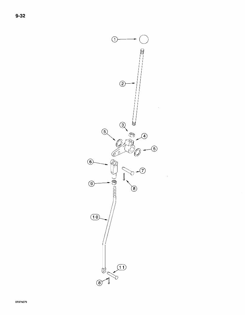
9-32
® — - o
BT97N079
580 Super L Series 2 Loader Backhoe BACKHOE CONTROLS WITH FOOT SWING
PARTS USED WITH EXTENDABLE DIPPER
9-33
REF. PART NO. 1 L54563 2 136263A1 3 425-118 4 182006A1 5 A3b881 6 213-126 7 427-6088 8 432-612 9 , 425-156 10 189293A1 11 D149287
DESCRIPTION REQ'D. KNOB - control lever, extendahoe LEVER - control, extendahoe NUT-hex, 1/2 inch NF BELLCRANK - extendahoe control lever WASHER - special, hardened, flat, spacer UAR CLEVIS - adjustable, 3/8 inch NF PIN - clevis, 3/8 x 7/8 inch, hardened PIN - cotter, 3/32 x 3/4 inch ; NUT - hex, jam, 3/8 inch NF ROD - extendahoe control lever to valve PIN - clevis, special, 5/16 x 15/16 inch, hardened, rod to valve . ,
Bur 7-3350 Issued February, 1998
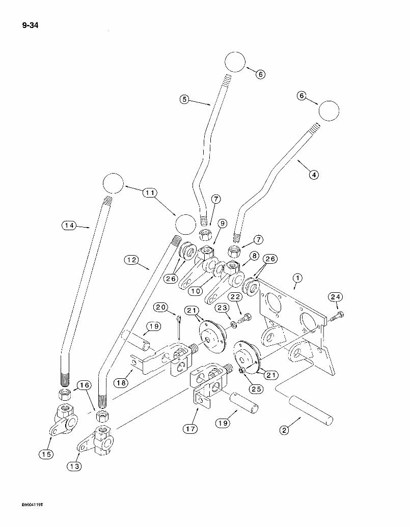
9-34
B9504119T
580 Super L Series 2 Loader Backhoe BACKHOE CONTROLS WITH HAND SWING
*UPPER CONTROL LEVERS WITH NON-EXTENDABLE DIPPER
9-35
REF. PART NO. 1 108864A1 2 D148947 4 109131A1 5 109132A1 6 D59912 7 425-118 8 108924A1 9 108923A1 10 495-11081 11 P39118 12 125113A1 13 ld6989Al 14 125113A1 15 106990A1 16 425-1110 17 178006A1 18 178004A1 19 : 102765A1 20 432- 828 21 112380A1 22 614-6016 23 396-41028 24 614-6020 25 ^ 829-1406 26 A3088i
D E S C R I P T I O N REQ 'D . P L A T E - mounting, bearing and bellcrank - .1 S H A F T - pivot, stabilizer lever 1 L E V E R - stabilizer, left-hand 1 L E V E R - stabilizer, right-hand 1 K N O B - lever, stabilizer levers 2 N U T - hex, 1/2 inch N F . : . . . .2 B E L L C R A N K - left-hand stabilizer lever .1 B E L L C R A N K - right-hand stabilizer lever , . .1 W A S H E R - f l a t , 13/16 x 1-15/32 x 1/8 inch .1 KNOB-control lever .2 L E V E R - control, boom and swing 1 B E L L C R A N K - left-hand boom and swing lever 1 L E V E R - control, bucket and dipper 1 B E L L C R A N K - right-hand bucket and dipper lever .1 N U T - hex, 5/8 inch N F .2 B E L L C R A N K - boom and swing control lever .1 B E L L C R A N K - bucket and dipper control lever 1 PIN ' - bellcrank 2 P I N - cotter, 1/8 x 1-3/4 inch 2 R E T A I N E R - bearing 4 B O L T - hex, full threads, 6 -1.0 x 16 mm 2 W A S H E R - flat, 9/32 x 7/8 x 3/32 inch, hardened 2 B O L T - hex, full threads, 6 --1.0 x 20 mm 6 N U T - hex, 6 mm -1.0, class 10 6 W A S H E R - special; hardened : UAR
* NOTE: See page 9-37 for lower control levers.
Bur 7-3350 Issued February, 1998
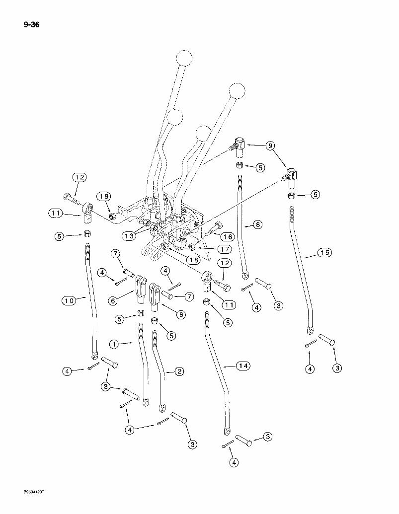
9-36
B9504120T
580 Super L Series 2 Loader Backhoe BACKHOE CONTROLS WITH HAND SWING
*LOWER CONTROL LEVERS WITH NON-EXTENDABLE DIPPER
9-37
REF. PART NO. DESCRIPTION REQ'D. 1 185981A1 ROD - stabilizer, right-hand stabilizer 1 2 185982A1 ROD - stabilizer, left-hand stabilizer . . • • • -1 3 D149287 PIN - clevis, special, 5/16 x 15/16 inch, hardened, rods toivalve .6 4 432-612 PIN - cotter, 3/32 x 3/4 inch 8 5 425-116 NUT-hex, 3/8 inch NF . . . . . . 6 6 213-126, CLEVIS - adjustable, 3/8 inch NF . . . . . 2 7 D149288 PIN - clevis, special. . . 2 8 185977A1 ROD - bucket control, 1 9 D149295 JOINT - ball, control rod -2 10 185978A1 ROD - dipper control 1 11 D136773 JOINT - ball, 3/8 inch NF, control rods 2 12 413-624 BOLT - hex, 3/8 NC x 1-1/2 inch 2 13 425-106 NUT- hex, 3/8 inch NC -2 14 185979A1 ROD - boom control 1 15 185980A1 ROD - swing control 1 16 614-10025 BOLT-hex, full threads, 10-1 .5x25 mm .2 17 832-10410 NUT-hex, self-locking, 10 mm-1.5 2 18 231-2446 NUT - hex, self-locking, 3/8 inch NF 2
* NOTE: See page 9-35 for upper control levers.
Bur 7-3350 • Issued February, 1998
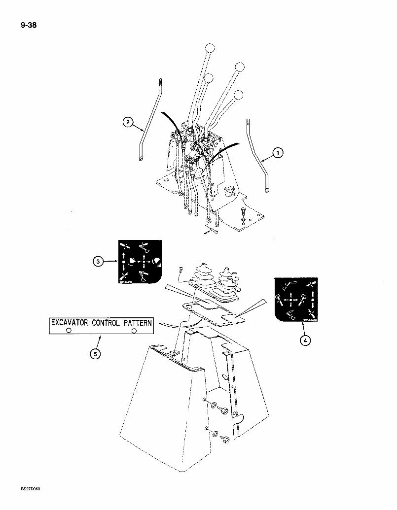
9-38
/ / 1 1 / / / / [// //7/
./.
EXCAVATOR CONTROL PATTERN O Q
BS97D060
580 Super L Series 2 Loader Backhoe BACKHOE CONTROLS
IN EXCAVATOR CONTROL PATTERN
REF. PARTNO. DESCRIPTION 245592A1 KIT - excavator control pattern, purchase from Parts and Components
1 * 195030A2 ROD - dipper, replaces existing, boom control rod 2 * 195032A1 ROD - boom, replaces existing dipper control rod 3 E49498 DECAL - control, right-hand 4 E49497 DECAL - control, left-hand 5 198410A1 PLATE r excavator control pattern
9-39
REQ'D.
* NOTE: The right-hand control lever, which used to control the dipper, now controls the boom and the left-hand control lever, which used to control the boom, now controls the dipper.
- NOTE: . The machine must be equipped with hand swing controls. If your machine is equipped with (Case) foot swing controls, the foot swing to hand swing controls field kit must be ordered and installed before installing this kit.
Bur 7-3350 Issued February, 1998

9-40
i
( T 2 >

580 Super L Series 2 Loader Bacl<hoe BACKHOE CONTROLS WITH HAND SWING
PARTS USED WITH EXTENDABLE DIPPER
9-41
REF. PART NO. 1 179029A1 2 126918A1 3 614-10025 4 832-10410 5 D143416 6 D134900 7 427-6088 8 432-612 9 425-156 10 185976A1 11 D149287 12 432-612 13 D150032 14 219-1
DESCRIPTION REQ'D. PEDAL - extendahoe control, right-hand ,.1 SUPPORT - pedal, with hole for tube and grease fitting 1 BOLT - hex, full threads, 10 -1.5 x 25 mm 2 NUT - hex, self-locking, 10 mm -1.5 .2 RING - retaining, clip ring, special 1 CLEVIS- special, 3/8 inch -1 PIN - clevis, 3/8 x 7/8 inch, hardened 1 PIN - cotter, 3/32x3/4 inch 1 NUT - hex, jam, 3/8 inch NF 1 ROD - extendahoe control 1 PIN - clevis, special, 5/16 x 15/16 inch, hardened, rod to valve 1 PIN - cotter, 3/32 x 3/4 inch 1 TUBE-pedal lube 1 FITTING - grease, straight, 1/8 PT x 21/32 inch 1
Bur 7-3350 Issued February, 1998
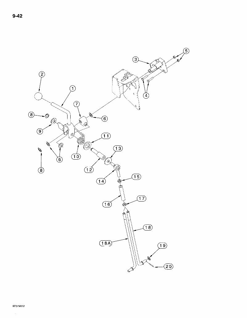
9-42
BT97M212

580 Super L Series 2 Loader Backhoe BACKHOE AUXILIARY HYDRAULIC CONTROL LEVER
9-43
REF. PART NO. DESCRIPTION REQ'D. 1 275820A3 LEVER - auxiliary control, detent lever, backhoe, uni-directional flow,
activates flow to the attachment through the use of the foot swjtch, see page 4-47 for foot switch 1
2 D59912 KNOB - lever 1 3 275677A1 SHAFT - pivot, 7 or 8 spool 1 4 614-6025 BOLT- hex, full threads, 6-1.0 x 25 mm ;. 2 5 829-1406 NUT - hex, 6 mm -1.0, class 10 2 6 195-81013 WASHER-flat, 33/64x7/8 1/32 inch, used as a shim 3 7 D136635 BLOCK - shifter pivot 1 8 103-3350 RING - E-type, external retaining. No. 50 2 9 495-11053 WASHER - flat, 17/32 x 1-1/16 x 3/32 inch 10 283226A1 SPRING - return 11 896-;11020 WASHER - flat, 22 x 37 x 4 mm, hardened 12 276070A1 SHAFT - spring pivot 13 495-81002 WASHER - flat, 7/16x1 -3/8 x 5/64 inch 14 R47941 JOINT - ball, male, 3/8 inch NF 15 • 425-156- NUT - hex, jam, 3/8 inch NF . 16 259410A1 TURNBUCKLE - hex 17 .129-289 NUT - hex, jam, 3/8 inch NF, left-hand thread 18 25781OAI ROD - control, 7 spool valve . 18A 283i332A1 ROD- control, 8 spool valve 19 895-18010 WASHER-flat, 11 X 18x1.6 mm 20 432-612 PIN - cotter, 3/32 X 3/4 inch
NOTE: See pages 8-51 - 8-55 for backhoe auxiliary hydraulics, page 4-47 for backhoe auxiliary electrical circuit and page 9-25 for the backhoe control tower cover used with auxiliary hydraulics.
Bur 7-3350 Issued February, 1998
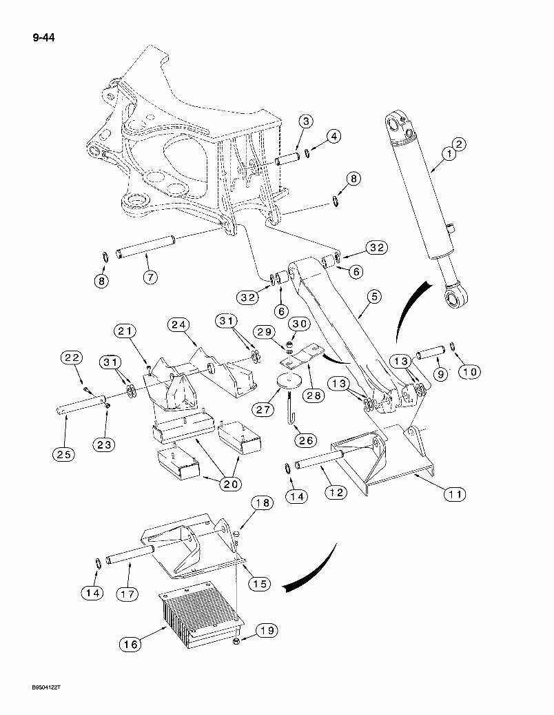
9-44
- o
1' I' ' " \ l >
B9504122T
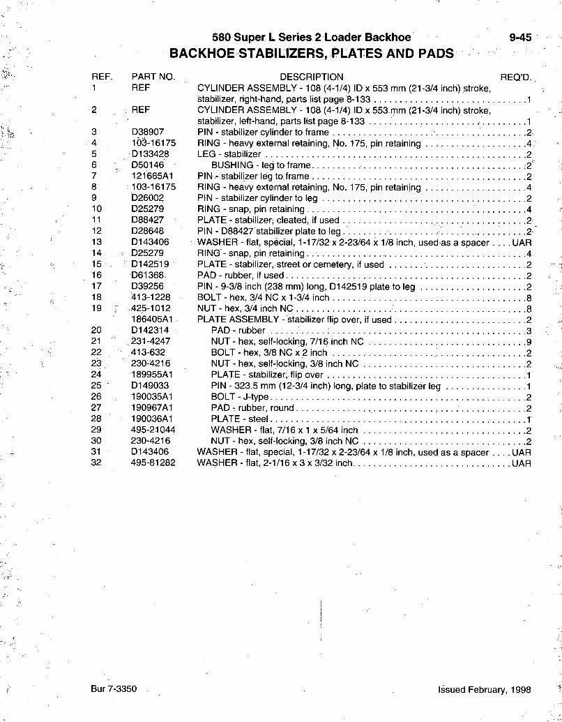
580 Super L Series 2 Loader Backhoe BACKHOE STABILIZERS, PLATES AND PADS
9-45
REF. PART NO. 1 REF
2 REF
3 D38907 4 103-16175 5 D133428 6 D5014& 7 121665A1 8 103-16175 9 b26002 10 D25279 11 D88427 12 D28648 13 D143406 14 D25279 15 '•' D142519 16 D61368 17 D39256 18 413-1228 19 • .425-1012
186405A1 20 D142314 21 .231-4247 22 413-632 23 230-4216 24 189955A1 25 " D149033 26 190035A1 27 190967A1 28 190036A1 29 495-21044 30 230-4216 31 D143406 32 495-81282
DESCRIPTION REQ'D. CYLINDER ASSEMBLY -108 (4-1/4) ID x 553 mm (21-3/4 inch) stroke, stabilizer, right-hand, parts list page 8-133 1 CYLINDER ASSEMBLY - 108 (4-1/4) ID x 553 mm (21-3/4 inch) stroke, stabilizer, left-hand, parts list page 8-133 1 PIN - stabilizer cylinder to frame 2. RING - heavy external retaining. No. 175, pin retaining .4 LEG - stabilizer 2
BUSHING - leg to frame -2' PIN - stabilizer leg to, frame -2 RING - heavy external retaining, No. 175, pin retaining .4 PIN - stabilizer cylinder to leg . 2 RING - snap, pin retaining 4 PLATE - stabilizer, cleated, if used -2 PIN - D88427 stabilizer plate to leg 2 WASHER - flat, special, 1-17/32 x 2-23/64 x 1/8 inch, used as a spacer UAR RING - snap, pin retaining 4 PLATE - stabilizer, street or cemetery, if used -2. PAD - rubber, if used 2 PIN - 9-3/8 inch (238 mm) long, D142519 plate to leg 2 BOLT - hex, 3/4 NC x 1-3/4 inch 8 NUT - hex, 3/4 inch NC 8 PLATE ASSEMBLY - stabilizer flip over, if used 2
PAD - rubber 3 NUT - hex, self-locking, 7/16 inch NC . . . 9 BOLT - hex, 3/8 NC x 2 inch 2 NUT - hex, self-locking, 3/8 inch NC 2 PLATE - stabilizer, flip over 1 PIN - 323.5 mm (12-3/4 inch) long, plate to stabilizer leg 1 BOLT-J-type 2 PAD - rubber, round 2 PLATE-steel 1 WASHER - flat, 7/16 x 1 x 5/64 inch 2 NUT - hex, self-locking, 3/8 inch NC 2
WASHER - flat, special, 1-17/32 x 2-23/64 x 1/8 inch, used as a spacer UAR WASHER - flat, 2-1/16 x 3 x 3/32 inch UAR
Bur 7-3350 Issued February, 1998
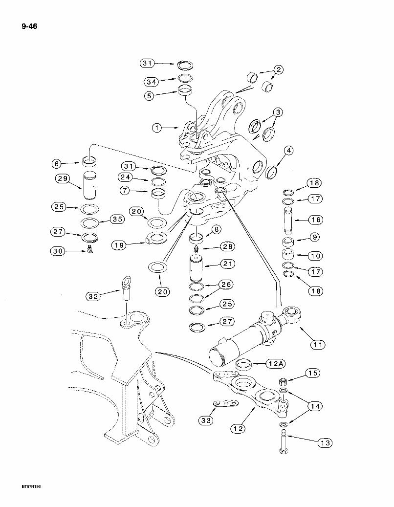
9-46
-A I -^^^ V ,
580 Super L Series 2 Loader Backhoe eio^CKHOE SWING CYLINDERS AND SWING TOWER
9-47
REF. PART NO. 1 249867A1 2 191017A1 3 121778A1 4 D135741 5 ,0135557 6 D135559 7 .,•151073 8 D151074 9 135248A1 10 135249A1 11 REF
12 198976A'1 12A • 114318A1 13 827-20075 14 896-11020 15 829-1420 16 135247A1 17 V 495-81227 18 103-16200 19 243084A1 20 134167A1 21 D151065 24 D136392 25 D136700 26 D136391 27 800-40065 28 219-1 29 292385A1 30 219,-55 31 ; 800r40070 32 D149239 33 197718A1
34 293636A1 35 D144423
DESCRIPTION REQ'D. TOWER ASSEMBLY- backhoe swing 1
BUSHING - boom cylinder pivot. . .2 , BUSHING - inner, boom pivot -2
BUSHING - outer, boom pivot 2 BUSHING - upper, swing tower pivot 1 BUSHING - upper, tower p ivot . . . . 1 BUSHING - tower pivot . . . . 1 BUSHING - 70 X 86 x 28 mm long, lower 1 BUSHING - upper, swing cylinder pivot 2 BUSHING -Mower, swing cylinder pivot 2
CYLINDER ASSEMBLY -102 (4) ID X 292 mm (11-1/2 inch) stroke, swing, parts list page 8-135 . 2 BRACKET - swing cylinder to frame 1
BUSHING - 80 mm ID, cylinder pivot . . .2 BOLT - hex, 20 - 2.5 x 75 mm, class 10.9 6 WASHER - fiat, 22 x 37 x 4 mm, hardened. 12 NUT - hex, 20 mm - 2.5, class 10 6 PIN - swing cylinder rod end to swing tower .2 WASHER - flat, 2-1/16 x 2-15/16 x 1/16 inch 4 RING - heavy external retaining. No. 200, pin retaining 4 WASHER - bearing, special, 5 mm thick, swing tower . . . . : 1 SHIM - 2.05 mm (.08 inch) thick : . . . UAR PIN - lower, swing tower to frame, grease fitting mounts in top of pin 1 SHIM - 72 x 89 X 3.0 mm, upper UAR SHIM-67 X 83 x2.0 mm .2 SHIM-72x89x 1 6 mm. . . . . . UAR RING - external retaining. No. 65, pin retaining, lower 2 FITTING - grease, straight, 1/8 PT x 21/32 inch 1 PIN - swing tower to frame, upper 1 FITTING - grease, 9Q degree, 1/8 PT x 27/32 inch 1 RING - external retaining. No. 70, pin retaining 2 PIN - swing stop, without snap ring 1 SHIM - swing cylinder spacer, use as required between bracket and ear of main frame, shims may be required on one end or both ends of bracket, if used • • • • UAR WASHER - flat, upper 1 WASHER - 2-5/8 x 3-3/8 x 1/8 inch, used as a shim UAR
Bur 7-3350 Issued February, 1998
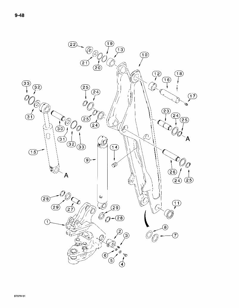
9-48

580 Super L Series 2 Loader Backhoe BACKHOE SWING TOWER AND BOOM
9-49
REF. PART NO. 1 REF
2 121779A1. 3 219-1 4 604-20040 5 496-41081 6 122897A1 7 H71514 8 R32119 9 144200A1
10 122284A1 11 D151071 12 ,,•135739
13 D137218
14 D120450 15 REF
16 D132494 17 219-1 18 300013A1 19 D136391 20 D136392 21 D133632 22 181042A1 23 123167A2 24 H433285 25 800-4155 26 123168A1 27 ^ 190313A1
DESCRIPTION REQ'D. SWING TOWER - backhoe, with inner ears, see page 9-47 for swing tower and bushings 1 PIN - swing tower to boom 2 FITTING - grease, straight, 1/8 PT x 21/32 inch 2 BOLT - hex, self-locking, 20 - 2.5 x 40 mm 2 WASHER - flat, 13/16 x 1-3/4 x 7/32 inch, hardened . .2, SPACER - 21 X 32 x'12 mm 2 WASHER - special, boom to swing tower UAR SHIM-71 (2-13/16) ID X 114 mm (4-1/2 inch) UAR CYLINDER ASSEMBLY -127 (5) ID x 842 mm (33-5/32 inch) stroke, boom, parts list page 8-137 .1 BOOM - backhoe, service replacement 1
BUSHING - 70 (2-3/4) ID x 34 mm (1-5/16 inc) long . . . . 2 BUSHING - 70.(2-3/4) ID x 44 mm (1-3/4 inch) long, with slot for groove pin, right-hand side of boom at boom to dipper pivot. . . .V BUSHING - 70 (2-3/4) ID x 44 mm (1-3/4 inch) long, without slot for groove pin, left-hand side of boom at boom to dipper pivot 1 PLUG - plastic 7
CYLINDER ASSEMBLY - 5 (127) ID x 23 inch (583 mm) stroke, dipper, parts list page 8-139 1 PIN - boom to dipper 1 FITTING - grease, straight, 1/8 PT x 21/32 inch 2 PIN - center groove, 1/2 x 3-1/4 inch, hardened .1 SHIM - 72 X 89 x 1.6 mm, boom to dipper UAR SHIM - 72 X 89 X 3.0 mm, boom to dipper UAR WASHER - flat, hardened, special 1 NUT - hex flange, special, 1-3/4 inch NF 1 PIN - dipper cylinder to boom, with center lubrication groove 1 SHIM -57x76 X 1.5 mm 4 RING - external retaining, No. 55, pin retaining 4 PIN - boom cylinder closed end to boom 1 PIN - boom cylinder rod end to swing tower .1
Continued on next page
Bur 7-3350 Issued February, 1998
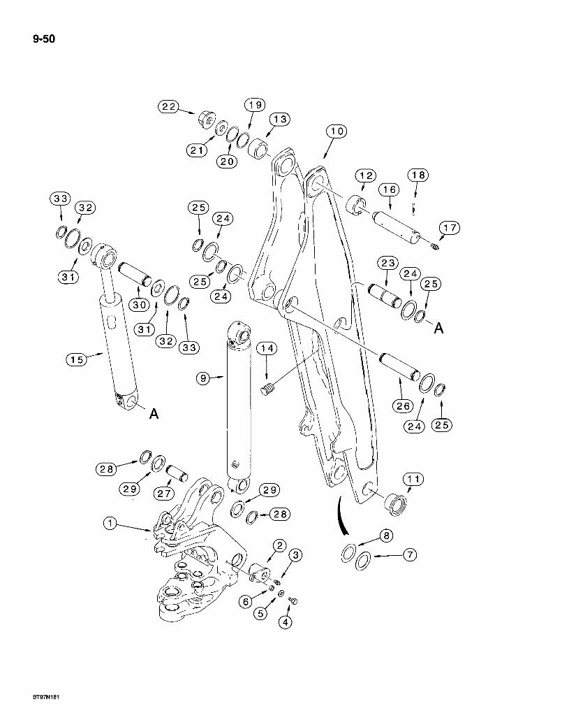
9-50
2 4 ) ( 2 5 )
580 Super L Series 2 Loader Backhoe 9-51 BACKHOE SWING TOWER AND BOOM
REF. - PART NO. DESCRIPTION REQ'D. 28 103-11237 RING - external retaining, No. 237, pin retaining 2 29 1233i8A1 WASHER - special, 62 mm ID UAR 30 D138022 PIN - clipper cylinder rod.end to dipper 1 31 495-81227 WASHER-flat, 2-1/16x2-15/16x1/16 inch UAR 32 495-81226 WASHER - flat, 1-13/16 x 2-1/2 x 1/8 inch . . ; 2 33 103-16175 RING - heavy external retaining. No. 175, pin retaining . . . . . . . 2
Bur 7-3350 Issued February, 1998
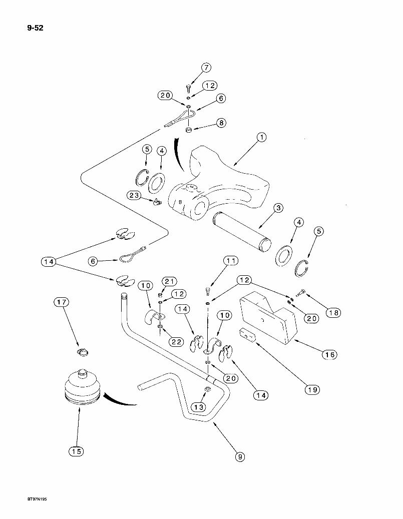
9-52
BT97Nig5
580 Super L Series 2 Loader Backhoe BOOM LATCH
9-53
REF. PART NO. 1 . 122974A1 3 D129227; 4 D144592 5 . 800-44040 6 D129641 7 614-10025 8 D143417 9 185632A2 10 D143723 11 614-10020 12 ' 892-11010 13 122958A1 14 D143591 15 D86664 16 122995A1 17 . D143735 18 614-10050 19 122993A1 20 895-11010 21 829-1410 22 896-11012 23 219-55
DESCRIPTION REQ'D. LATCH - backhoe boom 1 PIN - boom latch to swing tower 1 WASHER - flat, special • -2 RING - external retaining, No. 40, pin retaining 2 CABLE - latch control 1 BOLT - hex, full threads, 10 -1.5 x 25 mm • • 1 SPACER -10 ID X 16 OD X 6 mm long 1 ROD - boom latch control 1 CLAMP - rod 2 BOLT - hex, full threads, 10 -1.5 x 20 mm 1 WASHER-lock, 10mm 4 NUT - square, special, 10 mm -1 .5 . : .1 RETAINER - clip ring -4 BOOT-rod 1 BUMPER-boom. , • • • • • 1 CLAMP-boot 1 BOLT - hex, full threads, 10 -1.5 x 50 mm 1 PLATE - boom stop • • V WASHER-flat, 11 x 20x2 mm • • • 3 NUT - hex, 10 mm -1.5, class 10.9 1 WASHER - flat, 13.5 x 24 x 3 mm, hardened . . . .1 FITTING - grease, 90 degree, 1/8 PT x 27/32 inch 1
Bur 7-3350 Issued February, 1998
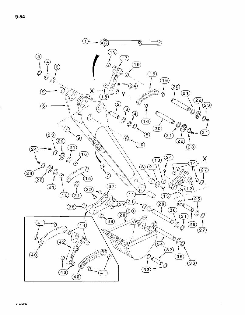
9-54
5
( 30 ) - ( ^ f ? ^ I ( 3 0
580 Super L Series 2 Loader BacUnoe BACKHOE DIPPER AND BUCKET
9-55
REF. PART NO. 1 REF
2 D138022 3 495-81227 4 495-81226 5 103-16175
101631A1 6 NSS 7 D120450 8 D140029 9 D138047
10 D150121
11 D127168
134437A1
12 NSS 13 D127167 14 D127172 15 D150608
16 D150122 17 D150080
18 D127172 19 D138047 20 D141142 21 495-81282 22 D141164 23 103-16175 24 219-1 25 495-81226 26 D146288 27 103-16175 28 REF
DESCRIPTION REQ'D. CYLINDER ASSEMBLY - 80 (3-1/2) ID x 872 mm (34-5/16 inch) stroke, bucket, parts list page 8-141 1 PIN - bucket cylinder closed end to dipper 1 WASHER - flat, 2-1/16 x 2-15/16 x 1/16 inch UAR WASHER - flat, 1-13/16 x 2-1/2 x 1/8 inch 2 RING - heavy external retaining. No. 175, pin retaining 2 DIPPER ASSEMBLY - backhoe 1
DIPPER - backhoe 1 PLUG - plastic 6 BUSHING - 50 x 60 X 25.5 mm long 2
BUSHING - 54 mm (2-1/8 inch) long, dipper cylinder rod end, not included with dipper assembly, order separately 2 BUSHING - 70 ID X 36 mm long, not included with dipper assembly, order separately 2 BUSHING - 45 ID X 94 mm long, bucket coupler pivot, not included with dipper assembly, order separately 2 COUPLER ASSEMBLY - bucket, used with Ref 15 and 17 links, if used, see Ref 37 - 44 for optional coupler and links 1
COUPLER - backhoe bucket 1 BUSHING - 30 mm long, special, at dipper 2 BUSHING - 28 mm long, at bucket link 4
LINK - bucket guide, used with 134437A1 coupler, if used, see Ref 37 -44 for optional coupler and links 2
BUSHING - 50 X 60 X 33 mm 2 LINK - bucket dump, with two bushings at forked end, used with 134437A1 coupler, if used, see Ref 37 - 44 for optional coupler and links 1
BUSHING-28 mm long 2 BUSHING - 54 mm (2-1/8 inch) long 2
PIN-306 mm long 2 WASHER - flat, 2-1/16 x 3 x 3/32 inch UAR SPACER -1-13/16 x 3 x 1/8 inch 4 RING - heavy external retaining. No. 175, pin retaining 4 FITTING - grease, straight, 1/8 PT x 21/32 inch 6 WASHER - flat, 1-13/16 x 2-1/2 x 1/8 inch 2 PIN - dump link to bucket coupler 1 RING - heavy external retaining. No. 175 2 BUCKET - backhoe, see pages 9-63 - 9-71 for bucket options 1
Continued on next page
Bur 7-3350 Issued February, 1998

9-56
0. - ( 2 4 ) ~
0
39) (3 ]X^^ ( 2 9 ( 3 0 )— • P r - . T ( 3 0 0
BT97D063
580 Super L Series 2 Loader Baclthoe BACKHOE DIPPER AND BUCKET
REF. PART NO. ^ 29 D37614
30 D143324 31 D25279 32 D149298 33 103-16175 34 D150619
35 495-81226 36 103-16175
281185A1
37 NSS 38 D127167 39 D127172 40, 242562A1 41 D150122 42 242561A1 43 D127172 44 D138047
9-57
REQ'D. DESCRIPTION PIN - bucket to coupler 1 WASHER - spacer, 38 x 64 x 2 mm 2 RING - snap, pin retaining 2 PIN - dipper to bucket, 305 mm (12 inch) Universal bucket only 1 RING - heavy external retaining. No. 175, pin retaining 2 PIN - dipper to bucket, all buckets except 12 inch (305 mm) buckets, for models with 12 inch bucket see item 32 pin .1 WASHER - flat, 1-13/16 x 2-1/2 x 1/8 inch UAR RING - heavy external retaining. No. 175, dipper to bucket pin 2 COUPLER ASSEMBLY - bucket, may replace 134437A1 (Ref 12) coupler on some models, used with Ref 40 and 42 links, if used 1
COUPLER - bucket, if used 1 BUSHING - 30 mm long, special, at dipper 2 BUSHING - 28 mm long, at bucket link .4
LINK - bucket guide, used with 281185A1 coupler, if used 2 BUSHING - 50 X 60 X 33 mm 2
LINK - bucket dump, used with 281185A1 coupler, if used.: 1 BUSHING - 28 mm long 2 BUSHING - 54 mm (2-1/8 inch) long 2
Bur 7-3350 Issued February, 1998
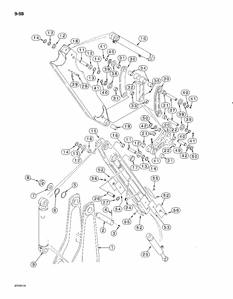
9-58
3 9 ) I ^ / ^ ; ^ X l 4 )
0
C>^<T9) ( 4 2 ) £ @
580 Super L Series 2 Loader Baclclioe EXTENDABLE DIPPER
9-59
REF. PART NO. 1 REF 2 D132494 3 219-1 4 435-51652 5 D13639r 6 D136392 7 D133632 8 181042Ai 9 REF
10 REF
11 • D141666 12 495-81227 13 495-81226 14 103-16175
140453A1
15-. ^'NSS 16 . D149079 17 D150121 18 102649A1 19 D127168
*134437A1
20 : N S S 2V , D127167 22 D127172 24 D133865 25 1340969C2
26 .300588A1 27 800-44040 28 D140247
29 A33509 30 *D150608
31 .D150122 32 *D150080
33 D127172 34 D138047
DESCRIPTION REQ'D. BOOM - backhoe, see page 9-49 for boom and bushings 1 PIN - boom to dipper 1 FITTING - grease, straight, 1/8 PT x 21/32 inch 2 PIN - center groove, 1/2 x 3-1/4 inch, hardened 1 SHIM - 72 x 89 X 1.6 mm, boom to dipper J 2;. SHIM - 72 X 89 x 3.0 mm; . . . .1 WASHER - flat, hardened, speciai".. .1 NUT - hex flange, .special, 1-3/4 inch NF. . . 1 CYLINDER ASSEMBLY - 5 (127) ID x 23 inch.(583 mm) stroke, dipper, parts list page 8-139 1 CYLINDER ASSEMBLY - 80 (3-1/2) ID x 872 mm (34-5/16 inch) stroke, bucket, parts list page 8-141 1 PIN - dipper and bucket cylinder to dippers ! 2 WASHER - flat, 2-1/16 x 2-15/16 x 1/16 inch UAR WASHER - flat, 1-13/16 x 2-1/2 x 1/8 inch 4 RING - heavy external retaining. No. 175, pin retaining 4 DIPPER ASSEMBLY - extension, inner, uses wear plates (Ref 52-54) with one mounting hole 1 DIPPER-inner 1 BUSHING - 50 X 34 mm long, dipper cylinder rod end pivot 2 BUSHING - 70 ID X 36 mm long, to dipper pivot 2 HOUSING - dipper, outer 1 BUSHING - 45 ID x 94 mm long, bucket coupler pivot 2 COUPLER ASSEMBLY - bucket, used with Ref 30 and 32 links, if used, see note 1
COUPLER - backhoe bucket . .1 BUSHING - 30 mm long, special, at dipper 2 BUSHING - 28 mm long, at bucket link 4
PLUG - plastic A CYLINDER ASSEMBLY - 76 (3) ID x 1068 mm (42 inch) stroke, dipper extension, parts list page 8-143.. .1 PIN - dipper extension cylinder closed end 1 RING - external retaining. No. 40, pin retaining .2 PIN - lock, used at dipper extension cylinder closed end when transporting only, used with item 29 lock pin ! 1 PIN - lock, 7/16 inch diameter 1 LINK - 33 mm wide bushing, bucket guide, used with 134437A1 coupler, if used, see note 2
BUSHING - 50 X 60 x 33 mm . . . . . . . .2 LINK - bucket dump, with two bushings at forked end, usediwith 134437A1 coupler, if used, see note 1
BUSHING - 28 mm long . . 2 BUSHING - 54 mm (2-1/8 inch) long 2
* NOTE: See page 9-57, Ref 37-44 for optional coupler and bucket links.
Continued on next page
Bur 7-3350 Issued February, 1998
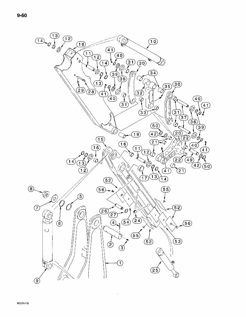
9-60
3 i ; r 3 o
0
71 0
BT97N176
580 Super L Series 2 Loader Backhoe EXTENDABLE DIPPER
9-61
REF. PART NO. 35 219-1 37 D141142 38 495-81282 39 D141164 40 : 103-16175 41 219-1 42 495-81226 48 409-768 49 , D146288 50 103-16175 52 132716A1 53 132844A1 54 132842A1 55 183443A1 56 D143242
DESCRIPTION REQ'D. FITTING - grease, straight, 1/8 PT x 21/32 inch 1 PIN - 306 mm long, bucket cylinder rod end to links and links to dipper 2 WASHER - flat, 2-1/16 x 3 x 3/32 inch 4 SPACER-1-13/16x3x1/8 inch 4 RING - heavy external retaining. No. 175, pin retaining 4 FITTING - grease, straight, 1/8 PT x 21/32 inch .5 WASHER-flat, 1-13/16 x 2-1/2 x 1/8 inch 2. BOLT - hex serrated flange, 3/8 NC x 1/2 inch .4 PIN - dump link to bucket coupler 1 RING - heavy external retaining. No. 175 -2 PLATE - wear, outer 4 SHIM - 0.8 mm thick, wear plate UAR SHIM -1.6 mm thick, wear plate UAR PIN - pine tree, long 2 RETAINER - push-in, plastic 2
Bur 7-3350 Issued February, 1998
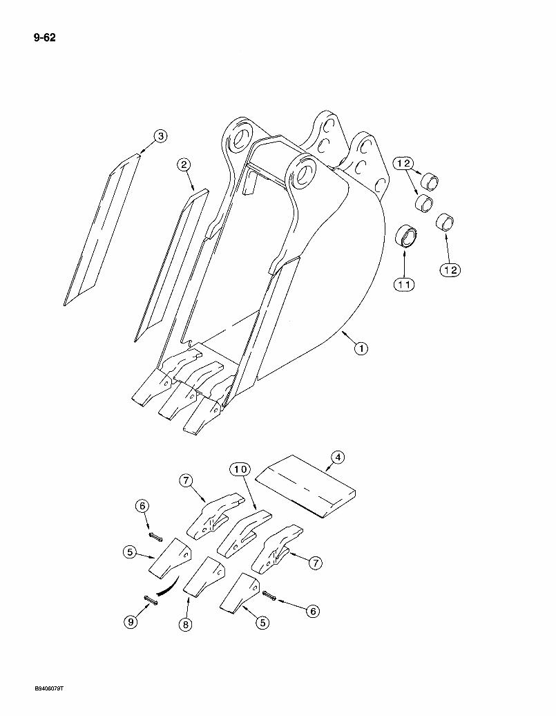
9-62
B9406079T
REF. P A R T NO.
580 Super L Series 2 Loader Backhoe UNIVERSAL BACKHOE BUCKET
305 MM (12 INCH) WIDE
D E S C R I P T I O N
9-63
R E Q ' D .
305 MM (12 INCH) WIDE TRENCHING BUCKET AND TEETH - HEAVY DUTY
1 * D 1 4 7 4 1 8
2 D147411 3 D147410 4 D147409
D139851 5 D39093 6 245466A1 7 D138157
D139849 8 D51750 9 245466A1 10 D48212 11 D40243 12 D30933
B U C K E T A S S E M B L Y - heavy duty t rench ing , wi th 3 tee th , order f r om Machinery Price List, 305 m m (12 inch) w ide
E D G E - cut t ing, r ight -hand s ide, bucket E D G E - cut t ing, lef t -hand s ide, bucket E D G E - cut t ing, center, 305 m m (12 inch) bucket T O O T H A S S E M B L Y - outer corners
POINT - too th , outer corners P IN - f lex, outer point a n d shank S H A N K - too th , outer corners ^
T O O T H A S S E M B L Y - center (order i tems 8-10) P O I N T - t o o t h , center . PIN - f lex, center point and shank . S H A N K - too th , center
B U S H I N G - 1-3/4 x 2-1/4 x 3/4 inch . 2 B U S H I N G - 1 - 1 / 2 X 1-7/8 X 1-1/4 inch 6
* N O T E : - S e e i tem 32 on page 9-57 for pin used on 12 inch Universal bucket .
Bur 7^3350 Issued February, 1998
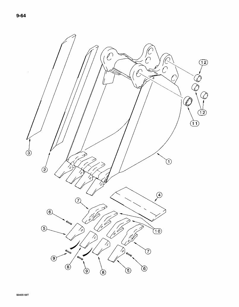
9-64
c.
B9405166T
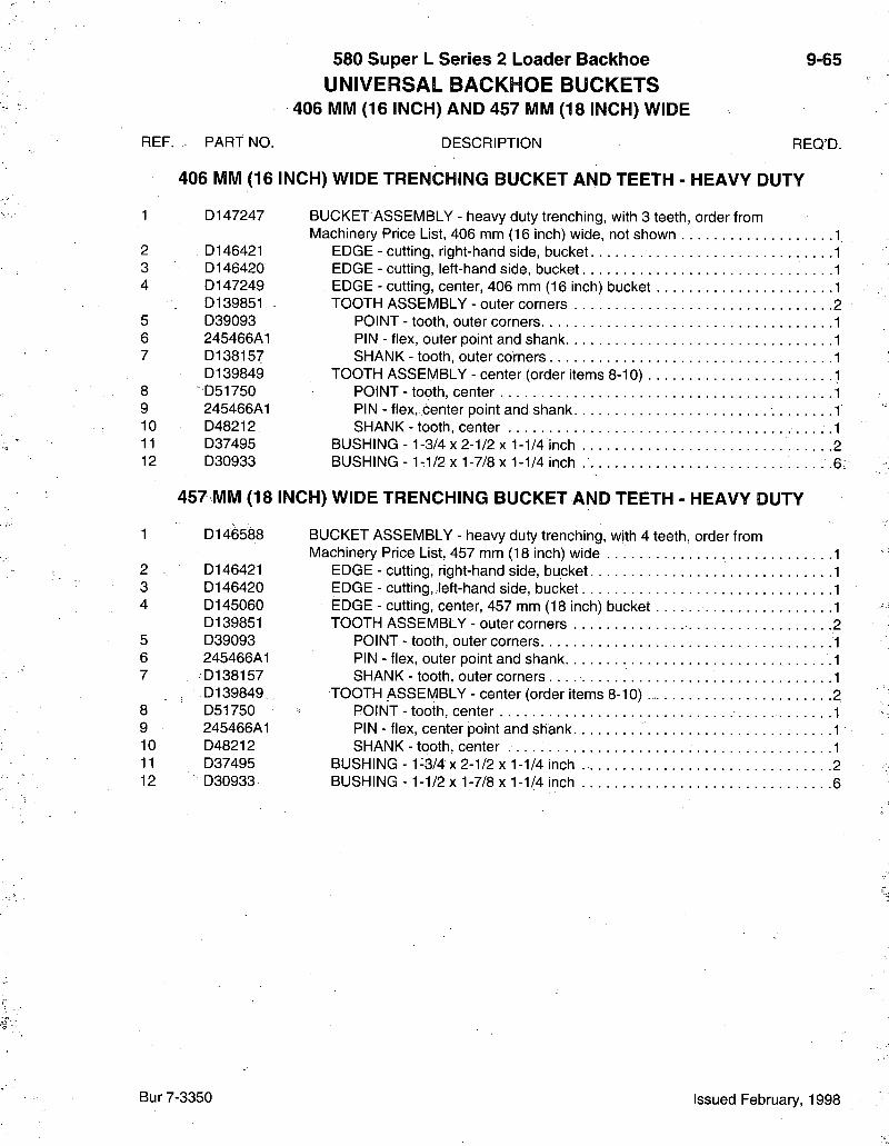
REF. P A R T NO.
580 Super L Series 2 Loader Backhoe UNIVERSAL BACKHOE BUCKETS
406 MM (16 INCH) AND 457 MM (18 INCH) WIDE
D E S C R I P T I O N
9 65
R E Q ' D .
406 MM (16 INCH) WIDE TRENCHING BUCKET AND TEETH - HEAVY DUTY
B U C K E T A S S E M B L Y - heavy duty t rench ing , wi th 3 tee th , order f rom Mach inery Pr ice List, 406 m m (16 inch) w ide , not shown .1
E D G E - cut t ing, r ight -hand s ide, bucket E D G E - cut t ing, lef t -hand s ide, bucket E D G E - cut t ing, center , 4 0 6 m m (16 inch) bucket T O O T H A S S E M B L Y - outer corners
POINT - too th , outer corners PIN - f lex, outer point and shank S H A N K - too th , outer corners
T O O T H A S S E M B L Y - center (order i tems 8-10) P O I N T - tooth , center PIN - f lex, center point and shank S H A N K - tooth , center
B U S H I N G - 1-3/4 x 2-1/2 x 1-1/4 inch . 2 B U S H I N G - 1 - 1 / 2 x 1 - 7 / 8 x 1-1/4 inch -6
1 D147247
2 D146421 3 D146420 4 D147249
D139851 5 D39093 6 245466A1 7 D138157
D139849 8 D51750 9 245466A1 10 D48212 11 D37495 12 D30933
457 MM (18
1 D146588
2 D146421 3 D146420 4 D145060
D139851 5 D39093 6 245466A1 7 D138157
D139849 8 D51750 9 245466A1 10 D48212 11 D37495 12 D30933
457 MM (18 INCH) WIDE TRENCHING BUCKET AND TEETH - HEAVY DUTY
B U C K E T A S S E M B L Y - heavy duty t rench ing , wi th 4 tee th , order f rom Machinery Price List, 457 m m (18 inch) w ide
E D G E - cut t ing, r ight -hand s ide, bucket E D G E - cut t ing, lef t -hand s ide, bucket E D G E - cut t ing, center, 457 m m (18 inch) bucket T O O T H A S S E M B L Y - outer corners
POINT - tooth , outer corners P IN - f lex, outer point and shank S H A N K - tooth , outer corners
T O O T H A S S E M B L Y - center (order i tems 8-10) P O I N T - t o o t h , center PIN - f lex, center point and s h a n k . . S H A N K - t o o t h , center . .
B U S H I N G - 1-3/4 x 2-1/2 x 1 -1/4 inch 2 B U S H I N G - 1-1/2 X 1-7/8 x 1-1/4 inch 6
Bur 7-3350 Issued February, 1998

9-66
&
B9406055T

REF. P A R T NO.
580 Super L Series 2 Loader Backhoe UNIVERSAL BACKHOE BUCKETS
610 MM (24 INCH) AND 762 MM (30 INCH) WIDE
D E S C R I P T I O N
9-67
R E Q ' D .
610 MM (24 INCH) WIDE TRENCHING BUCKET AND TEETH - HEAVY DUTY
B U C K E T A S S E M B L Y - heavy duty t rench ing , wi th 5 tee th , order f rom Machinery Price List, 610 m m (24 inch) w ide
E D G E - cut t ing, r ight -hand s ide, bucket E D G E - cut t ing, lef t -hand s ide, bucket E D G E - cut t ing, center , 6 1 0 m m (24 inch) bucket T O O T H A S S E M B L Y - outer corners
P O I N T - too th , outer corners PIN - f lex, outer point and shank S H A N K - too th , outer corners
T O O T H A S S E M B L Y - center (order i tems 8-10) 3 P O I N T - tooth , center PIN - f lex, center point and shank S H A N K - tooth , center
B U S H I N G - 1-3/4 x 2-1/2 x 1-1/4 inch - 2 B U S H I N G - 1 - 1 / 2 x 1-7/8 x 1-1/4 inch 6
762 MM (30 INCH) WIDE TRENCHING BUCKET AND TEETH - HEAVY DUTY
B U C K E T A S S E M B L Y - heavy duty t rench ing, with 5 tee th , order f rom Machinery Price List, 762 m m (30 inch) w ide , not shown
E D G E - cut t ing, r ight-hand s ide, bucket E D G E - cut t ing, lef t -hand s ide, bucket E D G E - cut t ing, center , 7 6 2 m m (30 inch) bucket T O O T H A S S E M B L Y - outer corners
P O I N T - too th , outer co rners PIN - f lex, outer point and shank S H A N K - too th , outer corners
T O O T H A S S E M B L Y - center (order i tems 8-10) P O I N T - too th , center PIN - f lex, center point and shank S H A N K - tooth , center
B U S H I N G - 1-3/4 x 2-1/2 x 1-1/4 inch .2 B U S H I N G - 1-1/2 x 1-7/8 x 1-1/4 inch 6
1 D150348
2 D146421 3 D146420 4 D142012
D139851 5 D39093 6 245466A1 7 D138157
0 1 3 9 8 4 9 8 D51750 9 245466A1 10 D48212 11 D37495 12 D30933
762 MM (30
1 D150364
2 D146421 3 D146420 4 D145061
D139851 5 D39093 6 245466A1 7 - D138157
D139849 8 D51750 9 ,245466A1 10 ' D 4 8 2 1 2 11 D37495 12 D30933
Bur 7-3350 Issued February, 1998

9-68
B9406053T

REF. P A R T NO.
580 Super L Series 2 Loader Backhoe UNIVERSAL BACKHOE BUCKETS
914 MM (36 INCH) WIDE
D E S C R I P T I O N
9-69
R E Q ' D .
914 MM (36 INCH) WIDE TRENCHING BUCKETS AND TEETH - HEAVY DUTY
B U C K E T A S S E M B L Y - heavy duty t rench ing , wi th 7 tee th , order f rom Mach inery Price List, 914 m m (36 inch) w ide
E D G E - cut t ing, r ight-hand s ide, bucke t . . . ! E D G E - cut t ing, lef t -hand s ide, bucket E D G E - cut t ing, center, 914 m m (36 inch) bucket T O O T H A S S E M B L Y - outer corners
POINT - tooth , outer corners P IN - f lex, outer point and shank S H A N K - t o o t h , outer corners
T O O T H A S S E M B L Y - center (order i tems 8-10) POINT - too th , center P IN - f lex, center point a n d shank S H A N K - t o o t h , center
B U S H I N G - 1-3/4 x 2-1/2 x 1-1/4 inch 2 B U S H I N G - 1-1/2 X 1-7/8 x 1-1/4 inch 6
1 D150365
2 D146421 3 D146420 4 D145062
D139851 5 D39093 6 245466A1 7 D138157
D139849 8 * D51750 9 245466A1 10 D48212 11 D37495 12 D30933
B u r 7 - 3 3 5 0 Issued February, 1998
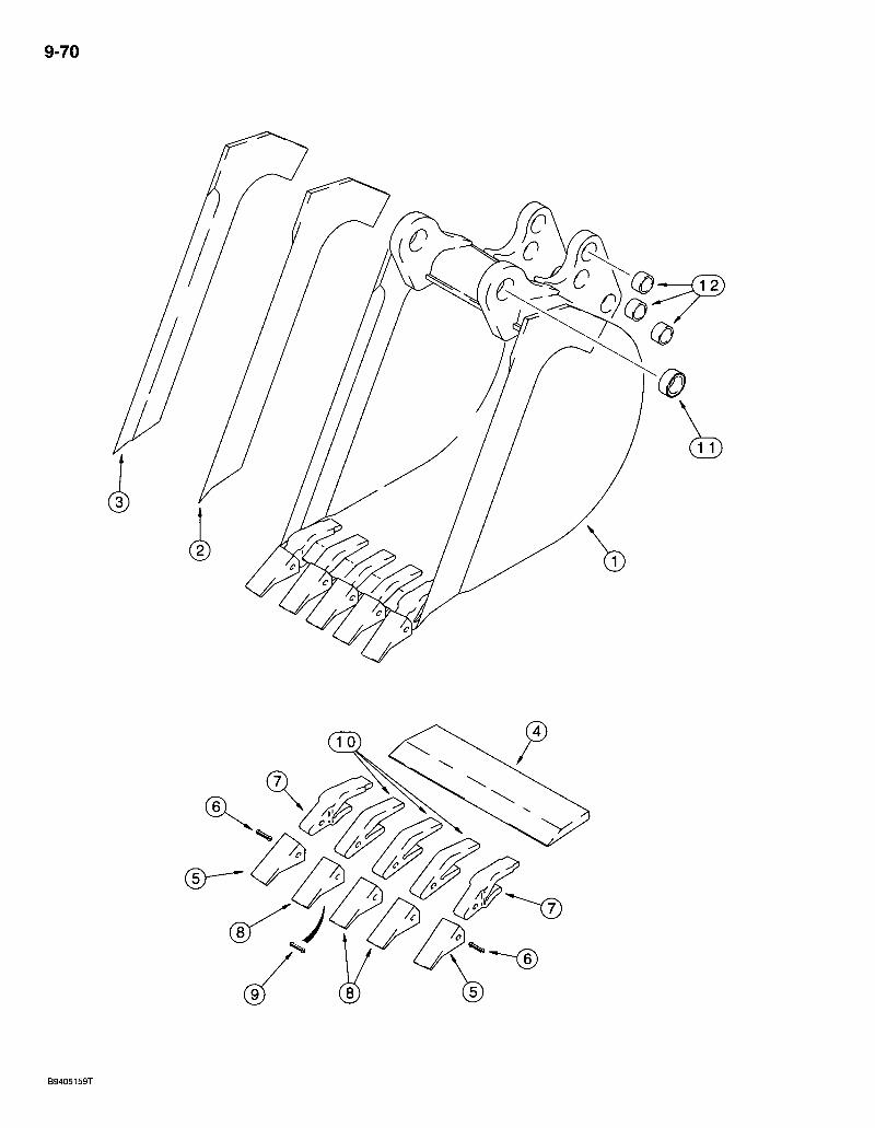
9-70

REF. P A R T NO.
580 Super L Series 2 Loader Backhoe UNIVERSAL BACKHOE BUCKET
610 MM (24 INCH) AND 762 MM (30 INCH) WIDE
D E S C R I P T I O N
9-71
R E Q ' D .
1 141232A1
2 141234A1 3 141233A1 4 D142012
D139851 5 D39093 6 24'5466A1 7 D138157
D139849 8 D51750 9 245466A1 10 D48212 11 D37495 12 D30933
762 Mr
1 190267A1
2 141234A1 3 141233A1 4 D145061
D139851 5 D39093 6 245466A1 7 D138157
D139849 8 D51750 9 245466A1 10 D48212 11 D37495 12 D30933
610 MM (24 INCH) WIDE - HIGH CAPACITY TRENCHING BUCKET
B U C K E T A S S E M B L Y - high capaci ty t rench ing, wi th 5 teeth , order f rom Mach inery Price List, 610 m m (24 inch) w ide
E D G E - cut t ing, r ight -hand s ide, bucket E D G E - cut t ing, lef t -hand s ide, bucket E D G E - cut t ing, center, 610 m m (24 inch) bucket T O O T H A S S E M B L Y - outer corners
POINT - too th , outer corners P IN - f lex, outer point and shank S H A N K - t o o t h , outer corners
T O O T H A S S E M B L Y - center (order i tems 8-10) P O I N T - too th , cen ter PIN - f lex, center point and shank S H A N K - tooth , cen ter
B U S H I N G - 1 - 3 / 4 X 2-1/2 x 1-1/4 inch 2 B U S H I N G - 1 - 1 / 2 X 1-7/8 x 1-1/4 inch 6
0 INCH) WIDE - HIGH CAPACITY TRENCHING BUCKET
B U C K E T A S S E M B L Y - high capaci ty t rench ing, wi th 5 teeth , order f rom Mach inery Price List, 762 m m (30 inch) w ide
E D G E - cut t ing, r ight-hand s ide, bucket E D G E - cut t ing, lef t -hand s ide, bucket : E D G E - cut t ing, center , 762 m m (30 inch) bucket T O O T H A S S E M B L Y - outer corners
POINT - too th , outfer corners . . P IN - f lex, outer point and shank S H A N K - too th , outer corners
T O O T H A S S E M B L Y - center (order i tems 8-10) POINT - tooth , center P IN - f lex, center point a n d s h a n k S H A N K - tooth , center
B U S H I N G - 1-3/4 X 2-1/2 x 1-1/4 inch 2 B U S H I N G - 1 - 1 / 2 X 1-7/8 x 1-1/4 inch 6
Bur 7-3350 Issued February, 1998
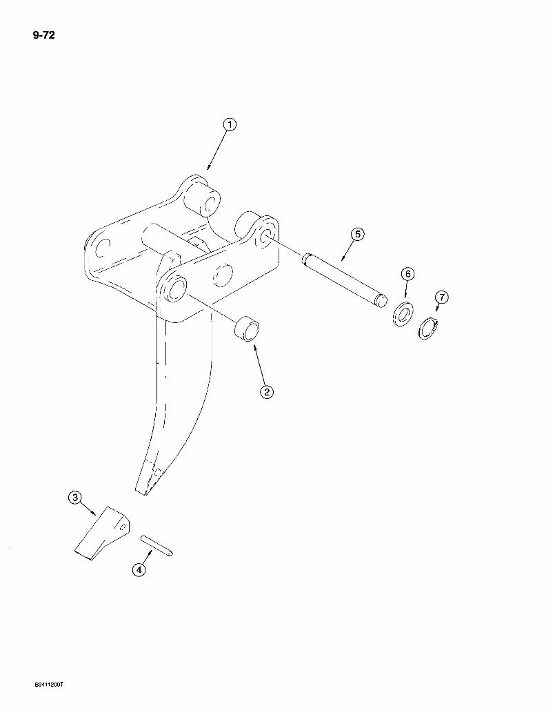
9-72
B9411200T
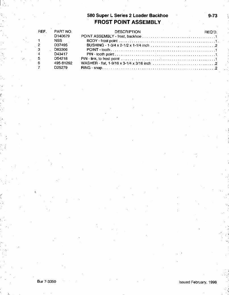
580 Super L Series 2 Loader Backhoe 9-73 FROST POINT ASSEMBLY
REF. P A R T NO. D E S C R I P T I O N R E Q ' D . D140679 POINT A S S E M B L Y - frost, backhoe . ; 1
1 N S S B O D Y - frost point 1 2 D37495 B U S H I N G - 1-3/4 X 2-1/2 X 1-1/4 inch .2 3 D83306 POINT - tooth 1 4 D43417 P I N - t o o t h point 1 5 D54218 PIN - link, to frost point 1 6 495 -81292 W A S H E R - f lat, 1-9/16 x 3-1/4 x 3/16 inch 2 7 D25279 RING - snap 2
Bur 7-3350 Issued February, 1998
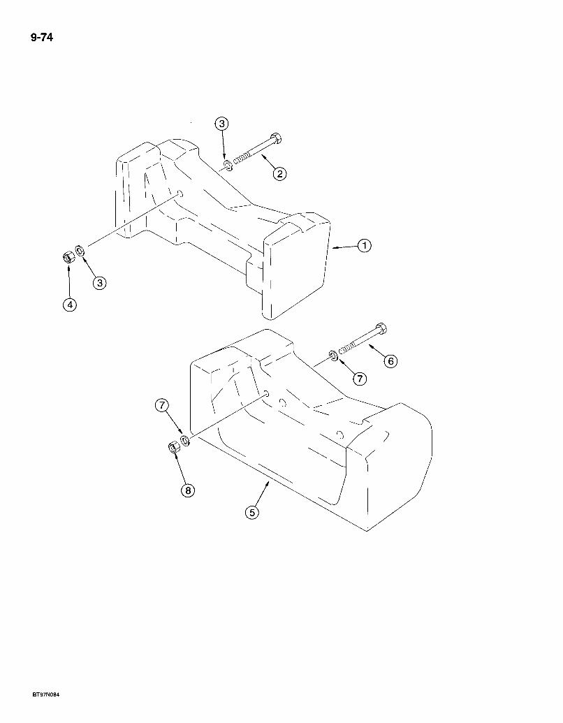
9-74
580 Super L Series 2 Loader Backhoe FRONT COUNTERWEIGHT
9-75
REF. P A R T NO. 1 194520A1 2 827 -20170 3 896 -11020 4 829-1420
5 230513A1 6 827 -20170 7 896 -11020 8 829-1420
D E S C R I P T I O N R E Q ' D . C O U N T E R W E I G H T - front, 2 0 0 kg (441 lbs), if used -1 B O L T - hex, 2 0 - 2.5 x 170 m m , c lass 10.9 .2 W A S H E R - flat, 22 x 37 x 4 m m , hardened 4 N U T - hex, 20 m m - 2.5, c lass 10 2
C O U N T E R W E I G H T - f ront, 408 kg (900 lbs), if used 1 B O L T - hex, 2 0 - 2.5 x 170 m m , c lass 10.9 2 W A S H E R - f l a t , 2 2 x 3 7 x 4 m m , hardened 4 N U T - hex, 2 0 m m - 2.5, c lass 10 2
Bur 7-3350 Issued February, 1998

9-76
2 0 ) \ _
( 2 2 )
REF.
580 Super L Series 2 Loader Backhoe CHASSIS AND OPERATOR COMPARTMENT POD MOUNTS
P A R T NO. D E S C R I P T I O N
CHASSIS
9-77
R E Q ' D .
1 2 3 4 5 6 7 8 8A 9
10 11 12 13 14 15 16 17 18 19 20 21 22 23 24 25 26
299395A1 180427A1 D127542 192559A1 D151069 0 1 5 1 0 7 0 220413A1 107124A1 185356A1 219-55
827-16110 495 -81259 D138565 186977A1 829 -1416 141249A1 627 -12030 896 -11012 827 -16110 495 -81259 186977A1 D138565 829-1416 180578A1 A14145.1 186977A1 829-1416
C H A S S I S - loader backhoe , integral 1 B U S H I N G - loader f rame pivot -2 B U S H I N G - f ront ax le pivot 2 B U S H I N G - 80 m m ID, swing cyl inder p i v o t . . 2 B U S H I N G - 70 mn i ID, upper, backhoe f rame, sw ing tower mount ing 1 B U S H I N G - 7 0 m m ID, lower, backhoe f rame, sw ing tower moun t ing 1 S P A C E R - 93 X 135 X 5 m m , bear ing, we lds to f rame 1 B U S H I N G - lower, s ide, backhoe f rame, at stabi l izer leg mount ing .4 B O S S - 1 0 m m , we lded to chass is f rame 7
F ITTING - g rease , 90 degree , 1/8 PT x 27/32 inch, loader f rame pivot. 2
OPERATOR COMPARTMENT POD MOUNTS
B O L T - hex, 16 - 2^0 x 110 m m , c lass 10.9 1 W A S H E R - flat, 21 /32 x 2 x 1/4 inch . 1 I N S U L A T O R - mount ing , f rame, upper, f i rewal l 2 W A S H E R - f l a t , special 1 N U T - h e x , 16 m m - 2 . 0 , c lass 10 1 B R A C K E T - mount ing , f rame, r ight-hand and lef t -hand .2 B O L T - hex, ful l th reads , 12 - 1.75 x 3 0 m m , c lass 10.9 4 W A S H E R - f lat, 13.5 x 24 x 3 m m , hardened 4 B O L T - hex, 16 - 2.0 x 110 m m , c lass 10.9 .2 W A S H E R - f lat, 21 /32 x 2 x 1/4 inch 2 W A S H E R - f lat, specia l 4 I N S U L A T O R - mount ing , f rame, lower, f ront 4 . N U T - hex, 16 m m - 2 . 0 , c lass 10 2 B O L T - s p e c i a l 2 M O U N T - rubber, f rame, rear 2 W A S H E R - flat, specia l 2 N U T - h e x , 16 m m - 2 . 0 , c lass 10 2
Bur 7-3350 Issued February, 1998
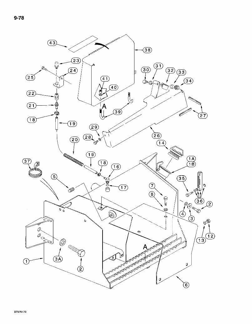
9-78
3 2 ) ( 3 3 )
S2.

580 Super L Series 2 Loader Backhoe BATTERY BOX, HYDRAULIC OIL TANK AND
RIGHT-HAND STEP
9-79
REF. PART NO. 1 283325A3 1A 230857A1 IB 440-1066 2 627-20040 3 302358A1 3A 896-11020 4 185926A1 5 217-436 6 231656A1 7 614-10025 8 495-21044 12 218-5211 13 237-6010 14 138595A1 16 217-347 17 237-6006 18 214-1406 19 143218A1 20 143219A1 21 217-380 22 217-1102 23 120943A1 24 122603A1 25 , 121856A1 26 188008A2
27 *191047A1 28 614-8016 29 895-15008 30 814-10045 31 892-11010 32 D138055 33 120303A1 34 829-1410
DESCRIPTION REQ'D. TANK - hydraulic oil, right-hand side of chassis 1
SCREEN - strainer, fill tube 1 SCREW - machine, pan Phillips, No. 6 NC x 3/8 inch . 2
BOLT - hex, full threads, 20 - 2.5 x 40 mm, class 10.9 4 WASHER - flat, hardened, special, right-hand side of tank. 2 WASHER - fiat, 22 x 37 x 4 mm, hardened, left-hand side of tank 2 SPACER - bushing, right-hand side of tank 2 PLUG - hex socket headless, 3/8 inch PT, if used COVER - battery, 3 mm thick BOLT - hex, full threads, 10 -1.5 x 25 mm WASHER-flat, 7/16x1 x 5/64 inch PLUG - hex socket, 7/8-14 inch 0-ring boss, drain
0-RING - 3/4 ID X 3/32 inch wide CAP - hydraulic oil tank, nonvented ELBOW - 90 degree, 3/8 stem end x 9/16-18 inch adj 0-ring boss.
0-RING -15/32 ID x 5/64 inch wide CLAMP - adj, 7/16 - 25/32 inch dia HOSE - 9.5 (3/8) x 15 (19/32) x 735 mm (28-15/16 inch) long, vent GUARD - hose sleeve ADAPTER - straight, 3/8 inch stem end x PT . COUPLING - pipe, 3/8 inch . BREATHER - pressure vacuum, hydraulic oil tank BRACKET - breather mounting BOLT - hex washer, special, 10 -1.5 x 30 mm COVER - right-hand loader lift frame tubing, mounted above hydraulic oil tank TRIM - edge, 315 mm (12-13/32 inch) long BOLT - hex, full threads, 8 -1.25 x 16 mm WASHER - flat, 9 x 20 x 1.6 mm BOLT - hex, 10 - 1.5 x 45 mm WASHER - lock, 10 mm CLAMP-tube SPACER - clamp. NUT - hex, 10 mm -1.5, class 10.9
*NdTE: Apply 75 mm (3 inch) of trim to front lower edge and 240 mm (9-7/16 inch) of trim to outside lower edge of cover.
Continued on next page
Bur 7.3350 Issued February, 1998
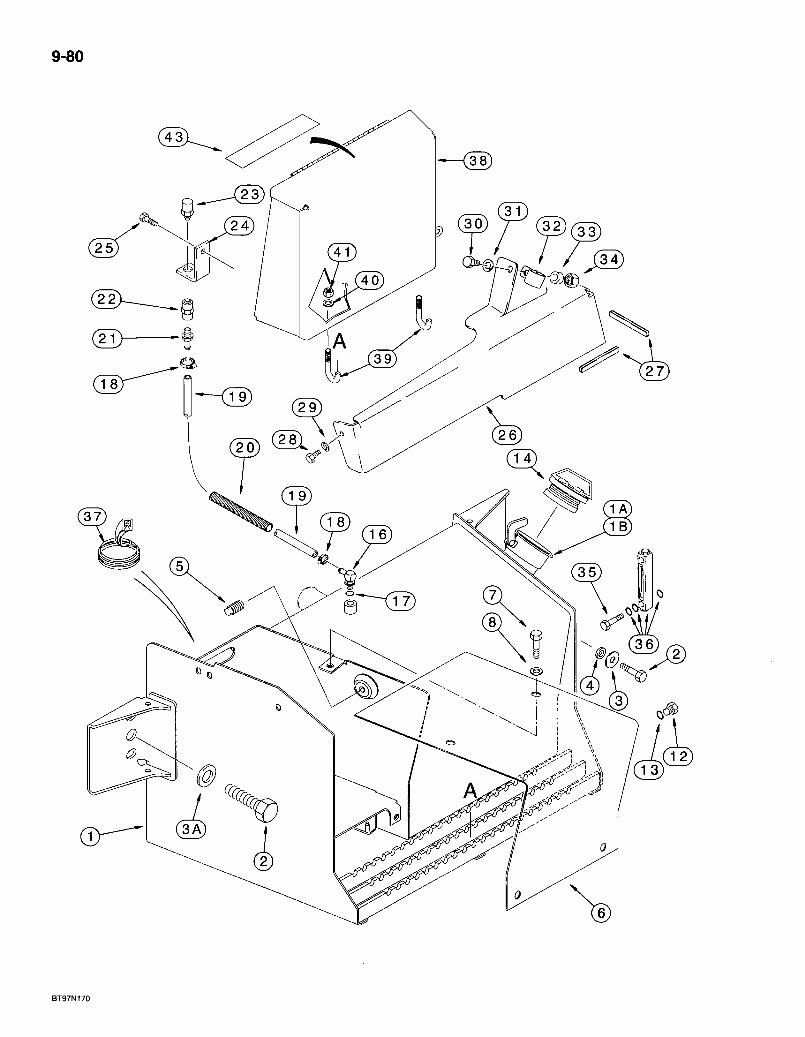
9-80
BT97N170
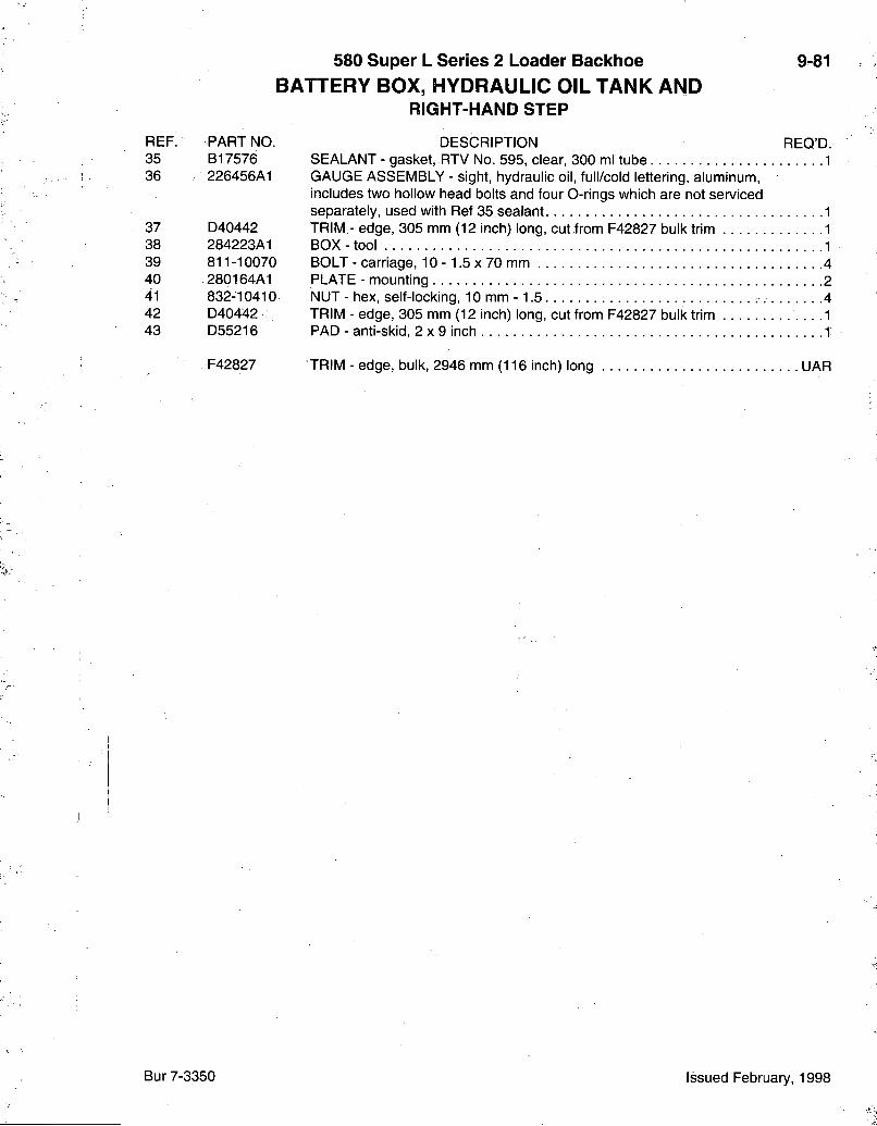
580 Super L Series 2 Loader Backhoe BATTERY BOX, HYDRAULIC OIL TANK AND
RIGHT-HAND STEP
9-81
REF. 35 36
37 38 39 40 41 42 43
PART NO. B17576 226456A1
D40442 284223A1 811-10070 280164A1 832-10410 D40442 D55216
F42827
DESCRIPTION REQ'D. SEALANT - gasket, RTV No. 595, clear, 300 ml tube 1 GAUGE ASSEMBLY - sight, hydraulic oil, full/cold lettering, aluminum, includes two hollow head bolts and four O-rings which are not serviced separately, used with Ref 35 sealant 1 TRIM - edge, 305 mm (12 inch) long, cut from F42827 bulk trim 1 BOX-tool 1 BOLT - carriage, 10 - 1.5 x 70 mm 4 PLATE - mounting 2 NUT - hex, self-locking, 10 mm -1.5 4 TRIM - edge, 305 mm (12 inch) long, cut from F42827 bulk trim .1 PAD - anti-skid, 2 x 9 inch 1
TRIM - edge, bulk, 2946 mm (116 inch) long UAR
Bur 7-3350 Issued February, 1998
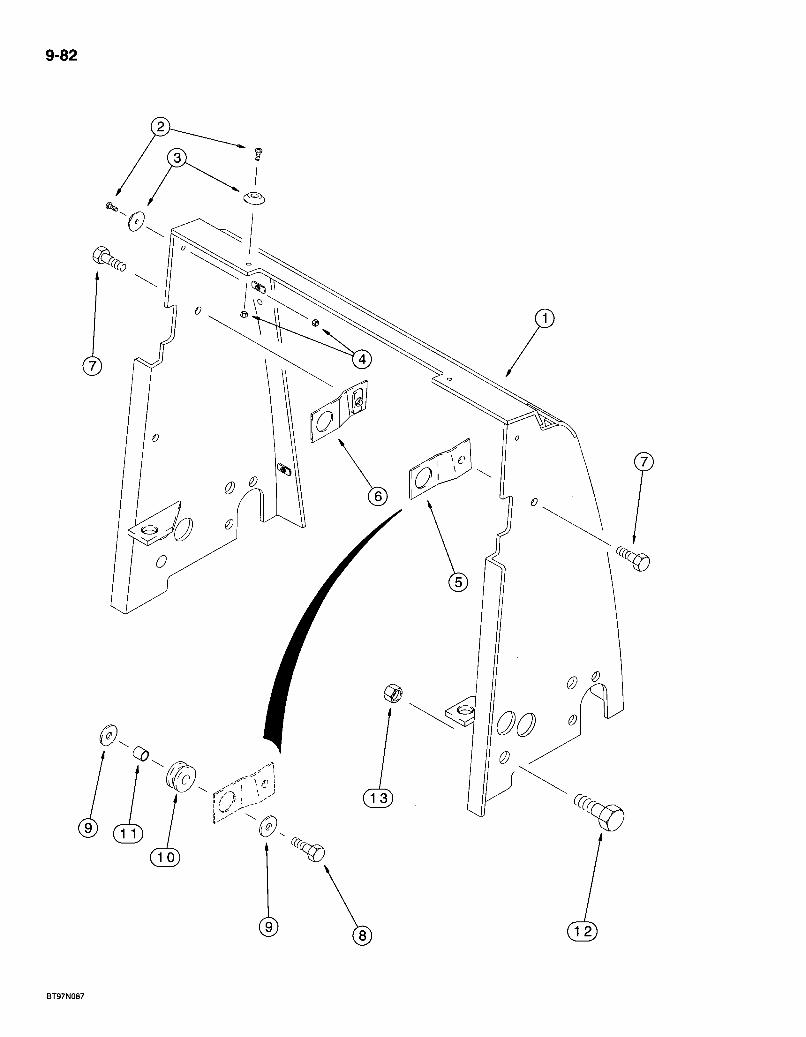
9-82
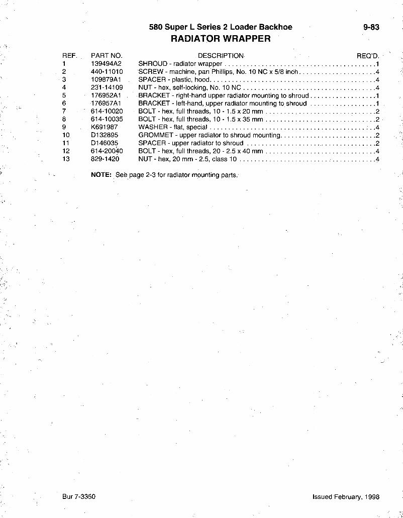
580 Super L Series 2 Loader Backhoe RADIATOR WRAPPER
9-83
REF. PART NO. DESCRIPTION REQ'D. 1 139494A2 SHROUD - radiator wrapper 1 2 440-11010 SCREW-machine, pan Phillips, No. 10 NC X 5/8 inch 4 3 109879A1 SPACER - plastic, hood 4 4 231-14109 NUT - hex, self-locking, No. 10 NC 4 5 176952A1 BRACKET - right-hand upper radiator mounting to shroud 1 6 176957A1 BRACKET - left-hand, upper radiator mounting to shroud 1 7 614-10020 BOLT -hex, full threads, 10-1 .5x20 mm 2 8 614-10035 BOLT - hex, full threads, 10 - 1.5 x 35 mm 2 9 K691987 WASHER - flat, special • .4 10 D132895 GROMMET - upper radiator to shroud mounting 2 11 D146035 SPACER - upper radiator to shroud 2 12 614-20040 BOLT-hex, full threads, 20-2 .5x40 mm 4 13 829-1420 NUT - hex, 20 mm - 2.5, class 10 4
NOTE: See page 2-3 for radiator mounting parts.
Bur 7-3350 Issued February, 1998

9-84
« r ^ I 1/ .5>
/ ^ ^ ^ ^
//
^1)
BT97N088

580 Super L Series 2 Loader Backhoe 9-85 PUMP GUARD
REF. PART NO. DESCRIPTION REQ'D. 1 229676A1 GUARD - pump, plate 1 2 121856A1 BOLT-hex washer, special, 10 -1.5 X 30 mm 2
Bur 7-3350 Issued February, 1998
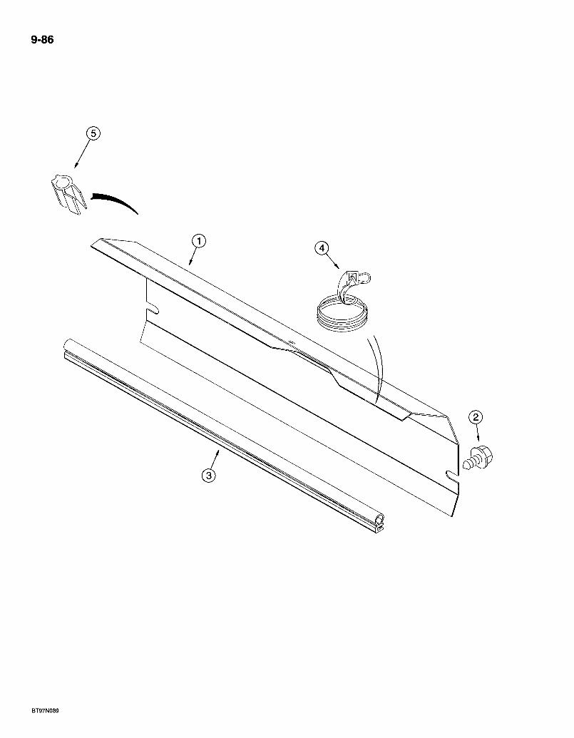
9-86
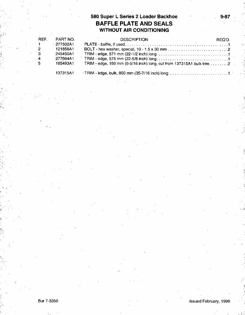
580 Super L Series 2 Loader Backhoe 9-87 B A F F L E PLATE AND S E A L S
WITHOUT AIR CONDITIONING
REF. PART NO. DESCRIPTION REQ'D. 1 277502A1 PLATE - baffle, if used 1 2 121856A1 BOLT - hex washer, special, 10 -1.5 x 30 mm 2 3 245450A1 TRIM - edge, 571 mm (22-1/2 inch) long . . . . . . .1 4 277664A1 TRIM - edge, 575 mm (22-5/8 inch) long 1 5 185493A1 TRIM - edge, 160 mm (6-5/16 inch) long, cut from 137315A1 bulk trim 2
137315A1 TRIM - edge, bulk, 900 mm (35-7/16 inch) long 1
Bur 7-3350 Issued February, 1998

9-88
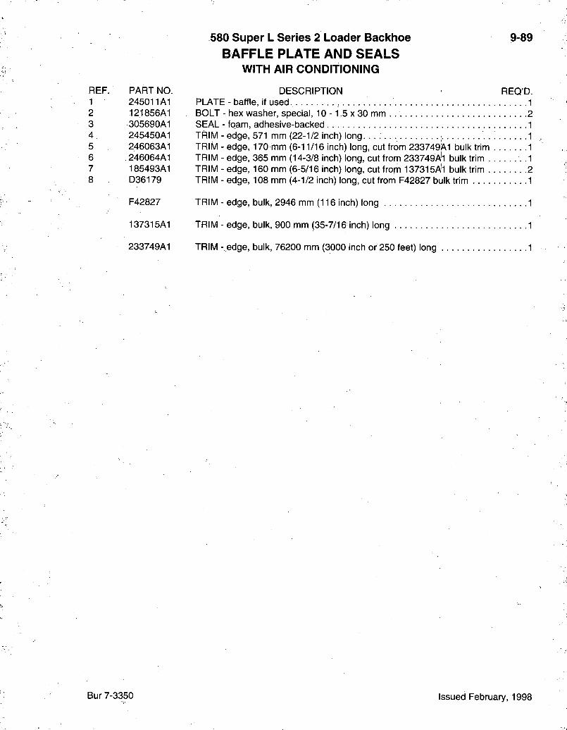
REF. PART NO 1 245011A1 2 121856A1 3 305690A1 4 245450A1 5 246063A1 6 246064A1 7 185493A1 8 D36179
F42827
137315A1
233749A1
580 Super L Series 2 Loader Backiioe B A F F L E PLATE AND S E A L S
WITH AIR CONDITIONING
9-89
DESCRIPTION REQ'D. PLATE - baffle, if used 1 BOLT - hex washer, special, 10 -1.5 x 30 mm 2 SEAL - foam, adhesive-backed 1 TRIM - edge, 571 mm (22-1/2 inch) long. 1 TRIM - edge, 170 mm (6-11/16 inch) long, cut from 233749A1 bulk trim 1 TRIM - edge, 365 mm (14-3/8 inch) long, cut from 233749AH bulk trim .1 TRIM - edge, 160 mm (6-5/16 inch) long, cut from 137315Al bulk trim 2 TRIM - edge, 108 mm (4-1/2 inch) long, cut from F42827 bulk trim 1
TRIM - edge, bulk, 2946 mm (116 inch) long 1
TRIM - edge, bulk, 900 mm (35-7/16 inch) long 1
TRIM - edge, bulk, 76200 mm (3000 inch or 250 feet) long 1
Bur 7-3350 Issued February, 1998
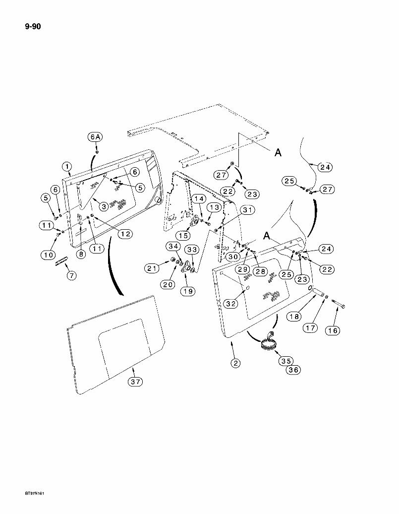
9-90
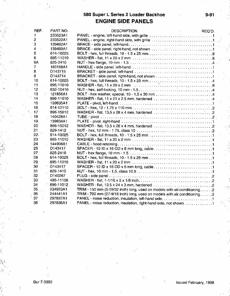
580 Super L Series 2 Loader Bacl<lioe ENGINE SIDE PANELS
9-91
REF. PART NO. 1 233523A1 2 233522A1 3 139492A1 4 139490A1 5 614^10025 6 895-11010 6A 825-2410 7 183168A1 8 D143715 9 D143714 10 614-10025 11 895-11010 12 832-10410 13 121856A1 14 896-11010 15 139835AT 16 814-12110 17 896-15012
- 18 140428A1 19 139834A1 20 896-15012 21 829-1412 22. 614-10025 23 895-11010 24 144908A1 25 D143417 27 825-2410 28 614-10025 29 895-11010 30 D143417 31 829-1410 32 D140267 33 495-11106 34 896-11012 35 234923A1 36 244441A1 37 297837A1 38 297836A1
DESCRIPTION REQ'D. PANEL - engine, left-hand side, with grille 1 PANEL - engine, right-hand side, with grille . 1 BRACE - side panel, left-hand -1 BRACE - side panel, right-hand, not shown 1 BOLT - hex, full threads, 10 -1.5 x 25 mm 8 WASHER-flat, 11 x 20 x2 mm 8 NUT - hex flange, 10 mm - 1.5 4 HANDLE - side panel, left-hand 1 BRACKET - side panel, left-hand .1 BRACKET - side panel, right-hand, not shown I. . . ; 1 BOLT-hex, full threads, 10- 1.5x25 mm : . .4 WASHER - flat, 11 x 20 x 2 mm 8 NUT - hex, self-locking, 10 mm -1.5 4 BOLT - hex washer, special, 10 -1.5 x 30 mm 4 WASHER - flat, 11x21x2.5 mm, hardened 4 PLATE-pivot, left-hand 1 BOLT - hex, 12 - 1.75 x 110 mm .2 WASHER - flat, 13.5 x 28 x 4 mm, hardened .2 TUBE-pivot 2 PLATE - pivot, right-hand 1 WASHER - flat, 13.5 x 28 x 4 mm, hardened 2 NUT - hex, 12 mm -1.75, class 10 2 BOLT - hex, full threads, 10 -1.5 x 25 mm 1 WASHER - flat, 11 x 20 x 2 mm . 1 CABLE - hood retaining 1 SPACER -10 ID x 16 OD X 6 mm long, cable. .1 NUT - hex flange, 10 mm -1.5 1 BOLT - hex, full threads, 10 -1.5 x 25 mm 1 WASHER-flat, 11 x 20x2 mm 1 SPACER -10 ID x 16 OD X 6 mm long, cable 1 NUT - hex, 10 mm -1.5, class 10.9 1 PLUG -side panel. 2 WASHER - flat, 1-1/16 x 2 x 1/8 inch .2 WASHER - flat, 13.5 x 24 x 3 mm, hardened 2 TRIM -150 mm (5-29/32 inch) long, used on models with air conditioning 2 TRIM - 700 mm (27-9/16 inch) long, used on models with air conditioning 2 PANEL - noise reduction, insulation, left-hand side. 1 PANEL - noise reduction, insulation, right-hand side, not shown 1
Bur 7-3350 Issued February, 1998

9-92
BT97N169
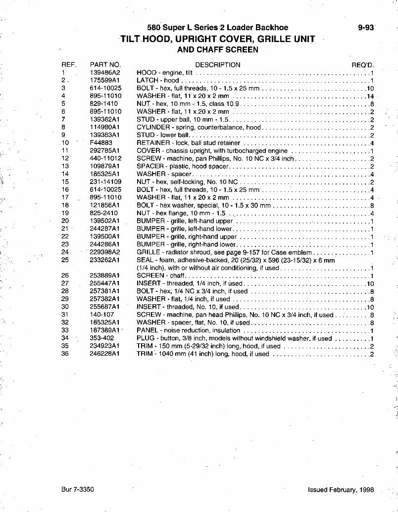
580 Super L Series 2 Loader Backiioe TILT HOOD, UPRIGHT COVER, GRILLE UNIT
AND CHAFF SCREEN
9-93
REF. PART NO. 1 139486A2 2 , 175599A1 3 614-10025 4 895-11010 5 829-1410 6 895-11010 7 139362A1 8 114980A1 9 139363A1 10 F44883 11 292785A1 12 440-11012 13 109879A1 14 185325A1 15 231-.14109 16 614-10025 17 895-11010 18 121856A1 19 825-2410 20 139502A1 21 .244287A1 22 139500A1 23 244286A1 24 229398A2 25 233262A1
26 253889A1 27 255447A1 28 257381A1 29 257382A1 30 255687A1 31 140-107 32 185325A1 33 187389A1 34 353-402 35 234923A1 36 246228A1
DESCRIPTION REQ'D. HOOD - engine, tilt 1 LATCH-hood 1 BOLT - hex, full threads, 10 -1.5 x 25 mm 10 WASHER - flat, 11 X 20 X 2 mm . 1 4 NUT - hex, 10 mm -1.5, class 10.9 8 WASHER - flat, 11 x 20 x 2 mm 2 STUD- upper ball, 10 mm-1.5 -2 CYLINDER - spring, counterbalance, hood 2 STUD-lower ball. 2 RETAINER - lock, ball stud retainer 4 COVER - chassis upright, with turbocharged engine 1 SCREW - machine, pan Phillips, No. 10 NC x 3/4 inch .2 SPACER - plastic, hood spacer 2 WASHER - spacer 4 NUT - hex, self-locking. No. 10 NC 2 BOLT-hex, full threads, 10- 1.5x25 mm .4 WASHER - flat, 11 x 20 x 2 mm 4 BQLT- hex washer, special, 10 -1.5 x 30 mm .8 NUT-hex flange, 10mm- i . 5 . 4 BUMPER - grille, left-hand upper 1 BUMPER - grille, left-hand lower. 1 BUMPER - grille, right-hand upper 1 BUMPER - grille, right-hand lower 1 GRILLE - radiator shroud, see page 9-157 for Case emblem 1 SEAL - foam, adhesive-backed, 20 (25/32) x 596 (23-15/32) x 6 mm (1/4 inch), with or without air conditioning, if used 1 SCREEN-chaff 1 INSERT - threaded, 1/4 inch, if used . 10 BOLT - hex, 1/4 NC x 3/4 inch, if used 8 WASHER - flat, 1/4 inch, if used 8 INSERT - threaded, No. 10, if used 10 SCREW - machine, pan head Phillips, No. 10 NC x 3/4 inch, if used 8 WASHER - spacer, flat, No. 10, if used 8 PANEL - noise reduction, insulation 1 PLUG - button, 3/8 inch, models without windshield washer, if used 1 TRIM -150 mm (5-29/32 inch) long,.hdod, if used 2 TRIM - 1040 mm (41 inch) long, hood, if used 2
Bur 7-3350 Issued February, 1998
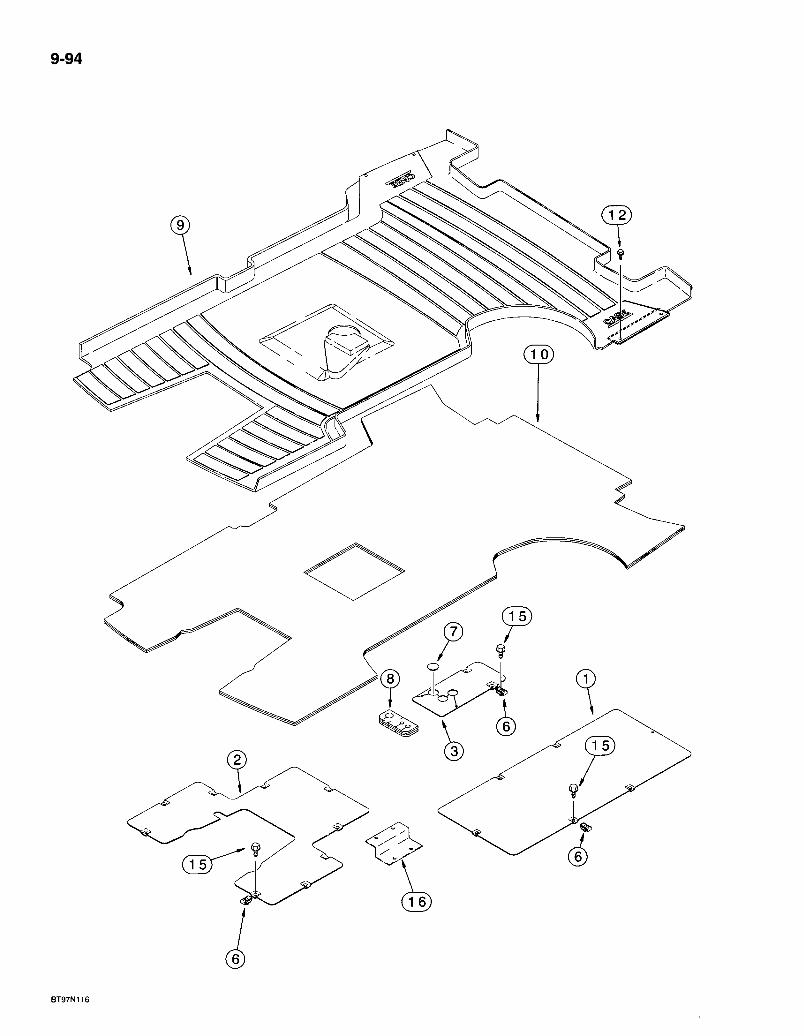
9-94
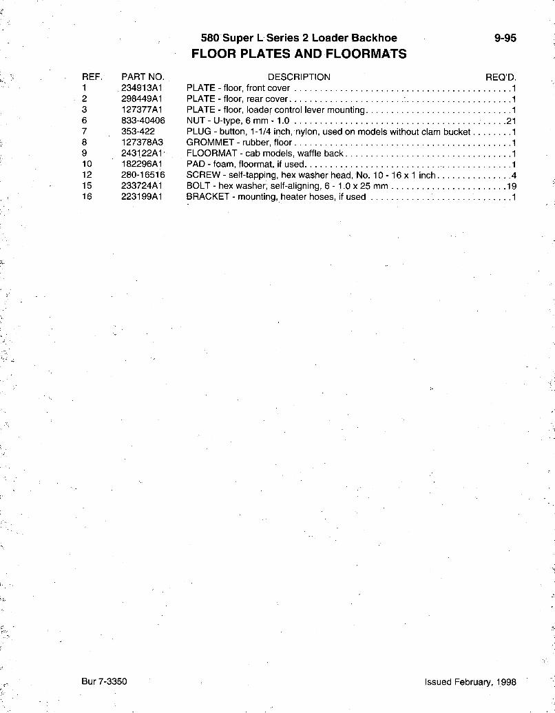
580 Super L Series 2 Loader Backhoe FLOOR PLATES AND FLOORMATS
9-95
REF. PART NO. 1 234913A1 2 298449A1 3 127377A1 6 833-40406 7 353-422 8 127378A3 9 243122A1 10 182296A1 12 280-16516 15 233724A1 16 223199A1
DESCRIPTION REQ'D. PLATE - floor, front cover PLATE - floor, rear cover PLATE - floor, loader control lever mounting NUT - U-type, 6 mm -1.0 PLUG - button, 1-1/4 inch, nylon, used on models without clam bucket GROMMET - rubber, floor FLOORMAT - cab models, waffle back PAD - foam, floormat, if used. SCREW - self-tapping, hex washer head, No. 1 0 - 1 6 x 1 inch 4 BOLT - hex washer, self-aligning, 6 - 1.0 x 25 mm 19 BRACKET - mounting, heater hoses, if used 1
Bur 7-3350 Issued February, 1998
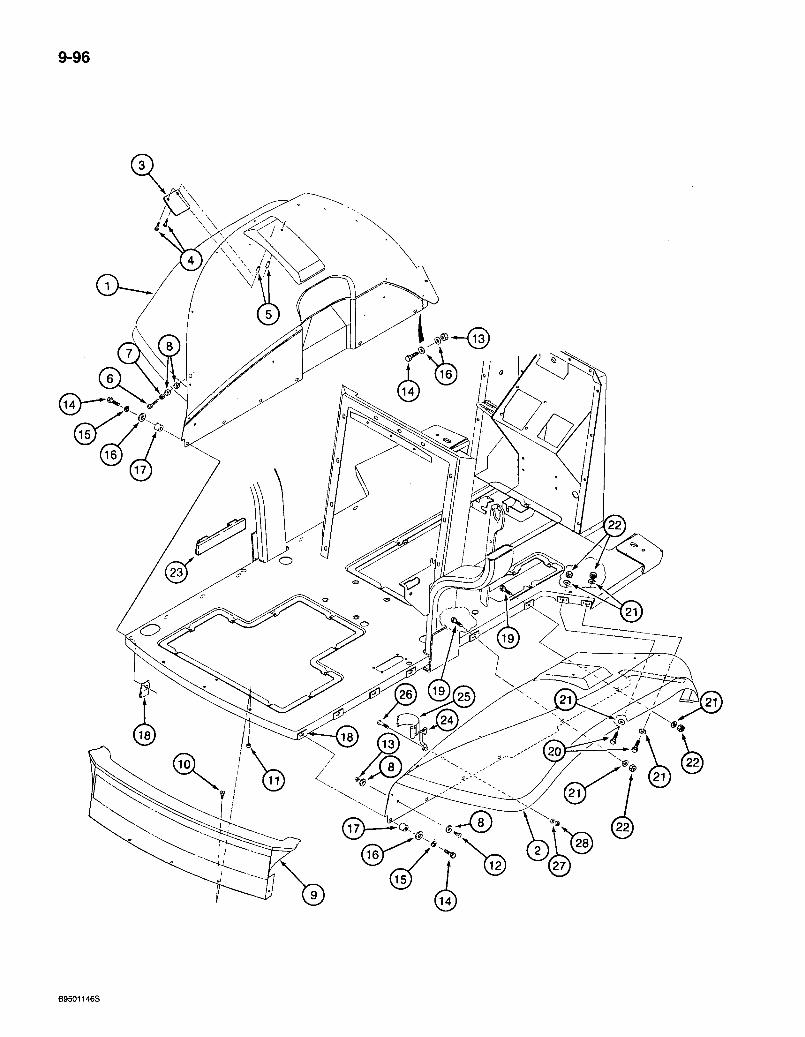
9-96
B9501146S

580 Super L Series 2 Loader Backhoe REAR FENDERS AND REAR CLOSURE PANEL
ROPS CANOPY MODELS
9-97
REF. PART NO. 1 133025A1 2 133024A1 3 141404A1 4 781-24830 5 144282A1 6 413-516 7 . 492-11031 8 495-21038 9 136745A1 10 112865A1 11 425-285 12 614-8025 13 . 832-10408 14 614-8030 15 . 892-11008 16 495-81001 17 144282A1 18 833-40408 19 614-8045
20 .814-8035
21 895r11008 22 832^10408 23 188482A1 24 182594A1 25 184726A1 26 842-1425 27 895-11004 28 832-10404
DESCRIPTION REQ'D. FENDER-left-hand. 1 FENDER - right-hand • • • -1 PLATE - fender support 2 BOLT - hex flange, self-tapping, 8 - 1.25 x 30 mm 4 SPACER -16 X 10 mm long, fender support plate 4 BOLT - hex, 5/16 NC x 1 inch . . 2 WASHER-lock, 5/16 inch 2 WASHER - flat, 3/8x 7/8 x 3/32 inch. 8 PANEL - rear closure. 1 SCREW - pointed, self-aligning, special, 5/16 NC x 13/16 inch 3 NUT - hex flange, 5/16 inch NC. : 3 BOLT - hex, full threads, 8 - 1,25 x 25 mm 2 NUT - hex, self-locking, 8 mm - 1.25 4 BOLT - hex, full threads, 8 - 1.25 x 30 mm 12 WASHER - lock, 8 mm 19 WASHER - flat, 3/8 x 1-1/8 x 1/16 inch-. 14 SPACER - 16 X 10 mm long .10 NUT-U-type, 8mm-1.25 .12 BOLT - hex, full threads, 8 - 1.25 x 45 rnm, mud guard to fender, see page 9-101 for mud guard . 2 BOLT - hex, 8 -1.25 x 35 mm, mud guard to fender, see page 9-101 for mud guard 2 WASHER - flat, 9 x 17 x 1.6 mm 6 NUT - hex, self-locking, 8 mm - 1.25 4 SEAL - foam, fender - 2 BRACKET - velcro retainer 2 STRAP - velcro, right-hand fender 1 SCREW - machine, oval countersunk Phillips, 4 - 0.7 x 25 mm .4 WASHER - flat, 4.4:X 9 x 0.8 mm 4 NUT - hex, self-locking, 4 mm - 0 .7 . . . 4
Bur 7-3350 issued February, 1998
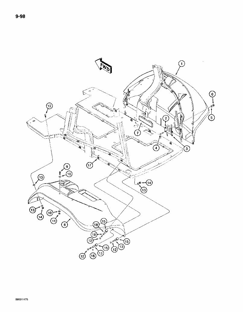
9-98
B9501147S
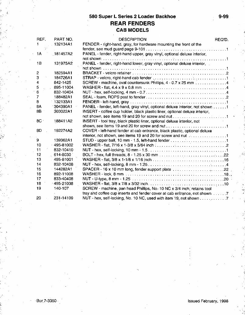
580 Super L Series 2 Loader Backhoe REAR FENDERS
CAB MODELS
9-99
REF. PART NO. 1 132134A1
1A 181457A2
1B 131975A2
2 182594A1 3 184726A1 4 842-1425 5 , 895-11004 6 832-10404 7 188482A1 8 132133A1 8A 304390A1 SB 303022A1
8C 188411A2
8D 192274A2
9 139362A1 10 495-81002 11 832-10410 12 . 614-8030 13 495-81001 14 832-10408 15 144282A1 16 892-11008 17 833-40408 18 495-21038 19 140-107
20 231-14109
DESCRIPTION REQ'D. FENDER - right-hand, gray, for hardware mounting the front of the fender, see mud guard page 9-101 1 PANEL - fender, right-hand upper, gray yinyl, optional deluxe interior, not shown ; 1 PANEL - fender, right-hand lower, gray vinyl, optional deluxe interior, not shown 1 BRACKET - velcro retainer 2 STRAP - velcro, right-hand cab fender 1 SCREW - machine, oval countersunk Phillips, 4 - 0.7 x 25 mm 4 WASHER - flat, 4.4 x 9 x 0.8 mm 4 NUT - hex, self-locking, 4 mm - 0.7 4 SEAL - foam, ROPS post to fender 2 FENDER - left-hand, gray 1 PANEL - fender, left-hand, gray vinyl, optional deluxe interior, not shown 1 INSERT - coffee cup holder, black plastic liner, optional deluxe interior, not shown, see items 19 and 20 for screw and nut .1 INSERT - tool tray, black plastic liner, optional deluxe interior, not shown, see items 19 and 20 for screw and n u t . . . . . . 1 COVER - left-hand fender at cab entrance, black plastic, optional deluxe interior,, not shown, see items 19 and 20 for screw and nut 1 STUD - upper ball, 10 mm -1.5, left-hand fender 1 WASHER - flat, 7/16x1 -3/8 x 5/64 inch .2 NUT - hex, self-locking, 10 mm -1.5 1 BOLT - hex, full threads, 8 - 1.25 x 30 mm .22 WASHER - flat, 3/8 x 1-1/8 x 1/16 inch 16 NUT - hex, self-locking, 8 mm -1 ;25 4 SPACER -16 X 10 mm long, fender support plate , 22 WASHER - lock, 8 mm 18 NUT - U-type, 8 mm -1.25 20 WASHER - flat, 3/8 x 7/8 x 3/32 inch 10 SCREW - machine, pan head Phillips, No.-10 NC x 3/4 inch, retains tool tray and coffee cup inserts and fender cover at cab entrance, not shown 7 NUT - hex, self-locking. No. 10 NC, used with item 19, not shown 7
Bur. 7-3350 Issued February, 1998
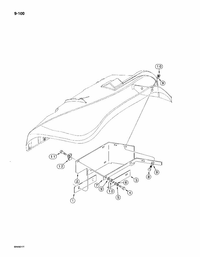
9-100
^^^^^ h--—-n^-^ V
3h i---
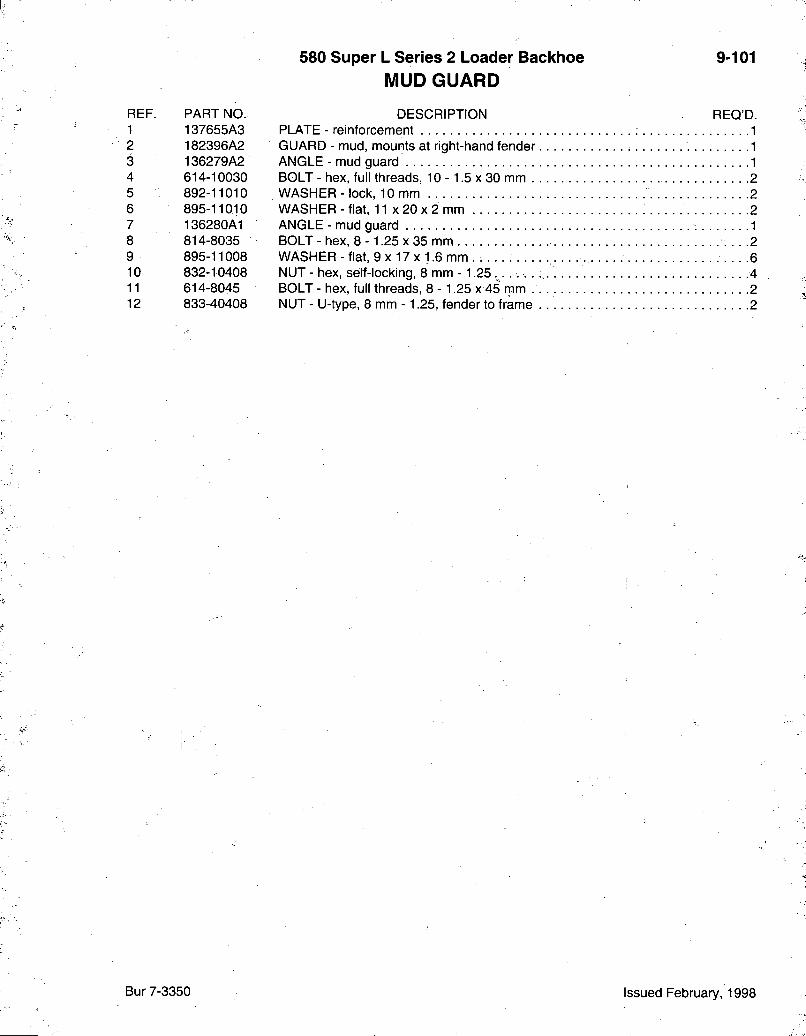
580 Super L Series 2 Loader Backhoe MUD GUARD
9-101
REF. PART NO. 1 137655A3 2 182396A2 3 136279A2 4 614-10030 5 892-11010 6 895-11010 7 136280A1 8 814-8035 9 895-11008 10 832-10408 11 614-8045 12 833-40408
DESCRIPTION REQ'D. PLATE - reinforcement 1 GUARD - mud, mounts at right-hand fender 1 ANGLE - mud guard 1 BOLT - hex, full threads, 10 -1.5 x 30 mm .2 WASHER - lock, 10 mm 2 WASHER - flat, 11 x 20 x 2 mm 2 ANGLE - mud guard 1 BOLT - hex, 8 - 1.25 x 35 mm • • • -2 WASHER - flat, 9 x 17 x 1.6 mm . . . . . -6 NUT - hex, self-locking, 8 mm -1.25 4 BOLT - hex, full threads, 8 - 1.25 x 45 rpm . . . . 2 NUT - U-type, 8 mm - 1.25, fender to frame 2
Bur 7-3350 Issued February, 1998
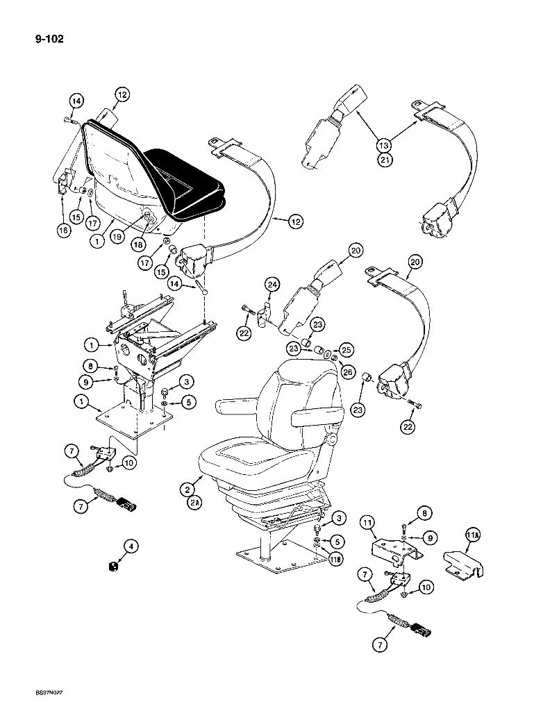
9-102
BS97N022
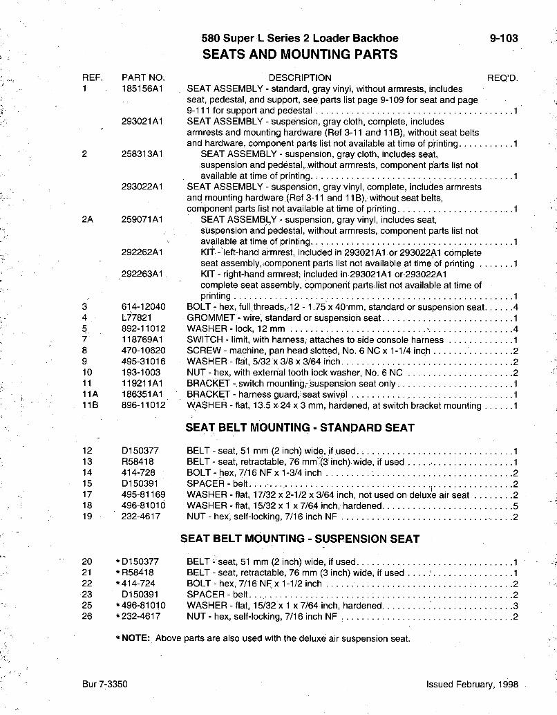
580 Super L Series 2 Loader Baclchoe SEATS AND MOUNTING PARTS
9-103
REF. PART NO. DESCRIPTION REQ'D. 1 185156A1 SEAT ASSEMBLY - standard, gray vinyl, without armrests, includes
seat, pedestal, and support, see parts list page 9-109 for seat and page 9-111 for support and pedestal 1
293021A1 SEAT ASSEMBLY - suspension, gray cloth, complete, includes armrests and mounting hardware (Ref 3-11 and 11 B), without seat belts and hardware, component parts list not available at time of printing 1
2 258313A1 SEAT ASSEMBLY - suspension, gray cloth, includes seat, suspension and pedestal, without armrests, component parts list not available at time of printing.; 1
293022A1 SEAT ASSEMBLY - suspension, gray vinyl, complete, includes armrests and mounting hardware (Ref 3-11 and 11B), without seat belts, component parts list not available at time of printing 1
2A 259071A1 SEAT ASSEMBLY - suspension, gray vinyl, includes seat, suspension and pedestal, without armrests, component parts list not available at time of printing 1
292262A1 KIT - left-hand armrest, included in 293021A1 or 293022A1 complete seat assembly,icomponent parts list not available at time of printing 1
292263A1 KIT - right-hand armrest; included in 293021A1 or 293022A1 complete seat assembly, component parts list not available at time of printing 1
3 614-12040 BOLT - hex, full,threads,,12 - 1.75 X 40*mm, standard or suspension seat 4 4 L77821 GROMMET -wire, standard or suspension seat 1 5. 892-11012 WASHER-lock, 12 mm 4 7 118769A1 SWITCH - limit, with harness, attaches to side console harness 1 8 470-10620 SCREW-machine, pan head slotted. No. 6 NCx 1-1/4 inch 2 9 495-31016 WASHER-flat, 5/32x3/8 X 3/64 inch. . . . . 2 10 193-1003 NUT - hex, with external tooth lock washer, No. 6 NC 2 11 119211A1 BRACKET-switch mounting,-suspension seat only. 1 11A 186351A1 BRACKET- harness guard, seat swivel 1 11B 896-11012 VVASHER - flat, 13.5 x 24x 3 mm, hardened, at switch bracket mounting 1
SEAT BELT MOUNTING - STANDARD SEAT
12 D150377 BELT - seat, 51 mm (2 inch) wide, if used. 1 13 R58418 BELT - seat, retractable, 76 mm^ (3 inch) wide, if used 1 14 414-728 BOLT-hex, 7/16 NFx 1-3/4 inch 2 15 D150391 SPACER - belt , 2 17 495-81169 WASHER - flat, 17/32 x 2-1/2 x 3/64 inch, not used on deluxe air seat 2 18 496-81010 WASHER - flat, 15/32 x 1 x 7/64 inch, hardened 5 19 232-4617 NUT - hex, self-locking, 7/16 inch NF 2
SEAT BELT MOUNTING- SUSPENSION SEAT
20 *D150377 BELT - seat, 51 mm (2 inch) wide, if used 1 21 * R58418 BELT - seat, retractable, 76 mm (3 inch) wide, if used 1 22 *414-724 BOLT - hex, 7/16 NF x 1-1/2 inch 2 23 D150391 SPACER - belt. . 2 25 * 496-81010 WASHER - flat, 15/32 x 1 x 7/64 inch, hardened 3 26 * 232-4617 NUT - hex, self-locking, 7/16 inch NF 2
* NOTE: Above parts are also used with the deluxe air suspension seat.
Bur 7-3350 Issued February, 1998
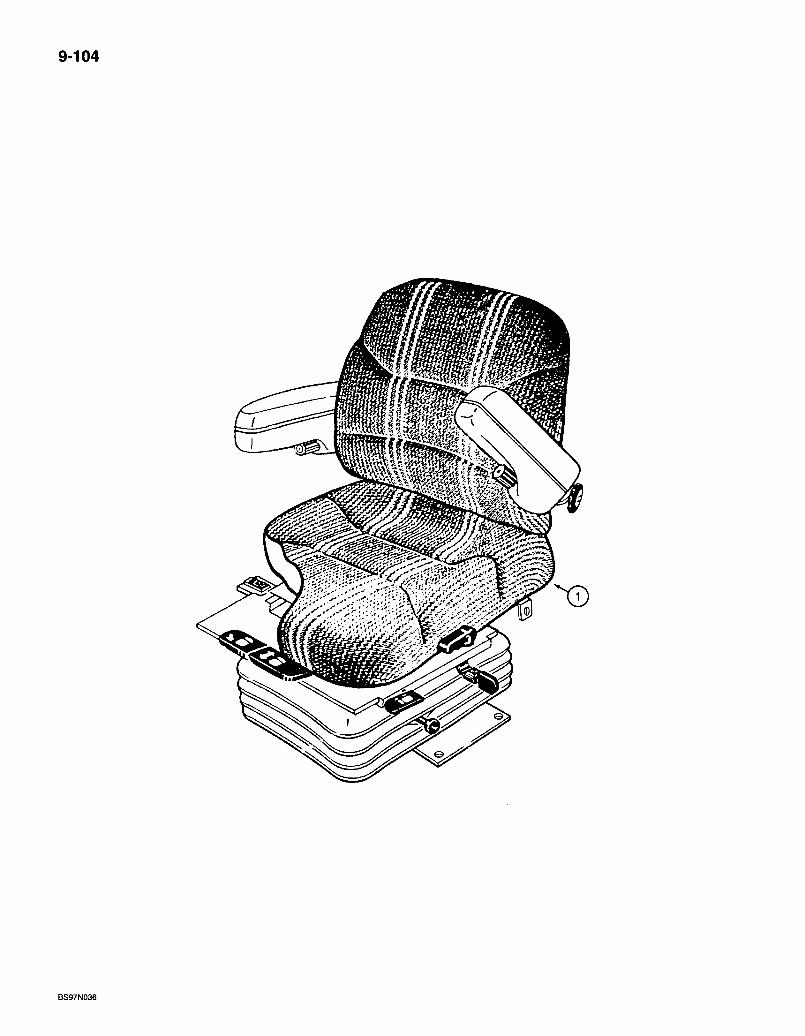
9-104
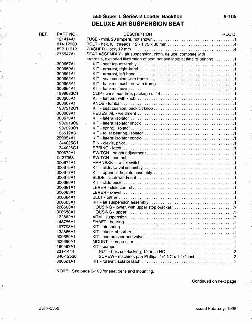
580 Super L Series 2 Loader Bacl<hoe DELUXE AIR SUSPENSION SEAT
9-105
REF. PART NO. DESCRIPTION REO'D. 121414A1 FUSE - mini, 20 ampere, not shown 1 614-12030 BOLT - hex, full threads, 12 - 1.75 x 30 mm 4 892-11012 WASHER - lock, 12 mm 4
1 275547A1 SEAT ASSEMBLY - air suspension, cloth, deluxe, complete with armrests, exploded illustration of seat not available at time of printing
300657A1 KIT - seat top assembly 300659A1 KIT - armrest, right-hand 300661A1 KIT - armrest, left-hand 300662A1 KIT - seat cushion, with frame 300663A1 KIT - backrest cushion, with frame 300664A1 KIT - backrest cover 1999693C1 CLIP - Christmas tree, package of 14 300665A1 KIT - lumbar, with knob 300667A1 KNOB - lumbar. 1987212C1 KIT - seat cushion, back tilt knob 300669A1 PEDESTAL - weldment 300670A1 KIT - lateral isolator 1987219C2 KIT - lateral isolator shock 1987290C1 KIT - spring, isolator 135512A3 KIT - roller bearing, isolator 259054A1 KIT - lateral isolator control 1344025C1 PIN - clevis, pivot 1344026C1 SPRING - latch 300672A1 SWITCH - height adjustment D137363 • SWITCH - contact 300674A1 HARNESS - swivel switch 300675A1 KIT - slide/swivel assembly 300677A1 KIT - upper slide plate assembly 300679A1 SLIDE - latch weldment 300680A1 KIT - slide puck 300681A1 LEVER - slide control 300683A1 LEVER-swivel 300684A1 BELT - tether 300685A1 KIT - air suspension assembly 226560A1 HOUSING - lower, with upper stop bracket 300688A1 HOUSING - upper 132862A1 ARM - suspension 143786A1 SHAFT - bearing 197793A1 KIT - air spring 132866A1 KIT - shock absorber 300689A1 KIT - compressor and valve 300690A1 MOUNT - compressor 180593A1 KIT-bumper 231-1444 NUT - hex, self-locking, 1/4 inch NC 2 340-12520 SCREW - machine, pan Phillips, 1/4 NC x 1-1/4 inch 2 300691A1 KIT - fore/aft isolator latch 1
NOTE: See page 9-103 for seat belts and mounting.
Continued on next page
Bur 7-3350 Issued February, 1998
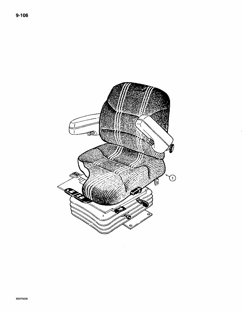
9-106
mm
BS97N036
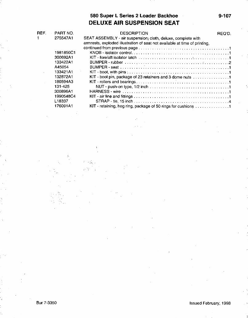
580 Super L Series 2 Loader Backhoe DELUXE AIR SUSPENSION SEAT
9-107
REF. PART NO. DESCRIPTION REO'D. 1 275547A1 SEAT ASSEMBLY - air suspension; cloth, deluxe, complete with
armrests, exploded illustration of seat not available at time of printing, continued from previous page
1981850C1 KNOB - isolator control 300692A1 KIT - fore/aft isolator latch ' 133422A1 BUMPER - rubber i A45054 BUMPER-seat 133421 At KIT - boot, with pins 132872A1 KIT - boot pin, package of 23 retainers and 3 dome nuts 180594A3 KIT - rollers and bearings 131-425 NUT - push-on type, 1/2 inch 300896A1 HARNESS - wire 1990548C4 KIT - air line and fittings LI 8337 STRAP - tie, 15 inch 4 176091A1 KIT - retaining, hog ring, package of 50 rings for cushions 1
Bur 7-3350 Issued February, 1998
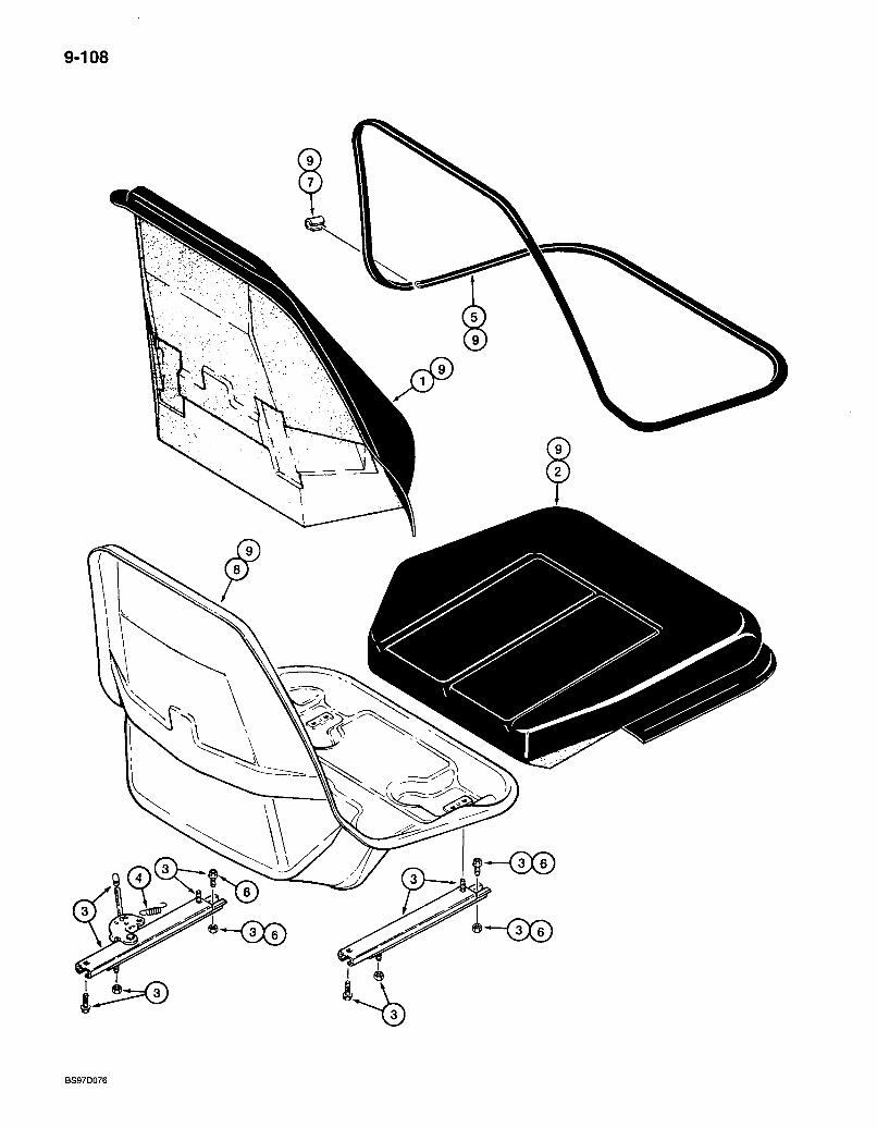
9-108
f-<5©
BS97D076
REF.
1 2 3 4
5 6
7 8 9
PART NO. 185156A1
176926A1 176925A1 116760A1 119171A1
176924A1 ^181169A1
NSS NSS 234223A1
580 Super L Series 2 Loader Backhoe STANDARD SEAT ASSEMBLY
DESCRIPTION SEAT ASSEMBLY - standard, gray vinyl, not serviced as a complete assembly, for service order respective component kits, see page 9-111 for standard support and pedestal
KIT - backrest cushion, gray KIT - seat cushion, gray . . . . KIT - adjuster, seat slide, fore/aft KIT - spring, seat adjuster slide, also includes vertical latch and extension springs used in the standard pedestal on page 9 - 1 1 1 . . . . TRIM - edging, gray, cushion to shell. KIT - cable, fore-aft/swivel mechanism, also includes cable on page 9-111
CLIP - retainer, order N7802 clip kit, see below SHELL - seat frame, order 234223A1 shell, cushion and trim kit, Ref 9 . KIT - seat shell, cushion and trim, includes Ref 1, 2, 5 and 8 . .
9-109
REO'D.
N7802 KIT - clip, includes item 7 clip above, plus 6 additional narrow clips 1
NOTE: Each kit includes an instruction sheet.
Bur 7-3350 Issued February, 1998

9-110
9
A WARNING
^3)
LUBRICATE SWIVEL POST (GREASE FITTING ON SIDE)
REF.
1 2 3 4 5
6 7
580 Super L Series 2 Loader Backhoe 9-111 STANDARD SEAT SUPPORT AND PEDESTAL
PART NO. DESCRIPTION REQ'D. 185156A1 SEAT ASSEMBLY - standard, gray vinyl, includes seat on page 9-109
and support and pedestal below, individual connponent parts not serviced separately, for service order respective kits 1
* 116761A2 KIT - support, base. . . . . . .1 116763A1 KIT - cable, anchor, includes hardware for both ends of cable 1
* 116764A2 KIT - pedestal, includes 219-16 grease fitting 1 * 116766A2 KIT - pedestal box, includes 219-16 grease fitting 1 * 116767A1 KIT - swivel latch, includes (6) lock nuts, (1) push nut and (1) swivel
latch, if used 1 119171A1 KIT - spring, also includes seat slide adjuster spring on page 9-109 1 181169A1 KIT - cable, fore-aft/swivel mechanisnn, also includes (4) nuts on
page 9-109 1 253209A1 KIT - swivel latch, includes (4) lock nuts, (1) rivet, (1) spacer, (1)
washer, (1) push nut and (1) swivel latch, if used 1
NOTE: Each kit includes an instruction sheet.
* NOTE: , Also includes (4) lock nuts for seat adjuster slide on page 9-109.
Bur 7-3350 Issued February, 1998
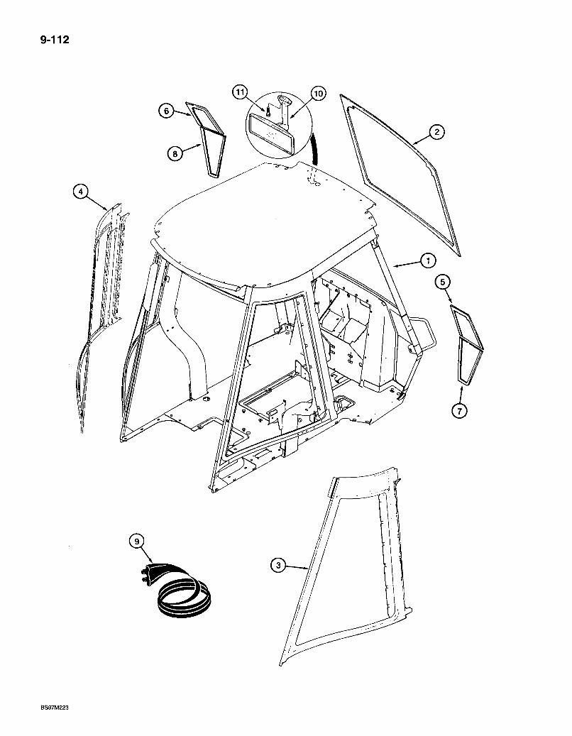
9-112
BS97M223
580 Super L Series 2 Loader Backhoe ROPS CAB AND G L A S S
9-113
REF. 1
1
2 3 4 5 6 7 8 9 10 11
PART NO. 280995A1
280996A1
97290C1 D126204 D126205 107230A1 107233A1 107232A1 107234A1 108513A1 143369A2 286-56520
DESCRIPTION OAB ASSEMBLY - ROPS, operators, complete with heat, order from Machinery Price List, parts list pages 9-113 thru 9-145 CAB ASSEMBLY - ROPS, operators, complete with heat and air conditioning, order from Machinery Price List, parts list pages 9-113 thru 9-145
REQ'D.
GLASS - front windshield GLASS - right-hand rear quarter panel window GLASS - left-hand rear quarter panel window GLASS - knee, upper, right-hand GLASS - knee, upper, left-hand GLASS - knee, lower, right-hand GLASS - knee, lower, left-hand SEAL - 290 mm (11-7/16 inch) long, front knee glass 2 MIRROR - rear view, interior 1 SCREW - self-tapping. Fillister head. No. 10 NC x 1-1/4 inch 2
NOTE: The grab handles are welded to the cab frame and there is no service replacement for these handles.
Bur 7-3350 Issued Febi-uary, 1998
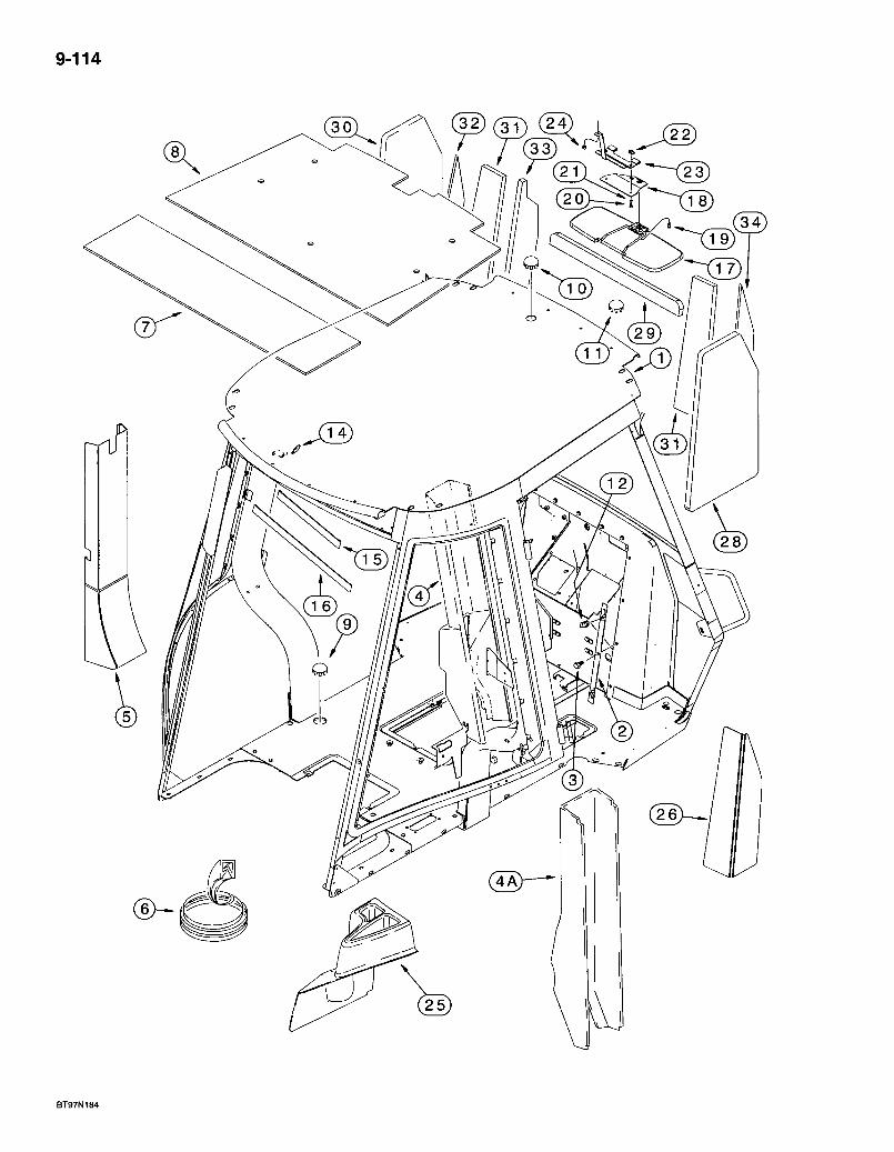
9-114
( 3 2 ) ( 3 1 ) (15
BT97N184
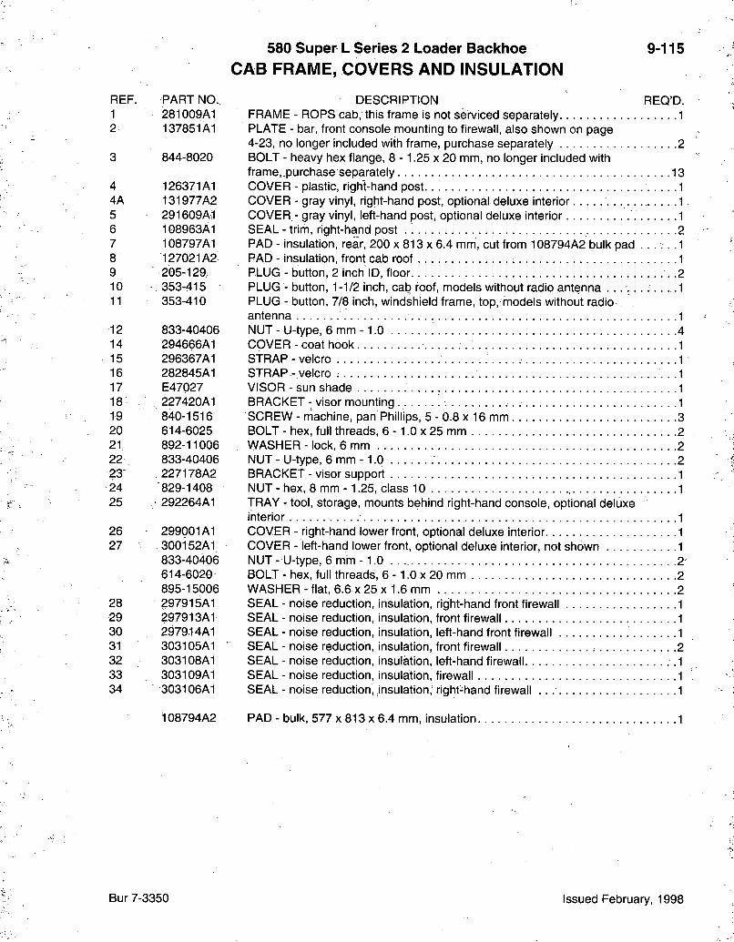
580 Super L Series 2 Loader Backhoe CAB FRAME, COVERS AND INSULATION
9-115
REF. PART NO. 1 281009A1 2 137851A1
3 844-8020
4 126371A1 4A 131977A2 5 291609Ail 6 108963A1 7 108797A1 8 127021A2 9 205-129 10 353-415 11 353-410
12 833-40406 14 294666A1 15 296367A1 16 282845A1 17 E47027 18 227420A1 19 840-1516 20 614-6025 21 892-11006 22 833-40406 23 227178A2 24 829-1408 25 • 292264A1
26 299001A1 27 300152A1
833-40406 614-6020 895-15006
28 297915A1 29 297913A1 30 297914A1 31 303105A1 32 303108A1 33 303109A1 34 303106A1
108794A2
DESCRIPTION REQ'D. FRAME - ROPS cab, this frame is not serviced separately 1 PLATE - bar, front console mounting to firewall, also shown on page 4-23, no longer included with frame, purchase separately 2 BOLT - heavy hex flange, 8 - 1.25 x 20 mm, no longer included with frame,.purchase separately 13 COVER - plastic, right-hand post 1 COVER - gray vinyl, right-hand post, optional deluxe interior 1 COVER - gray vinyl, left-hand post, optional deluxe interior 1 SEAL - trim, right-hand post 2 PAD - insulation, rear, 200 x 813 x 6.4 mm, cut from 108794A2 bulk pad . . . . . .1 PAD - insulation, front cab roof 1 PLUG - button, 2 inch ID, floor .2 PLUG - button, 1-1/2 inch, cab roof, models without radio antenna . . . . . . . . . . . 1 PLUG - button, 7/8 inch, windshield frame, top, models without radio antenna -1 NUT - U-type, 6 mm - 1.0 4 COVER - coat hook 1 STRAP-velcro 1 STRAP - velcro .1 VISOR - sun shade 1 BRACKET - visor mounting 1 SCREW - niachine, pan Phillips, 5 - 0.8 x 16 mm 3 BOLT - hex, full threads, 6 -1.0 x 25 mm 2 WASHER - lock, 6 mm 2 NUT - U-type, 6 mm -1.0 2 BRACKET - visor support 1 NUT - hex, 8 mm -1.25, class 10 1 TRAY - tool, storage, mounts behind right-hand console, optional deluxe interior 1 COVER - right-hand lower front, optional deluxe interior 1 COVER - left-hand lower front, optional deluxe interior, not shown 1 NUT- U-type, 6 mm-1.0 . . 2 BOLT - hex, full threads, 6 -1.0 x 20 mm 2 WASHER - flat, 6.6 x 25 x 1.6 mm 2 SEAL - noise reduction, insulation, right-hand front firewall 1 SEAL - noise reduction, insulation, front firewall 1 SEAL - noise reduction, insulation, left-hand front firewall 1 SEAL - noise reduction, insulation, front firewall 2 SEAL - noise reduction, insulation, left-hand firewall .1 SEAL - noise reduction, insulation, firewall 1 SEAL - noise reduction, insulation, right-hand firewall .1
PAD - bulk, 577 x 813 x 6.4 mm, insulation 1
Bur 7-3350 Issued February, 1998
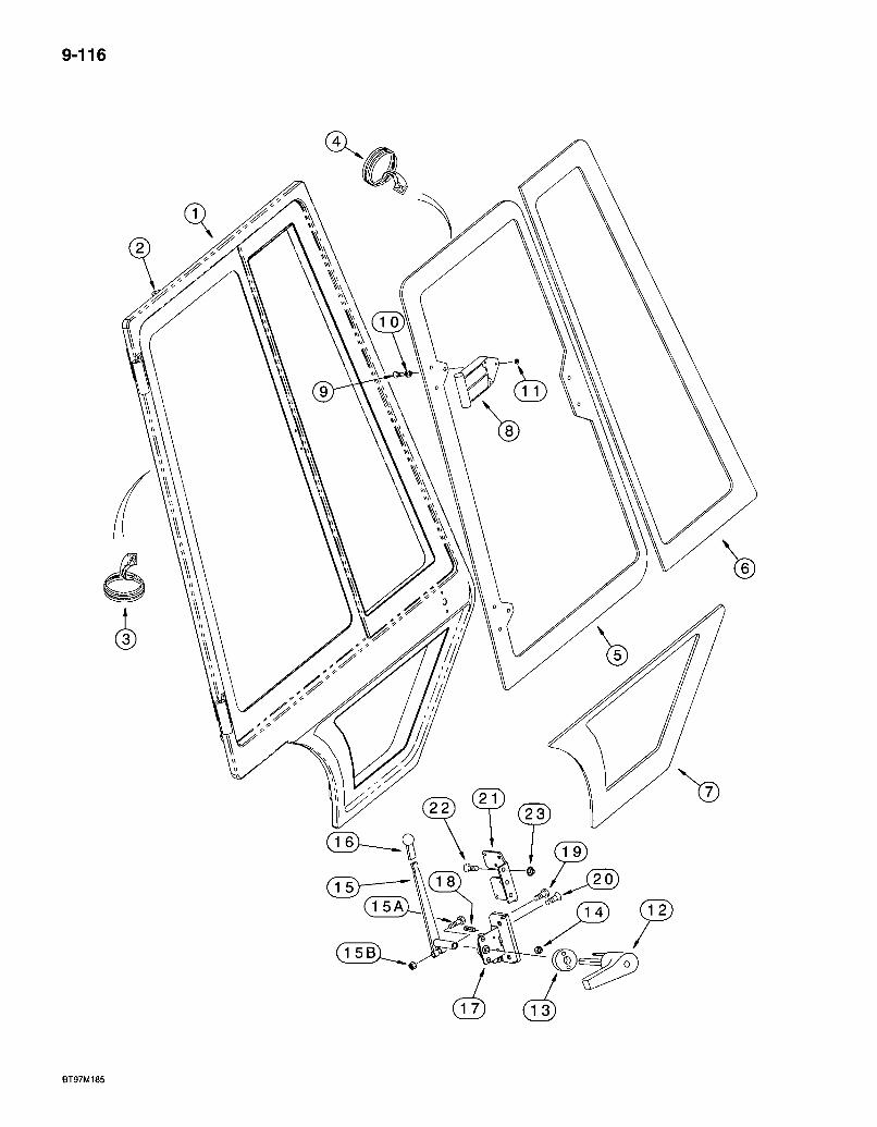
9-116
3
& (p)
BT97M185
580 Super L Series 2 Loader Backlioe LEFT-HAND AND RIGHT-HAND CAB DOORS - EXTERIOR
9-117
REF. PART NO. 1 137869A3 1A 137868A3 2 R53562 3 187582A2
4 R53444
5 R52882 5A R52881 6 R52880 6A R52879 7 R52884 7A R52883 8 R52917 9 142-103
10 F64198
11 F45165
12 196675A2 12A 196673A2 13 F64342 14 231-14109
255450A1
15 255453A1 15A 814-8045 15B 832-10408 16 D135387 17 R55000 17A R55001 18 A180163 19 265-16512
20 137731A1
21 1977401C1 21A 1977402C1 22 443-13112 23 231-5145
DESCRIPTION REQ'D. FRAt\/lE - right-hand door 1 FRAME - left-hand door, not shown 1
BRACKET - cable, welded to left-hand or right-hand door frame 1 SEAL - bulb type, with drain holes, 4585 nfim (180-1/2 inch) long, with self adhesive 2 SEAL - bulb type, 2689 mm (105-7/8 inch) long, left-hand and right-hand window frames 2 GLASS - right-hand door, rear window, tinted GLASS - left-hand door, rear, window, tinted, not shown GLASS - right-hand door, front, tinted GLASS - left-hand door, front, tinted, not shown GLASS - right-hand door, lower, tinted GLASS - left-hand door, lower, tinted, not shown HINGE - glass, door window 4 SCREW - machine, oval Phillips, No. 10 NC x 3/4 inch, left-hand and right-hand door window hinge 12 SPACER - nylon, black, glass to hinge, left-hand and right-hand door window hinge 12 NUT - hex, self-locking, special. No. 10 NC, Teflon coated, left-hand and right-hand door window hinge 12 HANDLE - right-hand door, outer 1 HANDLE - left-hand door, outer, not shown 1 GASKET - door handle, left-hand and right-hand 2 NUT - hex, self-locking. No. 10 NC, left-hand and right-hand handles 4 KIT - service, inner door handle, includes (1 each) Ref 15 - 15B, plus instructions 1
LEVER - inner left-hand or right-hand door latch handle 1 BOLT - hex, 8 - 1.25 x 45 mm 1 NUT - hex, self-locking, 8 mm -1.25 1
KNOB - lever, inner door latch 2 LATCH ASSEMBLY - door, right-hand, rotary 1 LATCH ASSEMBLY - door, left-hand, rotary, not shown 1
SPRING - extension, left-hand or right-hand door latch 1 SCREW - self-tapping, oval Phillips, No. 10-16 x 3/4 inch, left-hand and right-hand door latch 4 SCREW - machine, flat head Phillips, special, 1/4 NC x 1 inch, left-hand and right-hand door latch 8 BRACKET - latch, right-hand rotary 1 BRACKET - latch, left-hand rotary, not shown 1 SCREW - machine, flat Phillips, 5/16 NC x 3/4 inch 6 NUT - hex serrated flange, 5/16 inch NC 6
Bur 7-3350 Issued February, 1998
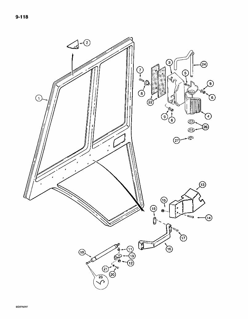
9-118
9 fey %
BS97N097

580 Super L Series 2 Loader Backhoe LEFT-HAND AND RIGHT-HAND CAB DOORS INTERIOR
9-119
REF. PART NO. 1 137868A3 1A 137869A3 2 .R53562 3 281069A1 4 281068A1 5 140-104 6 F45165 7 142-103 8 F64198 9. 195-81023 10 F44881 11 1340345C1 12 230-4215 13 108938A2 13A 108936A2 14 260-16524
15 R53000 16 1958970C1 17 165-129
18 1971368C1 19 1977399C1 20 413-48 21 492-11025 22 R54047 23 F44883 24 291129Ai 25 280336A1 26 895-11008 27 100-3331
DESCRIPTION REQ'D. FRAME - left-hand door. 1 FRAME - right-hand door, not shown 1
BRACKET - cable, welded to left-hand or right-hand door frame 1 HANDLE - door window q . .> 2 LATCH - push type, door window|. 2 SCREW - machine, pan .head Phillips, No., 8 NC x 3/4 inch A NUT - hex, self-locking, special, rilo. 10 NC 8 SCREW - machine, oval Phillips, |No. 10 NC x 3/4 inch 4 SPACER - nylon, black, glass to bracket 4 WASHER - flat, 1/4 x 9/16 x 3/64 inch. 8 CYLINDER - door, left-hand and right-hand 2 STUD - ball, cylinder 2 NUT - hex, self-locking, 5/16 inch' NC 2 PANEL - left-hand door J. , .1 PANEL - right-hand door J . . . • • 1 SCREW - self-tapping, pan Phillies, No-. 10-16 x 1-1/2 inch, black, left-hand arid right-hand door pariels 4 RETAINER - screw, left-hand and right-hand door panels .4 HANDLE-,- left-hand and right-hand inner door . .2 BOLT - hex socket, self-locking, 1/4 NC x 3/4 inch, black, left-hand and right-hand inner door handles 8 PLATE - retainer, left-hand and'right-hand inner door handle .. . : 4 BRACKET - cylinder . i . . . . .'. 2 BOLT - hex, 1/4 NC x 1/2 inch. i. . . 4 WASHER - lock, 1/4 inch." . . . . . . . . . ' . / . 4 SHIM - latch bracket, left-hand and right-hand door window. 4 RETAINER - lock, clip.. .| .2 ROD - window prop, hold open, left-hand 1 ROD - window prop, hold open, right-hand, not shown.. . . . : . . .1 WASHER - flat, 9 x 17 x 1.6 mm 4 RING - E-type, external retaining. No. 31 2
Bur 7-3350 Issued February, 1998

9-120
@
BS97N098

580 Super L Series 2 Loader Bacldioe LEFT-HAND AND RIGHT-HAND CAB DOOR MOUNTING
9-121
REF. PART NO. 1 REF 2 413-6152 3 F64046 4 131-203 6A 495-21038 8 L60224 9 F44881 10 1340345C1 11 230-4215 12 230590A1
12A 230589A1
13 230588A1 14 413-420 15 D36669 16 230-4214 17 281-18712
18 R52735 19 F44748 20 495-81148 21 230-4217 22 107949A1 23 139362A1 24 495-71041 25 832-10410 26 136-154 27 225059A1
228689A1
DESCRIPTION REQ'D. DOOR - cab, see page 9-117 through 9-121 1 BOLT - hex, 3/8 NC x 9-1/2 inch 4 WASHER - thrust, plastic 8 NUT - light hex, self locking, 3/8 inch NC 4 WASHER - flat, 3/8 x 7/8 x 3/32 inch 4 BUMPER - rubber, cab door frame and window latch 4 CYLINDER - door, left-hand and right-hand 2 STUD - ball, cylinder, right-hand door 1 NUT - hex, self-locking, 5/16 inch NC 2 BRACKET - left-hand cab door window retaining, mounts to frame, black, not shown 1 BRACKET - right-hand cab door window retaining, mounts to frame, black .1 LATCH - door window to cab frame 2 BOLT - hex, 1/4 NC x 1-1/4 inch, latch to bracket 2 SPRING - compression, left-hand and right-hand window latch release 2 NUT - hex, self-locking, 1/4 inch NC 2 SCREW - self-tapping, hex washer head, 1/4 NC x 3/4 inch, bracket to frame 6 STRIKER - door latch 2 SPRING - Belleville, washer 2 WASHER - flat, 7/16 x 1-1/4 x 1/8 inch 2 NUT - hex, self-locking, 7/16 inch NC 2 BUSHING - door hinge 8 STUD - upper ball, 10 mm -1.5, cylinder, left-hand door 1 WASHER - flat, 13/32 x 1-1/4 x 3/32 inch 2 NUT - hex, self-locking, 10 mm -1.5 1 PIN - cotter, hair, 7/64 x 1-1/8 inch, mounts to clevis pin welded to frame 4 CABLE - door, upper 2 PIN - clevis, welded to cab frame, not shown 4
Bur 7-3350 Issued February, 1998
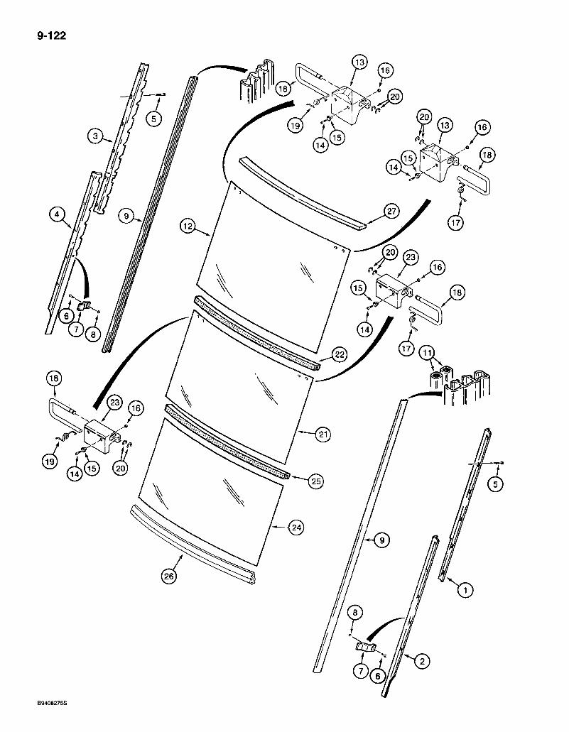
9-122
B9408275S
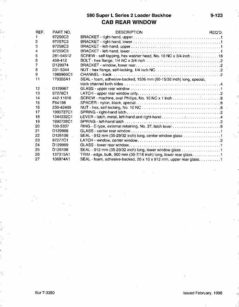
580 Super L Series 2 Loader Backhoe CAB REAR WINDOW
9-123
REF. PART NO. 1 97256C3 2 97257C3 3 97258C3 4 97259C3 5 281-54512 6 458-412 7 D129974 8 231-5344 9 1989960C1 11 179355A1
12 D129967 13 97278C1 14 442-11016 15 F64198 16 230-42409 17 1990727C1 18 1344232C1 19 1990728C1 20 100-3337 21 D129968 22 D126198 23 97277C1 24 D129969 25 D126198 26 137315A1 27 106974A1
DESCRIPTION REQ'D. BRACKET - right-hand, upper 1 BRACKET - right-hand, lower 1 BRACKET - left-hand, upper 1 BRACKET - left-hand, lower 1 SCREW - self-tapping, hex washer head. No. 10 NC x 3/4 inch 18 BOLT - hex flange, 1/4 NC x 3/4 inch 2 BRACKET - window, lower rear 2 NUT - hex flange, self-locking, 1/4 inch NC 2 CHANNEL - track 2 SEAL - foam, adhesive-backed, 1536 mm (60-15/32 inch) long, special, track channel both sides 4 GLASS - upper rear window 1 LATCH - upper rear window only 2 SCREW - machine, oval Phillips, No. 10 NC x 1 inch 8 SPACER - nylon, black, special 8 NUT - hex, self-locking. No. 10 NC 8 SPRING - right-hand latch 2 LEVER - latch, metal, left-hand and right-hand ^ 4 SPRING - left-hand latch 2 RING - E-type, external retaining. No. 37, latch lever 8 GLASS - center rear window 1 SEAL - 912 mm (35-29/32 inch) long, center window glass 1 LATCH - window, center window 2 GLASS - lower rear window 1 SEAL - 912 mm (35-29/32 inch) long, lower window glass 1 TRIM - edge, bulk, 900 mm (35-7/16 inch) long, lower rear glass 1 SEAL - foam, adhesive-backed, 20 x 10 x 912 mm, upper rear glass 1
Bur 7-3350 Issued February, 1998
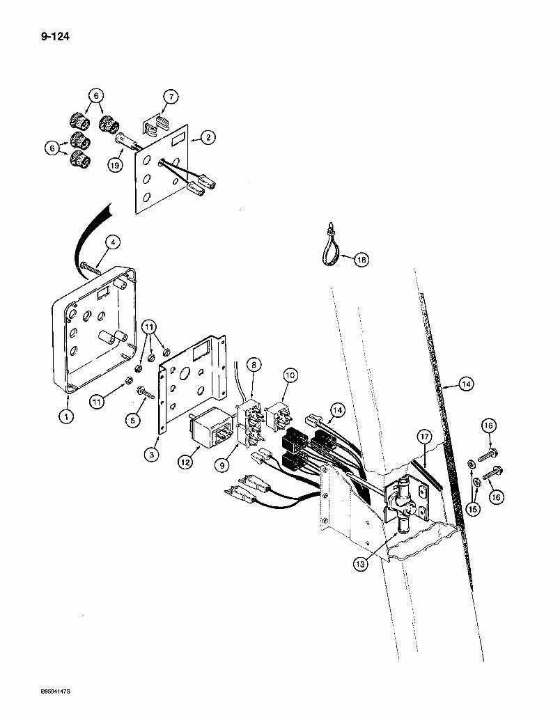
9-124
6
B9504147S
580 Super L Series 2 Loader Backhoe CAB CONTROL PANEL AND WIRING
9-125
REF. PART NO. 1 , 135185A1 2 135183A1
3 136036A1 4 286-56520 5 281-54512 6 111282C1
7 126844A1 8 245258A1 9 R52440
245706C1 10 R52415 11 A42561 12 1340287C1 13 R52483 14 REF 15 895-11008 16 458-412
17 D36179
18 473321 CI 19 1964672C1
F42827
DESCRIPTION REQ'D. PANEL - cab control, includes decal, mounts on right-hand ROPS post . . . . . . . 1
DECAL - instrument symbols, wipers and environmental control, item 3 shown on page 9-155 1
BRACKET - switch support 1 SCREW - self-tapping. Fillister head, No. 10 NC x 1-1/4 inch 4 SCREW - self-tapping, hex washer head, No. 10 NC x 3/4 inch 2 KNOB - control, switch, front and rear wiper, heater, blower, and air conditioner 4-5 PLUG - cab accessory, see page 9-127 for windshield washer switch 1 SWITCH - blower 1 SWITCH - rear wiper 1 PLUG - plastic, rear wiper, blower, windshield wiper, if used, not shown 3 SWITCH - front wiper 1 NUT - retaining, 7/16 inch NC, switch 4 SWITCH - temperature control, air conditioning 1 VALVE - temperature control, heater 1 HARNESS - cab, main, see page 4-31 for cab harness 1 WASHER - flat, 9 x 17 x 1.6 mm 2 BOLT - hex flange, 1/4 NC x 3/4 inch, mounts heater temperature control valve to ROPS post 2 TRIM - edge, 108 mm (4-1/2 inch) long, cut from F42827 bulk trim, control panel bracket, see below 1 STRAP-tie 4 LIGHT - indicator, amber, 14 volt, air conditioning 1
TRIM - edge, bulk, 2946 mm (116 inch) long 1
Bur 7-3350 Issued February, 1998
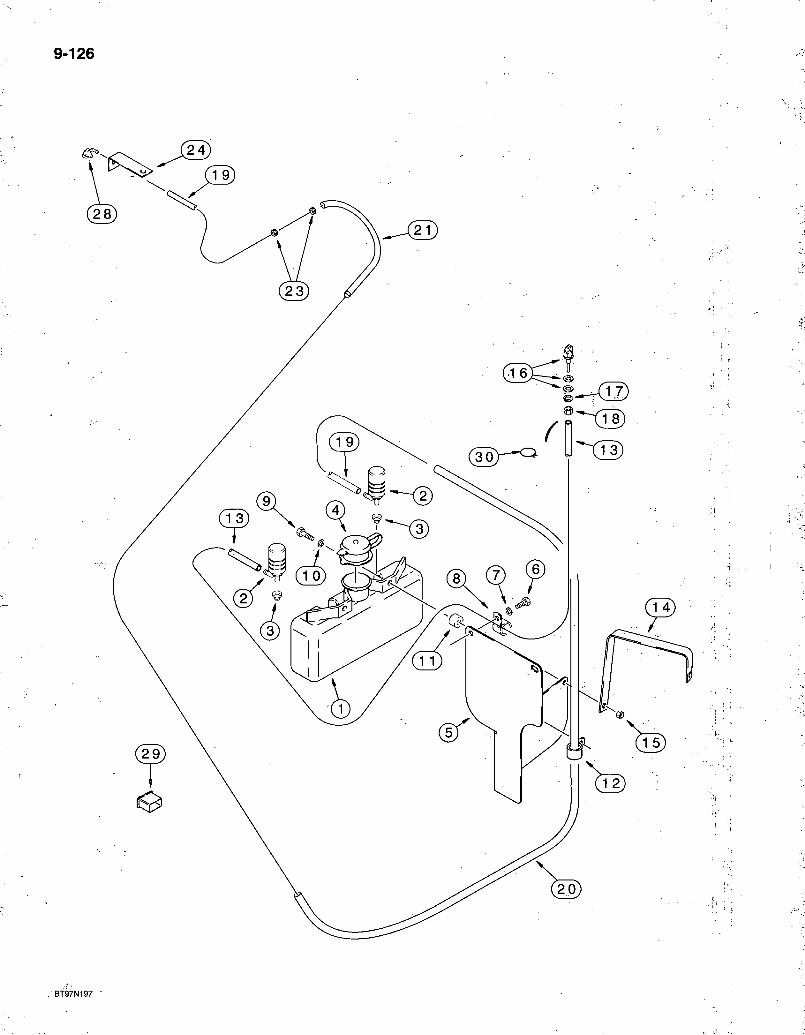
9-126
BT97N197 '
580 Super L Series 2 Loader Backhoe WINDSHIELD WASHERS - FRONT AND REAR
9-127
REF. PART NO. E46560
1 NSS 2 E47238 3 E47239 4 E47240 5 226376A1 6 806-8040 7 895-15008 8 515-2295 9 814-10040 10 895-11010 11 E46561 12 D147383 13 292408A1
14 295597A1 15 832-10410 16 284154A1
17 492-11038 18 425-106 19 226584A1
20 226582A1 21 226580A1 23 E46524 24 305818A1
28 E43769
29 144900A1
30 305578A1
DESCRIPTION REQ'D. RESERVOIR - windshield washer 1
RESERVOIR - windshield washer 1 PUMP - windshield washer 2 GASKET - mounting 2 CAP - reservoir 1
BRACKET - reservoir mounting, mountings to firewall 1 BOLT - hex, self-locking, 10 -1.5 x 40 mm, class 10.9 2 WASHER - flat, 9 x 20 x 1.6 mm 2 CLAMP - P-type, 3/8 inch ID 1 BOLT-hex, 10-1.5x40 mm 2 WASHER - flat, 11 x 20 x 2 mm 2 SPACER - plastic 2 CLAMP - J-type, 5/8 inch diameter 1 HOSE - 850 mm (33-1/2 inch) long, front washer, fixed hoodito reservoir pump closest to the firewall 1 BRACKET - support, uses existing air cleaner mounting hardware 1 NUT - hex, self-locking, 10 mm - 1.5 2 NOZZLE - washer, front, includes steel and rubber washer which are not serviced separately -I WASHER - lock, 3/8 inch 1 NUT - hex, 3/8 inch NC 1 HOSE - 5020 mm (197-11/16 inch) long, rear washer, mounts to reservoir pump located the furthest away from the firewall 1 SLEEVE - hose, 1850 mm (72-7/8 inch), lower hose 1 SLEEVE - hose, 520 mm (20-1/2 inch), upper hose 1 GROMMET - rubber, 8 (5/16) ID x 23 mm (29/32 inch) OD 2 BRACKET - rear nozzle mounting, uses existing lamp mounting hardware 1 NOZZLE - washer, rear, includes rubber gasket which is not serviced separately 1 SWITCH - rocker, windshield washer, front and rear, mounts in cab control panel 1 CLAMP - hose 1
Bur 7-3350 Issued February, 1998

9-128
B9402088S
580 Super L Series 2 Loader Backhoe CAB FRONT WINDSHIELD WIPER
9-129
REF. PART NO A186171
1 A186256 2 N8359 3 N8362 4 N8361 5 L112090 6 N8360 7 N8358 8 N14112 9 N8356 10 L112088 11 L112087 12 L112089 13 L112090 14 L112081 15 R54504 16 D128745 17 *A187909
17A *132024A1
18 19
414-412 492-11025
*1983335C1
* 132025A1
DESCRIPTION REQ'D. WIPER ASSEMBLY - windshield, 12 volt, with bracket, front windshield wiper 1
MOTOR - wiper, 12 volt, windshield wiper 1 BRACKET - windshield wiper assembly 1 SCREW - with washer, special, motor to bracket .3 WASHER - Belleville 1 NUT - hex, special 1 ARM-drive 1 LINK-wiper 1 SHAFT - pivot 1 SCREW - special, pivot shaft to bracket 4
WASHER - special, large, shaft 1 NUT - special, large, shaft 1 WASHER - wave, special, shaft end 1 NUT - hex, special, shaft end 1 CAP - pivot shaft end 1 SPACER - pivot shaft 1 ARM - windshield wiper, 570 mm (22-7/16 inch) long, complete 1 BLADE - wiper arm, complete, used in production, 500 mm (19-11/16 inch) long, not available for service, for complete blade order item 17A, 132024A1 1 BLADE - wiper arm, complete, for blade only, order 132025A1 blade refill, shown below 1 BOLT - hex, 1/4 NF x 3/4 inch 2 WASHER-lock, 1/4 inch 2
BLADE - rubber, 500 mm long, refill for A187909 complete blade, see note, no longer available, order item 17A, 132024A1 1
BLADE - rubber, 500 mm long, refill for 132024A1 complete blade, see note 1
NOTE: See the blade ends in the illustrations for items 17 and 17A to determine which blade to order.
Bur 7-3350 Issued February, 1998
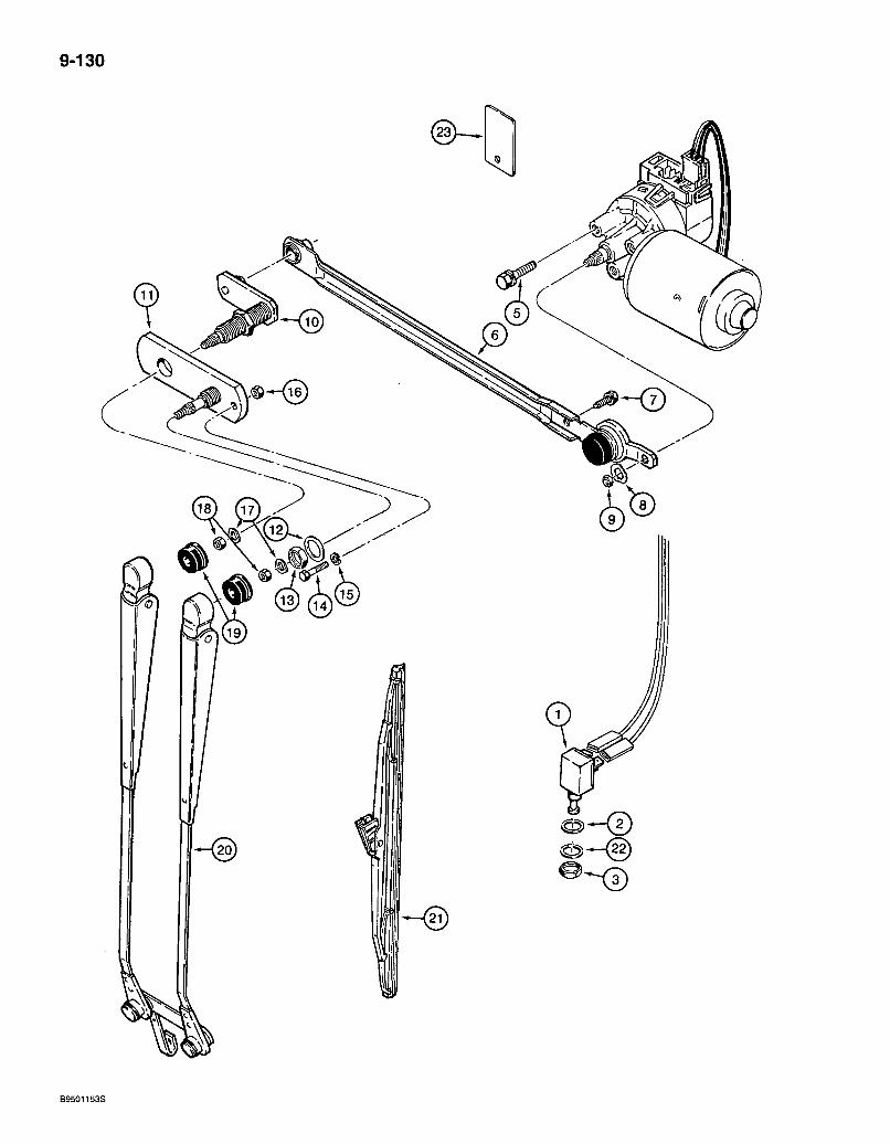
9-130
B9501153S
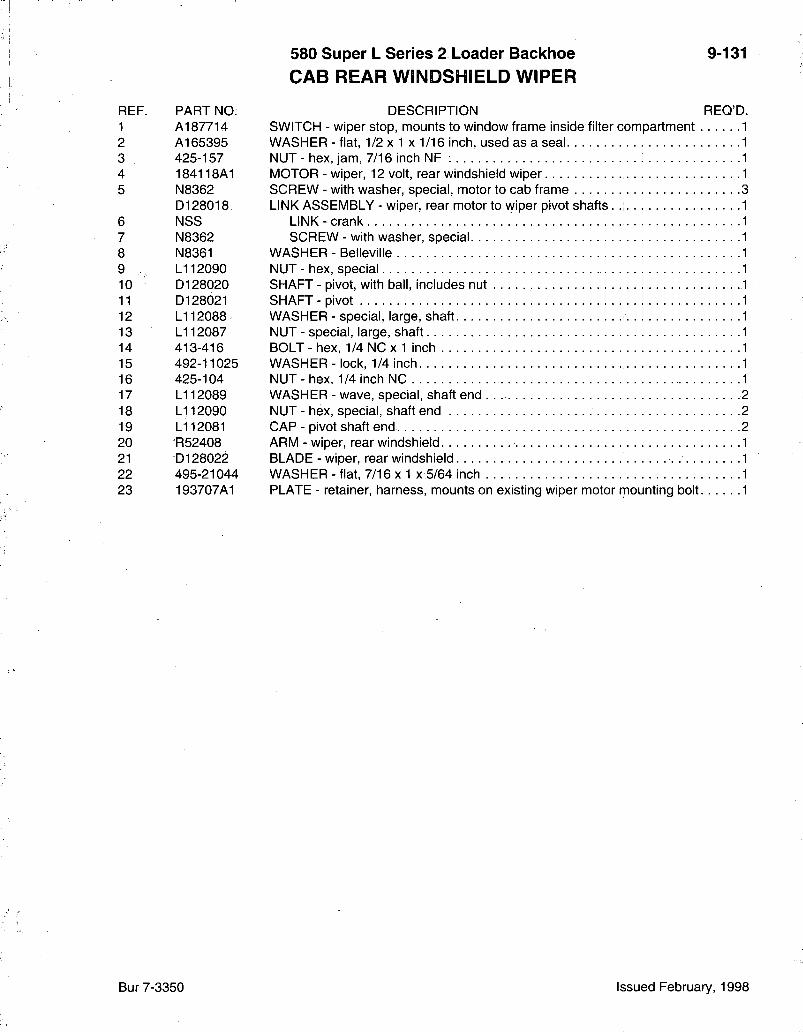
580 Super L Series 2 Loader Backhoe CAB REAR WINDSHIELD WIPER
9-131
REF. PART NO. 1 A187714 2 A165395 3 425-157 4 184118A1 5 N8362
D128018 6 NSS 7 N8362 8 N8361 9 .. L112090 10 D128020 11 D128021 12 L112088 13 L112087 14 413-416 15 492-11025 16 425-104 17 L112089 18 L112090 19 L112081 20 R52408 21 D128022 22 495-21044 23 193707A1
DESCRIPTION REQ'D. SWITCH - wiper stop, mounts to window frame inside filter compartment WASHER - fiat, 1/2 x 1 x 1/16 inch, used as a seal NUT - hex, jam, 7/16 inch NF : MOTOR-wiper, 12 volt, rear windshield wiper SCREW - with washer, special, motor to cab frame LINK ASSEMBLY - wiper, rear motor to wiper pivot shafts .
LINK - crank SCREW - with washer, special
WASHER - Belleville NUT - hex, special SHAFT - pivot, with ball, includes nut SHAFT - pivot WASHER - special, large, shaft NUT - special, large, shaft BOLT-hex, 1/4NCx1 inch WASHER-lock, 1/4 inch NUT-hex, 1/4 inch NC WASHER - wave, special, shaft end . 2 NUT - hex, special, shaft end 2 CAP - pivot shaft end 2 ARM - wiper, rear windshield 1 BLADE - wiper, rear windshield 1 WASHER - flat, 7/16x1 x 5/64 inch 1 PLATE - retainer, harness, mounts on existing wiper motor mounting bolt 1
Bur 7-3350 Issued February, 1998

9-132
BT97M005
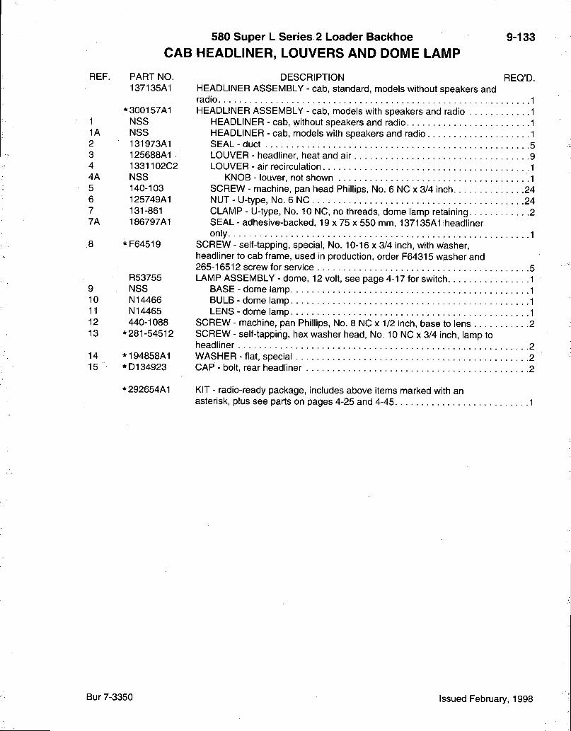
580 Super L Series 2 Loader Backhoe CAB HEADLINER, LOUVERS AND DOME LAMP
9-133
REF.
1 1A 2 3 4 4A 5 6 7
7A
8
9 10 11 12 13
14 15
PART NO. 137135A1
*300157A1 NSS NSS 131973A1 125688A1 1331102C2 NSS 140-103 125749A1 131-861 186797A1
*F64519
R53755 NSS N14466 N14465 440-1088
*281-54512
*194858A1 *D134923
*292654A1
DESCRIPTION REQ'D. HEADLINER ASSEMBLY - cab, standard, models without speakers and radio 1 HEADLINER ASSEMBLY - cab, models with speakers and radio 1
HEADLINER - cab, without speakers and radio 1 HEADLINER - cab, models with speakers and radio 1 SEAL - duct 5 LOUVER - headliner, heat and air 9 LOUVER - air recirculation .1
KNOB - louver, not shown 1 SCREW - machine, pan head Phillips, No. 6 NC x 3/4 inch 24 NUT-U-type, No. 6 NC 24 CLAMP - U-type, No. 10 NC, no threads, dome lamp retaining 2 SEAL - adhesive-backed, 19 x 75 x 550 mm, 137135A1 iheadliner only 1
SCREW - self-tapping, special, No. 10-16 x 3/4 inch, with washer, headliner to cab frame, used in production, order F64315 washer and 265-16512 screw for service 5 LAMP ASSEMBLY - dome, 12 volt, see page 4-17 for switch 1
BASE - dome lamp 1 BULB - dome lamp 1 LENS - dome lamp 1
SCREW - machine, pan Phillips, No. 8 NC x 1/2 inch, base to lens 2 SCREW - self-tapping, hex washer head. No. 10 NC x 3/4 inch, lamp to headliner 2 WASHER - flat, special 2 CAP - bolt, rear headliner 2
KIT - radio-ready package, includes above items marked with an asterisk, plus see parts on pages 4-25 and 4-45 1
Bur 7-3350 Issued February, 1998

9-134
BT97M153

580 Super L Series 2 Loader Bacl<hoe CAB AIR FILTER
9-135
REF. PART NO. 1 139768A1 2 123206A2 3 461-33148 4 495-81121 5 140327A1 7 281-54712 8 243603A1
DESCRIPTION REQ'D. FILTER - air, complete, includes gasket 2 BRACKET - right-hand, air filter retainer BOLT - hex socket, 5/16 NC x 3 inch WASHER-flat, 11/32 x 1-1/2 x 1/16 inch SPACER - filter SCREW - self tapping, hex washer head, 1/4 NC x 3/4 inch SCREEN - filter, rear
Bur 7-3350 Issued February, 1998
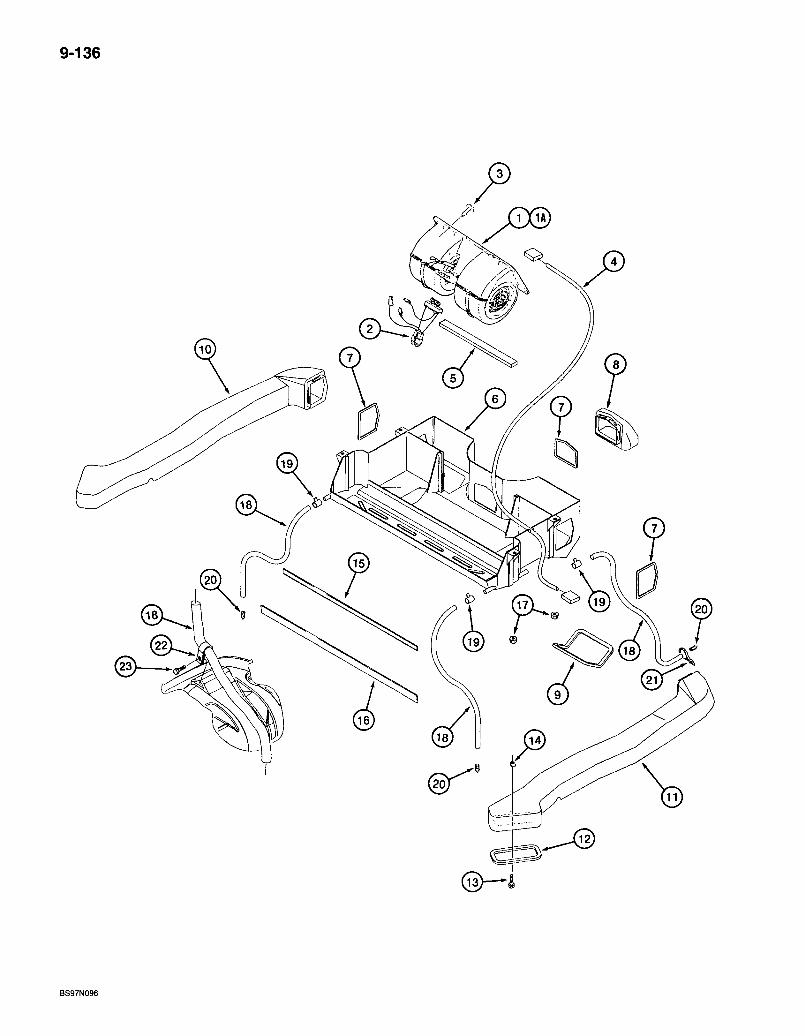
9-136
BS97N096
580 Super L Series 2 Loader Backhoe CAB
BLOWER HOUSING, HEAT AND AIR VENTILATION DUCTS AND DRAIN LINES ^
9-137
REF. PART NO. 1 134049202
1A 1977564C2 2 1343938C2 3 182697A1 4 189404A1 5 181981A1 6 134125A1 7 128406A1 8 13lb39A1 9 131974A1 10 131041A1 11 131042A1 12 131973A1 13 845^6020 14 833-40406 15 1987097C1
16 1987096C1
17 832-10408 18 . 127073A1
19 214-1404 20 .109239C2 21 LI 8337
22 184289A1 23 282-16512
DESCRIPTION REQ'D. BLOWER ASSEMBLY - air, cab, component parts not serviced separately, used in production, for service order 1977564C2 blower assembly and 1343938C1 resistor, items 1A and 2 below 1 BLOWER - cab, air, component parts not serviced separately ; . . .1 RESISTOR - blower 1 RETAINER - plastic fastener 5 HARNESS - jumper, blower 1 SEAL - adhesive-backed, 6 (5/16) x 20 (51/64) x 355 mm (14 inch) long. . . 1 HOUSING - ventilation, heat and air 1 SEAL - ventilation housing to duct 3 DUCT - small, front 1 SEAL - ventilation housing, lower front 2 DUCT - left-hand, large 1 DUCT - right-hand, large 1 SEAL-duct 2 BOLT - heavy hex flange, 6 -1.0 x 20 mm . . 2 NUT-U-type, 6mm-1.0 2 SEAL - 9 (23/64) x 19 (3/4) x 735 mm (29 inch) long, air conditioning drain pan .1 SEAL - 9 (23/64) x 19 (3/4) x 765 mm (30-1/8.inch) long, air conditioning drain pan 1 NUT - hex, self-locking, 8 mm -1.25 . 4 HOSE - 13 (1/2) x 16 (5/8) x 2850 mm (112-13/64 inch) long, front and rear drain 4 CLAMP-adj, 1/4-5/8 inch dia 4 VALVE-check, drain 4 STRAP - tie, 15 inch, nylon, retaining, retain front drain hoses to hydraulic lines 2 CLAMP - hose, mounts on left-hand fender 1 SCREW - self-drilling tapping, hex washer head. No. 10-16 x 3/4 inch. Teflon 1
Bur 7-3350 Issued February, 1998
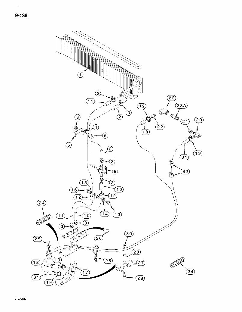
9-138
580 Super L Series 2 Loader Backhoe CAB
*HEATER
9-139
REF. 1
3 4 5 6 8 9
10
11
12 13 14 15 16 17 , 18
19 20 21 22 23 23A .24 25. 26
27 28 29 30 31
32
PART NO. DESCRIPTION REQ'D. 131124A1 CORE - heater, mounts in blower housing box, seal mounts on top of
heater core on models with heater only, see page 9-141 for seal 1 128412A1 HOSE -1100 mm (43-5/16 inch) long, cut from 97252CX bulk hose,
heater core to temperature control valve 1 1954736C1 CLAMP - adjustable, hose 6 L50062 CLAMP - P-type 2 R53634 CLAMP - hose, included in air conditioner package .2 126907A1 SPACER - hose. 2 825-2408 NUT - hex flange, 8 mm - 1.25 2 R52483 VALVE - temperature control, heater, see page 9-125 for mounting
hardware • -1 128410A1 HOSE - 925 mm (36-27/64 inch) long, cut form 97252CX bulk hose,
temperature control valve to floor 1 128411A1 HOSE - 2030 mm (79-15/16 inch) long, cut from 97252CX bulk hose,
heater core to floor 1 L50062 CLAMP - P-type, hose 2 614-8025 BOLT - hex, full threads, 8 - 1.25 x 25 mm 1 895-11008 WASHER - flat, 9 x 17 x 1.6 mm 1 892-11008 WASHER - lock, 8 mm 1 829-1408 NUT - hex, 8 mm -1.25, class 10 . . . 1 190675A1' TUBE - heater elbow at f loor. . . . . . 2 225713A1 HOSE - 2400 mm (94 inch) long, cut from 97252CX bulk hose, floor to
left-hand side of engine, short 1 214-1410 CLAMP - adj, 9/16 - 1-1/16 inch dia. .4 301803R1 VALVE - shutoff, shutoff, right-hand side of engine 1 221-89 REDUCER - pipe, 1/2 male X 3/8 inch female, replaces existing plug 1 LI 7985 NIPPLE - 3/8 inch PT, left-hand side of engine . 1 221-1382 ELBOW-street, 90 degree 1/2x3/8 inch PT 1 221-190 NIPPLE - straight, 1/2 PT x 2 inch, replaces existing plug 1 D132982 SLEEVE - hose guard 4 L18337 STRAP - tie, 15 inch, nylon, retaining 3 353-406 PLUG - button, 5/8 inch,'air conditioning drain, used on models with
heat only 2 D143427 CLAMP-tube 1 614-8030 BOLT- hex, full threads, 8 - 1.25 X 30 mm 1 D143417 SPACER - 10 IDx 16 0D x6 mm long 1 825-2408 NUT - hex flange, 8 mm -1.25 1 225714A1 HOSE - 3300 mm (130 inch) long, cut from 97252CX bulk hose,
right-hand side of engine 1 D88052 CLAMP - P-type, 1 inch ID, uses existing bellhousing hardware .2
97252CX HOSE - bulk, 16 (5/8) x 25 (1) x 15240 mm (600 inch) long 1
* NOTE: See page 9-141 for hose clamping at floor plate.
Bur 7-3350 Issued February, 1998

9-140
BS97N099
580 Super L Series 2 Loader Backhoe CAB
*EVAPORATOR CORE AIR CONDITIONING LINES
9-141
REF. 1 2 3 4 5
7 8 9 10 11 12 13 14 15
16 17 18 19 20 21 22
23 24 25 26 27
PART NO. 13li27A2 1990756C2 128485A1 128484A1 181980A1
83822C1
190599A1 128485A1 128483A1 1250594Ci 1250594C1 122553A1 122579A1 1340287C1 124727A1
128483A1 LI 8337 D143427 614-8030 D143417 825-2408 124011A1
123980A1 181979A1 845-6020
. 833-40406 825-2406
1954475C1
DESCRIPTION REQ'D. CORE ASSEMBLY - evaporator 1
VALVE - expansion 1 O-RING - 9/16 ID x 1/16 inch wide. . 1 O-RING - 7/16 ID X 1/16 inch wide 1
SEAL - adhesive-backed, 19 (3/4) x 19 (3/4) x 680 mm (26-3/4 inch) long, apply seal to top of evaporator core on models with heat and air conditioning • -1 TAPE - 610 mm (24 inch) long, cut from 1954475C1 bulk tape, insulation, expansion valve and hoses at expansion valve 3 HOSE - suction 1
O-RING - 9/16 ID X 1/16 inch wide, hose end 1 O-RING-5/16 IDx 1/16 inch wide, hose valve core 1 VALVE - core, hose, low pressure switch 1 VALVE - core, hose, low side service port 1 CAP - sealing 1
SWITCH - low pressure 1, SWITCH - temperature control, air conditioning 1 HOSE - 3200 mm (126 inch) long, pressure, liquid line, attaches to item 24 hose on page 9-143 1
O-RING - 5/16 ID X 1/16 inch wide, hose end 1 STRAP - tie, 15 inch, nylon, retaining UAR CLAMP - tube 2 BOLT - hex, full threads, 8 - 1.25 x,30 mm 2 SPACER - 10 ID x 16 OD x 6 mm long, hose clamp 2 NUT - hex flange, 8 mm -1.25 2 GASKET - at cab floor, heat or air conditioned models, trim[center of gasket for air conditioned units 1 CLAMP - heater and air conditioning hoses 2 SEAL-foam 2 BOLT - heavy hex flange, 6 - 1 .O x 20 mm 6 NUT-U-type, 6 mm - 1.0 4 NUT - hex flange, 6 mm -1 2
TAPE - bulk, 63.5 (2-1/2) x 9150 (360) x 3 mm (1/8 inch) thick, insulation 1
* NOTE: Also see page 9-139 for hose clamping.
Bur 7-3350 Issued February, 1998
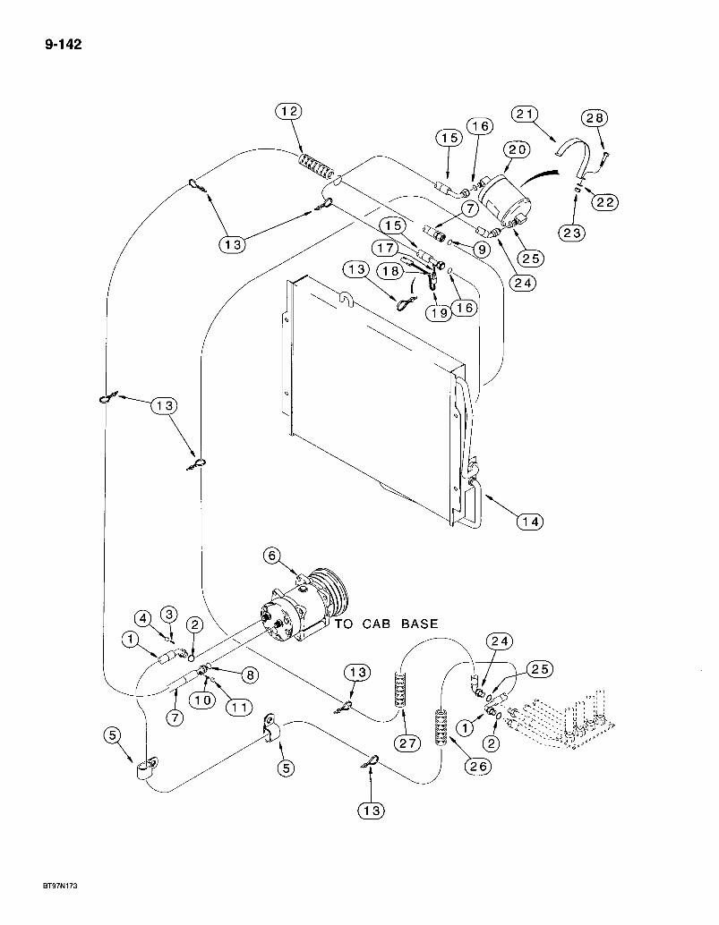
9-142
TO CAB BASE
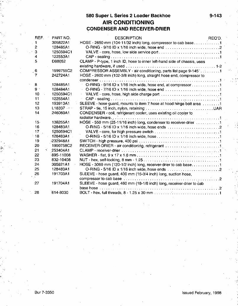
580 Super L Series 2 Loader Backhoe AIR CONDmONING
CONDENSER AND RECEIVER-DRIER
9-143
REF. PART NO. 1 305822A1 2 128485A1 3 1250594C1 4 122553A1 5 D88052
6 1999755C2 7 242724A1
8 128485A1 9 128484A1 10 1250594C1 11 122554A1 12 193913A1 13 LI 8337 -14 246060A1
15 138255A1 16 128483A1 17 1250594C1 18 128483A1 19 232948A1 20 1990758C2 21 253404A1 22 895-11008 23 832-10408 24 305821A1 25 128483A1 26 191703A1
27 191704A1
28 614-8030
DESCRIPTION REQ'D. HOSE - 2650 mm (104-11/32 inch) long, compressor to cab base 1
O-RING - 9/16 ID X 1/16 inch wide, hose end 2 VALVE - core, hose, low side service port 1 CAP - sealing 1
CLAMP - P-type, 1 inch ID, hose to inner left-hand side of chassis, uses existing hardware, if used 1-2 COMPRESSOR ASSEMBLY - ajr conditioning, parts list page 9-145 . . 1 HOSE - 2600 mm (102-3/8 inch) long, straight hose end, compressor to condenser 1
O-RING - 9/16 ID X 1/16 inch wide, hose end, at compressor 1 O-RING - 7/16 ID X 1/16 inch wide, hose end 1 VALVE - core, hose, high side charge port . . . .1 CAP-sealing 1
SLEEVE - hose guard, mounts to item 7 hose at hood hinge bolt area 1 STRAP - tie, 15 inch, nylon, retaining UAR CONDENSER - coil, refrigerant cooler, uses existing oil cooler to radiator hardware. ,.. : 1 HOSE - 550 mm (25-11/16 inch) long, condenser to receiver-drier 1
O-RING - 5/16 ID X 1/16 inch wide, hose ends . 2 VALVE - core, for high pressure switch 1 O-RING - 5/16 ID X 1/16 inch wide, hose .1
SWITCH - high pressure, 400 psi . . .1 RECEIVER-DRIER - air conditioning, refrigerant 1 CLAMP - receiver-drier .1 WASHER - flat, 9 x 17 x 1.6 mm . . . .1 NUT - hex, self-locking, 8 mm -1.25 1 HOSE - 3060 mm (120-1/2 inch) long, receiver-drier to cab base 1
O-RING - 5/16 ID X 1/16 inch wide, hose ends 2 SLEEVE - hose guard, 400 mm (15-3/4 inch) long, suction hose, compressor to cab base .2 SLEEVE - hose guard, 460 mm (18-1/8 inch) long, receiver-drier to cab base hose .2 BOLT - hex, full threads, 8 - 1.25 x 30 mm 1
Bur 7-3350 Issued February, 1998

9-144
@
® /
BS97N174

580 Super L Series 2 Loader Backhoe AIR CONDITIONING
COMPRESSOR MOUNTING AND DRIVE
9-145
REF. PARTNO. 1999755G2
' 1 NSS 2 135324A1 3 A49667 4 128483A1 5 LI 8337 6 A189284
6A 196050A1
7 •277546A1 7A S80928 8 827-10130 9 896-11010 12 304530A1 13 627-10030 14 896-11010 15 A184614; 16 827-10040 18 304527A1 19 827-10110 22 896-11010 23 832-10410 24 627-10035 26 896-11010 27 D147383 28 304525A1 29 304528A1
DESCRIPTION REQ'D. COMPRESSOR ASSEMBLY - air conditioning 1
COMPRESSOR - air conditioning . . 1 CLUTCH ASSEMBLY - compressor 1 PLUG - hex, oil filler .1 0-RING - 5/16 ID X 1/16 inch wide, plug 1
STRAP - tie, 15 inch, nylon, retaining, compressor wire . . . . 2 PULLEY - air conditioner compressor drive, without powershift transmission 1 PULLEY - air conditioner compressor drive, with powershift^ transmission, not shown 1 BELT - drive, compressor, without powershift transmission 1 BELT - drive, compressor, with powershift transmission, not shown .1 BOLT - hex, 10 - 1.5 x 130 mm, class 10.9. 1 WASHER - flat, 11 x 21 x 2.5 mm, hardened 5 BRACKET - compressor mounting 1 BOLT - hex, full threads, 10 -1.5 x 30 mm, class 10.9 2 WASHER - flat, 11 x 21 x 2.5 mm, hardened 2 BLOCK - bracket support 1 BOLT - hex, 10 - 1.5 x 40 mm, class 10.9 2 STRAP - compressor adjusting . . . . . . . | 2 BOLT .hex, 10-1.5 x 110 mm, class 10.9 . 1 WASHER - flat, 11 X 21 X 2.5 mm, hardened 6 NUT-hex, self-locking, 10mm-1.5 4 BOLT - hex, full threads, 10 - 1.5 x 35 mm, class 10:9 ' 4 WASHER - flat, 11 X 21 X 2.5 mm, hardened 3 CLAMP - J-type, main engine harness to compressor bracket . .1 BRACKET - compressor mounting 1 SPACER-short 1
Bur 7-3350 Issued February, 1998
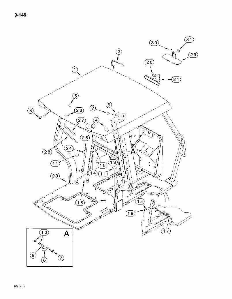
9-146
BT97N171
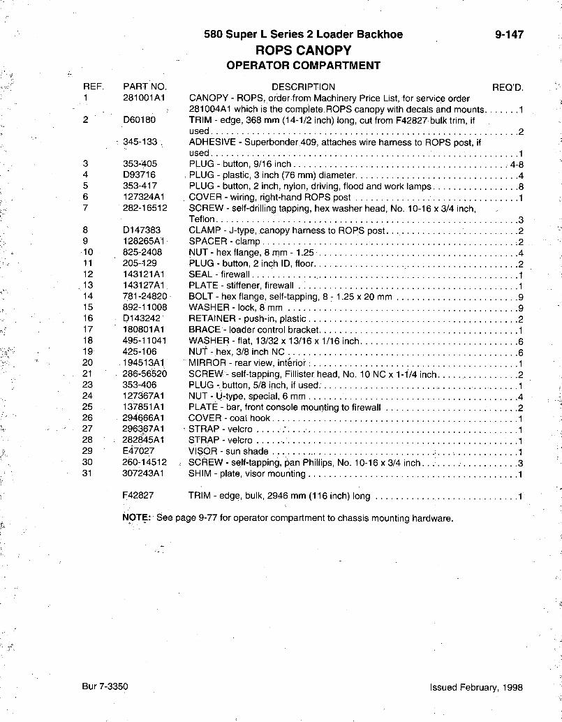
580 Super L Series 2 Loader Backhoe ROPS CANOPY
OPERATOR COMPARTMENT
9-147
REF. PART NO. DESCRIPTION REQ'D. 1 281001A1 CANOPY - ROPS, order from Machinery Price List, for service order
281004A1 which is the complete ROPS canopy with decals and mounts 1 2 D60180 TRIM-edge, 368 mm (14-1/2 inch) long, cut from F42827 bulk trim, if
used 2 ^ 345-133 , ADHESIVE - Superbonder,409, attaches wire harness to ROPS post, if
used 1 3 353-405 PLUG - button, 9/16 inch .4-8 4 D93716 . PLUG - plastic, 3 inch (76 mm) diameter 4 5 353-417 PLUG - button, 2 inch, nylon, driving, flood and work lamps. 8 6 127324A1 COVER - wiring, right-hand ROPS post 1 7 282-16512 SCREW - self-drilling tapping, hex washer head, No. 10-16 x 3/4 inch.
Teflon 3 8 D147383 CLAMP - J-type, canopy harness to ROPS post. . 2 9 128265A1 SPACER - clamp 2 10 825-2408 NUT - hex flange, 8 mm - 1.25 4 11 205-129 PLUG - button, 2 inch ID, floor 2 12 143121A1 SEAL - firewall.. 1 13 143127A1 PLATE - stiffener, firewall . .1 14 781 -24820 BOLT - hex flange, self-tapping, 8 - 1.25 x 20 mm 9 15 892-11008 WASHER - lock, 8 mm 9 16 D143242 RETAINER - push-in, plastic 2 17 180801A1 BRACE - loader control bracket 1 18 495-11041 WASHER-flat, 13/32 X 13/16 x 1/16 inch 6 19 425-106 NUT - hex, 3/8 inch NC 6 20 194513A1 MIRROR - rear view, interior; 1 21 . 286-56520 SCREW - self-tapping. Fillister head, No. 10 NC x 1 -1/4 inch 2 23 353-406 PLUG - button, 5/8 inch, if used. . .1 24 127367A1 NUT - U-type, special, 6 mm 4 25 137851A1 PLATE - bar, front console mounting to firewall 2 26 294666A1 COVER - coat hook 1 27 296367A1 ^ STRAP - velcro 1 28 . 282845A1 STRAP - velcro . .1 29 E47027 VISOR - sun shade 1 30 260-14512 . SCREW - self-tapping, pan Phillips, No. 10-16 x 3/4 inch. . . 3 31 307243A1 SHIM - plate, visor mounting 1
F42827 TRIM-edge, bulk, 2946 mm (116 inch) long 1
NOTE: See page 9-77 for operator compartment to chassis mounting hardware.
Bur 7-3350 Issued February, 1998
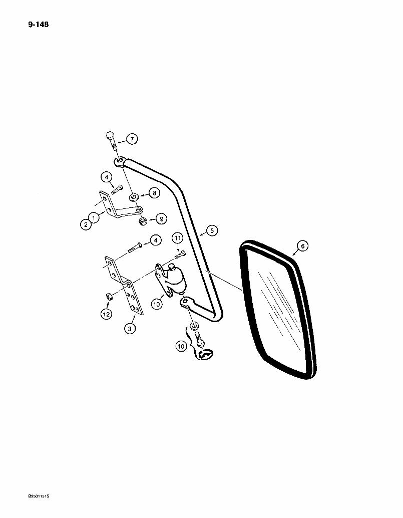
9-148
B9501151S
580 Super L Series 2 Loader Backhoe REAR VIEW MIRROR
POPS CAB MODELS - EXTERIOR
9-149
REF. . PARTNO. "D102964
1 D142084 2 D142085 3 D142083 4 281-54712 5 D142086 6 R54682 7 413:-516 8 Al67037
- 9 ' 231-4115 10 D142144 11 413r412 12 231-1444
. DESCRIPTION REQ'D. KIT - mirror, rear view 1
BRACKET - mirror, right-hand upper 1 BRACKET - mirror, left-hand upper, not shown .1 BRACKET - mirror, lower 2 SCREW - self tapping, hex washer head, 1/4 NC x 3/4 inch 8 SUPPORT - mirror. 2 MIRROR - rear view, exterior. 2 BOLT - hex, 5/16 NC x 1 inch 2 WASHER - nylon 2 NUT - hex, self-locl<ing, 5/16 inch NC . . . . 2 KNUCKLE - support pivot, includes hardware 2 BOLT - hex, 1/4 NC x 3/4 inch • • -6 NUT - hex, self-locking, 1/4 inch NC . . , • • • -6
Bur 7-3350 Issued February, 1998
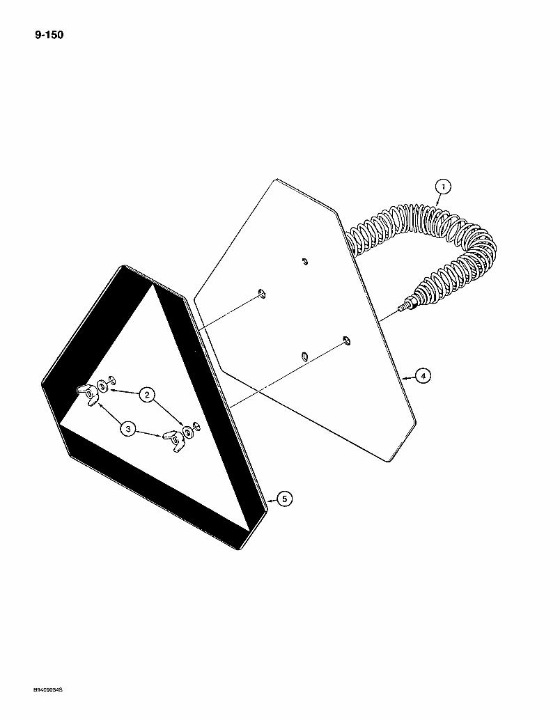
9-150
B9409034S
580 Super L Series 2 Loader Backhoe 9-151 SLOW MOVING VEHICLE EMBLEM
REF. PART NO. DESCRIPTION REQ'D. 1 D52564 SPRING - emblem retaining 1 2 495-11028 WASHER - flat, 9/32 x 5/8 x 1/16 inch 2 3 126177 NUT - wing, 1/4 inch NC 2 4 D123347 EMBLEM - plate and decal, slow moving vehicle 1 5 321-4311 DECAL-SMV emblem 1
Bur 7-3350 Issued February, 1998
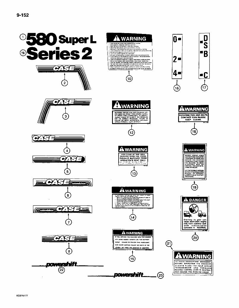
9-152
®580SuperL AWARNING 0" S
• B 2 - • B
4 - • C
4
^WARNING MriEMES COMTAIN *C10 AND CiPLOSlVE GAS EXPLOaON CAN nCSULT FROM SPARKS FLAMES, on WRONG CABL£ COMNECIIONS TO CONNECT JUMPER CABLES OR CWAftCER SEE MAHUAUSl ro» THE conntCT pnoctDURE wtLUflt lO FOLLOW TMt ABOVE rNSTBuCTIONS CAN CAUSE SCMOUS PERSONAL INJUR* OP OEATH
(3)
A W A R N I N G KEEP CLEAR OF THIS AREA
SWINaiNO BOOM CAN CRUSH. OPERATE BACKHOE FROM OPERATOR'S SEAT ONLY.
^ ^ ^ ^ ^
i k w A R N I N G
r-rrm AWARNING » VOU aiAVlCI TMt MACHMI WTTH IMI MIAMI Un AHMI RAttlO. ALWATI U H TNI SUPPOST
CAR CAUII IIHIOUS UUUR* OR MATH W TMl
lOAOIB ANHS AMI lOvMAte •» ACCIOIMT
A W A R N I I M G ROTATING FAN AND BELTS.]
CONTACT CAN INJURE. KEEP C L E A R .
(3)
A W A R N I N G
WRONO iUHPIR CASH CONNCCTIOK* TO t T M m TERyrNALS OR •HORTINQ
TERMINAL* CAM C A U I I THE HACHIWI T O MOVI SUDDEHIT O U T O P CONTROL. T O U CAN Bl IN-juneo on K U . E O .
SHOWN IMTWO«IuTOM MANUAL TO C O N N I C T JUMPER CABLE! TO »TART THE ENClNi.
A DANGER
Starting in gear can cause death.Stvt angine only from operator seat with t ransmiss ion comrolls) in NEUTHAL.
(a)
iJOOMMBfSfl i f t .
iJOOMMCfSlM/L
• w a r n i n g TO AVOID INADVCRTAfTT MaVEMCNT. B E F O R E O P I R A T I h Q T H I B A C K H O E A L W A Y S P L A C E T H E F O U R S P E E D T R A N S M I S S I O N AND F O R W A R D R E V E R S E CONTROL LEVER IN NEUTRAL AND tNGAQE THE PARmwQ B R A K I
BS97N177
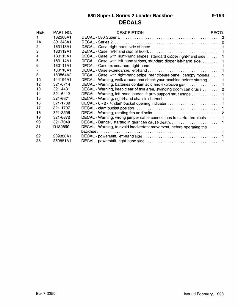
580 Super L Series 2 Loader Backhoe D E C A L S
9-153
REF. PART NO 1 182368A1 1A 301343A1 2 183113A1 3 183112A1 4 183115A1 5 183114A1 6 183111A1 7 183110A1 8 183864A2 10 144194A1 12 321-6714 13 321-4481 14 321-6413 15 321-6671 16 321-1708 17 321-1707 18 321-3596 19 321-6872 20 321-7040 21 D150899
22 239880A1 23 239881A1
DECAL• DECAL• DECAL• DECAL• DECAL-DECAL-DECAL-DECAL-DECAL-DECAL-DECAL-DECAL-DECAL-DECAL-DECAL-DECAL-DECAL-DECAL-DECAL-DECAL-backhoe DECAL-DECAL-
DESCRIPTION REQ'D. 580 Super L 2 Series 2 2 Case, right-hand side of hood Case, left-hand side of hood Case, with right-hand stripes, standard dipper right-hand side Case, with left-hand stripes, standard dipper left-hand side Case extendahoe, right-hand Case extendahoe, left-hand Case, with right-hand stripe, rear closure panel, canopy models Warning, walk around and check your machine before starting Warning, batteries contain acid and explosive gas Warning, keep clear of this area, swinging boom can crush Warning, left-hand loader lift arm support strut usage Warning, right-hand chassis channel 0 - 2 - 4 , clam bucket opening indicator clam bucket position Warning, rotating fan and belts Warning, wrong jumper cable connections to starter terminals Danger, starting in gear can cause death Warning, to avoid inadvertant movement, before operating the
powershift, left-hand side . powershift, right-hand side
Bur 7-3350 Issued February, 1998
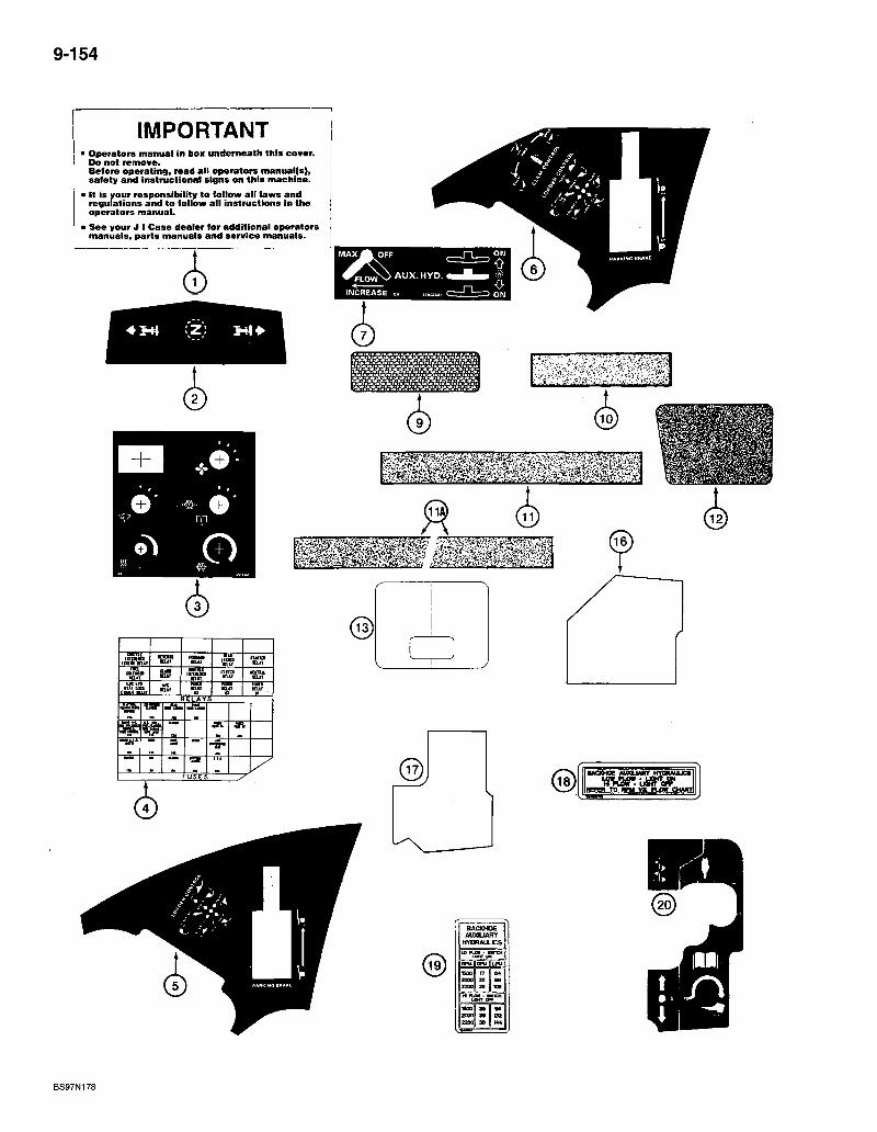
9-154
IMPORTANT > Operators manual in box underneath this cover.
Do not remove. Before operating, read all operators manual(s), safety and instructional signs on this machine.
• It is your responsibility to follow all laws and regulations and to follow all instructions In the operators manual.
I See your J I C a s e dealer for additional operators manuals, parts manuals and service manuals.
> > L O w N > A U X . H Y D .
INCREASE c. ,„=,. ,
w n i i i i m c c i
ivam m i l K n m • U f 'Eu* mut
i i u i a KUI
I K l m m
t o n u « KUT MUT
a n a mm
KITUl tUif
Ut i l t • i n ua
ttmt HUT IK
• U l M l HUT
U
WEI W i n
E L A Y S Mm
S
"' U S E S
d) ® BACKHOE Auoaunr K Y U W U C S
" p q * TO — •
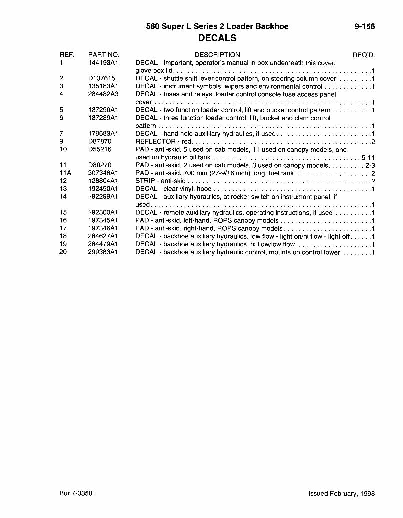
580 Super L Series 2 Loader Bacldioe DECALS
9-155
REF. PART NO. 1 144193A1
2 D137615 3 135183A1 4 284482A3
5 137290A1 6 137289A1
7 179683A1 9 D87870 10 D55216
11 D80270 11A 307348A1 12 128804A1 13 192450A1 14 192299A1
15 192300A1 16 197345A1 17 197346A1 18 284627A1 19 284479A1 20 299383A1
DESCRIPTION REQ'D. DECAL - Important, operator's manual in box underneath this cover, glove box lid 1 DECAL - shuttle shift lever control pattern, on steering column cover 1 DECAL - instrument symbols, wipers and environmental control 1 DECAL - fuses and relays, loader control console fuse access panel cover 1 DECAL - two function loader control, lift and bucket control pattern 1 DECAL - three function loader control, lift, bucket and clam control pattern 1 DECAL - hand held auxilliary hydraulics, if used 1 REFLECTOR - red 2 PAD - anti-skid, 5 used on cab models, 11 used on canopy models, one used on hydraulic oil tank 5-11 PAD - anti-skid, 2 used on cab models, 3 used on canopy models 2-3 PAD - anti-skid, 700 mm (27-9/16 inch) long, fuel tank 2 STRIP - anti-skid 2 DECAL - clear vinyl, hood 1 DECAL - auxiliary hydraulics, at rocker switch on instrument panel, if used 1 DECAL - remote auxiliary hydraulics, operating instructions, if used 1 PAD - anti-skid, left-hand, ROPS canopy models 1 PAD - anti-skid, right-hand, ROPS canopy models 1 DECAL - backhoe auxiliary hydraulics, low flow - light on/hi flow - light off 1 DECAL - backhoe auxiliary hydraulics, hi flow/low flow 1 DECAL - backhoe auxiliary hydraulic control, mounts on control tower 1
Bur 7-3350 Issued February, 1998
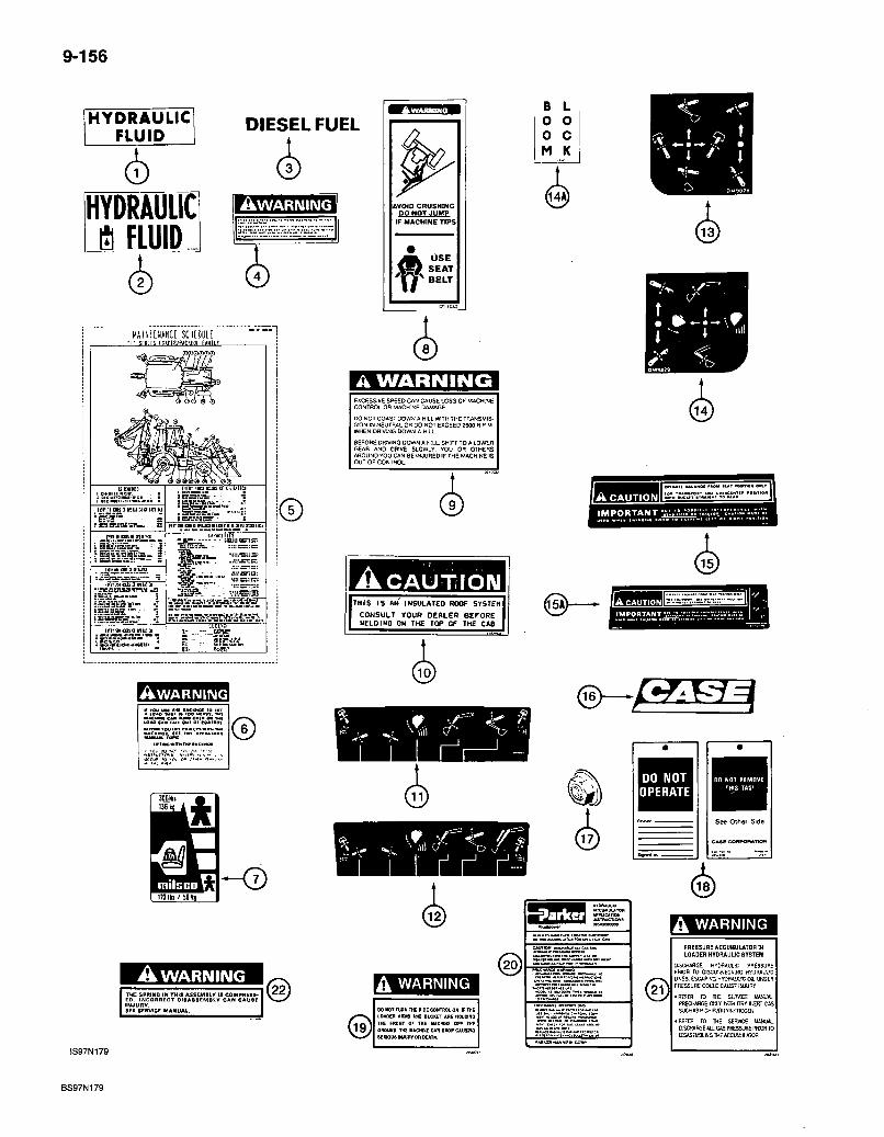
9-156
HYDRAULIC FLUID
D I E S E L FUEL
HYDRAULIC a FlUID^
AWARNING
HAIIIIMH SCHtOOLE
lint M m 9 ffiu'Ki
(nitwcntitnu':!
— " . " " i i i T r " ' —
©
AWARNIIMG
©
IIOIti/50t|
lAVOlO CRUSHING DO MOT JUMP
IF MACHINE TIPS:
U S E ! = # SEAT
BELT I f
A W A R N I N G
DO NOT C O A S T DOWN A HiLL WITH THE TRANSMIS-SiON IN N E U T R A L O R DO NOT EXCEED 2500 H P M WHEN DRIVING DOWN A H I L .
eEFone DRIVING DOWN A H:LL. S H T T TO A L O W E R GEAR AND OfliVE S L O W L Y . Y O U O R OTHERS A R O U N D YOU CAN BE I N J U R E D IF T H E M.ACH NE IS O U T O F C O N T R O L .
A C A U T I I O I V THIS IS AH INSULATED ROOF SYSTEM
CONSULT YOUR DEALER BEFORE UELDINO ON THE TOP OF THE CAB
(Si)
A C A U T I O N
A W A R N I N G THE SPRINO IN THIS ASSEMBLY IS COMPRESSED. INCORRECT DI8ASSEMBLV CAN CAUSE INJURY. SEE SERVICE MANUAL.
JS97N179
DO NOT OPERATE
DO NOT R(MQV£ THIS TAC^
See Other Side
A WARNING PRESSURE ACCUMULATOR IH LOADER HYDRAUUC SYSTEM
DISCHARGE HYDRAialC PRE55LIRE PRIOR TO DlOCCTAECnNG HYDRAJI C LINES. HYDHA'J-JC 0». UMlEfl FRESSUflE COtLD CAUSE r»iJUfiY A WARNING
REFER ID IHL SLHVCE WAVJAL PRECHARGE OflY VVTIH DRi liERT GAS SUCH AS H:5H FUH;IY KITROGEN K) HOT TURN THE R'DE COHTROL ON, V THE
LOADcn Ataa mo SUCKET ARE HOLDINO tm FROHT Of THE UACWHE OFf THE GUUNO. TH£ lUCHIVE CM DROP CAU3H0 lenous iHJURY on DEATH.
REFER TO THE SERVJCE MANUAL DISCHARGE AU GAS PRESSURE PRDR TO D:SASEIi«.KGTHEACaJMUUTOa
BS97N179
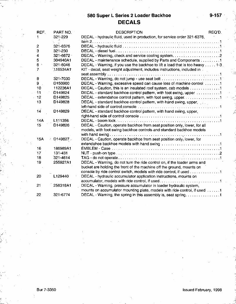
580 Super L Series 2 Loader Bacldioe DECALS
9-157
REF. PART NO 1 321-229
2 321-6376 3 321-230 4 321-6672 5 304940A1 6 321-6046 7 ':1^16534A1
8 321-7030 9 . D150900 10 112236A1 i i D149824 12 D149825 13 D149828
14 D149829
14A L1;11356 15 D149826
15A D149827.
16 186989A1 17 131-431 18 321-4614 19 255927A1
20 LI 29440
21 256318A1
22 321-6774
DESCRIPTION REQ'D. DECAL - hydraulic fluid, used in production, for service order 321 -6376, item 2 DECAL - hydraulic fluid DECAL-diesel fuel DECAL - Warning, check and sen/ice cooling system DECAL - maintenance schedule, supplied by Parts and Components . . . . . . . . . DECAL - Warning, if you use the backhoe to lift a load that is too heavy 1-: KIT - decal, seat weight adjustment, includes instructions, included in seat assembly DECAL - Warning, do not jump - use seat belt DECAL - Warning, excessive speed can cause loss of machine control DECAL - Caution, this is an insulated roof system, cab models DECAL - standard backhoe control pattern, with foot swing, upper DECAL - extendahoe control pattern, with foot swing, upper DECAL - standard backhoe control pattern, with hand swing, upper, left-hand side of control console DECAL - standard backhoe control pattern, with hand swing, upper, right-hand side of control console DECAL - boom lock DECAL - Caution, operate backhoe from seat position only, lower, for all models, with foot swing backhoe controls and standard backhoe models with hand swing DECAL - Caution, operate backhoe from seat position only; lower, for extendahoe backhoe models with hand swing EMBLEM-Case NUT - push-dn type TAG - do not operate DECAL - Warning, do not turn the ride control on, if the loader arms and bucket are holding the front of the machine off the ground, mounts on console by ride control switch, models with ride control, if used DECAL - hydraulic accumulator application instructions, mounts on accumulator, models with ride control, if used DECAL - Warning, pressure accumulator in loader hydraulic system, mounts on accumulator mounting plate, models with ride control, if used DECAL - Warning, the spring in this assembly is, seat spring
Bur 7-3350 Issued February, 1998

580 Super L Series 2 Loader Backhoe
NUMERICAL INDEX
10-1
P A R T N O . P A G E R E F . P A R T N O . P A G E R E F . P A R T N O . P A G E R E F .
A10454 4-5 44 A33509 9-59 29 A77467 2-47 11 A13240 8-63 25 A38208 5-17 5 A77468 2-47 11 A14141 8-3 8 A38208 5-19 7 A77469 2-47 11 A141451 9-77 . 24 A38261 5-19 3 , A77472 2-43 11 A15672 6-23 23 A38261 5-19 6 A77473 2-43 12 A156873 6-5 6 A41264 4-37 9 A77474 2-43 11 A165395 9-131 2 A41264 4-39 5 A77475 2-43 12 A165860 3-5 A41852 3-17 14 A77476 2-43 11 A166057 4-11 2 A42465 2-9 3 A77477 2-43 12 A166057 4-11 17 A42561 9-125 11 A77478 2-43 11 A167037 9-149 8 A45007 4-27 5 A77479 2-43 12 A170241 2-3 2 A45054 9-107 A77490 2-31 A170241 2-5 9 A45093 4-27 15 A77505 2-39 6A A170309 2-15 4 A46948 4-3 2 A77512 3-17 26 A170467 2-11 4 A46950 4-5 39 A77673 2-31 A171099 2-3 15 A47123 4-27 18 A77673 2-41 48 A171940 2-13 6 A47125 . 4-27 19 A77720 3-17 2 A172116 2-13 7 A47127 4-3 13 A77736 2-33 A177435 3-7 2 A47128 4-3 10 A77775 3-17 13 A178706 6-23 24 A47129 4-5 36 A77782 2-39 6 A180163 9-117 18 A47130 4-5 38 A77783 2-35 2 A184545 , 2-3 30 A47230, 4-5 A77809 2-43 23 A184614 9-145 15 A47232 • 4-3 16 A77810 2-43 26 A186171 9-129 A47233 4-3 17 A77817 2-17 19 A186182 4-7 24 A47234 4-3 18 A77840 2-43 12 A186183 4-7 18 A47235 4-3 19 A77841 . 2-43 12 A186186 4-7 15 A47236. 4-3 20 A77864 2-51 A186193 ^ 4-7 25 A47237 4-5 33 A77870 2-41 46 A186256 i 9-129 1 A47238 4-5 34 A77870 2-49 A187504 4-7 13 A47239 4-5 31 A77887 2-41 A187542 4-43 5 A47240 4-3 A77889 2-43 13 A187575 4-43 11 A47241 4-3 27 A77890 2-43 18 A187714 9-131 1 A47242 4-5 28 AC77752 2-39 A187873 4-7 A47243 4-3 B17575 6-5 A187873 4-9 4 A47244 4-5 35 B17575 6-7 A187899 4-7 -12 A47247 4-5 30 B17575 6-9 A187901 4-7 17 A47249 4-5 .32 B17575 6-13 A187903 4-7 1 A47688 4-27 8 B17575 6-15 A187904 4-7 9 A48041 6-13: 11 B17575 . 6-17 A187906 4-7 2 A48041 6-39 6 B17576 9-81 • 35 A187909 9-129 17 A48041 6-41 2 B93222 5-17 A187911 4-35 2A A49667 9-145 3 BMF28S 4-15 1 A187912 4-35 2 A52216 4-33 13 BMF31E 4-13 1 A187914 4-35 4 A61447 5-17 12 D102964 9-149 A187917 4-7 11 A61448 5-17 11 D103626 5-15 A187923 2-13 10 A61449 5-17 10 D120450 9-49 14 A187965 4-27 A62209 9-11 14 D120450 9-55 7 A187990 4-17 11 A65544 5.-3 5 D120561 4-19 19 A1,87990 • 7-7 , 3 2 A66759 5-17 1 D121047 9-11 22 A188028 7-13 23 A77310 7-7 14 D121152 4-29 6 A i89154 2-13 1 A77313 4-21 19 D121152 4-37 A189284 9-145 6 A77314 4-21 18 D121194 9-13 6 A191114 4-27 A77405 2-41 44 D121385 8-59 29. A20058 .6-53 - 2 A77405 2-43 11 D121608 7-13 12 A20058 6-53 2 A77406 2-41 45 D123347 9-151 4 A23870 4-43 1 A77406 2-43 12 D123655 5-15 7 A27602 5-15 28 A77416 2-21 D123684 5-15 6 A28230 5-15 34 A77424 2-41 30 D123684 6-3 i o A30013 8-3 16 A77429 2-39 17 D123806 5-15 16 A30881 9-9 11 A77429 ^ 2-41 34 D123865 5-15 29 A30881 9-29 15 A77465 2-41 43 D124528 7-7 ,19 A30881 9:33 5 A77465 2-47 11 D124529 7-7 13 A30881 9-35 26 A77466 2-47 11 D124530 7-7 23
Bur 7-3350 Issued February, 1998
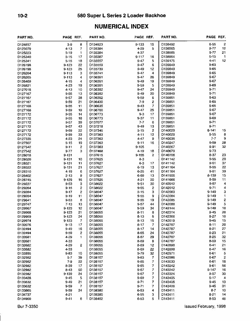
10-2 580 Super L Series 2 Loader Backhoe
NUMERICAL INDEX
P A R T N O . P A G E R E F . P A R T N O . P A G E R E F . P A R T N O . P A G E R E F .
D124857 3-9 8 D134923 9-133 15 D138492 6-55 2 D125079 4-13 7 D135384 4-29 5 D138565 9-77 12 D125223 5-19 1 D135384 4-37 D138565 9-77 21 D125340 5-15 17 D135387 9-117 16 D138954 5-15 1 D125341 5-15 18 D135557 9-47 5 D139175 4-41 12 D126198 9-123 22 D135559 9-47 6 D139849 9-63 D126198 9-123 25 D135739 9-49 12 D139849 9-65 D126204 9-113 3 D135741 9-47 4 D139849 9-65 D126205 9-113 4 D136391 9-47 26 D139849 9-67 D126409 4-15 4 D136391 9-49 19 D139849 9-67 D126821 4-23 19 D136391 9-59 5 D139849 9-69 D127018 4-13 10 D136392 9-47 24 D139849 9-71 D127167 9-55 13 D136392 9-49 20 D139849 9-71 D127167 9-57 38 D136392 9-59 6 D139851 9-63 D127167 9-59 21 D136430 7-9 2 D139851 9-65 D127168 9-55 11 D136635 9-43 7 D139851 9-65 D127168 9-59 19 D136700 9-47 25 D139851 9-67 D127172 9-55 14 D136773 9-3 17 D139851 9-67 D127172 9-55 18 D136773 9-37 11 D139851 9-69 D127172 9-57 39 D137077 7-7 6 D139851 9-71 D127172 9-57 43 D137218 9-49 13 D139851 9-71 D127172 9-59 22 D137345 5-15 2 D140029 8-141 15 D127172 9-59 33 D137363 4-11 12 D140029 9-55 8 D127335 4-23 24 D137363 4-47 9 D140035 7-7 9 D127507 5-15 19 D137363 9-11 16 D140247 9-59 28 D127542 9-11 2 D137363 9-105 D140267 9-91 32 D127542 9-77 3 D137468 4-19 18 D140679 9-73 D128018 9-131 D137615 9-155 2 D140706 8-37 23 D128020 9-131 10 D137625 8-3 D141142 9-55 20 D128021 9-131 11 D137627 6-3 17 D141142 9-61 37 D128022 9-131 21 D137627 6-19 13 D141164 9-55 22 D128310 4-19 6 D137627 6-25 41 D141164 9-61 39 D128402 2-13 9 D137627 6-69 13 D141555 8-139 15 D128745 9-129 16 D137820 4-21 20 D141666 9-59 11 D129227 9-53 3 D138022 9-51 30 D142012 9-67 4 D129264 9-15 2 D138022 9-55 2 D142012 9-71 4 D129264 9-17 2 D138047 5-15 3 D142083 9-149 3 D129264 9-19 11 D138047 9-55 9 D142084 9-149 1 D129641 9-53 6 D138047 9-55 19 D142085 9-149 2 D129747 7-13 13 D138047 9-57 44 D142086 9-149 5 D129967 9-123 12 D138047 9-59 34 D142144 9-149 10 D129968 9-123 21 D138055 8-11 8 D142314 9-45 20 D129969 9-123 24 D138055 8-13 6 D142366 8-27 10 D129974 9-123 7 D138055 8-13 15 D142519 9-45 15 D132076 9-13 17 D138055 8-17 7 D142787 8-11 20 D132494 9-49 16 D138055 8-17 14 D142787 8-21 27 D132494 9-59 2 D138055 8-65 24 D142787 8-23 21 D132681 4-29 1 D138055 8-67 29 D142787 8-25 32 D132681 4-33 D138055 8-69 8 D142787 8-59 15 D132682 4-29 2 D138055 8-69 12 D142898 6-41 21 D132682 4-33 D138055 8-69 22 D142898 6-47 16 D132895 9-83 10 D138055 9-79 32 D142971 6-61 5 D132982 5-7 39 D138157 9-63 7 D142986 6-67 2 D132982 7-9 22 D138157 9-65 7 D143033 6-61 18 D132982 8-39 17 D138157 9-65 7 D143242 9-61 56 D132982 8-43 50 D138157 9-67 7 D143242 9-147 16 D132982 9-139 24 D138157 9-67 7 D143324 9-57 30 D133428 9-45 5 D138157 9-69 7 D143405 5-17 4 D133632 9-49 21 D138157 9-71 7 D143406 9-45 13 D133632 9-59 7 D138157 9-71 7 D143406 9-45 31 D133865 9-59 24 D138380 6-53 4 D143411 8-7 10 D134737 4-21 D138380 6-55 3 D143411 8-21 14 D134900 9-41 6 D138492 6-53 5 D143411 8-53 46
Bur 7-3350 Issued February, 1998

580 Super L Series 2 Loader Backhoe
NUMERICAL INDEX
10-3
P A R T N O . P A G E R E F . P A R T N O . P A G E R E F . P A R T N O . P A G E R E F .
D 1 4 3 4 1 2 8 - 3 3 3 1 0 1 4 8 9 4 7 9 - 3 5 2 0 1 5 0 4 9 3 9 - 2 9 2 4 D 1 4 3 4 1 6 9 - 4 1 5 0 1 4 8 9 6 2 3 - 7 6 0 1 5 0 5 0 3 9 - 3 1 4 5 D 1 4 3 4 1 7 9 - 5 3 8 0 1 4 8 9 9 2 9 - 2 9 7 0 1 5 0 6 0 8 9 ^ 5 5 1 5 D 1 4 3 4 1 7 9 - 9 1 2 5 0 1 4 8 9 9 3 9 - 2 9 1 9 0 1 5 0 6 0 8 9 - 5 9 3 0 D 1 4 3 4 1 7 9 - 9 1 3 0 0 1 4 8 9 9 4 9 - 2 9 1 8 0 1 5 0 6 1 9 9 - 5 7 3 4 D 1 4 3 4 1 7 9 - 1 3 9 2 9 0 1 4 9 0 3 3 9 - 4 5 2 5 0 1 5 0 6 3 3 7 - 1 3 1 1 D 1 4 3 4 1 7 9 - 1 4 1 2 0 0 1 4 9 0 7 9 9 - 5 9 1 6 0 1 5 0 7 8 1 8 - 1 2 1 D 1 4 3 4 2 2 8 - 5 3 2 ; 0 1 4 9 2 3 9 9 - 4 7 3 2 0 1 5 0 8 1 0 8 - 1 2 1 D 1 4 3 4 2 2 8 - 4 3 5 4 0 1 4 9 2 6 2 9 - 3 1 4 6 0 1 5 0 8 9 9 9 - 1 5 3 2 1 D 1 4 3 4 2 6 8 - 3 3 2 9 0 1 4 9 2 8 7 9 - 7 3 6 A 0 1 5 0 9 0 0 9 - 1 5 7 9 D 1 4 3 4 2 7 9 - 1 3 9 2 7 0 1 4 9 2 8 7 9 - 9 4 0 1 5 1 0 3 4 9 - 1 3 1 5 D 1 4 3 4 2 7 9 - 1 4 1 , 1 8 0 1 4 9 2 8 7 9 - 3 1 3 7 0 1 5 1 0 6 5 9 - 4 7 2 1 D 1 4 3 4 3 0 8 - 9 1 8 0 1 4 9 2 8 7 9 - 3 3 1 1 0 1 5 1 0 6 9 9 - 7 7 5 D 1 4 3 5 9 1 9 - 5 3 1 4 0 1 4 9 2 8 7 9 - 3 7 3 0 1 5 1 0 7 0 9 - 7 7 6 D 1 4 3 7 1 4 9 - 9 1 9 0 1 4 9 2 8 7 9 - 4 1 1 1 0 1 5 1 0 7 1 9 - 4 9 1 1 D 1 4 3 7 1 5 9 - 9 1 8 0 1 4 9 2 8 8 7 - 1 3 2 0 0 1 5 1 0 7 3 9 - 4 7 7
, 0 1 4 3 7 2 3 9 - 5 3 1 0 0 1 4 9 2 8 8 9 - 3 2 6 0 1 5 1 0 7 4 9 - 4 7 8 % 1 4 3 7 3 5 9 - 5 3 1 7 0 1 4 9 2 8 8 9 - 7 3 6 0 2 5 2 7 9 9 - 4 5 1 0
D 1 4 3 7 9 7 8 - 7 5 0 1 4 9 2 8 8 9 - 2 9 2 3 0 2 5 2 7 9 9 - 4 5 1 4 D 1 4 3 7 9 7 8 - 7 9 0 1 4 9 2 8 8 9 - 3 1 4 8 0 2 5 2 7 9 9 - 5 7 3 1 D 1 4 3 7 9 7 8 - 3 9 1 9 0 1 4 9 2 8 8 9 - 3 7 . 7 0 2 5 2 7 9 9 - 7 3 7 D 1 4 3 7 9 7 8 - 4 3 5 5 0 1 4 9 2 9 5 9 - 3 1 3 4 0 2 6 0 0 2 9 - 4 5 9 D 1 4 3 8 3 0 4 - 1 1 6 0 1 4 9 2 9 5 9 - 3 7 9 0 2 8 6 4 8 9 - 4 5 1 2 D 1 4 4 4 2 3 9 - 4 7 3 5 0 1 4 9 2 9 8 9 - 5 7 3 2 0 3 0 9 3 3 9 - 6 3 1 2 D 1 4 4 5 9 2 9 - 5 3 . 4 0 1 4 9 7 2 5 6 - 5 2 0 3 0 9 3 3 9 - 6 5 1 2 p i 4 5 0 6 0 s 9 - 6 5 4 0 1 4 9 7 2 6 6 - 5 4 D 3 0 9 3 3 9 - 6 5 1 2 D 1 4 5 0 6 1 9 - 6 7 4 0 1 4 9 7 3 7 6 - 9 8 0 3 0 9 3 3 9 - 6 7 1 2 D 1 4 5 0 6 1 9 - 7 1 4 0 1 4 9 7 3 8 6 - 9 6 0 3 0 9 3 3 9 - 6 7 1 2 D 1 4 5 0 6 2 ' 9 - 6 9 4 0 1 4 9 7 3 9 6 - 9 0 3 0 9 3 3 9 - 6 9 1 2 D;I 4 5 3 6 7 2 - 1 3 . 2 0 1 4 9 8 2 4 9 - 1 5 7 1 1 0 3 0 9 3 3 9 - 7 1 1 2 D 1 4 6 0 3 5 8 - 2 1 2 4 0 1 4 9 8 2 5 9 - 1 5 7 1 2 0 3 0 9 3 3 9 - 7 1 1 2 D 1 4 6 0 3 5 9 - 8 3 . 1 1 0 1 4 9 8 2 6 9 - 1 5 7 1 5 0 3 1 1 4 0 9 - 1 9 2 D 1 4 6 2 8 8 9 - 5 5 2 6 0 1 4 9 8 2 7 9 - 1 5 7 „ 1 5 A 0 3 4 0 3 3 8 - 4 5 2
' D l 4 6 2 8 8 9 - 6 1 4 9 0 1 4 9 8 2 8 9 - 1 5 7 1 3 0 3 4 6 6 6 9 - 2 9 1 6 D 1 4 6 3 3 5 4 - 2 7 1 1 0 1 4 9 8 2 9 9 - 1 5 7 1 4 0 3 5 0 0 9 6 - 2 3 3 2 D 1 4 6 4 2 0 • 9 - 6 5 3 0 1 4 9 8 6 0 6 - 1 9 0 3 6 1 7 9 9 - 8 9 8 D 1 4 6 4 2 0 9 - 6 5 3 0 1 4 9 8 6 0 6 - 6 9 0 3 6 1 7 9 9 - 1 2 5 1 7 D 1 4 6 4 2 0 9 - 6 7 3 0 1 4 9 8 6 6 9 - 2 5 9 0 3 6 2 6 4 2 - 9 1 1 D.I 4 6 4 2 0 9 - 6 7 3 0 1 4 9 8 6 7 9 - 2 5 1 0 D 3 6 5 0 5 5 - 1 5 1 5 D 1 4 6 4 2 0 9 - 6 9 3 0 1 4 9 8 6 8 9 - 2 5 1 2 0 3 6 6 6 9 9 - 1 2 1 1 5 D 1 4 6 4 2 1 9 - 6 5 2 0 1 5 0 0 3 2 9 - 4 1 1 3 0 3 7 4 9 5 9 - 6 5 1 1 0 1 4 6 4 2 1 9 - 6 5 2 0 1 5 0 0 5 3 8 - 5 9 3 0 3 7 4 9 5 9 - 6 5 1 1 0 1 4 6 4 2 1 9 - 6 7 2 0 1 5 0 0 5 4 8 - 5 9 2 0 3 7 4 9 5 9 - 6 7 1 1 0 1 4 6 4 2 1 9 - 6 7 2 0 1 5 0 0 8 0 9 - 5 5 1 7 0 3 7 4 9 5 9 - 6 7 1 1 0 1 4 6 4 2 1 9 - 6 9 2 0 1 5 0 0 8 0 9 - 5 9 3 2 0 3 7 4 9 5 9 - 6 9 1 1 0 1 4 6 5 8 8 9 - 6 5 1 0 1 5 0 0 9 9 8 - 2 1 2 5 0 3 7 4 9 5 9 - 7 1 1 1 0 1 4 7 1 6 6 4 - 1 9 , 1 7 0 1 5 0 1 2 1 9 - 5 5 1 0 0 3 7 4 9 5 9 - 7 1 1 1 0 1 4 7 2 4 7 9 - 6 5 1 - 0 1 5 0 1 2 1 9 - 5 9 - 1 7 0 3 7 4 9 5 - 9 - 7 3 2 0 1 4 7 2 4 9 9 - 6 5 4 0 1 5 0 1 2 2 9 - 5 5 1 6 0 3 7 6 1 4 9 - 5 7 2 9 0 1 4 7 3 8 3 4 - 1 1 1 1 0 1 5 0 1 2 2 9 - 5 7 4 1 0 3 8 4 3 5 8 - 9 2 3 0 1 4 7 3 8 3 4 - 1 1 1 4 0 1 5 0 1 2 2 ' 9 - 5 9 3 1 0 3 8 6 4 8 8 - 1 9 2 0 0 1 4 7 3 8 3 4 - 1 1 3 3 0 1 5 0 1 5 5 5 - 1 5 2 0 D 3 8 6 4 8 8 - 3 7 2 6 0 1 4 7 3 8 3 4 - 1 7 2 0 1 5 0 3 4 8 9 - 6 7 1 0 3 8 8 5 8 8 - 1 4 1 1 2 0 1 4 7 3 8 3 9 - 1 2 7 1 2 0 1 5 0 3 6 4 9 - 6 7 . 1 0 3 8 9 0 7 9 - 4 5 3 0 1 4 7 3 8 3 9 - 1 4 5 2 7 0 1 5 0 3 6 5 9 - 6 9 1 • 0 3 9 0 9 3 . 9 - 6 3 5 0 1 4 7 3 8 3 9 - 1 4 7 8 0 1 5 0 3 7 7 9 - 1 0 3 1 2 . 0 3 9 0 9 3 9 - 6 5 5 0 1 4 7 4 0 9 9 - 6 3 4 0 1 5 0 3 7 7 9 - 1 0 3 2 0 0 3 9 0 9 3 9 - 6 5 5 0 1 4 7 4 1 0 9 - 6 3 3 0 1 5 0 3 9 1 9 - 1 0 3 1 5 0 3 9 0 9 3 9 - 6 7 5 0 1 4 7 4 1 1 9 - 6 3 2 0 1 5 0 3 9 1 9 - 1 0 3 • 2 3 0 3 9 0 9 3 9 - 6 7 5 D 1 4 7 4 1 8 9 - 6 3 • 1 0 1 5 0 3 9 7 9 - 2 9 9 i 0 3 9 0 9 3 9 - 6 9 5 0 1 4 7 7 7 3 8 - 5 9 , 2 6 0 1 5 0 4 3 4 9 - 2 9 1 3 D 3 9 0 9 3 9 - 7 1 5 0 1 4 8 1 0 8 4 - 1 7 1 0 0 1 5 0 4 3 5 9 - 2 9 1 2 0 3 9 0 9 3 . 9 - 7 1 5 0 1 . 4 8 1 0 8 7 - 7 , 3 1 . 0 1 5 0 4 8 6 9 - 2 9 1 7 0 3 9 1 1 8 9 - 3 5 1 1
Bur 7-3350 Issued February, 1998
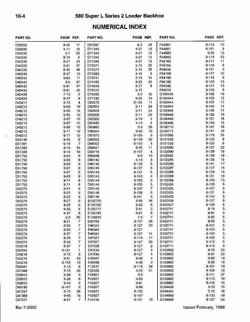
10-4 580 Super L Series 2 Loader Backhoe
NUMERICAL INDEX
P A R T N O . P A G E R E F . P A R T N O . P A G E R E F . P A R T N O . P A G E R E F .
D39256 9-45 17 D67297 8-3 29 F44881 9-119 10 D39696 4-11 19 D71342 4-27 12 F44881 9-121 9 D40236 5-7 25 D71343 4-27 13 F44883 9-93 10 D40236 8-19 6 D71344 4-27 14 F44883 9-119 23 D40236 8-21 23 D71346 4-27 16 F45165 9-117 11 D40236 8-31 37 D72371 5-15 32 F45165 9-119 6 D40236 8-35 48 D72372 5-15 35 F64046 9-121 3 D40236 8-37 13 D73383 4-15 5 F64198 9-117 10 D40243 9-63 11 D73741 2-13 14 F64198 9-119 8 D40442 3-5 37 D74182 8-53 45 F64198 9-123 15 D40442 9-81 37 D74949 5-17 8 F64342 9-117 13 D40442 9-81 42 D75103 5-17 F64519 9-133 8 D42458 7-13 2 D75465 3-3 12 G100440 8-135 16 D42833 8-47 6 D77182 8-25 10 G100444 8-129 15 D43417 9-73 4 D80270 9-155 11 G100444 8-131 17 D48212 9-63 10 D82804 5-11 26 G100444 8-143 14 D48212 9-65 10 D82805 5-11 24 G100448 8-135 17 D48212 9-65 10 D82806 5-11 22 G100449 8-129 16 D48212 9-67 10 D83306 9-73 3 G100449 8-131 18 D48212 9-67 10 D83485 4-13 2 G100449 8-143 15 D48212 9-69 10 D83885 3-3 28 G100710 8-141 18 D48212 9-71 10 D86664 9-53 15 G100711 8-141 19 D48212 9-71 10 D87870 9-155 9 G101066 8-119 32 D50146 9-45 6 D88052 9-139 32 G101533 8-133 6 D51391 9-19 7 D88052 9-143 5 G101533 8-135 6 D51392 9-19 15 D88427 9-45 11 G102090 8-137 22 D51393 9-19 19 D93716 9-147 4 G102090 8-139 19 D51750 9-63 8 D95096 9-9 13 G102092 8-139 18 D51750 9-65 8 D95142 5-13 8 G102285 8-135 15 D51750 9-65 8 D95142 8-129 5 G102286 8-141 17 D51750 9-67 8 D95143 8-127 5 G102287 8-127 14 D51750 9-67 8 D95143 8-131 5 G102288 8-129 14 D51750 9-69 8 D95143 8-143 4 G102288 8-131 16 D51750 9-71 8 D95144 8-133 5 G102288 8-143 13 D51750 9-71 8 D95144 8-135 5 G102424 8-129 6 D52275 8-21 6 D95145 8-137 7 G102425 8-127 6 D52275 8-23 6 D95146 8-139 5 G102425 8-131 6 D52275 8-25 6 D95146 8-141 5 G102425 8-143 5 D52275 8-27 6 E l 35750 6-59 18 G102426 8-137 8 D52275 8-29 6 E l 35762 6-63 8 G102427 8-139 6 D52275 8-33 6 E l 35777 6-61 3 G102711 8-79 5 D52275 8-37 6 E l 35785 6-61 8 G102711 8-81 5 D52276 2-3 25 E135810 7-5 7 G102711 8-85 5 D52276 8-21 7 E43769 9-127 28 G102711 8-99 5 D52276 8-23 7 E46524 9-127 23 G102711 8-101 5 D52276 8-25 7 E46560 9-127 G102711 8-103 5 D52276 8-27 7 E46561 9-127 11 G102711 8-105 5 D52276 8-29 7 E47027 9-115 17 G102711 8-109 5 D52276 8-33 7 E47027 9-147 29 G102711 8-113 5 D52276 8-37 7 E47238 9-127 2 G102711 8-115 5 D52564 9-151 1 E47239 9-127 3 G103862 8-79 22 D54218 9-73 5 E47240 9-127 4 G103862 8-81 25 D55216 9-81 43 E49497 9-39 4 G103862 8-85 19 D55216 9-155 10 E49498 9-39 3 G103862 8-99 15 D55561 4-13 8 F13537 8-119 38 G103862 8-101 19 D57486 5-15 25 F22426 4-25 21 G103862 8-105 19 D59912 9-29 4 F42827 3-5 G103862 8-111 37 D59912 9-35 6 F42827 4-25 G103862 8-113 15 D59912 9-43 2 F42827 9-81 G103862 8-115 15 D60180 9-147 2 F42827 9-89 G104439 5-13 15 D61297 5-15 36 F42827 9-125 G104454 5-13 16 D61368 9-45 16 F42827 9-147 G104989 8-133 18 D67251 8-57 7 F44748 9-121 19 G104989 8-137 24
Bur 7-3350 Issued February, 1998
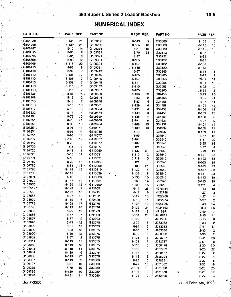
580 Super L Series 2 Loader Backhoe
NUMERICAL INDEX
10-5
P A R T N O . P A G E R E F . P A R T N O . P A G E R E F . P A R T N O . P A G E R E F .
G104989 8-141 21 G109298 8-143 9 G33080 8-109 10 G104990 8-139 21 G109299 8-135 10 G33080 8-113 10 G105187 5-13 14 G109384 8-81 •15 G33080 8-115 10 G106395 8-81 ,8 ' G109391 8-79 23 G33112 8-97 4 G106396 8-81 9 G109391 8-87 G33122 8-81 G106398 8-81 12 G109391 8-105 G33122 8-85 G106409 8-115 29 G109391 8-107 G33122 8-103 G106410 8-85 9 G109391 . 8 - 1 1 5 G33122 8-113 G106410 8-99 7 G109449 8-87 G33965 8-73 11 G106410 8-101 7 G109449 8-105 G33965 8-75 12 G106410 8-105 7 G109449 8-107 G33965 •'8-89 11 G1064,10 8-109 7 G109449 8-111 G33965 . 8-91 12 G106410 8-113 7 G109449 8-115 G33965 8-93 12 G106410 . 8-115 7 G109627 8-103 G33965 .8 -95 12 G106425' • 8-81 • 14 : G109630 8-103 23 G34458 8-79 2 5 ' G106808 5-13 2 G109644 8-83 2 G34458 8-85 21 G106810 5-13 7 G109646 8-83 4 G34458 8-97 11 G106813 5-13 18 G109881 8-129 4 G34458 8-101 13 ,G106817 5-13 6 G109884 8-131 4 .G34458 8-105 13 G106832 5-13 4 G109884 8-143 3 G34458 8-109 13 G107251 8-73 10 G109899 8-135 4 G34463 8-103 6 G107251 8-75 -11 G109908 8-141 6 G34937 8-97 9 G107251 8-89 10 G109964 8-109 15 G34937 8-101 11 G 1 0 7 2 5 1 , 8-91 11 G109971 8-109 18 G34937 8-105 11 G107251 . 8-93 11 G110045 5-13 G34937 8-109 11 G107251 8-95 11 G110077 8-99 G35540 8-77 16 G107277 8-143 12 G110077 8-101 G35540 8-81 20 G107447 8-79 9 G110077 8-107 G35540 8-85 14 G107720 5-5 17 G110077 8-121 G35540 8-87 4 G107720 5-13 1 G110269 8-137 21 G35540 8-99 19 G107720 5-15 11 G110391 8-119 3 G35540 8-101 23 G107721 5-13 G110391 8-119 5 G35540 8-103 13 G107780 8-79 16 G110467 8-121 G35540 8-103 19 G107780 8-81 16 G110468 8-103 21 G35540 8-105 23 G107780 8-119 19 G110519 8-133 4 G35540 , 8-107 36 G107786 8-111 G110529 8-133-- 15 G35540 8-11.1 23 G107921 5-13 9 G110530 8-133 16 G35540 8-113 19 G107970 8-137 14 G110531 8-133 . 14 G35540 8-115 19 G107970 8-139 12 • G110569 8-139 16 . G35540 8-121 4 G1085j12 - 8-129 3 G13609 5-11 25 H275784 2-13 13 (3108518 8-129 13 G15215 5-17 9 H422758 4-27 3 G108556 8-77 12 G32122 8-127 10 H422766 4-27 4 G108630 8-119 6 G32129 5-13 11 H422774 4-27 2 G108723 8-109 17 G32176 8-133 10 H433285 9-49 24 G108723 8-119 26 G32176 8-135 24 H434163 8-3 26 G108805 8-75 13 G32303 8-127 18 H71514 9-49 7 G108866 8-77 7 " G32303 8-131 20 J280911 2-35 11 G108867 8-77 9 G32303 8-135 19 J282406 3-15 8 G108870 8-73 12 G33075 8-79 6 J283333 2-33 2 G108899 8-91 13 G33075 8-81 6 J283333 2-41 47 G108899 8-93 13 G33075 8-85 6 J283336 2-33 2 G108900- 8-89 12 G33075 8-99 6 J283338 2-33 2 G108902 8-97 2 G33075 8-101 6 J283767 2-41 23 G108911 8-119 15 G33075 8-103 . 7 J283767 2-51 8 G108912 8-119 13 G33075 8-105 6 J330478 2-39 17D G108913 8-119 11 G33075 8-109 6 J527759 2-25 22 G108914 8-119 9 G33075 8-113 6 J528177 2-27 2 G108956 8-119 37 G33075 8-115 6 J528204 2-27 4 G108957 8-119 39 G33080 8-85 10 J528221 2-27 5 G109127 8-81 10 G33080 8-99 10 J531582 2-25 19 G109295 8-79 10 G33080 8-101 10 J531598 2-25 20 G109298 8-129 .10 G33080 8-103 9 J531670 2-25 17 G109298 8-131 11 G33080 8-105 10 J532195 2-27 7
Bur7-3350 Issued February, 1998
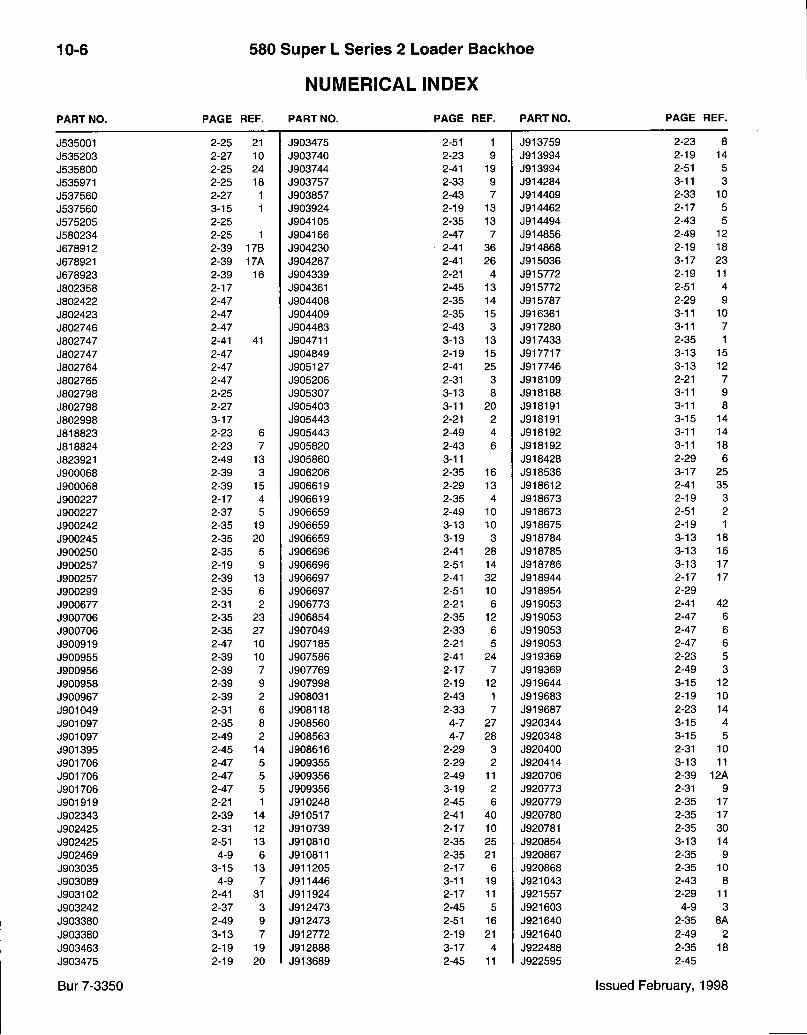
10-6 580 Super L Series 2 Loader Backhoe
NUMERICAL INDEX
P A R T N O . P A G E R E F . P A R T N O . P A G E R E F . P A R T N O . P A G E R E F .
J535001 2-25 21 J903475 2-51 1 J913759 2-23 8 J535203 2-27 10 J903740 2-23 9 J913994 2-19 14 J535800 2-25 24 J903744 2-41 19 J913994 2-51 5 J535971 2-25 18 J903757 2-33 9 J914284 3-11 3 J537560 2-27 1 J903857 2-43 7 J914409 2-33 10 J537560 3-15 1 J903924 2-19 13 J914462 2-17 5 J575205 2-25 J904105 2-35 13 J914494 2-43 5 J580234 2-25 1 J904166 2-47 7 J914856 2-49 12 J678912 2-39 17B J904230 2-41 36 J914868 2-19 18 J678921 2-39 17A J904287 2-41 26 J915036 3-17 23 J678923 2-39 16 J904339 2-21 4 J915772 2-19 11 J802358 2-17 J904361 2-45 13 J915772 2-51 4 J802422 2-47 J904408 2-35 14 J915787 2-29 9 J802423 2-47 J904409 2-35 15 J916361 3-11 10 J802746 2-47 J904483 2-43 3 J917280 3-11 7 J802747 2-41 41 J904711 3-13 13 J917433 2-35 1 J802747 2-47 J904849 2-19 15 J917717 3-13 15 J802764 2-47 J905127 2-41 25 J917746 3-13 12 J802765 2-47 J905206 2-31 3 J918109 2-21 7 J802798 2-25 J905307 3-13 8 J918188 3-11 9 J802798 2-27 J905403 3-11 20 J918191 3-11 8 J802998 3-17 J905443 2-21 2 J918191 3-15 14 J818823 2-23 6 J905443 2-49 4 J918192 3-11 14 J818824 2-23 7 J905820 2-43 6 J918192 3-11 18 J823921 2-49 13 J905860 3-11 J918428 2-29 6 J900068 2-39 3 J906206 2-35 16 J918536 3-17 25 J900068 2-39 15 J906619 2-29 13 J918612 2-41 35 J900227 2-17 4 J906619 2-35 4 J918673 2-19 3 J900227 2-37 5 J906659 2-49 10 J918673 2-51 2 J900242 2-35 19 J906659 3-13 10 J918675 2-19 1 J900245 2-35 20 J906659 3-19 3 J918784 3-13 18 J900250 2-35 5 J906696 2-41 28 J918785 3-13 16 J900257 2-19 9 J906696 2-51 14 J918786 3-13 17 J900257 2-39 13 J906697 2-41 32 J918944 2-17 17 J900299 2-35 6 J906697 2-51 10 J918954 2-29 J900677 2-31 2 J906773 2-21 6 J919053 2-41 42 J900706 2-35 23 J906854 2-35 12 J919053 2-47 6 J900706 2-35 27 J907049 2-33 6 J919053 2-47 6 J900919 2-47 10 J907185 2-21 5 J919053 2-47 6 J900955 2-39 10 J907586 2-41 24 J919369 2-23 5 J900956 2-39 7 J907769 2-17 7 J919369 2-49 3 J900958 2-39 9 J907998 2-19 12 J919644 3-15 12 J900967 2-39 2 J908031 2-43 1 J919683 2-19 10 J901049 2-31 6 J908118 2-33 7 J919687 2-23 14 J901097 2-35 8 J908560 4-7 27 J920344 3-15 4 J901097 2-49 2 J908563 4-7 28 J920348 3-15 5 J901395 2-45 14 J908616 2-29 3 J920400 2-31 10 J901706 2-47 5 J909355 2-29 2 J920414 3-13 11 J901706 2-47 5 J909356 2-49 11 J920706 2-39 12A J901706 2-47 5 J909356 3-19 2 J920773 2-31 9 J901919 2-21 1 J910248 2-45 6 J920779 2-35 17 J902343 2-39 14 J910517 2-41 40 J920780 2-35 17 J902425 2-31 12 J910739 2-17 10 J920781 2-35 30 J902425 2-51 13 J910810 2-35 25 J920854 3-13 14 J902469 4-9 6 J910811 2-35 21 J920867 2-35 9 J903035 3-15 13 J911205 2-17 6 J920868 2-35 10 J903089 4-9 7 J911446 3-11 19 J921043 2-43 8 J903102 2-41 31 J911924 2-17 11 J921557 2-29 11 J903242 2-37 3 J912473 2-45 5 J921603 4-9 3 J903380 2-49 9 J912473 2-51 16 J921640 2-35 8A J903380 3-13 7 J912772 2-19 21 J921640 2-49 2 J903463 2-19 19 J912888 3-17 4 J922488 2-35 18 J903475 2-19 20 J913689 2-45 11 J922595 2-45
Bur 7-3350 Issued February, 1998
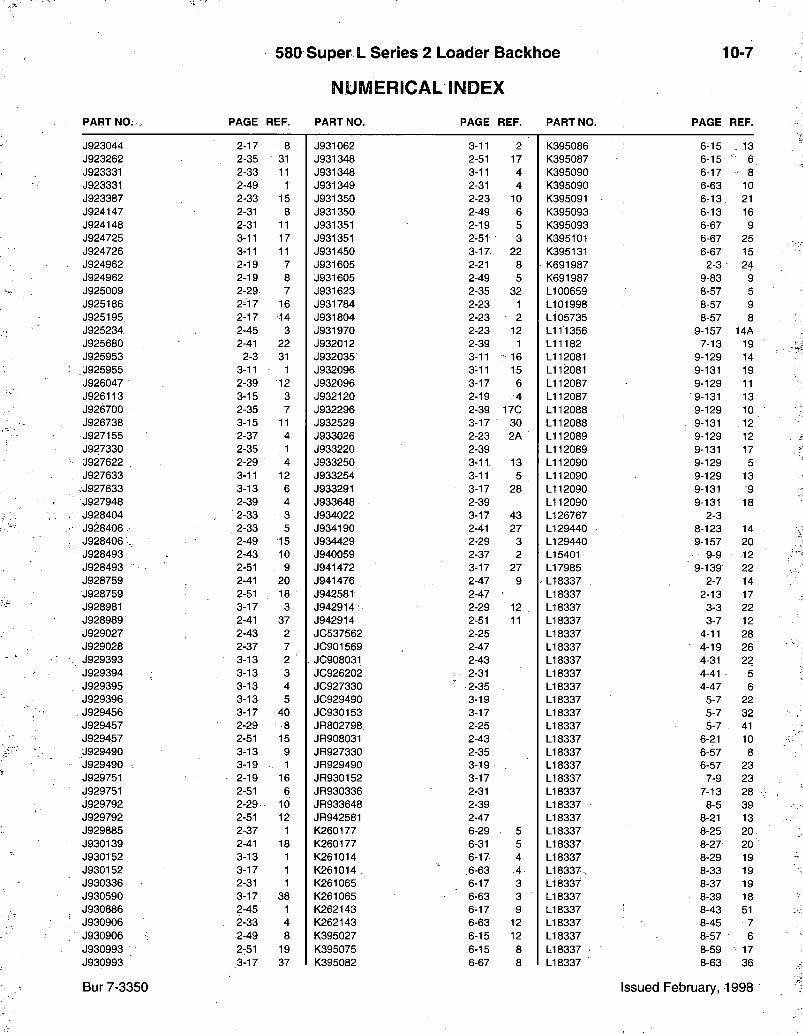
580 Super L Series 2 Loader Baclthoe
NUMERICAL INDEX
10-7
P A R T N O . . P A G E R E F . P A R T N O . P A G E R E F . P A R T N O . P A G E R E F .
J923044 2-17 8 J931062 3-11 2 K395086 6-15 , 13 J923262 2-35 31 J931348 2-51 17 K395087 6-15 • 6 J923331 2-33 11 J931348 3-11 4 K395090 6-17 8 J923331 2-49 1 J931349 2-31 4 K395090 6-63 10 J923387 2-33 15 J931350 2-23 10 K395091 6-13 21 J924147 2-31 8 J931350 2-49 6 K395093 6-13 16 J924148 2-31 11 J931351 2-19 5 K395093 6-67 9 J924725 3-11 17 J931351 2-51 3 K395101 6-67 25 J924726 3-11 11 J931450 3-17- 22 K395131 6-67 15 J924962 2-19 7 J931605 2-21 8 K691987 2-3. 24 J924962 2-19 8 J931605 2-49 5 K691987 9-83 9 J925009 2-29 7 J931623 2-35 32 LI 00659 8-57 5 J925186 2-17 16 J931784 2-23 1 L I 01998 8-57 9 J925195. 2-17 14 J931804 2-23 2 L105735 8-57 8 J925234 2-45 3 J931970 2-23 12 L111356 9-157 14A J925680 2-41 22 J932012 2-39 1 L11182 7-13 19 J925953 2-3 31 J932035 3-11 ? 16 L112081 9-129 14 J925955 3-11 1 J932096 3-11 15 L112081 9-131 19 J926047 2-39 12 J932096 3-17 6 L112087 9-129 11 J926113 3-15 3 J932120 2-19 4 L112087 9-131 13 J926700 2-35 7 J932296 2-39 170 L112088 9-129 10 J926738 3-15 11 J932529 3-17 30 L112088 9-131 12 J927155 2-37 4 J933026 2-23 2A L112089 9-129 12 J927330 2-35 , 1 J933220 2-39 L112089 9-131 17 J927622 2-29 4 J933250 3-11 13 L112090 9-129 5 J927633 3-11 12 J933254 3-11 5 L112090 9-129 13
,J927633 3-13 6 J933291 3-17 28 L112090 9-131 9 ;J927948 2-39 4 J933648 2-39 L112090 9-131 18 J928404 2-33 3 J934022 3-17 43 L I 26767 2-3 J928406. . 2-33 5 J934190 2-41 27 L I 29440 8-123 14 J928406 ., 2-49 15 J934429 2-29 3 L I 29440 9-157 20 J928493 2-43 10 j940059 2-37 2 L I 5401 9-9 12 J928493 2-51 9 J941472 3-17 27 L I 7985 9-139 22 J928759 2-41 20 J941476 2-47 9 L I 8337 2-7 14 J928759 2-51 18 J942581 2-47 LI 8337 2-13 17 J928981 3-17 3 J942914; 2-29 12 L I 8337 3-3 22 J928989 2-41 37 J942914 2-51 11 LI 8337 3-7 12 J929027 2-43 2 JG537562 2-25 LI 8337 4-11 28 J929028 2-37 7 JC901569 2-47 LI 8337 4-19 26 J929393 3-13 2 JC908031 2-43 LI 8337 4-31 22 J929394 3-13 3 JG926202 : 2-31 LI 8337 4-41 5 J929395 3-13 4 JC927330 2-35 LI 8337 4-47 6 J929396 3-13 5 JC929490 3-19 LI 8337 5-7 22 J929456 3-17 40 JC930153 3-17 LI 8337 5-7 32 J929457 2-29 8 JR802798 2-25 LI 8337 5-7 41 J929457 2-51 15 JR908031 2-43 LI 8337 6-21 10 J929490 3-13 9 JR927330 2-35. LI 8337 6-57 8 'J929490 . 3-19 - 1 JR929490 3-19 LI 8337 6-57 23 J929751 2-19 16 JR930152 3-17 LI 8337 7-9 23 J929751 2-51 6 JR930336 2-31 LI 8337 7-13 28 J929792 2-29 10 JR933648 2-39 LI 8337 8-5 39 J929792 2-51 12 JR942581 2-47 LI 8337 8-21 13 J929885 2-37 1 K260177 6-29 5 LI 8337 8-25 20 J930139 2-41 18 K260177 6-31 5 LI 8337 8-27 20 J930152 3-13 1 K261014 6-17 4 LI 8337 8-29 19 J930152 3-17 1 K261014 . .6-63 4 LI 8 3 3 7 , 8-33 19 J930336 2-31 1 K261065 6-17 3 LI 8337 8-37 19 J930590 3-17 38 K261065 6-63 3 LI 8337 8-39 18 J930886 2-45 1 K262143 6-17 9 LI 8337 8-43 51 J930906 2-33 4 K262143 6-63 12 LI 8337 8-45 7 J930906 2-49 8 K395027 6-15 12 LI 8337 8-57 6 J930993 2-51 19 K395075 6-15 8 LI 8337 8-59 • 17 J930993 3-17 37 K395082 6-67 8 LI 8337 8-63 36
Bur 7-3350 Issued February, 1998
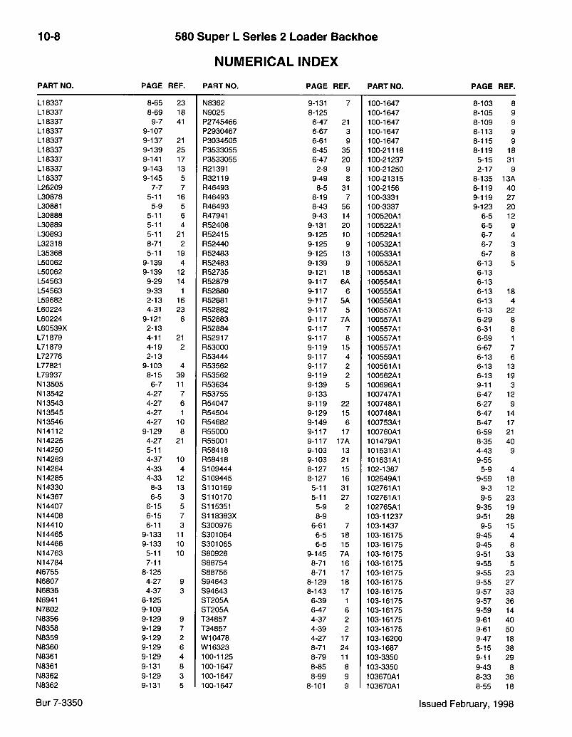
10-8 580 Super L Series 2 Loader Baclthoe
NUMERICAL INDEX
P A R T N O . P A G E R E F . P A R T N O . P A G E R E F . P A R T N O . P A G E R E F .
LI 8337 8-65 23 N8362 9-131 7 100-1647 8-103 8 LI 8337 8-69 18 N9025 8-125 100-1647 8-105 9 LI 8337 9-7 41 P2745466 6-47 21 100-1647 8-109 9 LI 8337 9-107 P2930467 6-67 3 100-1647 8-113 9 L I 8337 9-137 21 P3034505 6-61 9 100-1647 8-115 9 L I 8337 9-139 25 P3533055 6-45 35 100-21118 8-119 18 L I 8337 9-141 17 P3533055 6-47 20 100-21237 5-15 31 L I 8337 9-143 13 R21391 2-9 9 100-21250 2-17 9 L I 8337 9-145 5 R32119 9-49 8 100-21315 8-135 13A L26209 7-7 7 R46493 8-5 31 100-2156 8-119 40 L30878 5-11 16 R46493 8-19 7 100-3331 9-119 27 L30881 5-9 5 R46493 8-43 56 100-3337 9-123 20 L30888 5-11 6 R47941 9-43 14 100520A1 6-5 12 L30889 5-11 4 R52408 9-131 20 100522A1 6-5 9 L30893 5-11 21 R52415 9-125 10 100529A1 6-7 4 L32318 8-71 2 R52440 9-125 9 100532A1 6-7 3 L35368 5-11 19 R52483 9-125 13 100533A1 6-7 8 L50062 9-139 4 R52483 9-139 9 100552A1 6-13 5 L50062 9-139 12 R52735 9-121 18 100553A1 6-13 L54563 9-29 14 R52879 9-117 6A 100554A1 6-13 L54563 9-33 1 R52880 9-117 6 100555A1 6-13 18 L59682 2-13 16 R52881 9-117 5A 100556A1 6-13 4 L60224 4-31 23 R52882 9-117 5 100557A1 6-13 22 L60224 9-121 8 R52883 9-117 7A 100557A1 6-29 8 L60539X 2-13 R52884 9-117 7 100557A1 6-31 8 L71879 4-11 21 R52917 9-117 8 100557A1 6-59 1 L71879 4-19 2 R53000 9-119 15 100557A1 6-67 7 L72776 2-13 R53444 9-117 4 100559A1 6-13 6 L77821 9-103 4 R53562 9-117 2 100561A1 6-13 13 L79937 8-15 39 R53562 9-119 2 100562A1 6-13 19 N13505 6-7 11 R53634 9-139 5 100696A1 9-11 3 N13542 4-27 7 R53755 9-133 100747A1 6-47 12 N13543 4-27 6 R54047 9-119 22 100748A1 6-27 9 N13545 4-27 1 R54504 9-129 15 100748A1 6-47 14 N13546 4-27 10 R54682 9-149 6 100753A1 6-47 17 N14112 9-129 8 R55000 9-117 17 100760A1 6-59 21 N14225 4-27 21 R55001 9-117 17A 101479A1 8-35 40 N14250 5-11 R58418 9-103 13 101531A1 4-43 9 N14283 4-37 10 R58418 9-103 21 101631A1 9-55 N14284 4-33 4 S I 09444 8-127 15 102-1387 5-9 4 N14285 4-33 12 S I 09445 8-127 16 102649A1 9-59 18 N14330 8-3 13 S110169 5-11 31 102761A1 9-3 12 N14367 6-5 3 S110170 5-11 27 102761A1 9-5 23 N14407 6-15 5 8115351 5-9 2 102765A1 9-35 19 N14408 6-15 7 S118383X 8-9 103-11237 9-51 28 N14410 6-11 3 S300976 6-61 7 103-1437 9-5 15 N14465 9-133 11 8301064 6-5 18 103-16175 9-45 4 N14466 9-133 10 8301065 6-5 15 103-16175 9-45 8 N14763 5-11 10 S80928 9-145 7A 103-16175 9-51 33 N14784 7-11 888754 8-71 16 103-16175 9-55 5 N6755 8-125 888756 8-71 17 103-16175 9-55 23 N6807 4-27 9 894643 8-129 18 103-16175 9-55 27 N6836 4-37 3 894643 8-143 17 103-16175 9-57 33 N6941 8-125 8T205A 6-39 1 103-16175 9-57 36 N7802 9-109 8T205A 6-47 6 103-16175 9-59 14 N8356 9-129 9 T34857 4-37 2 103-16175 9-61 40 N8358 9-129 7 T34857 4-39 2 103-16175 9-61 50 N8359 9-129 2 W10478 4-27 17 103-16200 9-47 18 N8360 9-129 6 W16323 8-71 24 103-1687 5-15 38 N8361 9-129 4 100-1125 8-79 11 103-3350 9-11 29 N8361 9-131 8 100-1647 8-85 8 103-3350 9-43 8 N8362 9-129 3 100-1647 8-99 9 103670A1 8-33 36 N8362 9-131 5 100-1647 8-101 9 103670A1 8-55 18
Bur 7-3350 Issued February, 1998
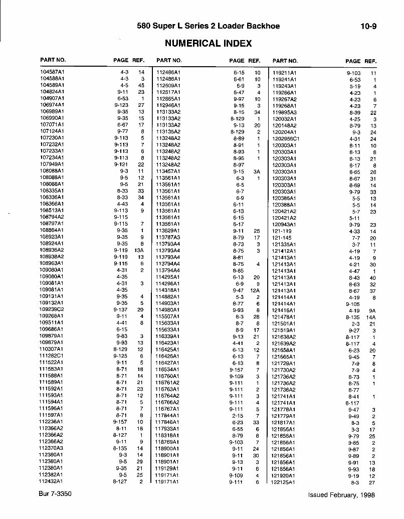
580 Super L Series 2 Loader Backhoe
NUMERICAL INDEX
10-9
P A R T N O . P A G E R E F . P A R T N O . P A G E R E F . P A R T N O . P A G E R E F .
104587A1 4-3 14 112486A1 6-15 10 119211A1 9-103 11 104588A1 4-3 3 112486A1 6-61 10 119241A1 6-53 1 104589A1 4-5 45 112509A1 6-9 3 119243A1 5-19 4 104824A1 9-11 23 112517A1 6-47 4 119266A1 4-23 1 104907A1 6-53 1 112865A1 9-97 10 119267A2 4-23 6 106974A1 9-123 27 112946A1 9-15 3 119268A1 4-23 7 106989A1 9-35 13 113133A2 8-15 34 119895A3 8-39 22 106990A1 9-35 15 113133A2 8-129 1 120032A1 4-25 3 107071A1 6-67 17 113133A2 9-13 20 120148A2 8-79 13 107124A1 9-77 8 113135A2 8-129 2 120204A1 9-3 24 107230A1 9-113 5 113248A2 8-89 1 1202956C1 4-31 24 107232A1 9-113 7 113248A2 8-91 1 120303A1 8-11 10 107233A1 9-113 6 113248A2 8-93 1 120303A1 8-13 8 107234A1 9-113 8 113248A2 8-95 1 120303A1 8-13 21 107949A1 9-121 22 113248A2 8-97 120303A1 8-17 8 108088A1 9-3 11 113457A1 9-15 3A 120303A1 8-65 26 108088A1 9-5 12 113561A1 6-3 1 120303A1 8-67 31 108088A1 9-5 21 113561A1 6-5 120303A1 8-69 14 108335A1 8-33 33 113561A1 6-7 120303A1 9-79 33 108336A1 8-33 34 113561A1 6-9 120386A1 5-5 13 108366A1 4-43 4 113561A1 6-11 120388A1 5-5 14 108513A1 9-113 9 113561A1 6-13 120421A2 5-7 23 108794A2 9-115 113561A1 6-15 120421A2 5-11 108797A1 9-115 7 113561A1 6-17 120943A1 9-79 23 108864A1 9-35 1 113629A1 9-11 25 121-119 4-33 14 108923A1 9-35 9 113787A3 8-79 17 121-145 7-7 20 108924A1 9-35 8 113793A4 8-73 3 121335A1 3-7 11 108936A2 9-119 13A 113793A4 8-75 3 121412A1 4-19 7 108938A2 9-119 13 113793A4 8-81 121413A1 4-19 9 108963A1 9-115 6 113794A4 8-75 4 121413A1 4-21 30 109080A1 4-31 2 113794A4 8-85 121413A1 4-47 1 109080A1 4-35 114295A1 6-13 20 121413A1 8-43 40 109081A1 4-31 3 114296A1 6-9 9 121413A1 8-63 32 109081A1 4-35 114318A1 9-47 12A 121413A1 8-67 37 109131A1 9-35 4 114882A1 5-3 2 121414A1 4-19 8 109132A1 9-35 5 114903A1 8-77 6 121414A1 9-105 109239C2 9-137 20 114980A1 9-93 8 121416A1 4-19 9A 109268A1 9-11 4 115507A1 8-3 28 121478A1 8-135 14A 109511A1 4-41 8 115633A1 8-7 8 121501A1 2-3 21 109686A1 6-15 115633A1 8-9 17 121519A1 9-27 3 109879A1 9-83 3 116339A1 9-13 21 121638A2 8-117 1 109879A1 9-93 13 116423A1 4-41 2 121639A2 8-117 4 110307A1 8-129 12 116425A1 6-13 12 121658A1 6-23 20 111282C1 9-125 6 116426A1 6-13 7 121665A1 9-45 7 111522A1 9-11 5 116427A1 6-13 8 121729A1 7-9 8 111583A1 8-71 18 116534A1 9-157 7 121730A2 7-9 4 111588A1 8-71 14 116760A1 9-109 3 121736A2 8-73 1 111589A1 8-71 21 116761A2 9-111 1 121736A2 8-75 1 111592A1 8-71 23 116763A1 9-111 2 121736A2 8-77 111593A1 8-71 12 116764A2 9-111 3 121741A1 8-41 1 111594A1 8-71 5 116766A2 9-111 4 121741A1 8-117 111596A1 8-71 7 116767A1 9-111 5 121778A1 9-47 3 111597A1 8-71 8 117844A1 2-15 7 121779A1 9-49 2 112236A1 9-157 10 117846A1 6-23 33 121817A1 8-3 5 112366A2 8-11 18 117933A1 6-55 6 121856A1 3-3 17 112366A2 8-127 1 118318A1 8-79 8 121856A1 9-79 25 112366A2 9-11 9 118769A1 9-103 7 121856A1 9-85 2 112370A3 8-135 14 118900A1 9-11 24 121856A1 9-87 2 112380A1 9-3 14 118901A1 9-11 30 121856A1 9-89 2 112380A1 9-5 29 118901A1 9-13 3 121856A1 9-91 13 112380A1 9-35 21 119129A1 9-11 6 121856A1 9-93 18 112382A1 9-5 25 119171A1 9-109 4 121920A1 9-19 12 112432A1 8-127 2 119171A1 9-111 6 122125A1 8-3 27
Bur 7-3350 Issued February, 1998
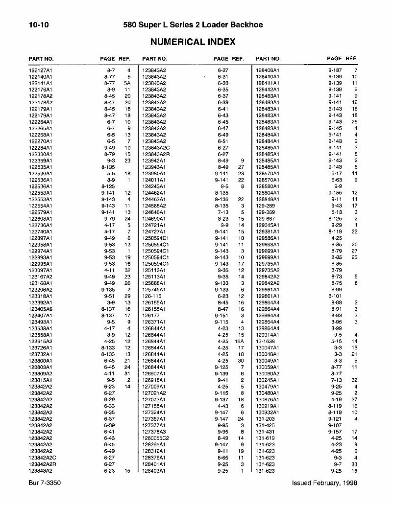
10-10 580 Super L Series 2 Loader Backhoe
NUMERICAL INDEX
P A R T N O . P A G E R E F . P A R T N O . P A G E R E F . P A R T N O . P A G E R E F .
122127A1 8-7 4 123843A2 6-27 128406A1 9-137 7 122140A1 8-77 5 123843A2 6-31 128410A1 9-139 10 122141A1 8-77 5A 123843A2 6-33 128411A1 9-139 11 122176A1 8-9 11 123843A2 6-35 128412A1 9-139 2 122178A2 8-45 20 123843A2 6-37 128483A1 9-141 9 122178A2 8-47 20 123843A2 6-39 128483A1 9-141 16 122179A1 8-45 18 123843A2 6-41 128483A1 9-143 16 122179A1 8-47 18 123843A2 6-43 128483A1 9-143 18 122264A1 6-7 10 123843A2 6-45 128483A1 9-143 25 122265A1 6-7 9 123843A2 6-47 128483A1 9-145 4 122268A1 6-5 13 123843A2 6-49 128484A1 9-141 4 122270A1 6-5 7 123843A2 6-51 128484A1 9-143 9 122284A1 9-49 10 123843A2C 6-27 128485A1 9-141 3 122330A1 8-79 15 123843A2R 6-27 128485A1 9-141 8 122359A1 9-3 23 123942A1 8-49 9 128485A1 9-143 2 122535A1 8-135 123943A1 8-49 27 128485A1 9-143 8 122536A1 5-5 18 123980A1 9-141 23 128570A1 6-17 11 122536A1 8-9 1 124011A1 9-141 22 128570A1 6-63 9 122536A1 8-125 124243A1 9-5 8 128580A1 9-9 122553A1 9-141 12 124462A1 8-135 128804A1 9-155 12 122553A1 9-143 4 124463A1 8-135 22 128818A1 9-11 11 122554A1 9-143 11 124568A2 8-135 3 129-289 9-43 17 122579A1 9-141 13 124646A1 7-13 5 129-369 5-13 3 122603A1 9-79 24 124690A1 8-23 15 129-667 8-125 2 122736A1 4-17 5 124721A1 9-9 14 129015A1 9-29 1 122740A1 4-17 7 124727A1 9-141 15 129391A1 8-119 22 122897A1 9-49 6 1250594C1 9-141 10 129586A1 4-25 122958A1 9-53 13 1250594C1 9-141 11 129698A1 8-85 20 122974A1 9-53 1 1250594C1 9-143 3 129699A1 8-79 27 122993A1 9-53 19 1250594C1 9-143 10 129699A1 8-85 23 122995A1 9-53 16 1250594C1 9-143 17 129735A1 8-85 123097A1 4-11 32 125113A1 9-35 12 129735A2 8-79 123167A2 9-49 23 125113A1 9-35 14 129842A2 8-73 5 123168A1 9-49 26 125688A1 9-133 3 129842A2 8-75 6 123206A2 9-135 2 125749A1 9-133 6 129861A1 8-99 123318A1 9-51 29 126-116 6-23 12 129861A1 8-101 123392A1 3-9 13 126155A1 8-45 16 129864A4 8-89 2 123405A6 8-137 16 126155A1 8-47 16 129864A4 8-91 3 123407A1 8-137 17 126177 9-151 3 129864A4 8-93 3 123493A1 9-5 9 126371A1 9-115 4 129864A4 8-95 3 123538A1 4-17 4 126844A1 4-23 13 129864A4 8-99 123558A1 3-9 12 126844A1 4-25 15 129914A1 9-5 4 123615A2 4-25 12 126844A1 4-25 15A 13-1638 5-15 14 123726A1 8-133 12 126844A1 4-25 17 130047A1 3-3 15 123732A1 8-133 13 126844A1 4-25 18 130048A1 3-3 21 123800A1 6-45 21 126844A1 4-25 30 130049A1 3-3 5 123803A1 6-45 24 126844A1 9-125 7 130059A1 8-77 11 123809A2 4-11 31 126907A1 9-139 6 130060A2 8-77 123815A1 9-5 2 126918A1 9-41 2 130245A1 7-13 32 123842A2 6-23 14 127009A1 4-25 5 130479A1 9-25 4 123842A2 6-27 127021A2 9-115 8 130480A1 9-25 2 123842A2 6-29 127073A1 9-137 18 130876A1 4-19 27 123842A2 6-33 127158A1 4-43 6 130919A1 8-119 16 123842A2 6-35 127324A1 9-147 6 130932A1 8-119 10 123842A2 6-37 127367A1 9-147 24 131-203 9-121 4 123842A2 6-39 127377A1 9-95 3 131-425 9-107 123842A2 6-41 127378A3 9-95 8 131-431 9-157 17 123842A2 6-43 1280055C2 8-49 14 131-619 4-25 14 123842A2 6-45 128265A1 9-147 9 131-623 4-23 9 123842A2 6-49 128312A1 9-11 19 131-623 4-25 6 123842A2C 6-27 128376A1 6-65 11 131-623 9-3 4 123842A2R 6-27 128401A1 9-25 3 131-623 9-7 33 123843A2 6-23 15 128403A1 9-25 1 131-623 9-25 15
Bur 7-3350 Issued February, 1998

580 Super L Series 2 Loader Bacl(hoe
NUMERICAL INDEX
10-11
P A R T N O . P A G E R E F . P A R T N O . P A G E R E F . P A R T N O . P A G E R E F .
131-861 9-133 7 • 133604A1 8-29 26 134610601 8-103 131039A1 9-137 8 133604A1 8-33 26 134610702 8-89 131041A1 9-137 10 133605A1 8-25 36 134610702 8-91 131042A1 9-137 11 133605A1 8-27 30 134610702 8-93 131084A1 2-3 8 133605A1 8-29 22 134610702 8-95 131124A1 9-139 1 133605A1 8-33 22 134610802 8-73 131127A2 9-141 1 133615A1 9-3 2 134610802 8-75 131196A1 8-119 133617A1 9-5 18 134612803 8-117 12 13i197A1 8-117 3 133711A1 4-21 12 134612903 8-117 10 131197A1 8-119 133713A1 4-21 13 134617501 8-79 19 131586A1 8-3 3 133715A1 4-21 15 134617501 8-81 22 131600A1 8-45 10 133716A1 4-21 14 134617501 8-85 16 131676A1 7-9 14 133989A1 9-5 13 134617501 8-99 12 131691A1 4-17 6 1340287C1 9-125 12 134617501 8-101 16 131794A1 4-31 19 1340287C1 9-141 14 134617501 8-105 16 131794A1 4-39 134031901 4-25 31 134617501 8-111 34 131795A1 4-31 17 134034501 9-119 11 134617501 8-1-13 12 131795A1 4-39 134034501 9-121 10 134617501 8-115 12 131796A1 4-31 15 134047801 8-49 13 134618901 8-19 2 131796A1 4-39 134049202 9-137 1 134618901 8-131 1 131797A1 4-31 14 134079801 8-131 15 134619001 8-19 1 131797A1 4-39 1340969C2 8-37 22 134619001 8-131 1 131973A1 9-133 2 134096902 8-143 1 134619101 8-131 2 131973A1 9-137 12 134096902 9-59 .25 134619201 8-131 2 131974A1 9-137 9 134097001 8-143 2 134619501 8-131 13 131975A2 9-99 I B 134125A1 9-137 • 6 134621902 8-81 131977A2 9-115 4A 134167A1 9-47 20 134621902 8-85 132004A2 8-73 4 134197501 8-119 17 134621903 8-79 132004A2 8-75 5 134205401 5-3 1 • 134621903 8-99 132004A2 8-83 134365803 5-11 134621903 8-101 132024A1 9-129 17A 134370801 8-79 20 134621903 8-105 132025A1 9-129 134370801 8-81 23 134621903 8-111 132133A1 9-99 8 134370801 8-85 17 134621903 8-113 132134A1 9-99 1 134370801 8-99 13 134621903 8-115 132212A1 8-25 17 134370801 8-101 17 134622102 8-97 132212A1 8-27 17 134370801 8-105 17 134622102 8-101 132212A1 8-29 16 134370801 8-111 35 134622102 8-105 132212A1 8-33 16 134370801 8-113 13 134622102 8-109 132215A1 2-3 12 134370801 8-115 13 134622201 8-109 132217A1 2-3 14 134377701 8-81 21 134631202 8-119 41 132218A1 2-3 13 134377701 8-85 - 15 ,134826401 3-3 18 132661A1 9-3 5 134379102 8-119 134844A1 9-17 3 132716A1 9-61 52 134393802 9-137 2 134905801 6-17 5 132842A1 9-61 54 134402501 9-105 134905901 6-17 6 132844A1 9-61 53 134402601 9-105 134905901 6-63 • 5 132862A1 9-105 134423201 9-123 18 135161A1 8-127 13 132866A1 9-105 134437A1 9-55 135183A1 9-125 2 132872A1 9-107 134437A1 9-59 -• 135183A1 9-155 3 132873A1 9-7 39 134548803 4-11 4 135185A1 9-125 1 132929A1 5-5 12 134601802 8-137 18 135247A1 9-47 16 132930A1 8-25 38 134602301 8-107 135248A1 9-47 9 132930A1 8-27 32 134610101 8-137 3 135249A1 9-47 10 132930A1 8-29 24 134610502 8-79 135324A1 9-145 2 132930A1 8-33 24 134610502 8-81 135512A3 9-105 132931A1 3-9 2 134610502 8^85 135867A1 5-11 12 132931A1 9-3 25 134610502 8-99 135869A1 5-11 17 133024A1 9-97 2 134610502 8-101 136-154 9-121 26 133025A1 9-97 1 134610502 8-105 136-54 4-43 14 133041A1 4-19 134610502 8-107 136008A1 1 8-7 17 133083A1 . 8-127 12 134610502 8-109 136008A1 ' 8-43 52 1331102C2 9-133 4 1346105C2 8-111 136036A1 9-125 3 133421A1 9-107 134610502 8-113 136226A1 8-13 26 133422A1 9-107 134610502 8-115 136261A1 9-29 i r
Bur 7-3350 lissued February, 1998
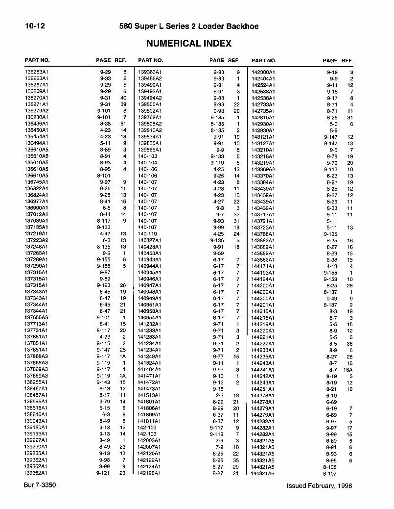
10-12 580 Super L Series 2 Loader Backlioe
NUMERICAL INDEX
P A R T N O . P A G E R E F . P A R T N O . P A G E R E F . P A R T N O . P A G E R E F .
136263A1 9-29 8 139363A1 9-93 9 142300A1 9-19 3 136263A1 9-33 2 139486A2 9-93 1 142404A1 9-9 2 136267A1 9-29 5 139490A1 9-91 4 142524A1 9-11 12 136269A1 9-29 6 139492A1 9-91 3 142538A1 9-15 7 136270A1 9-31 40 139494A2 9-83 1 142538A1 9-17 8 136271A1 9-31 39 139500A1 9-93 22 142733A1 8-71 4 136279A2 9-101 3 139502A1 9-93 20 142735A1 8-71 11 136280A1 9-101 7 139768A1 9-135 1 142815A1 8-25 31 136436A1 8-35 51 139808A2 8-135 1 142930A1 5-3 6 136450A1 4-23 14 139810A2 8-135 2 142930A1 5-9 136454A1 4-23 18 139834A1 9-91 19 143121A1 9-147 12 136494A1 5-11 9 139835A1 9-91 15 143127A1 9-147 13 136610A5 8-89 3 139865A1 9-9 8 143210A1 9-5 7 13661 OAS 8-91 4 140-103 9-133 5 143218A1 9-79 19 136610A5 8-93 4 140-104 9-119 5 143219A1 9-79 20 136610A5 8-95 4 140-106 4-25 13 143369A2 9-113 10 136610A5 8-101 140-106 9-25 14 143370A1 6-23 13 136745A1 9-97 9 140-107 4-23 8 143384A1 8-21 19 136822A1 9-25 11 140-107 4-23 11 143439A1 8-25 12 136824A1 9-25 13 140-107 4-23 15 143439A1 8-27 12 136977A1 8-41 16 140-107 4-27 22 143439A1 8-29 11 136990A1 6-5 8 140-107 9-3 3 143439A1 8-33 11 137012A1 8-41 14 140-107 9-7 32 143717A1 5-11 11 137039A1 8-117 9 140-107 9-93 31 143721A1 5-11 137135A1 9-133 140-107 9-99 19 143723A1 5-11 13 137219A1 4-47 13 140-119 4-25 24 143786A1 9-105 137223A2 6-3 13 140327A1 9-135 5 143882A1 8-25 16 137248A1 8-135 13 140428A1 9-91 18 143882A1 8-27 16 137283A1 9-9 1 140453A1 9-59 143882A1 8-29 15 137289A1 9-155 6 140943A1 6-17 7 143882A1 8-33 15 137290A1 9-155 5 140944A1 6-17 7 144171A1 4-13 4 137315A1 9-87 140945A1 6-17 7 144193A1 9-155 1 137315A1 9-89 140946A1 6-17 7 144194A1 9-153 10 137315A1 9-123 26 140947A1 6-17 7 144200A1 8-25 28 137343A1 8-45 19 140948A1 6-17 7 144200A1 8-137 1 137343A1 8-47 19 140949A1 6-17 7 144200A1 9-49 9 137344A1 8-45 21 140951A1 6-17 7 144201A1 8-137 2 137344A1 8-47 21 140953A1 6-17 7 144215A1 8-3 19 137655A3 9-101 1 140954A1 6-17 7 144216A1 8-7 3 137713A1 8-41 15 141232A1 9-71 1 144219A1 5-5 15 137731A1 9-117 20 141233A1 9-71 3 144220A1 8-9 12 137851A1 4-23 2 141233A1 9-71 3 144221A1 5-5 6 137851A1 9-115 2 141234A1 9-71 2 144227A1 8-5 36 137851A1 9-147 25 141234A1 9-71 2 144233A1 8-9 6 137868A3 9-117 1A 141249A1 9-77 15 144235A1 8-27 28 137868A3 9-119 1 141324A1 9-11 1 144240A1 8-7 16 137869A3 9-117 1 141404A1 9-97 3 144241A1 8-7 16A 137869A3 9-119 1A 141471A1 9-13 1 144242A1 8-19 5 138255A1 9-143 15 141472A1 9-13 2 144243A1 8-19 12 138467A1 8-13 12 141473A1 9-15 144251A1 8-21 10 138467A1 8-17 11 141513A1 2-3 18 144278A1 6-19 138595A1 9-79 14 141801A1 8-29 21 144278A1 6-69 138616A1 5-15 8 141806A1 8-29 20 144279A1 6-19 7 138616A1 6-3 9 141809A1 8-37 11 144279A1 6-69 7 139043A1 8-49 8 141811A1 8-37 12 144282A1 9-97 5 139180A1 9-13 12 142-103 9-117 9 144282A1 9-97 17 139195A1 9-13 14 142-103 9-119 7 144282A1 9-99 15 139227A1 8-49 1 142003A1 7-9 3 144321A5 8-89 5 139230A1 8-49 23 142007A1 7-9 18 144321A5 8-91 6 139235A1 9-13 13 142120A1 8-25 22 144321A5 8-93 6 139362A1 9-93 7 142122A1 8-25 35 144321A5 8-95 6 139362A1 9-99 9 142124A1 8-27 29 144321A5 8-105 139362A1 9-121 23 142126A1 8-27 21 144321A5 8-107
Bur 7-3350 Issued February, 1998
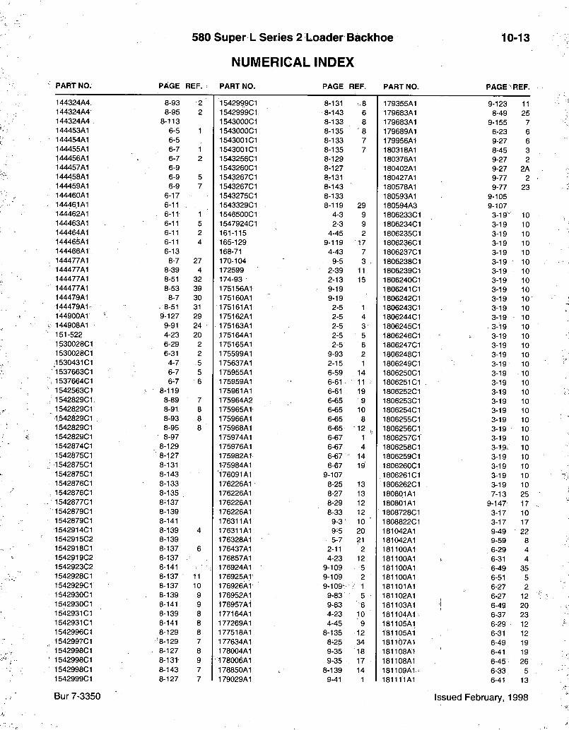
580 Super L Series 2 Loader Backhoe
NUMERICAL INDEX
10-13
P A R T N O . P A G E R E F . P A R T N O . P A G E R E F . P A R T N O . P A G E R E F .
144324A4 8-93 2 1542999C1 8-131 •.8 179355A1 9-123 11 144324A4 8-95 2 1542999C1 •8-143 6 179683A1 8-49 25 144324A4 8-113 1543000C1 8-133 8 179683A1 9-155 7 144453A1 6-5 1 1543000C1 8-135 8 179689A1 6-23 6 144454A1 6-5 1543001 C I 8-133 7 179956A1 9-27 6 144455A1 6-7 1 1543001 C I 8-135 7 180318A1 8-45 3 144456A1 6-7 2 1543256C1 8-129 180376A1 9-27 2 144457A1 6-9 1543260C1 8-127 180402A1 9-27 2A 144458A1 6-9 5 1543267C1 8-131 180427A1 9-77 2 144459A1 6-9 7 1543267C1 8-143 180578A1 9-77 23 144460A1 6-17 1543275C1 8-133 180593A1 9-105 14446.1 A1 6-11 1543329C1 8-119 29 180594A3 9-107 144462A1 . .6-11 1 1546500C1 4-3 9 1806233C1 3-19- 10 144463A1 6-11 5 1547924C1 2-3 9 1806234C1 3-19 10 144464A1 6-11 2 161-115 4-45 2 - 1806235C1 3-19 10 144465A1 6-11 4 165-129 9-119 17 1806236C1 3-19 10 144466A1. 6-13 168-71 4-43 7 1806237C1 3-19 10 144477A1 8-7 27 170-104 9-5 3 . 1806238C1 3-19 10 144477A1 8-39 4 172599 2-39 11 1806239C1 3-19 10 144477A1 8-51 32 174-93 2-13 15 1806240C1 3-19 10 144477A1 8-53 39 175156A1 9-19 1806241C1 3-19 10 144479A1 8-7 30 175160A1 9-19 1806242C1 3-19 10 144479A1 8-51 31 175161A1 2-5 1 1806243C1 3-19 10 144900A1 9-127 29 175162A1 2-5 4 1806244C1 3-19 • 10 144908A1 9-91 24 175163A1 2-5 3 1806245C1 3-19 10 151-522 4-23 20 175164A1 2-5 5 1806246C1 : 3-19 10 1530028C1 6-29 2 175165A1 2-5 6 1806247C1 3-19 10 1530028C1 6-31 2 175599A1 9-93 2 1806248C1 3-19 10 1530431 C I 4-7 .5 175637A1 2-15 1 1806249C1 3-19 10 1537663G1 6-7 5 175955A1 6-59 14 1806250C1 3-19 ' 10 1537664C1 6-7 6 175959A1 6-61 11 1806251 C I 3-19 10 1542563C1 8-119 175961A1 6-61 19 1806252C1 3-19 10 1542829C1. 8-89 7 175964A2 6-65 9 1806253C1 3-19 10 1542829C1 8-91 8 175965A1 6-65 10 1806254C1 3-19 10 •1542829C1 8-93 8 175966A1 6-65 8 1806255C1 3-19 10 1542829C1 8-95 8 175968A1 6-65 •12 1806256C1 3-19 10 1542829C1 8-97 175974A1 6-67 1 1806257G1 3-19 10 1542874C1 8-129 175976A1 6-67 4 1806258C1 3-19.: 10 1542875C1 8-127 175982A1 6-67 14 1806259C1 3-19 10 1542875C1 8-131 175984A1 6-67 19 1806260C1 3-19 10 1542875C1 8-143 176091A1 9-107 1806261 C I 3-19 10 1542876C1 8-133 176226A1 8-25 13 1806262C1 3-19 10 1542876C1 8-135 176226A1 8-27 13 180801A1 7-13 25 1542877C1 8-137 176226A1 8-29 12 180801A1 9-147- 17 1542879C1 8-139 176226A1 8-33 12 1808728C1 3-17 10 1542879C1 8-141 176311A1 9-3 • 10 ' 1808822C1 3-17 17 1542914C1 8-139 4 176311A1 9-5 20 181042A1 9-49 22 1542915C2 8-139 176328A1 5-7 21 181042A1 9-59 8 1542918C1 - 8-137 6 176437A1 2-11 2 181100A1 6-29 4 1542919C2 8-137 176857A1 4-23 12 181100A1 6-31 4 1542923C2 8-141 176924A1 9-109 5 181100A1 6-49 35 1542928C1 8-137 11 176925Ar 9-109 2 l iBIIOOAl 6-51 5 1542929C1 8-137 10 176926A1 9-109- • 'i -1 181101A1 6-27 2 1542930C1 8-139 9 176952A1 9-83 5 ; 181102A1 6-27 12 1542930C1 8-141 9 176957A1 9-83 6 181103A1 1 6-49 20 1542931 C I 8-139 8 177164A1 4-23 10 181104A1. 6-37 23 1542931CI 8-141 8 177269A1 4-45 9 181105A1 6-29 12 1542996C1 8-129 8 177518A1 8-135 12 181105A1 6-31 12 1542997C1 '8-129 7 177634A1 8-25 34 181107A1 6-49 19 1542998C1 8-127 8 178004A1 9-35 18 181108A1 6-41 19 1542998C1 8-131 9 178006A1 9-35 17 181108A1 6-45 26 1542998C1 8-143 7 178850A1 8-139 14 181109A1 6-33 5 1542999C1 8-127 7 179029A1 9-41 1 181111A1 6-41 13
Bur 7-3350 Issued February, 1998
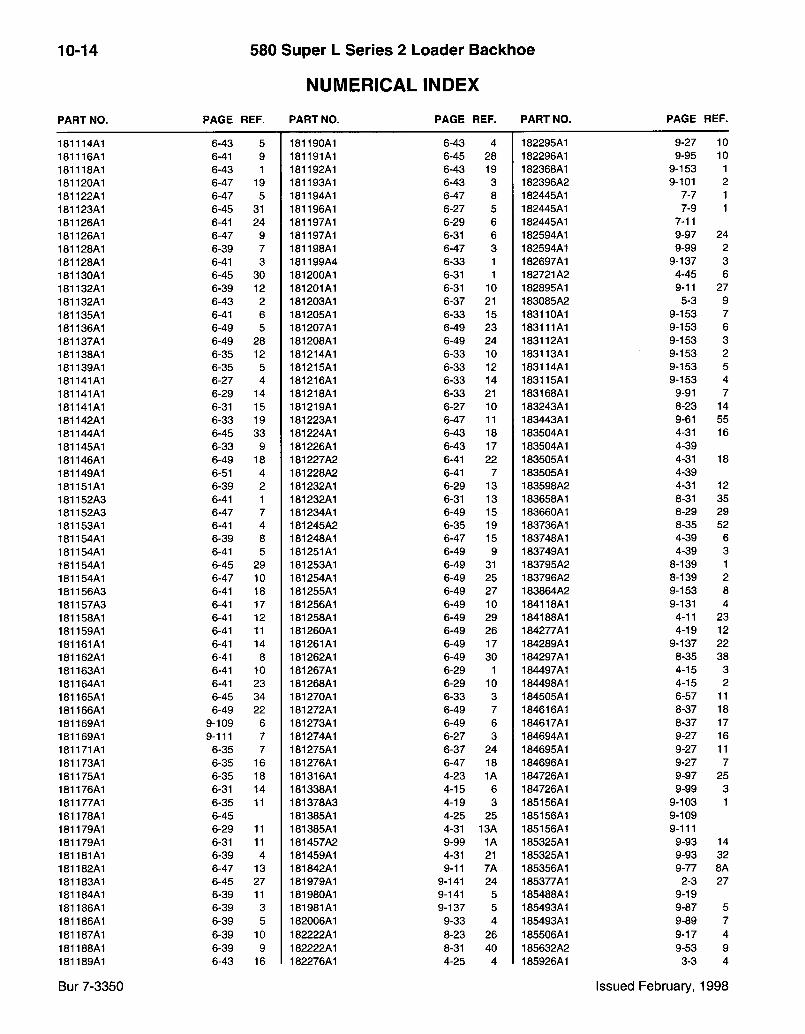
10-14 580 Super L Series 2 Loader Backhoe
NUMERICAL INDEX
P A R T N O . P A G E R E F . P A R T N O . P A G E R E F . P A R T N O . P A G E R E F .
181114A1 6-43 5 181190A1 6-43 4 182295A1 9-27 10 181116A1 6-41 9 181191A1 6-45 28 182296A1 9-95 10 181118A1 6-43 1 181192A1 6-43 19 182368A1 9-153 1 181120A1 6-47 19 181193A1 6-43 3 182396A2 9-101 2 181122A1 6-47 5 181194A1 6-47 8 182445A1 7-7 1 181123A1 6-45 31 181196A1 6-27 5 182445A1 7-9 1 181126A1 6-41 24 181197A1 6-29 6 182445A1 7-11 181126A1 6-47 9 181197A1 6-31 6 182594A1 9-97 24 181128A1 6-39 7 181198A1 6-47 3 182594A1 9-99 2 181128A1 6-41 3 181199A4 6-33 1 182697A1 9-137 3 181130A1 6-45 30 181200A1 6-31 1 182721A2 4-45 6 181132A1 6-39 12 181201A1 6-31 10 182895A1 9-11 27 181132A1 6-43 2 181203A1 6-37 21 183085A2 5-3 9 181135A1 6-41 6 181205A1 6-33 15 183110A1 9-153 7 181136A1 6-49 5 181207A1 6-49 23 183111A1 9-153 6 181137A1 6-49 28 181208A1 6-49 24 183112A1 9-153 3 181138A1 6-35 12 181214A1 6-33 10 183113A1 9-153 2 181139A1 6-35 5 181215A1 6-33 12 183114A1 9-153 5 181141A1 6-27 4 181216A1 6-33 14 183115A1 9-153 4 181141A1 6-29 14 181218A1 6-33 21 183168A1 9-91 7 181141A1 6-31 15 181219A1 6-27 10 183243A1 8-23 14 181142A1 6-33 19 181223A1 6-47 11 183443A1 9-61 55 181144A1 6-45 33 181224A1 6-43 18 183504A1 4-31 16 181145A1 6-33 9 181226A1 6-43 17 183504A1 4-39 181146A1 6-49 18 181227A2 6-41 22 183505A1 4-31 18 181149A1 6-51 4 181228A2 6-41 7 183505A1 4-39 181151A1 6-39 2 181232A1 6-29 13 183598A2 4-31 12 181152A3 6-41 1 181232A1 6-31 13 183658A1 8-31 35 181152A3 6-47 7 181234A1 6-49 15 183660A1 8-29 29 181153A1 6-41 4 181245A2 6-35 19 183736A1 8-35 52 181154A1 6-39 8 181248A1 6-47 15 183748A1 4-39 6 181154A1 6-41 5 181251A1 6-49 9 183749A1 4-39 3 181154A1 6-45 29 181253A1 6-49 31 183795A2 8-139 1 181154A1 6-47 10 181254A1 6-49 25 183796A2 8-139 2 181156A3 6-41 18 181255A1 6-49 27 183864A2 9-153 8 181157A3 6-41 17 181256A1 6-49 10 184118A1 9-131 4 181158A1 6-41 12 181258A1 6-49 29 184188A1 4-11 23 181159A1 6-41 11 181260A1 6-49 26 184277A1 4-19 12 181161A1 6-41 14 181261A1 6-49 17 184289A1 9-137 22 181162A1 6-41 8 181262A1 6-49 30 184297A1 8-35 38 181163A1 6-41 10 181267A1 6-29 1 184497A1 4-15 3 181164A1 6-41 23 181268A1 6-29 10 184498A1 4-15 2 181165A1 6-45 34 181270A1 6-33 3 184505A1 6-57 11 181166A1 6-49 22 181272A1 6-49 7 184616A1 8-37 18 181169A1 9-109 6 181273A1 6-49 6 184617A1 8-37 17 181169A1 9-111 7 181274A1 6-27 3 184694A1 9-27 16 181171A1 6-35 7 181275A1 6-37 24 184695A1 9-27 11 181173A1 6-35 16 181276A1 6-47 18 184696A1 9-27 7 181175A1 6-35 18 181316A1 4-23 1A 184726A1 9-97 25 181176A1 6-31 14 181338A1 4-15 6 184726A1 9-99 3 181177A1 6-35 11 181378A3 4-19 3 185156A1 9-103 1 181178A1 6-45 181385A1 4-25 25 185156A1 9-109 181179A1 6-29 11 181385A1 4-31 13A 185156A1 9-111 181179A1 6-31 11 181457A2 9-99 1A 185325A1 9-93 14 181181A1 6-39 4 181459A1 4-31 21 185325A1 9-93 32 181182A1 6-47 13 181842A1 9-11 7A 185356A1 9-77 8A 181183A1 6-45 27 181979A1 9-141 24 185377A1 2-3 27 181184A1 6-39 11 181980A1 9-141 5 185488A1 9-19 181186A1 6-39 3 181981A1 9-137 5 185493A1 9-87 5 181186A1 6-39 5 182006A1 9-33 4 185493A1 9-89 7 181187A1 6-39 10 182222A1 8-23 26 185506A1 9-17 4 181188A1 6-39 9 182222A1 8-31 40 185632A2 9-53 9 181189A1 6-43 16 182276A1 4-25 4 185926A1 3-3 4
Bur 7-3350 Issued February, 1998
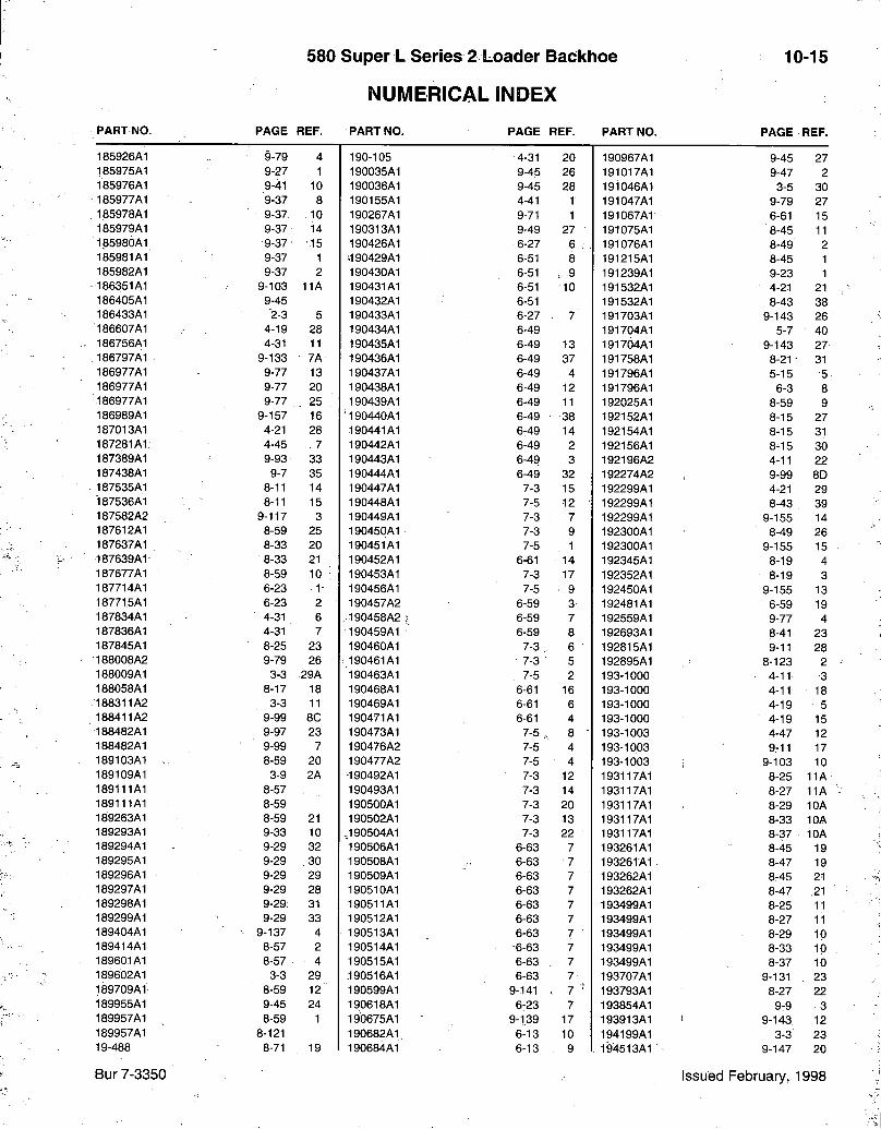
580 Super L Series 2 Loader Backlioe
NUMERICAL INDEX
10-15
P A R T N O . P A G E R E F . P A R T N O . P A G E R E F . P A R T N O . P A G E R E F .
185926A1 9-79 4 190-105 4-31 20 190967A1 9-45 27 185975A1 9-27 1 190035A1 9-45 26 191017A1 9-47 2 185976A1 9-41 10 190036A1 9-45 28 191046A1 3-5 30 185977A1 9-37 8 190155A1 4-41 1 191047A1 9-79 27 1.85978A1 9-37 10 190267A1 9-71 1 191067A1 6-61 15 185979A1 9-37 14 190313A1 9-49 27 191075A1 8-45 11 185980A1 9-37 15 190426A1 6-27 6 :-. 191076A1 8-49 2 185981A1 9-37 1 i190429A1 6-51 8 191215A1 8-45 1 185982A1 9-37 2 190430A1 6-51 .. 9 191239A1 9-23 1 186351A1 9-103 11A 190431A1 6-51 10 191532A1 4-21 21 186405A1 9-45 190432A1 6-51 191532A1 8-43 38 186433A1 "2-3 5 190433A1 6-27 7 191703A1 9-143 26 186607A1 4-19 28 190434A1 6-49 191704A1 5-7 40 186756A1 4-31 11 190435A1 6-49 13 191764A1 9-143 27 186797A1 9-133 7A 190436A1 6-49 37 191758A1 8-21 • 31 186977A1 9-77 13 190437A1 6-49 4 191796A1 5-15 5 186977A1 9-77 20 190438A1 6-49 12 191796A1 6-3 8 186977A1 9-77 25 : 190439A1 6-49 11 192025A1 8-59 9 186989A1 9-157 16 190440A1 6-49 - 38 192152A1 8-15 27 187013A1 4-21 28 190441A1 6-49 14 192154A1 8-15 31 187281A1. 4-45 . 7 190442A1 6-49 2 192156A1 8-15 30 187389A1 9-93 33 190443A1 6-49 3 192196A2 4-11 22 187438A1 9-7 35 190444A1 6-49 32 192274A2 9-99 8D 187535A1 8-11 14 190447A1 7-3 15 192299A1 4-21 29 187536A1 8-11 15 190448A1 7-5 12 • 192299A1 8-43 39 187582A2 9-117 3 190449A1 7-3 7 192299A1 9-155 14 187612A1 8-59 25 190450A1 7-3 9 192300A1 8-49 26 187637A1 8-33 20 190451A1 7-5 1 192300A1 9-155 15 187639A1- 8-33 21 190452A1 6-61 14 192345A1 8-19 4 187677A1 8-59 10 190453A1 7-3 17 192352A1 8-19 3 187714A1 6-23 1- 190456A1 7-5 : 9 192450A1 9-155 13 187715A1 6-23 2 190457A2 6-59 3 192481A1 6-59 19 187834A1 4-31 6 190458A2 6-59 7 192559A1 9-77 4 187836A1 4-31 7 190459A1^ 6-59 8 192693A1 8-41 23 187845A1 8-25 23 190460A1 7-3 6 192815A1 9-11 28 188008A2 9-79 26 190461A1 7-3 5 192895A1 8-123 2 188009A1 3-3 29A 190463A1 7-5 2 193-1000 4-11 3 188058A1 8-17 18 190468A1 6-61 16 193-1000 4-11 18 188311A2 3-3 11 190469A1 6-61 6 193-1000 4-19 5 188411A2 9-99 8C 190471A1 6-61 4 193-1000 4-19 15 188482A1 9-97 23 190473A1 7-5 8 • 193-1003 4-47 12 188482A1 9-99 7 190476A2 7-5 4 193-1003 9-11 17 189103A1 - 8-59 20 190477A2 7-5 4 193-1003 9-103 10 189109A1 3-9 2A •190492A1 7-3 12 193117A1 8-25 11A 189111A1 8-57 190493A1 7-3 14 193117A1 8-27 11A 189111A1 8-59 190500A1 7-3 20 193117A1 8-29 10A 189263A1 8-59 21 190502A1 7-3 13 193117A1 8-33 10A 189293A1 9-33 10 ,190504A1 7-3 22 193117A1 8-37 10A 189294A1 9-29 32 "190506A1 6-63 7 193261A1 8-45 19 189295A1 9-29 . 30 190508A1 6-63 • 7 193261A1 8-47 19 189296A1 9-29 29 190509A1 6-63 7 • 193262A1 8-45 21 189297A1 9-29 28 190510A1 6-63 7 193262A1 8-47 .21 189298A1 9-29 31 190511A1 6-63 7 193499A1 8-25 11 189299A1 9-29 33 190512A1 6-63 7 193499A1 8-27 11 189404A1 9-137 4 190513A1 6-63 7 ' 193499A1 8-29 10 189414A1 8-57 2 190514A1 -6-63 7 193499A1 8-33 10 189601A1 8-57 • 4 190515A1 6-63 7 193499A1 8-37 10 189602A1 3-3 29 ,190516A1 6-63 7 193707A1 9-131 23 189709A1 8-59 12 190599A1 9-141 ,. 7 193793A1 8-27 22 189955A1 9-45 24 190618A1 6-23 7 193854A1 9-9 3 189957A1 8-59 1 19b675A1 9-139 17 193913A1 9-143 12 189957A1 8-121 190682A1 6-13 10 194199A1 3-3 23 19-488 8-71 19 190684A1 6-13 9 . 194513A1 9-147 20
Bur 7-3350 Issued February, 1998
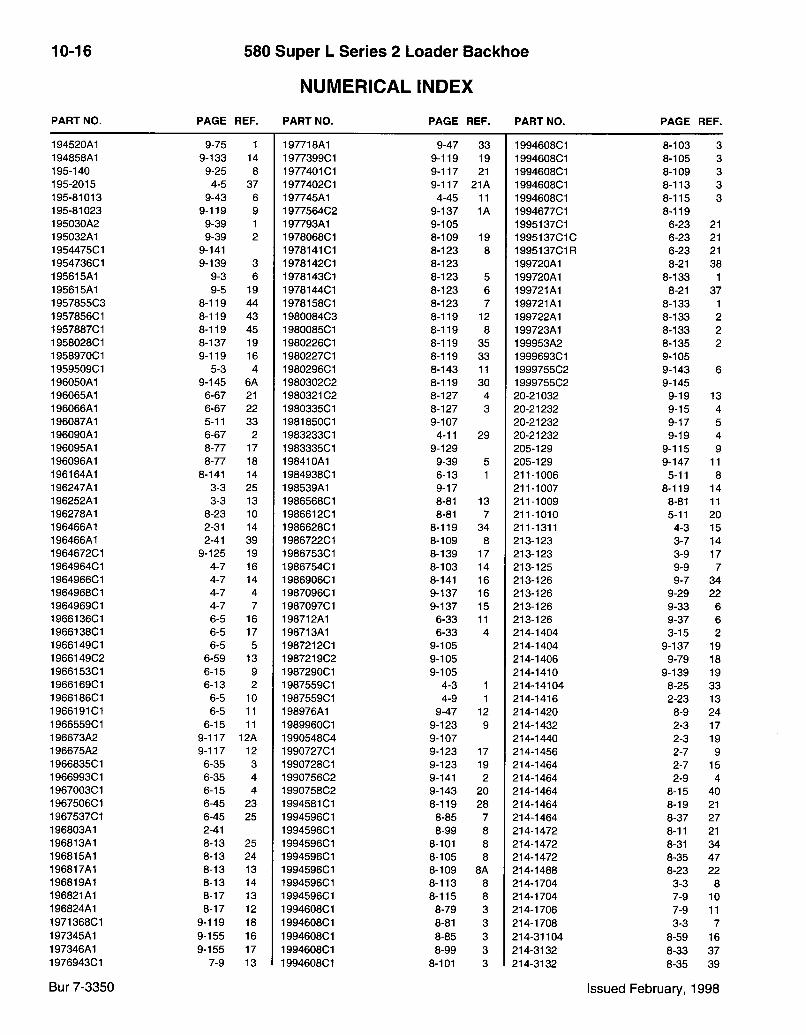
10-16 580 Super L Series 2 Loader Backlioe
NUMERICAL INDEX
P A R T N O . P A G E R E F . P A R T N O . P A G E R E F . P A R T N O . P A G E R E F .
194520A1 9-75 1 197718A1 9-47 33 199460801 8-103 3 194858A1 9-133 14 197739901 9-119 19 199460801 8-105 3 195-140 9-25 8 197740101 9-117 21 199460801 8-109 3 195-2015 4-5 37 197740201 9-117 21A 199460801 8-113 3 195-81013 9-43 6 197745A1 4-45 11 199460801 8-115 3 195-81023 9-119 9 197756402 9-137 1A 199467701 8-119 195030A2 9-39 1 197793A1 9-105 199513701 6-23 21 195032A1 9-39 2 197806801 8-109 19 1995137010 6-23 21 195447501 9-141 197814101 8-123 8 199513701R 6-23 21 195473601 9-139 3 197814201 8-123 199720A1 8-21 38 195615A1 9-3 6 197814301 8-123 5 199720A1 8-133 1 195615A1 9-5 19 197814401 8-123 6 199721A1 8-21 37 195785503 8-119 44 197815801 8-123 7 199721A1 8-133 1 195785601 8-119 43 198008403 8-119 12 199722A1 8-133 2 195788701 8-119 45 198008501 8-119 8 199723A1 8-133 2 195802801 8-137 19 198022601 8-119 35 199953A2 8-135 2 195897001 9-119 16 198022701 8-119 33 199969301 9-105 195950901 5-3 4 198029601 8-143 11 199975502 9-143 6 196050A1 9-145 6A 198030202 8-119 30 199975502 9-145 196065A1 6-67 21 198032102 8-127 4 20-21032 9-19 13 196066A1 6-67 22 198033501 8-127 3 20-21232 9-15 4 196087A1 5-11 33 198185001 9-107 20-21232 9-17 5 196090A1 6-67 2 198323301 4-11 29 20-21232 9-19 4 196095A1 8-77 17 198333501 9-129 205-129 9-115 9 196096A1 8-77 18 198410A1 9-39 5 205-129 9-147 11 196164A1 8-141 14 198493801 6-13 1 211-1006 5-11 8 196247A1 3-3 25 198539A1 9-17 211-1007 8-119 14 196252A1 3-3 13 198656801 8-81 13 211-1009 8-81 11 196278A1 8-23 10 198661201 8-81 7 211-1010 5-11 20 196466A1 2-31 14 198662801 8-119 34 211-1311 4-3 15 196466A1 2-41 39 198672201 8-109 8 213-123 3-7 14 196467201 9-125 19 198675301 8-139 17 213-123 3-9 17 196496401 4-7 16 198675401 8-103 14 213-125 9-9 7 196496601 4-7 14 198690601 8-141 16 213-126 9-7 34 196496801 4-7 4 198709601 9-137 16 213-126 9-29 22 196496901 4-7 7 198709701 9-137 15 213-126 9-33 6 196613601 6-5 16 198712A1 6-33 11 213-126 9-37 6 196613801 6-5 17 198713A1 6-33 4 214-1404 3-15 2 196614901 6-5 5 198721201 9-105 214-1404 9-137 19 196614902 6-59 13 198721902 9-105 214-1406 9-79 18 196615301 6-15 9 198729001 9-105 214-1410 9-139 19 196616901 6-13 2 198755901 4-3 1 214-14104 8-25 33 196618601 6-5 10 198755901 4-9 1 214-1416 2-23 13 196619101 6-5 11 198976A1 9-47 12 214-1420 8-9 24 196655901 6-15 11 198996001 9-123 9 214-1432 2-3 17 196673A2 9-117 12A 199054804 9-107 214-1440 2-3 19 196675A2 9-117 12 199072701 9-123 17 214-1456 2-7 9 196683501 6-35 3 1990728C1 9-123 19 214-1464 2-7 15 196699301 6-35 4 199075602 9-141 2 214-1464 2-9 4 196700301 6-15 4 199075802 9-143 20 214-1464 8-15 40 196750601 6-45 23 199458101 8-119 28 214-1464 8-19 21 196753701 6-45 25 199459601 8-85 7 214-1464 8-37 27 196803A1 2-41 199459601 8-99 8 214-1472 8-11 21 196813A1 8-13 25 199459601 8-101 8 214-1472 8-31 34 196815A1 8-13 24 199459601 8-105 8 214-1472 8-35 47 196817A1 8-13 13 199459601 8-109 8A 214-1488 8-23 22 196819A1 8-13 14 199459601 8-113 8 214-1704 3-3 8 196821A1 8-17 13 199459601 8-115 8 214-1704 7-9 10 196824A1 8-17 12 199460801 8-79 3 214-1706 7-9 11 197136801 9-119 18 199460801 8-81 3 214-1708 3-3 7 197345A1 9-155 16 199460801 8-85 3 214-31104 8-59 16 197346A1 9-155 17 199460801 8-99 3 214-3132 8-33 37 197694301 7-9 13 199460801 8-101 3 214-3132 8-35 39
Bur 7-3350 Issued February, 1998
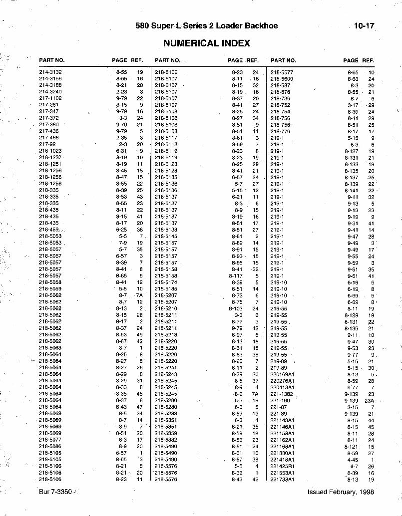
580 Super L Series 2 Loader Backhoe
NUMERICAL INDEX
10-17
PART NO. PAGE REF. PART NO. PAGE REF. PART NO. PAGE REF.
214-3132 8-55 19 218-5106 8-23 24 218-5577 8-65 10 214-3156 8-55 16 218-5107 8-11 16 218-5600 8-63 24 214-3188 8-21 28 218-5107 8-15 32 218-587 8-3 20 214-3240 2-23 3 218-5107 8-19 . 18 218-676 8-55. 21 217-1102 9-79 22 218-5107 8-37 . 20 218-736 8-7 6 217-281 3-15 9 218-5107 8-41 27 218-752 3-17 29 217-347 9-79 16 218-5108 8-25 24 218-754 8-39 24 217-372 3-3 24 218-5108 8-27 34 218-756 8-41 29 217-380 9-79 21 218-5108 8-51 9 218-756 8-51 25 217-436 9-79 5 218-5108 8-51 11 218-776 8-17 17 217-466 2-35 3 218-5117 8-61 3 219-1 5-15 9 217-92 2-3 .20 218-5118 8-59 7 219-1 6-3 6 218-1023 6-31 • 9 218-5119 8-23 8 219-1 8-127 19 218-1237 8-19 10 218-5119 8-23 19 219-1 8-131 21 218-1251 8-19 11 218-5123 8-25 29 219-1 8-133 19 218-1256 8-45 15 . 218-5128 8-41 21 219-1 8-135 20 218-1256 8-47 15 218-5135 6-57 24 219-1 8-137 25 218-1256 8-55 22 218-5136 5-7 27 219-1 8-139 22 218-335 8-39 25 218-5136 5-15 12 219-1 8-141 22 218-335 8-53 43 218-5137 6-21 11 219-1 9-11 32 218-335 8-55 23 218-5137 8-3 6 219-1 9-13 5 218-435 8-11 22 218-5137 8-9 15 219-1 9-13 23 218-435 8-15 41 218-5137 8-19 16 219-1 9-19 9 218-435 8-17 20 218-5137 8-51 17 219-1 9-31 41 218-459. 6-25 38 218-5138 8-51 27 219-1 9-41 14 218-5053 5-5 7 • 218-5145 8-61 2 219-1 9-47 28 218-5053 . 7-9 19 218-5157 8-89 14 219-1 9-49 3 218-5057 5-7 35 218-5157 8-91 15 219-1 9-49 17 218-5057 6-57 3 218-5157 8-93 15 219-1 9-55 24 218-5057 8-39 7 218-5157 . 8-95 15 219-1 9-59 3 218-5057 8-41 8 218-5158 8-41 32 219-1 9-61 35 218-5057 8-65 5 218-5158 8-117 5 219-1 9-61 41 218-5058 8-41 12 218-5174 8-39 5 219-10 6-19 5 218-5059 5-5 10 218-5185 8-51 14 219-10 6-19,. 8 218-5062 8-7 7A 218-5207 8-73 6 219-10 6-69 5 218-5062 8:7 12 218-5207 8-75 7 219-10 6-69 8 218-5062 8-13 2 . 218-5210 8-103 24 219-55 8-11 19 218-5062 8-15 28 218-5211 3-3 6 219-55 8-129 19 218-5062 8-17 2 218-5211 8-77 3 219-55 8-131 22 218-5062 8-37 24 218-5211 9-79 12 219-55 8-135 21 218-5062 8-53 49 218-5213 8-97 6 219-55 9-11 10 218-5062 8-67 42 218-5220 8-13 18 219-55 9-47 30 218-5063 8-7 1 218-5220 8-61 15 219-55 9-53 23 218-50.64 8-25 8 218-5220 8-63 38 219-55 9-77 9 218-5064 8-27 8 218-5220 8-65 7 219-89 - 5-15 21 218-5064 8-27 26 218-5241 8-11 2 219-89 5-15 , 30 218-5064 8-29 8 218-5243 8-39 20 220169A1 8-13 5 218-5064 8-29 31 218-5245 8-5 37 220276A1 8-59 28 218-5064 8-33 8 218-5245 8-9 4 220413A1 9-77 7 218-5064 8-35 45 218-5245 8-9 7A 221-1382 9-139 23 218-5064 8-37 8 218-5280 5-5 ,19 221-190 9-139 23A 218-5064 8-43 47 218-5280 6-3 5 221-87 3-15 7 218-5069 8-5 34 218-5283 8-59 13 221-89 9-139 21 218-5069 8-7 14 218-5351 6-3 4 221143A1 8-15 44 218-5069 8-9 7 218-5351 8-21 35 221146A1 8-15 45 218-5069 8-51 20 218-5359 8-59 18 221158A1 8-11 28 218-5077 8-3 17 218-5382 8-59 23 221162A1 8-11 24 218-5086 8-9 20 218-5490 8-51 24 221168A1 8-121 15 218-5105 6-57 1 218-5490 8-61 16 221330A1 8-59 27 218-5105 8-65 3 218-5490 • 8-67 .38 221418A1 4-45 1 218-5106 8-21 8 218-5576 5-5, 4 221425R1 4-7 26 218-5106 8-21 20 218-5576 8-39 1 221553A1 8-39 16 218-5106 8-23 11 218-5576 8-43 42 221733A1 8-13 19
Bur 7-3350 - Issued February, 1998

10-18 580 Super L Series 2 Loader Backhoe
NUMERICAL INDEX PART NO. PAGE REF. PART NO. PAGE REF. PART NO. PAGE REF.
222-41 3-15 10 231-14109 9-93 15 235002A1 8-63 26 222-615 2-13 231-14109 9-99 20 235038A1 2-3 35 222-650 2-13 4 231-14109 9-117 14 235040A1 2-3 34 222-660 2-13 5 231-1444 4-33 6 235916A1 8-141 1 222-993 2-23 16 231-1444 4-33 11 235917A2 8-141 2 222421A1 2-9 6 231-1444 4-45 4 235921A1 8-141 4 222422A1 2-9 7 231-1444 9-105 236231A1 8-9 14 222688A1 6-59 20 231-1444 9-149 12 236300A1 2-39 223-26 8-57 11 231-1445 4-33 16 236521A1 4-17 8A 223199A1 9-95 16 231-1446 8-59 6 237-6002 8-119 7 223722A1 7-13 29 231-1446 9-3 18 237-6004 5-5 8 223944A1 2-7 8 231-1446 9-5 28 237-6004 7-9 19A 224423A1 5-5 9 231-2446 9-37 18 237-6004 8-73 7 224788A2 8-41 2 231-4115 9-149 9 237-6004 8-75 8 225-14105 9-5 5 231-4247 9-45 21 237-6006 5-5 3 225-14106 4-27 20 231-5144 4-35 6 237-6006 5-7 36 225-14110 4-23 17 231-5145 9-117 23 237-6006 6-3 4A 225-14210 3-7 13 231-5344 9-123 8 237-6006 6-3 5A 225-14210 3-9 20 231397A1 6-15 237-6006 6-57 2 225-14210 8-49 29 231520A2 4-17 8 237-6006 6-57 4 225033A1 2-11 5 231656A1 9-79 6 237-6006 6-57 25 225059A1 9-121 27 231982A1 8-11 7 237-6006 8-21 36 225326A1 8-17 4 231984A1 8-11 5 237-6006 8-39 8 225328A1 8-17 5 232-4617 9-103 19 237-6006 8-39 21 225330A1 8-11 4 232-4617 9-103 26 237-6006 8-41 9 225332A1 8-11 6 232366A1 2-3 16 237-6006 8-41 31 225713A1 9-139 18 232447A1 8-13 4 237-6006 8-59 14 225714A1 9-139 31 232875A1 9-27 15 237-6006 8-65 4 226376A1 9-127 5 232929A1 8-11 29 237-6006 8-65 6 226378A1 2-9 232931A1 8-11 32 237-6006 8-125 4 226456A1 9-81 36 232934A1 8-15 46 237-6006 8-137 20 226560A1 9-105 232936A1 8-15 47 237-6006 9-79 17 226580A1 9-127 21 232939A1 8-11 30 237-6008 5-5 11 226582A1 9-127 20 232941A1 8-11 31 237-6008 5-5 20 226584A1 9-127 19 232945A1 8-17 19 237-6008 5-7 28 227178A2 9-115 23 232947A1 8-17 21 237-6008 5-15 13 227293A1 2-11 3 232948A1 9-143 19 237-6008 6-57 12 227420A1 9-115 18 233262A1 9-93 25 237-6008 8-21 9 228120A1 2-7 1 233272A1 2-3 4 237-6008 8-21 21 228120A1 2-9 233283A1 6-47 1 237-6008 8-23 12 228133A1 2-3 27 233284A1 6-45 32 237-6008 8-23 25 228689A1 9-121 233522A1 9-91 2 237-6008 8-41 13 228959A1 8-9 9 233523A1 9-91 1 237-6008 8-41 22 229398A2 9-93 24 233724A1 9-95 15 237-6008 8-59 19 229676A1 9-85 1 233749A1 9-89 237-6008 8-61 2A 229684A1 8-95 13 233970A1 6-21 15 237-6008 8-61 3A 230-4214 9-121 16 233971A1 6-21 16 237-6008 8-63 24A 230-4215 9-119 12 233972A1 6-21 13 237-6008 8-83 3 230-4215 9-121 11 234223A1 9-109 9 237-6008 8-103 25 230-4216 9-45 23 234277A1C 2-39 237-6010 3-3 6A 230-4216 9-45 30 234277A2 2-39 237-6010 5-5 5 230-4217 9-121 21 234277A2R 2-39 237-6010 6-21 12 230-42409 9-123 16 234412A1 8-63 23 237-6010 8-3 7 230072A1 8-61 19 234412A1 8-123 237-6010 8-7 7B 230073A1 8-61 20 234499A1 6-21 17 237-6010 8-7 13 230078A2 8-61 17 234622A1 7-7 34 237-6010 8-9 10 230513A1 9-75 5 234623A1 7-7 33 237-6010 8-9 16 230588A1 9-121 13 234719A1 6-21 14 237-6010 8-11 3 230589A1 9-121 12A 234888A1 3-3 19 237-6010 8-11 17 230590A1 9-121 12 234892A1 3-3 14 237-6010 8-13 3 230857A1 9-79 1A 234913A1 9-95 1 237-6010 8-15 29 230973A1 7-7 26 234923A1 9-91 35 237-6010 8-15 33 231-14109 9-83 4 234923A1 9-93 35 237-6010 8-17 3
Bur 7-3350 Issued February, 1998
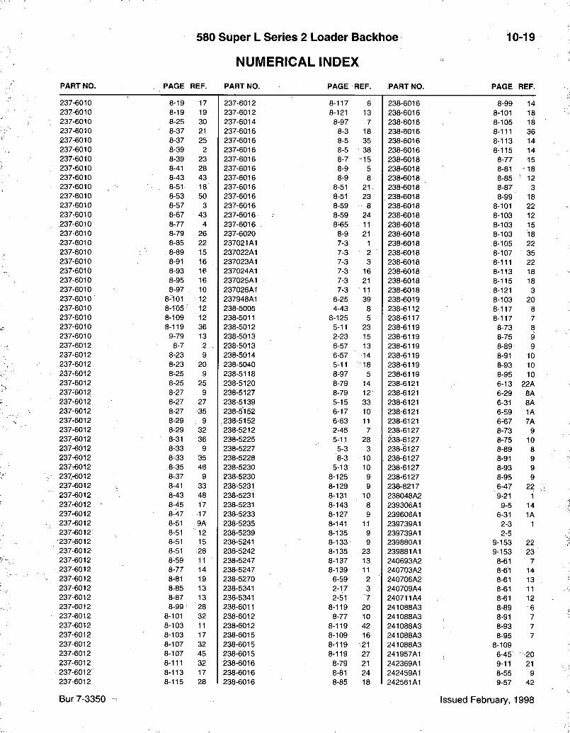
580 Super L Series 2 Loader Backhoe
NUMERICAL INDEX
10-19
PART NO. PAGE REF. PART NO. PAGE REF. PART NO. PAGE REF.
237-6010 8-19 17 237-6012 8-117 6 238-6016 8-99 14 237-6010 8-19 19 237-6012 8-121 13 238-6016 8-101 18 237-6010 8-25 30 237-6014 8-97 7 238-6016 8-105 18 237-6010 8-37 21 237-6016 8-3 18 238-6016 8-111 36 237-6010 8-37 25 237-6016 8-5 35 238-6016 8-113 14 237-6010 8-39 2 237-6016 8-5 38 238-6016 8-115 14 237-6010 8-39 23 237-6016 8-7 •15 238-6018 8-77 15 237-6010 8-41 28 237-6016 8-9 5 238-6018 8-81 18 237-6010 8-43 43 237-6016 8-9 8 238-6018 8-85 ' 12 237-6010 8-51 18 237-6016 8-51 21 238-6018 8-87 3 237-6010 8-53 50 237-6016 8-51 23 . . 238-6018 8-99 18 237-6010 8-57 3 237-6016 8-59 8 238-6018 8-101 22 237-6010 8-67 43 237-6016 8-59 24 238-6018 8-103 12 .237-6010 8-77 4 237-6016 8-65 11 238-6018 8-103 15 237-6010 8-79 26 237-6020 8-9 21 238-6018 8-103 18 237-6010 8-85 22 237021A1 7-3 1 238-6018 8-105 22 237-6010 8-89 15 237022A1 7-3 2 238-6018 8-107 35 237-6010 8-91 16 , 237023A1 7-3 3 238-6018 8-111 22 237-6010 8-93 16 237024A1 7-3 16 238-6018 8-113 18 237-6010 8-95 16 237025A1 7-3 21 238-6018 8-115 18 237-6010 8-97 10 237026A1 7-3 11 238-6018 8-121 3 237-6010 8-101 12 237948A1 6-25 39 238-6019 8-103 20 237-6010 8-105 12 238-5005 4-43 8 238-6112 8-117 8 237-6010 8-109 12 238-5011 8-125 5 238-6117 8-117 7 237-6010 8-119 36 238-5012 5-11 23 238-6119 8-73 8 237-6010 9-79 13 238-5013 2-23 15 238-6119 8-75 9 237-6012 8-7 2 238-5013 6-57 13 238-6119 8-89 9 237-6012 8-23 9 238-5014 6-57 14 238-6119 8-91 10 237-6012 8-23 20 238-5040 5-11 = 18 238-6119 8-93 10 237-6012 8-25 9 238-5118 8-97 5 238-6119 8-95 10 237-6012 8-25 25 238-5120 8-79 14 238-6121 6-13 22A 237-6012 8-27 9 238-5127 8-79 12 238-6121 6-29 8A 237-6012 8-27 27 238-5139 5-15 33 238-6121 6-31 8A 237-6012 8-27 35 238-5152 6-17 10 238-6121 6-59 1A 237-6012 8-29 : 9 .238-5152 6-63 11 238-6121 6-67 7A 237-6012 8-29 32 238-5212 2-45 7 238-6127 8-73 9 237-6012 8-31 36 238-5225 5-11 28 238-6127 8-75 10 237-6012 8-33 9 238-5227 5-3 3 238-6127 8-89 8 237-6012 8-33 35 238-5228 8-3 10 238-6127 8-91 9 237-6012 ,8-35 46 238-5230 5-13 10 238-6127 8-93 9 237-:6012 8-37 9 238-5230 8-125 9 238-6127 8-95 9 237-6012 8-41 33 238-5231 8-129 9 238-8217 6-47 22 237-6012 8-43 48 238-5231 8-131 10 238048A2 '9-21 1 237-6012 8-45 17 238-5231 8-143 8 239306A1 9-5 14 237-6012 8-47 17 238-5233 8-127 9 239606A1 6-31 1A 237-6012 8-51 9A 238-5235 8-141 11 239739A1 2-3 1 237-6012 8-51 12 238-5239 8-135 9 239739A1 2-5 237-6012 8-51 15 238-5241 8-133 9 239880A1 9-153 22 237-6012 8-51 28 238-5242 8-135 23 239881A1 9-153 23 237-6012 8-59 11 238-5247 8-137 13 240693A2 8-61 7 237-6012 8-77 14 238-5247 8-139 • 11 240703A2 8-61 14 237-6012 8-81 19 238-5270 6-59 2 240706A2 8-61 13 237-6012 8-85 13 238-5341 2-1.7 3 240709A4 8-61 11 237-6012 8-87 13 238-5341 2-51 7 240711A4 8-61 12 237-6012 8-99 28 238-6011 8-119 20 241088A3 8-89 6 237-6012 8-101 32 238-6012 8-77 10 241088A3 8-91 7 237-6012 8-103 11 238-6012 8-119 42 241088A3 8-93 7 237-6012 8-103 17 238-6015 8-109 16 241088A3 8-95 7 237-6012 8-107 32 238-6015 8-119 21 241088A3 8-109 237-6012 8-107 45 238-6015 8-119 27 241957A1 6-45 •20 237-6012 8-111 32 238-6016 8-79 21 242369A1 9-11 21 237-6012' 8-113 17 238-6016 8-81 24 242459A1 8-55 9 237-6012 8-115 28 238-6016 8-85 18 242561A1 9-57 42
Bur 7-3350 Issued February, 1998

10-20 580 Super L Series 2 Loader Backhoe
NUMERICAL INDEX PART NO. PAGE REF. PART NO. PAGE REF. PART NO. PAGE REF.
242562A1 9-57 40 247746A1 6-33 13 257954A1 8-71 242724A1 9-143 7 247748A1 6-33 18 258313A1 9-103 2 243084A1 9-47 19 247749A1 6-33 258616A1 9-3 243122A1 9-95 9 247877A1 6-67 24 258616A1 9-7 243135A1 8-89 248071A1 7-3 25863R1 8-129 17 243136A1 8-89 249773A1 8-53 41 25863R1 8-143 16 243137A1 8-93 249775A1 8-53 40 259044A1 8-3 1 243138A1 8-93 249867A1 9-47 1 259054A1 9-105 243139A2 8-91 250648A1 8-15 35 259071A1 9-103 2A 243141A2 8-91 250851A1 9-13 7 259410A1 9-43 16 243142A2 8-95 250851A1 9-19 26 25974R1 8-127 17 243143A2 8-95 250854A1 4-15 10 25974R1 8-131 19 243145A3 8-89 6A 252737A1 8-53 38 259777A3 8-65 1 243145A3 8-91 7A 252883A1 8-55 2 25987R1 8-139 20 243145A3 8-93 7A 252885A1 8-55 1 260-14512 9-147 30 243145A3 8-95 7A 253038A1 8-55 4 260-16524 9-119 14 243145A3 8-109 253209A1 9-111 8 261-14310 4-37 4 243291A1 8-55 20 253394A1 9-25 2A 261-14310 4-37 11 243338A1 8-43 44 253404A1 9-143 21 265-16512 9-117 19 243339A1 8-39 3 253740A1 8-53 37 273-10510 4-33 3 243603A1 9-135 8 253889A1 9-93 26 273-10510 4-33 9 243679A1 8-55 14 253989A2 8-89 4 273-5048 4-35 3 243790A1 8-7 7 253989A2 8-91 5 275454A1 3-9 21 243805A2 6-21 6 253989A2 8-93 5 275455A1 3-9 25 243893A1 7-3 253989A2 8-95 5 275456A1 3-9 22 244286A1 9-93 23 253989A2 8-103 275457A1 3-9 29 244287A1 9-93 21 254686A1 6-27 1 275464A1 2-7 10 244441A1 9-91 36 254729A1 2-13 18 275488A2 8-67 36 245011A1 9-89 1 255051A1 8-55 5 275547A1 9-105 1 245258A1 9-125 8 255291A1 3-9 4 275547A1 9-107 1 245287A1 3-9 14 255447A1 9-93 27 275677A1 9-43 3 245450A1 9-87 3 255450A1 9-117 275820A3 9-43 1 245450A1 9-89 4 255453A1 9-117 15 275967A1 2-11 1 245466A1 9-63 6 255659A1 8-23 23 276-2446 8-127 11 245466A1 9-63 9 255687A1 9-93 30 276-2446 8-129 11 245466A1 9-65 6 255927A1 8-63 33 276-2446 8-131 12 245466A1 9-65 6 255927A1 9-157 19 276-2446 8-133 11 245466A1 9-65 9 256091A1 8-29 30 276-2446 8-135 11 245466A1 9-65 9 256210A1 8-55 14A 276-2446 8-137 15 245466A1 9-67 6 256318A1 8-63 34 276-2446 8-139 13 245466A1 9-67 6 256318A1 9-157 21 276-2446 8-141 13 245466A1 9-67 9 256347A1 9-3 276-2446 8-143 10 245466A1 9-67 9 256347A1 9-7 276-2456 8-123 3 245466A1 9-69 6 256412A1 8-51 30 276-24916 2-13 8 245466A1 9-69 9 256478A1 7-5 13 276070A1 9-43 12 245466A1 9-71 6 256481A1 7-5 14 276743A1 7-9 16 245466A1 9-71 6 256482A1 7-5 17 276746A1 7-9 17 245466A1 9-71 9 256483A1 7-5 5 276962A1 8-65 12 245466A1 9-71 9 256485A1 7-5 18 277016A1 4-11 30 245592A1 9-39 256776A1 3-9 5 277184A2 9-25 16 245706C1 9-125 256888A3 6-35 277187A1 9-25 4A 245891A2 4-25 1 256888A3 6-37 277320A1 8-65 2 246060A1 9-143 14 256888A3 6-41 277377R1 2-9 2 246063A1 9-89 5 256888A3 6-43 277502A1 9-87 1 246064A1 9-89 6 257279A1 4-13 16 277546A1 9-145 7 246151A1 8-55 17 257279A1 4-15 11 277664A1 9-87 4 246158A1 8-55 15 257381A1 9-93 28 278183A1 3-9 28 246228A1 9-93 36 257382A1 9-93 29 278328A1 4-17 8 246767A1 6-33 20 257387A1 8-97 3 278534A1 6-27 8 247550A1 6-67 13 257434A1 2-5 2 278665A4 4-19 26A 247570A1 7-9 18 257810A1 9-43 18 278735A1 8-97 12 247743A1 2-9 8 257948A1 8-3 278735A1 8-101 14 247744A1 6-33 2 257954A1 8-3 11 278735A1 8-105 14
Bur 7-3350 Issued February, 1998
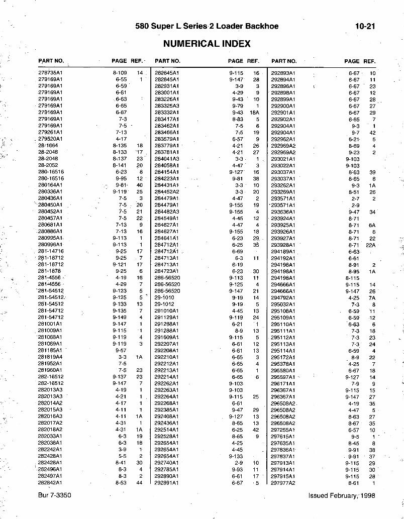
580 Super L Series 2 Loader Backhoe
NUMERICAL INDEX
10-21
PART NO. PAGE REF. PART NO. PAGE REF. PART NO. PAGE REF.
278735A1 8-109 14 282845A1 9-115 16 292893A1 6-67 10 279169A1 6-55 1 282845A1 9-147 28 292894A1 6-67 11 279169A1 6-59 282931A1 3-9 3 292896A1 6-67 23 279169A1 6-61 283001A1 4-29 9 292898A1 6-67 12 279169A1 - 6-63 283226A1 9-43 10 292899A1 6-67 28 279169A1 6-65 283325A3 9-79 1 292900A1 6-67 27 279169A1 6-67 283332A1 9-43 18A 292901A1 6-67 29 279169A1 7-3 283417A1 8-83 5 292902A1 6-65 7 279169A1 7-5 283462A1 7-5 6 292904A1 9-3 1 279261A1 7-13 283466A1 7.5 19 292904A1 9-7 42 279520A1 4-17 283579A1 6-57 9 292962A1 6-21 5 28-1664 8-135 18 283779A1 4-21 26 292969A2 8-69 4 28-2048 8-133 17 283781A1 4-21 27 292969A2 9-23 2 28-2048 8-137 23 284041 A3 3-3 1 - 293021A1 9-103 28-2052 8-141 20 284058A1 4-47 3 293022A1 9-103 280-16516 6-23 8 284154A1 9-127 16 293037A1 8-63 39 280-16516 9-95 12 284223A1 9-81 38 293037A1 8-65 8 280164A1 9-81 40 284431A1 3-3 10 293262A1 9-3 1A 280336A1 9-119 25 284452A2 3-3 20 293269A1 8-51 26 280436A1 7-5 3 284479A1 4-47 2 293571A1 2-7 2 280450A1 7-5 20 284479A1 9-155 19 • 293571A1 2-9 280452A1 7-5 21 284482A3 9-155 4 293636A1 9-47 34 280457A1 7-5 22 284549A1 4-45 12 293924A1 8-71 280681A1 7-13 9 284627A1 4-47 4 293925A1 8-71 6A 280886A1 7-13 16 284627A1 9-155 18 293926A1 8-71 6 280995A1: 9-113 1 284641A1 6-23 29. : 293927A1 8-71 22 280996A1 9-113 1 284712A1 6-25 35 293928A1 8-71 22A 281-14716 9-25 17 284712A1 6-69 294189A1 6-63 281-18712 9-25 • 7 284713A1 6-3 11 294192A1 6-61 281-18712 9-121 17 284713A1 6-19 294198A1 8-91 2 281-1878 9-25 6 284723A1 6-23 30 294198A1 8-95 1A 281-4556 • 4-19 16 286-56520 9-113 11 294198A1 8-115 281-4556 4-29 7 286-56520 9-125 4 294666A1 9-115 14
•281-54512 9-123 5 286-56520 9-147 21 294666A1 9-147 26 281-5451 £ 9-125 5 ^ 29-1010 9-19 14 294792A1 4-25 7A 281-54512 9-133 13 29-1012 9-19 5 295032A1 7-3 8 281-54712 9-135 7 291010A1 4-45 13 295108A1 6-59 11 281-54712 9-149 4 291129A1 9-119 24 295109A1 6-59 12 281001A1 9-147 1 291288A1 6-21 1 295110A1 6-63 6 281009A1 9-115 1 291288A1 8-9 13 295111A1 7-3 18 281068A1 9-119 4 291609A1 9-115 5 295112A1 7-3 23 281069A1 9-119 3 292207A1 6-61 12 295113A1 7-3 24 281185A1 • 9-57 292208A1 6-61 13 295114A1 6-59 4 281819A4 3-3 1A 292210A1 6-65 3 295172A1 8-9 22 281952A1 7-5 292212A1 6-65 4 295378A1 4-25 7 281960A1 7-5 23 292213A1 6-65 1 295580A1 6-67 18 282-16512 9-137 23 292214A1 6-65 6 295597A1 > 9-127 14 282-16512 9-147 7 292262A1 9-103 296171A1 7-9 9 282013A3 4-19 1 292263A1 9-103 296367A1 9-115 15 282013A3 4-21 1 . 292264A1 9-115 25 296367A1 9-147 27 282014A2 4-17 1 292268A1 6-61 296508A2. 4-19 35 282015A3 4-11 1 292385A1 9-47 29 296508A2 4-47 5 282016A3 4-11 1A 292408A1 . 9-127 13 296508A2 8-63 27 282017A2 4-31 1 292436A1 8-65 13 296508A2 8-67 35 282018A2 4-31 1A 292514A1 6-25 42 297255A1 6-57 10 282033A1 6-3 19 292528A1 8-65 9 297615A1 9-5 1 282038A1 6-3 18 292654A1 4-25 297635A1 8-45 8 282242A1 3-9 1. 292654A1 4-45 297836A1 .9-91 38 282428A1 5-5 2 292654A1 9-133 297837A1 9-91 37 282428A1 8-41 30 292740A1 2-9 10 297913A1 9-115 29 282496A1 8-3 4 292785A1 9-93 11 297914A1 9-115 30 282497A1 8-3 2 292890A1 6-61 17 297915A1 9-115 28 282842A1 8-53 44 292891A1 6-67 • 5 297977A2 8-61 1
Bur 7-3350 Issued February, 1998
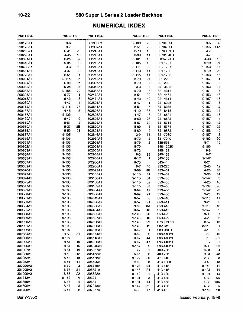
10-22 580 Super L Series 2 Loader Bacl<hoe
NUMERICAL INDEX PART NO. PAGE REF. PART NO. PAGE REF. PART NO. PAGE REF.
298176A1 9-3 301803R1 9-139 20 307348A1 3-5 39 298176A1 9-7 302097A1 8-51 22 307348A1 9-155 11A 298203A1 6-41 20 302246A1 8-79 18 3078897R1 4-7 298228A1 4-45 10 302246A1 8-99 11 3079134R1 4-7 6 298394A1 6-25 37 302246A1 8-101 15 3125705R1 4-43 10 298449A1 9-95 2 302246A1 8-105 15 321-1707 9-19 24 298463A1 3-3 10 302246A1 8-111 33 321-1707 9-153 17 298681A1 4-47 8 302246A1 8-113 11 321-1708 9-19 23 298772A1 8-51 1 302246A1 8-115 11 321-1708 9-153 16 299001A1 9-115 26 302247A1 8-79 24 321-229 9-157 1 299324A1 6-49 16 302326A1 8-79 7 321-230 9-157 3 299383A1 9-25 18 302358A1 3-3 3 321-3596 9-153 18 299383A1 9-155 20 302358A1 9-79 3 321-4311 9-151 5 299395A1 9-77 1 302472A1 8-51 29 321-4481 9-153 13 300013A1 9-49 18 302474A1 8-43 49 321-4614 9-157 18 300030A1 4-47 14 302501A1 8-47 1 321-6046 9-157 6 300152A1 9-115 27 302641A1 8-51 6 321-6376 9-157 2 300157A1 4-45 5 302803A1 4-19 36 321-6413 9-153 14 300157A1 9-133 302803A1 4-47 7 321-6671 9-153 15 300490A1 8-47 9 302803A1 8-63 37 321-6672 9-157 4 300580A1 8-51 2 302803A1 8-67 34 321-6714 9-153 12 300580A1 9-27 2B 302820A1 8-69 5 321-6774 9-157 22 300588A1 9-59 26 302821A1 8-69 9 321-6872 9-153 19 300657A1 9-105 302846A1 3-9 15 321-7030 9-157 8 300659A1 9-105 302964A1 8-73 2 321-7040 9-153 20 300661A1 9-105 302964A1 8-75 2 326-852 8-71 15 300662A1 9-105 302964A1 8-79 340-12520 9-105 300663A1 9-105 302965A1 8-73 345-133 9-3 300664A1 9-105 302965A1 9-3 28 345-133 9-7 300665A1 9-105 302966A1 8-17 1 345-133 9-147 300667A1 9-105 302966A1 8-75 345-44 6-21 300669A1 9-105 302966A1 9-7 40 353-225 2-45 12 300670A1 9-105 303022A1 9-99 8B 353-401 4-25 33 300672A1 9-105 303105A1 9-115 31 353-402 9-93 34 300674A1 9-105 303106A1 9-115 34 353-405 9-147 3 300675A1 9-105 303108A1 9-115 32 353-406 4-25 16 300677A1 9-105 303109A1 9-115 33 353-406 9-139 26 300679A1 9-105 303804A1 8-69 19 353-406 9-147 23 300680A1 9-105 303806A1 8-69 21 353-408 9-25 19 300681A1 9-105 304019A1 6-57 5 353-410 9-115 11 300683A1 9-105 304020A1 6-57 21 353-411 9-25 5 300684A1 9-105 304390A1 9-99 8A 353-415 9-115 10 300685A1 9-105 304424A1 8-67 40 353-417 9-147 5 300688A1 9-105 304525A1 9-145 28 353-422 9-95 7 300689A1 9-105 304527A1 9-145 18 353-429 4-25 32 300690A1 9-105 304528A1 9-145 29 376852R91 8-57 10 300691A1 9-105 304530A1 9-145 12 38-1812 8-119 31 300692A1 9-107 304572A1 8-69 1 383619R1 4-13 5 300884A1 8-53 51 304574A1 8-69 2 396-41028 9-3 16 300896A1 9-107 304612A1 8-67 44 396-41028 9-3 31 300905A1 8-51 10 304890A1 8-67 41 396-41028 9-7 31 300906A1 8-51 16 304940A1 9-157 5 396-41028 9-35 23 300907A1 8-51 19 305067A1 3-7 1 409-768 4-31 4 300939A1 8-53 42 305152A1 6-65 2 409-768 9-61 48 300952A1 8-53 48 305578A1 9-127 30 41-1616 2-39 8 300983A1 8-41 11 305690A1 9-89 3 413-1228 9-45 18 300996A2 8-69 3 305818A1 9-127 24 413-412 9-149 11 301008A2 8-65 21 305821A1 9-143 24 413-416 9-131 14 301009A2 8-65 22 305822A1 9-143 1 413-420 9-121 14 301343A1 9-153 1A 30634 8-131 3 413-432 4-33 5A 301355A1 8-47 4 30634 8-131 14 413-432 4-33 10A 301698A1 8-47 3 307243A1 9-147 31 413-432 4-35 5 301700A1 8-47 2 307277A1 8-69 17 413-48 9-119 20
Bur 7-3350 Issued February, 1998
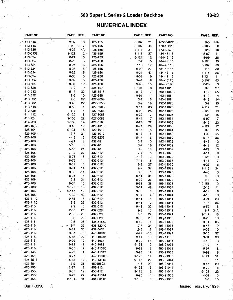
580 Super L Series 2 Loader Backhoe
NUMERICAL INDEX
10-23
PART NO. PAGE REF. PART NO. PAGE REF. PART NO. PAGE REF.
413-516 9-97 6 425-155 8-107 31 465004R91 9-3 14A 413-516 9-149 7 425-155 8-107 44 470-10620 9-103 8 413-536 4-33 14A 425-155 8-111 31 473321 C I 9-125 18 413-6152 9-121 2 425-155 8-115 27 484-43116 8-87 11 413-624 8-21 5 425-155 8-121 12 484-43116 8-99 26 413-624 8-23 5 425-156 7-7 5 484-43116 8-101 30 413-624 8-25 5 425-156 7-13 17 484-43116 8-107 30 413-624 8-27 5 425-156 9-29 27 484-43116 8-111 30 413-624 8-29 5 425-156 9-31 47 484-43116 8-115 26 413-624 8-33 .5 425-156 9-33 9 484-43116 8-121 11 413-624 8-37 5 425-156 9-41 9 484-43120 8-107 43 413-624 9-37 12 425-156 9-43 15 484-6316 6-23 3 413-628 9-3 19 425-157 9-131 3 490-11010 3-3 27 413-632 5-15 22 425-1918 5-17 7 490-1106 , 4-19 4A 413-632 9-5 10 425-285 9-97 11 490-1108 4-19 4 413-632 9-5 27 427-3058 3-7 15 490-1108 4-19 14 413-632 9-45 22 427-3058 3-9 18 492-11025 3-9 30 413-648 8-59 4 427-6088 9-11 33 492-11025 9-119 21 413-728 8-3 14 427-6088 9-29 25 492-11025 9-129 19 414-412 9-129 18 427-6088 9-33 7 492-11025 9-131 15 414-724 9-103 22 427-6088 9-41 7 492-11031 9-97 7 414-728 9-103 14 428-510 6-23 22 492-11038 5-15 23 425-1012 9-45 19 429-1010 8-71 20 492-11038 9-127 17 425-104 9-131 16 429-1012 9-15 5 492-11044 8-3 15 425-105- 7-7 21 429-1012 9-17 6 492-11050 4-33 6A 425-106 4-19 13 432-1232 5-17 6 492-11050 5-15 26 425-106 4-21 8 432-48 3-7 10 493-11026 4-43 2 425-106 5-13 5 432-48 3-7 16 493-11039 4-13 12 425-106 5-15 24 432-48 3-9 19 493-11052 4-29 3 425-106 7-13 27 432-612 7-7 8 493-21020 4-11 9 425-106 8-73 13 432-612 7-13 3 493-21020 8-125 3 425-106 8-75 14 432-612 7-13 18 493-21033 4-11 7 425-106 8-89 13 432-612 9-3 27 493-41020 6-23 5 425-106 8-91 14 432-612 9-7 37 495-11022 8-119 24 425-106 8-93 .14 432-612 9-9 5 495-11028 4-45 3 425-106 8-95 14 432-612 9-11 34 495-11028 9-3 8 425-106 9-3 21 432-612 9-29 26 495-11028 9-5 17 425-106 9-37 13 432-612 9-31 38 • 495-11028 9-151 2 425-106 9-127 18 432-612 9-31 49 495-11034 2-13 11 425-106 9-147 - 19 432-612 9-33 8 495-11041 4-13 9 425-108 4-33 6B 432-612 9-37 4 ' 495-11041 4-15 8 425-1110 9-35 16 432-612 9-41 8 495-11041 4-21 23 425-1120 8-3 22 432-612 9-41 12 495-11041 7-13 26 425-115 9-9 6 432-612 9-43 20 495-11041 8-59 5 425-116 2-35 24 432-828 ,9-3 13 495-11041 9-7 34A 425-116 2-35 28 432-828 9-5 24 495-11041 9-147 18 425-116 9-3 22 432-828 9-35 20 495-11053 . 6-23 10 425-116 9-5 26 435-51652 9-59 •4 495-11053 9-11 35 425-116 . - 9-7 38 438-12040 7-7 24 495-11053 9-43 9 425-116 9-31 36 439-5436 9-5 6 495-11081 9-35 10 425-116 9-37 .5 440-10616 4-47 •10 495-11094 5-15 37 425-118 5-15 27 440-10616 9-11 18 495-11106 9-91 33 425-118 9-29 10 440-1066 9-79 I B 495-21031 4-43 3 425-118 9-33 3 440-1088 9-133 12 495-21038 7-13 4 425-118 9-35 7 440-11010 9-83 2 495-21038 9-97 8 425-148 4-29 4 440-11012 9-93 12 495-21038 9-99 18 425-1510 8-77 8 442-11016' 9-123 14 495-21038 9-121 6A 425-1514 5-13 17 . 443-13112 9-117 22 495-21044 9-5 11 425-154 3-9 31 452698C1 4-5 29 495-21044 . 9-45 29 425-155 2-27 3 458-412 9-123 6 495-21044 9-79 8 425-155 8-87 12 458-412 9-125 16 495-21044 9-131 22 425-155;: 8-99 27 459-11014 6-23 4 495-21056 4-31 13 425-155 8-101 31 461-33148 9-135 3 495-21056 6-3 15
Bur 7-3350 Issued February, 1998
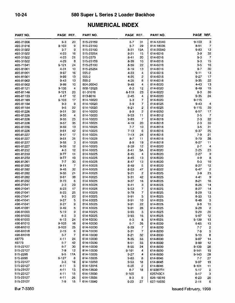
10-24 580 Super L Series 2 Loader Backhoe
NUMERICAL INDEX PART NO. PAGE REF. PART NO. PAGE REF. PART NO. PAGE REF.
495-21056 6-3 20 515-23159 5-7 31 614-12040 9-103 3 495-31016 9-103 9 515-23190 5-7 29 614-18035 8-51 7 495-31022 3-7 9 515-23190 8-21 15A 614-20040 9-83 12 495-31022 4-23 16 515-23254 8-21 15 614-6016 3-9 32 495-31022 4-23 21 515-2379 8-41 20 614-6016 9-3 7 495-31022 4-29 8 515-25159 8-39 10 614-6016 9-3 15 495-71041 9-121 24 515-25190 8-59 22 614-6016 9-5 16 495-81001 4-31 10 515-25254 8-19 13 614-6016 9-7 30 495-81001 9-97 16 555-2 4-23 4 614-6016 9-11 13 495-81001 9-99 13 555-2 4-25 2 614-6016 9-27 17 495-81002 9-43 13 555-2 4-25 8 614-6016 9-35 22 495-81002 9-99 10 604-20040 9-49 4 614-6020 4-43 13 495-81121 9-135 4 608-12025 6-3 12 614-6020 8-49 15 495-81148 9-121 20 61-31016 8-119 23 614-6020 9-3 30 495-81153 4-17 12 613-8016 2-45 4 614-6020 9-35 24 495-81169 9-103 17 614-10020 5-3 7 614-6020 9-115 495-81184 9-3 9 614-10020 5-9 7 614-6025 9-43 4 495-81184 9-5 22 614-10020 6-21 2 614-6025 9-115 20 495-81226 9-51 32 614-10020 8-9 2 614-6050 6-57 17 495-81226 9-55 4 614-10020 9-53 11 614-8012 2-5 7 495-81226 9-55 25 614-10020 9-83 7 614-8016 2-3 22 495-81226 9-57 35 614-10025 4-19 20 614-8016 2-3 33 495-81226 9-59 13 614-10025 7-7 10 614-8016 3-5 31 495-81226 9-61 42 614-10025 7-13 6 614-8016 6-37 25 495-81227 9-47 17 614-10025 7-13 24 614-8016 7-9 21 495-81227 9-51 31 614-10025 8-7 11 614-8016 9-79 28 495-81227 9-55 3 614-10025 8-9 19 614-8018 6-27 11 495-81227 9-59 12 614-10025 8-39 12 614-8020 2-7 4 495-81252 4-3 12 614-10025 8-41 5A 614-8020 2-25 23 495-81259 9-77 11 614-10025 8-45 4 614-8020 2-27 9 495-81259 9-77 19 614-10025 8-45 13 614-8020 4-9 8 495-81261 7-7 30 614-10025 8-47 13 614-8020 5-3 10 495-81282 9-11 7 614-10025 8-49 5 614-8020 9-27 12 495-81282 9-45 32 614-10025 8-53 47 614-8022 6-47 2 495-81282 9-55 21 614-10025 9-21 2 614-8025 3-9 23 495-81282 9-61 38 614-10025 9-31 42 614-8025 4-41 9 495-81292 9-73 6 614-10025 9-37 16 614-8025 8-21 16 496-21041 2-3 29 614-10025 9-41 3 614-8025 8-25 14 496-21041 6-23 17 614-10025 9-53 7 614-8025 8-27 14 496-21041 6-23 25 614-10025 9-79 7 614-8025 8-29 13 496-21041 9-3 20 614-10025 9-91 5 614-8025 8-33 13 496-41041 9-27 5 614-10025 9-91 10 614-8025 8-49 3 496-41041 9-27 9 614-10025 9-91 22 614-8025 9-9 15 496-41081 9-49 5 614-10025 9-91 28 614-8025 9-29 2 496-81000 5-19 9 614-10025 9-93 3 614-8025 9-29 20 496-81000 6-3 3 614-10025 9-93 16 614-8025 9-97 12 496-81000 6-13 24 614-10030 5-3 8 614-8025 9-139 13 496-81010 9-103 18 614-10030 5-7 26 614-8030 6-65 13 496-81010 9-103 25 614-10030 6-29 7 614-8030 7-7 2 496-81018 2-15 6 614-10030 6-31 7 614-8030 7-9 5 496-81018 3-7 7 614-10030 8-21 32 614-8030 9-13 8 49773 4-11 24 614-10030 8-35 53 614-8030 9-97 14 49773 5-7 42 614-10030 8-51 33 614-8030 9-99 12 515-22127 5-7 30 614-10030 8-55 24 614-8030 9-139 28 515-22127 7-9 12 614-10030 9-101 4 614-8030 9-141 19 515-2295 9-5 17A 614-10035 9-27 4 614-8030 9-143 28 515-2295 9-127 8 614-10035 9-83 8 614-8045 7-7 27 515-23127 3-3 16 614-10050 9-53 18 614-8045 9-97 19 515-23127 4-11 5 614-12016 6-35 2 614-8045 9-101 11 515-23127 4-11 13 614-12030 8-7 18 619387R1 5-17 2 515-23127 4-11 15 614-12030 9-105 625743C1 5-17 3 515-23127 4-11 26 614-12035 8-3 9 626-10016 6-23 26 515-23127 7-9 15 614-12040 6-23 27 627-10030 2-11 6
Bur 7-3350 Issued February, 1998
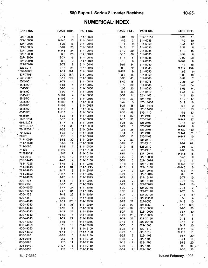
580 Super L Series 2 Loader Bacldioe
NUMERICAL INDEX
10-25
PART NO. PAGE REF. PART NO. PAGE REF. PART NO. PAGE REF.
627-10030 2-11 9 811-10070 9-81 39 814-16110 6-23 31 627-10030 9-145 13 814-10040 4-9 2 814-6035 7-3 10 627-10035 6-23 16 814-10040 8-11 9 814-6060 8-41 17 627-10035 8-69 20 814-10040 8-13 7 814-8035 2-27 8 627-10035 9-145 24 814-10040 8-13 20 814-8035 4-13 15 627-12030 3-9 26 814-10040 8-15 36 814-8035 4-31 8 627-12030 9-77 .16 814-10040 8-17 6 814-8035 9-97 20 627-20040 3-3 2 814-10040 8-19 8 814-8035 9-101 8 627-20040 9-79 2 814-10040 8-51 34 814-8040 7-7 15 628-6016. 3-17 21 814-10040 9-3 29 814-8045 9-117 15A 637-62081 4-11 30A 814-10040 9-127 9 814-8050 3-9 9 637-72081 2-39 16A 814-10045 3-5 38 814-8060 6-33 16 637-72081 3-17 27A 814-10045 8-35 41 814-8060 6-51 7 65457C1 8-79 4 814-10045 8-49 18 814-8075 •2-35 29 65457C1 8-81 4 814-10045 9-79 30 814-8080 6-49 34 65457C1 8-85 4 814-10050 2-3 23 814-8080 6-65 14 65457C1 8-99 4 814-10050 8-5 33 814-8110 4-41 4 65457C1 - 8-101 4 814-10050 8-37 14 824-1405 4-11 10 65457C1 8-103 4 814-10050 8-43 53 824-1405 4-47 • 17 65457C1 8-105 4 814-10050 8-47 5 825-11418 5-19 "8 6545701 8-109 4 814-10055 8-31 38 825-11418 6-3 2 65457C1 8-113 4 814-10055 8-33 30 825-11418 6-13 25 65457C1 8-115 4 814-10055 8-35 49 825-1410 4-5 .43 65881H 4-33 15 814-10060 4-11 27 825-2406 4-21 4 680187C1- 3-17 9 814-10060 7-13 30 825-2406 9-141 27 69129201 3-17 8 814-10060 8-21 22 825-2408 3-15 6 697494R91 5-11 30 814-10060 •9-27 8 825-2408 9-139 8 70-12532 ' 4-33 5 814-10070 2-3 28 825-2408 , 9-139 30 70-12532 4-33 10 814-10070 8-41 5 825-2408 9-141 21 70973 2-7 3 814-10070 8-55 10 825-2408 9-147 10 711-10030 8-63 30 814-10080 9-19 20 825-2410 3-17 24 711-10040 8-65 14 814-10090 8-69 13 825-2410 9-91 6A 711-6050' 8-65 17 814-10090 9-19 16 825-2410 9-91 27 71121 8-119 2 " 814-10100 4-9 5 825-2410 9-93 19 712998R91 6-7 7 814-10140 8-61 . 4 827-10040 9-145 16 733-2012 8-49 12 814-10150 6-29 9 827-10050 8-45 9 760-14413 4-45 14 814-10180 .8-51 3 827-10075 6-15 3 761-17325 4-45 8 814-10245 4-13-' 6 827-10110 9-145 19 781-24613 4-11 , 34 ' 814-10245 4-15 7 827-10130 • 9-145 8 781-24820 4-17 3 814-12045 3-7 ; 3 827-12045 6-3 14 781-24820 9-147 14 814-12045 8-21 2 827-12045 6-3 21 781-24830 9-97 4 814-12045 8-23 2 827-16110 9-77 10 800-1134 6-13 17 814-12045 8-25 2 827-16110 9-77 18 800-2136 6-67 26 814-12045 8-27 2 827:20075 9-47 13 800-40065 9-47 27 814-12045 8-29 2 827-20170 9-75 2 800-40070 9-47 31 814-12045 8-33 2 827-20170 9-75 6 800-4155 9-49 25 814-12045 8-37 2 827-20190 9-13 16 800-435 3-9 7 , 814-12050 8-41 3 ; 827-20230 6-55 4 800-44040 V 9-11 26 • 814-12060 8-29 27 827-8050 . 7 - 1 3 10 800-44040 9-11 31 814-12060 8-33 27 827-8060 7-13 10A 800-44040 9-13 4 814-12080 8-25 37 828-10060 8-65 25 800-44040: 9-13 22 814-12080 8-27 31 828-10090 8-67 30 800-44040 9-53 5 814-12080 8-29 23 828-12055 6-23 9 800-44040 9-59 27 814-12080 8-33 23 ' 828-20160 9-15 6 800-44050 5-15 4 814-12085 2-15 5 828-20160 9-17 7 800-44050 5-15 10 814-12090 8-55 6 829-1306 3-17 20 800-44050 6-3 7 814-12100 8-25 18 829-1310 8-117 13 800-44050 9-11 8 814-12100 8-27 18 829-1312 8-117 11 800-5120 6-65 • 5 814-12100 8-29 17 829-1406 6-57 20 806-8016 2-3 6 814-12100 8-33 17 829-1406 8-41 19 806-8025 2-7. 11 814-12110 2-15 2 829-1406 8-65 20 806-8040 ,- 9-127 . 6 814-12110 9-91 16 829-1406 9-3 32 806-8050 . 2-3 10 814-14140 6-59 9, 829-1406 9-35 25
Bur 7-3350 Issued February, 1998
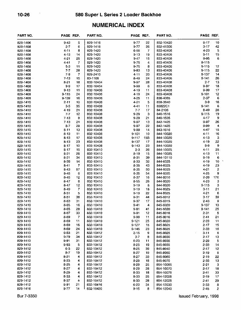
10-26 580 Super L Series 2 Loader Backhoe
NUMERICAL INDEX PART NO. PAGE REF. PART NO. PAGE REF. PART NO. PAGE REF.
829-1406 9-43 5 829-1416 9-77 22 832-10420 9-17 10 829-1408 2-7 6 829-1416 9-77 26 832-41306 3-17 42 829-1408 4-11 8 829-1420 6-55 7 833-40406 4-23 5 829-1408 4-13 14 829-1420 9-13 19 833-40406 9-11 15 829-1408 4-21 25 829-1420 9-47 15 833-40406 9-95 6 829-1408 4-41 7 829-1420 9-75 4 833-40406 9-115 829-1408 5-3 11 829-1420 9-75 8 833-40406 9-115 12 829-1408 7-7 28 829-1420 9-83 13 833-40406 9-115 22 829-1408 7-9 7 829-2410 4-11 20 833-40406 9-137 14 829-1408 7-13 15 83-1108 8-49 24 833-40406 9-141 26 829-1408 8-21 18 832-10404 9-97 28 833-40408 2-7 13 829-1408 9-9 17 832-10404 9-99 6 833-40408 9-97 18 829-1408 9-13 11 832-10406 4-19 11 833-40408 9-99 17 829-1408 9-115 24 832-10406 4-19 24 833-40408 9-101 12 829-1408 9-139 16 832-10406 4-25 11 836-4065 2-37 6 829-1410 2-11 10 832-10408 4-21 5 838-3640 3-9 16 829-1410 3-5 35 832-10408 4-41 11 83822C1 9-141 6 829-1410 4-19 21 832-10408 7-7 17 84-2106 8-49 28 829-1410 7-7 12 832-10408 9-29 3 840-1516 9-115 19 829-1410 7-13 8 832-10408 9-29 21 840-1535 4-17 9 829-1410 7-13 21 832-10408 9-97 13 842-1425 9-97 26 829-1410 8-7 29 832-10408 9-97 22 842-1425 9-99 4 829-1410 8-11 13 832-10408 9-99 14 843-1516 4-47 15 829-1410 8-13 11 832-10408 9-101 10 844-10020 4-11 16 829-1410 8-13 17 832-10408 9-117 15B 844-10020 4-13 3 829-1410 8-13 23 832-10408 9-137 17 844-10020 4-19 22 829-1410 8-17 10 832-10408 9-143 23 844-10020 9-9 9 829-1410 8-17 15 832-10410 2-3 26 844-10025 4-11 25 829-1410 8-21 26 832-10410 8-19 15 844-10025 4-13 11 829-1410 8-21 34 832-10410 8-31 39 844-10110 9-19 6 829-1410 8-39 14 832-10410 8-33 32 844-6025 4-19 10 829-1410 8-41 7 832-10410 8-35 43 844-6025 4-19 23 829-1410 8-43 57 832-10410 8-35 50 844-6025 4-21 2 829-1410 8-45 6 832-10410 8-35 54 844-6025 4-25 9 829-1410 8-45 12 832-10410 8-37 16 844-8016 2-39 17E 829-1410 8-47 8 832-10410 8-55 26 844-8020 4-23 3 829-1410 8-47 12 832-10410 9-19 8 844-8020 9-115 3 829-1410 8-49 7 832-10410 9-19 18 844-8025 3-11 21 829-1410 8-51 5 832-10410 9-19 22 844-8025 4-21 6 829-1410 8-51 36 832-10410 9-31 44 845-6012 3-17 39 829-1410 8-63 31 832-10410 9-37 17 845-6015 2-43 9 829-1410 8-65 16 832-10410 9-41 4 845-6020 9-137 13 829-1410 8-65 28 832-10410 9-81 41 845-6020 9-141 25 829-1410 8-67 33 832-10410 9-91 12 845-8016 2-31 5 829-1410 8-69 7 832-10410 9-99 11 845-8016 2-41 21 829-1410 8-69 11 832-10410 9-121 25 845-8020 2-23 11 829-1410 8-69 16 832-10410 9-127 15 845-8025 2-17 15 829-1410 8-69 24 832-10410 9-145 23 845-8025 2-33 16 829-1410 9-53 21 832-10412 2-15 9 845-8025 3-11 6 829-1410 9-79 34 832-10412 3-7 8 845-8030 2-17 13 829-1410 9-91 31 832-10412 6-23 11 845-8035 2-29 5 829-1410 9-93 5 832-10412 8-25 19 845-8035 2-33 14 829-1412 6-3 22 832-10412 8-25 39 845-8040 2-17 12 829-1412 8-7 19 832-10412 8-27 19 845-8050 2-19 6 829-1412 8-21 4 832-10412 8-27 33 845-8060 2-19 22 829-1412 8-23 4 832-10412 8-29 18 845-8070 2-33 13 829-1412 8-25 4 832-10412 8-29 25 854-10065 2-21 3 829-1412 8-27 4 832-10412 8-29 28 854-10070 2-17 18 829-1412 8-29 4 832-10412 8-33 18 854-10075 2-41 33 829-1412 8-33 4 832-10412 8-33 25 854-12025 2-19 17 829-1412 8-37 4 832-10412 8-33 28 854-12025 2-41 29 829-1412 9-91 21 832-10416 6-23 34 854-12030 2-33 8 829-1416 9-77 14 832-10420 9-15 8 854-12040 2-45 2
Bur 7-3350 Issued February, 1998

580 Super L Series 2 Loader Backhoe
NUMERICAL INDEX
10-27
PART NO. PAGE REF. PART NO. PAGE REF. PART NO. PAGE REF.
863-6020 7-3 25 892-11012 3-9 27 895-15008. 2-3 7 864-10025 6-35 17 892-11012 9-103 5 895-15008 2-7 12 864-12130 6-59 10 892-11012 9-105 895-15008 3-5 32 864-6020 6-49 8 892-11018 8-51 8 895-15008 4-13 13 864-6025 6-33 7 893-11005 4-45 15 895-15008 9-79 29 864-6035 7-3 19 893-11006 4-21 3 895-15008 9-127 7 864-8016 7-3 4 893-11008 4-41 3 895-15010 8-63 35 864-8020 6-49 21 895-11004 4-47 11 895-18010 9-43 19 864-8025 6-35 6 , 895-11004 9-97 27 896-11010 2-11 8 892-11005 4-5 40 895-11004 9-99 5 896-11010 8-11 11 892-11005 4-47 16 895-11005 3-9 6 896-11010 8-13 9
.892-11006 , 3-9 33 895-11006 3-9 34 896-11010 8-55 25 892-11006 3-17 19 895-11006 3-17 18 896-11010 9-3 29A 892-11006 4-3 11 895-11006 6-57 18 896-11010 9-21 3 892-11006 6-57 19 895-11006 8-41 18 896-11010 9-91 14 892-11006 8-49 17 895-11006 8-49 16 896-11010 9-145 9 892-11006 8-65 19 895-11006 8-65 18 896-11010 9-145 14 892-11006 9-27 19 895-11006 9-27 18 896-11010 9-145 22 892-11006 9-115 21 895-11008 2-3 11 896-11010 9-145 26 892-11008 3-9 10 895-11008 2-5 8 896-11012 3-7 4 892-11008 3-9 24 895-11008 2-7 5 896-11012 8-21 3 892-11008 4-21 24 895-11008 2-27 6 896-11012 8-23 3 892-11008 4-31 9 895-11008 3-9 11 896-11012 8-25 3 892-11008 7-7 3 895-11008 4-41 6 896-11012 8-27 3 892-11008 7-9 6 895-11008 4-41 10 896-11012 8-29 3 892-11008 7-13 14 895-11008 7-9 20 896-11012 8-33 3 892-11008 8-21 17 895-11008 8-49 4 896-11012 8-37 '3 892-11008 8-25 15 895-11008 9-9 16 896-11012 8-41 4 892-11008 8-27 15 895-11008 9-13 9 896-11012 9-53 22 892-11008 8-29 14 •895-11008 9-27 13 896-11012 9-77 17 892-11008 8-33 14 895-11008 9-97 21 896-11012 9-91 34 892-11008 9-13 10 895-11008 9-101 9 896-11012 9-103 118 892-11008 9-27 14 895-11008 9-119 26 896-11020 3-3 3A 892-11008 9-97 15 895-11008 9-125 15 896-11020 6-55 5 892-11008 9-99 16 895-11008 9-139 14 896-11020 9-13 18 892-11008 9-139 15 895-11008 9-143 22 896-11020 9-15 9 892-11008 9-147 15 895-11010 3-5 34 896-11020 9-17 9 892-11010 4-5 42 895-11010 6-21 3 896-11020 9-43 11 892-11010 7-7 11 f 895-11010 7-13 31 896-11020 9-47 14 892-11010 7-13 7 ' 895-11010 8-9 3 896-11020 9-75 3 892-11010 7-13 22 895-11010 8-15 38 896-11020 9-75 7 892-11010 8-11 12 895-11010 8-19 14 896-11020 9-79 3A 892-11010 8-13 10 895-11010 8-41 6 896-15012 2-15 3
- 892-11010 8-13 16 895-11010 8-45 14 896-15012 2-15 8 892-11010 8-13 22 895-11010 8-47 14 896-15012 6-23 28 892-11010 . 8 - 1 5 37 : 895-11010 8-49 6 896-15012 9-91 17 892-11010 8-17 9 895-11010 8-51 4 896-15012 9-91 20 892-11010 8-17 16 • 895-11010 8-61 5 90-6682T1 6-3 16 892-11010 8-19 9 895-11010 9-11 20 90-6682T1 6-19 12 892-11010 8-21 33 895-11010 9-19 17 90-668211 6-25 40 892-11010 8-47 7 895-11010 9-19 21 ' 90-668211 6-69 12 892-11010 8-51 35 895-11010 9-53 20 905794R1 6-35 20 892-11010 8-61 6 : 895-11010 9-91 6 905839R1 6-9 4 892-11010 8-65 15 895-11010 9-91 11 ' 905876R1 6-13 23 892-11010 8-65 27 895-11010 9-91 23 91946C1 4-33 2 892-11010 8-67 32 895-11010 9-91 29 91947C1 4-33 8 892-11010 8-69 6 895-11010 9-93 4 933697R1 3-17 7 892-11010 8-69 10 895-11010 9-93 6 934667R1 6-29 3 892-11010 8-69 15 895-11010 9-93 17 934667R1 6-31 3 892-11010 8-69 23 895-11010 9-101 6 934667R1 6-49 36 892-11010 9-53 12 895-11010 9-127 10 934667R1 6-51 6 892-11010 9-79 .31 895-15006 4-25 10 934727R1 6-9 2 892-11010 9-101 5 895-15006 9-115 96790C2 8-49 10
Bur 7-3350 Issued February, 1998
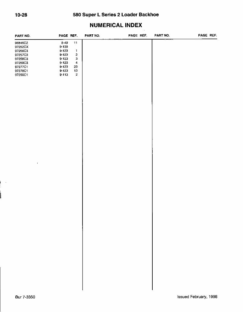
10-28 580 Super L Series 2 Loader Backhoe
NUMERICAL INDEX PART NO. PAGE REF.
96846C2 8-49 11 97252CX 9-139 97256C3 9-123 1 97257C3 9-123 2 97258C3 9-123 3 97259C3 9-123 4 97277C1 9-123 23 97278C1 9-123 13 97290C1 9-113 2
PART NO. PAGE REF. PART NO. PAGE REF.
Bur 7-3350 Issued February, 1998