800-643-7332 200 series lutv retro manual …...200 series lutv retro manual choke kit (15439) auto...
TRANSCRIPT
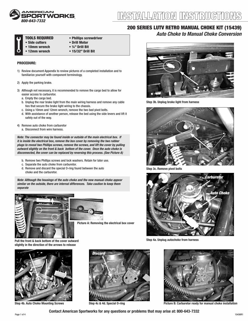
200 SERIES LUTV RETRO MANUAL CHOKE KIT (15439)Auto Choke to Manual Choke Conversion
800-643-7332
TOOLS REQUIRED •Phillipsscrewdriver•Sidecutters •DrillMotor•10mmwrench •¼”DrillBit•12mmwrench •15/32”DrillBit
PROCEDURE:
1) ReviewdocumentAppendixtoreviewpicturesofacompletedinstallationandto familiarizeyourselfwithcomponentterminology.
2) Applytheparkingbrake.
3) Althoughnotnecessary,itisrecommendedtoremovethecargobedtoallowfor easieraccesstocarburetor. a. Emptythecargobed. b. Unplugtherearbrakelightfromthemainwiringharnessandremoveanycable tiesthatsecurethebrakelightwiringtothechassis. c. Usinga10mmand12mmwrench,removethetwobedpivotbolts. d. Withassistanceofanotherperson,releasethebedusingthesideleversandliftit safelyoutoftheway.
4) Removeautochokefromcarburetor a. Disconnectfromwireharness.
Note: The connector may be found inside or outside of the main electrical box. If it is inside the electrical box, remove the box cover by removing the two rubber plugs to reveal two Phillips screws, remove the screws, and lift the cover by pulling outward slightly on the front & back bottom of the cover. Once the auto choke is disconnected, the cover can be replaced by reversing this process. (See Picture A)
b. RemovetwoPhillipsscrewsandlockwashers.Retainforlateruse. c. Separatetheautochokefromcarburetor. d. RemoveanddiscardthespecialO-ringfoundbetweentheauto chokeandthecarburetor.
Note: Although the housings of the auto choke and the new manual choke appear similar on the outside, there are internal differences. Take caution to keep them separate
Step 3b. Unplug brake light from harness
Step 3c. Remove pivot bolts
Carburetor
Auto Choke
Step 4a. Unplug autochoke from harness
Picture A: Removing the electrical box cover
Pull the front & back bottom of the cover outward slightly in the direction of the arrows to release
Picture B: Carburetor ready for manual choke installation
15436R1Page1of4
Step 4b. Auto Choke Mounting Screws Step 4c & 4d. Special O-ring
Discard
Contact American Sportworks for any questions or problems that may arise at: 800-643-7332

5) Installthemanualchokeassembly a. CarefullypositionthespecialO-ringbetweenthechokeandcarburetor assemblies. b. PositionthechokeassemblyonthecarburetorandsecureitwiththetwoPhillips screwsremovedpreviously.
6) Installthechokecable
Note: Although the cable can be installed in many positions, these installation instructions outline the ASW recommended location, the left side of the under seat surround near the gear shift lever. If you would like to mount it in a different location, apply these directions to that position.
a. Tilttheseatforwardandlocateasuitableposition(flatandatthetopofthe surround.) b. Usethereinforcingplateasatemplatetomarkthe4mountingholesandthe1 chokecablehole. c. SetthereinforcingplateasideandusingaØ.25”(1/4”)drillbit,drilloutthe4 mountingholesthroughtheunderseatsurround. d. UsingaØ.469”(15/32”)drillbit,drilloutthechokecableholethroughtheunder seatsurround. e. Installthereinforcingplateontheinsideoftheunderseatsurroundusingthe #12screws,washers,andnutsprovided(Screwheadandwashertotheoutside ofthesurround.) f. Inacentralpositionnearthetopoftheunderseatstoragearea,drillanadditional Ø.25”chokecableroutingholethroughtherearsplashpanel.Becertainthat therearenocomponentsontheoppositesideofthepanelthatwillbecontacted bythedrillbit. g. Removethenutcompletelyfromthechokecableleavingthesmallspaceronthe cable. h. Passthechokecablethroughthemountingholeinthesurroundand reinforcementplate.Re-installandtightenthenuttosecurethecable.Hand tightissufficient. i. Passtheotherendofthecablethroughtheroutingholeintherearsplashpanel.
Step 5a.
Step 6b.
Step 6e.
Step 6h.
Step 6f - 6i.
Views of completed cable installation
Picture C: Manual Choke Cable
Step 5b.
Step 6c & 6d.
Step 6e continued.
Step 6h continued.
Page2of4
Auto Choke to Manual Choke Conversion - cont.
Spacer
Nut
Seat Latch
Choke Cable
Drill Here
15436R1

7) Attachthechokecabletothemanualchokeassembly. a. Usinga14mmwrenchremovechokecablefittingfromthechokeassembly. Thespring,plunger,O-ringandchokecablesealwillcomewithit.Thewiretie isforshippingpurposesonlyandcanbediscardedatthistimeleavingthespring andplungerasloosepieces.
Note: To ease installation, ensure that the choke cable is fully extended past the cable sheath. To do this, make sure the choke knob is pushed in, the tension nut is fully tightened, and you are holding the cable as straight as possible.
b. Insertthechokecableintothefittingthroughtheseal. c. Slidethespringoverthecableend. d. Compressthespringandinsertthecableendintotheplungeropening.The springshouldnestontheplunger. e. Findacomfortablerouting(nosharpbends),andtheninstalltheentirefitting assemblybackintothehousing.Witha14mmwrench,tightenuntilthecable fittingrestsagainstthechokefittingandtheO-ringiscompressedbetweenthe two. f. Checkcableoperationbyfirstexercisingthecablemultipletimes.Takeholdof thecablesheathandmoveitinandoutofthechokecablefitting.Thereshould besomefreeplay.Ifthereisnot,tryadifferentcableroutingandmakecertain thatthecablefittingisseatedcompletelyintothechokefitting.
8) Replacethecargobed,ifremovedpreviously. a. Reversetheremovalinstructions. b. Plugthebrakelightbackintothemainwiringharnessandsecureanyextrawire lengthtotheswingarmtubewithcableties.Becertaintoleaveenough“slack” inthewiretoallowforsuspensiontravelandbedtilt.
9) Forinstructionontheproperuseofthechoke,seestartinginstructionsbelow.
Note: The choke cable can be set to return immediately or maintain its position upon release. This can be done by adjusting the tension nut. See Appendix.
See APPENDIX on page 4 for photos of a finished installation and terminology definitions.
COLD engineThefollowinginstructionslistthepropermethodforstartingyourmanualchokeequippedvehicle.(Achokecableislocatedondashnexttotheignitionkey.)Allmodelsareequippedwithabrakeinterlockswitch,whichrequirestheoperatortodepressthebrakepedalwhilestartingtheengine.Note:RefertotheAssemblyInstructionsprovidedwiththisvehiclefortheinitialstart-upprocedureifthisisthefirsttimestartingthisunit.
1. Turnthemanualfuelvalvetothe“ON”position.(Ifsoequipped.) 2. Applytheparkbrakebydepressingthebrakepedalandengagingthelever locatedunderthedash,justinfrontofthepassengerseat. 3. Fastenseatbelt. 4. Pumpthethrottlepedalseveraltimestoensurethatthepedaloperatesand returnssmoothly. 5. Pullthechokeleverallthewayout(fully“ON”) 6. Insertthekeyintotheignitionandturntothe“START”positionallowingthe enginetoturnover.
Caution: Do not let the engine turn over for more than 5 seconds at a time, as this may cause starter damage.
7. Oncetheenginestarts,letthekeyreturntothe“RUN”position. 8.Adjustthechokebypushingitinslowly.Iftheenginestartstorunrough,pull thechokecontroloutslightlyandthencontinuetopushthechokecontrolin aftertheenginecanacceptsmallapplicationsofthegaspedal.Continuethis processuntilthechokecontrolispushedallthewayin(fully“OFF”).This mayrequireaperiodofseveralsecondstoseveralminutes,dependingonthe airtemperature. 9. Thekeyswitchshouldalwaysbeturnedtothe“OFF”positionwhenthevehicle isnotinusetoensurealllightsareoffandtopreventdrainingofthebattery. 10.Turnthefuelvalvetothe“OFF”positionwhenthevehicleisnotinuse.(Ifso equipped.)
WARM engineThefollowinginstructionslistthepropermethodforstartingyourmanualchokeequippedvehicle.(Achokecableislocatedondashnexttotheignitionkey.)Allmodelsareequippedwithabrakeinterlockswitch,whichrequirestheoperatortodepressthebrakepedalwhilestartingtheengine.Note:RefertotheAssemblyInstructionsprovidedwiththisvehiclefortheinitialstart-upprocedureifthisisthefirsttimestartingthisunit.
1. Turnthemanualfuelvalvetothe“ON”position.(Ifsoequipped.) 2. Applytheparkbrakebydepressingthebrakepedalandengagingthelever locatedunderthedash,justinfrontofthepassengerseat. 3. Fastenseatbelt. 4. Pumpthethrottlepedalseveraltimestoensurethatthepedaloperatesand returnssmoothly. 5.Ensurethatthechokeleverisalltheway“in”(fully“OFF”).Donotusethe chokewithawarmengine. 6. Depressthegaspedalslightlyornotatall. 7. Insertthekeyintotheignitionandturntothe“START”positionallowingthe enginetoturnover.
Caution: Do not let the engine turn over for more than 5 seconds at a time, as this may cause starter damage.
8. Oncetheenginestarts,letthekeyreturntothe“RUN”position. 9. Thekeyswitchshouldalwaysbeturnedtothe“OFF”positionwhenthevehicle isnotinusetoensurealllightsareoffandtopreventdrainingofthebattery. 10.Turnthefuelvalvetothe“OFF”positionwhenthevehicleisnotinuse.(Ifso equipped.)
Step 7a.
Step 7c.
Step 7e.
Step 7b.
Step 7d.
Step 7f.
Page3of4
Auto Choke to Manual Choke Conversion - cont.
Manual Choke Starting Instructions
15436R1

Choke shown “ON”
Under seat cable routing 2
Swingarm area cable routing 2
Under seat cable routing 1
Swingarm area cable routing 1
Fastening Nut SpacerTensioning Nut
Pull Handle / Knob
Reinforcing Plate
Manual Choke
Special O-ring
Cover
Page4of4
Auto Choke to Manual Choke Appendix
Choke Cable Seal
Choke Cable Fitting
O-ring
Spring
Retainer
Choke Fitting
0-ring
Plunger
Housing
#12 Hardware
Manual Choke(exploded view)
15436R1