main road pavement evaluation study · main road pavement evaluation study b. pavement condition...
TRANSCRIPT

TOWN OF HUNTINGTON, VT
MAIN ROAD PAVEMENT EVALUATION STUDY
Submitted to:Chittenden County Metropolitan Planning Organization
&Town of Huntington Selectboard
By:
28 N. Main St.Randolph, VT
FEBRUARY 2012
ENGINEERING PLANNING DEVELOPMENT MANAGEMENT

TOWN OF HUNTINGTON, VT
MAIN ROAD PAVEMENT EVALUATION STUDY
TABLE OF CONTENTS I. Introduction ........................................................................................................ 1
II. Field Investigations and Pavement Ratings ......................................................... 1
A. Field Investigations........................................................................ 1 B. Pavement Condition Spreadsheet ................................................... 2
III. Geotechnical Investigations ................................................................................ 6
A. Field Investigations and Results..................................................... 6 B. Evaluation and Recommendations ................................................. 6
IV. Other Considerations .......................................................................................... 7
A. Guard Rails.................................................................................... 7 B. Ditching, Culverts, and Drainage ................................................... 8 C. Driveway Aprons........................................................................... 9
V. Maintenance Practices ........................................................................................ 10 VI. Repair Strategies................................................................................................. 11
VII. Short-Term Recommendations ........................................................................... 12 VIII. Long-Term Recommendations............................................................................ 13
IX. Conclusions ........................................................................................................ 15
Appendices:
A. Pavement Condition Spreadsheet B. Geotechnical Data Sheets C. Cost Estimate D. Short Term Repair Schedule E. Long Term Repair Schedule F. Roadway Map

Town of Huntington/CCMPO Page 1 Main Road Pavement Evaluation Study
I. INTRODUCTION The Town of Huntington (Town) owns and maintains Main Road which is a Class 1 Town Highway that is approximately 9.8 miles long, running from the Richmond Town Line to the Buel’s Gore Line. The roadway is 24 feet wide with 2 foot wide shoulders and is generally level with or above the adjacent ground. The roadway is in fair shape, and the Town would like to determine the best approach for rehabilitating it. The Chittenden County Metropolitan Planning Organization (CCMPO) and the Town have retained DuBois & King, Inc. (D&K) to conduct a roadway condition evaluation and to assess the costs to maintain the road in the short term (5 year) and long term (20 year) time frames. D&K conducted a field inventory, performed geotechnical borings, reviewed the Town’s maintenance history, estimated repair and maintenance costs, and developed maintenance strategies. This Study summarizes DuBois & King’s investigations, findings and recommendations.
II. FIELD INVESTIGATIONS AND PAVEMENT RATINGS
A. Field Investigations
A two-person engineering team from D&K conducted a field inventory of the existing roadway on October 25th and 26th, 2011. D&K engineers met with the Huntington Road Foreman, Yogi Alger, and Interim Town Administrator Hank Lambert on October 26th, 2011 to discuss their goals for the pavement study and to discuss the areas of concern, maintenance history, and the Town’s road maintenance budget. The field inventory was performed by first driving Main Road to get a general sense of the road conditions, and then walking the roadway in segments. Segments were walked in both directions with notation made of observed pavement defects, location of drainage structures and areas with deficient drainage. Segments generally were between successive intersections, or where there was a distinct change in the pavement condition, and were roughly ½ mile long. A total of 18 segments were inventoried. During the inventory, a qualitative analysis was conducted using the methodology contained in the Asphalt Institute’s A Pavement Rating System for Low-Volume Asphalt Roads. This method quantifies defects such as rutting, cracking, potholes, drainage, etc., and a number (either between 0 and 5, or 0 and 10) is assigned for each defect. The condition rating is computed by subtracting the sum of defects from 100. Roads that score high values are in very good condition, and roads with lower values are in poorer condition.
Town of Huntington/CCMPO Page 2 Main Road Pavement Evaluation Study
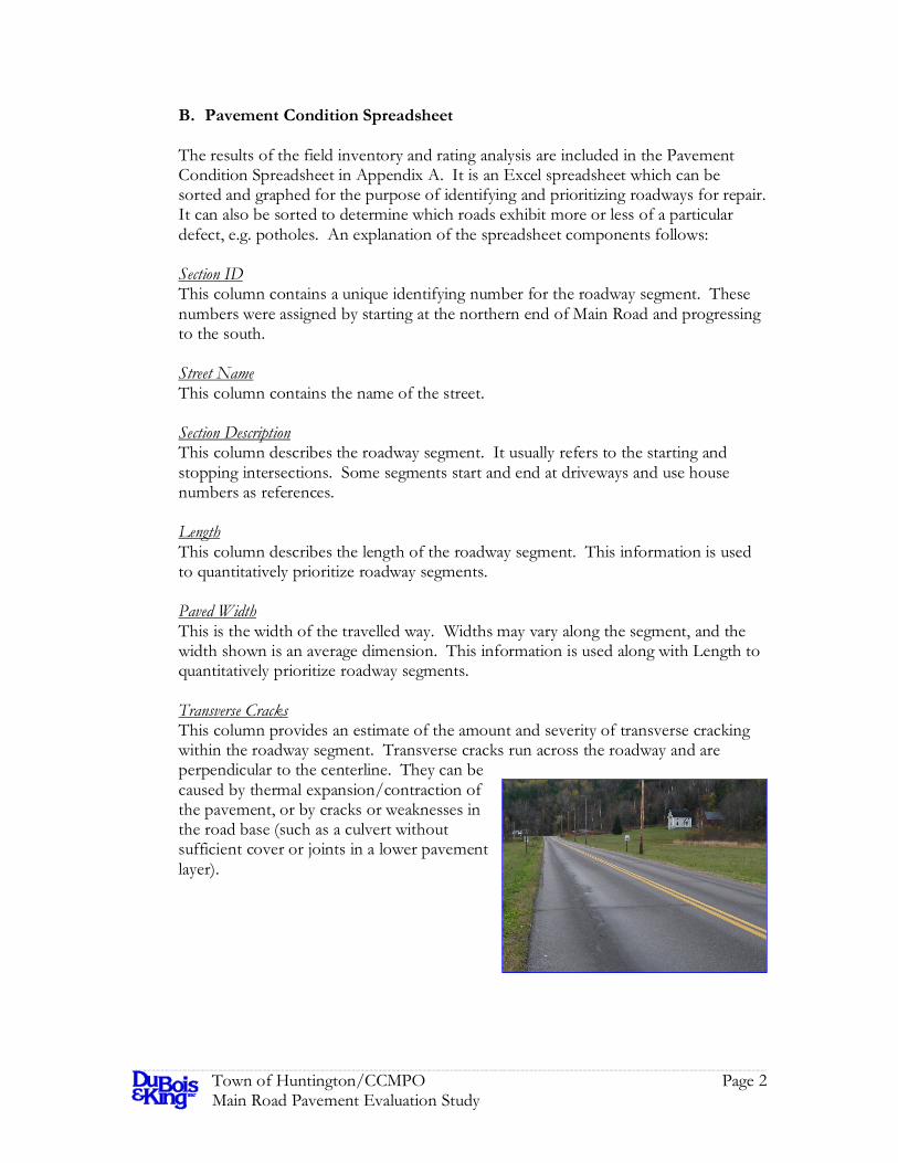
B. Pavement Condition Spreadsheet The results of the field inventory and rating analysis are included in the Pavement Condition Spreadsheet in Appendix A. It is an Excel spreadsheet which can be sorted and graphed for the purpose of identifying and prioritizing roadways for repair. It can also be sorted to determine which roads exhibit more or less of a particular defect, e.g. potholes. An explanation of the spreadsheet components follows: Section ID This column contains a unique identifying number for the roadway segment. These numbers were assigned by starting at the northern end of Main Road and progressing to the south. Street Name This column contains the name of the street. Section Description This column describes the roadway segment. It usually refers to the starting and stopping intersections. Some segments start and end at driveways and use house numbers as references. Length This column describes the length of the roadway segment. This information is used to quantitatively prioritize roadway segments. Paved Width This is the width of the travelled way. Widths may vary along the segment, and the width shown is an average dimension. This information is used along with Length to quantitatively prioritize roadway segments. Transverse Cracks This column provides an estimate of the amount and severity of transverse cracking within the roadway segment. Transverse cracks run across the roadway and are perpendicular to the centerline. They can be caused by thermal expansion/contraction of the pavement, or by cracks or weaknesses in the road base (such as a culvert without sufficient cover or joints in a lower pavement layer).

Town of Huntington/CCMPO Page 3 Main Road Pavement Evaluation Study
Longitudinal Cracks This column provides an estimate of the amount and severity of longitudinal cracking within the roadway segment. Longitudinal cracks are cracks that run along the roadway parallel to the centerline. They can be caused by improperly constructed joints or by vehicle loading. Alligator Cracks This column provides an estimate of the amount and severity of alligator cracking within the roadway segment. Alligator cracks resemble the skin of an alligator, are formed by the intersection of transverse and longitudinal cracks, and are caused by vehicle loading. Alligator cracking is a sign that the road base is not strong enough to support the vehicle traffic, and is often associated with excess water in the base materials. Shrinkage Cracks This column provides an estimate of the amount and severity of shrinkage cracks within the roadway segment. Shrinkage cracks are formed when the binder material in bituminous concrete pavement breaks down over time and separates from the adjacent pavement. These cracks are due to forces inside the pavement, not loading, and generally form blocks that are several feet across. Shrinkage cracks are usually associated with older pavement that has weakened due to exposure to the elements. Rutting This column provides an estimate of the amount and severity of rutting within the roadway segment. Ruts are deformations in the roadway where the pavement surface is depressed below that of the adjacent pavement. Ruts run parallel to the centerline and are generally caused by compaction of

Town of Huntington/CCMPO Page 4 Main Road Pavement Evaluation Study
the pavement/base materials or by the lateral displacement (shoving) of the base materials. Corrugations This column provides an estimate of the amount and severity of corrugations within the roadway segment. Corrugations are a washboard type surface with closely spaced valleys and crests. On a paved road corrugations are caused by a lack of stability in the pavement layers. Raveling This column provides an estimate of the amount and severity of raveling within the roadway segment. Raveling is the disintegration of pavement due to weathering of the binder material and subsequent release of the aggregate. Moisture on the pavement can lead to increased raveling. Raveling can be localized (such as in a pothole or the edge of the roadway), or it can occur over the entire surface. Shoving or Pushing This column provides an estimate of the amount and severity of shoving and/or pushing within the roadway segment. Shoving is the lateral displacement of pavement do to vehicle loading. Pushing is similar but is usually in the longitudinal direction. These defects occur because of weaknesses in the pavement, weaknesses in the joint between pavement layers or weakness in the base materials. Pot Holes This column provides an estimate of the amount and severity of potholes within the roadway segment. Potholes are holes in the pavement and usually form in areas where other pavement defects have weakened the pavement. They can form in areas where the base materials have a defect, such as a large stone, or in areas where the pavement layers contain defects. Excess Asphalt This column provides an estimate of the amount and severity of excess asphalt within the roadway segment. Excess asphalt, also known as bleeding, is when the asphalt binding material rises to the surface of the pavement. It is indicative of too high an asphalt content in the pavement mixture. Polished Aggregate This column provides an estimate of the amount and severity of aggregate polishing. Aggregate polishing is when the aggregate in the surface of the pavement has worn smooth over time. This is usually due to soft aggregate material or the use of aggregate that has smooth surfaces.

Town of Huntington/CCMPO Page 5 Main Road Pavement Evaluation Study
Deficient Drainage This column provides an estimate of the extent and severity of drainage problems within the roadway segment. It includes the ability of water to drain from the road surface as well as the ability of the surrounding area to drain water away from the roadway. Standing water, ditches, erosion, culverts and slopes were all considered as part of this metric. Water is a contributing factor to many of the other pavement defects, and saturated base materials can severely impact a road’s ability to carry vehicle loads. Overall Ride Quality This column provides an estimate of the ride quality. Ride quality is the “feel” of the road, and is affected by bumps, ruts, potholes and other pavement defects. Sum of Defects This column is the arithmetic sum of the previous thirteen columns (Transverse Cracks through Overall Ride Quality). This value is used to compute the Condition Rating and is also used to compute the Sum of Defects x Area column. Condition Rating This column is a representation of the pavement condition. It is computed by subtracting the Sum of Defects from 100. Roads that score high values are in very good condition, and roads with lower values are in poorer condition. Area This column provides the product of the Length and Paved Width columns. This number is multiplied by the Sum of Defects column in order to quantitatively prioritize roadway segments. Area x Sum of Defects This column is the product of the Area column and the Sum of Defects column. It is intended to be used as a quantitative measurement of roadway conditions and importance in order to prioritize roadway maintenance or improvements. The area (length) of the roadway segment is used as a proxy for the importance of the roadway segment.

Town of Huntington/CCMPO Page 6 Main Road Pavement Evaluation Study
III. GEOTECHNICAL INVESTIGATION
A. Field Investigation and Results
Geotechnical borings were conducted on October 10th and 11th , 2011. A total of 35 borings were conducted, with 27 using a solid auger and 8 using a split spoon. These borings were located approximately ¼ mile apart and alternated between lanes. Locations were picked to optimize sight distance to help ensure the safety of the workers and the travelling public. Two marked boring locations were determined to be too close to underground fiber optics lines and were therefore not used. Solid auger borings were conducted to a depth of 5 feet with the exception of two where refusal occurred at a shallower depth. Split spoon sampling was conducted to a depth of approximately 6’-8”. Soil information was recorded on the boring logs. Six of the split spoon samples were further analyzed for grain size. The geotechnical investigation indicated that the existing pavement was consistently 8 inches deep at the sampled locations. The majority of locations had between 3 and 5 feet of sandy gravel below the pavement. Sand and silty sand was generally located below the gravel layer. Two locations refused the auger at less than 5 feet, with one refusing at 4 feet and one refusing at 2.5 feet. No groundwater was observed in the borings, although the soil was moist and/or damp. Sieve testing was conducted on 6 split spoon samples. Three samples were taken from the soil strata immediately below the pavement (between 8” and 3’ deep), and three samples were taken from the samples collected deeper than 3 feet. The results of the sieve analysis were compared to VTrans Specifications 704.04A Gravel for Subbase and 704.05A Crushed Gravel for Subbase. None of the samples met the specified grain size distribution; the samples had more fine particles than allowed in the specification. Boring logs and laboratory results can be found in Appendix B. B. Evaluation and Recommendations The geotechnical investigation indicated that the pavement thickness was fairly uniform in the locations that were bored. Eight inches of pavement is most likely the result of the roadway being overlaid with new pavement multiple times since the original pavement layers were placed. Some variation in thickness is to be expected, especially in areas such as corners or areas with insufficient drainage where additional pavement may have been used to raise or smooth areas where the roadway may have rutted, shoved or otherwise lost its design profile. The presence of multiple pavement layers is also suggested by the relatively high occurrence of transverse cracks in some areas without obvious transverse faults such as culverts. While some degree of transverse cracking is to be expected on any road due to thermal forces, the close spacing of some transverse cracking suggests that they are reflections of cracks that formed in earlier pavement layers. A general rule of

Town of Huntington/CCMPO Page 7 Main Road Pavement Evaluation Study
thumb, found in the VTrans Pavement Design Guide as well as in other pavement references, is that cracks tend to work their way through newly paved surfaces at a rate of approximately 1 inch per year. Sometimes this reflective cracking can occur faster. If a cracked surface is simply overlaid with a 2 inch pavement layer, cracks in the same location as the existing cracks can be expected to appear within a 1-3 year period. In order to avoid this it is necessary to remove the cracks and other subsurface faults to the highest degree possible. The materials revealed by the geotechnical borings appear to have performed well over time. The tested materials contain more fines than allowed by the specifications. However, these fines are silt, not clay, and the roadbase is fairly well protected from infiltrating water due to the Town’s crack sealing activities. Coupled with the fact that much of the roadway is located above the water table, thereby reducing the occurrence of frost heaving in the roadway, it can be concluded that the existing gravel and sand in the roadbase are acceptable and should remain.
IV. OTHER CONSIDERATIONS
During discussions with the Town, several minor topics related to roadways came up. These, in addition to some items that were observed in the course of the field investigations, have been addressed in the following sections.
A. Guard Rails There is considerable variety in the condition and placement of guard rails (and bridge rails) in Huntington. Although a comprehensive inventory and analysis was not performed as part of this study, several issues were noted which should be addressed as part of the Town’s maintenance program.
Some rails were observed that were too low in relation to the edge of pavement according to current VTrans standards. This often is the result of repaving the roadway without adjusting the guard rails. Cable guard rail systems were observed that were in disrepair. Additionally, the rail systems on some of the bridges were not up to current standards. It is recognized that the bridges they are mounted on are older, and it is recommended that the bridge rail systems be upgraded at the time of bridge replacement. D&K’s discussion with the Town indicated that $10,000 is budgeted each year for the purposes of upgrading/maintaining guard rails. If applied conscientiously each year, this should allow the Town to repair damaged sections and adjust the elevations of other sections as needed. Large scale improvements such as replacing an entire run of obsolete guard rail may exceed this budget and should be included in the overall costs of roadway improvements.

Town of Huntington/CCMPO Page 8 Main Road Pavement Evaluation Study
B. Ditching, Culverts and Drainage Water poses one of the greatest threats to roads. It can erode surfaces and shoulders, it can saturate the base materials and diminish their strength, and it can create hazardous slippery conditions on the surface. For these reasons, as well as for water quality and environmental reasons, it is important that water be appropriately drained away from roadways. The alligator cracking found on many roads is often associated with saturated base materials. Not surprisingly, areas with alligator cracking often lacked ditches or other means of drainage. Ditches should be established and regularly maintained along all roadway segments in order to maintain or improve the service life of the road. In areas where open ditches are impractical due to surface constraints, subsurface drainage solutions such as subbase drains should be considered. Existing road culverts were generally in good shape and appeared to be adequately sized. Some 15” cross culverts were found, and these usually had in excess of 5 feet of cover. Although these culverts appeared to be in good shape, and capable of handling current storm flows, it is recommended that they be excavated and replaced during the course of road repairs. Replacing the culverts at that time will help to ensure that the life cycle of the culvert and the overlying roadway coincide to the degree possible and will reduce the need to disrupt the road base by trenching to replace the culverts at a later date. Care should be taken to place and compact materials over the replaced culverts so that a depression or transverse crack is not created. One culvert just north of Moody Road has separated on the western edge of the roadway. This has resulted in some erosion of the shoulder. Discussions with the Town indicated that this is a known problem. Several areas in which drainage conditions affected the roadway were observed. Three basic situations were observed: areas where wetlands or standing water were adjacent to the road; areas in which lawns or ledge prevented an adequate ditch from being maintained; and the undefined drainage paths found in the Lower Village near Beaudry’s Store. Some areas adjacent to wetlands showed longitudinal cracking which indicated that the road base was too weak to handle traffic loads at the time of cracking. This may
Town of Huntington/CCMPO Page 9 Main Road Pavement Evaluation Study
be a problem that varies as the water table fluctuates, and materials may have consolidated since the crack formed and the base could now be strong enough to resist cracking. The Lower Village represents a fairly large impervious area that lacks well defined drainage paths. There are many buildings and parking areas in close proximity to the road and a limited storm drain system. In order to define drainage paths in this urban environment it is recommended that curbs and storm drains be installed within the limits of the Lower Village.
C. Driveway Aprons
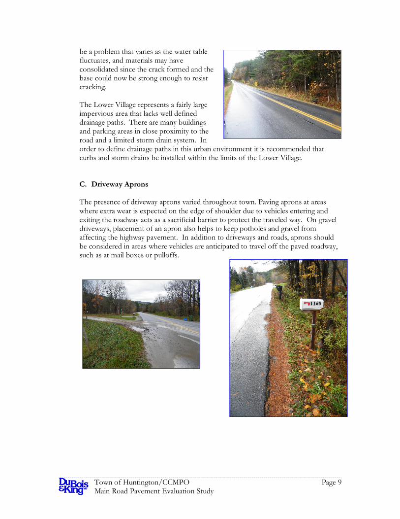
The presence of driveway aprons varied throughout town. Paving aprons at areas where extra wear is expected on the edge of shoulder due to vehicles entering and exiting the roadway acts as a sacrificial barrier to protect the traveled way. On gravel driveways, placement of an apron also helps to keep potholes and gravel from affecting the highway pavement. In addition to driveways and roads, aprons should be considered in areas where vehicles are anticipated to travel off the paved roadway, such as at mail boxes or pulloffs.

Town of Huntington/CCMPO Page 10 Main Road Pavement Evaluation Study
V. MAINTENANCE PRACTICES It is often said that an ounce of protection is worth a pound of cure. This holds true for roads; maintaining an existing road can help delay or prevent the need for expensive repairs or reconstruction. Three maintenance practices that will enhance the life of a roadway are:
ditching, removing roadside berms, and crack sealing.
Damage to roadways largely occurs due to two factors: traffic loading and environmental factors. Friction from tires will wear away the surface of the road over time, and vehicles heavier than what the road will support can cause rutting or other damage. In order to reduce damage to the roads from environmental conditions it is very important to keep the water out of the road base materials. Water that infiltrates into the road base can reduce its strength, freeze and cause frost damage, and can erode small particles out of the roadway, causing the road to settle unevenly. Ditches should be cleaned regularly and be of sufficient slope and geometry to carry stormwater and seeping groundwater away efficiently. Care should be taken to avoid velocities that will erode the ditch, and erosion matting and stone lining should be used in steeper areas. Winter sand berms should be removed at regular intervals in order to allow water to flow into the ditches rather than along the roadway surface. Cracks in the roadway allow water to seep in. This can cause the finer particles in the base to move, either through erosion, or through the pumping action that occurs when traffic depresses the pavement adjacent to a crack. Over time this loss of fines can create depressions that affect the smoothness of the ride, or even allow the base materials and pavement to slide. Cracks should be sealed with bituminous materials, and for very large cracks the pavement should be sawcut and patched. Generally speaking, these maintenance strategies are already in place in Huntington. Annual crack sealing is performed and has helped to stop water from infiltrating the cracks and making conditions worse. Ditch lines were generally clear, although it was apparent that some had been cleaned recently and others were approaching the time when they need to be cleaned. Increasing the frequency of ditch cleaning may provide some benefit, but as damage from saturated road base materials was largely observed in areas without adequate ditches, a better strategy may be to add ditches in areas that lack them. In some areas ledge prevents ditching; removing the ledge would be a one time investment that would result in better drainage patterns. Some areas did have bermed material that prevented water from draining from the roadway into the ditch. One location where this was observed was just north of Camel’s Hump Road. Ensuring that shoulders are free from bermed material will help protect the roadway and shoulder from erosion caused by water flowing alongside the pavement.

Town of Huntington/CCMPO Page 11 Main Road Pavement Evaluation Study
VI. REPAIR STRATEGIES
Choosing the proper repair technique will help to ensure that the best performance over time for the money spent will be achieved. If a technique that doesn’t address the root causes of the pavement performance issues is chosen, the improvement to the roadway will be short lived and repairs will be required again in a short time frame. On the other hand, using a technique that is far in excess of the required repair needs will result in good performance, but at a cost higher than is required. Four techniques are considered for paved roadways in this report. They are:
overlay, coldplane and resurface, reclaim and resurface, and total reconstruction
These techniques should be used after or in conjunction with improvements to roadway drainage in order to avoid damage from water. The addition of sufficient gravel to the shoulders to support the edges of the pavement and to prevent tires from dropping off the edge should be included in all repairs. One technique is the simple overlay. New pavement is placed over the existing pavement, and then the shoulders are brought up to the new pavement level with gravel. This technique is fast, but will not address any structural defects in the roadbase and changes the road surface in relation to adjacent properties. It would be necessary to build up cross road and driveway approaches in order to maintain a smooth transition onto Main Road. Cold planning and resurfacing involves using a milling machine to remove the top surface of existing pavement and then replacing the removed material with a new layer of pavement. This is the second least expensive and second fastest technique. This technique is appropriate when the surface materials have degraded, but when the base and subbase materials provide adequate support and frost resistance. This technique should not be used in areas with significant rutting or shoving because the flexible pavement will just conform to the existing failed base contours in short order. It should also not be used in areas where cracks in the existing pavement extend deeper than the surface will be milled. Reclaiming and resurfacing involves using a reclaiming machine to grind up and mix the pavement and base materials together before compaction. A new pavement surface is then placed. The reclamation process usually results in a thicker layer of material than existed previously due to the differences in compaction from the original construction and the placement of the new pavement surface. This change in height requires work on the approaches similar to that required for an overlay. This technique is appropriate where the pavement surface is degraded and the base and subbase materials are of sufficient quality to provide adequate support and frost

Town of Huntington/CCMPO Page 12 Main Road Pavement Evaluation Study
resistance, but need to be reshaped. This technique should not be used in places where the base and subbase materials are susceptible to frost damage. Total reconstruction involves removing the old roadway materials by excavation, and placing new base materials before adding a new pavement surface. This technique results in the highest quality roadway. It should not be used in areas where the existing base materials possess the geometry, frost resistance and strength to support traffic loads. This technique is the most expensive and takes the longest of the four considered techniques. A table showing a summary of repair techniques and costs is shown below. A more detailed breakdown can be found in Appendix C. Main Road has both quality base materials in fairly good shape and a thick layer of existing pavement that has deep cracks in it. Due to the condition of the road base it is not necessary or suggested to reconstruct the roadway, with the possible exception of areas immediately adjacent to wetlands where longitudinal cracking and shoving/rutting can be observed. Overlaying and cold planning/resurfacing are not generally recommended as these techniques would only hide the cracks for a short time. Therefore, it is recommended that the roadway be reclaimed to a depth that would break up the existing pavement layers, and then surfaced with both a base and wearing course of pavement.
VII. SHORT-TERM RECOMMENDATIONS The different repair techniques and existing conditions were analyzed in order to determine the appropriate technique for each roadway segment. Prices were frozen at today’s levels with the assumption that revenues and prices will increase proportionally. A plan was developed that will result in repairing approximately 1.2 miles of roadway per year. The schedule would provide for improving the entire road every 8 years based upon the length of Main Road. A table showing the proposed short term (5 year) repair schedule is shown below. A copy of the table is
Table 1) Cost of Repair Technique per 1000 Feet of Length (based upon a paved
width of 24 feet) Technique Cost Overlay $26,500 Cold Plane and Resurface $34,400 Reclaim $41,300 Reconstruct $146,000

Town of Huntington/CCMPO Page 13 Main Road Pavement Evaluation Study
also found in Appendix D. It should be noted that all costs presented are estimated construction costs, and do not reflect any costs for drainage improvements, design, permitting, guard rails or construction inspection.
Table 2) Proposed Short Term Repair Schedule
Year ID Road From/To Length (miles) Overlay?
Coldplane and Overlay? Reclaim? Reconstruct?
1 4 Main Road Windy Pines Drive to Blackbird Swale 0.710 X
1 2 Main Road Sherman Hollow to Lavalle Drive 0.498 X
2 17 Main Road Weaver Road to 9283 Main Road 0.590 X
2 18 Main Road 9283 Main Road to Buel's Gore Line 0.432 X
3 5 Main Road Blackbird Swale to Cummings Drive 0.792 X
3 8 Main Road
Knight's Notch to Pleasant Mount Farm (4501 Main Rd) 0.575 X
4 9 Main Road
Pleasant Mount Farm (4501 Main Rd) to Trapp Road 0.699 X
4 7 Main Road Rocque Drive to Knight's Notch 0.532 X
5 6 Main Road Cummings Drive to Rocque Drive 0.523 X
5 12 Main Road Maple Drive to joint @ 6565 Main Road 0.534 X
VIII. LONG-TERM RECOMMENDATIONS Continuing the methodology described in the preceding section, a schedule for long term (6-20 years in the future) was developed. It is not shown here, but can be found in Appendix E due to its length. A budget has been prepared showing the costs used to prepare the schedule. It should be noted that this schedule and budget only consider paved roadway surface repair, and are in today’s dollars with no adjustment. It does not include work or costs related to guard rails, drainage improvements, signs, pavement markings, bridges, equipment or personnel, nor does it include costs for engineering, permitting or construction inspection. The table below shows the proposed repair budget.

Town of Huntington/CCMPO Page 14 Main Road Pavement Evaluation Study
Table 3) Proposed Repair Budget Year Cost Miles
1 $263,453 1.208 2 $142,968 1.022 3 $297,980 1.366 4 $268,450 1.231
5 $230,619 1.058 6 $255,110 1.170 7 $308,924 1.417 8 $219,438 1.208 9 $185,588 1.022
10 $248,196 1.366 11 $223,600 1.231 12 $192,090 1.058 13 $212,489 1.170 14 $257,312 1.417
15 $257,312 1.417 16 $238,977 1.316 17 $219,438 1.208 18 $185,588 1.022 19 $248,196 1.366 20 $223,600 1.231
It is recognized that these values are in excess of the $100 thousand typically allocated for repairing pavement in Huntington, and will require grant or other funding to achieve the proposed schedule. This schedule was developed based upon an improvement cycle length of 8 years. The majority of observed defects are at least partially attributable to defects in underlying pavement layers or areas with deficient drainage. Once these problems are dealt with either through reclamation of the roadway, or improvements to ditches, it is possible that a longer resurfacing interval would be appropriate. If structural defects in the roadway can be eliminated, and water kept out of the roadbase, it should be possible to extend the life of the pavement and increase the improvement cycle length.

Town of Huntington/CCMPO Page 15 Main Road Pavement Evaluation Study
IX. CONCLUSIONS In general, Main Road is in fairly good shape. There are some localized areas with insufficient drainage, but the vast majority of the road base is of adequate material and in good condition. Some portions of the road have significant cracks, and many of these appear to be reflections of cracking that has occurred in lower pavement layers. Removing the cracks in their entirety by reclaiming the roadway will result in a smoother riding road that offers fewer chances for water to infiltrate the roadbase and cause damage. Reclaiming the roadway will provide a stable platform for new pavement, and will provide a longer lasting product than simply overlaying the existing pavement. Overlaying and cold planing/resurfacing are generally not recommended for Main Road at this time due to the existing pavement defects and the presence of a thick pavement layer. Without the removal of the underlying pavement and associated defects, new surfaces will quickly exhibit defects in the same locations. However, overlaying or cold planning/resurfacing is recommended on the southernmost segments of Main Road that have already been reclaimed since the underlying pavement defects have already been addressed. Full depth reconstruction is also generally not recommended for Main Road due to the reasonably good condition of the road base and the presence of adequate base materials. High degrees of rutting or shoving would indicate that the roadbase lacks the geometric and structural properties required to properly support a roadway, and few defects of this nature were observed. One area in which full depth reconstruction would be recommended is in the Lower Village. Performing a full depth reconstruction at the same time that a storm drain system was installed would help to minimize the overall excavation required and would eliminate the need to trench reclaimed areas for drainage pipes. Elimination of trenching will help ensure that the road base is homogenous and reduce the likelihood of pavement damage in areas where base materials change. Through a combination of reclaiming, cold planning/resurfacing and full depth reconstruction it will be possible to rehabilitate the entire length of Main Road over an 8 year period. After this initial period the road surface can simply be cold planed/resurfaced as needed. Timely crack sealing, ditching and other maintenance activities will help preserve the road base, and cold planning distressed pavements prior to resurfacing will help eliminate reflective cracking that negatively affects the roadway. Future maintenance costs can be reduced by ensuring that Main Road is built upon a solid base that is well drained, and by addressing surface problems before they have a chance to damage the underlying structural layers.

Appendix A
Pavement Condition Spreadsheet

JOB Randolph, VT Bedford, NH SHEET NO. OF Williston, VT Springfield, CALCULATED BY: DATE:
Engineering Planning Development Management CHECKED BY: DATE:
SCALE:
Section ID = Will assign an arbitrary number to each road section and display on map. Will just start in one corner and number sections until done.Street Name Section Description Length (miles)
Paved Width (feet)
Tran
sver
se C
rack
s 0-
5
Long
itudi
nal C
rack
s 0-
5
Alli
gato
r Cra
cks
0-10
Shrin
kage
Cra
cks
0-5
Rut
ting
0-10
Cor
ruga
tion
0-5
Rav
elin
g 0-
5
Shov
ing
or P
ushi
ng 0
-10
Pot H
oles
0-1
0
Exce
ss A
spha
lt 0-
10
Polis
hed
Agg
rega
te 0
-5
Def
icie
nt D
rain
age
0-10
Ove
ral R
idin
g Q
ualit
y 0-
10
SUM
OF
DEF
ECTS
CO
ND
ITIO
N R
ATI
NG
Are
a (S
Y)
Are
a x
Sum
of d
efec
ts (s
ort
desc
endi
ng to
prio
ritiz
e se
ctio
ns)
Ove
rlay
Col
dpla
ne a
nd R
esur
face
Rec
laim
Rec
onst
ruct
Rep
air T
echn
ique
Cos
t per
100
0 ft
Estim
ated
Rep
air C
ost
Rep
air Y
ear
Res
urfa
ce Y
ear 1
Res
urfa
ce Y
ear 2
1 Main Road Richmond Town Line to Sheman Hollow 0.464 24 3 3 3 2 3 0 2 2 3 0 1 3 4 29 71 6539 189621 X $41,300 $101,268 8 16 24
2 Main Road Sherman Hollow to Lavalle Drive 0.498 24 2 4 4 2 5 0 2 4 3 0 1 5 4 36 64 7011 252384 X $41,300 $108,578 1 9 17
3 Main Road Lavalle Drive to Windy Pines Drive 0.451 24 3 4 3 2 4 0 1 4 4 0 1 4 3 33 67 6349 209528 X $41,300 $98,335 7 15 23
4 Main Road Windy Pines Drive to Blackbird Swale 0.710 24 3 3 2 2 3 0 1 3 2 0 1 4 4 28 72 10000 280000 X $41,300 $154,875 1 9 17
5 Main Road Blackbird Swale to Cummings Drive 0.792 24 3 3 4 3 3 0 2 3 0 0 1 5 3 30 70 11149 334480 X $41,300 $172,675 3 11 19
6 Main Road Cummings Drive to Rocque Drive 0.523 24 3 4 3 4 3 0 2 2 2 0 2 4 4 33 67 7368 243144 X $41,300 $114,112 5 13 21
7 Main Road Rocque Drive to Knight's Notch 0.532 24 4 3 4 4 3 0 2 3 2 0 1 3 4 33 67 7488 247104 X $41,300 $115,970 4 12 20
8 Main Road Knight's Notch to Pleasant Mount Farm (4501 Main Rd) 0.575 24 4 3 4 4 3 0 1 2 1 0 1 4 4 31 69 8091 250811 X $41,300 $125,304 3 11 19
9 Main Road Pleasant Mount Farm (4501 Main Rd) to Trapp Road 0.699 24 3 2 2 4 3 0 1 2 2 0 1 4 4 28 72 9845 275669 X $41,300 $152,480 4 12 20
10 Main Road Trapp Road to Shaker Mountain Road 0.401 24 3 2 2 4 2 0 1 2 2 0 1 2 4 25 75 5651 141267 X $41,300 $87,515 7 15 23
11 Main Road Shaker Mountain Road to Maple Drive 0.435 243 3 3 3 2 0 2 2 1 0 1 3 4 27 73 6131 165528
X $41,300 $94,949 8 16 24
12 Main Road Maple Drive to joint @ 6565 Main Road 0.534 24 2 3 3 4 3 0 2 2 4 0 1 4 4 32 68 7523 240725 X $41,300 $116,507 5 13 21
13 Main Road joint @ 6565 Main Road to Moody Road 0.603 24 2 3 3 3 3 0 2 2 2 0 1 3 3 27 73 8491 229248 X $41,300 $131,499 6 14 22
14 Main Road Moody Road to 7652 Main Road 0.567 24 2 3 4 3 3 0 2 3 2 0 1 4 3 30 70 7981 239440 X $41,300 $123,611 6 14 22
15 Main Road 7652 Main Road to Carse Road 0.416 24 2 3 3 3 2 0 1 2 1 0 1 4 3 25 75 5856 146400 X $41,300 $90,695 8 16 24
16 Main Road Carse Road to Weaver Road 0.564 24 2 3 3 3 2 0 1 2 3 0 1 3 3 26 74 7947 206613 X $41,300 $123,074 7 15 23
17 Main Road Weaver Road to 9283 Main Road 0.590 24 0 1 1 0 2 0 1 0 1 0 1 2 2 11 89 8307 91373 X $26,500 $82,548 2 10 18
18 Main Road 9283 Main Road to Buel's Gore Line 0.432 24 1 1 1 0 2 0 1 1 1 0 1 2 2 13 87 6080 79040 X $26,500 $60,420 2 10 18
Road Analysis

Appendix B
Geotechnical Data Sheets

MIKE’S BORING & CORING LLC. P.O. Box 75 East Barre, VT 05649
To: John Merrifield DuBois & King, Inc. P.O. Box 339 Randolph, VT 05060
Date 10-10-11- 10-11-11
Job Name/Site Road Reconstruction/Huntington, VT
Job Number 11092
Crew Dave and Shawn
Inspector John
HOLE
# OFFSET STATIC
LEVEL SOILS AUGER
REFUSAL (Feet)
DEPTH (Feet)
B-1 N/A N/A 0’-8” Pavement
8”-5’ Brown medium sandy gravel
5’
B-2 N/A N/A 0’-8” Pavement
8”-5’ Brown medium sandy gravel
5’
B-3 N/A N/A 0’-8” Pavement
8”-3’ Brown medium sandy gravel
3’-5’ Grayish brown silty sand with medium gravel
5’
B-5 N/A N/A 0’-8” Pavement
8”-5’ Brown medium sandy gravel
5
B-6 N/A N/A 0’-8” Pavement
8”-3’ Brown medium sandy gravel
3’-5’ Brown fine silty sand
5’
B-7 N/A N/A 0’-8” Pavement
8”-5’ Brown medium sandy gravel
5’
B-9 N/A N/A 0’-8” Pavement
8”-5’ Brown medium sandy gravel
5’
B-10 N/A N/A 0’-8” Pavement
8”-5’ Brown medium sandy gravel
5’
B-11 N/A N/A 0’-8” Pavement
8”-5’ Brown medium sandy gravel
5’
B-12 N/A N/A 0’-8” Pavement
8”-5’ Brown medium sandy gravel
5’
B-14 N/A NA 0’-8” Pavement
8”-5’ Brown medium sandy gravel
5’

HOLE
# OFFSET STATIC
LEVEL SOILS AUGER
REFUSAL (Feet)
DEPTH (Feet)
B-15 N/A N/A 0’-8” Pavement
8”-4’ Brown medium sandy gravel
4’-5’ Brown fine sand
5’
B-16 N/A N/A 0’-8” Pavement
8”-3’ Brown medium sandy gravel
3’-5’ Brown fine silty sand
5’
B-18 N/A N/A 0’-8” Pavement
8”-5’ Brown medium sandy gravel
5’
B-19 N/A N/A 0’-8” Pavement
8”-3’ Brown medium sandy gravel
3’-5’ Brown fine silty sand
5’
B-20 N/A N/A 0’-8” Pavement
8”-3’ Brown medium gravel
3’-5’ Brown fine silty sand
5’
B-21 N/A N/A To close to fiber line in roadway, did not drill
B-23 N/A N/A 0’-8” Pavement
8”-5’ Brown medium sandy gravel
5’
B-24 N/A N/A 0’-8” Pavement
8”-3’ Brown medium sandy gravel
3’-5’ Brown medium fine sand
5’
B-25 N/A N/A 0’-8” Pavement
8”-3’ Brown medium sandy gravel
3’-5’ Brown medium fine sand
5’
B-27 N/A N/A 0’-8” Pavement
8”-3’ Brown medium sandy gravel
3’-5’ Brown silty fine sand
5’
B-28 N/A N/A 0’-8” Pavement
8”-3’ Brown medium sandy gravel
3’-5’ Brown silty fine sand
5’
B-29 N/A N/A Did not drill Fiber line to close
B-30 N/A N/A 0’-8” Pavement
8”-3’ Brown medium sandy gravel
5’

HOLE
# OFFSET STATIC
LEVEL SOILS AUGER
REFUSAL (Feet)
DEPTH (Feet)
3’-5’ Brown silty fine sand
B-32 N/A N/A 0’-8” Pavement
8”-3’ Brown medium sandy gravel
3’-4’ Brown medium fine sand
4’ 4’
B-33 N/A N/A 0’-8” Pavement
8”-2.5’ Brown fine sand some gravel
Refusal on large stone
2.5’ 2.5’
B-34 N/A N/A 0’-8” Pavement
8”-3’ Brown medium sandy gravel
3’-5’ Brown silty fine sand
5’
B-35 N/A N/A 0’-8” Pavement
8”-3’ Brown medium sandy gravel
3’-5’ Brown silty fine sand
5’
B-A N/A N/A 0’-8” Pavement
8”-5’ Brown medium sandy gravel
*Should have been first boring but was missed**
5’
TOTAL FOOTAGE: 126.5’
AUGERS USED: Solid

MIKE’S BORING & CORING LLC. PO Box 75 East Barre, Vermont 05649 802 476-5073
TO: John D. Merrifield
DuBois & King Inc. P.O. Box 339 Randolph, VT 05060
PROJECT NAME: LOCATION: MBC JOB #:
Road Reconstruction Huntington, VT 11092
SHEET: DATE: HOLE #: LINE & STA. OFFSET:
1 10-10-11 SB-4
Ground Water Observations none at _0 _ hours
Augers-Size I.D. 3.25” Split Spoon 2” Hammer Wt. 140# Hammer Fall 30"
Surface Elevation: Date Started: Date Completed: Boring Foreman: Inspector: Soils Engineer:
10-10-11 10-10-11 Dave Johnson
LOCATION OF BORING: As shown
Sample Depths
From/To (Feet)
Type of
Sample
Blows per 6" on Sampler
Moisture Density or Consist.
Strata Change
Elev.
Soil Identification Sample No. Pen. Rec. Inches Inches
9”-2’9” Dry 35/30/18/9 Moist 9” Pavement into brown medium sandy gravel 1 24 14
2’9”-4’9” Dry 6/5/5/4 Moist/damp 3’ Brown medium sandy gravel into brown fine silty sands
2 24 18
4’9”-6’9” Dry 4/4/10/15 Damp Brown fine silty sand with layer of medium gravel
3 24 14
Ground Surface to 4’9” Used 3.25” augers: Then S.S. to 6’9” Earth Borings 6’9” Rock Coring Samples: 3 HOLE NUMBER SB-4

MIKE’S BORING & CORING LLC. PO Box 75 East Barre, Vermont 05649 802 476-5073
TO: John D. Merrifield
DuBois & King Inc. P.O. Box 339 Randolph, VT 05060
PROJECT NAME: LOCATION: MBC JOB #:
Road Reconstruction Huntington, VT 11092
SHEET: DATE: HOLE #: LINE & STA. OFFSET:
2 10-10-11 SB-8
Ground Water Observations none at _0 _ hours
Augers-Size I.D. 3.25” Split Spoon 2” Hammer Wt. 140# Hammer Fall 30"
Surface Elevation: Date Started: Date Completed: Boring Foreman: Inspector: Soils Engineer:
10-10-11 10-10-11 Dave Johnson
LOCATION OF BORING: As shown
Sample Depths
From/To (Feet)
Type of
Sample
Blows per 6" on Sampler
Moisture Density or Consist.
Strata Change
Elev.
Soil Identification Sample No. Pen. Rec. Inches Inches
8”-2’8” Dry 15/35/21/15 Moist 1’ Brown medium gravel into brown fine sand 1 24 16
2’8”-4’8” Dry 10/6/5/4 Moist Brown fine sand 2 24 18
4’8”-6’8” Dry 3/2/4/5 Moist/damp 5’ Brown fine sand 3 24 20
Ground Surface to 4’8” Used 3.25” augers: Then S.S. to 6’8” Earth Borings 6’8” Rock Coring Samples: 3 HOLE NUMBER SB-8

MIKE’S BORING & CORING LLC. PO Box 75 East Barre, Vermont 05649 802 476-5073
TO: John D. Merrifield
DuBois & King Inc. P.O. Box 339 Randolph, VT 05060
PROJECT NAME: LOCATION: MBC JOB #:
Road Reconstruction Huntington, VT 11092
SHEET: DATE: HOLE #: LINE & STA. OFFSET:
3 10-10-11 SB-13
Ground Water Observations none at _0 _ hours
Augers-Size I.D. 3.25” Split Spoon 2” Hammer Wt. 140# Hammer Fall 30"
Surface Elevation: Date Started: Date Completed: Boring Foreman: Inspector: Soils Engineer:
10-10-11 10-10-11 Dave Johnson
LOCATION OF BORING: As shown
Sample Depths
From/To (Feet)
Type of
Sample
Blows per 6" on Sampler
Moisture Density or Consist.
Strata Change
Elev.
Soil Identification Sample No. Pen. Rec. Inches Inches
8”-2’8” Dry 18/28/18/20 Moist Brown medium sandy gravel 1 24 16
2’8”-4’8” Dry 17/12/9/7 Moist/damp 3.5’ Brown medium sandy gravel into brown fine sand
2 24 10
4’8”-6’8” Dry 9/7/9/16 Damp Brown fine sand 3 24 12
Ground Surface to 4’8” Used 3.25” augers: Then S.S. to 6’8” Earth Borings 6’8” Rock Coring Samples: 3 HOLE NUMBER SB-13

MIKE’S BORING & CORING LLC. PO Box 75 East Barre, Vermont 05649 802 476-5073
TO: John D. Merrifield
DuBois & King Inc. P.O. Box 339 Randolph, VT 05060
PROJECT NAME: LOCATION: MBC JOB #:
Road Reconstruction Huntington, VT 11092
SHEET: DATE: HOLE #: LINE & STA. OFFSET:
4 10-10-11 SB-17
Ground Water Observations none at _0 _ hours
Augers-Size I.D. 3.25” Split Spoon 2” Hammer Wt. 140# Hammer Fall 30"
Surface Elevation: Date Started: Date Completed: Boring Foreman: Inspector: Soils Engineer:
10-10-11 10-10-11 Dave Johnson
LOCATION OF BORING: As shown
Sample Depths
From/To (Feet)
Type of
Sample
Blows per 6" on Sampler
Moisture Density or Consist.
Strata Change
Elev.
Soil Identification Sample No. Pen. Rec. Inches Inches
8”-2’8” Dry 30/15/13/7 Moist Brown medium sandy gravel 1 24 14
2’8”-4’8” Dry 2/6/5/5 Moist/damp 3.5’ Brown medium sandy gravel into fine silty sand 2 24 18
4’8”-6’8” Dry 9/8/11/8 Damp Brown fine silty sand 3 24 12
Ground Surface to 4’8” Used 3.25” augers: Then S.S. to 6’8” Earth Borings 6’8” Rock Coring Samples: 3 HOLE NUMBER SB-17

MIKE’S BORING & CORING LLC. PO Box 75 East Barre, Vermont 05649 802 476-5073
TO: John D. Merrifield
DuBois & King Inc. P.O. Box 339 Randolph, VT 05060
PROJECT NAME: LOCATION: MBC JOB #:
Road Reconstruction Huntington, VT 11092
SHEET: DATE: HOLE #: LINE & STA. OFFSET:
5 10-10-11 SB-22
Ground Water Observations none at _0 _ hours
Augers-Size I.D. 3.25” Split Spoon 2” Hammer Wt. 140# Hammer Fall 30"
Surface Elevation: Date Started: Date Completed: Boring Foreman: Inspector: Soils Engineer:
10-10-11 10-10-11 Dave Johnson
LOCATION OF BORING: As shown
Sample Depths
From/To (Feet)
Type of
Sample
Blows per 6" on Sampler
Moisture Density or Consist.
Strata Change
Elev.
Soil Identification Sample No. Pen. Rec. Inches Inches
8”-2’8” Dry 16/17/21/16 Moist Brown medium gravel 1 24 12
2’8”-4’8” Dry 17/6/8/6 Moist/damp 3.5’ Brown medium gravel into gray silty fine sand 2 24 18
4’8”-6’8” Dry 6/13/20/28 Damp Gray silty fine sand with some medium gravel 3 24 16
Ground Surface to 4’8” Used 3.25” augers: Then S.S. to 6’8” Earth Borings 6’8” Rock Coring Samples: 3 HOLE NUMBER SB-22

MIKE’S BORING & CORING LLC. PO Box 75 East Barre, Vermont 05649 802 476-5073
TO: John D. Merrifield
DuBois & King Inc. P.O. Box 339 Randolph, VT 05060
PROJECT NAME: LOCATION: MBC JOB #:
Road Reconstruction Huntington, VT 11092
SHEET: DATE: HOLE #: LINE & STA. OFFSET:
6 10-11-11 SB-26
Ground Water Observations none at _0 _ hours
Augers-Size I.D. 3.25” Split Spoon 2” Hammer Wt. 140# Hammer Fall 30"
Surface Elevation: Date Started: Date Completed: Boring Foreman: Inspector: Soils Engineer:
10-11-11 10-11-11 Dave Johnson
LOCATION OF BORING: As shown
Sample Depths
From/To (Feet)
Type of
Sample
Blows per 6" on Sampler
Moisture Density or Consist.
Strata Change
Elev.
Soil Identification Sample No. Pen. Rec. Inches Inches
8”-2’8” Dry 16/16/10/13 Moist Brown medium gravel 1 24 18
2’8”-4’8” Dry 14/18/100 for 2”
Moist/wet 3’ Brown medium gravel into brown silty fine sand with some gravel
2 16 14
Ground Surface to 2’8” Used 3.25” augers: Then S.S. to refusal at 3’10” Earth Borings 3’10” Rock Coring Samples: 2 HOLE NUMBER SB-26

MIKE’S BORING & CORING LLC. PO Box 75 East Barre, Vermont 05649 802 476-5073
TO: John D. Merrifield
DuBois & King Inc. P.O. Box 339 Randolph, VT 05060
PROJECT NAME: LOCATION: MBC JOB #:
Road Reconstruction Huntington, VT 11092
SHEET: DATE: HOLE #: LINE & STA. OFFSET:
7 10-11-11 SB-31
Ground Water Observations none at _0 _ hours
Augers-Size I.D. 3.25” Split Spoon 2” Hammer Wt. 140# Hammer Fall 30"
Surface Elevation: Date Started: Date Completed: Boring Foreman: Inspector: Soils Engineer:
10-11-11 10-11-11 Dave Johnson
LOCATION OF BORING: As shown
Sample Depths
From/To (Feet)
Type of
Sample
Blows per 6" on Sampler
Moisture Density or Consist.
Strata Change
Elev.
Soil Identification Sample No. Pen. Rec. Inches Inches
8”-2’8” Dry 6/9/9/8 Moist 2’ Brown medium gravel into brown fine sand 1 24 14
2’8”-4’8” Dry 7/11/18/21 Moist Brown fine sand with a trace of gravel 2 24 20
4’8”-6’8” Dry 15/18/19/22 Moist Brown fine sand with a trace of gravel 3 24 14
Ground Surface to 4’8” Used 3.25” augers: Then S.S. to 6’8” Earth Borings 6’8” Rock Coring Samples: 3 HOLE NUMBER SB-31

MIKE’S BORING & CORING LLC. PO Box 75 East Barre, Vermont 05649 802 476-5073
TO: John D. Merrifield
DuBois & King Inc. P.O. Box 339 Randolph, VT 05060
PROJECT NAME: LOCATION: MBC JOB #:
Road Reconstruction Huntington, VT 11092
SHEET: DATE: HOLE #: LINE & STA. OFFSET:
8 10-11-11 SB-36
Ground Water Observations none at _0 _ hours
Augers-Size I.D. 3.25” Split Spoon 2” Hammer Wt. 140# Hammer Fall 30"
Surface Elevation: Date Started: Date Completed: Boring Foreman: Inspector: Soils Engineer:
10-11-11 10-11-11 Dave Johnson
LOCATION OF BORING: As shown
Sample Depths
From/To (Feet)
Type of
Sample
Blows per 6" on Sampler
Moisture Density or Consist.
Strata Change
Elev.
Soil Identification Sample No. Pen. Rec. Inches Inches
8”-2’8” Dry 21/25/18/9 Moist 2.5’ Brown medium gravel into brown fine sand 1 24 18
2’8”-4’8” Dry 9/8/8/6 Moist/damp 3’ Brown fine sand with some silt 2 24 16
4’8”-6’8” Dry 8/5/6/7 Moist 5’ Brown fine sand with some silt into brown medium gravel
3 24 16
Ground Surface to 4’8” Used 3.25” augers: Then S.S. to 6’8” Earth Borings 6’8” Rock Coring Samples: 3 HOLE NUMBER SB-36


Appendix C
Cost Estimate

Length 1000 ft Mill and Fill 34364 34400Paved Width 24 ft Reconstruct 145943.7 146000Shouler 2 ft Reclaim 41287.88 41300new pavement 4 in Overlay 26444 26500fill pavement 1.5 in
ReconstructionLength 1000 ftWidth 24 ftBase 6 inSubbase 12 inPavement Thicness 4 inShoulders 2 ft
Using Vtrans 2 year averaged price list 7/09-6/11 Using Vtrans 2 year averaged price list 7/09-6/11Bituminous pavement (2 layers) 1280000 lbs 640 tons 80 51200
shoulder gravel 1333.333 cf 49.38272 cy 45 2222.222crushed gravel 14000 cf 518.5185 cy 31 16074.07gravel for roadbed 28000 cf 1037.037 cy 24 24888.89
common excavation 51333.33 cf 1901.235 cy 7 13308.64clearing and grubbing 0.229568 ac 12500 2869.605mobilization 11056.34traffic control 11056.34
subtotal 132676.110% contigency13267.61total 145943.7
Mill and filllength 1000width 24thickness 1.5shoulder 2
milling 24000 sf 2666.667 sy 2.25 6000bituminous pavement 3000 cf 480000 lb 240 ton 80 19200
shoulder gravel 500 cf 18.51852 cy 45 833.3333clearing and grubbing 0.229568 ac 12500mobilization 2603.333traffic control 2603.333
subtotal 3124010% contigency 3124total 34364
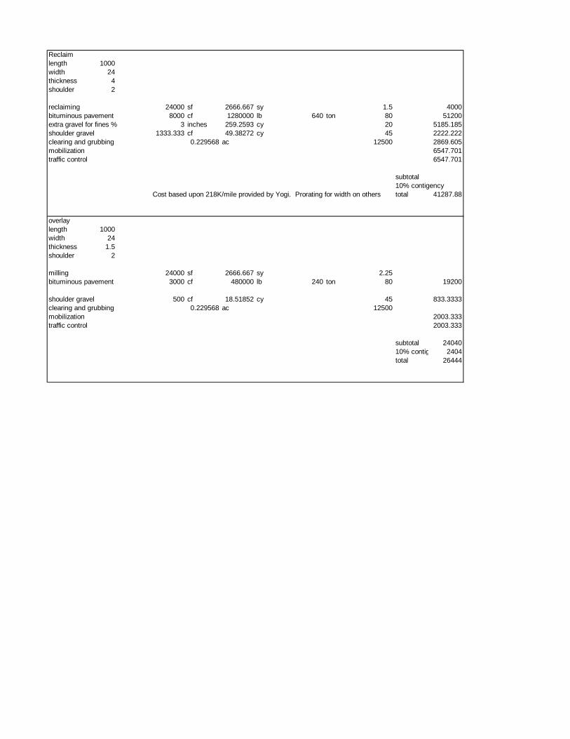
Reclaimlength 1000width 24thickness 4shoulder 2
reclaiming 24000 sf 2666.667 sy 1.5 4000bituminous pavement 8000 cf 1280000 lb 640 ton 80 51200extra gravel for fines % 3 inches 259.2593 cy 20 5185.185shoulder gravel 1333.333 cf 49.38272 cy 45 2222.222clearing and grubbing 0.229568 ac 12500 2869.605mobilization 6547.701traffic control 6547.701
subtotal10% contigency
Cost based upon 218K/mile provided by Yogi. Prorating for width on others total 41287.88
overlaylength 1000width 24thickness 1.5shoulder 2
milling 24000 sf 2666.667 sy 2.25bituminous pavement 3000 cf 480000 lb 240 ton 80 19200
shoulder gravel 500 cf 18.51852 cy 45 833.3333clearing and grubbing 0.229568 ac 12500mobilization 2003.333traffic control 2003.333
subtotal 2404010% contigency 2404total 26444

Appendix D
Short Term Repair Schedule

Year ID Road From/ToLength (miles) Overlay?
Coldplane and Overlay? Reclaim? Reconstruct?
1 4 Main Road Windy Pines Drive to Blackbird Swale 0.710 X1 2 Main Road Sherman Hollow to Lavalle Drive 0.498 X2 17 Main Road Weaver Road to 9283 Main Road 0.590 X2 18 Main Road 9283 Main Road to Buel's Gore Line 0.432 X3 5 Main Road Blackbird Swale to Cummings Drive 0.792 X
3 8 Main RoadKnight's Notch to Pleasant Mount Farm (4501 Main Rd) 0.575 X
4 9 Main RoadPleasant Mount Farm (4501 Main Rd) to Trapp Road 0.699 X
4 7 Main Road Rocque Drive to Knight's Notch 0.532 X5 6 Main Road Cummings Drive to Rocque Drive 0.523 X
5 12 Main Road Maple Drive to joint @ 6565 Main Road 0.534 X
Table 2) Proposed Short Term Repair Schedule

Appendix E
Long Term Repair Schedule

Year ID Road From/To Length Overlay?
Coldplane and Overlay? Reclaim? Reconstruct?
6 14 Main Road Moody Road to 7652 Main Road 0.567 X6 13 Main Road joint @ 6565 Main Road to Moody Road 0.603 X7 3 Main Road Lavalle Drive to Windy Pines Drive 0.451 X7 16 Main Road Carse Road to Weaver Road 0.564 X7 10 Main Road Trapp Road to Shaker Mountain Road 0.401 X8 1 Main Road Richmond Town Line to Sheman Hollow 0.464 X8 11 Main Road Shaker Mountain Road to Maple Drive 0.435 X8 15 Main Road 7652 Main Road to Carse Road 0.416 X9 4 Main Road Windy Pines Drive to Blackbird Swale 0.710 X9 2 Main Road Sherman Hollow to Lavalle Drive 0.498 X
10 17 Main Road Weaver Road to 9283 Main Road 0.590 X10 18 Main Road 9283 Main Road to Buel's Gore Line 0.432 X11 5 Main Road Blackbird Swale to Cummings Drive 0.792 X11 8 Main Road Knight's Notch to Pleasant Mount Farm (4501 Main Rd)0.575 X12 9 Main Road Pleasant Mount Farm (4501 Main Rd) to Trapp Road0.699 X12 7 Main Road Rocque Drive to Knight's Notch 0.532 X13 6 Main Road Cummings Drive to Rocque Drive 0.523 X13 12 Main Road Maple Drive to joint @ 6565 Main Road 0.534 X14 14 Main Road Moody Road to 7652 Main Road 0.567 X14 13 Main Road joint @ 6565 Main Road to Moody Road 0.603 X15 3 Main Road Lavalle Drive to Windy Pines Drive 0.451 X15 16 Main Road Carse Road to Weaver Road 0.564 X15 10 Main Road Trapp Road to Shaker Mountain Road 0.401 X16 1 Main Road Richmond Town Line to Sheman Hollow 0.464 X16 11 Main Road Shaker Mountain Road to Maple Drive 0.435 X16 15 Main Road 7652 Main Road to Carse Road 0.416 X17 4 Main Road Windy Pines Drive to Blackbird Swale 0.710 X17 2 Main Road Sherman Hollow to Lavalle Drive 0.498 X18 17 Main Road Weaver Road to 9283 Main Road 0.590 X18 18 Main Road 9283 Main Road to Buel's Gore Line 0.432 X19 5 Main Road Blackbird Swale to Cummings Drive 0.792 X19 8 Main Road Knight's Notch to Pleasant Mount Farm (4501 Main Rd)0.575 X20 9 Main Road Pleasant Mount Farm (4501 Main Rd) to Trapp Road0.699 X20 7 Main Road Rocque Drive to Knight's Notch 0.532 X
Proposed Long Term Repair Schedule

Appendix F
Roadway Map
