magnetic brake systems
TRANSCRIPT

MAGNETIC BRAKE SYSTEMS
A DIVISION OF TECHNICAL FILM SYSTEMS, INC.
4650 Calle Quetzal • Camarillo, CA 93012-9101 • Phone: 805.383.6903
E-Mail: [email protected] • Website: www.magbrakesystems.com
DYNAMOMETER DATA SHEET (Version 1.0)
MODELS:
DB3B-2.4-FM DB3B-2.4-BM
DB3M-2.4-FM DB3M-2.4-BM
Max continuous power dissipation: Max continuous brake torque:
Max brake speed:
1 HP (746 watts) 67 in-oz. (47 N-cm) 15,000 RPM

MAGNETIC BRAKE SYSTEMS
A DIVISION OF TECHNICAL FILM SYSTEMS, INC.
v 1 . 0 DB3-2.4-FM Data Sheet Page 2 of 20
TABLE OF CONTENTS
1. OVERVIEW .................................................................................................................................................. 4
2. SPEED vs. TORQUE CURVE – MB-2.4 BRAKE ................................................................................ 6
3. TORQUE & SPEED OUTPUT TO MOTOR ......................................................................................... 7
3.1 Pulley Ratio’s (English Units) ......................................................................................... 7
Table 1: Speed, Torque & Power (English Units) 1:4 ratio ............................................. 7
Table 2: Speed, Torque & Power (English Units) 1:1 ratio ............................................. 7
Table 3: Speed, Torque & Power (English Units) 4:1 ratio ............................................. 7
3.2 Pulley Ratio’s (SI Units).................................................................................................. 7
Table 4: Speed, Torque & Power (SI Units) 4:1 Pulley Ratio .......................................... 7
Table 5: Speed, Torque & Power (SI Units) 1:1 Pulley Ratio .......................................... 7
Table 6: Speed, Torque & Power (SI Units) 1:4 Pulley Ratio .......................................... 7
4. LOAD CELLS (Option 1: DB3B-2.4-FM, Measure Brake Torque) ........................................... 8
5. LOAD CELLS (Option 2: DB3M-2.4-FM, Measure Motor Torque) ......................................... 8
5.1 Load Cell Accuracy Plot (in-oz.) ..................................................................................... 9
5.2 Load Cell Accuracy Plot (Ncm) .................................................................................... 10
6. SPEED MEASUREMENT ...................................................................................................................... 11
7. DATA SAMPLING ................................................................................................................................... 11
8. LAPTOP COMPUTER ............................................................................................................................ 11
9. POWER REQUIREMENTS ................................................................................................................... 11
10. DC VOLTAGE TRANSDUCERS ........................................................................................................... 12
10.1 Input ............................................................................................................................ 12
10.2 Output ......................................................................................................................... 12
10.3 Environmental and Physical Characteristics ............................................................... 12

MAGNETIC BRAKE SYSTEMS
A DIVISION OF TECHNICAL FILM SYSTEMS, INC.
v 1 . 0 DB3-2.4-FM Data Sheet Page 3 of 20
11. AC VOLTAGE TRANSDUCERS – SINGLE PHASE ........................................................................ 12
11.1 Input ............................................................................................................................ 12
11.2 Output ......................................................................................................................... 12
11.3 Environmental and Physical Characteristics ............................................................... 12
12. DC CURRENT TRANSDUCERS (Split Core) .................................................................................. 13
12.1 Input ............................................................................................................................ 13
12.2 Output ......................................................................................................................... 13
12.3 Environmental and Physical Characteristics ............................................................... 13
13. AC CURRENT TRANSDUCERS – SINGLE PHASE (Split Core) ............................................... 13
13.1 Input ............................................................................................................................ 13
13.2 Output ......................................................................................................................... 13
13.3 Environmental and Physical Characteristics ............................................................... 13
14. DYNAMOMETER LAYOUT – DB3B-2.4-FM, LOAD CELL ON BRAKE ................................. 14
15. MOTOR MOUNTING PLATE – DB3B .............................................................................................. 15
16. DYNAMOMETER LAYOUT – DB3M-2.4-FM, LOAD CELL ON MOTOR (OPTION 1) ...... 16
17. MOTOR MOUNTING PLATE – DB3M ............................................................................................. 17
18. DYNAMOMETER LAYOUT – DB3M-2.4-BM, LOAD CELL ON MOTOR (OPTION 2) ..... 18
19. CONTROLLER LAYOUT ....................................................................................................................... 19
20. NOMENCLATURE OF DYNAMOMETER PART NUMBER ....................................................... 20

MAGNETIC BRAKE SYSTEMS
A DIVISION OF TECHNICAL FILM SYSTEMS, INC.
v 1 . 0 DB3-2.4-FM Data Sheet Page 4 of 20
1. OVERVIEW This data sheet is a reference for the performance specifications of the dynamometer models listed on the cover page. The MBS dynamometers may be used to test just about any type of motor (i.e. electric, hydraulic, pneumatic, reciprocating). Types of testing include: endurance testing, speed versus torque curves, measure stall torque, efficiency, temperature rise, performance verification, etc. MBS dynamometers are sold as complete systems (shown in image below) that include: the dynamometer, controller, computer with software, calibration weight, manual and all cables. Our systems do not require annual fees, licenses or permits. The software is user friendly, is very configurable (i.e. changing units, display scale limits, data acquisition rate, etc.) and has some safety precautions build in to prevent damage to the motor under test and/or the system (i.e. brake temperature sensor, setting current limit, setting power limit, trigger input signals).
The nomenclature of the dynamometer part number is described at the end of this document. The power dissipation rating for this system is located on the bottom of the cover page. This data sheet may also be used to determine the best configuration for a system. Dynamometers, or more specifically the size of the brakes for the dynamometers, are selected based on the required power dissipation and required torque.

MAGNETIC BRAKE SYSTEMS
A DIVISION OF TECHNICAL FILM SYSTEMS, INC.
v 1 . 0 DB3-2.4-FM Data Sheet Page 5 of 20
A belt coupled system will provide a much broader range of torque supplied to the motor under test, which makes a dynamometer more cost effective and diverse than a direct drive system. The location of the load cell is optional but must be decided prior to purchasing a dynamometer. Placing the load cell so that it measures the torque of the motor (i.e., Model DB3M-2.4-FM) may provide the most accurate torque readings; however, the range of torque that the system can measure is limited to the maximum load of the load cell and the accuracy at low loads; this can be seen in Section 3, Torque and Speed Output to Motor and Section 5, Load Cell Accuracy Plots. Alternatively, placing the load cell so that it measures the torque of the brake (i.e., Model DB3B-2.4-FM) allows a much broader range of load torque to the motor; however, now the load cell will not measure belt friction, bearing friction and any other minor losses. Bearing friction is usually negligible and a properly aligned belt may have an efficiency as high as 98%. When measuring the brake torque, the air drag from the brake is not measured; however, the dynamometer software compensates for the air drag. The motor torque, speed, voltage and current ranges (and types; i.e., DC, AC, AC-3ph) need to be specified when purchasing a dynamometer in order to select the limits for the instrumentation. The following performance specifications for load cells, transducers, etc. are based on vendor specifications.
MAGNETIC BRAKE SYSTEMS
A DIVISION OF TECHNICAL FILM SYSTEMS, INC.
v 1 . 0 DB3-2.4-FM Data Sheet Page 6 of 20
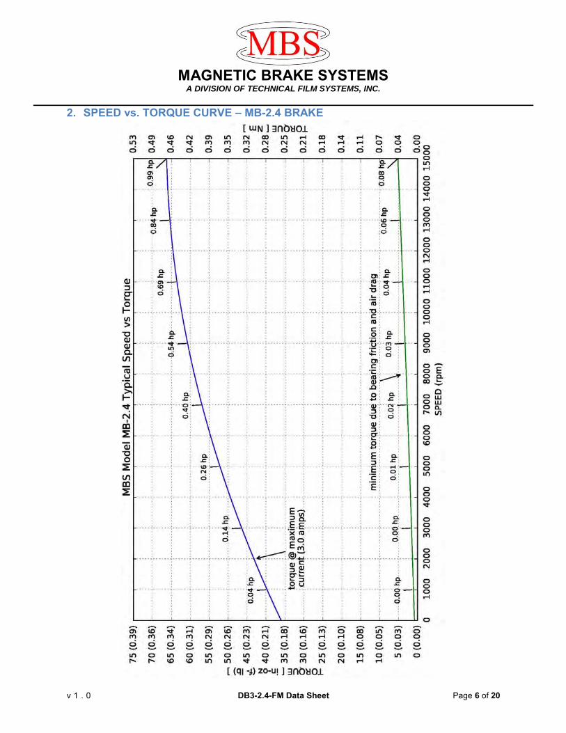
2. SPEED vs. TORQUE CURVE – MB-2.4 BRAKE

MAGNETIC BRAKE SYSTEMS
A DIVISION OF TECHNICAL FILM SYSTEMS, INC.
v 1 . 0 DB3-2.4-FM Data Sheet Page 7 of 20
3. TORQUE & SPEED OUTPUT TO MOTOR Possible speed/torque combinations based on different pulley ratios:
3.1 Pulley Ratio’s (English Units) Motor_Spd
(RPM) Motor Torque
(in-oz.) Power (HP)
Pulley Ratio (motor/brake)
Brake Torque (in-oz.)
Brake_Spd (RPM)
Time (sec)
0 144 0 4:1 36 0 cont. 2,125 240 0.5 4:1 60 8,500 cont. 3,750 268 1.0 4:1 67 15,000 cont.
Table 1: Speed, Torque & Power (English Units) 1:4 ratio
Motor_Spd (RPM)
Motor Torque (in-oz.)
Power (HP)
Pulley Ratio (motor/brake)
Brake Torque (in-oz.)
Brake_Spd (RPM)
Time (sec)
0 36 0 1:1 36 0 cont. 8,500 60 0.5 1:1 60 8,500 cont.
15,000* 67 1.0 1:1 67 15,000 cont. Table 2: Speed, Torque & Power (English Units) 1:1 ratio
Motor_Spd (RPM)
Motor Torque (in-oz.)
Power (HP)
Pulley Ratio (motor/brake)
Brake Torque (in-oz.)
Brake_Spd (RPM)
Time (sec)
0 9 0 1:4 36 0 cont. 25,000* 12.38 0.31 1:4.28 53 5,841 cont. 25,000* 13.75 0.34 1:4 55 6,250 cont.
Table 3: Speed, Torque & Power (English Units) 4:1 ratio
3.2 Pulley Ratio’s (SI Units) Motor_Spd
(RPM) Motor Torque
(Ncm) Power (watts)
Pulley Ratio (motor/brake)
Brake Torque (Ncm)
Brake_Spd (RPM)
Time (sec)
0 102 0 4:1 25.4 0 cont. 2,125 169 373 4:1 42.4 8,500 cont. 3,750 189 746 4:1 47.3 15,000 cont.
Table 4: Speed, Torque & Power (SI Units) 4:1 Pulley Ratio
Motor_Spd (RPM)
Motor Torque (Ncm)
Power (watts)
Pulley Ratio (motor/brake)
Brake Torque (Ncm)
Brake_Spd (RPM)
Time (sec)
0 25.4 0 1:1 25.4 0 cont. 8,500 42.4 373 1:1 42.4 8,500 cont.
15,000* 47.3 746 1:1 47.3 15,000 cont. Table 5: Speed, Torque & Power (SI Units) 1:1 Pulley Ratio
Motor_Spd (RPM)
Motor Torque (Ncm)
Power (watts)
Pulley Ratio (motor/brake)
Brake Torque (Ncm)
Brake_Spd (RPM)
Time (sec)
0 6.36 0 1:4 25.4 0 cont. 25,000* 8.74 224 1:4.28 35.0 5,833 cont. 25,000* 9.71 224 1:4 38.8 6,250 cont.
Table 6: Speed, Torque & Power (SI Units) 1:4 Pulley Ratio
The table is based on the performance graph for the MB-2.4 Brake, shown in Section 2. * Maximum speed is limited to the physical speed limits of the pulleys and belt.

MAGNETIC BRAKE SYSTEMS
A DIVISION OF TECHNICAL FILM SYSTEMS, INC.
v 1 . 0 DB3-2.4-FM Data Sheet Page 8 of 20
4. LOAD CELLS (Option 1: DB3B-2.4-FM, Measure Brake Torque) Load Cell Load Rating ............................................. 212 oz. (6 kg) Arm Length ............................................................. 1.5 inches (3.81 cm) Max Rated torque to Load Cell ............................... 318 in-oz. (224 Ncm) Max Brake Torque .................................................. 67 in-oz. (47.3 Ncm) Max Torque to Load Cell ........................................ 67 in-oz. (47.3 Ncm) Non-Linearity ........................................................... 0.1% of Rated Output (R.O.) Hysteresis ……………………... ............................... 0.1% of R.O. Non-Repeatability .……………... ............................. 0.05% of R.O. Zero Balance ........................................................... ±1% mV/V Compensated Temperature Range ......................... 14°F to 104°F Safe Temperature Range .……………. .................... 14°F to 140°F Temperature Effect on Output .………. .................... 0.01% of Load/°F Temperature Effect on Zero .…………..................... 0.01% of Load/°F Safe Overload ........................................................ 200% of R.O.*
5. LOAD CELLS (Option 2: DB3M-2.4-FM, Measure Motor Torque) Load Cell Load Rating ............................................ 212 oz. (6 kg) Arm Length ............................................................. 1.5 inches (3.81 cm) Max Rated torque to Load Cell ............................... 318 in-oz. (224 Ncm) Max Brake Torque .................................................. 67 in-oz. (47.3 Ncm) Max Torque to Load Cell (4:1 ratio .......................... 268 in-oz. (189 Ncm) Non-Linearity …………………... .............................. 0.1% of Rated Output (R.O.) Hysteresis ……………………... ............................... 0.1% of R.O. Non-Repeatability .……………... ............................. 0.05% of R.O. Zero Balance ………………...... ............................... ±1% mV/V Compensated Temperature Range ....... .................. 14°F to 104°F Safe Temperature Range ....................................... 14°F to 140°F Temperature Effect on Output ................................ 0.01% of Load/°F Temperature Effect on Zero .................................... 0.01% of Load/°F Safe Overload ........................................................ 200% of R.O.*
* Hard stops are in place to help prevent damage from over-load.

MAGNETIC BRAKE SYSTEMS
A DIVISION OF TECHNICAL FILM SYSTEMS, INC.
v 1 . 0 DB3-2.4-FM Data Sheet Page 9 of 20
5.1 Load Cell Accuracy Plot (in-oz.) The Torque Error plot shows the percentage error as a function of measured torque. These plots show the range that the load cell selected will accurately measure. The maximum torque to the motor is based on the pulley ratio selected for belt coupled systems. The error plot is based on published data from the load cell vendor.

MAGNETIC BRAKE SYSTEMS
A DIVISION OF TECHNICAL FILM SYSTEMS, INC.
v 1 . 0 DB3-2.4-FM Data Sheet Page 10 of 20
5.2 Load Cell Accuracy Plot (Ncm) The Torque Error plot shows the percentage error as a function of measured torque. These plots show the range that the load cell selected will accurately measure. The maximum torque to the motor is based on the pulley ratio selected for belt coupled systems. The error plot is based on published data from the load cell vendor.

MAGNETIC BRAKE SYSTEMS
A DIVISION OF TECHNICAL FILM SYSTEMS, INC.
v 1 . 0 DB3-2.4-FM Data Sheet Page 11 of 20
6. SPEED MEASUREMENT
A standard brake has five magnets (alternative quantity are optional) which trigger a hall effect sensor. The speed is averaged over one revolution of the brake. A 48-MHZ clock is used to measure the time between magnets.
Parameter Conditions Min. Typ. Max. Units Clock Error ~25°C ±30 PPM -10°C to 60°C ±50 PPM -40°C to 85°C ±100 PPM Brake Speed 5 magnets 12 180* KPM 30 magnets 2 30* KPM * Theoretical speed; actual maximum speed is limited to the speed of the brake.
7. DATA SAMPLING Sampling is the frequency of measuring and recording data; this rate is adjustable by the operator.
Parameter Conditions Min. Typ. Max. Units Sampling Rate 2.3 GHz Proc. 20 50 - ms i.e., 50 ms = 20 samples (or readings) per second.
8. LAPTOP COMPUTER Parameter Conditions Min. Typ. Max. Units Processor 2.3 GHz Memory 8 GB Display LED LCD 15.6 inches
9. POWER REQUIREMENTS
The MBS Dynamometer requires two 115 or 230 VAC power outlets: one for the laptop computer and one for the controller. The brakes in the dynamometer structure receive power from the controller.
Item Voltage Type Current Freq. # Plugs (amps) (Hz)
Controller 115/230 VAC 1.1/0.6 50/60 1 Laptop 110-240 VAC 1.2 50/60 1 Dynamometer 24 VDC 6.0 - none

MAGNETIC BRAKE SYSTEMS
A DIVISION OF TECHNICAL FILM SYSTEMS, INC.
v 1 . 0 DB3-2.4-FM Data Sheet Page 12 of 20
10. DC VOLTAGE TRANSDUCERS
10.1 Input Range…...………………………. 0 VDC to: 1, 5, 10, 50, 150, 200 up to 600 VDC Overload…………………........... 2x voltage range selected Frequency Range………........... DC only
10.2 Output Basic Accuracy…………........... 1.0% Linearity…………………........... 10% to 100% F.S. Thermal Drift……………........... 500 PPM/°C Response Time………………… 250 ms
10.3 Environmental and Physical Characteristics Operating Temperature………... 0°C to +50°C Insulation Category……………. CAT II Vibration Tested to ……………. IEC 60068-2-6, 1995 Pollution Degree………………. 2 Altitude…………………………. 2000-meter max. Insulation Voltage……...……… 2500 VDC MTBF………………….………… Greater than 100K hours Relative Humidity……………… 5% to 95%, non-condensingWeight…………………….......... 0.5 lbs.
11. AC VOLTAGE TRANSDUCERS – SINGLE PHASE 11.1 Input
Range…...……………….……… 0 VAC to: 50, 150, 250, 500, 600 VAC Overload………………….......... 2x voltage range selected Frequency Range……….......... 20 Hz to 5 kHz
11.2 Output Basic Accuracy………………… 0.5% Linearity………………...………. 10% to 100% F.S. Calibration……………...…........ True RMS sensing Thermal Drift…………………… 500 PPM/°C Response Time………….......... 250 ms
11.3 Environmental and Physical Characteristics Operating Temperature.………. 0°C to +60°C Insulation Category…….……… CAT II Vibration Tested to ….………... IEC 60068-2-6, 1995 Pollution Degree…….…………. 2 Altitude………………….………. 2000-meter max. Insulation Voltage……………… 2500 VDC MTBF…………………...………. Greater than 100K hours Relative Humidity……………… 5% to 95%, non-condensing Weight……………………......... 0.5 lbs.

MAGNETIC BRAKE SYSTEMS
A DIVISION OF TECHNICAL FILM SYSTEMS, INC.
v 1 . 0 DB3-2.4-FM Data Sheet Page 13 of 20
12. DC CURRENT TRANSDUCERS (Split Core) 12.1 Input
Range ....................................... 0 ADC to: 2, 5, 10, 20, 30, 50 up to 600 ADC Overload .................................. 4x current range selected Frequency Range .................... DC only
12.2 Output Basic Accuracy ........................1.0% Linearity ...................................10% to 100% F.S. Thermal Drift ............................500 PPM/°C Response Time………………… 250 ms
12.3 Environmental and Physical Characteristics Operating Temperature ............0°C to +50°C Insulation Category ...................CAT II Vibration Tested to ...................IEC 60068-2-6, 1995 Pollution Degree ......................2 Altitude ....................................2000-meter max. Insulation Voltage ....................2500 VDC MTBF........................................Greater than 100K hours Relative Humidity .....................5% to 95%, non-condensing Weight .....................................0.5 lbs.
13. AC CURRENT TRANSDUCERS – SINGLE PHASE (Split Core) 13.1 Input
Range ......................................0 AAC to: 5, 10, 15, 20, 25, 30, 40, 50 up to 600 AAC Overload ..................................4x current range selected Frequency Range ....................20 Hz to 5 kHz
13.2 Output Basic Accuracy ........................0.5% Linearity ...................................10% to 100% F.S. Calibration ...............................True RMS sensing Thermal Drift ............................500 PPM/°C Response Time .......................250 ms
13.3 Environmental and Physical Characteristics Operating Temperature ............0°C to +60°C Insulation Category ..................CAT II Vibration Tested to ...................IEC 60068-2-6, 1995 Pollution Degree ......................2 Altitude ....................................2000-meter max. Insulation Voltage ....................2500 VDC MTBF .......................................Greater than 100K hours Relative Humidity .....................5% to 95%, non-condensing Weight .....................................0.5 lbs.

MAGNETIC BRAKE SYSTEMS
A DIVISION OF TECHNICAL FILM SYSTEMS, INC.
v 1 . 0 DB3-2.4-FM Data Sheet Page 14 of 20
14. DYNAMOMETER LAYOUT – DB3B-2.4-FM, LOAD CELL ON BRAKE

MAGNETIC BRAKE SYSTEMS
A DIVISION OF TECHNICAL FILM SYSTEMS, INC.
v 1 . 0 DB3-2.4-FM Data Sheet Page 15 of 20
15. MOTOR MOUNTING PLATE – DB3B

MAGNETIC BRAKE SYSTEMS
A DIVISION OF TECHNICAL FILM SYSTEMS, INC.
v 1 . 0 DB3-2.4-FM Data Sheet Page 16 of 20
16. DYNAMOMETER LAYOUT – DB3M-2.4-FM, LOAD CELL ON MOTOR (OPTION 1)

MAGNETIC BRAKE SYSTEMS
A DIVISION OF TECHNICAL FILM SYSTEMS, INC.
v 1 . 0 DB3-2.4-FM Data Sheet Page 17 of 20
17. MOTOR MOUNTING PLATE – DB3M

MAGNETIC BRAKE SYSTEMS
A DIVISION OF TECHNICAL FILM SYSTEMS, INC.
v 1 . 0 DB3-2.4-FM Data Sheet Page 18 of 20
18. DYNAMOMETER LAYOUT – DB3M-2.4-BM, LOAD CELL ON MOTOR (OPTION 2)

MAGNETIC BRAKE SYSTEMS
A DIVISION OF TECHNICAL FILM SYSTEMS, INC.
v 1 . 0 DB3-2.4-FM Data Sheet Page 19 of 20
19. CONTROLLER LAYOUT

MAGNETIC BRAKE SYSTEMS
A DIVISION OF TECHNICAL FILM SYSTEMS, INC.
v 1 . 0 DB3-2.4-FM Data Sheet Page 20 of 20
20. NOMENCLATURE OF DYNAMOMETER PART NUMBER
DB5M-8.7T-FM
Motor Mounting Style: FM = Face Mount BM = Base Mount CB = Carriage Base Number of Brakes: T = Tandem System Omitting T = single brake system
Brake Size: 17.5 = MBZ-17.5 brake 8.7 = MBZ-8.7 brake 5.7 = MBZ-5.7 brake 3.7 = MBZ-3.75 brake 2.4 = MBZ-2.4 brake Load Cell Location: M = Measuring Motor Torque B = Measuring Brake Torque Centerline Distance: 3 = 3 inches from top of baseplate to centerline of motor shaft. 5 = 5 inches from top of baseplate to centerline of motor shaft System Type: B = Belt Coupled system I = Inline system D = Dynamometer The load cell(s) size(s) and type(s) of voltage & Current transducers are to be specified individually.