brake systems - autotechl.comautotechl.com/examreviews/brakesysmidtermreview.pdf · brake systems...
TRANSCRIPT
Brake Systems
Mid-Term Review
Brake Systems
Kinetic energy is energy in motion.
Disc brakes should NOT experience brake fade.
The antilock brake system prevents wheels from locking up.
Brake drum “out-of-round” is a variation in drum diameter at various locations around the drum.
Non-directional finish on the rotor friction surfaces follows the arc of rotor rotation.
Brake Systems
Brake Systems
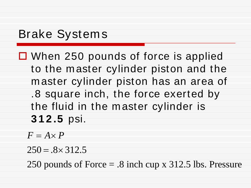
When 250 pounds of force is applied to the master cylinder piston and the master cylinder piston has an area of .8 square inch, the force exerted by the fluid in the master cylinder is 312.5 psi.
250 .8 312.5250 pounds of Force = .8 inch cup x 312.5 lbs. Pressure
F A P= ×= ×
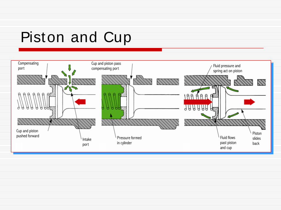
Piston and Cup
Brake Systems
When the brake pedal is depressed, the primary piston moves down the master cylinder bore and the primary cup seals the vent port.
Drum brake shoes are made from stamped steel.
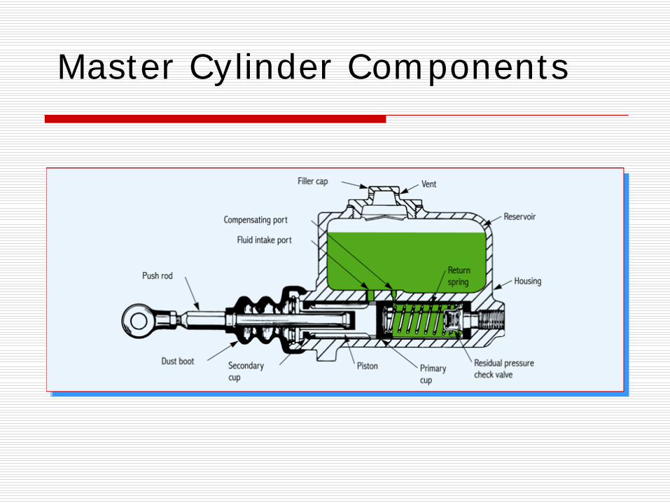
Master Cylinder Components
Brake Systems
Servo action occurs when the operation of the primary shoe applies mechanical force to the secondary shoe to assist in its application.
A floating caliper is mounted over a rotor so that it is free to slide sideways on the mounting bolts.
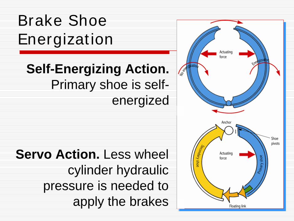
Brake Shoe Energization
Self-Energizing Action. Primary shoe is self-
energized
Servo Action. Less wheel cylinder hydraulic
pressure is needed to apply the brakes
Brake Systems
During a brake application, the proportioning valve modulates pressure to the rear brakes to prevent rear wheel lock-up.
In apply mode, the diaphragm in a vacuum booster moves the pushrod and supplies force to the master cylinder pistons to provide brake assist.
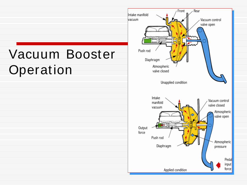
Vacuum Booster Operation
Brake Systems
In a four channel ABS (antilock braking system), both front wheels are controlled individually and both rear wheels are controlled individually.
In an ABS, the function of the hydraulic control unit (HCU) is to modulate the pressure to each of the wheels.
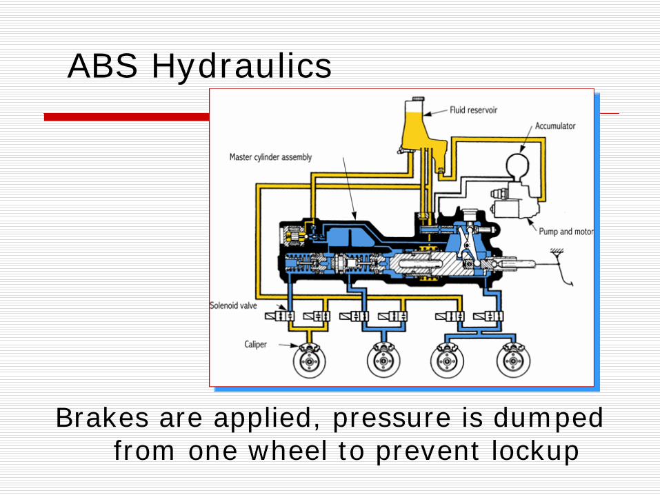
ABS Hydraulics
Brakes are applied, pressure is dumped from one wheel to prevent lockup
Brake Systems
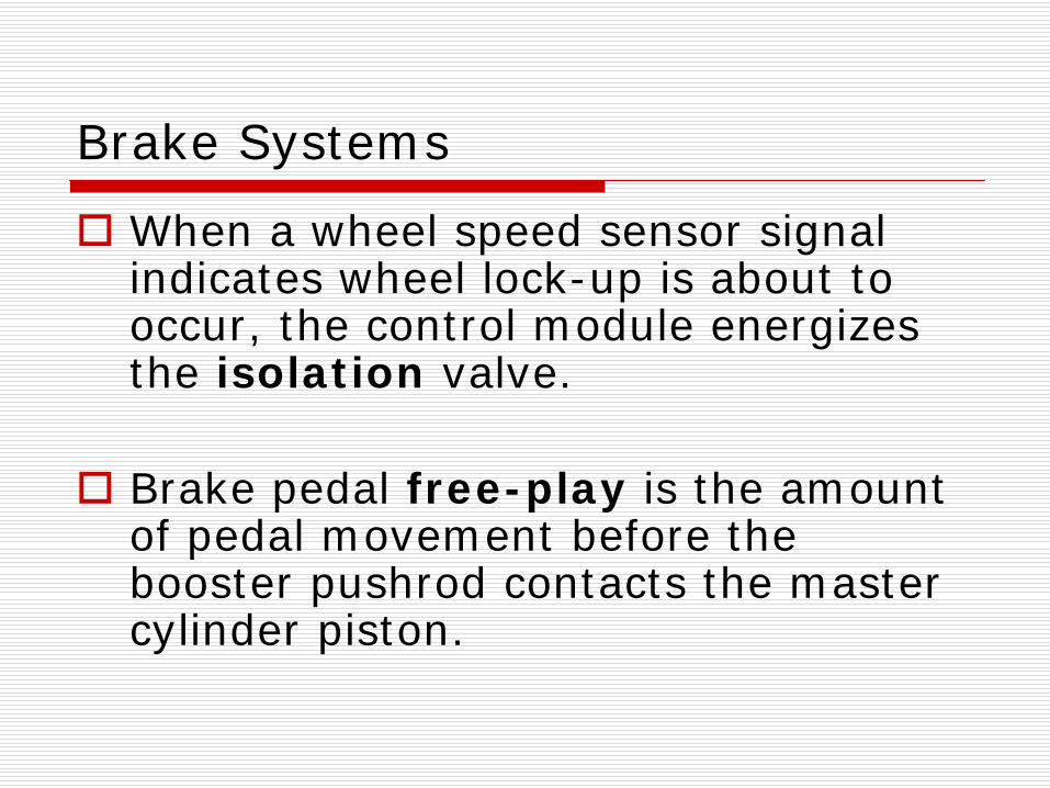
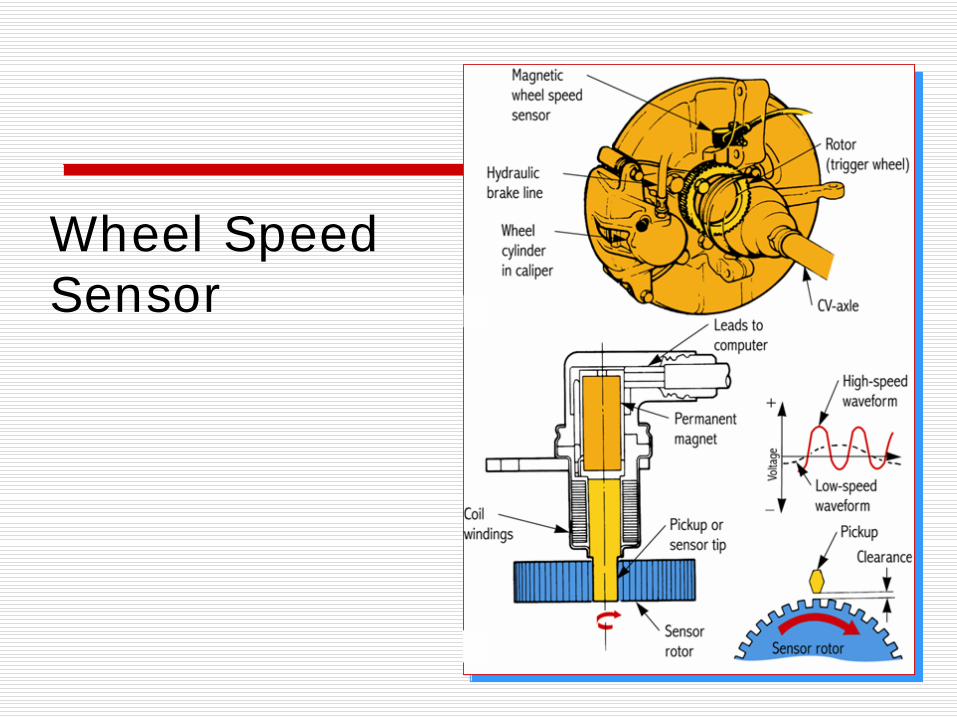
When a wheel speed sensor signal indicates wheel lock-up is about to occur, the control module energizes the isolation valve.
Brake pedal free-play is the amount of pedal movement before the booster pushrod contacts the master cylinder piston.
Wheel Speed Sensor
Brake Systems
If you observe a low spongy pedal and excessive pedal travel with the red brake warning light on, you can identify air in the hydraulic systemas the most likely cause.
If you observe premature rear wheel lockup, you can identify a defective proportioning valve as the most likely cause.
Brake Systems
When you perform reverse bleeding, brake fluid is forced into the brake bleeders and flows through the brake system as if it were brake fluid traveling back to the master cylinder when the brakes were released.
Brake Systems
If a brake drum taper or out-of-round exceeds 0.152 millimeters, the drum must be machined or replaced.
The rotor discard thickness is stamped on the rotor.
1 inch 25.400.152 .006
mmmm=
=
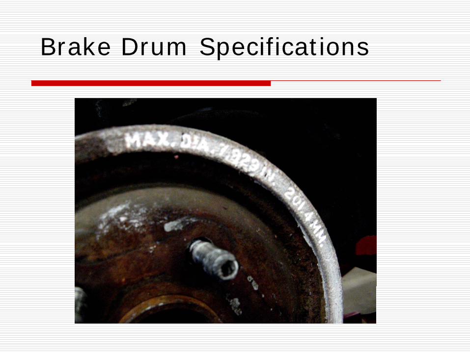
Brake Drum Specifications
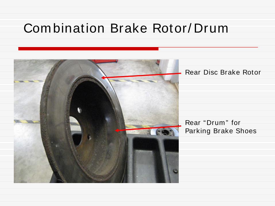
Combination Brake Rotor/Drum
Rear Disc Brake Rotor
Rear “Drum” for Parking Brake Shoes
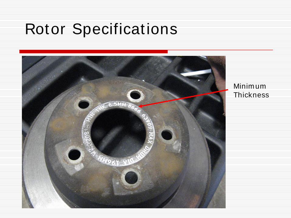
Rotor Specifications
Minimum Thickness
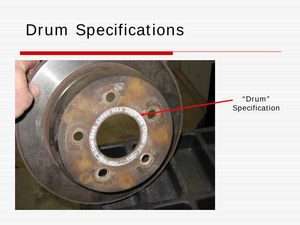
Drum Specifications
“Drum” Specification
Brake Systems
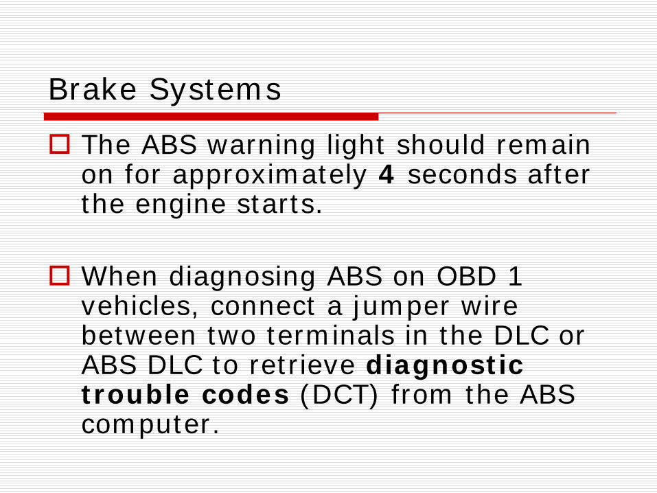
The ABS warning light should remain on for approximately 4 seconds after the engine starts.
When diagnosing ABS on OBD 1 vehicles, connect a jumper wire between two terminals in the DLC or ABS DLC to retrieve diagnostic trouble codes (DCT) from the ABS computer.
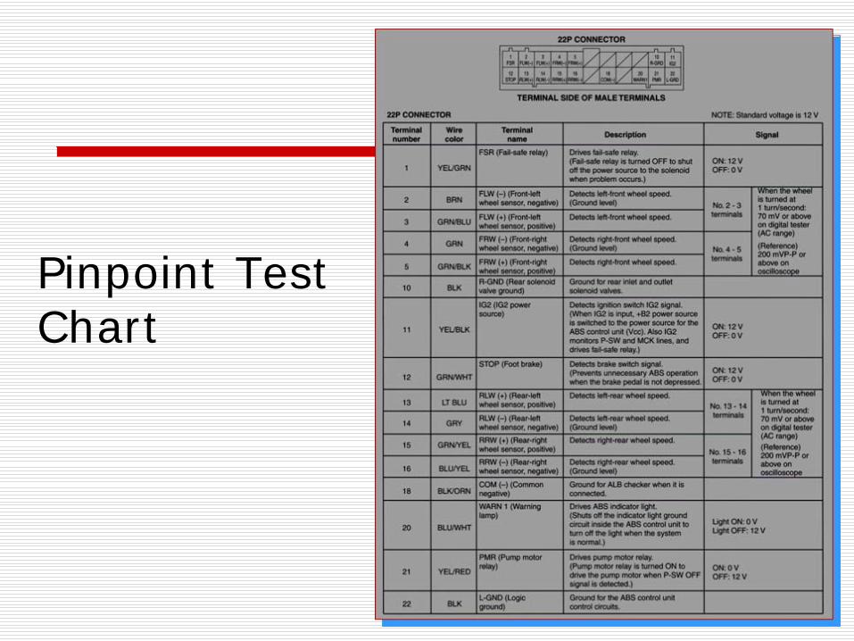
Pinpoint Test Chart
Brake Systems
The brake fluid level should be about a 1/4” from the top of the master cylinder reservoir.
An ohmmeter displays a lower than specified resistance for a shorted winding in a wheel-speed sensor.