maestro ship structural design - ndar. · pdf file · 2008-12-11maestro ship...
TRANSCRIPT

MAESTRO Ship Structural Design
DRS C3 Advanced Technology Center149 Log Canoe CircleStevensville, MD 21666

MAESTRO Ship Structural Design
What is MAESTRO?
METHOD for
ANALYSIS
EVALUATION and
STRUCTURALOPTIMIZATION
MAESTRO Ship Structural Design
What is MAESTRO?
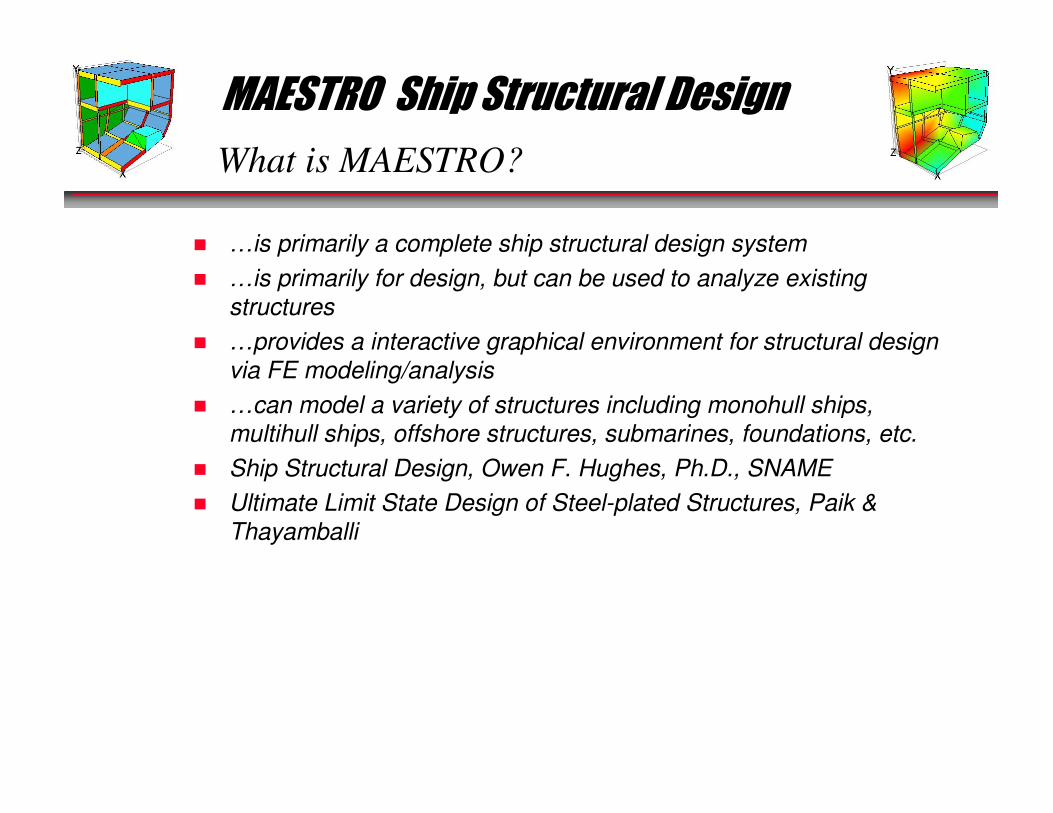
� …is primarily a complete ship structural design system
� …is primarily for design, but can be used to analyze existing
structures
� …provides a interactive graphical environment for structural design
via FE modeling/analysis
� …can model a variety of structures including monohull ships,
multihull ships, offshore structures, submarines, foundations, etc.
� Ship Structural Design, Owen F. Hughes, Ph.D., SNAME
� Ultimate Limit State Design of Steel-plated Structures, Paik &
Thayamballi

MAESTRO Ship Structural Design
MAESTRO Main Capabilities
� Rapid Structural Modeling
� Ship-based Loading
� Finite Element Analysis
� Structural Evaluation
� Optimization (Scalable Solver)
� Fine mesh Analysis
� Natural Frequency
MAESTRO is a complete ship structural design system:

MAESTRO Ship Structural Design
Main Capabilities-Structural Modeling
=
+
+
+
MAESTRO Ship Structural Design
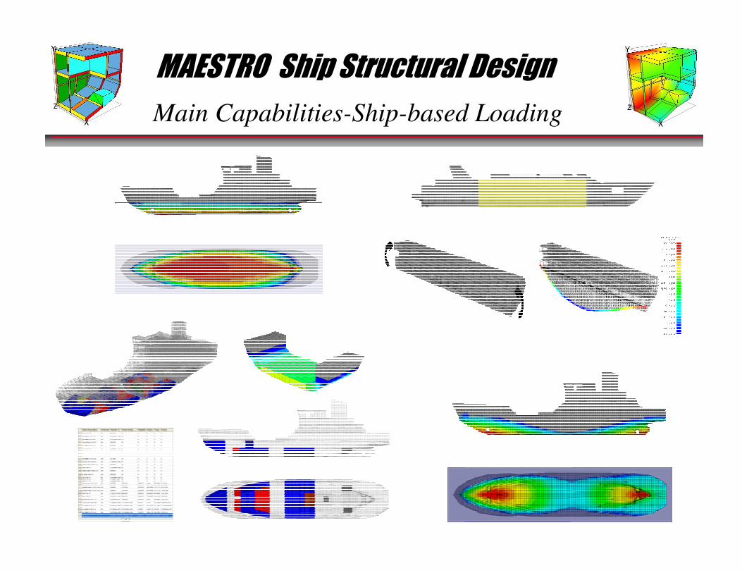
Main Capabilities-Ship-based Loading
MAESTRO Ship Structural Design
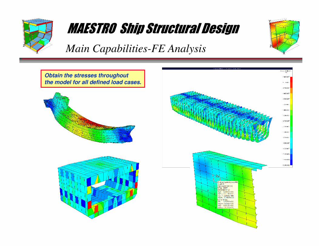
Main Capabilities-FE Analysis
Obtain the stresses throughoutthe model for all defined load cases.
MAESTRO Ship Structural Design
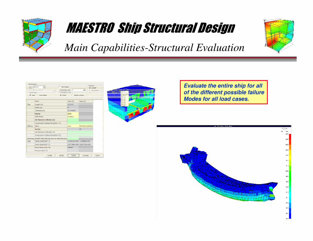
Main Capabilities-Structural Evaluation
Evaluate the entire ship for allof the different possible failureModes for all load cases.
MAESTRO Ship Structural Design
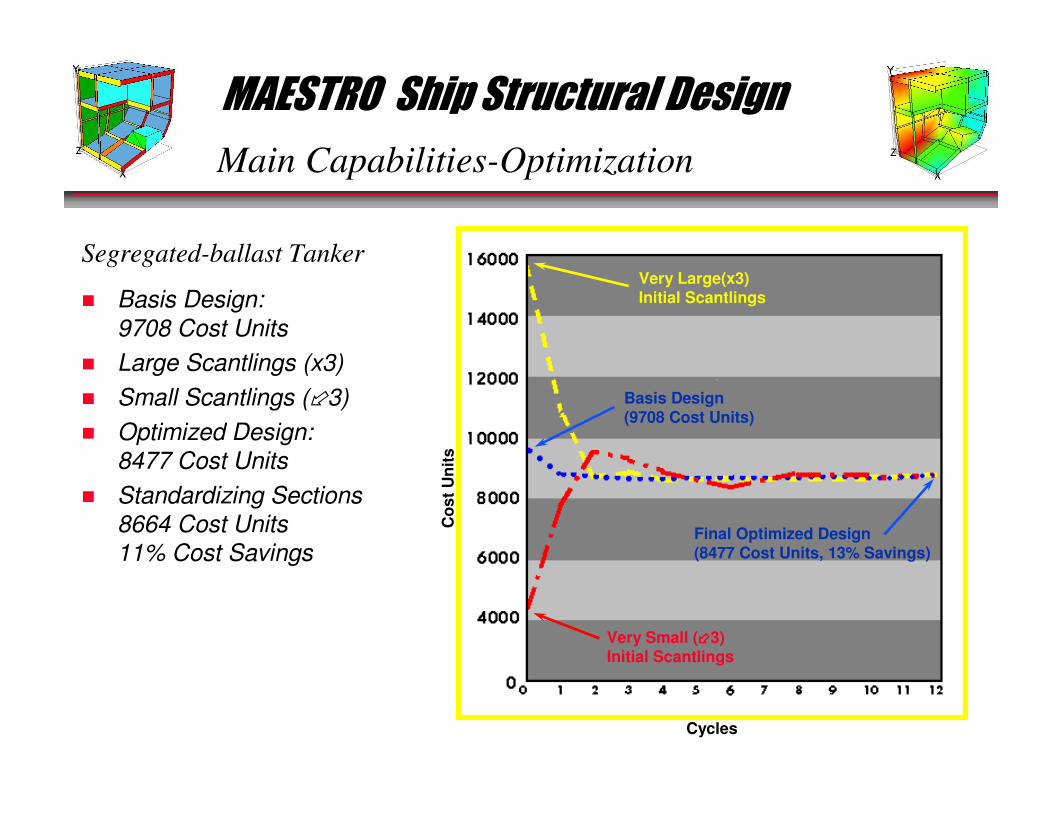
Main Capabilities-Optimization
Very Large(x3)Initial Scantlings
Very Small (����3)Initial Scantlings
Final Optimized Design(8477 Cost Units, 13% Savings)
Cycles
Co
st
Un
its
Basis Design(9708 Cost Units)
� Basis Design:
9708 Cost Units
� Large Scantlings (x3)
� Small Scantlings (�3)
� Optimized Design:
8477 Cost Units
� Standardizing Sections
8664 Cost Units
11% Cost Savings
Segregated-ballast Tanker
MAESTRO Ship Structural Design
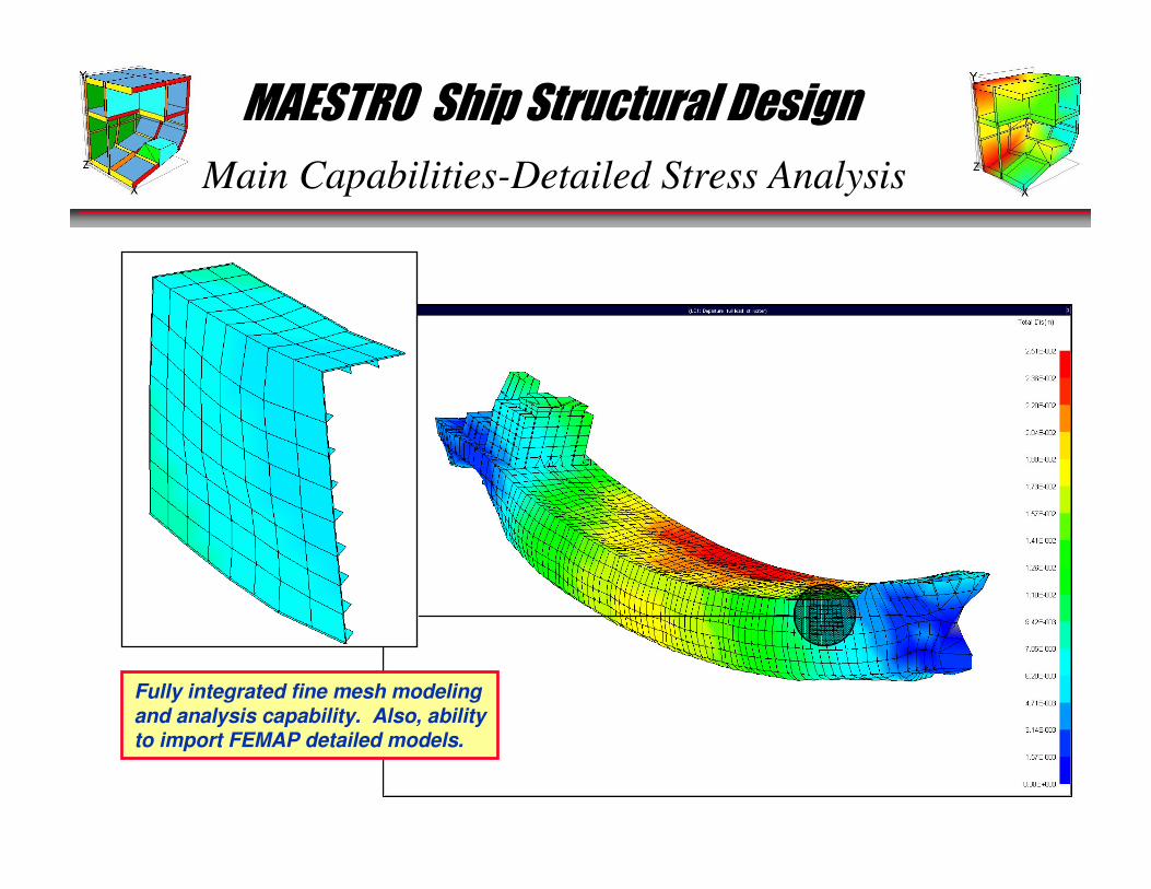
Main Capabilities-Detailed Stress Analysis
Fully integrated fine mesh modelingand analysis capability. Also, abilityto import FEMAP detailed models.
MAESTRO Ship Structural Design
Main Capabilities-Vibration Analysis
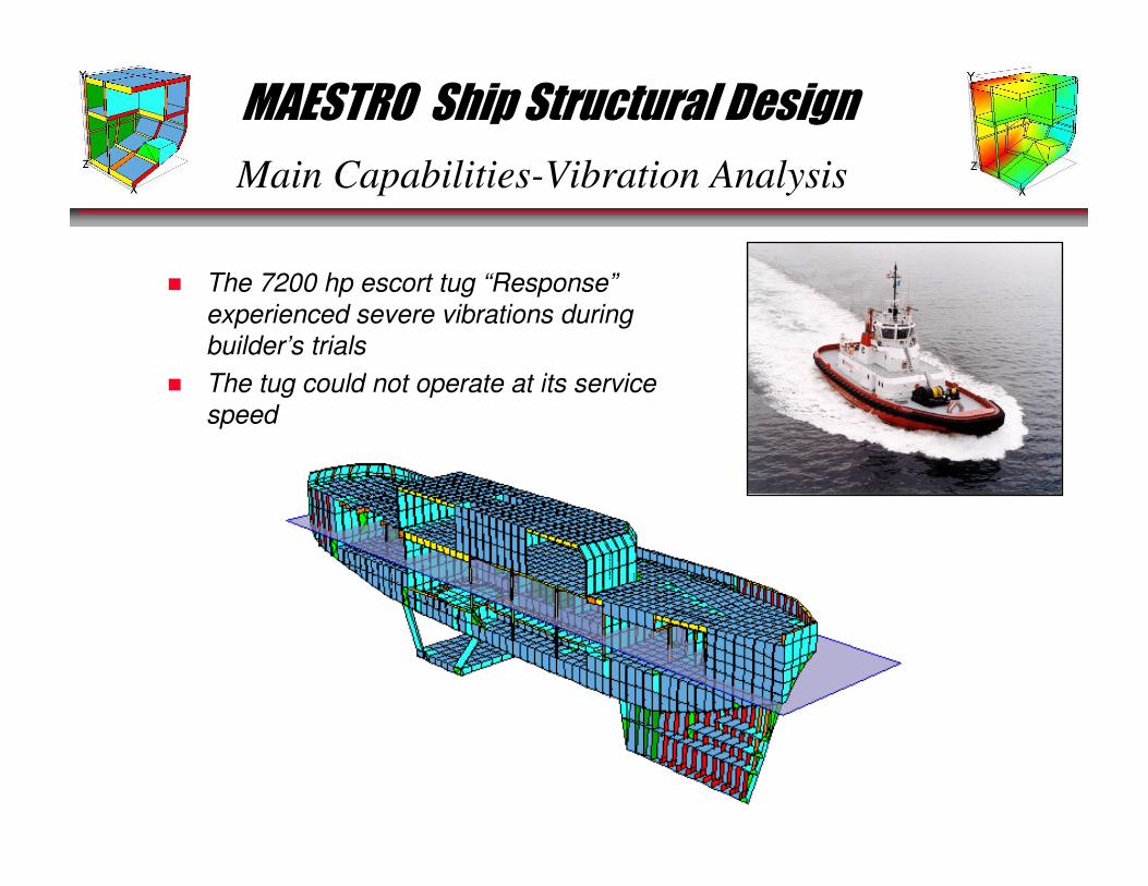
� The 7200 hp escort tug “Response”
experienced severe vibrations during
builder’s trials
� The tug could not operate at its service
speed
MAESTRO Ship Structural Design
Main Capabilities-Vibration Analysis (cont’d)
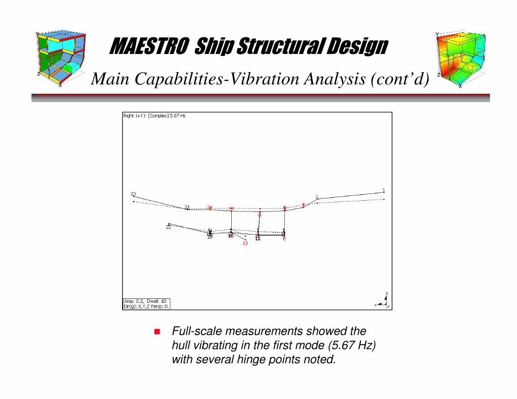
� Full-scale measurements showed the
hull vibrating in the first mode (5.67 Hz)
with several hinge points noted.
MAESTRO Ship Structural Design
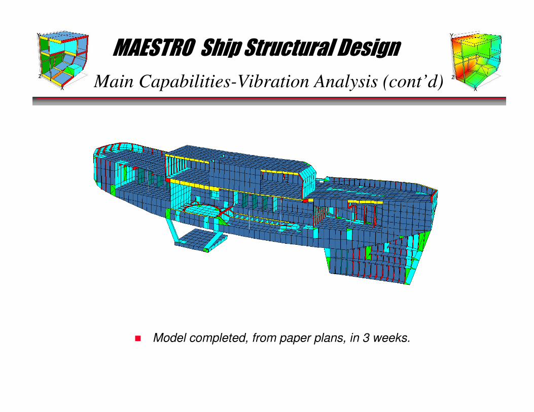
Main Capabilities-Vibration Analysis (cont’d)
� Model completed, from paper plans, in 3 weeks.
MAESTRO Ship Structural Design
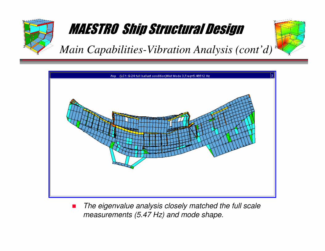
Main Capabilities-Vibration Analysis (cont’d)
� The eigenvalue analysis closely matched the full scale
measurements (5.47 Hz) and mode shape.
MAESTRO Ship Structural Design
Main Capabilities-Vibration Analysis (cont’d)
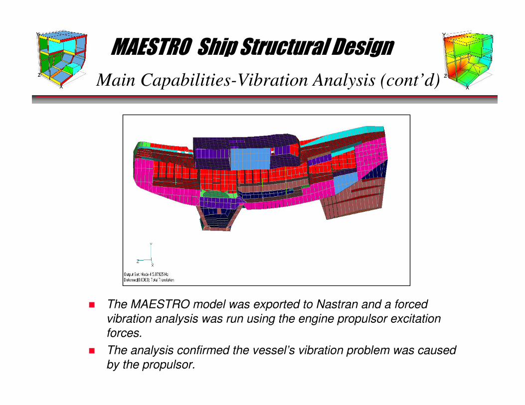
� The MAESTRO model was exported to Nastran and a forced
vibration analysis was run using the engine propulsor excitation
forces.
� The analysis confirmed the vessel’s vibration problem was caused
by the propulsor.

MAESTRO Ship Structural Design
Main Capabilities-Vibration Analysis (cont’d)
� MAESTRO was used to re-design the tug until an acceptable
change in the tug’s first mode frequency was reached.
� The re-design effort was conducted on-site in hours, not days or
weeks.
Bulwark was changedto a box beam girder, ashear strake doubleplate was added, and akeel doubler was added.

MAESTRO Ship Structural Design
MAESTRO Main Capabilities
� Rapid Structural Modeling
� Ship-based Loading
� Finite Element Analysis
� Structural Evaluation
� Optimization
� Detailed Stress Analysis
� Natural Frequency
MAESTRO is a complete ship structural design system:
MAESTRO Ship Structural Design
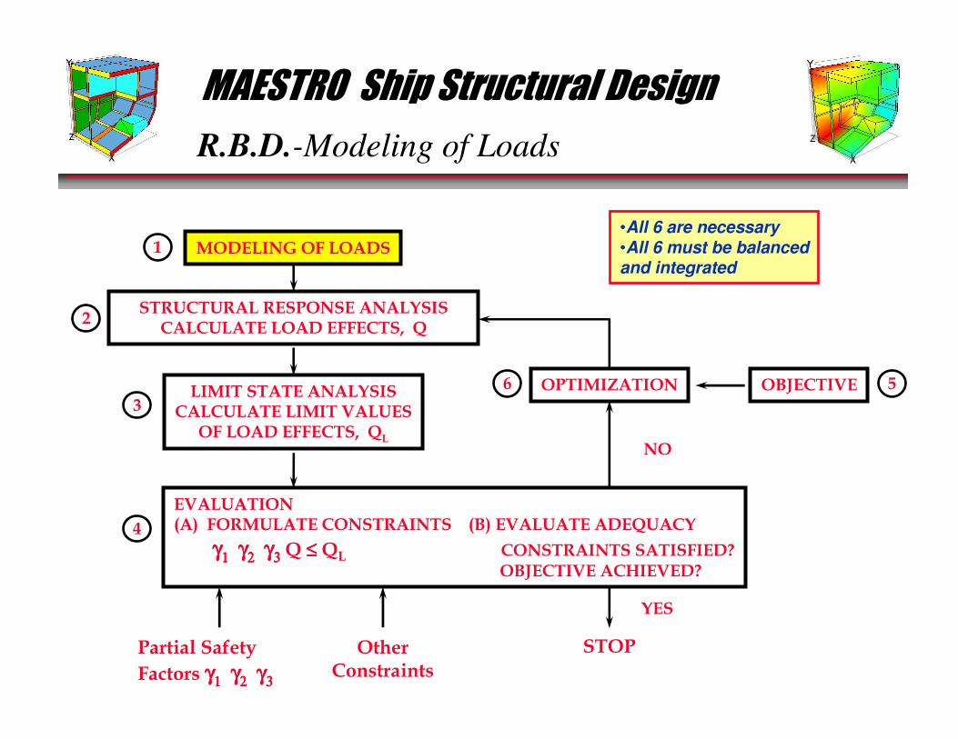
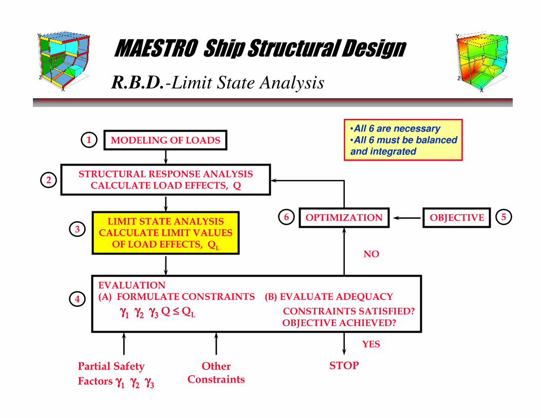
R.B.D.-Modeling of Loads
MODELING OF LOADS
STRUCTURAL RESPONSE ANALYSISCALCULATE LOAD EFFECTS, Q
LIMIT STATE ANALYSISCALCULATE LIMIT VALUES
OF LOAD EFFECTS, QL
OPTIMIZATION OBJECTIVE
1
OtherConstraints
YES
STOP
NO
Partial Safety
Factors γγγγ1111 γγγγ2222 γγγγ3333
EVALUATION(A) FORMULATE CONSTRAINTS (B) EVALUATE ADEQUACY
γγγγ1111 γγγγ2222 γγγγ3333 Q ≤≤≤≤ QL CONSTRAINTS SATISFIED?OBJECTIVE ACHIEVED?
2
3
4
56
•All 6 are necessary•All 6 must be balancedand integrated

MAESTRO Ship Structural Design
R.B.D.-Modeling of Loads
� Lightship mass distribution:
� Hydrostatic loads:• Stillwater
• Waves
� Tank loads
� Cargo masses• Forces
• Moments
� Accelerations (6 d.o.f.)
� Pressure loads
� External bending moments and
shear
force at ends of partial models
� Boundary conditions
Loads are ship-based and easy to apply:
MAESTRO Ship Structural Design
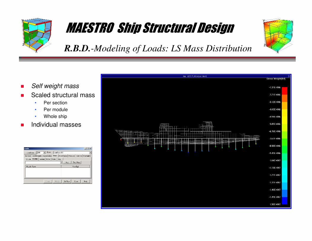
R.B.D.-Modeling of Loads: LS Mass Distribution
� Self weight mass
� Scaled structural mass• Per section
• Per module
• Whole ship
� Individual masses
MAESTRO Ship Structural Design
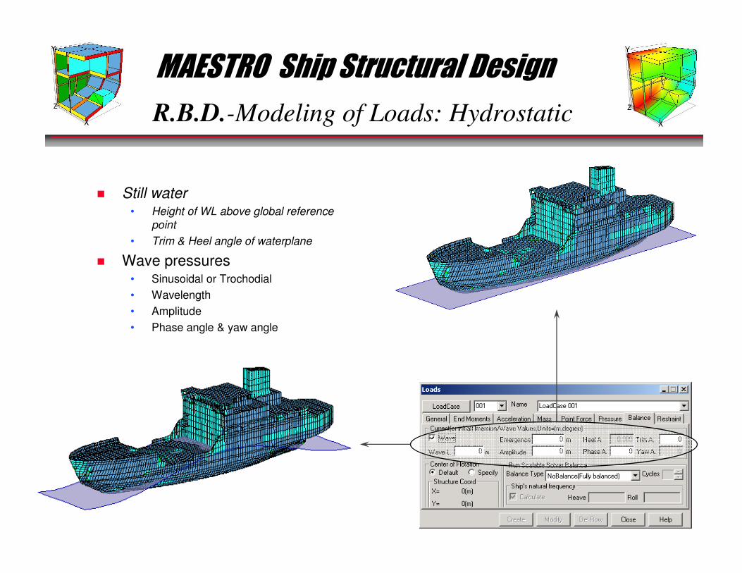
R.B.D.-Modeling of Loads: Hydrostatic
� Still water• Height of WL above global reference
point
• Trim & Heel angle of waterplane
� Wave pressures• Sinusoidal or Trochodial
• Wavelength
• Amplitude
• Phase angle & yaw angle
MAESTRO Ship Structural Design
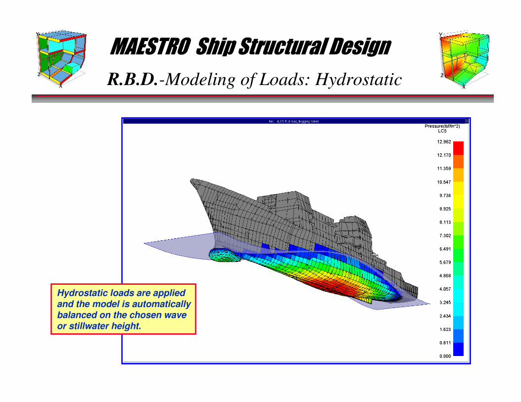
R.B.D.-Modeling of Loads: Hydrostatic
Hydrostatic loads are appliedand the model is automaticallybalanced on the chosen waveor stillwater height.
MAESTRO Ship Structural Design
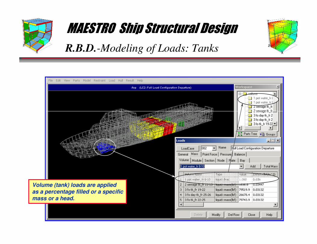
R.B.D.-Modeling of Loads: Tanks
Volume (tank) loads are appliedas a percentage filled or a specificmass or a head.
MAESTRO Ship Structural Design
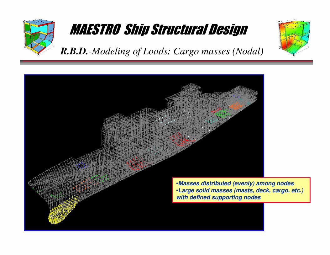
R.B.D.-Modeling of Loads: Cargo masses (Nodal)
•Masses distributed (evenly) among nodes•Large solid masses (masts, deck, cargo, etc.) with defined supporting nodes
MAESTRO Ship Structural Design
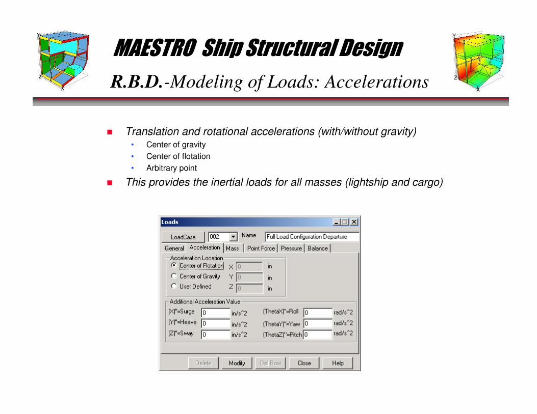
R.B.D.-Modeling of Loads: Accelerations
� Translation and rotational accelerations (with/without gravity)• Center of gravity
• Center of flotation
• Arbitrary point
� This provides the inertial loads for all masses (lightship and cargo)
MAESTRO Ship Structural Design
R.B.D.-Modeling of Loads: Pressure
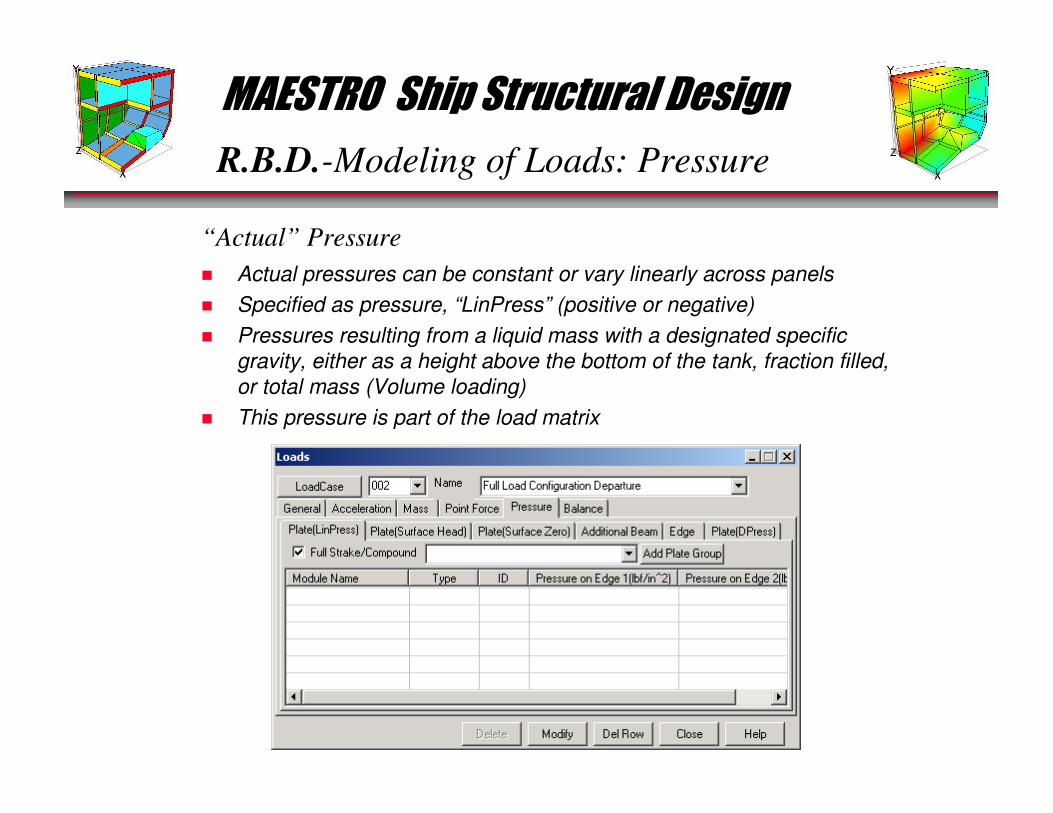
� Actual pressures can be constant or vary linearly across panels
� Specified as pressure, “LinPress” (positive or negative)
� Pressures resulting from a liquid mass with a designated specific
gravity, either as a height above the bottom of the tank, fraction filled,
or total mass (Volume loading)
� This pressure is part of the load matrix
“Actual” Pressure

MAESTRO Ship Structural Design
R.B.D.-Modeling of Loads: Pressure
� Added to the panel after the FE solution/considered during evaluation
� Design pressures (additive/generic)• Additive – added during evaluation on top of any other pressure (e.g. ice loads)
• Generic – are made the “lower bound” pressure on the specified panels during
evaluation
“Design” Pressure
MAESTRO Ship Structural Design
R.B.D.-Modeling of Loads: External BM/Shear
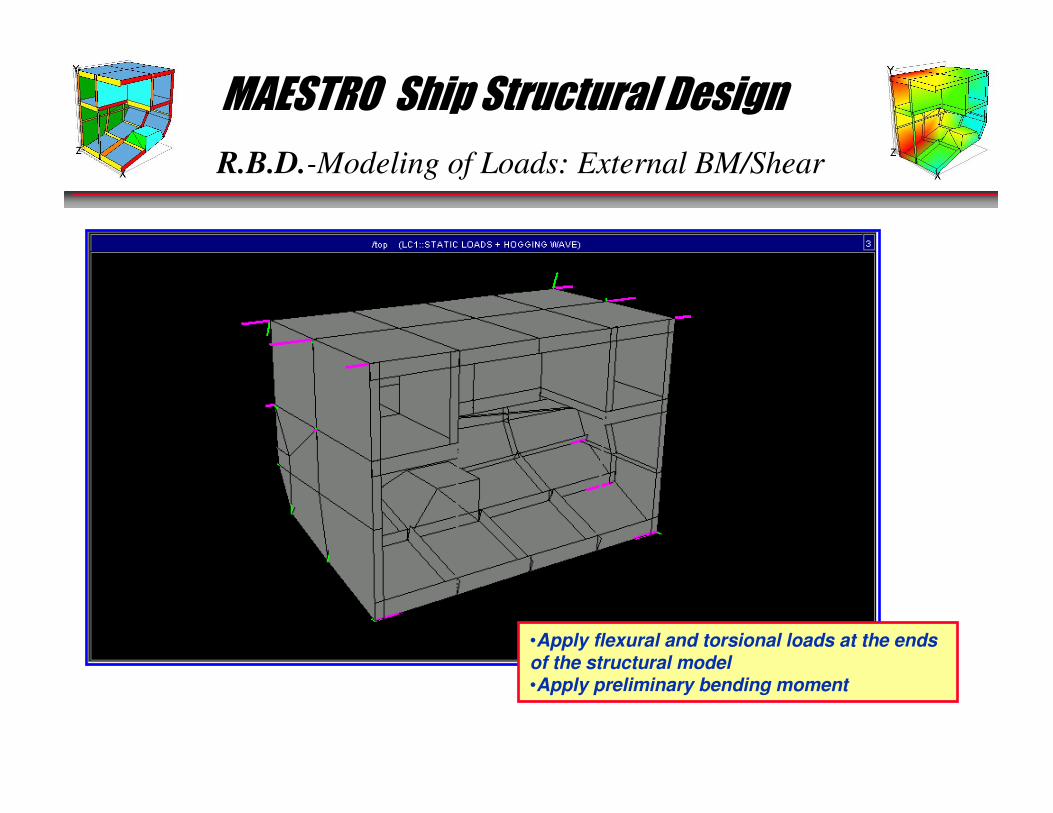
•Apply flexural and torsional loads at the ends of the structural model•Apply preliminary bending moment

MAESTRO Ship Structural Design
R.B.D.-Modeling of Loads: External BM
The station values (user defined) are displayed and can be easilly cut and pasted to MS-Word/Excel.
MAESTRO Ship Structural Design
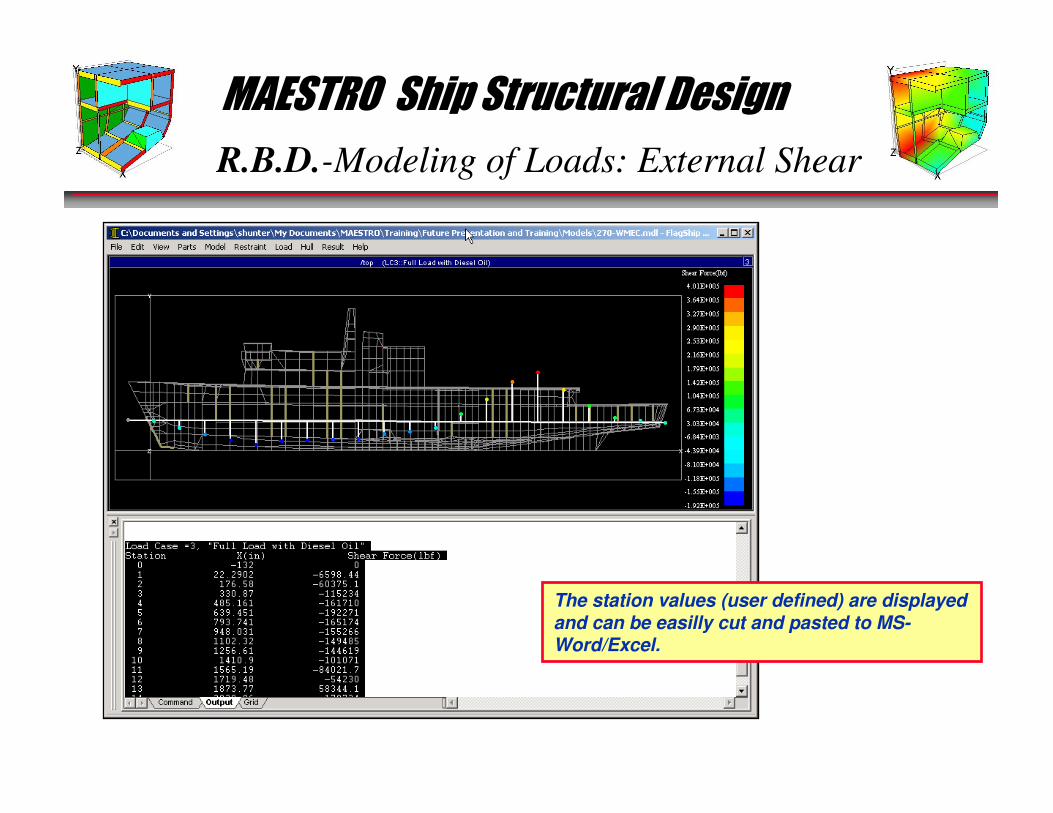
R.B.D.-Modeling of Loads: External Shear
The station values (user defined) are displayed and can be easilly cut and pasted to MS-Word/Excel.
MAESTRO Ship Structural Design
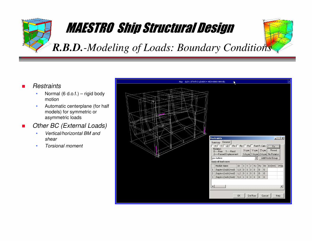
R.B.D.-Modeling of Loads: Boundary Conditions
� Restraints• Normal (6 d.o.f.) – rigid body
motion
• Automatic centerplane (for half
models) for symmetric or
asymmetric loads
� Other BC (External Loads)• Vertical/horizontal BM and
shear
• Torsional moment
MAESTRO Ship Structural Design
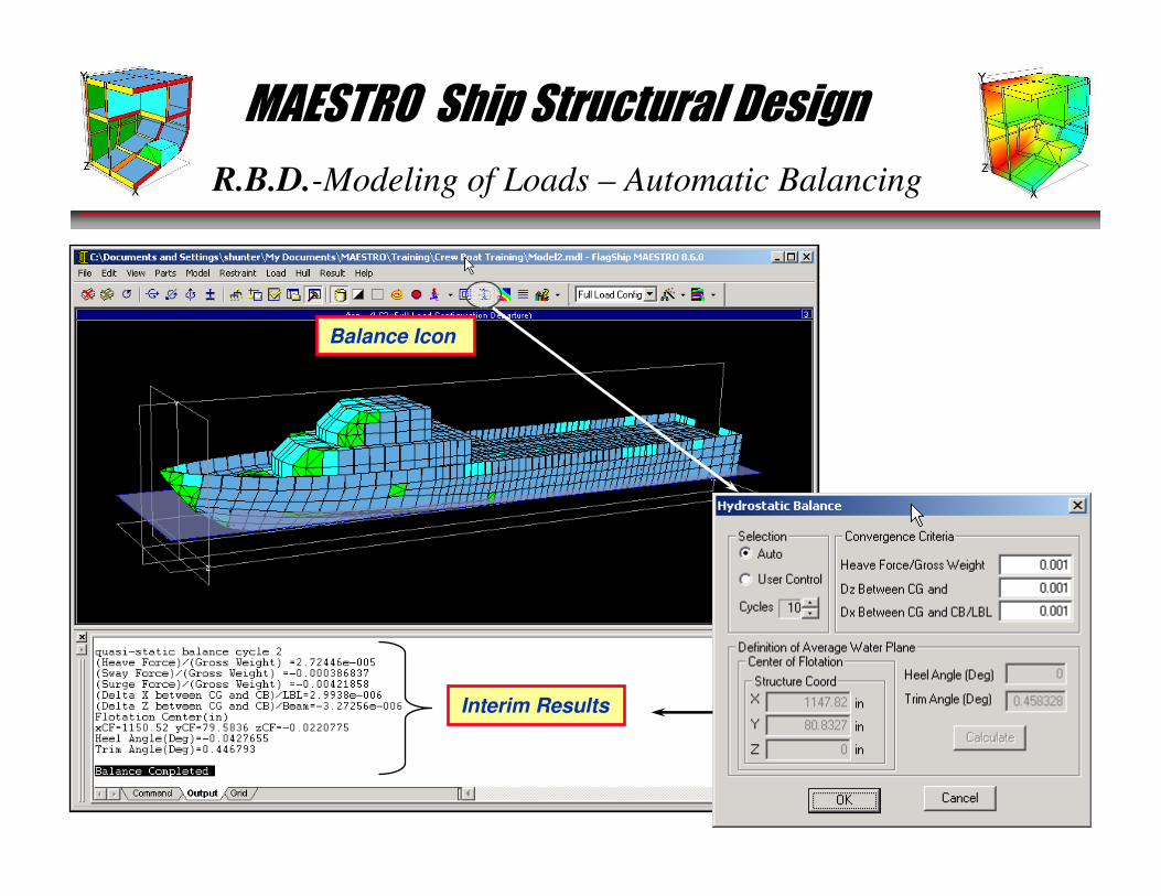
R.B.D.-Modeling of Loads – Automatic Balancing
Interim Results
Balance Icon

MAESTRO Ship Structural Design
R.B.D.-Structural Response Analysis
MODELING OF LOADS
STRUCTURAL RESPONSE ANALYSISCALCULATE LOAD EFFECTS, Q
LIMIT STATE ANALYSISCALCULATE LIMIT VALUES
OF LOAD EFFECTS, QL
OPTIMIZATION OBJECTIVE
1
OtherConstraints
YES
STOP
NO
Partial Safety
Factors γγγγ1111 γγγγ2222 γγγγ3333
EVALUATION(A) FORMULATE CONSTRAINTS (B) EVALUATE ADEQUACY
γγγγ1111 γγγγ2222 γγγγ3333 Q ≤≤≤≤ QL CONSTRAINTS SATISFIED?OBJECTIVE ACHIEVED?
2
3
4
56
•All 6 are necessary•All 6 must be balancedand integrated
MAESTRO Ship Structural Design
R.B.D.-Structural Response Analysis
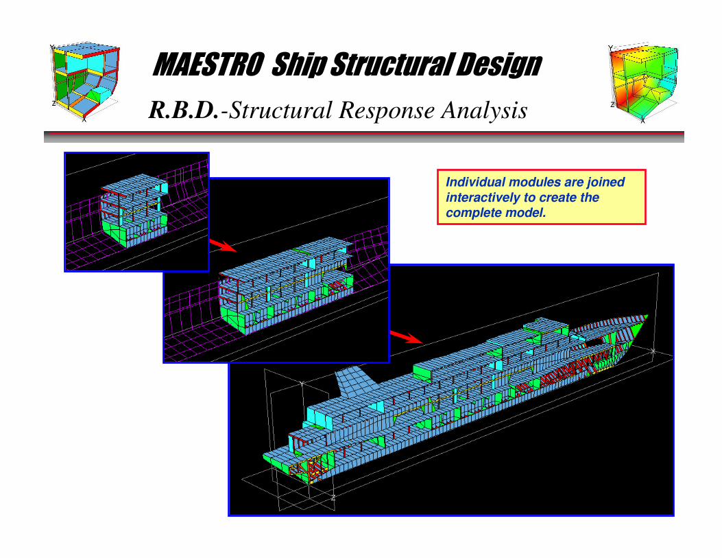
Individual modules are joined interactively to create the complete model.
MAESTRO Ship Structural Design
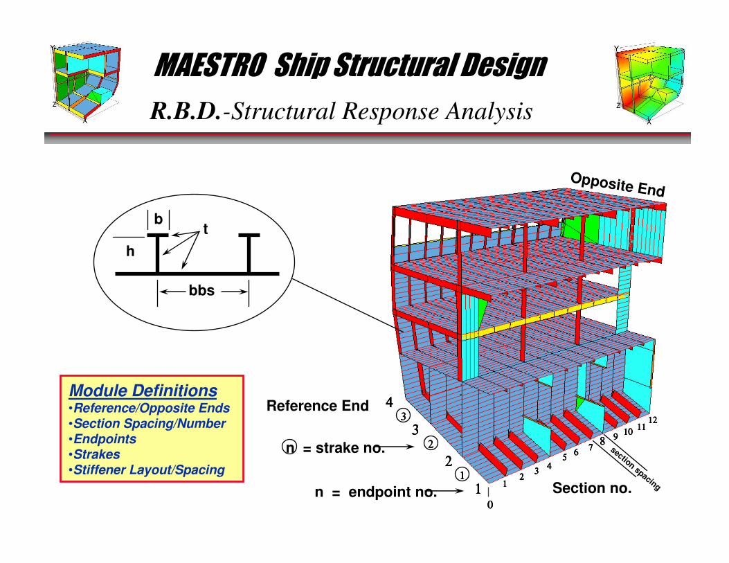
R.B.D.-Structural Response Analysis
Module Definitions•Reference/Opposite Ends•Section Spacing/Number•Endpoints•Strakes•Stiffener Layout/Spacing
h
bt
bbs
11112222
33334444
55556666
7777
999910101010
11111111
0000
1111
2222
3333
4444
1111
2222
3333
Section no.n = endpoint no.
n = strake no.
Opposite End
Reference End
8888section spacing
12121212
MAESTRO Ship Structural Design
R.B.D.-Structural Response Analysis
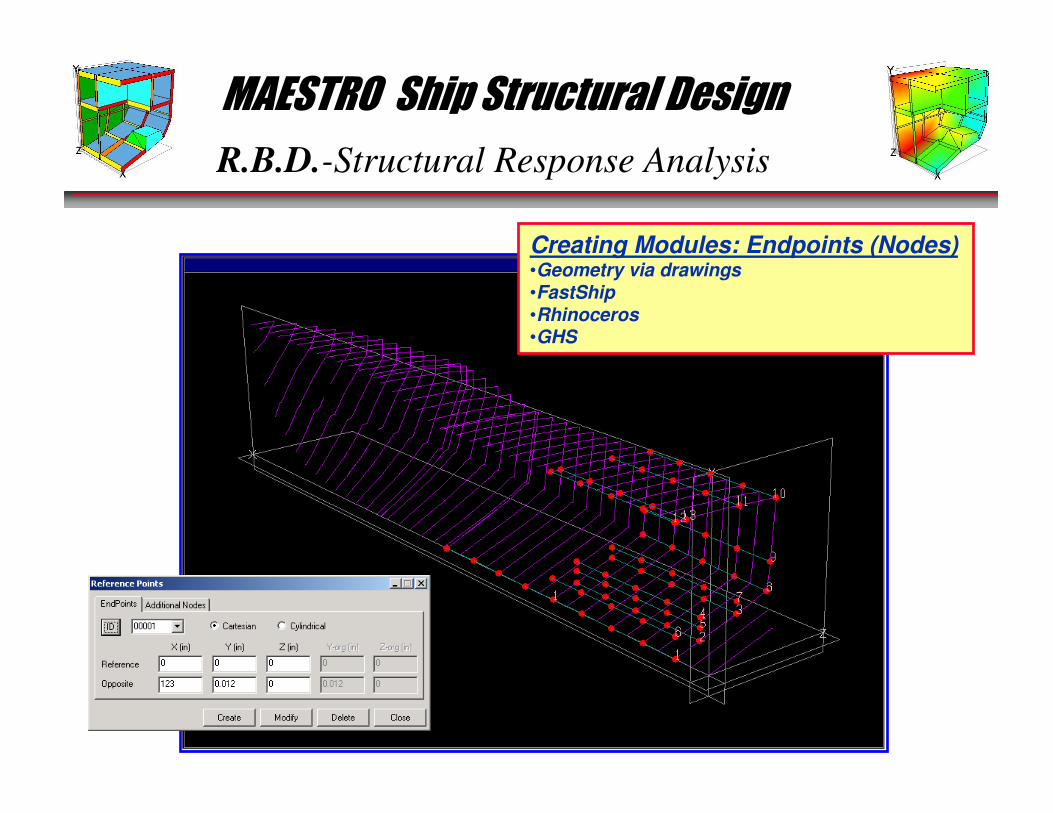
Creating Modules: Endpoints (Nodes)•Geometry via drawings•FastShip•Rhinoceros•GHS
MAESTRO Ship Structural Design
R.B.D.-Structural Response Analysis
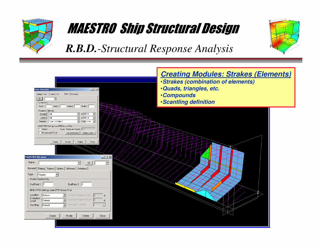
Creating Modules: Strakes (Elements)•Strakes (combination of elements)•Quads, triangles, etc.•Compounds•Scantling definition
MAESTRO Ship Structural Design
R.B.D.-Structural Response Analysis
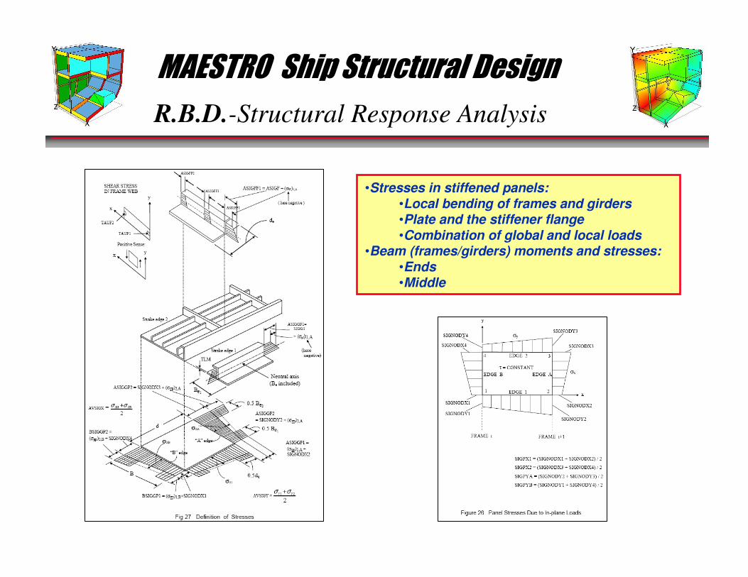
•Stresses in stiffened panels:•Local bending of frames and girders•Plate and the stiffener flange•Combination of global and local loads
•Beam (frames/girders) moments and stresses:•Ends•Middle
MAESTRO Ship Structural Design
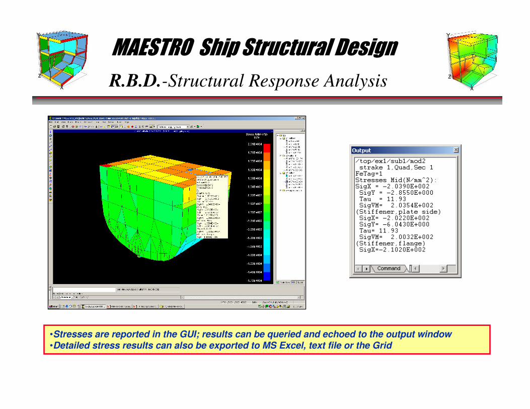
R.B.D.-Structural Response Analysis
•Stresses are reported in the GUI; results can be queried and echoed to the output window•Detailed stress results can also be exported to MS Excel, text file or the Grid
MAESTRO Ship Structural Design
R.B.D.-Structural Response Analysis
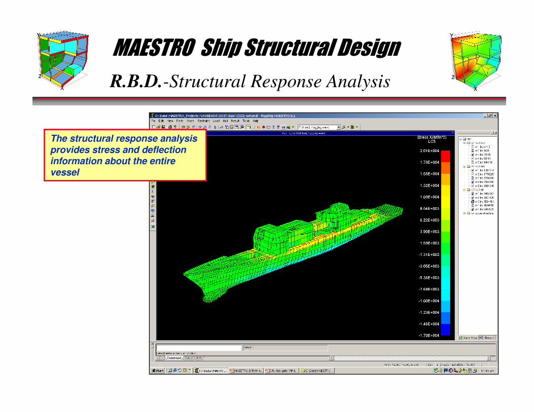
The structural response analysis provides stress and deflection information about the entire vessel
MAESTRO Ship Structural Design
R.B.D.-Structural Response Analysis
� QUAD4 and hybrid beam elements have been verified against theory
and other FE codes (MSC-Nastran and ABAQUS)
� QUAD4 Verification• Tested against standard test problems published by MacNeal and Harder (“A
Proposed Standard Set of Problems to Test Finite Element Accuracy”, Finite Elements
in Analysis and Design 1, pp. 3-20, 1985)
– Patch Test
– Cantilever Beam Test
– Curved Beam Test
– Twisted Beam Test
– Rectangular Plate Test
– Scordelis-Lo Roof Test
• The results show either similar or better level of accuracy as the results from Nastran or ABAQUS
� Beam element• MAESTRO obtains an exact solution for maximum displacement with two elements
(the minimum possible)
• MAESTRO obtains and exact solution for maximum bending moment with a single
element
� Complete results are found in the MAESTRO Verification Manual
MAESTRO Verification Procedure
MAESTRO Ship Structural Design
R.B.D.-Limit State Analysis
MODELING OF LOADS
STRUCTURAL RESPONSE ANALYSISCALCULATE LOAD EFFECTS, Q
LIMIT STATE ANALYSISCALCULATE LIMIT VALUES
OF LOAD EFFECTS, QL
OPTIMIZATION OBJECTIVE
1
OtherConstraints
YES
STOP
NO
Partial Safety
Factors γγγγ1111 γγγγ2222 γγγγ3333
EVALUATION(A) FORMULATE CONSTRAINTS (B) EVALUATE ADEQUACY
γγγγ1111 γγγγ2222 γγγγ3333 Q ≤≤≤≤ QL CONSTRAINTS SATISFIED?OBJECTIVE ACHIEVED?
2
3
4
56
•All 6 are necessary•All 6 must be balancedand integrated
MAESTRO Ship Structural Design
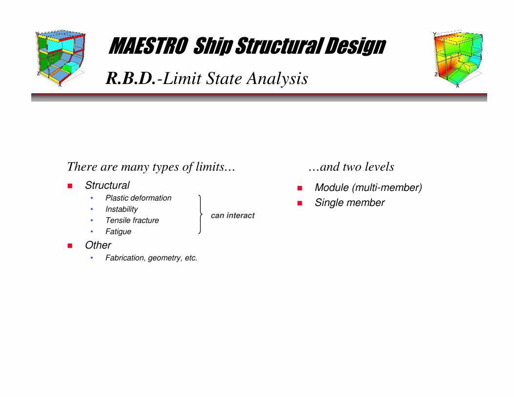
R.B.D.-Limit State Analysis
� Structural• Plastic deformation
• Instability
• Tensile fracture
• Fatigue
� Other• Fabrication, geometry, etc.
There are many types of limits… …and two levels
� Module (multi-member)
� Single membercan interact
MAESTRO Ship Structural Design
R.B.D.-Limit State Analysis-Module Level
� Progressive collapse
� Fatigue
� Deflection limits
� Stress limits
Overall Structure
� General buckling
� Bay buckling
� Local buckling
Cylinder Collapse
UNSTIFFENED
RING STIFFENED
STRINGER STIFFENED
RING AND STRINGERSTIFFENED
LOCAL STIFFENER BUCKLING
LOCAL SHELL BUCKLING
LOCAL SHELL BUCKLING
GENERAL INSTABILITY
LOCAL STIFFENER BUCKLING
LOCAL SHELL BUCKLING
LOCAL SHELL BUCKLING
BAY INSTABILITY
BAY INSTABILITY
GENERAL INSTABILITY
LOCAL STIFFENER BUCKLING
API Bulletin 2U
MAESTRO Ship Structural Design
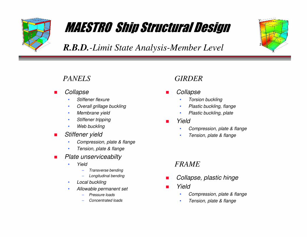
R.B.D.-Limit State Analysis-Member Level
� Collapse• Stiffener flexure
• Overall grillage buckling
• Membrane yield
• Stiffener tripping
• Web buckling
� Stiffener yield• Compression, plate & flange
• Tension, plate & flange
� Plate unserviceabilty• Yield
– Transverse bending
– Longitudinal bending
• Local buckling
• Allowable permanent set
– Pressure loads
– Concentrated loads
PANELS
� Collapse• Torsion buckling
• Plastic buckling, flange
• Plastic buckling, plate
� Yield• Compression, plate & flange
• Tension, plate & flange
GIRDER
� Collapse, plastic hinge
� Yield• Compression, plate & flange
• Tension, plate & flange
FRAME
MAESTRO Ship Structural Design
R.B.D.- Limit State Analysis: Theory
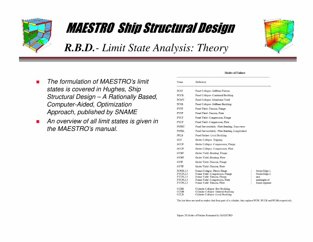
� The formulation of MAESTRO’s limit
states is covered in Hughes, Ship
Structural Design – A Rationally Based,
Computer-Aided, Optimization
Approach, published by SNAME
� An overview of all limit states is given in
the MAESTRO’s manual.
MAESTRO Ship Structural Design
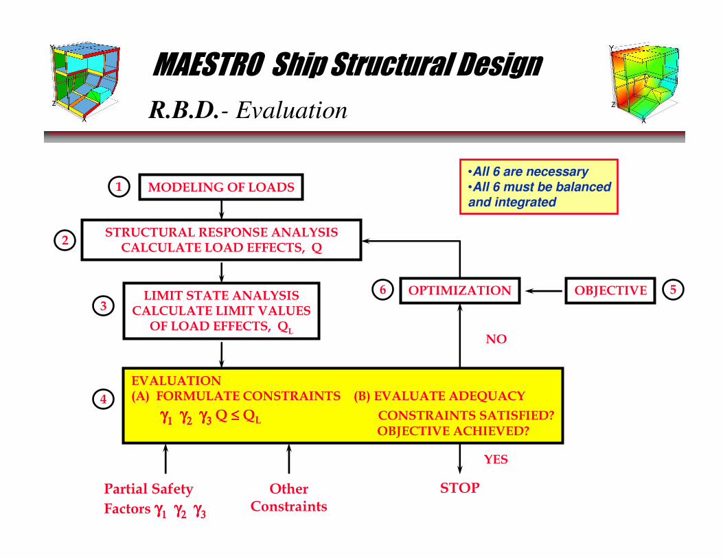
R.B.D.- Evaluation
MODELING OF LOADS
STRUCTURAL RESPONSE ANALYSISCALCULATE LOAD EFFECTS, Q
LIMIT STATE ANALYSISCALCULATE LIMIT VALUES
OF LOAD EFFECTS, QL
OPTIMIZATION OBJECTIVE
1
OtherConstraints
YES
STOP
NO
Partial Safety
Factors γγγγ1111 γγγγ2222 γγγγ3333
EVALUATION(A) FORMULATE CONSTRAINTS (B) EVALUATE ADEQUACY
γγγγ1111 γγγγ2222 γγγγ3333 Q ≤≤≤≤ QL CONSTRAINTS SATISFIED?OBJECTIVE ACHIEVED?
2
3
4
56
•All 6 are necessary•All 6 must be balancedand integrated

MAESTRO Ship Structural Design
R.B.D.-Evaluation: Formulate Constraints
RESPONSE ANALYSISRESPONSE ANALYSIS
Q
LIMIT ANALYSISLIMIT ANALYSIS
Q L
γ Q Q L≤
Partial SafetyFactors
γγγγ1111 γγγγ2222 γγγγ3333 ==== γγγγ
MAESTRO Ship Structural Design
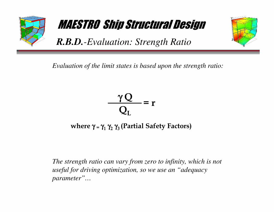
R.B.D.-Evaluation: Strength Ratio
γ γ γ γ Q
QL
= r
where γ γ γ γ ==== γγγγ1111 γγγγ2222 γγγγ3 3 3 3 (Partial Safety Factors)
Evaluation of the limit states is based upon the strength ratio:
The strength ratio can vary from zero to infinity, which is not
useful for driving optimization, so we use an “adequacy
parameter”…

MAESTRO Ship Structural Design
R.B.D.-Evaluation: Adequacy Parameter
1 - r
1 + r = g
The adequacy parameter, “g”:
This parameter varies from -1 to +1. Zero indicates that the
structure, under the defined loads, is optimum for that
particular limit state. Negative values indicate that the
structure’s response, with the user defined safety factors,
exceeds the limit state.
MAESTRO Ship Structural Design
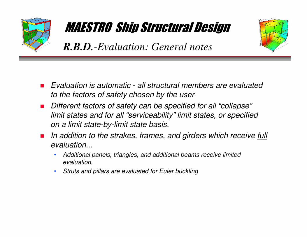
R.B.D.-Evaluation: General notes
� Evaluation is automatic - all structural members are evaluated to the factors of safety chosen by the user
� Different factors of safety can be specified for all “collapse”limit states and for all “serviceability” limit states, or specified on a limit state-by-limit state basis.
� In addition to the strakes, frames, and girders which receive fullevaluation...
• Additional panels, triangles, and additional beams receive limited
evaluation,
• Struts and pillars are evaluated for Euler buckling
MAESTRO Ship Structural Design
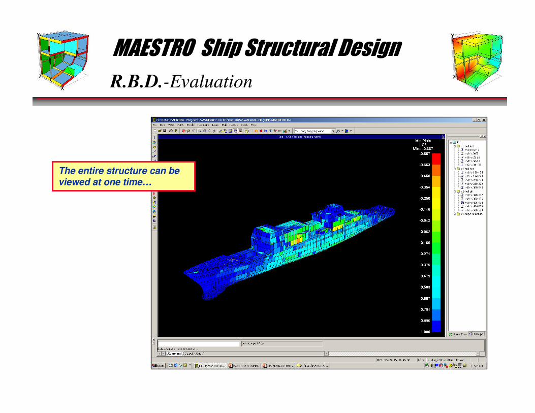
R.B.D.-Evaluation
The entire structure can be viewed at one time…
MAESTRO Ship Structural Design
R.B.D.-Evaluation
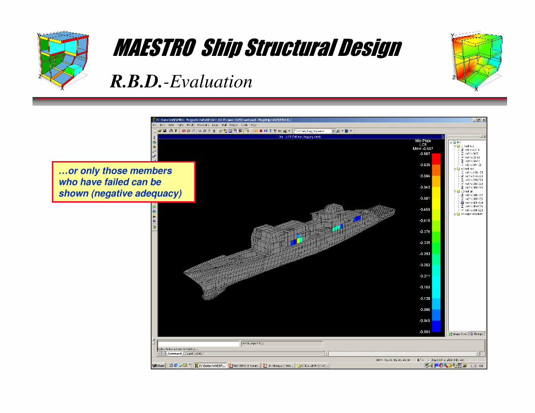
…or only those members who have failed can be shown (negative adequacy)
MAESTRO Ship Structural Design
R.B.D.-Evaluation
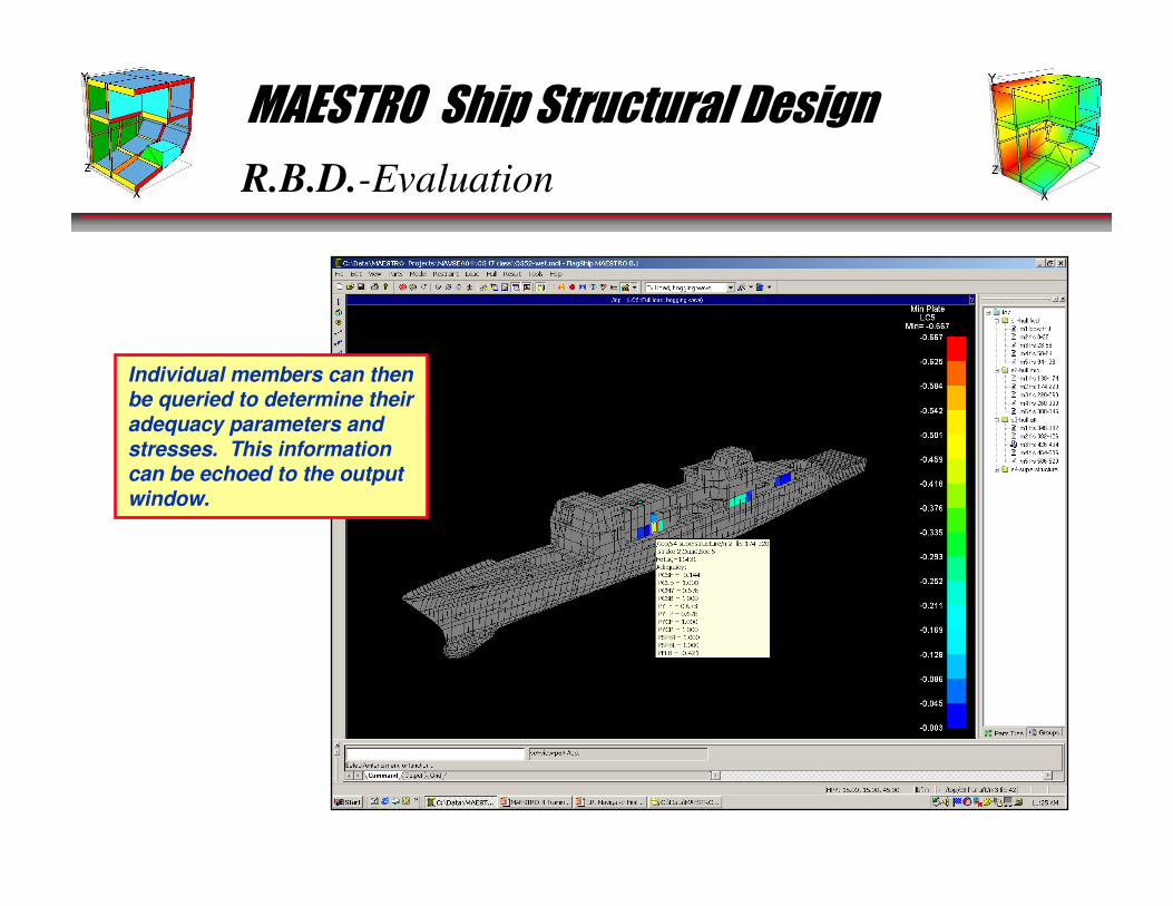
Individual members can then be queried to determine their adequacy parameters and stresses. This information can be echoed to the output window.

MAESTRO Ship Structural Design
R.B.D.- Optimization Objective
MODELING OF LOADS
STRUCTURAL RESPONSE ANALYSISCALCULATE LOAD EFFECTS, Q
LIMIT STATE ANALYSISCALCULATE LIMIT VALUES
OF LOAD EFFECTS, QL
OPTIMIZATION OBJECTIVE
1
OtherConstraints
YES
STOP
NO
Partial Safety
Factors γγγγ1111 γγγγ2222 γγγγ3333
EVALUATION(A) FORMULATE CONSTRAINTS (B) EVALUATE ADEQUACY
γγγγ1111 γγγγ2222 γγγγ3333 Q ≤≤≤≤ QL CONSTRAINTS SATISFIED?OBJECTIVE ACHIEVED?
2
3
4
56
•All 6 are necessary•All 6 must be balancedand integrated
MAESTRO Ship Structural Design
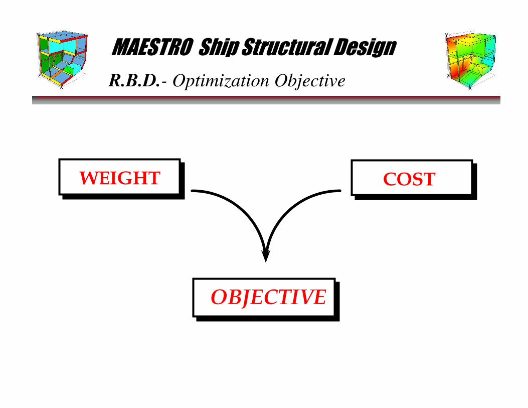
R.B.D.- Optimization Objective
COSTWEIGHT
OBJECTIVE
MAESTRO Ship Structural Design
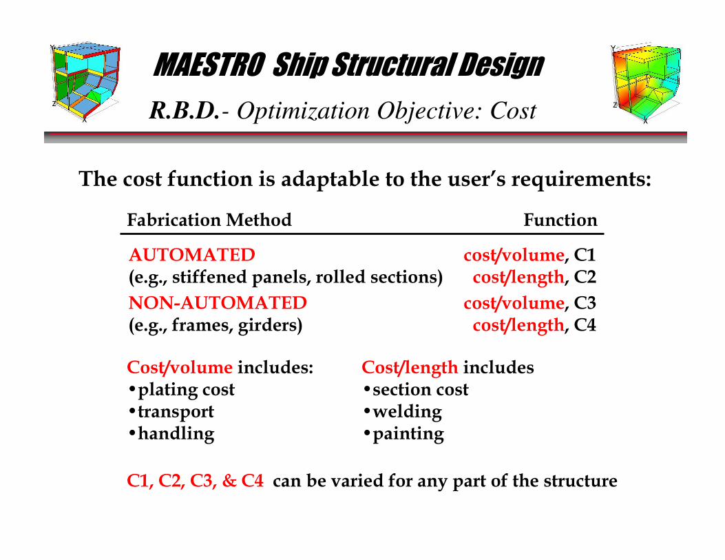
R.B.D.- Optimization Objective: Cost
The cost function is adaptable to the user’s requirements:
Fabrication Method Function
AUTOMATED(e.g., stiffened panels, rolled sections)
NON-AUTOMATED(e.g., frames, girders)
cost/volume, C1cost/length, C2
cost/volume, C3cost/length, C4
Cost/volume includes:•plating cost•transport•handling
Cost/length includes•section cost•welding•painting
C1, C2, C3, & C4 can be varied for any part of the structure
MAESTRO Ship Structural Design
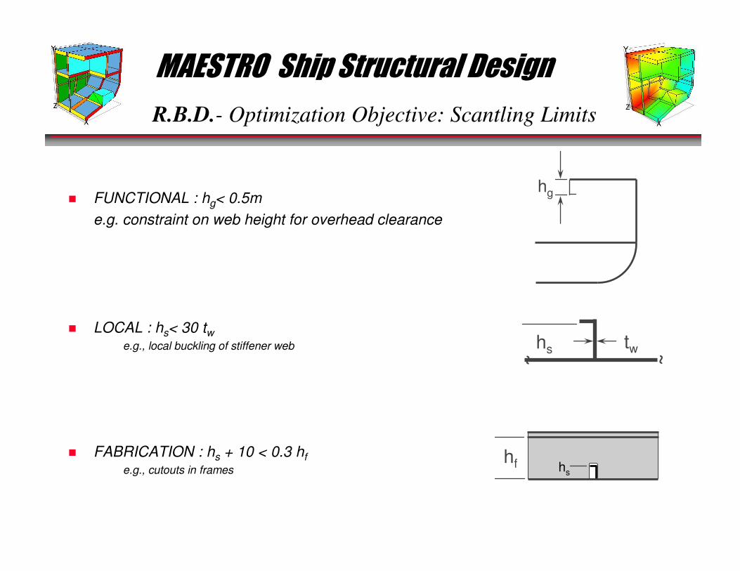
R.B.D.- Optimization Objective: Scantling Limits
� FUNCTIONAL : hg< 0.5m
e.g. constraint on web height for overhead clearance
� LOCAL : hs< 30 tw• e.g., local buckling of stiffener web
� FABRICATION : hs + 10 < 0.3 hf
• e.g., cutouts in frames
~~
hs tw
hg
hs
hf

MAESTRO Ship Structural Design
R.B.D.- Optimization Objective: Scantling Limits
The user defines the desired limits on the scantlings (left) as well as proportional limits on plating, stiffeners, and beams (above)
MAESTRO Ship Structural Design
R.B.D.- Optimization Objective
MODELING OF LOADS
STRUCTURAL RESPONSE ANALYSISCALCULATE LOAD EFFECTS, Q
LIMIT STATE ANALYSISCALCULATE LIMIT VALUES
OF LOAD EFFECTS, QL
OPTIMIZATION OBJECTIVE
1
OtherConstraints
YES
STOP
NO
Partial Safety
Factors γγγγ1111 γγγγ2222 γγγγ3333
EVALUATION(A) FORMULATE CONSTRAINTS (B) EVALUATE ADEQUACY
γγγγ1111 γγγγ2222 γγγγ3333 Q ≤≤≤≤ QL CONSTRAINTS SATISFIED?OBJECTIVE ACHIEVED?
2
3
4
56
•All 6 are necessary•All 6 must be balancedand integrated
MAESTRO Ship Structural Design
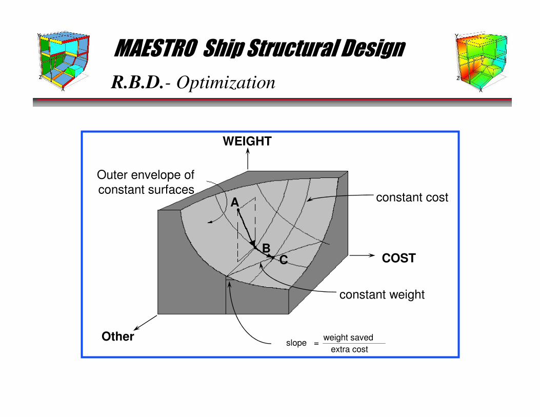
R.B.D.- Optimization
Other
WEIGHT
COST
Outer envelope of
constant surfacesA
BC
constant weight
constant cost
slope =weight saved
extra cost
MAESTRO Ship Structural Design
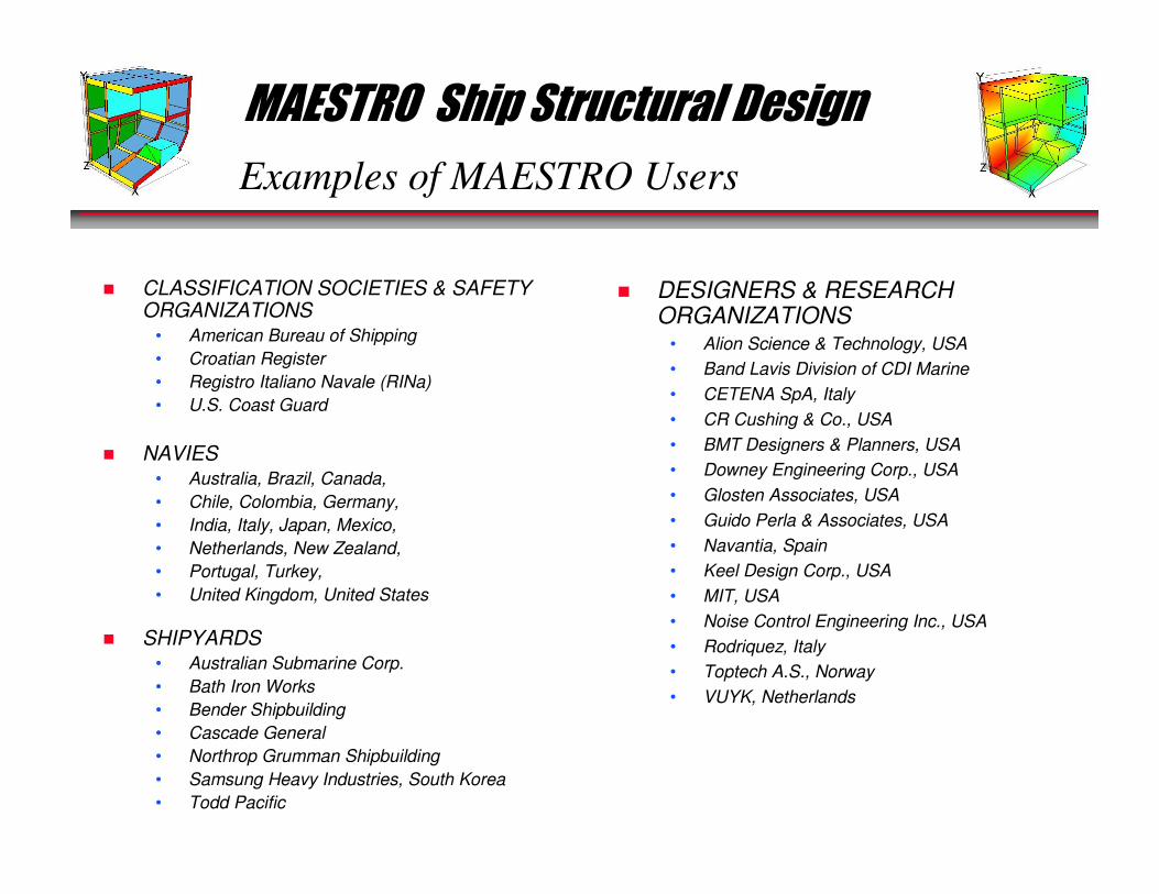
Examples of MAESTRO Users
� CLASSIFICATION SOCIETIES & SAFETY ORGANIZATIONS
• American Bureau of Shipping
• Croatian Register
• Registro Italiano Navale (RINa)
• U.S. Coast Guard
� NAVIES• Australia, Brazil, Canada,
• Chile, Colombia, Germany,
• India, Italy, Japan, Mexico,
• Netherlands, New Zealand,
• Portugal, Turkey,
• United Kingdom, United States
� SHIPYARDS• Australian Submarine Corp.
• Bath Iron Works
• Bender Shipbuilding
• Cascade General
• Northrop Grumman Shipbuilding
• Samsung Heavy Industries, South Korea
• Todd Pacific
� DESIGNERS & RESEARCH ORGANIZATIONS
• Alion Science & Technology, USA
• Band Lavis Division of CDI Marine
• CETENA SpA, Italy
• CR Cushing & Co., USA
• BMT Designers & Planners, USA
• Downey Engineering Corp., USA
• Glosten Associates, USA
• Guido Perla & Associates, USA
• Navantia, Spain
• Keel Design Corp., USA
• MIT, USA
• Noise Control Engineering Inc., USA
• Rodriquez, Italy
• Toptech A.S., Norway
• VUYK, Netherlands
MAESTRO Ship Structural Design
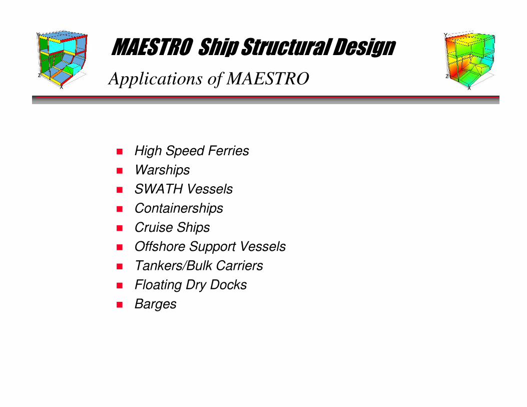
Applications of MAESTRO
� High Speed Ferries
� Warships
� SWATH Vessels
� Containerships
� Cruise Ships
� Offshore Support Vessels
� Tankers/Bulk Carriers
� Floating Dry Docks
� Barges
MAESTRO Ship Structural Design
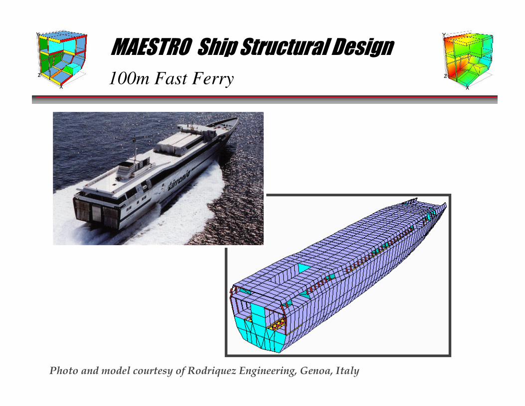
100m Fast Ferry
Photo and model courtesy of Rodriquez Engineering, Genoa, Italy
MAESTRO Ship Structural Design
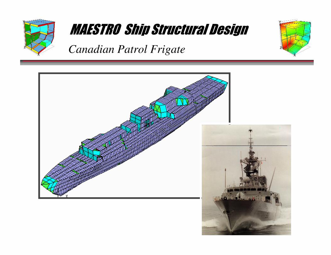
Canadian Patrol Frigate
MAESTRO Ship Structural Design
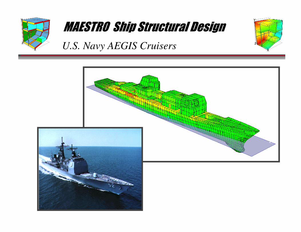
U.S. Navy AEGIS Cruisers
MAESTRO Ship Structural Design
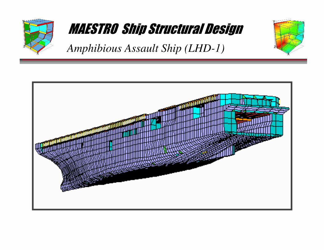
Amphibious Assault Ship (LHD-1)
MAESTRO Ship Structural Design
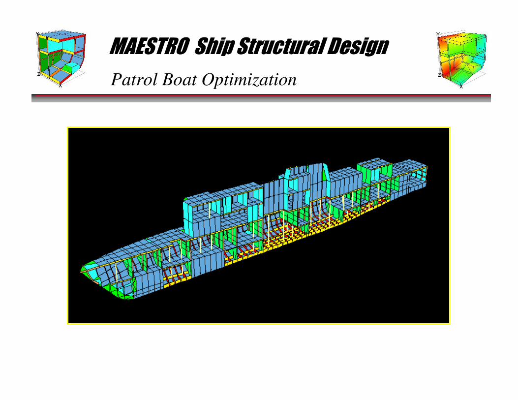
Patrol Boat Optimization
MAESTRO Ship Structural Design
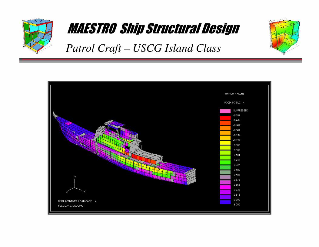
Patrol Craft – USCG Island Class
MAESTRO Ship Structural Design
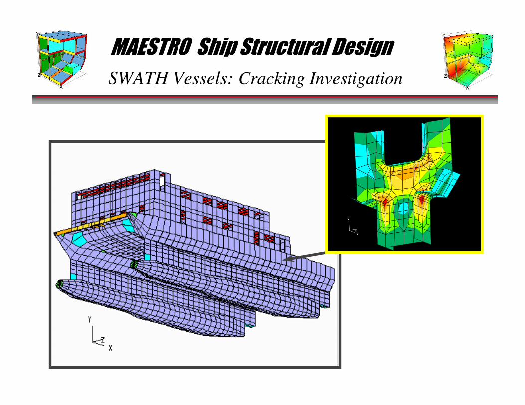
SWATH Vessels: Cracking Investigation
X
Y
Z
X
Y
Z
MAESTRO Ship Structural Design
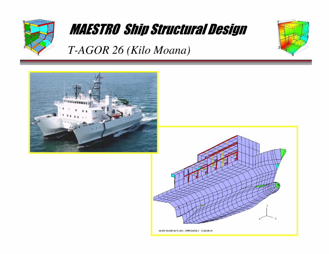
T-AGOR 26 (Kilo Moana)

MAESTRO Ship Structural Design
5500 TEU Containership
MAESTRO Ship Structural Design
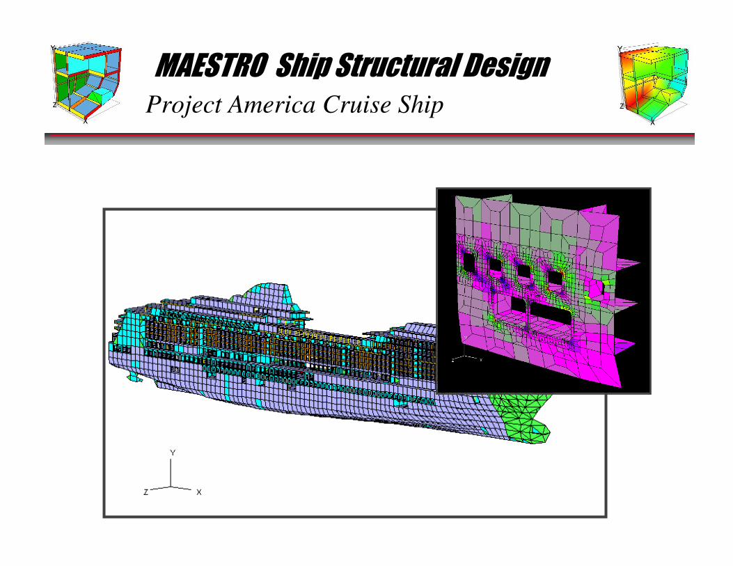
Project America Cruise Ship
MAESTRO Ship Structural Design
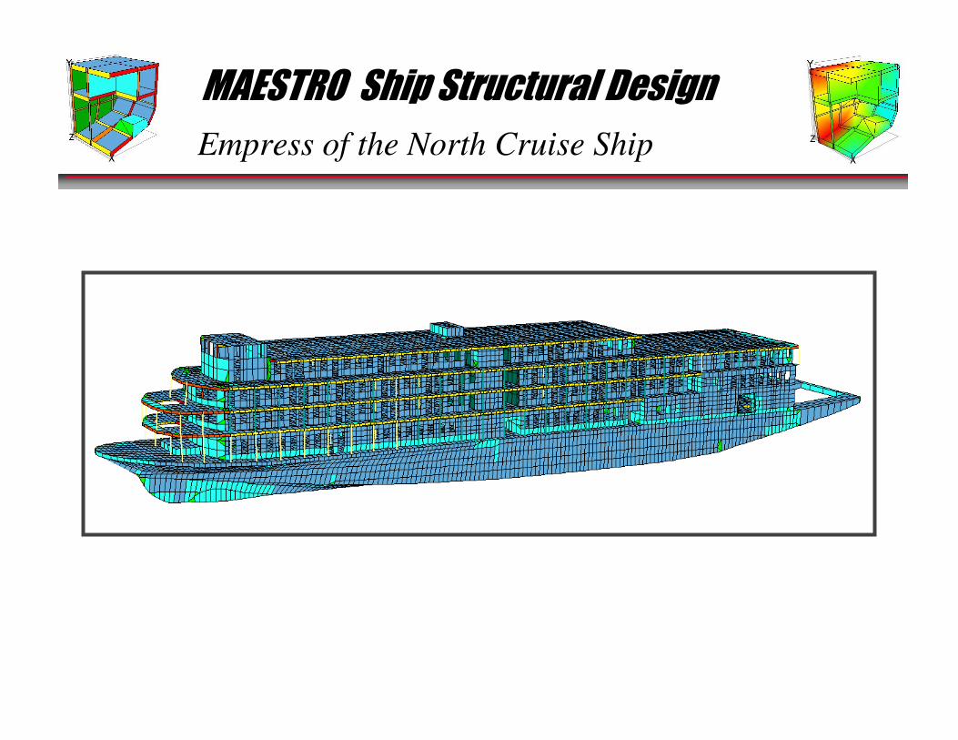
Empress of the North Cruise Ship

MAESTRO Ship Structural Design
OSV Analysis
MAESTRO Ship Structural Design
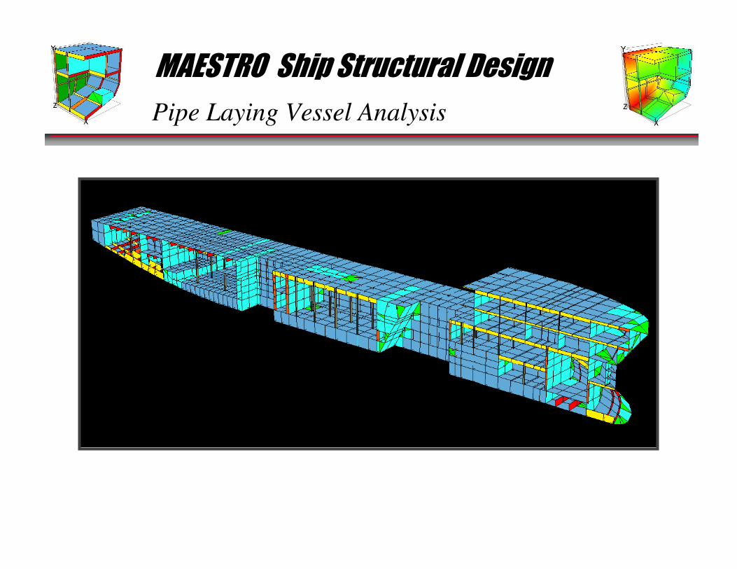
Pipe Laying Vessel Analysis

MAESTRO Ship Structural Design
Floating Dry Dock
MAESTRO Ship Structural Design
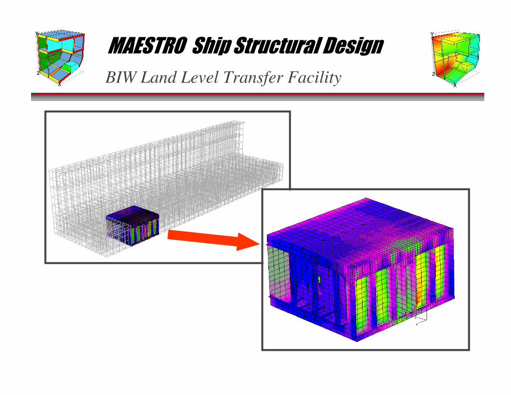
BIW Land Level Transfer Facility
MAESTRO Ship Structural Design
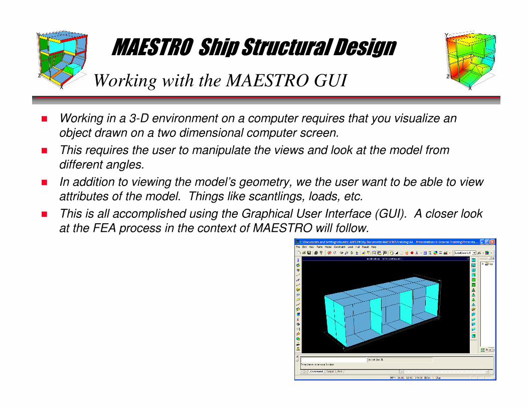
Working with the MAESTRO GUI
� Working in a 3-D environment on a computer requires that you visualize an
object drawn on a two dimensional computer screen.
� This requires the user to manipulate the views and look at the model from
different angles.
� In addition to viewing the model’s geometry, we the user want to be able to view
attributes of the model. Things like scantlings, loads, etc.
� This is all accomplished using the Graphical User Interface (GUI). A closer look
at the FEA process in the context of MAESTRO will follow.
MAESTRO Ship Structural Design
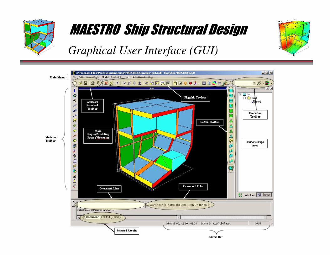
Graphical User Interface (GUI)
MAESTRO Ship Structural Design
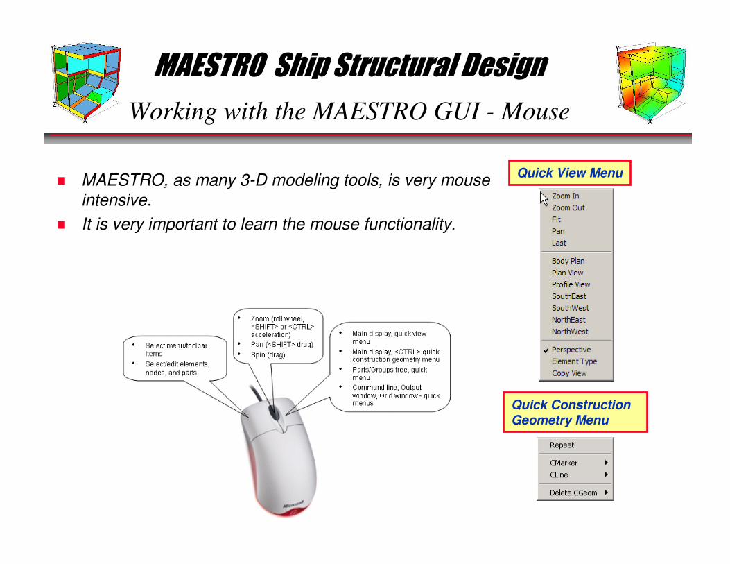
Working with the MAESTRO GUI - Mouse
� MAESTRO, as many 3-D modeling tools, is very mouse
intensive.
� It is very important to learn the mouse functionality.
Quick View Menu
Quick Construction Geometry Menu
MAESTRO Ship Structural Design
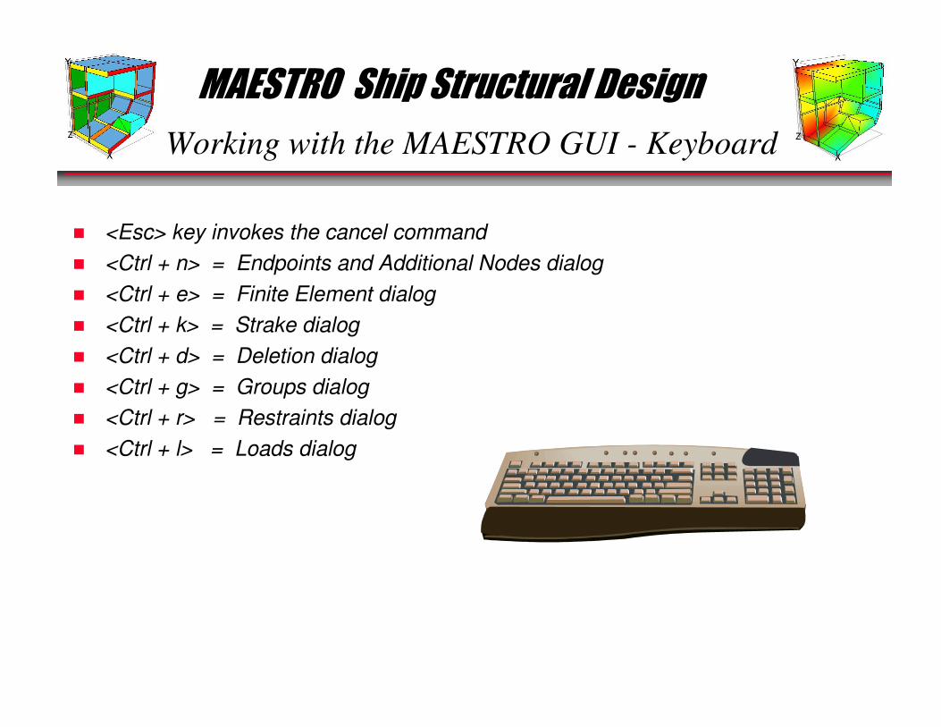
Working with the MAESTRO GUI - Keyboard
� <Esc> key invokes the cancel command
� <Ctrl + n> = Endpoints and Additional Nodes dialog
� <Ctrl + e> = Finite Element dialog
� <Ctrl + k> = Strake dialog
� <Ctrl + d> = Deletion dialog
� <Ctrl + g> = Groups dialog
� <Ctrl + r> = Restraints dialog
� <Ctrl + l> = Loads dialog
MAESTRO Ship Structural Design
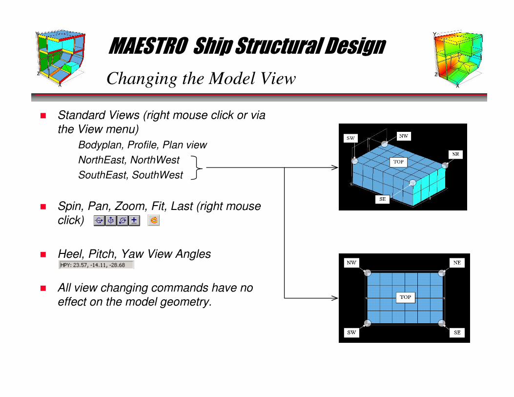
Changing the Model View
� Standard Views (right mouse click or via
the View menu)
• Bodyplan, Profile, Plan view
• NorthEast, NorthWest
• SouthEast, SouthWest
� Spin, Pan, Zoom, Fit, Last (right mouse
click)
� Heel, Pitch, Yaw View Angles
� All view changing commands have no
effect on the model geometry.
MAESTRO Ship Structural Design
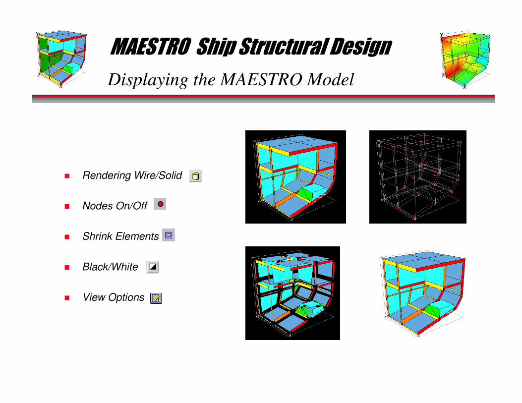
Displaying the MAESTRO Model
� Rendering Wire/Solid
� Nodes On/Off
� Shrink Elements
� Black/White
� View Options
MAESTRO Ship Structural Design
Displaying the MAESTRO Model
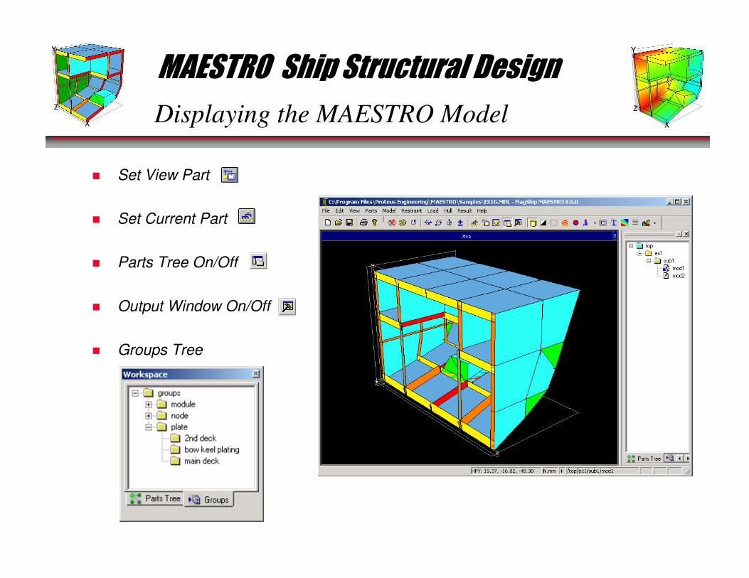
� Set View Part
� Set Current Part
� Parts Tree On/Off
� Output Window On/Off
� Groups Tree
MAESTRO Ship Structural Design
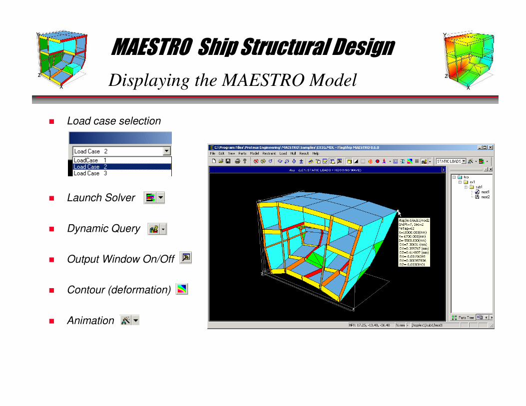
Displaying the MAESTRO Model
� Load case selection
� Launch Solver
� Dynamic Query
� Output Window On/Off
� Contour (deformation)
� Animation
MAESTRO Ship Structural Design
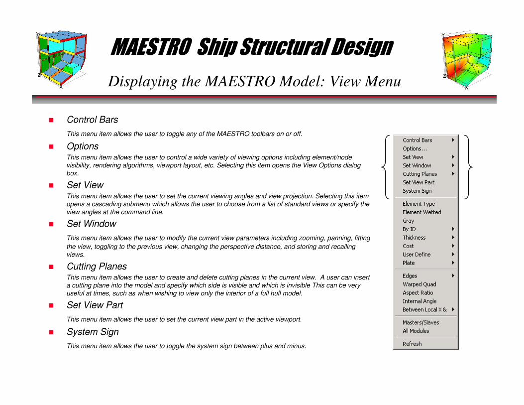
Displaying the MAESTRO Model: View Menu
� Control Bars
This menu item allows the user to toggle any of the MAESTRO toolbars on or off.
� OptionsThis menu item allows the user to control a wide variety of viewing options including element/node
visibility, rendering algorithms, viewport layout, etc. Selecting this item opens the View Options dialog
box.
� Set ViewThis menu item allows the user to set the current viewing angles and view projection. Selecting this item
opens a cascading submenu which allows the user to choose from a list of standard views or specify the
view angles at the command line.
� Set Window
This menu item allows the user to modify the current view parameters including zooming, panning, fitting
the view, toggling to the previous view, changing the perspective distance, and storing and recalling
views.
� Cutting PlanesThis menu item allows the user to create and delete cutting planes in the current view. A user can insert
a cutting plane into the model and specify which side is visible and which is invisible This can be very
useful at times, such as when wishing to view only the interior of a full hull model.
� Set View Part
This menu item allows the user to set the current view part in the active viewport.
� System Sign
This menu item allows the user to toggle the system sign between plus and minus.
MAESTRO Ship Structural Design
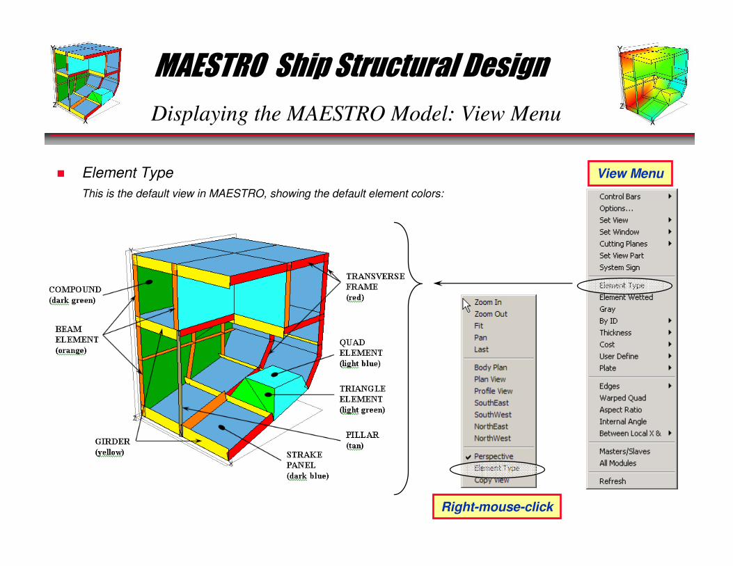
Displaying the MAESTRO Model: View Menu
� Element Type
This is the default view in MAESTRO, showing the default element colors:
View Menu
Right-mouse-click
MAESTRO Ship Structural Design
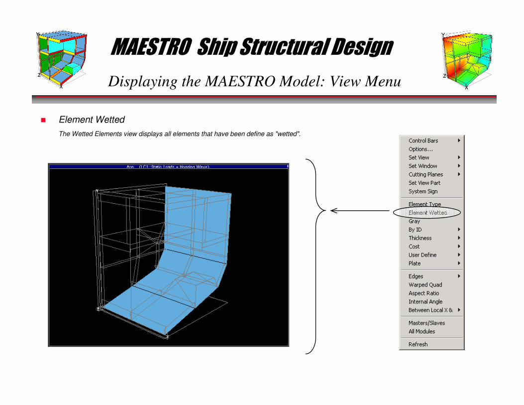
Displaying the MAESTRO Model: View Menu
� Element Wetted
The Wetted Elements view displays all elements that have been define as "wetted".

MAESTRO Ship Structural Design
Displaying the MAESTRO Model: View Menu
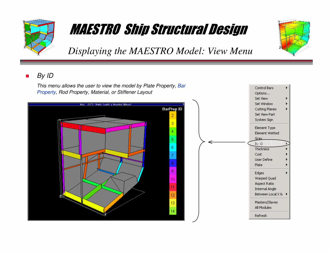
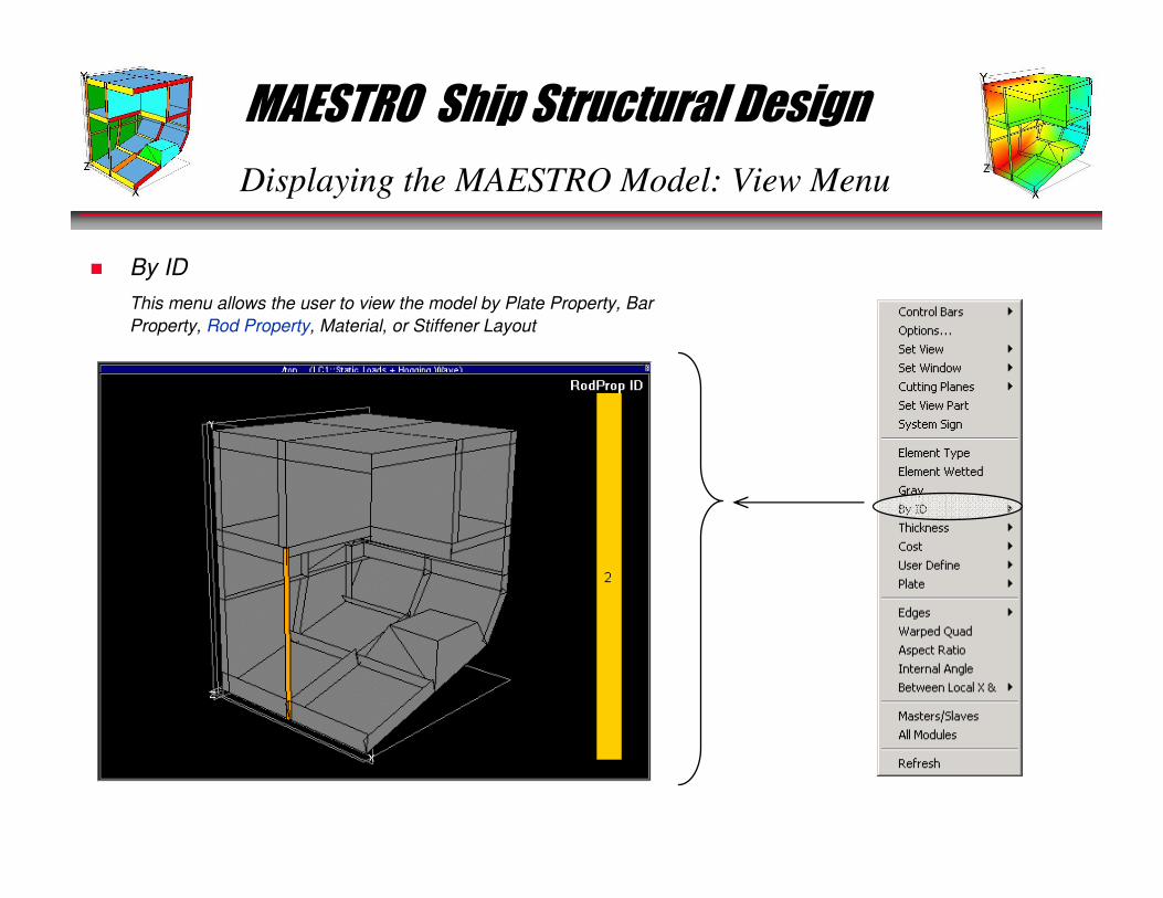
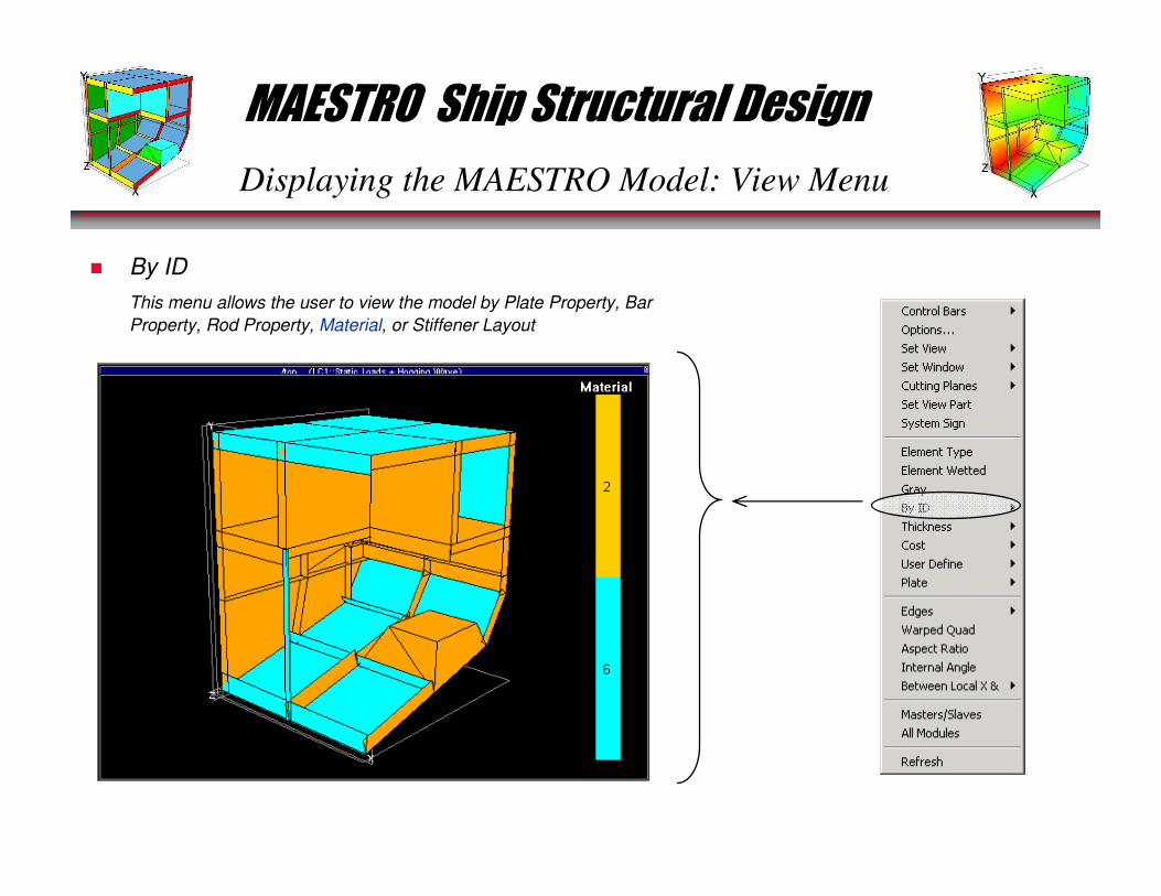
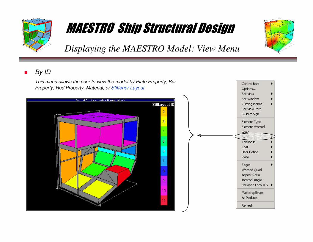
� By ID
This menu allows the user to view the model by Plate Property, Bar
Property, Rod Property, Material, or Stiffener Layout
MAESTRO Ship Structural Design
Displaying the MAESTRO Model: View Menu
� By ID
This menu allows the user to view the model by Plate Property, Bar
Property, Rod Property, Material, or Stiffener Layout
MAESTRO Ship Structural Design
Displaying the MAESTRO Model: View Menu
� By ID
This menu allows the user to view the model by Plate Property, Bar
Property, Rod Property, Material, or Stiffener Layout
MAESTRO Ship Structural Design
Displaying the MAESTRO Model: View Menu
� By ID
This menu allows the user to view the model by Plate Property, Bar
Property, Rod Property, Material, or Stiffener Layout
MAESTRO Ship Structural Design
Displaying the MAESTRO Model: View Menu
� By ID
This menu allows the user to view the model by Plate Property, Bar
Property, Rod Property, Material, or Stiffener Layout
MAESTRO Ship Structural Design
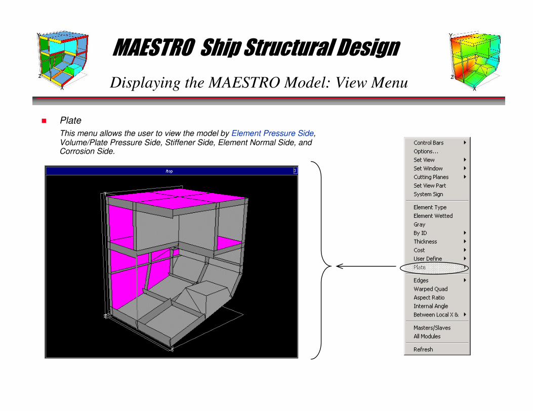
Displaying the MAESTRO Model: View Menu
� Plate
This menu allows the user to view the model by Element Pressure Side, Volume/Plate Pressure Side, Stiffener Side, Element Normal Side, and Corrosion Side.

MAESTRO Ship Structural Design
Displaying the MAESTRO Model: View Menu
� Plate
This menu allows the user to view the model by Element Pressure
Side, Volume/Plate Pressure Side, Stiffener Side, Element Normal
Side, and Corrosion Side.
MAESTRO Ship Structural Design
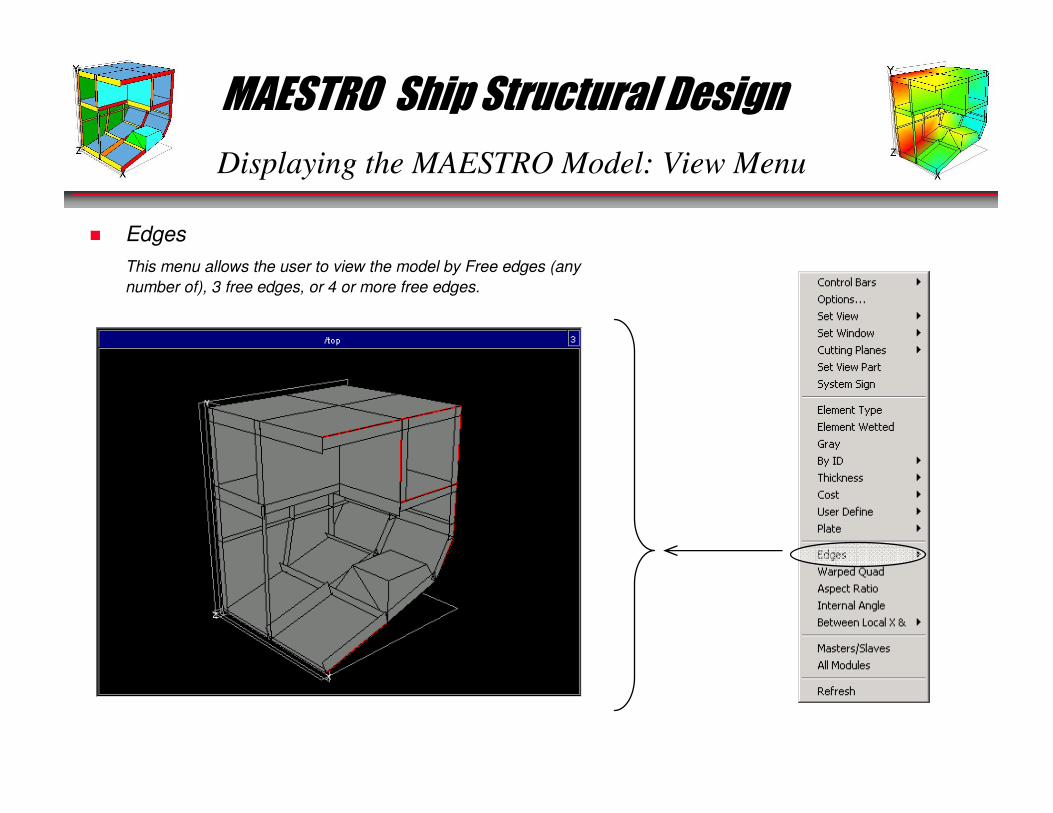
Displaying the MAESTRO Model: View Menu
� Edges
This menu allows the user to view the model by Free edges (any
number of), 3 free edges, or 4 or more free edges.
MAESTRO Ship Structural Design
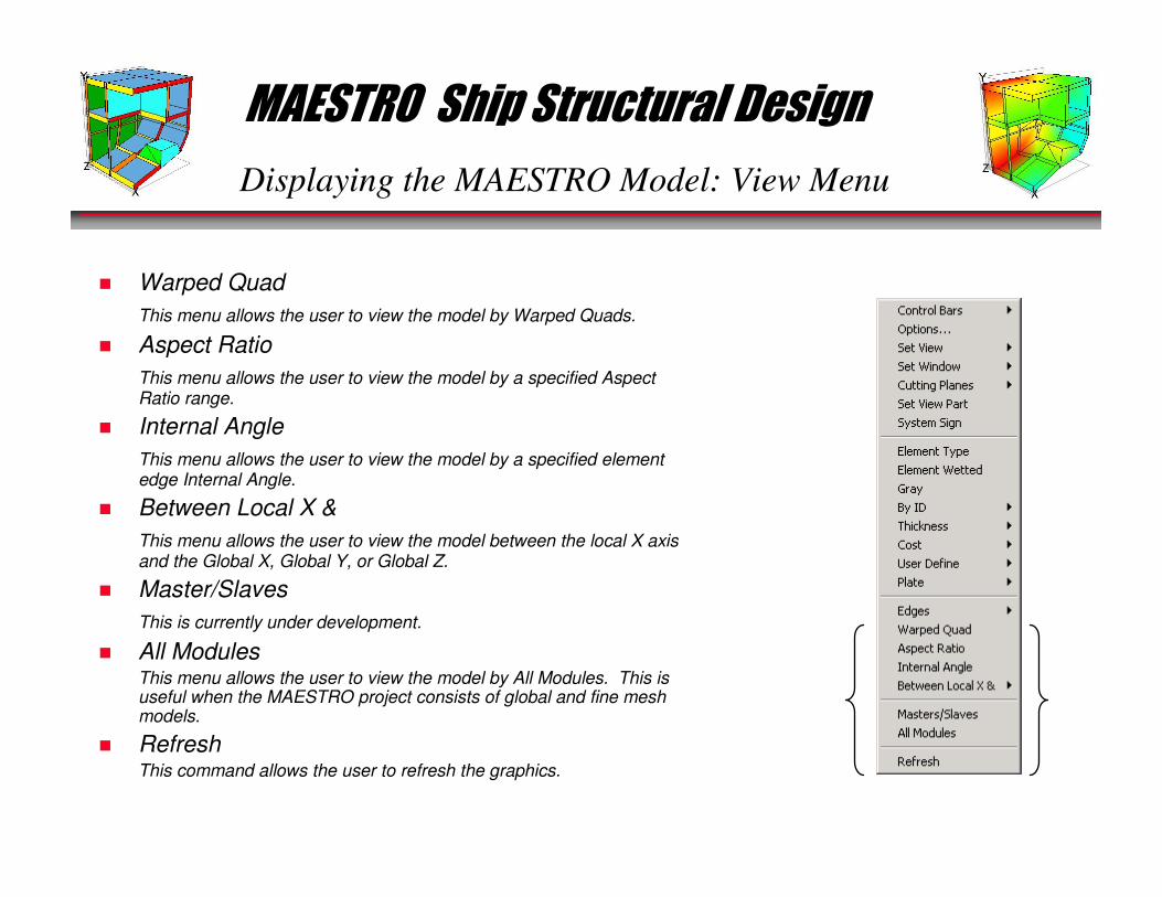
Displaying the MAESTRO Model: View Menu
� Warped Quad
This menu allows the user to view the model by Warped Quads.
� Aspect Ratio
This menu allows the user to view the model by a specified Aspect Ratio range.
� Internal Angle
This menu allows the user to view the model by a specified element edge Internal Angle.
� Between Local X &
This menu allows the user to view the model between the local X axis and the Global X, Global Y, or Global Z.
� Master/Slaves
This is currently under development.
� All ModulesThis menu allows the user to view the model by All Modules. This is useful when the MAESTRO project consists of global and fine meshmodels.
� RefreshThis command allows the user to refresh the graphics.

MAESTRO Ship Structural Design
Displaying the MAESTRO Model: Hull Menu
� View Self Weight
The View Self Weight command under the Hull menu is used to display
the MAESTRO calculated "modeled" weight. The term "modeled"
weight refers to the weight calculated by MAESTRO based on the
materials and elements that make up the FE model. As shown below,
MAESTRO produces a display of this weight distribution.
MAESTRO Ship Structural Design
Displaying the MAESTRO Model: Hull Menu
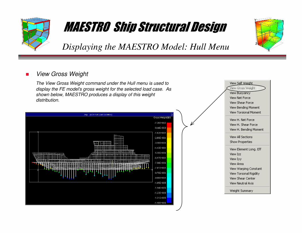
� View Gross Weight
The View Gross Weight command under the Hull menu is used to
display the FE model's gross weight for the selected load case. As
shown below, MAESTRO produces a display of this weight
distribution.

MAESTRO Ship Structural Design
Displaying the MAESTRO Model: Hull Menu
� View Buoyancy
The View Buoyancy command under the Hull menu is used to display
the FE model's buoyancy distribution for the selected load case, as
shown below.

MAESTRO Ship Structural Design
Displaying the MAESTRO Model: Hull Menu
� View Net Force
The View Net Force command under the Hull menu is used to display
the FE model's net force distribution for the selected load case, as
shown below.

MAESTRO Ship Structural Design
Displaying the MAESTRO Model: Hull Menu
� View Shear ForceThe View Shear Force command under the Hull menu is used to
display the FE model's shear force distribution, as shown below.
MAESTRO Ship Structural Design
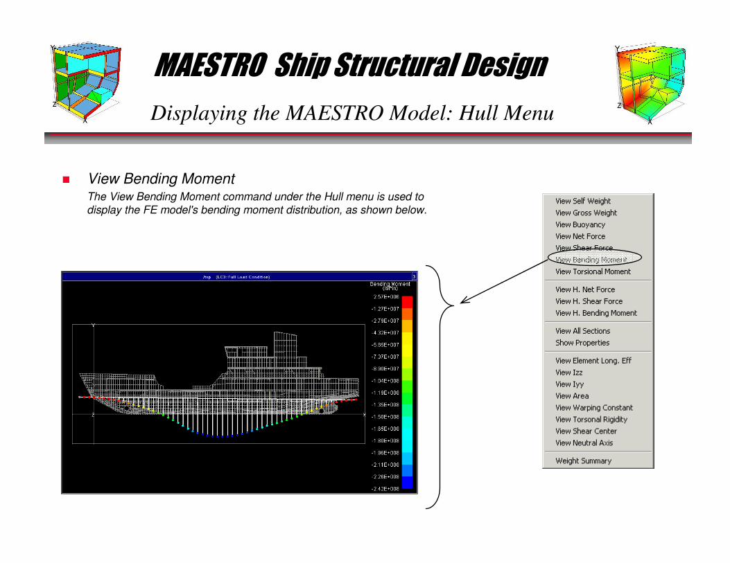
Displaying the MAESTRO Model: Hull Menu
� View Bending MomentThe View Bending Moment command under the Hull menu is used to
display the FE model's bending moment distribution, as shown below.
MAESTRO Ship Structural Design
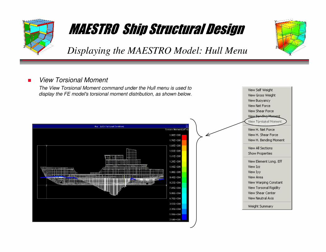
Displaying the MAESTRO Model: Hull Menu
� View Torsional MomentThe View Torsional Moment command under the Hull menu is used to
display the FE model's torsional moment distribution, as shown below.

MAESTRO Ship Structural Design
Displaying the MAESTRO Model: Hull Menu
� View H. Net and Shear Force, Bending Moment
The View H. Net Force, H. Shear Force, and H. Bending Moment
command under the Hull menu is used to display the FE model's
horizontal net force, shear force, and bending moment distribution, as
shown below.
H. Net Force H. Shear Force
H. Bending Moment
MAESTRO Ship Structural Design
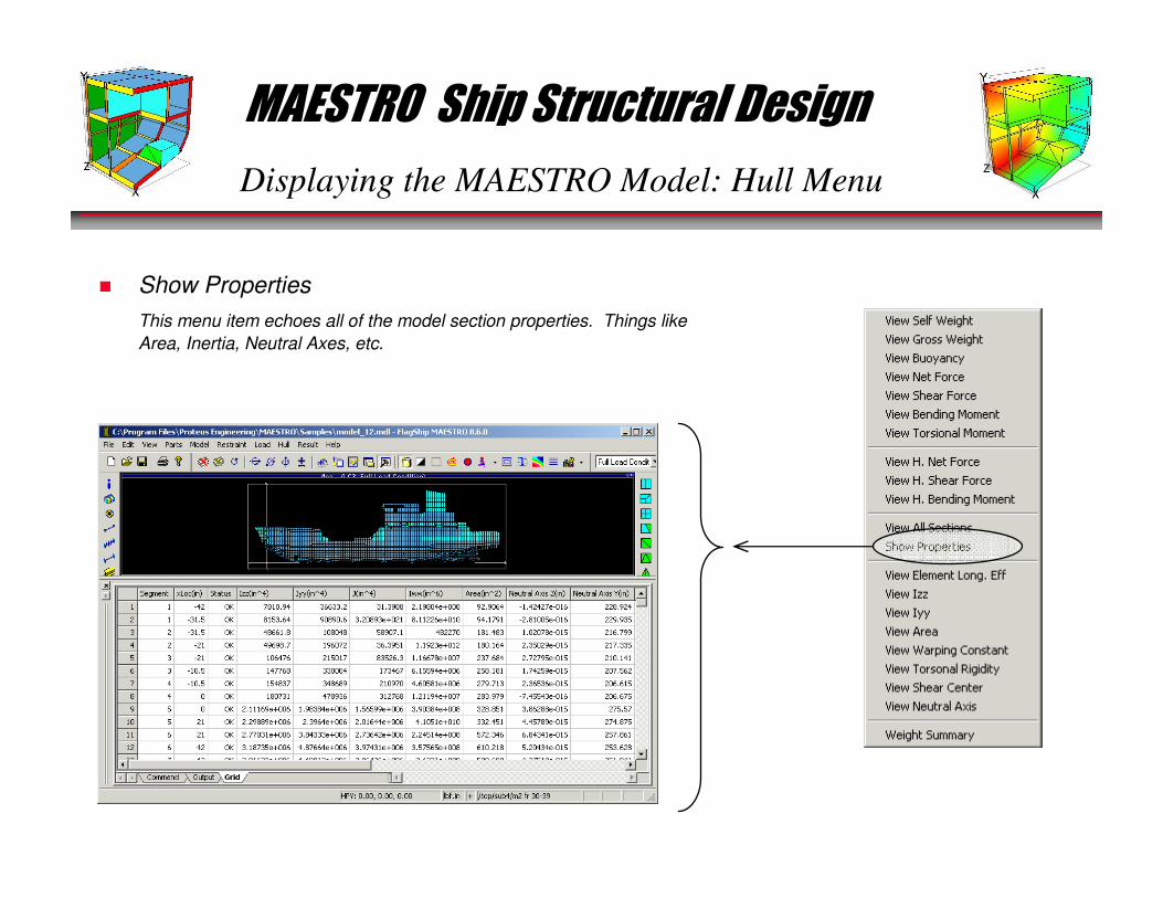
Displaying the MAESTRO Model: Hull Menu
� Show Properties
This menu item echoes all of the model section properties. Things like
Area, Inertia, Neutral Axes, etc.
MAESTRO Ship Structural Design
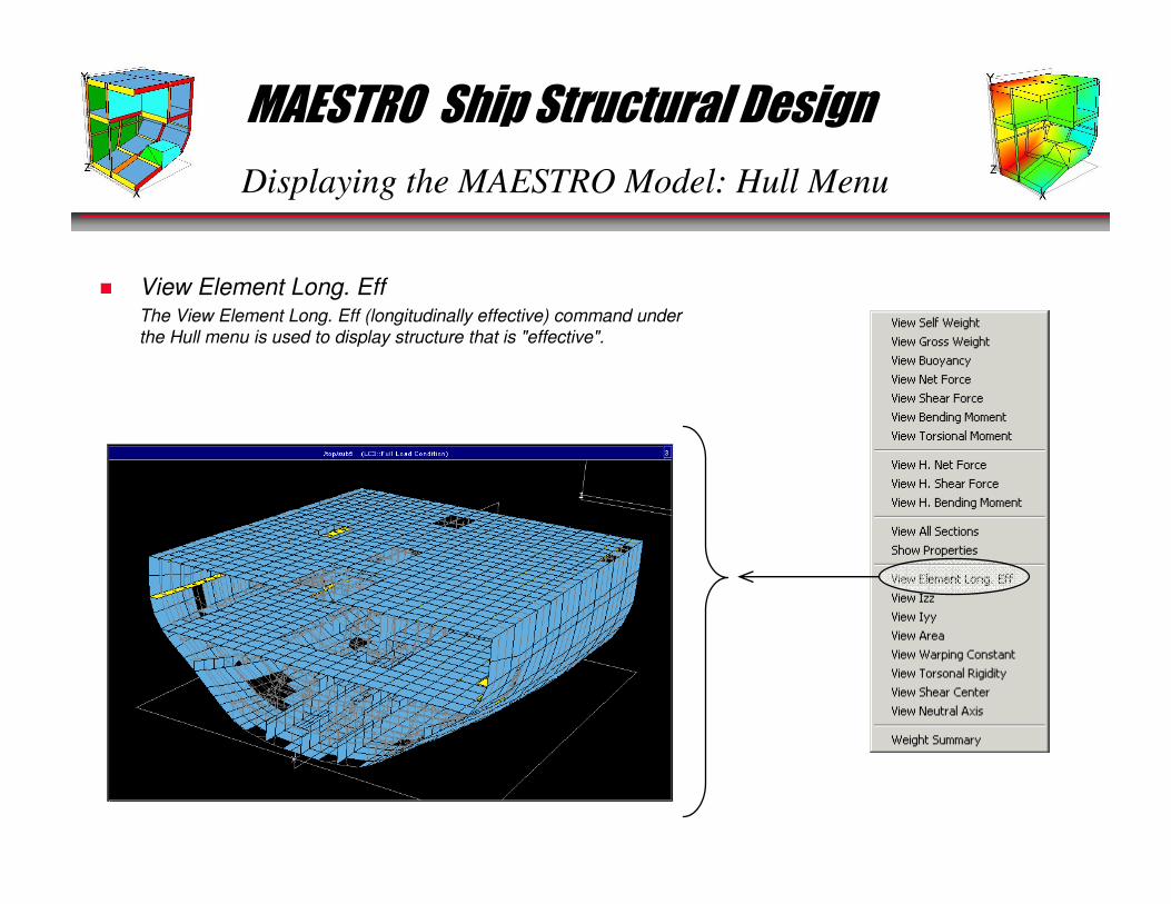
Displaying the MAESTRO Model: Hull Menu
� View Element Long. EffThe View Element Long. Eff (longitudinally effective) command under
the Hull menu is used to display structure that is "effective".
MAESTRO Ship Structural Design
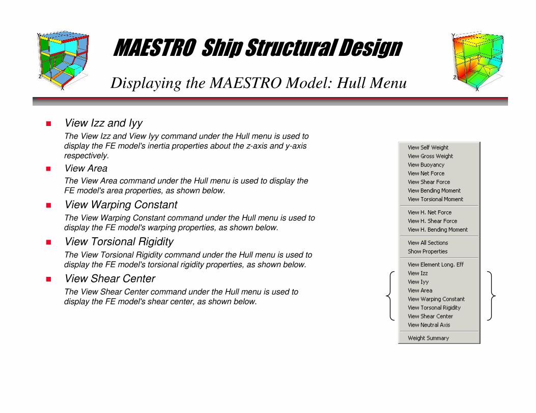
Displaying the MAESTRO Model: Hull Menu
� View Izz and IyyThe View Izz and View Iyy command under the Hull menu is used to
display the FE model's inertia properties about the z-axis and y-axis
respectively.
� View Area
The View Area command under the Hull menu is used to display the
FE model's area properties, as shown below.
� View Warping ConstantThe View Warping Constant command under the Hull menu is used todisplay the FE model's warping properties, as shown below.
� View Torsional RigidityThe View Torsional Rigidity command under the Hull menu is used to
display the FE model's torsional rigidity properties, as shown below.
� View Shear CenterThe View Shear Center command under the Hull menu is used to
display the FE model's shear center, as shown below.
MAESTRO Ship Structural Design
Displaying the MAESTRO Model: Hull Menu
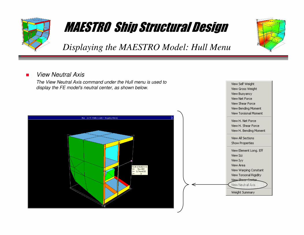
� View Neutral AxisThe View Neutral Axis command under the Hull menu is used to
display the FE model's neutral center, as shown below.
MAESTRO Ship Structural Design
Displaying the MAESTRO Model: Hull Menu
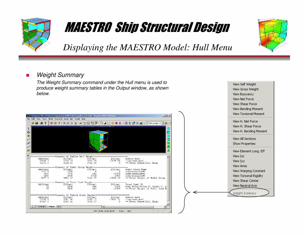
� Weight SummaryThe Weight Summary command under the Hull menu is used to
produce weight summary tables in the Output window, as shown
below.

MAESTRO Ship Structural Design
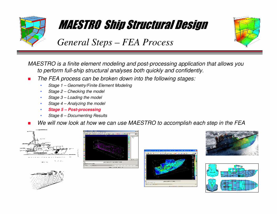
General Steps – FEA Process
MAESTRO is a finite element modeling and post-processing application that allows you
to perform full-ship structural analyses both quickly and confidently.
� The FEA process can be broken down into the following stages:• Stage 1 – Geometry/Finite Element Modeling
• Stage 2 – Checking the model
• Stage 3 – Loading the model
• Stage 4 – Analyzing the model
• Stage 5 – Post-processing
• Stage 6 – Documenting Results
� We will now look at how we can use MAESTRO to accomplish each step in the FEA
process.
MAESTRO Ship Structural Design
Geometry/FE Modeling – Stage 1
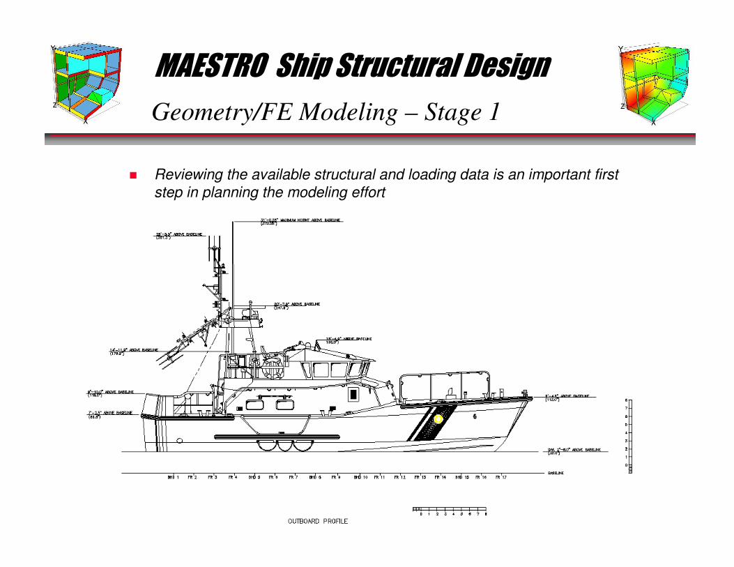
� Reviewing the available structural and loading data is an important first
step in planning the modeling effort

MAESTRO Ship Structural Design
Geometry/FE Modeling – Stage 1
� Planning your model…
MAESTRO Ship Structural Design
Geometry/FE Modeling – Stage 1
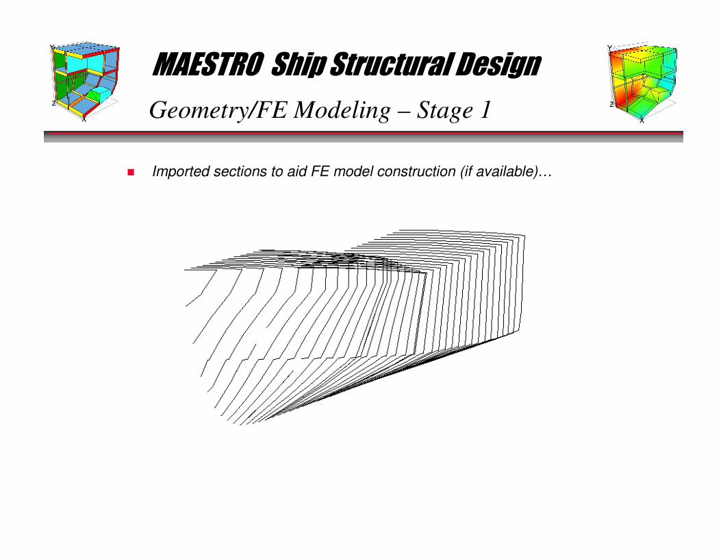
� Imported sections to aid FE model construction (if available)…
MAESTRO Ship Structural Design
Geometry/FE Modeling – Stage 1
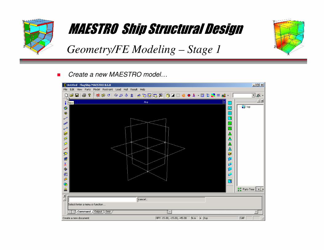
� Create a new MAESTRO model…
MAESTRO Ship Structural Design
Geometry/FE Modeling – Stage 1
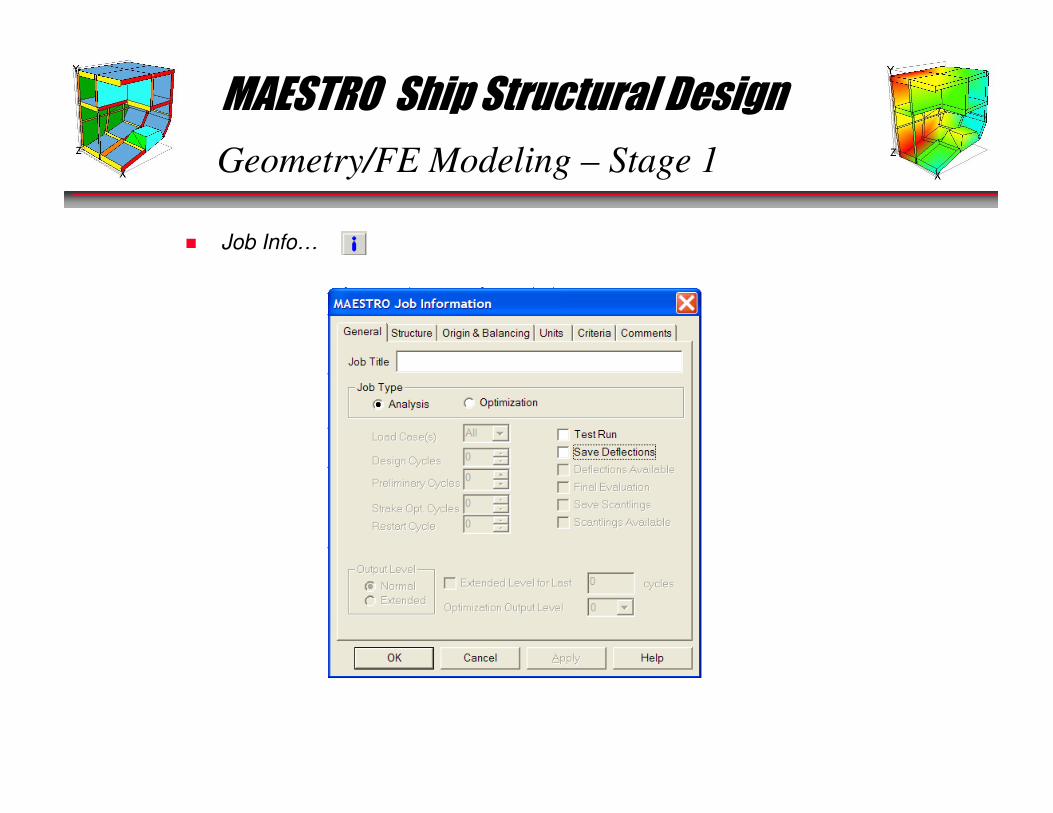
� Job Info…
MAESTRO Ship Structural Design
Geometry/FE Modeling – Stage 1
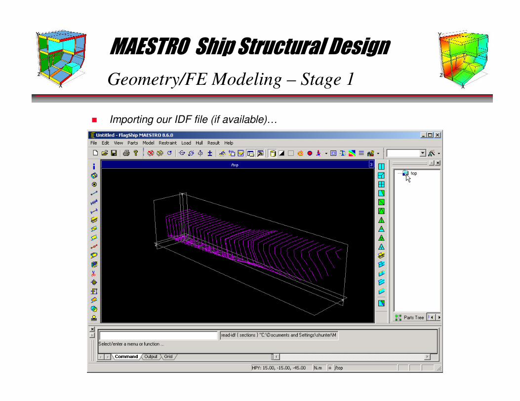
� Importing our IDF file (if available)…
MAESTRO Ship Structural Design
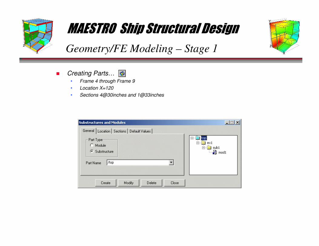
Geometry/FE Modeling – Stage 1
� Creating Parts…• Frame 4 through Frame 9
• Location X=120
• Sections 4@30inches and 1@33inches
MAESTRO Ship Structural Design
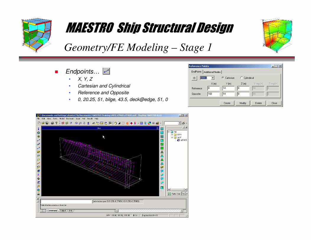
Geometry/FE Modeling – Stage 1
� Endpoints…• X, Y, Z
• Cartesian and Cylindrical
• Reference and Opposite
• 0, 20.25, 51, bilge, 43.5, deck@edge, 51, 0

MAESTRO Ship Structural Design
Geometry/FE Modeling – Stage 1
� Strakes…• General…
• Plating…
• Frames…
• Girders…
• Stiffeners…
• Deletions…
MAESTRO Ship Structural Design
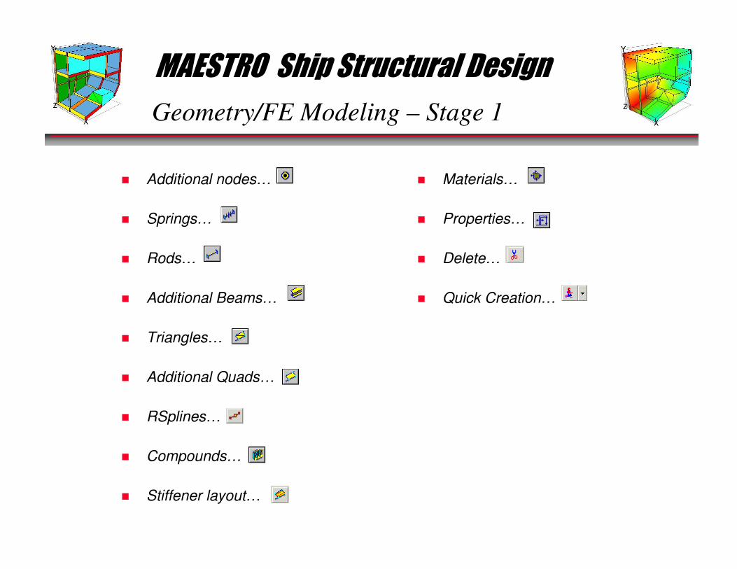
Geometry/FE Modeling – Stage 1
� Additional nodes…
� Springs…
� Rods…
� Additional Beams…
� Triangles…
� Additional Quads…
� RSplines…
� Compounds…
� Stiffener layout…
� Materials…
� Properties…
� Delete…
� Quick Creation…

MAESTRO Ship Structural Design
General Steps – FEA Process
MAESTRO is a finite element modeling and post-processing application that allows you
to perform full-ship structural analyses both quickly and confidently.
� The FEA process can be broken down into the following stages:• Stage 1 – Geometry/Finite Element Modeling
• Stage 2 – Checking the model
• Stage 3 – Loading the model
• Stage 4 – Analyzing the model
• Stage 5 – Post-processing
• Stage 6 – Documenting Results
� We will now look at how we can use MAESTRO to accomplish each step in the FEA
process.
MAESTRO Ship Structural Design
Checking the Model – Stage 2
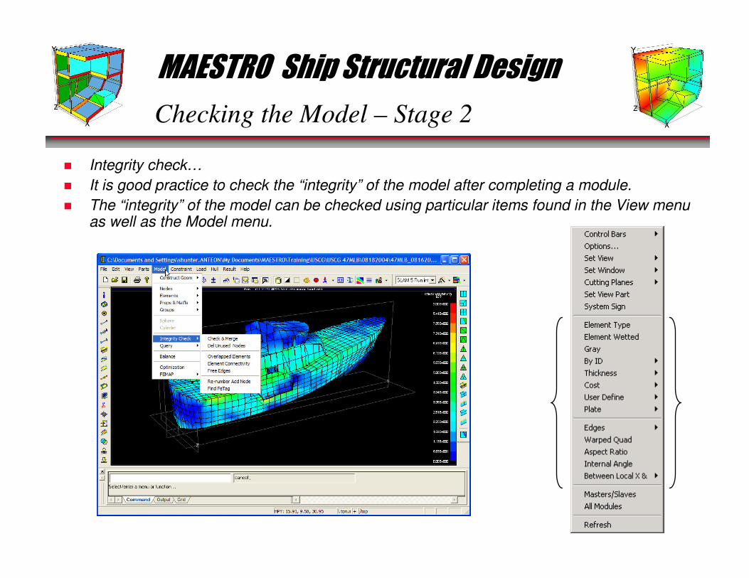
� Integrity check…
� It is good practice to check the “integrity” of the model after completing a module.
� The “integrity” of the model can be checked using particular items found in the View menu as well as the Model menu.
MAESTRO Ship Structural Design
Checking the Model – Stage 2
� After a module has been completed it is usually advisable to make a “test run”, which serves to check the model.
� This may require some further data: boundary conditions, loads and, if any loads involve acceleration, the definition of masses.
� We will now discuss boundary conditions and constraints
MAESTRO Ship Structural Design
Checking the Model – Stage 2
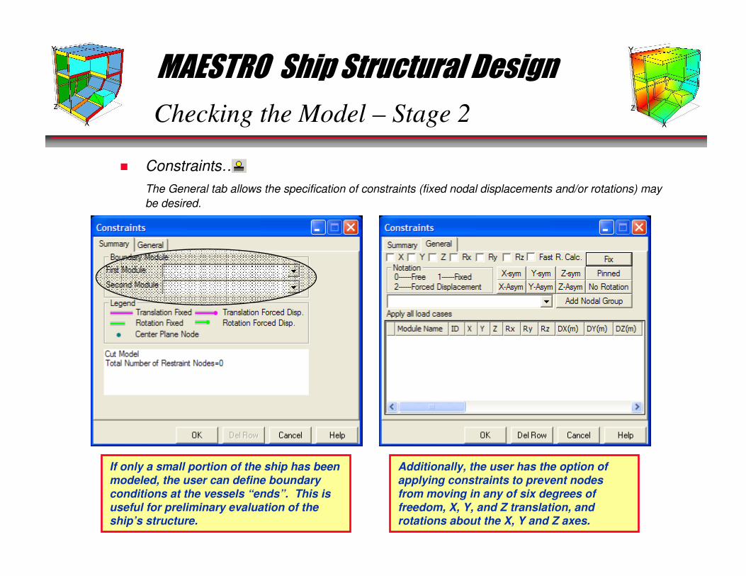
� Constraints…
The General tab allows the specification of constraints (fixed nodal displacements and/or rotations) may
be desired.
If only a small portion of the ship has been modeled, the user can define boundary
conditions at the vessels “ends”. This is
useful for preliminary evaluation of the ship’s structure.
Additionally, the user has the option of applying constraints to prevent nodes
from moving in any of six degrees of
freedom, X, Y, and Z translation, and rotations about the X, Y and Z axes.
MAESTRO Ship Structural Design
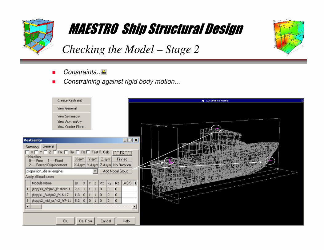
Checking the Model – Stage 2
� Constraints…
� Constraining against rigid body motion…

MAESTRO Ship Structural Design
General Steps – FEA Process
MAESTRO is a finite element modeling and post-processing application that allows you
to perform full-ship structural analyses both quickly and confidently.
� The FEA process can be broken down into the following stages:• Stage 1 – Geometry/Finite Element Modeling
• Stage 2 – Checking the model
• Stage 3 – Loading the model
• Stage 4 – Analyzing the model
• Stage 5 – Post-processing
• Stage 6 – Documenting Results
� We will now look at how we can use MAESTRO to accomplish each step in the FEA
process.
MAESTRO Ship Structural Design
Loading the Model – Stage 3
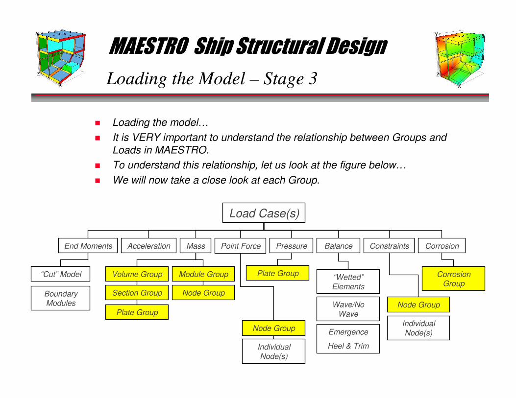
� Loading the model…
� It is VERY important to understand the relationship between Groups and
Loads in MAESTRO.
� To understand this relationship, let us look at the figure below…
� We will now take a close look at each Group.
Load Case(s)
End Moments Acceleration Mass Point Force Pressure Balance Constraints Corrosion
“Cut” Model
Boundary Modules
Volume Group Module Group
Section Group Node Group
Plate Group
Node Group
Individual
Node(s)
Plate Group
Node Group
Individual
Node(s)
Corrosion Group
“Wetted”
Elements
Wave/No
Wave
Emergence
Heel & Trim
MAESTRO Ship Structural Design
Loading the Model – Stage 3
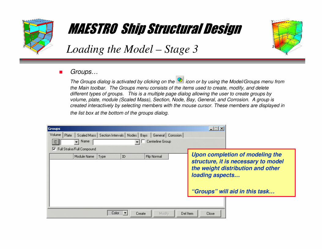
� Groups…
The Groups dialog is activated by clicking on the icon or by using the Model/Groups menu from
the Main toolbar. The Groups menu consists of the items used to create, modify, and delete
different types of groups. This is a multiple page dialog allowing the user to create groups by
volume, plate, module (Scaled Mass), Section, Node, Bay, General, and Corrosion. A group is
created interactively by selecting members with the mouse cursor. These members are displayed in
the list box at the bottom of the groups dialog.
Upon completion of modeling the structure, it is necessary to model the weight distribution and other loading aspects…
“Groups” will aid in this task…
MAESTRO Ship Structural Design
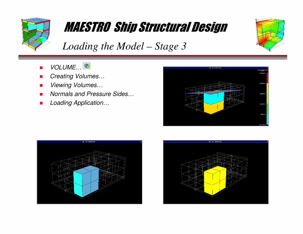
Loading the Model – Stage 3
� VOLUME…
� Creating Volumes…
� Viewing Volumes…
� Normals and Pressure Sides…
� Loading Application…
MAESTRO Ship Structural Design
Loading the Model – Stage 3
� PLATE…
The plate group provides a convenient way to apply a load to a collection
of plate elements, for example, Deck Loading.
� We will now digress for a moment to discuss:• Mirroring, translating and rotating modules
• Issues to be aware of and how to handle them
• Planning the FE model
� Mirroring Modules (via Parts menu and right-mouse-click)
� Translating and Rotating Modules (Parts Dialog)
� Overlapped Elements
� Element normals and saving a step when creating Volume groups
� Patterns in creating an FE model (think ahead)

MAESTRO Ship Structural Design
Loading the Model – Stage 3
� PLATE… (Back to Plate Groups)
The plate group provides a convenient way to apply a load to a collection
of plate elements, for example, Deck Loading.
� Creating Plate…
� Plate Mass…
� Plate Pressure…
� Loading Application…
� Open 270-WMEC_train.mdl …
MAESTRO Ship Structural Design
Loading the Model – Stage 3
� MODULE…
• This group is used to define a mass whose spatial distribution closely approximates the surrounding structure.
• The mass is distributed among the structural nodes in the same proportion as the structural mass, and can represent items such as furniture, paneling, auxiliary machinery, or any additional structural weight.
• This can also be used as a tool to match a known weight distribution.
� View Weight Distribution…
� Create Module Group…
� Loading Application (matching lightship)…
� View Weight Distribution…

MAESTRO Ship Structural Design
Loading the Model – Stage 3
� SECTION…
• A sections group is used to define a mass which is distributed among the sections of a module.
• The additional mass on the module can be either equal for all sections, or different for each section.
• Within each section, each endpoint-generated node carries the same mass.
� Create Section Group…
� Loading Application (matching lightship)…
� View Weight Distribution…
MAESTRO Ship Structural Design
Loading the Model – Stage 3
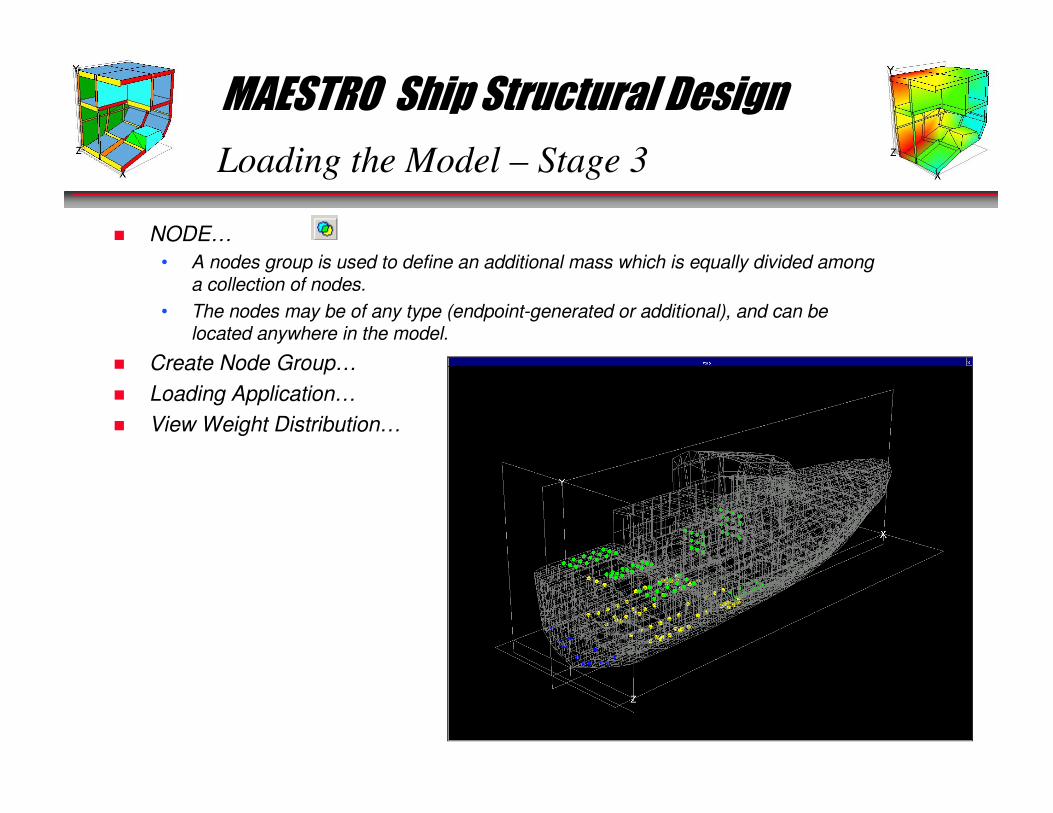
� NODE…
• A nodes group is used to define an additional mass which is equally divided among a collection of nodes.
• The nodes may be of any type (endpoint-generated or additional), and can be located anywhere in the model.
� Create Node Group…
� Loading Application…
� View Weight Distribution…

MAESTRO Ship Structural Design
Loading the Model – Stage 3
� GENERAL…
• The General groups dialog is a convenient way for the user to create a collection of elements for viewing "areas of interest."
• The General groups is also used create a General group which can then be refined for fine meshing.
� Create General Group…
� Run an analysis…
� View Results…
� Set General Group as Current…
� Results/View List Elements…
MAESTRO Ship Structural Design
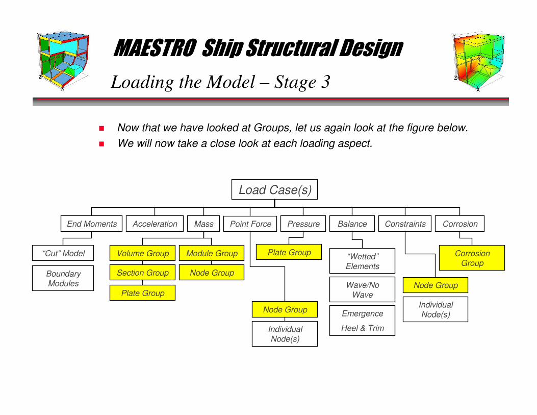
Loading the Model – Stage 3
� Now that we have looked at Groups, let us again look at the figure below.
� We will now take a close look at each loading aspect.
Load Case(s)
End Moments Acceleration Mass Point Force Pressure Balance Constraints Corrosion
“Cut” Model
Boundary Modules
Volume Group Module Group
Section Group Node Group
Plate Group
Node Group
Individual
Node(s)
Plate Group
Node Group
Individual
Node(s)
Corrosion Group
“Wetted”
Elements
Wave/No
Wave
Emergence
Heel & Trim

MAESTRO Ship Structural Design
Loading the Model – Stage 3
� Loads…
• The Loads dialog is activated by clicking on the icon or by using the Load/Create Load menu from the Main toolbar.
• A load case consists of all of the loads which act on the structure at the same time. Loads which do not act simultaneously should be placed in separate load cases (unless their interaction is negligible).
• Each load case produces a separate solution for the nodal displacements, and hence load effects, in the structure.
• In the evaluation portion of MAESTRO, for each possible limit state, the solutions for all load cases are examined to find the worst case (lowest adequacy parameter) for that limit state.
• A dynamic load case requires masses and accelerations.
MAESTRO Ship Structural Design
Loading the Model – Stage 3
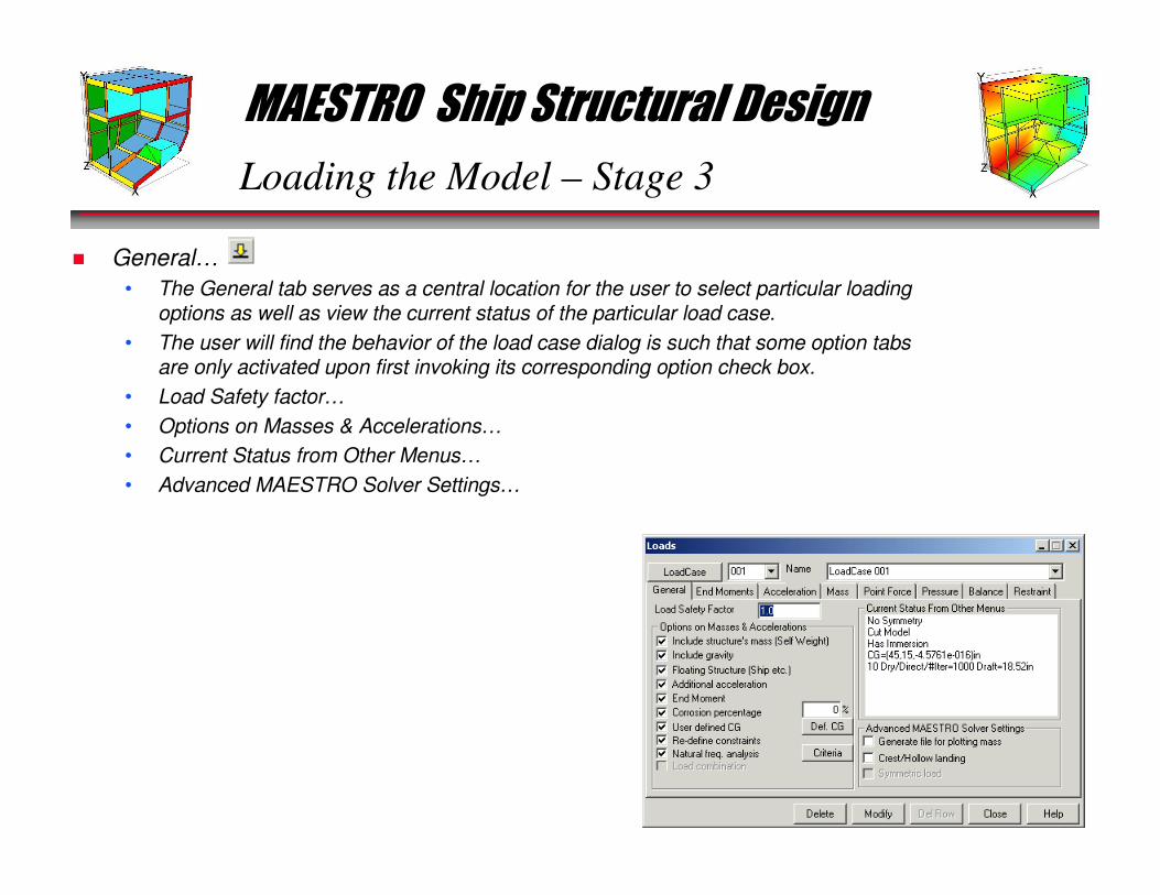
� General…
• The General tab serves as a central location for the user to select particular loading options as well as view the current status of the particular load case.
• The user will find the behavior of the load case dialog is such that some option tabs are only activated upon first invoking its corresponding option check box.
• Load Safety factor…
• Options on Masses & Accelerations…
• Current Status from Other Menus…
• Advanced MAESTRO Solver Settings…
MAESTRO Ship Structural Design
Loading the Model – Stage 3
� NOTE:
• In non-SI systems of units that specify densities in force units, the masses should be defined in terms of weight. Throughout this section the word "mass" should be taken to read "mass (or weight)" with the latter applying for non-SI systems. For non-SI systems the program internally converts from weight to a consistent mass unit (weight divided by gravity). Therefore in the program output (when applicable) the word "mass" should again be taken to read "mass (or weight)" with the latter applying for non-SI systems. Some exceptions occur if you specify a high level of program output (again, when applicable) because then the program will be printing the values that it is actually working with, which are the consistent mass values.
• In a half model all specified values of mass should be half values. At present, for a half model, all masses (except for Bay Set) are assumed to be symmetric and hence there is no need to define the corresponding mass in the un-modeled half. Even if a mass is used in an unsymmetrical load case, the program will assume that there is an equal mass in the un-modeled half. An exception to this is the definition of container (or other) masses in terms of bays and sets, for which it is possible to have different sets in the modeled and un-modeled halves.
MAESTRO Ship Structural Design
Loading the Model – Stage 3
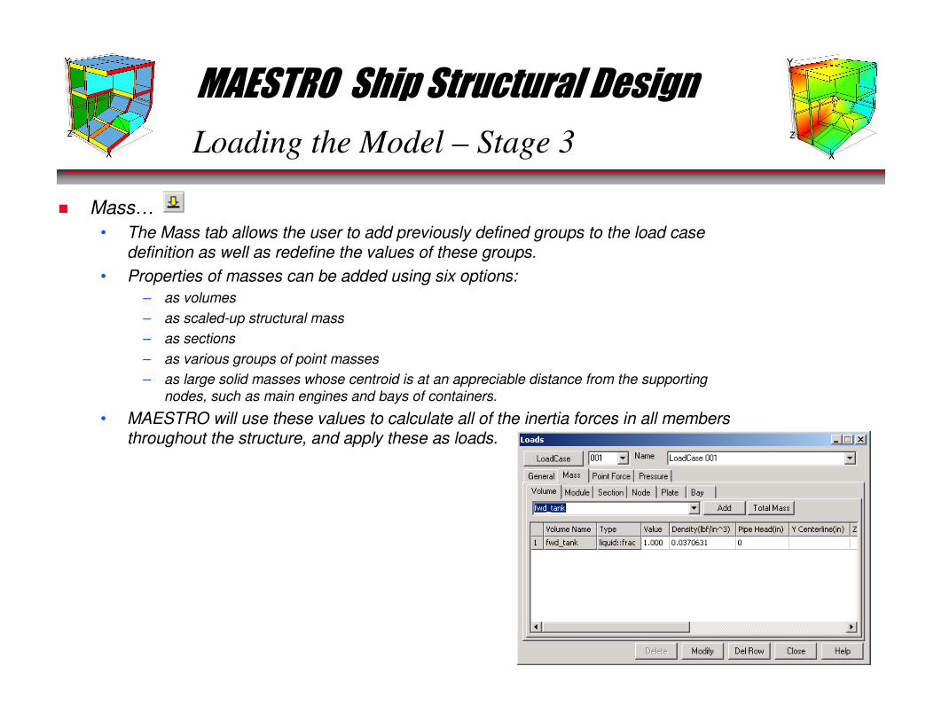
� Mass…
• The Mass tab allows the user to add previously defined groups to the load case definition as well as redefine the values of these groups.
• Properties of masses can be added using six options:
– as volumes
– as scaled-up structural mass
– as sections
– as various groups of point masses
– as large solid masses whose centroid is at an appreciable distance from the supporting
nodes, such as main engines and bays of containers.
• MAESTRO will use these values to calculate all of the inertia forces in all members throughout the structure, and apply these as loads.
MAESTRO Ship Structural Design
Loading the Model – Stage 3
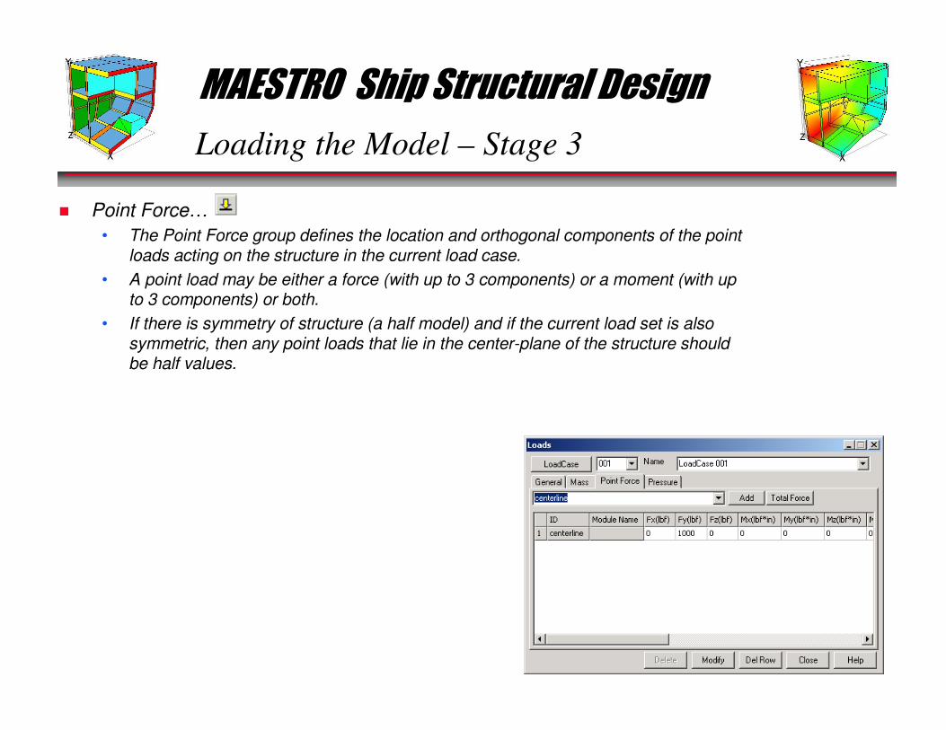
� Point Force…
• The Point Force group defines the location and orthogonal components of the point loads acting on the structure in the current load case.
• A point load may be either a force (with up to 3 components) or a moment (with up to 3 components) or both.
• If there is symmetry of structure (a half model) and if the current load set is also symmetric, then any point loads that lie in the center-plane of the structure should be half values.
MAESTRO Ship Structural Design
Loading the Model – Stage 3
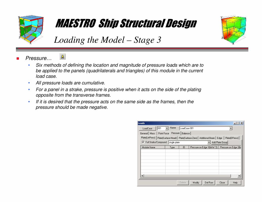
� Pressure…
• Six methods of defining the location and magnitude of pressure loads which are to be applied to the panels (quadrilaterals and triangles) of this module in the current load case.
• All pressure loads are cumulative.
• For a panel in a strake, pressure is positive when it acts on the side of the plating opposite from the transverse frames.
• If it is desired that the pressure acts on the same side as the frames, then the pressure should be made negative.
MAESTRO Ship Structural Design
Loading the Model – Stage 3
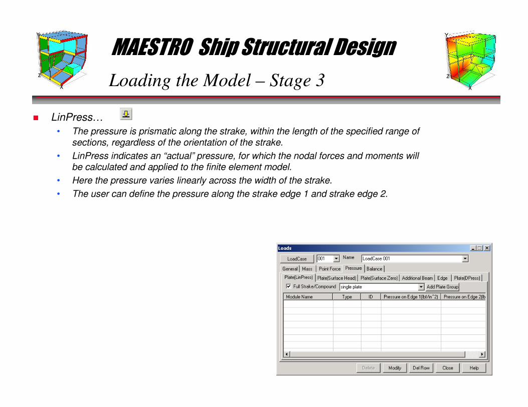
� LinPress…
• The pressure is prismatic along the strake, within the length of the specified range of sections, regardless of the orientation of the strake.
• LinPress indicates an “actual” pressure, for which the nodal forces and moments will be calculated and applied to the finite element model.
• Here the pressure varies linearly across the width of the strake.
• The user can define the pressure along the strake edge 1 and strake edge 2.

MAESTRO Ship Structural Design
Loading the Model – Stage 3
� Surface Head…• The surface option is intended for hydrostatic pressure, for which the value is proportional to the
depth below the free surface of a fluid.
• In the Surface option the pressure is always an actual pressure, not a design pressure.
• For strake panels the pressure varies linearly across the strake width, in proportion to the local depth below the zero pressure surface, and in the lengthwise direction it is constant over each
panel and is calculated separately for each panel, based on the depth of that panel below the zero
pressure surface.
• For additional (non-strake) panels and for triangles, the pressure is calculated at each corner of
the element and then multiplied by either one fourth or one third of the element area.
MAESTRO Ship Structural Design
Loading the Model – Stage 3
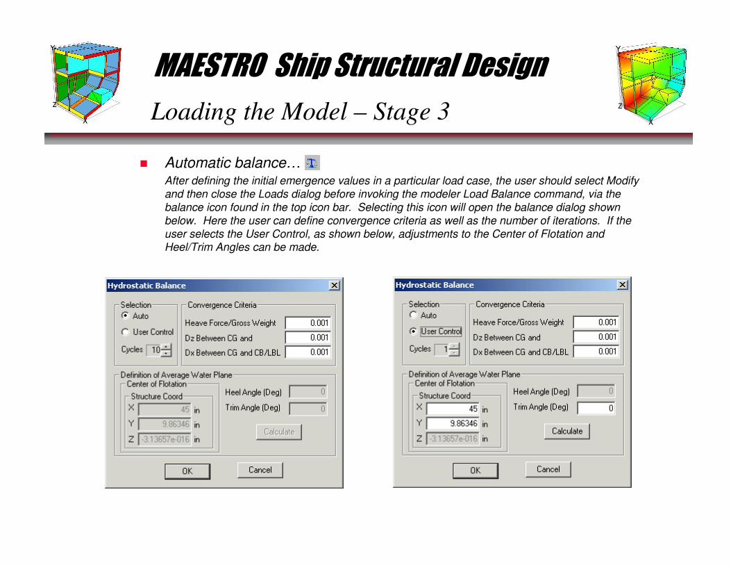
� Automatic balance…After defining the initial emergence values in a particular load case, the user should select Modify
and then close the Loads dialog before invoking the modeler Load Balance command, via the
balance icon found in the top icon bar. Selecting this icon will open the balance dialog shown
below. Here the user can define convergence criteria as well as the number of iterations. If the
user selects the User Control, as shown below, adjustments to the Center of Flotation and Heel/Trim Angles can be made.

MAESTRO Ship Structural Design
General Steps – FEA Process
MAESTRO is a finite element modeling and post-processing application that allows you
to perform full-ship structural analyses both quickly and confidently.
� The FEA process can be broken down into the following stages:• Stage 1 – Geometry/Finite Element Modeling
• Stage 2 – Checking the model
• Stage 3 – Loading the model
• Stage 4 – Analyzing the model
• Stage 5 – Post-processing
• Stage 6 – Documenting Results
� We will now look at how we can use MAESTRO to accomplish each step in the FEA
process.
MAESTRO Ship Structural Design
Analyzing the Model – Stage 4
� Running a MAESTRO analysis (Com-solver v. Scalable solver)
• The traditional MAESTRO solver (referred to as the MAESTRO Scalable solver because the arrays are automatically scaled to the required size) requires the creation of a data file, called jobname.DAT.
• Traditionally, modeler's sole purpose was to create a MAESTRO data input file that was submitted to the solver at the time of analysis.
• With the introduction of the MAESTRO Version 8.5, came MAESTRO COM Solver, the corner stone of the next generation of MAESTRO solvers.
• With the inception of the COM Solver, there is no need to create a data file, assuming the user intends to use the COM Solver to analyze the structural system.
• MAESTRO COM Solver DOES NOT perform the calculation of limit states and the subsequent evaluation of these limit states. This area ranks very high on the development priority list but currently are not supported by COM Solver.
• Please see the Appendix B: Data Preparation Manual for a complete description of the *.DAT file.
MAESTRO Ship Structural Design
Analyzing the Model – Stage 4
� Running a MAESTRO analysis…
Once the loads appear to be correct, you are ready to perform a finite element analysis of the current model. In the Job
Info option under the File menu, select the extent and levels for the calculation of stresses and for the evaluation of
structural adequacy (for Scalable Solver only). Then run MAESTRO, which will now calculate the deformations, the
stresses and the adequacy parameters (Scalable Solver) in some or all of the members. Then use Modeler to plot the
deformed shape and to obtain color-added displays of the stresses and adequacy parameters. Check the results carefully to see if there are any inconsistencies and if so, whether these are due to errors in the model or in the loads.
MAESTRO Ship Structural Design
General Steps – FEA Process
MAESTRO is a finite element modeling and post-processing application that allows you
to perform full-ship structural analyses both quickly and confidently.
� The FEA process can be broken down into the following stages:• Stage 1 – Geometry/Finite Element Modeling
• Stage 2 – Checking the model
• Stage 3 – Loading the model
• Stage 4 – Analyzing the model
• Stage 5 – Post-processing
• Stage 6 – Documenting Results
� We will now look at how we can use MAESTRO to accomplish each step in the FEA
process.
MAESTRO Ship Structural Design
� Black/white…
� Animation…
� Load selection…
� View Options…
� Gray On/Off…
� Dynamic query…
� Contour plot…
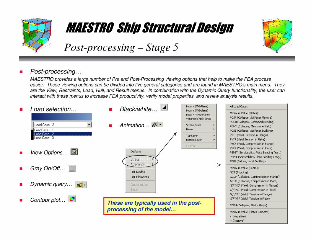
Post-processing – Stage 5
� Post-processing…MAESTRO provides a large number of Pre and Post-Processing viewing options that help to make the FEA process
easier. These viewing options can be divided into five general categories and are found in MAESTRO's main menu. They
are the View, Restraints, Load, Hull, and Result menus. In combination with the Dynamic Query functionality, the user can
interact with these menus to increase FEA productivity, verify model properties, and review analysis results.
These are typically used in the post-processing of the model…

MAESTRO Ship Structural Design
Post-processing – Stage 5
� Load selection…
� Dynamic query…
� Local X…
� Local Y…
� Local XY…
� von Misses…
MAESTRO Ship Structural Design
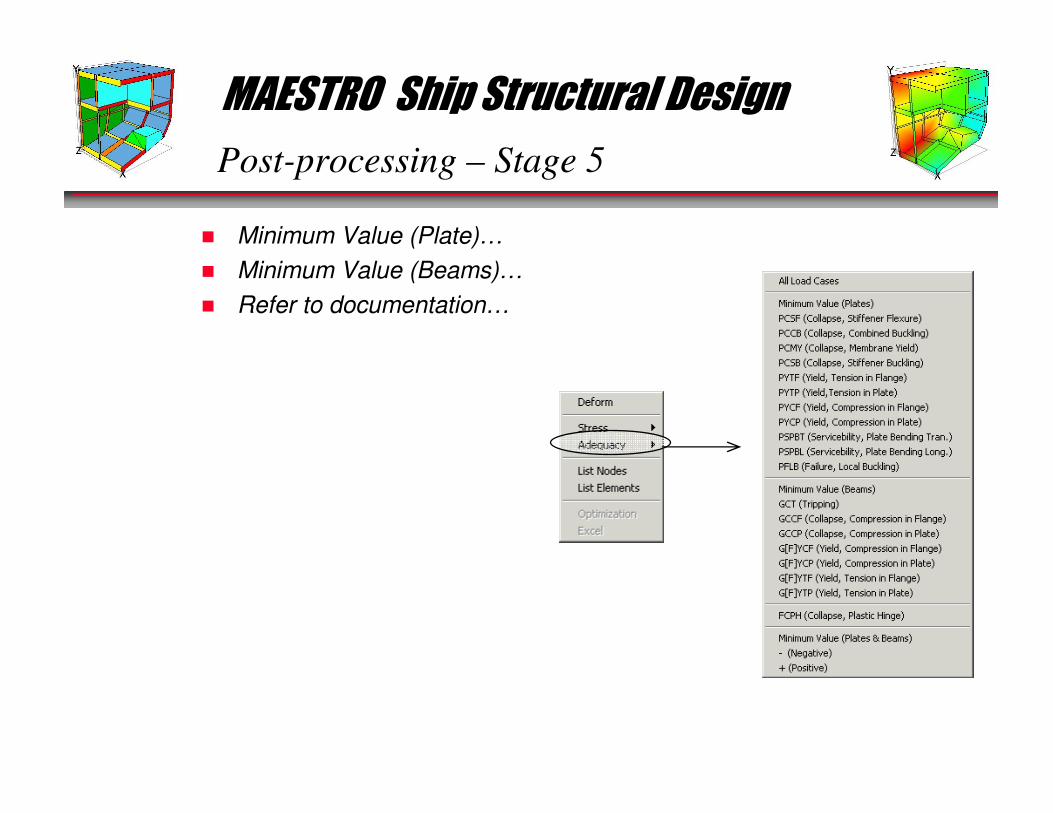
Post-processing – Stage 5
� Minimum Value (Plate)…
� Minimum Value (Beams)…
� Refer to documentation…
MAESTRO Ship Structural Design
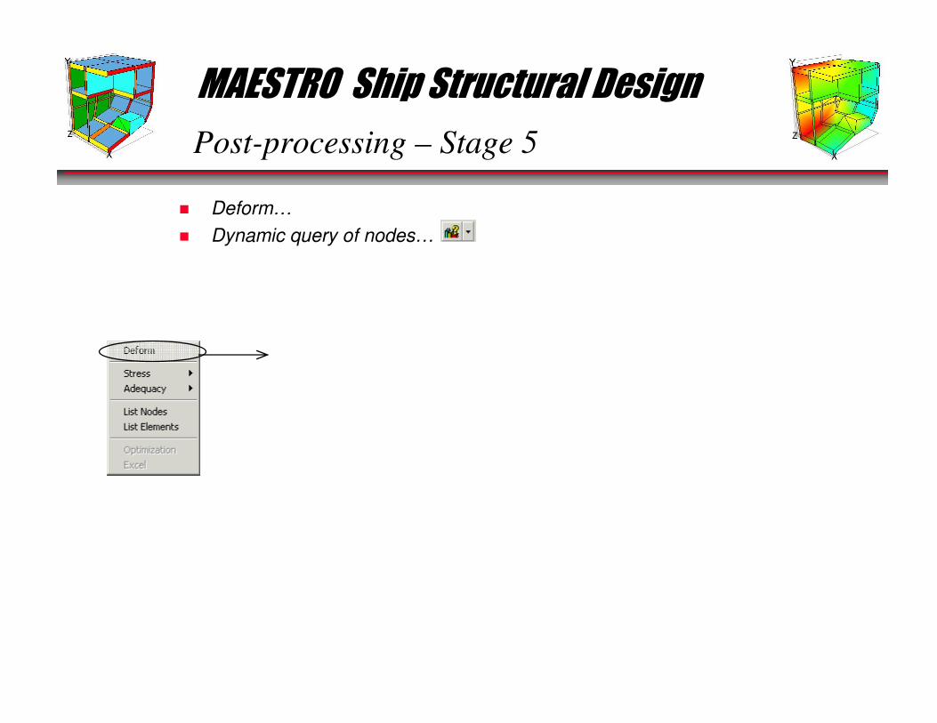
Post-processing – Stage 5
� Deform…
� Dynamic query of nodes…

MAESTRO Ship Structural Design
General Steps – FEA Process
MAESTRO is a finite element modeling and post-processing application that allows you
to perform full-ship structural analyses both quickly and confidently.
� The FEA process can be broken down into the following stages:• Stage 1 – Geometry/Finite Element Modeling
• Stage 2 – Checking the model
• Stage 3 – Loading the model
• Stage 4 – Analyzing the model
• Stage 5 – Post-processing
• Stage 6 – Documenting Results
� We will now look at how we can use MAESTRO to accomplish each step in the FEA
process.
MAESTRO Ship Structural Design
Documenting Results – Stage 6
� Screen Capture…
� Dynamic Query echo…
• Advanced Modeling Techniques
• Advanced Topics
– Fine Meshing
– Eigenvalue Analyses
– Importing/Exporting FEMAP
– Importing FastShip (idf)
• Review and questions
MAESTRO Ship Structural Design
Advanced Modeling Techniques
� Merging two models…
� Importing DXF files…
� Importing/Exporting FEMAP…
� Importing IDF files…
� Eigenvalue Analyses…
� Fine Meshing…• R-Splines
• Exporting to FEMAP
MAESTRO Ship Structural Design
Review and Questions
� Review…
� Questions…

MAESTRO Ship Structural Design
MAESTRO Documentation/Tech Support
� Documentation…• MAESTRO help manual can be accessed via the Help/Contents menu item.
• Hughes. O. F.,Ship Structural Design – A Rationally-Based, Computer-Aided Optimization Approach, SNAME
� Technical Support• Email: [email protected]
• Fax: +1 (410) 643-5370
• Telephone: +1 (410) 604-8000